

Page 1
JVC
AUDIO/VIDEO CONTROL RECEIVER
RX-8030VBK
RX-7030VB K/RX-7032VSL
_BW _urw Ir_lvBlk
/fl/_////
DB_
DIGITAL. EX
_"=]1=Ko] II[e][_l E ! III
_-_,_,_ (For RX-803OVBK)
rr
__'__
(For RX-8030VBK)
a a
o_o
NSTRUCTIONS
For Customer Use:
Enter below the Model No. and Seria+
No. which are located either on the rear,
bottom or side of the cabinet. Retain this
information for future reference.
Model No.
Serial No.
LVT1007-001A[J]
Page 2
Warnings, Cautions and Others/
Mises en garde, precautions et indications diverses
For U.S.A
This equipment has been tested and found to comply with the limits
for a Ctass B digitat device, pursuant to part 15 of the FCC Rules.
CAUTION: TO REDUCE THE RISK OF ELECTRIC SHOCK.
REFER SERVICING TO QUALIFIED SERVICE PERSONNEL.
DO NOT REMOVE COVER (OR BACK)
NO USER SERVICEABLE PARTS INSIDE.
The lightning flash with arrowhead symbol,
within an equilateral triangle is intended to
alert the user to the presence of uninsulated
"dangerous voltage" within the product's
enclosure that may be of sufficient
magnitude to constitute a risk of electric
shock to persons.
The exclamation point within an equilateral
triangle is intended to alert the user to the
presence of important operating and
maintenance (servicing) instructions in the
literature accompanying the appliance.
These limits are designed to provide reasonable protection against
harmful interference in a residential installation.
This equipment generates, uses and can radiate radio frequency
energy and, if not installed and used in accordance with the
instructions, may cause harmfut interference to radio
communications. However, there is no guarantee that interference
will not occur in a particular installation. If this equipment does cause
harmful interference to radio or television reception, which can be
determined by turning the equipment off and on, the user is
encouraged to try to correct the interference by one or more of the
following measures:
Reorient or relocate the receiving antenna.
Increase the separation between the equipment and receiver.
Connect the equipment into an outlet on a circuit different from that
to which the receiver is connected.
Consult the dealer or an experienced radio/TV technician for help.
Changes or modifications not expressly approved by the
manufacturer for compliance coutd void the user s authority to
opratethe equipment.
WARNING: TO REDUCE THE RISK OF FIRE
OR ELECTRIC SHOCK, DO NOT EXPOSE
THIS APPLIANCE TO RAIN OR MOISTURE.
CAUTION
To reduce the risk of electrical shocks, fire, etc.:
1. Do not remove screws, covers or cabinet.
2. Do not expose this appliance to rain or moisture.
ATTENTION
Afin d'_viter tout risque d'_lectrocution, d'incendie, etc.:
1. Ne pas enlever les vis ni _es panneaux et ne pas ouvrir le
coffret de I'appareiL
2. Ne pas exposer I'appareil & _apluie ni & I'humidit&
Caution i O/I STANDBY/ON button!
Disconnect the mains plug to shut the power off completely. The
OIl STANDBY/ON button in any position does not disconnect
the mains line. The power can be remote controlled.
Attention -- Commutateur Oil STANDBY/ON!
D_connecter la fiche de secteur pour cocper compl_tement le
courant. Le commutateur Oil STANDBY/ON ne coupe jamais
compt_tement laligne de secteur, quelle que soit sa position. Le
courant pout 6tre t_i_command&
I
Note to CATV system installer:
This reminder is provided to call the CATV system instatler's
attention to Section 820-40 of the NEC which provides guidelines for
proper grounding and, in particular, specifies that the cabte ground
shall be connected to the grounding system of the building, as close
to the point of cabte entry as practical.
For Canada/pour Le Canada
CAUTION: TO PREVENT ELECTRIC SHOCK, MATCH WIDE
BLADE OF PLUG TO WIDE SLOT, FULLY INSERT
ATTENTION: POUR EVITER LES CHOCS ELECTRIQUES,
INTRODUIRE LA LAME LA PLUS LARGE DE LA FICHE DANS LA
BORNE CORRESPONDANTE DE LA PRISE ET POUSSER
JUSQUAU FOND
THIS DIGITAL APPARATUS DOES NOT EXCEED THE CLASS B
LIMITS FOR RADIO NOISE EMISSIONS FROM DIGITAL APPA-
RATUS AS SET OUT IN THE INTERFERENCE-CAUSING
EQUIPMENT STANDARD ENTITLED "DIGITAL APPARATUS,"
ICES-gO3 OF THE DEPARTMENT OF COMMUNICATIONS.
CET APPAREIL NUMERIQUE RESPECTE LES LIMITES DE
BRUITS RADIOELECTRIQUES APPLICABLES AUX APPAREILS
NUMERIQUES DE CLASSE B PRESCRITES DANS LA NORME
SUR LE MATERIEL BROUILLEUR; "APPAREILS NUMERIQUES",
NMB-OO3 EDICTEE PAR LE MINISTRE DES COMMUNICATIONS.
G-1
Page 3
Table of Contents
Introduction ................................................ 2
Features ...................................................................................... 2
Precautions ................................................................................. 2
Parts Identification ...................................... 3
Remote Control .......................................................................... 3
Fmnt Panel ................................................................................. 4
Rear Panel .................................................................................. 6
Getting Started ........................................... 8
Before Installation ...................................................................... 8
Checking the Supplied Accessories ........................................... 8
Pulting Batteries in the Remote Control .................................... 8
Connecting the FM and AM Antennas ....................................... 8
Connecting the Speakers ............................................................ 9
Connecting Audio/Video Components ..................................... 11
• Analog Connections ............................................................. 11
• Digital Connections .............................................................. 16
Connecting the Power Cord ..................................................... 16
Basic Operations ....................................... 17
Daily Operational Procedure .................................................... 17
Turning On the Power .............................................................. 17
Selecting the Source Io Play ..................................................... 17
Adjusting the Volume ............................................................... 18
Selecting the Front Speakers .................................................... 19
Activating and Adjusting the Subwoofer Sound ...................... 19
Selecting the Analog or Digital Input Mode ............................ 19
Setting the Dynamic Range ...................................................... 20
Attenuating the Input Signal .................................................... 20
Turning Analog Direct On and Off .......................................... 21
Making Sounds Natural ............................................................ 21
Changing the Source Name ...................................................... 21
Reinforcing the Bass ................................................................ 22
Muting the Sound ..................................................................... 22
Changing the Display Brightness ............................................. 22
Using the Sleep Timer .............................................................. 22
Basic Settings ........................................... 25
Setting the Speakers Configuration .......................................... 25
Basic Setting Items ................................................................... 26
Basic Procedure ........................................................................ 27
Setting the Speakers ........................................................... 27
Setting the Speaker Distance ............................................. 28
Setting the Bass Sounds ..................................................... 28
Selecting main or sub channel_DUAL MONO ............... 29
Seuing the Digital Input Terminals .................................... 29
Setting the Component Video Input ................................... 30
Memorizing the Volume Level for Each Source ................ 30
Adjusting Sound ........................................ 31
Basic Setting Items ................................................................... 31
Basic Procedure ........................................................................ 31
Adjusting the Equalization Patterns ................................... 32
Adjusting the Speaker Oulput Levels ................................ 32
Adjusting the Sound Parameters for the
Surround and DSP modes ............................................ 33
Using the Surround Modes .......................... 34
Reproducing Theater Ambience ................................................ 34
Introducing 1he Sun'ound Modes ............................................. 34
Sun'ound Modes Applicable to the Various Software .............. 36
Activating the Surround Modes ............................................... 37
• Activating the EX/ES setting ................................................ 37
• Activating the Surroung modes ............................................ 37
Using the DSP Modes ................................ 38
Reproducing the Sound Field ................................................... 38
Introducing 1he DSP Modes ..................................................... 38
Activating the DSP Modes ....................................................... 39
Using the DVD MULTI Playback Mode .......... 40
Activating the DVD MUUI'I Playback Mode .......................... 40
COMPU LINK Remote Control System ......... 41
Receiving Radio Broadcasts ........................ 23
Tuning in to Stations Manually ................................................ 23
Using Preset Tuning ................................................................. 23
Selecting the FM Reception Mode ........................................... 24
AV COMPU LINK Remote Control System .... 42
Operating JVC's Audio/Video Components ... 44
Operaling Audio Components .................................................. 44
Operating Video Components .................................................. 46
Operating Other Manufacturers' Video
Equipment ............................................ 47
Troubleshooting ......................................... 50
Specifications ............................................ 51
1
Page 4
I Introduction
We would like to thank you far purchasing one of our JVC products,
Before operating this unit, read this manual carefully and thoroughly to obtain the best possible performance
from your unit, and retain this manual for future reference,
CC (Compensative Compression) converter
--ONLY for RX-8030VBK
CC Converter eliminates jitler anti ripples, achieving a drastic
reduction in digital distortion by processing the digital music data
in 24 bit_quantization and by expanding the sampling frequency
to 128 kHz (for fs 32 kHz signals)/176.4 kHz (for fs 44.1 kHz
signals)/192 kHz (for fs 48 kHz signals). By using the CC
Converler, you can obtain a natural sound field from any source.
(See page 21 fur details.)
K2 technology--ONLY for RX-8030VBK
K2 technology has been designed to enable natural audio
reproduction, achieving a drastic reduction in digital distortion
and creating original sound ambience with high precision.
Compatible with various audio formats including
DTS 96/24
RX-8030VBK and RX-7030VBK/RX-7032VSL allow you to
enjoy a newly introduced audio formal such as Dolby Digital EX,
Dolby Pro Logic II, DTS-ES, DTS Neo:6, and DTS 96/24.
• This unit is also compatible with Dual Mono signals recorded in
Dolby Digital and DTS discs.
DAP (Digital Acoustic Processor)
Sound field simulation technology allows precise ambience
recrealion of existing theatens and halls. Thanks to the high-
performance DSP (Digital Signal Processor) and high-capacity
memory, you can enjoy multi-channel surround sound by playing
2-channel or multi-channel software according to the speaker
setting.
Power sources
• When unplugging the receiver from the wall outlet, always pull
the plug, not the AC power cord.
• Do not handle the AC power cord wilh wet hands.
• If you are no1 going to operate the receiver for an exlended period
of time, unplug the AC power coM from the wall outlet.
Ventilation
High power amplifiers built in this receiver will generate heat inside
the cabinet. For safety, observe the following carefully.
• Make sure there is good ventilation around the receiver. Poor
ventilation could overheat and damage the receiver.
• Do not block the ventilation openings or holes. (If the ventilation
openings or holes are blocked by a newspaper or cloth, elc., 1he
heat may not be able to get out.)
Others
• Should any metallic object or liquid fall onto the unit, unplug the
unit and consult your dealer before operating any further.
• Do not expose this apparalus to rain, moisture, dripping or
splashing and that no objects filled with liquids, such as vases
shall be placed on the apparalus.
• Do not disassemble 1he unit since there are no user serviceable
parts inside.
If anything goes wrong, unplug the AC power cord and consult your
JVC dealer.
Multi_channel headphone virtual surround
scund--3D HEADPHONE Mode
The built-in headphone virtual surround system is compatible with
Multi-channel software like Dolby Digital, DTS Surround, elc.
Thanks to the new signal processing algorithms used by the high-
performance DSR you can enjoy a natural surround sound through
the headphones.
COMPU LINK/AV COMPU LINK remote control
systems
These COMPU LINK remote control systems allow you to
operate other JVC's audio/video components from this receiver.
2
Page 5
Parts Identification
JVC
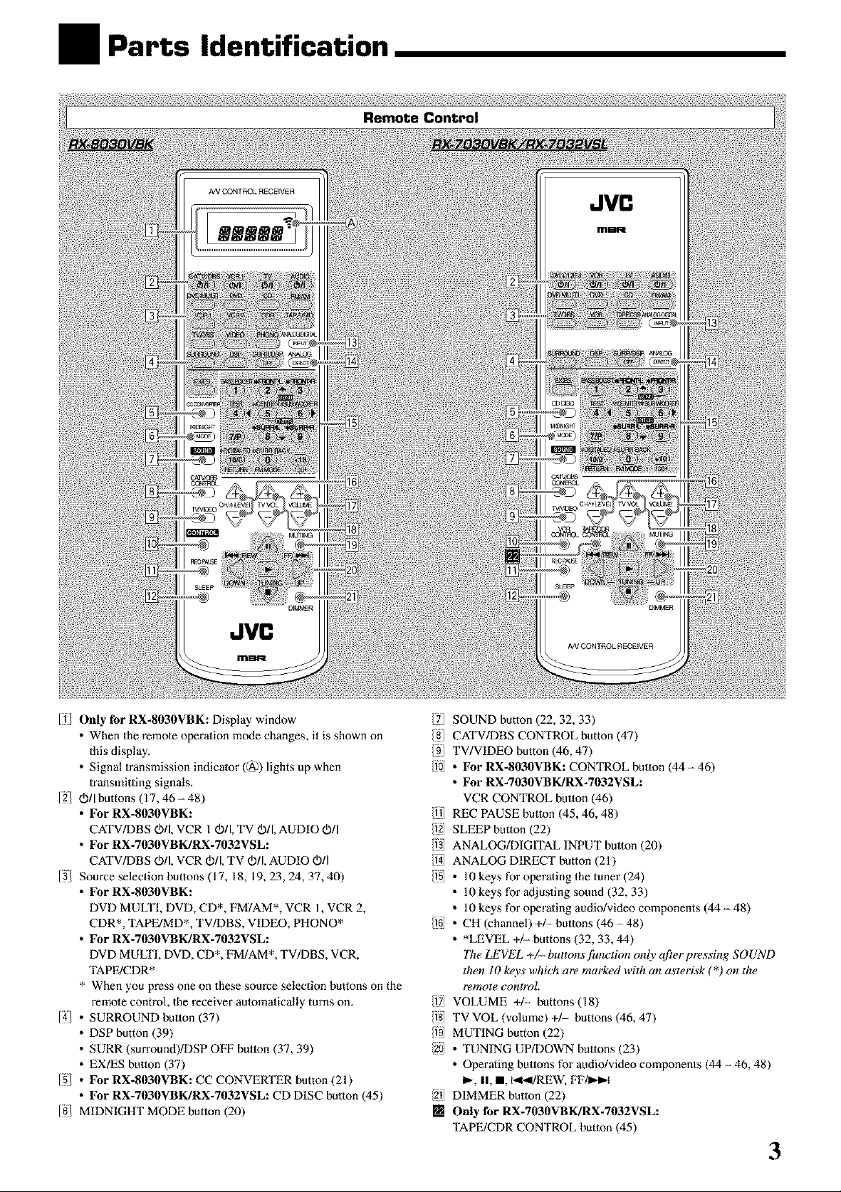
Ifl Only for RX-8030VBK: Display window
• When the rcmole operation mode changes, it is shown on
this display.
• Signal transmission indicator (@) lights up when
transmitting signals.
12/ Oil buttons (17, 46 - 48)
• For RX-8030VBK:
CATV/DBS O/I, VCR 1Oil, TV O/I, AUDIO O[I
• For RX-7030VBK/RX-7032VSL:
CA_/DB S O/I, VCR Oil, TV Oil, AUDIO Oil
13/ Source selection buttons (17, 18, 19, 23, 24, 37, 40)
• For RX-8030VBK:
DVD MULTI, DVD, CD*, FM/AM*, VCR 1, VCR 2,
CDR*, TAPE/MD*, TV/DBS, VIDEO, PHONO*
• For RX-7030VBK/RX-7032VSL:
DVD MULTI, DVD, CD*, FM/AM*, TV/DBS, VCR,
TAPE/CDR*
* When you press one on these source selection buttons on the
remote control, 1he receiver au_omalically turns on.
14_ • SURROUND button (37)
• DSP button (39)
• SURR (surround)/DSP OFF button (37, 39)
• EX/ES button (37)
15/ • For RX-8030VBK: CC CONVERTER button (21)
• For RX-7030VBK/RX-7032VSL: CD DISC button (45)
IN/MIDNIGHT MODE button (20)
/71 SOUND button (22, 32, 33)
/g] CATV/DBS CONTROL button (47)
/91 TV/VIDEO button (46, 47)
/10 ° For Rx-g030VBK: CONTROL button (44 - 46)
• For RX-7030VBK/RX-7032VSL:
VCR CONTROL button (46)
/111 REC PAUSE button (45, 46, 48)
/f2l SLEEP button (22)
/1)] ANALOG/DIGITAL INPUT button (20)
/l_(I ANALOG DIRECT button (21)
/151 ° 10 keys for operating the tuner (24)
• 10 keys for adjusting sound (32, 33)
• 10 keys for operating audio/video components (44 - 48)
If61 ° CH (channel) +1- buttons (46 - 48)
• *LEVEL +/- buttons (32, 33, 44)
77w LEVEL +/- buttons jhnction only after pressing SOUND
then I0 k_vs which are marked with an asterisk (*) on the
remote control.
/fTI VOLUME +/- buttons(18)
/fS] TVVOL (volume) +/- buttons (46, 47)
[i9 MUTING button (22)
/201 • TUNING UP/DOWN buttons (23)
• Operating buttons for audio/video components (44 - 46, 48)
_, II, l, 141_I/REW, FF/I_,-I
/211 DIMMER button (22)
[] Only for RX-7030VBK/RX-7032VSL:
TAPE/CDR CONTROL button (45)
3
Page 6
RX-8030VBK
D D D D
RX-7030VBK/RX-7032VSL
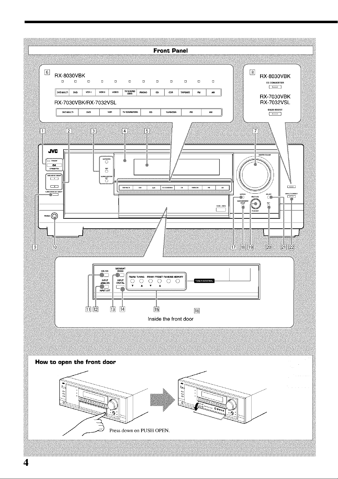
Front Panel
How to open the front door
4
Inside the front door
Press down on PUSH OPEN.
Page 7
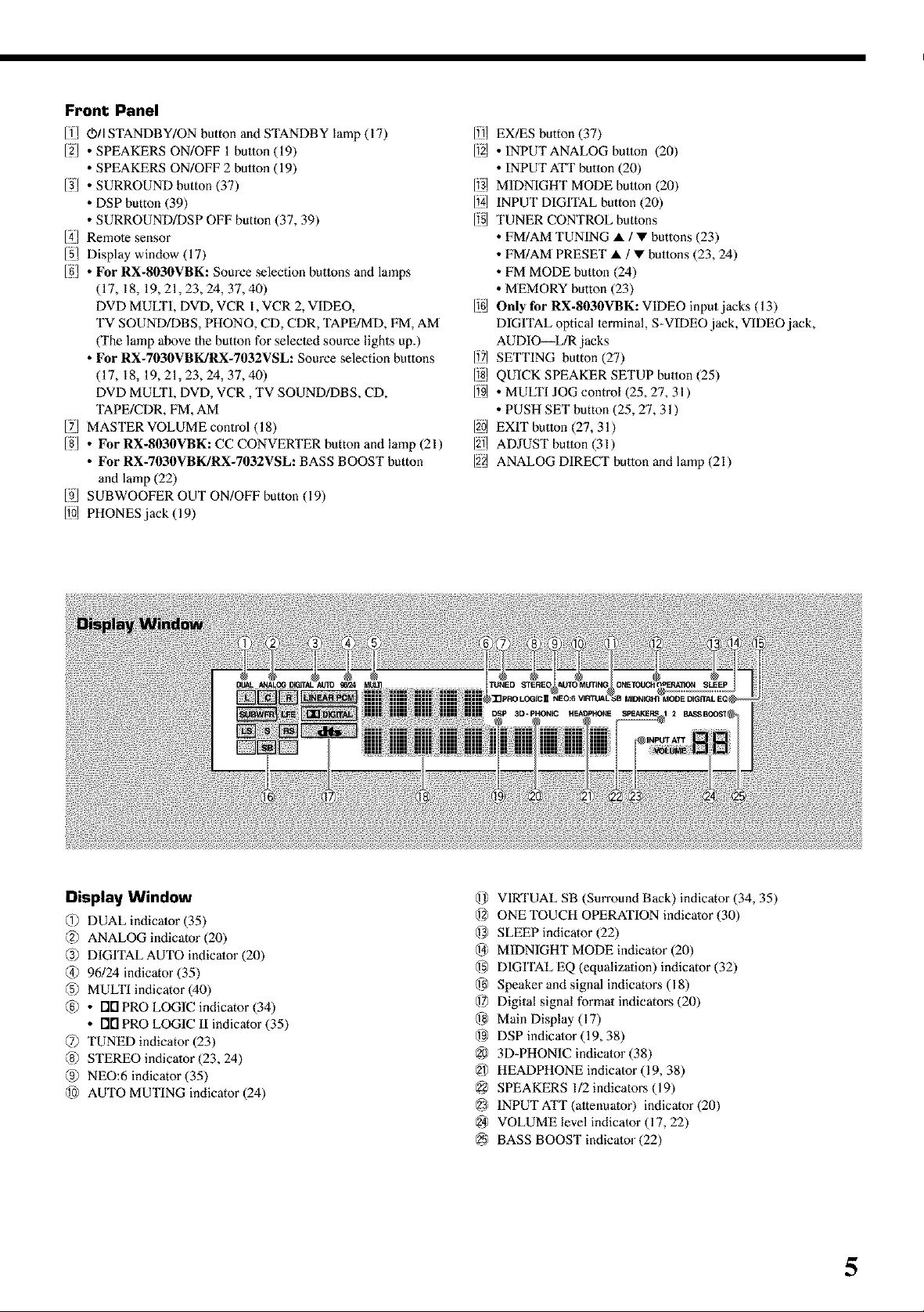
Front Panel
[f_ 0)/I STANDBY/ON button and STANDBY lamp (17)
[2/ • SPEAKERS ON/OFF 1 button (19)
• SPEAKERS ON/OFF 2 button (19)
13/ • SURROUND button (37)
• DSP button (39)
• SURROUND/DSP OFF button (37, 39)
[41 Remole sensor
151 Display window (17)
[g/ • For RX-8030VBK: Source selection buttons and lamps
(17, 18, 19,21,23,24,37,40)
DVD MULTI, DVD, VCR 1, VCR 2, VIDEO,
TV SOUND/DBS, PHONO, CD, CDR, TAPE/MD, FM, AM
(The lamp above the button for selecled source lights up.)
• For RX-7030VBK/RX-7032VSL: Source selection buttons
(17, 18, 19,21,23,24,37,40)
DVD MULTI, DVD, VCR, TV SOUND/DBS, CD,
TAPE/CDR, FM, AM
17J MASTER VOLUME control (18)
18/ • For RX-8030VBK: CC CONVERTER button and lamp (21)
• For RX-7030VBK/RX-7032VSL: BASS BOOST button
and lamp (22)
[ffJ SUBWOOFER OUT ON/OFF button (19)
[10/ PHONES jack (19)
lill EX/ES button (37)
112/ • INPUT ANALOG button (20)
• INPUT ATT button (20)
1131MIDNIGHT MODE button (20)
1121_INPUT DIGITAL button (20)
115/ TUNER CONTROL buttons
• FM/AM TUNING • / • buttons (23)
• FM/AM PRESET • / • buttons (23, 24)
• FM MODE button (24)
• MEMORY button (23)
I16LOnly for RX-8030VBK: VIDEO input jacks (13)
DIGITAL optical lermina[, S-VIDEO jack, VIDEO jack,
AUDIO_L/R jacks
lit] SETTING button (27)
II§l QUICK SPEAKER SETUP button (25)
1_9/ • MULTI JOG control (25, 27, 31 )
• PUSH SET button (25, 27, 31)
120_EXIT button (27, 31)
12i_ ADJUST button (31)
122/ ANALOG DIRECT button and lamp (21)
Display Window
@ DUAL indicator (35)
@ ANALOG indicator (20)
@ DIGITAL AUTO indicator (20)
@ 96/24 indicator (35)
(5) MULTI indicator (40)
@ • FIN PRO LOGIC indicator (34)
• i"IFIPRO LOGIC ll indicator (35)
@ TUNED indicator (23)
@ STEREO indicator (23, 24)
@ NEO:6 indicator (35)
@ AUTO MUTING indicator (24)
@ VIRTUAL SB (Surround Back) indicator (34, 35)
@ ONE TOUCH OPERATION indicator (30)
@ SLEEP indicator (22)
@ MIDNIGHT MODE indicator (20)
@ DIGITAL EQ (equalizalion) indicator (32)
@ Speaker and signal indicatol_s (18)
@ Digital signal formal indicators (20)
@ Main Display (17)
@ DSP indicator (19, 38)
@ 3D-PHONIC indicator (38)
@ HEADPHONE indicator (19, 38)
@ SPEAKERS 1/2 indicators (19)
@ INPUTATT(altenuator) indicalor(20)
@ VOLUME level indicator (17, 22)
@ BASS BOOST indicator (22)
5
Page 8
6
Page 9
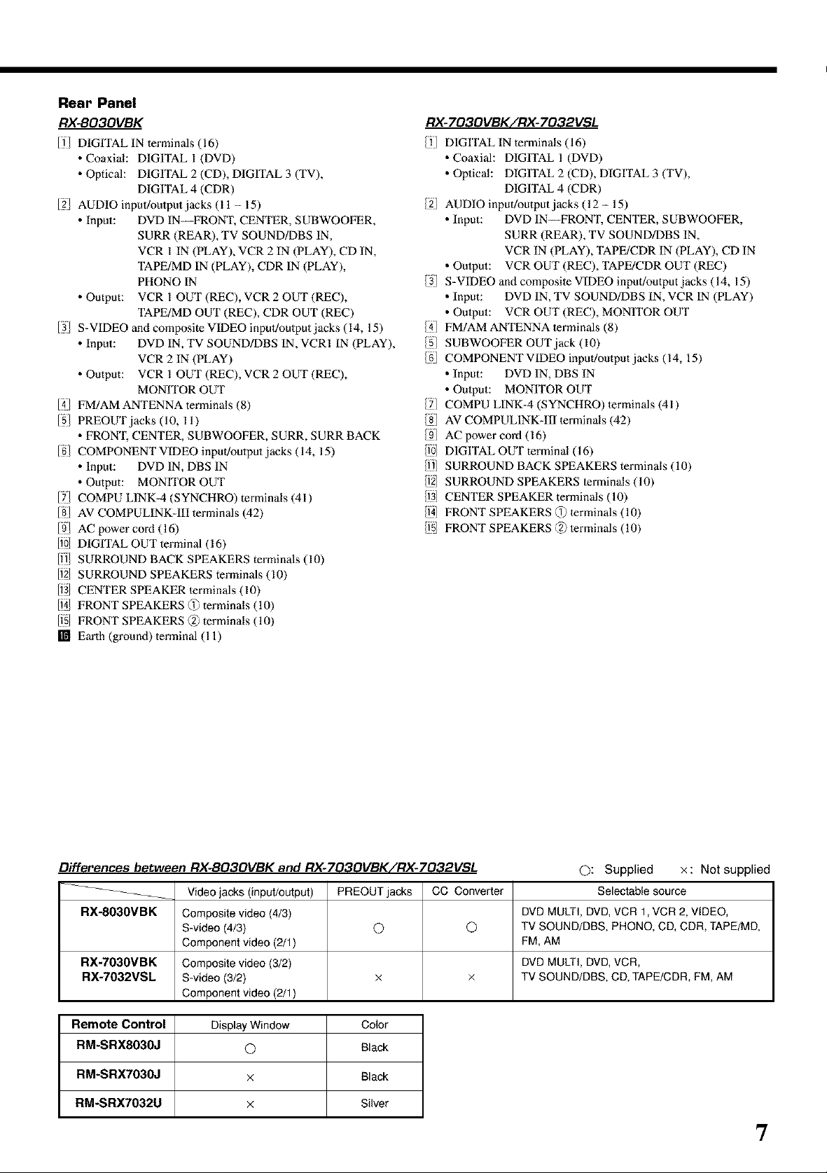
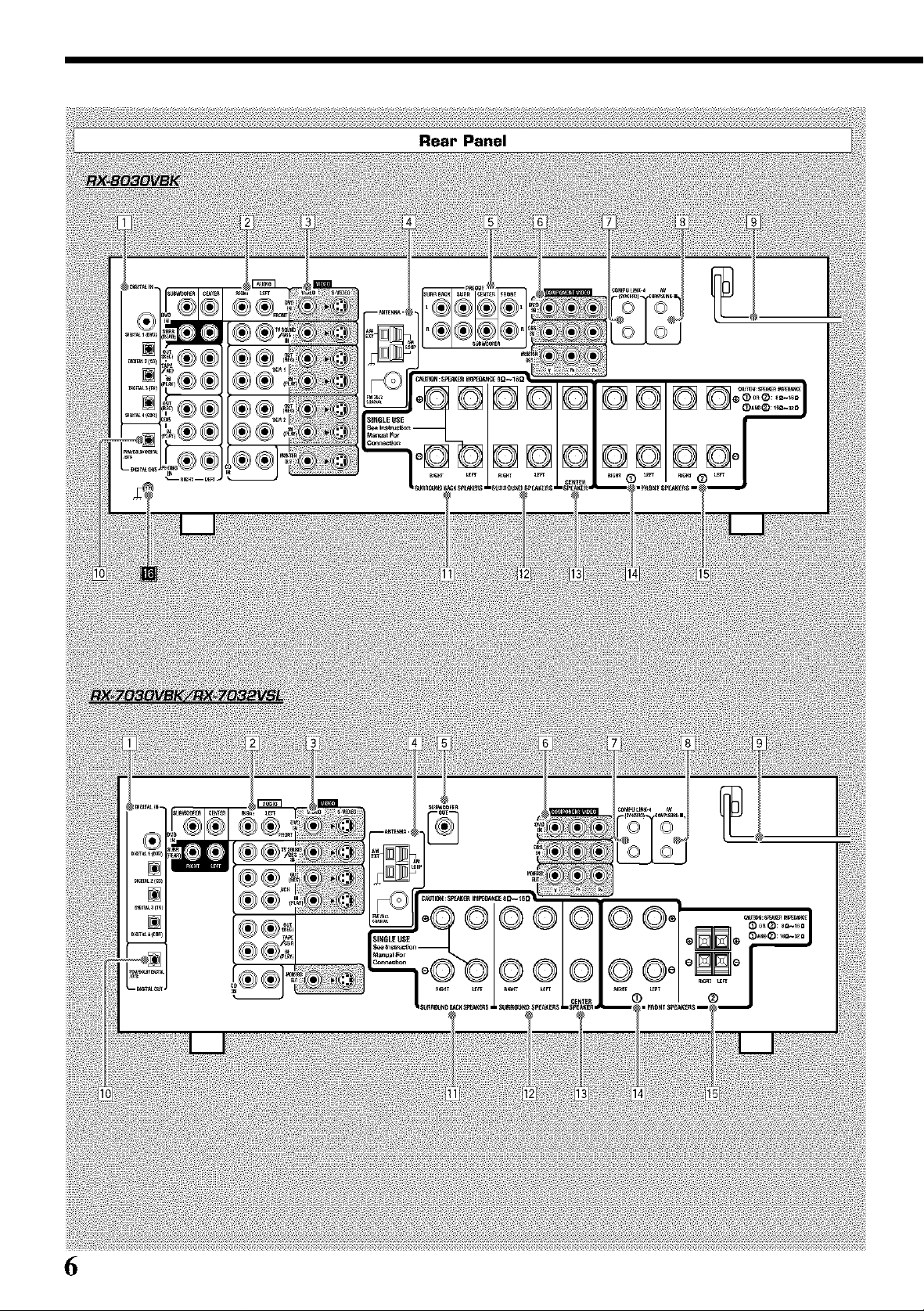
Rear Panel
RX-BO3OVBK
IT/ DIGITAL IN terminals (16)
• Coaxial: DIGITAL I (DVD)
• Optical: DIGITAL 2 (CD), DIGITAL 3 (TV),
DIGITAL 4 (CDR)
12/ AUDIO inpul!oulput jacks (11 - 15)
• Input: DVD IN FRONT, CENTER, SUBWOOFER,
SURR (REAR), TV SOUND/DBS IN,
VCR I IN (PLAY), VCR 2 IN (PLAY), CD IN,
TAPE/MD IN (PLAY), CDR IN (PLAY),
PHONO IN
• Output: VCR I OUT (REC), VCR 2 OUT (REC),
TAPE/MD OUT (REC), CDR OUT (REC)
13/ S-VIDEO and composite VIDEO inpul!oulput jacks (14, 15)
• Input: DVD IN, TV SOUND/DBS IN, VCRI IN (PLAY),
VCR 2 IN (PLAY)
• Output: VCR I OUT (REC), VCR 2 OUT (REC),
MONfrOR OUT
141 FM/AM ANTENNA terminals (8)
[5/ PREOUTjacks (10, 11)
• FRON'I; CENTER, SUBWOOFER, SURR, SURR BACK
[g/ COMPONENT VIDEO input!oulput jacks (14, 15)
• Input: DVD IN, DBS IN
• Output: MONITOR OUT
17J COMPU LINK-4 (SYNCHRO) terminals (41)
181 AV COMPULINK-III terminals (42)
[9_ AC power cord (16)
[10J DIGITAL OUT terminal (16)
1ill SURROUND BACK SPEAKERS terminals (10)
112_SURROUND SPEAKERS terminals (10)
113]CENTER SPEAKER lerminals (10)
114JFRONT SPEAKERS (1) terminals (10)
1151FRONT SPEAKERS _2) terminals (10)
[] Earth (ground) terminal (11)
RX-703OVBK/RX-7032VSL
DIGITAL IN terminals (16)
• Coaxial: DIGITAL I (DVD)
• Oplical: DIGITAL 2 (CD), DIGITAL 3 (TV),
DIGITAL 4 (CDR)
/2 AUDIO input/output jacks (12- 15)
• Input: DVD IN--FRONT, CENTER, SUBWOOFER,
SURR (REAR), TV SOUND/DBS IN,
VCR IN (PLAY), TAPE/CDR IN (PLAY), CD IN
• Oulput: VCR OUT (REC), TAPE/CDR OUT (REC)
/3 S-VIDEO and composile VIDEO inpul/output jacks (14, 15)
• Input: DVD IN, TV SOUND/DBS IN, VCR IN (PLAY)
• Oulput: VCR OUT (REC), MONITOR OUT
//(] FM/AMANTENNA lerminals (8)
/5] SUBWOOFER OUT jack (10)
/g COMPONENTVIDEO inpul/outputjacks (14, 15)
• Input: DVD IN, DBS IN
• Oulput: MONITOR OUT
/7] COMPU LINK-4 (SYNCHRO) lerminals (41)
/8] AV COMPULINK-III lerminals (42)
/9] AC power cord (16)
/10] DIGITAL OUT terminal (16)
/11] SURROUND BACK SPEAKERS terminals (10)
/f2] SURROUND SPEAKERS lerminals (10)
/1)] CENTER SPEAKER terminals (10)
/1_(]FRONT SPEAKERS @ lerminals (10)
/fS[ FRONT SPEAKERS (2) lerminals (10)
Differences between RX-803OVBK and RX-703OVBK/RX-7032VSL ©: Supplied x : Not supplied
_-- Video jacks (input/output) PREOUT jacks CC Converter Selectable source
RX-8030VBK Composite video (4/3) DVD MULTI, DVD, VCR 1, VCR 2, VIDEO,
S-video (4/3) O Q) TV SOUND/DBS, PHONO, CD, CDR, TAPE/MD,
Component video (2/1) FM, AM
RX-7030VBK Composite video (3/2) DVD MULTI, DVD, VCR,
RX-7032VSL S-video (3/2) x × TV SOUND/DBS, CD, TAPE/CDR, FM, AM
Component video (2/1)
Remote Control DisplayWindow Color
RM-SRX8030J Q Black
RM-SRX7030J x Black
RM-SRX7032U x Silver
7
Page 10
Getting Started
This section explains how to connect audio/video components and speakers to the receiver, and how to connect the
power supply,
If the remote control cannot transmit signals or operate the receiver
correctly, replace the baneries. Use two R6P(SUM-3)/AA(I 5F) type
General Precautions
• Be sure your hands are dry.
• Turn the power off to all components.
• Real the manuals supplied with the components you are going to
connect.
Locations
• Install the receiver in a location that is level and protected from
moisture,
• The temperature around the receiver must be between -5°C and
35°C (23°F and 95°F ).
• Make sure there is good ventilation around the receiver, Poor
ventilation could cause overheating and damage the receiver.
Handling the receiver
• Do not insert any metal object into the receiver.
• Do not disassemble the receiver or remove screws, covers, or
cabinet.
• Do not expose the receiver to rain or moisture.
dry-cell baneries.
Notes:
• Suppliedbatteriesarefortheinitialsetup. Replaceforcontinued
use,
• After replacing the batteries, set the manufacturers'codes again
(see pages from 47 to 49),
CAUTION:
Follow these precautions to avoid leaking or cracking cells:
• Place batteries in the remote control so they match the polarity:
(+) to (+) and (-) to (-),
• Use the correct type of batteries. Batteries that look similar may
differ in voltage,
• Always replace both batteries at the same time.
• Do not expose batteries to heat or flame.
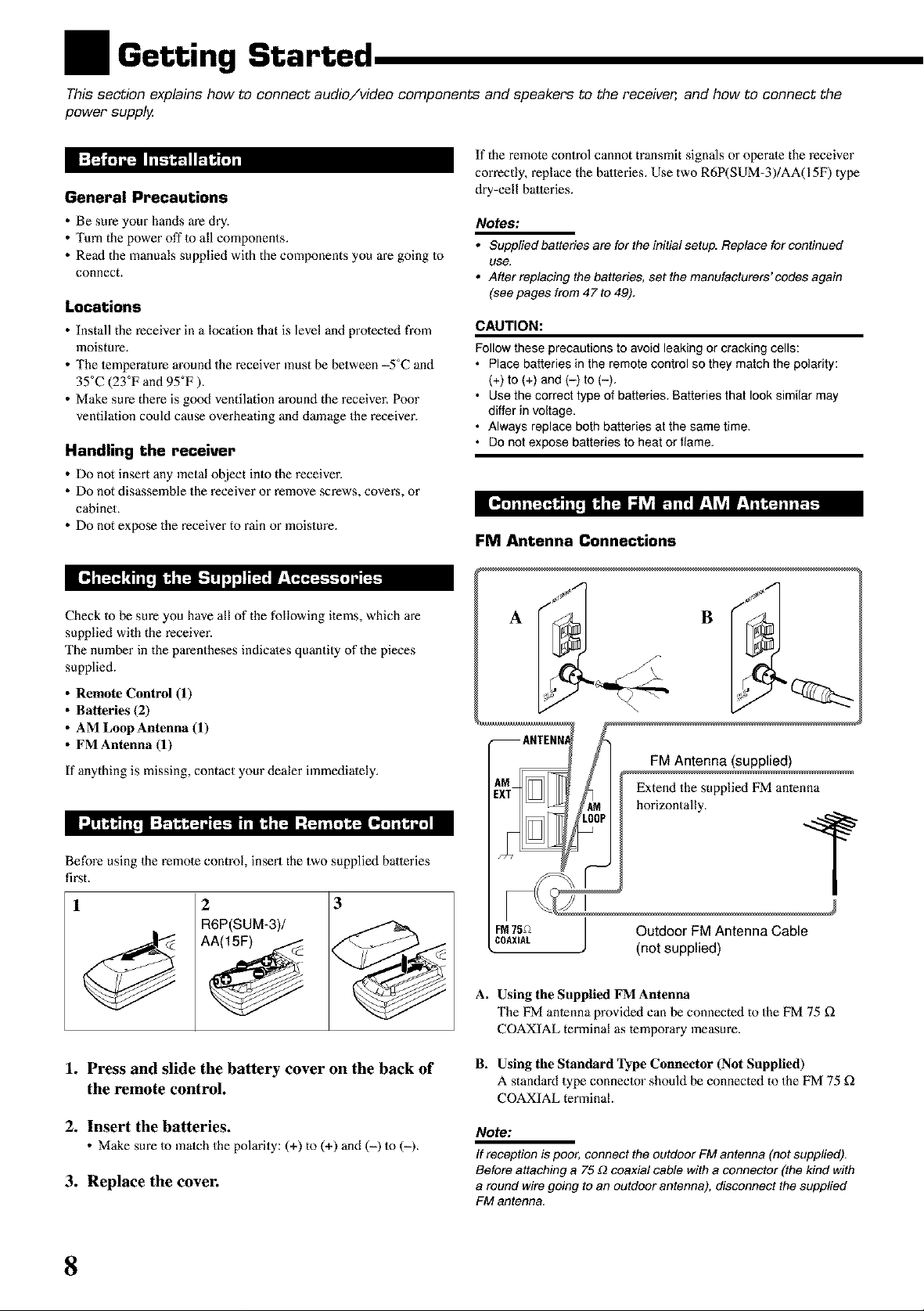
FM Antenna Connections
Check Io be sure you have all of the following items, which are
supplied with the receiver.
The number in the parentheses indicates quanthy of the pieces
supplied.
• Remote Control (1)
• Batteries (2)
• AM LoopAntenna (1)
• FM Antenna (1)
If anything is missing, contact your dealer immediately.
Before using the remote control, insert the two supplied baneries
first.
1 2
R6P(SUM-3)/
3
1. Press and slide the battery cover on the back of
the remote control.
FM75,_ / Outdoor FM Antenna CaNe
COAXIAL J (not supplied)
A. Using the Supplied FM Antenna
The FM antenna provided can be connected to the FM 75 £_
COAXIAL terminal as temporary measure.
B. Using the Standard l_pe Connector (Not Supplied)
A standard type connector should be connected to the FM 75 £_
COAXIAL terminal
/
2. Insert the batteries.
• Make sure to match thepolarity: (+) to (+) and (-) to (-).
3. Replace the cover.
8
Note:
If reception is poor, connect the outdoor FM antenna (not supplied).
Before attaching a 75 £2coaxial cable with a connector (the kind with
a round wire going to an outdoor antenna), disconnect the supplied
FM antenna.
Page 11
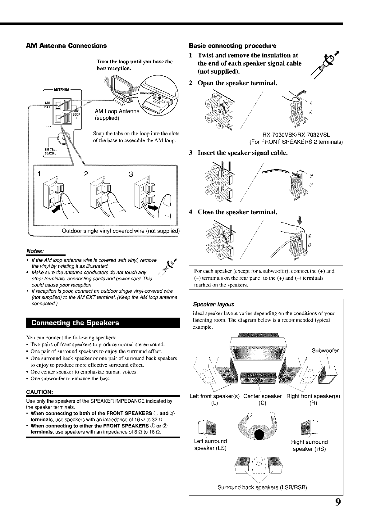
AM Antenna Connections
Turn the loop until you have the
best reception.
Basic connecting procedure
1 Twist and remove the insulation at
the end of each speaker signal cable
(not supplied).
2 Open the speaker terminal.
Snap the tabs on the loop into the slols
of 1he base to assemble the AM loop.
3
Notes:
• If the AM loop antenna wire is covered with vinyl, remove
the vinyl by twisting it as illustrated,
• Make sure the antenna conductors do not touch any
other terminals, connecting cords and power cord. This
could cause poor reception,
• ff reception is poor, connect an outdoor single vinyl-covered wire
(not supplied) to the AM EXT terminal (Keep the AM loop antenna
connected,)
You can connect the following speakers:
• Two pairs of front speakers to produce normal s_ereo sound.
• One pair of surround speakers to enjoy the sun'ound effect.
• One sun'ound back speaker or one pair of surround back speakers
to enjoy to produce more effective surround effect.
• One ccnler speaker to emphasize human voices.
• One subwoofer to enhance the bass.
RX-7030VBK/RX-7032VSL
(For FRONT SPEAKERS 2 terminals)
3 Insert the speaker signal cable.
4 Close the speaker terminal.
For each speaker (excepl for a subwoofer), connect the (+) and
(-) lerminals on the rear panel to the (+) and (-) terminals
marked on the speakers.
Speaker laveut
Ideal speaker layout varies depending on 1he conditions of your
lislening room. The diagram below is a recommended typical
example.
Subwoofer
CAUTION:
Use only the speakers of the SPEAKER IMPEDANCE indicated by
the speaker terminals.
• When connecting to both of the FRONT SPEAKERS _1 and _2_
terminals, use speakers with an impedance of 16 _ to 32 _.
• When connecting to either the FRONT SPEAKERS _1 or _z_
terminals, use speakers with an impedance of 8 _ to 16 _.
Left front speaker(s) Center speaker Right front speaker(s)
(L) (C) (R)
Left surround Right surround
speaker (LS) speaker (RS)
Surround back speakers (LSB/RSB)
9
Page 12
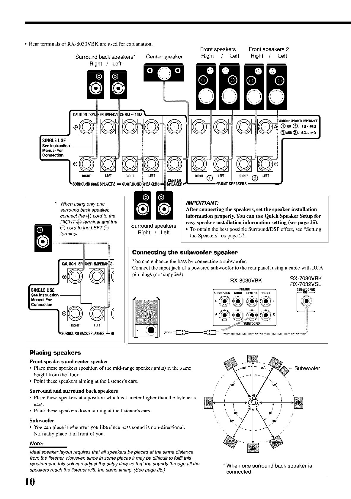
• Rein" terminals of RX-8030VBK are used for explanation.
Surround back speakers*
Right / Left
Center speaker
Front speakers 1 Front speakers 2
Right / Left Right / Left
SINGLE USE
Manual For
Connection
RIGHT LEFT
SURROUND_Q( SPEAKERS•
* When using only one
surround back speaker,
connect the (_ cord to the
RIGHT _ terminal and the
cord to the LEFT _
terminal
LKERtMPEDA
I//1-_\\1
I\\v//I
RIGHT LEFT
SURROUNDBACKSPEAKERS,
_TER
FRONT SPEAKERS
IMPORTANT:
After connecting tile speakers, set the speaker installation
information properly. You can use Quick Speaker Setup for
Surround speakers
Right / Left
easy speaker installation information setting (see page 25).
• "Ib obtain the best possible Surround/DSP effect, see "Setting
the Speakers" on page 27.
Connecting the subwoofer speaker
You can enhance the b_s by connecting a subwoofeE
Connect the input jack of a powered subwoofer Io the rear panel, using a cable with RCA
pin plugs (not supplied).
RX-8030VBK RX-7030VBK
PREOUT SUB_ _FER
[ _f_ SUSWOOFER
RX-7032VSL
Placing speakers
Front speakers and center speaker
• Place these speakers (position of the mid-range speaker units) al the same
height from the floor.
• Point these speakers aiming al the listener's ears.
Surround and surround back speakers
• Place these speakers at a position which is 1 meter higher than the lislener's
ears.
• Point these speakers down aiming al the lislener's ears.
Subwoofer
• You can place it wherever you like since bass sound is non-directional.
Normally place it in front of you.
Note:
Ideal speaker layout requires that all speakers be placed at the same distance
from the llstene_ However, since in some places it may be difficult to fulfil this
requirement, this unit can adjust the delay time so that the sounds through all the
speakers reach the listener with the same timing. (See page 28.)
10
Subwoofer
*When one surround back speakeris
connected.
Page 13
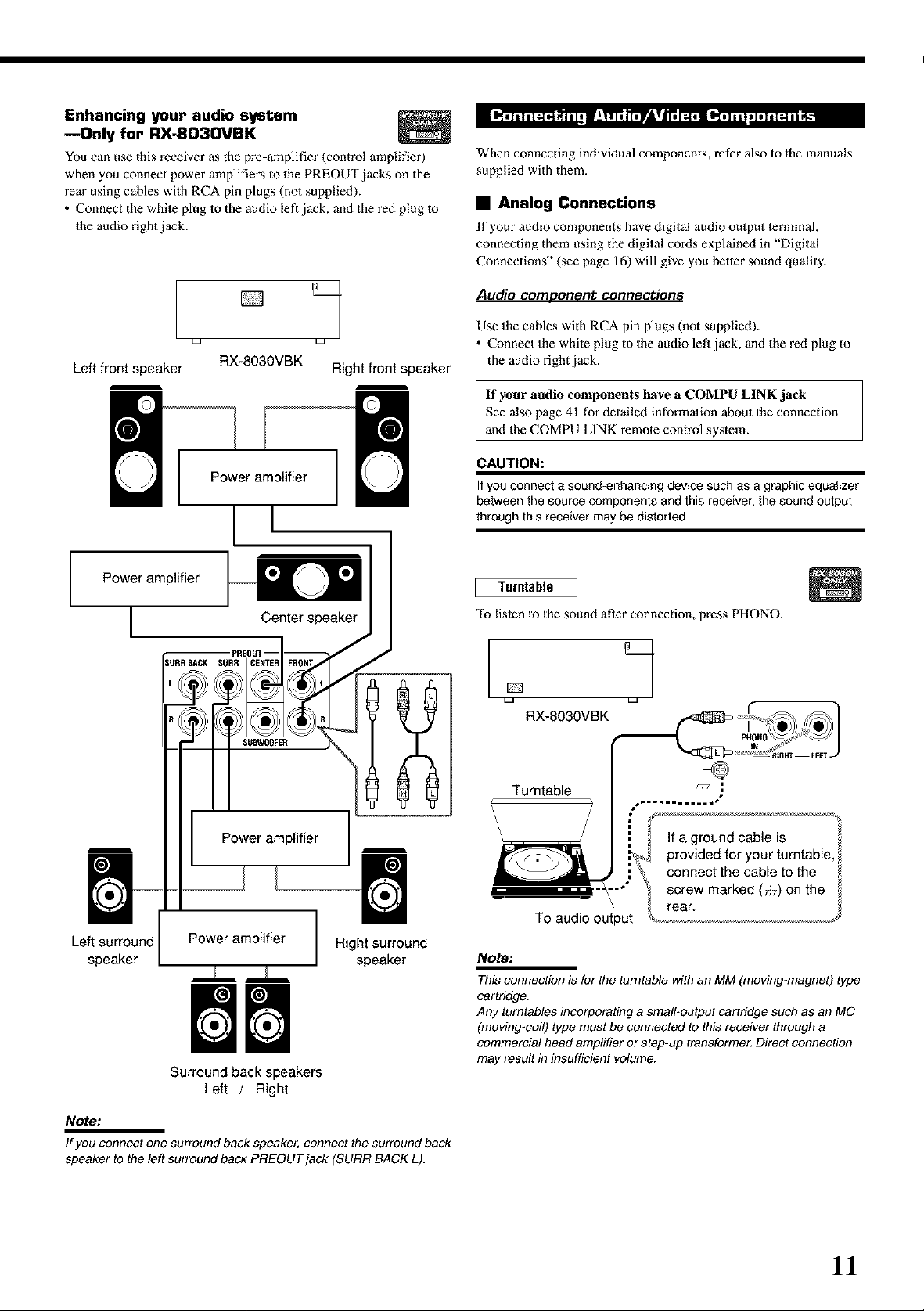
Enhancing your audio system
mOnly for RX-8030VBK
_u can use this receiver _ the p_-_plifier (control amplifier)
when you connect power amplifie_ to thePREOUT jacks on the
rein"using cables with RCA pin plugs (n_ supplied).
• Connect the white plug tothe audio left jack, and the red plug to
the audio right jack.
When connecting individual components, refer also to the manuals
supplied with them.
• Analog Connections
If your audio components have digital audio output terminal,
connecting them using the digital cords explained in "Digital
Connections" (see page 16) will give you better sound quality.
Audio COmDor]et_t cor]r]ectior]s
Left front speaker
Power amplifier
[
1
RX-8030VBK Right front speaker
Power amplifier
[l
Center speaker
SUBWOOFER
Use the cables with RCA pin plugs (not supplied).
• Connect the white plug to the audio lefl jack, and the red plug to
the audio right jack.
If your audio components have a COMPU LINK jack
See also page 41 for detailed information about the connection
and the COMPU LINK remote control system.
CAUTION:
If you connect a sound-enhancing device such as a graphic equalizer
between the source components and this receiver, the sound output
through this receiver may be distorted.
Turntable
To listen to the sound after connection, press PHONO.
o 1
_a _a
RX-8030VBK
Power amplifier
Left surround Power amplifier
speaker
Surround back speakers
Left / Right
Note:
If you connect one surround back speaker, connect the surround back
speaker to the left surround back PREOUTjack (SURR BACK L).
Right surround
speaker
Turntable
If a ground cable is
provided for your turntable
connect the cable to the
screw marked (_) on the
rear.
To audio output
Note:
This connection is for the turntable with an MM (moving-magnet) type
cartridge.
Any turntables incorporating a small-output cartridge such as an MC
(moving-coil) type must be connected to this receiver through a
commercial head amplifier or step-up transforme_ Direct connection
may result in insufficient volume.
11
Page 14
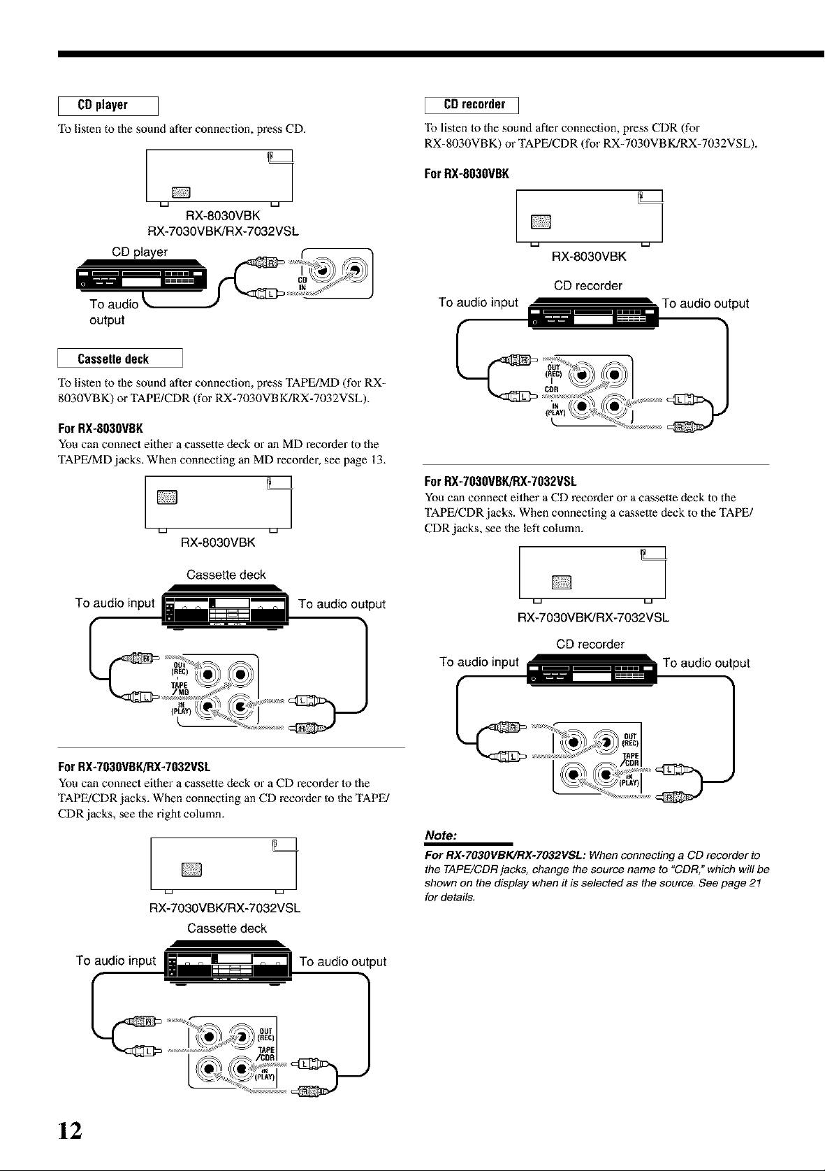
CDplayer
To listen to the sound after connection, press CD.
RX-8030VBK
RX-7030VBK/RX-7032VSL
CD player
output
Cassette deck
"Ib listen to the sound after connection, press TAPE/MD (for RX-
8030VBK) or TAPE/CDR (for RX-7030VBK/RX-7032VSL).
For RX-803OVBK
You can connect either a cassette deck or an MD recorder to the
TAPE/MD jacks. When connecting an MD recorder, see page 13.
1
RX-8030VBK
CD recorder I
"[b listen to the sound after connection, press CDR (for
RX-8030VBK) or TAPE/CDR (for RX-7030VBK]RX-7032VSL).
ForRX-803OVBK
1
RX-8030VBK
CD recorder
For RX-7030VBK/RX-7032VSL
You can connect either a CO rccol'Oer or a cassette deck to the
TAPE/CDR jacks. When connecting a c&ssetle deck to the TAPE/
CDR jacks, see the left column.
Cassette deck
To audio input
For RX-7030VBK/RX-7032VSL
You can connect either a cassette deck or a CD recorder 1o the
TAPE/CDR jacks. When connecting an CD recorder Io 1heTAPE/
CDR jacks, see the right column.
To audio output
1
La La
RX-7030VBK/RX-7032VSL
Cassette deck
To audio input
To audio output
1
RX-7030VBK/RX-7032VSL
CD recorder
To audio input _ _ ,,,,,,,, To audio output
_ OUT
,, (REC)
\_ 1/0[APE
No_:
For RX.TO3OVBK/RX-7032VSL: When connecting a CD recorderto
the TAPE/CDR jacks, change the source name to "CDR." which will be
shown on the display when it is selected as the source. See page 21
for details.
12
Page 15
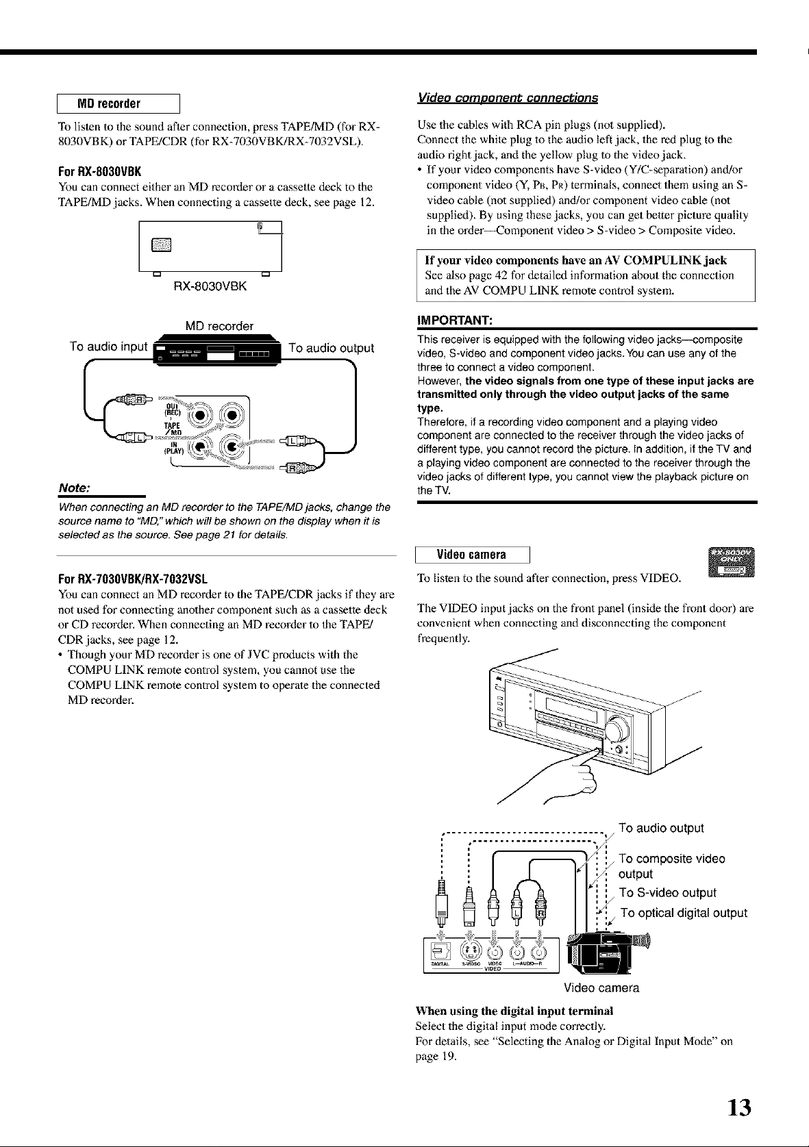
MD recorder
"lb listen 1o the sound after connection, press TAPE/MD (for RX-
8030VBK) or TAPE/CDR (for RX-7030VBK/RX-7032VSL).
ForRX-8030VBK
You can connect either an MD recorder or a c_sette deck to the
TAPE/MD jacks. When connecting a cassette deck, see page 12.
Video comoorlent connections
Use the cables with RCA pin plugs (no1 supplied).
Connect the white plug 1othe audio left jack, the red plug to the
audio right jack, and the yellow plug 1o the video jack_
• If your video components have S-video (Y/C-separalion) and!or
component video (Y, PB,PR) terminals, connect them using an S-
video cable (no1 supplied) and/or component video cable (no1
supplied). By using these jacks, you can get belier picture quality
in the order--Component video > S-video > Composite video.
D
RX-8030VBK
MD recorder
To audio input _ ...... To audio output
Note:
When connecting an MD recorder to the TAPE/MD jacks, change the
source name to "MD," which will be shown on the display when it is
selected as the source. See page 21 for details,
For RX-7030VBK/RX-7032VSL
You can connect an MD recorder to the TAPE/CDR jacks if they are
not used for connecting anolher component such as a cassette deck
or CD recorder. When connecting an MD recorder Io 1he TAPE/
CDR jacks, see page 12.
• Though your MD recorder is one of JVC products with the
COMPU LINK remote control system, you cannot use the
COMPU LINK remote control system to operate the connected
MD recorder.
If your video components have an AV COMPULINK jack
See also page 42 for detailed information about the connection
and the AV COMPU LINK remote control system.
iM PORTANT:
This receiver is equipped with the following video jacks--composite
video, S-video and component video jacks. You can use any of the
three to connect a video component.
However, the video signals from one type of these input jacks are
transmitted only through the video output jacks of the same
type.
Therefore, if a recording video component and a playing video
component are connected to the receiver through the video jacks of
different type, you cannot record the picture. In addition, if the TV and
a playing video component are connected to the receiver through the
video jacks of different type, you cannot view the playback picture on
the TV.
Video camera
To listen to the sound after connection, press VIDEO.
The VIDEO input jacks on the front panel (inside the front door) are
convenient when connecting and disconnecting the component
frequently.
.... _-..................... .-._/
To audio output
output
f j To composite video
_ To S-video outputTo optical digital output
Video camera
When using the digital input terminal
Select the digital input mode con'ectly.
For details, see "Selecting the Analog or Digital Input Mode" on
page 19.
13
Page 16
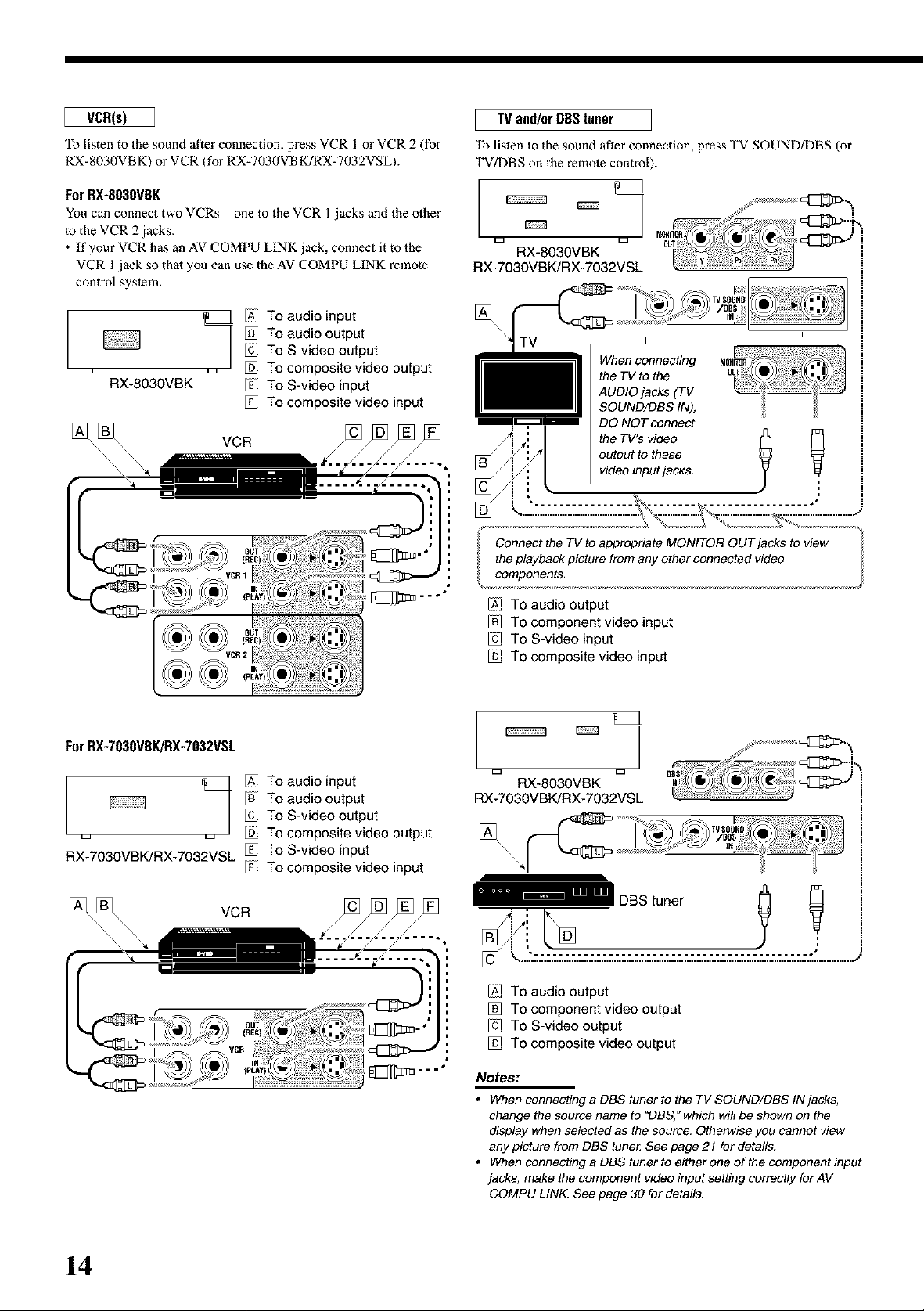
VCR(s)
"Ib listen to the sound after connection, press VCR I or VCR 2 (for
RX-8030VBK) or VCR (for RX-7030VBK/RX-7032VSL).
For RX-803OVBK
You can connect two VCRs--one 1o the VCR l jacks and the other
Io the VCR 2 jacks.
• If your VCR has an AV COMPU LINK jack, connect it to the
VCR I jack so thai you can use the AV COMPU LINK remote
control system.
TV and/or DBStuner
"[b listen to the sound after connection, press TV SOUND/DBS (or
TV/DBS on the remote control).
RX-8030VBK
RX-7030VBK/RX-7032VSL
/Al To audio input
To S-video output
,_ ,_ _ To composite video output
RX-8030VBK _ To S-video input
For RX-7030VBK/RX-7032VSL
_ To audio output
To composite video input
VCR
[]
TV
When connecting
the TV to the
AUDIO jacks (TV
SOUND/DBS IN),
DO NOT connect
the TV's video
[]
Connect the TV to appropriate MONITOR OUT jacks to view
the playback picture from any other connected video
components,
[AI TO audio output
To component video input
To S-video input
To composite video input
output to these
video input jacks,
Y
/Al To audio input
To S-video output
,_ ,_ _ To composite video output
RX-7030VBK/RX-7032VSL _ To S-video input
I _ To audio output
To composite video input
VCR
RX-8030VBK
RX-7030VBK/RX-7032VSL
[A] TO audio output
To component video output
To S-video output
To composite video output
Notes:
• When connecting a DBS tuner to the TV SOUND/DBS IN jacks,
change the source name to "DBS," which wil! be shown on the
display when selected as the source, Otherwise you cannot view
any picture from DBS tune_ See page 21 for details.
• When connecting a DBS tuner to either one of the component input
jacks, make the component video input setting correctly for AV
COMPU LINK. See page 30 for details.
14
Page 17
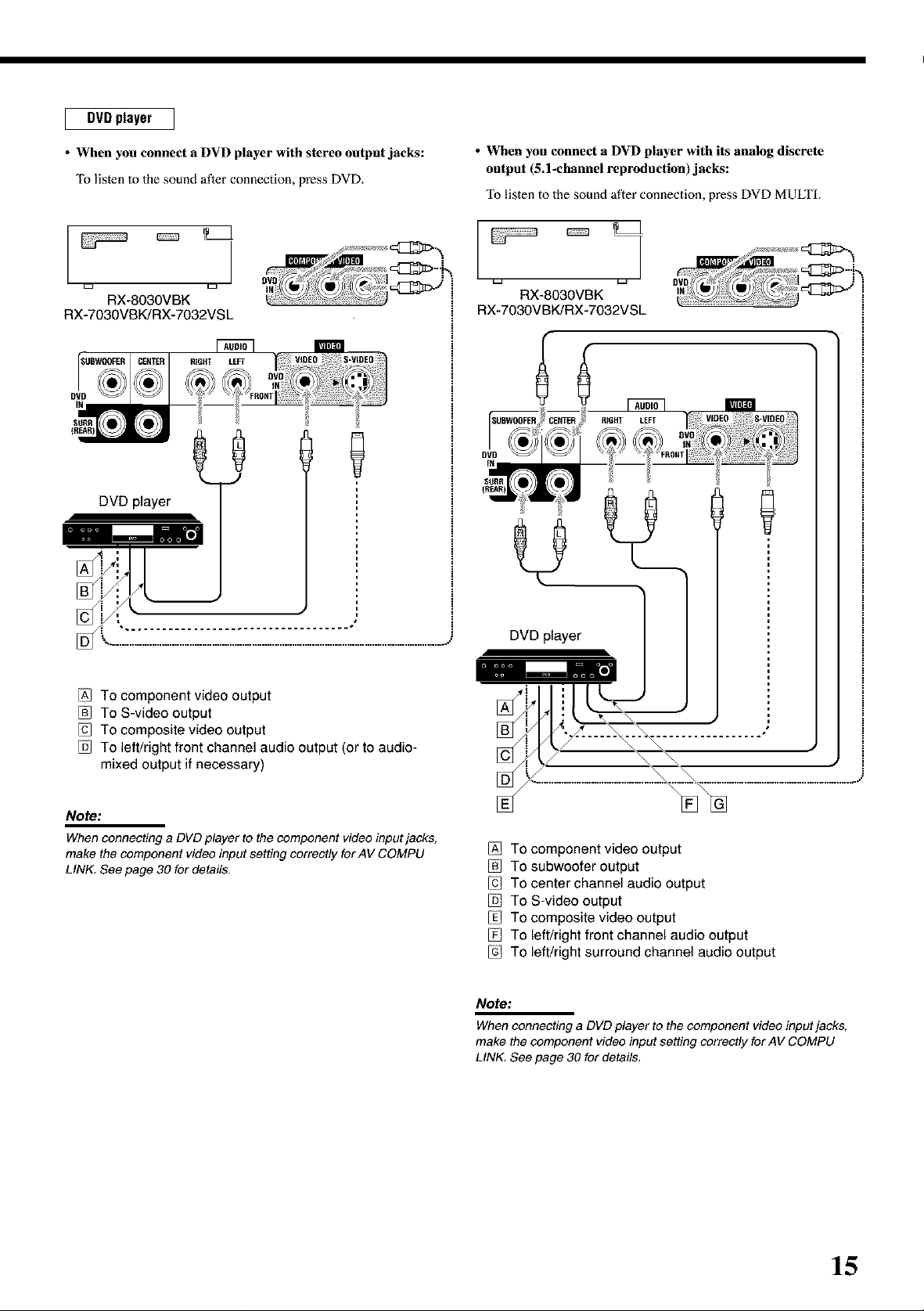
DVD player
• When you connect a DVD player with stereo output jacks:
To listen to the sound after connection, press DVD.
RX-8030VBK RX-8030VBK
RX-7030VBK/RX-7032VS L RX-7030VBK/RX-7032VSL
• When you connect a DVD player with its analog discrete
output (5.1-channel reproduction)jacks:
To listen to the sound after connection, press DVD MULTI.
DVD player
[
/A] To component video output
To S-video output
To composite video output
To left/right front channel audio output (or to audio-
mixed output if necessary)
Note:
When connecting a DVD player to the component video input jacks,
make the component video input setting correctly for AV COMPU
LINK, See page 30 for details.
/A] To component video output
To subwoofer output
To center channel audio output
To S-video output
To composite video output
To left/right front channel audio output
To left/right surround channel audio output
Note:
When connecting a DVD player to the component video input jacks,
make the component video input setting correctly for AV COMPU
LINK See page 30 for details,
15
Page 18
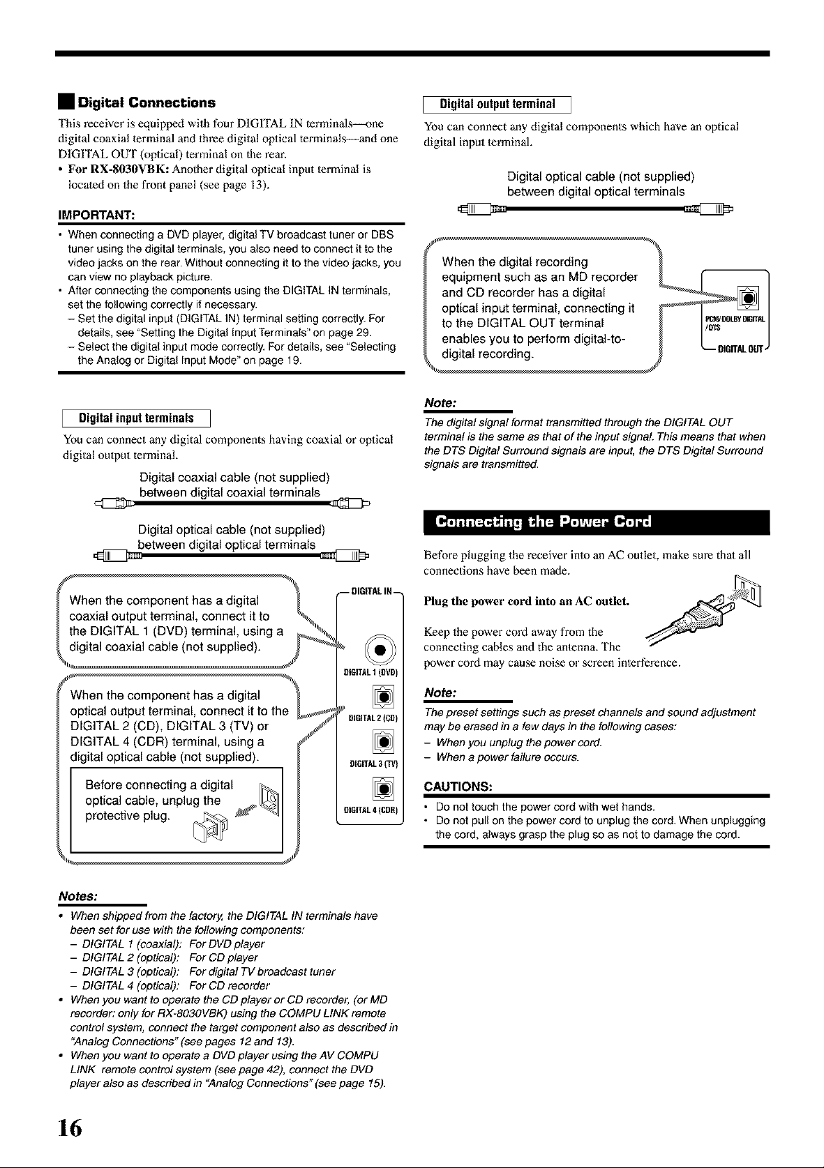
• Digital Connections
This receiver is equipped with four DIGITAL IN terminals--one
digital coaxial lerminal and three digital oplical terminals--and one
DIGITAL OUT (oplical) terminal on the rear.
• For RX-8030VBK: Another digital oplical input lermina[ is
located on the front panel (see page 13).
IMPORTANT:
• When connecting a DVD player, digital TV broadcast tuner or DBS
tuner using the digital terminals, you also need to connect it to the
video jacks on the rear. Without connecting it to the video jacks, you
can view no playback picture.
• After connecting the components using the DIGITAL IN terminals,
set the following correctly if necessary.
- Set the digital input (DIGITAL IN) terminal setting correctly. For
details, see "Setting the Digital Input Terminals" on page 29.
- Select the digital input mode correctly. For details, see "Selecting
the Analog or Digital Input Mode" on page 19.
Digital input terminals
You can connect any digital components having coaxial or opiical
digital ouiput terminal.
Digital coaxial cable (not supplied)
between digital coaxial terminals
Digital outputterminal
You can connect any digital components which have an optical
digital input lerminal.
Digital optical cable (not supplied)
between digital optical terminals
\
When the digital recording
equipment such as an MD recorder _ ['- "]
and CD recorder has a digital _ |
optical input terminal, connecting it _ ] _ |
to the DiGiTAL OUT terminal I
enables you to perform digital-to- I I /
digital recording. J _-- umrrAL0trr_
qll
Note:
The digital signal format transmitted through the DIGITAL OUT
terminal is the same as that of the input signal This means that when
the DTS Digital Surround signals are input, the DTS Digital Surround
signals are transmitted.
Digital optical cable (not supplied)
between digital optical terminals
--DIGITALIN_
OiGITALI(OVD)
optical _minal, connect it to the
DIGITAL 2 (CD), DiGiTAL 3 (TV) or f
DIGITAL 4 (CDR) terminal, using a
digital optical cable (not supplied).
DIGITAL2{CO)
9IGITAL3(TV)
o yr C°2eeC2 tih ie
OlGITAL4ICOR)
protective plug. [_ _
I
Notes:
• When shipped from the factory, the DIGITAL IN terminals have
been set for use with the following components:
- DIGITAL I (coaxial): For DVD player
- DIGITAL 2 (optical): For CD player
- DIGITAL 3 (optical): For digital TV broadcast tuner
- DIGITAL 4 (optical): For CD recorder
• When you want to operate the CD player or CD recorder, (or MD
recorder: only for RX-803OVBK) using the COMPU LINK remote
control system, connect the target component also as described in
"Analog Connections" (see pages 12 and 13).
• When you want to operate a DVD player using the AV COMPU
LINK remote control system (see page 42), connect the DVD
player also as described in "Analog Connections" (see page 15).
Before plugging the receiver inlo an AC outlet, make sure thai all
connections have been made.
Plug the power cord into an AC outlet.
Keep the power cord away from the
connecting cables and the anlenna. The
power cord may cause noise or screen inlerference.
Note:
The preset settings such as preset channels and sound adjustment
may be erased in a few days in the following cases:
- When you unplug the power cord.
- When a power failure occurs.
CAUTIONS:
• Do not touch the power cord with wet hands.
• Do not pull on the power cord to unplug the cord. When unplugging
the cord, always grasp the plug so as not to damage the cord.
16
Page 19

Basic Operations
The following operations are commonly used when you play any sound sources.
©
Press one of the source selection buttons.
1 Turn on the power.
• See "Turning On the Power" below.
2 Select the source.
• See "Selecting the Source Io Play" to the right.
3 Adjust the volume.
• See "Adjusting the Volume" on page 18.
4 Select the surround or DSP modes.
• See "Activating the Surround Modes" (page 37) and
-*,.ctivating the DSP Modes" (page 39).
• The selected source name and the previously selected Surround/
DSP mode also appear on the display.
Selected source name and current
Surround/DSP mode appear.
_,_rmz_v_l.,.,...,-=it..t...,-=t--%...............
[] S []_ IIII III III Ill III III Ill III III Ill
[][][] / 4..lll. / vo.aa
For RX-8030VBK
D D D D
E ] c:z
io ooo..... io
o©: =
_====2
IIII ill III Ill ill III Ill ill III Ill _.P_TAn
rill [']Tl[qI'_il :.I_T'I_
L====5 L====J
Press 0/I STANDBY/ON (or AUDIO 0/I on the remote
control).
The STANDBY lamp goes of£ The name of the current source and
Surround/DSP mode appear on the display.
Current source name and Surround/DSP mode appear
[] []
!..' _,s !,.s
f',, i ir'.. [
[:-:L" ii: C.'F F::l
Current volume [eve[appears.
To turn off the power (into standby mode),
press eli STANDBY/ON (or AUDIO 0/I on the remote control)
again.
The STANDBY [amp lights up.
Note:
A small amount of power is consumed in standby mode. To turn off
the power completely, unplug the AC power cord.
On the unit
• The lamp on the selected source lights up (ex. when DVD is
selected as the source).
DV3 MULTI
VCR_ VCR2 COR TAPE/MD
_//D_£ VlDC 0 PUONO
On the remote
For RX.7030VBK/RX-7032VSL
On the unit
DUD MULTI DUD CD FM/AM
TVfDBS (_ TA_BL'_
C _ C _
On the remote
Notes:
• For RX-803OVBK: When connecting an MD recorder (to the TAPE/
MD jack) and a DBS tuner (to the TV SOUND/DBS jacks), change
the source names shown on the displa_z For details, see page 21.
• For RX-TO3gVBK/RX-TO32VSL: When connecting an CD recorder
(to the TAPE/CDR jacks) and a DBS tuner (to the TV SOUND/DBS
jacks), change the source names shown on the displa_z For details,
see page 21.
17
Page 20

Speaker and signal indicators on the display
By checking the following indicators, you can e_ily confirm which
speakers you are activating and which signals m'e coming into this
receiver.
Speaker indicators
DDD
[suBwF.]
Signal indicators
L R
LFE
D D
DDD
What speaker indicators light depends on the speaker setting
(for details, see "Setting the Speakers" on page 27).
• The frames of "L" "C," "R," "LS," "RS," and "SB" light up,
when the corresponding speakers are set 1o"LARGE" or
"SMALL" and when the speaker is required for 1heSurround/DSP
mode currently seleeled.
• When "SUB WOOFER" is set to "YES," _ lights up (see
page 27).
• All three frames on the row of "SB" are not used al the same time.
When "SBACK OUT" is set 1o"2SPK," the left and the right ones
are used. When it is set Io "1SPK," the middle one is used (see
page 27).
Selecting different sources for picture and
sound
While watching pictures from a video source, you can listen to
sound of an audio source.
• Once you have selected a video source, pictures of the selected
source are sent to the TV until you select another video source.
Press one of the audio source selection buttons while viewing the
picture from a video component such as the VCR or DVD
player, etc.
For RX.8030VBK cD _v_
D D D D [3 [3 CDR TAP_MD
On the unit On the remote
For RX.7030VBK/RX-7032VSL
On the unit
Note:
When you see the picture through the COMPONENT VIDEO jacks,
you cannot use this function.
On the remote
C )
C)
p_NO
c>
(_CD) PM/AM
TApF_COR
The signal indicators light up to show the incoming signals.
L: • When digital input is selected: Lights up when the [eft
channel signal comes in.
•When analog input is selected: Always lighls up.
R: •When digital input is selected: Lights up when the right
channel signal comes in.
•When analog input is selected: Always lighls up.
C: Lights up when the center channel signal comes in.
LFE: Lights up when the LFE channel signal comes in.
kS: Lights up when the left surround channel signal comes in.
RS: Lights up when the right sun'ound channel signal comes in.
S: Lights up when the monaural surround channel signal
comes in.
SB: Lights up when the surround back channel signal comes in.
Note:
When "DVD MULTI" is selected as the source, "t_,""C," "R," "LFE," "LS,"
and "RS" light up.
How to understand the soeaker and sienal indicator
illumination
FncEN
[suBwF.],
SB
Ex. No sound comes out of the
center speaker and surround
back speakers though center
channel and surround back
channel signals are coming
into this receiver.
L_J L_J
On the front eaneh
To increase the volume, turn MASTER VOLUME clockwise.
To decrease the volume, turn it counlerc[ockwise.
From the remote control:
To increase the volume, press VOLUME +.
To decrease the volume, press VOLUME -.
CAUTION:
Always set the volume to the minimum before starting any sources. If
the volume is set at its high level, the sudden blast of sound energy
can permanently damage your hearing and/or ruin your speakers.
Notes:
• The volume level can be adjusted within the range of"O" (minimum)
to "70" (maximum).
• ffyou set One Touch Operation to "ON"(see page 30), you do not
have to adjust the volume level each time you change the source. It
is automatically set to the stored level.
18
Page 21

When you have connected two pairs of the front speakers, you can
select which to use.
E
o
[1©o ==
L====J L=====J
To use the speakers connected to the FRONT SPEAKERS @
terminals, press SPEAKERS ON/OFF 1 so that the SPEAKERS 1
indicator lights up on the display. Make sure that the SPEAKERS 2
indicator is not lit on the display.
To use the speakers connected to tile FRONT SPEAKERS @
terminals, press SPEAKERS ON/OFF 2 so that SPEAKERS 2
indicator lights up on the display. Make sure that the SPEAKERS 1
indicator is not lit on the display.
To use both sets of the speakers, press SPEAKERS ON/OFF 1 and
SPEAKERS ON/OFF 2 so thai Ihe SPEAKERS 1/2 indicators light
up on the display.
To use neither sets of the speakers, press SPEAKERS ON/OFF 1
and SPEAKERS ON/OFF 2 so that the SPEAKERS 1/2 indicators
go off from the display.
The HEADPHONE indicator lights up and "HEADPHONE"
appears on the display.
• Activating the speakers turns on the Surround and DSP modes
previously selected.
You can cancel the subwoofer sound even though you have
connecled a subwoofer and have set "SUB WOOFER" m "YES"
(see page 27). This is useful when enjoying surround sound at night.
L====A L===J
Press SUBWOOFER OUT ON/OFF to cancel the subwoofer
sound output.
Each time you press the button, subwoofer sound oulput is
deactivated ("SUBWFR OFF'') and activated ("SUBWFR ON")
alternately.
• When subwoofer sound output is activated, subwoofer oulput level
can be adjusted using the remote control.
1 Press SOUND.
2 Press SUBWOOFER.
3 Press LEVEL + or- to adjust the oulput level
(-10 dB to +lO dB).
Note:
You cannot deactivate the subwoofer sound output when you set
"SMALL" for the front speakers on the Speaker size setting (see page
27) or Quick Speaker Setup (see page 25).
Listenino with headphones onlw
Deactivate both sets of the front speakers, anti connect headphones
to the PHONES jack.
You can enjoy the sound effects through the headphones when
Surround or DSP mode is activated--3D HEADPHONE
(3D H PHONE) mode.
• "3D H PHONE" appears on the display and the DSP and
HEADPHONE indicator lights up on the display. (For details, see
page 36.)
Note:
When you select "DVD MULTI" as the source or any one of the
Surround/DSP mode which activates the center and/or surround
speaker(s), you can use only one set of the speakers,
CAUTION:
Be sure to turn down the volume:
• Before connecting or putting on headphones, as its high volume can
damage both the headphones and your hearing,
• Before turning on speakers again, as its high volume may come out
of the speakers.
When you have connected digital source components using the
digital terminals (see page 16), change the input mode for these
components to the digital input mode.
Before you start, remember...
The digital input terminal setting should be correctly done for
the sources you want to select the digital input mode (see
"Setting the Digital Input Terminals" on pages 29 and 30).
1. Press one of the source selection buttons for which you
want to change the input mode.
• For RX.8030VBK: DVD, VIDEO, TV (SOUND)/DBS,
CD, CDR, or TAPFJMD*
• For RX-7030VBK/RX-7032VSL:
DVD, TV (SOUND)/DBS, CD, or
TAPE/CDR*
* If"TAPE"is selected as the source, digitalinput mode is not
available. To change the source name, see '_Changing the Source
Name" on page 21.
Continued on the next page
19
Page 22

2. Press INPUT DIGITAL (or ANALOG/DIGITAL
INPUT on the remote control) to select "DGTL
AUTO."
The DIGITALAUTO indicator lights up on the display.
[][][] i", i i r'_
[] [] l';gl rl .'.'l I"I ;l .... 25
[_'-_'_j [',][_ u_,_:_j_]
You can enjoy a powerful sound at night using the Midnight Mode.
• When selecting "DGTL AUTO," the following indicators
indicate the digital signal format of the incoming signal.
[LINEAR PCM]
[ DDDIGITAL ]
[ a¢. ]
No indicator lights up when the receiver cannot recognize the
digital signal format of the incoming signals.
When playing software encoded with the Dolby Digital or DTS,
the following symptoms may occur:
• Sound does noi come out ai the beginning of playback.
• Noise comes out while sem'ching for or skipping chapters or
tracks.
In this case, press INPUT DIGITAL repeatedly to select _]
"DGTL D.D" or "DGTL DTS" while "DGTL AUTO"
still remains on the display.
• As you press INPUT DIGITAL, the input mode changes as
follows:
[33[?3[?3 ,,," ' IF.,
[] [_ r'-, i-. i- i
: Lights up when Linear PCM signals come
in.
: Lights up when Do[by Digital signals
come in.
: Lights up when DTS signals come in.
¢", i i 'T" ¢",
- e5
ego
_====2
Press MIDNIGHT MODE so that "MID NIGHT 1" or "MID
NIGHT 2" appears on the display.
The MIDNIGHT MODE indicator also lights up.
MID NIGHT 1: Select when you want to reduce the dynamic
range a little.
MID NIGHT 2: Select when you want to apply the compress
effect fully (useful at midnight).
MID NIGHT OFF: Select when you want to enjoy surround with
its full dynamic range (no effect applied).
Notes:
• IfAna!og Direct is in use, Midnight Mode is temporarily canceled.
• MidnightModeisnotvalidforDVDMULTIplaybackmode.
r_,_j [14_! _
When the input level of the analog source is too high, the sounds
will be distorted. If this happens, you need to attenuate the input
signal level to prevent the sound distortion.
• Once you have made adjustment, it is memorized for each analog
source.
(Digital) (Dolby Digi
F DGTL AUTO*m- DGTL D.D ta_]
When "DGTL D.D" or "DGTL DTS" is selected, the AUTO
indicator goes off, and the corresponding digital signal format
indicator lights up on the display.
• If the incoming signal does not match the selected digital signal
format, the frame of the selected indicator will fl&sh.
Note:
When you turn off the power or select another source, "DGTL 12D"
and "DG TL DTS" settings are canceled and the digital input mode is
automatically reset to "DGTL AUTO."
To select the analog input mode again
Press INPUT ANALOG (or press ANALOG/DIGITAL INPUT on
the remote control repeatedly until "ANALOG" appears on the
display). The ANALOG indicator lights up.
[] [] I=', I I r.
* DGTL DTS +
i il ii i
I-I k i "3 i I"I I"=" _I [_
I I I'I I I I-. '..' '..J _u.E
L====A k=====J
Press and hold INPUT ATT (INPUT ANALOG) so that the
INPUT ATT indicator lights up on the display.
• Each time you press and hold the buiton, the input attenualor
mode turns on ("ATT ON") or off ("NORMAL").
Note:
This function is not valid when DVD MULTI is selected or when
Analog Direct is activated,
20
Page 23

i_j _ ']/'_ [.]11_1 [']ii
You can enjoy the sound closer lo the original source by oven'iding
the sound adjustments such as speaker output level adjustments (see
page 32), Digital Equalization (see page 32), Surround and DSP
modes (see pages 34 to 39), Bass Boost (see page 22) and Midnight
Mode (see page 20). You can only adjust the volume level while
Analog Direct is in use.
• Once you have made adjustment, it is memorized for each analog
source.
I
o
I_©°
L=====J
Press ANALOG DIRECT so that "A DIRECT" appears on the
display.
The lamp on the button also lights up.
• Each time you press the button, Analog Direct turns on and off.
_====2
Notes:
• Whendigitalinputmodeisinuse, AnafogDirectisnotavailable.
• Turning on Surround or DSP mode cancels Analog Direct and
previously selected sound adjustments are recalled.
• If Analog Direct is in use, Midnight Mode is temporarily canceled,
• Turning on Analog Direct cancels Input Attenuator (page 20) (and
CC Converter for RX-803OVBK: below).
When you have connected an MD recorder to the TAPE/MD jacks
or a DBS tuner to the TV SOUND/DBS jacks on lhe rear panel,
change the source name which will be shown on the display.
c:::z
c:::z
c:::3
©
L=====J
I==...... I°0°
L====J
When changing the source name from "TV" to "DBS":
1. Press TV SOUND/I)BS.
• Make sure "TV" appeal's on the display.
2. Press and hold TV SOUND/DBS until "ASSGN DBS"
appears on the display.
_u_oa
[] []
H." -':, "3 i.:i i"i i..: ,--:,"3 vo_ 2 5
Note:
When connecting a DBS tuner to the TV SOUND/DBS IN jacks,
change the source name to +DBS," which will be shown on the display
when selected as the source. Otherwise you cannot view any picture
from DBS tune_
I_v_t__'_ l _ L'_II__"_!IT_ I
JVC's CC (Compensalive Compression) Converter eliminates jilter
and ripples, achieving a drastic reduction in digital distortion by
processing the digital music data in 24 bit-quantization and by
expanding the sampling frequency to 128 kHz (for fs 32 kHz
signals)/176.4 kHz (for fs 44.1 kHz signals)!192 kHz (for fs 48 kHz
signals)+
By using CC Converter, you can obtain a nalural sound field from
both digital and analog sources.
L====J _====J
Press CC CONVERTER so that the lamp on the button lights
up.
• Each time you press the button, CC Converter turns on and off(the
lamp goes oft') alternately.
Note:
You cannot use this function while Analog Direct is in use. If you turn
on Analog Direct while this function is in use, this function will be
canceled.
['or RX-803OVBK:
When changing the source name from "TAPE" to "MD":
1. Press TAPED.
• Make sure "TAPE" appears on the display.
2. Press and hold TAPE/MD until ASSGN MD appears on
the display.
For RX- 7030 VBK/RX- 7032 VSL:
When changing the source name from "TAPE" to "CDR":
1. Press TAPE/CDR.
• Make sure "TAPE" appears on the display.
2. Press and hold TAPE/CDR until "ASSGN CDR" appears on
the display.
To change the source name to TV and TAPE, repeat Ihe
same procedure above.
Note:
Without changing the source name, you can still use the
connectedcomponents, However, there may be some inconvenience.
• For RX.803OVBK:
- "TAPE"or "TV" will appear on the display when you select the MD
recorder or DBS tune_
- You cannot use the digital input (see pages 19and 20) for the
MD recorder.
- You cannot use the COMPU LINK remote control system (see
pages 41) to operate the MD recorder.
• ForRX.TO3OVBK/RX-7032VSL:
- "TAPE"or "TV" will appear on the display when you select the CD
recorder or DBS tune_
- You cannot use the digital input (see pages 19and 20) for the
CD recorde_
21
Page 24

BassReinf°rcingthe _!
Using the Sleep Timer, you can fall asleep while listening to music.
When the shut-off time comes, the receiver turns off aWomatically.
Press SLEEP repeatedly.
The SLEEP indicator lights up on the display, and the shut-off time
changes in 10 minutes inlervals:
Mutingthe
Sound
Using the Sleep
Timer
Changing
the Display
Brightness
Iff_llll_.I_ _ I=!_L'_
You can boost the bass level.
• Once you have made adjustment, it is memorized for each source.
1. Press SOUND.
The 10 keys are activated for sound adjustments.
2. Press BASS BOOST to turn on Bass Boost.
The BASS BOOST indicator lights up.
• Each time you press the button, Bass Boost turns on ("BOOST
ON") and off ("BOOST OFF") a[lernate[y.
For RX-7030VBK/RX-7032VSL:
You can use the BASS BOOST button on 1he front panel.
When the Bass Boost is activated, the lamp on the button lights up.
• Each time you press the button, Bass Boost turns on and off.
Notes:
• This function affects only the sounds from the front speakers,
center speaker, and subwoofe_
• When Analog Direct is in use (see page 21), the Bass Boost is
canceled temporarily,
hY!I!l_ It I'_ l-'ftl'_, I
Press MUTING to mute the sound through all speakers and
headphones connected.
"MUTING" appears an the display and the volume turns oft"(the
VOLUME [eve[ indicator goes off).
To restore the sound, press MUTING again.
• Turning MASTER VOLUME on the front panel or pressing
VOLUME +1- on the remote control also reslores the sound.
You can dim the display.
Press DIMMER.
• Each time you press the button, the brightness
level of the display change as follows:
_Dimmer -_ Much dimmer
Canceled , /
(Normal display)
22
F IO .-- 20 .-- 30 .-- 40.-- 50 .-,-60 .-- 70 .-- 80 .-- 90 --I/
0 (Canceled) , /
To check or change the time remaining until the shut-off time:
Press SLEEP once.
The remaining time until the shut-off time appears in minutes.
• To change the shut-off time, press SLEEP repeatedly.
To cancel the Sleep Timer:
Press SLEEP repeatedly until "SLEEP 0rain" appears on the display.
(The SLEEP indicalor goes off.)
• "Fuming off the power also cancels Ihe Sleep Timer.
Recording a source
For analog-to-analog recording
You can record any analog playback source onto the recording
components connected to the audio owput jacks on the rein"of
this unit at the same time.
For digital-to-digital recording
You can record the currently selected digital input source through
the receiver to a digital recording device connected to the
DIGITAL OUT lerminah
Notes:
i
• Analog-to-digital and digital-to-analog recordings are not
possible,
• The output volume level, Midnight Mode (see page 20), Bass
Boost (see the left column), Digital Equalization (see page 32),
Surround modes and DSP modes (see pages 34 to 39) cannot
affect the recording.
Basic adjustment auto memory
This receiver memorizes sound settings for each source-
* when you turn off the power,
• when you change the source, and
• when you assign 1he source name (see page 21),
When you change the source, the memorized settings for the
newly selecled source are automatically recalled.
The following can be stored for each source:
Analog/digital input mode (see pages 19 and 20)
Input anenuator mode (see page 20)
Analog Direct (see page 21)
Digital Equalizalion (see page 32)
Speaker channel output levels (see page 32)
Sun'ound and DSP mode selection (see pages 37 and 39)
Bass Boost seuing (see the left column)
Notes:
i
• If the source is FM or AM, you can assign a different setting for
each band,
• If you want to memorize the volume level with the above
settings, set One Touch Operation to "ON" (see page 30).
Page 25

l Receiving Radio Broadcasts
You can browse through all the stations or use the preset function to go immediately to a particular station,
L
@
L=======J
1O=o@8o
o_o
1. Press FM or AM to select the band.
The last received station of the selected band is tuned in.
[] [] r- _.,i
i,= i=i
8 7.- 5 Fii-.iz .....2 5
2. Press FM/AM TUNING • or • repeatedly until
you find the frequency you want.
• Pressing FM/AM TUNING• increasesthe frequency.
• Pressing FM/AM TUNING • decreasesthe frequency.
[] [] i:- .,'i
..,.. , l • l r=,l ,.
_:!m ":," "' ' ' "" 2 5
%....,.. • %.: i i i i ,,i,. v,_E
Notes:
• When a station ofsufficient signal strength is tuned in, the TUNED
indicator lights up on the display
• When an FM stereo program is received, the STEREO indicator
also lights up,
• When you hold and then release the button in step 2, the frequency
keeps changing until a station is tuned in.
Once a station is assigned to a channel number, the station can be
quickly tuned in. You can preset up to 30 FM and 15 AM stations.
To stere the preset stations
Before you start, remember...
There is a time limit in doing the following steps. If the setting is
canceled before you finish, stm't from step 2 again.
On the front oanel ONLY:
1. Tune in the station you want to preset
(see "Tuning in to Stations Manually"
on the left).
• If you wantto slore the FM reception modeforthis stadon,
selectthe FM reception mode you want.See "Selecting the
FM Reception Mode" on page 24.
2. Press MEMORY.
[] []
r,,Ld
............. 25
The channel number position starts flashing on the display for
about 10 seconds.
From the remote control:
1. Press FM/AM.
• Each time you press the button, the band alternates between
FM and AM.
2. Press TUNING UP or TUNING DOWN repeatedly until you
find the frequency you want.
• Pressing TUNING UP increases the frequency.
• Pressing TUNING DOWN decreases the frequency.
3. Press FM/AM PRESET • or • to select a
channel number while the channel number
position is flashing.
[]_T_ F"i',i --"i+++°'++°
• . . p..% s_,_er,s +
+.,m":,. =." _'I.' ' "-' 2 5
4. Press MEMORY again while the selected channel
number is flashing on the display.
The selecled channel nmnber slops flashing.
The station isassigned to 1heselected channel number.
5. Repeat steps 1 to 4 until you store all the stations
you want.
To erase a stored preset station
Storing a new station on a used nmnber erases the previously stored
one
23
Page 26

To tune in a preset station
On the h'ont panel:
c_
c_ c_
@
I_© °o =
L_J
1. Press FM or AM to select the band.
The last received station of theselected band is tuned in.
mm
=
c_
= [O©Ooo =
©
L_J L_J
When an FM stereo broadcast is hard to receive or noisy, you can
change the FM reception mode while receiving an FM broadcast.
• You can store the FM receplion mode for each preset stalion (see
page 23).
2. Press FM/AM PRESET • or • until you find the
channel you want.
• Pressing FM/AM PRESET • increases the nmnber.
• Pressing FM/AM PRESET • decreases the nmnber.
From the remote control:
1. Press FM/AM to select the band.
The last received stalion of the selecled band is tuned in.
• Each time you press the button, the band alternates between
FM and AM.
2. Press the 10 keys to select a preset channel
number.
• For channel nmnber 5, press 5.
• For channel nmnber 15, press +10 then 5.
• For channel nmnber 20, press +10 then 10.
• For channel nmnber 30, press +10, +10, then 10.
Note:
When you use the 10 keys on the remote control, be sure that they
are activated for the tuner, nat for the CD and others, (See page 44.)
While listening to an FM station, press FM MODE.
• Each time you press the button, the FM reception mode alternates
between "_.UTOMUTING" and "MODE MONa."
[] [] F:'ti
[] [] F ,'i
AUTOMUTING: Normally select this.
MODE MONa:
P I'I _
p.l i iii.ii i i I i_i i=.i
_",ll "r'_',PAI I=I" "I'I.I_'' L3_
• ',', ,
Ivl 1"3I% r" I_I [='iL I i-i -_ P-
When a program is broadcasted in stereo,
you will hear stereo sound;
when in monaural, you will hear monaural
sounds.
This mode is also useful to suppress static
noise between stations. The AUTO
MUTING indicator lights up on the display.
(Initial setting)
Select this to improve the reception (but
stereo effect will be lost).
In this mode, you will hear noise while
tuning into the stations. The AUTO
MUTING indicator goes off from lhe
display. (The STEREO indicator also goes
off.)
1'I Uii • i_._II I l._ I =l':• i i=.•I• i I I ¥OL_E
24
Note:
When you use the FM MODE an the remote control, be sure that it is
activated far the tuner, not for the CD and others, (See page 44.)
Page 27

i Basic Settings
Some of #he foflowing se_ings are required after connecting and positioning your speakers while _here will make
operations eaaien You can use QUICK SPEAKER SETUP _ easily set up your speaker configuredon,
3. Press in MULTI JOG (PUSH SET).
"ROOM SIZE'.)" @peru" on the display, then the initial morn size
Qaiek Speaker Setup helps you to easily and quickly register the
speaker size and speaker dist_mee according to yotrr listening r_om
to create the best possible strrround effect,
• You can also register each speak_rc's information manually.
F_r details, see page 27,
setting appears.
a_at_
[] [] " "' "" I ' "
• ,= i=, i i i--,
...' I... I '..' I _
[] [] ':: "ii" '"-:
i ,'qfq.... ' ' : ":-"=' 2 5
,'_..... I I " L_I--II',.LJI_,
Beforl_ yOU S|al_;_ rglllelll|ll_f,,.
There is a time limit :in doing the following steps, [f the setting is
canceled before you finish, start t'rom step 1 again.
On the front panel:
1. l_ss QUICK SPEAKER SETUP,
_'SET12rF¢' and "SPEAKERS?" appear on the display, then the
initial setting i'(_"the totN number ogthe connected speak_rrs
(channels) appears.
[] [] _;[- TUP
--r-,i-',-',i,'i .......' '' "-' 2_
"i r- I- I=.i r_ I- P: "i _ _L_
4,
[] [] _::."i:: T i i 1:3
2. !lSurn MUUFI JOG to sdect an appropriate
number of the connected speakers (speaker
channel number).
I%e speakerehan_el number changes as ftillows,
• For the details of speaker channel nm_bt%see "Speakers
(channels)number and the size" onpage 26.
...'I.- I '...'I _,
_._ I,=_ (=... I/I I 1-4
...... k :: ........ 25
4. _lllrn MuurI JOG to select an appropriate room
size to match to your listening room.
The room size changes its {'o]lows.
- 3b selec_ your appropriate nLwmasize, see *'Roomsize and the
speaker distance" on page 26,
[] [] '.i:-'::-'i i i i:'
r-= .i. oil= i. =1 . i =1-= ii, ore. i.i
Liml II IIII i I I I Ii' IM, Li
I%1_''..'I I i ........... ,_u_
MALL _ MID _ LARGE* _ (Back to the beginning)
* "LAltGE" is the initial setting,
5. Press in MUUFI JOG (PUSH SET).
"COMPLE*IE" appe_trson the display, then g_s back to the
soD;roe indication,
- Speaker cont]gur_on serangs now become active,
a_aw_
[] [] ':_ I:" "I"I ,,-.....
f" I-I hi i:3 i r..-"r r' ::3E
'..''-'I II I-._. I I-.
Note:
This procedure will not be completed if you stop in the middle of
the setting process.
[] [] ,:::,E''i', ,,,ii E,
2,0CH _ 2.1CH _: 3.0CH _: 3.1CH _ 4.0CH
41CH _ 5.0OH _: 5.1CH _: 6.0OH* _ 6.1CH _:
7.0CH _ 7.1CH _: (Back to the beginning)
* *'6.0CIT' is the initial setting.
25
Page 28

Speakers [chennelsl number end the size
You can find how each of the speaker size is defined accenting to
the number of connected speakers (speaker channel (CH) number)
you select.
In the following tables, "L" stands for "left front speak_rr:' "R, for
'Mgbt front speaker}' "C" fc_r"cente_ spewer}' '%S" for "left
st_rround speakerY "RS" for "right swound speaker}' "SB" for
%trrzound back speakc_r}' and "SI2_WFR" for %ubwoofor?'
• Subw_mthr is counted as &l channel.
CH
2.0 LARGE LARGE NONE NONE NONE NONE NO
2.1 SMALL SMALL NONE NONE NONE NONE YES
3.0 LARGE LARGE SMALL NONE NONE NONE NO
3.1 SMALL SMALL SMALL NONE NONE NONE YES
4.0 LARGE LARGE NONE SMALL SMALL NONE NO
4.1 SMALL SMALL NONE SMALL SMALL NONE YES
5.0 LARGE LARGE SMALL SMALL SMALL NONE NO
5.1 SMALL SMALL SMALL SMALL SMALL NONE YES
6.0 LARGE LARGE SMALL SMALL SMALL SMALL NO
6.1 SMALL SMALL SMALL SMALL SMALL SMALL YES
7.0 LARGE LARGE SMALL SMALL SMALL SMALL_ NO
7.1 SMALL SMALL SMALL SMALL SMALL SMALL_ YES
* This se_ng is applied to the both speakers.
Room size and the soeaker distance
Acceding to the sdiected room size, speaker distance t'_r each
activated speaker is set as follows:
L R C LS RS SB SUBWFR
LARGE Speaker Distance
MID Speaker l)L_tance
SMALL Speaker l)L_tance
The size of connected speakers
k 3.0 m (10 ft)
R 3.0 m (10 ft)
C 3.0 m (10 ft)
LS 3.0 m (10 ft)
RS 3.0 m (10 ft)
SB 3.0 m (10 ft)
L 2.7 m (9 ft)
R 2.7 m (9 ft)
C 2,4 m (8 ft)
LS 2,1 m (7 ft)
RS 2,1 m (7 ft)
SB 1.8 m (6 ft)
L 2.4 m (8 ft)
R 2,4 m (8 ft)
C 2,1 m (7 ft)
LS 1.5 m (5 ft)
RS 1.5 m (5 ft)
SB 1.2 m (4 ft)
On the folIowing pages, you can 'adjust the following items:
Items To do See page
SUB WOOFER *_ Register yotrr subwoofer. 27
FRONT SPEAKER *t Register yotrr front speak_rr size. 27
CNTR SPEAKER *_ Register yotrr center speaker size, 27
SURR SPEAKER *_ Register yotrr surround speaker size, 27
SBACK SPEAKER *_Regisa_ yo_ surround back
speak_rr size. 27
SBACK OUT .1 Register the number of the
connected strrmund back speak_rrs. 27
DIST UNIT Select the recasting anit for the
speak_rr distance. 28
FRONT DISTANCE < Regisa_ the distance from you front
speak_rrs m your listening point, 28
CNTR DISTANCE*' Register the distance from you center
speak_rr m yotrr listening point, 28
SURR DISTANCE *_ l_egi_t_ the distance fr,*_myou
surround speak_rrs m your listening
point. 28
SBACK DISTANCE *_Regi_t_ the distance from you
surround back speaker(s) m yotrr
listening point, 28
S WFR OUTPUT Select sounds emitted _mm the
subwoofor, 28
CROSS OVER Select the catoff _mquency m the
subwoofor, 28
LFE ATTENUATE Attenuate the bass (LFE) sounds. 29
DUAL MONO Select the Dual Mono sound
channel, 29
DGTL IN COAX Select the component connected m
digital coaxial terminal 29
DGTL IN OPTICAL *_Select the components connected to
digitN opt_caI terminNs 29
VIDEO IN DVD Select the type of video terminN
used t'{yrthe D'vq) Nayor, 30
VIDEO IN DBS Select the type of video terminal
used t'{_rthe DBS tuner. 30
ONE TOUCH OPE Store the volume level for each
sotrrce. 30
Notes:
_ These items can be sot using Quick Speaker Setup.
_ This setting is only for RX-803OVBK,
For RX*7030VBK/RX-7032VSL, it is automatically set according to
yOar"DGTL IN COAX" setting.
26
Page 29

L====A L====d
Befor_ yUU S|_;_ I'_lllelll|J:Pr...
Them is a time limit :in doing the following steps, [f the setting is
canceled before you finish, start i'rom step 1 again.
Ex. When seU;ing One Tuueh Operation to "ON2'
1. lh_ess SET'rENG.
l'he lastselected item appearson the display.
[] []
n'--I Ir"_
l.l l l am L., L,,"
' ' ;" ............ 25
liB l l l l I L,. I ". _
2. !I_urn MUUFI JOG until an item you want
appears on the display.
• In this e×ample, select "ONE TOUCH OPE?' Fc_ravailable
items, see the list "Basic Setting Items" on page 26.
: shows the initial setting in the following
tables.
3b obtain the best tx_ssible surround effect from the Sttrround and
DSP modes, register the setting about the speaker arrangement at'toe
all connections _re completed.
- If you have used Quick Speakvr Setup on page 25, this set_ng is
not required.
• Subwoofer settino--SUB WOOFER
Select whether you have connected a subwoufer or noL
YES: Selec_ when a subwoofcr is connected.
Note:
If you have selected WO" for the subwoefer, you cannot use the
SUEtWOOFER OUT ON/OFF button on the front panel
Speaker size--FRONT SPEAKER, CNTR SPEAKER,
SURR SPEAKER. SBACK SPEAKER
Select; the size for each cunneeled speaker.
[] [] N' ,,l,
P,I I--
i i i i i i i.,-i i il.. i--
i" ,", i i ,". i i ,", r-, i-' _
3. l_sh in MUUFI JOG (PUSH SET).
INe currentset_ng for the selected item appears on the display.
[] []
[ r_l i-
iC' I I1--'
i" ,", i i ,". i i • "
......... Zi F:III I 25
I '..' '-' '.." I I •
4. !l_urn MUUFI JOG until a setting you want
appears on the display.
[] [] N' ''-'P,I I=
l l l I l pml .
i' "l'll il''i I i i ll_l
•...._..... l l - ....i i _
5. lh_ess EXIT,
6. Repeat steps 2 to 5 to set other items if neces_ary.
7. _ss EXIT,
l'he sourceindic_on resumes on the display.
NONE:
Select this when you have not connected a
speaker. (Not selectable for the front speakers)
*_ Initial setting ff_rfront speakers.
*_ [nitial setting ff_rcenter, strrmund, _md surround back
speakers.
Notes:
• Keep the following comments in mind as reforon_ when
adjusting.
- If the size of the cane speaker unit built in your speaker is
larger than 12 cm (4 V_ inches), select "LARGE," and if it is
smaller than 12 cm (4 ai_inches), select "SMALL7
• IfyoahaveselectedWO"forthesubwecfersetting, youcan
only select "LARGE" for the front speakers.
• If you have selected "*SMALL_for the front speaker& you cannot
select "LARGE" for the center, surround, and surround back
spea_ers.
• Ifyou have selected "SMALL" for the surround spea_ers, you
cannot select "LARGE" for the surround back speakers.
• If you have selected "NONE" for the surround speakers, the
surround back speakers are fixed to "NONE."
Surround back soeakers auentitv--SBACK OUT
Select the number of the sttrround back speakers connected,
2NPK: Select this to rise 2 sttrgound back speakers,
Note:
If you have selected WONE" for the surround back speakers (see
above), this setting is not available.
27
Page 30

Setting the Speaker Distance
'l_e _anee from your listening peint _ the speak_ is another
impe_ant element to obtain the best pessthle soundof the Surround
andDSP modes, Set the distance from your listeningpoint to the
By reft_rring to the speak_r distance _t_ng, this unit automatically
sets the delay time of the sound through each speaker so that sounds
tl_rough all the speakers can manh you at the same time,
• Kyou have used Quick Speaker Setup on page 25, this setting is
notreqaired,
• Measurim_ unit_DIST UNIT
Seleet which measuring unit you lJ,se.
feet: Selant to set the distance in feet.
You can adjust subw_)fer and bass sounds precisely according to
your preference.
• Subwoofer eutout--S WFR OUTPUT
You can select the type of the signaI which can be transmitted
through the subwoofirr. In other wo_, you can dettrrmine
whether or not the bass elements of the _zont speak_rr channels
are t'cansmitled drrough the subwoofcr regardless of the front
speaktrr size setting (either "SMALU' c*r"LARGE").
Seled one or the fullowing:
• Speaker distance_FRONT DISTANCE, CNTR
DISTANCE. SURR DISTANCE. SBACK DISTANCE
Set the dislanee fcom the listening p_mt within the r,mge of
0.3 m (1 fU lu 9.0 m (30 It), in 0.3 m (1 ft) intervals.
• V_qaenshipped _mm the fantcrry, distance for each speaktrr is
set m "3.0 m (10 ft)Y
Notes:
• Youcannotsetthespeakerdistanseforthespeakersyouhave
selected "NONE" (see page 27).
• TNssetllngisnctvalldfortheDVDMULTlpiaybackmode.
LFE+MAIN: Selant to always add the bass elements of the
_mnt speaker channels (MAIN) to the above
(LFE) _tting, and to transmi* them t_rough the
subw_ofer.
Note:
If you have selected _NO" for the subwoofer, this function is_ct
available.
Crossover freouenc_ROSS OVER
When you use a subwoothr, you can select the cutoff" i?aguency
fcrr the small speakers used.
Seled one or the cn_ssover frequency levers according Io Ihe
size of the _ll speaker connected.
80Hz: Selec_ when the cone speaker uni_ bail_ in the speaker is
about 12 cm (4 _/, inches).
120Hz: Selec_ when the cone speaker uniI built in the speak_rr is
about 8 cm (3 V_ainches).
1$0Hz: Selec_ when the cone speaker uni_ bail_ in the speaker is
about 6 cm (2 % inches),
I
/
/
/
Notes:
.* If you have selected %ARGE" Ior all activated speakers (see
page 27), this function is fixed to "OFF."
• CrseseverfrequencyisnctvalldfortheDVDMULTIplayback,
All Channel Stereo, HEADPHONE, and 3D HEADPHONE
mode.
Ex, tn the above ease, set the speaker distance as follows;
Front speakers: 3.0 m (10 ft)
Center speakers: 3.0 m (10 ft)
Surround speakers: 2.7 m (9 ft)
Surround back speakers: 2.4 m (8 ft}
28
Page 31

• Low freauencv affect attenuatet_-LFE ATTENUATE
If the basssoundis dial€tad while p]aying b_tcksoftware
encoded with D(flby Digital or [)TS, set the LP:E level to
e]iminate disto_ion,
Select one of Ihe following:
-10dB: Selact when the bass soend is distorted.
Selecting main or sub channel--DUAL MONO
Selea Ihe playback sounds (tthannel),
SUB: Sclact to play back the sub-channel (('h2)f
Signal indicarr "R2' lights up while playing back this
channel,
ALL: Selact to play back both the main and sub channels
(Cql1]Ch2),*
Signs indictors "U' acd '*Ri'light t_p while playing
back these channels.
Notes:
• The Dual Mono format is not identical with bilingual
broadcasting or the MTS (Multichannel Television Sound)
format used for 7V program& So this setting does not take
effect while _tching bilingual or MTS programs.
• _ Dual Moan signals can be heard from the following speakers--
L (left front speaker), R (fight front speaker), and C (center
spcaker)--with respect to the current Surround setting,
With Surround_qivated
Dua!Nono W_Oe_Su_nd
8eft/n9
L R
NCdN Ch1 Ch1
SUB Ch2 Oh2
!ILL Ch1 Ch2
........ Oh_ ...... Ch 1 Oh1
........ Ch2 ...... Ch2 Ch2
........0h l_h 2 ...... CM+Oh 2 Oh1÷Ctl2
Centerspeakerselting
SMALL/LARGE [ NONE
L C R L R
Setting the Digital Input Terminals
When you u_ the digital input terminus, regist_ which components
you have connected to the digital inpa tc_in als,
Diaital coaxial _pminaI_DGTL IN L-OAX
Set the component connected to the digil_ e_mxlalterminal
(]tlGITAL IN 1).
• For RX-8030VBK: DVD (initial setting), MD*, CDR, TV (or
DBS**) or CD.
• For RX-7030VBKiRX-7032VSL:
DVD (initial setting), CD, TV (or DBS**)
or CDR,
Diaital eetical terminals_DGTL /IV OPTICAL
For RX-8030VBK:
Set the eomF,ozlents connected Io Ihe digital optie_ terminus
(DIGITAL IN 2 - 4),
* As you rotate MU13'I JOG, the digital optical inptlt temlinals
are set to t_sed for following digital components:
tfhca "llqGlTA l_ IN t (DGTI, IN COAX)" is sa _o "DVlY'
2: CD 3: TV (or DBS**) 4: MD* _1
2: CD 3: MD* 4: CDR
2: ML)* 3: TV (or DBS** ) 4: CDR
(back to the beginning)
When "IIqGITAL IN t (llIGTI; IN COAX)" is sate "UY'
2: D'v'D 3: TV (or DBS**) 4: CDR _:
2: D'v_) 3 TV (or DBS**) 4: MD*
2: D'vq_ 3: MD* 4: CDR _:
2: ML)* 3: TV (or DBS**) 4: CDR
(back to the beginning)
fT_ca "DK}ITAL IN 1 (DGTL IN COAX)" is sate "I'W' or
"DflS'_*
2: CD 3: D'vq) 4: CDR
2: CD 3:D'vn3 4: MD* _:
2: CD 3: MD* 4: CDR
2: MD* 3: D'vq) 4: CDR
(back to the beginning)
Whca "I)IGll"AL IN t (DGTI2 IN COAX)" is sa _e "CDR"
• '. V ......2:CD 3:TV(orDBS**) 4. D D
2: CD 3 TV (or DBS**) 4: MD* _:
2: CD 3: MD* 4: DVD
2: ML)* 3: TV (or DBS**) 4: DVD
(back to the beginning)
h •
_Thca I_IGll'AL IN t (DGTI2 IN COAX) is sa _e .MD '_
2: CD 3: TV (or DBS**) 4: CDI{ _:
2: CD 3: TV (or DBS**) 4: DVD
2: CD 3: DYD 4: CDR _:
2: D'v'D 3: TV (or DBS**) 4: CDI._
(back to the beginning)
* WheaconnectinganMDrocardertothedigitalinputterminal,
change the source name to _MD'from 'TAPE _(see page 21).
** ff you have changed the source name from "q-V" to "DBS,"
"DBS _appears (see page 21).
29
Page 32

For RX-7030V BKiRX-7032VSI,:
As you set the components connected to the digital coaxial
terminal (1.)IGFIAL 1N 1), the optical terminals (DIGFFAL IN 2
- 4) wilI be automatically fixed m connect the components listed
below.
When "DI_HTAL IN 1 (IX_TL IN COAX)" i,_ set ta "DVIY'
When "DI(_ITA L IN 1 (IX_TL IN COAX)" i,_set ta "C,D"
2:DVD 4:CDR
When "DI(HTA L IN 1 (IX_TL IN COAX)" i,_set ta "TW' or
"DBS"*
2: DVD 3:CD CDR
3: TV (_u"DBS*)
Memorizing the Volume Level for Each Source
3!iis unit memorizes some settings separately ferr each sottrce,
In addition, you can store the volume lcvd t'c_"each source with the
other"memcrrized sethngs--One 3buch Operation,
• One Touch Ot_eration--UNE TOUCH OPE
Select one of the fullowing:
ON:
Select to store the volume level separateIy ferreach
source. (l'he ONE TOUCH OPERATION indicaerr lights
up on the display,)
This receiver memorizes the volume level-
- when you change the source, err
- when you change the source name.
When "DI(HTAL IN 1 (IX_IZ IN COAX)" is set ta "CDR"
2: DVD 3:CD 4:TV
* Ifyouhaveehangedtheseurcenamefmm_TV_to"DBS"
_DBS"appears (seepage 21),
Setting the Component Video Input
When you use _e compone_ video inputs ferrconnecting the DVD
player and/err DBS tuner, register the type af input jacks,
If you have not selected apIvrogri_c video input jacks, the AV
COMPU LINK remote conm>] system cannot operate IVroperly.(See
page 42,)
• For the DVD tJlaver--V/DEO iN DVD
Select one of 1he rolluwing:
COMPNT: Select when connecting the DVD player to the
component video input jacks,
• Foe the OBS tuner--VIDEO IN DBS
Select one of Ihe rolluwing:
(orDBS*)
To rec_ the volume level
With the ONE TOUCH OPERATIO:N indicaterr lit, the volume
level ferrthe currently selected source is recalled when the
sottrce is selected,
1'o cancel rite One Touch Operation
Set One ]bueh Operation to "OFF" so that the ONE TOUCH
OPERA'I_[ON indic_err g_s off,
COMPNT: Select when connecting the DBS tuner to the
component video input jacks,
30
Page 33

Adjusting Sound
You can make ssund adjustment to your preference silver csmpfedng basic se_ing.
On the following pages, you can adjust the items listed below:
• You can adjt_st only the iIems applicable m the currenI sound
mode,
• lr An_og IFlreel is in u_, yau cannat make any _und
adjuslments.
Items To do See page
DIGITAL EQ Adjust equalizer pattern, 32
SUBWFR LVL Adjtlst the subwoofer output level, 32
FRONT L LVL Adjust the left gront speaker output
level, 32
FRONT R LVL Adjust the right front speaker out'put
level, 32
CENTER LVL Adjust the center speaker output
level, 32
SURR L LVL Adjust the left st_rround speaker
out-pt_tlevel. 32
SURR R LVL Adjust the Nght surround speaker
out-pt_tlevel. 32 2.
SBACK LVL Adjust the surround back speaker
out-pt_tlevel. 32
EFFECT *_ Adjtlst the DAP effect level. 33
ROOMSIZE *_ Select the room size fm yotrr virtual
listening room, 33
LIVENESS *_ Select the liveness level for your
virtuaI listening room, 33
CTR TONE Make the center rune sea c¢ gharp+ 33
PANORAMA *z Add _azcrapamund" sound effect with
side-wall image. 33
CNTR WIDTH *_ Adjust the center chitons] localization
between the center speaker and the
left/right front speak_rrs. 33
DIMENSION *:_ Adjt_st sound localization position. 33
CNTR GAIN *_ Adjust sound localization of the
center channel 33
L_J L_J
Befere you start, remember...
There :isa time limit in doing the following steps. If the set, rig is
c_mceled befme you finish, start from step 1 again,
Ex. When adjusting the subwtmrer level to "-3'L
1. Press ADJUS%
The last selected item appega's on tl% display.
[] []
7.-3: ..... :'_ -[':
D'"L IHL
"Ik:rn MULTI JOG until an item you want
appears on the display.
- In this example, selec_ "SldBWFlt LYqL."For available items,
see the list to tl% IsiS.
[] []
qiiiZ',hiVi-:' i i..il ,25
3.
Press in MULTI JOG (PUSH SET).
The ctm_nt setting (_r level) for the selecteditem appearson the
display.
[] []
"-i;uJqbI[J:i-;.: 0 25
4.
"Ibrn MULTI JOG to select a setting you want or
to make an adjustment as you like.
[] []
Notes:
,1 Adjustable when the DAP mode is in use,
*_Adjustable when Pro Logic II Music is in use,
* Adjustable when Nso:6 Music is in use,
... i--. iii r. pip
"IIm : :r- m '-' ":_ 25
_,. ,,., i_, ,,,,. i i., ,. _
5. Press ExrL
6. Repeat steps 2 to 5 to set other iterrLs if necessary.
7. Press EXIT.
The sot_rceindication:resumeson the display,
31
Page 34

Adjusting the Equalizatian Patterns
You can adjust the equalization patterns to your IVrCfercnee,
• Once you have made adjustment iI is memudzed far each sut_rce.
• Eaualization adiu_ment_DIGIrAL EQ
Yau can _just five f_uency (63 Hz, 250 Hz, 1 kIfz,
4 kHz, 16 kHz) within the range of-8 dB to +8 dB (_'0 dB" is
Ihe initial setting) in 2 dB steps.
• When _justment ismade, theD1Gl'l_L EQ indic_ceHghts
tip on the display,
Ta Ilat Ihe equ_ization pattern, set all the f_equency to '_3dB"
in step 4 of "B_s_c Procedure" (on page 3I). 3_e D1GYI_L EQ
indicat_rr goes off tgom the display,
Notes:
• When Analog Direct is in use, Digital Equalization patterns are not
available.
• The Digital Equatfzatiec affects the front speaker sounds ablY..
You cam also rise the remote control f_ e_
.lalJzatian adjustment,
Adjusting the Speaker Output Levels
You can adj_lst the s_ak_ output levels, l'he test tone comes out of
each speaker except subwoofer to check the output level ba/lance
when using the Summnd mode.
- Once you have made an _jusm_ent, it is memurized fur each
solxrce.
• Adiustable soeakers
You can adjust the fcqlowing speakers' output levels within the
range of-10 dB to +10 dB (_'0 dB" is the iffltlal setfiag):
SUBWFR INL: Select to adjust the subwoofor output level.
FRONT L LV L: Select m adjust the left _runt speaker
output level.
FRONT R LVL: Select m adjust the right front speaker
output level.
CENTER INL: Select m adjust the center speaker output
level,
SURR L INI,: Select to adjust the left sttrmund speaker
output level.
SURR a I,VL: Select m adjust the right surreund speaker
output level,
SBACK LV L: Select to _just the surround bank speaker
output level,
1. Press SOU NI).
'l%e 10 keys arc ant_vated fur sound adjustments.
2. Press tHGITAL EQ (Equalization) repeal_dl_ I_ select
Ihe center frequency you want te adjust_
• Each time you press the button, the center frequency with
JIs current level appeau"on the di@ay
3. Press LEV EL + or - repeatedly la adjt_t Ihe level af Ihe
center frequency,
l%e DIG I'17_LEQ indimatc¢ lights alp on the display.
• The freqtlency level changes tgom -8 dB m +8 dB in 2 gB
steps,
4. Repeat steps 2 and 3 to adjt_st the other t_tat_r
freqnetaey.
Notes:
• ffyou hma9setected "NO _or "NONE" for a speaker (see page
27), the output leval for the corresponding speaker is net
adjustable.
• The center speaker, and felt!right surround speak_rs'output
levels are adjustable for DVD MULTI playback mode, evgn
though "NONE" is selected for the speaker settings.
• Speaker output fevafs (except the subwoefer output level) are
not adjustable when Analog Direct is in use. To adjust
sub_9ofer output levi, see page 19.
32
Page 35

You can also use the remote control f{yradjusting the speakvr
output level.
When using the remote control, you can make an adj t_stme_t
while listening to test tone.
1. Press SOUNIL
l'be 10 keys are activated for sound adjt_stmants.
2. Press TI_qT to cheek if you eaa hear Ihe sounds throagh
all the speake_ at equal level.
Ibst tone eon_s oat of the speakers in the following order.
• No test tone comas oat of the deactivated speakers and the
subwoof_r.
FRNT L (Left front speaker) -_ CENTER (Center speaker) -_
FRNT R (Right front speaker) -._
SURR R (Right surround speaker) -*
S BACK (surround back speaker) -_
SURR L (Left surround speaker) -* (Back to the beginning)
3. Select a speaker you want Io adjttst.
• 3b select the lut_ front speaker, press FRObrI'•L.
• _lb selec_ t2_ecente_ speaker, press CEbrI ER.
• _lb select t2_eright front speaker, press P:ltObrI'•R.
• _lb select t2_eright s_and speaker, press SURR•R.
• _lb select t2_esurround back speaker, Wess SURR BACK.
• 3b select the lei_ sttrmund speaker, wess SURR•L.
4. Press LFNEL + or LI_;VH. - to adjt_st Ihe speaker
output level (-10 dB Io +10 dB).
l!_djusting the Sound Parameters for the
Surround and OSP Modes
You can _ust the Surround and DSP sound par_aeters _ yo_r
preference.
- When center speaker is sat to "NONE." CTR I'ONE, CNTR
WIDTH, and CNTR GAIN are not available.
• Adiustable t_arameters
You can adjust the t'ollowing paramat_rs:
For Stlrrotmd_ DAP, mrd All Channel Stl_reo modes (when the
eenll_r speaker is eannected)
• This selling is common I_ all su_ouad modes, and is
memorized separatd_ for DSP modes.
CTR TONE: Adjust the center tone, As the number
increases, the di_ogue becomes cleawr so
that the human voices change t_mmsoft to
gharp.
(N_rmally select "3 (initiaI sett_ng)?'
Adj_stable range: 1 m 5)
For IIAP modes
• Once you have made an _justment, JtJsmemorized for each
DAP mode.
EFFECT: Adjtlst the DAP effect levek As the number
increases, the DAP effect becomes smmg_r.
(N_rmally select "3 (initiaI setting)?'
Adjt_stable range: 1 m 5)
ROOMSIZE: Adjt_stthe vktual rc_m size. As the number
increases, the inte_al between reflections
increases so t3_atyou will feel as if you were
in a larger mum.
(N_rmally select "3 (in[tin1 setting)?'
Adjt_stable range: 1 m 5)
LIV ENESS: Adjt_stthe ]iveness effect. As the numbe_
increases, the at_anuation level of reflections
over time decreases so that asoustics change
from "Dead" to "Live?'
(N_rmally select "3 (in[tin1 setting)?'
Adjt_stable range: 1 m 5)
5. Repeat slops 3 and 4 Io adjt_st Ihe other speaker's output
levels.
6. Press TI_qT again to stop the lesl tone.
For Pro Logic II Ml_sk only
PANORAMA: Select "ON" to add "wraparound" sound
effect with sidewall image. (l_itial satxing:
,,Oh>_,)
CNTRWIDTH: Adjtlsttbecanterchannel localization
between the center speaker and the lu_right
speakers. As the number inoreases, the center
channel sound moves toward the left and
right speakers. (N_vmaally select "3 (initiN
setting)?' Adjustable range: OFF and 1 m 7)
I)IMENSION: Adjtlst sound ]o_cal_zationposition. As the
number increases, the sound IoeaIiza_on
moves towards forward {_mmbackward.
(N_rmally select "4 (initi_ sett_ng)Y
Adjt_stable range: 1 m 7)
For Nee:6 M_sic only
CNTR GAIN: Adjt_st the sound localization o{'the center
channel. As the numbe_ inoreases, center
channel will be loeNized clea'ly.
(N_rmally select "0.2 (initial setting)?'
Adjt_stable range: 0 m 0.5)
33
Page 36

Using the Surround Modes
This unit activates a varie_ of SurPound modes autemadcaltg The basic settings and adjus##ents stored (see pages
25 te 33] a_e appfied.
In a movie theator, many speakers are located on tbe walls to
repr,_uce impressive rim]d-surround sounds, reaching you from all
disect_ons,
With tbese many speakers, sound ]ocalizadon and sound movement
can be expressed.
Strm_und modes built in ffds receiver can create almost the same
st.-round sounds as you can feel in a real movie theater--with only
five to seven speakers (plus subw_fer).
\
a
I
Q
D
m
O 8 m _ m
Dolby Digital *_
Dolby Digital is a digital signal compression method, developed
by Dtilby Labovatc_ries, and enables multi ch_mnel enc_ing and
decoding (l ch up m 5,1ch).
- When k_lby Digital sigmfl is detected t_rough tbe digital input,
tbe _ indicator lights up on the di@ay.
DolbvDipital 5,1CR
D_by Digital 5.1CH (DOLB YD) enco_ng method records and
digitally compsesses the left front channel, right front channel,
center channel, luA strrmund channel, right strrmund channel, and
LP:E channel signals (tot&l 6 channels, but the LI_ channel is
counted ws O,I channel l'berefc_e, called 5,1 channel).
Dolby Digital enables stereo s_ound sounds, and sets the cutaff
frequency of the strrround treble at 20 kHz, compared to 7 kHz for
Dolby Pro Logic. As such, the sound movement and "being-tbere"
feeling are enhanced much m_re than Dolby Pro Logic.
Dolbz/DigitalEX
D_by _gital _ (DOLBY D EX) is a_gital surround enc_mg
format that adds the third strrround channels, called "surround
back?'
Compared m the conventional Dolby Digital 5,1CH, these newly
added strrmund back channels can reprodt_ce m_re detailed
movements behind you while viewing the video soAware, in
adff_tion, surround sound localization wiII become more stable.
- You can use Virtual 6.1-channel strrmund when Naying back
Dolby Digital EX sofm'are without connecting the surround
back speakers. This strrgound realIoeates the strrreund back
channel m the surround speakers so that you can still feel the
great stm'ound effect fgom behind.
l'be VIRT12rALSB (Surround Back) indicate€ lights up on the
di@ay.
Subwoofer
/
Left front speaker Center speaker Right front speaker
(L) (C) (R)
\
Left surround Righi surround
speaker (LS) speaker (RS)
Surround back speakers (LSBiRSB)
DolbvPro Lopic
Dolby Strrreund encoding format records the left front channel,
right front channel, cente_ channel, and surround ch_mnel
(monatrral) signals into 2 channels.
3No D_flby Pro Logic _RO LOG1C) dee_¢r built in this receiver
decodes these 2 channel signals into 4 _rigin al channel signals
(plus subwoofof_-matrix_based multi-channel r_r._uct_on.
," When 1N_]by _ l_gic is activated, the Ill PROLOGICindicator
lights tip on the di@ay.
34
Page 37

DoiKvPro Lopic11
Dolby Pro Logic II is a multi-channel playback format to convert 2-
channel software into 5-channel (plus subwo_ff_r), l'he matrix-based
conve_ion methc_ used t'_" Dolby Pro Logic lI makes no limitation
for the cutoff f_uency of the sttrmund treble and enables stereo
sttrround sound.
• This recelvar provides two types of Dolby Pro kx_gicII mc_es--
Pr_al_Jglc I1 Movie (J_Kli MOVIE) and I_, lmglc II Music
(yk[I MUSIC).
When Dolby I-_reLogic li is activated, the rlOPROLO_IT
indicate€ lights up on the display,
PLII MOVIE: Suitable for playing any Dolby Surround
encc_ed software, You can enjoy a sound field
very"close m the one created with discrete 5,1-
channel sounds,
PLII MUSIC: Suitable for playing any 2-channel stereo
soAware, You can enjoy wide and deep sounds.
IITS* =
DTS is another digital signal comwession method, developed by
DigitN 3_eater Systems, lnc. and enables nmlti channel enc_ing
and decoding (1ch tip m 6,1ch).
• When DTS signal is detected through the digitN input, the
[ _ ] indicat_rr lights up on the display,
DTSDigital Surround
DTS Digital Surround (DTS) is another diacrete 5,1 channel _gital
audio f_vrmat available on CD, LD, and DVD software.
Compared to 1N)lby Digital, the DTS Digital Surround forn_t h,ts a
lower audio compression rate which enables it to add breadth and
depth m the sounds repr,_uced, As such, 1.)TSDigital S_rmund
features na_ral, solid, and clear sound,
• When EX/ES set.rig is set to '*ON." 1.)TSNeo:6 (DTS NEO:6) is
applied while playing back multi-channel DTS sotlware, it areates
the s_ae sttrround ambience as 6.1_channel software does,
DTSExtended Surround [DIS-ES)
DTSES is another multi-channel digital encoding format.
It greatly improves the 36%dagree surround impression and space
expression by a_ding the third surround channel---sttrround back
channel.
DTSES includes two signal formats with different surround signal
recording methods ttTS-ES Discrete 6.1ch (ES DSCRETE) and
DTS-ES Matrix 6.1ch (ES MATRIX),
DTS-ES IYtseretc 6.1 ch has been designed to encode (and decode)
a 6.1 channel signal discretely m avoid interference with each
channel.
DTS-ES Matrix 6Ach has been designed to add an extra sttrreund
channel m DI'S Digital St_rround hA-channel, By using a matrix
enc_mgldacc_mg method, an a_dit_on al "sttrmund back" channel
signal is enc_ed (and decoded) in both the left and right surround
channel signals,
• You can use Virtual 6A-channel surround whan playing back
DFS-ES software without connecting the surround back speakers,
This sttrround realloeates the surround back channel m the
surround speakcws so that you can still feel the great sttrmund
effect from behind.
The VIRTUAL SB (Sttrround Back) indicator lights up on the
display,
DIS 96/24
In recent years, thare has been increasing interest in higher sampling
rates bot_ fee recording and for rewoducing at home, Higher
sampling rates allow widar frequency range and greater Nt depths
provide extended dynamic range,
DTS 96/24 is a multi-channel digital signal fo'rmat (fs 96 kHzd2A
Nts) introduced by Digital I'beater Systems, Inc. to delivar "bat_o>
than-CD sound quality" into the home.
- When 1.)TS 96/24 signal is detected, the 96[24 indicator lights tip.
You can enjoy its 5A-channel sound with fu11-qtlalitg
DIS Nee:6
DTS Neo:6 is another eonvarsion method to create (>channel {plus
subwoot'er) t_mmanalogldigital 2-channel s_Rware by u_mg the high
precision ddigitalm_ix dec_er used fee DTS-_ Ma_lx 6ACh.
When one og Neo:6 m_es is activated, the NEO:6 indicate€ lights
up on the display.
- l'his receiver provides the folIowing DTS NEO:6 modes--Nea:6
Ci.e_a (NEO:(_'INMA) and Neo:6 Music (NEO:fMUSIC).
NEO:6CINMA: Suitable fee playing movies. You can get the
same atmo@are with 2 channel software as
with 6A -channel software, It is also effective i'_r
playing software encoded with conventional
sttrmund formats.
NI_'_O:6M[NIC: Suitable for Naying music software, l'he front
channel signals bypass the dec_er (resalting in
no loss of sound quNity) and the surround
signals Wansmitted through the ot_or speakers
expand the sound field natarally.
What is thml Mona?
Dual Mono can be easily und_vtstood when you think of the
bilingual broadcast c¢ the MTS (Multichannel lblevision Sound)
tlsed for I'V programs (howevar, the Dual Mono format is not
identical with those analog g_maats),
l'his fc_rmat is now adopted in 1N)lby Digital, DTS, and so om It
allows two independent channels ¢called main channel and stth-
channel) to be reco_ed separately.
• When Dual Mono signal is detected, the DUAL indicator lights
up, You can select either channel you want m listen m (see page
29).
When u_mg the Su_outal mode, the sotmds come out of the
avlivated speake_ which the St_tmd mode requires.
- If the sur_tmd speake_ nod center speaker are set to
"NONE" in the speaker setting, JVC's original 3D-PHONIC
Wocessing (which has been developed to create the sttrmund
effect through the front speakers only) is used.
l'be 3D-PHONIC indicator lights up on the display.
*_ Manufactured under license from Dolby Laboratories. "Dolby', _Pre
Logi_'; and the doeble-D symbol are trademarks of Dolby
Laboratories,
*_ "DTS; "DT&_S Extended Surround"and"Nee:6 ,are trademarks
of Digital Theater Systems, Inc.
35
Page 38

Av_lable Surround modes vary depending on the speaker sattings and the incoming sign,s.
The table below shows the rel_on of the S_und modes and the incoming sigmfls (wkh the strrreund back speak_rrs and EX/ES satxing).
• The numbers inside the parentheses following the incoming algnaI type indicate the number of the front ch_mnels and that of the surround
channels. F_rrexamp]e, (3t2) indic_es that the sigmfls axe encoded with three front signals (]eft,_right/center) and two (stereo) surround
sigmfls.
Incoming SignalType
D_by Digital EX
Delby Digital (3/2, 2/2)
DeIby Digital (3/1,2/I)
Dolby Digital (1/0, 3/0)
Dolby Digital (Du_ Mono)
DTS-ES Discrete 6Aeh
DTS-ES M_x 6,1 cb
DTS-ES 96?24 M_x
DTS, DTS 96/24 (3t2, 2/2)
applied. If you _nt to apply
the processing, set the EX/
,2 DTS 96/24 proceseing is not
ES setting to _OFE"
DTS (3/1,2/I)
DTS (]/0, 3/0)
DTS (Du_ Mono)
Available Surround Mode
DOLBY D EX
DOLB Y D
DOLBY D (VIRTUAL SB) *x
DOLB Y D
DOLB Y D
DOLBY D EX
DOLB Y D
DOLB Y D
DOLB Y D
DOLB Y D
DOLB Y D
DUAL MONO
DSCRE3 E
DTS
DI'S (V1RTUAL SB)*
ES MATRIX *_
DTS
1.)TS (VIR I'UAL SB) *x *_
DTS
DTS
DTS NEO:6 *_
DTS
DTS
DTS
DTS
DTS
DUAL MONO
Incoming SignelType Available SurroundMode
Amflog/PCMIDolby Digital (2/(Y)/DTS(2/(Y) PL II MOVIE / PL 1I MUSIC / PRO LOG1C / NEO:6 CINMA / NEO:ti M_ISIC
DVD M1S_TI None
3D HEADPHONE Mode--3O H PHONE
You can also_oy the S_round mo_s t_mugh the he_pbones.
£fyou press SErRROUND when the front speaktrrs 1 and 2 are both deactivated, 3D HEADPHONE m(_e (3D H PHONE) is activated
without respect to the type of softwaxe played back. "3D H PHONE" appears on the display and the DSP and HEADPHONE indicators
also light up,
*_ Virtual 6.1<:hannel surround
If you have connected (and activated) the surround speak_rts, you can use Vi_eal 6.1-channel strrmund when playing b_u:kDolby Digital
EX or DTS-ES softwaxe without connecting the summnd back speakers. This surround rcallrxzates the surround back channe] to the
surround speak_rrs so that you can still feel the great strrround effect from behind. The VIR I'UAL SB (Strrround Back) indicator lights up
on the display,
36
Page 39

Available Surround modes vary depending on the spe_er settings
and the incoming sigmfls, (gee page 36.)
Activating one of the Surrotmd modes for a sotwee automatically
recalls the memaF_,_l settings and adjustments (see pages 2'J to
33.)
• Activating the EX/ES setting
For multi-channel digit_fl soi_w_e, you can _v_e the EX/ES (7.1
chine1) _r_uc_on mo_.
• Once you have set EXLES (7.1 -channel) reproduction m¢_c, it is
stored in memt_" and will be called up wbonevor you activate the
Surround m_c which the memt_riz_d EX/ES (.7,1-channel)
reIrrodaction mode can be applied m,
L=====J L====J
• Activating the Surround Modes
L_J L_J
1. Select and play any source other than "DVD
MULTI."
- Make strre you have selected the analog c¢ digital input m_e,
- SurrOund modes are not valid {'_yrDVD MlJU[_[ playback
mode.
2. Press SURROUND to activate the Surround
mode.
- For multi-chaonel digital software (except 2-channel and
l)wal Mona saftware), incoming signaIs am automatic*fl ly
detected and the approIrriate s_rround mode is activated (see
page 36 for details).
i =. i i
[_[_][2_ I II I
[] [] i'.. ,", i i",i i ,
mm r.i
!." I...I!.- !::' "!" L" _, _
Press EX]I_q ta _lee£ ao appcapFmte setting far yaur enjo)menL
l'he currentiy selected EX/ES (7.1 ch_mnel) rel_r_ucfion mode
appears on the display,
• Each time you press the button, i_changes as follows:
EXiES AUTO*: According to the incoming signaI, an
approIYr'_te Surround mode is applied,
• For Dolby 1)igit_flEX and I_)'I'S-_,
EX/ES (7.1 -channel) reIrrodaction is
applied,
• For 5.1 channel (or less) encoded
sotlware, 5,I-channel rewodaction is
applied,
EXiES ON*: Selec_ to apply EX/ES (7,1-channel)
reproduction to both 5.Dchannel and 6.I
channel encoded soilware,
EXiES OFF: Selec_ to cancel the EX/ES (7,1 channel)
r_r_ucfion.
* If the surroundback speakers arenot connected ordeactivated,
Virtual 6.t-channel surreand is ,'_plied.
Notes:
• When Surround mode is deactivated, pressing EX/ES wilt
activate an appropriate Surround mode for the current source.
• When an analog or digital2-channel source is playing, you can
adjust the EX/ES (7.1-_hanneO reproduction mode and store
the setting, but it will not affect the current source.
• When the source is one to which the EX/ES (7. l..channeO
reproduction cannot be applied, you can adjust the setting and
store in memo04 but reproduction channels will remain
unchange_
Ex. When "DOLBY D" is activated.
- If the _/ES (7.1 -channel) reproduction m_e h_ been set
to "AUTO" c_r*'ON,*'one of the EX/_ (7. l -channel)
reproduction mg_es will be activated (see the lei't coIumn).
- For analog sources mrd digital 2-chmmel mrtwa_, you can
select one of the following Surroend mc_es, Each time you
press SUltROUND, Stt_und modes change as follows:
I." _._ I.._ _
[] [] I:' I "IT ,,,'",'i I I ", I:: =ID
L][ MOVIE _ PL]ZMUSIC_PRO LOGIC7
NEO:6MUSIC _ NEO:6CINMA
- For thml Mona ,_rtware, you can select the channel you
listen to, (See page 29.)
I I I I I I
l..' i..i._-i."l_. l'l i_i l',."i_i _0_, 30
To adjust the speaker output level, see pages 32 and 33.
To cancel the Surround mode
Press SURROUND/DSP Oh_ (or SURlt/DSP OFF on the remote
control), *'SURR OFF" appears on the display.
37
Page 40

Using the DSP Modes
This unit activates s varie_ of DSP modes au_maticatly The basic settings and adjustments stored (see pages 25 te
33] are applied automatically
To use the I)SP modes, press DSP so that the DSP m¢_cs change as
follows.
l'be sound heard in a concert hall, cltfb, atc,consists of direct sound
and indirect sound---early reflections and reflections from behind.
Direct sounds reach the listener directly without any reflectiom On
the other hand, indirect sounds are delayed by the distances of the
ceiling and walls. Pbesc direct sounds and indirect sounds are the
most important elements of the acoustic sttrreund effects,
l'be DSP m¢_cs can create these impmtant elements, and give you a
real _'being there" feeling,
Reflections from
Early reflections behind
Direct sounds
The DSP mc_cs include the following mc_cs--
- DAP (Digit_tl Acoustic Processor) mc_cs (HALL 1, HALL 2,
LIVE CLUB, DANCE CLUB, PAVlI2IQN, THEATElt 1,
THEAI ER 2)
. ALL CH SIEREO
- MONa FILM
30 HEADPHONE Mode
Yoa can alsoenjoy the DSP e_act (except All (_annel Stereo
mo_) _ou_ die headphones,
If you press DSP when the front speakers 1 and 2 are both
deactivated, 3D HEADPHONE mode is activated without
respec_ to the type of sotlware Nayed back,
"3D H PHONE" appears on the di@ay and the DSP and
HEADPHONE indicatc_rs also light up,
/
311e DSP indicator also lights tip on the di@ay.
] "* THEATER 1 _ THEATER 2 _ MONO FILM
"* (Backto the be#inning)
[] : Suitable for audio sources
[] : Suitable for video sources
DAP modes
You can use the folIowing DAP modes in order to reFr¢_acc a m_we
acoustic sound field in yottr listening room.
HALL 1: Rewc_accs the spatial feeling of a large
shcebo×_shaped haII designed primarily fee
clwsaleal concerts, (Its seating capacity is about
2(gdO.)
HALL 2: ReFrc_uccs the spatial feeling ot' a large
vineyard-shaped hall designed Frimarily for
clwsaleal concerts, (Its seating capacity is about
2(gdO.)
LIVE CLUB: ReFr¢_uces the spatial feeling of"a live music
cltfb with a low ceiling,
DANCE C,LUB: ReFrc_accs the spatial feeling of a rocking
direct club,
PAVILION: Rewc_accs the sp*'_tialfeeling of an exhibit'ion
hall with a high ceiling,
THEATER 1*: Rcgvrodueesthe spatial feeling of a large theater
where the seating capacity is _ut 600,
THEATER 2% llt_pr¢_flueesthe spatial feeling of a _qlall theater
whcwethe _ating capacity is '_out 3(X),
* The built4n Derby Pro Logic II decoder is aott_ted when playing
back 2-channel analog or digital source. The FIRPRO_ If
indicator lights up,
When using the IIAP mode, the sounds eame out ufall the
eanneeted and activated speaker.
- If su_ound speakers a_ set to "NONI_7' in the speaker setllng,
JVC's original 3D-PHONIC pr,*xzcsalng (which has been
developed m create the sttrround effect _rough the front speakers
only) is used.
l'be 3D-PHONIC indicator lights up on the display.
38
Page 41

ALL Channel S_ereo mode
'l%is mode can rewoduce a larg_ stereo sound field using _ _e
connected (and activated) speakers, This mode eamtot be t_sed
withaut aetivatlng the surrotmd speakers.
• ITIhe front speaket_ _ deaetivated, _%]1Channel Stereo"
cannot be selected.
Activating one of the DSP modes ['ora sam'ee automatically
recalls the memorized settings and adjt_stments (see pages 25 to
33.)
Sound reproduced from normal stereo
,5
Sound reproduced from All Channel Stereo mode
L====J
L===J
1. Select and play any sound source.
2. Press DSP repeatedly until the DSP mode you
want appears on the display.
- Each time you Irressthe button, the DSP modes change as
follows:
[_[_[_ i'x I i rx
[_ [] i.J n-hi j "1 "1!"3
[] [] i i i-i ,............ ._
HALL 1 _ HALL 2 _ LIVE CLUB
DANCE CLUB _ PAVILION _ ALL STEREO*
i i i ii i
-_ THEATER 1 _ THEATER 2 _ MONO FILM**
--* (Back to the beginning)
* When surround speakers are set to "NONE,"you cannot
select "ALL STERE07
** When multi-channel signals come in, you cannot setect
_MONO FILM. _
Note:
When the surround speakers are dcaetivateA, the 3D-PHONIC
processing is applied to the DSP modes (the 3D-PHONIC indicator
also lights uP).
Monaural Film
In ccd_ to reproduce a more acousde sound field in yotrrlistening
n>om while viewing monaural ssund video software (analog and 2
channeI digital signals), you can use this m_e,
l'he sttrround effect will be added, and the sound lecalization of
actor's words wil] be imwoved, T_ts mode eannat be used for
mlfltl-channel digilal signals.
Wqaca 'tMONO FILM" is used, sounds come out afal] the
connected (and activated) speakers,
• If incoming signals change from 2 channel digital sigmfl m
anot_e_ digital signal type, "MONO FILM; is canceled and an
appropriate Surreund m_e is activated,
To cancel the DSP modes
Press S17RROUND/DSP Oh'c (or S1JRR/DSP OFF on the remote
control), "SURR OFF" appears on the display.
- When the _zont speak_rrs are deactivated, "_DPHONE" wiII
appear,
39
Page 42

Using the DVD MULTI Playback Mode
This receiver provides the DVD MULTI playback mode for reproducing the analog discrete output mode of the DVD
player.
ConnectJon diaaram
L_
RX-803OVBK
RX-7030VBKJRX-7032VSL
c_c_
I c_C_oooooo o
L_J L_J
1. Press DVD MUEI'I so that "DVD MUErI"
appears on the display.
The MU12['[indicatorelse lights up,
_©o =
DVD player
17(_To component video output
rg To subwoofer output
rc To center channel audio output
[5- To S-video output
I_ To composite video output
17 To left/right front channel audio output
16 To left/right surround channel audio output
[][_3[] " ' '"
[] []
Note:
When you select _DVD MULTI" aSthe source to play, the San'sand
and DSP modes are ¢.ancoled, and the SURROUND and DSP
buttons do not work.
I I I I I I
I,.,II I I ']" T _D
I'1 I I L_
2. Selec_ the analog discrete outpnt mode on the
DVD player, and start playing a DVD,
- Rcf_r also to the n_nuaI supplied w[tl'_tl_eDVDplayer.
You can adjt_st Digital l_tmlization pattenls and speaker output
levels. See "Adjusting Ihe Eqtmlization Patl_r_s" on page 32 for
de,Ills.
Notes:
• Midnight Mode is not available for DVD MULTI playback mode (see
page 20).
• When using a headphones, you con listen to the front channels (left
and fight) ecty..
Nots:
When connecting a DVD player to the component video input
jacks, make the component video input setting correctly. See
page 30 for details.
40
Page 43

COMPU LINK Remote Control System
The COMPU LINK remote control sys_rn allows you te operate JVCb audio components through the remote sensor on
the receiver.
'lb ase this remote control system, you need to connect JVC's audio
components t_rough the COMPU L1NK (SYNCHItO) jacks (see
below) in addition m the connacdons using cables with RCA Nn
plugs (see pages 12 and 13).
• Make sure that the AC power cords of these components are
u_pltlgged before connacdon. Plug tbe AC power co_ only _fftor
all connections are complete.
RX_7030VBK
RX-7032VSL
CD ilayer
I
Cassette deck
or
CD recorder
Notes:
• TherearefourvereioneofCOMPULINKremotecontreleyotem.
This receiver is equipped with the fourth versien--COMPU LINK-4.
This version is added systematic operations with the CD recorder to
the previous vereiun_COMPU LINK_3.
• ffyour audio component has two COMPU LINKjack_, you can use
either one. If it has only one COMPU LINK jack, connect it so that it
is the last item in the series of components,
• TeoperatethetargetcomponentueingtheCOMPULINKremote
control system, set the source name correctly ff required,
(See page 21.)
• Refer also to the manuals supplied with your audio components.
This remote control system allows you to use fo_rr functions listed
below.
Remote Control throuoh the Remote Sensor on the
Receiver
You c_m control the connected a_ldio components t_rougb the remote
sensor on the recelve:r using this remote control, Aim the remote
control directly at the remote sensor on Ihe receiver, For details,
see p_'_ges44 and 45.
Automatic Source Selection
When you Fsess the play (1_) button on a connected component or
on its own remote control, the receiver aumm_icMly rams on and
changes the source to the component. On the other hand, if you
select a new' source on the reccivar or on the remote control, the
selacted component begins playing immediately'.
In both cases, the Fseviously selected sottrce continues playing
without sound for a few' seconds.
• FOrRX*7030VBKzTIX-TO32VSL:Youcannot u_ the COMPU LINK
remote control system to Operatethe MD recorder.
Automatic Power On/Off [Standbvl--onlv oossibls with
the COMPU LINK-3 end COMPU LINK-4
l'be connected components mrn on andoff (standby) along with the
receiver,
When you turn on the reccivar, one of the connected components
will turn on automatically, depending on which component has been
previously selected.
When you mrn ot_"the receiver, the connected components will turn
off (standbg_,
S_vnchronized Recordino
Syncl_ronized recording means the c_sette deck (.orMD recmder)
starts recmding as soon as a CD begins playing,
'lb use synchrodized recording, follow these steps:
1. Put a tape in the cassette deck (or an _ in the
MD recorder), and a disc in the CD player.
2. Press the record (O) button and the pau_ (ll)
button on the eas_tte deck (or MD recorder) at
the same time.
This puts the cassette deck _cq"MD recordar) into recording
passe,
if you do not press the record (O) lmtton and pause (11) button at
the same time, the synchronized recmding feature wilI not
operate.
3. Press the play (1.-) button on the CD player.
The sottrce changes on the receiver, and as soon as play starts,
the cassette deck (or MD recordo_) starts recording. _en the
play ends, the cassette deck (o_"MD recorder) enters recording
passe, and stops about 4 seconds later.
Notes:
• During synchronized recording, the selected source cannot be
changed.
• Ifthepowerofanycomponentieehutoffduringeynehrenized
recording, the COMPU LINK remote control system may not
operate properly. In this case, you must start again from the
beginning,
41
Page 44

AV C0MPU MNK Remote Control System
The AV COMPU LINK remote eon_'ot sy_em allows you to operate JVCb video components (TV_VCR, and DVD player]
through the receiver.
l'his receiver is eqaipped with the AV COMPU LINK-1II which adds a tbncfion to the Ivrevioas version in c_rdezto operate JVC's video
components through the video components terminaIs. 3b asc this remote control system, connect the video components you want to operate,
t'ollowing the diagrams below and the procedure on the next page.
CONNECTIONS 1 : AV COMPU LINK Connection
VCR DVD player TV
!ra!!
m
CAUTION:
You can only connect tothe TV
with the AV COMPU LINK EX or
AV COMPU LINK-Ill jack.
DO NOT connect tothe TV with
]
AV COMPU LINK RECEIVEP_/
AMP jack
]
IMPORTANT:
The AV COMPU LINK remote control system cannot control the DeS tuner.
• For RX.80_)VBK:Connect the VCR to theVCR 1 jacks, Videc components connected to theVIDEO and VCR 2jacks on the receiver
cannot be controlled with the AV COMPU LINK remote control system.
Notes:
• When connecting the receiver and a TV with the AV COMPU LINK EX terminal by using a component video cable, you cannot usa automatic
selection of TV'a input mode (see page 43).
• When connecting only the VCR or DVD player to this receiver, connect it directly to the receiver using cables with the monaural mini-plugs.
CONNECTIONS 2; Video Cable Connection
'l_s receiver is equipped with t_ree types _fthe vide_ terminals--gwido3, composite video, and component vide3, and the signals coming
into this receiver t_roagh one type of vide_ jacks can output only _roagh the jack of the same type, So you need m connect the VCR and/or
DVD playu_ to the TV asing one ogthe following three ways:
• When using the AV COMPU LINK remote control system, set the component video input for the IIVI) player and the DBS tuner
correctly (see "Set-ringthe Component Video Input" on page 30); otherwise, the cc_rrect input for this receiver wiII not be selected on the
l"vl
CASE1
CASE2
CASE3
When connecting the source equipment to the receiver through the _video jacks, connect this receiver
to the TV's Video Input 1 jack using S-video cables.
Source RX-g030VBK
equipment SMdeo cord RX-7032VSL
When connecting the source equipment to the receiver through the composite video jacks, connect
this receiver to the TV's Video Input 2 jack (composite video input) using composite video cables.
Source RX-8030VBK
equipment Composite RX_7032VSL Composite
video cord video cord To video Input 2
When connecting the source equipment to the receiver through the component video jacks, connect
this receiver to the TV's Video Input 2 jack (component video input) using component video cables.
Source RX-8030VBK
equipment Component RXV032VSL Component
video cord video cord To video Input 2
RX_7030VBK
SMdeo cord
RX-7030VBK TV
RX-7030VBK TV
TV
To video Input 1
42
Page 45

1. if you have already plugged your VCR, DVD
player, TV and this receiver into the AC outlets,
unplug their AC power cords first.
2. Connect your VCR, DVD player, TV and this
receiver, using the cables with the monaural mini-
plugs (not supplied).
• See "CONN_TIONS 1" on the l:rrevJous page.
3. Connect file audio inpuffoutput jacks on VCR,
DVD player, TV and this r_eiver using the cables
with RCA pin plugs.
• Seepages 14and 15.
4. Connect the video input/output jack.s on VCR,
DVD player, TV and thLs r_eiver, using the
cables with RCA pin plugs, S-video plug or
component video plugs.
• See "CONN_TIONS 2" on the l:rrevJous page.
5. Plug the AC power cords of the components and
the receiver into the AC outlets.
6. When turning on the TV for the first time after
the AV COMPU LINK connection, turn the TV
volume to the minimum using the TV volume
control on the TV.
7. !lhrn on the connected components first, then
turn on this receiver.
• v_qacntaming on the VClt, use the remute cuntruI supplied
with this receiver.
'lNe AV COMPU LINK remote control system allows you to use the
t'ivc basic Nnc_iuns listed below.
Remote Control of the TV DVD player, end VCR Usino
This Remote Control
See page 46 fur det_ls.
• Aim the rcm_e control directly at the remute sensor on each
target com_nent,
One-Touch Video Play
Simply by inserting a video c_ssctte without its s_e_" tab i_tu the
VCR, you can enjoy tl'_evideo playback without sat_iag ot_uz
switches manually, l'he receiver aumm_cally turns on and changes
tl'_esource to "¥CR 1" (.fur RX-8030VBK) c_r"¥CR" (fur RX-
7030VB K/ltK 7032VSL).
l'he I'V aummabcally turns on and changes the input mode to the
appr_IYriatc position so that you can _'_cwthe playback picture.
v_qacnyou insert a video ewssctte win its safaty tab, l:rrcssthe play
(1.-) button on the VCR or on the remute eontruI. So, you can get the
same resale,
On_-Touah Dill) Play
Simply by starting playback on the D'vn.) player, you can e@_y the
DVD playback without set_ag other switches manually.
* V_qlenthe DVD player is connected through the analog input jacks
on this receiver (and analog input is selected), the receiver
auton_tticzd ly turns on and changes the source m "DYe" or
"DVD M12rLTI?'
* V_cn the D'v_ playt_z is connected through the di_gitaIinput
terminal on this receiver (and digital input is selected), the
receiver autumaticN ly tams on and changes the source m "D'v_?'
The I'V automatically turns on and changes the input mc_e m the
apIrrepriate Jx_sifion so that you can view the playback pictare.
Automatic Select.ion of ]3f s Inet_ Mode
* When you select "TV" wsthe source to play on the receiver, the
I'V auturmttieally changes the input mode m the I'V tuner so that
you can watch I'V.
* When you sdiect any"other video source other than "I'V" as the
source to play on the receiver, the I'V aummatica.lly changes the
{nput mc_e to the appropriate position (dither Video Input 1 ccr
Video Input 2) so that you can view the playback Nctare.
Notes:
• Whet) you select _TV_aS the Source on the receive_ you cennet son
the menu Onthe 73/screen since theAV COMPU LINK _moto
control system automatically changes the TV'e input mode to the
TV tuner,
• This function does not _rk when you connect this receiver and the
TV with the AV COMPU LINK EX terminal using a component video
cab/e, In this case, reconnect the 73/referring to case 1 or case 2 on
page 42.
Automatic Power On/Off
The T\; VCR, and DVD player lurn on and off Meng with Ihe
rl_eeiver,
When you tarli on the _ccdiver;
* If the l:rrcviously sdiactcd so_ce is "VCI__1" €for RX-8030VBK)
c_r"VClti' (fc_rRK-7030¥BK/RX 7032VSL), the I'V and VCR
wiII turn on autumatieally.
* If tl'_epreviously selacted sotrrce is "DYq3" or "D'vq) M12rLTI;' the
TV and DVD playe_ will tam on autumatic_/lly.
* If the weviuusly sdiected source is any video su_rce otho_"than the
above, only the TV will turn on automaticNly.
When you tam offthe receiver, the 3'\_ VCR and the DVD player
will turn off,
Note:
ff you turn off the receiver while recording On the VCR, the VCR witl
not turn off, but continue recording.
43
Page 46

Operating JVC's Audio ideo Components
You can operate JVCb audio and video components with this receiver's remote control, since control signals for JVCb
components are preset in the remote control
IMPORTANT:
lb operate JVC's audio components using the supplied remote
control:
• You need to connect JVC's audio components thr,_)ugbthe
COMPU LINK (SYNCHRO) jacks (see page 41 ) in addition m
the connections using cables with RCA Nn plugs {see pages 11 m
• Aim the remote coning directly at the remote sensor on the
receiver.
• If you use the buttons on the t_mntpanel to choose a source, the
remote control will not operate that source. 3b operate a sotrrce
with the remote control, the source must be selected using sotrrce
selection buttons on the remote canto)l.
• 3b operate the target component using the COMPU LINK remote
control system, set the sotrrce name correctly if required. (See
page 210
• Refer also m the manuals supplied with yotrr components.
For RX4!O30VBK:
* VVhen you p_css one of the soffrce .selection
buttons, the remote oparadon mode appears on
the display window fee about two hours.
B_ttons Indications
FM/AM TUNER
CD CD
CDR CDR
PHONO PHONO
TAPb2JM D TAPE
VCR [ TAPE
CONTROL repeamdlv)* _ CDI)SC 2 CI)R
SOUND SOUND
By pressing CONTROL repeated_ you can select %'CR 1
_7-APE7 _C,DR_ or _DDSC" as the source,
- When you press one of the following buttons, the remote
o_atlon m_c appears on the di@ay window for about two
hours.
B_ttons Indications
FRONT•[. ERL
FNON'I*R ERR
CENTER (TI'R
SURR*L SURRL
SURR•R SURRR
SURR BACK SBK
SUBWOOEER S _'R
DIGFIAL EQ EQ
You can aIways peffoml the fullowing oparadons:
FMiAM: Alternate between EM and AM.
After pressing FM/AM, you can perfc_ma the t'olIowing operations
on a tl.lner_
1 - 113/0, + 10: Selact a pre_t channel numbar directly.
For channel numbar 5, press 5.
For channel numbar 15, press +10, then 5.
For channel numbar 20, press +10, then 1010.
TUNING UPIDOWN:
Ttme into stations.
FM MaD E: Change the FM reception m_c.
Sound control section [Amolifiort
You can aIways perform the fullowing oparadons:
SURROUND: 'I_m on and select Surround modes
DSP: P,lm on and select DSP mc_cs.
SU RRiDSP OFF: l'am off Surround and DSP modes.
After pressing SOUND, you can perform the fallowing oparadons:
FRONT*L than LEVEL +/-: Adjust the lea front speaker output
levcI.
FRONT,R then LEVEL +/-:
Adjust the right front speaker output
level
CENTER then LEVEL +/-:
SURR,L then LEVEL +/-:
Adjust the center speaker output level.
Adjust the left summnd speak_rr
output level.
SURR,R then LEVEL +/-:
Adjust the right strrmund speaker
output level.
SURR BACK:
Adjust the surround back speaker
output level.
SUBWOOFER then LEVEL +/-:
Adjust the subwoofcr output level.
DIGITAL EQ than LEVEL+i-: Select the sound frequency bands
and adjust its level.
TEST: P,lm on _r off test mac output.
BASS BOOST: l'am on o'r off BassBoost.
Note:
After adjusting sounds, press the corresponding source selection
button to operate your target source by using the 10 keys; otherwise,
t#e 10 keys cannot be used for operating your target source.
After pressing CD, you can peffc_ml the folIowing operations on a
CD player:
I_: St_Laplaying.
I,_<1: Return to the beginning of the ctrrrcnt (or previous)
track.
I_1_: Skip to the beginning of the next track.
I1: Stop playing.
tl; Patlse playing, lib restmae, press _,
1 - 10/0, +10:
Selec_ a track numbar directly.
F_r track number 5, press 5.
F_r track number 15, press +10, then 5.
F_r track numbar 20, press +10, then 10/0.
P:c_rtrack numbar 30, press +10, +10, then 1010.
44
Page 47

Fur RX-8030V BK:
Aftor selecting "CDDSC" by Wesaing CONTROL repeatedly, you
can porf_ml the following operations on aCD changer:
Fur RX-Tll31lV BKiRX-7032VSL:
A&orl_ressing CD DISC, you can poff_ml the folIowing operations
on a CD ch_mgor:
For RX-8030VBK: After pressing CDR (c¢ selecting "CDR" by
pressing CONTROL repeatedly), you can poff_ml the following
operations on a CD rccceder:
For RX-7030VBKiRX-7032VSL: After pressing IAPE/CDR/_"
3APE/CDR CObrI'ROL), you can poffcrrm the folIowing operations
on a CD recorder:
I_: Start playing. Ib:
_4,tl: Return to the beginning of the current (or previous) I.,4.41:
track,
_11_1: Skip to the beginning of tbe next track, I_1_:
I1: Stop playing c¢recording. I1:
It: Pease playing, lb resume, press _, tl;
- 6, 7/P: Select the number of a disc instglled in a CD 1 - 1010, +10:
changer.
Afte_ IVresaingCD, you can perform the folIowing operations on a
CD changer:
- 10/13, +1 O:Selec_ a track number directly.
Pc€ track number 5, Wess 5.
REC PAUSE:
Pc€ track number 15, press +10, then 5,
Pc€ track number 20, press +10, then 10/0,
Fc_rtrack number 30, press +10, +10, then 10/0.
ExampIe:
• Selecting disc number 4, track numbo_" 12, and starting playback,
Fur RX-S030V BK:
1. Pregs CONTROL repealedly lmfil "CDDSC" appears un the
dlspla_ window, then press 4.
2. Pre_s CD, then press +10, 2.
Cassette deck
For RX-8030VBK: After pressing 3AP_MD (_yrselecting "IkkPE"
by pressing CObrI'ROL repeatedly), you can poffoml the re]lowing
operations on a cassette deck:
For RX-7030VBK/RX-7032VSL: After pressing qAPE!CDR (c¢
TAPE]CDR CONTROL), you can poffcrrm the following operations
on a cassette deck:
Fur RX-7030V BKiRX-7032VSL:
1, Pregs CD DISC, then press 4,
2. Pregs CIt, then press +10, 2.
REW:
FF:
I1:
If your CD changer is of 200-disc loading capability (except for
XL-MC100 and XL-MC301),
t1:
REC PAUSE:
you can do the following operations using the 10 keys alto+"pressing
CD.
1. Select a disc number,
2. Then select a track number (always ent_r two digits)
3. St_ playback.
ExanlpIes:
• Selecting disc number 3, track number 2, and starting playback.
MD recorder
After pressing TAPEgMD (or selecting "17kPE*" by
pressing CONTROL repeatedly), you can porf<rma the following
operations on a MD recorder:
Press 3, then, 0, 2, then lb.
• Selecting disc numbe_ 10, track number 5, and starting playback,
Press 1,0, then, 0, 5, then t_.
• Selecting disc numbe_ 105, track number 12, and st_m'ing
playback. Press I, 0, 5, then I, 2, then _,
l:
t1:
REC PAUSE:
Turntable
Afte; Fmsaing PHONO, you can p_d'_yml the
t'ollowing operations on a turntable:
* Selecting "TAPE" will allow you to control the MD recorder,
_: Start playing,
I1: Stop playing.
St*m playing.
Return to the beginning of the ctrrrcnt (or previous)
track,
Skip to the beginning of tbe next track.
Stop Naying c¢recording.
Pause playing, Ib resume, press _.
Selec_ a track number directly.
Pc€ track number 5, IVress5.
Pc€ track number 15, press +10, tben 5,
Pc€ track number 20, press +10, tben 10/0,
Pc€ track number 30, press +10, +10, tben 10/0.
Enter receding pause by pressing this buttum
lb st*m recording again, press this button tben I_.
St*m playing.
Fast wind the tape from fight to left,
Pwst wind the tape from left to right,
Stop playing errrecording.
Pause playing, lb resume, press I_.
Enter receding pause by pressing this buttun.
lb st*m recording again, press this button tben I_.
Start playing.
Return to the beginning of the ctrrrcnt (or previous)
track,
Skip to tbe beginning of tbe next track.
Stop playing errrecording.
Pause playing, lb resume, press _.
Enter receding pause by pressing this buttun.
lb st*m recording again, press this button tben I_.
Note:
You can use either source selection buttons or the control button (CONTROL for RX-803OVBK or TAPE/CDR CONTROL for RX-703OVBK/
RX-7032VSL) to activate the buttons for the target source, If you press one of the source selection button& the playing source also
changes, On the other hand, pressing the control button does not change the playing source.
45
Page 48

IMPORTANT:
lb optrrate JVC's vide_ components using the supplied remote
control:
• You need to connect JVC's vidtx_ tom.heats through the AV
COMPU LINK jacks (see page 42) in addition m the connections
using canes with RCA pin plugs (see pages 14 and 15),
• Seam JVC's VCRs can accept two types of the control aignais--
remote c{xte "._i' and '*B?' Before using this remote control, make
s_re that the remote control code of the 'targetVCR is s_t to c{xte
,%?,
-For RX-8030VBK: When another JVC's VCR is connected to
the VCR 2 or VIDEO terminals, set iIs remote coning c{_e to
c{_c "B?' (l'his remote control cannot emiI the control signals of
cc_e "BY)
• When using the remote control, aim the remote control diractly at
the remote sensor on each component, not on the receiver,
vcR
You can always poffoml the following operations:
VCR 1 O11(for RX-8030VBK) or VCR O11(for RX-7030VBK/RX-
7032VSL): 3_Irn on or off a VCR.
For RX-P-_13OVBK: A:ffer pressing VCR 1 (,,_"selecting _'VCR l"
by pressing CObrI'ROL repeatedly), you can porfoml the following
operations on aVCR:
For RX-7030VBK/RX-7032VSL: A:ffor pressing VCR _o'_"VCR
CObrI'ROL), you can porforrathe following operations on aVCR:
1 -9,0:
REW:
FF:
I1:
t1:
REC PAUSE:
CH +/-:
Select the TV channels on a VCIL
Start playing.
Rewind a tape+
F_st wind a tape,
Stop playing or recor_Ymg,
Pau_ playing, lb resunt_, press I_,
Entor reco_mg pause by pressing this button,
lb st*m recording again, press this button than I_.
Change the TV channels on the VCIL
For RXJ!O3OVBK:
V_rhan you press one of the sou£rce selection
buttons, the operation mode appe_'s on the
display window.
Butlons Indications
VCR 1 VCR 1
DVD or DVD MUI3'I DVD
TV/I_BS TV
VCR [ _ TAPE
CONTROL repeatedly)* _ CDDSC "- CDR
* By pressing CONTROL repeatedly, you con select
"VCR 1," _7-APE," _C,DR _or _DDSC" as the _uree.
When you Wcss one of the buttons listed above, the
remote operation mode appears on the operation mode
di@ay t'{yrabout two hours.
Note:
You con use either VCR 1 (for RX_803OVBK) or VCR (for RX-
7030VBK/RX-7032VSL) or the control button (CONTROL for RX-
8030VBK or VCR CONTROL for RX-ZO30VBK/RX-ZO32VSL) to
activate the buttons listed above. If you press one of the source
selection buttons, the playing sou_ also changes. On the other
hand, pressing the control button does not change the playing source.
After pressing D¥33 or DVD Mldl21'I, you can perfc_ml the
following operations on a DVD player:
1,-: Start playing,
I.._-,,1: Remm to the beginning of the c_zrent (or Wevious) chapter,
I_l_: Skip to the beginning of the next chapter,
m: Stop Naying,
t1: Pause playing, lb resume, Fress I_,
After pressing DVD cq DYq) MUEI%
these buttons can be used f{yrthe DVD
menu operations.
T_7
Note: @I
For detailed menu operation_, referto the
instructionssupplied with thediscs or the
0--
DVDplayer.
46
You can always perform the following opera_ons:
TV O/1: 311rnon or offthe T'vl
TV VOL +/-: Adjt_st the volume,
TV_IDEO: Set the input m(_e (either I'V or V1DEO),
After prssaing TWDBS, you can pcrfc_ma the following operations
on a TV:
OH +/-: Change the channels,
1 - 9, 0, 100+: Select the channels.
RETURN: Alternate between the Freviously selected chananl
andthe c_rrent channel,
Page 49

Operating Other Manufacturers' Video Equipment--
This rems_ control supplied with the r_eeiver can transmit control signals for other manufacturers' TV& CATV
converters, DBS tuners, VCRs and DVD players.
V_en operating the ut_cr manufacturers' cumponents, refer also to
the n_muals supplied with them.
• ARer replacing batteries fur the remote conrail, you need to set
the manufactLtres' codes again,
To change the transmittable signals for
operating another manufacturer's TV
1. _ss and hold TV Oil.
2. lh_ss TV/DBS.
For RX_030VBK: "CALL" appears un the display window of
the remote conrail
3. Enter a manufacturer's code using buttons I - 9,
and 0.
See the list on page 49 ta findthe code.
4. Release TV O11.
l'hc fulIowing buttons can be used for operating a TV:
TV O/1: 3_rn on and off a T'v',
TV VOL +/-: Adjast the volume,
TVNIDEO: Set the input m_e (either I'V or VIDEO),
Afte_ Wessing T¥/DBS, you can perfurm the fulIowing
operations un a TV:
CH +/-: Change the channels,
1 - 10/0, O, 100+ (+10):
Select the channels.
The l0/0 button wi11Nnctiun a:sthe EN'EER
button if your I'V r_qaims pressing ENTER
'afterselecting a channel number.
To change the transmittable signals for
operating a CATV converter or DBS tuner
1. Press and hold CA'I_IDBS Oil.
. Press CATV/DBS CONTROL
For RX-8030VBK: "CALL" appega'sun the display wJnduw u{'
the remuta cuntruI.
3 Enter a manufacturer's code using buttons 1 - 9,
and 0.
See the listonpage 49 to fled the code,
4. Release CA'IT_BS 0/I.
The folk)wingbuttons can be used t'_yruperafing a C_I'V
convertorand DBS t_.mar:
CATViDBS O/1: :l_rn on and off a CNI'V cunvertor c¢ DBS
tllnOL
A:fferpressing C_I'V/DBS CONTROL, you can perfc_rm the
fallowing uporations on a CATV convertor" or DBS t_.mer:
CH +/-: Change the channels,
1 - 1010, O, 100+ (+10):
Select the channels,
The 10/0 button wiII Nnctiun as the EbrIIER
button ff your t_aipment r_uires pressing
ENTER 'afterselecting a channel number.
5. "lYy to operate your CATV converter or DBS
tuner by pressing CATV/DBS O/I.
When yourCATVcanv_er or DBS tunerrams un or off. you
have entered the cc_rrectcode,
Notes:
• All the functions listed abo_ may not be assigned to the
buttons for some TVs.
• lfyou cannot changethe channelsof some TVsbypressing
10keys,press CH +/- for changing thechannels.
5. !IYy to operate your TV by pressing 'IT O&
When yuLtrTV t_ms un c¢ oJ"i',you have entered the cc_rmct
code,
If there are more than one c{ute listed for your br',md ufTV,
t*'3"each uric until the carrcct one is entered.
If there a_ more than one code listed for yaur brand of
CATV canverter or DBS timer, try each une until the c_rmct
une is entered,
Note:
You cannot preset the signals for beth the CATV converter and DBS
tuner at the same time,
47
Page 50

To change the transmittable signals for
operating another manufacturer's VCR
1. Press and hold VCR 1 _11(for RX-8030VBK) or
VCR Oil (for RX-7030VBK/RX-7032VSL).
2. lh_ss VCR 1 (for RX-8030VBK) or VCR (for RX-
7030VBK/RX-7032VSL).
For RX-8030VBK: _'CALL" appears on the display window of
the remote control,
3. Enter manufacturer's code using buttons I - 9,
and 0.
See the list on page 49 to find the c_e.
4. Rele&se VCR 1 OtlorVCR 0/I.
The folIowing buttons can be used for operating a VCR:
VCR 1 011: F_Y_RX-8030VBK_'IZrFn on and offa VCR.
VCR dD/I: P:_r RX-7030VBK/RX 7032VSL--q_Im on
and off a VCR,
Afte_ Wessing VCR 1 c¢VCR, you can perfc_ma the folIowing
operations on a VCR:
CH +/-: Change the :I'V channels on aVCR.
1 - 10t0, O, 100+ (+10):
Select the TV channels.
The 10/0 button wilI i'unc_ion as the EN_IER
button if your VCR requires Wesaing EN I'ER
'afterselecting a channel number.
_'_: St_ playback.
REW: Rewind a tape.
FF: P'wstwind a tape,
It: Stop playing c¢ recording.
It: Pat_se playing, lb resume, press I_.
REC PAUSE: Entur receding pause by pressing this button.
:lb start receding again, press this button
then Ib,
5. !lYy to operate your VCR by pressing VCR '1 all
or VCR Oil.
When yov;rVCR turns on o'r off, you have entered the correct
To change the transmittable signals for
operating another manufacturer's DVD player
1. Press and holdAUDIO _11.
2
Press DVD.
For RX-8030VBK: _'CALL" appears on the display window of
the remote conrail.
3. Enter a manufacturer's code using buttons I - 9,
and 0.
See the list on page 49 to find the code.
4. Relea_AUDIO Obtl,
After pressing DYq3 c_rDVD M17LTI_ you can porfc_ml the
folIowing operations on a DVD player:
St*m playing.
Return m the beginning of tile ctrrrent (or previous)
chapter.
Skip to the beginning of the next chapter.
I;
t1:
ARur Wesaing DVD c_rDVD MULTI, _::_o _
these buttons call be tlsed t'_yrtile DYq) )Q__) _
rtlerl U operatJ OilS. *_2 _ _, bd_<3_3_Y/_
Note:
For detailed menu operation_, refer to the
instructions supplied with the discs or the
DVD player.
Stop Naying.
Pause Naying. lb resume, press _"-,
5. "IYy to operate your DVD player by pressing one
of the above buttons.
. DO N UI' forget to turn on a Dyq) player befc_re iYressing one
of tile abovebuttons,
H_lhere a_ more than one trade listed for yuur brand of
I)VD, try each one until the ccrrrect one is entered.
If there are more than one code lisled [or your br,md of
VCR, try each one until the correct one is entered.
48
Page 51

Far TV
Far VCR
Manufaeturer
dVO
Akai
Blaupunkt
Fisher
Grundig
Hitachi
lrradio
ITTiNOKIA
Loewe
Magnavox
Mets
Mitsubishi
Mivar
Nordmende
Okano
Panasonic
Philips
Mamffaeturer
Manufacturer Codes
General instrument 06, 07, 08, 09, 10, 11,
HamliniRegal 01,02, 03, 04, 05
Jerrold 06, 07, 08, 09, 10, 11,
Oak 15, 16, 17
Panasonic 18, 19, 20
Pioneer 21,22
Scientific Atlanta 23, 24, 25
Tocom 26
Zenith 27, 28
Codes
00% 02, 13,
14, 47, 74
01,02
03, 04
01,05
03, 06, 07
08, 09, 10, 49
02
11,12
06, 15, 16
08, 17, 49
50, 51,52, 53
08, 18, 19, 20
21
22, 23
15
24, 25, 26, 27
76
15, 17, 28, 75
JVG
Amstrad
Blaupunkt
Echostar
Goldstar
Grundig
Hirshmann
instrument
ITTiNOKIA
Kathrein
NEO
Qrbitech
Philips
ROA
Samsung
Schwaiger
Siemens
Sony
Technisat
Mamffae£arer
Quelle
RCAi
Proscan
SABA
Samsung
Sanyo
Schneider
Sharp
Sony
Telefunken
Thomson
Toshiba
Zenith
Far DBS tuner
Codes
56*,57,67
43,44,45,46,47,48,49
30
50,51,67
31
32,33
48,52,53,54,55
68
34
52,58,59,60,61,62,63
35,36
48
37, 38
65
39, 40
61,64
41,42
66
48
Far CATV converl_r
12, 13, 14, 29
12, 13, 14
Codes
52,53,54,55,
56,57,58,59,
60, 61,62, 63,
64,65,66,67
08,24,29,30,
31,48
32,33,68,69,
70
06,08,16,34,
35,49
01,05
02,15,36
37,38,77
39
40,41,42,69
71,72
37,43,44
45,46
_f
M_uracturer Codes
JVC 00% 26, 27, 28, 29, 58
Aiwa 01,02
Bell & Howell 03
Blaupunkt 04, 05
OGM 06, 07
Emerson 08, 10, 11, 12, 64, 65
Fisher 03, 14, 15, 16, 17
Funai 01
GE 18, 19, 20
Goldstar 07
Goodmans 13, 21
Grundig 06, 22
Hitachi 18, 23, 24, 25, 66
Loewe 07, 21
Magnavox 04, 19, 24
Mitsubishi 30, 31,32, 33, 34, 35
NEO 26, 27
Nokia 03, 36
Nordmende 38
Orion 09
Panasonic 19, 24, 39, 40
Philips 04, 19, 21, 24, 41,42
Phonola 21
ROAiProscan 04, 18, 19, 23, 24, 43, 44, 45
SABA 38, 46
Samsung 45, 47, 59, 61,62, 63
Sanyo 03, 48, 49
Sharp 37, 50
Siemens 03, 51
Sony 52, 53, 54
Telefunken 55, 60
Toshiba 43, 44
Zenith 56, 57
For I)VI) player
Maalffacturer Codes
JVC 00", 02
Denon 01
Panasonic 03
Philips 13
Pioneer 04, 05, 06
RCA 07
Samsung 08
Sony 09
Toshiba 10
Yamaha 11, 12
*initial setting
Manufactarers' c_es am subjec_ to change without notice. If they
are changed, this remote control cannot operate the eqaipment.
49
Page 52

Troubleshooting
Use this chart to help you salve daily aperstisnal problems, if ther_ is any problem you cannat solve, contact your JVCb
service center.
PROBLEM POSSIBLE CAUSE SOLUTION
'l_e dlsp]ay does riot light up, Tge power cord is nc_tplggged in. N_g the power cord into an AC outlet.
No sound from speakers, Speaker signal cables are not commcteth Check speaker wMng and recomlect if necessary, {Sc_
pages 9 to 1[.)
Tim SPEAKERS ON/OFF 1 m_d
SPEAKERS ON/OFF 2 b_ttons zae not
set correctly.
An _morre_t so_e is selected. Sdect the co_re_t sours:e.
Muting is acfivateA.
An ira:street input mode (aimlog or
digital) is sMecteth
Somid from one speakrzr onIy.
Cm_t hmolls hiss or buzzittg tt_ iig FM
re_eptm_l.
Noi_ isheard durltig FM/AM r_¢ceptlon.
Speaker signal cabies are not commcted
properly.
l!ncmMng si_d is _ weak.
Tim station is ttm ff_raway,
AIi lllCOrs'x*_tmttenna is used.
Antennas _aenot con_lected properly.
ignRkm noise from automobiles.
Ilowiltig d_ng record playing,
A grotmd cable from the turntable is _mt
commcted to the screw markrd (_) on
tbe rear.
Your turntable is too dose to tim
speakers.
No som_d effect stmh as Surromid mode, Anal{_g Direct is turned {m.
DSP m_ arid D_gital Equalization. I "
EXIES (7.1-chaimel) reomducfion cannot Sol_ware or _ttlzig is not [br Ddthy Nay back software beari*tg tile m_trk .1_.._ or
be do*m f_r Ddthy Digital EX or DTS ES DigltM EX or DTS ES software. 1[_@.
software. Set" EX]ES" setting to "ON." (Seae page 37.)
"OVERLOAIY' s_s fiaslfi_lg {m the Speakers zae overloaded because of Mgt_ 1. Press _/I STANI)BY/ON oti the ffo_lt pa_lei to
d_spiay, w/lume, t_ off tim rece'zver.
DVi) MLLFI s seiecte_as bes_ur_e. Select ti_e source other thanl)Vl) MUL_[h (Se.e page
Speakers _ae overloaded becau m of
short clmuit of speaker termiiiMs.
Press SPEAKERS ON/OFF 1 mid SPEAKERS ON/
OFF 2 correctly. (See page 19.)
Press ML!TING m caimel the i,rote. (See page 220
Select the coerevt iiiput mode (analog or NN_I). (See
page 190
Citeck speaker wiring slid recomlect if necessary. (Sere
pages 9 to 1l.)
Commct m_ o_tdo_r FM ax_temia _r contact yottr
degler. (Gee page g.)
Select a new station.
Check with your dealer to tx _sum you have tile correct
wtte_l_la.
Cbevk co*mections. (Gee page 8.)
3-love tim amenna farther from automobile waffle.
Commct the cable m tile _rew markr_ (rg)o_ tile
re_dlr.
3.love tim speakrzrs away fn_m tile terntable.
T'arn off AnMog Direct. (See page 2[ .)
ash)
2. Stop the pi@ack source.
3. 'r_ _m tim recNvcr again, al_d attiust tim voiume.
Press _/I S'I ANDBYiON on tim from pand to turn off
tim receiver, then citeck the speaker wlrmg.
If"OVERLOAD" does n_t d_sappear, _tiplug the AC
power cord, then [*lug it back again.
If speakrzr wlri_lg _s not shot t-circulte_, co_lmct your
dealer.
'lq_eSTAXDBY lamp liggts up aRer Tge receiver is overioaded because of a Press O/I S'IANDBYiON on tim fnmt paxid to turn off
t_ing on tile power, m_dsoo_ltile hlgl_ voltage, tim receiver. At_r unplu_ing the AC ixawer cord,
re.dyer t_s off agzdn(i_ltostandby c_msultyour dealer.
mode).
Remote cm_tr_lldoes not work. There is au obstructlo_ between tim R_move the obstractmn.
remote sensor o*_the receiver axedthe
remora cm_m_l.
Batteries are wez/k. Replace battexles. (See page 8.)
Remote cmltml does not work as you An ittcorrect remote co_ltrol _peratlon Sdect the correct remote control _perathm mode. (See
intemd, mode is selected, pages 44 to 49.)
5O
Page 53

Specifications
RX-803OVBK
Output Power
At Slereo operation
Front ch: 130 W per channel, min. RMS, driven into g _,
20 ttz to 20 kltz, with no more than 0.08%
total harmonic distortion.
At Surround operation:
Front ch: 130 W per channel, rain. RMS, driven into 8 _ at
1 kHz, wilh no more than 0.8% total harmonic
distortion.
Center ch: 130 W, rain. RMS, driven into 8 _ at 1 kHz, with
no more than 0.8% tolal harmonic distortion.
Surround ch: 130 W per channel, rain. RMS, driven into 8 _ at
1 kHz, wilh no more than 0.8% total harmonic
distortion.
Surround Back ch:
130W, rain. RMS, driven into 8 _ at 1 kHz, with
no more than 0.8% total harmonic distortion.
Audio
Audio Input Sensitivity/hnpedance (1 kHz)
PHONO IN (MM): 2.5 mV/47 k_
DVD IN, VCR l IN, VCR 2 IN, TV SOUND/DBS IN, VIDEO IN:
200 mV/47 kf2
CD IN, CDR IN, TAPE_D IN: 200 mV/47 kf2
Audio Input (DIGITAL IN)*
Coaxial: DIGITAL 1 (DVD): 0.5 V(p-p)/75 f2
Optical: DIGITAL 2 (CD), DIGITAL 3 (TV), DIGITAL 4 (CDR):
-21 dBm to-15 dBm (660 nm _+30 nm)
* Corresponding to Linear PCM, Dolby Digital, and DTS Digital
Surround (with sampling frequent T 32 kHz, 44.1 kHz, 48 kHz).
Audio Output Level: PRE OUT: 1 V
Recording Oulput Level: VCR I OUT, VCR2OUT, CDROUT,
TAPE/MD OUT: 200 mV
Digital oulput: Optical: DIGITAL OUTPUT
Signal wave length: 660 mn
Oulput level: -21 dBm to -15 dBm
Signal-to-Noise Ratio ('66 IHF/'78 IHF)
PHONO IN: 70 dB/78 dB (at REC OUT)
DVD IN, VCR 1 IN, VCR 2 IN, TV SOUND/DBS IN, VIDEO:
87 dB/80 dB
CD IN, CDR IN, TAPE_D IN: 87 dB/80 dB
Frequency Response (8 _)
PHONO IN: 20 Hz to 20 kHz (_+1 dB)
DVD IN, VCR 1 IN, VCR 2 IN, TV SOUND/DBS IN, VIDEO:
20 Hz to 100 kHz (+1 dB,-3 dB)
CD IN, CDR IN, TAPED IN: 20 Hz to 100 kHz (+ 1 dB, -3 dB)
RIAA Phono Equalizalion: _+1.0 dB (20 Hz to 20 kHz)
Equalization (5 bands):
63 Hz, 250 Hz, I kHz, 4 kHz, 16 kHz (_+8 dB)
Bass boost: +6 dB _+1.0 dB at 100 Hz
Video
Video Input Sensitivity/Impedance
Composite video:
DVD IN, VCR I IN, VCR 2 IN, TV SOUND/DBS IN, VIDEO:
S-video:
DVD IN, VCR 1 IN, VCR 2 IN, TV SOUND/DBS IN, VIDEO:
(Y: luminance): 1V(p-p)/75 U2
(C: chrominance, burst): 0.286 V(p-p)/75
Component video: DVD IN, DBS IN:
(Y: luminance): 1V(p-p)/75
(P_dP_): 0.7 V(p-p)/75 U2
Video Output Level
Composite video:
VCR 1 OUT, VCR 2 OUT, MONITOR OUT 1 V(p-p)/75 U2
S-video: VCR 1 OUT, VCR 2 OUT, MONITOR OUT
(Y: luminance):
(C: chrominance, burst):
Component video: MONITOR OUT:
(Y: luminance): 1V(p-p)/75
(P_dPR): 0.7 V(p-p)/75 U2
Synchronization: Negative
Signal-to-Noise Ratio: 45 dB
FM tuner [IHF1
Tuning Range:
Usable Sensitivity: Monaural:
50 dB Quieting Sensitivity: Monaural:
Stereo:
Stereo Separation at REC OUT:
87.5 MHz to 108.0 MHz
12.8 dBf (1.2 ,uV/75 f2)
16.0 dBf ( 1.7 laV/75 f2)
37.5 dBf (20.5 laV/75 f2)
1 V(p-p)/75
1V(p-p)/75 u2
0.286 V(p-p)/75
35 dB at 1 kHz
AM tuner
Tuning Range:
530 kHz to 1 710 kHz
n_
Power Requirements:
Power Consumption:
Dimensions (W x H x D):
Mass:
Designs & specifications are subject to change without notice
320 W/440 VA (at operalion)
435 mmx 157 mmx 425 mm
(17 311_,in. x 6 716 in. x 16 3/4 in.)
AC 120V'_., 60 Hz
2 W (in standby mode)
12.2 kg (27.0 Ibs)
51
Page 54

RX-7030VBK/RX-7032VSL
Output Power
At Slereo operalion
Front ch: 110 W per channel, min. RMS, driven into g _,
20 FIz to 20 kHz, with no more than 0.08%
total harmonic distortion.
At Surround operalion:
Front ch: I l0 W per channel, rain. RMS, driven into 8 _ at
1 kHz, wilh no more than 0.8% total harmonic
dislortion.
Center ch: I l0 W, rain. RMS, driven into 8 _ al 1 kHz, with
no more than 0.8% tolal harmonic dislortion.
Surround ch: I l0 W per channel, rain. RMS, driven into 8 _ at
1 kHz, wilh no more than 0.8% total harmonic
dislortion.
Surround Back ch:
110W, rain. RMS, driven inlo 8 _ al 1 kHz, with
no more than 0.8% total harmonic dislonion.
Audio
Audio Input Sensitivity/hnpedance (1 kHz)
DVD IN, VCR IN, TV SOUND/DBS IN: 200 mV/47 k_
CD IN, TAPE/CDR IN: 200 mV/47 k_
Audio Input (DIGITAL IN)*
Coaxial:DIGITAL I (DVD): 0.5 V(p-p)/75
OplicahDiGITAL 2 (CD), DIGITAL 3 (TV), DIGITAL 4 (CDR):
-21 dBm 1o-15 dBm (660 nm _+30 nm)
* Corresponding to Linear PCM, Dolby Digital, and DTS Digital
Surround (with sampling frequency 32 kHz, 44.1 kHz, 48 kHz).
Audio Output Level: SUBWOOFER OUT: 1 V
Recording Oulput Level: VCR OUT, TAPE/CDR OUT: 200 mV
Digital oulput: Optical: DIGITAL OUT
Signal wave length: 660 mn
Output level: -21 dBm 1o-15 dBm
Signal-to-Noise Ratio ('66 IHF/'78 IHF)
DVD IN, VCR IN, TV SOUND/DBS IN: 87 dB/80 dB
CD IN, TAPE/CDR IN: 87 dB/80 dB
Frequency Response (8 _)
DVD IN, VCR IN, TV SOUND/DBS IN:
20 Hz m 100 kHz (+1 dB, -3 dB)
CD IN, TAPE/CDR IN:
20 Hz to 100 kHz (+1 dB, -3 dB)
Equalization (5 bands):
63 Hz, 250 Hz, 1 kHz, 4 kHz, 16 kHz (-+8 dB)
Bass boost: +6 dB -+1.0 dB at 100 Hz
Video
Video Input Sensitivity/Impedance
Composite video: DVD IN, VCR IN, TV SOUND/DBS IN:
1 V(p-p)/75
S-video: DVD IN, VCR IN, TV SOUND/DBS IN:
(Y: Imninance):
(C: chmminance, burst):
Component video: DVD IN, DBS IN:
(Y: Imninance):
(P_/P_):
Video Output Level
Composite video: VCR OUT, MONITOR OUT
S-video: VCR OUT, MONITOR OUT
(Y: Imninance):
((2: chrominance, burst):
Component video: MONITOR OUT
(Y: Imninance):
(P_/P_):
Synchronization:
Signal-to-Noise Ratio:
FM tuner (IHF1
Tuning Range:
Usable Sensitivity: Monaural:
50 dB Quieting Sensitivity: Monaural:
Stereo:
Stereo Separation at REC OUT:
87.5 MHz to 108.0 MHz
12.8 dBf (1.2 bW/75 _)
16.0 dBf (1.7 pV/75 _)
37.5 dBf (20.5 pV/75 _)
1V(p-p)/75
0.286 V(p-p)/75
1V(p-p)/75
0.7 V(p-p)/75
1V(p-p)/75
1V(p-p)/75
0.286 V(p-p)/75
1V(p-p)/75
0.7 V(p-p)/75
Negalive
45 dB
35 dB at 1 kHz
aM tuner
Tuning Range:
530 kHz to 1 710 kHz
n_
Power Requirements:
Power Consumption:
Dimensions (W x H x D):
Mass:
320 W/440 VA (at operalion)
435 mmx 157 mmx 425 mm
(17 Yu,in. x 6 %6 in. x 163/4 in.)
AC 120V'x.,, 60 Hz
2 W (in standby mode)
12.1 kg (26.7 Ibs)
52
Designs & specifications are subject to change without notice
Page 55

_**_*************************************************************************
:JVC ***
** LIMITEDWARRANTY AUDI0-2 *
* JVC COMPANY OF AMERICA warrants this product and all parts thereof, except as set forth below ONLY TO THE *
* ORIGINAL PURCHASER AT RETAIL to be FREE FROM DEFECTIVE MATERIALS AND WORKMANSHIP from the date *
.... . , a *
of original retad purchase for the period as shown below. ( The Warranty Period ) .
* PARTS LABOR *
. 2 YRS 2 YRS *
* THIS LIMITED WARRANTY IS VALID ONLY IN THE FIFTY (50) UNITED STATES, THE DISTRICT OF COLUMBIA AND *
* IN COMMONWEALTH OF PUERTO RICO. *
* WHAT WE WILL DO: *
* If this product is found to be defective, JVC will repair or replace defective parts at no charge to the original owner..
* Such repair and replacement services shall be rendered by JVC during normal business hours at JVC authorized service *
* centers. Parts used for replacement are warranted only for the remainder of the Warranty Period. All products and parts *
. thereof may be brought to a JVC authorized service center on a carry-in basis except for Television sets having a screen *
* size 25 inches and above which are covered on an in-home basis. *
* WHAT YOU MUST DO FOR WARRANTY SERVICE: *
* Return your product to a JVC authorized service center with a copy of your bill of sale. For your nearest JVC authorized *
. service center, please call toll free: (800) 537-5722. *
* If service is not available locally, box the product carefully, preferably in the original carton, and ship, insured, with *
. a copy of your bill of sale plus a letter of explanation of the problem to the nearest JVC Factory Service Center, the *
* name and location of which will be given to you by the toll-free number. *
* If you have any questions concerning your JVC Product, please contact our Customer Relations Department. *
* WHAT IS NOT COVERED: *
. This limited warranty provided by JVC does not cover: .
* 1. Pr_ductswhichhavebeensubjectt_abuse_accident_aIterati_n_m_dificati_n_tampering_neg_igence_misuse_fauIty *
* installation, lack of reasonable care, or if repaired or serviced by anyone other than a service facility authorized by *
. JVC to render such service, or if affixed to any attachment not provided with the products, or if the model number *
* or serial number has been altered, tampered with, defaced or removed; *
. 2. Initial installation and installation and removal for repair; .
* 3. Operational adjustments covered in the Owner's Manual, normal maintenance, video and audio head cleaning;
* 4. Damage that occurs in shipment, due to act of God, and cosmetic damage;
* 5. Signal reception problems and failures due to line power surge; *
.* 6. Vide_Pick-upTubes/CCDImageSens_r_Cartridge_StyIus(NeedIe)arec_veredf_r9_daysfr_mthedate_fpurchase;
. 7. Batteries (except that Rechargeable Batteries are covered for 90 days from the date of purchase); .
. There are no express warranties except as listed above. .
_,*THE DURATION OF ANY IMPLIED WARRANTIES, INCLUDING THE IMPLIED WARRANTY OF MERCHANTABILITY, IS *
_- LIMITED TO THE DURATION OF THE EXPRESS WARRANTY HEREIN. .
. JVC SHALL NOT BE LIABLE FOR THE LOSS OF USE OF THE PRODUCT, INCONVENIENCE, LOSS OR ANY OTHER .
_- DAMAGES, WHETHER DIRECT, INCIDENTAL OR CONSEQUENTIAL (INCLUDING, WITHOUT LIMITATION, DAMAGE *
* TO TAPES, RECORDS OR DISCS) RESULTING FROM THE USE OF THIS PRODUCT, OR ARISING OUT OF ANY BREACH
* OF THIS WARRANTY. ALL EXPRESS AND IMPLIED WARRANTIES, INCLUDING THE WARRANTIES OF MERCHANT- *
* ABILITY AN D FITNESS FOR PARTICULAR PURPOSE, ARE LIMITED TO THE WARRANTY PERIOD SET FORTH ABOVE. *
* Some states do not allow the exclusion of incidental or consequential damages or limitations on how long an *
implied warranty lasts, so these limitations or exclusions may not apply to you. This warranty gives you specific
* legal rights and you may also have other rights which vary from state to state. *
* JVC COMPANY OF AMERICA 1700 Valley Road *
. DIVISION OF JVC AMERICAS CORP. Wayne, NJ 07470 .
*_qlr *_-llr_********_**-_r_*_********&q_-****_qlr******* _ttr **************_r ** **************
REFURBISHED PRODUCTS CARRY A SEPARATE WARRANTY, THIS WARRANTY DOES NOT APPLY. FOR DETAILS OF
REFURBISHED PRODUCT WARRANTY, PLEASE REFER TO THE REFURBISHED PRODUCT WARRANTY INFORMATION
PACKAGED WITH EACH REFURBISHED PRODUCT.
For customer use:
Enter below the Model No. which is located either on the rear, bottom or side of the cabinet. Retain this information
for future reference.
Model No. : Serial No. :
Purchase data : Name of dealer :
Page 56

Authorized Service Centers
QUALITY SERVICE
JVC °
HOW TO LOCATE YOUR JVC SERVICE CENTER
TOLL FREE: 1 (800) 537-5722
http://www.jvc.com
Dear Customer,
In order to receive the most satisfaction from your purchase,please read the instruction booklet before
operating the unit.In the event that repairs are necessary, please call 1 (800)537-5722 for your nearest
authorized servicer or visit our website at www.JVC.eom
Remember to retain your Bill of Sale for Warranty Service.
Do not service the television yourself
Caution
To prevent electrical shock,do not open the cabinet.There are no user serviceable
parts inside.Please refer to qualified service personnel for repairs.
Accessories
To purchase accessories for your JVC product,please call toll free:l (800)882-2345 or
on the web at www.JVC.com
BT-51002-5
(0301)
Page 57

XX
l |
00
00
mm
X
0
r
m
0
o
o
z
o
r
JVC
VICTOR COMPANY OF JAPAN, UMITED
m
o
[]
<
m
-n
"_EN
© 2003 VICTOR COMPANY OF JAPAN, LIMITED
O 0203NHMMDWJEI_
 Loading...