

JVC RX-7020VBK Owner’s Manual
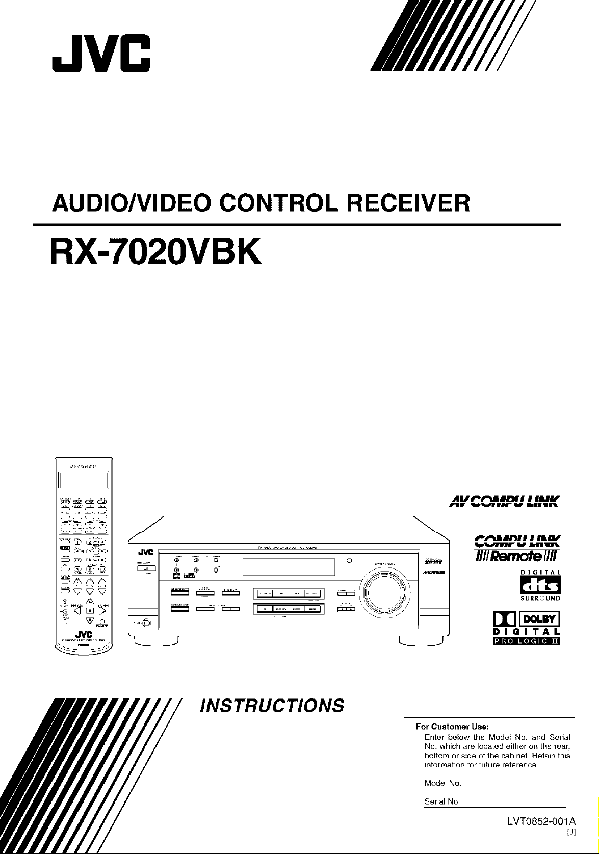
AUDIO/VIDEO CONTROL RECEIVER
RX-7020VBK
AV t'_l_llilJ_l l I IAIiLr
JglIV _]rvlrl_ _IIVJfIL
I_ _0
.J _..
_o©
INSTRUCTIONS
For Customer Use:
P'l_dlll_l I I IW
D]GITAL
SURROUND
DE]_
DIGITAL
_",,Ill;lie]Iq*][q[q Ill
Enter below the Model No. and Serial
No. which are located either on the rear,
bottom or side of the cabinet. Retain this
information for future reference.
Model No.
Serial No.
LVT0852-001 A
[J]
CAUTION: TO REDUCE THE RiSK OF ELECTRIC SHOCK.
REFER SERVICING TO QUALIFIED SERVICE PERSONNEL.
DO NOT REMOVE COVER (OR SACK)
NO USER SERVICEABLE PARTS INSIDE.
For Canada/pour le Canada
CAUTION: TO PREVENT ELECTRIC SHOCK, MATCH WIDE
BLADE OF PLUG TO WIDE SLOT, FULLY INSERT
ATTENTION: POUR EVITER LES DHOCS ELECTRIQUES,
INTRODUIRE LA LAME LA PLUS LARGE DE LA FICHE DANS LA
BORNE CORRESPONDANTE DE LA PRISE ET POUSSER
JUSQUAU FOND
The lightning flash with arrowhead symbol,
within an equilateral triangle is intended to
alert the user to the presence of uninsulated
"dangerous voltage" within the product's
enclosure that may be of sufficient
magnitude to constitute a risk of electric
shock to persons.
The exclamation point within an equilateral
triangle is intended to alert the user to the
presence of important operating and
maintenance (servicing) instructions in the
literature accompanying the appliance.
WARNING: TO REDUCE THE RISK OF FIRE
OR ELECTRIC SHOCK, DO NOT EXPOSE
THIS APPLIANCE TO RAIN OR MOISTURE.
CAUTION
To reduce the risk of electrical shocks, fire, etc.:
1. Do not remove screws, covers or cabinet.
2. Do not expose this appliance to rain or moisture.
ATTENTION
Afin d'eviter tout risque d'electrocution, d'incendie, etc.:
1. Ne pas enlever les vis ni Ies panneaux et ne pas ouvdr le
coffret de I'appareil.
2. Ne pas exposer I'appareil & Ia ptuie ni & I'humidit&
Caution -- STANDBY/ON O/I button!
Disconnect the mains plug to shut the power off completely. The
STANDBY/ON Oil button in any position does not disconnect
the mains line. The power can be remote controlled.
Attention -- Commutateur STANDBY/ON O/I !
D_connecter la fiche de secteur pour couper completement le
courant. Le commutateur STANDBY/ON ©/I ne coupe jamais
completement laligne de secteur, quelle que soit sa position. Le
courant peut 6tre telecommand&
For U.S.A.
This equipment has been tested and found to comply with the limits
for a Class B digital device, pursuant to part 15 of the FCC Rules.
These limits are designed to provide reasonable protection against
harmful interference in a residential installation.
This equipment generates, uses and can radiate radio frequency
energy and, if not installed and used in accordance with the
instructions, may cause harmful interference to radio
communications. However, there is no guarantee that interference
will not occur in a particular installation. If this equipment does cause
harmful interference to radio or television reception, which can be
determined by turning the equipment off and on, the user is
encouraged to try to correct the interference by one or more of the
following measures:
Reorient or relocate the receiving antenna.
Increase the separation between the equipment and receiver.
Connect the equipment into an outlet on a circuit different from that
to which the receiver is connected.
Consult the dealer or an experienced radio/TV technician for help.
Changes or modifications not expressly approved by the
manufacturer for compliance could void the user's authority to
operate the equipment.
For Canada/pour Le Canada
THIS DIGITAL APPARATUS DOES NOT EXCEED THE CLASS
B LIMITS FOR RADIO NOISE EMISSIONS FROM DIGITAL
APPARATUS AS SET OUT IN THE INTERFERENCE-CAUSING
EQUIPMENT STANDARD ENTITLED "DIGITAL APPARATUS,"
ICES-003 OF THE DEPARTMENT OF COMMUNICATIONS.
CET APPAREIL NUMERIQUE RESPECTE LES LIMITES DE
BRUITS RADIOELECTRIQUES APPLICABLES AUX
APPAREILS NUMERIQUES DE CLASSE B PRESCRITES
DANS LA NORME SUR LE MATERIEL BROUILLEUR;
"APPAREILS NUMERIQUES", NMB-003 EDICTEE PAR LE
MINISTRE DES COMMUNICATIONS.
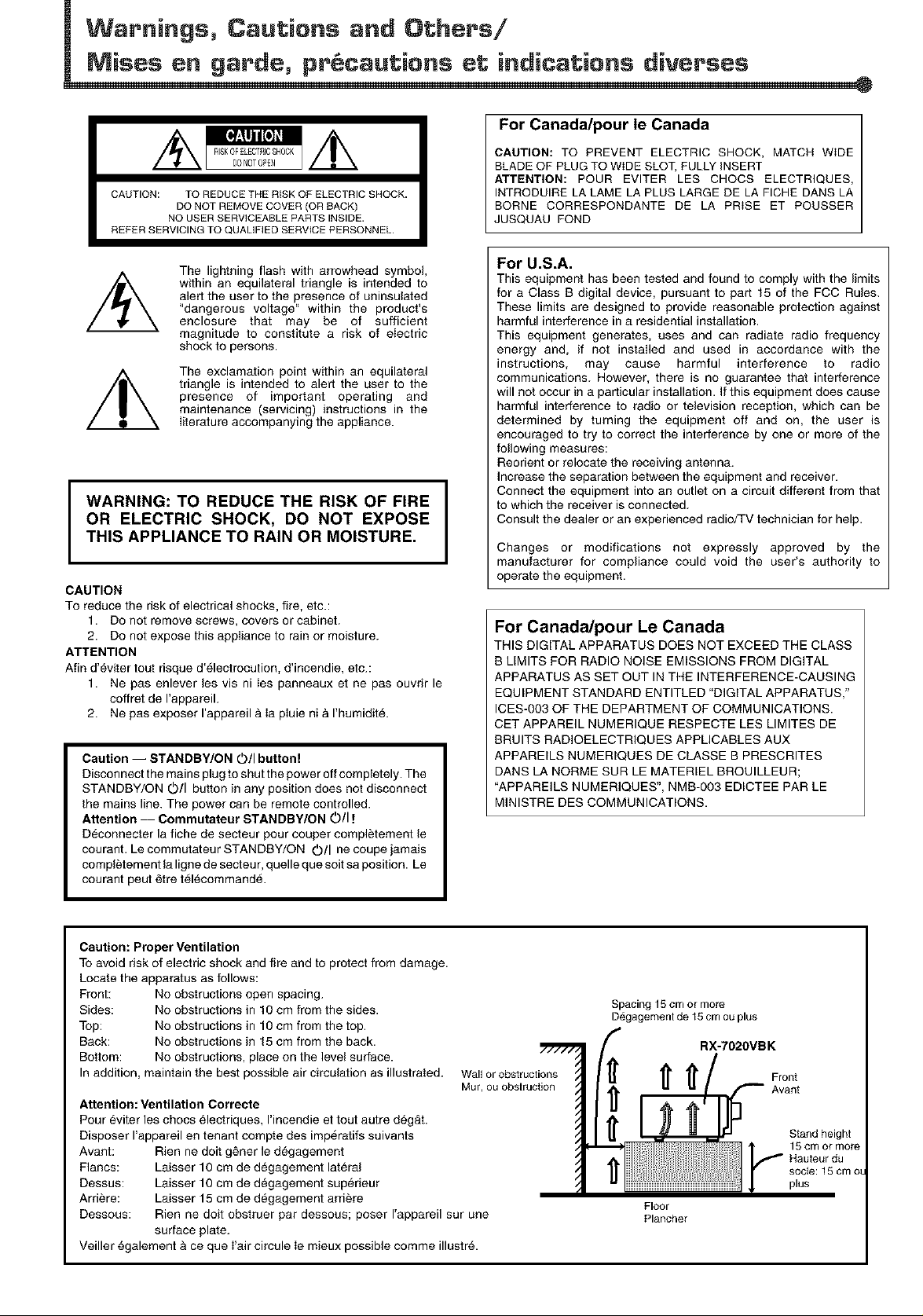
Caution: Proper Ventilation
To avoid risk of electric shock and fire and to protect from damage.
Locate the apparatus as follows:
Front: No obstructions open spacing.
Sides: No obstructions in 10 cm from the sides.
Top: No obstructions in 10 cm from the top.
Back: No obstructions in 15 cm from the back.
Bottom: No obstructions, place on the level surface.
In addition, maintain the best possible air circulation as illustrated. Wall or obstructions
Nut, ou obslruction
Attention: Ventilation Correcte
Pour _viter les chocs electriques, I'incendie et tout autre d_g&t.
Disposer I'appareil en tenant compte des imperatifs suivants
Avant: Rien ne dolt g6ner le degagement
Flancs: Laisser 10 cm de degagement lateral
Dessus: Laisser 10 cm de degagement superieur
Arriere: Laisser 15 cm de degagement arriere
Dessous: Rien ne doit obstruer par dessous; poser rappareil sur une
surface plate.
Veiller egalement & ce que I'air circule Ie mieux possible comme illustr&
Spacing 15 cm or more
Degagemenl de t 5 cm ou plus
RX-7020VBK
Floor
Plancher
Front
Avant
Stand height
Hauteur du
socle: 15 cm OL
y 5 cm or more
plus
Parts Identification ...................................... 2
Getting Started ........................................... 3
Before lnatalla/ion ...................................................................... 3
Checking the Supplied Accessories ........................................... 3
Putting Batteries in the Remole Control .................................... 3
Connecting the FM and AM Anlennas ....................................... 4
Connecting the Speakers ............................................................ 5
Connecting Audio/Video Components ....................................... 6
Connecting the Power Cord ....................................................... 9
Basic Operations ....................................... 10
'Iuming On the Power .............................................................. 10
Selecting the Source to Play ..................................................... I0
Adjusting the Volume ............................................................... 11
Selecting the Front Speakers .................................................... 11
Lislening Only with Headphones ............................................. 12
'Iuming Off the Sounds Temporarily Muting ........................ 12
Changing the Display Brightness ............................................. 12
'Iuming Off the Power with the Sleep Timer ........................... 12
Basic Settings ........................................... 14
Selling the Digital Input (DIGrIAL IN) Terminals ................. 14
Selecting the Analog or Digital Input Mode ............................ 15
Selecting the Video Input Terminal .......................................... 16
Setting the Speaker lnforma/ion ............................................... 16
Sound Adjustments .................................... 19
Attenuating the Input Signal .................................................... 19
Ac[justing the Front Speakers Output Balance ......................... 19
Adjusting the Tone ................................................................... 20
Adjusting the Subwoofer Output Level .................................... 20
Reinforcing the Bass ................................................................ 20
Tuner Operations ....................................... 21
Tuning in Stations Manually .................................................... 21
Using Preset Tuning ................................................................. 21
Selecting the FM Reception Mode ........................................... 22
Creating Realistic Sound Fields ................... 23
About Relations between Speaker Layouts and
Surround Modes ................................................................. 25
Using Dolby Pro Logic 1i, Dolby Digital
and DTS Digital Surround ................................................. 26
Using DAP Modes and All Channel Stereo ............................. 28
Using DVD MULTI Playback Mode ................ 30
Activating DVD MULTI Playback Mode ................................ 30
COMPU LINK Remote Control System ......... 31
AV COMPU LINK Remote Control System .... 32
Operating JVC's Audio/Video
Components .......................................... 34
Operating Audio Components .................................................. 34
Operating Video Components .................................................. 36
Operating Other Manufacturers' Video
Equipment ............................................ 37
Troubleshooting ......................................... 40
Specifications ............................................ 41
m
¢D
o
_ ONLY be used for the operation explained.
[_le] his mark indicates that the remote control CANNOT
'['his mark indicates that the remote control CAN
be used for the operation explained. Use buttons on
the front panel.
1
.IVC
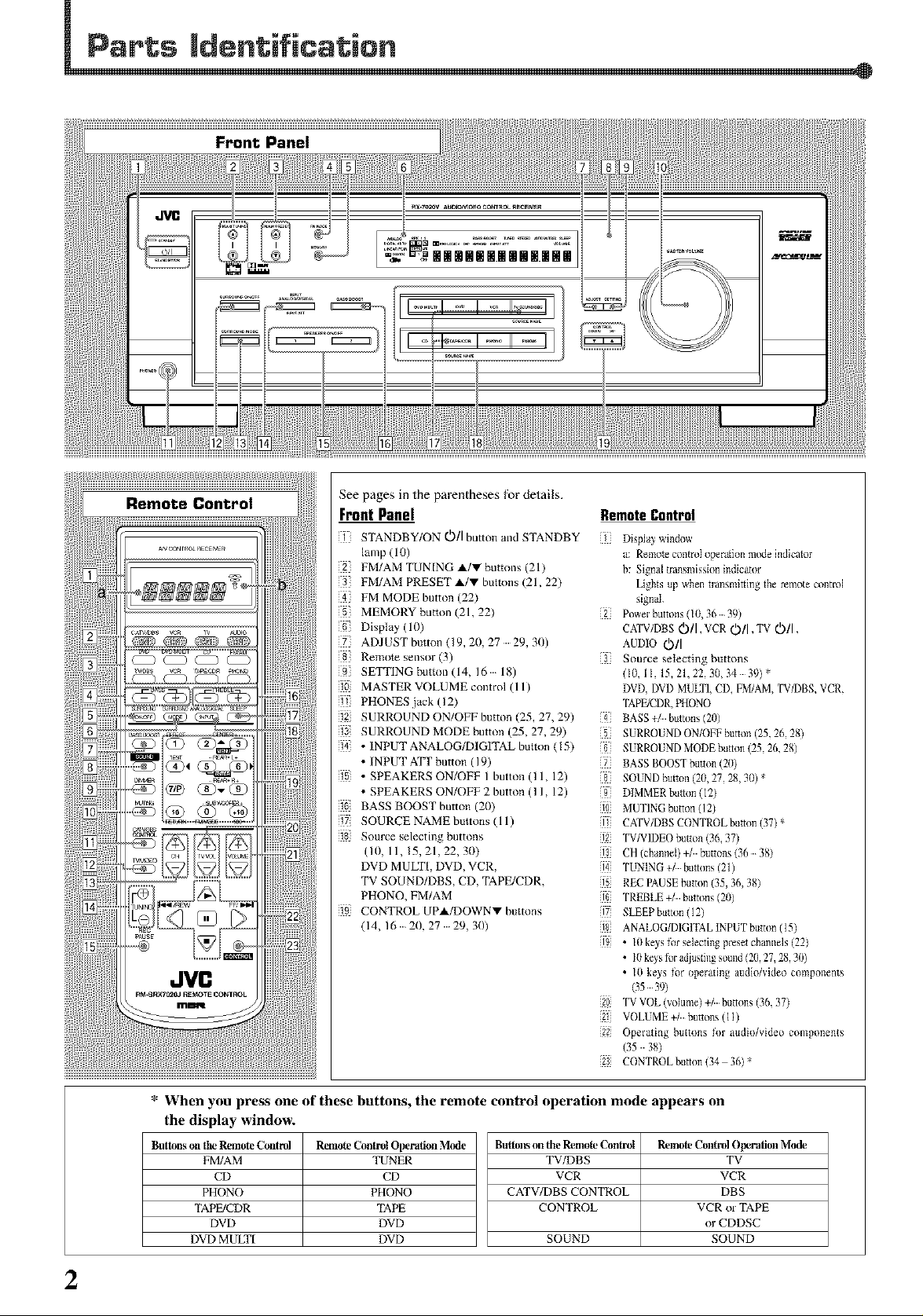
See pages in the parentheses for details.
Front Panel
STANDBY/ON ¢_)/I button and STANDBY
lamp (10)
2 FM/AM TUN [NG A/V buttons (21)
3 FM/AMPRESETA/Vbuttons(21,22)
FM MODE button (227
MEMORY button (21, 22)
Display(l())
• ADJUSTbutton(19,20,27 29,30)
8 Remote sensor (3)
9 SETTING button (14, 16 18)
10 MASTER VOLUME control (11)
11 PHONES .iack (12)
SURROUND ON/OFF button (25, 27, 297
SURROUND MODE button (25, 27, 29)
i4 • INPUT ANALOG/DIGITAL button (157
• INPUT ATT button (19)
i • SPEAKERS ON/OFF I button (I 1, 12)
• SPEAKERS ON/OFF 2 button (I I, 12)
i_ BASS BOOST button (20)
17 SOURCE NAME buttons (11 )
i_ Source selecting buttons
(10, 11, 15, 21,22, 30)
DVD MULTI, DVD, VCR,
TV SOUND/DBS, CD, TAPE/CDR.
PHONO, FM/AM
i_ CONTROL UPA/DOWNV buttons
(14, 16 20. 27 29, 30)
RemoteControl
Display window
a: Remote contmI operation mcule indicator
b: Signal transmission indicator
Lights up whea transmhting the remote control
signal.
Power buttons (10, 36 39)
CATV/DBS Oil ,VCR Oil ,TV OIl,
AUDIO 0/I
Source selecting buttons
(10, 11, 15, 21, 22, 30, 34 39) *
I)VI), DVI) MULTI, CI), PM/AM, TV/DBS, VCR,
"IAPE/CDR, PHONO
BAgS buttons (20)
SURROUND ON/(-)PF button (25, 26, 28)
SURROUND MODE button (25, 26, 28)
BAgS BOOST button (20)
SOUND button (2(/, 27, 28, 30) *
I)IMMER button (12)
0 MUTING button (12)
CATV/DBS CONTROL button (37) *
2 TV/VIDEO button (36, 37)
CH (channel) buttons (36 38)
14 TUNING buttons (21)
REC PAUSE button (35, 36, 38)
TREBLE buttons (20)
SLEEP button (12)
18 ANALOG/I)IGPFAL INPI)T button (15)
• 10 keys B_r selecting preset chanaels (22)
• 10 ke>s fill adjusting somld (20, 27, 28, 30)
• 10 keys lk_r operating audio/video components
(35 39)
20 "IW VOL (volume) buttons (36, 37)
2:j VOLUME buttons (l l)
22 Operating buttons lk)r audio/video components
(35 3g)
23 CONTROL button (34 36) *
* When you press one of these buttons, the remote control operation
mode appears on
the display window.
Buttons on the Remote Control
FM/AM
CD
PHONO
TAPFdCDR
DVD
DVD MULTI SOUND
RemoteControtOperation M_e
TUNER
CD
PHONO
TAPE
DVD
DVD
Bu_.o]t_onthe Remote Control
TV/DBS
VCR
CATV/DBS CONTROL
CONTROL
RemoteC_a_ ()_rafi_nMode
TV
VCR
DBS
VCRorTAPE
orCDDSC
SOUND
2
General Precautions
• DO NOT insert any metal object into the unit.
• DO NOT disassemble the unit or remove screws, covers, or
cabinet.
• DO NOT expose the unit to rain or moisture.
Locations
• Install the unit ill a location that is level and prolected from
moisture.
• The temperature around the unit must be between 5°C and 35_'C
(23°F and 95°F).
• Make sure there is good ventilalion around the unit. Poor
ventilation could cause overhea/ing and damage the unit.
Handling the unit
• DO NOT touch the power coM with wet hands.
DO NOT pull on the power cord to unplug the cord. When
unplugging the cord, always grasp the plug so as not to damage
the cord.
Keep the power cord away from the connecting cords and the
antenna. 'lhe power cord may cause noise or screen interference. It
is recommended to use a coaxial cable for antenna connection,
since it is well-shielded against interference.
• When a power failure occurs, or when you unplug the power cord,
the preset settings such as preset FM/AM channels and sound
ac/justments may be erased in a few days.
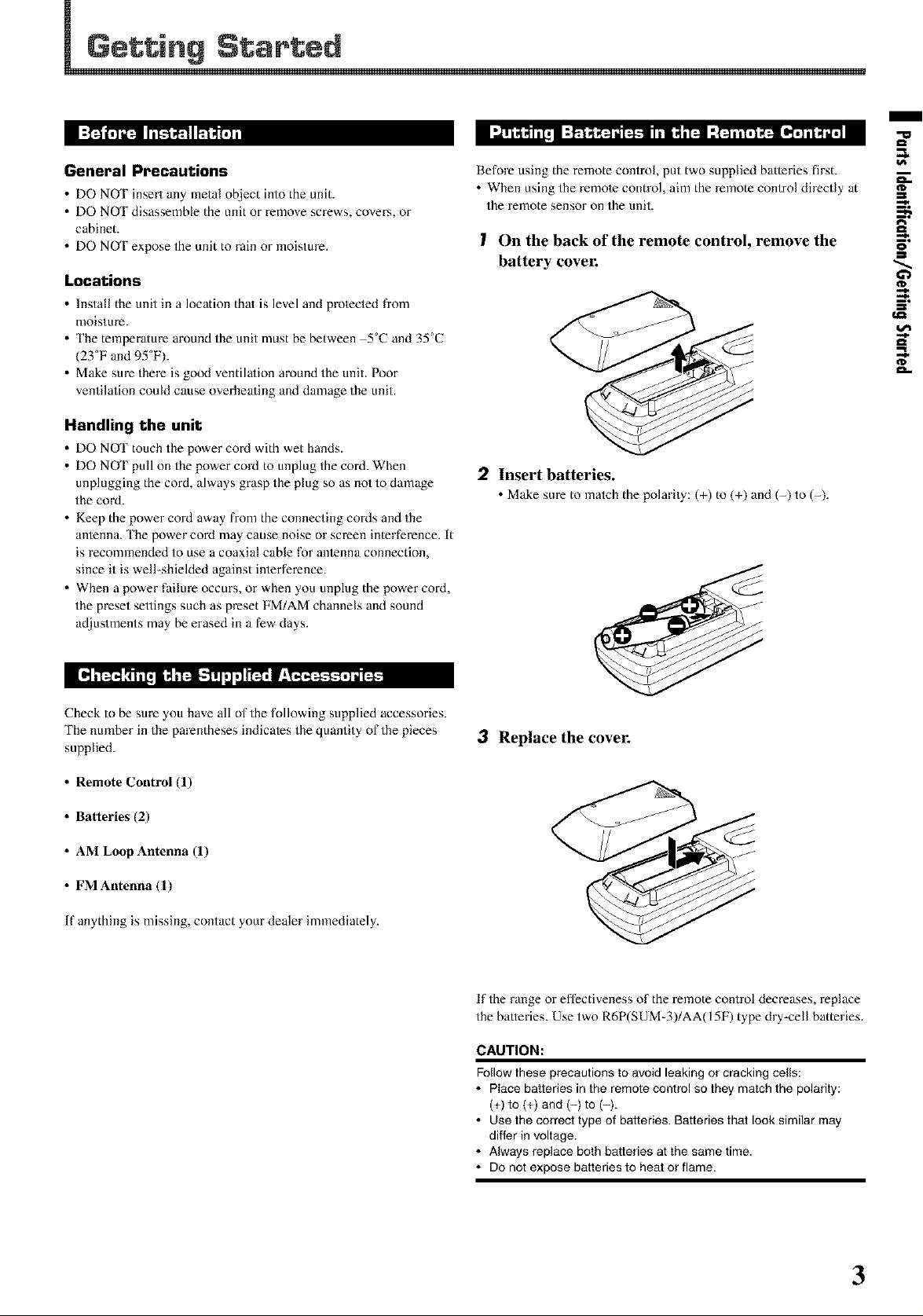
Before using the remote control, put two supplied batteries first.
• When using the remote control, aim the remote control directly at
the remote sensor on the unit.
I On the back of the remote control, remove the
battery cover.
2 Insert batteries.
• Make sure to match the polarity: (+) to (+) and (-) to (-).
/
"u
t_
m
_--%
O
_--%
Check to be sure you have all of the following supplied accessories.
The number in the parentheses indicates the quantity of the pieces
supplied.
• Remote Control (l)
• Batteries (2)
• AM Loop Antenna (l)
• FM Antenna (1)
If anything is missing, contact your dealer immediately.
3 Replace the cover.
%
If the range or effectiveness of the remote control decreases, replace
the batteries. Use two R6P(SUM-3)/AA(15F) type dry-cell batteries.
CAUTION:
Follow these precautions to avoid leaking or cracking cells:
• Place batteries in the remote control so they match the polarity:
(+) to (+) and (-) to (-).
• Use the correct type of batteries. Batteries that look similar may
differ in voltage.
• Always replace both batteries at the same time.
• Do not expose batteries to heat or flame.
3
Getting Started
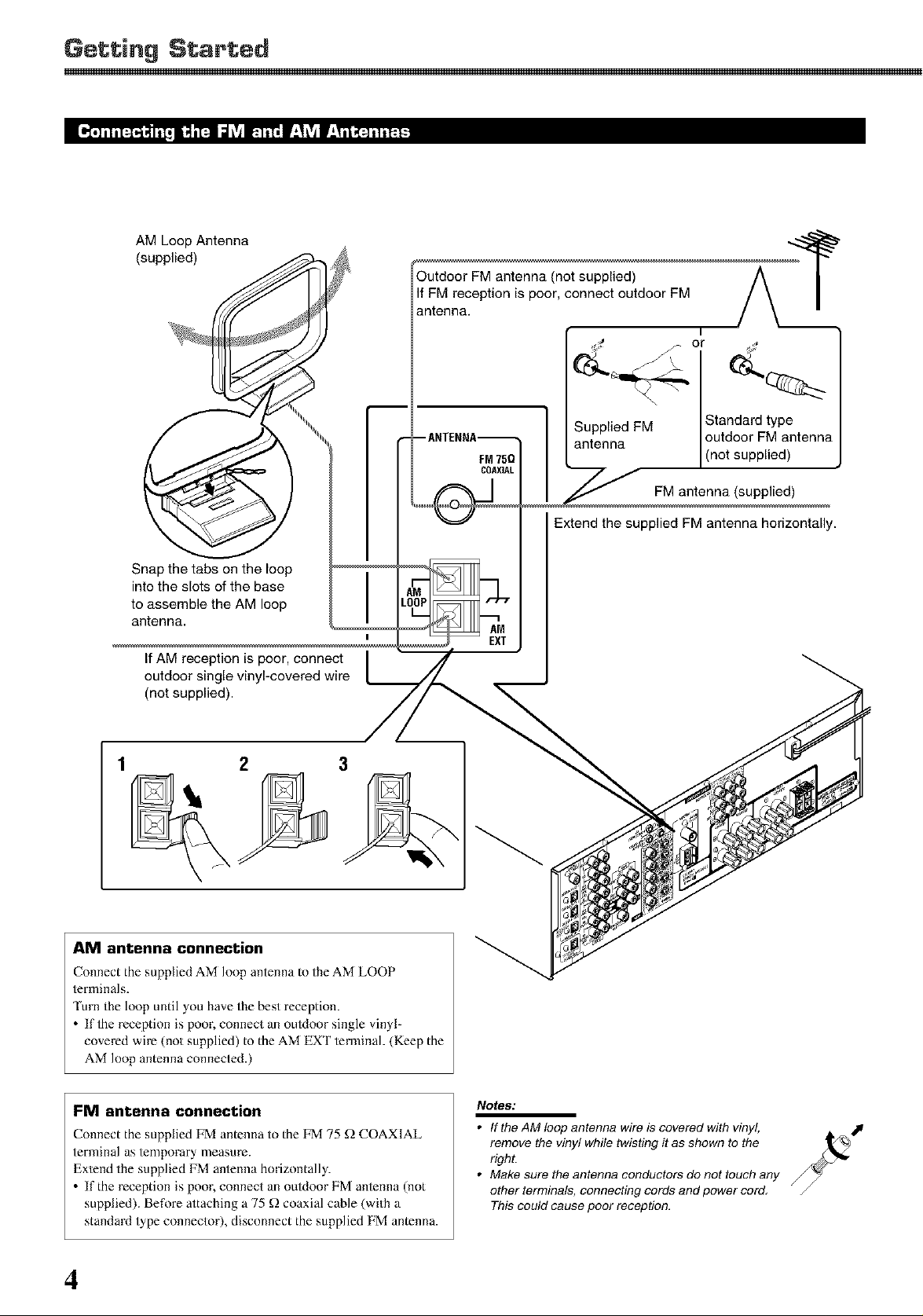
AM Loop Antenna
(supplied)
(not supplied)
reception is poor, connect outdoor FM
antenna.
or
Snap the tabs on the loop
into the slots of the base
to assemble the AM loop
antenna.
If AM reception is poor, connect /
outdoor single vinyl-covered wire [__
(not supplied).
3
Supplied FM
antenna
Standard type
outdoor FM antenna
(not supplied)
FM antenna (supplied)
Extend the supplied FM antenna horizontally.
AM antenna connection
Connect the supplied AM loop antenna to the AM LOOP
terminals.
Turn the loop until you have the best reception.
• If the reception is poor, connect an ouldoor single vinyl-
covered wire (not supplied) to the AM EXT terminal. (Keep the
AM loop antenna connected.)
FM antenna connection
Connect the supplied FM antenna to the FM 75 _ COAXIAL
terminal as lemporary measure.
Ex/end the supplied FM antenna horizontally.
• If the reception is poor, connect an ouldoor FM anlenna (not
supplied). Before attaching a 75 _) coaxial cable (with a
standaM lype connector), disconnect the supplied FM antenna.
4
Notes:
• If the AM loop antenna wire is covered with vinyl,
remove the vinyl while twisting it as shown to the
right.
• Make sure the antenna conductors do not touch any
other terminals, connecting cords and power cord.
This could cause poor reception.
for lhe
SMALL for the center and rear speakers are initial settings. To
get best possible sound, change the subwoofer and speaker settings
I',NO" subwoofer, "LARGE" for the front speakers, and
to fit your listening conditions.
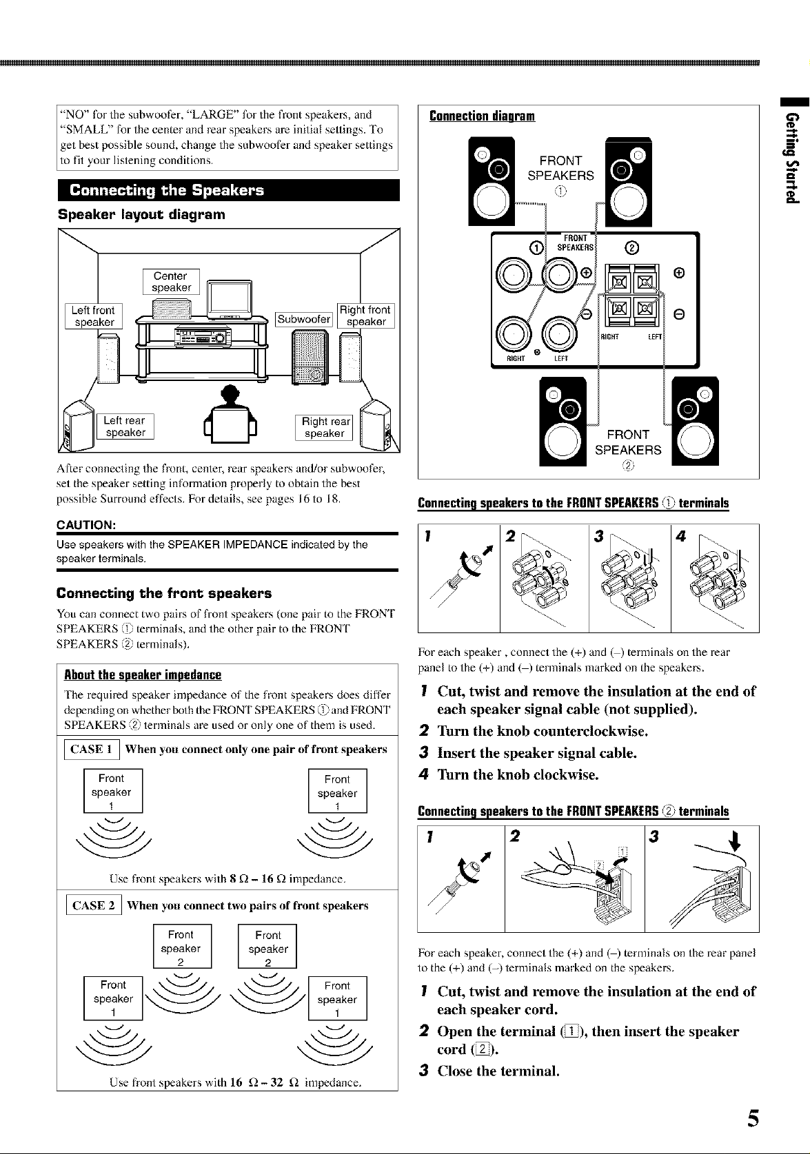
Speaker layout diagram
I Centerspeaker ]
After connecting the fronb center, rear speakers and/or subwoofer,
set the speaker setting information properly to obtain the best
possible Surround effects. For details, see pages 16 to 18.
CAUTION:
Use speakers with the SPEAKER IMPEDANCE indicated by the
speaker terminals.
Connectiondiagram
FRONT
SPEAKERS
FRONT
SPEAKERS
Connectingspeakersto the FRONTSPEAKERS@ terminals
/
II=
Connecting the front speakers
You can connect two pairs of front speakers (one pair to the FRONT
SPEAKERS =1).terminals, and the other pair to the FRONT
, / T
SPEAKERS' / erm nals).
Aboutthespeakerimpedance
'[he required speaker impedance of the front speakers does differ
depending on whe her both he FRONT SPEAKERS _?_,and FRON F
SPEAKERS ,, _=tern nals a'e used or only one of hem s used.
_When you connect only one pair of front speakers
Front
speaker
1
Use front speakers with 8 f_ - 16 f! impedance.
_When you connect two pairs of front speakers
speaker
Front
2
Front
speaker
1
Use front speakers with 16 f!- 32 £_ impedance.
l_breach speaker, connect the (+) and @) terminals on the rear
panel to the (+) and ( ) terminalsmarked on the speakers.
I Cut, twist and remove the insulation at the end of
each speaker signal cable (not supplied).
2 Turn the knob counterclockwise.
3 Insert the speaker signal cable.
4 Turn the knob clockwise.
Connectingspeakersto the FRONTSPEAKERS@ terminals
l_br each speaker, connect the (+) and @) terminals on the rear panel
to the (+) and (-) terminals marked on the speakers.
I Cut, twist and remove the insulation at the end of
each speaker cord.
2 Open the terminal (_1), then insert the speaker
cord (ig).
3 Close the terminal.
5
Getting Started
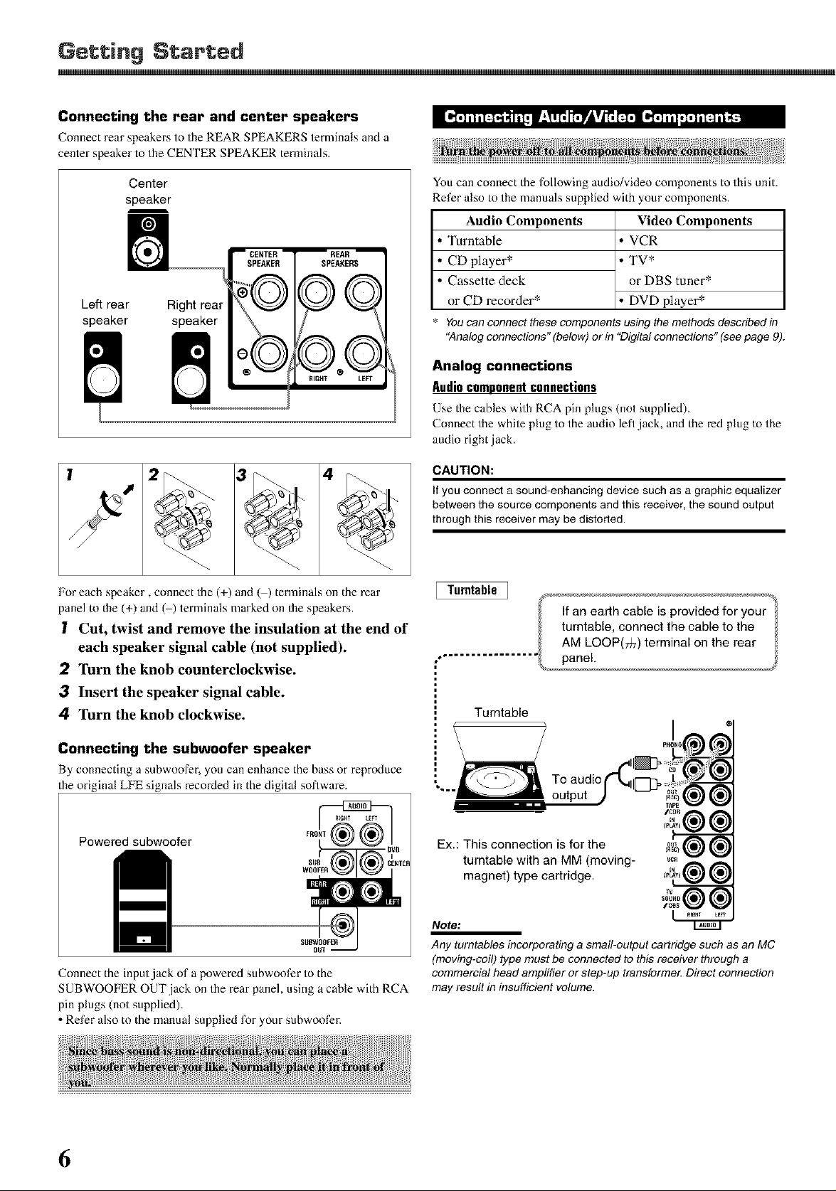
Connecting the rear and center speakers
Connect rear speakersto the REAR SPEAKERS terminals and a
center speaker to the CENTER SPEAKER terminals.
Center
speaker
_CENTER
SPEAKER
REAR
SPEARERS
Left rear Right real
speaker speaker
RIGHT LEFT
F4"4[
You can connect the following audio/video components to this unit.
Refer also to the manuals supplied with your components.
Audio Components
• Turntable
• CD player*
• Cassette deck
or CD recorder*
You can connect these components using the methods described in
"Analog connections" (below) or in "Digital connections" (see page 9).
Analog connections
Audiocomponentconnections
Use the cables with RCA pin plugs (not supplied).
Connect the while plug to the audio left jack, and the red plug to the
audio right .jack.
CAUTION:
If you connect a sound-enhancing device such as a graphic equalizer
between the source components and this receiver, the sound output
through this receiver may be distorted.
Video Components
• VCR
• TV*
or DBS tuner*
• DVD player*
Foreach speaker, connect the (+) and @) terminals on the rear
panel to the (+) and @) terminals marked on the speakers.
I Cut, twist and remove the insulation at the end of
each speaker signal cable (not supplied).
2 Turn the knob counterclockwise.
3 Insert the speaker signal cable.
4 Turn the knob clockwise.
Connecting the subwoofer speaker
By connecting a subwoofer, you can enhance the bass or reproduce
the original LFE signals recorded in the digital software.
Powered subwoofer
Connect the input,jack of a powered subwoofer to the
SUBWOOFER OUT jack on the rear panel, using a cable with RCA
pin plugs (not supplied).
• Refer also to the manual supplied for your subwoofer.
Ex.: This connection is for the
turntable with an MM (moving-
magnet) type cartridge.
Note:
Any turntables incorporating a small-output cartridge such as an MC
(moving-coil) type must be connected to this receiver through a
commercial head amplifier or step-up transformer Direct connection
may result in insufficient volume.
6
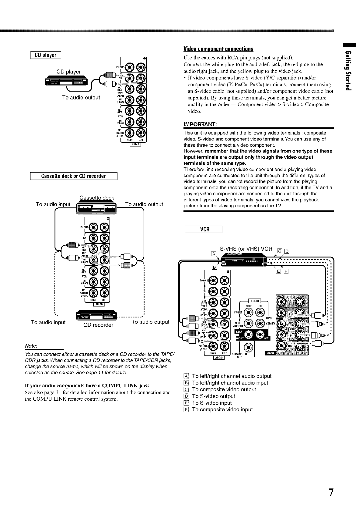
[ CDplayer]
CD player
To audio output
CassettedeckorCDrecorder
Cassette deck
To audio input To audio output
m
Videocomponentconnections
Use the cables with RCA pin plugs (not supplied). _'
Connect the white plug to the audio left jack, the red plug to the S"
audio right jack, and the yellow plug to the video jack.
• If video components have S=video (Y/C=separation) and/or
component vide() (Y, PB/CB, PR/CR) terminals, connect them using _"
an S-video cable (not supplied) and/or component video cable (not
supplied). By using these terminals, you can get a better picture
quality in the order -- Component vide() > S-video > Composite
vide().
IMPORTANT:
This unit is equipped with the following video terminals ; composite
video, S-video and component video terminals. You can use any of
these three to connect a video component.
However, remember that the video signals from one type of these
input terminals are output only through the video output
terminals of the same type.
Therefore, if a recording video component and a playing video
component are connected to the unit through the different types of
video terminals, you cannot record the picture from the playing
component onto the recording component. In addition, ifthe TV and a
playing video component are connected to the unit through the
different types of video terminals, you cannot view the playback
picture from the playing component on the TV.
To audio input CD recorder To audio output
Note:
You can connect either a cassette deck or a CD recorder to the TAPE/
CDR jacks. When connecting a CD recorder to the TAPE/CDR jacks,
change the source name, which wi!l be shown on the display when
selected as the source. See page 11 for details.
If your audio components have a COMPU LINK jack
See also page 31 for detailed information about the connection and
the COMPU LINK remote control system.
VCR
[] S-VHS !orVHS ) VCR _]/[_
IAi To left/right channel audio output
To left/right channel audio input
To composite video output
To S-video output
To S-video input
To composite video input
7
Getting Started
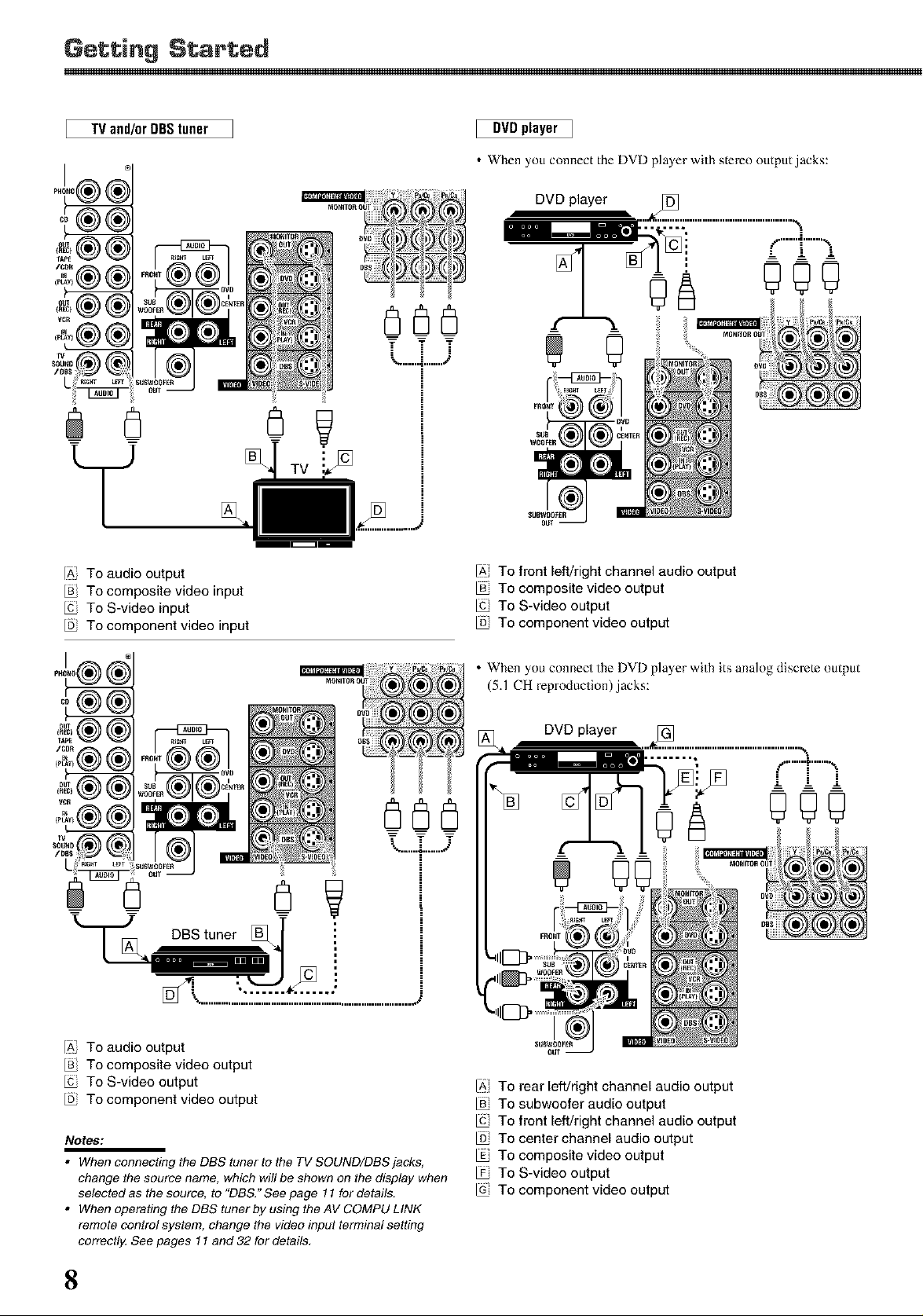
TV and!orDBStuner
IAI To audio output
To composite video input
To S-video input
To component video input
....--, -....-
%,................,_'
DVDplayer 1
• When you connect the DVD player with stereo output,jacks:
DVD player
F""I""'"_
--' J- !
"d
"I" .=ii
IA, TO front left/right channel audio output
To composite video output
To S-video output
To component video output
'= L...L..J
IAI To audio output
To composite video output
To S-video output
To component video output
Notes:
• When connecting the DBS tuner to the TV SOUND/DBS jacks,
change the source name, which will be shown on the display when
selected as the source, to "DBS." See page 11 for details.
• When operating the DBS tuner by using the AV COMPU LINK
remote contro! system, change the video input terminal setting
correctly. See pages 11 and 32 for details,
• When you connect the DVD player with its analog discrete output
(5.1 CH reproduction),jacks:
[AI To rear left/right channel audio output
To subwoofer audio output
To front left/right channel audio output
To center channel audio output
To composite video output
To S-video output
To component video output
8
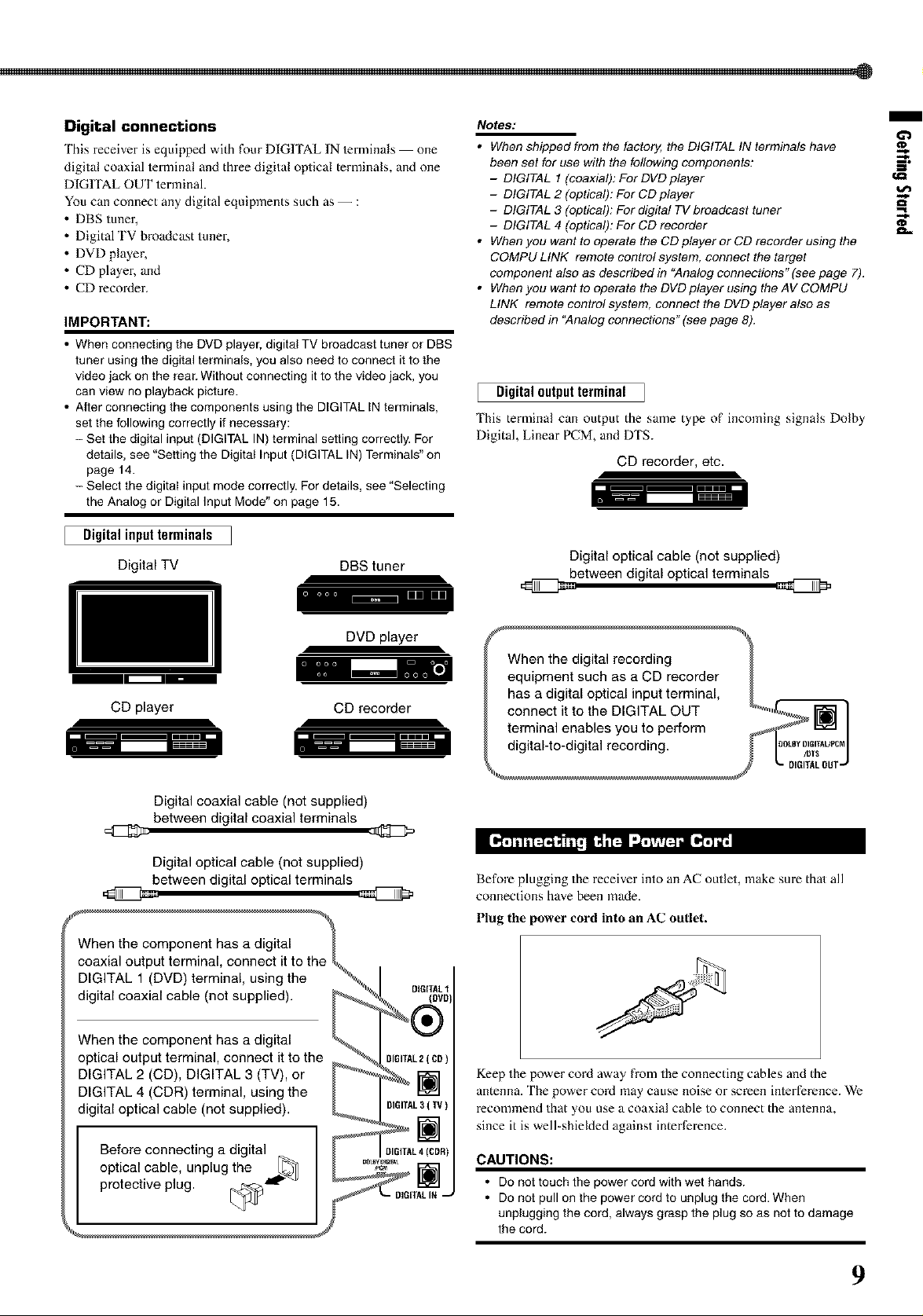
Digital connections
This receiver is equipped with _ur DIGHAL IN terminals one
digital coaxial terminal and three digital optical terminals, and one
DIGITAL OUT terminal.
You can connect any digital equipments such as -- :
• DBS tuner,
• Digital TV broadcast tuner,
• DVD player,
• CD player, and
• CD recoMer.
IMPORTANT:
• When connecting the DVD player, digital TV broadcast tuner or DBS
tuner using the digital terminals, you also need to connect it to the
video jack on the rear. Without connecting it to the video jack, you
can view no playback picture.
• After connecting the components using the DIGITAL IN terminals,
set the following correctly if necessary:
- Sel the digital input (DIGITAL IN) terminal setting correctly. For
details, see "Selting the Digital Input (DIGITAL IN) Terminals" on
page 14.
- Select the digital input mode correctly. For details, see "Selecting
the Analog or Digital Input Mode" on page 15.
Digital input terminals
Digital TV
DBS tuner
NOteS:
• When shipped from the factory, the DIGITAL IN terminals have
been set for use with the fo!lowing components: --_,
- DIGITAL 1 (coaxial): For DVD player
- DIGITAL 2 (optical): For CD player
- DIGITAL 3 (optical): For digital TV broadcast tuner
- DIGITAL 4 (optical): For CD recorder __
• When you want to operate the CD player or CD recorder using the
COMPU LINK remote contro! system, connect the target
component also as described in "Analog connections" (see page 7).
• When you want to operate the DVD player using the AV COMPU
LINK remote contro! system, connect the DVD player also as
described in "Analog connections" (see page 8).
Digitaloutputterminal
'Ihis terminal can output the same type of incoming signals Dolby
Digital, Linear PCM, and DTS.
CD recorder, etc.
Digital optical cable (notsupplied)
between digital optical terminals
/
DVD player
CD player
Digital coaxial cable (not supplied)
between digital coaxial terminals
CD recorder
Digital optical cable (not supplied)
between digital optical terminals
DIGITAL 1 (DVD) terminal, using the % I
digital coaxial cable (not supplied). _ _ DIG[IT_ }
_e_git]_{othe" CL2_C0
p" up " , ' _ _[)lGm ( )
DIGITAL 2 (CD), DIGITAL 3 (TV), or _ _ _
DIGITAL 4 (CDR) terminal, using the _ |
digital optical cable (not supplied). _ [}I61TAL3(W)
I Before connecting a digital I _ _-]
optical cable, unplug the [_ [ L_R)
protect,vep,ug I
Before plugging the receiver into an AC outlet, make sure that all
connections have been made.
Plug the power cord into an AC outlet.
Keep the power coM away from the connecting cables and the
antenna. The power cord may cause noise or screen interference. We
recommend that you use a coaxial cable to connect the antenna,
since it is well-shielded against intertErence.
CAUTIONS:
• Do not touch the power cord with wet hands.
• Do not pull on the power cord to unplug the cord. When
unplugging the cord, always grasp the plug so as not to damage
the cord.
9
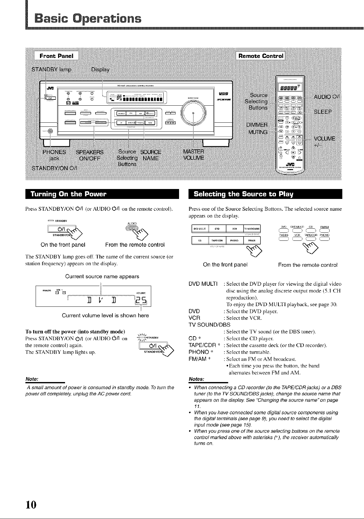
Front Pane|
Press STANDBY/ON O/I (or AUDIO O/I on the remote control).
STANDBY
On the front panel
The STANDBY lamp goes off. The name of the current source (or
station frequency) appears on the display.
Current source name appears
[] [] VOLUME
Current volume level is shown here
To turn oft tile power (into standby mode) ,_
Press STANDBY/ON O/I (or AUDIO O/I on ;_,oB_
the remote control) again. I_Nt_
The STANDBY lamp lights up. s_
Note:
A small amount of power is consumed in standby mode. To turn the
power off completely, unplug the AC power cord.
From the remote control
AUDIO
Press one of the Source Selecting Buttons. The selected source name
appears on the display.
L........ I]
c% c% 4%
%>
On the front panel
DVD MULTI : Select the DVD player for viewing the digital video
disc using the analog discrete output mode (5A CH
reproduction).
To enjoy the DVD MULTI playback, see page 30.
DVD : Select the DVD player.
VCR : Select the VCR.
TV SOUND/DBS
: Select the TV sound (or the DBS tuner).
CD * : Select the CD player.
TAPE/CDR * : Select the cassette deck (or the CD recoMer).
PHONO * : Select the turntable.
FM/AM * : Select an FM or AM broadcast.
• Each time you press the button, the band
alternates between FM and AM.
Notes:
• When connecting a CD recorder (to the TAPE/CDRjacks) or a DBS
tuner (to the TV SOUND/DBS jacks), change the source name that
appears on the display, See "Changing the source name"on page
11.
• Whenyouhaveconnectedsomedigitalsourcecomponentsusing
the digital terminals (see page 9), you need to select the digital
input mode (see page 15).
• Whenyoupressoneofthesourceselectingbuttonsontheremote
contro! marked above with asterisks (_), the receiver automatically
turns OR.
From the remote control
10
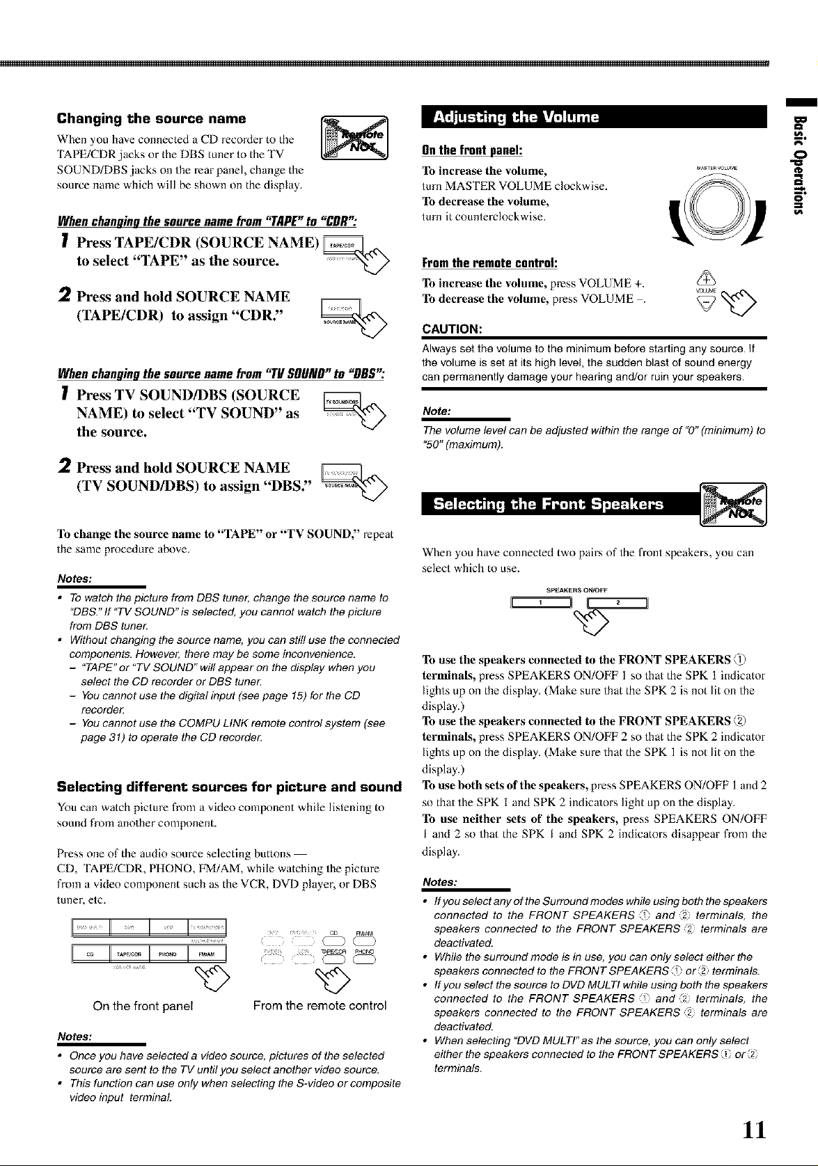
Changing the source name
When you have connected a CD recorder to the
TAPE/CDR jacks oi the DBS tuner to the TV
SOUND/DBS jacks on the rear panel, change the
source name which will be shown on the display.
Whenchanqinqthesourcenamefrom "TAPE"to "DDR":
I Press TAPE/CDR (SOURCE NAME) _,_-x
to select '"IAPE" as the source. _ -'_)
,2 Press and hold SOURCE NAME
(TAPE/CDR) to assign "CDR."
Whenchangingthesourcenamefrom "TUSOUND"to "DBS';"
Press TV SOUND/DBS (SOURCE _^
NAME) to select "TV SOUND" as
the source.
Press and hold SOURCE NAME _^
(TV SOUND/DBS) to assign "DBS."
/
Onthefrontpanel: 0
To increase the volume, ............
To decrease the volume,
turn it counterclockwise.
turn MASTER VOLUME clockwise. L_ ! --_.
Fromtheremotecontrol:
To increase tile volume, press VOLUME +.
To decrease tile volume, press VOLUME . _ _-x)
CAUTION:
Always set the volume _o the minimum before starting any source. If
the volume is set at its high level, the sudden blast of sound energy
can permanently damage your hearing and/or ruin your speakers.
Note:
The volume level can be adjusted within the range of "0" (minimum) to
"50" (maximum).
To change the source name to "TAPE" or "TV SOUND," repeat
the same procedure above.
Notes:
• Towatch the picture from DBS tuner, change the source name to
"DBS." If "TV SOUND" is selected, you cannot watch the picture
from DBS tune_
• Without changing the source name, you can still use the connected
components. However, there may be some inconvenience.
- "TAPE" or "TV SOUND" wi!/appear on the display when you
select the CD recorder or DBS tune_
- You cannot use the digital input (see page 15) for the CD
recorde_
- You cannot use the COMPU LINK remote control system (see
page 31) to operate the CD recorde_
Selecting different sources for picture and sound
You can watch picture fi-om a video component while listening to
sound from another component.
Press one of the audio source selecting buttons
CD, TAPE/CDR, PHONO, FM/AM, while watching the picture
from a video component such as the VCR, DVD player, or DBS
tuner, etc.
I
/
H II II II ]1 ........
On the front panel From the remote control
Notes:
• Once you have selected a video source, pictures of the selected
source are sent to the TV until you select another video source.
• This function can use only when selecting the S-video orcomposite
video input terminal
When you have connected two pairs of the front speakers, you can
select which to use.
SPEAKERS ON/OFF
To use the speakers connected to the FRONT SPEAKERS @
terminals, press SPEAKERS ON/OFF 1 so that the SPK 1 indicator
lights up on the display. (Make sure that the SPK 2 is not lit on the
display.)
To use the speakers connected to the FRONT SPEAKERS @
terminals, press SPEAKERS ON/OFF 2 so that the SPK 2 indicator
lights up on the display. (Make sure that the SPK 1 is not lit on the
display.)
To use both sets of the speakers, press SPEAKERS ON/OFF 1 and 2
so thai the SPK 1 and SPK 2 indica/ors light up on the display.
To use neither sets of the speakers, press SPEAKERS ON/OFF
I and 2 so that the SPK I and SPK 2 indicators disappear from the
display.
Notes:
• IfyouselectanyoftheSurroundmodeswhileusingboththespeakers
connected to the FRONT SPEAKERS "1 and _2 terminals, the
speakers connected to the FRONT SPEAKERS "2 terminals are
deactivated.
• While the surround mode is in use, you can only select either the
speakers connected to the FRONT SPEAKERS "1 or'2 terminals.
• If you select the source to DVD MULTI while using both the speakers
connected to the FRONT SPEAKERS "1 and _2 terminals, the
speakers connected to the FRONT SPEAKERS "2 terminals are
deactivated.
• Whenselecting"DVDMULTl'asthesource, youcanonlyselect
either the speakers connected to the FRONT SPEAKERS i or'2
terminals.
11
Basic OpePations
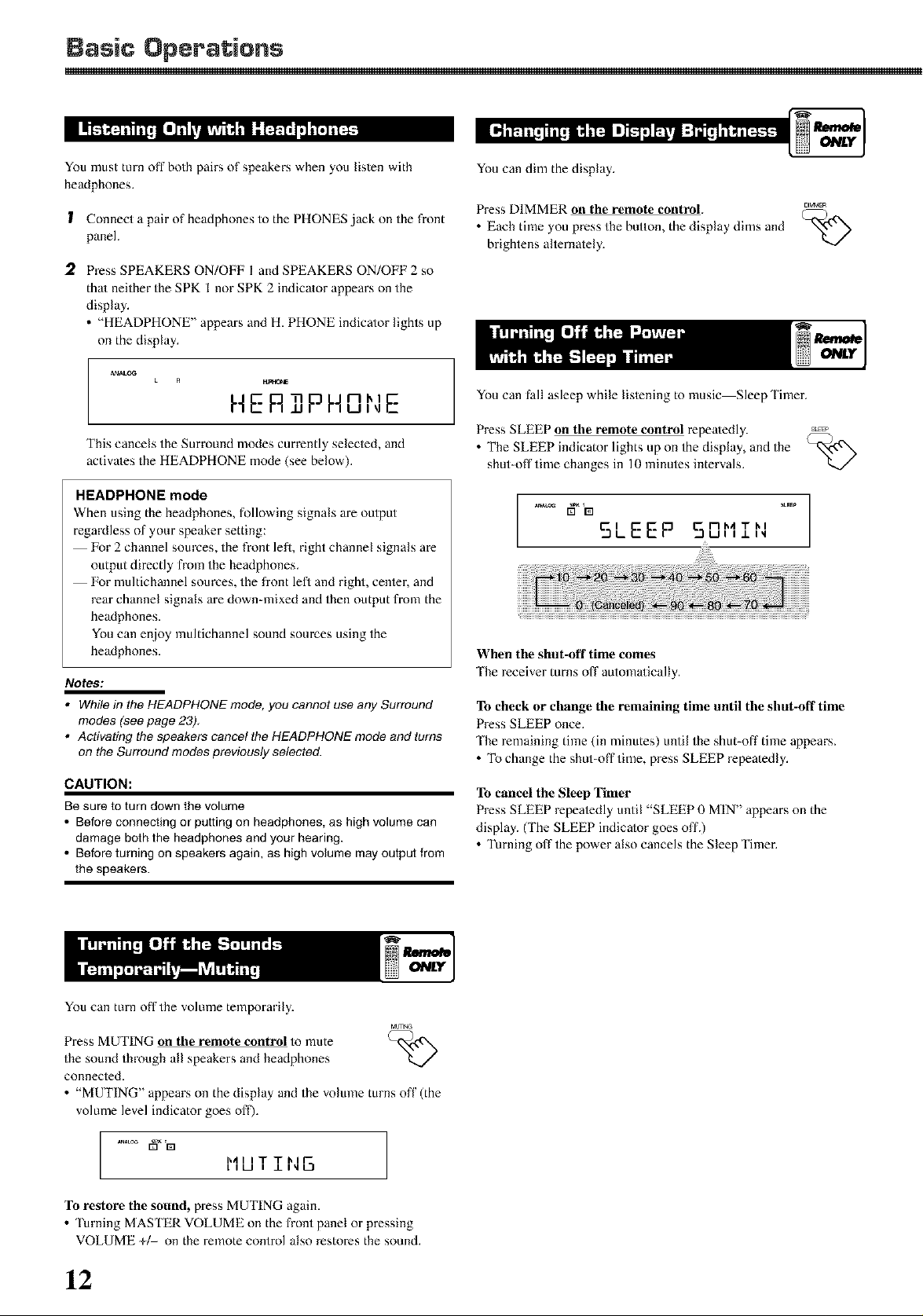
You must turn off both pairs of speakers when you listen with
headphones.
1 Connect a pair of headphones to the PHONES jack on the front
panel.
2 Press SPEAKERS ON/OFF I and SPEAKERS ON/OFF 2 so
thai neither the SPK I nor SPK 2 indicalor appears on the
display.
• "HEADPHONE" appears and H. PHONE indicator lights up
on the display.
A_ALOG
HE RTIPH°NE
This cancels the Surround modes currently selected, and
activates the HEADPHONE mode (see below).
HEADPHONE mode
When using the headphones, following signals are output
regardless of your speaker setting:
For 2 channel sources, the fiont lefi, right channel signals are
output directly fi-om the headphones.
For multichannel sources, the front left and right, cenier, and
)-ear channel signals are down-mixed and then output fiom the
headphones.
You can enjoy multichannel sound sources using the
headphones.
Notes:
• While in the HEADPHONE mode, you cannot use any Surround
modes (see page 23),
• Activating the speakers cancel the HEADPHONE mode and turns
on the Surround modes previously selected.
CAUTION:
Be sure to turn down the volume
• Before connecting or putting on headphones, as high volume can
damage both the headphones and your hearing.
• Before turning on speakers again, as high volume may output from
the speakers.
You can dim the display.
Press DIMMER on the remote colttrol, c_r_R
• Each time you press the button, the display dims and "_-_.N)
brightens alternately.
You can fall asleep while listening to music Sleep Timer.
Press SLEEP on the remote control repeatedly.
• The SLEEP indicator lights up on the display, and the
shut-off time changes in 10 minutes intervals.
When the shut-off time comes
'Ihe receiver turns off automatically.
V../
v.!
To check or change the remaining time until the shut-off time
Press SLEEP once.
'Ihe remaining time (in minutes) until the shut-oil" time appears.
• To change the shut-off'time, press SLEEP repeatedly.
To cancel the Sleep Timer
Press SLEEP repealedly until "SLEEP 0 MIN" appears on the
display. (The SLEEP indicalor goes off.)
• Turning off the power also cancels the Sleep Timer.
You can turn off the volume temporarily.
_TNG
Press MUTING on the remote control to mute
the sound through all speakers and headphones
connected.
• "MUTING" appears on the display and the volume turns off (the
volume level indicator goes off).
ANAL_ _ '[Z]
llkJ J-IM
To restore the sound, press MUTING again.
Turning MASTER VOLUME on the front panel or pressing
VOLUME +/- on the remote control also restores the sound.
-</
12
I
Basicadjustmentauto memory
'Ihis receiver memorizes sound settings for each source when :
• you turn off the power,
• you change the soume, and
• you assign the source name.
When you change the source, the memorized settings for the
newly selected source are automa/ically x-ecalled.
'Ihe following can be stored for each source:
•lnput attenuator mode (see page 19)
• Balance (see page 19)
• Tone ac/justment (see page 20)
• Subwoofer output level (see page 20)
• Surround mode selection (see pages 26 29)
• BASS BOOST (see page 20)
Notes:
l
• Youcannot assign and store different settings for digital input
mode and analog input mode.
• If the source is FM or AM, you can assign a different setting for
each band.
For recording
For analog-to-analog recording
You can record any analog source through the receiver to :
• the cassette deck (or CD recorder) connected to the TAPE/CDR
,jacks, and
• the VCR connected to the VCR,jacks at the same time.
For digital-to-digital recording
You can record the currently selected digital input through the
xeceiver to a digital xecoMing device connected to the DIGITAL
OUT terminal.
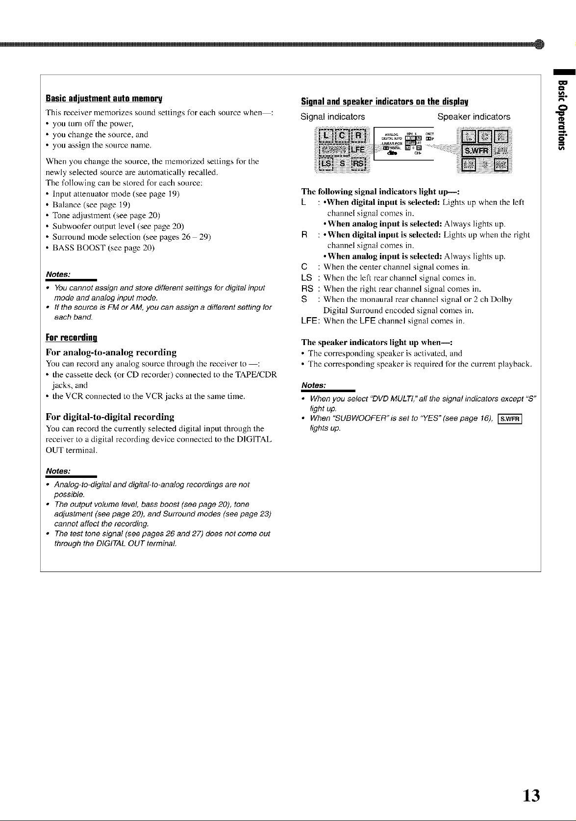
Signal and speaker indicators on the display
Signal indicators Speaker indicators
The following signal indicators light up--:
L : •When digital input is selected: Lights up when the left
channel signal comes ill.
• When analog input is selected: Always lights up.
R : •When digital input is selected: Lights up when the right
channel signal comes ill.
• When analog input is selected: Always lights up.
(3 : When the cenler channel signal comes in.
LS : Whentheleftrearchannelsignalcomesin.
RS : When the right rear channel signal comes in.
S : When the monaural rear channel signal or 2 ch Dolby
Digital Surround encoded signal comes in.
LFE: When the LFE channel signal comes in.
The speaker indicators light up when--:
• The corresponding speaker is activated, and
• The corresponding speaker is required for the current playback.
Notes:
• When you select "DVD MULTI,"all the signal indicators except "S"
light up.
• When 'SUBWOOFER'is set to "YES"(see page 16),
lights up.
0
=%
o
Notes:
l
• Analog-to-digital and digital-to-ana!og recordings are not
possible.
• The output volume level, bass boost (see page 20), tone
adjustment (see page 20), and Surround modes (see page 23)
cannot affect the recording.
• The test tone signal (see pages 26 and 27) does not come out
through the DIGITAL OUT terminal
13
 Loading...