

Page 1
AUDIO/VIDEO CONTROL RECEIVER
RECEPTOR DE CONTROL DE AUDIO/VÍDEO
RECEPTOR DE COMANDO AUDIO/VÍDEO
RX-5000VBK / RX-5001VGD
TA M
MAM
V
V
V M T
UH
P A
M T
8
4
1
- X M T T
TV
V
A
U U
T TA
5
32
T
– T +
5
54
6
5
– A • +
5
98
7
M U
U
– A • +
+ 0
0
-
TV V
+
–
V
+
–
+
+
V
V M
–
–
£
4
1
7
TA
TA
A V T V
/I
V M T V V
AK
2
— O ON
M
TA M
AM
ONE OU H O ERAION
AM
T ATT
A TA T
T
M M
M T
MA T V M
–
INSTRUCTIONS
MANUAL DE INSTRUCCIONES
INSTRUÇÕES
For Customer Use:
Enter below the Model No. and Serial
No. which are located either on the rear,
bottom or side of the cabinet. Retain this
information for future reference.
Model No.
Serial No.
LVT0384-006A
[U, US]
Page 2
Warnings, Cautions and Others / Avisos, precauciones y otras notas /
Advertêcias, precauções e outras notas /
CAUTION
To reduce the risk of electrical shocks, fire, etc.:
1. Do not remove screws, covers or cabinet.
2. Do not expose this appliance to rain or moisture.
PRECAUCIÓN
Para reducir riesgos de choques eléctricos, incendio, etc.:
1. No extraiga los tornillos, los cubiertas ni la caja.
2. No exponga este aparato a la lluvia o a la humedad.
ATENÇÃO
Para reduzir riscos de choques eléctricos, incêndio, etc.:
1. Não retire parafusos nem desmonte as tampas ou o gabinete.
2. Não exponha este aparelho à chuva nem à umidade.
Caution –– switch!
Disconnect the mains plug to shut the power off completely. The
switch in any position does not disconnect the mains line. The power
can be remote controlled.
Precaución –– Interruptor !
Desconectar el cable de alimentación para desactivar la alimentación
totalmente. Cualquier que sea la posición de ajuste del interruptor
, la alimentación no es cortada completamente. La alimentación
puede ser controlada remotamente.
Precaução –– Interruptor !
Desconectar o cabo de alimentação para desligar a alimentação por
completo. Qualquer que seja a posição de ajuste do interruptor ,
a alimentação não é completamente cortada. A alimentação pode
ser controlada remotamente.
G-1
Page 3
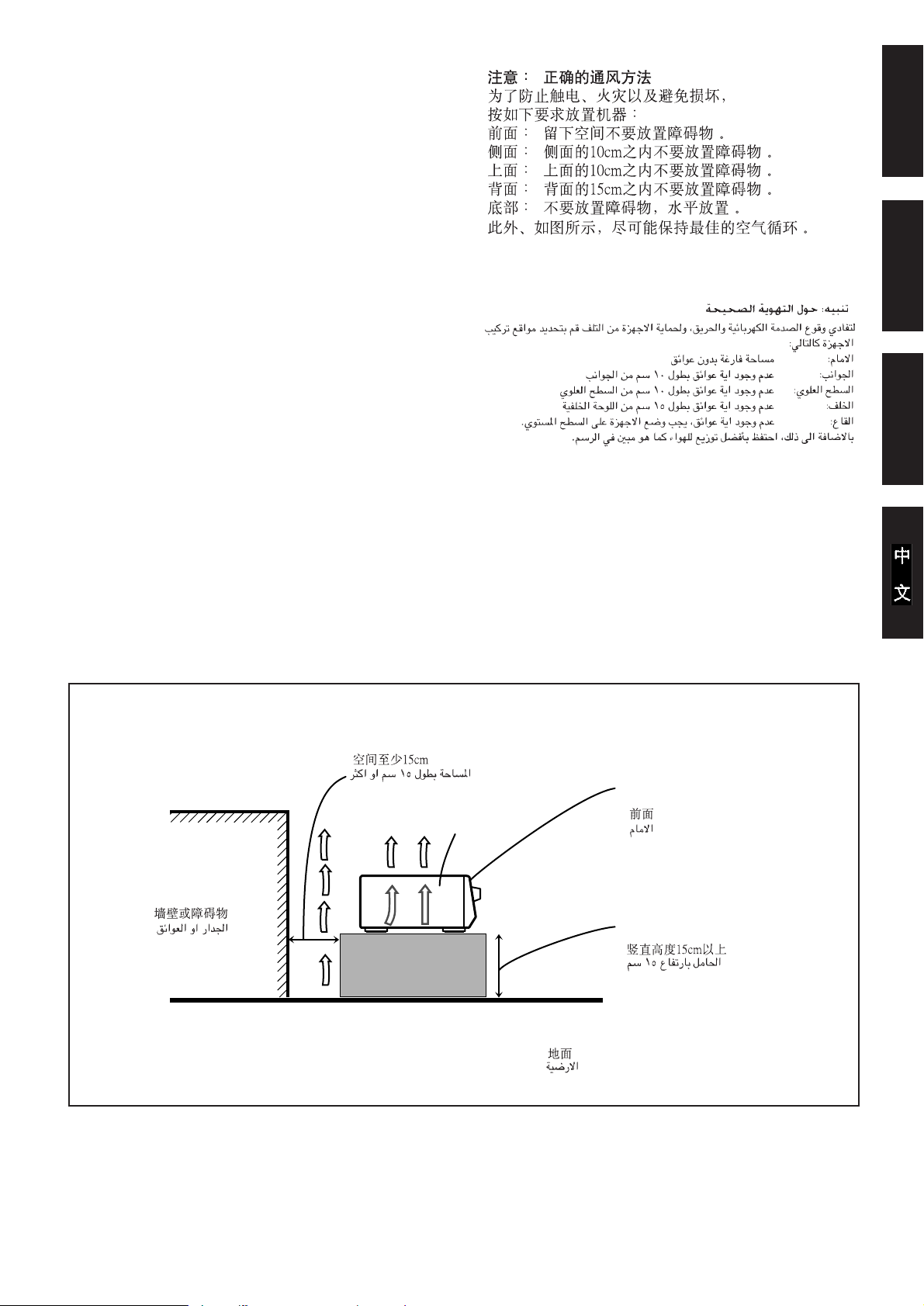
Caution: Proper Ventilation
To avoid risk of electric shock and fire and to protect from damage.
Locate the apparatus as follows:
Front: No obstructions open spacing.
Sides: No obstructions in 10 cm from the sides.
Top: No obstructions in 10 cm from the top.
Back: No obstructions in 15 cm from the back
Bottom: No obstructions, place on the level surface.
In addition, maintain the best possible air circulation as illustrated.
Precaución: Ventilación Adecuada
Para evitar el riesgo de choque eléctrico e incendio y para proteger el
aparato contra daños.
Ubique el aparato de la siguiente manera:
Frente: Espacio abierto sin obstrucciones
Lados: 10 cm sin obstrucciones a los lados
Parte superior: 10 cm sin obstrucciones en la parte superior
Parte trasera: 15 cm sin obstrucciones en la parte trasera
Fondo: Sin obstrucciones, colóquelo sobre una superficie
nivelada
Además, mantenga la mejor circulación de aire posible como se
ilustra.
Precaução: ventilação apropriada
Para prevenir o risco de choque elétrico ou incêndio e para proteger o
aparelho contra danos.
Localize-o da seguinte maneira:
Frente: Espaço aberto, sem obstruções
Lados: Espaço de 10 cm sem obstruções nos lados
Topo: Espaço de 10 cm sem obstruções acima
Atrás: Espaço de 15 cm sem obstruções atrás
Parte inferior: Sem obstruções. Coloque o aparelho em superfície
nivelada.
Mantenha, além disso, a maior circulação de ar possível, como indica
a ilustração.
EnglishPortuguês
Español
Wall or obstructions
Pared u obstrucciones
Parede ou obstáculo
Spacing 15 cm or more
Espacio de 15 cm o más
Espaço de 15 cm ou mais
RX-5000VBK/
RX-5001VGD
Floor
Piso
Piso
Front
Frente
Frente
Stand height 15 cm or more
Allura del soporte 15 cm o más
Base com altura de 15 cm ou mais
G-2
Page 4

English
Table of Contents
Parts Identification...................................... 2
Getting Started........................................... 3
Before Installation ...................................................................... 3
Checking the Supplied Accessories ........................................... 3
Connecting the FM and AM Antennas ....................................... 3
Connecting the Speakers ............................................................ 4
Connecting Audio/Video Components....................................... 5
Connecting the Power Cord ....................................................... 7
Putting Batteries in the Remote Control .................................... 7
Basic Operations ......................................... 8
Turning the Power On and Off (Standby) .................................. 8
Selecting the Source to Play....................................................... 8
Adjusting the Volume................................................................. 9
Selecting the Front Speakers ...................................................... 9
Muting the Sound ....................................................................... 9
Recording a Source .................................................................... 9
Attenuating the Input Signal .................................................... 10
Adjusting the Front Speaker Output Balance........................... 10
Reinforcing the Bass ................................................................ 10
Adjusting the Tone ................................................................... 10
Basic Settings........................................... 11
Changing the Source Name...................................................... 11
Setting Center and Rear Speakers for the DSP Modes ............ 11
Storing the Basic Settings and Adjustments — One Touch
Operation ........................................................................... 12
Using the Sleep Timer.............................................................. 12
Receiving Radio Broadcasts ........................ 13
Setting the AM Tuner Internal Spacing.................................... 13
Tuning in Stations Manually .................................................... 13
Using Preset Tuning ................................................................. 13
Selecting the FM Reception Mode........................................... 14
Using the DSP Modes ................................ 15
Available DSP Modes According to the Speaker Arrangement .. 16
Adjusting the 3D-PHONIC Modes .......................................... 17
Adjusting the DAP Modes ....................................................... 17
Adjusting the Surround Modes — Dolby Surround and JVC
Theater Surround ............................................................... 18
Activating the DSP Modes ....................................................... 19
Using the DVD MULTI Playback Mode.......... 20
Activating the DVD MULTI Playback Mode .......................... 20
1
COMPU LINK Remote Control System ......... 21
Operating JVC’s Audio/Video Components ... 22
Troubleshooting......................................... 24
Specifications............................................ 25
Page 5
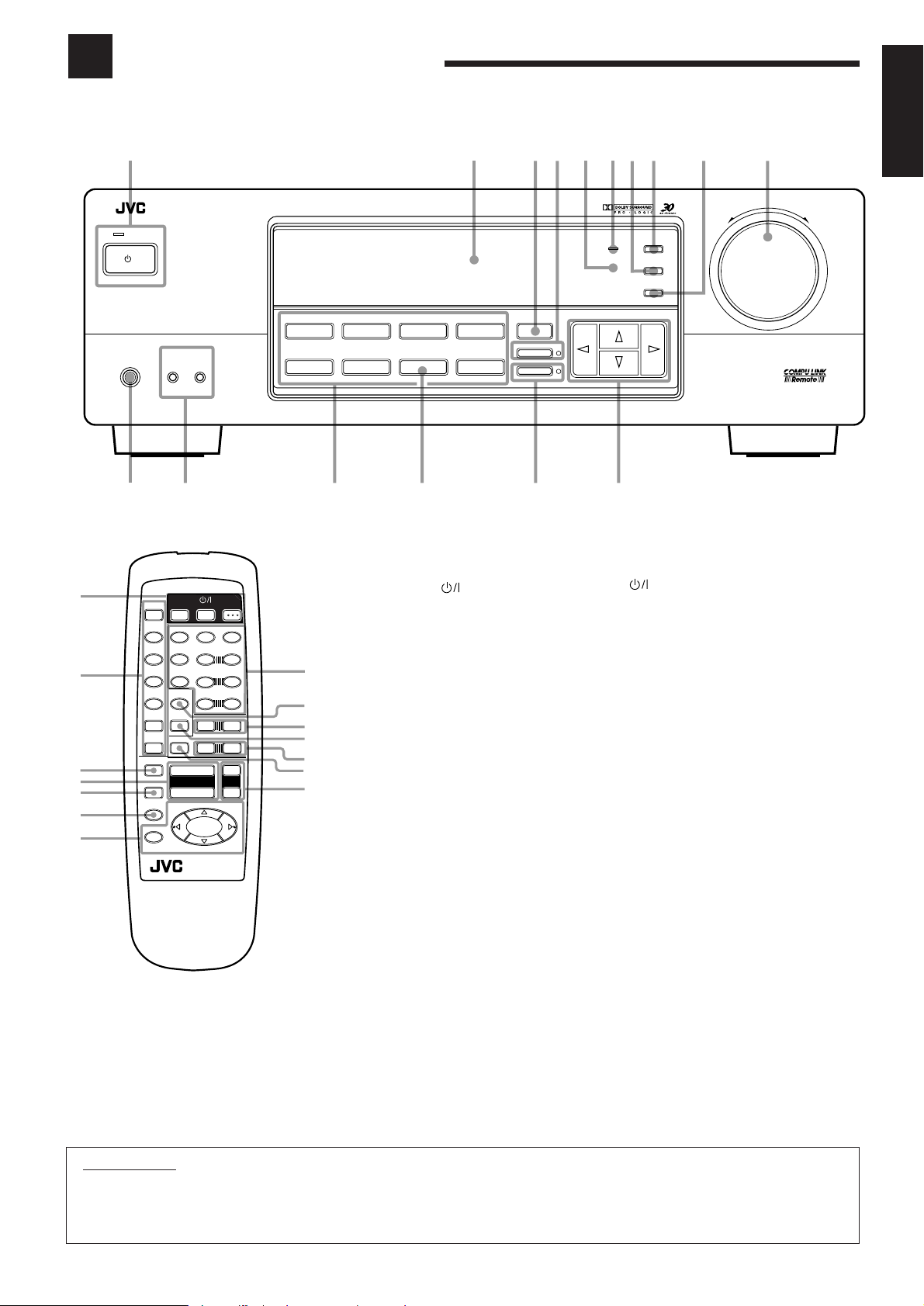
Parts Identification
Become familiar with the buttons and controls on the receiver before use.
Refer to the pages in parentheses for details.
1234869p
AUDIO/VIDEO CONTROL RECEIVER
S ANDB
/I
S ANDB ON
PHONES
SPEAKERS
1
DVD MULTI
2
— OFF_ ON
CD
DVD
PHONO
rty
VCR
TAPE/MD
SOURCE NAME
FM
AM
e
SURROUND
ONE TOUCH OPERATION
INPUT ATT.
w
Front Panel
1
1
2
3
4
5
6
7
V
CD
APE/MD
EFFEC
FM/AM
5
VCR
7/P
DVD
T
DVD MUL I
CD DISC
PHONO
TV/VIDEO
T
AT
+
VOLUME
MU NG
–
SLEEP
8
4
1
RM SR558XU REMO E CON ROL
VCR
ESDELAY
5
CEN ER
54
REAR L
5
REAR R
10
–
–
£
7
V VOL
AUDIO
321
6
5
98
M
+10
T
+
V CH
+
+
VCR CH
–
4
1
8
9
p
q
w
e
r
STANDBY/ON button and STANDBY
lamp (8)
2
Display (8)
3
SURROUND button (16)
4
ONE TOUCH OPERATION button and lamp
(12)
5
Remote sensor (7)
6
BASS BOOST lamp (10)
7
SETTING button (11)*
8
ADJUST button (10)*
9
MEMORY button (13)
p
MASTER VOLUME control (9)
q
Cursor control buttons
w
INPUT ATT. button and lamp (10)
e
SOURCE NAME button (11)
r
Source selecting buttons (8)
DVD MULTI, DVD, VCR, FM*, AM*,
TAPE/MD, PHONO, CD
t
SPEAKERS 1/2 buttons (9)
y
PHONES jack (9)
5
7
ADJUST
BASS BOOST
SETTING
MEMORY
MULTI CURSOR
q
Remote Control
1
2
3
4
5
6
7 •
8 •
9
p
q
w
e
r
buttons (8, 23)
TV, VCR, A UDIO
Source selecting buttons (8)
CD, TAPE/MD, FM/AM, VCR, DVD,
DVD MULTI, PHONO
ONE TOUCH OPERATION button (12)
VOLUME +/– buttons (9)
MUTING button (9)
SLEEP button (12)
Operating buttons for audio/video components
(22)
10 keys for selecting preset channel (14, 22)
•
10 keys for adjusting sound (12, 17, 22)
•
10 keys for operating audio/video components
(22)
SOUND CONTROL button (12, 17, 22)
TV VOL. –/+ buttons (23)
CD-DISC button (22)
TV CH –/+ buttons (23)
TV/VIDEO button (23)
VCR CH +/– buttons (23)
MASTER VOLUME
–+
English
IMPORTANT:
To use the Cursor control buttons (q) on the front panel:
What these buttons actually do depends on which function you are trying to adjust. Before using these buttons, select the function by
pressing one of the buttons marked with *.
2
Page 6
Getting Started
This section explains how to connect audio/video components and speakers to the receiver, and how to connect the
power supply.
English
Before Installation
General
• Be sure your hands are dry.
• Turn the power off to all components.
• Read the manuals supplied with the components you are going to
connect.
Locations
• Install the receiver in a location that is level and protected from
moisture.
• The temperature around the receiver must be between –5°C and
35°C (23°F and 95°F).
• Make sure there is good ventilation around the receiver. Poor
ventilation could cause overheating and damage the receiver.
Handling the receiver
• Do not insert any metal object into the receiver.
• Do not disassemble the receiver or remove screws, covers, or
cabinet.
• Do not expose the receiver to rain or moisture.
Checking the Supplied Accessories
Check to be sure you have all of the following items, which are
supplied with the receiver.
The number in the parentheses indicates quantity of the pieces
supplied.
• Remote Control (1)
• Batteries (2)
• AM Loop Antenna (1)
• FM Antenna (1)
If anything is missing, contact your dealer immediately.
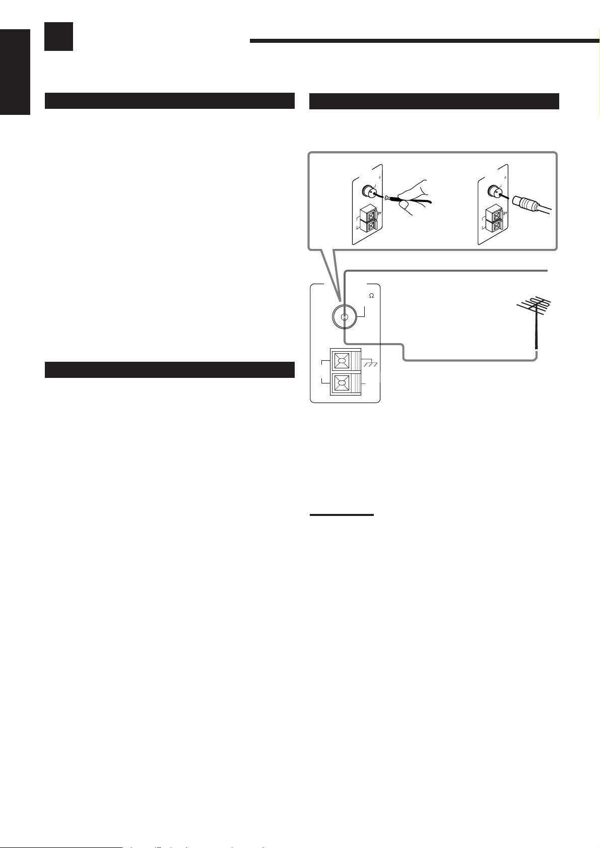
Connecting the FM and AM Antennas
FM Antenna Connections
A
ANTENNA
AM
LOOP
A. Using the Supplied FM Antenna
The FM antenna provided can be connected to the FM 75Ω
COAXIAL terminal as temporary measure.
B. Using the Standard Type Connector (Not Supplied)
A standard type connector should be connected to the FM 75Ω
COAXIAL terminal.
Note:
If reception is poor, connect the outside antenna.
Before attaching a 75Ωcoaxial cable (the kind with a round wire
going to an outside antenna), disconnect the supplied FM antenna.
ANTENNA
AM
LOOP
FM 75
COAXIAL
AM
EXT
AM
LOOP
ANTENNA
FM 75
COAXIAL
AM
EXT
FM 75
COAXIAL
B
AM
EXT
FM Antenna
Extend the supplied FM antenna horizontally.
Outside FM Antenna Cable
3
Page 7
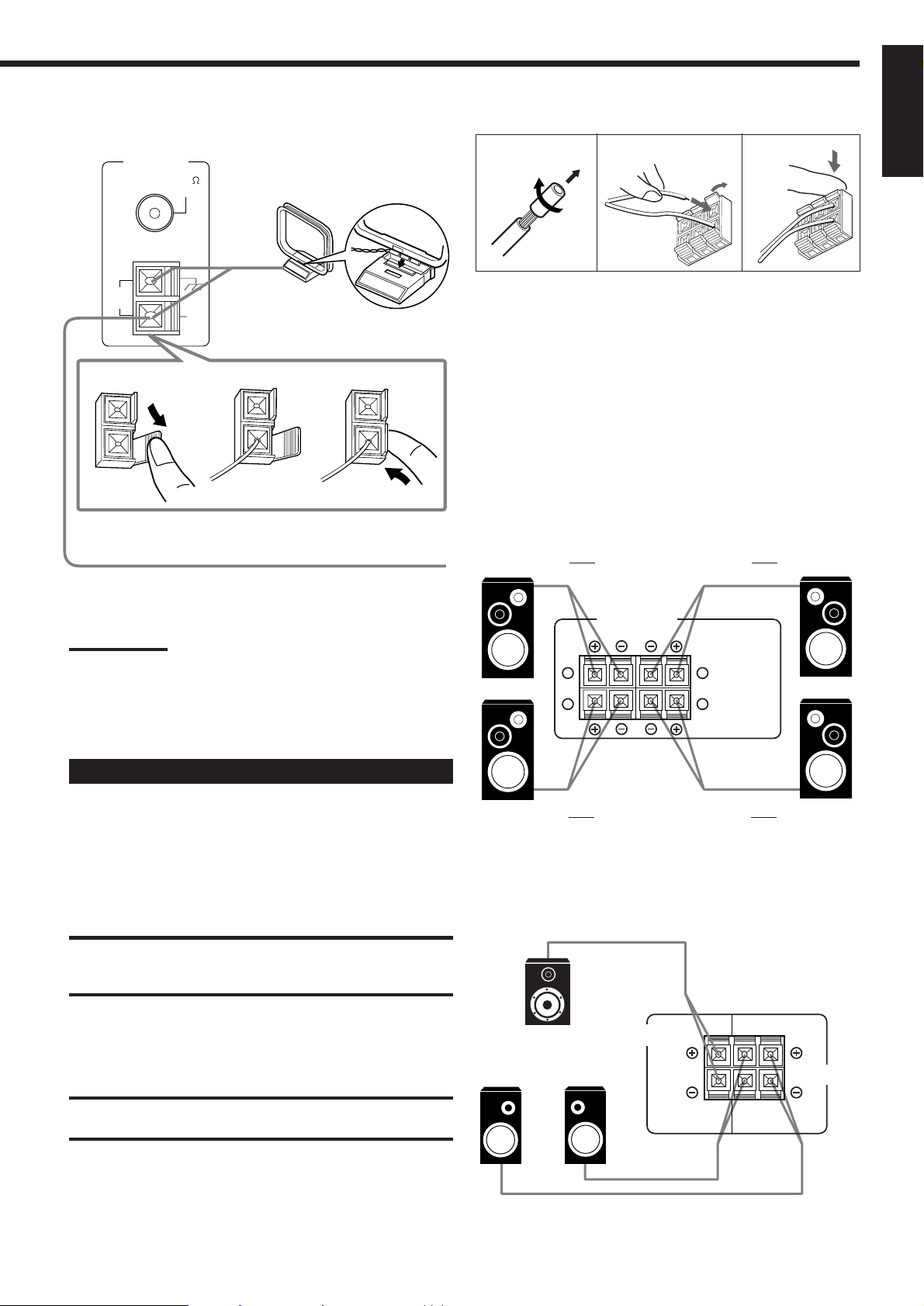
AM Antenna Connections
RIGHT LEFT
FRONT SPEAKERS
1
2
1
2
ANTENNA
FM 75
COAXIAL
Snap the tabs on the loop into the
slots of the base to assemble the
AM loop.
Basic connecting procedure
1
2
3
English
AM
LOOP
1
AM
EXT
AM Loop Antenna
2
3
Outdoor single vinyl-covered wire
Turn the loop until you have the best reception.
Notes:
• Make sure the antenna conductors do not touch any other
terminals, connecting cords and power cord. This could cause poor
reception.
• If reception is poor, connect an outdoor single vinyl-covered wire to
the AM EXT terminal. (Keep the AM loop antenna connected.)
1 Cut, twist and remove the insulation at the end of
each speaker signal cable.
2 Open the terminal and then insert the speaker
signal cable.
3 Close the terminal.
Connecting the front speakers
You can connect two pairs of front speakers (one pair to the FRONT
SPEAKERS 1 terminals, and another pair to the FRONT
SPEAKERS 2 terminals).
Right speaker
FRONT SPEAKERS 1
Left speaker
Connecting the Speakers
You can connect the following speakers:
• Two pairs of front speakers to produce normal stereo sound.
• One pair of rear speakers to enjoy the surround effect.
• One center speaker to produce more effective surround effect (to
emphasize human voices).
• One subwoofer to enhance the bass.
IMPORTANT:
After connecting the speakers listed above, set the speaker setting
information properly to obtain the best possible DSP (Digital Signal
Processor ) effect. For details, see page 11.
For each speaker (except for a subwoofer), connect the (–) and (+)
terminals on the rear panel to the (–) and (+) terminals marked on
the speakers. For connecting a subwoofer, see page 5.
CAUTION:
Use speakers with the SPEAKER IMPEDANCE indicated by the
speaker terminals.
Right speaker
FRONT SPEAKERS 2
Left speaker
Connecting the rear and center speakers
Connect rear speakers to the REAR SPEAKERS terminals and a
center speaker to the CENTER SPEAKER terminals.
Center speaker
Left rear
speaker
Right rear
speaker
CENTER
SPEAKER
RIGHT LEFT
SPEAKERS
REAR
4
Page 8
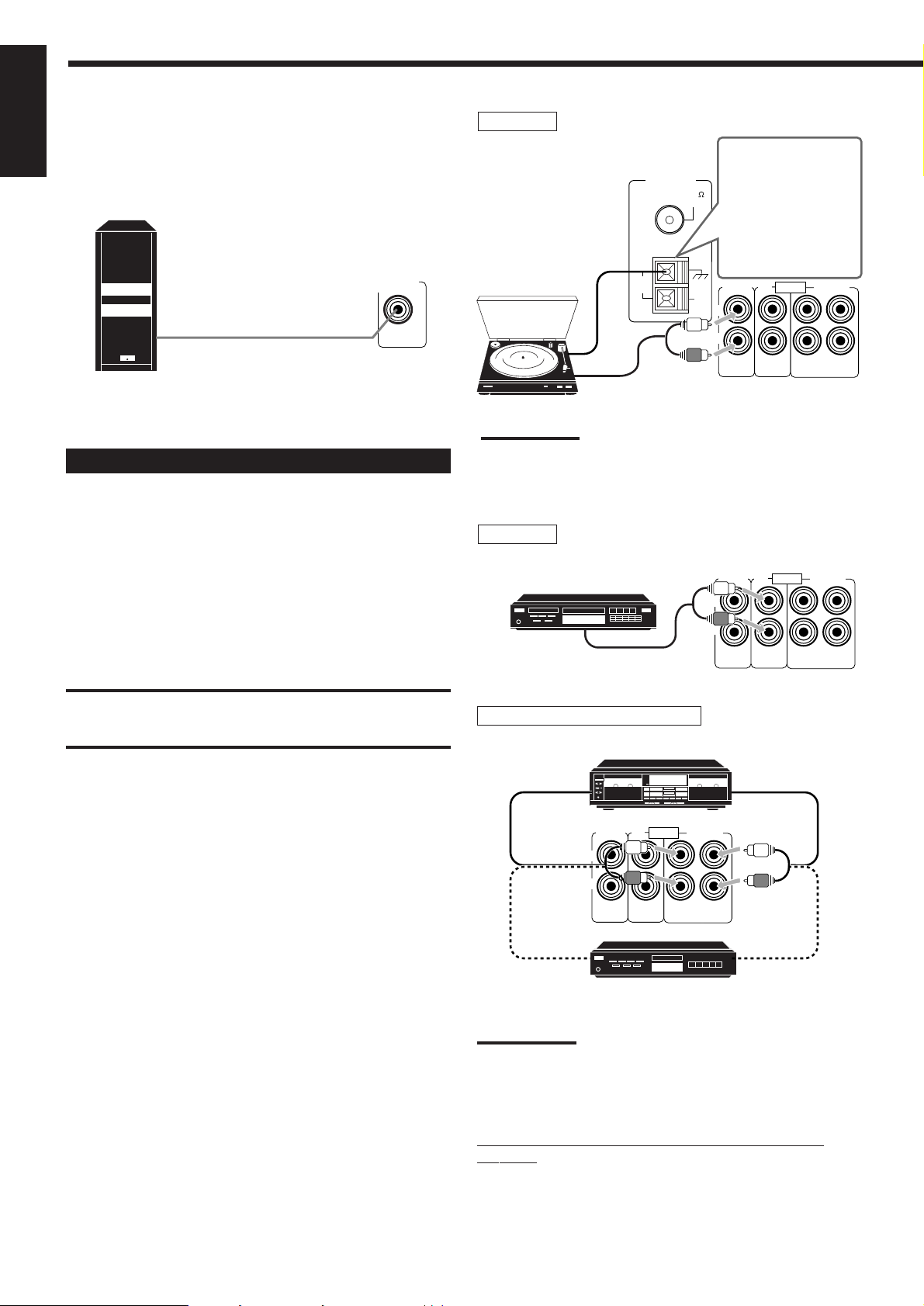
Connecting the subwoofer speaker
AUDIO
PHONO
TAPE/MDCD
OUT
(REC)IN(PLAY)
L
R
You can enhance the bass by connecting a subwoofer.
English
Connect the input jack of a powered subwoofer to the
SUBWOOFER OUT jack on the rear panel, using a cable with RCA
pin plugs.
Powered subwoofer
Connecting Audio/Video Components
You can connect the following audio/video components to this
receiver using cables with RCA pin plugs (not supplied). Refer also
to the manuals supplied with your components.
SUBWOOFER
OUT
Turntable
If an earth cable is
ANTENNA
FM 75
COAXIAL
provided for your
turntable, connect the
cable to the ground
terminal (H) of the
ANTENNA terminals
on the rear panel.
Turntable
AM
LOOP
AM
EXT
PHONO
L
R
AUDIO
OUT
(REC)IN(PLAY)
TAPE/MDCD
To audio output
Note:
Any turntables incorporating a small-output cartridge such as an MC
(moving-coil type) must be connected to this receiver through a
commercial head amplifier or step-up transformer. Direct connection
may result in insufficient volume.
CD player
Use the cables with RCA pin plugs (not supplied).
Connect the white plug to the audio left jack, and the red plug to the
audio right jack.
Audio component connections
CAUTION:
If you connect a sound-enhancing device such as a graphic equalizer
between the source components and this receiver, the sound output
through this receiver may be distorted.
CD player
To audio output
Cassette deck or MD recorder
Cassette deck
To audio input
PHONO
L
R
To audio input
TAPE/MDCD
AUDIO
OUT
(REC)IN(PLAY)
MD recorder
To audio output
To audio output
5
Note:
You can connect either a cassette deck or an MD recorder to the
TAPE/MD jacks. When connecting an MD recorder to the TAPE/MD
jacks, change the source name, which will be shown on the display
when selected as the source, to “M D.” See page 11 for details.
If your audio components have a COMPU LINK-3
terminal
See also page 21 for detailed information about the connection and
the COMPU LINK-3 remote control system.
Page 9
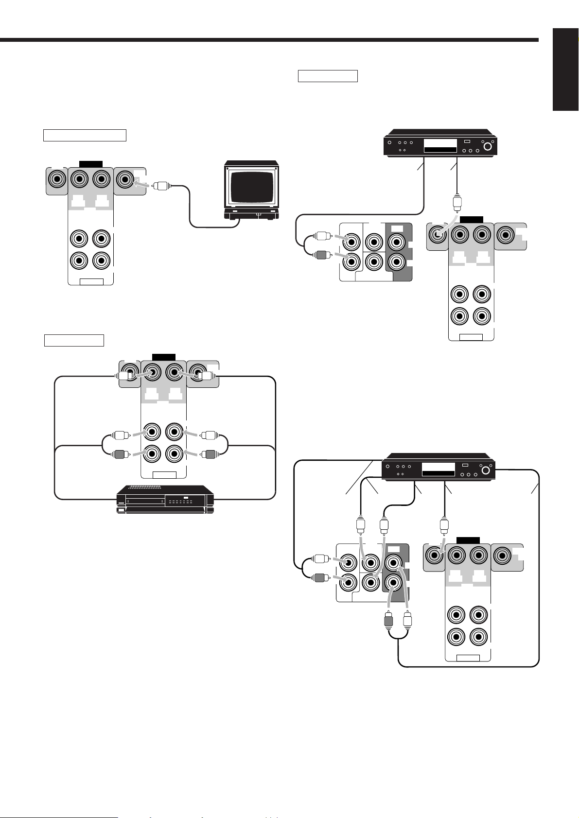
Video component connections
Use the cables with RCA pin plugs (not supplied).
Connect the white plug to the audio left jack, the red plug to the
audio right jack and the yellow plug to the video jack.
TV (as the monitor)
TV (or Monitor)
DVD
VIDEO
OUT
(REC)IN(PLAY)
OUT
(REC)IN(PLAY)
AUDIO
VCR
VCR
LEFT
RIGHT
DVD
MONITOR
OUT
OUT
(REC)IN(PLAY)
OUT
(REC)IN(PLAY)
VIDEO
VCR
To video input
MONITOR
OUT
LEFT
DVD player
• When you connect the DVD player with stereo output jacks:
DVD player
DVD
Å ı
DVD
FRONT CENTER REAR
L
R
SUBWOOFER
DVD
LEFT
RIGHT
Å To front left/right channel audio output (or to audio mixed
output if necessary)
ı To video output
• When you connect the DVD player with its analog discrete output
(5.1 CH reproduction) jacks:
VIDEO
OUT
(REC)IN(PLAY)
VCR
OUT
(REC)IN(PLAY)
AUDIO
LEFT
RIGHT
MONITOR
OUT
English
To audio/video
input
DVD player
RIGHT
AUDIO
VHS
Å
ı ljÎ
DVD
To audio/video
VCR
output
DVD
FRONT CENTER REAR
L
R
SUBWOOFER
LEFT
IGHT
DVD
VIDEO
OUT
(REC)IN(PLAY)
VCR
OUT
(REC)IN(PLAY)
AUDIO
LEFT
RIGHT
MONITOR
OUT
Å To front left/right channel audio output
ı To center channel audio output
Ç To subwoofer audio output
Î To video output
‰ To rear left/right channel audio output
6
Page 10
Connecting the Power Cord
English
Before plugging the receiver into an AC outlet, make sure that all
connections have been made.
Plug the power cord into an AC outlet.
Keep the power cord away from the connecting cables and the
antenna. The power cord may cause noise or screen interference.
We recommend that you use a coaxial cable to connect the
antenna, since it is well-shielded against interference.
Note:
The preset settings such as preset channels and sound adjustment
may be erased in a few days in the following cases:
– When you unplug the power cord.
– When a power failure occurs.
CAUTIONS:
• Do not touch the power cord with wet hands.
• Do not pull on the power cord to unplug the cord. When
unplugging the cord, always grasp the plug so as not to damage
the cord.
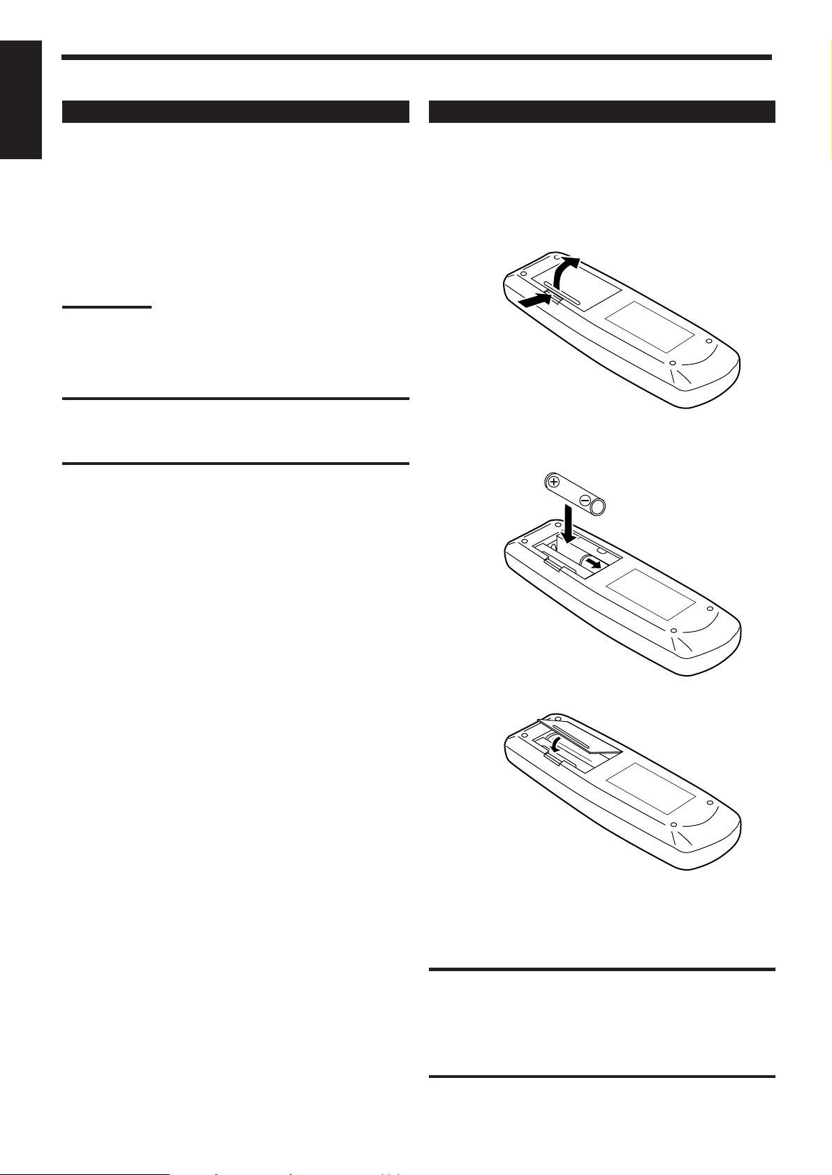
Putting Batteries in the Remote Control
Before using the remote control, put two supplied batteries first.
When using the remote control, aim the remote control directly at
the remote sensor on the receiver.
1. On the back of the remote control, remove the
battery cover as illustrated.
2. Insert batteries. Make sure to observe the proper
polarity: (+) to (+) and (–) to (–).
R6P (SUM-3)/AA (15F)
3. Replace the cover.
If the range or effectiveness of the remote control decreases, replace
the batteries. Use two R6P (SUM-3)/AA (15F) type dry-cell
batteries.
CAUTION:
Follow these precautions to avoid leaking or cracking cells:
• Place batteries in the remote control so they match the polarity
indicated: (+) to (+) and (–) to (–).
• Use the correct type of batteries. Batteries that look similar may
differ in voltage.
• Always replace both batteries at the same time.
• Do not expose batteries to heat or flame.
7
Page 11
Basic Operations
The following operations are commonly used when you play any sound source.
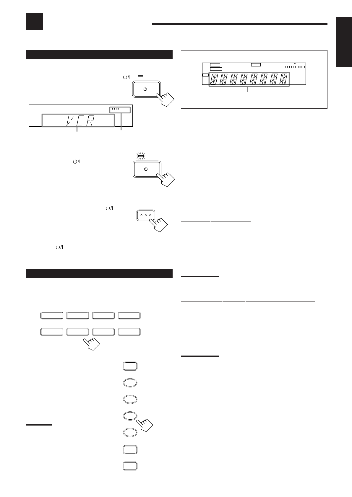
Turning the Power On and Off (Standby)
On the front panel:
To turn on the power, press STANDBY/ON .
The STANDBY lamp goes off. The name of the
current source (or station frequency) appears on
the display.
VOLUME
Current source
name appears
Current volume level
is shown here
To turn off the power (into standby mode),
press STANDBY/ON again.
The STANDBY lamp lights up. A small amount
of power is consumed in standby mode.
To turn the power off completely, unplug the AC
power cord.
From the remote control:
To turn on the power, press AUDIO .
The STANDBY lamp goes off. The name of the
current source (or station frequency) appears on
the display.
To turn off the power (into standby mode),
press AUDIO
again.
The STANDBY lamp lights up.
STANDBY
/I
STANDBY/ON
TANDBY
/I
STANDBYON
AUDIO
MUTE TUNED SLEEP 3D-PHONIC
AUTO STEREO PRO LOGIC
DAP
CH-
L
VOLUME
MHz
kHz
R
Selected source name appears
On the front panel:
DVD MULTI Select the DVD player for viewing the digital video
disc using the analog discrete output mode (5.1CH
reproduction) on the DVD player.
To enjoy the DVD MULTI playback, see page 20.
DVD Select the DVD player for viewing the stereo digital
video disc.
VCR Select the video component connected to the VCR
jacks.
FM Select an FM broadcast.
AM Select an AM broadcast.
TAPE/MD Select the cassette deck (or the MD recorder).
PHONO Select the turntable.
CD Select the CD player.
From the remote control:
FM/AM Select an FM or AM broadcast.
Each time you press the button, the band changes
alternately.
• Other buttons function in the same way as the buttons on the front
panel.
English
Selecting the Source to Play
Press one of the source selecting buttons.
On the front panel:
DVD MUL I
CD
From the remote control:
Note:
When you press one of the source
selecting buttons, marked above
with an asterisk (*), on the remote
control, the receiver automatically
turns on.
DVD
PHONO
VCR
APE/MD
SOURCE NAME
TAPE/MD
DVD MULTI
FM
AM
CD
FM/AM
VCR
DVD
PHONO
Note:
When connecting an MD recorder (to the TAPE/MD jacks), change the
source name that appears on the display. See page 11 for details.
Selecting different sources for picture and sound
You can watch picture from a video component while listening to
sound from another component.
Press one of the audio source selecting buttons (CD, TAPE/MD,
PHONO, FM, AM), while viewing the picture from a video
component such as the VCR or DVD player, etc.
Note:
*
Once you have selected a video source, pictures of the selected
source are sent to the TV until you select another video source.
*
*
*
8
Page 12
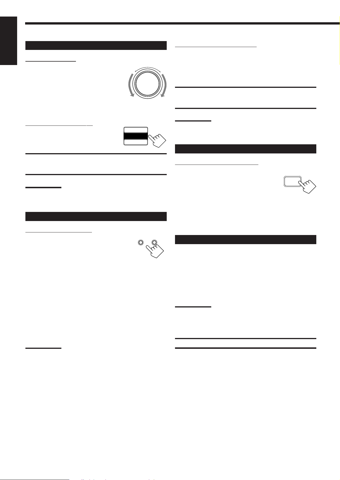
Adjusting the Volume
English
On the front panel:
To increase the volume, turn MASTER
VOLUME clockwise (+).
To decrease the volume, turn it
counterclockwise (–).
• When you turn MASTER VOLUME rapidly,
the volume level also changes rapidly.
• When you turn MASTER VOLUME slowly,
the volume level also changes slowly.
From the remote control:
To increase the volume, press VOLUME +.
To decrease the volume, press VOLUME –.
CAUTION:
Always set the volume to the minimum before starting any source. If
the volume is set at its high level, the sudden blast of sound energy
can permanently damage your hearing and/or ruin your speakers.
Note:
The volume level can be adjusted within the range of “0” (minimum) to
“80” (maximum).
Selecting the Front Speakers
On the front panel ONLY:
When you have connected two pairs of the front
speakers, you can select which to use. Pressing
SPEAKERS 1 or SPEAKERS 2 activates the
respective set of speakers.
• To use the speakers connected to the FRONT SPEAKERS 1
terminals, press SPEAKERS 1 to set it in the _ ON position, and
press SPEAKERS 2 to set it in the — OFF position.
• To use the speakers connected to the FRONT SPEAKERS 2
terminals, press SPEAKERS 2 to set it in the _ ON position, and
press SPEAKERS 1 to set it in the — OFF position.
• To use both sets of the speakers, press SPEAKERS 1 to set it in
the _ ON position, and press SPEAKERS 2 to set it in the _ ON
position.
• To use neither set of the speakers, press SPEAKERS 1 and
SPEAKERS 2 to set them in the — OFF position.
Note:
When only one set of the speakers is connected to either the FRONT
SPEAKERS 1 or 2 terminals, do not activate both pairs of the
speakers. If you do, no sound comes out of the front speakers.
–
+
VOLUME
–
MAS ER VOLUME
+
SPEAKERS
12
_ ON O
Listening only with headphones
1. Connect a pair of headphones to the PHONES jack on the front
panel.
2. Press SPEAKERS 1 and SPEAKERS 2 to set them in the —
OFF position.
CAUTION:
Be sure to turn down the volume before connecting or putting on
headphones, as high volume can damage both the headphones and
your hearing.
Note:
You cannot shut off the sound through the other speakers using the
SPEAKERS 1 and 2 buttons.
Muting the Sound
From the remote control ONLY:
Press MUTING to mute the sound through all
speakers and headphones connected.
MUTING
“MUTING” appears on the display and the
volume turns off (the volume level indicator goes
off).
To restore the sound, press MUTING again.
• Turning MASTER VOLUME or pressing VOLUME +/– also
restores the sound.
Recording a Source
You can record any source playing through the receiver to a cassette
deck (or an MD recorder) connected to the TAPE/MD jacks and the
VCR connected to the VCR jacks at the same time.
While recording, you can listen to the selected sound source at
whatever sound level you like, without affecting the sound levels of
the recording.
Note:
The output volume level, tone adjustment (see page 10), Bass Boost
(see page 10) and DSP modes (see page 15) cannot affect the
recording.
IMPORTANT:
Before recording, turn off the DVD MULTI playback mode.
9
Page 13
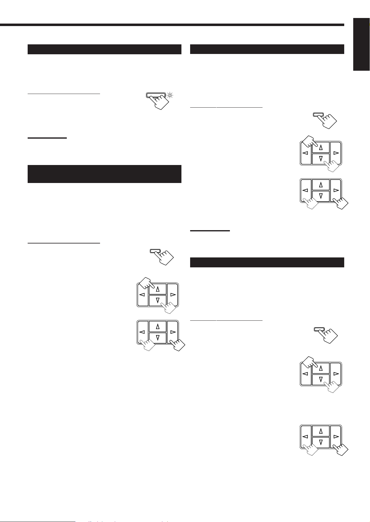
Attenuating the Input Signal
When the input level of the playing source is too high, the sounds
will be distorted. If this happens, you need to attenuate the input
signal level to prevent the sound distortion.
On the front panel ONLY:
Press INPUT ATT. so that the lamp next to
the button lights up.
• Each time you press the button, the Input Attenuator mode turns
on or off.
Note:
When selecting “DVDMULTI” as the source, this effect only applies to
front left and right channel signals.
INPUT ATT .
Adjusting the Front Speaker Output
Balance
If the sounds you hear from the front right and left speakers are
unequal, you can adjust the speaker output balance.
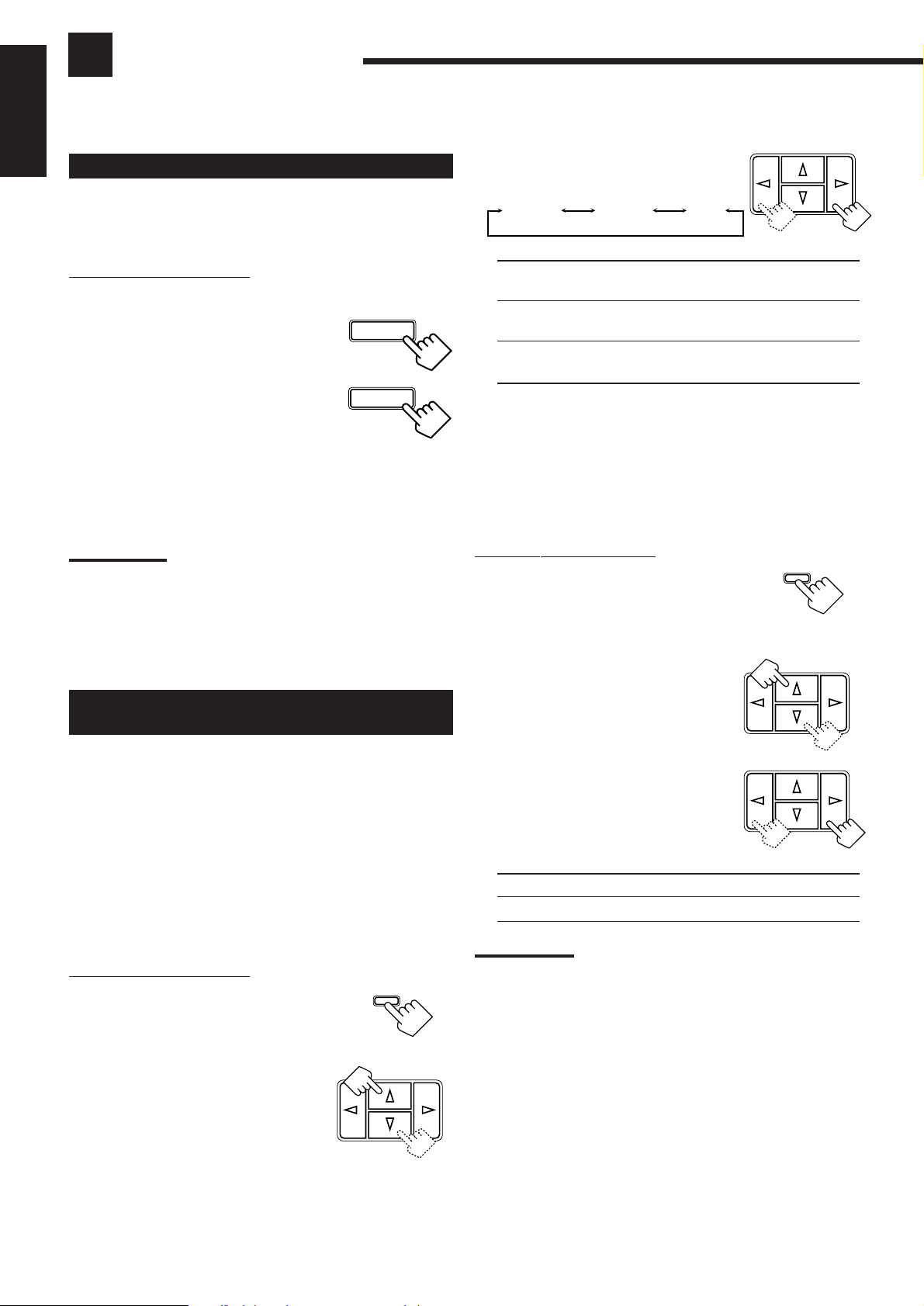
Before y ou start, remember...
• There is a time limit in doing the following steps. If the setting is
canceled before you finish, start from step 1 again.
On the front panel ONLY:
1. Press ADJUST so that MULTI
ADJUST
CURSOR % / fi buttons work for
adjusting the sound.
Reinforcing the Bass
With this Bass Boost function, you can boost the bass level.
Before y ou start, remember...
• There is a time limit in doing the following steps. If the setting is
canceled before you finish, start from step 1 again.
On the front panel ONLY:
1. Press ADJUST so that MULTI
ADJUST
CURSOR % / fi buttons work for
adjusting the sound.
MUL I CURSOR
2. Press MULTI CURSOR % / fi
repeatedly until “B–BOOST”
appears on the display.
3. Press MULTI CURSOR @ / # to
MUL I CURSOR
switch this function “ON” or
“OFF.”
• When this function is switched “ON,” the
BASS BOOST lamp on the front panel
lights up.
Note:
The Bass Boost function affects the front speaker sounds only.
Adjusting the Tone
English
2. Press MULTI CURSOR % / fi
repeatedly until “BALANCE”
appears on the display.
3. Press MULTI CURSOR @ / # to
adjust the balance.
• Pressing @ decreases the right channel
output.
• Pressing # decreases the left channel
output.
MUL I CURSOR
MUL I CURSOR
You can adjust the treble and bass sounds as you like.
Before y ou start, remember...
• There is a time limit in doing the following steps. If the setting is
canceled before you finish, start from step 1 again.
On the front panel ONLY:
1. Press ADJUST so that MULTI
ADJUST
CURSOR % / fi buttons work for
adjusting the sound.
2. Press MULTI CURSOR % / fi
MUL I CURSOR
repeatedly until “– BASS +” or
“–TREBLE+” appears on the
display.
• Select “– BASS +” to adjust the bass sound
level.
• Select “–TREBLE+” to adjust the treble
sound level.
3. Press MULTI CURSOR @ / # to
MUL I CURSOR
adjust the bass or treble sound
level within the range of –10 to
+10.
• Each time you press the button, the sound
level changes by ±2.
10
Page 14
Basic Settings
Some of the following settings are required after connecting and positioning your speakers in your listening room, while
others will make operations easier.
English
Changing the Source Name
When you have connected an MD recorder to the TAPE/MD jacks
on the rear panel: Change the source name shown on the display
when you select the MD recorder as the source.
On the front panel ONLY:
When changing the source name from “TAPE” to “M D”:
TAPE/MD
1. Press T APE/MD .
• Make sure “TAPE” appears on the display.
2. Press and hold SOURCE NAME
(the same button as TAPE/MD)
until “M D” appears on the
display.
To change the source name from “M D” to “TAPE,”
repeat the same procedure above (in step 1, make sure “M D”
appears on the display).
Note:
Without changing the source name, you can still use the connected
components. However, there may be some inconvenience.
– “TAPE” will appear on the display when you select the MD recorder.
– You cannot use the COMPU LINK remote control system (see page
21) to operate the MD recorder.
SOURCE NAME
TAPE/MD
SOURCE NAME
3. Press MULTI CURSOR @ / # to
MUL I CURSOR
select your center speaker size.
LARGE SMALL NO
LARGE: Select this mode when the size of the center speaker
is the same as that of the front speakers.
SMALL: Select this mode when the size of the center speaker
is smaller than that of the front speakers.
NO: Select this mode when you do not use a center
speaker.
Rear Speaker Setting
Register whether you have connected the rear speakers or not.
Before y ou start, remember...
• There is a time limit in doing the following steps. If the setting is
canceled before you finish, start from step 1 again.
On the front panel ONLY:
1. Press SETTING so that MULTI
SETTING
CURSOR % / fi buttons work for
setting the rear speaker
information.
Setting Center and Rear Speakers for
the DSP Modes
To obtain the best possible surround sound of the DSP (Digital
Signal Processor) modes (see page 15), you have to register the
information about the speaker arrangement after all connections are
completed.
Center Speaker Setting
Register the center speaker size.
Before y ou start, remember...
• There is a time limit in doing the following steps. If the setting is
canceled before you finish, start from step 1 again.
On the front panel ONLY:
1. Press SETTING so that MULTI
SETTING
CURSOR % / fi buttons work for
setting the center speaker size.
2. Press MULTI CURSOR % / fi
MUL I CURSOR
repeatedly until “CNTR SPK”
(Center Speaker) appears on the
display.
2. Press MULTI CURSOR % / fi
MUL I CURSOR
repeatedly until “REAR SPK”
(Rear Speaker) appears on the
display.
3. Press MULTI CURSOR @ / # to
MUL I CURSOR
register whether you have
connected the rear speakers.
YES: Select this mode when you use rear speakers.
NO: Select this mode when you do not use rear speakers.
Note:
When you change your speakers, you need to register the information
about the speakers again.
Delay Time Setting
Register the delay time of the sound from the rear speakers,
comparing the sound from the front speakers.
Before y ou start, remember...
• There is a time limit in doing the following steps. If the setting is
canceled before you finish, start from step 1 again.
• You can adjust the delay time only when you have connected the
rear speakers and have set “REAR SPK” to “YES’’ (see above).
• Delay time setting is only valid for “PROLOGIC” (see page 15).
11
Page 15
On the front panel:
ONE TOUCH OPERATION
2010 30 40 50 60 70 80
(Canceled)
0
1. Press SETTING so that MULTI
CURSOR % / fi buttons work for
setting the delay time.
2. Press MULTI CURSOR % / fi
repeatedly until “–DELAY +”
appears on the display.
3. Press MULTI CURSOR @ / # to
select an appropriate delay time.
DELAY 1
DELAY 3
DELAY 2
SETTING
MUL I CURSOR
MUL I CURSOR
To store the sound settings
1. Press ONE TOUCH OPERATION.
The ONE TOUCH OPERATION lamp lights up, then the
previously memorized settings are recalled.
ONE TOUCH
OPERATION
On the remoteOn the front panel
2. Adjust the sound using the functions listed to the
left.
The newly adjusted settings are memorized.
To recall the sound settings
With the ONE TOUCH OPERATION lamp lit, the settings for the
currently selected source are recalled, when the source is selected.
English
DELAY 1: Select this mode when the distance from you to
your rear speakers is greater than that to the front
speakers.
DELAY 2: Select this mode when the distance from you to
your rear speakers is almost equal to that to the
front speakers.
DELAY 3: Select this mode when the distance from you to
your rear speakers is less than that to the front
speakers.
From the remote control:
1. Press SOUND CONTROL.
2. Press SURROUND repeatedly until “PROLOGIC” appears on
the display.
3. Press DELAY repeatedly until an appropriate delay time appears
on the display.
Storing the Basic Settings and
Adjustments — One Touch Operation
JVC’s One Touch Operation function is used to assign and store
different sound settings for each different playing source. By using
this function, you do not have to change the settings every time you
change the source. The stored settings for the newly selected source
are automatically recalled.
The following can be stored for each source:
• Volume level (see page 9)
• Input Attenuator (see page 10)
• Balance (see page 10)
• Bass Boost (see page 10)
• Tone adjustment (see page 10)
• DSP modes
– 3D-PHONIC mode settings (see page 17)
– DAP mode settings (see page 17)
– Surround mode settings (see page 18)
• DVD MULTI playback mode settings (see page 20)
To cancel the One Touch Operation function
Press ONE TOUCH OPERATION so that the lamp goes off.
(Even though the One Touch Operation function is canceled, the
recalled sound effects remain active.)
Notes:
• If the source is FM or AM, you can assign a different setting for
each band.
• The DSP modes and DVD MULTI playback mode cannot be used at
the same time.
Using the Sleep Timer
Using the Sleep Timer, you can fall asleep to music and know the
receiver will turn off by itself rather than play all night.
From the remote control ONLY:
Press SLEEP repeatedly.
The SLEEP indicator lights up on the display,
and the shut-off time changes as follows (in
minutes):
When the shut-off time comes
The receiver turns off automatically.
To check or change the time remaining until the
shut-off time
Press SLEEP once.
The remaining time until the shut-off time appears in minutes.
• To change the shut-off time, press SLEEP repeatedly.
To cancel the Sleep Timer
Press SLEEP repeatedly until “0” appears on the display. (The
SLEEP indicator goes off.)
Turning off the power also cancels the Sleep Timer.
SLEEP
12
Page 16

Receiving Radio Broadcasts
You can browse through all the stations or use the preset function to go immediately to a particular station.
English
Setting the AM Tuner Interval Spacing
Some countries space AM stations 9 kHz apart, and other countries
use 10 kHz spacing. When shipped, the spacing is set to 9 kHz.
On the front panel ONLY:
To select the 10 kHz interval:
Be sure the receiver is tuned off, but is plugged into an AC outlet.
Hold down MULTI CURSOR % and press STANDBY/ON
Now the 10 kHz interval is selected.
MUL I CURSOR
and
To change back to the 9 kHz interval:
Be sure the receiver is tuned off, but plugged into an AC outlet. Hold
down MULTI CURSOR fi and press STANDBY/ON . Now the
9 kHz interval is selected.
MUL I CURSOR
and
STANDBY
/I
STANDBY/ON
STANDBY
/I
STANDBY/ON
Using Preset Tuning
Once a station is assigned to a channel number, the station can be
quickly tuned. You can preset up to 30 FM stations and 15 AM
stations.
To store the preset stations
.
Before y ou start, remember...
• There is a time limit in doing the following steps. If the setting is
canceled before you finish, start from step 1 again.
On the front panel ONLY:
1. Tune in the station you want to preset (see
“Tuning in Stations Manually”).
If you want to store the FM reception mode for this station,
select the FM reception mode you want. See “Selecting the FM
Reception Mode”.
2. Press MEMORY.
“CH-” appears and the channel number
position starts flashing on the display for
about 5 seconds.
CH-
_ _
MEMORY
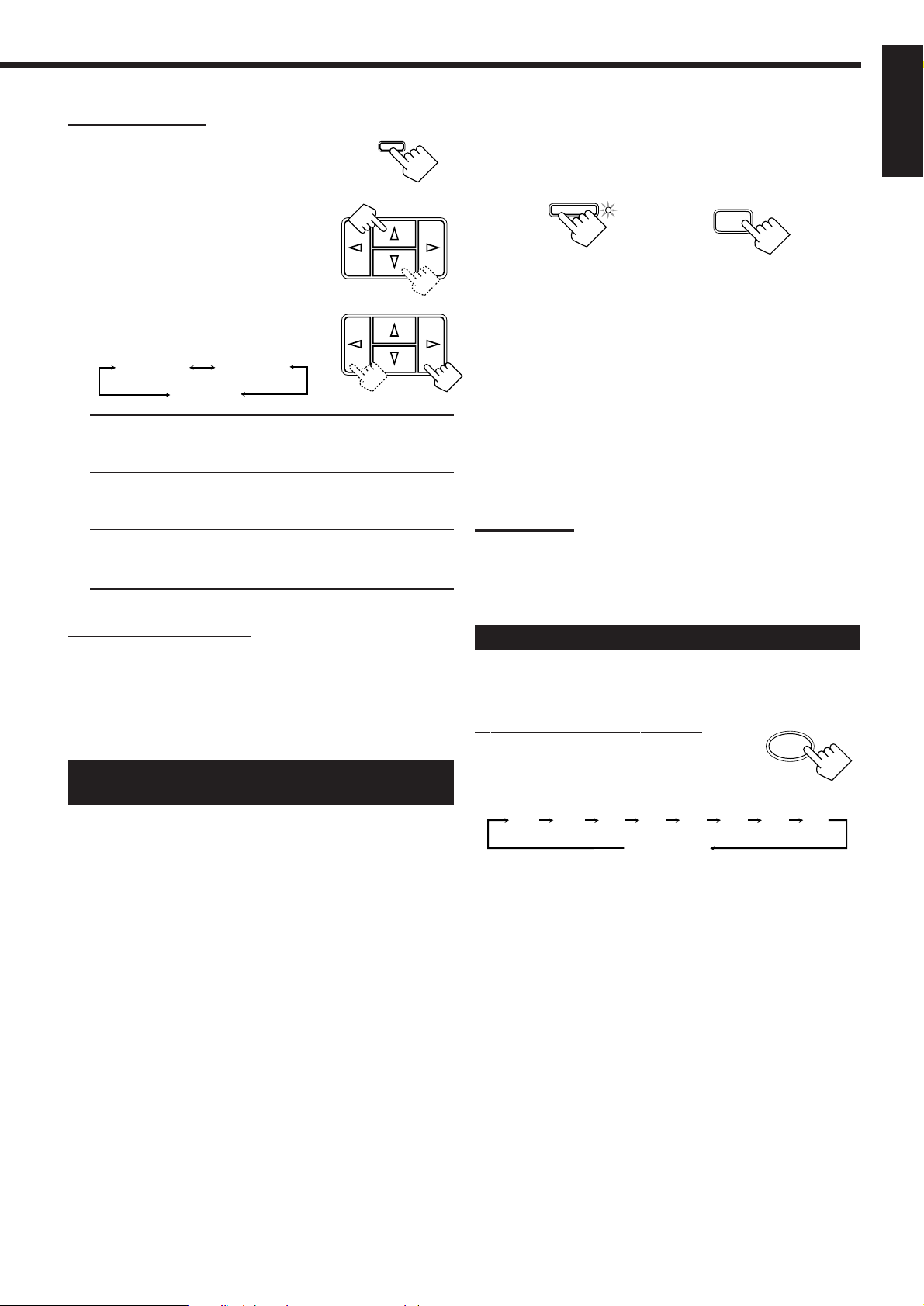
Tuning in Stations Manually
On the front panel ONLY:
1. Press FM or AM.
The last station of the selected band is tuned
in.
• MULTI CURSOR % / fi / @ / # buttons
can be now used for operating the tuner.
2. Press MULTI CURSOR % / fi
repeatedly until “–TUNING+”
appears on the display.
3. Press MULTI CURSOR @ / #
until you find the frequency you
want.
• Pressing @ decreases the frequency.
• Pressing # increases the frequency.
FM
AM
MUL I CURSOR
MUL I CURSOR
3. Press MULTI CURSOR @ / # to
MUL I CURSOR
select a channel number while the
channel number position is
flashing.
Note:
You can use the 10 keys on the remote control to select the preset
number. When using the 10 keys, be sure that they are activated
for the tuner, not for the CD and others. (See page 22.)
4. Press MEMORY again while the
MEMORY
selected channel number is
flashing on the display.
The selected channel number stops flashing.
The station is assigned to the selected channel number.
5. Repeat steps 1 to 4 until you store all the stations
you want.
To erase a stored preset station
Storing a new station on a used number erases the previously stored
one.
Notes:
• When you hold MULTI CURSOR @ / # in step 3, the frequency
keeps changing until a station is tuned in.
• When a station of sufficient signal strength is tuned in, the TUNED
indicator lights up on the display.
When an FM stereo program is received, the STEREO indicator
also lights up.
13
Page 17

To tune in a preset station
On the front panel:
1. Press FM or AM.
The last station of the selected band is tuned
in.
• MULTI CURSOR % / fi / @ / # buttons
can be now used for operating the tuner.
2. Press MULTI CURSOR % / fi
repeatedly until “–PRESET+”
appears on the display.
3. Press MULTI CURSOR @ / # to
select a preset channel station.
• Pressing @ decreases the preset channel
number.
• Pressing # increases the preset channel
number.
FM
AM
MUL I CURSOR
MUL I CURSOR
Selecting the FM Reception Mode
When an FM stereo broadcast is hard to
receive or noisy
You can change the FM reception mode while receiving an FM
broadcast.
On the front panel ONLY:
1. Press FM.
The last station of the selected band is tuned
in.
• MULTI CURSOR % / fi / @ / # buttons
can be now used for operating the tuner.
2. Press MULTI CURSOR % / fi
FM
MUL I CURSOR
repeatedly until “FM MODE”
appears on the display.
English
From the remote control:
FM/AM
1. Press FM/AM.
The last station is tuned in.
• Each time you press the button, the band
alternates between FM and AM.
SURROUND
EFFECT
7/P
TESTDELAY
5
321
CENTER +
5
54
6
REAR•L +
5
98
REAR•R +
+10
10
2. Press the 10 keys to select a preset
channel number.
• For channel number 5, press 5.
• For channel number 15, press +10 then 5.
• For channel number 20, press +10 then 10.
• For channel number 30, press +10, +10,
then 10.
Note:
When you use the 10 keys on the remote control, be sure that they
are activated for the tuner, not for the CD and others. (See page 22.)
3. Press MULTI CURSOR @ / # to
MUL I CURSOR
switch the FM reception “FM
MONO” or “FM AUTO.”
5
MENU
EN
FM MONO: Reception will be improved although you will lose
the stereo effect. In this mode, you will hear noise while
tuning into the stations. The MUTE AUTO indicator
goes off on the display.
FM AUTO: When a program is broadcasted in stereo, you will
hear stereo sound; when in monaural, you will hear
monaural sounds. This mode is also useful to suppress
static noise between stations. The MUTE AUTO
indicator lights up on the display.
14
Page 18

Using the DSP Modes
DOLBY SURROUND
DOLBY SURROUND
The built-in Surround Processor provides three types of the DSP (Digital Signal Processor) mode — 3D-PHONIC mode,
DAP (Digital Acoustic Processor) mode and Surround mode (Dolby Pro Logic and JVC Theater Surround).
English
3D-PHONIC modes
The 3D-PHONIC mode gives you such a nearly surround effect as it
is reproduced through the Dolby Surround decoder, which is widely
used to reproduce sounds with a feeling of movement like those
experienced in movie theaters. The 3D-PHONIC mode is the result
of research on sound localization technology carried out at JVC for
many years. This mode can be used when two front speakers ar e
connected to this receiver (without respect to the rear/center
speaker connection).
You can select either 3D ACTION or 3D THEATER to your
preference.
3D ACTION: Best for action and war movies — where the
action is fast and explosive.
3D THEA TER: Reproduces the sound field of a large theater.
Surround Modes
With this receiver, you can use two types of the Surround modes.
• Dolby Surround
Dolby Surround has been developed to reproduce the important
elements of the acoustic surround at home.
To watch the soundtracks of video software bearing the mark
* which includes the same encoded surround
information as found in Dolby Stereo films, the receiver can provide
you with Dolby Surround decoder.
There are two types of Dolby Surround – “Pro Logic” and “3
Stereo.”
“Pro Logic” can be used when the front speakers and rear
speakers are connected to this receiver (regardless of the center
speaker connection). On the other hand, “3 Stereo” can be used
when the rear speakers are not connected (center speaker must
be connected).
• JVC Theater Surround
In order to reproduce a more realistic sound field in your listening
room while playing soundtracks of video software bearing the mark
, JVC Theater Surround has been designed to give
you clearer vocals and to create a real “being there” feeling.
This mode can be used when the front speakers and rear
speakers are connected to this receiver (without respect to the
center speaker connection).
DAP modes
The sound heard in a concert hall or club consists of direct sound
and indirect sound — early reflections and reflections from behind.
Direct sounds reach the listener directly without any reflection. On
the other hand, indirect sounds are delayed by the distances of the
ceiling and walls. These direct sounds and indirect sounds are the
most important elements of the acoustic surround effects. The DAP
mode can create these important elements, and gives you a real
“being there” feeling. This mode can be used when the front
speakers are connected to this receiver (without respect to the
rear/center speaker connection).
You can select one of the following to your preference.
DANCE CLUB:Gives a throbbing bass beat.
LIVE CLUB: Gives the feeling of a live music club with a low
ceiling.
HALL: Gives clear vocal and the feeling of a concert hall.
PAVILION: Gives the spacious feeling of a pavilion with a high
ceiling.
Reflections from
Early reflections
behind
Notes:
• The DSP modes have no effect on monaural sources.
• The DSP modes cannot be used for recording.
• When you select “DVDMULTI” as the source to play, you cannot
select or adjust the DSP modes.
IMPORTANT:
Before recording, turn off the DVD MUL TI playback mode.
As for the DVD MULTI playback mode, see
page 20.
15
Direct sounds
*
Manufactured under license from Dolby Laboratories Licensing
Corporation. “Dolby,” the double-D symbol, and “Pro Logic” are
trademarks of Dolby Laboratories Licensing Corporation.
Page 19
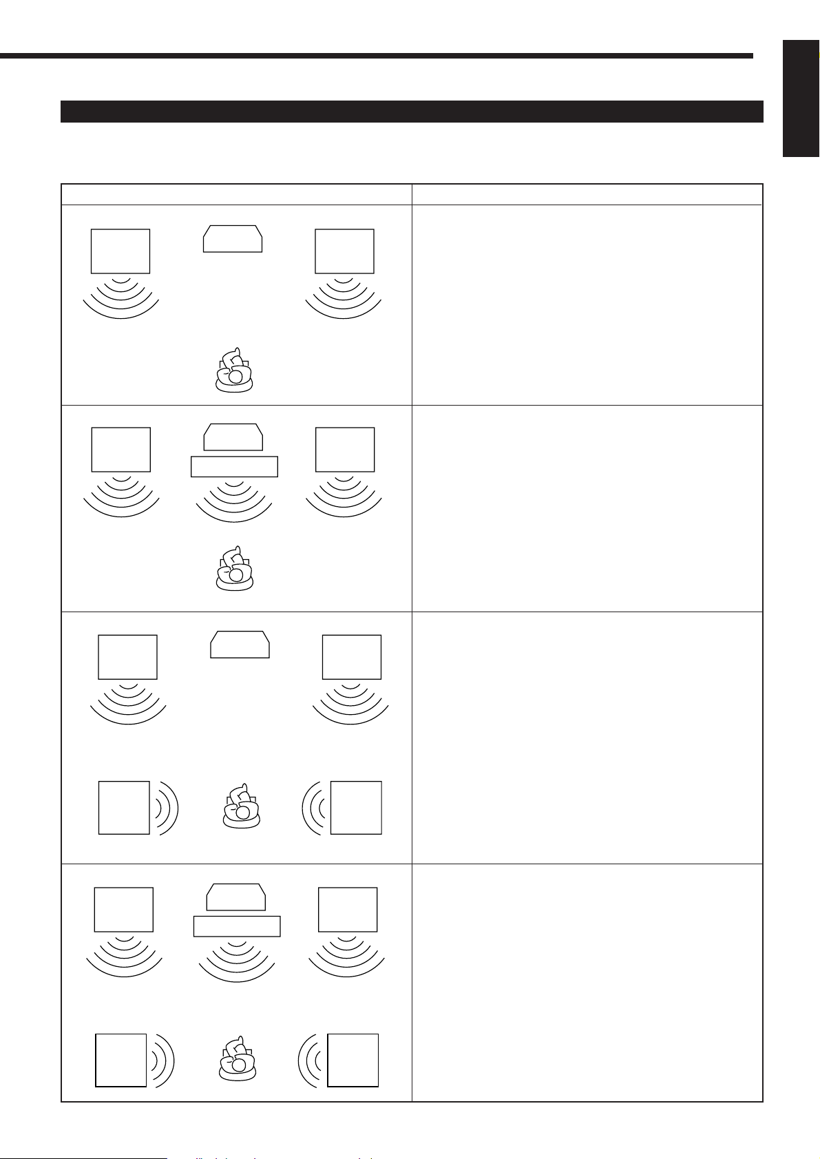
Available DSP Modes According to the Speaker Arrangement
Available DSP modes will vary depending on how many speakers are used with this receiver.
Make sure that you have set the speaker information correctly (see page 11).
English
Front
speaker
Front
speaker
Speaker arrangements
TV
TV
Center speaker
Front
speaker
Front
speaker
Available DSP modes
Each time you press SURROUND, the DSP modes change as
follows:
• 3D THEATER
• DANCE C (DANCE CLUB)
• LIVE C (LIVE CLUB)
• HALL
• PAVILION
• 3D ACTION
• OFF (DSP mode is canceled)
Each time you press SURROUND, the DSP modes change as
follows:
• 3 STEREO
• 3D THEATER
• DANCE C (DANCE CLUB)
• LIVE C (LIVE CLUB)
• HALL
• PAVILION
• 3D ACTION
• OFF (DSP mode is canceled)
Front
speaker
Rear
speaker
Front
speaker
Rear
speaker
TV
TV
Center speaker
Front
speaker
Rear
speaker
Front
speaker
Rear
speaker
Each time you press SURROUND, the DSP modes change as
follows:
• PRO LOGIC
• THEATER
• DANCE C (DANCE CLUB)
• LIVE C (LIVE CLUB)
• HALL
• PAVILION
• 3D ACTION
• OFF (DSP mode is canceled)
Each time you press SURROUND, the DSP modes change as
follows:
• PRO LOGIC
• THEATER
• DANCE C (DANCE CLUB)
• LIVE C (LIVE CLUB)
• HALL
• PAVILION
• 3D ACTION
• OFF (DSP mode is canceled)
16
Page 20

Adjusting the 3D-PHONIC Modes
English
Before y ou start, remember...
• Make sure that you have set the speaker information correctly
(see page 11).
• There is a time limit in doing the following steps. If the setting is
canceled before you finish, start from step 1 again.
On the front panel:
1. Press SURROUND repeatedly until
“3DACTION” or “3DTHEATR”
appears on the display.
The 3D-PHONIC and PRO LOGIC indicators also light up on
the display.
2. Press ADJUST so that MULTI
CURSOR % / fi / @ / # buttons
work for adjusting the surround
setting.
3. Press MULTI CURSOR % / fi
repeatedly until “–EFFECT+”
appears on the display.
4. Press MULTI CURSOR @ / # to
select an effect level you want.
• Each time you press the button, the effect
level changes as follows:
EFFECT 1 EFFECT 2
EFFECT 5
As the number increases, the selected 3D-PHONIC mode
becomes stronger.
From the remote control:
1. Press SOUND CONTROL.
The 10 keys are activated for sound adjustments.
2. Press SURROUND repeatedly until
“3DACTION” or “3DTHEATR”
appears on the display.
The 3D-PHONIC and PRO LOGIC indicators also light up on
the display.
3. Press EFFECT to select an effect
level you want.
• Each time you press the button, the effect
level changes as follows:
EFFECT 1 EFFECT 2
EFFECT 5
As the number increases, the selected 3D-PHONIC mode
becomes stronger.
EFFECT 4
EFFECT 3
EFFECT 4
EFFECT 3
SURROUND
ADJUST
MUL I CURSOR
MUL I CURSOR
SOUND
CONTROL
SURROUND
3
EFFECT
4
Adjusting the DAP Modes
Before y ou start, remember...
• Make sure that you have set the speaker information correctly
(see page 11).
• There is a time limit in doing the following steps. If the setting is
canceled before you finish, start from step 1 again.
• You can only adjust the rear speaker output level when you have
connected the rear speakers and have set “REAR SPK” to “YES”
(see page 11).
On the front panel:
1. Press SURROUND repeatedly
SURROUND
until the DAP mode — DANCE
CLUB, LIVE CLUB, HALL, or
PAVILION — appears on the
display.
The DAP indicator also lights up on the display.
2. Press ADJUST so that MULTI
ADJUST
CURSOR % / fi / @ / # buttons
work for adjusting the DSP
setting.
3. Press MULTI CURSOR % / fi
MUL I CURSOR
repeatedly until “– REAR +”
appears on the display.
4. Press MULTI CURSOR @ / # to
MUL I CURSOR
adjust the rear speaker output
level (from –10 to +10).
Note:
You cannot adjust the left and right rear speaker output levels
separately.
5. Press MULTI CURSOR % / fi
MUL I CURSOR
repeatedly until “–EFFECT+”
appears on the display.
6. Press MULTI CURSOR @ / # to
MUL I CURSOR
select an effect level you want.
5
• Each time you press the button, the effect
level changes as follows:
EFFECT 1 EFFECT 2
EFFECT 5
As the number increases, the selected DAP mode becomes
stronger.
EFFECT 3
EFFECT 4
17
Page 21

From the remote control:
1. Press SOUND CONTROL.
The 10 keys are activated for sound adjustments.
2. Press SURROUND repeatedly
until the DAP mode — DANCE
CLUB, LIVE CLUB, HALL, or
PAVILION — appears on the
display.
The DAP indicator also lights up on the display.
3. Press REAR•L – / + to adjust the
rear speaker output level.
• Pressing REAR•L – decreases the output
level up to –10 dB.
• Pressing REAR•L + increases the output
level up to +10 dB.
SOUND
CONTROL
SURROUND
3
– REAR•L +
5
3. Press TEST to check the speaker
output balance.
“TEST” starts flashing on the display, and a
test tone comes out of the speakers in the
following order:
Left front speaker
Rear speaker
Note:
You can adjust the speaker output levels without outputting the
test tone.
Center speaker
Right front speaker
TEST
2
5
English
98
4. Press CENTER – / + repeatedly to
adjust the center speaker output
– CENTER +
5
6
5
level (from –10 to +10).
Note:
You cannot adjust the left and right rear speaker output levels
separately.
4. Press EFFECT to select an effect
level you want.
• Each time you press the button, the effect
level changes as follows:
EFFECT 1 EFFECT 2
EFFECT 5
As the number increases, the selected DAP mode becomes
stronger.
EFFECT 3
EFFECT 4
EFFECT
4
5
Adjusting the Surround Modes — Dolby
Surround and JVC Theater Surround
Before y ou start, remember...
• Make sure that you have set the speaker information correctly
(see page 11).
• There is a time limit in doing the following steps. If the setting is
canceled before you finish, start from step 1 again.
• You can only adjust the effect level when selecting JVC Theater
Surround.
• You can only adjust the rear and/or center speaker output levels
when you have connected rear speakers and/or a center speaker
and have set “REAR SPK” and/or “CNTR SPK” correctly. See
page 11.
5. Press REAR•L – / + to adjust the
– REAR•L +
5
rear speaker output level (from
–10 to +10).
Notes:
• You cannot adjust the left and right rear speaker output levels
separately.
• You cannot use the REAR•R – / + buttons to adjust the rear
speaker output level.
6. Press TEST again to stop the test
tone.
7. ONLY FOR JVC Theater
Surround:
Press EFFECT to select an effect
level you want.
• Each time you press the button, the effect
level changes as follows:
EFFECT 1 EFFECT 2
EFFECT 5
As the number increases, JVC Theater Surround becomes
stronger.
EFFECT 3
EFFECT 4
TEST
5
2
EFFECT
4
98
5
From the remote control:
1. Press SOUND CONTROL.
The 10 keys are activated for sound adjustments.
2. Press SURROUND repeatedly
SOUND
CONTROL
SURROUND
until the mode — “PROLOGIC,”
“3 STEREO,” or “THEATER” —
appears on the display.
• For “PROLOGIC” and “3 STEREO,” the PRO LOGIC
indicator lights up on the display.
• For “THEATER,” the PRO LOGIC and DAP indicators light
up on the display.
3
18
Page 22

On the front panel:
You can also use the buttons on the front panel to adjust the
English
Surround modes. However, no test tone is available when using the
buttons on the front panel. So, make adjustments while listening to
the sound of the source played back.
1. Press SURROUND repeatedly
until the mode — “PROLOGIC,”
“3 STEREO,” or “THEATER”—
appears on the display.
The PRO LOGIC indicator lights up on the display.
SURROUND
8. ONLY FOR JVC Theater
Surround:
Press MULTI CURSOR @ / # to
select an effect level you want.
• Each time you press the button, the effect
level changes as follows:
EFFECT 1 EFFECT 2
EFFECT 5
MUL I CURSOR
EFFECT 3
EFFECT 4
2. Press ADJUST so that MULTI
CURSOR % / fi / @ / # buttons
work for adjusting the DSP
setting.
3. Press MULTI CURSOR % / fi
repeatedly until “–CENTER+”
appears on the display.
4. Press MULTI CURSOR @ / # to
adjust the center speaker output
level (from –10 to +10).
5. Press MULTI CURSOR % / fi
repeatedly until “– REAR +”
appears on the display.
6. Press MULTI CURSOR @ / # to
adjust the rear speaker output
level (from –10 to +10).
ADJUST
MUL I CURSOR
MUL I CURSOR
MUL I CURSOR
MUL I CURSOR
As the number increases, JVC Theater Surround becomes
stronger.
Activating the DSP Modes
Once you have finished adjustments for the DSP modes, you can use
the same adjustments every time you want to use these modes.
On the front panel:
SURROUND
1. Press SURROUND repeatedly
until the DSP mode you want
appears on the display.
• Each time you press the button, the DSP modes change. (See
page 16 for more details.)
2. Select and play a sound source.
• To enjoy the 3D-PHONIC, Dolby Surround, and JVC Theater
Surround, play back a software which was processed with
Dolby Surround and is labeled with
DOLBY SURROUND
To cancel the DSP mode
Press SURROUND repeatedly until “OFF” appears on the display.
From the remote control:
1. Press SOUND CONTROL.
The 10 keys are activated for sound adjustments.
mark.
SOUND
CONTROL
Note:
You cannot adjust the left and right rear speaker output levels
separately.
7. ONLY FOR JVC Theater
Surround:
Press MULTI CURSOR % / fi
repeatedly until “–EFFECT+”
appears on the display.
19
MUL I CURSOR
2. Press SURROUND repeatedly
until the DSP mode you want
appears on the display.
• Each time you press the button, the DSP
modes change. (See page 16 for more
details.)
SURROUND
3
3. Select and play a sound source.
• To enjoy the 3D-PHONIC, Dolby Surround, and JVC Theater
Surround, play back a software which was processed with
Dolby Surround and is labeled with
To cancel the DSP mode
Press SURROUND repeatedly until “OFF” appears on the display in
step 2 above.
DOLBY SURROUND
mark.
Page 23

Using the DVD MULTI Playback Mode
This receiver provides the DVD MULTI playback mode for reproducing the analog discrete output mode of the DVD
player. Before playing back a DVD, refer also to the manual supplied with the DVD player.
MUL I CURSOR
MUL I CURSOR
MUL I CURSOR
Activating the DVD MULTI Playback Mode
You can adjust the DVD MULTI playback mode while playing back
a DVD using the analog discrete output mode on the DVD player.
Once you made adjustments, the receiver memorizes the
adjustments until you change them.
Before y ou start, remember...
• Make sure that you have set the speaker information correctly
(see page 11).
• There is a time limit in doing the following steps. If the setting is
canceled before you finish, start from step 1 again.
• You can only adjust the rear and/or center speaker output levels
when you have connected rear speakers and/or a center speaker
and have set “REAR SPK” and/or “CNTR SPK” correctly. See
page 11.
7. Press MULTI CURSOR @ / # to
adjust the left rear speaker output
level (from –10 to +10).
8. Press MULTI CURSOR % / fi
repeatedly until “–REAR R+”
appears on the display.
9. Press MULTI CURSOR @ / # to
adjust the right rear speaker
output level (from –10 to +10).
English
On the front panel:
DVD MULTI
1. Press DVD MULTI .
Note:
When you select “DVDMULTI” as the source to play, the DSP
mode is canceled temporarily, and the SURROUND button does
not work.
2. Select the analog discrete output mode on the
DVD player, and start playing a DVD.
• Refer to the manual supplied with the DVD player.
If you need to make any adjustment, go to the following
steps.
3. Press ADJUST so that MULTI
ADJUST
CURSOR % / fi / @ / # buttons
work for adjusting the DVD
MULTI playback setting.
4. Press MULTI CURSOR % / fi
MUL I CURSOR
repeatedly until “–CENTER+”
appears on the display.
From the remote control:
1. Press DVD MULTI.
Note:
When you select “DVDMULTI” as the source to play, the DSP
mode is canceled temporarily, and the SURROUND button does
not work.
DVD MULTI
2. Select the analog discrete output mode on the
DVD player, and start playing a DVD.
• Refer to the manual supplied with the DVD player.
If you need to make any adjustment, go to the following
steps.
SOUND
3. Press SOUND CONTROL.
The 10 keys are activated for adjusting the sound.
4. Press CENTER – / + to adjust the
center speaker output level.
• Pressing CENTER – decreases the output
level up to –10 dB.
• Pressing CENTER + increases the output
level up to +10 dB.
CONTROL
– CENTER +
5
6
5
5. Press MULTI CURSOR @ / # to
adjust the center speaker output
level (from –10 to +10).
6. Press MULTI CURSOR % / fi
repeatedly until “–REAR L+”
appears on the display.
MUL I CURSOR
MUL I CURSOR
5. Press REAR•L – / + to adjust the
left rear speaker output level.
• Pressing REAR•L – decreases the output
level up to –10 dB.
• Pressing REAR•L + increases the output
level up to +10 dB.
6. Press REAR•R – / + to adjust the
right rear speaker output level.
• Pressing REAR•R – decreases the output
level up to –10 dB.
• Pressing REAR•R + increases the output
level up to +10 dB.
– REAR•L +
5
– REAR•R +
10
98
+10
20
Page 24

COMPU LINK Remote Control System
The COMPU LINK remote control system allows you to operate JVC audio components through the remote sensor on
the receiver.
English
To use this remote control system, you need to connect JVC audio
components through the COMPU LINK-3 (SYNCHRO) jacks (see
below) in addition to the connections using cables with RCA pin
plugs (see page 5).
• Make sure that the AC power cords of these components are
unplugged before connection. Plug the AC power cords only after
all connections are complete.
CD player
Cassette deck
or
MD recorder
COMPU LINK – 3
(SYNCHRO)
Turntable
To connect the components, use the cables with monaural
mini plug.
Notes:
• If your audio component has two COMPU LINK-3 (SYNCHRO)
jacks, you can use either one. If it has only one COMPU LINK-3
(SYNCHRO) jack, connect it so that it is the last item in the series
of components. (For example, the turntable or CD player in the
diagram above.)
• To operate the cassette deck or MD recorder using the COMPU
LINK remote control system, set the source name correctly. (See
page 11.)
• Refer also to the manuals supplied with your audio components.
This remote control system allows you to use four functions listed
below.
Remote Control through the Remote Sensor on the
Receiver
You can control the connected audio components through the remote
sensor on the receiver using this remote control. Aim the remote
control directly at the remote sensor on the receiver. For details, see
pages 22 and 23.
Automatic Power On/Off (Standby): only possible
with the COMPU LINK-3 connection
Both the CD player and cassette deck (or MD recorder) turn on and
off (standby) along with the receiver.
When you turn on the receiver, the CD player or cassette deck (or
MD recorder) will turn on automatically, depending on which
component has been previously selected.
When you turn off the receiver, both the CD player and cassette
deck (or MD recorder) will turn off (standby).
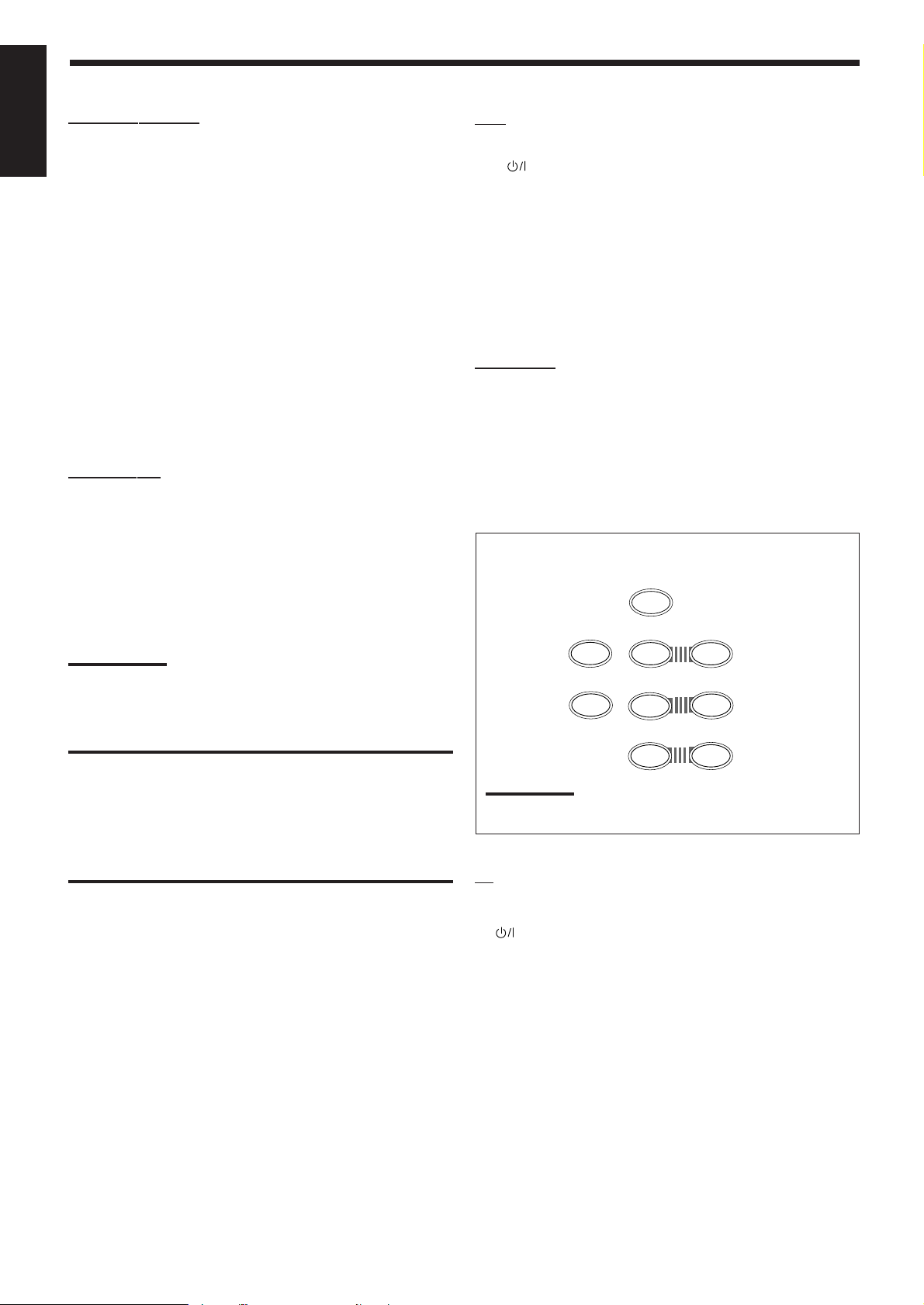
Synchronized Recording
Synchronized recording means the cassette deck (or MD recorder)
starts recording as soon as a CD or a record begins playing.
To use synchronized recording, follow these steps:
1. Put a tape in the cassette deck (or an MD in the
MD recorder), and a disc in the CD player (or a
record on the turntable).
2. Press the record (¶) button and the pause (8)
button on the cassette deck (or MD recorder) at
the same time.
This puts the cassette deck (or MD recorder) into recording
pause.
If you do not press the record (¶) button and pause (8) button at
the same time, the synchronized recording feature will not
operate.
3. Press the play (3) button on the CD player or on
the turntable.
The source changes on the receiver, and as soon as play starts,
the cassette deck (or MD recorder) starts recording. When the
play ends, the cassette deck (or MD recorder) enters recording
pause, and stops about 4 seconds later.
Notes:
• During synchronized recording, the selected source cannot be
changed.
• If the power of any component is shut off during synchronized
recording, the COMPU LINK remote control system may not
operate properly. In this case, you must start again from the
beginning.
Automatic Source Selection
When you press the play (3) button on a connected component or
on its own remote control, the receiver automatically turns on and
changes the source to the component. On the other hand, if you
select a new source on the receiver or the remote control, the
selected component begins playing immediately.
In both cases, the previously selected source continues playing
without sound for a few seconds.
21
Page 25

Operating JVC’s Audio/Video Components
You can operate JVC’s audio and video components with this receiver’s remote control, since control signals for JVC
components are preset in the remote control.
IMPORTANT:
To operate JVC’s audio components using this remote control:
• You need to connect JVC audio components through the COMPU
LINK-3 (SYNCHRO) jacks (see page 21) in addition to the
connections using cables with RCA pin plugs (see page 5).
• Aim the remote control directly at the remote sensor on the
receiver.
• If you use the buttons on the front panel to choose a source, the
remote control will not operate that source. To operate a source
with the remote control, the source must be selected using buttons
on the remote control.
• Refer also to the manuals supplied with your components.
TV
CD
TAPE/MD
FM/AM
VCR
DVD
DVD MULTI
PHONO
ONE OUCH
OPERA ION
MUTING
SLEEP
8
EFFECT
SOUND
CON ROL
CD DISC
TV/VIDEO
4
1
7/P
5
+
VOLUME
–
VCR
TESTDELAY
5
CENTER +
54
REAR•L +
5
REAR•R +
10
TV VOL.
–
TV CH
–
£
7
AUDIO
SURROUND
321
6
98
+10
+
+
+
VCR CH
–
5
MENU
EN
4
1
Sound control section (Amplifier)
After pressing SOUND CONTROL, you can perform the following
operations:
SURROUND: Selects the DSP modes.
CENTER – / +: Adjusts the center speaker output level for the
Surround/DVD MULTI playbac k modes.
REAR•L – / +: Adjusts the left/right rear speaker output level for
the DSP modes.
Adjusts the left rear speaker output level for the
DVD MULTI playbac k mode.
REAR•R – / +: Adjusts the right rear speaker output level for the
DVD MULTI playbac k mode.
DELA Y: Selects the delay time of the rear speaker sound.
(Only works when “PROLOGIC” is selected.)
EFFECT: Selects the effect level for the DSP modes.
TEST: Turns on or off the test tone output for the
Surround mode.
Note:
After adjusting sounds, press the corresponding source selecting
button or CD-DISC to operate your target source by using the 10
keys; otherwise, the 10 keys cannot be used for operating your target
source.
Cassette deck
After pressing TAPE/MD, you can perform the following operations
on a cassette deck:
3: Starts playing.
1: Fast winds the tape from right to left.
¡: Fast winds the tape from left to right.
7: Stops operations.
8: Pauses playing. To release it, press 3.
Note:
To operate the cassette deck or MD recorder using the COMPU LINK
remote control system, set the source name correctly. (See page 11.)
English
RM-SR558XU REMOTE CONTROL
Tuner
After pressing FM/AM, you can perform the following operations:
FM/AM: Alternates between FM and AM.
1 – 10, +10: Selects a preset channel number directly.
For channel number 5, press 5.
For channel number 15, press +10, then 5.
For channel number 20, press +10, then 10.
CD player
After pressing CD, you can perform the following operations on the
CD player:
3: Starts playing.
4: Returns to the beginning of the current (or
4
previous) track.
¢: Skips to the beginning of the next track.
¢
7: Stops playing.
8: Pauses playing. To release it, press 3.
1 – 10, +10: Selects a track number directly.
For track number 5, press 5.
For track number 15, press +10, then 5.
For track number 20, press +10, then 10.
22
Page 26
CD player-changer
After pressing CD-DISC, you can perform the following operations
English
on a CD player-changer:
3: Starts playing.
4: Returns to the beginning of the current (or previous)
track.
¢: Skips to the beginning of the next track.
7: Stops playing.
8: Pauses playing. To release it, press 3.
1 – 6, 7/P: Selects the number of a disc installed in a CD
player-changer.
After pressing CD, you can perform the following operations on the
CD player-changer:
1 – 10, +10: Selects a track number directly.
For track number 5, press 5.
For track number 15, press +10, then 5.
For track number 20, press +10, then 10.
MD recorder
After pressing TAPE/MD, you can perform the following operations
on the MD recorder:
3: Starts playing.
4: Returns to the beginning of the current (or previous)
track.
¢: Skips to the beginning of the next track.
7: Stops playing.
8: Pauses playing. To release it, press 3.
Note:
To operate the cassette deck or MD recorder using the COMPU LINK
remote control system, set the source name correctly. (See page 11.)
IMPORTANT:
To operate JVC’s video components using this remote control:
• Aim the remote control directly at the remote sensor on the VCR,
DVD player or TV, not on the receiver.
• Some JVC VCRs can accept two types of the control signals —
remote code “A” and “B.” Before using this remote control, make
sure that the remote control code of the VCR connected to the
VCR jacks is set to code “A.”
VCR
You can always perform the following operations :
VCR
:Turns on or off the VCR.
VCR CH +/–: Changes the channels on the VCR.
After pressing VCR, you can perform the following operations on
the VCR:
3: Starts playing.
1: Rewinds a tape.
¡: Fast winds a tape.
7: Stops operations.
8: Pauses playing. To release it, press 3.
DVD player
After pressing DVD or DVD MULTI, you can perform the following
operations on a DVD player:
3: Starts playing.
4: Returns to the beginning of the current (or previous)
track.
¢: Skips to the beginning of the next track.
7: Stops playing.
8: Stops playing temporarily. To release it, press 3.
After pressing DVD or DVD MULTI, these buttons can be used
for the DVD menu operations.
TEST
5
2
EFFECT
5
7/P
Note:
For detailed menu operations, refer to the instructions supplied
with the discs or the DVD player.
– CENTER +
54
– REAR•L +
5
– REAR•R +
10
6
98
MENU
+10
5
ENT
(ENTER)
TV
You can always perform the following operations:
23
TV : Turns on or off the TV.
TV VOL. –/+: Adjusts the volume.
TV/VIDEO: Sets the input mode (either TV or VIDEO).
TV CH –/+: Changes the channels.
Page 27

Troubleshooting
Use this chart to help you solve daily operational problems. If there is any problem you cannot solve, contact your JVC
service center.
PROBLEM
POSSIBLE CAUSE
SOLUTION
English
The display does not light up.
No sound from speakers.
Sound from one speaker only.
Continuous hiss or buzzing during FM
reception.
Occasional cracking noise during FM
reception.
The power cord is not plugged in.
Speaker signal cables are not connected.
The SPEAKERS 1 and 2 buttons are not
set correctly.
An incorrect source is selected.
Muting is activated.
Speaker signal cables are not connected
properly.
The balance is set to one extreme.
Incoming signal is too weak.
The station is too far away.
An incorrect antenna is used.
Antennas are not connected properly.
Ignition noise from automobiles.
Plug the power cord into an AC outlet.
Check speaker wiring and reconnect if
necessary.
Press SPEAKERS 1 and 2 correctly.
Select the correct source.
Press MUTING to cancel the mute.
Check speaker wiring and reconnect if
necessary.
Adjust the balance properly (see page 9).
Connect an outside FM antenna or contact
your dealer.
Select a new station.
Check with your dealer to be sure you have
the correct antenna.
Check connections.
Move the antenna farther from automobile
traffic.
Howling during record playing.
“OVERLOAD” starts flashing on the
display.
Remote control does not work.
Your turntable is too close to speakers.
Speakers are overloaded because of high
volume.
Speakers are overloaded because of short
circuit of speaker terminals.
There is an obstruction in front of the
remote sensor on the receiver.
Batteries are weak.
Move speakers away from the turntable.
Rotate the MASTER VOLUME control
counterclockwise three or four times, then
press STANDBY/ON
If “OVERLOAD” does not disappear, unplug
the AC power cord, then plug it back again.
Press STANDBY/ON
then check the speaker wiring.
If “OVERLOAD” does not disappear, unplug
the AC power cord, then plug it back again.
If speaker wiring is not short-circuited,
contact your dealer.
Remove the obstruction.
Replace batteries.
on the front panel.
on the front panel,
24
Page 28

English
Specifications
Amplifier
Output Power
At Stereo operation: 100 W per channel, min. RMS, both
channels driven into 8 Ω at 1 kHz, with no
more than 0.9% total harmonic distortion.
(IEC268-3/DIN)
At Surround operation:
Front Channel: 70 W per channel, min. RMS, driven into
8 Ω at 1 kHz, with no more than 0.8% total
harmonic distortion.
Center channel: 70 W, min. RMS, driven into 8 Ω at 1 kHz,
with no more than 0.8% total harmonic
distortion.
Rear channel: 70 W per channel, min. RMS, driven into
8 Ω at 1 kHz, with no more than 0.8% total
harmonic distortion.
T otal Harmonic Distortion (8 Ω, 1 kHz):
0.8%* at 100 W output
(* Measured by JVC Audio Analysis
System)
Audio
Audio Input Sensitivity/Impedance (1 kHz):
PHONO (MM): 2.7 mV/47 k Ω
CD, TAPE/MD, VCR, DVD:
220 mV/47 k Ω
Audio Output Level: TAPE/MD, VCR 220 mV
Signal-to-Noise Ratio (’66 IHF/DIN):
PHONO: 70 dB/66 dB
CD, TAPE/MD, VCR, DVD:
87 dB/67 dB
Frequency Response (8 Ω):
PHONO: 20 Hz to 20 kHz (±1 dB)
CD, TAPE/MD, VCR, DVD:
20 Hz to 20 kHz (±1 dB)
RIAA Phono Equalization: ±1.0 dB (20 Hz to 20 kHz)
Video
Video Input Sensitivity/Impedance:
VCR, DVD: 1V(p-p)/75 Ω
25
Video Output Level:
VCR, MONITOR OUT: 1V(p-p)/75 Ω
Synchronization: Negative
Signal-to-Noise Ratio: 45 dB
Page 29

FM tuner (IHF)
Tuning Range: 87.50 MHz to 108.00 MHz
Usable Sensitivity: Monaural: 12.8 dBf (1.20 µV/75 Ω)
50 dB Quieting Sensitivity:
Monaural: 21.3 dBf (3.2 µV/75 Ω)
Stereo: 41.3 dBf (31.5 µV/75 Ω)
Signal-to-Noise Ratio (IHF-A weighted):
Monaural: 78 dB at 85 dBf
Stereo: 73 dB at 85 dBf
Total Harmonic Distortion:
Monaural: 0.4% at 1 kHz
Stereo: 0.6% at 1 kHz
Stereo Separation at REC OUT: 35 dB at 1 kHz
Alternate Channel Selectivity:
45 dB: (±400 kHz)
Frequency Response:30 Hz to 15 kHz: (+0.5 dB, –3 dB)
English
AM tuner
Tuning Range: 531 kHz to 1,602 kHz (at 9 kHz interval)
530 kHz to 1,600 kHz (at 10 kHz interval)
Usable Sensitivity: Loop antenna 400 µV/m
Signal-to-Noise Ratio: 50 dB (100 mV/m)
General
Power Requirements: AC 220 V ,
adjustable with the voltage selector,
50 Hz
Power Consumption: 250 W (at operation)
5 W (in standby mode)
Dimensions (W x H x D): 435 mm x 146 mm x 403.5 mm
Mass: 10.2 kg (22.5 lbs)
3
(17
/16 in. x 5 3/4 in. x 15 15/16 in.)
Designs & specifications are subject to change without notice.
26
Page 30
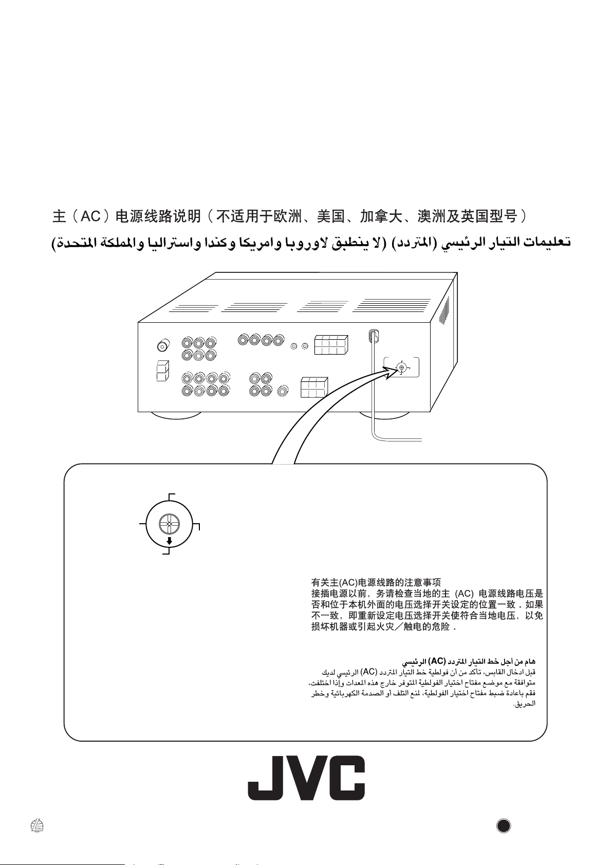
Mains (AC) Line Instruction (not applicable for Europe, U.S.A., Canada, Australia
and U.K.)
Instrucción sobre la línea de la red (CA) (no aplicable para Europa, EE.UU.,
Canadá, Australia, ni el Reino Unido)
Instrução sobre a tensão da rede eléctrica (CA) (não aplicável para a Europa, os
E.U.A., o Canadá, a Austrália e o Reino Unido)
VOLTAGE SELECTOR
127V
110V
230
-240V
220V
VOLTAGE SELECTOR
127V
110V
230
-240V
220V
CAUTION for mains (AC) line
BEFORE PLUGGING IN, do check that your mains (AC)
line voltage corresponds with the position of the voltage
selector switch provided on the outside of this equipment
and, if different, reset the voltage selector switch, to prevent
from a damage or risk of fire/electric shock.
PRECAUCIÓN para la línea de la red (CA)
ANTES DE ENCHUFAR EL EQUIPO, compruebe si la
tensión de la línea de la red (CA) corresponde con la posición
del selector de tensión situado en la parte exterior del equipo,
y si es diferente, reajuste el selector de tensión para evitar el
riesgo de incendios/ descargas eléctricas.
PRECAUÇÃO para a ligação à tensão da rede (CA)
ANTES DE LIGAR O APARELHO A UMA TOMADA DA
REDE, verifique se a tensão da rede CA corresponde à posição
do selector de voltagem localizado na parte externa deste
equipamento. Caso não corresponda, reajuste o selector de
voltagem a fim de evitar avarias ou riscos de incêndio e choque
eléctrico.
EN, SP, PR, CH
VICTOR COMPANY OF JAPAN, LIMITED
JVC
0400HIMMDWJEIN
 Loading...