

Page 1

.rt
-- l-F'rl
r+
6
r*f,
F
.IYE
:
@
Rx-207rN/E&egggK
I I r! l-'rl
RX-307TN/RX-3068K
E_!!l
??rttdt
rbrytttry
t rNU
t tttl
M
CqnlrrolCaz
4
For Customer
Enter
which
tgt]
tom
formation for
Model
Serial No.
Use:
below the Model
located
are
or side
of the cabinet. Retain this in-
No.
t4g.*aa 6
rqrnil
No. and Serial No.
either on the rear,
future reference.
E30580-1 791
(J)
bot-
A
Page 2
WARNING:
F|RE
OR
EXPOSE
TO REDUCE
ELECTRTC
THIS
MOISTURE.
THE RISK OF
SHOCK
DO NOT
AP,PLIANCE TO RAIN
OR
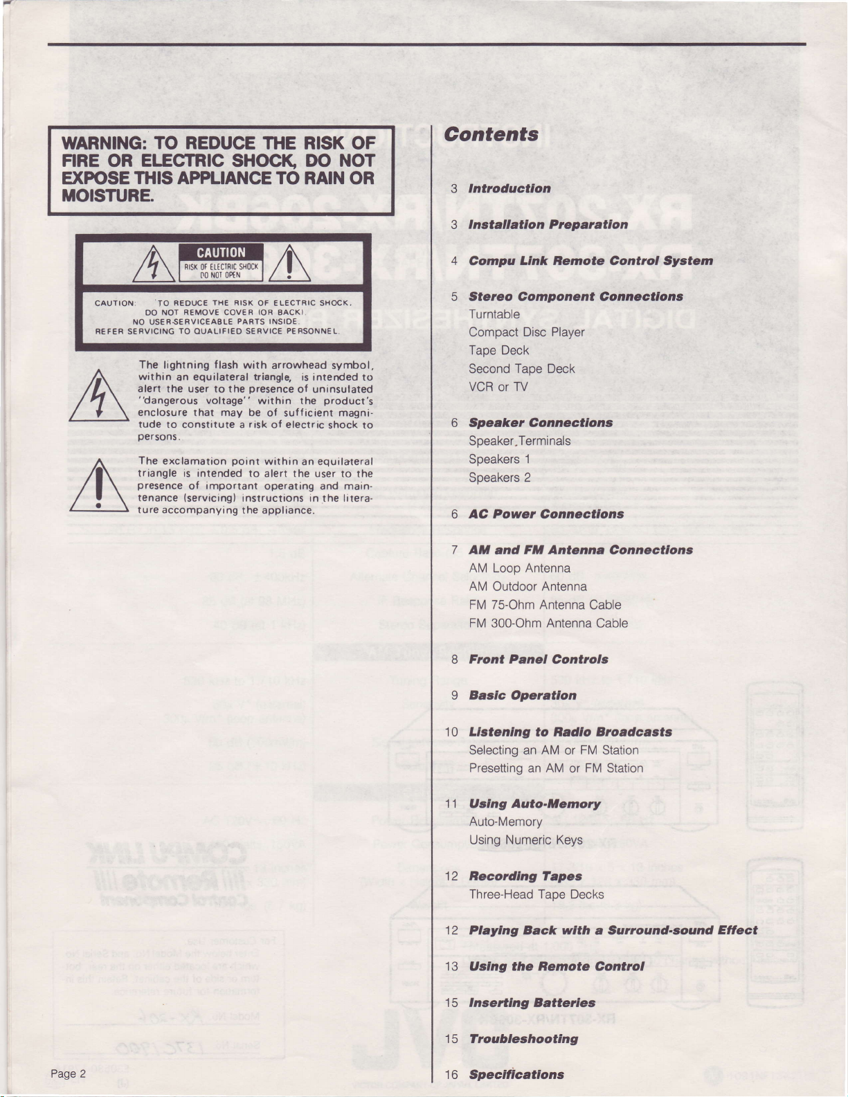
Contents
lntroductlon
3
lnstallatlon
3
Prepantlon
CAUTION:
REF€R SERVICING
REDUCE THe RISK
TO
NOT
DO
NO US€R.S€RVICEABLE
The
lightning f lash wirh
within
an
alert the user to the
"dangerous
enclosure that
tude
to constitute a
persons.
The
exclamation
triangle is intended
presence
tenance
ture accompanying
ntsK
REMOVE
TO
OUALIFIEO
equilateral
of
{servicing}
sHocx
0t tttclRrc
Nol oPtN
00
COVER IOR BACKI,
PARTS INSIOE.
SERVICE
triangle,
voltage" within the
important
Dresence
may be
risk
point
to alert the user
instructions in the lrterathe
OF ELECTRIC SHOCK,
P€RSONN€L,
arrowhead
of sufficient
of electric
within
operating and main-
appliance.
symbol,
is interded to
of uninsulated
product's
magni-
shock to
an equilateral
to the
4
Compu
LInk Bemote Control System
5 Stereo Component Connectlons
Turntable
Compact
Disc Player
Tape Deck
Second
VCR
Taoe Deck
TV
or
Speaker Connecilons
Speaker.Terminals
Speakers
Soeakers
6 AC Power
7
AM and
1
2
Connactlons
F*l
Antenna Connecflons
AM Loop Antenna
AM Outdoor Antenna
FM 75-Ohm Antenna
FM
300-Ohm Antenna Cable
Cable
8 Front Panel Controls
Page 2
9 Basfc Operatlon
Llctenlng to Badlo Broadcasts
10
Selecting an AM or FM Station
Presetting
tl
Uslng Auto-Memory
an AM or FM Station
Auto-Memory
Numeric
Using
Becordlng lapes
12
Three-Head
12
Playlng Back wlth a Sunound-sound
13
Uslng the Hemote Control
tc
lnsertlng Batteiles
froubleehooting
tc
to
Specificatlons
Keys
Tape Decks
Eflect
Page 3
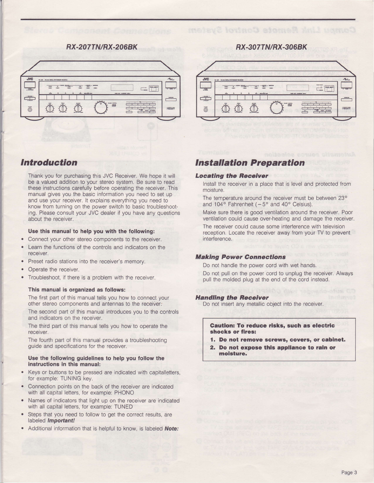
RX-207TN/RX-2068K
RX-307TN/RX-3068K
,IYE
-a
E
:
@
OO
.CI
Introduction
you
Thank
be a valued addition to
these instructions
manual
and use
know from turning
ing.
Please
about the receiver.
Use this manual to help
a
Connect
a
Learn
the
recerver.
a
Preset radio
a
Operate the receiver.
a
Troubleshoot, if
This manual is
The first
other stereo components
The second
indicators
and
The
third
recetver.
The
fourth
guide
and specifications for the receiver.
Use the following
instructions
Keys
or buttons to be
for
example: TUNING
Connection
with
all capital
Names
with
all capital letters, for
Steps
that
labeled lmportant!
Additional
purchasing
for
carefully before operating the receiver. This
gives you
your
the basic information
receiver. lt explains everything
on
consult
your
functions
your
other stereo components to the receiver.
of the controls and indicators
stations
there is a
organized as follows:
part
part
manual
of this
of this manual introduces
on the receiver.
part
of this
part
this
of
guidelines
in this manual:
points
on the
letters,
indicators
of
you
that light
need to follow to
information
.r4-
rgF
thls JVC
your
power
the
JVC dealer
you
Receiver.
stereo system. Be
We hope it will
sure to
you
need to
you
set up
need
read
to
switch to basic troubleshoot-
you
if
wlth
the following:
have any
questions
on the
into
the receiver's memorv.
oroblem
and antennas to the
manual
manual
pressed
with the receiver.
you
tells
tells
you
how to
how to
provldes
to help
indicated with
are
connect
your
receiver;
you
to the controls
operate
the
a troubleshooting
you
follow the
capitalletters,
key.
back of the receiver are indicated
for example: PHONO
up on the receiver are
indicated
example: TUNED
get
the correct results, are
that is helpful to know, is labeled fVote:
j
6
| ,UD $.) ,0D.
il
ffi |
I nstallation P reparation
Locatlng
Install
moisture.
The temperature
and
Make sure there is
ventilation
The
reception.
interference.
Maklng
Do not handle
Do not
pull
llandllng
Do not insert
the Becelver
receiver in
the
'104o
Fahrenheit
could cause over-heating and damage
receiver could cause some
Locate the receiver away
place
a
around the receiver
(-50
good
ventilation around the receiver. Poor
is level
that
and 40o Celsius).
interference
from
and
must
be between
your
Power Gonnectlons
the oower cord
pull
molded
the
the
Gautlon: To reduce
power
on the
plug
at the end of the cord
Becelver
any metallic object
with
cord to unplug the receiver.
rlsks,
shocks or flres:
l. Do not temove scrows, Govets, or cablnet.
2.
Do not expose thls appllance to
molsture.
hands.
wet
into
the receiver.
such as electilc
'es!$
protected
with television
TV
from
23o
the receiver.
prevent
to
Always
instead.
raln
or
Page 3
Page 4
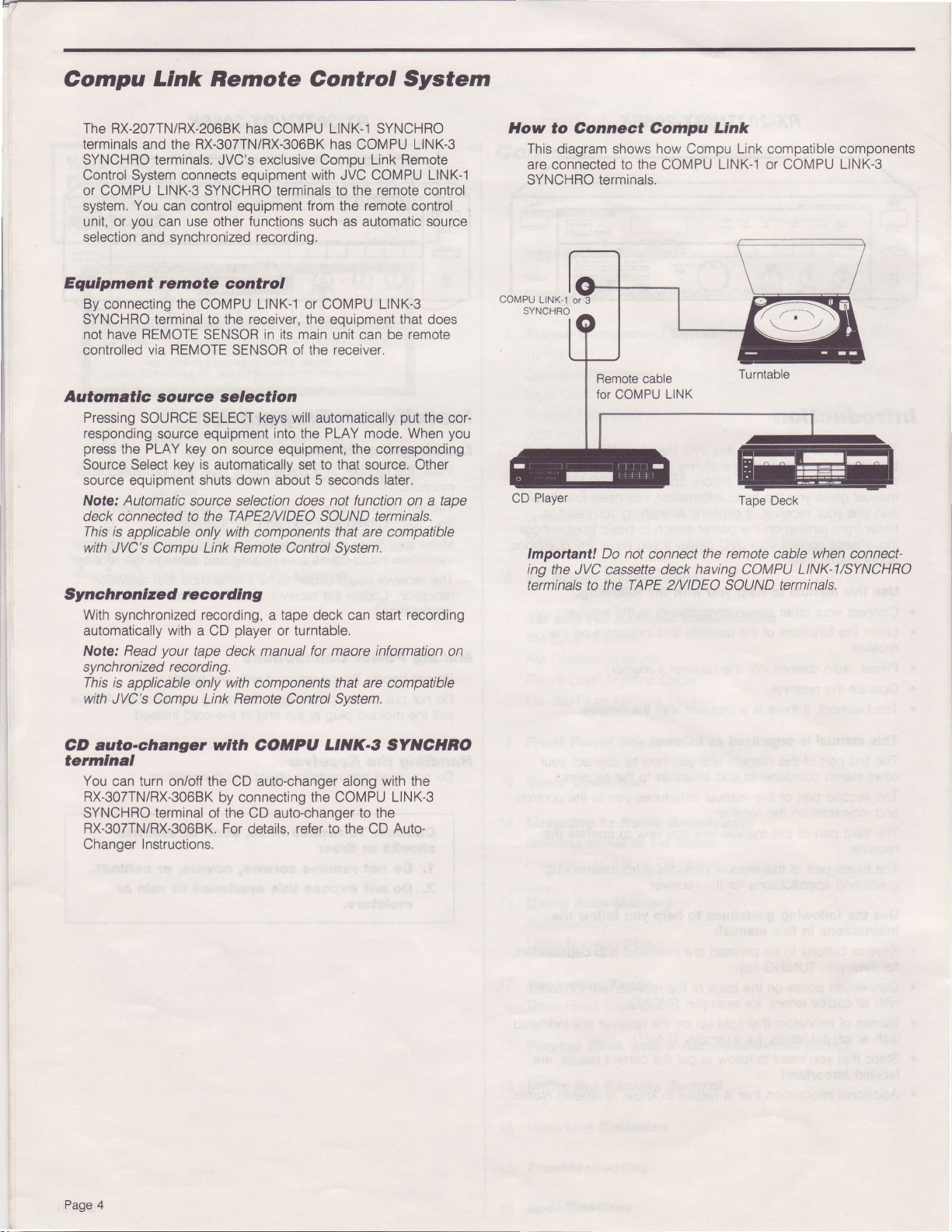
Compu
Link
Remote Control System
The RX-207TN/RX-2068K has
terminals
SYNCHRO terminals. JVC's exclusive Comou
Control System connects equipment
or COMPU
system. You can control
unit, or
selection and synchronized recording.
Equlpment remote
By connecting the
SYNCHRO terminal to the receiver, the equipment that does
have REMOTE
not
controlled via REMOTE SENSOR of the receiver.
Automatlc aource
Pressing
the RX-307TN/RX-306BK has
and
LINK-3
SYNCHRO terminals to the
you
can use other functions such as automatic source
control
COMPU
SENSOR in
aetectlon
SOURCE SELECT keys
COMPU LINK-1 SYNCHRO
COMPU
with
equipment
LINK-1 or COMPU LINK-3
from the remote control
its
main unit can be remote
Link Remote
JVC COMPU LINK-1
will automatically
LINK-3
remote
put
responding source equipment into the PLAY mode. When
press
Source Select
source equipment shuts down about 5 seconds
the
PLAY
key on source equipment, the corresponding
key is
automatically
set to that
source. Other
later.
Note: Automatic source selection does not function on a tape
deck connected to the TAPE2/VIDEO SOUND terminals.
This is
applicable only with components that are compatible
with
JVC's Compu
Link Remote
Control
System.
Synchronlzad recordlng
With
synchronized
automatically with a CD
Read
Note:
synchronized
This is
applicable only
with
JVC's Comou Link Remote Control Svstem.
recording, a tape
player
or turntable.
your
tape deck manual for maore
recordi ng.
with
components
deck can start
information
that are compatible
recording
control
the cor-
you
on
How
to Connect Compu
This
diagram
are connected to the COMPU
SYNCHRO terminals.
Player
CD
Important! Do not
ing
the JVC cassette deck
terminals to
shows how
connect
the TAPE 2/VIDEO SOUND terminals,
Link
Compu
Link
LINK-1
the remote cable
having
compatible
or COMPU
Tape Deck
COMPU
components
LINK-3
when
connect-
LINK-I/SYNCHRO
CD auto-changer
wlth
COHPU
LtNK-g
tetmlnal
You
RX-307TNiRX-3068K
turn on/off
can
the CD auto-changer along
by connecting the COMPU
SYNCHRO terminal of the CD auto-changer to the
RX-307TN/RX-306BK.
Changer
Instructions.
For details,
refer
to the CD
SYNCTIBO
with the
LINK-3
Auto-
Page 4
Page 5
Stereo
Component
Connections
You
can connect the following
your
of
r
Turntable
.
Compact Disc Player
.
Tape Deck(s)
r
VCR
The
components to the receiver.
lmporbnt!
stereo
receiver.
to the right
reverse the channels,
Turntable
Connect
Q
left
receiver.
lmpoftant!
moing magnetic
Compact DIsc Player
Connect the left
O
player
the receiver.
receiver:
or TV
following instructions will
Make sure
components to the left
Connect
the
and right
to the left
the right
jacks
on
the bottom row of the receiver. lf
left
and right channels
jacks
marked PHONO
Use the
receiver
(MM)
and right channels on
right
and
stereo components to the back
you
show
you
connect the left
jacks
channels of all stereo components
the stereo sound will be affected.
only with turntables
type cartridge.
jacks
how
on the
your
on
the
on
your
marked
to connect stereo
channels of all
top
row of the
turntable to
back of the
have
that
compact disc
the back
CD on
you
the
a
of
fape
O
@
Second
€)Connect
@Connect
VCB
{D Connect the left
@
Deck
Connect the left and right
REC)
marked OUT
Connect the
PLAY)
marked
REC)
2nlIDEO
the receiver.
PLAY)
SOUND
or
marked
Connect the left
or TV
marked
your
on
on
or TV
TV
to the left
to the left
tape
(REC)
left
and right
on the tape deck to the
(PLA[
lN
lape
the left
your
SOUND
the left
of the
lacks
OUT
(PLAY)
lN
on the back of the receiver.
Deck
and right
second tape
jacks
and right
tape deck to the left
marked lN
and right audio input
and right TAPE 2llIDEO
(REC)
and right audio
and
on the back
"Line
In" channels
deck to
the left
on the back of the receiver.
"Line
"Line
deck to the left
marked
"Line
(PLAY)
on the
back of the receiver.
right
TAPE 2llIDEO
and
Out" channels
left
and right
In"
channels
(REC)
OUT
Out" channels
and right TAPE
on the back of the receiver.
channels on
output channels
of the receiver.
(acks
right TAPE 1
TAPE 1
(acks
and
on the back of
SOUND
SOUND
marked
(acks
jacks
marked
right
TAPE
(acks
2//IDEO
your
jacks
your
on
jacks
jacks
marked
marked
VCR
VCR
Page 5
Page 6

r
I
i
Speaker
Connections
;WW
o
Soeakers 1
left
--
-IE
--rr-IIEIIE
t-.---r
rn,--:nr
rl!- -[rr
LU--.-r
E-.
-
EH
t//-U z/zGfl
fTrrn\t tTFrtYt
II||[ f,tr I.tE lta
right
--.-
vv
oo
@
Speakers 2
left right
B
o
(-).
is
ohms.
speakers
pair
and
(-)
and
and
(-)
and
pairs
of speakers
pairs
of speakers are called Speakers
match
the terminals
of
for
only
Check
have the
speakers
of
(-)
terminals of the right-side Speaker
terminals marked RIGHT on the
(-)
terminals of the
terminals marked LEFT on the
You
can connect two
this receiver. The two
and Speakers
Important!
nals with
(+)
and
Note: This
pedance
to make
Speaker
Wnen
O
€)
Speakers I
@
@
connecting speakers, open each terminal and
end of the speaker wire as shown.
the
Ctose
prace.
Connect
follows:
as
Connect
to
top
the
receiver.
Connect the
to the top
receiver.
2.
Be sure to
polarity
the
(-)
to
receiver
of 8 to 16
the
sure
fermlnals
terminals as shown to clamp the speaker
the first
(+)
the
(+)
(+)
(+)
polarity
the
with
use
your
correct
(Speakers
(four
speakers total) to
the speaker term|
of
the receiver.
on
speakers
speaker specifications
impedance.
1) to the receiver
left-side
(+)
having im-
insert
wires in
Speaker
1
to
the
1
1
AC
Page 6
Powet
o0
Connectlons
Speakets 2
lf
a second
connect them to the receiver as
@Connect
to the bottom
ranoirror
Connect the
@
to
the bottom
receiver.
tmpot|anil Before
make sure all stereo components are connected correctly.
Do not connect
watts
Gautlon. lo
ponont!
Plug the
volt. 60 Hz
You
nents to the two AC outlets on the back of the receiver.
Note: < RX-207TN/RX-2068K
pair
of speakers
(+)
the
(total)
power
can connect the
The
plugged
setting.
< RX.3O7TN/RX-3O6BK>
The AC
ON/STANDBY circuits. When the
STANDBY,
and
(+)
and
(+)
and
(+)
and
you
stereo
to the receiver.
prevent
otf bclore
cord
AC household
AC outlets
on
in,
regardless of the r*eiver's
outlets are connected to
power
(Speakers
(-)
terminals of the
(-)
terminals marked
(-)
terminals of the left-side Speaker 2
(-)
terminals
plug
the
components requiring more than 180
electrlc.hoclq tum dl rtcrso
you
Instlll or nemove
the
back
electrical outlet.
power
cords of the other stereo compo-
provide power'whenever
>
will not
2) is
follows.
right-side Speaker 2
marked LEFT
power
cord into an outlet,
of
receiver into a 120
the
the receiver's
power
be supplied.
to be used,
RIGHT
power
the
power
switch
on the
the
on
com-
cordl.
receiver is
switch
is
fo
set
Page 7

AM
and
FM Antenna
Connections
AM Loop Antenna
To receive radio broadcasts,
FM
antennas to the receiver.
An AM loop
FM
antennas use two types of cable connections:
cables
have a flat
antenna
have a round
connection.
is included with
coaxial connection while 300-ohm cables
you
will have to connect AM
AH Loop Antenna
Fold
Q
@
out the loop
Connect one antenna
on the receiver.
Connect the
@
terminal.
Note: These two terminals
the
speaker
Adjust
O
the
AM Outdoor Antenna
your
lf
AM broadcast reception
connect an
antenna.
lmportant! The
AM
broadcasts.
installing
Install
Q
tenna wire shold be about 16 to
Connect one end of the antenna
@
an outdoor antenna.
a single
marked AM EXT.
Note: Except for the
antenna
wire
Otherwise, the
from
the antenna base.
wire to
remaining
terminals.
loop
antenna as
AM
outdoor antenna
loop
AM
Do not
vinyl-covered
connection,
touches the
receiver
one of
antenna wire to the other AM LOOP
and
open
needed
is
unsatisfactory,
in
antenna
disconnect
must
the loop antenna when
antenna
40 feet
to the AM loop terminal
make
panel
rear
might
not
pick
and
your
receiver.
75-ohm
the AM LOOP terminals
the
close
get
to
the best reception.
addition
of the
to the
installed to receive
be
wire
outdoors.
(5
to
no uninsulated
sure
receiver.
way as
same
you
should
looo
The an-
12 meters) long.
up AM broadcasts.
75-Ohm Antenna
with
codial cable
Fl\,4 Feeder Antenna
F|t 75.Ohm Antenne
Loosen
Q
the screws
Cable
holding
the bracket to the
rear
the receiver.
Loosen the
O
the 300/75-ohm
cap of
terminal on
the rear
of the receiver.
Insert
@
the round antenna cable through the bracket from
below.
Vake
@
sure that the shield braid on the cable contacts the
bracket. and that the
center
conductor
of the cable contacts
the 300/75-ohm terminal.
lgfrten
@
the bracket screws and the cap on the 300/75-ohm
terminal.
Ft
?OO-Ohm
Loosen the cap on the 300/75-ohm terminal on the rear
Q
bf the receiver.
Loosen the cap on the 300-ohm terminal
O
Antenna
Cable
the rear
on
the receiver.
Connect the two conductors of the
@
antenna cable
300/75-ohm terminal and the 300-ohm terminal.
Tighten
@
Note: Whether
sure the antenna conductors do
on the receiver. This could cause
the caps on both terminals.
you
use the
75-ohm
not
poor
or 300-ohm cable, make
touch any other terminals
reception.
panel
panel
to the
of
panel
panel
of
Page 7
Page 8

Front Panel
RX-2O7TV/
<
RX.2O6BK>
-
-ffiRX.3O7TN/
<
RX-3O6BK>
Controls
< RX-2O7TN/
RX.2O6BK>
I
-<RX3O7TN/
RX.3O6BK>
ME
l-J
,,iffi.
Power
O
Press
switch again to turn
mooe.
Note: The receiver
the
the
@Speaker
Press
Speakers 2 on.
speakers off.
@Headphone.tack
Stereo
listening,
Source $elect
@
Use these six buttons to choose the stereo source
to listen
been selected.
TAPE 2NTDEO
9ource
G)
These live lights
played
may turn on
Swltch
this switch to turn
off the
uses a small amount of
STANDBY mode. To
power
cord.
on oower to the
power
disconnect
receiver. Press
and activate the
power (5
power
completely, unplug
Swltch
the two SPEAKERS switches
Press
the SPEAKERS switches out to turn the
headphones may
press
both speaker switches off.
Source Indicator
to.
be connected
in
to turn Soeakers 1 and
here. For
Lights show which source(s) have
PllONOt Press to listen to records.
Press to listen
CD;
FIG Press
Itl Press
to
to
1APE 1., Press to
to the TAPE 1
to CDs.
listen
to
listen
to
the
use
tape deck connected
jacks
SOUNDT Press to use the tape deck,
equalizer, or video
nected
jacks
TAPE
to the
on the receiver.
lndlcator Hghts
you
tell
which stereo source(s) are
through the receiver. The TAPE 2 MONITOR
independently
or off
while other indicators
the
STANDBY
watts)
private
you
want
FM
broadcasts.
AM
broadcasts.
on the receiver.
graphic
equipment con-
2llIDEO SOUND
being
indicaior
are
I
<RX-2o7TN/RX-2o6BK>
O
BECE YED Indlcator
This
indicator lights up when signals are received from the
remote
in
This indicator lights
control unit.
< RX.3O7TN/RX.3O6BK>
BECEMD
and POWER 9IANDBY
up when signals are
remote
control unit or when
the receiver is in the
lndlcator
received from the
STANDBY
mode.
9Remote
The Remote Sensor receives the signal sent by
Sensor
the remote
control unit.
lt is important
Note:
obstructions in order for
keep the Remote
to
it
receive
to
Sensor
signals
clear of
from the remote
control unit.
@Bass
This controls the
control
'
bass.
trcble Control
@
This controls the high-frequency sound
TREBLE
Control
right to
control
low-frequency
bass response. Turn
boost
right
to boost treble
range. Turn the BASS
sound
left to
range. Turn the
response.
decrease
Turn left
to
decrease treble.
@?alance
This controls the volume
speakers. Turn the BALANCE
for the right
increase volume for
left
and
@Volume
Turn
indicator lights
the remote control is
Control
balance between the
control right to
speaker(s).
right
speakers have
Turn
the BALANCE control left to
left
the
speake(s). ln the center
volume.
equal
Control and Yolume lndlcator
the VOLUME control to
up when the
used
adjust
power
is ON and fickers when
for VOLUME
the
volume.
and
left
and right
increase
position,
Hght
The
VOLUME
FADE
MUTING.
volume
Surround Indlcator Llghts
@
This indicator lights
Tuner DIspIay Wlndow
O
up when
the
The Tuner Display Window indicators
AM
and
FM
broadcast
reception.
is also used to set and recall oreset
8
Page
surround sWitch
provide
is
ON.
information on
The Tuner Display Window
radio
stations.
@funer
Use the buttons on the tuner to
cast station
for
setting and recalling
@9unound
This
you
want to listen to. These
Swltch
switch turns the
preset
surround sound effect ON or OFF.
in
the
AM
tune
buttons are also used
radio stations.
or
FM
broad-
Page 9

Basic
I
I
Operation
I
To
turn
O
The
Tuner
The
Source indicator
played.
Select
Q)
the speaker
SPEAKERS
switches.
your
on
Display
1
receiver,
Window
system
switch,
press
JVE
[J
"o
lights
Lights
show
you
the
want
SpEAKERS
the POWER
up.
the source
by
pressing
2
switch,
switch
that
was last
the
or both
on.
you
tt
O
@
()
want
Headphones
Note:
lf
press
both SPEAKERS
Press
one
source
The
corresponding
source
Note:
Operate
tape
deck)
Turn
the VOLUME
Impoftant!
a hearing
using
headphones,
sound.
to listen
Jack.
you
do not
of the
you
is
being
defect. Adjust
Source
want
to listen
played.
the
by following
Listening
through
want
headphones, plug
sound
switches
Select
coming
off.
buttons
to.
E
Source
stereo sources
control to
avoid
Indicator
the appropriate
adjust the
to
an ertremely
the volume
listening
through
to choose
Light
(for
example:
instruction
volume.
loud
properly.
to
an
ertremely loud
them
the
the
shows
which
CD,
manuals.
sound may
Especialty
in to
the
speakers,
stereo
stereo
phono,
cause
when
Note:
you press
and
heard.
lf
just
one
both
pair
of speakers
SPEAKERS
is
connected
switches,
no
to the
sound
receiver
will
be
turn
@
between
Turn
@
treble
Turn
@
bass
the BALANCE
the
left
and right
the TREBLE
(high
the BASS
(low
frequency)
control left
frequency)
control
left
control
speakers.
sound level.
left
or right
level.
sound
or right
or right to
to decrease
to
the
set
decrease
or increase
balance
Increase
or
Page
9
Page 10

Listening to
Radio
Broadcasts
ffi
.
t;:l
-- I t----1 |
L*lll
Selecting an
Turn
O
@
.
O
the
Press
the
you pressed
lf
appear
last AM frequency
the
you pressed
lf
appear in the
the last FM frequency
the TUNING key
Use
listen
to. Press the right side of the key to find higher frequen-
press
cies;
you
When
it
until
tunes a station in. You can stop auto{uning
Ing
any
The TUNED lndicator
oreciselv
AM
receiver
AM
or
the AM
in
Tuner
the
the FM
Tuner
the left
release
tuner
button.
to
either an AM or FM station.
FM
or
on
FM
Source Select button.
Display
Display Window. The recerver tunes in
side of
the
Station
Source Select button,
Window. The receiver
that was
Source Select button, FM and MHz
that was
to
TUNING key,
lights when the receiver is
played
played.
find
the
the key to
radio frequency
find
the
AM
frequencies.
lower
receiver
tuned
and
you
auto{unes
kHz
tunes
want to
press-
by
in
Press
@
station
improved, although
stereo) sound.
The STEREO
Presetting an AM or
Vnrrnan ^rocar . tntSl
memory.
number
tune to that station using the
TUNING key.
(See
Turn
Q
Press the AM
@
Use the TUNING key to tune
O
Dreset.
Press
@
The MEMORY indicator lights
blinks)
Using the Numeric keys, enter the channel
@
you
The channel number appears in the Tuner Display Window.
FM
the
MODE/MUTE button
with a weak or noisy signal. Reception wil be
you
indicator
and the
will be
FM
gf
preset
You
(1
to 40) Once a station
Using Numerrc Keys ' on
receiver
the
the MEMORY button.
in
the Tuner Display Window for about
want
to assrgn to the statron.
on.
or the
40 radiO StatiOnS
a station by assigning
FM
Source Select
when listening to an FM
listening
AUTO indicator
monaural
to
Station
intO
it
a channel
has
Numeric keys rather than the
page
in
the radio station
- -
and
preset, you
been
1.)
1
button,
CH appears
number
disaooear.
reCeiver'S
the
you
five
seconds.
(1
(non-
can
want to
-
(-
a0)
to
Note:
Tap the TUNING
quency
the
tAn thq ko\/ tn cpt lho f roar tanav nroaicaltt
lmportant! lf
lndicator doesn't light,
reception.
When
plays
are lighted.
P2^a 1n
tn
TUNING key down to change the frequency faster,
you
in stereo; the
of 10 kHzfor
steps
the
tune to
key momentarily to
AM and 0.1 MHzfor
receiver is
an FM station, the receiver
STEREO indicator and the AUTO indicator
tuned to a statton
try adjusting the
antenna
change
the fre-
FM.
then
the TUNED
but
for
better
automatically
Hold
lmportant! You must
MEMORY
soon,
Repeat
Note: Preset
long
plugged,
the
indrcator
press
the MEMORY button and start again.
the above
stattons are
as the receiver
presets
power
if
or
a
for
two or three days before erasrng
is
process
enter
lighted.
plugged
is
fatlure
the channel number while the
to
held in
indicator
lf the
preset
additional
receiver's memory as
the
in. lf
occurs, the
receiver is un-
the
receiver will keep
turns off too
radio
them.
stations.
Page 11

Using
Auto-Memory
Auto-Memory
The Auto-Memory function lets
preset
stations, and
the
memory. The receiver will scan
the stations, as they are
numbers.
(O
Turn the
Press the AM or the FM Source Select button.
@
Use
G)
start scanning
Press
@
receiver
on.
the TUNING key to
from.
AUTO MEMORY button.
the
The MEMORY indicator
in the Tuner Display Window
blinks)
Using the Numeric
@
(1
lmportant!
MEMORY indicator
soon,
When a radio station
indicator
frequency
about
starts again.
to 40)
press
five
you
You must
lights,
of
seconds.
keys,
want to
the AUTO MEMORY button and
the station tuned in are displayed alternately
assign
enter
is lighted. lf the indicator turns off too
is
tuned
and the
When this station
you
scan a serres of
ones
you
into the receiver's
want
radio frequencies and
tuned, with ascending channel
find
lights
lowest frequency
the
- -
and
for
lowest
the
enter
preset.
a
the channel
in,
scanning
preset
first
channel
is
radio
preset
you
want
five
seconds.
number
The
and
scanning
(-
TUNED
CH appears
about
channel
number while the
start again.
stops.
number
preset,
-
the
for
to
Uslng
Numerlc Keys
Preset stations are set
using the
To indicate
Numeric keys.
numbers 1 to 10,
indicate numbers
one other
key. See the
To indicate 17:
To indicate 20:
To indicate 25:
To indicate 40:
into the receiver's
to
40,
you
11
following examples:
press
the
+10
press
the +10
press
the +10 key twice,
press
10 key three times,
the +
memory and
press
the appropriate
need to use
then the
key,
key, then the
10 key
the +
7 key.
10 key.
then the 5
then the
recalled
key. To
and
key.
10 key.
you
lf
@
MEMORY button
are displayed
again.
This
filled or the upper
not want to
do
process
preset
that
station,
while the channel
alternately. The
continues automatically
frequency
number and
receiver will start
until all
limit is reached.
press
the
frequency
scanning
40 channels
AUTO
are
Page
11
Page 12

Hecording Tapes
you
lf
have a tape
2^/IDEO SOUND
stereo sources onto a taoe.
(OTurn
@
.
the receiver on,
Press the Source Select button for the source
record from.
Note: When recording from TAPE 2 to TAPE 1,
TAPE 2/VIDEO SOUND button and another button other than
TAPE 1.
Use the tape deck to record the source as it is
Follow
the instructions for
Note: Adjusting
affect the recording level. Follow the
deck.
deck connected
jacks
the
the receiver,
of
your
VOLUME
to the TAPE 1
tape deck,
control of
instructions
TAPE
you
the receiver will not
or
can record other
you
want to
press
playing.
your
for
the
tape
Playing Back with
a Surround-sound
Etfect
Playing back a stereo source with the SURROUND
produce
will
Connect speaker systems
@
terminals.
itffi
a surrounding sound effect.
to the
SPEAKERS
SPEIIGRS
un
1 and 2
key ON
Three.llead
you
lf
the
sound being recorded.
TAPE 2llIDEO
follows:
.
recording
Start
When the TAPE 2 MONITOR
the sound
Press the TAPE 2/VIDEO
MONITOR lndicator
the recording immediately
of
pressing
By
you
can compare the sound
quality
7ape Decks
have a three-head
SOUND
the source onto the
the source
of
TAPE
the
of the tape recording being made.
jacks
playing
Light will light. Now
2llIDEO SOUND
tape deck,
Connect
SOUND button. The TAPE 2
as
quality
you
can use
the tape deck to the
of the receiver and
TAPE
2 deck.
Indicator Light is off,
through the speakers.
you
it is made
button on and off,
of the source with the
hear the
the tape.
on
it
proceed
you
to monitor
as
hear
sound
Note: A
sound effect by
recommended
turn
@
Turn
O
Press
O
Play
@
lf
SPEAKERS
and
sound
Monaural source cannot be
sound effect.
single speaker system
itself,
for
a more
receiver
the
ON the SPEAKERS switches, 1 and
the SURROUND
back the stereo source.
a speaker system with a
pay
attention to
playback.
on.
2,
avoid using
produce
can
the use of two speaker sysfems
but
ideal
surrounding sound effect.
key.
low-rated
it independent of SPEAKERS
its VOLUME
played
input
control during
back
a surrounding
2.
is
connected
with the
is
to
1,
surrounding
surround
Page
12
Page 13

Using
the
Bemote
Control
Aim the signals at the REMOTE SENSOR
< RM-SR2O7U >
for
RX-2O7TN/RX-2068K
H3 14
EE]
>Pc
trl cl
EE
E]
FADE ruTIIS
EF
-
VOLUT'E +
SOURCE SELECT keys
Selectable Function keys
CONTROL Section
on the
receiver.
RM-SR3O7U
<
for RX'307TN/RX-3068K
PHOT€ CO
TAPE I
CfEE
FT' AM
>t a42
CfEEE
<6 >P
ll 5
EE EE
EE
vc? TAPE I CO oISC
Cf
FADEI'I.JTING
EE
>
tst3 a1
-
rxE5E I i
-VOLI.JI.IE+
.
.fYE
The remote
JVC's audio
Link Remote
Direct
control unit
gear
visual
Control System.
the transmitter window of the remote control unit at
**,0,1**Sil'ffi[
provided
from a remote
control
the receiver and
place
via the
target equipment within a distance of 7 meters.
avoid obstacles between the transmitter and
keys
slowly
positively,
and
making sure the desired
the target. Press
result.
The
key markings on the transmitter may
not match those
the equipment. Check the markings.
The remote control unit
they
not
do
support. Older equipment may not be
cannot
control
equipment
their input.
for
Check
LINK-3
SYNCHRO terminals on the remote equipment by a
remote
cable.
Switch
on
connection of
power
the
the
COMPU LINK-1 or COMPU
to all the equipment required before
starting operation.
When
operating the VCR by RM-SR307U, if the VCR has a
raemote control code switch, set the switch to
"A"
Compu
Take
care to
functions
functions
receptive
mode.
on
to
**,'L*Si€'SIil&
only)
change
to turn on or off the oower
the
POWER
O
(RM-SR307U
AUDIO: Press to
'
VCR: Press
TV:
VOLUME
€)
STANDBY.
Press
(-,
"fYE
to turn on or off
+)
Press to adjust the output sound
FADE MUTING
Press to decrease the output sound
power
for the receiver ON or
the
oower to JVC's
level.
gradually.
level
to JVC's VCR.
receiver.
W
Page 13
Page 14

Operating the source equipment
FM/AM
1 . Pr"r.
2. Ur" the Selectable
broadcast
FM
the
or AM key of the
Function
keys.
SOURCE
PRESET
+ : Scans to higher
-
:
Scans to
preset
lower
oreset channels.
channels.
Turntable
1 . Pr"r. the PHONO key
2. U." the Selectable
CD
r
Player
:
Stop
play.
1 . Pr"., the CD key of the
of the SOURCE SELECT keys.
Function
kevs.
SOURCE
2. U." the Selectable Function keys.
: Stops operation.
I
:
Skips to the beginning of the
11<
:
Skips to the beginning of the next track,
)1't
:
Moves backward
<<
: Moves forward
>>
: Stops
1
play
quickly
quickly
during
temporarily. To release it,
CD Auto-changer
1 . Pr".. the
DISC key
CD
of the CONTROL Section keys.
2. U.. the Selectable Function keys.
P:
1-5,
Pr"., the
3.
4.
U." the Selectable Function kevs.
t
K<
>x
<<
)}
tl
Select the disc number.
key of
CD
Starts
the SOURCE SELECT
play.
Stops operation.
Skips to the
Skips to the
Moves backward
Moves forward
Stops
beginning of
beginning of the
quickly
quickly
play
temporarily. To release it,
during
SELECT keys.
SELECT r<eys.
previous
during
track.
play.
play,
press
xeys.
previous
the
next
during
track.
track.
play.
play.
press
Tape Deck
1 . Pr"., the TAPE 1 kev
2.
(TAPE
1)
the
of
Section
U."
keys.
the
: Stops operation.
r
Selectable
Function keys.
SOURCE SELECT
r<< : Skips to the beginning of the
:
Skips to the beginning of the
>rr
:
u
: Fast winds the tape from right to
<<
playback/recording
Stops
To release it,
press
)
.
previous
next
tune.
temporarily.
left.
or
CONTROL
tune.
p : Fast winds the tape from left to right.
: Press together with ) to start recording.
c
Press together with
.
Use CONfROL Section keys
equipment
source,
playing
Tape Deck
for
a CD.
(TAPE
you
while
are
example, to
2)
1 . Pr"r, the TAPE 2 key ot the SOURCE
2. nt^p"deck
cannot
connected to
be
operated
with the remote
lt
to enter record-pause
(VCR
listening to
have
or TAPE
the sound of another
a tape deck standby
the TAPE 2/VIDEO
control unit. Use
1)to
operate an
while
SELECT
keys.
SOUND terminal
the
mode.
switches
or buttons on the apparatus.
)
(RM-SR307U
VCR
o
Aim
the signals directly at the
a
| . Press the
2. U.. the Selectable Function keys,
I
1
<<
>>
.
only)
VCR
key of the CONTROL
: Stops operation.
: Stops
: Rewinds
: Fast-forwards
: Press
playbacl</recording
pause/still
the
together
Press together with
mooe.
mode. To
video tape.
video tape.
with
VCR.
Section
temporarily and
release
)
to start
n
to enter record-standby
Keys.
press
it,
recording.
enters
)
.
)
Page
14
Page 15

Inserting
Battefies
Troubleshooting
Batteriee
The Remote Control
1.5V)
batteries.
The use of
Battery
long-life
Beplacement
unit uses
dry cells
(2)
two
AAA size
is
recommended.
lf the range of the remote seems shortened, the batteries may
be old.
Use batteries of the same brand.
even though they
lf
extended
1.
Remove the rear cover
down
Try replacing
lmportant! Do not
you
are not
Cauilont
of them
gently
planning
period
of time, remove the
Do not heat
by bumlng.
while
the old batteries.
use a new battery
with
Batteries
look
alike.
to use the remote control for an
batteries.
or attempt to dlspose
remote control unit by
of the
sliding
batteilea
it
out.
(UM-4,
an old battery.
can vary
in
pressing
R03
voltage
Problem
Receiver
play;
Indicators
light up.
No sound from the
^^ ^ ^t. ^-^
Sound
speaKer onry.
Continuous hiss or
buzzing during
reception.
does
from
not
do
one
FM
PosslbleCauee Solutions
Power cord
plugged
not
Speaker
connected
Speaker Buttons
correctly. Buttons
set
Speaker wires
connected
Balance Control may
be set
extreme.
Incoming signal may Adjust antenna.
be too
Incorrect antenna
used.
not
in.
wires not
properly.
not
properly.
not
Plug
an
Check speaker
Reconnect
Press the Speaker
desired.
Check speaker
Reconnect
Slide Balance Control
to one so both
have sound.
weak.
Station
away
Check with
er to make sure
are using the correct
type of antenna.
Power cord into
AC
outlet.
wiring
if needed.
in
or out as
wiring
if needed.
speakers
may
too far
be
to receive.
your
deal-
you
lnsert the batteries, making sure that their
2.
that of the diaoram inside the remote.
Replace
3.
the
rear
cover
position
matches
Occasional
noise
reception.
Loud
record
Howling during record
playrng.
cracking
during
hum
during
playing.
FM
Antenna not
connected
lgnition noise from
automobiles.
Turntable not Check
connected
lnterference
other electrical
applrances.
Turntable too close to
a speaKer.
properly.
properly.
from
Make sure all
anrennas are
connected.
Move the antenna
further away
road.
manual. Ground the
turntable if reouired,
Try moving the
cord or
a different outlet.
Move
from the turntable.
propeny
from
the
the turntable
power
plugging
speakers away
into
Page 15
Page 16

RX-207TN/RX-2068K
Specific
ations
RX-307TN/RX-3068K
40 watts
channels driven
20 k1z, with no more
harmonic
per
distortion.
('66
70dB
Mono: 10.8
Mono: 16.3
Stereo: 38.3 dBf
30
channel, min. RMS,
lnto
8 ohms from 40 Hz
rHF), 78dB
('66
91dB
87.5 MHz
Hz
15
to
both
than 0.080/o total
0.080/o
2.5 mV/47k
200 mV/47k ohms
20 Nz Io 20 kHz + 1dB
(',78
rHF
rHF),
80dB
to
(0.95p
dBf
(1,8p
dBf
(22.5p
Mono:
Stereo:
Mono: 0.150/o
Stereo: 0.20lo
kHz, +0.5 dB,
60 dB,
(at
85
dB
40
dB
to
40 watts
at
ohms
200 mV
REC OUT)
(',78
tHF)
108.0
MHz
V/75 ohms)
V/75 ohms)
V/75 ohms)
80 dB
73
dB
-3
dB
1.5
dB
+400kHz
98
MHz)
(at
1 kHz)
Output Power
(CD
in
Speakers out)
Intermodulation
Input
Sensitivity/lmpedance
TAPE 1 PLAY,
Recording
Frequency
CD, TAPE 1,
Signal{o-Noise Ratio
TAPE 1, TAPE
CD,
Tuning Range
Usable Sensitivity
50dB
Quieting
Signal{o-Noise Ratio
Total
Harmonic Distortion
(1
Frequency Response
Capture
Alternate
Ratio
Channel Selectivity
lF Response Ratio
Stereo Separation
Distortion
PHONO
TAPE 2 PLAY,
Output Level
Response
PHONO
kHz)
2
TAPE
2
Sensitivity
(85
dBf)
CD
80 watts
channels
20
harmonic
0.030/o at 80 watts
2.5 mV/47k ohms
200 mV/47k
200 mV
20 Hz to 20 kHz
70dB
eldB
87.5 MHz to 108.0
Mono: 10.8
Mono: 16.3
Stereo: 38.3 dBf
Mono: 80
Stereo:
Mono: 0.150/o
Stereo: 0.20lo
30 Hz to 15 kHz, +0.5 dB,
1.5
60
85 dB
40 dB
per
driven
kHz,
with no more
distortion.
('66
('66
73
dB
+400kHz
dB,
(at
98 MHz)
(at
channel, min. RMS, both
into
8
ohms
than 0.030/o total
ohms
+1dB
IHF),
rHF), 80dB
dBf
dBf
dB
dB
1
kHz)
('78
78dB
('78
MHz
(0.95p
(1.8p
V/75 ohms)
(22.5p
rHF REC OUT)
rHF)
V/75 ohms)
V/75 ohms)
from 40
-3
dB
Hz
to
sIk
F€
EN
30p V.
(loop
25 dB
1,710
(external)
antenna)
(100mV/m)
(t
10 kHz)
60 Hz
530 kHz to
300p V/m.
50 dB
AC 12OV'v,
120 watts, 150VA
17-3116 x 5 x 13 inches
(435
x
126 x 330 mm)
14.8 lbs.
(6.7
kHz
kg)
Tuning
Signallo-Noise Ratio
Power
Power
Range
Sensitivity
Selectivity
Requirements
Consumption
Dimensions
(WidthxHeightxDepth)
Weight
-Measured
Design
and specifications
JVE
VICTOR
COTIPANY
OFJAPAN, LIMITED
530 kHz to 1,710 kHz
(external)
V.
30p
300p V/m.
50
25 dB
AC
190
17-3116
(435
18.3 lbs
1,000
at
dB
120V'v,
(loop
(100mV/m)
(t
10 kHz)
watts,,
260VA
x 5 x 13 inches
x 126 x
(8.3
i
kHz.
subject to change without notice.
antenna)
60 Hz
330 mm)
ks)
@
tos''*tt
s42rM
 Loading...