

Page 1
SERVICE MANUAL
LCD INTEGRATED DIGITAL TV
YA206B20054
BASIC CHASSIS
LT-32D50BJ,
LT-32D50SJ
Supplementary
Please be informed that this service manual contains the related matters following the parts replacement in
the LCD PANEL UNIT.
For details other than those described in this manual, please refer to the LT-32D50BJ and LT-32D50SJ
service manual (No.YA206, 2005/1).
FL
SECTION 1
PRECAUTION
Please refer to "LT-32D50BJ and LT-32D50SJ (No.YA206)" about this section.
SECTION 2
SPECIFIC SERVICE INSTRUCTIONS
Please refer to "LT-32D50BJ and LT-32D50SJ (No.YA206)" about this section.
COPYRIGHT © 2005 Victor Company of Japan, Limited
No.YA206B
2005/4
Page 2
SECTION 3
DISASSEMBLY
CAUTION AT DISASSEMBLY:
• Make sure that the power cord is disconnected from the outlet.
• Pay special attention not to break or damage the parts.
• When removing each board, remove the connectors as required. Taking notes of the connecting points (connector numbers)
makes service procedure manageable.
• During the procedure, place a mirror mat etc. under the LCD UNIT and be careful not to damage the PANEL.
• Make sure that there is no bent or stain on the connectors before inserting, and firmly insert the connectors.
3.1 DISASSEMBLY PROCEDURE
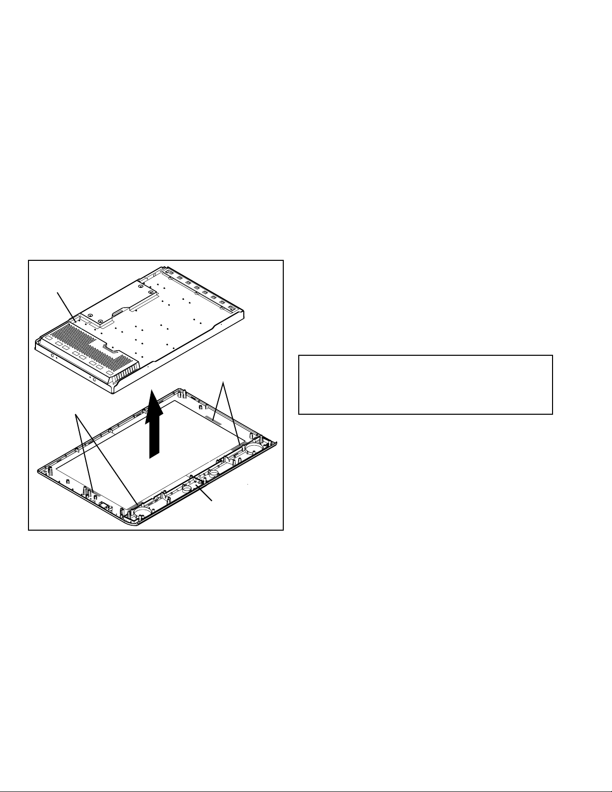
3.1.1 CAUTION ON REMOVING THE LCD PANEL UNIT
The LCD PANEL is fixed to the FRONT PANEL (at the back side)
by using double-side adhesive tapes. To remove the LCD
PANEL UNIT, remove the adhesive tape on the FRONT PANEL
slowly.
LCD PANEL UNIT
Double-side adhesive tapes
Double-side adhesive tapes
FRONT PANEL
3.1.2 REMOVING THE CONTROL PWB (Fig.1)
• Remove the STAND.
• Remove the REAR COVER.
• Remove the LCD PANEL UNIT.
(1) Remove the 4 screws [A], then remove the CONTROL
PWB COVER.
(2) Remove the 2 screws [B], then remove the CONTROL
PWB.
CAUTION:
Carry out the procedure with extra care as the FERRITE
CORE is affixed with double-side adhesive tapes and it may
break if extra force is applied.
3.1.3 REMOVING THE INVERTER PWB (Fig.1)
• Remove the STAND.
• Remove the REAR COVER.
• Remove the LCD PANEL UNIT.
(1) Remove the 6 screws [C], then remove the INVERTER
PWB COVER.
(2) Remove the 3 screws [D], then remove the INVERTER
PWB.
(3) Remove the 8 screws [E], then remove the INVERTER
PWB COVER.
(4) Remove the 3 screws [F], then remove the INVERTER
COLD PWB.
3.1.4 REMOVING THE BACK LIGHT UINT (Fig.1)
CAUTION:
When replacing the BACK LIGHT UINT, be careful to
prevent dust attachment to the UNIT. If dust particles
attached to the UNIT, it becomes the cause of uneven
brightness.
• Remove the STAND.
• Remove the REAR COVER.
• Remove the LCD PANEL UNIT.
• Remove the CONTROL PWB.
• Remove the INVERTER PWB.
• Remove the INVERTER COLD PWB.
(1) Remove the 14 screws [G], then remove the TOP PANEL
FRAME.
(2) Remove the 4 screws [H], then remove the LCD PANEL.
CAUTION:
When removing the LCD PANEL, be careful not to give
stress to the FPC which connects the PWB and the LCD
PANEL.
CAUTION ON EXCHAGING THE BACK LIGHT UINT
• If the screws that are not specified in this section are
removed, the LCD PANEL will be removed and it cannot be
reassembled.
1-2 (No.YA206B)
Page 3

INVERTER PWB COVER
C
D
INVERTER PWB
A
FERRITE CORE
B
CONTROL PWB
COVER
CONTROL PWB
INVERTER COLD PWB
E
F
FRONT
LCD PANEL UNIT
TOP PANEL FRAME
FRONT
G
LCD PANEL
H
Fig.1
BACK LIGHT UNIT
(No.YA206B)1-3
Page 4

SECTION 4
ADJUSTMENT
Please refer to "LT-32D50BJ and LT-32D50SJ (No.YA206)" about this section.
SECTION 5
TROUBLESHOOTING
Please refer to "LT-32D50BJ and LT-32D50SJ (No.YA206)" about this section.
1-4 (No.YA206B)
Page 5

PARTS LIST
EXPLODED VIEW
INVERTER PWB COVER
151
FERRITE CORE
CONTROL PWB
COVER
150
152
FRONT
LCD PANEL UNIT
TOP PANEL FRAME
FRONT
LCD PANEL
153
EXPLODED VIEW PARTS LIST
Ref.No. Part No. Part Name Description Local
150 LJ94-00414B CONTOROL PWB
151 LJ97-00329A INVERTER PWB
152 LJ97-00378A INVERTER COLD PWB
153 LJ96-01030A BACK LIGHT UNIT
(No.YA206B)1-5
Page 6

Victor Company of Japan, Limited
AV & MULTIMEDIA COMPANY DISPLAY CATEGORY 12, 3-chome, Moriya-cho, Kanagawa-ku, Yokohama-city, Kanagawa-prefecture, 221-8528, Japan
(No.YA206B)
Printed in Japan
VPT
 Loading...