

Page 1
SERVICE MANUAL
LCD PANEL TELEVISION
YA30320058
LT-20B60SU,
LT-20B60SJ
TABLE OF CONTENTS
1 PRECAUTION. . . . . . . . . . . . . . . . . . . . . . . . . . . . . . . . . . . . . . . . . . . . . . . . . . . . . . . . . . . . . . . . . . . . . . . . . 1-3
2 SPECIFIC SERVICE INSTRUCTIONS . . . . . . . . . . . . . . . . . . . . . . . . . . . . . . . . . . . . . . . . . . . . . . . . . . . . . . 1-7
3 DISASSEMBLY . . . . . . . . . . . . . . . . . . . . . . . . . . . . . . . . . . . . . . . . . . . . . . . . . . . . . . . . . . . . . . . . . . . . . . 1-10
4 ADJUSTMENT . . . . . . . . . . . . . . . . . . . . . . . . . . . . . . . . . . . . . . . . . . . . . . . . . . . . . . . . . . . . . . . . . . . . . . . 1-14
5 TROUBLESHOOTING . . . . . . . . . . . . . . . . . . . . . . . . . . . . . . . . . . . . . . . . . . . . . . . . . . . . . . . . . . . . . . . . . 1-14
COPYRIGHT © 2005 Victor Company of Japan, Limited
No.YA303
2005/8
Page 2

If you need more information on Computer and Electronic Repair, please visit these
in fact
websites to improve yourself.
http://www.fastrepairguide.com
http://www.protech2u.com
http://www.plasma-television-repair.com
http://www.lcd-television-repair.com
Happy Repairing!!
Highly Recommended Repair Ebook:
If you’re a LCD Monitor repairer, then this is the best guide for you.
Why? Because, the author revealed all his LCD Monitor Repairing
secrets for you. I think, with just few Repair tips you learned from
this guide you will get back your investment!
Click Here to read more.
This eBook will show you how to test the electronic component
correctly and accurately. Some of you may say that I don’t
need this eBook because it is too simple! Do you know that,
there is lots of testing electronic components secrets I have learned
from this guide? Do you know how to test a‘TRIAC’ correctly and
accurately? If you answer no then I guess you have to get this
EBook. Click Here to read more.
Are you tired of searching the service manuals to look for the value
of a burnt resistor? If the answer is YES, then this eBook is a ‘must
have’ guide for you. You can save a lot of time and be able to repair
customer’s Electronic equipment with burnt resistors in it.
Click here to read more.
Page 3
SPECIFICATION
Items Contents
Dimensions ( W × H × D ) 64.4cm × 48.1cm × 20.0cm [Included stand]
64.4cm × 41.6cm × 8.8cm [TV only]
Mass 8.9kg [Included stand]
7.4kg [TV only]
Power Input DC12V (TV)
AC220 ~ 240V 50Hz (Adaptor)
Power Consumption 50W (Standby: 3.0W)
TV RF System CCIR (B/G, DK, I, L)
Colour System PAL / SECAM / NTSC 3.58/4.43 [EXT only]
Stereo System A2 (B/G) / NICAM (B/G, I, L)
Receiving Frequency VHF
Intermediate
Frequency
Colour Sub
Carrier Frequency
Teletext System FLOF (Fastext level 2.5), WST(World Standard system)
LCD panel 20V-inch (4 : 3)
Screen Size Diagonal : 51.1cm (H : 41.1cm × V : 30.95cm)
Display Pixels Horizontal : 800 dots × Vertical : 600 dots
Audio Power Output 5W + 5W(10% THD)
Speaker 3.3cm × 14.5cm × 2
Aerial terminal (VHF/UHF) F-type connector, 75Ω unbalanced, coaxial
EXT-1 / EXT-2 (Input / Output) 21-pin Euro connector (SCART socket ) × 2
EXT-3 (Input) S-Video
PC (RGB) Input D-sub 15pin × 1
PC AUDIO input 3.5mm stereo mini jack × 1
Audio output 500mV (rms), Low impedance, RCA pin jack × 2
Headphone 3.5mm stereo mini jack × 1
Remote Control Unit RM-C1861 (AA/R6 dry cell battery × 2)
SECAM
47 MHz - 470 MHz
UHF
470 MHz - 862 MHz
CATV
S1 - S20 / S21 - S41
VIF
38.9 MHz (B/G, I, L)
SIF
33.4 MHz (5.5MHz : B/G)
32.9 MHz (6.0MHz : I)
32.4 MHz (6.5MHz : L)
PAL
4.43 MHz
4.40625 MHz / 4.25MHz
NTSC
3.58 MHz / 4.43 MHz
TOP (German system)
Mini-DIN 4 pin × 1
Y: 1V (p-p), Positive (Negative sync provided), 75 Ω
C: 0.286V (p-p) (Burst signal), 75 Ω
Video
1V (p-p), Positive (Negative sync provided), 75 Ω, RCA pin jack × 1
Audio
500mV (rms), High impedance, RCA pin jack × 2
R/G/B : 0.7V (p-p), 75Ω
HD / VD : 1V (p-p) to 5V (p-p), high impedance
< Available signal >
VGA : 640 pixels × 480 pixels (Horizontal : 31.5kHz / Vertical : 60Hz)
XGA : 1024 pixels × 768 pixels (Horizontal : 48.4kHz / Vertical : 60Hz)
Design & specifications are subject to change without notice.
1-2 (No.YA303)
Page 4

SECTION 1
PRECAUTION
1.1 SAFETY PRECAUTIONS [EXCEPT FOR UK]
(1) The design of this product contains special hardware,
many circuits and components specially for safety
purposes. For continued protection, no changes should be
made to the original design unless authorized in writing by
the manufacturer. Replacement parts must be identical to
those used in the original circuits. Service should be
performed by qualified personnel only.
(2) Alterations of the design or circuitry of the products should
not be made. Any design alterations or additions will void
the manufacturer's warranty and will further relieve the
manufacturer of responsibility for personal injury or
property damage resulting therefrom.
(3) Many electrical and mechanical parts in the products have
special safety-related characteristics. These
characteristics are often not evident from visual inspection
nor can the protection afforded by them necessarily be
obtained by using replacement components rated for
higher voltage, wattage, etc. Replacement parts which
have these special safety characteristics are identified in
the parts list of Service manual. Electrical components
having such features are identified by shading on the
schematics and by ( ) on the parts list in Service
manual. The use of a substitute replacement which does
not have the same safety characteristics as the
recommended replacement part shown in the parts list of
Service manual may cause shock, fire, or other hazards.
(4) Don't short between the LIVE side ground and
ISOLATED (NEUTRAL) side ground or EARTH side
ground when repairing.
Some model's power circuit is partly different in the GND.
The difference of the GND is shown by the LIVE : ( ) side
GND, the ISOLATED (NEUTRAL) : ( ) side GND and
EARTH : ( ) side GND.
Don't short between the LIVE side GND and ISOLATED
(NEUTRAL) side GND or EARTH side GND and never
measure the LIVE side GND and ISOLATED (NEUTRAL)
side GND or EARTH side GND at the same time with a
measuring apparatus (oscilloscope etc.). If above note will
not be kept, a fuse or any parts will be broken.
(5) When service is required, observe the original lead dress.
Extra precaution should be given to assure correct lead
dress in the high voltage circuit area. Where a short circuit
has occurred, those components that indicate evidence of
overheating should be replaced. Always use the
manufacturer's replacement components.
(6) Isolation Check (Safety for Electrical Shock Hazard)
After re-assembling the product, always perform an
isolation check on the exposed metal parts of the cabinet
(antenna terminals, video/audio input and output terminals,
Control knobs, metal cabinet, screw heads, earphone jack,
control shafts, etc.) to be sure the product is safe to operate
without danger of electrical shock.
a) Dielectric Strength Test
The isolation between the AC primary circuit and all metal
parts exposed to the user, particularly any exposed metal
part having a return path to the chassis should withstand a
voltage of 3000V AC (r.m.s.) for a period of one second. (.
. . . Withstand a voltage of 1100V AC (r.m.s.) to an
appliance rated up to 120V, and 3000V AC (r.m.s.) to an
appliance rated 200V or more, for a period of one second.)
This method of test requires a test equipment not generally
found in the service trade.
b) Leakage Current Check
Plug the AC line cord directly into the AC outlet (do not use
a line isolation transformer during this check.). Using a
"Leakage Current Tester", measure the leakage current
from each exposed metal part of the cabinet, particularly
any exposed metal part having a return path to the chassis,
to a known good earth ground (water pipe, etc.). Any
leakage current must not exceed 0.5mA AC (r.m.s.).
However, in tropical area, this must not exceed 0.2mA AC
(r.m.s.).
Alternate Check Method
Plug the AC line cord directly into the AC outlet (do not
use a line isolation transformer during this check.). Use
an AC voltmeter having 1000Ω per volt or more
sensitivity in the following manner. Connect a 1500Ω
10W resistor paralleled by a 0.15µF AC-type capacitor
between an exposed metal part and a known good earth
ground (water pipe, etc.). Measure the AC voltage
across the resistor with the AC voltmeter. Move the
resistor connection to each exposed metal part,
particularly any exposed metal part having a return path
to the chassis, and measure the AC voltage across the
resistor. Now, reverse the plug in the AC outlet and
repeat each measurement. Any voltage measured must
not exceed 0.75V AC (r.m.s.). This corresponds to
0.5mA AC (r.m.s.).
However, in tropical area, this must not exceed 0.3V AC
(r.m.s.). This corresponds to 0.2mA AC (r.m.s.).
AC VOLTMETER
(HAVING 1000 /V,
OR MORE SENSITIVITY)
0.15 F AC-TYPE
GOOD EARTH GROUND
1500 10W
PLACE THIS PROBE
ON EACH EXPOSED
ME TAL PAR T
(No.YA303)1-3
Page 5

1.2 SAFETY PRECAUTIONS [FOR UK]
(1) The design of this product contains special hardware and many circuits and components specially for safety purposes. For
continued protection, no changes should be made to the original design unless authorized in writing by the manufacturer.
Replacement parts must be identical to those used in the original circuits. Service should be performed by qualified personnel
only.
(2) Alterations of the design or circuitry of the product should not be made. Any design alterations or additions will void the
manufacturer's warranty and will further relieve the manufacturer of responsibility for personal injury or property damage
resulting therefrom.
(3) Many electrical and mechanical parts in the product have special safety-related characteristics. These characteristics are often
not evident from visual inspection nor can the protection afforded by them necessary be obtained by using replacement
components rated for higher voltage, wattage, etc. Replacement parts which have these special safety characteristics are
identified in the Parts List of Service Manual. Electrical components having such features are identified by shading on the
schematics and by ( ) on the Parts List in the Service Manual. The use of a substitute replacement which does not have the
same safety characteristics as the recommended replacement part shown in the Parts List of Service Manual may cause shock,
fire, or other hazards.
(4) The leads in the products are routed and dressed with ties, clamps, tubing’s, barriers and the like to be separated from live parts,
high temperature parts, moving parts and / or sharp edges for the prevention of electric shock and fire hazard. When service is
required, the original lead routing and dress should be observed, and it should be confirmed that they have been returned to
normal, after re-assembling.
WARNING
(1) The equipment has been designed and manufactured to meet international safety standards.
(2) It is the legal responsibility of the repairer to ensure that these safety standards are maintained.
(3) Repairs must be made in accordance with the relevant safety standards.
(4) It is essential that safety critical components are replaced by approved parts.
(5) If mains voltage selector is provided, check setting for local voltage.
1-4 (No.YA303)
Page 6
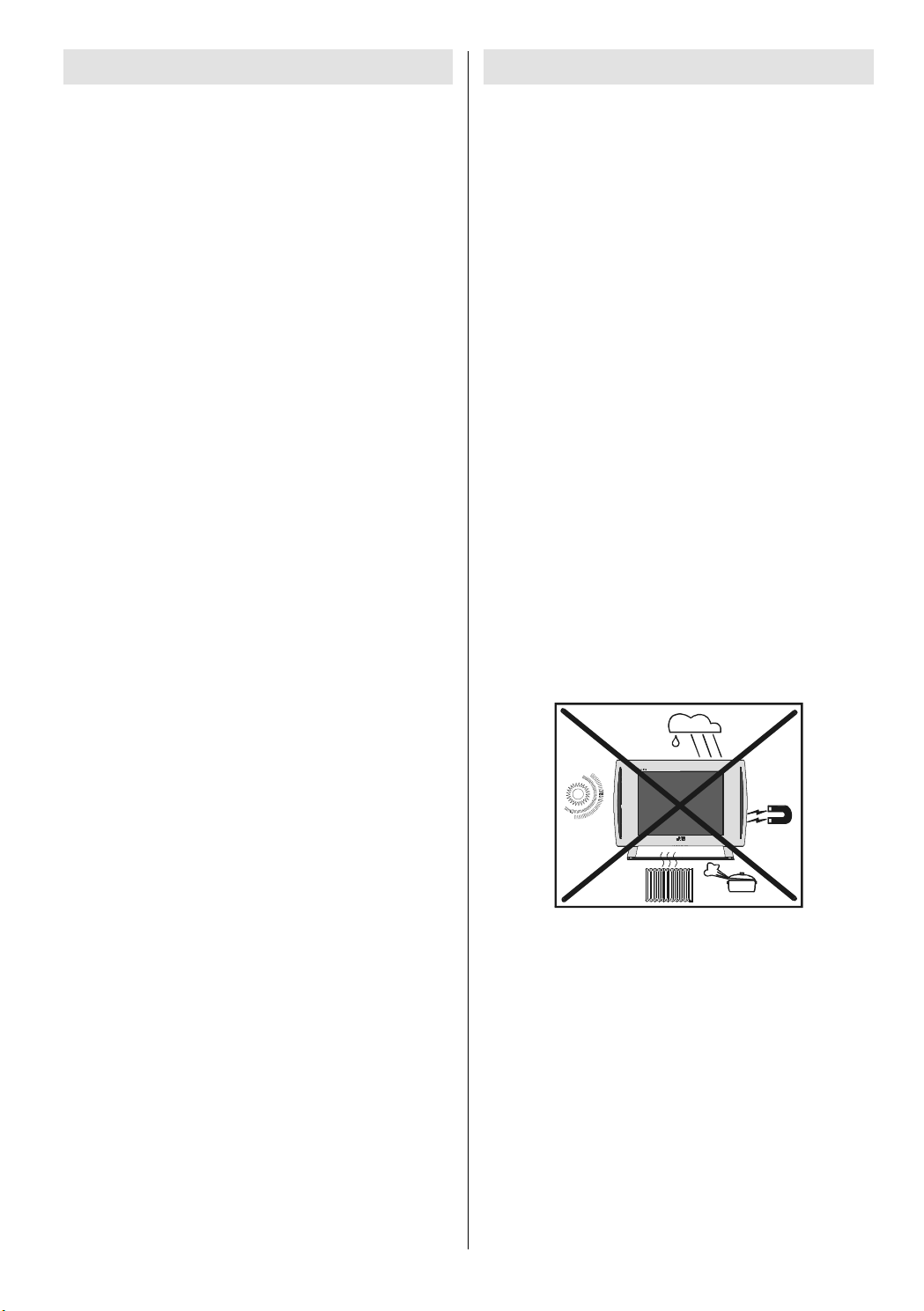
1.3 INSTALLATION
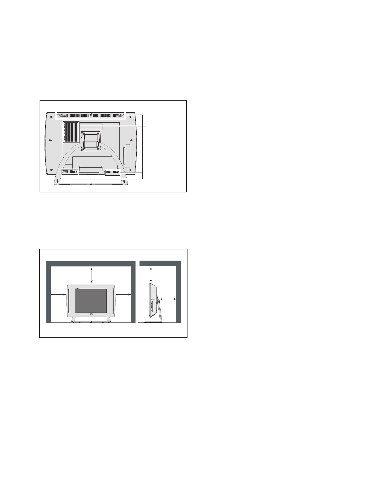
1.3.1 HEAT DISSIPATION
If the heat dissipation vent behind this unit is blocked, cooling
efficiency may deteriorate and temperature inside the unit will
rise. The temperature sensor that protects the unit will be
activated when internal temperature exceeds the pre-determined
level and power will be turned off automatically.Therefore,
please make sure pay attention not to block the heat dissipation
vent as well as the ventilation outlet behind the unit and ensure
that there is room for ventilation around it.
Ventilation hole
1.3.2 INSTALLATION REQUIREMENTS
Ensure that the minimal distance is maintained, as specified
below, between the unit with and the surrounding walls, as well
as the floor etc.Install the unit on stable flooring or stands.Take
precautionary measures to prevent the unit from tipping in order
to protect against accidents and earthquakes.
1.3.3 NOTES ON HANDLING
(1) WHEN TAKING UNIT OUT OF A PACKING CASE
When taking the unit out of a packing case, do not grasp
the upper part of the unit. If you take the unit out while
grasping the upper part, the LCD PANEL may be damaged
because of a pressure. Instead of grasping the upper part,
put your hands on the lower backside or sides of the unit.
(2) AS FOR PRESSING OR TOUCHING A SPEAKER
Be careful not to press the opening of the speaker in the
side part of the unit and around them since the decorative
sheet on the surface of the openings may be deformed.
100 mm
100 mm
*Diagram differs from actual appearance.
100 mm
100 mm
50 mm
(No.YA303)1-5
Page 7

1.4 HANDLING LCD PANEL
1.4.1 PRECAUTIONS FOR TRANSPORTATION
When transporting the unit, pressure exerted on the internal LCD
panel due to improper handling (such as tossing and dropping)
may cause damages even when the unit is carefully packed. To
prevent accidents from occurring during transportation, pay
careful attention before delivery, such as through explaining the
handling instructions to transporters.
Ensure that the following requirements are met during
transportation, as the LCD panel of this unit is made of glass and
therefore fragile:
(1) USE A SPECIAL PACKING CASE FOR THE LCD PANEL
When transporting the LCD panel of the unit, use a special
packing case (packing materials). A special packing case
is used when a LCD panel is supplied as a service spare
part.
(2) ATTACH PROTECTION SHEET TO THE FRONT
Since the front (display part) of the panel is vulnerable,
attach the protection sheet to the front of the LCD panel
before transportation. Protection sheet is used when a LCD
panel is supplied as a service spare part.
(3) AVOID VIBRATIONS AND IMPACTS
The unit may be broken if it is toppled sideways even when
properly packed. Continuous vibration may shift the gap of
the panel, and the unit may not be able to display images
properly. Ensure that the unit is carried by at least 2
persons and pay careful attention not to exert any vibration
or impact on it.
(4) DO NOT PLACE EQUIPMENT HORIZONTALLY
Ensure that it is placed upright and not horizontally during
transportation and storage as the LCD panel is very
vulnerable to lateral impacts and may break. During
transportation, ensure that the unit is loaded along the
traveling direction of the vehicle, and avoid stacking them
on one another. For storage, ensure that they are stacked
in 2 layers or less even when placed upright.
1.4.2 OPTICAL FILTER (ON THE FRONT OF THE LCD PANEL)
(1) Avoid placing the unit under direct sunlight over a
prolonged period of time. This may cause the optical filter
to deteriorate in quality and COLOUR.
(2) Clean the filter surface by wiping it softly and lightly with a
soft and lightly fuzz cloth (such as outing flannel).
(3) Do not use solvents such as benzene or thinner to wipe the
filter surface. This may cause the filter to deteriorate in
quality or the coating on the surface to come off. When
cleaning the filter, usually use the neutral detergent diluted
with water. When cleaning the dirty filter, use water-diluted
ethanol.
(4) Since the filter surface is fragile, do not scratch or hit it with
hard materials. Be careful enough not to touch the front
surface, especially when taking the unit out of the packing
case or during transportation.
1.4.3 PRECAUTIONS FOR REPLACEMENT OF EXTERIOR
PARTS
Take note of the following when replacing exterior parts (REAR
COVER, FRONT PANEL, etc.):
(1) Do not exert pressure on the front of the LCD panel (filter
surface). It may cause irregular COLOUR.
(2) Pay careful attention not to scratch or stain the front of the
LCD panel (filter surface) with hands.
(3) When replacing exterior parts, the front (LCD panel) should
be placed facing downward. Place a mat, etc. underneath
to avoid causing scratches to the front (filter surface).
1-6 (No.YA303)
Page 8
SECTION 2
SPECIFIC SERVICE INSTRUCTIONS
2.1 FEATURES
T-V LINK
When you have a T-V LINK compatible VCR connected to the
EXT-2 Terminal on the TV,it is easier to set up the VCR and to
view videos.
ZOOM
This function can change the screen size according to the
picture aspect ratio.
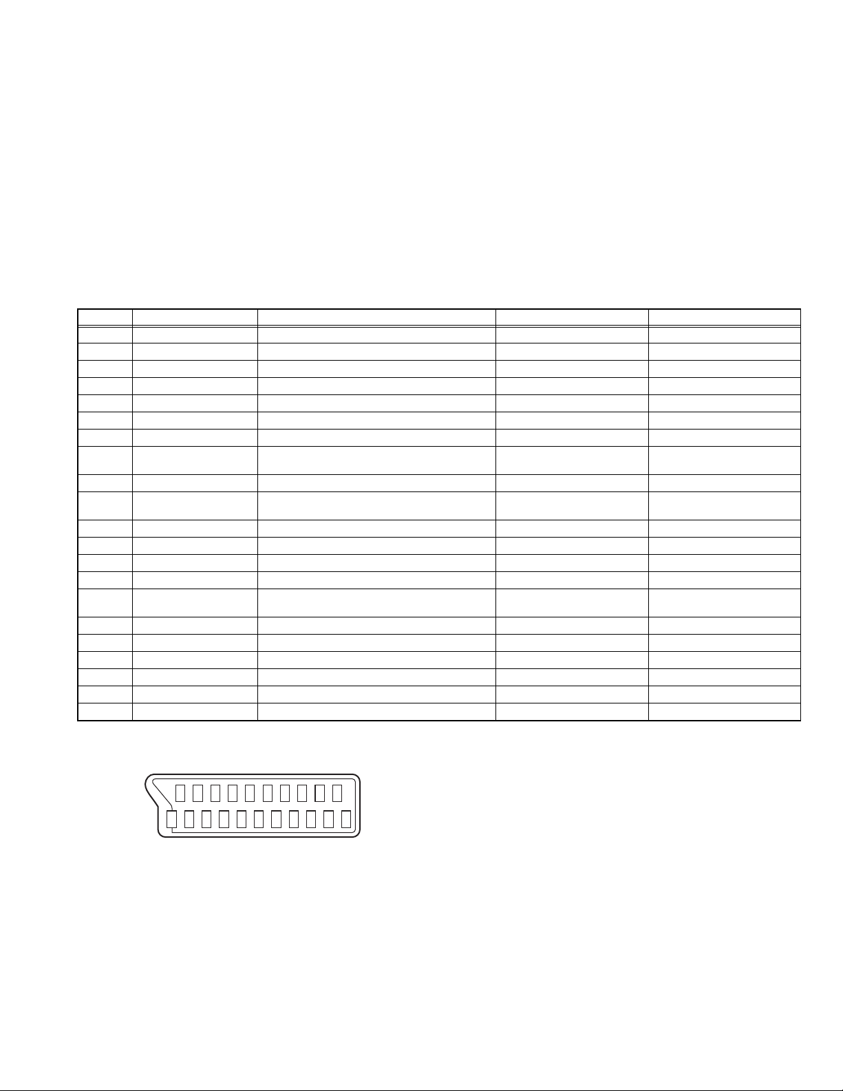
2.2 21-PIN EURO CONNECTOR (SCART) : EXT-1 / EXT-2
Pin No. Signal designation Matching value EXT-1 EXT-2
1 AUDIO R output 500mV(rms) (Nominal),, Low impedance Used (TV OUT) Used (LINE OUT)
2 AUDIO R input 500mV(rms) (Nominal),, High impedance Used (R1) Used (R2)
3 AUDIO L output 500mV(rms) (Nominal),, Low impedance Used (TV OUT) Used (LINE OUT)
4 AUDIO GND Used Used
5 GND (B) Used Used
6 AUDIO L input 500mV(rms) (Nominal),, High impedance Used (L1) Used (L2)
7 B input 700mV
8 FUNCTION SW
(SLOW SW)
9 GND (G) Used Used
10 SCL / T-V LINK Not used Used
11 G input 700mV
12 SDA Not used Used (SDA2)
13 GND (R) Used Used
14 GND (YS) Used Not used
15 R / C input R : 700mV
16 Ys input (FAST SW) Low : 0V-0.4V, High : 1V-3V, 75Ω Used Used
17 GND (VIDEO output) Used Used
18 GND (VIDEO input) Used Used
19 VIDEO output 1V
20 VIDEO / Y input 1V
21 COMMON GND Used Used
Low : 0V-3V
High : 8V-12V, High impedance
C : 300mV
(P-P)
(P-P)
, 75Ω Used Used
(B-W)
, 75Ω Used Used
(B-W)
, 75Ω
(B-W)
, 75Ω
(P-P)
(Negative sync), 75Ω Used (TV OUT) Used (LINE OUT)
(Negative sync), 75Ω Used Used
(P-P= Peak to Peak, B-W= Blanking to white peak)
[Pin assignment]
20 18 16 14 12 10 8 6 4 2
OFF TIMER
This function can set the TV to automatically turn off after a set
time.
COLOUR SYSTEM
If the picture is not clear or no colour appears, change the
current colour system to another colour system.
Used Used
(SCL2 / TV-LINK)
Used (R) Used (C2/R)
21 19 17 15 13 11 9 7 5 3 1
(No.YA303)1-7
Page 9
2.3 TECHNICAL INFORMATION
2.3.1 LCD PANEL
This unit uses the flat type panel LCD (Liquid Crystal Display) panel that occupies as little space as possible, instead of the
conventional CRT (Cathode Ray Tube), as a display unit.
Since the unit has the two polarizing filter that are at right angles to each other, the unit adopts "normally black" mode, where light
does not pass through the polarizing filter and the screen is black when no voltage is applied to the liquid crystals.
2.3.1.1 SPECIFICATIONS
The following table shows the specifications of this unit.
Item Specifications Remarks
Displayed colour 16777216 colours 256 colours for R, G, and B
Brightness 450cd/m
2
Contrast ratio 400: 1
Response time 25ms
View angle Horizontally: 176°, Vertically: 176°
2.3.1.2 PIXEL FAULT
There are three pixel faults - bright fault , dark fault and flicker fault - that are respectively defined as follows.
BRIGHT FAULT
In this pixel fault, a cell that should not light originally is lighting on and off.
For checking this pixel fault, input ALL BLACK SCREEN and find out the cell that is lighting on and off.
DARK FAULT
In this pixel fault, a cell that should light originally is not lighting or lighting with the brightness twice as brighter as originally lighting.
For checking this pixel fault, input 100% of each R/G/B colour and find out the cell that is not lighting.
FLICKER FAULT
In the pixel fault, a cell that should light originally or not light originally is flashing on and off.
For checking this pixel fault, input ALL BLACK SCREEN signal or 100% of each RGB colour and find out the cell that is flashing on
and off.
1-8 (No.YA303)
Page 10
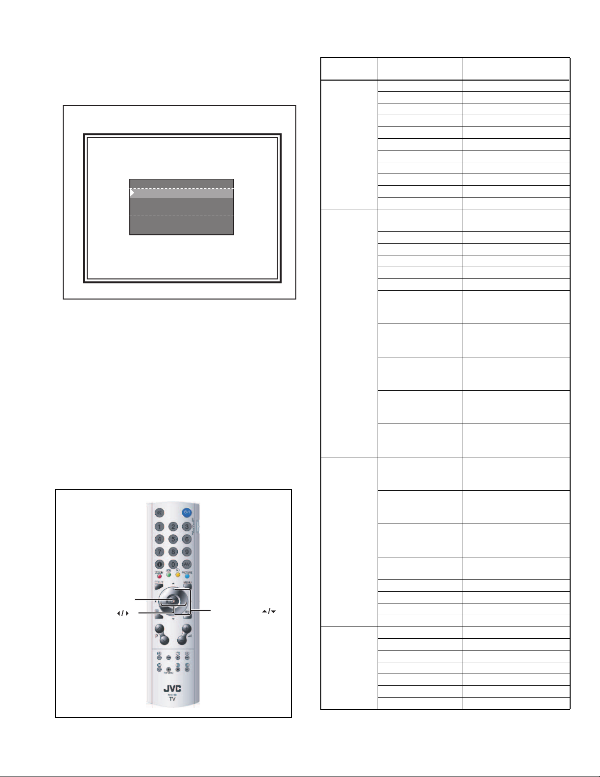
2.4 BASIC OPERATION OF SERVICE MODE
2.4.1 HOW TO ENTER THE SERVICE MODE
(1) Press [INFORMATION] key and [MUTING] key on the
remote control unit simultaneously to enter the SERVICE
MODE SCREEN.
SERVICE MODE SCREEN
Adjust ...
Options ...
Aps Wss Test ...
17JVC 0. 0. 86
Sep 27 2004 08:47:10
2.4.2 HOW TO EXIT THE SERVICE MODE
Press the [MENU] key to exit the Service mode.
2.4.3 CHANGE AND MEMORY OF SETTING VALUE
SELECTION OF SETTING MENU & ITEM
• [FUNCTION /] key : Select the SETTING MENU & ITEM
• [OK] key : Decision the SETTING MENU & ITEM
CHANGE OF SETTING VALUE (DATA)
• [FUNCTION /] key.
MEMORY OF SETTING VALUE (DATA)
The setting value will be stored automatically when release the
REMOTE CONTROL UNIT keys
2.4.4 SERVICE MODE SELECT KEY LOCATION
[OK]
[FUNCTION ]
Service
[FUNCTION ]
2.4.5 SERVICE MODE SETTING ITEMS
Setting
menu
Setting items Contents
Adjust Group ----
Mode ---Col. Temp. ---Contrast ---Brightness ---Colour ---Sharpness ---Red ---Green ---Blue ---Aps Volume ----
Option 1 First APS If ON, TV starts with APS
menu at Start-up
BG ---DK ---I---L---L' ---FM Prs Avl On Adjusts the FM Prescaler
value, when Automatic
Volume Levelling is On
Nicam Prs Avl On Adjusts the Nicam Prescal-
er value, when Automatic
Volume Levelling is On
Scart Prs Avl On Adjusts the Scart Volume
value, when Automatic
Volume Levelling is On
Scart Volume Avl On Adjusts the Scart Volume
value, when Automatic
Volume Levelling is On
FM Prs Avl Off Adjusts the FM Prescaler
value, when Automatic
Volume Levelling is Off
Option 2 Nicam Prs Avl Off Adjusts the Nicam Prescal-
er value, when Automatic
Volume Levelling is Off
Scart Prs Avl Off Adjusts the Scart Prescal-
er value, when Automatic
Volume Levelling is Off
Scart Volume Avl Off Adjusts the Scart Volume
value, when Automatic
Volume Levelling is On
Avl Enable/disable Automatic
Volume Levelling System
Sound ---Carrier ---LDLY ---AGC ----
Aps Wss Test Programme ----
VPS ---Scart Volume Avl Off ---Pdc Format 1 ---Pdc Format 2 ---Name ---WSS ----
(No.YA303)1-9
Page 11

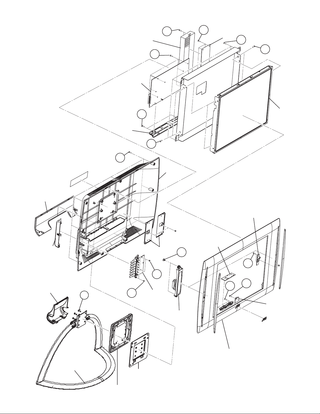
SECTION 3
DISASSEMBLY
3.1 DISASSEMBLY PROCEDURE
NOTE:
• Make sure that the power cord is disconnected from the outlet.
• Pay special attention not to break or damage the parts.
• When removing each board, remove the connectors as required.
• Taking notes of the connecting points (connector numbers) makes service procedure manageable.
• Make sure that there is no bent or stain on the connectors before inserting, and firmly insert the connectors.
3.1.1 REMOVING THE FOOT ASSEMBLY
(1) Remove the HINGE COVER.
(2) Remove the 4 screws [A], then remove the FOOT
ASSEMBLY.
3.1.2 REMOVING THE BACK COVER
• Remove the HINGE COVER & the FOOT ASSEMBLY.
(1) Remove the DOOR SOCKET.
(2) Remove the 9 screws [B].
(3) Remove the BACK COVER toward you.
3.1.3 REMOVING THE AV JACK BRACKET
• Remove the HINGE COVER & the FOOT ASSEMBLY.
• Remove the BACK COVER.
(1) Remove the 2 screws [C].
(2) Remove the AV JACK BRACKET.
3.1.4 REMOVING THE AV JACK PWB
• Remove the HINGE COVER & the FOOT ASSEMBLY.
• Remove the BACK COVER.
• Remove the AV JACK BRACKET.
(1) Remove the 2 screws [D].
(2) Remove the AV JACK PWB.
3.1.5 REMOVING THE FRONT CONTROL PWB
• Remove the HINGE COVER & the FOOT ASSEMBLY.
• Remove the BACK COVER.
(1) Remove the 2 screws [E].
(2) Remove the FRONT CONTROL PWB with FUNCTION
BUTTON.
(3) Remove the FRONT CONTROL PWB from FUNCTION
BUTTON.
3.1.6 REMOVING THE HEADPHONE JACK PWB
• Remove the HINGE COVER & the FOOT ASSEMBLY.
• Remove the BACK COVER.
(1) Remove the 2 screw [F].
(2) Remove the HEADPHONE JACK PWB.
3.1.7 REMOVING THE MAIN PWB
• Remove the HINGE COVER & the FOOT ASSEMBLY.
• Remove the BACK COVER.
(1) Remove the 7 screws [G].
(2) Remove the MAIN PWB.
3.1.9 REMOVING THE SCART BRACKET
• Remove the HINGE COVER & the FOOT ASSEMBLY.
• Remove the BACK COVER.
(1) Remove the 2 screws [K].
(2) Remove the SCART BRACKET.
3.1.10 REMOVING THE MAIN FRAME
• Remove the HINGE COVER & the FOOT ASSEMBLY.
• Remove the BACK COVER.
• Remove the SCART BRACKET.
(1) Remove the 4 screws [L].
(2) Remove the MAIN FRAME from the FRONT PANEL.
3.1.11 REMOVING THE LCD PANEL UNIT
• Remove the HINGE COVER & the FOOT ASSEMBLY.
• Remove the BACK COVER.
• Remove the SCRAT BRACKET.
• Remove the MAIN FRAME.
(1) Remove the 4 screws [M].
(2) Sightly raise the both sides of the LCD PANEL UNIT by
hand from the MAIN FRAME.
NOTE :
• Pay special attention not to break or damage on the LCD
PANEL face or frame.
• The LCD PANEL UNIT is fixed to the FRONT COVER (at the
back side) by using double-side adhesive tapes. To remove
the LCD PANEL UNIT, remove the adhesive tape on the
FRONT PANELslowly.
3.1.12 REMOVING THE SPEAKERS
• Remove the HINGE COVER & the FOOT ASSEMBLY.
• Remove the BACK COVER.
(1) Remove the 2 screws [N].
(2) Remove the SPEAKER from the FRONT COVER.
(3) Follow the same when removing the other hand speakers.
3.1.13 REMOVING THE LED PWB
• Remove the HINGE COVER & the FOOT ASSEMBLY.
• Remove the BACK COVER.
(1) Remove the 2 screws [O].
(2) Remove the LED PWB from the FRONT COVER.
3.1.8 REMOVING THE INVERTER UNIT
• Remove the HINGE COVER & the FOOT ASSEMBLY.
• Remove the BACK COVER.
(1) Remove the 2 screws [H].
(2) Remove the INVERTER SHEELD.
(3) Remove the 4 screws [J].
(4) Remove the INVERTER UNIT.
1-10 (No.YA303)
Page 12
INVERTER
SHEELD COVER
MAIN PWB
INVERTER
H
J
UNIT
L
M
G
SOCKET
DOOR
SIDE AV
DOOR
SCART
BRACKET
B
(X9)
K
M
HANG METAL
BACK
COVER
LCD PANEL
UNIT
HEADPHONE
JACK PWB
FRONT
CONTROL
N
PWB
F
HINGE COVER
FOOT ASSEMBLY
A
FOOT SUPORT
D
AV-JACK
C
PWB
METAL HINGE
BRACKET
SPEAKER
E
FRONT PANEL
O
LED
PWB
(No.YA303)1-11
Page 13
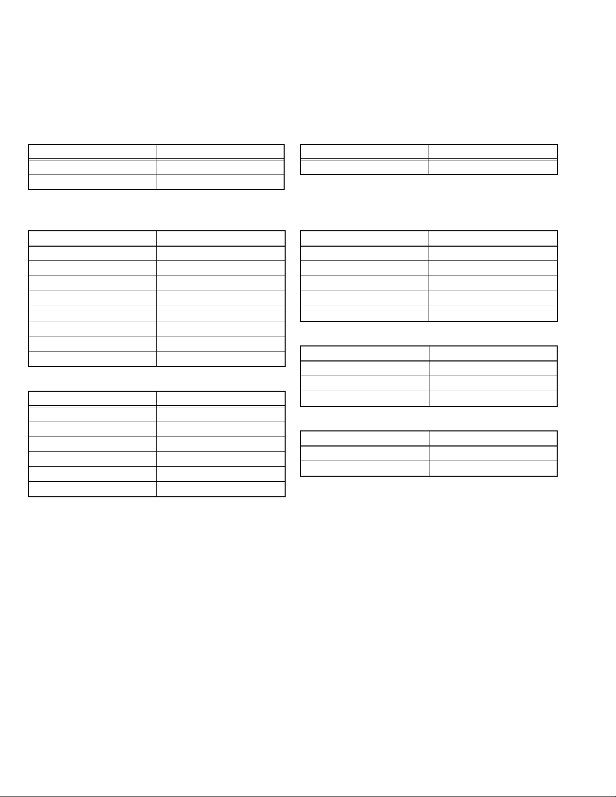
3.2 MEMORY IC REPLACEMENT
• This model uses the memory IC.
• This memory IC stores data for proper operation of the video and drive circuits.
• When replacing, be sure to use an IC containing this (initial value) data.
3.2.1 SETTINGS OF FACTORY SHIPMENT
3.2.1.1 BUTTON OPERATION 3.2.1.2 REMOTE CONTROL DIRECT OPERATION
Setting item Setting position
POWER Off
TV/AV TV
3.2.1.3 REMOTE CONTROL MENU OPERATION
(1) PICTURE
Setting item Setting position
MODE Bright
Contrast 33 Step
Bright-1 26 Step
Sharpness 11 Step
Colour 36 Step
Bright-2 7 Step
Colour Temp. Cool
Nolse Red. Min
(2) SOUND
Setting item Setting position
Volume 10 Step
Bass 16 Step
Treble 15 Step
Balance 16 Step
Hyper Sound Off
Sound Mode Mono
Setting item Setting position
ZOOM AUTO
(3) FEATURES
Setting item Setting position
Sleep Timer Off
Child Lock Off
Language English
EXT-2 Output TV
Blue Back Off
(4) Install [TV MODE]
Setting item Setting position
Colour System Auto
Decorder(EXT-2) On
VCR Off
(5) Install [EXT MODE]
Setting item Setting position
Colour System Auto
VCR Off
1-12 (No.YA303)
Page 14
3.3 REPLACEMENT OF CHIP COMPONENT
3.3.1 CAUTIONS
(1) Avoid heating for more than 3 seconds.
(2) Do not rub the electrodes and the resist parts of the pattern.
(3) When removing a chip part, melt the solder adequately.
(4) Do not reuse a chip part after removing it.
3.3.2 SOLDERING IRON
(1) Use a high insulation soldering iron with a thin pointed end of it.
(2) A 30w soldering iron is recommended for easily removing parts.
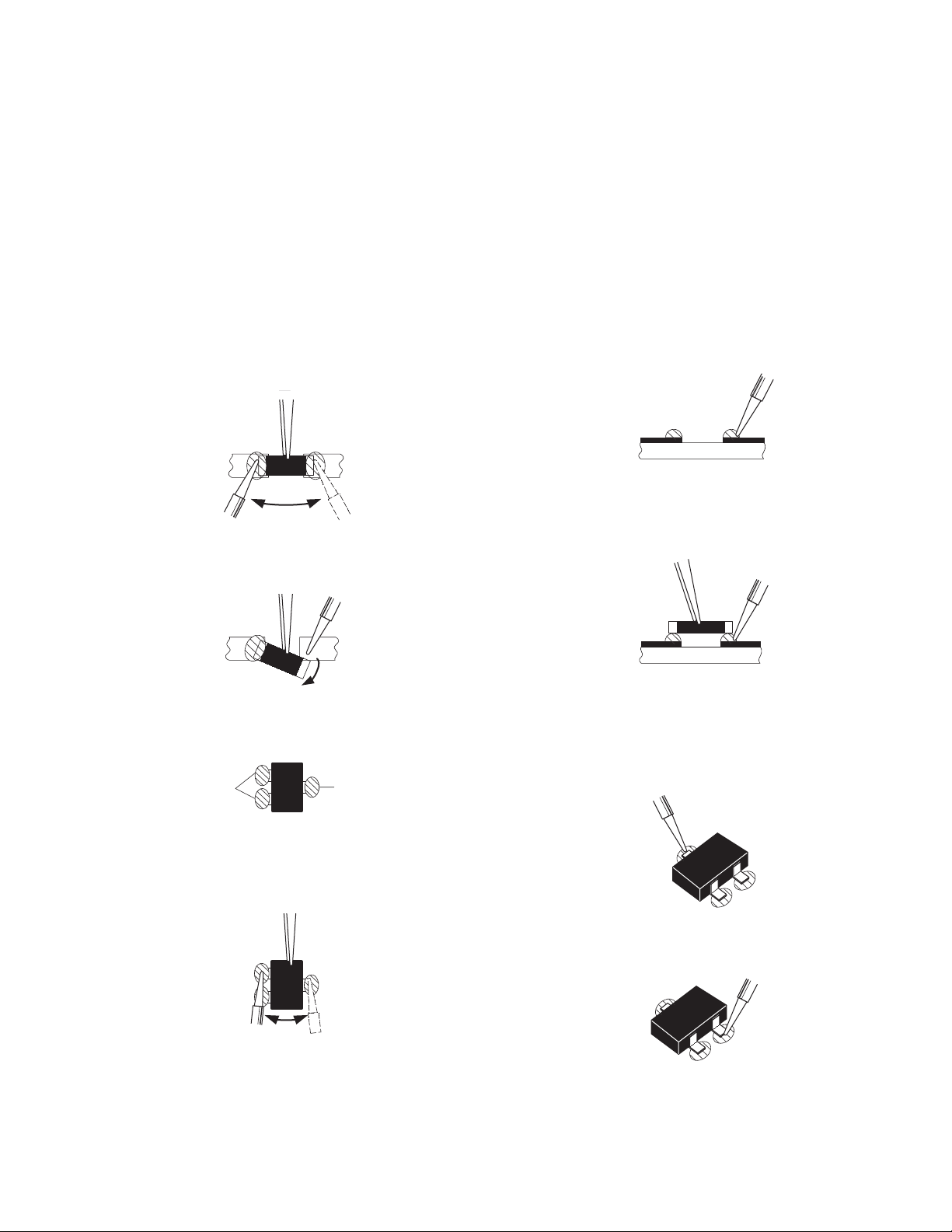
3.3.3 REPLACEMENT STEPS
1. How to remove Chip parts
2. How to install Chip parts
[Resistors, capacitors, etc.]
(1) As shown in the figure, push the part with tweezers and
alternately melt the solder at each end.
(2) Shift with the tweezers and remove the chip part.
[Transistors, diodes, variable resistors, etc.]
(1) Apply extra solder to each lead.
SOLDER
SOLDER
[Resistors, capacitors, etc.]
(1) Apply solder to the pattern as indicated in the figure.
(2) Grasp the chip part with tweezers and place it on the
solder. Then heat and melt the solder at both ends of the
chip part.
[Transistors, diodes, variable resistors, etc.]
(1) Apply solder to the pattern as indicated in the figure.
(2) Grasp the chip part with tweezers and place it on the
solder.
(3) First solder lead A as indicated in the figure.
(2) As shown in the figure, push the part with tweezers and
alternately melt the solder at each lead. Shift and remove
the chip part.
NOTE :
After removing the part, remove remaining solder from the
pattern.
A
B
C
(4) Then solder leads B and C.
A
B
C
(No.YA303)1-13
Page 15

SECTION 4
ADJUSTMENT
This service manual does not describe ADJUSTMENT.
SECTION 5
TROUBLESHOOTING
This service manual does not describe TROUBLESHOOTING.
1-14 (No.YA303)
Page 16

Victor Company of Japan, Limited
AV & MULTIMEDIA COMPANY DISPLAY CATEGORY 12, 3-chome, Moriya-cho, Kanagawa-ku, Yokohama-city, Kanagawa-prefecture, 221-8528, Japan
(No.YA303)
Printed in Japan
VPT
Page 17

LT-20B60SU
ENGLISH
DEUTSCH
FRANÇAIS
ITALIANO
©2004 VICTOR COMPANY OF JAPAN, LIMITED
50066101
1004TKH-VT-VT
LCD PANEL TV
LCD-TV-GERÄT
PANNEAU LCD TELEVISEUR
TV A SCHERMO LCD
INSTRUCTIONS
BEDIENUNGSANLEITUNG
MANUEL D'INSTRUCTIONS
ISTRUZIONI
Page 18
Contents
For your safety
For your safety ......................................... 1
Important Information ............................. 4
Remote Control Buttons .......................... 5
Control Panel Buttons ............................. 6
Using the stand ........................................ 7
How to remove the stand ........................ 7
Installing TV on the wall .......................... 8
Preparation .............................................. 9
Before Switching on your TV .................. 9
Switching the TV ON/OFF ...................... 10
Initial Settings ......................................... 11
Operating the TV .................................... 12
Menu System ......................................... 13
Other Features....................................... 19
PC Mode ................................................. 21
Teletext ................................................... 23
Peripheral Equipment Connections ..... 24
This equipment has been designed and
manufactured to meet international safety standards but, like any electrical equipment, care
must be taken if you are to obtain the best
results and safety is to be assured. So, please
read the points below for your own safety. They
are of a general nature, intended to help you
with all your electronic consumer products and
some points may not apply to the goods you
have just purchased.
Some DOs and DONTs for you
Air Circulation
Leave at least 10cm clearance around the television to allow adequate ventilation. This will
prevent the TV from overheating and consequential possible damage to the TV. Dusty
places should also be avoided.
Heat Damage
Damage may occur if you leave the TV in direct sunlight or near a heater. Avoid places
subject to extremely high temperatures or humidity, or locations where the temperature is
likely to fall below 5ºC (41ºF).
Antenna Connections ............................ 27
Peripheral Equipment Connections ..... 27
PC Input Typical Display Modes ......... 28
Tips ......................................................... 29
Specifications ........................................ 30
Mains Supply
The mains supply required for this equipment
is 220-240 V AC, 50 Hz. Never connect to a
DC supply or any other power source. DO ensure that the TV is not standing on the mains
lead. DO NOT cut off the mains plug from this
equipment, this incorporates a special Radio
Interference Filter, the removal of which will
impair its performance.
Hot / Moderate Climate Conditions
This device is suitable for working in hot and
moderate climate conditions.
ENGLISH - 1 -
Page 19

IF IN DOUBT PLEASE CONSULT A COMPETENT ELECTRICIAN.
DO
DO read the operating instructions before you
attempt to use the equipment.
DO ensure that all electrical connections (including the mains plug, extension leads and
inter-connections between pieces of equipment) are properly made and in accordance
with the manufacturers instructions.
Switch off and withdraw the mains plug before making or changing connections.
DO consult your dealer if you are ever in doubt
about the installation, operation or safety of
your equipment.
DO be careful with glass panels or doors on
equipment.
DO NOT
DONT remove any fixed cover as this may
expose dangerous voltages.
DONT obstruct the ventilation openings of the
equipment with items such as newspapers,
table-cloths, curtains etc. Overheating will
cause damage and shorten the life of the
equipment.
DONT allow electrical equipment to be exposed to dripping or splashing or objects filled
with liquids, such as vases, to be placed on
the equipment.
DONT place hot objects or naked flame
sources, such as lighted candles or nightlights on, or close to the equipment. High temperatures can melt plastic and lead to fires.
DONT use makeshift stands and NEVER fix
legs with wood screws. To ensure complete
safety, always fit the manufacturers approved
stand or legs with the fixings provided according to the instructions.
DONT listen to headphones at high volume,
as such use can permanently damage your
hearing.
DONT leave equipment switched on when it
is unattended, unless it is specifically stated
that it is designed for unattended operation or
has a standby mode. Switch the equipment
off and make sure your family know how to do
this. Special arrangements may need to be
made for infirm or handicapped people.
DONT continue to operate the equipment if
you are in any doubt about it working normally,
or it is damaged in any way switch off, withdraw the mains plug and consult your dealer.
DONT put the empty batteries into garbage
instead of recycle bin to reduce harmfull effects to the environment.
ABOVE ALL NEVER let anyone, especially
children, push anything into holes, slots or
any other openings in the case this could
result in a fatal electric shock.
NEVER guess or take chances with electrical
equipment of any kind it is better to be safe
than sorry.
To fully disconnect the TV, switch off the
mains socket and remove the Power plug.
Safety Precautions for Power adaptor
Be careful! May become hot.
For indoor and dry location use only.
Risk of electric shock.
Shock hazard, do not open.
Keep all power adaptors away from any other
heat source.
Always use power adaptor(s) well-ventilated
area.
** Cold cathode fluoresant lamp in LCD PANEL
contains a small amount of mercury, please
follow local ordinates or regulations for disposal.
"The LCD panel is very high technology product with about a million thin film transistors,
giving you fine picture details. Occasionally,
a few non-active pixels may appear on the
screen as a fixed point of blue, green or red.
Please note that this does not affect the performance of your product." Please note that
certain light guns used with games consoles
may not work on this product.
Warning:
This is a Class A product. In a domestic environment this product may cause radio interference in which case the user may be required to take adequate measures.
ENGLISH - 2 -
Page 20
WARNING : TO PREVENT FIRE OR SHOCK HAZARD, DO NOT EXPOSE THIS APPLIANCE TO
RAIN OR MOISTURE.
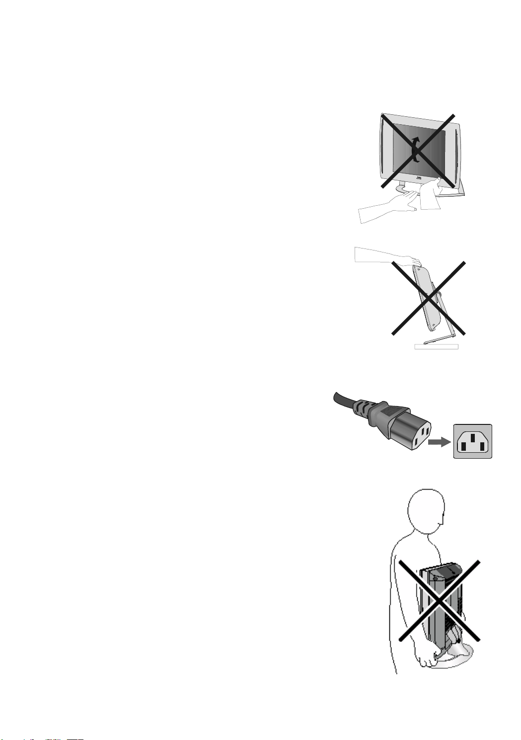
WARNING
Fingers may be trapped under the TV causing injuries.
Hold the TV at the bottom in the middle, and do not allow
the stand to tilt up or down.
The TV may fall causing injuries. Hold the bottom of the
stand with your hand and tilt the TV up and down.
Do not allow children to hang from the TV, place their
elbows on the TV or lean against the TV. Doing so may
cause the TV to fall over and lead to injuries.
CAUTION:
To avoid electric shock or damage to the unit, first firmly
insert the small end of the power cord into the AC Adaptor
unit it is no longer wobbly, and then plug the larger end of
power cord into an AC outlet.
CAUTION:
The TV screen may be damaged if the TV is carried as
shown in the diagram.
The TV should always be carried by two people.
ENGLISH - 3 -
Page 21

Important Information
Please take note
EXCLUSION CLAUSE
JVC shall under no circumstances be liable for loss and/or damage to the product caused
by:
fire;
earthquake;
accidental damage;
intentional misuse of the product;
use of the product in improper conditions;
loss and/or damage caused to the product whilst in the possession of a third party;
any damage or loss caused as a result of the owner s failure and/or neglect to follow the
instructions set out in the owners manual;
any loss or damage caused directly as a result of misuse or malfunction of the product
when used simultaneously with associated equipment;
Furthermore, under no circumstances shall JVC be liable for any consequential loss and/
or damage including but not limited to the following, loss of profit, interruption of business,
the loss of recorded data whether caused during normal operation or misuse of the
product.
WARNING! NEVER LEAVE A
Care and disposal
STATIONARY IMAGE ON THE
SCREEN
If stationary images generated by TELETEXT,
CHANNEL IDENTIFICATION LOGOS, COMPUTER DISPLAYS, VIDEO GAMES, ON
SCREEN MENUS, etc. are left on the TV
screen for any length of time, they could become permanently ingrained.
If you use your television to display completely
still images, or moving pictures which have a
permanent still image superimposed e.g.
broadcast network logos, it is always advisable to reduce BOTH the brightness and contrast settings.
Cleaning the screen and cabinet...
Turn off the power, clean the screen and cabinet with a soft, dry cloth. We recommend that
you do not use any proprietary polishes or
solvents on the screen or cabinet as this may
cause damage.
Disposal...
When the set reaches the end of its useful
life please dispose of it in accordance with
Local Government Regulations or at a recycling centre.
ENGLISH - 4 -
Page 22
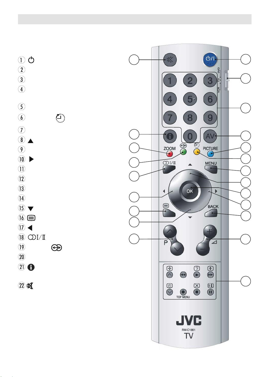
Remote Control Buttons
/ I = (Stand By) button
TV / VCR / DVD Switch
Number buttons
A V button (TV, EXT-1, EXT-2, EXT-2 S,
EXT-3, EXT-3 S or PC)
BLUE / PICTURE Mode button
YELLOW / Sleep Timer button
MENU button
= Cursor Up button
OK button
= Cursor Right button
BACK button
Volume Up/Down buttons
Teletext / VCR /DVD Control buttons
Programme Up/Down buttons
= Cursor Down button
= Teletext Button
= Cursor Left button
= Stereo / Bilingual button
GREEN / Hyper Sound On/Off button
RED / ZOOM Mode button
= Information Button / T-V Link in
Program Menu
= Mute button
ENGLISH - 5 -
Page 23
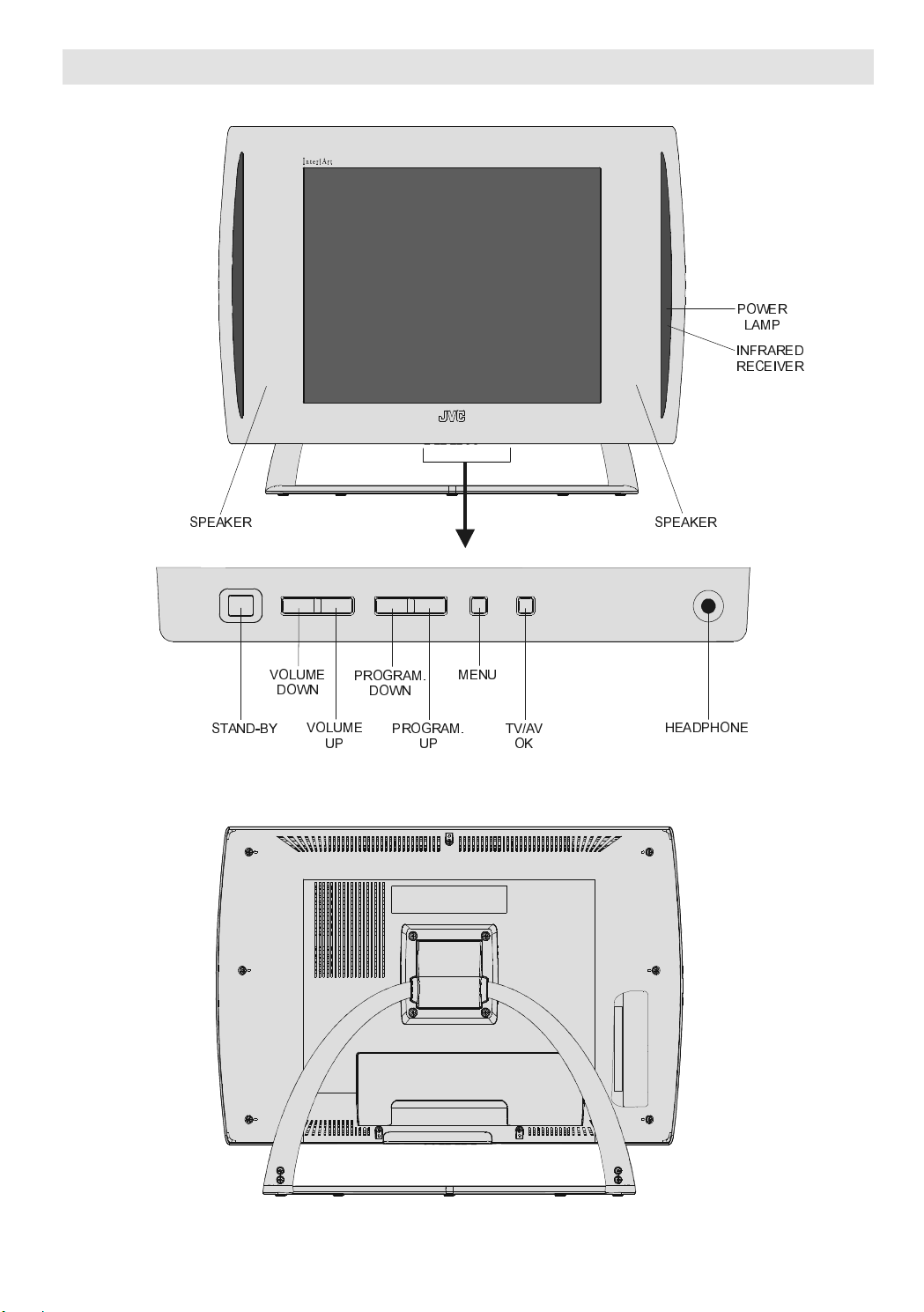
Control Panel Buttons
63($.(5 63($.(5
32:(5
/$03
,1)5$5('
5(&(,9(5
67$1'%<
92/80(
'2:1
92/80(
352*5$0
83
'2:1
352*5$0
83
0(18
79$9
2.
+($'3+21(
ENGLISH - 6 -
Page 24

Using the stand
This TV comes with a Table Top Stand already attached.
This stand can be used to adjust the direction of the TV screen.
Tilt the TV up and down:
While holding the stand with one hand which should be on lower level of the stand for avoiding
trapping, use your other hand to hold the middle of the top of the TV and slowly tilt the TV up and
down.
How to remove the stand
5(029(7+(
6&5(:6
67$1'
ENGLISH - 7 -
Page 25

Installing TV on the wall
WARNING
When you install the TV on the wall, only use a JVC wall mounting unit (optional) which is
designed for this TV.
Make sure that the TV is installed on the wall by a skilled installer.
Locate the TV away from direct sunlight and strong lights, soft, indirect lighting is recommended
for comfortable viewing. Place on a sturdy platform, the mounting surface should be flat and
steady, it should then be secured to the wall with a sturdy tie using the hook on the back of the
TV, this will prevent it from falling over. Use curtains or blinds to prevent direct sunlight falling on
the screen.
A floor and table top stand are available for this television, or and angled bracket which enables
the TV to be wall-mounted.
The LCD display panels are manufactured using an extremely high level of precision technology, however sometimes some parts of the screen may be missing picture elements or have
luminous spots. This is not a sign of a malfunction.
Make sure the TV is located in a position where it cannot be pushed or hit by objects, as
pressure will break or damage the screen.
100 mm mount based on VESA regulation is equipped.
ENGLISH - 8 -
Page 26

Preparation
,1387'& 9
WHUPLQDO
$&DGDSWRU
795($53$1(/
&$%/(79
Install Display on solid horizontal surface such
as a table or desk.
NTSC Playback.
PLL (Channel Search)
PC input (Support Up to 1024 x 768)
For ventilation, leave a space of at least 10 cm
free all around the set. To prevent any fault
and unsafe situations, please do not place
any objects on top of the set.
Features
It is a remote controlled colour television and
PC monitor.
100 programmes from VHF, UHF bands or
cable channels can be preset.
It can tune cable channels.
Controlling the TV is very easy by its menu
driven system.
It has 2 pieces of Euroconnector socket for
external devices (such as video, video
games, audio set, etc.)
Optional stereo sound systems (German or
German+Nicam) are available.
Multilanguage OSD.
Teletext (Fastext, 7 pages).
Before Switching on your TV
Power connection
Only use the adaptor supplied with this product.
7R3 2: ( 5
IMPORTANT: The TV set is designed to operate on 12 V DC. For this, an adaptor is used
which gives 12V DC voltage. Connect this
adaptor to a system that supplies 220-240V
AC, 50 Hz.
After unpacking, allow the TV set to reach the
ambient room temperature before you connect the set to the mains.
Connections to the RF input
socket
Connect the aerial or cable TV plug to the RF
input socket located at the back of the TV
and connect the cable plug coming out from
the TV out socket located at the devices (VCR,
DVB etc.) to this socket as well.
It is possible to connect headphone.
A.P.S. (Automatic programming system)
All programmes can be named.
Forward or backward automatic tuning.
Sleep timer.
Child lock
Auto, 4:3, 16:9
Automatic sound mute when no transmis-
sion.
When no valid signal is detected, after 5 min-
utes the TV switches itself automatically to
stand-by mode.
ENGLISH - 9 -
Page 27

How to connect other devices
Switching the TV ON/OFF
IMPORTANT: Switch off the TV before connecting any external device.
Sockets for external connections are at the
back of the TV. For connection of other devices
via Euroconnector refer to the manuals of the
related devices.
Inserting batteries in the remote
control handset
Remove the battery cover located on the back
of the handset by gently pulling downwards
from the indicated part.
Insert two AA/R6 dry cell or equivalent type of
batteries inside.
Replace the battery cover.
To switch the TV on
Your TV will switch on in two steps:
1- Connect the power supply cord to the sys-
tem. Then the TV switches itself to standby mode and the power lamp becomes red.
2- To switch on the TV from stand-by mode
either:
Press the
or at the bottom of the TV,
or,
Press a digit button on the remote control so
that a programme number is selected,
or,
Press or buttons on the remote
control or at the bottom of the TV, so that last
switched off programme is selected.
Either way the TV will switch on and the power
lamp will become green.
/ I button on the remote control
NOTE: Remove the batteries from remote control handset when it is not to be used for a long
period. Otherwise it can be damaged due to
any leakage of battery.
Old batteries must be disposed in a designated area. If performance of the remote control reduces, replace the batteries with the correct type. Do not combine a used, old battery
or a new one or mixed battery types. Remove
dead batteries immediately to prevent acid
from leaking into the battery compartment.
To switch the TV off
Press the / I button on the remote control
or at the bottom of the TV, so the TV will switch
to stand-by mode and the power lamp will
become red.
NOTE: To switch the TV off completely remove
the mains plug from the socket.
ENGLISH - 10 -
Page 28

Initial Settings
79/LQN
'2:1/2$'79!9&5
75$16)(5
T-V Link
First A.P.S. (Automatic
Programming System)
When you turn the TV on for the first time, the
first APS menu appears.
APS, searches and sorts all channels and
stores them automatically on your TV, according to the transmission of programme systems in your area.
To cancel APS before starting, press BLUE
button.
First of all choose the Language which the
menus of the TV will appear. As soon as you
change the language, the menu items will be
displayed in the selected language. By pressing the
try item and select the country. This will affect
the sort process in APS. Press Red button to
start A.P.S.
After APS is finalized, a programme list will
appear on the screen. In the programme list
you will see the programme numbers and
names assigned to the programmes.
If you press the BLUE button at any time while
the A.P.S. is running, the A.P.S. will be ended.
or button, come to the Coun-
When a T-V Link compatible VCR connected
to the EXT-2 terminal on the TV, it is easier to
set up the VCR and to view videos. T-V Link
uses the following features:
To use T-V Link functions
A T-V Link compatible VCR means a JVC
video cassette recorder with the T-V Link logo,
or with one of the following logos. For details
see your VCR instruction manual.
Q-LINK (A trademark of Panasonic Corporation)
Data Logic (A trademark of Metz Corporation)
Easy Link (A trademark of Philips Corporation)
Megalogic (A trademark of Grundig Corporation)
SMARTLINK (A trademark of Sony Corporation)
Downloading data to VCR:
The VCR will automatically download the registered data on the TV channels from the TV.
This means you do not need to set up the
programme channels on your VCR manually.
The T-V Link menu will be displayed when
you press the
menu is displayed.
button while Program
If you do not accept the locations and / or the
programme names of programmes, you can
change them in Program menu. For details
see Program menu on page 17.
If you do not have a T-V Link compatible VCR,
press MENU button to exit the menu.
If you have a T-V Link compatible VCR con-
nected to the EXT-2 terminal, press
ton to display T-V Link menu. Then follow the
operating procedure Downloading data to
VCR in the following T-V Link section.
but-
ENGLISH - 11 -
If you do not have a T-V LINK compatible VCR,
select Cancel and press
exit the menu.
Press or OK button to start downloading
data to VCR. TRANSFER is displayed in the
menu.
or OK button to
Page 29

If FEATURE NOT AVAILABLE is displayed,
download was not performed correctly. Before
trying to download again, check that:
The VCR power is turned on.
The VCR is T-V Link compatible.
The VCR is connected to the EXT-2.
The scart cable is fully wired.
Direct REC:
You can easily record to VCR the images that
you are watching on the TV. For details, read
the manual for your VCR. Use your VCR con-
trols. You can not carry out Direct REC using
your TV control.
When the VCR is not ready (For example when
there is no tape inserted), NO RECORDING
is displayed. In the following situations, the
VCR will stop recording if the Tv is turned off, if
the TV channel or input is changed, or if the
menu is displayed on the TV:
When recording images from an external
device connected to TV (For example
camcorder).
When recording a TV channel after it has
been unscrambled on a decoder.
When recording a TV channel by using the
TVs output because the VCRs own tuner
can not properly receive that channel.
TV autopower on/VCR image view:
When the VCR starts playing, the TV automatically turns on and images from EXT-2 appear
on the screen.
This function does not happen if your TVs main
power is turned off. Set your TVs main power
to on (StandBy Mode).
Operating the TV
You can operate your TV using both the remote control handset and onset buttons.
Volume setting and programme selection can
be made by using the buttons on the bottom
of the TV.
Operating with the buttons on the
TV
Volume Setting
Press - button to decrease volume or
+ button to increase volume, so a vol-
ume level scale (slider) will be displayed at
the middle of the bottom on the screen.
Programme Selection
Press P
gramme or
ous programme.
Switching input mode
Pressing TV/AV/OK button will change the
input mode.
Entering Main Menu
Press MENU button to enter Main menu. In
the Main menu select submenu using
P or P button and enter the sub-menu
using -
learn the usage of the menus, refer to the
Menu System sections.
Operating with Remote Control
The remote control handset of your TV is designed to control all the functions of the model
you selected. The functions will be described
in accordance with the menu system of your
TV.
button to select the next pro-
P button to select the previ-
/ + or TV/AV/OK button. To
Functions of the menu system are described
in following sections.
Volume Setting
Press
Press
volume level scale (slider) will be displayed in
the middle at the bottom of the screen.
ENGLISH - 12 -
+ button to increase volume.
- button to decrease volume. A
Page 30

Menu System
Your TV has been designed with a menu system to provide an easy manipulation of a multifunction system. The TV is controlled by choosing the commands, which are displayed on
the screen.
Programme Selection (Previous or next
programme)
Press
button to select the previous
programme.
Press
button to select the next
programme.
Programme Selection (direct access)
Press digit buttons on the remote control to
select programmes between 0 and 9. TV will
switch to the selected programme. To select
programmes between 10 - 99, press the digit
buttons consecutively which programme you
want to select (eg. for programme 27, first
press 2 and then 7). When it is late to press
second digit button only the first digit
programme will be displayed. The limit of the
delay time is 3 seconds.
Example: PR6 press 6
PR12 press 1 and 2
Press directly the programme number to
reselect single digit programmes.
Hint: The channel list numbers are assigned by the broadcasters. Because not all channels are broadcast free-to-air
and stored by the receiver, the channel list numbers do not
run continuously. The fifteenth channel in the list, for example, may not be channel number 15 but channel number
17.
MAIN MENU
Press the MENU button. The main menu will
be displayed in the middle of the screen.
To select a sub-menu use or but-
ton, and press or button or directly
press OK button.
In EXT-1, EXT-2 and EXT-3 modes, main menu
appears the same as in TV mode but without
Program sub-menu.
Menu does not disappear automatically if it is
left on the screen.
Press the MENU button again to remove
menu.
Press the BACK button to return to the pre-
vious menu.
Picture Menu
Press MENU button, now you are in main
menu. In the Main menu, select Picture using
or button, then enter the Picture
menu by pressing / or OK button.
Setting Mode
As you enter the picture menu, Mode will be
the first item.
By pressing or button you may
choose one of these options:
Soft, Standard and Bright.
ENGLISH - 13 -
Page 31

Setting Contrast
Setting Colour
Using
Press
Press
Setting Bright-1
Using
Press button to increase brightness.
Press
or button select Contrast.
button to increase contrast level.
button to decrease contrast level.
or button select Bright-1.
button to decrease brightness.
Using
Press
Press
Setting Bright-2
Using
Press
Press
or button select Colour.
button to increase colour level.
button to decrease colour level.
or button select Bright-2.
button to increase the back light.
button to decrease the back light.
Setting Sharpness
Using
Press
Press
level.
or button select Sharpness.
button to increase sharpness level.
button to decrease sharpness
Setting Colour Temp.
Using
Press
Cool or Normal.
Setting Noise Reduction
Using
Press or button to select Noise Re-
duction level Off or Minimum or Medium
or Maximum.
ENGLISH - 14 -
or button select Colour Temp.
or button to select Warm,
or button select Noise Red.
Page 32

Note 1:
At low signal level, the changings on the Noise Reduction
function are not effective when there is menu on the screen.
If the menu is removed, the effect of this function is seen. At
normal broadcasting, Noise Reduction changings are effec-
tive at once.
Note 2:
At moving pictures, while Noise Reduction is at maximum
level, some picture distortions may occur. If Noise Reduc-
tion is set to medium or minimum, the picture will improve.
Setting Hue
Or you can directly change the volume settings using
+ (to increase) or - (to
decrease) button.
Setting Bass Level
Using
or button select Bass Level.
Press button to increase bass level.
Press
button to decrease bass level.
Setting Treble Level
During Playback NTSC system, this will appear in AV mode only when NTSC video source
is applied. Otherwise, Hue option is invisible
in Picture menu in TV mode :
Using
Press
Press
or button select Hue.
button to increase hue level.
button to decrease hue level.
Center value is indicated with one arrow.
Reset
Press BLUE button to reset the picture modes
to factory default settings.
To Store the Settings
In the Picture Menu, all settings are stored
automatically.
Sound Menu
As you enter the main menu, sound will be the
second item. In the main menu, select Sound
using
menu by pressing / or OK button.
or button, then enter the sound
Using or button select Treble.
Press
Press
button to increase treble level.
button to decrease treble level.
Setting Balance
It allows adjusting the distribution between the
left and right speakers.
Using
or button select Balance.
Press button to change balance right-
ward.
Press button to change balance leftward.
Hyper Sound
Using or button select Hyper Sound.
Pressing or button will turn this fea-
ture on or off.
Pseudo/spatial effect can be turned on or off
via the Hyper Sound item in the Sound menu
or by remote control. In Mono transmission
the left and right channels will be added at left
channel and dummy stereo effect will be introduced to end-user.
Setting Volume
As you enter the sound menu, Volume will be
the first selected option.
Press
Press
button to increase volume.
button to decrease volume.
ENGLISH - 15 -
In stereo transmission it yields a phase difference between left and right channels. Hyper
Sound selection will be displayed on the
screen when the TV Status button is pressed
or programme is changed.
Selecting Sound Mode
Using
or button select Sound
Mode.
Press
or button to change Sound
Mode.
You can choose Mono, Stereo or Dual
(I-II) mode, only if the selected channel supports that Sound Mode.
Page 33

You can also change sound mode directly by
pressing I-II button on your remote control.
In case of bilingual broadcast (Dual Sound),
you can select original or dubbed language
using mode option. So when somebody listens to the original language from the loudspeakers, somebody else can listen to the
dubbed language from headphone.
To Store The Settings
In the Sound Menu, all settings are stored
automatically.
Feature Menu
Press MENU button, now you are in main
menu. In the main menu, select Feature using
menu by pressing
or button. Then enter the Feature
/ or OK button.
Selecting Menu Language
Using
Press
guage.
EXT-2 Output
From EXT-2 Output; TV, EXT-1 or EXT-3 can be
given. These modes can be chosen by press-
ing
Blue Back (During No Signal)
or button select Language.
or button to select menu lan-
or button on EXT-2 Output.
Sleep Timer
The Sleep Timer is used to turn the TV off after
a defined period of time after selecting this
item. The timer can be programmed between
Off and 120 minutes in steps of 10 minutes.
(Off, 010, 020, 030, 040, ... , 120)
If sleep timer is activated, at the end of the
selected time, the TV goes automatically to
stand-by mode.
Child Lock
You can use this feature to prevent children
turning the TV on/off or changing programmes
or adjustments etc. without remote control.
Using
or button select Child Lock.
The Blue Back Feature can be set by
button to either On or Off.
To Store Settings
In Feature menu all settings are stored automatically.
or
Install Menu
Press MENU button, now you are in main
menu. In the main menu, select Install us-
ing
menu by pressing / or OK button.
or button. Then enter the Install
Press / button to select Child Lock
On or Off .
When Off is selected, there will be no differ-
ence in the operation of your TV. When On is
selected, the TV can only be controlled by the
remote control handset. In this case the con-
trol panel buttons, except
bottom of the TV will not work.
button, at the
ENGLISH - 16 -
In EXT mode, Install menu appears like this:
You can change only Colour system and
VCR.
Page 34

Selecting Programme
Using
To select programme number, you can use
/ button or Digit Buttons.
Selecting Band
or button select Programme.
EXT-2 output will be chosen as TV mode only
and any scrambled channels will be unscrambled through decoder connected your
TV via EXT-2 output.
Setting VCR (Video Cassette Recorder )
Mode
Band, can be chosen either,
C or S by
Selecting Channel
Channel can be changed by or button
or by Digit Buttons.
Selecting Colour System
Using
you can change the colour system to PAL,
SECAM or Auto.
Note: In EXT mode, you can choose NTSC
3.58 and NTSC 4.43 as well.
Selecting Sound System
Using or button on Sound System,
you can change the standard to BG, DK, I, L,
Lp.
Selecting Fine Tuning
You can use the Fine Tuning process for fine
adjustment (after coarse adjustment), if you
are not happy about the image on the screen.
Use
until getting the best image on the screen.
Selecting Search
To start the search process, press
or button on Colour System,
or button on Fine Tuning item,
or button.
button
This item can be seen in TV, EXT-1, EXT-2
and EXT-3 modes.
If you want to watch a VCR source from one of
these modes, then it will be better to set
VCR mode on. For this, while the cursor is
on this item press the
set it On.
If you want to watch a DVD , then you must set
this item off; because DVD is not a source
like a VCR and to see the picture better, you
must set the VCR mode Off.
To Store Settings
Press
tion to store Install menu settings.
After stored, T-V Link menu will appear. If you
do not need to do T-V Link, select Cancel
and press
/ or OK button on Store op-
or OK button to exit the menu.
or buttons to
Program Menu
Press MENU button, now you are in main
menu. In the main menu, select Program
using
Programme menu by pressing / or
OK button.
Note: There is no Program menu in any EXT
modes.
or button. Then enter the
for forward search or button for backward
search. If a signal is found or reaches to end
of the band after searching, press
buttons to continue search process. To stop
the search process when you want, press
or buttons at any time.
Decoder(EXT-2)
You can use this mode to connect any decoder to your TV.
Press the
Off.
When you select Decoder(EXT-2) On,
or buttons to set it On or
or
ENGLISH - 17 -
Page 35

Program Menu is used to delete a channel, to
change the programme number of a channel,
to give a channel name to a channel, and to
start the A.P.S (Autostore) function.
To choose a channel in the PROGRAM
menu
To change the programme number of a
channel (Insert)
1. Choose the channel you want to change
the programme number.
2. Press the GREEN button to enter the Insert
mode.
Press
Caution:
Using Delete or Insert function rewrite the current channel list in the Program menu. Therefore, the programme num-
bers of some of channels will change.
/ / / buttons.
When you complete the settings of
Program menu:
If you have a T-V LINK compatible VCR, press
button to display the T-V LINK menu. Then
follow the operating procedure Downloading
the data to VCR.
If you do not have a T-V LINK compatible VCR,
select Cancel and press
or OK button to
exit the menu.
To give a channel name (Name):
1. Choose the channel you want to give a channel name.
2. Press the RED button to enter the Name
mode.
3. Press
position,and press
or button to choose the
or button to
choose each character of channel name.
4. Press the RED button to store the channel
name.
To cancel the NAME mode, press the BLUE
button.
To delete a channel (Delete):
1. Choose the channel you want to delete.
2. Press the YELLOW button to enter the Delete mode.
3. Press the YELLOW button to delete it.
To cancel the Delete mode, press the BLUE
button.
3. Press
/ / / buttons to choose
new programme number.
4. Press the GREEN button to insert the channel to the chosen programme number.
Autostore:
To enter Autostore menu, press the BLUE button. To learn the features of this function see
Autostore below.
Autostore, searches and stores all channels
automatically on your TV, according to the
transmission of programme systems in your
area.
First of all choose the Country by using
or
button.
After Autostore is finalized, a programme list
will appear on the screen. In the program list
you will see the programme numbers and
names assigned to the programmes.
If you do not accept the locations and/or the
programme names of programmes, you can
change them in Programme menu.
Source Menu
You can switch your TV to EXT modes by
pressing directly to AV button or by selecting
in source menu from the main menu.
While in EXT mode, you can also switch your
TV to TV or other EXT modes by selecting in
source menu from the main menu.
In main menu, firstly use or button
then use / or OK button to enter
Source menu. In source menu, move the cursor by
button or / buttons when the cursor is
or button and then press OK
ENGLISH - 18 -
Page 36

on the required item. The selected mode
comes automatically on the screen.
6RXUFH 79
79
(;7
(;7
(;76
(;7
(;76
3&
Other Features
TV Status
Programme Number, Programme Name (or
EXT), (they are displayed on the upper left of
the screen). The sound indicator is displayed
with them too. They are displayed after
programme change for 3 seconds.
Sound Indicator
The alternatives of the indicator are Mono, Stereo, Dual I and Dual II. This indicator is displayed under the programme number indicator on the screen. I-II button is used to select
Mono or Stereo, or Dual I or Dual II.
0RQR
In Mono broadcast or in forced-mono (for stereo broadcast).
6WHUHR
In Stereo broadcast.
'XDO,
In stereo transmission it yields a phase difference between left and right channels. Hyper
Sound selection will be displayed on the
screen when the TV Status button is pressed
or programme is changed.
Picture Mode
Picture mode OSD is displayed when BLUE
button is pressed. Picture mode can be
changed to standard, soft and bright.
Sleep Timer
Sleep Timer mode OSD is displayed when
YELLOW button is pressed.
The Sleep Timer is used to turn the TV off after
a defined period of time after selecting this
item. The timer can be programmed between
Off and 120 minutes in steps of 10 minutes.
(Off, 010, 020, 030, 040, ... , 120)
If sleep timer is activated, at the end of the
selected time, the TV goes automatically to
stand-by mode.
If dual broadcast detected. Dual I is selected
in default and also can be selected after Dual
II by Remote Control.
'XDO,,
If Dual II is selected by Remote Control.
Hyper Sound
By selecting Hyper Sound in sound menu or
by pressing the
control, Pseudo/Spatial effect can be turned
on or off. In Mono transmission the left and
right channels will be added at left channel
and dummy stereo effect will be introduced to
end-user.
button on your remote
ENGLISH - 19 -
Mute Indicator
It is placed in the upper middle of the screen
when enabled, and it stays there until it is disabled.
To cancel mute, there are two alternatives; the
first one is by pressing the button, this
volume is set to the preceding value, and the
second one is increasing or decreasing the
volume level.
Page 37

No-Signal Detection (TV mode)
Zoom Modes
If no valid signal detected, it takes 5 minutes
to switch to the Stand-By mode unless any
signal detected or any Remote Control command is accessed.
After a Remote Control command (if No-Signal Timer is active) the timer stops and if no
signal detected again the timer is initialized to
5 minutes and starts 3 seconds later again to
count down.
It is not valid in EXT modes.
No-Signal and Out Of Range
Detection (PC mode)
In PC Mode, as no menu is displayed, in case
that there is no PC input to the TV, it is displayed an OSD message:
No input signal detected
In PC Mode, if the resolution and the vertical
frequency is not supported by the concept, it is
displayed an OSD message:
Zoom mode can be changed by pressing Red
button. You can change the screen size according to the picture aspect ratio. Select the
optimum one from the following ZOOM modes:
Auto, 4:3 and 16:9.
AUTO
When a WSS (Wide Screen Signalling) signal, which shows the aspect ratio of the picture, is included in the broadcast signal or the
signal from an external device, the TV automatically changes the ZOOM mode to 4:3 or
16:9 according to the WSS signal.
When the AUTO mode does not function cor-
rectly due to poor WSS signal quality or when
you want to change the ZOOM mode, change
to another ZOOM mode manually.
Signal out of range
Volume Bar
It is displayed in the lower middle of the screen.
When a volume command is received (press-
ing
Control panel at the bottom of the TV) and no
menu is active, it stays on the screen for 3
seconds, after the last volume command or
until another command is received in between.
EXT Modes
By pressing the AV button you can switch
your TV to EXT modes (except being in Teletext). Pressing this button consecutively will
switch the TV in one of the optional EXT
modes: EXT-1, EXT-2, EXT-2 S, EXT-3,
EXT-3 S and PC.
In order to quit the EXT mode press any digit
buttons or
+ or - by Remote Control or
or
ENGLISH - 20 -
Page 38

PC Mode
Installation
Power off both Computer and Display before
making any connections.
Set your PCs resolution correctly before con-
necting to the TV. See the table in page 28 for
supported modes.
Use a D-SUB cable to connect the TVs PC
input to the computers RGB output terminal. If you want to listen to the sound from the
computer, use an audio cable to connect the
PC AUDIO IN to the computers sound output terminal.
3LQ0LQL'6XE&RQQHFWRU
Auto Position
If you shift the picture horizontally or vertically
to an unwanted position, use this item to put
the picture into correct place automatically.
Select Auto position item by using
buttons.
or
Press OK button.
Press MENU button or BACK button to store
the value.
Warning: Auto position adjustment recommended to be done with the full screen image
for the proper adjustment.
Horizontal Position
This item shifts the image horizontally to right
hand side or left hand side of the screen.
Tighten the screws of the Display cable until
the connectors are fastened securely (finger-tighten only).
Main Menu in PC mode
Enter the main menu by pressing the MENU
button on the remote control.
3&0HQX
3&3LFWXUH3R VLWLRQ
3&3LFWXUH
6RXQG
6RXUFH
[
+N+] 9+]
PC Picture Position Menu
Select Hori. Position item by using
button.
or
Use or button to adjust the value.
Press MENU button or BACK button to store
the value.
Vertical Position
This item shifts the image vertically towards
the top or bottom of the screen.
Select Ver. Position item by using
button.
or
Use or button to adjust the value.
Press MENU button or BACK button to store
the value.
Dot Clock
Dot Clock adjustments correct interference
that appear as vertical banding in dot intensive presentations like spreadsheets or paragraphs or text in smaller fonts.
In the Main menu, select PC Picture Posi-
tion using or button, then enter the
menu by pressing
/ or OK buttons.
ENGLISH - 21 -
Use
or button to adjust the value.
Clock Phase
Depending on the resolution and scan frequency that you input to the TV Set, you may
see a muddy or noisy picture on the screen. In
such a case you can use this item to get a
clear picture by trial and error method.
Use
or button to adjust the value.
Page 39

PC Picture Menu
Sound in PC mode
In the Main menu, select PC Picture using
or button, then enter the PC Picture
menu by pressing / or OK buttons.
Contrast, Bright-1 and Colour Temp. adjust-
ments in this menu are identical to adjustments defined in TV picture menu.
R, G, and B adjust the TV image colour in PC
mode. You can change the TV colour to your
desired colour: R (Red), G (Green), B (Blue)
Press the BLUE button to reset the PC picture
settings to default factory settings.
Sound Menu
Connect the PCs Audio output to the TVs PC
Audio In socket with an audio cable.
In the main menu select Sound using
or
button then enter the Sound menu by
pressing / or OK buttons.
The items in this menu are described at
Sound menu starting page 15.
Source Menu
In the Main menu, select Source using
or button, then enter the Source menu by
pressing
Select the available sources of TV, EXT-1,
EXT-2, EXT-2 S, EXT-3, EXT-3 S or PC using
/ or OK buttons.
6RXUFH 3&
79
(;7
(;7
(;76
(;7
(;76
3&
or button and by pressing /
or OK buttons.
ENGLISH - 22 -
Page 40

Teletext
Teletext is an information system that displays
text on your TV screen. Using the Teletext information system you can view a page of information on a subject that is available in the
list of contents (index).
buttons. The page will be searched and the
page number will be displayed on the upper
left corner of the screen when the selected
page is found. Now you can display this tele-
text page by pressing
button.
To Select Double Height Text
On screen display is not available in text mode.
Contrast, brightness or colour control is not
available, but volume control is available in
text mode.
To operate Teletext
Select a TV station on which Teletext is being
transmitted.
Press (TELETEXT)
list of contents (index) is displayed on the
screen.
button. Usually the
To select a page of Teletext
Press the appropriate digit buttons for the
required Teletext page number.
The selected page number is displayed at the
top left corner of the screen. The Teletext page
counter searches until the selected page
number is located, so that the desired page is
displayed on the screen.
Press
screen forward one page at a time.
button to move the Teletext
Press button for the top half of the infor-
mation page to be displayed in double height
text.
Press button again for the bottom half
of the information page to be displayed in
double height text.
Press button once more for the full page
of normal height text.
To Reveal concealed
Information
Pressing button once will reveal an-
swers on a quiz or games page.
Pressing
revealed answers.
button again will conceal the
To Stop Automatic Page Change
The teletext page you have selected may contain more information than what is on the
screen; the rest of the information will be displayed after a period of time.
Press
change.
Press
page to be displayed.
button to stop the automatic page
button again to allow the next
To Select a Subcode Page
Press button to move the Teletext
screen backward one page at a time.
To Select Index Page
To select the page number of the index (gen-
erally page 100), press button.
Searching for a teletext page while
watching TV
In the Teletext mode pressing button
will switch the screen to the TV mode. In the
TV mode enter a page number using digit
ENGLISH - 23 -
Subcode pages are subsections of long Teletext pages that can only be displayed on the
screen one section at a time.
Select the required Teletext page.
Press button.
Select the required subcode page number
by pressing four digit buttons (e.g. 0001).
If the selected subcode page is not displayed
in a short time, press
programme will be displayed on the screen.
button. TV
Page 41

Teletext page number will be displayed on
the upper left corner of the screen when the
selected page is found.
Press
Teletext page.
button to display the selected
To exit Teletext
Press button. The screen will switch to
TV mode.
Fastext and Toptext
Peripheral Equipment
Connections
There is a wide range of audio and video equipment that can be connected to your TV.
Connection diagrams at the end of this section show you where the different equipment
should be connected at the back side of the
TV.
Via the Euroconnector
Your TV supports the 7 page Teletext system.
When the page number of any of the 7 pages
in memory is entered, the system will not
search for the requested page; instead it will
display the page automatically.
Press
screen forward one page at a time.
Press button to move the Teletext
screen backward one page at a time.
For Fastext and Toptext
The subject-heading for the information may
have a particular colour.
Press an appropriate RED, GREEN, YELLOW
or BLUE button in order to reach the relevant
page quickly.
For TOPTEXT
If Toptext transmission is present, colour
coded buttons will appear in status row.
If Toptext transmission is not present, status
row will not appear.
In Toptext mode the or commands will request the next or previous page
respectively. If Toptext transmission is not available, in case of operation of these commands,
wraparound occurs. For example page 100
appears to be one greater than page 199.
button to move the Teletext
Your TV set has 2 Euroconnector sockets. If
you want to connect peripherals (e.g. video,
decoder, etc.) which have Euroconnectors, to
your TV, use SCART input.
If an external device is connected via Euroconnector sockets TV is switched to AV mode
automatically. In this case if both sockets are
connected SCART1 has the precedence.
T-V Link compatible VCR
Be sure to connect the T-V Link compatible
VCR to the EXT.2 terminal. If not, the T-V Link
function will not work properly.
When connecting a T-V Link compatible VCR
to the EXT.2 terminal, be sure to connect the
decoder to the VCR. If not, the T-V Link func-
tion may not work properly. And then set the
Decoder(EXT-2) function for the channel to
On to unscramble a scrambled channel.
RGB mode
If an equipment can output the RGB signals,
connect it to the EXT-1 or EXT-2 terminal.
EXT-2 S Mode
If the equipment connected to your TV set supports S-Video (Y/C) output from Euroconnector, you can have a better picture quality by
selecting EXT-2 S mode and connecting your
equipment to the EXT.2 (EXT-2 S) terminal of
TV. See your equipment's booklet to check if
your equipment has such feature.
Via the RCA jacks
If you have an equipment (such as a Camcorder) which has the RCA jacks, connect it to
the EXT-3 terminal with the video and audio
cables.
ENGLISH - 24 -
Page 42

Via the ANT (aerial) socket
NTSC Playback
If your equipment does not have an Euroconnector or RCA jacks, connect it to the TV with
an aerial cable. For details, see the manual
provided with the equipment.
To store the test signal that comes from the
equipment, see Install Menu on page 16
and store it to the program number 0. You
can watch images from that equipment to
select the program number which you stored
the test signal.
Decoder
Cable TV offers you a wide choice of
programmes. Most of them are free, others
are to be paid for by the viewer. This means
that you will need to subscribe to the broadcasting organisation whose programmes you
wish to receive. This organisation will supply
you a corresponding decoder unit to allow the
programmes to be unscrambled.
For further information ask your dealer. See
also the booklet supplied with your decoder.
Connect a decoder with an aerial socket
to the TV
Connect the aerial cable.
Connect a decoder without an aerial
socket to the TV
Connect a NTSC video recorder to a terminal.
Then press AV button to select the corresponding AV mode.
NTSC 3.58/4.43 system is detected automatically in AV mode.
Camera and Camcorder
To connect to the EXT-3 terminal
Connect your camera or camcorder at the back
side of your TV.
Connect your equipment to the TV via VIDEO
(yellow), AUDIO R (red) and AUDIO L (white)
inputs. You should connect the jacks to the
input in the same colour.
Connect the decoder to the video
recorder
Some video recorders have a special euroconnector for decoder.
Connect a eurocable to the euroconnector of
your decoder and to the special euroconnector of your video recorder. See also the
handbook of your video recorder.
To connect your video recorder to the TV, see
TV and Video Recorder section.
If you want to connect more equipment to your
TV, consult your dealer.
Connect the decoder to your TV with a
eurocable (RCA Jack Cable) to EXTERNAL
(RCA Jack). When your decoder has a
Euroconnector / RCA Jack you can obtain
better picture quality if you connect a
eurocable (RCA Jack Cable) to EXTERNAL
(RCA Jack).
TV and Video Recoder (VCR)
Connect the Video Recorder to the ANT (an-
tenna input) socket of the TV with the aerial
cable.
Connect the Video Recorder to the EXT-1 or
EXT-2 terminal with the SCART cable, or connect it to the EXT-3 terminal with the audio
and video cables.
ENGLISH - 25 -
Connecting Headphones
Use the stereo headphone socket at the bot-
tom of your TV, to connect headphones.
Connecting the PC
Connect PC monitor with 15-pin PC cable to
the 15-pin connector on the rear of the computer. For detail installation procedure see In-
stallation in PC mode.
To connect to S-Video input
Connect your camera or camcorder at the back
side of your TV.
Connect your equipment to the TV via S-Video
input at the back side by using S-Video
cables.
Page 43

Peripheral Equipment Connections
$
%
&
'
(
*
$8',2/5
9,'(2,1
69,'(2,1
'&,1$'$3725
3&,1387
)
(;7
(;7
$17(11$
+
3&$8',2,1
,
9
9
ENGLISH - 26 -
9
9
(;7
Page 44

Antenna Connections
2XWGRRU$QWHQQD&RQQHFWLRQV
9+)DQWHQQD
9+)8+)DQWHQQD
5RXQGRKPFRD[LDOFDEOH
5HDURI79
)ODWRKPWZLQOHDGFDEOH
5HDURI79
5RXQGRKPFRD[LDOFDEOH
Peripheral Equipment Connections
HEADPHONE
VIDEO
$17,1
DECODER
AUDIO
$8',2,1
5/
&$0&25'(5
FOR SATELLITE RECEIVER
9,'(2,1
,1
287
,1 287
ENGLISH - 27 -
Page 45

PC Input Typical Display Modes
The display has a maximum resolution of 1024 x 768, vertical sync. frequency range of 50-75 Hz
and a horizontal sync. frequency range of 30-69 KHz.
The following table is an illustration of some of the typical video display modes.
0RGH
)UHTXHQF\5HVROXWLRQ
+RUL]RQWDO 9HUWLFDO +RUN+] 9HU+]
When Mode 10 to Mode 12 signals are input, thin lines may become obscure for their signal
frequencies are higher than the display resolution.
ENGLISH - 28 -
Page 46

Tips
PC Picture
Can not turn the TV on?
Check that TV/VCR/DVD switch is set to TV
position.
TV may go to stand-by mode when you turn
the TV on soon after you turn the TV off. If you
can turn the TV on again, it is not a problem.
Can not turn the TV off?
Check that TV/VCR/DVD switch is set to TV
position.
Care of the Screen
Clean the screen with a slightly damp, soft
cloth. Do not use abrasive solvents as they
may damage the TV screen coating layer.
Colours of image on screen are
abnormal
Have you selected the correct TV system? Is
your TV set or house aerial located too close
to the loudspeakers, non-earthed audio equipment or neon lights, etc. ?
If no PC picture appears, check that the DSUB cable is connected properly. Check that
your PCs resolution set correctly. See page
28 for supported modes.
Sound
You can not hear any sound. Did you perhaps
interrupt the sound, by pressing
Are external speakers connected to the TV?
Sound is coming from only one of the speakers. Is the balance set to one direction extreme? See Sound menu.
button?
Remote Control
If your TV no longer responds to the remote
control, perhaps the batteries are exhausted.
Replace the batteries.
Have you selected the wrong menu? Press
MENU button to return to normal screen or
press BACK button to return to the previous
menu.
No solution
Mountains or high buildings can cause double
pictures or ghost images. Sometimes you can
improve the picture quality by changing the
direction of the aerial.
Is the picture or Teletext unrecognisable?
Check if you have entered the correct frequency.
The picture quality may degrade when two
peripherals are connected to the TV at the
same time. In such a case, disconnect one of
the peripherals.
No Image on Display Screen
Is the aerial connected properly? Are the plugs
connected tightly to the aerial socket? Is the
aerial cable damaged? Are suitable plugs
used to connect the aerial? If you are in doubt,
consult your dealer.
No Image means that your TV is not receiving
any transmission. Have you pressed the correct buttons on the remote control? Try once
more.
Switch your TV set off and on. If this does not
work, switch off, remove the mains plug and
call the service personnel; never attempt to
repair it yourself.
ENGLISH - 29 -
Page 47

Specifications
Item LT-20B60SU
Broadcasting Systems PAL SECAM BG, DK, I, L, Lp
Channels and VHF (VL) : 46,25 MHz - 168,25 MHz
Frequencies VHF (VH) : 175,25 MHz - 463,25 MHz
Input Signal Video: Analog 0,7 Vp-p 75 ohm positive
Horizontal Timing 30 - 69 KHz
Vertical Timing 50 - 75 Khz
Dot Rate 78,75 MHz max.
Panel Size 20,1 (511 mm) (measured diagonally)
Visible Picture Size 411 mm horizontal x 309.5 mm vertical
Display Resolution 800 x 600 max. (SVGA)
Number of Preset Channels 100
Channel Indicator On Screen Display (OSD)
RF Aerial Output 75 Ohm (unbalanced)
Power Requirements Adaptor: 220-240 V AC, 50 Hz / TV: 12 V DC
Power Consumption (W) 50 W (max) / STAND-BY <3W
Sound Systems German , Nicam Stereo
Audio Output 2 x 5 W
EXT-1 Terminal Euroconnector (21-pin, SCART 1) (back of the cabinet)
EXT-2 Terminal Euroconnector (21-pin, SCART 2) (back of the cabinet)
EXT-3 Terminal RCA connectors x 3 (side of the cabinet)
PC IN terminal Analog RGB D-SUB 15 x 1
PC AUDIO IN terminal Stereo mini-jack (3.5 mm diameter)
Dimensions (W x H x D) 644 mm x 481 mm x 200 mm
Weight 8,9 kg (with stand) / 7,4 kg (TV only)
Accessories Remote control unit x 1 (RM-C1861) / AA/R6 dry cell battery x 2
Headphone jack Stereo mini-jack (3.5 mm diameter)
Model
UHF : 471,25 MHz - 863,25 MHz
Cable TV : (S1-S20/ S21-S41)
Sync: TTL Level positive or negative, Seperate sync.
(%10 THD)
RMS.
Video Input, Audio L/R Inputs and RGB inputs are available.
TV broadcast outputs (Video and Audio L/R) are available.
Video Input, S-VIDEO (Y/C) input, Audio L/R and RGB inputs are available.
Video and Audio L/R outputs are available.
T-V Link functions are available.
S-VIDEO connector x 1 (side of the cabinet)
Video input, S-VIDEO (Y/C) input and Audio L/R inputs are available.
PC signal is available (refer to page 28 for details of the signals which can be input)
644 mm x 416 mm x 88 mm (TV only)
AC adaptor x 1
Power cord x 1
ENGLISH - 30 -
Page 48

PARTS LIST
CAUTION
J The parts identified by the symbol are important for the safety . Whenever replacing these parts, be sure to use specified ones to secure the
safety.
J The parts not indicated in this Parts List and those which are filled with lines --- in the Parts No. columns will not be supplied.
J P.W. BOARD Ass'y will not be supplied, but those which are filled with the Parts No. in the Parts No. columns will be supplied.
ABBREVIATIONS OF RESISTORS, CAPACITORS AND TOLERANCES
RESISTORS CAPACITORS
CR Carbon Resistor C CAP. Ceramic Capacitor
FR Fusible Resistor E CAP. Electrolytic Capacitor
PR Plate Resistor M CAP. Mylar Capacitor
VR Variable Resistor CH CAP. Chip Capacitor
HV R High Voltage Resistor HV CAP. High Voltage Capacitor
MF R Metal Film Resistor MF CAP. Metalized Film Capacitor
MG R Metal Glazed Resistor MM CAP. Metalized Mylar Capacitor
MP R Metal Plate Resistor MP CAP. Metalized Polystyrol Capacitor
OM R Metal Oxide Film Resistor PP CAP. Polypropylene Capacitor
CMF R Coating Metal Film Resistor PS CAP. Polystyrol Capacitor
UNF R Non-Flammable Resistor TF CAP. Thin Film Capacitor
CH V R Chip Variable Resistor MPP CAP. Metalized Polypropylene Capacitor
CH MG R Chip Metal Glazed Resistor TAN. CAP. Tantalum Capacitor
COMP. R Composition Resistor CH C CAP. Chip Ceramic Capacitor
LPTC R Linear Positive Temperature Coefficient Resistor BP E CAP. Bi-Polar Electrolytic Capacitor
CH AL E CAP. Chip Aluminum Electrolytic Capacitor
CH AL BP CAP. Chip Aluminum Bi-Polar Capacitor
CH TAN. E CAP. Chip Tantalum Electrolytic Capacitor
CH AL BP E CAP. Chip Tantalum Bi-Polar Electrolytic Capacitor
RESISTORS
FGJ KMNRHZ P
±1% ±2% ±5% ±10% ±20% ±30%
+30%
-10%
+50%
-10%
+80%
-20%
+100%
-0%
(No.YA303)3-1
Page 49

CONTENTS
USING P.W. BOARD & REMOTE CONTROL UNIT ................................................................................................... 3-2
EXPLODED VIEW PARTS LIST ................................................................................................................................. 3-2
EXPLODED VIEW ....................................................................................................................................................... 3-3
PRINTED WIRING BOARD PARTS LIST ................................................................................................................... 3-4
PACKING ................................................................................................................................................................... 3-10
PACKING PARTS LIST ............................................................................................................................................. 3-10
USING P.W. BOARD & REMOTE CONTROL UNIT
P.W.B ASS'Y LT-20B60SJ LT-20B60SU
MAIN P.W.B VE-20191734 ←
FRONT CONTROL P.W.B VE-20174624 ←
AV JACK P.W.B VE-20214362 ←
HEADPHONE JACK P.W.B VE-20177874 ←
LED P.W.B VE-20198076 ←
REMOTE CONTROL UNIT VE-30039453 ←
EXPLODED VIEW PARTS LIST
Ref.No. Part No. Part Name Description Local
1 VE-20199446 FRONT COVER
2 VE-20181315 LOGO JCV
3 VE-40024061 LENS (LEFT)
4 VE-40024062 LENS (RIGHT)
5 VE-20203832 LENS (PRE-AMP)
6 VE-30026613 SPEAKER 8R 5W 33x145MM CONBI (x2)
7 VE-20182421 FUNCTION BUTTON
8 VE-30036578 LCD PANEL UNIT TFT 4:3
9 VE-35012940 MAIN FRAME
10 VE-30031727 6 CCFL INVERTER UNIT
11 VE-35006732 INVERTER SHIELD
12 VE-20195291 SCART BRACKET
13 VE-20199449 BACK COVER
14 VE-20199486 FAV BRACKET
15 VE-35012930 HANG METAL (x2)
16 VE-35011433 METAL HINGE BRACKET
17 VE-20197265 FOOT SUPPORT
18 VE-45004767 METAL HINGE
19 VE-20197266 HINGE COVER
20 VE-35012282 FOOT HINGE
21 VE-35012283 FOOT
22 VE-20199448 SIDE AV DOOR
23 VE-20199489 SOCKET DOOR
24 VE-20212802 LABEL LT-20B60SJ
24 VE-20206480 LABEL LT-20B60SU
25 VE-40024515 FOOT RUBBER (x5)
26 VE-35008581 SCREW (M4X14) For BACK COVER (x9)
27 VE-35006737 SCREW (M4X10) For METAL HINGE (x4)
28 VE-35003339 SCREW For METAL HINGE (x4)
29 VE-35000185 SCREW (M4X8) For FOOT (x6)
30 VE-35008812 SCREW (M3X10) For SPEAKER (x4)
100 VE-20191734 MAIN PWB
101 VE-20174624 FRONT CONTROL PWB
102 VE-20214362 AV JACK PWB
103 VE-20177874 HEADPHONE JACK PWB
104 VE-20198076 LED PWB
3-2(No.YA303)
Page 50

EXPLODED VIEW
26
10
11
9
100
8
12
(X9)
23
22
20
24
19
27
29
(X6) (X4)
(X4)
28
14
18
17
102
15
13
6
30
(X2)
(X4)
104
101
5
4
103
2
3
1
7
25
16
21
(X5)
(No.YA303)3-3
Page 51

PRINTED WIRING BOARD PARTS LIST
Ref No. Part No. Part Name Description Local
Ref No. Part No. Part Name Description Local
IC10 VE-30001670 PREAMPLIFIER TFMS5360
IC100 VE-30020865 IC
IC101 VE-30032066 IC
IC102 VE-30018006 IC
IC104 VE-30019132 IC
IC105 VE-30034805 IC
IC106 VE-30017956 IC
IC300 VE-30018652 IC
IC301 VE-20202043 IC(MICOM) (SERVICE)
IC302 VE-20191738 IC(MEMORY) (SERVICE)
IC400 VE-30015059 IC
IC402 VE-30004999 IC
IC403 VE-30019372 IC
IC500 VE-30021083 IC
IC600 VE-30013686 IC
IC700 VE-30018263 IC
IC701 VE-30010024 IC
IC702 VE-30027663 IC
IC705 VE-30010822 IC
IC901 VE-30027613 IC
IC902 VE-30014344 TRANSISTOR
IC904 VE-30027612 IC
IC906 VE-30018326 IC
IC908 VE-30014344 TRANSISTOR
IC909 VE-30007739 IC
IC910 VE-30007739 IC
Q100 VE-30001457 TRANSISTOR
Q101 VE-30018060 TRANSISTOR
Q103 VE-30001457 TRANSISTOR
Q104 VE-30001457 TRANSISTOR
Q105 VE-30001457 TRANSISTOR
Q300 VE-30001458 TRANSISTOR
Q301 VE-30001457 TRANSISTOR
Q302 VE-30001457 TRANSISTOR
Q303 VE-30001457 TRANSISTOR
Q304 VE-30001457 TRANSISTOR
Q305 VE-30001457 TRANSISTOR
Q306 VE-30001457 TRANSISTOR
Q307 VE-30001457 TRANSISTOR
Q308 VE-30001458 TRANSISTOR
Q309 VE-30001457 TRANSISTOR
Q310 VE-30001458 TRANSISTOR
Q311 VE-30001423 TRANSISTOR
Q312 VE-30001458 TRANSISTOR
Q313 VE-30001457 TRANSISTOR
Q314 VE-30001457 TRANSISTOR
Q315 VE-30001457 TRANSISTOR
Q316 VE-30001457 TRANSISTOR
Q317 VE-30001457 TRANSISTOR
Q318 VE-30001458 TRANSISTOR
Q319 VE-30001458 TRANSISTOR
Q400 VE-30001457 TRANSISTOR
Q501 VE-30001457 TRANSISTOR
Q502 VE-30001457 TRANSISTOR
Q600 VE-30001457 TRANSISTOR
Q601 VE-30001457 TRANSISTOR
Q602 VE-30001457 TRANSISTOR
Q603 VE-30001457 TRANSISTOR
Q700 VE-30001458 TRANSISTOR
Q701 VE-30001457 TRANSISTOR
Q702 VE-30001457 TRANSISTOR
Q703 VE-30001457 TRANSISTOR
Q704 VE-30001457 TRANSISTOR
Q705 VE-30001457 TRANSISTOR
Q706 VE-30001457 TRANSISTOR
Q708 VE-30001458 TRANSISTOR
Q709 VE-30001457 TRANSISTOR
Q900 VE-30001457 TRANSISTOR
Q901 VE-30001457 TRANSISTOR
Q902 VE-30001454 TRANSISTOR
Q904 VE-30001457 TRANSISTOR
Q905 VE-30001457 TRANSISTOR
Q906 VE-30001457 TRANSISTOR
Q907 VE-30001457 TRANSISTOR
D1 VE-30016020 Z DIODE
D10 VE-30001279 LED RED/GREEN LTL293SJ
D100 VE-30001285 DIODE
D101 VE-30001285 DIODE
D103 VE-30007169 DIODE
D105 VE-30007169 DIODE
D107 VE-30007169 DIODE
D108 VE-30025773 Z DIODE
D109 VE-30025773 Z DIODE
D111 VE-30007169 DIODE
D112 VE-30007169 DIODE
D114 VE-30007763 Z DIODE
D300 VE-30012412 Z DIODE
D301 VE-30001285 DIODE
D302 VE-30001285 DIODE
D305 VE-30001285 DIODE
D306 VE-30001285 DIODE
D307 VE-30001285 DIODE
D500 VE-30001285 DIODE
D501 VE-30012411 DIODE
D600 VE-30007760 Z DIODE
D700 VE-30007761 Z DIODE
D701 VE-30001285 DIODE
D702 VE-30001285 DIODE
D703 VE-30001285 DIODE
D704 VE-30007760 Z DIODE
D706 VE-30007760 Z DIODE
D707 VE-30007760 Z DIODE
D708 VE-30007760 Z DIODE
D709 VE-30007760 Z DIODE
D710 VE-30007760 Z DIODE
D711 VE-30003720 Z DIODE
D712 VE-30003720 Z DIODE
D713 VE-30003720 Z DIODE
D714 VE-30003720 Z DIODE
D715 VE-30007760 Z DIODE
D716 VE-30003720 Z DIODE
D717 VE-30003720 Z DIODE
D719 VE-30001285 DIODE
D723 VE-30018574 DIODE
D726 VE-30009699 Z DIODE
D900 VE-30001313 DIODE
D902 VE-30001285 DIODE
D903 VE-30001343 Z DIODE
D904 VE-30001313 DIODE
D905 VE-30001285 DIODE
D906 VE-30001285 DIODE
C10 VE-30000371 CAPACITOR EL 22uF 50V M
C100 VE-30012589 CAPACITOR 4.7nF 50V K
C100 VE-30012566 CAPACITOR 22pF 50V J
C101 VE-30012589 CAPACITOR 4.7nF 50V K
C101 VE-30012566 CAPACITOR 22pF 50V J
C102 VE-30016654 CAPACITOR 100nF 16V K R
C102 VE-30000190 C CAPACITOR 100pF 50V J CH
C103 VE-30000190 C CAPACITOR 100pF 50V J CH
C104 VE-30016654 CAPACITOR 100nF 16V K R
C104 VE-30000190 C CAPACITOR 100pF 50V J CH
C105 VE-30016654 CAPACITOR 100nF 16V K R
C105 VE-30000190 C CAPACITOR 100pF 50V J CH
C106 VE-30016654 CAPACITOR 100nF 16V K R
C107 VE-30016654 CAPACITOR 100nF 16V K R
C108 VE-30012582 CAPACITOR 10nF 50V K R
C109 VE-30012582 CAPACITOR 10nF 50V K R
C110 VE-30012582 CAPACITOR 10nF 50V K R
C111 VE-30012582 CAPACITOR 10nF 50V K R
C112 VE-30016654 CAPACITOR 100nF 16V K R
C113 VE-30012582 CAPACITOR 10nF 50V K R
C114 VE-30016654 CAPACITOR 100nF 16V K R
C115 VE-30000371 CAPACITOR EL 22uF 50V M
C116 VE-30012590 CAPACITOR 47nF 50V K
C117 VE-30012590 CAPACITOR 47nF 50V K
C118 VE-30012590 CAPACITOR 47nF 50V K
C120 VE-30016654 CAPACITOR 100nF 16V K R
C121 VE-30016654 CAPACITOR 100nF 16V K R
C122 VE-30016654 CAPACITOR 100nF 16V K R
C123 VE-30016654 CAPACITOR 100nF 16V K R
C124 VE-30016654 CAPACITOR 100nF 16V K R
C125 VE-30016654 CAPACITOR 100nF 16V K R
C126 VE-30016654 CAPACITOR 100nF 16V K R
C127 VE-30016654 CAPACITOR 100nF 16V K R
C128 VE-30016654 CAPACITOR 100nF 16V K R
C129 VE-30016654 CAPACITOR 100nF 16V K R
C130 VE-30016654 CAPACITOR 100nF 16V K R
C131 VE-30016654 CAPACITOR 100nF 16V K R
C132 VE-30012581 CAPACITOR 1nF 50V K R
C133 VE-30012587 CAPACITOR 3.3nF 50V K
C134 VE-30012605 CAPACITOR 39nF 50V M
C136 VE-30016654 CAPACITOR 100nF 16V K R
C137 VE-30016654 CAPACITOR 100nF 16V K R
3-4(No.YA303)
Page 52

Ref No. Part No. Part Name Description Local
Ref No. Part No. Part Name Description Local
C138 VE-30000371 CAPACITOR EL 22uF 50V M
C139 VE-30000371 CAPACITOR EL 22uF 50V M
C146 VE-30000109 CAPACITOR MKT 470nF 63V J
C147 VE-30016654 CAPACITOR 100nF 16V K R
C148 VE-30012575 CAPACITOR 4.7pF 50V C CH
C149 VE-30012575 CAPACITOR 4.7pF 50V C CH
C150 VE-30016654 CAPACITOR 100nF 16V K R
C151 VE-30016654 CAPACITOR 100nF 16V K R
C152 VE-30016654 CAPACITOR 100nF 16V K R
C153 VE-30012567 CAPACITOR 220pF 50V J
C154 VE-30012567 CAPACITOR 220pF 50V J
C155 VE-30012567 CAPACITOR 220pF 50V J
C156 VE-30000371 CAPACITOR EL 22uF 50V M
C157 VE-30016654 CAPACITOR 100nF 16V K R
C158 VE-30012567 CAPACITOR 220pF 50V J
C159 VE-30016654 CAPACITOR 100nF 16V K R
C160 VE-30012567 CAPACITOR 220pF 50V J
C161 VE-30012567 CAPACITOR 220pF 50V J
C162 VE-30000371 CAPACITOR EL 22uF 50V M
C163 VE-30016654 CAPACITOR 100nF 16V K R
C164 VE-30012567 CAPACITOR 220pF 50V J
C165 VE-30016654 CAPACITOR 100nF 16V K R
C166 VE-30012567 CAPACITOR 220pF 50V J
C167 VE-30016654 CAPACITOR 100nF 16V K R
C168 VE-30016654 CAPACITOR 100nF 16V K R
C169 VE-30012567 CAPACITOR 220pF 50V J
C170 VE-30012567 CAPACITOR 220pF 50V J
C171 VE-30016654 CAPACITOR 100nF 16V K R
C172 VE-30012567 CAPACITOR 220pF 50V J
C174 VE-30016654 CAPACITOR 100nF 16V K R
C175 VE-30012567 CAPACITOR 220pF 50V J
C176 VE-30016654 CAPACITOR 100nF 16V K R
C177 VE-30000371 CAPACITOR EL 22uF 50V M
C178 VE-30016654 CAPACITOR 100nF 16V K R
C183 VE-30016654 CAPACITOR 100nF 16V K R
C185 VE-30000352 E CAPACITOR 100uF 16V M
C187 VE-30012573 CAPACITOR 47pF 50V J
C189 VE-30016654 CAPACITOR 100nF 16V K R
C217 VE-30012581 CAPACITOR 1nF 50V K R
C218 VE-30012575 CAPACITOR 4.7pF 50V C CH
C219 VE-30000345 E CAPACITOR 10uF 50V M
C300 VE-30000352 E CAPACITOR 100uF 16V M
C301 VE-30016654 CAPACITOR 100nF 16V K R
C302 VE-30000371 CAPACITOR EL 22uF 50V M
C303 VE-30016654 CAPACITOR 100nF 16V K R
C304 VE-30016654 CAPACITOR 100nF 16V K R
C305 VE-30000371 CAPACITOR EL 22uF 50V M
C306 VE-30016654 CAPACITOR 100nF 16V K R
C307 VE-30016654 CAPACITOR 100nF 16V K R
C308 VE-30000371 CAPACITOR EL 22uF 50V M
C309 VE-30016654 CAPACITOR 100nF 16V K R
C310 VE-30016654 CAPACITOR 100nF 16V K R
C311 VE-30016654 CAPACITOR 100nF 16V K R
C312 VE-30016654 CAPACITOR 100nF 16V K R
C313 VE-30016654 CAPACITOR 100nF 16V K R
C314 VE-30000109 CAPACITOR MKT 470nF 63V J
C315 VE-30016654 CAPACITOR 100nF 16V K R
C316 VE-30000352 E CAPACITOR 100uF 16V M
C317 VE-30012569 CAPACITOR 33pF 50V J
C318 VE-30012569 CAPACITOR 33pF 50V J
C319 VE-30000371 CAPACITOR EL 22uF 50V M
C320 VE-30016654 CAPACITOR 100nF 16V K R
C321 VE-30016654 CAPACITOR 100nF 16V K R
C324 VE-30000371 CAPACITOR EL 22uF 50V M
C325 VE-30012611 CAPACITOR 120pF 50V J
C326 VE-30012576 CAPACITOR 56pF 50V J CH
C327 VE-30016654 CAPACITOR 100nF 16V K R
C328 VE-30000393 E CAPACITOR 3.3uF 50V M
C331 VE-30012607 CAPACITOR 150pF 50V J
C332 VE-30016654 CAPACITOR 100nF 16V K R
C333 VE-30016654 CAPACITOR 100nF 16V K R
C334 VE-30000354 E CAPACITOR 100uF 35V M
C335 VE-30016654 CAPACITOR 100nF 16V K R
C336 VE-30012611 CAPACITOR 120pF 50V J
C337 VE-30016654 CAPACITOR 100nF 16V K R
C338 VE-30016654 CAPACITOR 100nF 16V K R
C339 VE-30016654 CAPACITOR 100nF 16V K R
C340 VE-30020694 CAPACITOR 1uF 16V Z Y5V
C400 VE-30012609 CAPACITOR 68nF 50V K
C401 VE-30012583 CAPACITOR 1.5nF 50V K
C402 VE-30012590 CAPACITOR 47nF 50V K
C403 VE-30016654 CAPACITOR 100nF 16V K R
C404 VE-30012613 CAPACITOR 3.3pF 50V C CH
C405 VE-30012613 CAPACITOR 3.3pF 50V C CH
C406 VE-30000315 CAPACITOR 220nF 25V Z
C407 VE-30012583 CAPACITOR 1.5nF 50V K
C408 VE-30012572 CAPACITOR 390pF 50V J
C409 VE-30000345 E CAPACITOR 10uF 50V M
C410 VE-30012590 CAPACITOR 47nF 50V K
C411 VE-30000068 CAPACITOR MKT 1nF 63V K
C412 VE-30007082 CAPACITOR MKT 680nF 63V J
C413 VE-30007082 CAPACITOR MKT 680nF 63V J
C414 VE-30012582 CAPACITOR 10nF 50V K R
C415 VE-30000345 E CAPACITOR 10uF 50V M
C416 VE-30012590 CAPACITOR 47nF 50V K
C420 VE-30000294 CAPACITOR 100nF 50V K
C421 VE-30000294 CAPACITOR 100nF 50V K
C422 VE-30000294 CAPACITOR 100nF 50V K
C424 VE-30016654 CAPACITOR 100nF 16V K R
C425 VE-30000315 CAPACITOR 220nF 25V Z
C426 VE-30012583 CAPACITOR 1.5nF 50V K
C427 VE-30012572 CAPACITOR 390pF 50V J
C428 VE-30012590 CAPACITOR 47nF 50V K
C429 VE-30012583 CAPACITOR 1.5nF 50V K
C430 VE-30012609 CAPACITOR 68nF 50V K
C431 VE-30000315 CAPACITOR 220nF 25V Z
C432 VE-30000315 CAPACITOR 220nF 25V Z
C433 VE-30000315 CAPACITOR 220nF 25V Z
C434 VE-30012570 CAPACITOR 330pF 50V J
C435 VE-30012570 CAPACITOR 330pF 50V J
C436 VE-30012570 CAPACITOR 330pF 50V J
C437 VE-30007082 CAPACITOR MKT 680nF 63V J
C438 VE-30000371 CAPACITOR EL 22uF 50V M
C439 VE-30012609 CAPACITOR 68nF 50V K
C440 VE-30000352 E CAPACITOR 100uF 16V M
C441 VE-30016654 CAPACITOR 100nF 16V K R
C442 VE-30012569 CAPACITOR 33pF 50V J
C443 VE-30016654 CAPACITOR 100nF 16V K R
C485 VE-30016654 CAPACITOR 100nF 16V K R
C486 VE-30016654 CAPACITOR 100nF 16V K R
C487 VE-30016654 CAPACITOR 100nF 16V K R
C488 VE-30016654 CAPACITOR 100nF 16V K R
C489 VE-30016654 CAPACITOR 100nF 16V K R
C490 VE-30016654 CAPACITOR 100nF 16V K R
C491 VE-30016654 CAPACITOR 100nF 16V K R
C492 VE-30000345 E CAPACITOR 10uF 50V M
C493 VE-30000294 CAPACITOR 100nF 50V K
C494 VE-30012569 CAPACITOR 33pF 50V J
C495 VE-30012569 CAPACITOR 33pF 50V J
C496 VE-30012569 CAPACITOR 33pF 50V J
C502 VE-30016654 CAPACITOR 100nF 16V K R
C503 VE-30000345 E CAPACITOR 10uF 50V M
C505 VE-30000400 E CAPACITOR 47uF 50V M
C506 VE-30012582 CAPACITOR 10nF 50V K R
C507 VE-30012572 CAPACITOR 390pF 50V J
C508 VE-30000109 CAPACITOR MKT 470nF 63V J
C509 VE-30012582 CAPACITOR 10nF 50V K R
C510 VE-30012566 CAPACITOR 22pF 50V J
C511 VE-30000109 CAPACITOR MKT 470nF 63V J
C512 VE-30016654 CAPACITOR 100nF 16V K R
C513 VE-30012583 CAPACITOR 1.5nF 50V K
C514 VE-30016654 CAPACITOR 100nF 16V K R
C515 VE-30016654 CAPACITOR 100nF 16V K R
C517 VE-30012569 CAPACITOR 33pF 50V J
C519 VE-30016654 CAPACITOR 100nF 16V K R
C520 VE-30012582 CAPACITOR 10nF 50V K R
C522 VE-30000315 CAPACITOR 220nF 25V Z
C523 VE-30000371 CAPACITOR EL 22uF 50V M
C524 VE-30016654 CAPACITOR 100nF 16V K R
C525 VE-30000407 E CAPACITOR 470uF 16V M
C526 VE-30016654 CAPACITOR 100nF 16V K R
C527 VE-30000345 E CAPACITOR 10uF 50V M
C600 VE-30000352 E CAPACITOR 100uF 16V M
C601 VE-30000074 CAPACITOR MKT 100nF 63V J
C602 VE-30000074 CAPACITOR MKT 100nF 63V J
C603 VE-30000074 CAPACITOR MKT 100nF 63V J
C604 VE-30016654 CAPACITOR 100nF 16V K R
C605 VE-30016654 CAPACITOR 100nF 16V K R
C606 VE-30000074 CAPACITOR MKT 100nF 63V J
C607 VE-30012569 CAPACITOR 33pF 50V J
C608 VE-30016654 CAPACITOR 100nF 16V K R
C609 VE-30016654 CAPACITOR 100nF 16V K R
C610 VE-30016654 CAPACITOR 100nF 16V K R
C611 VE-30016654 CAPACITOR 100nF 16V K R
C612 VE-30016654 CAPACITOR 100nF 16V K R
C613 VE-30016654 CAPACITOR 100nF 16V K R
C614 VE-30016654 CAPACITOR 100nF 16V K R
C700 VE-30016654 CAPACITOR 100nF 16V K R
C701 VE-30012587 CAPACITOR 3.3nF 50V K
C702 VE-30000352 E CAPACITOR 100uF 16V M
C703 VE-30012587 CAPACITOR 3.3nF 50V K
C704 VE-30012589 CAPACITOR 4.7nF 50V K
C705 VE-30012589 CAPACITOR 4.7nF 50V K
C706 VE-30012589 CAPACITOR 4.7nF 50V K
(No.YA303)3-5
Page 53

Ref No. Part No. Part Name Description Local
Ref No. Part No. Part Name Description Local
C707 VE-30012589 CAPACITOR 4.7nF 50V K
C708 VE-30016654 CAPACITOR 100nF 16V K R
C709 VE-30000315 CAPACITOR 220nF 25V Z
C710 VE-30000315 CAPACITOR 220nF 25V Z
C711 VE-30000315 CAPACITOR 220nF 25V Z
C712 VE-30000315 CAPACITOR 220nF 25V Z
C713 VE-30012576 CAPACITOR 56pF 50V J CH
C714 VE-30016654 CAPACITOR 100nF 16V K R
C715 VE-30000393 E CAPACITOR 3.3uF 50V M
C716 VE-30000345 E CAPACITOR 10uF 50V M
C717 VE-30000345 E CAPACITOR 10uF 50V M
C718 VE-30000345 E CAPACITOR 10uF 50V M
C719 VE-30012581 CAPACITOR 1nF 50V K R
C720 VE-30012581 CAPACITOR 1nF 50V K R
C721 VE-30012565 CAPACITOR 1.8pF 50V J CH
C722 VE-30012565 CAPACITOR 1.8pF 50V J CH
C723 VE-30012581 CAPACITOR 1nF 50V K R
C724 VE-30012581 CAPACITOR 1nF 50V K R
C725 VE-30012585 CAPACITOR 2.2nF 50V K R
C726 VE-30012576 CAPACITOR 56pF 50V J CH
C727 VE-30016654 CAPACITOR 100nF 16V K R
C728 VE-30016654 CAPACITOR 100nF 16V K R
C729 VE-30012585 CAPACITOR 2.2nF 50V K R
C730 VE-30012607 CAPACITOR 150pF 50V J
C731 VE-30012607 CAPACITOR 150pF 50V J
C732 VE-30000315 CAPACITOR 220nF 25V Z
C733 VE-30000315 CAPACITOR 220nF 25V Z
C734 VE-30016654 CAPACITOR 100nF 16V K R
C735 VE-30012568 CAPACITOR 270pF 50V J
C736 VE-30000352 E CAPACITOR 100uF 16V M
C737 VE-30012589 CAPACITOR 4.7nF 50V K
C738 VE-30000352 E CAPACITOR 100uF 16V M
C739 VE-30000362 E CAPACITOR 1uF 50V M
C740 VE-30012568 CAPACITOR 270pF 50V J
C741 VE-30012589 CAPACITOR 4.7nF 50V K
C742 VE-30000371 CAPACITOR EL 22uF 50V M
C743 VE-30000371 CAPACITOR EL 22uF 50V M
C744 VE-30000371 CAPACITOR EL 22uF 50V M
C745 VE-30000371 CAPACITOR EL 22uF 50V M
C746 VE-30012567 CAPACITOR 220pF 50V J
C747 VE-30012574 CAPACITOR 470pF 50V J
C748 VE-30012582 CAPACITOR 10nF 50V K R
C749 VE-30016654 CAPACITOR 100nF 16V K R
C750 VE-30012576 CAPACITOR 56pF 50V J CH
C751 VE-30000407 E CAPACITOR 470uF 16V M
C752 VE-30012585 CAPACITOR 2.2nF 50V K R
C753 VE-30012585 CAPACITOR 2.2nF 50V K R
C754 VE-30012578 CAPACITOR 68pF 50V J
C755 VE-30012578 CAPACITOR 68pF 50V J
C756 VE-30012585 CAPACITOR 2.2nF 50V K R
C757 VE-30012585 CAPACITOR 2.2nF 50V K R
C758 VE-30000315 CAPACITOR 220nF 25V Z
C759 VE-30000315 CAPACITOR 220nF 25V Z
C760 VE-30012581 CAPACITOR 1nF 50V K R
C761 VE-30012581 CAPACITOR 1nF 50V K R
C762 VE-30012589 CAPACITOR 4.7nF 50V K
C763 VE-30012589 CAPACITOR 4.7nF 50V K
C764 VE-30012589 CAPACITOR 4.7nF 50V K
C765 VE-30012589 CAPACITOR 4.7nF 50V K
C766 VE-30016654 CAPACITOR 100nF 16V K R
C767 VE-30012607 CAPACITOR 150pF 50V J
C768 VE-30012607 CAPACITOR 150pF 50V J
C769 VE-30000371 CAPACITOR EL 22uF 50V M
C770 VE-30000371 CAPACITOR EL 22uF 50V M
C771 VE-30000315 CAPACITOR 220nF 25V Z
C772 VE-30012581 CAPACITOR 1nF 50V K R
C773 VE-30000315 CAPACITOR 220nF 25V Z
C774 VE-30012581 CAPACITOR 1nF 50V K R
C775 VE-30000345 E CAPACITOR 10uF 50V M
C776 VE-30000294 CAPACITOR 100nF 50V K
C777 VE-30000294 CAPACITOR 100nF 50V K
C778 VE-30000294 CAPACITOR 100nF 50V K
C779 VE-30012567 CAPACITOR 220pF 50V J
C780 VE-30012582 CAPACITOR 10nF 50V K R
C781 VE-30012582 CAPACITOR 10nF 50V K R
C782 VE-30000294 CAPACITOR 100nF 50V K
C783 VE-30000294 CAPACITOR 100nF 50V K
C784 VE-30000345 E CAPACITOR 10uF 50V M
C785 VE-30012581 CAPACITOR 1nF 50V K R
C786 VE-30012581 CAPACITOR 1nF 50V K R
C787 VE-30020694 CAPACITOR 1uF 16V Z Y5V
C788 VE-30020694 CAPACITOR 1uF 16V Z Y5V
C789 VE-30020694 CAPACITOR 1uF 16V Z Y5V
C790 VE-30020694 CAPACITOR 1uF 16V Z Y5V
C791 VE-30020694 CAPACITOR 1uF 16V Z Y5V
C792 VE-30000294 CAPACITOR 100nF 50V K
C793 VE-30012582 CAPACITOR 10nF 50V K R
C794 VE-30012582 CAPACITOR 10nF 50V K R
C795 VE-30012581 CAPACITOR 1nF 50V K R
C796 VE-30012581 CAPACITOR 1nF 50V K R
C797 VE-30000294 CAPACITOR 100nF 50V K
C798 VE-30012574 CAPACITOR 470pF 50V J
C799 VE-30012567 CAPACITOR 220pF 50V J
C801 VE-30000294 CAPACITOR 100nF 50V K
C802 VE-30000294 CAPACITOR 100nF 50V K
C803 VE-30000345 E CAPACITOR 10uF 50V M
C804 VE-30016654 CAPACITOR 100nF 16V K R
C805 VE-30012581 CAPACITOR 1nF 50V K R
C806 VE-30000354 E CAPACITOR 100uF 35V M
C807 VE-30012574 CAPACITOR 470pF 50V J
C808 VE-30016654 CAPACITOR 100nF 16V K R
C812 VE-30000315 CAPACITOR 220nF 25V Z
C818 VE-30016654 CAPACITOR 100nF 16V K R
C820 VE-30000315 CAPACITOR 220nF 25V Z
C822 VE-30012560 CAPACITOR 100pF 50V J
C823 VE-30012560 CAPACITOR 100pF 50V J
C824 VE-30012560 CAPACITOR 100pF 50V J
C825 VE-30012581 CAPACITOR 1nF 50V K R
C827 VE-30000352 E CAPACITOR 100uF 16V M
C828 VE-30016654 CAPACITOR 100nF 16V K R
C829 VE-30012582 CAPACITOR 10nF 50V K R
C830 VE-30016654 CAPACITOR 100nF 16V K R
C831 VE-30000371 CAPACITOR EL 22uF 50V M
C832 VE-30012562 CAPACITOR 15pF 50V J
C833 VE-30016654 CAPACITOR 100nF 16V K R
C834 VE-30020694 CAPACITOR 1uF 16V Z Y5V
C835 VE-30020694 CAPACITOR 1uF 16V Z Y5V
C837 VE-30020694 CAPACITOR 1uF 16V Z Y5V
C839 VE-30020694 CAPACITOR 1uF 16V Z Y5V
C840 VE-30020694 CAPACITOR 1uF 16V Z Y5V
C846 VE-30000407 E CAPACITOR 470uF 16V M
C849 VE-30012574 CAPACITOR 470pF 50V J
C851 VE-30012574 CAPACITOR 470pF 50V J
C852 VE-30012574 CAPACITOR 470pF 50V J
C853 VE-30012574 CAPACITOR 470pF 50V J
C861 VE-30020694 CAPACITOR 1uF 16V Z Y5V
C862 VE-30016654 CAPACITOR 100nF 16V K R
C900 VE-30000354 E CAPACITOR 100uF 35V M
C903 VE-30000354 E CAPACITOR 100uF 35V M
C904 VE-30012582 CAPACITOR 10nF 50V K R
C907 VE-30000294 CAPACITOR 100nF 50V K
C908 VE-30000359 E CAPACITOR 1000uF 16V M
C909 VE-30016654 CAPACITOR 100nF 16V K R
C910 VE-30000354 E CAPACITOR 100uF 35V M
C911 VE-30012582 CAPACITOR 10nF 50V K R
C912 VE-30000359 E CAPACITOR 1000uF 16V M
C913 VE-30016654 CAPACITOR 100nF 16V K R
C915 VE-30016654 CAPACITOR 100nF 16V K R
C916 VE-30016654 CAPACITOR 100nF 16V K R
C917 VE-30000371 CAPACITOR EL 22uF 50V M
C918 VE-30000371 CAPACITOR EL 22uF 50V M
C919 VE-30016654 CAPACITOR 100nF 16V K R
C924 VE-30012576 CAPACITOR 56pF 50V J CH
C925 VE-30012560 CAPACITOR 100pF 50V J
C926 VE-30000371 CAPACITOR EL 22uF 50V M
C927 VE-30000294 CAPACITOR 100nF 50V K
C928 VE-30000345 E CAPACITOR 10uF 50V M
C929 VE-30000294 CAPACITOR 100nF 50V K
C930 VE-30000371 CAPACITOR EL 22uF 50V M
C932 VE-30000294 CAPACITOR 100nF 50V K
C933 VE-30000294 CAPACITOR 100nF 50V K
C934 VE-30031594 E CAPACITOR 2200uF 10V M 10X20 LL
C935 VE-30016654 CAPACITOR 100nF 16V K R
C936 VE-30016654 CAPACITOR 100nF 16V K R
C937 VE-30000371 CAPACITOR EL 22uF 50V M
C938 VE-30000352 E CAPACITOR 100uF 16V M
C941 VE-30000294 CAPACITOR 100nF 50V K
R1 VE-30000689 RESISTOR CF 1/4W 3.9K J
R1 VE-30000459 RESISTOR CF 1/4W 100R J
R2 VE-30000526 RESISTOR CF 1/4W 1.5K J
R3 VE-30000770 RESISTOR CF 1/4W 680R J
R4 VE-30000702 RESISTOR CF 1/4W 430R J
R5 VE-30000622 RESISTOR CF 1/4W 270R J
R100 VE-30014128 RESISTOR 1/16W 33R J
R100 VE-30012713 RESISTOR 1/16W 75R J
R101 VE-30014128 RESISTOR 1/16W 33R J
R101 VE-30012713 RESISTOR 1/16W 75R J
R102 VE-30012641 RESISTOR 1/16W 10K J
R102 VE-30012713 RESISTOR 1/16W 75R J
R103 VE-30012641 RESISTOR 1/16W 10K J
R103 VE-30012713 RESISTOR 1/16W 75R J
R104 VE-30012713 RESISTOR 1/16W 75R J
R104 VE-30000594 RESISTOR CF 1/4W 22K J
3-6(No.YA303)
Page 54

Ref No. Part No. Part Name Description Local
Ref No. Part No. Part Name Description Local
R105 VE-30012641 RESISTOR 1/16W 10K J
R105 VE-30000712 RESISTOR CF 1/4W 470R J
R106 VE-30012641 RESISTOR 1/16W 10K J
R106 VE-30000594 RESISTOR CF 1/4W 22K J
R107 VE-30012510 RESISTOR 1/16W 100R J
R107 VE-30000712 RESISTOR CF 1/4W 470R J
R108 VE-30012510 RESISTOR 1/16W 100R J
R108 VE-30000650 RESISTOR CF 1/4W 33R J
R109 VE-30012692 RESISTOR 1/16W 4.7K J
R109 VE-30000650 RESISTOR CF 1/4W 33R J
R110 VE-30012692 RESISTOR 1/16W 4.7K J
R111 VE-30012510 RESISTOR 1/16W 100R J
R121 VE-30012677 RESISTOR 1/16W 3.3K J
R122 VE-30012510 RESISTOR 1/16W 100R J
R123 VE-30012510 RESISTOR 1/16W 100R J
R127 VE-30012641 RESISTOR 1/16W 10K J
R128 VE-30012641 RESISTOR 1/16W 10K J
R130 VE-30030692 FERRITE NET 120R/100MHz 150mA
R131 VE-30030692 FERRITE NET 120R/100MHz 150mA
R132 VE-30030692 FERRITE NET 120R/100MHz 150mA
R133 VE-30030692 FERRITE NET 120R/100MHz 150mA
R134 VE-30030692 FERRITE NET 120R/100MHz 150mA
R135 VE-30030692 FERRITE NET 120R/100MHz 150mA
R136 VE-30012506 RESISTOR 1/16W 1.5K J
R137 VE-30012506 RESISTOR 1/16W 1.5K J
R138 VE-30012506 RESISTOR 1/16W 1.5K J
R139 VE-30012657 RESISTOR 1/16W 1K J
R141 VE-30012641 RESISTOR 1/16W 10K J
R142 VE-30012657 RESISTOR 1/16W 1K J
R143 VE-30012657 RESISTOR 1/16W 1K J
R145 VE-30012510 RESISTOR 1/16W 100R J
R146 VE-30012510 RESISTOR 1/16W 100R J
R147 VE-30012510 RESISTOR 1/16W 100R J
R148 VE-30012510 RESISTOR 1/16W 100R J
R149 VE-30012641 RESISTOR 1/16W 10K J
R150 VE-30012657 RESISTOR 1/16W 1K J
R151 VE-30012657 RESISTOR 1/16W 1K J
R152 VE-30012655 RESISTOR 1/16W 180R J
R156 VE-30017653 RESISTOR SARRAY 1/16W 47RX4 J
R157 VE-30017653 RESISTOR SARRAY 1/16W 47RX4 J
R158 VE-30017653 RESISTOR SARRAY 1/16W 47RX4 J
R159 VE-30017653 RESISTOR SARRAY 1/16W 47RX4 J
R160 VE-30017653 RESISTOR SARRAY 1/16W 47RX4 J
R161 VE-30017653 RESISTOR SARRAY 1/16W 47RX4 J
R162 VE-30012509 RESISTOR 1/16W 100K J
R165 VE-30025836 FERRITE NET 240R/100MHz 150mA
R166 VE-30025836 FERRITE NET 240R/100MHz 150mA
R167 VE-30020529 FERRITE 120R/100MHz 200mA
R168 VE-30012641 RESISTOR 1/16W 10K J
R169 VE-30012641 RESISTOR 1/16W 10K J
R170 VE-30012641 RESISTOR 1/16W 10K J
R172 VE-30012641 RESISTOR 1/16W 10K J
R173 VE-30012641 RESISTOR 1/16W 10K J
R174 VE-30012641 RESISTOR 1/16W 10K J
R175 VE-30012641 RESISTOR 1/16W 10K J
R176 VE-30012641 RESISTOR 1/16W 10K J
R177 VE-30012641 RESISTOR 1/16W 10K J
R178 VE-30012641 RESISTOR 1/16W 10K J
R179 VE-30012641 RESISTOR 1/16W 10K J
R180 VE-30012641 RESISTOR 1/16W 10K J
R181 VE-30012641 RESISTOR 1/16W 10K J
R182 VE-30012641 RESISTOR 1/16W 10K J
R183 VE-30012657 RESISTOR 1/16W 1K J
R184 VE-30012657 RESISTOR 1/16W 1K J
R185 VE-30012641 RESISTOR 1/16W 10K J
R197 VE-30022083 RESISTOR 1/16W 330R J
R300 VE-30012657 RESISTOR 1/16W 1K J
R301 VE-30018409 RESISTOR SARRAY 1/16W 330R J
R302 VE-30018409 RESISTOR SARRAY 1/16W 330R J
R303 VE-30018409 RESISTOR SARRAY 1/16W 330R J
R304 VE-30018409 RESISTOR SARRAY 1/16W 330R J
R305 VE-30018409 RESISTOR SARRAY 1/16W 330R J
R306 VE-30018409 RESISTOR SARRAY 1/16W 330R J
R307 VE-30018409 RESISTOR SARRAY 1/16W 330R J
R308 VE-30012657 RESISTOR 1/16W 1K J
R309 VE-30012669 RESISTOR 1/16W 22K J
R310 VE-30012510 RESISTOR 1/16W 100R J
R311 VE-30012510 RESISTOR 1/16W 100R J
R312 VE-30012510 RESISTOR 1/16W 100R J
R313 VE-30012679 RESISTOR 1/16W 3.9K J
R314 VE-30012679 RESISTOR 1/16W 3.9K J
R315 VE-30012692 RESISTOR 1/16W 4.7K J
R316 VE-30012679 RESISTOR 1/16W 3.9K J
R317 VE-30012650 RESISTOR 1/16W 15K J
R318 VE-30012659 RESISTOR 1/16W 2.2K J
R319 VE-30012692 RESISTOR 1/16W 4.7K J
R320 VE-30012659 RESISTOR 1/16W 2.2K J
R321 VE-30012692 RESISTOR 1/16W 4.7K J
R322 VE-30012695 RESISTOR 1/16W 470R J
R323 VE-30012987 RESISTOR 1/16W 56R J
R324 VE-30012692 RESISTOR 1/16W 4.7K J
R325 VE-30012695 RESISTOR 1/16W 470R J
R326 VE-30012695 RESISTOR 1/16W 470R J
R327 VE-30012695 RESISTOR 1/16W 470R J
R328 VE-30012685 RESISTOR 1/16W 33K J
R329 VE-30012685 RESISTOR 1/16W 33K J
R330 VE-30012685 RESISTOR 1/16W 33K J
R331 VE-30012685 RESISTOR 1/16W 33K J
R332 VE-30012510 RESISTOR 1/16W 100R J
R333 VE-30012510 RESISTOR 1/16W 100R J
R334 VE-30012705 RESISTOR 1/16W 6.8K J
R335 VE-30012705 RESISTOR 1/16W 6.8K J
R336 VE-30012692 RESISTOR 1/16W 4.7K J
R337 VE-30012692 RESISTOR 1/16W 4.7K J
R339 VE-30012509 RESISTOR 1/16W 100K J
R340 VE-30012692 RESISTOR 1/16W 4.7K J
R341 VE-30012644 RESISTOR 1/16W 12K J
R342 VE-30012668 RESISTOR 1/16W 220R J
R343 VE-30012668 RESISTOR 1/16W 220R J
R344 VE-30012657 RESISTOR 1/16W 1K J
R345 VE-30012669 RESISTOR 1/16W 22K J
R346 VE-30012657 RESISTOR 1/16W 1K J
R347 VE-30014022 RESISTOR 1/16W 47R J
R348 VE-30012655 RESISTOR 1/16W 180R J
R349 VE-30014022 RESISTOR 1/16W 47R J
R350 VE-30012692 RESISTOR 1/16W 4.7K J
R352 VE-30012669 RESISTOR 1/16W 22K J
R353 VE-30012641 RESISTOR 1/16W 10K J
R354 VE-30012692 RESISTOR 1/16W 4.7K J
R355 VE-30012659 RESISTOR 1/16W 2.2K J
R356 VE-30012669 RESISTOR 1/16W 22K J
R357 VE-30012692 RESISTOR 1/16W 4.7K J
R358 VE-30012695 RESISTOR 1/16W 470R J
R359 VE-30012659 RESISTOR 1/16W 2.2K J
R360 VE-30012506 RESISTOR 1/16W 1.5K J
R361 VE-30012657 RESISTOR 1/16W 1K J
R362 VE-30012982 RESISTOR 1/16W 10R J
R363 VE-30012695 RESISTOR 1/16W 470R J
R364 VE-30012695 RESISTOR 1/16W 470R J
R368 VE-30012692 RESISTOR 1/16W 4.7K J
R369 VE-30012692 RESISTOR 1/16W 4.7K J
R370 VE-30012669 RESISTOR 1/16W 22K J
R371 VE-30012657 RESISTOR 1/16W 1K J
R372 VE-30014022 RESISTOR 1/16W 47R J
R373 VE-30012655 RESISTOR 1/16W 180R J
R374 VE-30012692 RESISTOR 1/16W 4.7K J
R375 VE-30012684 RESISTOR 1/16W 330R J
R376 VE-30012692 RESISTOR 1/16W 4.7K J
R377 VE-30012684 RESISTOR 1/16W 330R J
R378 VE-30012684 RESISTOR 1/16W 330R J
R379 VE-30012510 RESISTOR 1/16W 100R J
R380 VE-30012669 RESISTOR 1/16W 22K J
R381 VE-30012657 RESISTOR 1/16W 1K J
R382 VE-30012982 RESISTOR 1/16W 10R J
R383 VE-30012650 RESISTOR 1/16W 15K J
R384 VE-30012679 RESISTOR 1/16W 3.9K J
R385 VE-30012692 RESISTOR 1/16W 4.7K J
R386 VE-30012506 RESISTOR 1/16W 1.5K J
R387 VE-30012506 RESISTOR 1/16W 1.5K J
R388 VE-30012641 RESISTOR 1/16W 10K J
R389 VE-30012641 RESISTOR 1/16W 10K J
R390 VE-30012692 RESISTOR 1/16W 4.7K J
R391 VE-30012696 RESISTOR 1/16W 47K J
R392 VE-30012696 RESISTOR 1/16W 47K J
R393 VE-30012510 RESISTOR 1/16W 100R J
R394 VE-30012641 RESISTOR 1/16W 10K J
R395 VE-30012684 RESISTOR 1/16W 330R J
R396 VE-30012684 RESISTOR 1/16W 330R J
R399 VE-30012692 RESISTOR 1/16W 4.7K J
R400 VE-30012713 RESISTOR 1/16W 75R J
R401 VE-30012713 RESISTOR 1/16W 75R J
R402 VE-30012713 RESISTOR 1/16W 75R J
R404 VE-30012713 RESISTOR 1/16W 75R J
R405 VE-30012713 RESISTOR 1/16W 75R J
R406 VE-30012713 RESISTOR 1/16W 75R J
R407 VE-30012510 RESISTOR 1/16W 100R J
R408 VE-30012510 RESISTOR 1/16W 100R J
R409 VE-30012713 RESISTOR 1/16W 75R J
R410 VE-30012644 RESISTOR 1/16W 12K J
R411 VE-30012669 RESISTOR 1/16W 22K J
R412 VE-30014078 RESISTOR 1/16W 22R J
R413 VE-30012657 RESISTOR 1/16W 1K J
R414 VE-30012713 RESISTOR 1/16W 75R J
R415 VE-30012510 RESISTOR 1/16W 100R J
(No.YA303)3-7
Page 55

Ref No. Part No. Part Name Description Local
Ref No. Part No. Part Name Description Local
R416 VE-30018254 RESISTOR SARRAY 1/16W 10R J
R417 VE-30018254 RESISTOR SARRAY 1/16W 10R J
R425 VE-30012695 RESISTOR 1/16W 470R J
R426 VE-30012695 RESISTOR 1/16W 470R J
R427 VE-30012695 RESISTOR 1/16W 470R J
R431 VE-30012657 RESISTOR 1/16W 1K J
R432 VE-30012657 RESISTOR 1/16W 1K J
R434 VE-30012657 RESISTOR 1/16W 1K J
R437 VE-30012713 RESISTOR 1/16W 75R J
R438 VE-30012713 RESISTOR 1/16W 75R J
R439 VE-30012713 RESISTOR 1/16W 75R J
R440 VE-30012641 RESISTOR 1/16W 10K J
R441 VE-30012641 RESISTOR 1/16W 10K J
R442 VE-30012641 RESISTOR 1/16W 10K J
R443 VE-30012641 RESISTOR 1/16W 10K J
R450 VE-30012659 RESISTOR 1/16W 2.2K J
R454 VE-30012692 RESISTOR 1/16W 4.7K J
R456 VE-30012510 RESISTOR 1/16W 100R J
R457 VE-30012510 RESISTOR 1/16W 100R J
R503 VE-30012510 RESISTOR 1/16W 100R J
R504 VE-30012510 RESISTOR 1/16W 100R J
R505 VE-30012510 RESISTOR 1/16W 100R J
R506 VE-30012510 RESISTOR 1/16W 100R J
R507 VE-30012698 RESISTOR 1/16W 5.6K J
R508 VE-30012510 RESISTOR 1/16W 100R J
R509 VE-30012641 RESISTOR 1/16W 10K J
R510 VE-30012644 RESISTOR 1/16W 12K J
R511 VE-30012696 RESISTOR 1/16W 47K J
R512 VE-30012684 RESISTOR 1/16W 330R J
R513 VE-30012713 RESISTOR 1/16W 75R J
R514 VE-30012669 RESISTOR 1/16W 22K J
R515 VE-30012669 RESISTOR 1/16W 22K J
R516 VE-30012695 RESISTOR 1/16W 470R J
R517 VE-30012659 RESISTOR 1/16W 2.2K J
R518 VE-30012510 RESISTOR 1/16W 100R J
R522 VE-30012685 RESISTOR 1/16W 33K J
R523 VE-30012677 RESISTOR 1/16W 3.3K J
R524 VE-30012643 RESISTOR 1/16W 120R J
R525 VE-30012707 RESISTOR 1/16W 680R J
R527 VE-30012705 RESISTOR 1/16W 6.8K J
R528 VE-30012574 CAPACITOR 470pF 50V J
R529 VE-30012982 RESISTOR 1/16W 10R J
R530 VE-30014022 RESISTOR 1/16W 47R J
R531 VE-30012692 RESISTOR 1/16W 4.7K J
R600 VE-30012713 RESISTOR 1/16W 75R J
R601 VE-30012713 RESISTOR 1/16W 75R J
R602 VE-30012510 RESISTOR 1/16W 100R J
R603 VE-30012510 RESISTOR 1/16W 100R J
R604 VE-30012982 RESISTOR 1/16W 10R J
R605 VE-30012695 RESISTOR 1/16W 470R J
R606 VE-30012641 RESISTOR 1/16W 10K J
R607 VE-30012692 RESISTOR 1/16W 4.7K J
R608 VE-30012713 RESISTOR 1/16W 75R J
R609 VE-30012982 RESISTOR 1/16W 10R J
R610 VE-30012695 RESISTOR 1/16W 470R J
R611 VE-30012641 RESISTOR 1/16W 10K J
R612 VE-30012692 RESISTOR 1/16W 4.7K J
R613 VE-30012713 RESISTOR 1/16W 75R J
R614 VE-30000797 RESISTOR 1/10W 75R J
R615 VE-30012713 RESISTOR 1/16W 75R J
R617 VE-30012713 RESISTOR 1/16W 75R J
R618 VE-30012982 RESISTOR 1/16W 10R J
R619 VE-30012695 RESISTOR 1/16W 470R J
R620 VE-30012641 RESISTOR 1/16W 10K J
R621 VE-30012692 RESISTOR 1/16W 4.7K J
R622 VE-30012713 RESISTOR 1/16W 75R J
R623 VE-30012713 RESISTOR 1/16W 75R J
R625 VE-30012982 RESISTOR 1/16W 10R J
R626 VE-30012695 RESISTOR 1/16W 470R J
R627 VE-30012641 RESISTOR 1/16W 10K J
R628 VE-30012692 RESISTOR 1/16W 4.7K J
R629 VE-30012713 RESISTOR 1/16W 75R J
R630 VE-30000797 RESISTOR 1/10W 75R J
R631 VE-30012713 RESISTOR 1/16W 75R J
R632 VE-30012509 RESISTOR 1/16W 100K J
R633 VE-30012509 RESISTOR 1/16W 100K J
R634 VE-30012509 RESISTOR 1/16W 100K J
R635 VE-30012509 RESISTOR 1/16W 100K J
R636 VE-30012509 RESISTOR 1/16W 100K J
R637 VE-30012509 RESISTOR 1/16W 100K J
R700 VE-30012641 RESISTOR 1/16W 10K J
R701 VE-30012641 RESISTOR 1/16W 10K J
R702 VE-30012510 RESISTOR 1/16W 100R J
R703 VE-30012510 RESISTOR 1/16W 100R J
R704 VE-30012692 RESISTOR 1/16W 4.7K J
R705 VE-30012685 RESISTOR 1/16W 33K J
R706 VE-30012641 RESISTOR 1/16W 10K J
R707 VE-30012685 RESISTOR 1/16W 33K J
R708 VE-30012715 RESISTOR 1/16W 82K J
R709 VE-30012715 RESISTOR 1/16W 82K J
R710 VE-30012641 RESISTOR 1/16W 10K J
R711 VE-30012510 RESISTOR 1/16W 100R J
R712 VE-30012657 RESISTOR 1/16W 1K J
R713 VE-30012657 RESISTOR 1/16W 1K J
R714 VE-30012702 RESISTOR 1/16W 560R J
R715 VE-30012702 RESISTOR 1/16W 560R J
R716 VE-30012702 RESISTOR 1/16W 560R J
R717 VE-30012702 RESISTOR 1/16W 560R J
R718 VE-30012657 RESISTOR 1/16W 1K J
R719 VE-30012657 RESISTOR 1/16W 1K J
R720 VE-30023426 FIXED COIL 1.2uH KQ4550mA
R721 VE-30023426 FIXED COIL 1.2uH KQ4550mA
R722 VE-30023426 FIXED COIL 1.2uH KQ4550mA
R723 VE-30012713 RESISTOR 1/16W 75R J
R724 VE-30012713 RESISTOR 1/16W 75R J
R725 VE-30012713 RESISTOR 1/16W 75R J
R726 VE-30012657 RESISTOR 1/16W 1K J
R727 VE-30012657 RESISTOR 1/16W 1K J
R728 VE-30023426 FIXED COIL 1.2uH KQ4550mA
R729 VE-30012713 RESISTOR 1/16W 75R J
R730 VE-30023426 FIXED COIL 1.2uH KQ4550mA
R731 VE-30012713 RESISTOR 1/16W 75R J
R732 VE-30012713 RESISTOR 1/16W 75R J
R733 VE-30023426 FIXED COIL 1.2uH KQ4550mA
R734 VE-30012510 RESISTOR 1/16W 100R J
R735 VE-30012510 RESISTOR 1/16W 100R J
R736 VE-30012657 RESISTOR 1/16W 1K J
R737 VE-30012657 RESISTOR 1/16W 1K J
R738 VE-30012657 RESISTOR 1/16W 1K J
R739 VE-30012657 RESISTOR 1/16W 1K J
R740 VE-30000469 RESISTOR 1/10W 1K J
R741 VE-30000469 RESISTOR 1/10W 1K J
R742 VE-30012642 RESISTOR 1/16W 120K J
R743 VE-30012644 RESISTOR 1/16W 12K J
R744 VE-30012696 RESISTOR 1/16W 47K J
R745 VE-30024719 RESISTOR 1/16W 47K F
R746 VE-30024811 RESISTOR 1/16W 33K F
R747 VE-30012713 RESISTOR 1/16W 75R J
R748 VE-30012713 RESISTOR 1/16W 75R J
R749 VE-30012668 RESISTOR 1/16W 220R J
R751 VE-30012510 RESISTOR 1/16W 100R J
R752 VE-30012657 RESISTOR 1/16W 1K J
R753 VE-30012641 RESISTOR 1/16W 10K J
R754 VE-30012641 RESISTOR 1/16W 10K J
R756 VE-30012641 RESISTOR 1/16W 10K J
R757 VE-30012641 RESISTOR 1/16W 10K J
R759 VE-30012692 RESISTOR 1/16W 4.7K J
R760 VE-30012641 RESISTOR 1/16W 10K J
R763 VE-30012692 RESISTOR 1/16W 4.7K J
R765 VE-30012641 RESISTOR 1/16W 10K J
R770 VE-30012641 RESISTOR 1/16W 10K J
R771 VE-30012641 RESISTOR 1/16W 10K J
R778 VE-30012641 RESISTOR 1/16W 10K J
R779 VE-30012509 RESISTOR 1/16W 100K J
R780 VE-30012669 RESISTOR 1/16W 22K J
R901 VE-30012641 RESISTOR 1/16W 10K J
R902 VE-30012509 RESISTOR 1/16W 100K J
R903 VE-30012641 RESISTOR 1/16W 10K J
R904 VE-30012641 RESISTOR 1/16W 10K J
R905 VE-30012641 RESISTOR 1/16W 10K J
R906 VE-30012509 RESISTOR 1/16W 100K J
R907 VE-30012510 RESISTOR 1/16W 100R J
R908 VE-30012510 RESISTOR 1/16W 100R J
R909 VE-30012677 RESISTOR 1/16W 3.3K J
R910 VE-30012510 RESISTOR 1/16W 100R J
R911 VE-30012510 RESISTOR 1/16W 100R J
R912 VE-30012655 RESISTOR 1/16W 180R J
R913 VE-30012659 RESISTOR 1/16W 2.2K J
R915 VE-30012703 RESISTOR 1/16W 56K J
R916 VE-30000833 RESISTOR 1/10W 91R J
R917 VE-30000833 RESISTOR 1/10W 91R J
R918 VE-30012705 RESISTOR 1/16W 6.8K J
R919 VE-30000833 RESISTOR 1/10W 91R J
R920 VE-30000717 RESISTOR 1/10W 470R J
R921 VE-30006462 RESISTOR 1/10W 22R J
R922 VE-30012641 RESISTOR 1/16W 10K J
R923 VE-30012641 RESISTOR 1/16W 10K J
R924 VE-30012641 RESISTOR 1/16W 10K J
R925 VE-30012641 RESISTOR 1/16W 10K J
R926 VE-30012641 RESISTOR 1/16W 10K J
R927 VE-30012641 RESISTOR 1/16W 10K J
R928 VE-30012641 RESISTOR 1/16W 10K J
R929 VE-30012669 RESISTOR 1/16W 22K J
R930 VE-30012641 RESISTOR 1/16W 10K J
3-8(No.YA303)
Page 56

Ref No. Part No. Part Name Description Local
Ref No. Part No. Part Name Description Local
R931 VE-30012641 RESISTOR 1/16W 10K J
R933 VE-30012510 RESISTOR 1/16W 100R J
R934 VE-30012510 RESISTOR 1/16W 100R J
R935 VE-30012659 RESISTOR 1/16W 2.2K J
L100 VE-30001996 FIXED COIL 22uH Q40 K
L101 VE-30001996 FIXED COIL 22uH Q40 K
L101 VE-30001971 FERRITE 600R/100MHz 200mA
L102 VE-30001979 FIXED COIL 1uH Q45 M-A
L103 VE-30001979 FIXED COIL 1uH Q45 M-A
L104 VE-30001971 FERRITE 600R/100MHz 200mA
L104 VE-30006712 FERRITE BEAD 3.5X4.7X0.8
L105 VE-30001971 FERRITE 600R/100MHz 200mA
L105 VE-30006712 FERRITE BEAD 3.5X4.7X0.8
L106 VE-30006712 FERRITE BEAD 3.5X4.7X0.8
L109 VE-30001971 FERRITE 600R/100MHz 200mA
L110 VE-30001971 FERRITE 600R/100MHz 200mA
L113 VE-30020896 FERRITE 120R/100MHz 200mA
L300 VE-30017143 FIXED COIL
L301 VE-30018093 FIXED COIL 3.3uH J 185mA
L302 VE-30018093 FIXED COIL 3.3uH J 185mA
L303 VE-30018093 FIXED COIL 3.3uH J 185mA
L304 VE-30001990 FIXED COIL 6.8uH Q75 K
L305 VE-30001990 FIXED COIL 6.8uH Q75 K
L306 VE-30001971 FERRITE 600R/100MHz 200mA
L307 VE-30006712 FERRITE BEAD 3.5X4.7X0.8
L308 VE-30002170 FERRITE CORE 1A RAD
L309 VE-30001971 FERRITE 600R/100MHz 200mA
L401 VE-30001971 FERRITE 600R/100MHz 200mA
L402 VE-30001971 FERRITE 600R/100MHz 200mA
L408 VE-30001971 FERRITE 600R/100MHz 200mA
L409 VE-30001996 FIXED COIL 22uH Q40 K
L501 VE-30001971 FERRITE 600R/100MHz 200mA
L502 VE-30001971 FERRITE 600R/100MHz 200mA
L503 VE-30001971 FERRITE 600R/100MHz 200mA
L504 VE-30001996 FIXED COIL 22uH Q40 K
L600 VE-30017143 FIXED COIL
L700 VE-30001971 FERRITE 600R/100MHz 200mA
L701 VE-30001971 FERRITE 600R/100MHz 200mA
L702 VE-30001971 FERRITE 600R/100MHz 200mA
L703 VE-30001971 FERRITE 600R/100MHz 200mA
L704 VE-30001971 FERRITE 600R/100MHz 200mA
L705 VE-30001971 FERRITE 600R/100MHz 200mA
L707 VE-30001971 FERRITE 600R/100MHz 200mA
L708 VE-30001971 FERRITE 600R/100MHz 200mA
L709 VE-30001971 FERRITE 600R/100MHz 200mA
L710 VE-30006712 FERRITE BEAD 3.5X4.7X0.8
L711 VE-30013412 FERRITE 1.5K/100MHz 500 mA
L712 VE-30013412 FERRITE 1.5K/100MHz 500 mA
L713 VE-30001971 FERRITE 600R/100MHz 200mA
L714 VE-30001971 FERRITE 600R/100MHz 200mA
L715 VE-30001971 FERRITE 600R/100MHz 200mA
L716 VE-30001971 FERRITE 600R/100MHz 200mA
L717 VE-30001971 FERRITE 600R/100MHz 200mA
L718 VE-30024779 FERRITE 50R/100MHz 3A
L719 VE-30024779 FERRITE 50R/100MHz 3A
L721 VE-30024779 FERRITE 50R/100MHz 3A
L722 VE-30024779 FERRITE 50R/100MHz 3A
L723 VE-30001971 FERRITE 600R/100MHz 200mA
L724 VE-30013412 FERRITE 1.5K/100MHz 500 mA
L725 VE-30013412 FERRITE 1.5K/100MHz 500 mA
L726 VE-30001971 FERRITE 600R/100MHz 200mA
L727 VE-30001971 FERRITE 600R/100MHz 200mA
L728 VE-30001971 FERRITE 600R/100MHz 200mA
L734 VE-30001971 FERRITE 600R/100MHz 200mA
L801 VE-30002170 FERRITE CORE 1A RAD
L802 VE-30020394 FERRITE 330R/100MHz 3A
L803 VE-30020394 FERRITE 330R/100MHz 3A
L805 VE-30020394 FERRITE 330R/100MHz 3A
L900 VE-30002170 FERRITE CORE 1A RAD
L901 VE-30019475 FIXED COIL 47uH 2A RAD SH 14X16
L906 VE-30001996 FIXED COIL 22uH Q40 K
L907 VE-30002170 FERRITE CORE 1A RAD
L908 VE-30019475 FIXED COIL 47uH 2A RAD SH 14X16
L910 VE-30002002 FIXED COIL 47uH Q60 K
L911 VE-30011450 FIXED COIL 22uH 5.4A 11.5*15.5
F900 VE-30035282 FUSE 5A/32VDC
F901 VE-30028331 FUSE 7A/32VDC 1206
JK100 VE-30001900 HEADPHONE JACK HP01/2/3/4/5/6
JK101 VE-30001893 RCA JACK 1P YELLOW 28 FAV
JK102 VE-30001891 RCA JACK 1P WHITE 28 FAV
JK103 VE-30001892 RCA JACK 1P RED 28 FAV
JK104 VE-30001895 JACK 4P DIN TYPE FOR SVHS
JK700 VE-30001902 HEADPHONE JACK STEREO WO/SW
JK901 VE-30027932
PL1 VE-30041130
DC POWER SOCKET 7.5A
CNAS 5P/400 FLT W/C+FER UL2468AWG24
22uH J Q25 125mA
22uH J Q25 125mA
PL2 VE-30040411
PL100 VE-30030582 CONN MALE 6P MOLEX VERTICAL
PL100 VE-30041901
PL101 VE-30032051 D SOCKET D-SUB 15P FOR TFT
PL102 VE-30024732 CONN HEADER 12P 2.0mm TOP
PL300 VE-30025777 CONN HEADER 5P 2.5MM TOP BLK SD
PL301 VE-30017953 CONN MALE 5P SIDE WHITE
PL302 VE-30009477 CONN HEADER 4P 2.5MM SIDE WHT
PL306 VE-30021298 CONN MALE 12P MOLEX VERTICAL
PL306 VE-30029793
PL700 VE-30018089
PL701 VE-30018089
PL702 VE-30021298 CONN MALE 12P MOLEX VERTICAL
PL703 VE-30001829 CONN HEADER 2P 2.5MM TOP WHT SD
PL704 VE-30015192 CONN HEADER
PL707 VE-30030582 CONN MALE 6P MOLEX VERTICAL
PL801 VE-30018879 CONN FPC 50P
S730 VE-30012695 RESISTOR 1/16W 470R J
SW5 VE-30016022 TACT SWITCH VERTICAL T&R
TU500 VE-30020654 TUNER WSP (PLL) 38.9 MK3 - HORIZONTAL
X100 VE-30017946 CLYSTAL 14.318 MHZ
X300 VE-30006662 CLYSTAL 6.000 20p HC49U
X400 VE-30008778 CLYSTAL 20.250 13p HC49U
X500 VE-30021113 CLYSTAL 4MHZ LOW PROFILE
X700 VE-30001756 CLYSTAL 18.432 12p HC49U
Z500 VE-30001692 SAW FILTER OFWK3953M
Z501 VE-30012545 SAW FILTER K9656M
CNAS 4P/300 FLT W/C+FER UL2547AWG24
CNAS 1P/350 DIS W/TER
CNAS 8P-12P/100 SISW/DC UL1061AWG26
SOCET SCART BLACK TFT
SOCET SCART BLACK TFT
2P 2.5MM TOP YELLOW SD
(No.YA303)3-9
Page 57

PAC KIN G
4 5 6
7 8
9
2
10
3
1
PACKING PARTS LIST
Ref.No. Part No. Part Name Description Local
1 VE-50067837 CARTON BOX LT-20B60SJ
1 VE-50066088 CARTON BOX LT-20B60SU
2 VE-20177761 SNOW BOX (FRONT)
3 VE-20177954 SNOW BOX (BACK)
4 VE-30039453 REMOTE CONTROL UNIT (RM-C1861)
5 VE-30029332 AC ADAPTOR DC12V 6A
6 VE-30002375 POWER CORD For AC ADAPTOR LT-20B60SJ
6 VE-30002376 POWER CORD For AC ADAPTOR LT-20B60SU
7 VE-50067840 INST BOOK [ENG] LT-20B60SJ
7 VE-50066101 INST BOOK [ENG/GER/FRA/ITA] LT-20B60SU
7 VE-50066102 INST BOOK [SWE/DAN/NOR/FIN] LT-20B60SU
7 VE-50066103 INST BOOK [SPA/POR/DUT] LT-20B60SU
7 VE-50066104 INST BOOK [POL/CZE/HUN] LT-20B60SU
7 VE-50066105 INST BOOK [BUL/RUS/ROM] LT-20B60SU
8 VE-50067871 WARRANTY CARD LT-20B60SJ
8 VE-50066090 WARRANTY CARD LT-20B60SU
9 ----------- BATTERY AA/R06 (X2)
10 VE-50018337 POLY BAG
3-10(No.YA303)
Page 58

SCHEMATIC DIAGRAMS
LCD PANEL TELEVISION
YA30320057
LT-20B60SJ,
LT-20B60SU
CD-ROM No.SML200508
COPYRIGHT © 2005 Victor Company of Japan, Limited
No.YA303
2005/8
Page 59

LT-20B60SJ, LT-20B60SU
STANDARD CIRCUIT DIAGRAM
NOTE ON USING CIRCUIT DIAGRAMS
1.SAFETY
The components identified by the symbol and shading are
critical for safety. For continued safety replace safety ciritical
components only with manufactures recommended parts.
2.SPECIFIED VOLTAGE AND WAVEFORM VALUES
The voltage and waveform values have been measured under the
following conditions.
(1)Input signal : Colour bar signal
(2)Setting positions of
each knob/button and
variable resistor
(3)Internal resistance of tester
(4)Oscilloscope sweeping time
(5)Voltage values
Since the voltage values of signal circuit vary to some extent
according to adjustments, use them as reference values.
: Original setting position
when shipped
: DC 20kΩ/V
: H
: V
: Othters
: All DC voltage values
20µs / div
5ms / div
Sweeping time is
specified
3.INDICATION OF PARTS SYMBOL [EXAMPLE]
In the PW board
: R209
R209
Type
No indication
MM
PP
MPP
MF
TF
BP
TAN
(3)Coils
No unit
Others
(4)Power Supply
Respective voltage values are indicated
(5)Test point
: Test point
(6)Connecting method
: Ceramic capacitor
: Metalized mylar capacitor
: Polypropylene capacitor
: Metalized polypropylene capacitor
: Metalized film capacitor
: Thin film capacitor
: Bipolar electrolytic capacitor
: Tantalum capacitor
: [µH]
: As specified
: B1
: 9V
: Connector
: Receptacle
: Only test point display
: Wrapping or soldering
: B2 (12V
: 5V
)
4.INDICATIONS ON THE CIRCUIT DIAGRAM
(1)Resistors
Resistance value
No unit : [Ω]
K
M
Rated allowable power
No indication : 1/16 [W]
Others : As specified
Type
No indication
OMR
MFR
MPR
UNFR
FR
Composition resistor 1/2 [W] is specified as 1/2S or Comp.
(2)Capacitors
Capacitance value
1 or higher : [pF]
less than 1
Withstand voltage
No indication : DC50[V]
Others : DC withstand voltage [V]
AC indicated
Electrolytic Capacitors
47/50[Example]: Capacitance value [µF]/withstand voltage[V]
: [kΩ]
: [MΩ]
: Carbon resistor
: Oxide metal film resistor
: Metal film resistor
: Metal plate resistor
: Uninflammable resistor
: Fusible resistor
: [µF]
: AC withstand voltage [V]
(7)Ground symbol
: LIVE side ground
: ISOLATED(NEUTRAL) side ground
: EARTH ground
: DIGITAL ground
5.NOTE FOR REPAIRING SERVICE
This model's power circuit is partly different in the GND. The
difference of the GND is shown by the LIVE : ( ) side GND and the
ISOLATED(NEUTRAL) : ( ) side GND. Therefore, care must be
taken for the following points.
(1)Do not touch the LIVE side GND or the LIVE side GND and the
ISOLATED(NEUTRAL) side GND simultaneously. if the above
caution is not respected, an electric shock may be caused.
Therefore, make sure that the power cord is surely removed from
the receptacle when, for example, the chassis is pulled out.
(2)Do not short between the LIVE side GND and ISOLATED(NEUTRAL
side GND or never measure with a measuring apparatus measure
with a measuring apparatus ( oscilloscope, etc.) the LIVE side GND
and ISOLATED(NEUTRAL) side GND at the same time.
If the above precaution is not respected, a fuse or any parts will be broken.
Since the circuit diagram is a standard one, the circuit and
circuit constants may be subject to change for improvement
without any notice.
NOTE
Due improvement in performance, some part numbers show
in the circuit diagram may not agree with those indicated in
the part list.
When ordering parts, please use the numbers that appear
in the Parts List.
)
(No.YA303)2-1
Page 60

CONTENTS
SEMICONDUCTOR SHAPES ......................................................................2-2
BLOCK DIAGRAM ........................................................................................2-3
CIRCUIT DIAGRAMS
MAIN PWB CIRCUIT DIAGRAM ................................................................................................................ 2-5
AV JACK PWB CIRCUIT DIAGRAM ......................................................................................................... 2-19
FRONT CONTROL PWB CIRCUIT DIAGRAM .......................................................................................... 2-19
LED PWB CIRCUIT DIAGRAM ................................................................................................................. 2-20
HEADPHONE JACK PWB CIRCUIT DIAGRAM ........................................................................................ 2-20
PATTERN DIAGRAMS
MAIN PWB PATTERN .............................................................................................................................. 2-21
AV JACK PWB PATTERN ........................................................................................................................ 2-25
FRONT CONTROL PWB PATTERN ......................................................................................................... 2-25
LED PWB PATTERN ................................................................................................................................ 2-26
HEADPHONE JACK PWB PATTERN ....................................................................................................... 2-26
USING P.W. BOARD
P.W.B ASS’Y name
MAIN P.W. BOARD
FRONT CONTROL P.W. BOARD
AV JACK P.W. BOARD
HEADPHONE JACK P.W. BOARD
LED P.W. BOARD
LT-20B60SJ LT-20B60SU
VE-20191734
VE-20174624
VE-20214362
VE-20177874
VE-20198076
SEMICONDUCTOR SHAPES
TRANSISTOR
BOTTOM VIEW FRONT VIEW TOP VIEW
CHIP TR
E
C
B
ECB
IC
BOTTOM VIEW FRONT VIEW TOP VIEW
OUT
E
IN
IN OUTE
B
(G)E(S)C(D)
1 N
ECB
ECB
1
1 N
C
BE
N
CHIP IC
2-2(No.YA303)
TOP VIEW
1
N
1
N
Page 61

BLOCK DIAGRAM
TFT-LCD PANEL
SIDE AV
S-VIDEO CVBS
LINE OUT LR
SUB WOOFER OUT
MULTIMEDIA
CARD READER
MODULE
OPTION
KEYPAD
HEADPHONE
CARD
S-VIDEO IN
CVBS IN
IN LR
2Kx8bits
EEPROM
24C16
ADC
MST9883C
OSD
MTV130
24-bit RGB
DENTERLACER
CONTROLLER
& TEXT DECODER
SDA5550M
SDRAM
2MX32bits
SCALER
GM6015
CVBS_TXT
MCR_Y
LVDS
DS90C385MTD
R (0-7)
B (0-7)
G (0-7)
V SYNC
H SYNC
VIDEO DECODER
VPC3230
HP AMP.
TDA1308
RGB SEL
SC2_OUT_LR
SUB OUT
LINE OUT
RGB_TEXT
MUX
RGB_SC
Audio Amplifier
TDA3002D2
MAIN OUT LR
AUDIO PROCESSOR
MSP3452G
QSS
S-VIDEO
CVBS IN LR
MCR IN LR
MUX
YPbPr IN LR
SC1_OUT_LR
SC1_IN_LR
SC2_IN_LR
AMMONO IN
PC IN LR
INVERTER
IR CARD
Power
Supply
12V(17'')/
24V(23'')
DC
IN
R
+12V
+9V
3.3V
2.5V
89V
33.3V
32.5V
512Kx8bits
FLASH
37VF040
1Kb
EDID
PC IN YPbPr IN
MUX
PI5V330
YPbPr Audio In R/L
SC2_CVBS
SC2_IN_LR
SC2_OUT_LR
CVBS_IF
C
Y/CVBS
VIDEO MATRIX
TEA6415C
MUX
CVBS
MCR_C
S-VIDEO
SC1_CVBS
CVBS_OUT2
R,G,B_SC2
R,G,B_SC1
SCART 2 SCART 1
CVBS_OUT1
SC1_IN_LR
SC1_OUT_LR
TDA9886T
SAW FILTER
K9656M
IF IC
IF VIDEOIF SOUND
SAW FILTER
K3953M
IF 1,2
PLL TUNER
PC Audio In L/R
L
2-4(No.YA303)(No.YA303)2-3
Page 62

CIRCUIT DIAGRAMS
MAIN PWB CIRCUIT DIAGRAM (1/8)
MAIN PWB ASS'Y
VE-20191734
(1/8)
PL101
IC104
+3.3V
S+3.3V
15
14
13
12
11
10
9
8
7
6
5
4
3
2
1
MD15MD0
86VSS4
1 VDD1
C104
VCC3_M
HDTV_CS
HDTV_Y
SW_G
BA_0
BA_1
MA10 10k
MA0
MA1
MA2
MA9
MA8
MA7
MA6
MA5
MA4
MA3
DQM
D112
BAV99
SDA_PC
5V_DDC
S117
S118
S119
VCC3
C114
MD12
MD13
MD14
80DQ12
81VDDQ8
82DQ13
85DQ15
84VSSQ8
83DQ14
VCC3
16V
100n
MD11
78VSSQ7
79DQ11
50V
10n
C113
DQM
MD8
MD9
MD10
77DQ10
72VSS3
75VDDQ7
76DQ9
70NC 6
74DQ8
69NC 5
71
73NC 7
MA7
MA5
MA6
MA3
MA9
NKL
VCC3_M
66A9
68CL K
67CK E
MA4
MA8
60A3
63A6
62A5
65A8
64A7
61A4
VCC3
DQM
59DQM 3
58VSS2
100n
C112
MD31
MD30
55VDDQ6
56DQ31
54DQ30
57NC 4
DQM1
3 VDDQ1
5 DQ2
7 DQ3
2 DQ0
4 DQ1
MD1
10n
C108
16V
100n
VCC3_M
V_AD
S125
S126
C136
100n
SDA_3.3V16V
SCL_3.3V
V_DD
SW_R
C226
1n
50V
C217
1n
C119
50V
1n
50V
V_AD
SW_B
R169
10k
R168
10k
R170
R171
10k
R172
10k
R173
10k
R174
10k
R175
10k
R176
10k
R177
10k
R178
10k
R179
10k
R180
10k
R181
10k
R182
10k
D111
BAV99
BAV99
SCL_PC
75R
R103
75R
R104
C100
22p
50V
75R
R100
75R
R101
75R
R102
9 VDDQ2
6 VSSQ1
8 DQ4
11 DQ6
13 DQ7
10 DQ5
12 VSSQ2
MD2
MD3
MD4
50V
VCC3_M
L101
BLM21A601S
C138
C130
100n
16V
V_AD
R122
100R
R123
100R
10k
C116
R140
S107
47n
50V
V_AD
C129
100n
16V
C117
47n
50V
C128
100n
16V
C118
47n
50V
V_AD
C127
100n
16V
+3.3V
+3.3V
+3.3V
5VSTBY
D110
D113
BAV99
VSYNC_PCIN
C101
22p
10k
R106
50V
HSYNC_PCIN
10k
R105
D107
BAV99
D103
BAV99
MD5
MD6
16V
100n
C105
50V
22u
C115
22u
50V
C124
60 GND16
59 VD9
58 REFBYPASS
57 SDA
56 SCL
55 AO
54 RAIN
53 GND15
52 VD8
51 VD7
50 GND14
49 SOGIN
48 GAIN
47 GND13
46 VD6
45 VD5
44 GND12
43 BAIN
42 VD4
41 GND11
5VSTBY
2
K
D114
BZT55C5V1
1
A
VGA_B
VGA_G
+5V
D105
BAV99
75R
VGA_R
14 NC1
MD7
50V
10n
C109
16V
100n
61GND17
62VD10
39 VD3
40 GND10
C126
100n
16V
V_AD
C224
VGA_G
100n
16V
C222
HDTV_Y
100n
16V
HDTV_VS
VGA_SW
VGA_R
HDTV_CR
SW_R
VGA_G
HDTV_Y
R190
SW_G
15 VDD2
17 WE
16 DQM 0
18 CAS
DQM
WE#
CAS#
VCC3_M
SOG_PCOUT
HS_PCOUT
VS_PCOUT
65SOGOUT
66HSOUT
63GND18
64VSOUT
35 PVD2
36 GND9
37 MIDSCV
38 CLAMP
1k
R183
C132
1n
50V
100n
C137
16V
C131
100n
16V
C185
100u
16V
HDTV_CS
1 CSYNC
2 CVBS_IN
3 VSYNC
4GND 5BBPO
R189
1k
S128
S140
S129
S141
75R
R191
VGA-HDTV SW
RAS
19
21 NC2
23 BA 1
20 CS
22 BA0
BA_0
CS0#
RAS#
BA_1
V_D D
CLK_PCOUT
C122
PC_R 7
PC_R 6
100n
L113
16V
BLM21A601S
67DATACK
68GND19
69VDD4
70RED7
71RED6
IC105
30 HSYNC
31 VSYNC
32 GND8
33 FILT
34 PVD1
C134
33n
50V
C133
3n9
50V
3k3
R121
HD_PC_VS
IC106
OUT
IN
2
3
VOUT
GN D
1
4
C183
100n
16V
IC108
8VDD
7HSYNC
6RSET
IC107
1A
2B
3C
4D
5E
6F
7G 10J
8H
25 A0
27 A2
29 VDD3
31 DQ16
24 A10
26 A1
28 DQM 2
MA0
MA1
MA2
DQM
MA10
PC_R 5
PC_R 1
PC_R4
PC_R2
PC_R3
72RED5
73RED4
74RED3
75RED2
76RED1
25 GND6
26 VD1
27 VD2
28 GND7
29 COAST
1k
R184
C125
100n
16V
V_AD
S112
S111
S121
S122
L112
BLM21A601R
16V
100n
C220
HDTV_HS
C221
10n
50V
HD_FLAG
BLM21A601S
16R
C190
15O
14N
13M
12L
11K
HDTV_CB
9I
33 DQ17
30 NC3
32 VSSQ3
MD16
MD17
10n
C110
16V
100n
C106
VCC3_M
PC_R 0
16V
100n
77RED0
78VDD5
79VDD6
80GND20
21 GND4
22 VDD2
23 VDD3
24 GND5
C121
100n
16V
V_D D
6015_HSOUT
HD_PC_HS
+5V
5VSTBY
+5V
C191
SW_G
10u
16V
+5V
AVDD_3.3
+12V
S104
+5V_PANEL
S103
+3.3V
S102
VIN
S143
L111
+5V
5VSTBY
16V
100n
SDA_PC 100R
5VSTBY
SCL_PC
VGA_B
S130
SW_B
S142
75R
R192
VCC3
16V
MD29MD18
52VSSQ6
53DQ29
35 VDDQ3
34 DQ18
50V
VCC3_M
V_DD
C123
10k
R193
15k
R194
R195
100k
6
5
4k7
R109
R110
4k7
R127
MD28
MD19
1GND1
2GREEN7
3GREEN6
4GREEN5
5GREEN4
6GREEN3
7GREEN2
8GREEN1
9GREEN0
10GND2
11VDD1
12BLUE7
13BLUE6
14BLUE5
15BLUE4
16BLUE3
17BLUE2
18BLUE1
19BLUE0
20GND3
BC848B
R196
10k
51DQ28
36 DQ19
Q102
75R
Q101
FDC642P
C225
D109
10n
50V
C111
MD24
MD25
MD26
MD27
46VSSQ5
45DQ24
48DQ26
47DQ25
49VDDQ5
50DQ27
37 DQ20
38 VSSQ4
MD20
PC_G7
PC_G6
PC_G5
PC_G4
PC_G3
PC_G2
PC_G1
PC_G0
C120
100n
16V
PC_B7
PC_B6
PC_B5
PC_B4
PC_B3
PC_B2
PC_B1
PC_B0
AVDD_3.3
SOG_PCOUT
6015_HSOUT
50V
470p
C192
1
2
34
16V
16V
100n
VSYNC_PCIN
BZT55C5V1
39 DQ21
MD21
C107
10u
5V_DD C
5VSTBY
100n
C139
22u
50V
V_DD
AVDD_3.3
44VSS1
MD3
MD0
MD1
MD2
VS_PCOUT
CLK_PCOUT
10k
R198
41 VDDQ4
43 VDD4
40 DQ22
42 DQ23
MD22
MD23
VCC3_M
BLM21A601S
S123
S+3.3V
BZT55C5V1
D100
1N4148
D101
1N4148
PC_B7
PC_B6
PC_B5
PC_B4
PC_B3
PC_B2
PC_B1
PC_B0
PC_G 7
PC_G 6
PC_G 5
PC_G 4
PC_G 3
PC_G 2
PC_G 1
PC_G 0
PC_R7
PC_R6
PC_R5
PC_R4
C148
4p7
50V
C149
4p7
50V
S114
S115
S131
PANEL_VCC
BC848B
Q100
D108
R107
R108
100R
R111
100R
L109
BLM21A601S
+3.3V
L105
BLM21A601S
AVDD_3.3
R128
10k
VCC3_M
R156
47R
18
2
3
4
R158
47R
18
2
3
4
R160
47R
1
2
3
4
PC_R3
PC_R2
PC_R1
PC_R0
AVDD_3.3
AVDD_3.3
AVDD_3.3
AVDD_3.3
AVDD_3.3
5 SDA
7 VCLK
8VCC
C102
100n
16V
6015_HSOUT
+5V 10k
+3.3V
R1
7
R2
6
R3
5
R4
R1
7
R2
6
R3
5
R4
8
R1
7
R2
6
R3
5
R4
BLM21A601S
PANEL_CONT
HS_PCOUT
R141
CVDD_2.5
R157
47R
18
R1
2
R2
3
R3
4
R4
R159
47R
18
R1
2
R2
3
R3
4
R4
CVDD_2.5
R161
47R
18
R1
2
R2
3
R3
4
R4
C150
100n
16V
C153
220p
50V
C151
100n
16V
C154
220p
50V
C152
100n
16V
X100
14.31818MHz
R162
100k
L104
IC102
7
6
5
7
6
5
7
6
5
C146
CVDD_2.5
C176
100n
16V
C166
220p
50V
C167
100n
16V
157 AHS_CS
158 ARAWHS_CS
159 ACREF
160 AHREF_DE
161 VSS_21
162 VDD_9
163 ADATA23
164 ADATA22
165 ADATA21
166 VSS_22
167 CVDD_8
168 ADATA20
169 ADATA19
170 ADATA18
171 ADATA17
172 ADATA16
173 ADATA15
174 ADATA14
175 ADATA13
176 ADATA12
177 ADATA11
178 ADATA10
179 ADATA9
180 ADATA8
181 ADATA7
182 ADATA6
183 ADATA5
184 VSS_23
185 CVDD_9
186 ADATA4
187 ADATA3
188 ADATA2
189 ADATA1
190 ADATA0
191 VSS_DDS
192 VDD_DDS
193 AVSS_DDS
194 AVDD_DDS
195 VSS_MPLL
196 VDD_MPLL
197 AVSS_MPLL
198 AVDD_MPLL
199 AVSS_RPLL
200 AVDD_RPLL
201 XTAL
202 TCLK
203 AVSS_CSS
204 BSOY_G+
205 BSOY_G-
206 ASOY_G-
63V470n
207 ASOY_G+
208 AVDD_CSS
C155
220p
50V
+3.3V
+5V
S137
S136
S135
4VSS
3NC36 SCL
2NC2
1NC1
16V
L110
S124
+3.3V
+3.3V
R197
330R
C219
SCL_5V
SDA_5V
154ACLK
155AODD
156AVS
3 SCS
2 SCL
1 VSS_1
100R
R145
R146
SCL_3.3V
SDA_3.3V
C189
100n
16V
INTENSITY
C147
C177
100n
22u
16V
50V
R148
100R
100R
R147
RESET_GM6015
153RAMDQ0
4 SDATA
100R
152RAMDQ1
5 RESET
RESET_GM6015
1k
R151
8 SCL 9VDD_2
149
150VSS_20
151RAMDQ2
RAMDQ3
BODD
8
7 BCLK
6 IRQ
C186
47p
50V
10k
R153
S109
IRQ
+3.3V
VCLK_MAIN
S133
S134
OVVS
10VSYNC
11VDD1
6 RESET
7 SDA
S132
16V
100n
C188
MD4
148RAMDQ4
9 BVS
CVDD_2.5
C165
100n
16V
147CVDD_7
146VSS_19
MD 5
145RAMDQ5
MD6
144RAMDQ6
MD 7
143RAMDQ7
MD15
142RAMDQ15
MD14
MD13
+3.3V
C175
220p
50V
139RAMDQ13
140RAMDQ14
141VDD_8
138VSS_18
MD12
137RAMDQ12
MD9
MD8
MD11
MD10
133RAMDQ8
134RAMDQ9
135RAMDQ10
136
RAMDQ11
IC100
VDD_1
24 BDATA17
23 BDATA18
22 BDATA19
21
20 BDATA20
19 BDATA21
18 BDATA22
17 VSS_3
16 BDATA23
15 BHREF_DE
14 BCREF
13 BRAWHS_CS
12 CVDD_1
11 VSS_2
10 BHS_CS
C157
C187
100n
16V
10k
47p
R185
C156
50V
S127
22u
50V
+3.3V
CVDD_2.5
VCLK_MAIN
1k
R144
OVACTIV
10k
R149
12FBKG
5 HSYNC
1k
R150
OVHS
16V
1k
R154
1k
13B
4 VDD_1
100n
C178
R155
14G
15R
2 PIX_IN
3NC
180R
R152
+5V
OVVS
OVHS
OVCLK
OVACTIV
C169
220p
50V
+3.3V
R142
1k
Q104
R139
BC848B
1k
R138
Q103
BC848B
1k5
16VSS_2
IC101
1 VSS_1
OVCLK
DQM
131RAMWE
132RAMDQ_MSK
26 VSS_4
25 BDATA16
C158
220p
50V
CVDD_2.5
C164
220p
50V
130CVDD_6
27 CVDD_2
CVDD_2.5
BC848B
INTENSITY
R143
1k
Q105
R137
1k5
33R
R165
18
129VSS_17
28 BDATA15
YUV7
WE#
CAS#
7
R1R2R3
234
127VSS_16
128RAM_CAS
30 BDATA13
29 BDATA14
YUV6
YUV5
6
INTENSITY
RAS#
C174
100n
16V
126RAM_RAS
31 BDATA12
YUV4
R136
1k5
CS0#
5
R4
125RAMCS
32 BDATA11
YUV3
INTENSITY
BA_0
R1R2R3
33R
R166
18
+3.3V
123RAMBS0
124VDD_7
34 BDATA10
33 VSS_5
YUV2
BA_1
765
234
122RAMBS1
35 BDATA9
YUV1
IC109
NKL
R4
MA10
MA0
120RAMADDR0
121RAMADDR10
37 BDATA7
36 BDATA8
YUV0
S+3.3V
C223
100n
16V
16VCC
1Y0
HSYNC_PCIN
MA2
MA1
118RAMADDR2
119RAMADDR1
39 BDATA5
38 BDATA6
15X2
2Y2
S139
117VSS_15
40 VSS_6
C159
100n
16V
HDTV_VS
HD_PC_HS
CVDD_2.5
C162
22u
50V
C163
100n
16V
115CVDD_5
116RAMCLK
42 BDATA4
41 CVDD_3
CVDD_2.5
HD_PC_VS
14X1
3 COM_Y_OUT_IN
MA9
113RAMADDR9
114VSS_14
44 BDATA2
43 BDATA3
S138
13COM_X_OUT_IN
4Y3
MA7
MA8
111RAMADDR7
112RAMADDR8
46 BDATA0
45 BDATA1
VSYNC_PCIN
12X0
5Y1
HDTV_HS
MA5
MA6
110
RAMADDR6
GPIO1
47
11X3
6 INH
MA4
108RAMADDR4
109RAMADDR5
49 DHS_CS
48 GPIO2
10A
7 VEE
MA3
107RAMADDR3
50 DVS_SYNCT
VGA_SW
MD16
MD17
MD18
MD19
MD20
MD21
MD22
MD23
+3.3V
C172
220p
50V
105VSS_13
106VDD6
104RAMDQ16
103RAMDQ17
102RAMDQ18
101RAMDQ19
100RAMDQ20
99RAMDQ21
98RAMDQ22
97RAMDQ23
96RAMDQ31
95VSS_12
94RAMDQ30
93RAMDQ29
92RAMDQ28
91RAMDQ27
90RAMDQ26
C171
100n
89VDD_5
16V
88RAMDQ25
87RAMDQ24
86CVDD_4
85VSS_11
84DDATA0
83DDATA1
82VSS_10
81DDATA2
80DDATA3
79DDATA4
78DDATA5
77DDATA6
76DDATA7
75DDATA8
74DDATA9
73DDATA10
72DDATA11
71VSS_9
70VDD_4
69DDATA12
68DDATA13
67DDATA14
66DDATA15
65DDATA16
64DDATA17
63DDATA18
62DDATA19
61DDATA20
60DDATA21
59VSS_8
58DDATA22
57DDATA23
56VSS_7
55VDD_3
54DCLK
53DODD
52 DDE_BLANK
51 VDD_2
PHDE
PVSYNC
PHSYNC
C168
100n
+3.3V
16V
CVDD_2.5
C161
220p
50V
18
2
3
4
18
2
3
4
18
2
3
4
C170
220p
50V
+3.3V
18
2
3
4
18
2
3
4
18
2
3
4
C160
220p
50V
R167
47R
C218
+3.3V
47R
R132
47R
R133
R130
R131
47R
R134
47R
R135
47R
CVDD_2.5
SCLK
15p
50V
MD31
MD30
MD29
MD28
MD27
MD26
MD25
MD24
GA0
R1
7
GA1
R2
6
GA2
R3
5
GA3
R4
GA4
R1
7
GA5
R2
6
GA6
R3
5
GA7
R4
47R
R1
BA0
7
R2
BA1
6
R3
BA2
5
R4
BA3
R1
BA4
7
R2
BA5
6
R3
BA6
5
R4
BA7
R1
RA0
7
R2
RA1
6
R3
RA2
5
R4
RA3
R1
RA4
7
R2
RA5
6
R3
RA6
5
R4
RA7
8 GND 9B
(No.YA303)2-5 2-6(No.YA303)
Page 63

MAIN PWB CIRCUIT DIAGRAM (2/8)
PL306
1
2
3
4
5
6
7
8
9
10
11
12
C334
220u
25V
IC303
IC304
S314
S315
BUS1[11]
OE
OE
32OE
1 A11
1A11
32 OE
16VSS17 Q3
BUS1[11]
BUS2[3]
R398
4k7
S313
L307
BUS1[9]
BUS1[10]
BUS2[2]
BL_ON O
BRT_ADJ
BRT_ADJ_PW M
+5V
BUS1[10]
31A10
2A9
BUS1[8]
BUS1[9]
2A9
31 A10
BUS1[15]
BUS2[1]
15Q2
18 Q4
BUS2[4]
INV
BUS1[15]
30CE1
3A8
BUS1[13]
BUS1[8]
3A8
30 CE1
BUS2[7]
BUS2[0]
14Q1
19 Q5
BUS2[5]
29IO7
4 A13
4A13
29 IO7
13Q0
20 Q6
BC848B
BUS2[7]
BUS1[13]
BUS2[6]
R381
4k7
Q313
S305
S304
S+3.3V
BUS2[6]
28IO6
5WE
WE
5WE
28 IO6
BUS2[6]
BUS1[0]
12A0
21 Q7
BUS2[7]
S+3.3V
S312
S312 OFF INVERTED LOGIC
R380
22k
BL_ONOFF
1 PRE
2NC
IC302
E
4 VSS 5SDA
EPROM VE CLK NIN ADRESLER
NIN CAKISMAMASI ICIN SI S2 DEGISTIR
BUS2[5]
BUS2[4]
BUS2[3]
25IO3
26IO4
27IO5
6 CE2
7 A15
8 VCC
S+3.3V
BUS1[16]
S+3.3V
S+3.3V
6CE2
27 IO5
BUS2[5]
BUS1[1]
11A1
22 NE
BUS2[4]
BUS1[10]
100n
BUS1[16]
7A15
8VCC
25 IO3
26 IO4
BUS2[3]
BUS1[3]
BUS1[2]
9A3
10A2
23 A10
24 NG
PSEN
NOTE : Refer to the part list for the part number of IC301 and IC302.
MAIN PWB ASS'Y
(2/8)
VE-20191734
S322
5VSTBY
S321
S+3.3V
4k7
R357
R358
VDD3.3V
C311
100n
16V
C33050V
50V
1n5
C310
74VSS2
7 VSS
L308
10u
16V
100n
R377
330R
L304
6u8
VDD2.5V
72FL_PGM
73VDD2_5_1
P0_0
8 VDD3_3
9
6k8
R313
100R
R456
S+3.3V
SCL_3.3V
100n
C304
16V
22u
50V
C308
C331
470R
C326
56p
50V
BUS1[15]
R1R2R3
330R
R301
18
71A15
10 P0_1
R314
6k8
100R
R457
S+3.3V
MUTE
+5V_GROUP_FIL
R349
47R
C324
22u
50V
100n
C340
50V
150p
SECAM
BUS1[17]
765
234
70A17
11 P0_2
SDA_3.3V
4k7
R369
S+3.3V
S+3.3V
16V
BRT_ADJ_PWM
22IO1
11 A14
BUS1[14]
11A14
22 IO1
6A6
27 A8
BUS2[1]
BUS1[14]
BUS1[6]
16V
100n
BUS1[12]
BUS2[0]
BUS1[13]
21IO
12 A12
12A12
21 IO
5A7
28 A13
C313
BUS2[0]
BUS1[12]
BUS1[7]
S+3.3V
BUS1[7]
BUS1[0]
BUS1[14]
20A0
13 A7
13A7
20 A0
4A12
29 A14
BUS1[0]
BUS1[7]
BUS1[12]
BUS1[6]
BUS1[1]
BUS1[17]
19A1
14 A6
14A6
19 A1
3A15
30 A17
BUS1[1]
BUS1[6]
BUS1[15]
BUS1[5]
BUS1[2]
BUS1[18]
18A2
15 A5
15A5
18 A2
2A16
31 A18
BUS1[2]
BUS1[5]
BUS1[16]
S302
BUS1[7]
BUS1[13]
BUS1[12]
BUS1[14]
765
R1R2R3
18
234
78A13
79A7
2D4
3D2
7
6
234
BUS2[2]
VDD2.5V
22u
50V
VDD3.3V
S+3.3V
180R
R373
100p
C329
R346
1k
BUS2[3]
C302
R4
75VDD3_3_2
76A14
77A12
4D3
5 XROM
6 VDD2_5
5
R4
16V
100n
C303
3u3
L302
+5V
47R
R372
BC858B
Q310
330R
R302
80FL_RST
R303
BUS1[8]
330R
18
BUS1[4]
R1
BUS1[6]
2
R2
BUS1[9]
3
R3
BUS1[3]
16 A4 17A3
BUS1[4]
16A417 A3
BUS1[5]
BUS1[11]
BUS1[4]
BUS1[3]
BUS1[10]
PSEN
VDD3.3V
BUS1[2]
BUS1[1]
BUS2[7]
BUS1[0]
BUS2[6]
BUS2[0]
BUS2[5]
4
R4
18
R1
2
R2
3
R3
4
R4
7
6
5
7
6
5
R304
330R
16V
100n
R305
330R
18
R1
2
R2
3
R3
4
R4
18
R1
2
R2
3
R3
4
R4
R306
330R
C312
7
6
5
7
6
5
81 A8
82 A6
83 A9
84 A5
85 A11
86 A4
87 ALE
88 PSEN
89 A3
90 A10
91 VSS3
92 VDD3_3_3
93 A2
94 A1
95 FL_CE
96 D7
97 A0
98 D6
99 D0
100 D5
1D1
R1R2R3
330R
R307
18
BUS1[3]
S+2.5V
BUS1[18]
S303
1VPP
S300
IC300
C301
100n
16V
32 VCC
S301
L300
S+3.3V
16V
100u
C300
22u
PAL
22k
R352
+5V_GROUP_FIL +5V_GROUP_FIL
L309
BLM21A601S
CVBSTXT
BUS2[4]
BUS2[1]
3u3
L301
S+3.3V
4k7
R350
SECAM
BC848B
Q319
100n
C339
16V
330R
R375
8VCC
NVM_WP
7MODE_WC
SCL_3.3V
6SCL
SDA_3.3V
BUS2[2]
23IO2
24GND
9NC
10 A16
BUS1[17]
BUS1[18]
C342
16V
BUS1[11]
9NC
24 GND
8A4
25 A11
BUS1[18]
BUS1[4]
BUS2[2]
BUS1[9]
BUS1[17]
10A16
23 IO2
BUS2[1]
BUS1[5]
7A5
26 A9
BUS1[8]
69A16
12 P0_3
ST_BY
R359
BUS1[16]
R4
TV/AV
R368
R364
470R
2k2
68A18
13 P0_4
R376
4k7
S+3.3V
R458
BUS1[18]
4k7
S+3.3V
BC848B
22k
R345
4k7
4k7
R360
Q311
BF240
66NC5
67A19
IC301
14 P0_5
15 P0_6
NVM_W P
4k7
R315
S+3.3V
IR
SCL_5V
SDA_5V
22k
R309
10k
R441
10k
R440
Q318
2k2
R450
OE
WE
64WR
65RD
ENE
17
16 P0_7
POWE R
4k7
R354
S+3.3V
R310
100R
100R
R311
100R
R312
1k
R308
C338
16V
100n
+8V
R361
1k
C327
100n
16V
62P1_7
63NC4
4u7
50V
FB_TXT
50V
C336
120p
B_TXT
100R
59B
60BLANK_COR
BRT_ADJ
C328
53XTAL1
X300
52XTAL2
50V
33p
C318
6MHz
C317
50V
33p
51NC1
VDDA2.5
G_TXT
R_TXT
16V
100n
C309
100R
R326
R327
100R
R325
58G
55VSSA1
56VDDA2_5_1
54NC2
S+3.3V
C316
R323
56R
100u
16V
1
A
D300
BZT55C2V4
2
K
R322
470R
16V
Q300
100n
BC858B
C320
R397
VGA_SW
50RS T
BC848B
Q315
49P4_3
C307
R320
2k2
2k2
R318
4k7
R367
4k7
R399
LED_2
LED_1
VDD3.3V
LVDS_PWRDN
4k7
R385
4k7
R454
S+3.3V
47R
R347
SC1_PIN8
180R
R348
S+3.3V
S+3.3V
VSYNC_TEXT
HSYNC_TEXT
S310
S309
SC2_PIN8
50V
100p
C322
R371
1k
BL_ONOFF
BC848B
S+3.3V
2k2
R451
S317
Q314
R452
22k
S+3.3V
RGB_SW1
S+3.3V
HD_FLAG
PL302
48P4_2
47P1_6
46P1_5
45P1_4
44P1_3
R336
4k7
43P1_2
R337
4k7
42P1_1
PANEL_CONT
41P1_0
40VDD3_3_1
16V
100n
39VSS1
38P3_7
37P3_6
36P3_5
35P3_4
IR
34P3_3
TV_LINK_3.3V
33P3_2
32P3_1
IRQ
31P3_0
4k7
4k7
R319
21 CVBS
22 VDDA2_5
23 VSSA
24 P2_0 57R
25 P2_1
26 P2_2
27 P2_3
28 NC
29 HS_SSC
R443
R442
BC848B
30 VS
1k
R344
C321
100n
16V
S+3.3V
C315
+3.3V
+8V
+5V
C337
10k
100n
C341
R363
470R
16V
10k
22k
R356
50V
PAL
18 STOP
19 OCF
20 EXTIF 61NC3
1k
R300
16V
100n
C306
C305
VDDA2.5
22u
50V
PL300
5
3u3
L303
4
3
2
S+2.5V
1
470n
C314
10R
R362
Q321
BC848B
4k7
R366
BC848B
Q320
R353
10k
D305
D302
D301
S316
10R
R382
C333
16V
100n
4k7
R365
Q312
R321
S+2.5V
ON/OFF
POWER
TV/AV
R317
15k
3k9
16V
100n
R316
3k9
16V
100n
R384
R383
15k
R379
330R
L305
6u8
C323
1n5
150p
C325
50V
BC858B
Q308
4k7
5VSTBY
4
3
2
1
C332
330R
R378
5
6
S319
S320
R447
+5V
+3.3V
R324
R339
100k
S+3.3V4k7
R388
S+3.3V
10k
R386
FB_SC 2
1k5
LED_2
R389
10k
R387
1k5
S+3.3V
4k7
R453
ODSEL1
Q323
BC848B
S318
5
4
3
2
1
S+2.5V
PL307
CVDD_2.5
SCL_5V
5VSTB Y
SDA_5V
L306
BLM21A601S
100n
16V
CVBSTXT
4
100R
IR_MODULE
BC848B
R341
R392
5VSTBY
100R
R333
100R
R332
100k
47k
3
Q305
BC848B
LED_1HEADPHONE
S+3.3V
FB_SC1
Q306
S+3.3V2k2
2
100R
R448
SDA_3.3V
IR
R355
22k
R370
R394
S324
S323
10k
100R
SCL_3.3V
R340
4k7
Q317
BC848B
6k8
6k8
1
PL308
R449
Q307
BC848B
R374
TV_LINK_3.3V
R393
TV_LIN K
R335
R334
S+3.3V
4k7
100R
BC848B
Q309
BC848B
R331
R330
R329
R328
IR_MODULE
S325
BC848B
Q322
R446
S+3.3V
47k
R455
S+3.3V
S+3.3V
S+3.3V100R
5VSTBY
R351
100R
R338
C319
22u
50V
5
4
3
2
S+3.3V
R395
330R
R396
330R
1
220R
R343
PL301
RESET_G
RESET_V
16V
100n
C335
S+3.3VS+2.5V
47k
R391
Q304
BC848B
SCL_3.3V
BC848B
D306
Q303
1N4148
Q302
BC848B
SDA_3.3V
D307
BC848B
Q301
1N4148
+5V
220R
R342
R390
4k7
Q316
47k
47k
47k
47k
2-8(No.YA303)(No.YA303)2-7
Page 64

MAIN PWB CIRCUIT DIAGRAM (3/8)
RGB_SW 1 1k
R_SC1
R_SC2
R_SC
75R
R435
G_SC1
G_SC2
G_SC
VCLK_MAIN
VPCD
YUV3
YUV2
YUV1
YUV0
R434
75R
YUV7
YUV6
YUV5
YUV4
R436
C428
C430
VPCD
1A
2B
3C
S408S409
4D
5E
6F
7G 10J
8H
47n
50V
C429
47R
R418
68n
50V
R416
10R
1
R1
2
R2
3
R3
4
R4
8
1
R1
2
7
R2
3
6
R3
4
5
R4
R417
10R
IC403
RGB SW 1
25 GNDPA
1n5
50V
26 VSUPPA
27 LLC2
28 LLC1
29 VSUPLLC
30 GNDLLC
8
31 Y7
7
32 Y6
6
33 Y5
5
34 Y4
35 GNDY
C439
68n
50V
36 VSUPY
37 Y3
38 Y2
39 Y1
40 Y0
IC402
C490
1R1IN
100n
16V
R_SC
2GND
C489
3R2IN
100n
16V
C488
4G1IN
100n
16V
C487
5G2IN
100n
16V
C486
6B1IN
100n
16V
C485
7B2IN
100n
16V
R_TXT
G_SC
G_TXT
B_SC
B_TXT
8FB1IN9 FBOUT
MODULE_Y
MAIN PWB ASS'Y
VE-20191734
(3/8)
G_SEL
S407
R_SEL
50V
10u
B_SEL
FB_TX T
B_SEL
B_SC
C492
FB_SEL
S406
+5V
16R
15O
14N
13M
12L
11K
9I
23FFOE
24CLK2041 C7
C491
R431
R432
22FFRE
1k
1k
FB_SC
B_SC1
B_SC2
21FFRSTW
100n
R433
16V
75R
20FFWE45 VSUPC
B_SC
19FFIE
FB_SC1
FB_SC2
18YCOEQ
S410
C443
100n
16V
17VGAV
S411
RESET_VPC3230
15RESQ
16TEST
SDA_3.3V
100R
R408
14SDA
SCL_3.3V
100R
R407
13SCL
C425
220n
25V
C426
1n5
50V
C427
390p
50V
11GNDD
12GNDCAP
10VSUPD
C424
100n
16V
8NC1
9VSUPCAP
VPCD
7ASGF1
5G2/Y2IN
6R2/CR2IN
3R1/CR1IN
4B2/CB2IN
C433
220n
25V
C432
220n
25V
C431
220n
25V
25V
220n
C422
220n
C421
2G1/Y1IN
25V
1B1/CB1IN
C436
330p
50V
C435
330p
50V
C434
330p
50V
25V 220n
C420
R_TXT
1k
R425
S403
S404
FB_TX T
+12V
R_SEL
R_SC
G_SEL
G_SC
S405
G_TXT
1k
R426
B_TXT
1k
R427
R437
150R
50V
330p
150R
R406
C423
R438
150R
50V
330p
C419
150R
R405
R439
150R
50V
330p
C418
150R
R404
C493
16 ROUT
15 FBRIN
50V
100n
14 VCC
13 GOUT
12 FBGIN
11 BOUT
10 FB2+FBBIN
FB_SEL
RGB SW 2
80AISGND
C417
75R
S402
R403
79FB1IN
78VREF
50V
10u
C415
50V
47n
50V
330p
C416
77GNDAI
C440
C441
100u
76VSUPAI
75VIN4
74VIN3
73VIN2
IC400
72VINI
71CIN
50V 22u
70VOUT
C438
69VSUPF
68ISGND
67I2CSEL
66VRT
C410
65GNDF
47n
50V
50V
10u
46 GNDC
47 C3
42 C6
43 C5
44 C4
C400
68n
50V
VPCD
48 C2
49 C1
50 C0
51 GNDSY
52 VSUPSY
53 INTLC
54 AVO
55 FSY/HC
56 MSY/HS
57 VS
58 FPDAT
59 VSTBY
60 CLK5
61 NC2
62 XTAL1
63 XTAL2
C401
1n5
50V
C402
47n
50V
L408
BLM21A601S
+3.3V
VPCD
HSYNC_TEXT
100n
16V
C403
VSYNC_TEXT
L402
BLM21A601S
+5V
C404
X400
20.25MHz
3p3
50V
C405
64 ASGF2
3p3
50V
C409
C408
390p
50V
C407
1n5
50V
C406
220n
25V
16V
VPCA
C437
680n
C411
1n
100n
16V
63V
R410
R411
C412
12k
22k
C414
10n
C413
63V680n
680n
R401
C495
470p
50V
S400
S401
R412
R413
75R
22R
1k
VPCA
Q400
BC848B
R402
75R
L401
BLM21A601S
470p
C494
75R
R400
VPCA
R414
75R
CVBSTXT
Y/CVBS
50V
C
VPCA
C442
470p
50V
FB_SC
75R
L409
22u
R415
CVBS_IF
C496
470p
50V
+5V
75R
R409
(No.YA303)2-9 2-10(No.YA303)
Page 65

MAIN PWB CIRCUIT DIAGRAM (4/8) MAIN PWB CIRCUIT DIAGRAM (5/8)
TU500
1AGC
2TU
3AS
4SCL
5SDA
6NC
7VS
25V
CTF5512-PLL-L/H
100n
8NC/ADC
9VST
10IF2
11IF1
BLM21A601S
S500
BLM21A601S
C502
L502
S501
L501
SCL_5V
R502
22k
C505
100R
R503
+5V_TU_IF
R507
C503
SDA_5V
5k6
L504
22u
16V
100u
R510
75R
R511
R513
BC848B
Q501
10R
R529
C514
+5V_IF
SW01=H L’
SW01=L BG,DK,I,L
Q502
BC848B
C525
R528
C524
100n
25V
L503
BLM21A601S
25V
100p
C520
C521
100p
25V
C519
100n
25V
75R
C523
22u
50V
L500
+5V_IF
6k8
IN22
IN11
R531
C507
GND
SF_63962
Z500
R518
100R
12 SIOMAD 13NC
R504
100R
11 SCL
R506
100R
10 SDA
R521
10k
9 TOP
C522
8 AUD
220n
25V
C508
470n
C509
7 DGND
6 AFD
63V
5 DEEM
10n
50V
PAL
4 FMPLL
50V
390p
3 OP1
3
OUT2 5
OUT1 4
2 VIF2
1 VIF1
14TAGC
15REF
16VAGC
17CVBS
18AGND
19VPLL
20VP
21AFC
22OP2
23SIF1
24SIF2
IC500
+5V_IF
R526
15MOHM TAKILACAK
R514
R530
100R
16V
R508
100R
X500
C510
4MHz
22p
50V
C511
63V
470n
47R
R516
C516
100n
25V
1M
22k
OUT14
OUT25
10u
R527
6k8
C527
C512
100n
25V
K9356M
Z501
GND
3
C526
C517
C515
100n
25V
22k
R515
IN1 1
IN2 2
100n
R525
R523
16V
56p
50V
L/Lp
+5V_IF
1k
1k
12k
D500
1N4148
10k
47k
R509
R517
+5V_IF
2k2
50V
1n5
C513
R512
330R
25V
100n
D501
1N4148
2k2
R524
47u
50V
QSS
100R
R505
AMMONO_MAIN
C506
10n
50V
+33V
IF2
10u
50V
IF1
1u
+5V+5V_TU_IF
63V
100n
SDA_5V
75R
R631
75R
R616
SCL_5V
+10V
16V
100n
C607
33p
50V
C601
C602
100n
63V
C608
R623
100R
R602
R603
100R
R634
100k
C612
100n
16V
R635
100k
C603
100n
63V
+10V
C609
100n
16V
75R
CVBS_SC1
75R
+10V
D600
R600
75R
R601
MODULE_C
R636
100k
16V
100n
R637
C611
100k
CVBS_IF
L600
22u
2
K
BZT55C10
1
A
C600
100u
16V
SVHS_Y
CVBS_IF
50V
470p
C528
CVBS_SC2
SVHS_C
75R
+12V
R622
R630
R614
75R
75R
+5V_TU_IF
IF1
IF2
R522
33k
L/Lp
Video Matrix
IC600
1 INPUT1
2 DATA
3 INPUT2
4 CLOCK
5 INPUT3
6 INPUT4
7 PROG
8 INPUT5
9 VCC
10 INPUT6 11INPUT7
63V
100n
C606
CVBS_BAV
75R
R615
20INPUT8
19GND2
R627
10k
18OUTPUT6
+8V
17OUTPUT5
10R
16OUTPUT4
15OUTPUT3
R611
14OUTPUT2
R609
16V
100n
C605
R610
470R
10k
R612
4k7
Q601
BC848B
R613
SC2_OUT_V
75R
13OUTPUT1
R633
100k
100k
C610
100n
16V
+10V
R624
S600
R_SC2
75R
R620
12GND1
R632
R626
470R
+8V
10R
R625
16V
100n
C614
Q603
BC848B
R629
75R
+8V
4k7
R628
10R
R604
R605
470R
10k
R606
R619
470R
10k
R618
R621
+8V
10R
4k7
R607
C613
100n
16V
Q602
BC848B
4k7
C604
Q600
BC848B
R617
75R
100n
C
16V
75R
Y/CVBS
R608
SC1_OUT_V
MAIN PWB ASS'Y
VE-20191734
(4/8)
MAIN PWB ASS'Y
(5/8)
VE-20191734
2-12(No.YA303)(No.YA303)2-11
Page 66

MAIN PWB CIRCUIT DIAGRAM (6/8)
BACK_AUDIO_R 1k
SC2_IN_L
SC2_IN_R
SC1_IN_L
SC1_IN_R
C709
10u
16V
50V
100n
C718
C708
AMMONO_MAIN
45SC1_IN_R
46VREFTOP
47MONO_IN
48AVSS
+5V_AU D
+5V
QSS
AUD_SWITCH_1
BC848B
AUD_SWITCH_0
BC848B
PL702
1
2
3
4
5
6
7
8
9
10
11
12
L707
C722
50V 1p8
C721
50V 1p8
Q706
Q705
MAIN_OUT_SUB
LINE_OUT_L
LINE_OUT_R
FRONT_AUDIO_R
CVBS_BAV
SVHS_Y
SVHS_C
C727
100n
16V
470u
C751
C750
R711
100R
18.432MHz
X700
+8V
R759
4k7
R757
10k
+8V
R763
4k7
R760
10k
+5V_DIGITAL
56p
50V
56p
50V
16V
C726
56p
50V
16V
BACK_AUDIO_L
270p
C799
49 AVSUP
50 ANA_IN1+
C713
51 ANA_IN-
52 ANA_IN2+
53 TESTEN
54 XTAL_IN
55 XTAL_OUT
56 TP
57 AUD_CL_OUT
58 NC4
59 NC5
60 D_CTR_I/O_1
61 C_CTR_I/O_0
62 ADR_SEL
63 STANDBYQ
64 NC6
100n
C804
50V
1 12C_CL
2 12C_DA
3 12S_CL
4 12S_W S
100R
R703
100R
R702
SCL_5V
SDA_5V
L729
BLM21A601S
S728
TOSHIBA: S728
JVC: L729
R764
1k
C720
1n
50V
FRONT V
25V220n
C710
44SC1_IN_L
5 12S_DA_OUT
CVBS_BAV
K
D725
2
BZT55C12
YELLOW_FAV
JK702
R AUDIO FAV JK704
BACK RIGHT
D726
A
1
BZT55C12
C849
470p
50V
50V
1n
C863
R788
S731 S732
FRONT_AUDIO_R
25V
25V
220n
C758
220n
C711
25V
43ASG1
C759
41SC2_IN_L
42SC2_IN_R
220n
220n
IC700
6 12S_DA_IN1
7 ADR_DA
8 ADR_W S
A
1
C851
470p
50V
123
A
A
12 3
L705
25V
40ASG2
9 ADR_CL
L723
K
2
S752
1k
R718
39SC3_IN_R
10 DVSUP
+5V
12 3
BZT55C10
A1K
D720
C850
470p
50V
BLM21A601S
50V1nC719
25V
C712
220n
38SC3_IN_L
11 DVSS
50V
470p
C747
50V
270p
C746
C797
100n
50V
+5V_DIGITAL
L AUDIO FAVJK703
A
BACK LEFT
2
L706
BLM21A601S
1k
R719
AV4_IN_R
220nC771
36SC4_IN_R
37ASG3
12 12S_DA_IN2
13 NC1
R761
100R
75R
R762
FRONT_AUDIO_L
50V1nC825
AV4_IN_L
25V220n
C773 25V
34AGNDC
35SC4_IN_L
14 NC2
15 NC3
10n
C748
25V
50V
33p
33AHVSS
16 RESETQ
D702
HDTV_CR
C859
L704
D703
1N4148
1N4148
PL700
123456789101112131415161718192021
L701
L703
L700
BLM21A601S
BLM21A601S
BLM21A601S
C704
4n7
50V
C745
50V 3u3
32CAPL_M
31AHVSUP
30CAPL_A
29SC1_OUT_L
220R
R715
50V 22u
R712
SC1_OUT_R
1n
50V
C723
C715
16V 100n
50V 10u
C717
50V 10u
C716
1k
220R
R714
50V 22u
SC1_IN_R
C714
C706
4n7
50V
C705
4n7
50V
C743
SC1_OUT_L
28SC1_OUT_R
27VREF1
26SC2_OUT_L
25SC2_OUT_R
24DACM_S
23DACM_SUB
22DACM_C
C806
C805
100u
1n
50V
50V
21DACM_L
20DACM_R
19VREF2
MAIN_OUT_R
C756
1n
50V
18DACA_L
17DACA_R
4k7
C701
1n
50V
C703
1n
50V
10k
D701
R701
D700
BZT55C3V6
Q700
BC858B
R704
10k
L708
220R
R749
C702
1N4148
100u
R700
BLM21A601S
C707
4n7
50V
C729
1n
50V
25V 220n
LINE_L
16V
C724
50V
16V
C732
LINE_R
25V 220n
SCART 1
C749
100n
75R
R721
16V
75R
R720
L702
D714
SC1_PIN8
BLM21A601S
2
A1K
R723
75R
1k
R713
B_SC1
1n
SC1_IN_L
MODULE_IN_L
AV4_IN_L 16V
50V
270p
C798
L709
C728
1n
50V
C752
1n
50V
C753
1n
50V
+5V_AUD
50V
BLM21A601S
SC1_OUT_L
SC1_OUT_R
SC2_OUT_L
SC2_OUT_R
OUT_SUB
MAIN_OUT_L
1n
50V
C757
R707
4k7
C734
100n
16V
4k7
R705
10k
R706
+5V_DIGITALFRONT_AUDIO_L
C700
100n
16V
2
K
470p
C856
D706
BZT55C10
1
A
100n
C725
C733
30001895 TAKILACAK
SVHS_C
JK701
SVHS
D713
2
R724
75R
G_SC1
BACK_AUDIO_L
+8V
C754
470p
50V
20k
R708
50V
C735
1n5
SVHS_Y
34
12
D717
A1K
R725
75R
A1K
PC_IN_L
16V
100u
C736
2
K
D707
BZT55C10
1
A
75R
R722
2
R_SC1
16V
R756
10k
16V
8VDD
7 OUTB
6 INB-
470p
D715
2
FB_SC1
C837
470n
16V
C835
470n
S755
50V
1n
C737
IC701
50V
C857
A1K
R747
75R
K
2
CVBS_SC1
SC1_OUT_V
1Y0
C834
2Y2
470n
3 COM_Y_OUT_IN
C833
4Y3
100n
5Y1
6INH
7VEE 10A
8 GND
PL709
S700
C731
150p
50V
C730
150p
50V
D704
A
1
BZT55C10
IC705
MODULE_Y
MODULE_C
12345
C738
1OUTA
C755
470p
20k
R709
50V
2INA-
3INA+
4VSS5 INB+
MODULE_IN_L
L737
16V
100u
50V1uC739
10k
R710
C767
150p
50V
C768
150p
50V
D708
A1K
BZT55C10
16VCC
15X2
14X1
13COM_X_OUT_IN
12X0
11X3
9B
MODULE_IN_R
L738
6
S701
C740
1n5
50V
21
C864
100n
C741
1n
50V
Q702
BC848B
20
2
470n
C839
470n
C860
19
CVBS_SC 2
C861
C840
470n
16V
C862
16V
100n
AUD_SWITCH_0
AUD_SWITCH_1
16V
C865
16V
100n
HP_L
HP_R
+5V_AUD
R735
100R
1k
R739
18
SC2_OUT_V
50V
16V
R785
100R
33p
25V
270p
16V
OUT_SUB
17
D710
A1K
R748
75R
C807
BLM21A601S
10k
R754
R736
1k
50V 22u
C769
75R
R787
16
15
2
FB_SC2
L734
BACK_AUDIO_R
PC_IN_R
C812
220n
25V
L724
BLM21A601S
S719
K
2
BZT55C10
C848
470p
D722
123
A
SCART 2
12
14
13
BZT55C10
A1K
D709
75R
R733
D711
2
A1K
R732
75R
D712
A1K
R731
75R
R_SC2
+8V
S753S754
10k
R771
10k
R770
10k
R767
C808
220n
25V
10k
R766
TOSHIBA: S725 S726
JVC: S723 S724
50V
HDTV_CBHDTV_Y
A
1
JK705
L AUDIO OUT
10
11
2
R730
TV_LINK
2
G_SC2 75R
MODULE_IN_R
12V_AUD
+5V 10k
MAIN_OUT_R
MAIN_OUT_L
!!BU TERMINALLERE
GROUND MSP DEN
GELMELI!!
R746
18k
S730
R745
33k
C854
+5V_AUD
16V
1u
C855
16V
1u
Q704
BC848B
16V
R751
100R
1k
R752
LINE_L
LINE_R
LINE_OUT_RLINE_OUT_L
33p
C858
9
C766
100n
16V
D716
A1K
R729
75R
AV4_IN_R
100u
C827
C809
220n
25V
R784
100R
25V
8
SC2_PIN8
2
16V
16V
R781
10k
R782
10k
BLM21A601S
R768
10k
R769
R786
7
R783
10k
R753
C788
1u
C789
1u
L726
10k
75R
6
75R
R728
BLM21A601S
1k
B_SC2
SC2_IN_L
S735
C787
1u
C791
1u
C790
1u
S746
S747
MAIN_OUT_SUB
C770
L725
BLM21A601S
S729
50V
C847
470p
D721
K
2
BZT55C10
123
A
5
L717
C765
4n7
50V
R727
C761
1n
50V
MUTE
16V
16V
16V
R737
1k
50V22u
A
1
JK706
R AUDIO OUT
4
3
L716
BLM21A601S
BLM21A601S
C763
4n7
50V
C764
4n7
50V
220R
C742
1 SD_NOT
2 RINN
3 RINP
4 V2P5
5 LINP
6 LINN
7 AVDDREF
8 VREF
9 VARDIFF
10 VARMA X
11 VOLUME
12 REFGND
R734
100R
R738
2
L715
BLM21A601S
1k
R716
50V 22u
SC2_OUT_L
+5V_AUD
Q701
BC848B
1k
1
L714
BLM21A601S
220R
C744
R726
C760
1n
50V
SC2_IN_R
C762
L713
4n7
50V
R717
50V 22u
48BSRN
13 BSLN
PL701
SC2_OUT_R
C780
10n
50V
47PVCCR4
14 PVCCL1
C793
10n
50V
S749
12V_AUD
46PVCCR3
15 PVCCL2
12V_AUD
S751
63V
470n
C841
L730
40uH
C785
1n
50V
L718
50R_100MHZ_3A
C784
10u
50V
C782
100n
50V
44ROUTN1
45ROUTN2
16 LOUTN1
17 LOUTN2
50V
100n
C801
50V
10u
C803
L721
50R_100MHZ_3A
C795
1n
50V
L732
40uH
C843
470n
63V
PL703
2
43PGNDR2
IC702
18 PGNDL1
2
1
63V
470n
C842
C786
1n
50V
C783
100n
50V
42PGNDR1
19 PGNDL2
50V
100n
C802
C796
1n
50V
C844
470n
63V
1
L731
L719
41ROUTP2
20 LOUTP1
50R_100MHZ_3A
40uH
PL704
S748
40uH
12V_AUD
50R_100MHZ_3A
C781
10n
50V
39PVCCR2
40ROUTP1
21 LOUTP2
22 PVCCL3
C794
10n
50V
L722
12V_AUD
L733
S750
38PVCCR1
23 PVCCL4
C852
470p
50V
37BSRP
24 BSLP
MUTE
C853
+12V
470p
50V
HP_R
12 3
JACK-AK16
JK700
POP NOISE ICIN GEREKIRSE KULLAN
S736
D718
D719
1N4148
1N4148
C846
100u
25V
BC858B
Q709
Q708
R780
10k
10k
R778
+12V
VIN
S722
S721
S756
D723
SS33
12V_AUD
L710
C776
36VCLAMPR
16V
1u
35MODE_OUT
34MODE
33AVC C
32VAROUTR
31VAROUTL
30AGND2
29AVDD
C779
28COSC
220p
27ROSC
26AGND1
C792
25VCLAMPL
16V
HP_L
S706
S707
L712
L711
C775
16V
50V
100n
C778
100n
50V
120k
R742
1u
PC_IN_L
1k
R7411kR740
1000u
C777
50V
PC_IN_R
100k
R765
1n
C772
PL707
50V1nC774
50V
12345
BC848B
100k
R779
120k
R743
50V
100n
C800
S716
MUTE
R744
Q703
BC848B
S718
HP_R
L727
47k
12V_AUD
S717
HP_L
HEADPHONE
L728
6
MAIN PWB ASS'Y
VE-20191734
(6/8)
(No.YA303)2-13 2-14(No.YA303)
Page 67

MAIN PWB CIRCUIT DIAGRAM (7/8)
PHSYNC
PVSYNC
MAIN PWB ASS'Y
VE-20191734
IC800
LVDS_3.3V
C828
100n
16V
16V
50V
100n
10n
C829
10n
50V
LVDS_3.3V
LVDS_3.3V
C814
C815
LVDS_3.3V
S801
S802
RA7
RA5
GA0
GA1
GA2
GA6
GA7
GA3
GA4
GA5
BA0
BA6
BA7
BA1
BA2
BA3
BA4
BA5
S804
R801
33R
1 VCC1
2 TXIN5
3 TXIN6
4 TXIN7
5 GND1
6 TXIN8
7 TXIN9
8 TXIN10
9 VCC2
10 TXIN11
11 TXIN12
12 TXIN13
13 GND2
14 TXIN14
15 TXIN15
16 TXIN16
17 R_FB
18 TXIN17
19 TXIN18
20 TXIN19
21 GND3
22 TXIN20
23 TXIN21
24 TXIN22
25 TXIN23
26 VCC3
27 TXIN24
28 TXIN25
S803
(7/8)
56TXIN4
55TXIN3
54TXIN2
53GND5
52TXIN1
51TXIN0
50TXIN27
49LVDSGND3
48TXOUT0-
47TXOUT0+
46TXOUT1-
45TXOUT1+
44LVDSVCC
43LVDSGND2
42TXOUT2-
41TXOUT2+
40TXCLKOUT-
39TXCLKOUT+
38TXOUT3-
37TXOUT3+
36LVDSGND1
35PLLGD
34PLLVCC
33PLLGND
32PWRDVNINV
31TXCLKIN
PHDE 4k7
30TXIN26
29GND4
RA4
RA3
RA2
RA1
RA0
RA6
TXOUT0-
TXOUT0+
TXOUT2-
TXOUT2+
TXCLKOUT-
TXCLKOUT+
TXOUT3-
TXOUT3+
SCLK
C832
PANEL_VCC
TXOUT1-
TXOUT1+
L800
3u3
C810
10n
50V
15p
50V
PANEL_VCC_FIL
ODSEL1
+3.3V
C830
C820
220n
25V
C816
10n
50V
C811
100n
16V
R800
C817
100n
16V
L801
22u
C818
100n
16V
100n
LVDS_3.3V
S+3.3V
LVDS_PWRDN
BLM21A601S
16V
LVDS_3.3V
23"SAMSUNG OPTION
L802
S810
S811
S807
PANEL_VCC_FIL
22u
50V
100p
C823
330R_100MHZ_3A
330R_100MHZ_3A
C831
+3.3V
25V
L803
L804
+3.3V
S805
S806
TXCLKOUT+
C824
TXOUT0-
TXOUT0+
TXOUT1-
TXOUT1+
TXOUT2-
TXOUT2+
TXCLKOUT-
TXOUT3-
TXOUT3+
PANEL_VCC_FIL
PL803
S808
S809
1
2
3
4
5
6
100p
PL801
1
2
3
4
BA0
BA1
BA2
BA3
5
6
7
8
9
BA4
BA5
BA6
BA7
10
11
12
13
14
GA0
GA1
GA2
GA3
15
16
17
18
19
GA4
GA5
GA6
GA7
20
21
22
23
24
20
25V
19
18
RA0
RA1
RA2
RA3
17
16
15
14
13
RA4
RA5
RA6
RA7
12
11
SCLK
10
9
PHDE
8
7
6
PVSYNC
PHSYNC
5
4
3
2
1
PL800
L805
BLM21A601S
100p
C822
25
26
27
28
29
30
31
32
33
34
35
36
37
38
39
40
41
42
43
44
45
46
47
25V
48
49
50
2-16(No.YA303)(No.YA303)2-15
Page 68

MAIN PWB CIRCUIT DIAGRAM (8/8)
VIN
50V
C941
100n
R925
10k
R900
R929
C902
S+3.3V
100k
200k
L907
22u
S900
2k2
!
F900
2k2
F902
2k2
!
F901
1S1
2G1
3S2 6D2A
4G2
50V
100n
1 VIN
C910
100u
35V
10k
R927
Q905
BC848C
JK901
1
2
3
4
5
DC_POWER_SOCKET_20V/7.5A
ON/OFF
ST_BY
C900
100u
35V
2 OUTPUT
C911
10n
50V
R924
10k
IC900
IC901
3 GND
D904
VIN
STPS745
10k
Q904
BC848C
VIN
INV
INV
8D1A
7D1
5D2
+12V
4 FEEDBACK
L908
22u
L909
100uH
+5V_PANEL
R926
STDBY_
STDBY_NOT
ST_BY
S909
S910
5 ON/OFF
C912
1000u
16V
C915
C913
16V
3
100n
R902
100k
R910
100R
R911VIN
100R
IN
16V
100n
100n
16V
IC909
ADJ
1
OUT
C916
50V
R901
D905
1N4148
D906
1N4148
2
22u
10k
Q900
BC848C
R912
180R
C917
R903
10k
R916
R917
91R
91R
50V
R904
Q901
BC848C
8 DRI.COL.
7 SENSE
5 COMP.
2k2
R913
S+3.3V
S+2.5V
22u
C918
10k
C932
6k8
16V
S+3.3V
R914
100n
S+3.3V
100n
50V
R907
100R
1S1
2G1
IC902
8D1A
7D1
3S2 6D2A
R908
100R
L910
10u
4G2
5D2
1SW.COLL.
2EMITTER
C924
3k3
R909
3CAP.6 VCC
56p
50V
4GND
IC906
+12V +8V
CVDD_2.5
C919
R915
56k
C933
100n
50V
VIN
16V
C926
22u
50V
IC910
OUT
IN
3
ADJ
1
100n
50V
C936
VIN
2
22u
C929
100n
50V
R919
D902
C927
100n
91R
C937
50V
50V
R920
R921
100p
470R
22R
R918
3k3
C925
C934
1000u
16V
Q903
BC848C
L906
22u
Q902
C928
10u
50V
BC548B
C935
100n
16V
R923
+3.3V
10k
+33V
C930
22u
50V
R922
10k
VINVIN
L900
22u
L903
22u
ST_BY
1 VIN
C903
100u
35V
1 VIN
C920
100u
35V
ST_BY
5VSTBY
R906
100k
IC904
2 OUTPUT
C904
10n
50V
2 OUTPUT
C921
10n
50V
10k
R905
3 GND
D900
IC907
3 GND
D901
R930
Q906
BC848C
10k
S905
100uH
STPS745
STPS745
Q907
BC848C
4 FEEDBACK
L901
22u
L902
4 FEEDBACK
L904
22u
L905
100uH
10k
R931
C907
10k
R935
10k
R932
5 ON/OFF
C908
1000u
16V
5 ON/OFF
C922
1000u
16V
50V
100n
R933
100R
R934
100R
100n
100n
+5V_PANEL
16V
+12V
16V
STDBY_
C909
STDBY_
C923
1S1
2G1
3S2 6D2A
4G2
L911
22u
STDBY_NOT
IC908
C938
100u
16V
BL_ONOFF_
STDBY_
BRT_ADJ_PWM
BRT_ADJ
S+3.3V
VIN
+5V
S908
S907
PL901
1
2
3
4
5
6
4
3
2
1
PL902
8D1A
7D1
5D2
10k
R928
D903
(No.YA303)2-17 2-18(No.YA303)
BZX79C5V6
MAIN PWB ASS'Y
VE-20191734
(8/8)
Page 69

AV JACK PWB CIRCUIT DIAGRAM
LED PWB CIRCUIT DIAGRAM
LED PWB ASS'Y
VE-20198076
AV JACK PWB ASS'Y
VE-20214362
FRONT CONTROL PWB CIRCUIT DIAGRAM HEADPHONE JACK PWB CIRCUIT DIAGRAM
1
2
3
4
PL2
SW7
SW17
TSW-VERTICAL
TV/AV
HEADPHONE JACK PWB
VE-20177874
SW19
TSW-VERTICAL
HEAD_PHONE
SW15
TSW-VERTICAL
R5
270R
SW 5
SW14
TSW-VERTICAL
R4
470R
SW 4
P- VOL-P+MENU VOL+
SW13
TSW-VERTICAL
R3
680R
SW 3
SW12
TSW-VERTICAL
R2
1k5
SW 2
SW11
TSW-VERTICAL
R1
3k9
SW 1
SW18
POWER
HP_L
HP_R
HEAD_PHONE
C808
100n
16V
HP_R HP_L
22u
L100
R100
150R
50V
4n7
C100
10k
R102
50V
4n7
C101
10k
R103
L101
R101
22u
150R
FRONT CONTROL PWB ASS'Y
VE-20174624
PL100
1
2
3
4
5
6
9
6
7
8
4
5
1
2
3
PHJACK
JK100
2-20(No.YA303)(No.YA303)2-19
Page 70

PATTERN DIAGRAMS
MAIN PWB PATTERN [SOLDER SIDE]
TOP
(No.YA303)2-21 2-22(No.YA303)
Page 71

MAIN PWB PATTERN [PARTS SIDE]
TOP
2-24(No.YA303)(No.YA303)2-23
Page 72

T
TOP
TOP
OP
TOP
TOP
AV JACK PWB PATTERN
LED PWB PATTERN [SOLDER SIDE]
LED PWB PATTERN [PARTS SIDE]
FRONT CONTEROL PWB PATTERN
FRON
HEADPHONE JACK PWB PATTERN [SOLDER SIDE]
HEADPHONE JACK PWB PATTERN [PARTS SIDE]
T
(No.YA303)2-25 2-26(No.YA303)
Page 73

Victor Company of Japan, Limited
AV & MULTIMEDIA COMPANY DISPLAY CATEGORY 12, 3-chome, Moriya-cho, Kanagawa-ku, Yokohama-city, Kanagawa-prefecture, 221-8528, Japan
(No.YA303)
Printed in Japan
VPT
Page 74

If you need more information on Computer and Electronic Repair, please visit these
in fact
websites to improve yourself.
http://www.fastrepairguide.com
http://www.protech2u.com
http://www.plasma-television-repair.com
http://www.lcd-television-repair.com
Happy Repairing!!
Highly Recommended Repair Ebook:
If you’re a LCD Monitor repairer, then this is the best guide for you.
Why? Because, the author revealed all his LCD Monitor Repairing
secrets for you. I think, with just few Repair tips you learned from
this guide you will get back your investment!
Click Here to read more.
This eBook will show you how to test the electronic component
correctly and accurately. Some of you may say that I don’t
need this eBook because it is too simple! Do you know that,
there is lots of testing electronic components secrets I have learned
from this guide? Do you know how to test a‘TRIAC’ correctly and
accurately? If you answer no then I guess you have to get this
EBook. Click Here to read more.
Are you tired of searching the service manuals to look for the value
of a burnt resistor? If the answer is YES, then this eBook is a ‘must
have’ guide for you. You can save a lot of time and be able to repair
customer’s Electronic equipment with burnt resistors in it.
Click here to read more.
 Loading...