

Page 1
SERVICE MANUAL
LCD FLAT TELEVISION
LT-17E31 BUG/BJG
LT-17E31 SUG/SJG
LT-17E75 BJG
LT-17E75 SJG
TABLE OF CONTENTS
1. PRECAUTIONS .......................................................................................................................................... 1-3
2. SPECIFIC SERVICE INSTRUCTIONS .......................................................................................................... 1-5
3. DISASSEMBLY ........................................................................................................................................... 1-6
4. ADJUSTMENT .......................................................................................................................................... 1-22
5. TROUBLE SHOOTING .............................................................................................................................. 1-23
COPYRIGHT © 2004 Victor of Japan, Limited
No.YA031
2004/6
Page 2
If you need more information on Computer and Electronic Repair, please visit these
in fact
websites to improve yourself.
http://www.fastrepairguide.com
http://www.protech2u.com
http://www.plasma-television-repair.com
http://www.lcd-television-repair.com
Happy Repairing!!
Highly Recommended Repair Ebook:
If you’re a LCD Monitor repairer, then this is the best guide for you.
Why? Because, the author revealed all his LCD Monitor Repairing
secrets for you. I think, with just few Repair tips you learned from
this guide you will get back your investment!
Click Here to read more.
This eBook will show you how to test the electronic component
correctly and accurately. Some of you may say that I don’t
need this eBook because it is too simple! Do you know that,
there is lots of testing electronic components secrets I have learned
from this guide? Do you know how to test a‘TRIAC’ correctly and
accurately? If you answer no then I guess you have to get this
EBook. Click Here to read more.
Are you tired of searching the service manuals to look for the value
of a burnt resistor? If the answer is YES, then this eBook is a ‘must
have’ guide for you. You can save a lot of time and be able to repair
customer’s Electronic equipment with burnt resistors in it.
Click here to read more.
Page 3
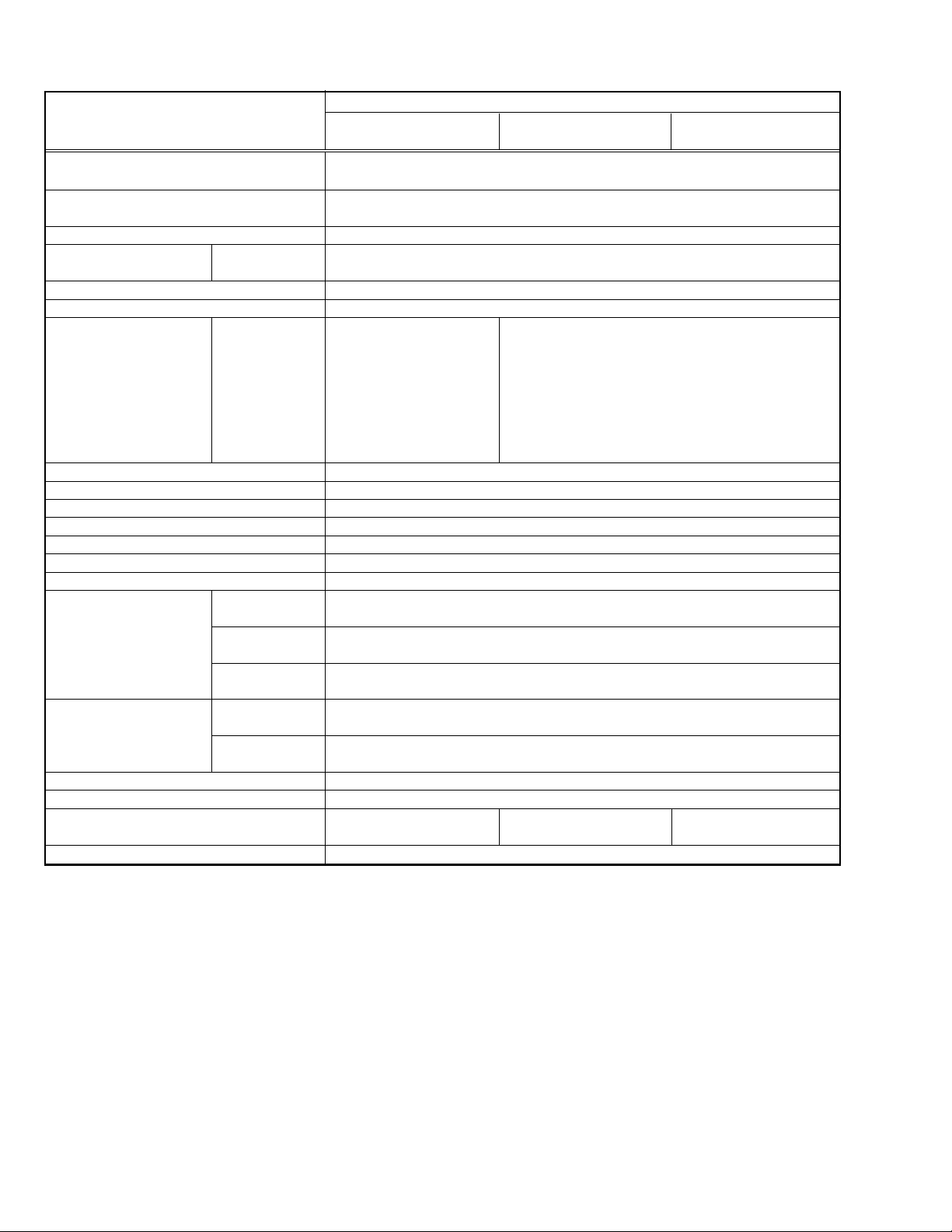
SPECIFICATION
Contents
Items
Dimentions (W x H x D) 46.5cm x 32.5cm x 7.8cm (TV only)
Mass 6.1kg (TV only)
TV RF System B, G, I, D, K, L
Colour System TV Mode PAL / SECAM
Video Mode PAL / SECAM / NTSC3.58 / NTSC4.43
Stereo System A2(B/G, D/K), NICAM (B/G, I, D/K, L)
Teletext System FLOP(Fastext), TOP, WST(World Standard System)
Receiving Frequency E2 ~ E12, E21 ~ E69 E21 ~ E69
ITALY A-H, H+1, H+2
IR A ~ J A ~ J
French cable TV 116MHz ~ 172MHz
Aerial Input Terminal 75Ω unbalanced
Power Input TV : 12V DC, AC adapter : AC100V ~ AC240V, 50Hz/60Hz
Power Consumption 60W, Standby : 6W
Display area Visible size: 43.5cm (Diagonal) / 37.0cm x 22.5cm (H x V)
Display pixels 1280 x 768 (W-XGA)
Speakers 5.4cm, Round type x 2
Audio Output 3W + 3W
Video / Audio Inputs EXT-1 terminal Euroconnector (21pin SCART)
(1/2/3) Composite video, RGB, Audio L, R
EXT-2 terminal Euroconnector (21pin SCART)
EXT-3 terminal RCA connectors x3, S-VIDEO connector x1
Video / Audio Outputs EXT-1 terminal Euroconnector (21pin SCART)
Audio RCA connectors x3
PC Input Analog RGB : D-SUB(15pin) x1, PC AUDIO IN x1
Headphone 3.5mm stereo mini jack x 1
Remote Control Unit DA-5000100084 DA-5000100085 DA-5000100084
AC adapter HP-OL060D03
LT-17E31 BUG LT-17E31 BJG LT-17E75 BJG
LT-17E31 SUG LT-17E31 SJG LT-17E75 SJG
46.5cm x 36.3cm x 19.0cm
7.3kg
S1 ~ S41, X, Y, Z, Z+1, Z+2
F2 ~ F10, F21 ~ F69
R1 ~ R12, R21 ~ R69
220MHz ~ 469MHz
Composite video, S-VIDEO, RGB, Audio L, R
Composite video, S-VIDEO, Audio L, R
Composite video, Audio L, R (TV broadcast outputs)
Audio L, R, Subwoofer
(AA/R06/UM-3 battery x 2) (AA/R06/UM-3 battery x 2) (AA/R06/UM-3 battery x 2)
NOTE: Design & specifications are subject to change without notice.
1-2 (No. YA031)
Page 4

SECTION 1
PRECAUTION
1. 1 SAFETY PRECAUTIONS
(1) The design of this product contains special hardware,
many circuits and components specially for safety
purposes. For continued protection, no changes should
be made to the original design unless authorized in writing
by the manufacturer. Replacement parts must be identical
to those used in the original circuits. Service should be
performed by qualified personnel only.
(2) Alterations of the design or circuitry of the products should
not be made. Any design alterations or additions will void
the manufacturer's warranty and will further relieve the
manufacturer of responsibility for personal injury or
property damage resulting therefrom.
(3) Many electrical and mechanical parts in the products have
special safety-related characteristics. These
characteristics are often not evident from visual inspection
nor can the protection afforded by them necessarily be
obtained by using replacement components rated for
higher voltage, wattage, etc. Replacement parts which
have these special safety characteristics are identified in
the parts list of Service manual. Electrical components
having such features are identified by shading on the
schematics and by () on the parts list in Service
manual. The use of a substitute replacement which does
not have the same safety characteristics as the
recommended replacement part shown in the parts list
of Service manual may cause shock, fire, or other hazards.
(4) Don't short between the LIVE side ground and ISOLATED
(NEUTRAL) side ground or EARTH side ground when
repairing.
Some model's power circuit is partly different in the GND.
The difference of the GND is shown by the LIVE : (
GND, the ISOLATED (NEUTRAL) : (
EARTH : (
) side GND. Don't short between the LIVE
) side GND and
side GND and ISOLATED (NEUTRAL) side GND or EARTH
side GND and never measure the LIVE side GND and
ISOLATED (NEUTRAL) side GND or EARTH side GND at
the same time with a measuring apparatus (oscilloscope
etc.).
If above note will not be kept, a fuse or any parts will be
broken.
(5) If any repair has been made to the chassis, it is
recommended that the B1 setting should be checked or
adjusted (See ADJUSTMENT OF B1 POWER SUPPLY).
(6) The high voltage applied to the picture tube must conform
with that specified in Service manual. Excessive high
voltage can cause an increase in X-Ray emission, arcing
and possible component damage, therefore operation
under excessive high voltage conditions should be kept
to a minimum, or should be prevented. If severe arcing
occurs, remove the AC power immediately and determine
the cause by visual inspection (incorrect installation,
cracked or melted high voltage harness, poor soldering,
etc.). To maintain the proper minimum level of soft X-Ray
emission, components in the high voltage circuitry
including the picture tube must be the exact replacements
or alternatives approved by the manufacturer of the
complete product.
) side
(8) When service is required, observe the original lead dress.
Extra precaution should be given to assure correct lead
dress in the high voltage circuit area. Where a short circuit
has occurred, those components that indicate evidence
of overheating should be replaced. Always use the
manufacturer's replacement components.
(9) Isolation Check
(Safety for Electrical Shock Hazard)
After re-assembling the product, always perform an
isolation check on the exposed metal parts of the cabinet
(antenna terminals, video/audio input and output
terminals, Control knobs, metal cabinet, screw heads,
earphone jack, control shafts, etc.) to be sure the product
is safe to operate without danger of electrical shock.
a) Dielectric Strength Test
The isolation between the AC primary circuit and all metal
parts exposed to the user, particularly any exposed metal
part having a return path to the chassis should withstand
a voltage of 3000V AC (r.m.s.) for a period of one second.
(. . . . Withstand a voltage of 1100V AC (r.m.s.) to an
appliance rated up to 120V, and 3000V AC (r.m.s.) to an
appliance rated 200V or more, for a period of one second.)
This method of test requires a test equipment not generally
found in the service trade.
b) Leakage Current Check
Plug the AC line cord directly into the AC outlet (do not use
a line isolation transformer during this check.). Using a
"Leakage Current Tester", measure the leakage current
from each exposed metal part of the cabinet, particularly
any exposed metal part having a return path to the chassis,
to a known good earth ground (water pipe, etc.). Any
leakage current must not exceed 0.5mA AC (r.m.s.).
However, in tropical area, this must not exceed 0.2mA AC
(r.m.s.).
Alternate Check Method
Plug the AC line cord directly into the AC outlet (do not
use a line isolation transformer during this check.).
Use an AC voltmeter having 1000 ohms per volt or
more sensitivity in the following manner. Connect a
1500Ω 10W resistor paralleled by a 0.15µF AC-type
capacitor between an exposed metal part and a known
good earth ground (water pipe, etc.). Measure the AC
voltage across the resistor with the AC voltmeter. Move
the resistor connection to each exposed metal part,
particularly any exposed metal part having a return path
to the chassis, and measure the AC voltage across
the resistor. Now, reverse the plug in the AC outlet and
repeat each measurement. Any voltage measured
must not exceed 0.75V AC (r.m.s.). This corresponds
to 0.5mA AC (r.m.s.).
However, in tropical area, this must not exceed 0.3V AC
(r.m.s.). This corresponds to 0.2mA AC (r.m.s.).
AC VOLTMETER
(HAVING 1000Ω/V,
OR MORE SENSITIVITY)
0.15µF AC-TYPE
(7) Do not check high voltage by drawing an arc. Use a high
voltage meter or a high voltage probe with a VTVM.
Discharge the picture tube before attempting meter
connection, by connecting a clip lead to the ground frame
and connecting the other end of the lead through a 10kΩ
2W resistor to the anode button.
GOOD EARTH GROUND
1500Ω 10W
PLACE THIS PROBE
ON EACH EXPOSED
ME TA L PA RT
(No. YA031) 1-3
Page 5

1.2 INSTALLATION
1.2.1 HEAT DISSIPATION
If the heat dissipation vent behind this unit is blocked, cooling efficiency may deteriorate and temperature inside the unit will rise.
Therefore, please make sure pay attention not to block the heat dissipation vent as well as the ventilation outlet behind the unit
and ensure that there is room for ventilation around it.
1.2.2 INSTALLATION REQUIREMENTS
Ensure that the minimal distance is maintained, as specified below, between the unit with and the surrounding walls.
Install the unit on stable flooring or stands.
Take precautionary measures to prevent the unit from tipping in order to protect against accidents and earthquakes.
Distance recommendations
Avoid improper installation and never position the unit where good ventilation
is impossible.
150 mm
200 mm 200 mm
150 mm
When installing this TV, distance recommendations must be maintained
between the set and the wall, as well as inside a tightly enclosed area or
50 mm
piece of furniture.
Keep to the minimum distance guidelines shown for safe operation.
1.3 PRECAUTIONS
(1) Depending on the around temperature, the brightness leaning occurs. Be careful of the environment in the product
installation place and so on sufficiently.
(2) Don't hinder radiation from the back, the heaven and the side. Please refer to the next page that explains about the
condition of the installation.
The inside becomes hot if hindering radiation and there is fear, which the inner circuit damages.
(3) Install in the place with good ventilation. Use in the condition that around temperature is in the 0~35°C range.
(4) Avoid preservation and use at the high temperature or high humidity place. If you behave like this, leaning sometimes
happens in the screen when the set actives.
(5) Depending on the condition and the environment of display, the slight fleck of the light and leaning of the screen and so on
is sometimes conspicuous. This is the characteristic which is peculiar to liquid crystal display. It is not set trouble.
(6) This monitor has cool cathode pipe as the backlight. The time change and the use time sometimes change brightness
and condition of display.
1.4 THE ATTENTION IN TRANSPORTATION
When transporting a set, if the load handling is bad (throwing, falling and so on) however it is using a solid box, pressure inside
liquid crystal display.
In the case there is fear to break the liquid crystal display while transporting. To prevent from the accident or trouble while
transporting, pay attention to choice of the transportation company sufficiently and also arrange for it in the delivery after the
attention of the load handling is explained to the transportation company.
This set is used glass for composing liquid crystal display. When carrying, pay attention not to add over vibration and impact
sufficiently.
Ensure that it is placed upright and not horizontally during transportation and storage as the LCD panel is very vulnerable to
lateral impacts and may break. During transportation, ensure that the unit is loaded along the traveling direction of the vehicle,
and avoid stacking them on one another. For storage, ensure that they are stacked in 2 layers or less even when placed upright.
1-4 (No. YA031)
Page 6

SECTION 2
SPECIFIC SERVICE INSTRUCTIONS
2.1 DESCRIPTION ABOUT LIQUID CRYSTAL PANEL
2.2.1 STRUCTURE OF LIGUID CRYSTAL PANEL
The Liquid Crystal Panel of this model is TFT Panel. The Print circuit board that consist of TFT array and the print circuit board
adopted stripe shaped image element alignment are used. These two boards are mixed. The Liquid crystal is enclosed between
two boards.
2.1.2 LONG RANGE AFTERIMAGE OF LIQUID CRYSTAL
The small amount of ion material has mixed a liquid crystal panel with the liquid crystal material in the manufacturing process.
If ion material is piled up partially among the poles when the voltage is impressed among the poles, the brightness difference
occurs and becomes a long-range afterimage If same picture is reflected for long time, such a long-range afterimage occurs. If
the long-range afterimage occurs, we recommend that you reflect the single color image or moving picture and so on to restore.
2.1.3 THE DISPLAY REPLYING SPEED OF LIQUID CRYSTAL
Because the speed to display of Liquid crystal panel is slower than the speed of the CRT monitor, some of the moving picture
cannot overtake to the speed to display and the image looks flowing is sometimes displayed. This is not trouble, but efficiency
of Liquid Crystal.
2.1.4 THE EYESIGHT CORNER OF LIQUID CRYSTAL
The liquid crystal panel has the wide eyesight corner for which it is difficult to reverse brightness. The tint changes depending on
the direction to see a screen. This is not trouble, but efficiency of Liquid Crystal.
2.1.5 THE PICTURE ELEMENT FAULT OF LIQUID CRYSTAL
The liquid crystal panel is composed of precise technique but all devices don't always work right.
2.2 ATTENTION ITEMS WHEN REPLACING PARTS
2.2.1 ATTENTION TO EXCHANGE THE LIQUID CRYSTAL PANEL
(1) The stillness electricity sometimes makes damage a liquid crystal panel. In liquid crystal panel exchange, do a measure
of the stillness electricity such as the earth band.
(2) A liquid crystal panel and back-light are made from glass. If you gain an impact to these materials, there is fear to damage.
So in case of treatment, be careful sufficiently.
(3) Fix with the screw after confirming that there is not a float to chassis base when exchanging liquid crystal panel.
After that reflect all the black signals and confirm that brightness leaning doesn't occur near the screw fixation part.
When brightness leaning occurs, slacken a screw in the neighborhood until the brightness leaning is running-out.
(4) Fix the torque that installs a screw below 0.294Nm.
If you install at any more torque, the liquid crystal panel is transformed and sometimes damages.
(5) If you pull out or insert each connector when power is ON, it causes the trouble.
So pull out or insert each connector in the condition to have pulled out a power supply plug.
2.2.2 ATTENTION WHEN EXCHANGING THE FUSE
When exchanging the fuse, please use specified parts. After fuse exchange, confirm that insulater is set to the shield and
insulate surely.
(No. YA031) 1-5
Page 7
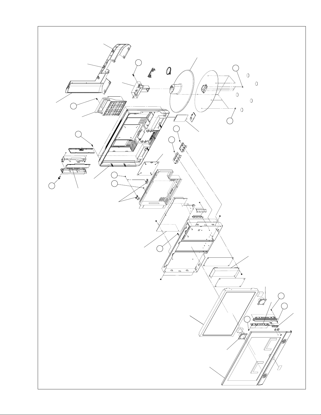
SECTION 3
DISASSEMBLY
3.1 DISASSEMBLY PROCEDURE
CAUTION:
• Disconnect the set and attached devices from the electrical outlet
• To avoid ESD (Electro-Static Discharge), ground yourself by using a wrist grounding strap or by periodically touching
unpainted metal on the set.
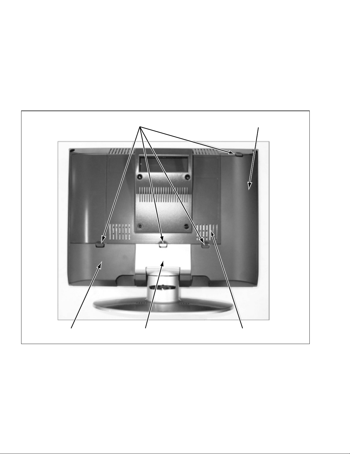
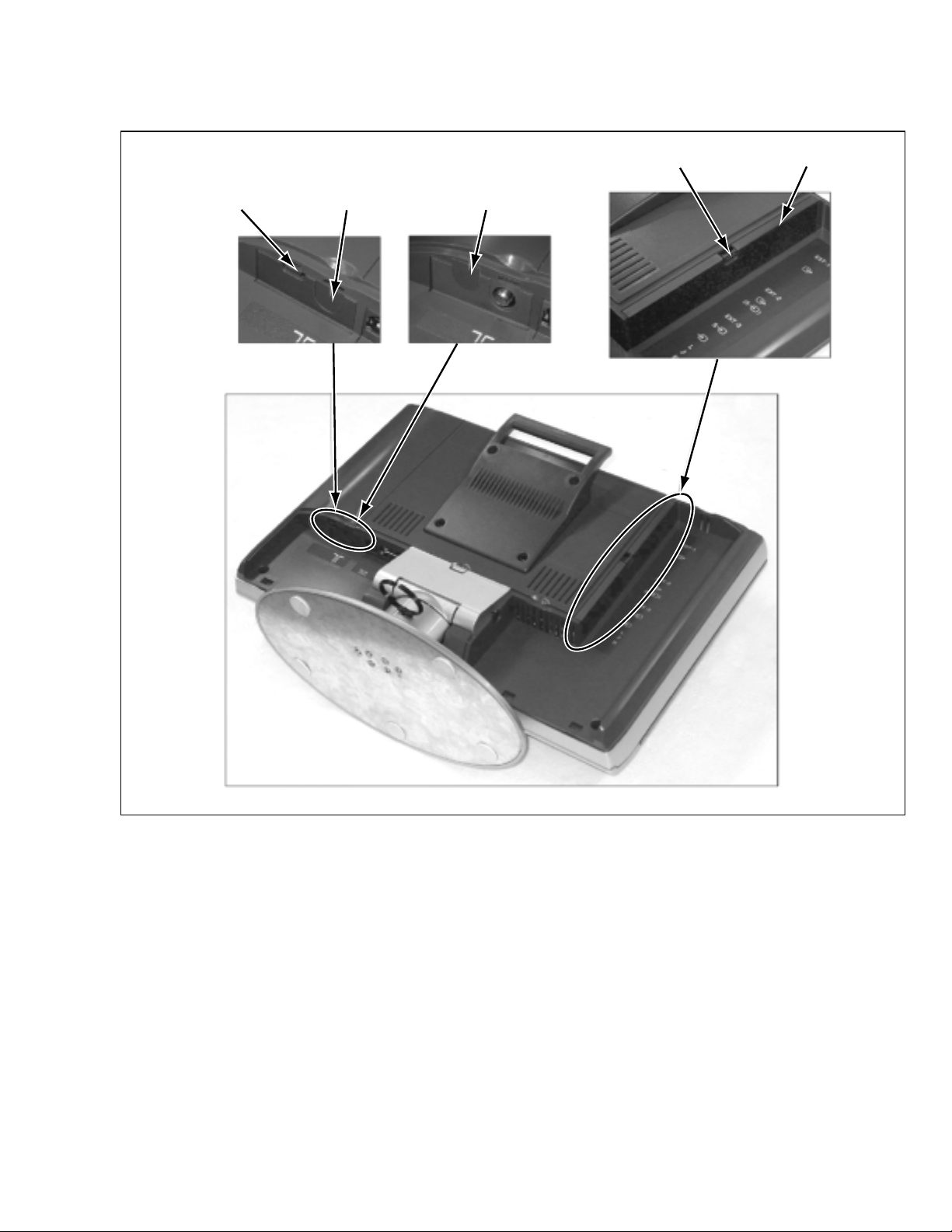
3.1.1 REMOVING THE CABLE COVER AND NECK COVER
(1) Remove the CABLE COVER (L) by pulling the snap tabs.
(2) Make similar ways to remove the CABLE COVER (R) and NECK COVER.
Snap tabs
CABLE COVER (L)
CABLE COVER (R) NECK COVER REAR COVER
1-6 (No. YA031)
Page 8
3.1.2 REMOVING THE DUMMY COVERS (If necessary)
(1) Remove the DUMMY COVERS of TUNER module and AV JACK module by pulling the snap tabs
Snap tab DUMMY COVER
Snap tab DUMMY COVER TUNER COVER
TUNER module
AV JACK module
(No. YA031) 1-7
Page 9
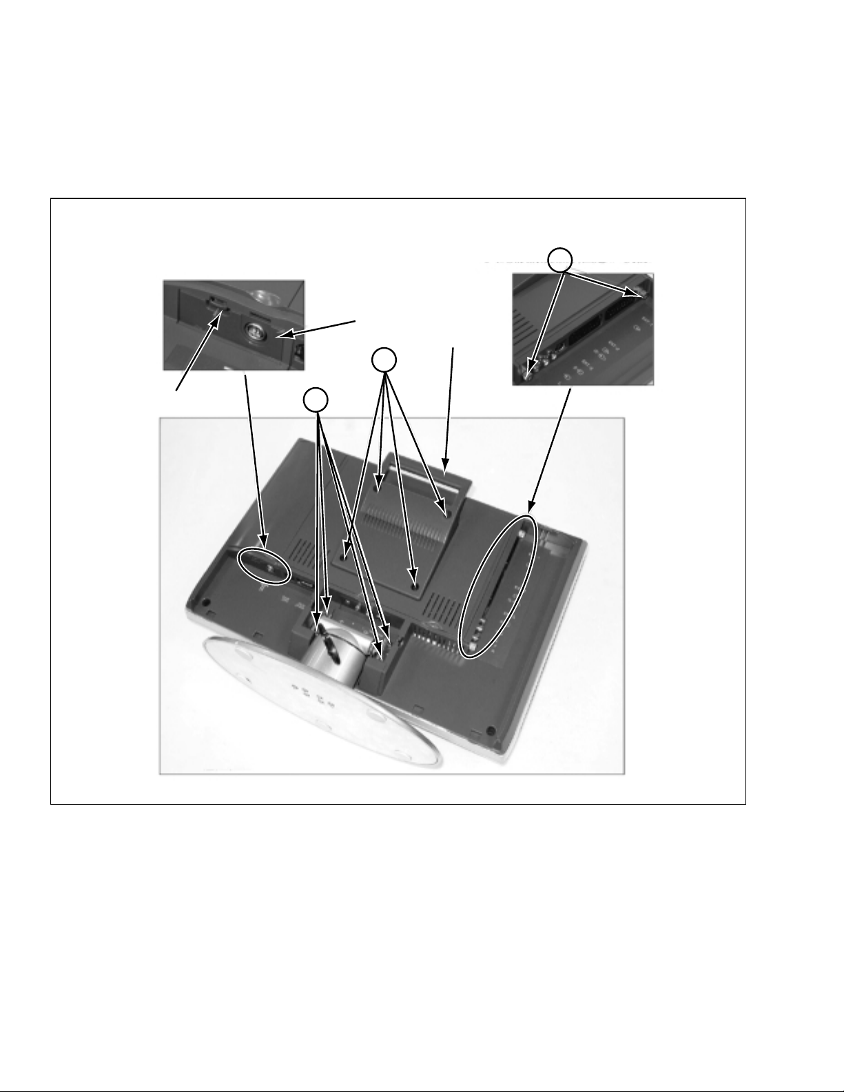
3.1.3 PREPARING TO REMOVE THE MODULE UNITS
(1) Remove the TUNER module cover by pulling snap tab.
(2) Loosen 2 screws [A] of AV JACK module.
3.1.4 REMOVING THE BASE AND THE HANDLE
(1) Remove 4 screws [B] and remove the BASE by pulling BASE.
(2) Remove 4 screws [C] and remove the HANDLE.
TUNER module
C
A
HANDLE
Snap tab
B
1-8 (No. YA031)
Page 10
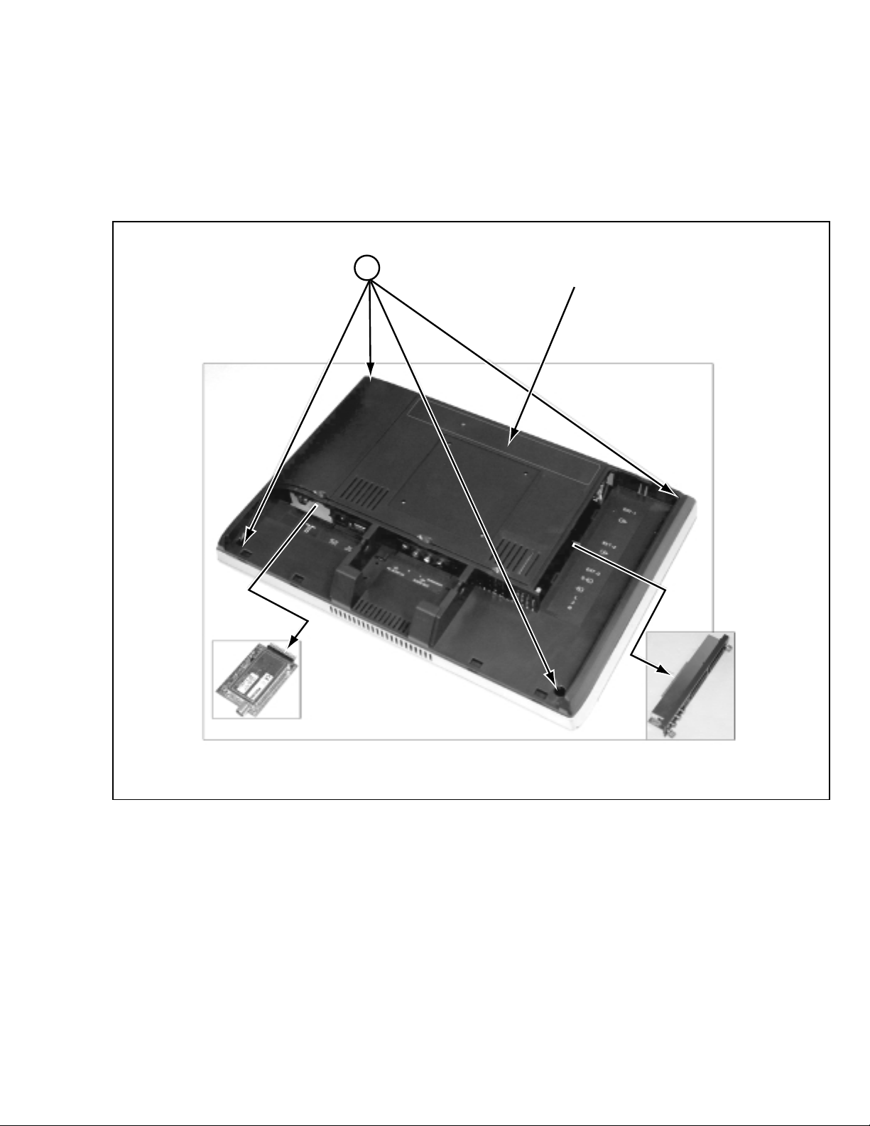
3.1.5 REMOVING THE MODULE UNITS
(1) Remove the TUNER module by pulling carefully.
(2) Remove the AV JACK module by pulling carefully.
3.1.6 REMOVING THE REAR COVER
(1) Remove 4 screws [D] and remove the REAR COVER.
NOTE:
For the REAR COVER is attached tightly, it is easy to open from the corner of the REAR COVER.
D
REAR COVER
TUNER module
AV JACK module
(No. YA031) 1-9
Page 11
3.1.7 REMOVING THE D-SUB COVER AND THE AUDIO COVER
(1) Remove a screw [E] and remove the D-SUB COVER.
(2) Remove a screw [F] and remove the AUDIO COVER.
3.1.8 REMOVING THE MODULE BRACKETS
(1) Remove the 2 screws [G] and remove the MODULE BRACKETS.
MODULE BRACKETS
G
1-10 (No. YA031)
D-SUB COVER
E
AUDIO COVER
F
Page 12
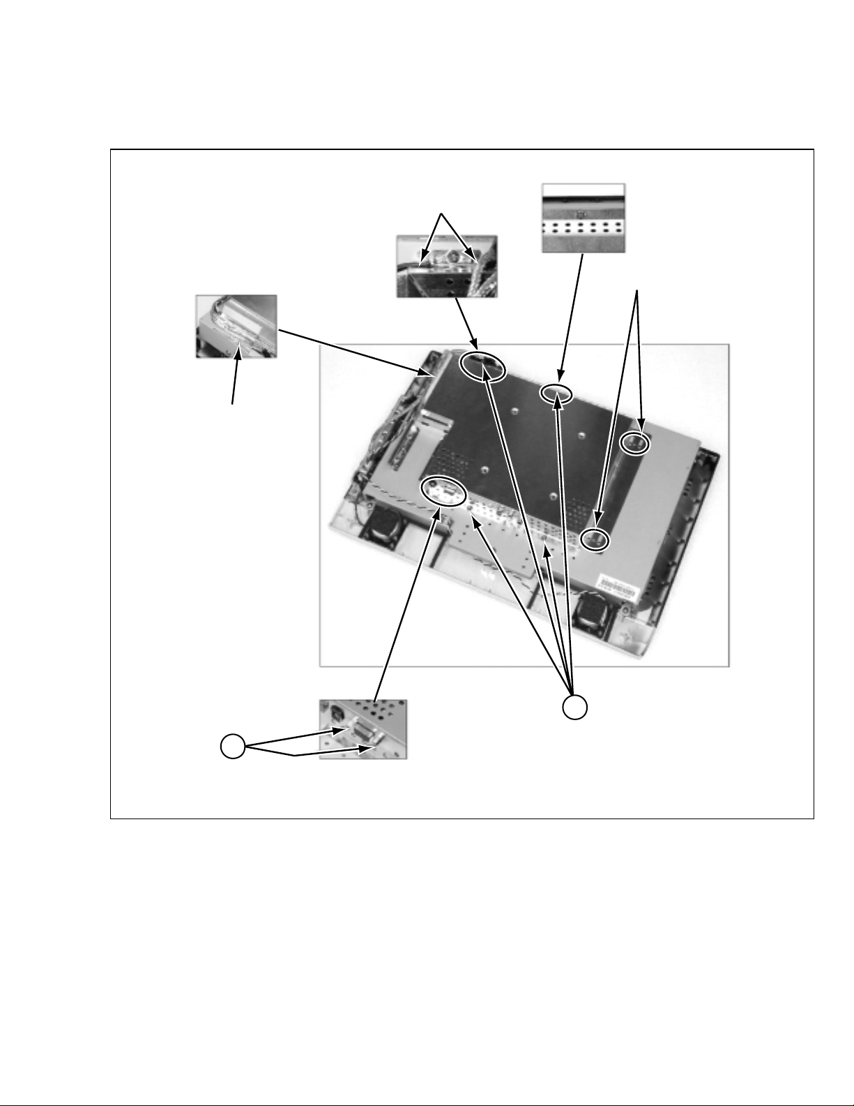
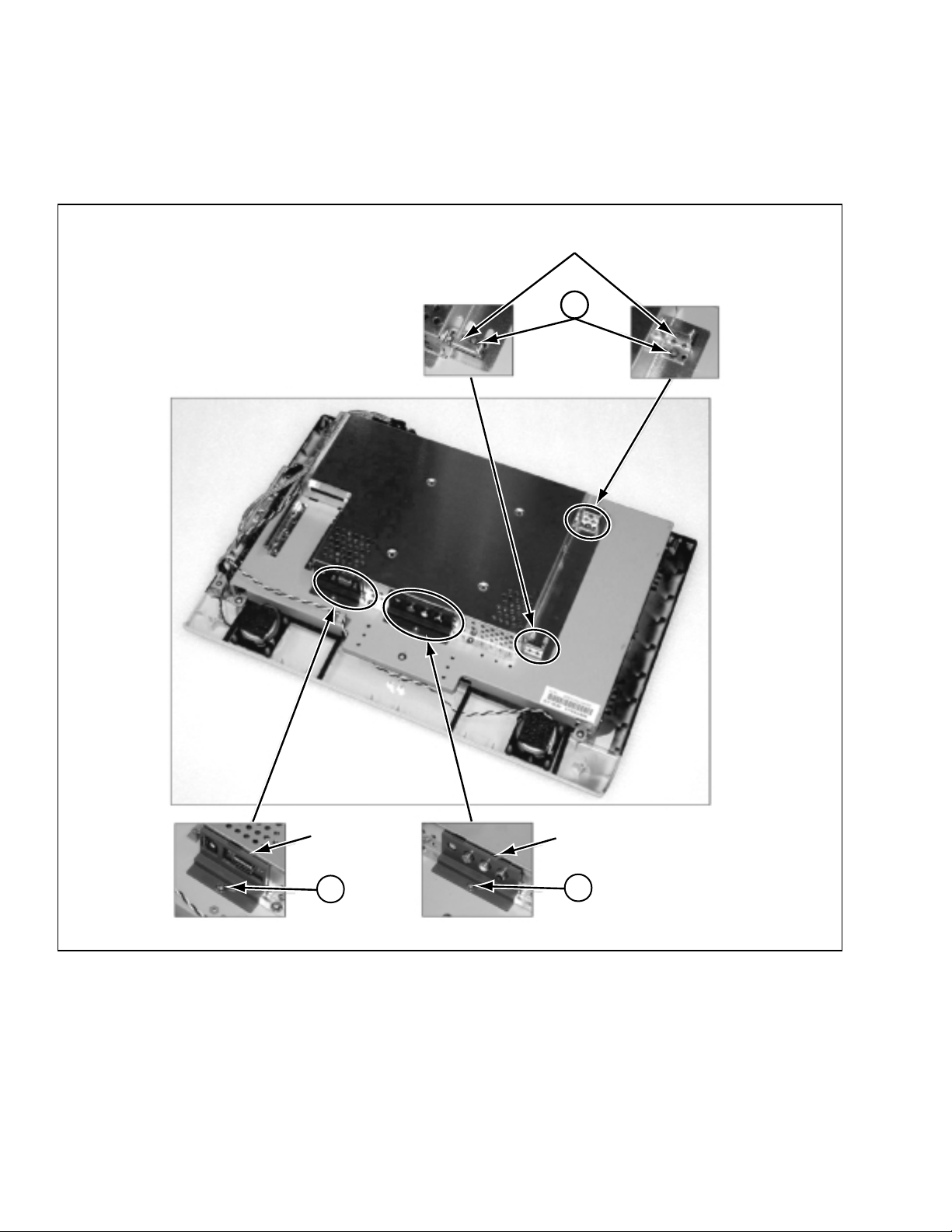
3.1.9 REMOVING THE MAIN BOARD SHIELD
(1) Remove 4 screws [H] and remove the 2 nuts [I].
(2) Remove the tape fixing wires.
(3) Remove the MAIN BOARD SHIELD by sliding to downside and lifting.
Release the earth wires
Tape
Holes for slide
H
I
(No. YA031) 1-11
Page 13
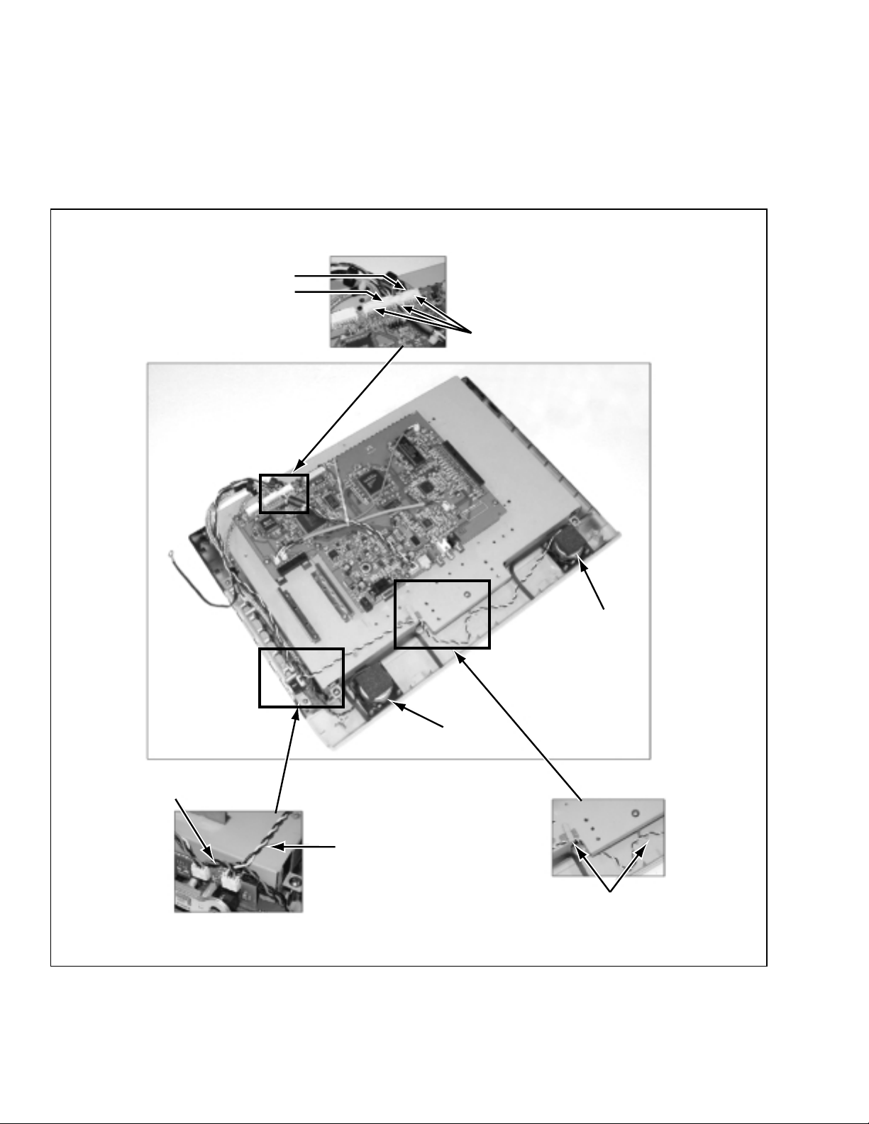
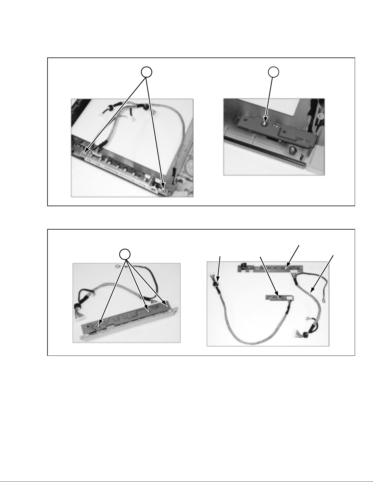
3.1.10 DISCONNECTING THE WIRING CONNECTORS
(1) Disconnect the wiring connectors from P002 and P003 on MAIN PWB.
NOTES:
Confirm the wiring layout of harnesses.
• The AUDIO wires are fixed by hot bond between P002 and P003, after connected.
• The RIGHT SPEAKER wires are turn around into the gap as shown Fig.A.
• The LEFT SPEAKER wires must be put away from the top of the RIGHT SPEAKER and hooked as shown Fig. B.
P003
P002
Fixed by hot bond
Wire for SPEAKER (R)
SPEAKER (L)
SPEAKER (R)
Wire for SPEAKER (L)
Hooks
Fig. BFig. A
1-12 (No. YA031)
Page 14
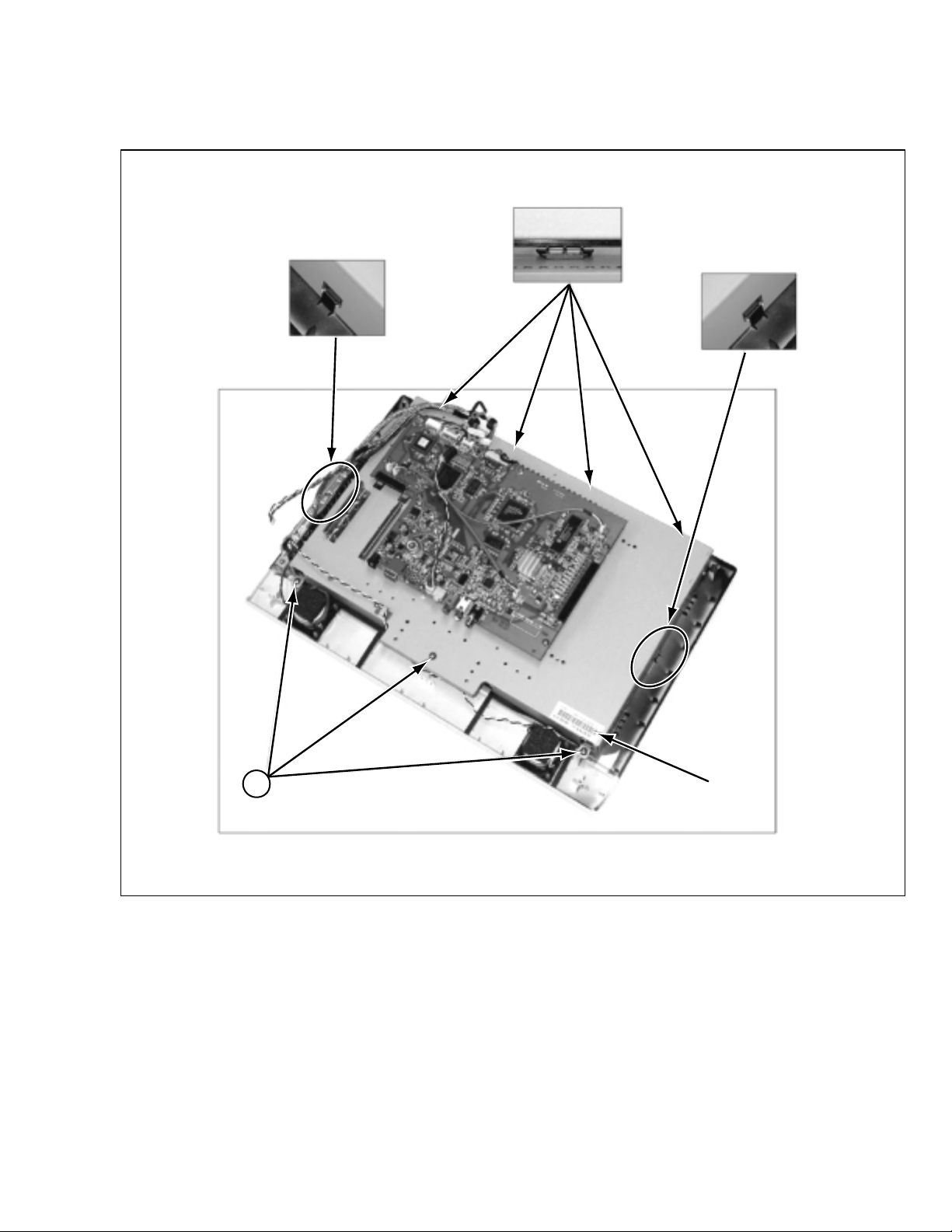
3.1.11 REMOVING THE LCD MODULE ASS’Y
(1) Remove 3 screws [J].
(2) Remove the LCD MODULE ASS’Y by release from the 6 latches.
Latches (Top) x4
Latch (Right)
Latch (Left)
J
Label
(No. YA031) 1-13
Page 15
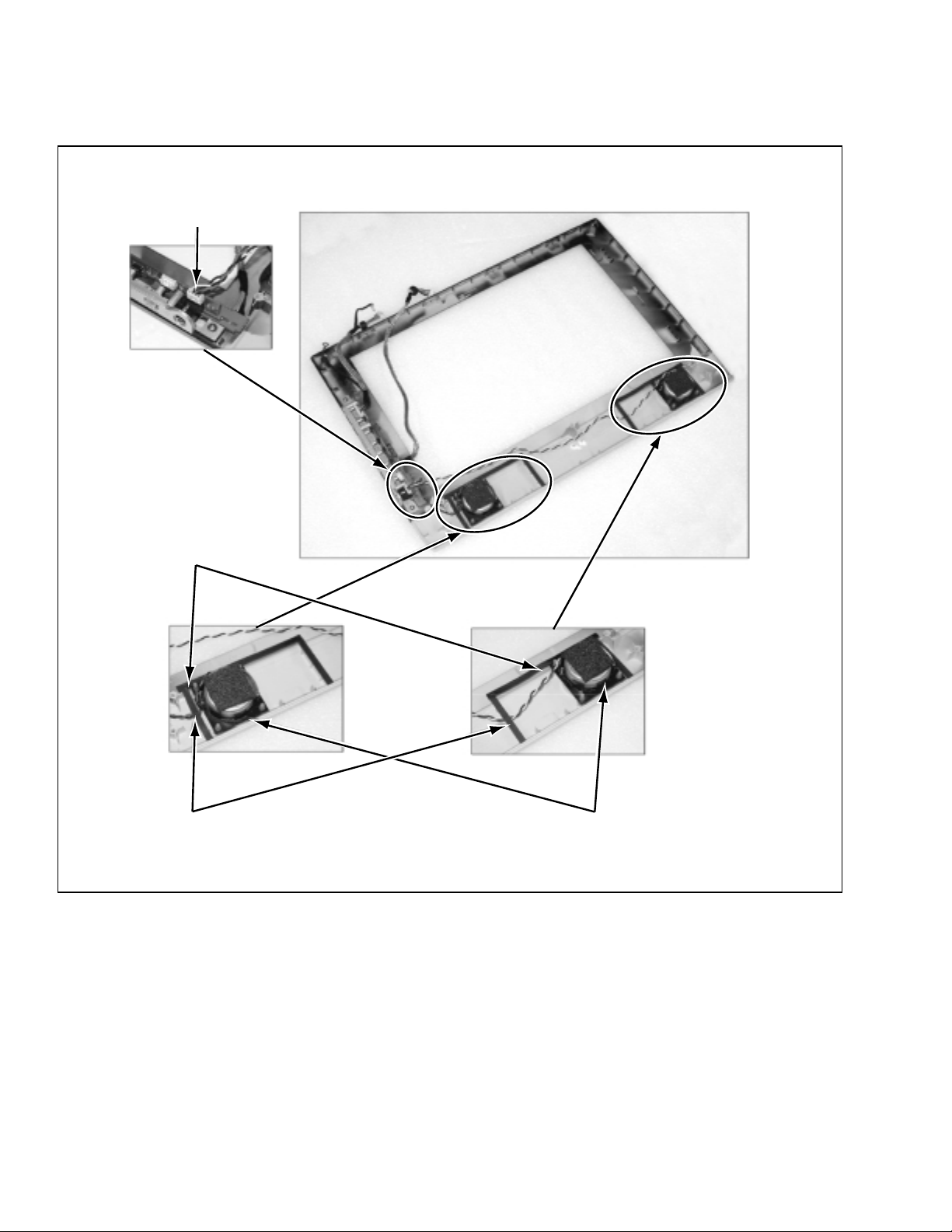
3.1.12 REMOVING THE SPEAKERS
(1) Disconnect the wires from the P603 on FRONT CONTROL PWB.
(2) Strip off the sponges and lift the SPEAKERS.
P603
Sponges
Wires under sponges
SPEAKERS
1-14 (No. YA031)
Page 16
3.1.13 REMOVING THE FRONT CONTROL PWB AND IR SENSOR PWB
(1) Remove 2 screws [K] and remove the FRONT CONTROL PWB.
(2) Remove a screw [L] and remove the IR SENSOR PWB.
K L
(3) Remove 3 screws [M] and remove the KEY assembly.
M
FRONT CONTROL PWB
wires (8P)IR SENSOR PWB wires (6P)
(No. YA031) 1-15
Page 17
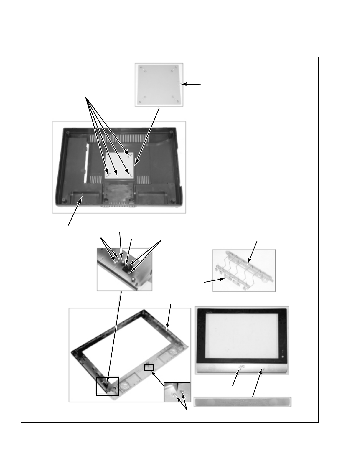
3.1.14 SUPPLEMENTAL 1
• The below assemblies are welded process.
• If removing these components, it is necessary to replace them.
Welded
VESA BRACKET
REAR COVER
Welded
LED WINDOW
IR LENS
Welded
FRONT COVER
KEY COVER
KEY
LOGO
1-16 (No. YA031)
Welded
Page 18
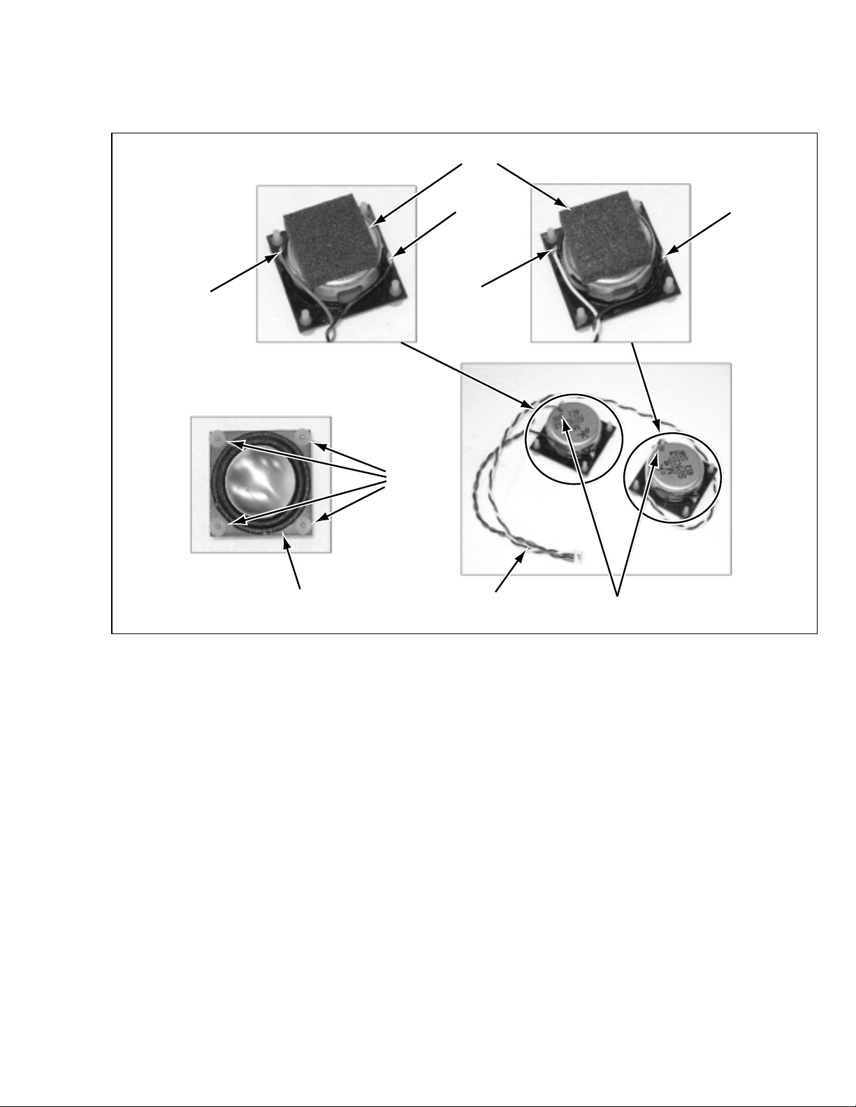
3.1.15 SUPPLEMENTAL 2
• SPEAKER assembly.
• Confirm to connect the positive wire to the terminal with RED marker.
High density rubber
Red (+)
Black ( - )
White (+)
Cushion
rubber
SPEAKER SPEAKER wires
Black ( - )
RED marker
(No. YA031) 1-17
Page 19
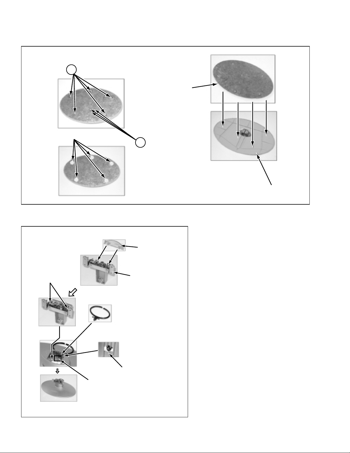
3.1.16 SUPPLEMENTAL 3
• BASE assembly.
P
Rubber foot
BASE BRACKET
Q
BASE
• HINGE assembly.
Latchs
HINGE COVER
HINGE
Hot bond
Insert until locking
1-18 (No. YA031)
Page 20
C
CABLE COVER (R)
NECK COVER
B
BASE
Q
HINGE
CABLE COVER (L)
HANDLE
D
A
AV JACK PWB
REAR COVER
G
H
MODULE BRACKET
MAIN PWB
P
E
F
TUNER PWB
VESA BRACKET
J
INVERTER
LCD PANEL
SPEAKER
K
FRONT CONTROL PWB
L
IR SENSOR PWB
M
SPEAKER
FRONT COVER
(No. YA031) 1-19
Page 21
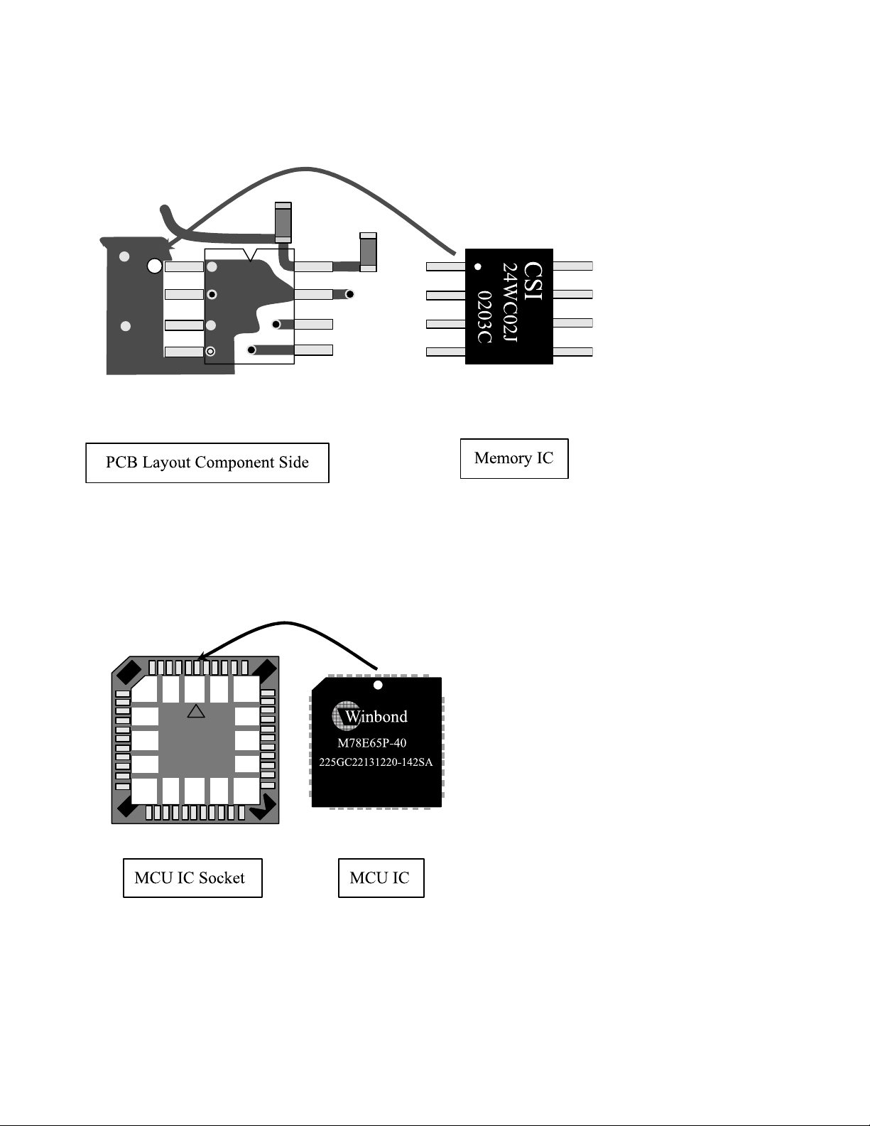
3. 2 REPLACEMENT OF MEMORY IC
3.2.1 PROCEDURE FOR REPLACING OF MEMORY IC
Memory IC Notice
MCU IC Notice
1-20 (No. YA031)
Page 22
3.3 REPLACEMENT OF CHIP COMPONENT
A
B
C
3.3.1 CAUTIONS
(1) Avoid heating for more than 3 seconds.
(2) Do not rub the electrodes and the resist parts of the pattern.
(3) When removing a chip part, melt the solder adequately.
(4) Do not reuse a chip part after removing it.
3.3.2 SOLDERING IRON
(1) Use a high insulation soldering iron with a thin pointed end of it.
(2) A 30w soldering iron is recommended for easily removing parts.
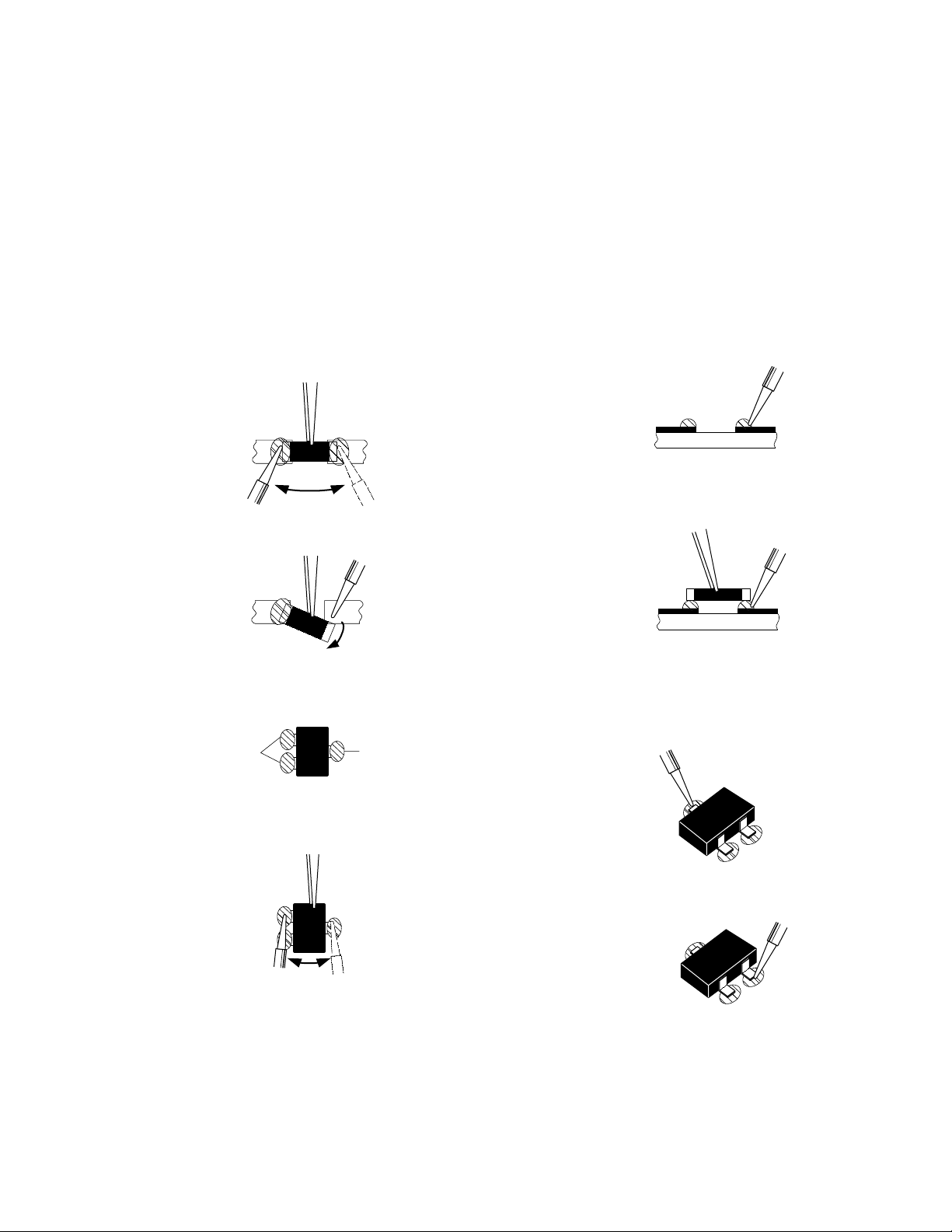
3.3.3 REPLACEMENT STEPS
1. How to remove Chip parts
[Resistors, capacitors, etc.]
(1) As shown in the figure, push the part with tweezers and
alternately melt the solder at each end.
(2) Shift with tweezers and remove the chip part.
2. How to install Chip parts
[Resistors, capacitors, etc.]
(1) Apply solder to the pattern as indicated in the figure.
(2) Grasp the chip part with tweezers and place it on the
solder. Then heat and melt the solder at both ends of
the chip part.
[Transistors, diodes, variable resistors, etc.]
(1) Apply extra solder to each lead.
SOLDER
SOLDER
(2) As shown in the figure, push the part with tweezers and
alternately melt the solder at each lead. Shift and remove
the chip part.
Note :
After removing the part, remove remaining solder from
the pattern.
[Transistors, diodes, variable resistors, etc.]
(1) Apply solder to the pattern as indicated in the figure.
(2) Grasp the chip part with tweezers and place it on the
solder.
(3) First solder lead A as indicated in the figure.
(4) Then solder leads B and C.
A
B
C
(No. YA031) 1-21
Page 23

SECTION 4
ADJUSTMENT
This service manual does not describe ADJUSTMENT.
1-22 (No. YA031)
Page 24
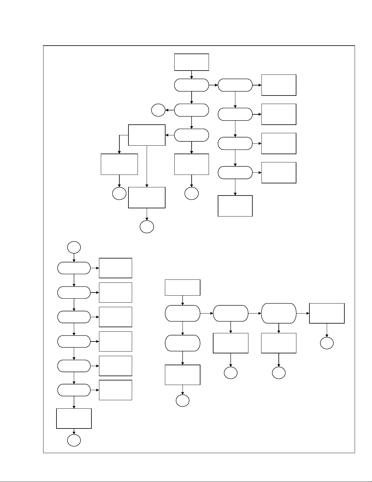
SECTION 5
TROUBLESHOOTING
No picture Appear
Next
Picture
shows
MCU (I004) Hangs
End
Next
Reset the MCU(I004)
by pushing the power
key or replugging the
DC 12V cable
Still no
Picture
Replace I004
End
Does the LED
light up
No
LED display is
amber
No
Is it entering into
power saving mode
Restart PC signal
to ensure H. V.
sync are not
absent
End
Ye s
Ye s
Ye s
No
The Vo ltage of
L100;L083 is 12V
The Vo ltage of
I041 #6 is 12V
The Vo ltage of
The Vo ltage at #44
Ye s
Ye s
L041#2 is 5V
Ye s
of I004 is 5V
Ye s
Replace I004
No
Replace F001
No
Replace L100
& L083
No
Replace I041 & D027
No
Check I004 socket is
loosened
The Vo ltage of I002
#2 is 2.5V
Yes
The Vo ltage of I001
#2 is 3.3V
Yes
The Vo ltage of I003
#2 is 1.8V
Yes
The Vo ltage of I011
#2 is 3.3V
Yes
The Vo ltage of I012
#2 is 3.3V
Yes
The Vo ltage of I017
#2 is 3.3V
Yes
Replace I034
(TP6760)
End
No
No
No
No
No
No
Replace I002
Replace I001
Replace I003
Replace I011
Replace I012
Replace I017
The Ve r. Or Hor.
Sync. Does not hold
Are the output of
TP6760(CLK,H,V ,
DE) normal
Are the input
waveforms of
TP6760 normal
Yes
Replace I034
(TP6760)
End
Are flex cable
Yes Y es
attached firmly at
P008
No
Tighten two flex
cables at P008
End
Are flex cable
attached firmly at
the LCD panel
connectors
YesNo
Replace V901 (LCD
panel)
End
No
Tighten flex cable at
P008
End
(No. YA031) 1-23
Page 25

Victor Company of Japan, Limited
AV & MULTIMEDIA COMPANY VIDEO DISPLAY CATEGORY 12, 3-chome, Moriya-cho, kanagawa-ku, Yokohama, kanagawa-prefecture, 221-8528, Japan
(No. YA031)
Printed in Japan
WPC
Page 26
ENGLISH
DEUTSCH
FRANÇAIS
NEDERLANDS
CASTELLANO
LT-17E31 BUG
ITALIANO
PORTUGUÊS
LT-17E31 SUG
LCD FLAT TELEVISION INSTRUCTIONS
LCD-FLACHBILD-FERNSEHER
TELEVISEUR A ECRAN PLAT - LCD
LCD VLAKKE TELEVISIE
TELEVISOR PLANO LCD
BEDIENUNGSANLEITUNG
MANUEL D’INSTRUCTIONS
GEBRUIKSAANWIJZING
MANUAL DE INSTRUCCIONES
TELEVISORE SCHERMO PIATTO LCD
TELEVISÃO DE ECRÃ PLANO DE CRISTAIS LÍQUIDOS
ISTRUZIONI
INSTRUÇÕES
1
Page 27
Thank you for buying this JVC LCD flat television.
To make sure you understand how to use your new TV, please read this manual thoroughly before you begin.
(“LCD” stands for Liquid Crystal Display.)
WARNING: TO PREVENT FIRE OR SHOCK HAZARD, DO NOT EXPOSE THIS APPLIANCE TO RAIN OR
MOISTURE.
WARNING
Always use the provided AC adapter and power cord.
WARNING
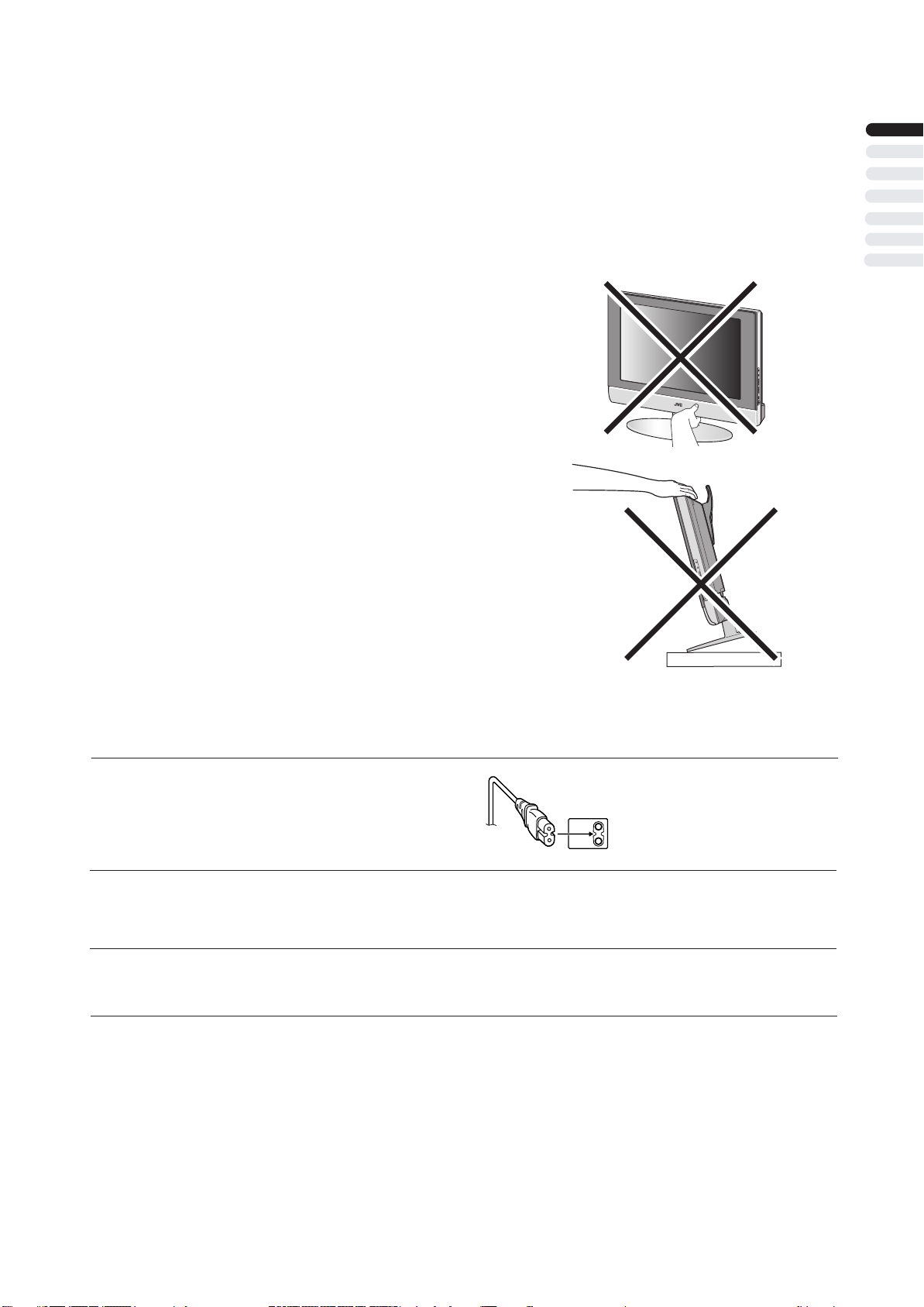
• Fingers may be trapped under the TV causing injuries. Hold the TV at the
bottom in the middle, and do not allow it to tilt up or down.
• The TV may fall causing injuries. Hold the bottom of the stand with your
hand and tilt the TV up and down.
• Do not allow children to hang from the TV, place their elbows on the TV
or lean against the TV. Doing so may cause the TV to fall over and lesd
to injuires.
ENGLISH
CAUTION:
• To avoid electric shock or damage to the unit, first firmly
insert the small end of the power cord into the AC Adpater
unit it is no longer wobbly, and then plug the larger end of
power cord into an AC outlet.
CAUTION:
• Operate only from the power source specified – 240 V,
50/60 Hz) on the AC adapter.
• Avoid damaging the AC plug, AC adapter and power cord.
•
(AC 100 • only
• When you are not using this unit for a long period of time, it is
recommended that you disconnect the power cord from the
main outlet.
CAUTION ON HEATING OF AC ADAPTER:
In using, the AC adapter get heat on the sunface of case.
•
It is normal, not defective. while it is in operation.
• Don't be covered with any material on case of AC adapter
NOTES:
• The rating plate (serial number plate) and safety caution
are on the back of the main unit.
• The rating information and safty causion of the AC Adapter
are on its upper and lower sides.
1
Page 28
Point defects
LCDs use collections of fine pixels to display images. While there is no problem with more than 99.99% of these pixels, please
understand that a very small number of pixels may not light or may light all the time.
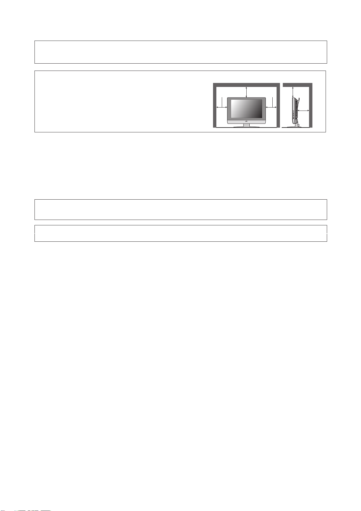
Distance recommendations
Avoid improper installation and never position the unit where good
ventilation is impossible.
When installing this TV, distance recommendations must be maintained
between the set and the wall, as well as inside a tightly enclosed area or
piece of furniture.
150 mm 150 mm
200 mm 2 00 mm
50 mm
Keep to the minimum distance guidelines shown for safe operation.
Failure to take the following precautions may cause damage to the television or remote control.
DO NOT block the TV’s ventilat ion opening s or holes.
(If the ventilation openings or holes are blocked by a newspaper or cloth, etc., the heat may not be able to get out.)
DO NOT place anything on top of the TV.
(such as cosmetics or medicines, flower vases, potted plants, cups, etc.)
DO NOT allow objects or liquid into the cabinet openings.
(If water or liquid is allowed to enter this equipment, fire or electric shock may be caused.)
DO NOT place any naked flame sources, such as lighted candles, on the TV.
DO NOT subject the TV to direct sunlight.
The surface of the TV screen is easily damaged. Be very careful with it when handling the TV.
Should the TV screen become soiled, wipe it with a soft dry cloth. Never rub it forcefully.
Never use any cleaner or detergent on it.
If there is a fault, unplug the unit and call a service technician. Do not attempt to repair it yourself or remove the rear cover and the
AC adapter.
Cleaning the screen
The screen is coated with a special thin film to reduce reflection. If this film is
and other problems that can not be repaired may occur. Pay attention to the following when handling the screen.
• Do not use glue or adhesive tape on the screen.
• Do not write on the screen.
• Do not allow the screen to come in contact with any hard objects.
• Do not allow condensation to form on the screen.
• Do not use alcohol, thinner, benzene or other solvents on the screen.
• Do not rub the screen hard.
da
maged, uneven colors, discoloration, scratches,
2
Page 29

CONTENTS
Setting up your TV..................................4
Installation..........................................................4
Using the stand ..................................................4
Putting the batteries into the Remote control.....5
Remove the terminal cover ................................5
Connecting the aerial and video cassette
recorder (VCR)...................................................6
Connecting the power cord to the AC outlet ......6
Initial settings .........................................7
TV buttons and functions ......................9
Turn the TV on from standby mode ...................9
Choose a TV channel ........................................9
Watch images from external devices .................9
Adjust the volume ..............................................9
Using the Menu..................................................9
Remote control buttons and
functions............................................10
Turn the TV on or off from standby mode........10
Choose a TV channel ......................................10
Adjust the volume ............................................11
Watch images from external equipment ..........11
Displaying the source information .....................11
ZOOM function.................................................12
Sleep timer funtion...........................................13.
Picture mode....................................................13.
Using the PCPIP
Operating a JVC brand VCR or DVD player....14
function
...............................13
Sound setting........................................19
Sound Adjustment........................................... 199
HYPER SOUND
.............................................. 199
FEATURES............................................20
BLUE BACK.................................................... 201
CHILD LOCK................................................... 201
EXT-2 OUTPUT............................................... 200
INSTALL................................................21
MANUAL.......................................................... 213
PROGRAM..................................................... 213
To edit the PROGRAM menu.......................... 224
PC MENU...............................................25
PC PICTURE POSITION................................. 253
PC PICTURE................................................... 253
SOUND............................................................ 254
PC support mode list........................................ 264
Additional preparation.........................27
Connecting external equipment ...................... 278
Troubleshooting...................................29
Specifications.......................................31
ENGLISH
Teletext function...................................15
Basic operation ................................................15
Hold..................................................................15
Sub-page .........................................................16
Reveal..............................................................16
Size ..................................................................16
Index ................................................................16
Cancel..............................................................16
Using the TV’s menu............................17
Basic operation ................................................17
Picture setting.......................................18
PICTURE MODE .............................................18
Picture Adjustment...........................................18
COLOUR TEMP...............................................18
RESET..............................................................18
3
Page 30
Setting up your TV
Installation
Cautions for installation
• Install the TV in a corner on a wall or on the floor so as to keep cords out of the way.
• The TV will generate a slight amount of heat during operation. Ensure that sufficient space is available around the TV to allow
satisfactory cooling. See “Distance recommendations” on page 2.
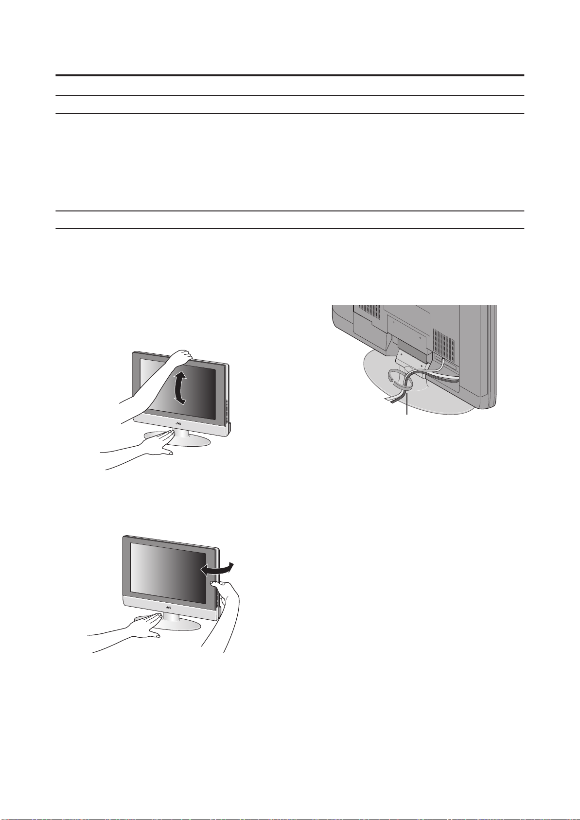
Using the stand
This TV comes with a Table Top Stand already
attached.
This stand can be used to adjust the direction of the TV
screen 5° up, 10° down, and 20° to the left or right.
Tilt the TV up and down:
While holding the bottom of the stand with one hand, use
your other hand to hold the middle of the top of the TV and
slowly tilt the TV up and down.
• As a safety measure, the stand is constructed so that it
requires a certain amount of force to tilt the TV.
Rotate the TV to the left and right:
While holding the bottom of the stand with one hand, use
your other hand to hold the edge of the panel and slowly
adjust the direction of the TV screen.
Cable holder
A cable holder which is used to keep the connection cables
tidy is attached to the back of the stand.
cable holder
4
Page 31

Setting up your TV
Putting the batteries into the Remote control
Use two AA/R6 dry cell batteries.
Insert the batteries from the - end, making sure the + and - polarities are correct.
• Follow the warnings printed on the batteries.
• Battery life is about six months to one year, depending on your frequency of use.
• The batteries we supply are only for setting up and testing your TV, please replace them as soon as you need to.
• If the remote control does not work properly, replace the batteries.
Remove the terminal cover
There are connection terminals behind the covers of the rear of the TV. Remove the cover before
connecting a DVD or VCR.
The covers can be removed by removing the hook at the top and then pulling out while lifting slightly. To replace the covers,
first connect the hook at the bottom of the cover to the TV and then insert the hook at the top.
• Leave the covers off if they do not fit properly. Do not force to replace the covers. Doing so may cause damages of the
connection cables and the covers.
• Leave these covers off when mounting the TV on a wall.
ENGLISH
• 100mm mount based on VESA regulation is equipped.
• The handle and the stand can be left by loosing the screws with a screwdriver when mounting the TV on a wall.
• Spread a soft cloth on a flat table and then place the TV on the cloth with the screen facing downwards when you leave the
handle and the stand.
5
Page 32

Setting up your TV
Connecting the aerial and video
cassette recorder (VCR)
• The connectin
• For further details, refer to the manuals provided with
the devices to be connected.
If you are connecting a VCR, follow
in the diagram below.
If you are not connecting a VCR, follow .
• You can watch a video using the VCR without doing .
For details, see your VCR instruction manual.
• To connect the PC, please see "Connecting the PC"
on page
• To connect more equipment, please see “Connecting
external equipment” on page 27.
• To connect additional audio equipment, see “Connecting
Speakers/Amplifier” on page 28.
g cables are not pro
28.
without terminal covers
vided.
Connecting the power cord to the AC
outlet
If you are connecting a AC adapter,
in the diagram below.
• Connect to the TV and to the AC outlet.
Caution
• Operate only from the power source spec
– 240 V, 50/60 Hz) on the unit.
• Remove the AC plug from the outlet to completely
disconnect the TV from the power supply.
follow
ified (AC 100
75-
ohm
Coaxial
Cable
Aerial
VCR
75-ohm
Coaxial
Cable
To Aerial
Output
n
21-pi
SCART
Cable
6
Page 33

Initial settings
When the TV is first turned on, it enters the initial setting
mode. Follow the
make the initial
instructions on the on-screen display to
settings.
VCR/TV/DVD
Switch
Yellow button
Blue butOKton
BACK
___ ___
PC
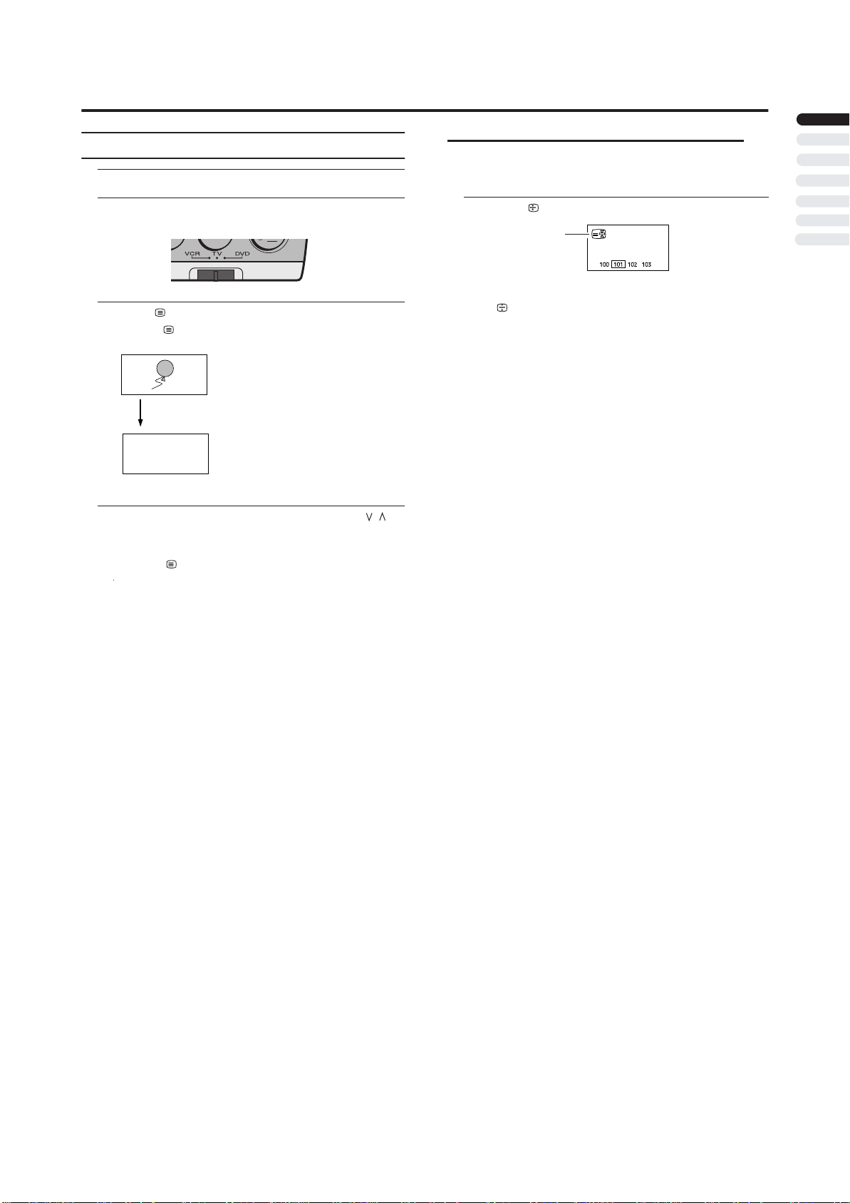
1 Make sure to set the VCR/TV/DVD switch to the
TV position.
• You cannot turn the TV on when the VCR/TV/DVD
switch is set to the VCR or DVD position.
2 Press the button on the remote control
After a short interval the power lamp changes from red
to green.
• Check that the AC plug on the power cord from the
TV is connected to AC outlet.
Power lamp
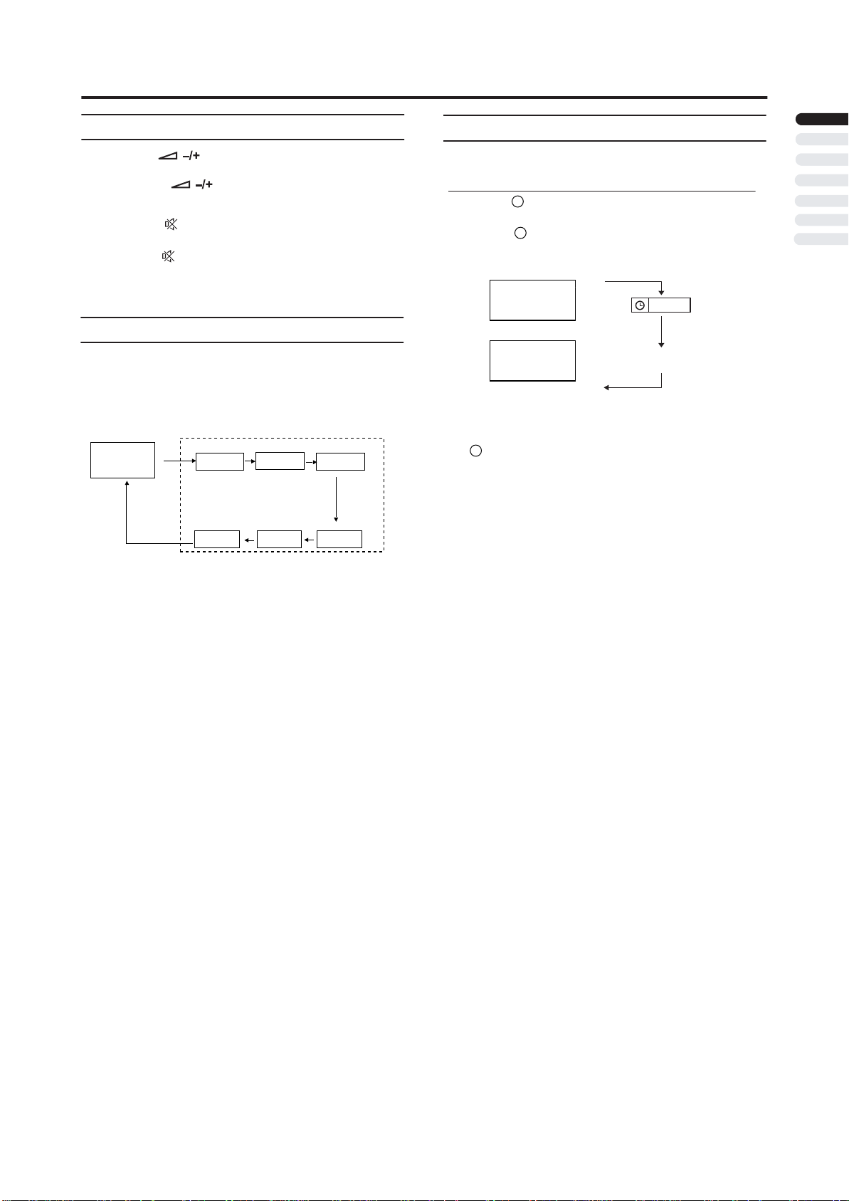
3 AUTO PROGRAM menu appears.
AUTO PROGRAM
LANGUAGE ENGLISH
COUNTRY UK
A .P .S
4
P
ress
t
:
SELECT
/
he buttons to choose the
:MOVE
LANGUAGE.
5
P
ress
/
t
he buttons to choose the ENGLISH.
The on-screen display will then be in English.
6
P
ress
country where you are.
7
P
ress
A.P.S.
8
Press the OK button to start A.P.S.
/
he and buttons to choose the
t
/
t
he buttons to choose the
Then press buttons.
A.P.S.
START
OK : START
A.P.S.
A.P.S. IS RUNNING
MENU : EXIT
/
/
The AUTO PROGRAM menu appears and received TV
channels are automatically stored in the programme
numbers.
• To cancel the AUTO PROGRAM function:
Press the MENU button.
After the TV channels have been registered in
the programme numbers, the PROGRAM
menu appears
• If you want to, you can now edit the programme
numbers using the PROGRAM function.
For details, see “To edit the PROGRAM menu” on
page 23.
ENGLISH
.
Remote control
Remote control
sensor
sensor
7
Page 34

Initial settings
Now, the initial settings are complete, and you can
watch the TV
•
If your TV can detect the TV channel name from the TV
channel broadcast signal, the TV channel name is
assigned to the programme number to which the
TV channel has been set. However, which TV channels
are set to which programme numbers will depend
on the area in which you live.
• If a TV channel you want to view is not set to a
programme number, you can set it using the
MANUAL function. For details, see “To edit the
PROGRAM menu" on page 23.
• The AUTO PROGRAM function does not set the
programme number PR 0 (AV) for your video cassette
recorder. You will need to set this using the MANUAL
function.
• In some areas you may get TV reception from more than
one transmitter, for example different ITV regions. In
this case each TV channel could be set twice. If this
happens, the first set of channels will have the stronger
signal. If you want to delete the second set of channels,
you will have to do it manually (see page 22).
8
Page 35

TV buttons and functions
1
Press the button or P buttons to turn the TV
on from standby mode
• Check that the AC plug on the power cord from the TV
is connected to correctly AC outlet.
/
Choose a TV channel
Turn the TV on from standby mode
Press the P buttons to choose a programme
/
number or an EXT terminal
ENGLISH
Watch images from external devices
2
Press the TV/AV button to choose a TV/AV
terminal
-1
EXT modes
EXT-2
EXT-3 S
EXT-2 S
EXT-3
TV mode
Last
program
number
EXT
PC
Adjust the volume
1
Power lamp
2 Remote control sensor
3
MENU button
4
TV/AV OK button
5
(Volume) button
/
6
P buttons
Standby botton
7
Headphone jack (mini jack)
8
Press the buttons
3
4
5
The volume level indicator appears.
Using the Menu
Use the MENU button.
Refer to “Using the TV’s menu” (see page 17) for details of
using the menu.
6
7
8
9
Page 36

Remote control buttons and functions
1 Muting button
2 Number buttons
3 Information button
4 ZOOM button
5
button
6
button
7 // buttons
8 (Text) button
9 P buttons
10 VCR/DVD/Teletext control buttons
/
11 buttons
button
12
button
13
14
Standby button
VCR/TV/DVD switch
15
button
16
AV
button
17
18
Picture button
Color buttons
19
20
MENU button
21
OK
button
22
/
buttons
BACK
23
24
25
button
26
button
button
buttons
Turn the TV on or off from standby
mode
1 Make sure to set the VCR/TV/DVD switch to the
TV position.
• You cannot turn the TV on or off when the VCR/TV/
DVD switch is set to the VCR or DVD position.
2 Press the (standby) button to turn the TV on
or off.
When the TV is turned on, the power lamp changes from
red to green.
• The power can be turned on by pressing
buttons or Number buttons.
P
• Check that the AC plug on the power cord from the
TV is connected to AC outlet.
/
Choose a TV channel
Use the number buttons:
Enter the programme number of the
channel using the number buttons.
Example:
•PR press 66
• PR 12 press 1 and 2
Use the
Press th buttons to choose the
programme number want
• If you do not have a clear picture or no colour appears,
change the colour system manually. Follow the description
"MUNUAL" on page 22 to try to change COLOUR
SYSTEM.
• If the SOUND SYSTEM setting for a TV channel is
incorrect, it may provent the sound from being issued.
Follow the description "MANUAL" on page 22 to try
to change the SOUND SYSTEM setting.
P
e
/
/
P
buttons:
you
.
10
Page 37
Remote control buttons and functions
Adjust the volume
Press the buttons to adjust the volume.
The volume indicator appears and the volume changes as
you press the buttons.
Muting the sound
Press the (muting) button to turn off the
sound.
Pressing the (muting) button again restores the previous
volume level.
Watch images from external equipment
Use the AV button:
Press the
terminal.
TV mode
Last
Programme
number
To use the Programme number 0:
When the TV and VCR are connected only by the Aerial
cable, choosing the Programme number 0 allows you to
view images from the VCR. Set the VCR RF channel to
the Programme number 0 manually. For details, see
"MANUAL" on page 21.
button to choose an EXT
AV
EXT modes
-1
EXT
PC
EXT-2
EXT-3 S
EXT-2 S
EXT-3
Displaying the source information
You can display the source information and current time on
the screen.
i
i
i
(information) button changes the display as
01 BBC
STEREO
TV
EXT-1
EXT-1
EXT-1
Signal source
12 : 00
No display
Press the (information) button to display the
source information.
Pressing the
follows:
or
• The source information and current time switched by
(information) button.
• The source type :
TV/EXT-1/EXT-2/EXT-2 S/EXT-3/EXT-3 S/PC
• If the programme being watched does not have Teletext
transmission, only a box will be displayed at the same
location.
• When watching videos, an incorrect current time
is sometime displayed.
• In PC mode, the current time will not be displayed
ENGLISH
In the PC mode:
If following message appears, the power lamp blinks in
amber and the TV goes in to reduced power mode.
- "No SIGNAL"
- "CABLE NO INSERT"
- "OUT OF RANGE"
See "Troubleshooting" on page 30 for detials of this messages.
11
Page 38

Remote control buttons and functions
ZOOM function
You can change the screen size according to the picture
aspect ratio. Choose the optimum one from the following
ZOOM modes.
AUTO:
When a WSS (Wide Screen Signalling) signal, which shows
the aspect ratio of the picture, is included in the broadcast
signal or the signal from an external device, the TV
automatically changes the ZOOM mode to 16:9 ZOOM
mode or FULL mode according to the WSS signal.
If a WSS signal is not included, the picture is displayed in
accordance with the ZOOM mode set with the 4:3 AUTO
ASPECT function.
• When the AUTO (WSS) mode does not function
correctly due to poor WSS signal quality or when you
want to change the ZOOM mode, press the ZOOM
button and change to another ZOOM mode.
REGULAR:
Use to view a normal picture (4:3 aspect ratio) as this is its
original shape.
PANORAMIC:
This stretches the left and right sides of a normal picture
(4:3 aspect ratio) to fill the screen, without making the
picture appear unnatural.
Choose the ZOOM mode
1Press the button to display the ZOOM
menu
• The button does not work in the twin
pictures mode.
ZOOM
ZOOM
Adjusting the visible area of the picture
If subtitles or the top (or bottom) of the picture are cut off,
you can adjust the visible area of the picture manually.
1Press the button
The ZOOM menu appears.
2Press the OK button to display the ZOOM mode
indicator
The indicator appears.
3 While it is displayed, press the buttons to
change the position of the picture
• You cannot adjust the visible area in REGULAR or
FULL mode.
16:9
ZOOM
ZOOM
/
• The top and bottom of the picture are slightly cut off.
14:9 ZOOM:
This zooms up the wide picture (14:9 aspect ratio) to the
upper and lower limits of the screen.
16:9 ZOOM:
This zooms up the wide picture (16:9 aspect ratio) to the
full screen.
16:9 ZOOM SUBTITLE:
This zooms up the wide picture (16:9 aspect ratio) with
subtitles to the full screen.
FULL:
This uniformly stretches the left and right sides of a normal
picture (4:3 aspect ratio) to fill the wide TV screen.
• For 16:9 aspect ratio pictures that have been squeezed
into a normal picture (4:3 aspect ratio), use the FULL
mode to restore the picture to its original shape.
12
Page 39

Remote control buttons and functions
Sleep timer function
The Sleep Timer can turn the TV off for you after you fall
asleep. Program it to work in intervals of 10 minutes, for
a total time of up to 120 minutes.
Press the button.
Picture mode
You can choose one of four PICTURE MODEs to adjust
the picture settings automatically.
Press the PICTURE button.
BRIGHT:
Heightens contrast and sharpness.
STANDARD:
Standardizes picture adjustment.
SOFT:
Softens contrast and sharpness.
MANUAL:
User define.
Using the PCPIP function
A PC picture and TV or a video program from an
external device can be watched at the same time.
1Press
2Press the button to change the position of
sub-picture
h
e button.
t
Main-
picture
Main-
picture
D005 7
Picture in picture mode
Cancel the PIP function
Subpicture
ENGLISH
Change sub-picture position
3Press the button to change the sub-picture
size
Picture in picture mode
Main-
picture
Main-
picture
Change sub-picture size
Subpicture
Subpicture
13
Page 40

Remote control buttons and functions
• If the main-picture signal is poor, the quality of the
sub-picture may also be poor.
• If the pictures have different standards, the top and
bottom of one of them may be missing.
• If you press the menu button when the PIP functions
is on, PC menu will appear. To display the TV menu,
change the mode to the TV mode.
Operating a JVC brand VCR or DVD
player
These buttons will operate a JVC brand VCR or DVD
player. Pressing a button that looks the same as the device’s
original remote control button has the same effect as the
original remote control.
1 Set the VCR/TV/DVD switch to the VCR or DVD
position
VCR:
When you are using a VCR, set the switch to the VCR
position. You can turn the VCR on or off with the
(Standby) button.
DVD:
When you are using a DVD player, set the switch to the
DVD position. You can turn the DVD player on or off
with the (Standby) button.
2 Press the VCR/DVD Control Button to control
your VCR or DVD player
• If your device is not made by JVC, these buttons will
not work.
• Even if your device is made by JVC, some of these
buttons may not work, depending on the device you
are using.
• You can use the p buttons to choose a TV channel
the VCR will receive, or choose the chapter the DVD
player plays back.
• Some models of DVD player use the p buttons for
both operating the fast forward/backward functions
and for choosing the chapter.
/
/
• Set the VCR/TV/DVD switch to the TV position
when you turn the TV on or off.
14
Page 41
Teletext function
Basic operation
1 Choose a TV channel with a teletext broadcast
Hold
You can hold a teletext page on the screen for as long as
you want, even while several other teletext pages are being
received.
2 Make sure to set the VCR/TV/DVD switch to the
TV position.
3 Press (Text) button to display the teletext
Pressing (Text) button changes the mode as follows:
TV mode
TEXT--TEXT--TEXT---
Text mode
D104 3
4 Choose a teletext page by pressing the P
/
buttons, number buttons or colour buttons
To return to the TV mode:
Press the (Text) button.
• If you have trouble receiving teletext broadcasts,
consult your local dealer or the teletext station.
• The ZOOM function will not work in the TV and text
mode or Text mode.
• You cannot operate menus when viewing a teletext
programme.
• Language display depends on the country which was
set on the COUNTRY menu. If characters on a
Teletext programme do not appear properly, change
the COUNTRY Setting to other country’s.
.
Press the (Hold) button
Hold indication
ENGLISH
To cancel the Hold function:
Press (Hold) button again.
15
Page 42

Teletext function
Sub-page
Some teletext pages include sub-pages that are
automatically displayed.
1 Choose a teletext page that includes sub-pages
Press the button, Sub-page numbers can be viewed
and displayed at the screen.
2 Press the number buttons to choose a sub-page
number
Sxxxx : xxxx is the number 0 ~ 9 that you entered.
For example, sub-page 1 is S0001, you must enter 0,0,
0 and 1 serially to view sub-page S0001.
Reveal
Some teletext pages include hidden text (such as the
answers to a quiz).
You can display the hidden text.
Each time you press the (Reveal) button, text is
hidden or revealed
Size
You can double the height of the teletext display.
Cancel
You can search for a teletext page while watching TV.
1 Press the number button to enter a page
number, or press a colour button
The TV searches for a teletext page.
2 Press the (Cancel) button
The TV programme appears. When the TV finds the
teletext page, its page number appears in the upper left
of the screen.
3 Press the (Cancel) button to return to a
teletext page when the page number is on the
screen
• The TV mode cannot be resumed by pressing the
(Cancel) button. To return to the TV mode press
button.
Press the (Size) button.
Index
You can return to the index page instantly.
Press the (Index) button
Returns to page 100 or a previously specified page.
16
Page 43

Using the TV’s menu
This TV has a number of functions you can operate using
menus. To use all your TV’s functions, you need to
understand the basic menu operating techniques fully.
BACK
PC
3Press the buttons to choose a function
/
• For details of the functions in the menus, see the
following pages.
4Press the buttons to choose the setting of
/
that function
• If you want to operate a function which appears only
with its name, follow the descriptions of that function
on the following pages.
• The display appearing at the bottom of a menu shows
you a button on the remote control that you can use
when you operate a chosen function.
5Press the
MENU
button to complete the setting
The menu disappears.
• When watching the television with the NTSC system,
the menus are displayed at about half of their normal
vertical size.
• The menu will be disappear if you press the P
/
buttons, the AV button or the number buttons while
the menu is
displayed.
Operation with the buttons on the TV
You can also operate the menus using the buttons on the
front panel of the TV.
ENGLISH
Basic operation
1 Press the MENU button to display the MENU (main
menu)
MENU
PICTURE
SOUND
FEATURES
INSTALL
: SELECT :MOVE
2 Press the and buttons to choose a
/
menu title, and press the OK button
The menu appears.
To return to the previous menu:
Press the BACK button on the remote control or the
MENU button on the TV.
To exit
a menu instantly:
Press the MENU button on the remote control or
press the MENU button on the TV several times.
/
MENU button
OK button
buttons
/
buttons
/
The menu will disappear after about one minute if no
operation is performed.
17
Page 44
PICTURE SETTING
Refer to “Using the TV’s menu” (see page 17) for details of
displaying the menu.
PICTURE
PICTURE MODE MANUAL
CONTRAST
BRIGHT-1
SHARP
COLOUR
HUE
BRIGHT-2
COLOUR TEMP NORMAL
RESET
: SELECT
:MOVE
PICTURE MODE
You can choose one of four PICTURE MODEs to adjust
the picture settings automatically.
BRIGHT:
Heightens contrast and sharpness.
STANDARD:
Standardizes picture adjustment.
SOFT:
Softens contrast and sharpness.
MANUAL:
User define.
Picture Adjustment
You can change the picture settings of each PICTURE
MODE mode as you like.
COLOUR TEMP.
You can select one of three COLOUR TEMP. modes (three
tones of white) to adjust the white balance of the picture.
Since white is the colour which is used as a reference for all
the other colours, changing the COLOUR TEMP. mode
affects the appearance of all the other colours on the screen.
COOL:
A bluish white. Using this mode when watching bright
pictures allows you to enjoy a more vivid and bright picture.
NORMAL:
The normal white colour.
WARM:
A reddish white. Using this mode when watching films
allows you to enjoy colours that are characteristic of films.
RESET
You can reset the picture settings you have chosen to the
default settings.
CONTRAST:
You can adjust the picture contrast.
:lower
: higher
BRIGHT-1:
You can adjust the picture brightness.
:darker
: brighter
SHARP:
You can adjust the picture sharpness.
:softer
:sharper
COLOUR:
You can adjust the picture colour.
: lighter
: deeper
HUE:
You can adjust the picture tint.
:reddish
:greenish
BRIGHT-2:
You can adjust the back light.
:darker
:lighter
You can change the HUE setting(picture hue) when the
colour system is NTSC3.58 or NTSC4.43.
18
Page 45

SOUND SETTING
Refer to “Using the TV’s menu” (see page 17) for details of
displaying the menu.
SOUND
BASS
TREBLE
BALANCE
HYPER SOUND OFF
: SELECT
:MOVE
Sound Adjustment
You can adjust the sound to your liking.
BASS:
You can adjust the low tone of the sound.
: weaker
: strong
TREBLE:
You can adjust the high tone of the sound.
: weaker
: strong
BALANCE:
You can adjust the volume balance between the left and
right speaker.
:turn the left speaker’s volume level up.
: turn the right speaker’s volume level up.
HYPER SOUND
You can enjoy Surround sound with a “live” effect by using
the function.
HYPER SOUND
ON:
HYPER SOUND
OFF:
function is turned on.
function HYPER SOUND
is turned off.
ENGLISH
19
Page 46

FEATURES
Refer to “Using the TV’s menu” (see page 17) for details of
displaying the menu.
FEATURES
BLUE BACK OFF
CHILD LOCK OFF
EXT-2 OUTPUT TV
: SELECT
BLUE BACK
You can set the TV to automatically change to a blue screen
and mute the sound if the signal is weak or absent, or when
there is no input from an external device.
ON:
This function is turned on.
OFF:
This function is turned off.
CHILD LOCK
When the CHILD LOCK mode is on, the TV buttons will be
locked except Power ON/OFF. TV only can be controled by
remote controller.
:MOVE
EXT-2 OUTPUT
You can choose a signal source to be output from the EXT-2
terminal.
You can do this with the output signals of the devices
connected to EXT-1 termainal, or with the picture and
sound from a TV channel you are currently viewing.
Press the buttons to choose the
signal source TV/EXT-1.
• EXT-3 terminal can not be output.
/
2 0
Page 47

INSTALL
Refer to “Using the TV’s menu” (see page 17) for details of
displaying the menu.
In TV mode :
INSTALL
MANUAL
PROGRAM
: SELECT OK : MOVE
In EXT mode :
INSTALL
COLOUR SYSTEM
:
SELECT
AUTO
:MOVE
MANUAL
You can store the TV channel for which you needed.
Store them in the TV’s program numbers list
by setting the following.
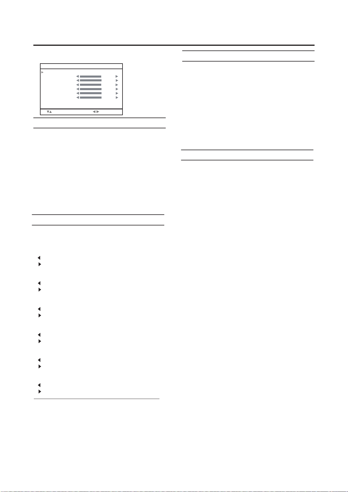
MANUAL
PROGRAM 01
BAND CH
CHANNEL 02
COLOUR SYSTEM AUTO
SOUND SYSTEM AUTO
SEARCH
FINE TUNING
STORE
: SELECT : MOVE
PROGRAM
AUTO PROGRAM
You can automatically store the TV channels for which you
have the best reception. Store them in the TV’s program
numbers list by doing the following.
Choose PROGRAM. Then press the OK button.
1
PROGRAM
01 ---02 ---03 ---04 ---05 ---06 ---07 ---08 ---09 ---10 ----
N
INSERT A.P.S.
11 ---12 ---13 ---14 ---15 ---16 ---17 ---18 ---19 ---20 ----
ME DELETE
A
2 Press the blue button, AUTO PROGRAM menu
appears.
AUTO PROGRAM
LANGUAGE ENGLISH
COUNTRY UK
A. P. S.
:
SELECT
21 ---22 ---23 ---24 ---25 ---26 ---27 ---28 ---29 ---30 ----
:MOVE
ENGLISH
1 Select PROGRAM and press the buttons to
/
choose the program number.
2 Select BAND and press the buttons to
/
choose the band type.
CH(AIR) / CC(CATV)
3 Select CHANNEL and press the buttons to
/
choose the channel number.
4 Select COLOUR SYSTEM and press the
/
buttons to choose the colour system.
AUTO / PAL / SECAM
• If you do not have a clear picture or no colour appears,
change the colour system.
5 Select SOUND SYSTEM and press the
/
buttons to choose the sound system.
AUTO / B/G / D/K / L / I
• If the SOUND SYSTEM setting for a TV channel is
incorrect, it may provent the sound from being issued.
6 Select SEARCH and press the buttons to
/
choose the serviceable TV channel.
7 If the channel reception is poor, select
FINE TUNING and press the buttons to
/
fine tune the program.
8 Select Store and press the buttons to
/
store the manual setting.
3
P
ress
/
he buttons to choose the
t
LANGUAGE.
4
P
ress
/
t
he buttons to choose the
ENGLISH.
The on-screen display will then be in English.
5
P
ress
country where you are.
/
he and buttons to choose the
t
/
6
P
ress
Th
en press the buttons.
/
he buttons to choose the A.P.S.
t
A.P.S.
START
OK : START
/
7
P
he OK button to start the A.P.S.
ress
t
A.P.S.
A.P.S. IS RUNNING
MENU : EXIT
The AUTO PROGRAM menu appears and received TV
channels are automatically stored in the programme
numbers.
• To cancel the AUTO PROGRAM function:
Press the MENU button.
21
Page 48

INSTALL
After the TV channels have been registered in
the programme numbers, the PROGRAM menu
appears
• If you want to, you can now edit the program
numbers using the PROGRAM function.
For details, see “To edit theP ROGRAM menu”
on page 22.
To edit the PROGRAM menu
You can edit the programme numbers.
Caution
• Using the NAME, DELETE or INSERT functions
rewrites the current programme numbers list.
Therefore, the programme nu of some of
the TV channels will change.
1 Choose PROGRAM, then press the OK button
PROGRAM
01 ---02 ---03 ---04 ---05 ---06 ---07 ---08 ---09 ---10 ----
N
AME DELETE
INSERT A.P.S.
2 Follow the operation description of a function
you want to use and operate the function
NAME:
This function registers a channel name (ID) to a TV
channel.
INSERT:
This function changes a programme number of a
TV channel.
DELETE:
This function deletes a TV channel you do not want to
list.
A.P.S:
This function received TV channels automatically
amnd stored in program numbers. For details,
see "AUTO PROGRAM" on page 22.
11 ---12 ---13 ---14 ---15 ---16 ---17 ---18 ---19 ---20 ----
mber
21 ---22 ---23 ---24 ---25 ---26 ---27 ---28 ---29 ---30 ----
NAME
1Press t
he and buttons to choose a TV
/
channel
Every time you press the buttons, the
programme number changes and the picture of the
TV channel stored in the programme number appears
on the screen.
2Press the red button to start the NAME function
PROGRAM
01 ---02 ----
03 ---04 ---05 ---06 ---07 ---08 ---09 ---10 ----
STORE
CANCEL
3Press th e buttons
/
channel name you want to give the TV channel
PROGRAM
01 ---02
BBC1
03 ---04 ---05 ---06 ---07 ---08 ---09 ---10 ----
STORE
CANCEL
4 Press the red button to store the setting
PROGRAM
01 ---02
BBC1
03 ---04 ---05 ---06 ---07 ---08 ---09 ---10 ----
NAME DELETE
INSERT A.P.S.
/
and
/
11 ---12 ---13 ---14 ---15 ---16 ---17 ---18 ---19 ---20 ----
/
and
11 ---12 ---13 ---14 ---15 ---16 ---17 ---18 ---19 ---20 ----
11 ---12 ---13 ---14 ---15 ---16 ---17 ---18 ---19 ---20 ----
/
21 ---22 ---23 ---24 ---25 ---26 ---27 ---28 ---29 ---30 ----
to edit the
21 ---22 ---23 ---24 ---25 ---26 ---27 ---28 ---29 ---30 ----
21 ---22 ---23 ---24 ---25 ---26 ---27 ---28 ---29 ---30 ----
22
To return to the INSTALL menu:
Press the BACK button.
To exit
a menu instantly:
Press the MENU button.
Page 49

INSTALL
INSERT
1Press t
he and buttons to choose a
/
program number for which you want
Every time you press the buttons, the
programme number changes and the picture of the
TV channel stored in the programme number appears
on the screen.
PROGRAM
01 ---02
BBC1
03
BBC2
04 ---05 ---06 ---07 ---08 ---09 ---10 ----
NAME
INSERT A.P.S.
2 Press the green button to start the INSERT
function
/
and
/
11 ---12 ---13 ---14 ---15 ---16 ---17 ---18 ---19 ---20 ----
DELETE
/
21 ---22 ---23 ---24 ---25 ---26 ---27 ---28 ---29 ---30 ----
4 Press the green button to insert the channel into
the new program number
PROGRAM
BBC2
BBC1
11 ---12 ---13 ---14 ---15 ---16 ---17 ---18 ---19 ---20 ----
01 ---02 ---03
04
05 ---06 ---07 ---08 ---09 ---10 ----
NAME DELETE
21 ---22 ---23 ---24 ---25 ---26 ---27 ---28 ---29 ---30 ----
INSERT A.P.S.
To return to the INSTALL menu:
Press the BACK button.
To exit
a menu instantly:
Press the MENU button.
ENGLISH
PROGRAM
01 ---02
03
04 ---05 ---06 ---07 ---08 ---09 ---10 ----
3Press t
he and buttons to choose a new
program number
PROGRAM
01 ---02
03
04 ---05 ---06 ---07 ---08 ---09 ---10 ----
BBC1
BBC2
11 ---12 ---13 ---14 ---15 ---16 ---17 ---18 ---19 ---20 ----
21 ---22 ---23 ---24 ---25 ---26 ---27 ---28 ---29 ---30 ----
INSERT CANCEL
/
BBC1
BBC2
/
11 ---12 ---13 ---14 ---15 ---16 ---17 ---18 ---19 ---20 ----
21 ---22 ---23 ---24 ---25 ---26 ---27 ---28 ---29 ---30 ----
INSERT CANCEL
2 3
Page 50

INSTALL
DELETE
1Press t
he and buttons to choose a
/
program number for which you want
Every time you press the buttons, the
programme number changes and the picture of the
TV channel stored in the programme number appears
on the screen.
PROGRAM
01 ---02
BBC1
03
BBC2
04 ---05 ---06 ---07 ---08 ---09 ---10 ----
NAME
INSERT A.P.S.
2 Press the yellow button to start DELETE
function
PROGRAM
01 ---02
BBC1
03
BBC2
04 ---05 ---06 ---07 ---08 ---09 ---10 ----
/
and
/
11 ---12 ---13 ---14 ---15 ---16 ---17 ---18 ---19 ---20 ----
DELETE
11 ---12 ---13 ---14 ---15 ---16 ---17 ---18 ---19 ---20 ----
DELETE
CANCEL
/
21 ---22 ---23 ---24 ---25 ---26 ---27 ---28 ---29 ---30 ----
21 ---22 ---23 ---24 ---25 ---26 ---27 ---28 ---29 ---30 ----
COLOUR SYSTEM in EXT mode
Press t
he buttons to choose the colour system
/
When you are in EXT mode, you can only change the
colour system in the INSTALL menu.
3 Press the yellow button to delete the selected
TV channel
The TV channel is deleted from the programme numbers
list.
PROGRAM
01 ---02
BBC1
----
03
04 ---05 ---06 ---07 ---08 ---09 ---10 ----
NAME
11 ---12 ---13 ---14 ---15 ---16 ---17 ---18 ---19 ---20 ----
DELETE
21 ---22 ---23 ---24 ---25 ---26 ---27 ---28 ---29 ---30 ----
INSERT A.P.S.
To return to the INSTALL menu:
Press the BACK button.
To exit
a menu instantly:
Press the MENU button.
24
Page 51

PC MENU (In PC mode only)
This TV also has a number of functions on PC mode,
you can operate using pc menus.
PC MENU
PC PICTURE POSITION
PC PICTURE
SOUND
: SELECT
1024 X 768
H : 48 kHz
OK : OK
V : 60 Hz
PC PICTURE POSITION
You can adjust the picture settings as following functions.
PC PICTURE POSITION
AUTO SETUP
H POSITION
V POSITION
CLOCK
PHASE
RESET
: SELECT
:MOVE
AUTO SETUP:
You can adjust picture settings automatically for optimized
picture position, clock and phase.
H POSITION:
You can adjust picture horizontal position.
:left
: right
V POSITION:
You can adjust picture vertical position.
:down
: up
CLOCK:
You can adjust CLOCK to fine tune picture.
PHASE:
You can adjust PHASE to fine tune picture.
RESET:
You can select RESET mode for default setting.
PC PICTURE
You can change the picture settings of each PICTURE
MODE mode as you like.
PC PICTURE
CONTRAST
BRIGHT-2
COLOUR TEMP. MANUAL
R
G
B
RESET
: SELECT
CONTRAST:
You can adjust the picture contrast.
:lower
: higher
BRIGHT-2:
You can adjust the back light.
:darker
:lighter
:MOVE
COLOUR TEMP.:
You can adjust the picture colour mode.
COOL:
A bluish white. Using this mode when watching bright
pictures allows you to enjoy a more vivid and bright picture.
NORMAL:
The normal white colour.
WARM:
A reddish white. Using this mode when watching films
allows you to enjoy colours that are characteristic of films.
MANUAL:
User defined.
R:
You can adjust the Red color component.
:reddish
: redder
G:
You can adjust the Green color component
:greenish
:greener
B:
You can adjust the Blue color component.
:blueish
:bluer
RESET:
You can select RESET mode for default setting.
SOUND
You can adjust the sound to your liking.
SOUND
BASS
TREBLE
BALANCE
HYPER SOUND OFF
: SELECT
BASS:
You can adjust the low tone of the sound.
: weaker
: strong
TREBLE:
You can adjust the high tone of the sound.
:weaker
: strong
BALANCE:
You can adjust the volume balance between the left and
right speaker.
:turn the left speaker’s volume level up.
: turn the right speaker’s volume level up.
HYPER SUOUND:
You
joy Surround sound with a “live” effect by using
can en
the HYPER SOUND functions.
ON:
HYPER SOUND
OFF:
HYPER SOUND
function is turned on.
function is turned off.
:MOVE
ENGLISH
25
Page 52

PC MENU
PC support mode list
Mode NO. Mode Name
1
2
3
4
5
The resolution and the freauencies which are
displayed on the screen may not exactly same as
this list.
The Auto SETUP functions will work automatically
when you change the resolution of PC mode. The
picture position, clock, and phase will be optimized.
Resolution
VGA 60 Hz
640x480
SVGA 60 Hz
800x600
SVGA 60 Hz
800x600
XGA 60 Hz
1024x768
WXGA
1280x768
H Freq. (kHz)
V Freq. (Hz)
31.469
59.941
35.16
56.25
37.879
60.317
48.363
60.004
47.73
60
266
Page 53

Additional preparation
Connecting external equipment
Connect the equipment to the TV, making the correct rear
panel and front panel connections.
Before connecting anything:
• Read the manuals that came with the equipment.
Depending on the equipment, the connection method
may be different from the diagram. Also, the equipment
settings may need to change depending on the
connection method.
• Turn off all the equipment including the TV.
• The “Specifications” on page 31 give the details of the
EXT terminals. If you are connecting equipment not
listed in the following connection diagram, see the table
to choose the best EXT terminal.
• Connecting cables are not supplied.
• To connect the PC, please see "Connecting the PC" on
page 28.
1 VCR (composite signal)
2 VCR (composite signal/S-VIDEO signal)
3 T-V LINK compatible VCR (composite signal/S-VIDEO
signal)
4 Decoder
5 DVD player (composite signal/S-VIDEO signal)
6 DVD player (composite signal/RGB signal)
7
PC
8 TV game (composite signal/RGB signal)
9 TV game (composite signal/S-VIDEO signal)
10 Headphones
11 Camcorder (composite signal/S-VIDEO signal)
12 SCART cable
13 Audio in
PC
14 Video cable
15 S-VIDEO cable
16 D-SUB in
ENGLISH
twithou terminal covers
PC AUDIO IN
L
R
SUBWOOFER
27
Page 54

Additional preparation
Equipment which can output the S-VIDEO
signal (Y/C signal) such as an S-VHS VCR
Connect the equipment to an EXT terminal (but not the
EXT-1 terminal).
You can choose between an S-VIDEO signal (Y/C signal).
Connecting headphones
Connect the headphones with a stereo mini-jack (3.5 mm
diameter) to the headphone socket at the TV.
Video or sound signal output from the EXT-2
terminal
You can change over the output of the video/sound signal
from the EXT-2 terminal. This is useful when you want to
dub the video/sound from another device onto the VCR
connected to the EXT-2 terminal.
TV output from the EXT-1 terminal
The video/sound signal of a TV channel you are viewing is
always output from the EXT-1 terminal.
• Changing over a programme number also changes
over the TV output from the EXT-1 terminal.
• The video/sound signal from an EXT terminal cannot be
output.
• Teletext programmes cannot be output.
Connecting the PC
Connect the PC with the D-SUB cable to the D-SUB in at
the TV, and connect the sound device of PC with a stereo
mini-jack to PC AUDIO IN.
You can adjust the picture by AUTO SETUP function when
the PC signal is output correctly, the AUTO SETUP function
can optimize the picture position, clock and phase. You can
have a fine vision after AUTO SETUP function executed.
Connecting Speakers/Amplifier
See the Audio equipment connection diagram, then connect
the audio equipment you desire to the TV.
You can use external front speakers to listen to the TV
sound instead of the TV speakers.
Before connecting anything:
• Read the manuals provided with the amplifier and
speakers.
• Turn the TV and amplifier off.
• To prevent magnetism from the speakers adversely
affecting the TV screen, use magnetically-shielded
speakers for the front speakers.
• Note that connecting cables are not supplied.
without terminal covers
L
R
SUBWOOFER
PC AUDIO IN
SUBWOOFER
L
R
1 Amplifier
2 External speakers (Magnetic-shielded type)
• The output from the AUDIO OUT terminal is not
interrupted by headphone connection to the TV. You
cannot cut the sound from the front speaker even if you
connect a headphone to the TV.
• Adjust the volume of the external speakers with the
amplifier.
• Connect the subwoofer which carried an amplifier.
• The subwoofer is interlocked with the TV volume.
28
Page 55

Troubleshooting
If a problem arises while you are using the TV, please read this troubleshooting guide carefully before you ask to have the TV
repaired. You may be able to fix it easily by yourself. For example, if the mains plug is disconnected from the mains outlet, or the
TV aerial has problems, you may think there is a problem with the TV itself.
Important:
• This troubleshooting guide only covers problems whose causes are not easy to decide. If you have a question when you are
operating a function, read the page(s) for that function carefully, not this troubleshooting guide.
• If you follow the advice in this troubleshooting guide without any success, unplug the mains plug and ask for your TV to be
repaired. Do not attempt to repair the TV by yourself or to remove the rear cover of the TV.
If you cannot turn on the TV
• Are the AC plug on the power cord from the TV is
connected to AC outlet?
• Make sure to set the VCR/TV/DVD switch to the TV
position. You cannot turn the TV on when the VCR/TV/
DVD switch is set to the VCR or DVD position.
If you cannot turn off the TV
• Make sure to set the VCR/TV/DVD switch to the TV
position. You cannot turn the TV off when the VCR/TV/
DVD switch is set to the VCR or DVD position.
No picture or no sound
• Have you chosen a TV channel with very poor
reception? If so, the BLUE BACK function will be
activated: the entire screen becomes blue, and the sound
is muted. If you still want to view the TV channel,
follow the description “BLUE BACK” on page 20 to
change the BLUE BACK function setting to OFF.
• If the SOUND SYSTEM setting for a tTV channel is
incorrect, it may prevent the sound from being issued.
Follow the description “INSTALL” on page 21 to use the
MANUAL function to try to change the SOUND SYSTEM
setting.
Poor picture
• If noise (snow) totally blocks out the picture, there may
be a problem with the aerial or aerial cable. Check the
following to try to solve the problem:
–Have the TV and aerial been connected properly?
–Has the aerial cable been damaged?
–Is the aerial pointing in the right direction?
–Is the aerial itself faulty?
• If the TV or aerial suffers interference from other
equipment, stripes or noise may appear in the picture.
Move any equipment such as an amplifier, personal
computer, or a hair drier, that can cause interference
away from your TV. Or try moving the TV. If the aerial
suffers interference from a radio tower or high-voltage
wire, please contact your local dealer.
• If the TV suffers interference from signals reflecting
from mountains or buildings, double-pictures (ghosting)
will occur. Try to change the aerial’s direction or replace
it with one with better directionality.
• Have the COLOUR and BRIGHT settings been adjusted
properly? Follow the description “Picture Adjustment”
on page 18 to try to adjust them properly.
• Videotaping teletext is not recommended because it may
not record correctly.
• When viewing images from commercially available
video software products, or videos from videotapes
which have been recorded improperly, the top of the
image may be distorted. This is due to the condition of
the video signal. There is nothing wrong with the TV.
Poor sound
• Have you adjusted BASS or TREBLE properly? If not,
follow the description “Sound Adjustment” on page 19.
If the TV does not respond to the remote
control
• Have the batteries of the remote control worn out?
Follow the description “Putting the batteries into the
Remote control” on page 5 and replace them with new
batteries.
• Have you attempted to use the remote control from the
sides or rear of the TV or from more than seven metres
away from the TV? Use the remote control in the front of
your TV or from less than seven metres away.
• When you are viewing a teletext programme, you cannot
operate the menus. Press the button to return to the
ordinary TV programme, and then try operating the
menus.
• If the TV suddenly stops responding, disconnect the
power cord of the TV from the AC outlet.
Connect them to the AC outlet again to turn on the TV.
If the TV returns to a normal state, it is not a failure.
ENGLISH
29
Page 56

Other concerns
• When the SLEEP TIMER function operates, the TV is
automatically turned off. If the TV suddenly turns off,
try to press the (standby) button to turn on the TV
once again. If the TV goes back to normal, there is no
problem.
• When the TV is receiving a wide-screen signal (WSS) or
a signal from an external device affecting the screen
size, the ZOOM mode automatically changes. When you
want to resume the previous ZOOM mode, press the
button again.
ZOOM
• It takes a short period of time from the time an operation
such as changing channels is performed until an image is
displayed. This is not a malfunction. This is the time
required for the image to stabilize before it can be
displayed.
• The TV may make a crackling sound due to a sudden
change in temperature. The picture or sound may be
normal. If you hear crackling sounds frequently while
you are viewing the TV, there may be other causes. As a
precaution, ask your service technician to inspect it.
• In the twin pictures mode the sub-picture may disappear
when the external device is operated. If this happens,
press the button and display the sub-picture again.
• The headphone volume is adjusted with the
“HEADPHONE” menu. It cannot be adjusted with the
(volume) buttons.
• The top of the TV and the screen may become hot during
use but this has no affect on the performance of the TV.
Ensure that the ventilation holes are not blocked.
• When the picture is unstable, the screen may become
white for a moment. This occurs when the signal which
drives the liquid crystal is missing. This is not a
malfunction.
• When a still image has been displayed for a long period,
a faint residual image may remain on the screen for a
short time after the power has been turned off or when
another image is displayed. This is not a malfunction and
the image will eventually disappear.
• When the correct picture has not been displayed on screen,
the following error messages will display on screen.
NO SIGNAL - TV recived no signal from PC, you may
check your PC is working correctly or not.
CABLE NO INPUT - The cable is not connected correctly.
Ensure that the cable is connected correctly.
OUT OF RANGE - The picture resolution is out of limit.
Ensure that the PC picture resolution is set correctly.
Troubleshooting
30
Page 57

Specifications
Item
Broadcasting systems CCIR B/G, I, D/K, L
Colour systems PAL, SECAM
Channels and frequencies • E2-E12, E21-E69, S1-S41, X, Y, Z, Z+1, Z+2, ITALY A-H, ITALY H+1, ITALY H+2, F2-F10, F21-F69, R1-R12,
Sound-multiplex systems A2 (B/G, D/K), NICAM (B/G, I, D/K, L) system
Teletext systems FLOF (Fastext), TOP, WST (World Standard System)
Power requirements TV : 12V DC, AC adapter : 100 - 240 V AC, 50/60 Hz
Power consumption 60 W, Standby: 6 W
Screen size Viewable area 43.5 cm (measured diagonally)
Display resolution 1280 x 768 (W-XGA)
Audio output Rated Power output: 3 W + 3 W
Speakers 5.4 cm round x 2
EXT-1 terminal Euroconnector (21-pin, SCART)
EXT-2 terminal Euroconnector (21-pin, SCART)
EXT-3 terminal
AUDIO OUT terminal
PC INPUT terminal Analog RGB:D-SUB (15 pins) x 1, PC AUDIO IN x 1
Headphone jack Stereo mini-jack (3.5 mm in diameter)
Model
• The EXT terminals also support the NTSC 3.58/4.43 MHz system.
• French cable TV channel of broadcast frequencies 116 - 172 MHz and 220 - 469 MHz
• Video input, Audio L/R inputs and RGB inputs are available.
• TV broadcast outputs (Video and Audio L/R) are available.
• Video input, S-VIDEO (Y/C) input, Audio L/R inputs and RGB inputs are available.
• Video and Audio L/R outputs are available.
RCA connectors x 3, S-VIDEO connector x 1
• Video input, S-VIDEO(Y/C) and Audio L/R inputs are available.
RCA connectors x 3
• Audio L/R outputs and a subwoofer output are available.
• PC signal and audio inputs are available.
LT-17E31BUG/LT-17E31SUG
R21-R69, IR A-J
ENGLISH
Dimensions (W H D) 465 mm x 325 mm x 78 mm(TV only)
Weight 6.1kg(TV only)
Accessories Remote control unit x 1
465 mm x 363 mm x 190 mm
7.3kg
AA/R6 dry cell battery x 2
AC adapter x 1 (HP-OL060D03)
Power cord x 1
(RM-1860)
Design and specifications subject to change without notice.
Pictures displayed on the screen using this TV’s ZOOM functions should not be shown for any commercial or demonstration purpose
in public places (cafes, hotels, etc.) without the consent of the owners of copyright of the original picture sources, as this constitutes an
infringement of copyright.
31
Page 58

5
© 2003 VICTOR COMPANY OF JAPAN, LIMITED
5030057015
1003-MK-TU
Page 59
LT-17E75 BJG
LT-17E75 SJG
LCD FLAT TELEVISION INSTRUCTIONS
1
Page 60

Warning
DO NOT cut off the mains plug from this equipment. If
the plug fitted is not suitable for the power points in your
home or the cable is too short to reach a power point, then
obtain an appropriate safety approved extension lead or
adaptor or consult your dealer.
If nonetheless the mains plug is cut off, remove the fuse and
dispose of the plug immediately, to avoid a possible shock
hazard by inadvertent connection to the mains supply.
If a new mains plug has to be fitted, then follow the
instruction given below:
Important
Do not make any connection to the larger terminal which is
marked with the letter E or by the safety earth symbol or
coloured green or green-and-yellow.
The wires in the mains lead on this product are coloured in
accordance with the following code:
Blue: Neutral
Brown: Live
As these colours may not correspond with the coloured
marking identifying the terminals in your plug proceed as
follows:
The wire which is coloured blue must be connected to the
terminal which is marked with the letter N or coloured
black.
The wire which is coloured brown must be connected to the
terminal which is marked with the letter L or coloured red.
When replacing the fuse, use only a correctly rated
approved type and always re-fit the fuse cover.
If in doubt — consult a competent electrician.
How to replace the fuse
Open the fuse compartment with a
blade screwdriver, and replace the
fuse.
F use
Guidelines for safe operation
This equipment has been designed and manufactured to comply with international safety standards. However, as with any electrical
appliance, care must be taken to ensure optimal results and operational safety.
• Before attempting to use this equipment, read the operating instructions thoroughly.
• Ensure that all electrical connections (including the mains plug, extension leads, etc.) have been made in accordance with the
manufacturer’s instructions.
• If ever in doubt about the installation, operation or safety of this equipment, consult your dealer.
• Handle all glass panels or covers with care.
• Never operate this equipment if it appears damaged or operates abnormally. Turn the power off, disconnect the main power plug
and consult your dealer.
• Never remove any affixed panels or covers. Doing so may result in electrical shock.
• Never leave this equipment operating unattended unless otherwise specifically stated that it is designed to do so or in standby
mode. Only use the designated power switch to turn off the power and ensure that all potential users are instructed how to do so.
Make special arrangements for infirm or handicapped persons.
• Never watch TV while operating a motor vehicle. It is illegal to watch TV while driving.
• Never listen to headphones at high volume. Doing so may damage your hearing.
• Never obstruct the ventilation of this equipment. Doing so may cause overheating and result in a malfunction or damage.
• Never use makeshift stands or attempt to affix legs with wood screws. When using a manufacturer’s approved stand or legs, use
only the fixtures provided and follow the installation instructions.
• Never allow this equipment to be exposed to rain or moisture.
• Never allow anyone, especially children, to insert anything into an opening in the case. Doing so may result in a fatal electrical
shock.
• Never guess or take chances with electrical equipment of any kind. It is better to be safe than sorry.
Page 61

Thank you for buying this JVC LCD flat television.
To make sure you understand how to use your new TV, please read this manual thoroughly before you begin.
(“LCD” stands for Liquid Crystal Display.)
WARNING: TO PREVENT FIRE OR SHOCK HAZARD, DO NOT EXPOSE THIS APPLIANCE TO RAIN OR
MOISTURE.
WARNING
Always use the provided AC adapter and power cord.
WARNING
• Fingers may be trapped under the TV causing injuries. Hold the TV at the
bottom in the middle, and do not allow it to tilt up or down.
• The TV may fall causing injuries. Hold the bottom of the stand with your
hand and tilt the TV up and down.
• Do not allow children to hang from the TV, place their elbows on the TV
or lean against the TV. Doing so may cause the TV to fall over and lesd
to injuires.
CAUTION:
• To avoid electric shock or damage to the unit, first firmly
insert the small end of the power cord into the AC Adpater
unit it is no longer wobbly, and then plug the larger end of
power cord into an AC outlet.
CAUTION:
• Operate only from the power source specified – 240 V,
50/60 Hz) on the AC adapter.
• Avoid damaging the AC plug, AC adapter and power cord.
•
(AC 100 • only
• When you are not using this unit for a long period of time, it is
recommended that you disconnect the power cord from the
main outlet.
CAUTION ON HEATING OF AC ADAPTER:
In using, the AC adapter get heat on the sunface of case.
•
It is normal, not defective. while it is in operation.
• Don't be covered with any material on case of AC adapter
NOTES:
• The rating plate (serial number plate) and safety caution
are on the back of the main unit.
• The rating information and safty causion of the AC Adapter
are on its upper and lower sides.
1
Page 62

Point defects
LCDs use collections of fine pixels to display images. While there is no problem with more than 99.99% of these pixels, please
understand that a very small number of pixels may not light or may light all the time.
Distance recommendations
Avoid improper installation and never position the unit where good
ventilation is impossible.
When installing this TV, distance recommendations must be maintained
between the set and the wall, as well as inside a tightly enclosed area or
piece of furniture.
150 mm 150 mm
200 mm 2 00 mm
50 mm
Keep to the minimum distance guidelines shown for safe operation.
Failure to take the following precautions may cause damage to the television or remote control.
DO NOT block the TV’s ventilat ion opening s or holes.
(If the ventilation openings or holes are blocked by a newspaper or cloth, etc., the heat may not be able to get out.)
DO NOT place anything on top of the TV.
(such as cosmetics or medicines, flower vases, potted plants, cups, etc.)
DO NOT allow objects or liquid into the cabinet openings.
(If water or liquid is allowed to enter this equipment, fire or electric shock may be caused.)
DO NOT place any naked flame sources, such as lighted candles, on the TV.
DO NOT subject the TV to direct sunlight.
The surface of the TV screen is easily damaged. Be very careful with it when handling the TV.
Should the TV screen become soiled, wipe it with a soft dry cloth. Never rub it forcefully.
Never use any cleaner or detergent on it.
If there is a fault, unplug the unit and call a service technician. Do not attempt to repair it yourself or remove the rear cover and the
AC adapter.
Cleaning the screen
The screen is coated with a special thin film to reduce reflection. If this film is
and other problems that can not be repaired may occur. Pay attention to the following when handling the screen.
• Do not use glue or adhesive tape on the screen.
• Do not write on the screen.
• Do not allow the screen to come in contact with any hard objects.
• Do not allow condensation to form on the screen.
• Do not use alcohol, thinner, benzene or other solvents on the screen.
• Do not rub the screen hard.
da
maged, uneven colors, discoloration, scratches,
2
Page 63

CONTENTS
Setting up your TV..................................4
Installation..........................................................4
Using the stand ..................................................4
Putting the batteries into the Remote control.....5
Remove the terminal cover ................................5
Connecting the aerial and video cassette
recorder (VCR)...................................................6
Connecting the power cord to the AC outlet ......6
Initial settings .........................................7
TV buttons and functions ......................9
Turn the TV on from standby mode ...................9
Choose a TV channel ........................................9
Watch images from external devices .................9
Adjust the volume ..............................................9
Using the Menu..................................................9
Remote control buttons and
functions............................................10
Turn the TV on or off from standby mode........10
Choose a TV channel ......................................10
Adjust the volume ............................................11
Watch images from external equipment ..........11
Displaying the source information .....................11
ZOOM function.................................................12
Sleep timer funtion...........................................13.
Picture mode....................................................13.
Using the PCPIP
Operating a JVC brand VCR or DVD player....14
function
...............................13
Sound setting........................................19
Sound Adjustment........................................... 199
HYPER SOUND
.............................................. 199
FEATURES............................................20
BLUE BACK.................................................... 201
CHILD LOCK................................................... 201
EXT-2 OUTPUT............................................... 200
INSTALL................................................21
MANUAL.......................................................... 213
PROGRAM..................................................... 213
To edit the PROGRAM menu.......................... 224
PC MENU...............................................25
PC PICTURE POSITION................................. 253
PC PICTURE................................................... 253
SOUND............................................................ 254
PC support mode list........................................ 264
Additional preparation.........................27
Connecting external equipment ...................... 278
Troubleshooting...................................29
Specifications.......................................31
Teletext function...................................15
Basic operation ................................................15
Hold..................................................................15
Sub-page .........................................................16
Reveal..............................................................16
Size ..................................................................16
Index ................................................................16
Cancel..............................................................16
Using the TV’s menu............................17
Basic operation ................................................17
Picture setting.......................................18
PICTURE MODE .............................................18
Picture Adjustment...........................................18
COLOUR TEMP...............................................18
RESET..............................................................18
3
Page 64

Setting up your TV
Installation
Cautions for installation
• Install the TV in a corner on a wall or on the floor so as to keep cords out of the way.
• The TV will generate a slight amount of heat during operation. Ensure that sufficient space is available around the TV to allow
satisfactory cooling. See “Distance recommendations” on page 2.
Using the stand
This TV comes with a Table Top Stand already
attached.
This stand can be used to adjust the direction of the TV
screen 5° up, 10° down, and 20° to the left or right.
Tilt the TV up and down:
While holding the bottom of the stand with one hand, use
your other hand to hold the middle of the top of the TV and
slowly tilt the TV up and down.
• As a safety measure, the stand is constructed so that it
requires a certain amount of force to tilt the TV.
Rotate the TV to the left and right:
While holding the bottom of the stand with one hand, use
your other hand to hold the edge of the panel and slowly
adjust the direction of the TV screen.
Cable holder
A cable holder which is used to keep the connection cables
tidy is attached to the back of the stand.
cable holder
4
Page 65

Setting up your TV
Putting the batteries into the Remote control
Use two AA/R6 dry cell batteries.
Insert the batteries from the - end, making sure the + and - polarities are correct.
• Follow the warnings printed on the batteries.
• Battery life is about six months to one year, depending on your frequency of use.
• The batteries we supply are only for setting up and testing your TV, please replace them as soon as you need to.
• If the remote control does not work properly, replace the batteries.
Remove the terminal cover
There are connection terminals behind the covers of the rear of the TV. Remove the cover before
connecting a DVD or VCR.
The covers can be removed by removing the hook at the top and then pulling out while lifting slightly. To replace the covers,
first connect the hook at the bottom of the cover to the TV and then insert the hook at the top.
• Leave the covers off if they do not fit properly. Do not force to replace the covers. Doing so may cause damages of the
connection cables and the covers.
• Leave these covers off when mounting the TV on a wall.
• 100mm mount based on VESA regulation is equipped.
• The handle and the stand can be left by loosing the screws with a screwdriver when mounting the TV on a wall.
• Spread a soft cloth on a flat table and then place the TV on the cloth with the screen facing downwards when you leave the
handle and the stand.
5
Page 66

Setting up your TV
Connecting the aerial and video
cassette recorder (VCR)
• The connectin
• For further details, refer to the manuals provided with
the devices to be connected.
If you are connecting a VCR, follow
in the diagram below.
If you are not connecting a VCR, follow .
• You can watch a video using the VCR without doing .
For details, see your VCR instruction manual.
• To connect the PC, please see "Connecting the PC"
on page
• To connect more equipment, please see “Connecting
external equipment” on page 27.
• To connect additional audio equipment, see “Connecting
Speakers/Amplifier” on page 28.
g cables are not pro
28.
without terminal covers
vided.
Connecting the power cord to the AC
outlet
If you are connecting a AC adapter,
in the diagram below.
• Connect to the TV and to the AC outlet.
Caution
• Operate only from the power source spec
– 240 V, 50/60 Hz) on the unit.
• Remove the AC plug from the outlet to completely
disconnect the TV from the power supply.
follow
ified (AC 100
75-
ohm
Coaxial
Cable
Aerial
VCR
75-ohm
Coaxial
Cable
To Aerial
Output
n
21-pi
SCART
Cable
6
Page 67

Initial settings
When the TV is first turned on, it enters the initial setting
mode. Follow the
make the initial
instructions on the on-screen display to
settings.
VCR/TV/DVD
Switch
Yellow button
Blue butOKton
BACK
___ ___
PC
1 Make sure to set the VCR/TV/DVD switch to the
TV position.
• You cannot turn the TV on when the VCR/TV/DVD
switch is set to the VCR or DVD position.
2 Press the button on the remote control
After a short interval the power lamp changes from red
to green.
• Check that the AC plug on the power cord from the
TV is connected to AC outlet.
Power lamp
3 AUTO PROGRAM menu appears.
AUTO PROGRAM
LANGUAGE ENGLISH
COUNTRY UK
A .P .S
4
P
ress
t
:
SELECT
/
he buttons to choose the
:MOVE
LANGUAGE.
5
P
ress
/
t
he buttons to choose the ENGLISH.
The on-screen display will then be in English.
6
P
ress
country where you are.
7
P
ress
A.P.S.
8
Press the OK button to start A.P.S.
/
he and buttons to choose the
t
/
t
he buttons to choose the
Then press buttons.
A.P.S.
START
OK : START
A.P.S.
A.P.S. IS RUNNING
MENU : EXIT
/
/
The AUTO PROGRAM menu appears and received TV
channels are automatically stored in the programme
numbers.
• To cancel the AUTO PROGRAM function:
Press the MENU button.
After the TV channels have been registered in
the programme numbers, the PROGRAM
menu appears
• If you want to, you can now edit the programme
numbers using the PROGRAM function.
For details, see “To edit the PROGRAM menu” on
page 22.
.
Remote control
Remote control
sensor
sensor
7
Page 68

Initial settings
Now, the initial settings are complete, and you can
watch the TV
•
If your TV can detect the TV channel name from the TV
channel broadcast signal, the TV channel name is
assigned to the programme number to which the
TV channel has been set. However, which TV channels
are set to which programme numbers will depend
on the area in which you live.
• If a TV channel you want to view is not set to a
programme number, you can set it using the
MANUAL function. For details, see “To edit the
PROGRAM menu" on page 22.
• The AUTO PROGRAM function does not set the
programme number PR 0 (AV) for your video cassette
recorder. You will need to set this using the MANUAL
function.
• In some areas you may get TV reception from more than
one transmitter, for example different ITV regions. In
this case each TV channel could be set twice. If this
happens, the first set of channels will have the stronger
signal. If you want to delete the second set of channels,
you will have to do it manually (see page 21).
For users in the UK:
If you have any problems setting up your
new TV, please call the JVC
Helpline on 0870 330 5000.
For users in the Republic of Ireland:
If you have any problems setting up your
new TV, please call the JVC
Helpline on 1890-582500.
8
Page 69

TV buttons and functions
1
Press the button or P buttons to turn the TV
on from standby mode
• Check that the AC plug on the power cord from the TV
is connected to correctly AC outlet.
/
Choose a TV channel
Turn the TV on from standby mode
Press the P buttons to choose a programme
number or an EXT terminal
/
Watch images from external devices
2
Press the TV/AV button to choose a TV/AV
terminal
-1
EXT modes
EXT-2
EXT-3 S
EXT-2 S
EXT-3
TV mode
Last
program
number
EXT
PC
Adjust the volume
1
Power lamp
2 Remote control sensor
3
MENU button
4
TV/AV OK button
5
(Volume) button
/
6
P buttons
Standby botton
7
Headphone jack (mini jack)
8
Press the buttons
3
4
5
The volume level indicator appears.
Using the Menu
Use the MENU button.
Refer to “Using the TV’s menu” (see page 17) for details of
using the menu.
6
7
8
9
Page 70

Remote control buttons and functions
1 Muting button
2 Number buttons
3 Information button
4 ZOOM button
5
button
6
button
7 // buttons
8 (Text) button
9 P buttons
10 VCR/DVD/Teletext control buttons
/
11 buttons
button
12
button
13
14
Standby button
VCR/TV/DVD switch
15
button
16
AV
button
17
18
Picture button
Color buttons
19
20
MENU button
21
OK
button
22
/
buttons
BACK
23
24
25
button
26
button
button
buttons
Turn the TV on or off from standby
mode
1 Make sure to set the VCR/TV/DVD switch to the
TV position.
• You cannot turn the TV on or off when the VCR/TV/
DVD switch is set to the VCR or DVD position.
2 Press the (standby) button to turn the TV on
or off.
When the TV is turned on, the power lamp changes from
red to green.
• The power can be turned on by pressing
buttons or Number buttons.
P
• Check that the AC plug on the power cord from the
TV is connected to AC outlet.
/
Choose a TV channel
Use the number buttons:
Enter the programme number of the
channel using the number buttons.
Example:
•PR press 66
• PR 12 press 1 and 2
Use the
Press th buttons to choose the
programme number want
• If you do not have a clear picture or no colour appears,
change the colour system manually. Follow the description
"MUNUAL" on page 21 to try to change COLOUR
SYSTEM.
• If the SOUND SYSTEM setting for a TV channel is
incorrect, it may provent the sound from being issued.
Follow the description "MANUAL" on page 21 to try
to change the SOUND SYSTEM setting.
P
e
/
/
P
buttons:
you
.
10
Page 71

Remote control buttons and functions
Adjust the volume
Press the buttons to adjust the volume.
The volume indicator appears and the volume changes as
you press the buttons.
Muting the sound
Press the (muting) button to turn off the
sound.
Pressing the (muting) button again restores the previous
volume level.
Watch images from external equipment
Use the AV button:
Press the
terminal.
TV mode
Last
Programme
number
To use the Programme number 0:
When the TV and VCR are connected only by the Aerial
cable, choosing the Programme number 0 allows you to
view images from the VCR. Set the VCR RF channel to
the Programme number 0 manually. For details, see
"MANUAL" on page 21.
button to choose an EXT
AV
EXT modes
-1
EXT
PC
EXT-2
EXT-3 S
EXT-2 S
EXT-3
Displaying the source information
You can display the source information and current time on
the screen.
i
i
i
(information) button changes the display as
01 BBC
STEREO
TV
EXT-1
EXT-1
EXT-1
Signal source
12 : 00
No display
Press the (information) button to display the
source information.
Pressing the
follows:
or
• The source information and current time switched by
(information) button.
• The source type :
TV/EXT-1/EXT-2/EXT-2 S/EXT-3/EXT-3 S/PC
• If the programme being watched does not have Teletext
transmission, only a box will be displayed at the same
location.
• When watching videos, an incorrect current time
is sometime displayed.
• In PC mode, the current time will not be displayed
In the PC mode:
If following message appears, the power lamp blinks in
amber and the TV goes in to reduced power mode.
- "No SIGNAL"
- "CABLE NO INSERT"
- "OUT OF RANGE"
See "Troubleshooting" on page 30 for detials of this messages.
11
Page 72

Remote control buttons and functions
ZOOM function
You can change the screen size according to the picture
aspect ratio. Choose the optimum one from the following
ZOOM modes.
AUTO:
When a WSS (Wide Screen Signalling) signal, which shows
the aspect ratio of the picture, is included in the broadcast
signal or the signal from an external device, the TV
automatically changes the ZOOM mode to 16:9 ZOOM
mode or FULL mode according to the WSS signal.
If a WSS signal is not included, the picture is displayed in
accordance with the ZOOM mode set with the 4:3 AUTO
ASPECT function.
• When the AUTO (WSS) mode does not function
correctly due to poor WSS signal quality or when you
want to change the ZOOM mode, press the ZOOM
button and change to another ZOOM mode.
REGULAR:
Use to view a normal picture (4:3 aspect ratio) as this is its
original shape.
PANORAMIC:
This stretches the left and right sides of a normal picture
(4:3 aspect ratio) to fill the screen, without making the
picture appear unnatural.
Choose the ZOOM mode
1Press the button to display the ZOOM
menu
• The button does not work in the twin
pictures mode.
ZOOM
ZOOM
Adjusting the visible area of the picture
If subtitles or the top (or bottom) of the picture are cut off,
you can adjust the visible area of the picture manually.
1Press the button
The ZOOM menu appears.
2Press the OK button to display the ZOOM mode
indicator
The indicator appears.
3 While it is displayed, press the buttons to
change the position of the picture
• You cannot adjust the visible area in REGULAR or
FULL mode.
16:9
ZOOM
ZOOM
/
• The top and bottom of the picture are slightly cut off.
14:9 ZOOM:
This zooms up the wide picture (14:9 aspect ratio) to the
upper and lower limits of the screen.
16:9 ZOOM:
This zooms up the wide picture (16:9 aspect ratio) to the
full screen.
16:9 ZOOM SUBTITLE:
This zooms up the wide picture (16:9 aspect ratio) with
subtitles to the full screen.
FULL:
This uniformly stretches the left and right sides of a normal
picture (4:3 aspect ratio) to fill the wide TV screen.
• For 16:9 aspect ratio pictures that have been squeezed
into a normal picture (4:3 aspect ratio), use the FULL
mode to restore the picture to its original shape.
12
Page 73

Remote control buttons and functions
Sleep timer function
The Sleep Timer can turn the TV off for you after you fall
asleep. Program it to work in intervals of 10 minutes, for
a total time of up to 120 minutes.
Press the button.
Picture mode
You can choose one of four PICTURE MODEs to adjust
the picture settings automatically.
Press the PICTURE button.
BRIGHT:
Heightens contrast and sharpness.
STANDARD:
Standardizes picture adjustment.
SOFT:
Softens contrast and sharpness.
MANUAL:
User define.
Using the PCPIP function
A PC picture and TV or a video program from an
external device can be watched at the same time.
1Press
2Press the button to change the position of
sub-picture
h
e button.
t
Main-
picture
Main-
picture
D005 7
Picture in picture mode
Cancel the PIP function
Subpicture
Change sub-picture position
3Press the button to change the sub-picture
size
Picture in picture mode
Main-
picture
Main-
picture
Change sub-picture size
Subpicture
Subpicture
13
Page 74

Remote control buttons and functions
• If the main-picture signal is poor, the quality of the
sub-picture may also be poor.
• If the pictures have different standards, the top and
bottom of one of them may be missing.
• If you press the menu button when the PIP functions
is on, PC menu will appear. To display the TV menu,
change the mode to the TV mode.
Operating a JVC brand VCR or DVD
player
These buttons will operate a JVC brand VCR or DVD
player. Pressing a button that looks the same as the device’s
original remote control button has the same effect as the
original remote control.
1 Set the VCR/TV/DVD switch to the VCR or DVD
position
VCR:
When you are using a VCR, set the switch to the VCR
position. You can turn the VCR on or off with the
(Standby) button.
DVD:
When you are using a DVD player, set the switch to the
DVD position. You can turn the DVD player on or off
with the (Standby) button.
2 Press the VCR/DVD Control Button to control
your VCR or DVD player
• If your device is not made by JVC, these buttons will
not work.
• Even if your device is made by JVC, some of these
buttons may not work, depending on the device you
are using.
• You can use the p buttons to choose a TV channel
the VCR will receive, or choose the chapter the DVD
player plays back.
• Some models of DVD player use the p buttons for
both operating the fast forward/backward functions
and for choosing the chapter.
/
/
• Set the VCR/TV/DVD switch to the TV position
when you turn the TV on or off.
14
Page 75
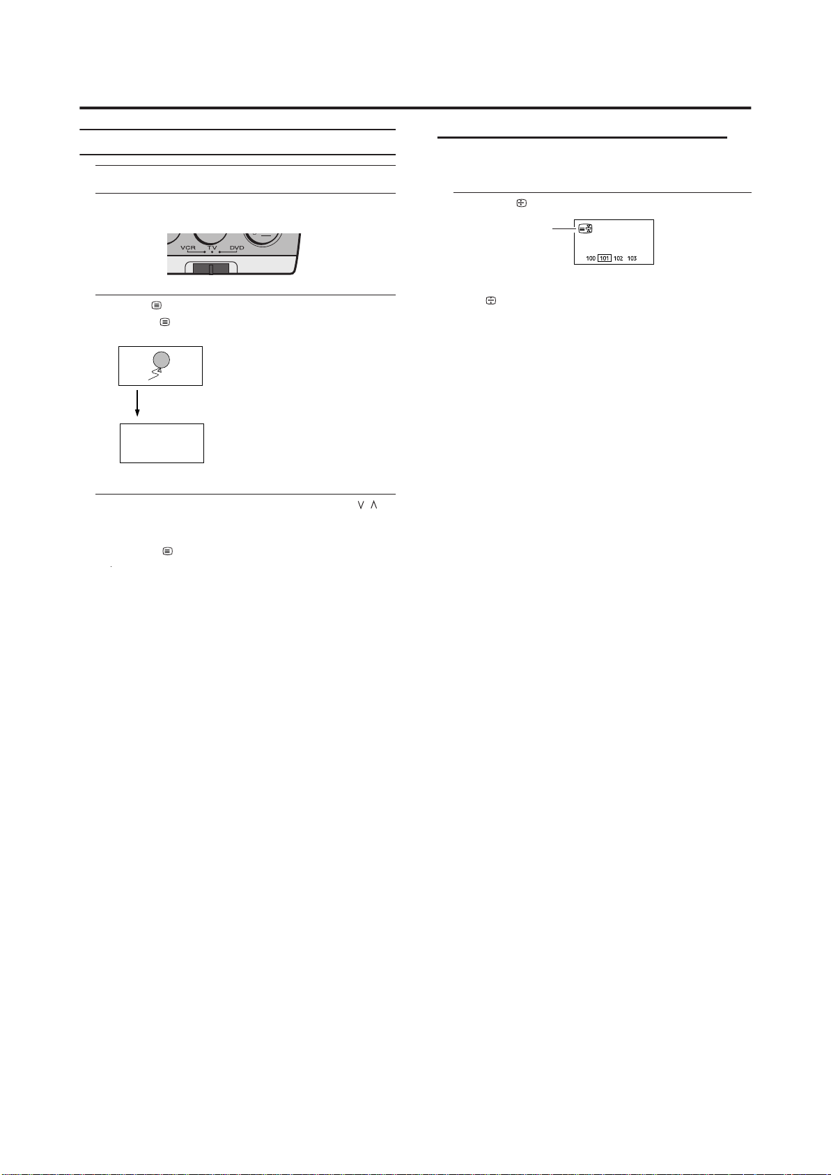
Teletext function
Basic operation
1 Choose a TV channel with a teletext broadcast
Hold
You can hold a teletext page on the screen for as long as
you want, even while several other teletext pages are being
received.
2 Make sure to set the VCR/TV/DVD switch to the
TV position.
3 Press (Text) button to display the teletext
Pressing (Text) button changes the mode as follows:
TV mode
TEXT--TEXT--TEXT---
Text mode
D104 3
4 Choose a teletext page by pressing the P
/
buttons, number buttons or colour buttons
To return to the TV mode:
Press the (Text) button.
• If you have trouble receiving teletext broadcasts,
consult your local dealer or the teletext station.
• The ZOOM function will not work in the TV and text
mode or Text mode.
• You cannot operate menus when viewing a teletext
programme.
• Language display depends on the country which was
set on the COUNTRY menu. If characters on a
Teletext programme do not appear properly, change
the COUNTRY Setting to other country’s.
.
Press the (Hold) button
Hold indication
To cancel the Hold function:
Press (Hold) button again.
15
Page 76

Teletext function
Sub-page
Some teletext pages include sub-pages that are
automatically displayed.
1 Choose a teletext page that includes sub-pages
Press the button, Sub-page numbers can be viewed
and displayed at the screen.
2 Press the number buttons to choose a sub-page
number
Sxxxx : xxxx is the number 0 ~ 9 that you entered.
For example, sub-page 1 is S0001, you must enter 0,0,
0 and 1 serially to view sub-page S0001.
Reveal
Some teletext pages include hidden text (such as the
answers to a quiz).
You can display the hidden text.
Each time you press the (Reveal) button, text is
hidden or revealed
Size
You can double the height of the teletext display.
Cancel
You can search for a teletext page while watching TV.
1 Press the number button to enter a page
number, or press a colour button
The TV searches for a teletext page.
2 Press the (Cancel) button
The TV programme appears. When the TV finds the
teletext page, its page number appears in the upper left
of the screen.
3 Press the (Cancel) button to return to a
teletext page when the page number is on the
screen
• The TV mode cannot be resumed by pressing the
(Cancel) button. To return to the TV mode press
button.
Press the (Size) button.
Index
You can return to the index page instantly.
Press the (Index) button
Returns to page 100 or a previously specified page.
16
Page 77
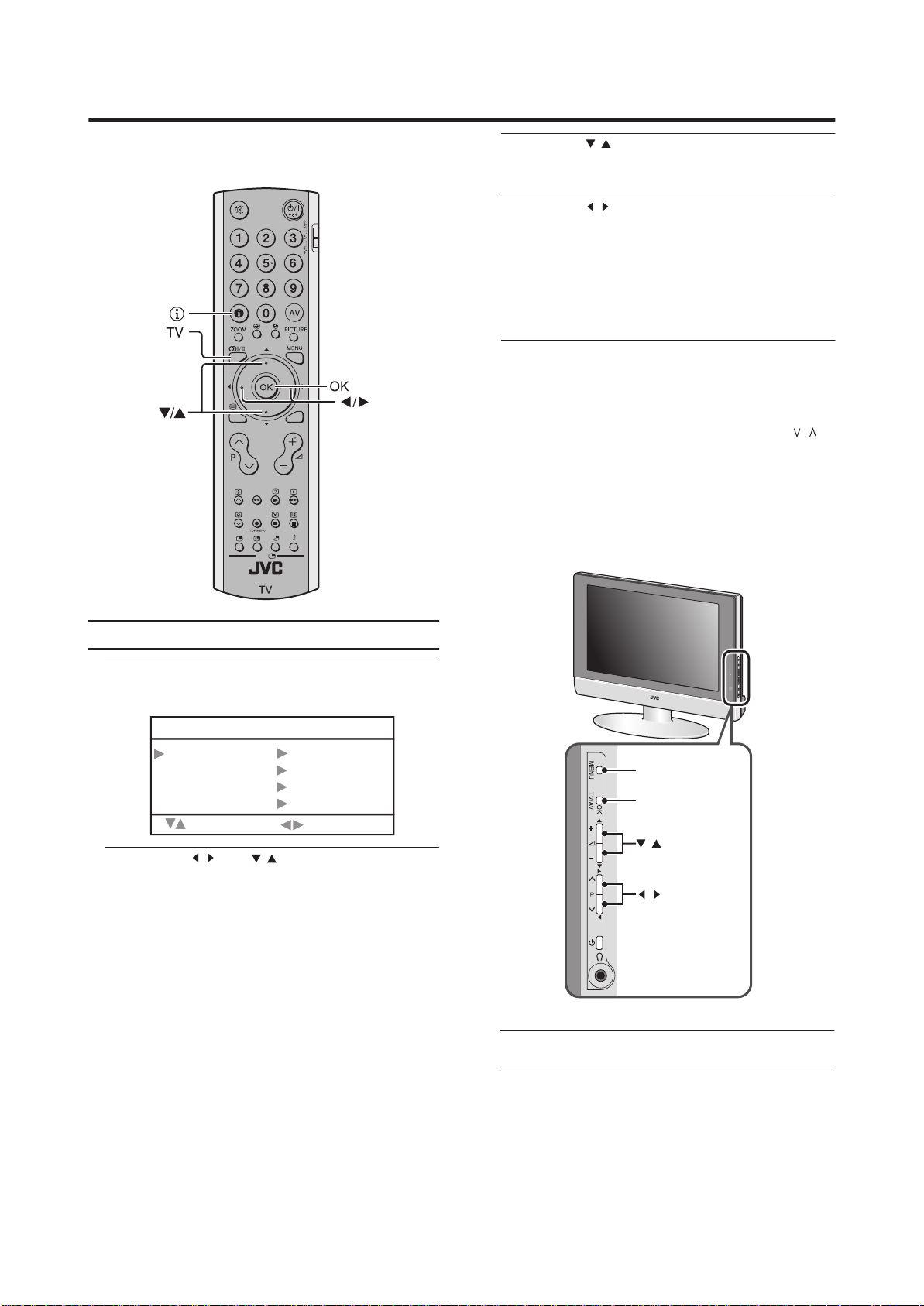
Using the TV’s menu
This TV has a number of functions you can operate using
menus. To use all your TV’s functions, you need to
understand the basic menu operating techniques fully.
BACK
PC
3Press the buttons to choose a function
/
• For details of the functions in the menus, see the
following pages.
4Press the buttons to choose the setting of
/
that function
• If you want to operate a function which appears only
with its name, follow the descriptions of that function
on the following pages.
• The display appearing at the bottom of a menu shows
you a button on the remote control that you can use
when you operate a chosen function.
5Press the
MENU
button to complete the setting
The menu disappears.
• When watching the television with the NTSC system,
the menus are displayed at about half of their normal
vertical size.
• The menu will be disappear if you press the P
/
buttons, the AV button or the number buttons while
the menu is
displayed.
Operation with the buttons on the TV
You can also operate the menus using the buttons on the
front panel of the TV.
Basic operation
1 Press the MENU button to display the MENU (main
menu)
MENU
PICTURE
SOUND
FEATURES
INSTALL
: SELECT :MOVE
2 Press the and buttons to choose a
/
menu title, and press the OK button
The menu appears.
To return to the previous menu:
Press the BACK button on the remote control or the
MENU button on the TV.
To exit
a menu instantly:
Press the MENU button on the remote control or
press the MENU button on the TV several times.
/
MENU button
OK button
buttons
/
buttons
/
The menu will disappear after about one minute if no
operation is performed.
17
Page 78

PICTURE SETTING
Refer to “Using the TV’s menu” (see page 17) for details of
displaying the menu.
PICTURE
PICTURE MODE MANUAL
CONTRAST
BRIGHT-1
SHARP
COLOUR
HUE
BRIGHT-2
COLOUR TEMP NORMAL
RESET
: SELECT
:MOVE
PICTURE MODE
You can choose one of four PICTURE MODEs to adjust
the picture settings automatically.
BRIGHT:
Heightens contrast and sharpness.
STANDARD:
Standardizes picture adjustment.
SOFT:
Softens contrast and sharpness.
MANUAL:
User define.
Picture Adjustment
You can change the picture settings of each PICTURE
MODE mode as you like.
COLOUR TEMP.
You can select one of three COLOUR TEMP. modes (three
tones of white) to adjust the white balance of the picture.
Since white is the colour which is used as a reference for all
the other colours, changing the COLOUR TEMP. mode
affects the appearance of all the other colours on the screen.
COOL:
A bluish white. Using this mode when watching bright
pictures allows you to enjoy a more vivid and bright picture.
NORMAL:
The normal white colour.
WARM:
A reddish white. Using this mode when watching films
allows you to enjoy colours that are characteristic of films.
RESET
You can reset the picture settings you have chosen to the
default settings.
CONTRAST:
You can adjust the picture contrast.
:lower
: higher
BRIGHT-1:
You can adjust the picture brightness.
:darker
: brighter
SHARP:
You can adjust the picture sharpness.
:softer
:sharper
COLOUR:
You can adjust the picture colour.
: lighter
: deeper
HUE:
You can adjust the picture tint.
:reddish
:greenish
BRIGHT-2:
You can adjust the back light.
:darker
:lighter
You can change the HUE setting(picture hue) when the
colour system is NTSC3.58 or NTSC4.43.
18
Page 79

SOUND SETTING
Refer to “Using the TV’s menu” (see page 17) for details of
displaying the menu.
SOUND
BASS
TREBLE
BALANCE
HYPER SOUND OFF
: SELECT
:MOVE
Sound Adjustment
You can adjust the sound to your liking.
BASS:
You can adjust the low tone of the sound.
: weaker
: strong
TREBLE:
You can adjust the high tone of the sound.
: weaker
: strong
BALANCE:
You can adjust the volume balance between the left and
right speaker.
:turn the left speaker’s volume level up.
: turn the right speaker’s volume level up.
HYPER SOUND
You can enjoy Surround sound with a “live” effect by using
the function.
HYPER SOUND
ON:
HYPER SOUND
OFF:
function is turned on.
function HYPER SOUND
is turned off.
19
Page 80

FEATURES
Refer to “Using the TV’s menu” (see page 17) for details of
displaying the menu.
FEATURES
BLUE BACK OFF
CHILD LOCK OFF
EXT-2 OUTPUT TV
: SELECT
BLUE BACK
You can set the TV to automatically change to a blue screen
and mute the sound if the signal is weak or absent, or when
there is no input from an external device.
ON:
This function is turned on.
OFF:
This function is turned off.
CHILD LOCK
When the CHILD LOCK mode is on, the TV buttons will be
locked except Power ON/OFF. TV only can be controled by
remote controller.
:MOVE
EXT-2 OUTPUT
You can choose a signal source to be output from the EXT-2
terminal.
You can do this with the output signals of the devices
connected to EXT-1 termainal, or with the picture and
sound from a TV channel you are currently viewing.
Press the buttons to choose the
signal source TV/EXT-1.
• EXT-3 terminal can not be output.
/
2 0
Page 81

INSTALL
Refer to “Using the TV’s menu” (see page 17) for details of
displaying the menu.
In TV mode :
INSTALL
MANUAL
PROGRAM
: SELECT OK : MOVE
In EXT mode :
INSTALL
COLOUR SYSTEM
:
SELECT
AUTO
:MOVE
MANUAL
You can store the TV channel for which you needed.
Store them in the TV’s program numbers list
by setting the following.
MANUAL
PROGRAM 01
BAND CH
CHANNEL 02
COLOUR SYSTEM AUTO
SOUND SYSTEM AUTO
SEARCH
FINE TUNING
STORE
: SELECT : MOVE
PROGRAM
AUTO PROGRAM
You can automatically store the TV channels for which you
have the best reception. Store them in the TV’s program
numbers list by doing the following.
Choose PROGRAM. Then press the OK button.
1
PROGRAM
01 ---02 ---03 ---04 ---05 ---06 ---07 ---08 ---09 ---10 ----
N
INSERT A.P.S.
11 ---12 ---13 ---14 ---15 ---16 ---17 ---18 ---19 ---20 ----
ME DELETE
A
2 Press the blue button, AUTO PROGRAM menu
appears.
AUTO PROGRAM
LANGUAGE ENGLISH
COUNTRY UK
A. P. S.
:
SELECT
21 ---22 ---23 ---24 ---25 ---26 ---27 ---28 ---29 ---30 ----
:MOVE
1 Select PROGRAM and press the buttons to
/
choose the program number.
2 Select BAND and press the buttons to
/
choose the band type.
CH(AIR) / CC(CATV)
3 Select CHANNEL and press the buttons to
/
choose the channel number.
4 Select COLOUR SYSTEM and press the
/
buttons to choose the colour system.
AUTO / PAL / SECAM
• If you do not have a clear picture or no colour appears,
change the colour system.
5 Select SOUND SYSTEM and press the
/
buttons to choose the sound system.
AUTO / B/G / D/K / L / I
• If the SOUND SYSTEM setting for a TV channel is
incorrect, it may provent the sound from being issued.
6 Select SEARCH and press the buttons to
/
choose the serviceable TV channel.
7 If the channel reception is poor, select
FINE TUNING and press the buttons to
/
fine tune the program.
8 Select Store and press the buttons to
/
store the manual setting.
3
P
ress
/
he buttons to choose the
t
LANGUAGE.
4
P
ress
/
t
he buttons to choose the
ENGLISH.
The on-screen display will then be in English.
5
P
ress
country where you are.
/
he and buttons to choose the
t
/
6
P
ress
Th
en press the buttons.
/
he buttons to choose the A.P.S.
t
A.P.S.
START
OK : START
/
7
P
he OK button to start the A.P.S.
ress
t
A.P.S.
A.P.S. IS RUNNING
MENU : EXIT
The AUTO PROGRAM menu appears and received TV
channels are automatically stored in the programme
numbers.
• To cancel the AUTO PROGRAM function:
Press the MENU button.
21
Page 82

INSTALL
After the TV channels have been registered in
the programme numbers, the PROGRAM menu
appears
• If you want to, you can now edit the program
numbers using the PROGRAM function.
For details, see “To edit theP ROGRAM menu”
on page 22.
To edit the PROGRAM menu
You can edit the programme numbers.
Caution
• Using the NAME, DELETE or INSERT functions
rewrites the current programme numbers list.
Therefore, the programme nu of some of
the TV channels will change.
1 Choose PROGRAM, then press the OK button
PROGRAM
01 ---02 ---03 ---04 ---05 ---06 ---07 ---08 ---09 ---10 ----
N
AME DELETE
INSERT A.P.S.
2 Follow the operation description of a function
you want to use and operate the function
NAME:
This function registers a channel name (ID) to a TV
channel.
INSERT:
This function changes a programme number of a
TV channel.
DELETE:
This function deletes a TV channel you do not want to
list.
A.P.S:
This function received TV channels automatically
amnd stored in program numbers. For details,
see "AUTO PROGRAM" on page 21.
11 ---12 ---13 ---14 ---15 ---16 ---17 ---18 ---19 ---20 ----
mber
21 ---22 ---23 ---24 ---25 ---26 ---27 ---28 ---29 ---30 ----
NAME
1Press t
he and buttons to choose a TV
/
channel
Every time you press the buttons, the
programme number changes and the picture of the
TV channel stored in the programme number appears
on the screen.
2Press the red button to start the NAME function
PROGRAM
01 ---02 ----
03 ---04 ---05 ---06 ---07 ---08 ---09 ---10 ----
STORE
CANCEL
3Press th e buttons
/
channel name you want to give the TV channel
PROGRAM
01 ---02
BBC1
03 ---04 ---05 ---06 ---07 ---08 ---09 ---10 ----
STORE
CANCEL
4 Press the red button to store the setting
PROGRAM
01 ---02
BBC1
03 ---04 ---05 ---06 ---07 ---08 ---09 ---10 ----
NAME DELETE
INSERT A.P.S.
/
and
/
11 ---12 ---13 ---14 ---15 ---16 ---17 ---18 ---19 ---20 ----
/
and
11 ---12 ---13 ---14 ---15 ---16 ---17 ---18 ---19 ---20 ----
11 ---12 ---13 ---14 ---15 ---16 ---17 ---18 ---19 ---20 ----
/
21 ---22 ---23 ---24 ---25 ---26 ---27 ---28 ---29 ---30 ----
to edit the
21 ---22 ---23 ---24 ---25 ---26 ---27 ---28 ---29 ---30 ----
21 ---22 ---23 ---24 ---25 ---26 ---27 ---28 ---29 ---30 ----
22
To return to the INSTALL menu:
Press the BACK button.
To exit
a menu instantly:
Press the MENU button.
Page 83

INSTALL
INSERT
1Press t
he and buttons to choose a
/
program number for which you want
Every time you press the buttons, the
programme number changes and the picture of the
TV channel stored in the programme number appears
on the screen.
PROGRAM
01 ---02
BBC1
03
BBC2
04 ---05 ---06 ---07 ---08 ---09 ---10 ----
NAME
INSERT A.P.S.
2 Press the green button to start the INSERT
function
/
and
/
11 ---12 ---13 ---14 ---15 ---16 ---17 ---18 ---19 ---20 ----
DELETE
/
21 ---22 ---23 ---24 ---25 ---26 ---27 ---28 ---29 ---30 ----
4 Press the green button to insert the channel into
the new program number
PROGRAM
BBC2
BBC1
11 ---12 ---13 ---14 ---15 ---16 ---17 ---18 ---19 ---20 ----
01 ---02 ---03
04
05 ---06 ---07 ---08 ---09 ---10 ----
NAME DELETE
21 ---22 ---23 ---24 ---25 ---26 ---27 ---28 ---29 ---30 ----
INSERT A.P.S.
To return to the INSTALL menu:
Press the BACK button.
To exit
a menu instantly:
Press the MENU button.
ENGLISH
PROGRAM
01 ---02
03
04 ---05 ---06 ---07 ---08 ---09 ---10 ----
3Press t
he and buttons to choose a new
program number
PROGRAM
01 ---02
03
04 ---05 ---06 ---07 ---08 ---09 ---10 ----
BBC1
BBC2
11 ---12 ---13 ---14 ---15 ---16 ---17 ---18 ---19 ---20 ----
21 ---22 ---23 ---24 ---25 ---26 ---27 ---28 ---29 ---30 ----
INSERT CANCEL
/
BBC1
BBC2
/
11 ---12 ---13 ---14 ---15 ---16 ---17 ---18 ---19 ---20 ----
21 ---22 ---23 ---24 ---25 ---26 ---27 ---28 ---29 ---30 ----
INSERT CANCEL
2 3
Page 84

INSTALL
DELETE
1Press t
he and buttons to choose a
/
program number for which you want
Every time you press the buttons, the
programme number changes and the picture of the
TV channel stored in the programme number appears
on the screen.
PROGRAM
01 ---02
BBC1
03
BBC2
04 ---05 ---06 ---07 ---08 ---09 ---10 ----
NAME
INSERT A.P.S.
2 Press the yellow button to start DELETE
function
PROGRAM
01 ---02
BBC1
03
BBC2
04 ---05 ---06 ---07 ---08 ---09 ---10 ----
/
and
/
11 ---12 ---13 ---14 ---15 ---16 ---17 ---18 ---19 ---20 ----
DELETE
11 ---12 ---13 ---14 ---15 ---16 ---17 ---18 ---19 ---20 ----
DELETE
CANCEL
/
21 ---22 ---23 ---24 ---25 ---26 ---27 ---28 ---29 ---30 ----
21 ---22 ---23 ---24 ---25 ---26 ---27 ---28 ---29 ---30 ----
COLOUR SYSTEM in EXT mode
Press t
he buttons to choose the colour system
/
When you are in EXT mode, you can only change the
colour system in the INSTALL menu.
3 Press the yellow button to delete the selected
TV channel
The TV channel is deleted from the programme numbers
list.
PROGRAM
01 ---02
BBC1
----
03
04 ---05 ---06 ---07 ---08 ---09 ---10 ----
NAME
11 ---12 ---13 ---14 ---15 ---16 ---17 ---18 ---19 ---20 ----
DELETE
21 ---22 ---23 ---24 ---25 ---26 ---27 ---28 ---29 ---30 ----
INSERT A.P.S.
To return to the INSTALL menu:
Press the BACK button.
To exit
a menu instantly:
Press the MENU button.
24
Page 85

PC MENU (In PC mode only)
This TV also has a number of functions on PC mode,
you can operate using pc menus.
PC MENU
PC PICTURE POSITION
PC PICTURE
SOUND
: SELECT
1024 X 768
H : 48 kHz
OK : OK
V : 60 Hz
PC PICTURE POSITION
You can adjust the picture settings as following functions.
PC PICTURE POSITION
AUTO SETUP
H POSITION
V POSITION
CLOCK
PHASE
RESET
: SELECT
:MOVE
AUTO SETUP:
You can adjust picture settings automatically for optimized
picture position, clock and phase.
H POSITION:
You can adjust picture horizontal position.
:left
: right
V POSITION:
You can adjust picture vertical position.
:down
: up
CLOCK:
You can adjust CLOCK to fine tune picture.
PHASE:
You can adjust PHASE to fine tune picture.
RESET:
You can select RESET for default setting.
PC PICTURE
You can change the picture settings of each PICTURE
MODE mode as you like.
PC PICTURE
CONTRAST
BRIGHT-2
COLOUR TEMP. MANUAL
R
G
B
RESET
: SELECT
CONTRAST:
You can adjust the picture contrast.
:lower
: higher
BRIGHT-2:
You can adjust the back light.
:darker
:lighter
:MOVE
COLOUR TEMP.:
You can adjust the picture colour mode.
COOL:
A bluish white. Using this mode when watching bright
pictures allows you to enjoy a more vivid and bright picture.
NORMAL:
The normal white colour.
WARM:
A reddish white. Using this mode when watching films
allows you to enjoy colours that are characteristic of films.
MANUAL:
User defined.
R:
You can adjust the Red color component.
:reddish
: redder
G:
You can adjust the Green color component
:greenish
:greener
B:
You can adjust the Blue color component.
:blueish
:bluer
RESET:
You can select RESET for default setting.
SOUND
You can adjust the sound to your liking.
SOUND
BASS
TREBLE
BALANCE
HYPER SOUND OFF
: SELECT
BASS:
You can adjust the low tone of the sound.
: weaker
: strong
TREBLE:
You can adjust the high tone of the sound.
:weaker
: strong
BALANCE:
You can adjust the volume balance between the left and
right speaker.
:turn the left speaker’s volume level up.
: turn the right speaker’s volume level up.
HYPER SUOUND:
You
joy Surround sound with a “live” effect by using
can en
the HYPER SOUND functions.
ON:
HYPER SOUND
OFF:
HYPER SOUND
function is turned on.
function is turned off.
:MOVE
25
Page 86

PC MENU
PC support mode list
Mode NO. Mode Name
1
2
3
4
5
The resolution and the freauencies which are
displayed on the screen may not exactly same as
this list.
The Auto SETUP functions will work automatically
when you change the resolution of PC mode. The
picture position, clock, and phase will be optimized.
Resolution
VGA 60 Hz
640x480
SVGA 60 Hz
800x600
SVGA 60 Hz
800x600
XGA 60 Hz
1024x768
WXGA
1280x768
H Freq. (kHz)
V Freq. (Hz)
31.469
59.941
35.16
56.25
37.879
60.317
48.363
60.004
47.73
60
266
Page 87

Additional preparation
Connecting external equipment
Connect the equipment to the TV, making the correct rear
panel and front panel connections.
Before connecting anything:
• Read the manuals that came with the equipment.
Depending on the equipment, the connection method
may be different from the diagram. Also, the equipment
settings may need to change depending on the
connection method.
• Turn off all the equipment including the TV.
• The “Specifications” on page 31 give the details of the
EXT terminals. If you are connecting equipment not
listed in the following connection diagram, see the table
to choose the best EXT terminal.
• Connecting cables are not supplied.
• To connect the PC, please see "Connecting the PC" on
page 28.
1 VCR (composite signal)
2 VCR (composite signal/S-VIDEO signal)
3 T-V LINK compatible VCR (composite signal/S-VIDEO
signal)
4 Decoder
5 DVD player (composite signal/S-VIDEO signal)
6 DVD player (composite signal/RGB signal)
7
PC
8 TV game (composite signal/RGB signal)
9 TV game (composite signal/S-VIDEO signal)
10 Headphones
11 Camcorder (composite signal/S-VIDEO signal)
12 SCART cable
13 Audio in
PC
14 Video cable
15 S-VIDEO cable
16 D-SUB in
twithou terminal covers
PC AUDIO IN
L
R
SUBWOOFER
27
Page 88

Additional preparation
Equipment which can output the S-VIDEO
signal (Y/C signal) such as an S-VHS VCR
Connect the equipment to an EXT terminal (but not the
EXT-1 terminal).
You can choose between an S-VIDEO signal (Y/C signal).
Connecting headphones
Connect the headphones with a stereo mini-jack (3.5 mm
diameter) to the headphone socket at the TV.
Video or sound signal output from the EXT-2
terminal
You can change over the output of the video/sound signal
from the EXT-2 terminal. This is useful when you want to
dub the video/sound from another device onto the VCR
connected to the EXT-2 terminal.
TV output from the EXT-1 terminal
The video/sound signal of a TV channel you are viewing is
always output from the EXT-1 terminal.
• Changing over a programme number also changes
over the TV output from the EXT-1 terminal.
• The video/sound signal from an EXT terminal cannot be
output.
• Teletext programmes cannot be output.
Connecting the PC
Connect the PC with the D-SUB cable to the D-SUB in at
the TV, and connect the sound device of PC with a stereo
mini-jack to PC AUDIO IN.
You can adjust the picture by AUTO SETUP function when
the PC signal is output correctly, the AUTO SETUP function
can optimize the picture position, clock and phase. You can
have a fine vision after AUTO SETUP function executed.
Connecting Speakers/Amplifier
See the Audio equipment connection diagram, then connect
the audio equipment you desire to the TV.
You can use external front speakers to listen to the TV
sound instead of the TV speakers.
Before connecting anything:
• Read the manuals provided with the amplifier and
speakers.
• Turn the TV and amplifier off.
• To prevent magnetism from the speakers adversely
affecting the TV screen, use magnetically-shielded
speakers for the front speakers.
• Note that connecting cables are not supplied.
without terminal covers
L
R
SUBWOOFER
PC AUDIO IN
SUBWOOFER
L
R
1 Amplifier
2 External speakers (Magnetic-shielded type)
• The output from the AUDIO OUT terminal is not
interrupted by headphone connection to the TV. You
cannot cut the sound from the front speaker even if you
connect a headphone to the TV.
• Adjust the volume of the external speakers with the
amplifier.
• Connect the subwoofer which carried an amplifier.
• The subwoofer is interlocked with the TV volume.
28
Page 89

Troubleshooting
If a problem arises while you are using the TV, please read this troubleshooting guide carefully before you ask to have the TV
repaired. You may be able to fix it easily by yourself. For example, if the mains plug is disconnected from the mains outlet, or the
TV aerial has problems, you may think there is a problem with the TV itself.
Important:
• This troubleshooting guide only covers problems whose causes are not easy to decide. If you have a question when you are
operating a function, read the page(s) for that function carefully, not this troubleshooting guide.
• If you follow the advice in this troubleshooting guide without any success, unplug the mains plug and ask for your TV to be
repaired. Do not attempt to repair the TV by yourself or to remove the rear cover of the TV.
If you cannot turn on the TV
• Are the AC plug on the power cord from the TV is
connected to AC outlet?
• Make sure to set the VCR/TV/DVD switch to the TV
position. You cannot turn the TV on when the VCR/TV/
DVD switch is set to the VCR or DVD position.
If you cannot turn off the TV
• Make sure to set the VCR/TV/DVD switch to the TV
position. You cannot turn the TV off when the VCR/TV/
DVD switch is set to the VCR or DVD position.
No picture or no sound
• Have you chosen a TV channel with very poor
reception? If so, the BLUE BACK function will be
activated: the entire screen becomes blue, and the sound
is muted. If you still want to view the TV channel,
follow the description “BLUE BACK” on page 20 to
change the BLUE BACK function setting to OFF.
• If the SOUND SYSTEM setting for a tTV channel is
incorrect, it may prevent the sound from being issued.
Follow the description “INSTALL” on page 21 to use the
MANUAL function to try to change the SOUND SYSTEM
setting.
Poor picture
• If noise (snow) totally blocks out the picture, there may
be a problem with the aerial or aerial cable. Check the
following to try to solve the problem:
–Have the TV and aerial been connected properly?
–Has the aerial cable been damaged?
–Is the aerial pointing in the right direction?
–Is the aerial itself faulty?
• If the TV or aerial suffers interference from other
equipment, stripes or noise may appear in the picture.
Move any equipment such as an amplifier, personal
computer, or a hair drier, that can cause interference
away from your TV. Or try moving the TV. If the aerial
suffers interference from a radio tower or high-voltage
wire, please contact your local dealer.
• If the TV suffers interference from signals reflecting
from mountains or buildings, double-pictures (ghosting)
will occur. Try to change the aerial’s direction or replace
it with one with better directionality.
• Have the COLOUR and BRIGHT settings been adjusted
properly? Follow the description “Picture Adjustment”
on page 18 to try to adjust them properly.
• Videotaping teletext is not recommended because it may
not record correctly.
• When viewing images from commercially available
video software products, or videos from videotapes
which have been recorded improperly, the top of the
image may be distorted. This is due to the condition of
the video signal. There is nothing wrong with the TV.
Poor sound
• Have you adjusted BASS or TREBLE properly? If not,
follow the description “Sound Adjustment” on page 19.
If the TV does not respond to the remote
control
• Have the batteries of the remote control worn out?
Follow the description “Putting the batteries into the
Remote control” on page 5 and replace them with new
batteries.
• Have you attempted to use the remote control from the
sides or rear of the TV or from more than seven metres
away from the TV? Use the remote control in the front of
your TV or from less than seven metres away.
• When you are viewing a teletext programme, you cannot
operate the menus. Press the button to return to the
ordinary TV programme, and then try operating the
menus.
• If the TV suddenly stops responding, disconnect the
power cord of the TV from the AC outlet.
Connect them to the AC outlet again to turn on the TV.
If the TV returns to a normal state, it is not a failure.
29
Page 90

Other concerns
• When the SLEEP TIMER function operates, the TV is
automatically turned off. If the TV suddenly turns off,
try to press the (standby) button to turn on the TV
once again. If the TV goes back to normal, there is no
problem.
• When the TV is receiving a wide-screen signal (WSS) or
a signal from an external device affecting the screen
size, the ZOOM mode automatically changes. When you
want to resume the previous ZOOM mode, press the
button again.
ZOOM
• It takes a short period of time from the time an operation
such as changing channels is performed until an image is
displayed. This is not a malfunction. This is the time
required for the image to stabilize before it can be
displayed.
• The TV may make a crackling sound due to a sudden
change in temperature. The picture or sound may be
normal. If you hear crackling sounds frequently while
you are viewing the TV, there may be other causes. As a
precaution, ask your service technician to inspect it.
• In the twin pictures mode the sub-picture may disappear
when the external device is operated. If this happens,
press the button and display the sub-picture again.
• The top of the TV and the screen may become hot during
use but this has no affect on the performance of the TV.
Ensure that the ventilation holes are not blocked.
• When the picture is unstable, the screen may become
white for a moment. This occurs when the signal which
drives the liquid crystal is missing. This is not a
malfunction.
• When a still image has been displayed for a long period,
a faint residual image may remain on the screen for a
short time after the power has been turned off or when
another image is displayed. This is not a malfunction and
the image will eventually disappear.
• When the correct picture has not been displayed on screen,
the following error messages will display on screen.
NO SIGNAL - TV recived no signal from PC, you may
check your PC is working correctly or not.
CABLE NO INPUT - The cable is not connected correctly.
Ensure that the cable is connected correctly.
OUT OF RANGE - The picture resolution is out of limit.
Ensure that the PC picture resolution is set correctly.
Troubleshooting
30
Page 91
Specifications
Item
Broadcasting systems CCIR B/G, I, D/K, L
Colour systems PAL, SECAM
Channels and frequencies • E21-E69, IR A-J
Sound-multiplex systems A2 (B/G, D/K), NICAM (B/G, I, D/K, L) system
Teletext systems FLOF (Fastext), TOP, WST (World Standard System)
Power requirements TV : 12V DC, AC adapter : 100 - 240 V AC, 50/60 Hz
Power consumption 60 W, Standby: 6 W
Screen size Viewable area 43.5 cm (measured diagonally)
Display resolution 1280 x 768 (W-XGA)
Audio output Rated Power output: 3 W + 3 W
Speakers 5.4 cm round x 2
EXT-1 terminal Euroconnector (21-pin, SCART)
EXT-2 terminal Euroconnector (21-pin, SCART)
EXT-3 terminal
AUDIO OUT terminal
PC INPUT terminal Analog RGB:D-SUB (15 pins) x 1, PC AUDIO IN x 1
Headphone jack Stereo mini-jack (3.5 mm in diameter)
Model
• The EXT terminals also support the NTSC 3.58/4.43 MHz system.
• Video input, Audio L/R inputs and RGB inputs are available.
• TV broadcast outputs (Video and Audio L/R) are available.
• Video input, S-VIDEO (Y/C) input, Audio L/R inputs and RGB inputs are available.
• Video and Audio L/R outputs are available.
RCA connectors x 3, S-VIDEO connector x 1
• Video input, S-VIDEO(Y/C) and Audio L/R inputs are available.
RCA connectors x 3
• Audio L/R outputs and a subwoofer output are available.
• PC signal and audio inputs are available.
LT-17E75BJG/LT-17E75SJG
Dimensions (W H D) 465 mm x 325 mm x 78 mm(TV only)
Weight 6.1kg(TV only)
Accessories Remote control unit x 1
465 mm x 363 mm x 190 mm
7.3kg
AA/R6 dry cell battery x 2
(RM-C1860)
AC adapter x 1 (HP-OL060D03)
Power cord x 1
Design and specifications subject to change without notice.
Pictures displayed on the screen using this TV’s ZOOM functions should not be shown for any commercial or demonstration purpose
in public places (cafes, hotels, etc.) without the consent of the owners of copyright of the original picture sources, as this constitutes an
infringement of copyright.
31
Page 92

5
© 2003 VICTOR COMPANY OF JAPAN, LIMITED
5030057025
1003-MK-TU
Page 93

SCHEMATIC DIAGRAMS
LCD FLAT TELEVISION
LT-17E31 BUG/BJG
LT-17E31 SUG/SJG
LT-17E75 BJG
LT-17E75 SJG
CD-ROM No. SML200406
COPYRIGHT © 2004 Victor of Japan, Limited
No.YA031
2004/6
Page 94

LT-17E31BUG, LT-17E31BJG, LT-17E75BJG
LT-17E31SUG, LT-17E31SJG, LT-17E75SJG
STANDARD CIRCUIT DIAGRAMS
CONTENTS
USING P.W. BOARD .....................................................................................................................................................................2-1
SEMICONDUCTOR ........................................................................................................................................................................ 2-1
BLOCK DIAGRAM ......................................................................................................................................................................... 2-2
CIRCUIT DIAGRAMS ................................................................................................................................................................... 2-3
MAIN PWB CIRCUIT DIAGRAM ........................................................................................................................................................... 2-3
IR SENSOR PWB CIRCUIT DIAGRAM .............................................................................................................................................. 2-25
AV JACK PWB CIRCUIT DIAGRAM ................................................................................................................................................... 2-27
FRONT CONTROL PWB CIRCUIT DIAGRAM ................................................................................................................................... 2-29
TUNER PWB CIRCUIT DIAGRAM ...................................................................................................................................................... 2-31
PATTERN DIAGRAMS............................................................................................................................................................... 2-33
MAIN PWB PATTERN .........................................................................................................................................................................2-33
IR SENEOR PWB PATTERN .............................................................................................................................................................. 2-35
AV JACK PWB PATTERN ................................................................................................................................................................... 2-35
FRONT CONTROL PWB PATTERN ................................................................................................................................................... 2-35
TUNER PWB PATTERN ...................................................................................................................................................................... 2-35
USING P.W. BOARD
MAIN P.W. BOARD DA-5097627803 (PWB-0640-1)
IR SENSOR P.W. BOARD DA-5097627803 (PWB-0640-2)
AV JACK P.W. BOARD DA-5098800654 (PWB-0641-1)
FRONT CONTROL P.W. BOARD DA-5098800659 (PWB-0641-2)
TUNER P.W. BOARD DA-5098800653 (PWB-0641-3)
SEMICONDUCTOR SHAPES
TRANSISTOR
BOTTOM VIEW
E
C
B
ECB
IC
B OT TO M V I EW FR O NT V I EW T OP V I EW
OUT
E
IN
IN OUTE
BCE
(G)(D)(S )
FRONT VI EW
1 N
ECB
ECB
1 N
TOP VIEW
CHIP TR
1
C
BE
N
CHIP IC
TOP VIEW
N
N
N
1
N
1
N
(No. YA031) 2-1
Page 95
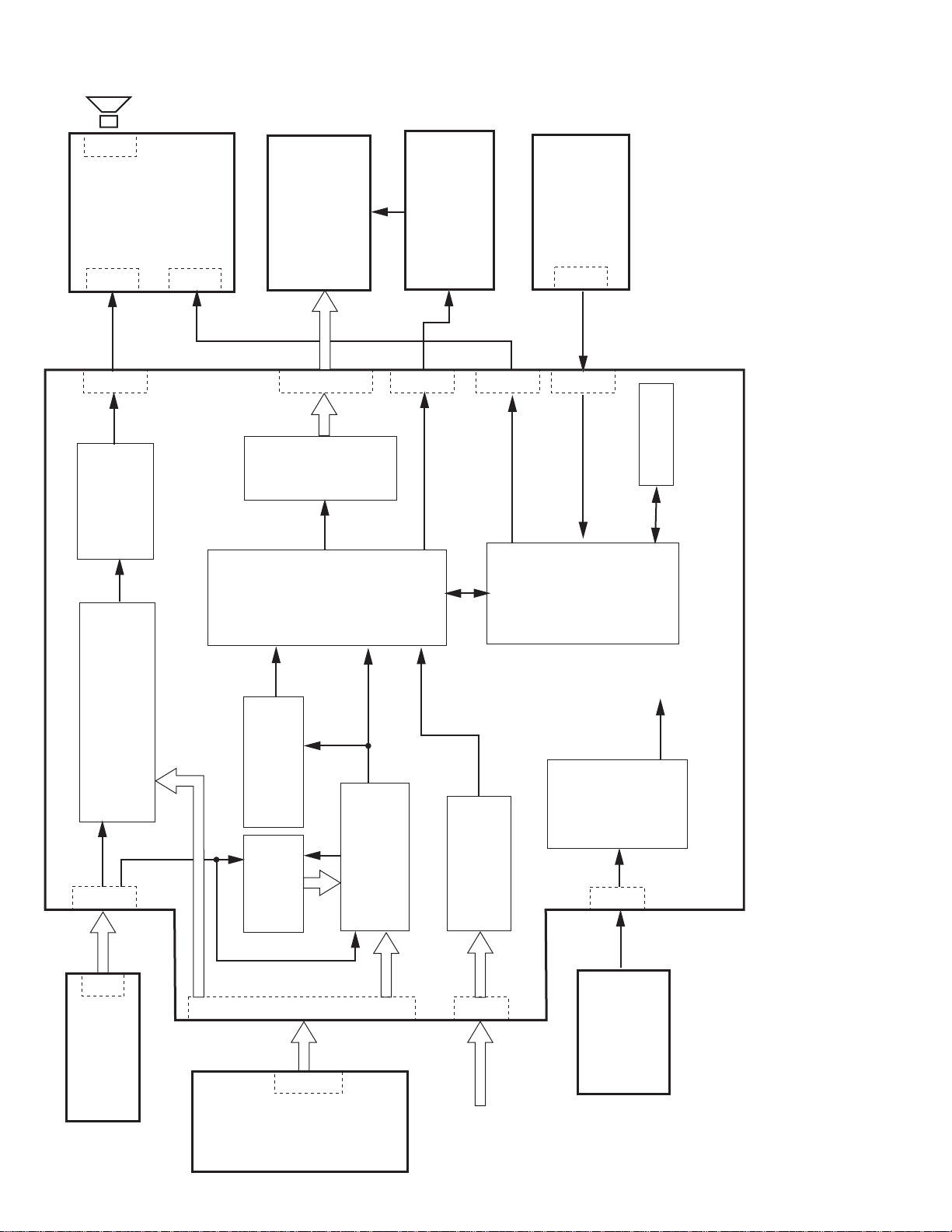
BLOCK DIAGRAM
3W+3W
P603
(Speaker)
I008
Audio amp
PWB
(Headphone)
Front Control
P604
P604P602
(TPA1517)
I034
I036
LCD Panel
P008P005
24bit
TP6760
Scaler
Port B(Main )
Inverter PWB
P007 P003
THC63LVDM83A
P002
LVDS I/F
Port V(SUb)
Port A(Main)
PWB
IR Sensor
P601
Micro
(STK6012)
Controller
PROM
2
E
I004
Main PWB
I033
(MSP3415G)
Audio Processor
&
MTS
TV
(Audio)
P012
PT17
Tuner PWB
Scart1,2 Audio
AV,SV Audio
PC Audio
I031
TV
(Video)
I016
I030
FSW
H,V
RGB
P006
8bit
24bit
(SiI504)
De-Interlace
Teletext
(SAA5264)
P001
24bit
I013
(SAA7118)
Video decoder
ADC
(AD9883A-140)
PJ01
12V
8V
5V
3.3V
2.5V
Power
Supply
P009
12V
AC
adapter
PWB
AV Jack
EXT-1
(Scart1)
EXT-2
(Scart2)
EXT-3
(AV, SV)
No. YA0312-2
VGA
50/60Hz
110/220V
Page 96

Power save
DC IN
(12V)
17"
(NC)
Sheet 2,6,9,10
MAIN PWB ASS'Y (1/11)
MAIN PWB CIRCUIT DIAGRAM (1/11)
CIRCUIT DIAGRAMS
No. YA031
2-3 2-4
No. YA031
Page 97

Sheet 3
Sheet 8
MPU
Sheet 5,7
Sheet 8
Sheet 8
Sheet 8
Sheet 5
Sheet 1,6,9,10
Sheet 3,4,5,6,7,10
Sheet 4
Sheet 7
Sheet 10,11
FRONT CONTROL PWB
P602
IR SENSOR PWB
P601
MAIN PWB ASS'Y (2/11)
MAIN PWB CIRCUIT DIAGRAM (2/11)
No. YA031
2-5 2-6
No. YA031
Page 98

A/D CONVERTER
Sheet 8
Sheet 8
Sheet 2
MAIN PWB ASS'Y (3/11)
Sheet 8
MAIN PWB CIRCUIT DIAGRAM (3/11)
No. YA031 2-7 2-8
No. YA031
Page 99

Sheet 6 Sheet 6
Sheet 6
Sheet 6
Sheet 10
Sheet 10
Sheet 6
Sheet 6
Sheet 6
Sheet 6
Sheet 6
Sheet 2
Sheet 6
Sheet 6
Sheet 6
MAIN PWB ASS'Y (4/11)
TUNER PWB PT17
AV JACK PWB
P001
MAIN PWB CIRCUIT DIAGRAM (4/11)
No. YA031
2-9 2-10
No. YA031
Page 100

Sheet 4
Sheet 6
Sheet 6
Sheet 6
Sheet 6
Sheet 2,3,4,6,7,10
Sheet 2
TELE TEXT
MAIN PWB ASS'Y (5/11)
MAIN PWB CIRCUIT DIAGRAM (5/11)
No. YA031 2-11 2-12
No. YA031
 Loading...