

JVC KW-XG700J, KW-XG704UI, KW-XG701EY, KW-XG701EX, KW-XG705U Service Manual
...
SERVICE MANUAL
CD RECEIVER
MA34620076SERVICE MANUAL
KW-XG700J, KW-XG701E, KW-XG701EX,
KW-XG701EY, KW-XG701EU, KW-XG704UI,
KW-XG705U, KW-XG705UN, KW-XG705UH,
KW-XG706U, KW-XG706UN, KW-XG706UH,
KW-XG707EE, KW-XG708UF
COPYRIGHT © 2007 Victor Company of Japan, Limited
KW-XG700 KW-XG700
* Please refer to the mechanism manual (model TN2007-1010 (No.MY005 and No.MY005B)) for the CD mechanism.
Lead free solder used in the board (material : Sn-Ag-Cu, melting point : 219 Centigrade)
Lead free solder used in the board (material : Sn-Cu, melting point : 230 Centigrade)
1 PRECAUTION. . . . . . . . . . . . . . . . . . . . . . . . . . . . . . . . . . . . . . . . . . . . . . . . . . . . . . . . . . . . . . . . . . . . . . . . . 1-7
2 SPECIFIC SERVICE INSTRUCTIONS . . . . . . . . . . . . . . . . . . . . . . . . . . . . . . . . . . . . . . . . . . . . . . . . . . . . . 1-10
3 DISASSEMBLY . . . . . . . . . . . . . . . . . . . . . . . . . . . . . . . . . . . . . . . . . . . . . . . . . . . . . . . . . . . . . . . . . . . . . . 1-11
4 ADJUSTMENT . . . . . . . . . . . . . . . . . . . . . . . . . . . . . . . . . . . . . . . . . . . . . . . . . . . . . . . . . . . . . . . . . . . . . . . 1-15
5 TROUBLESHOOTING . . . . . . . . . . . . . . . . . . . . . . . . . . . . . . . . . . . . . . . . . . . . . . . . . . . . . . . . . . . . . . . . . 1-16
COPYRIGHT © 2007 Victor Company of Japan, Limited
KW-XG701
KW-XG707
TABLE OF CONTENTS
No.MA346
2007/6

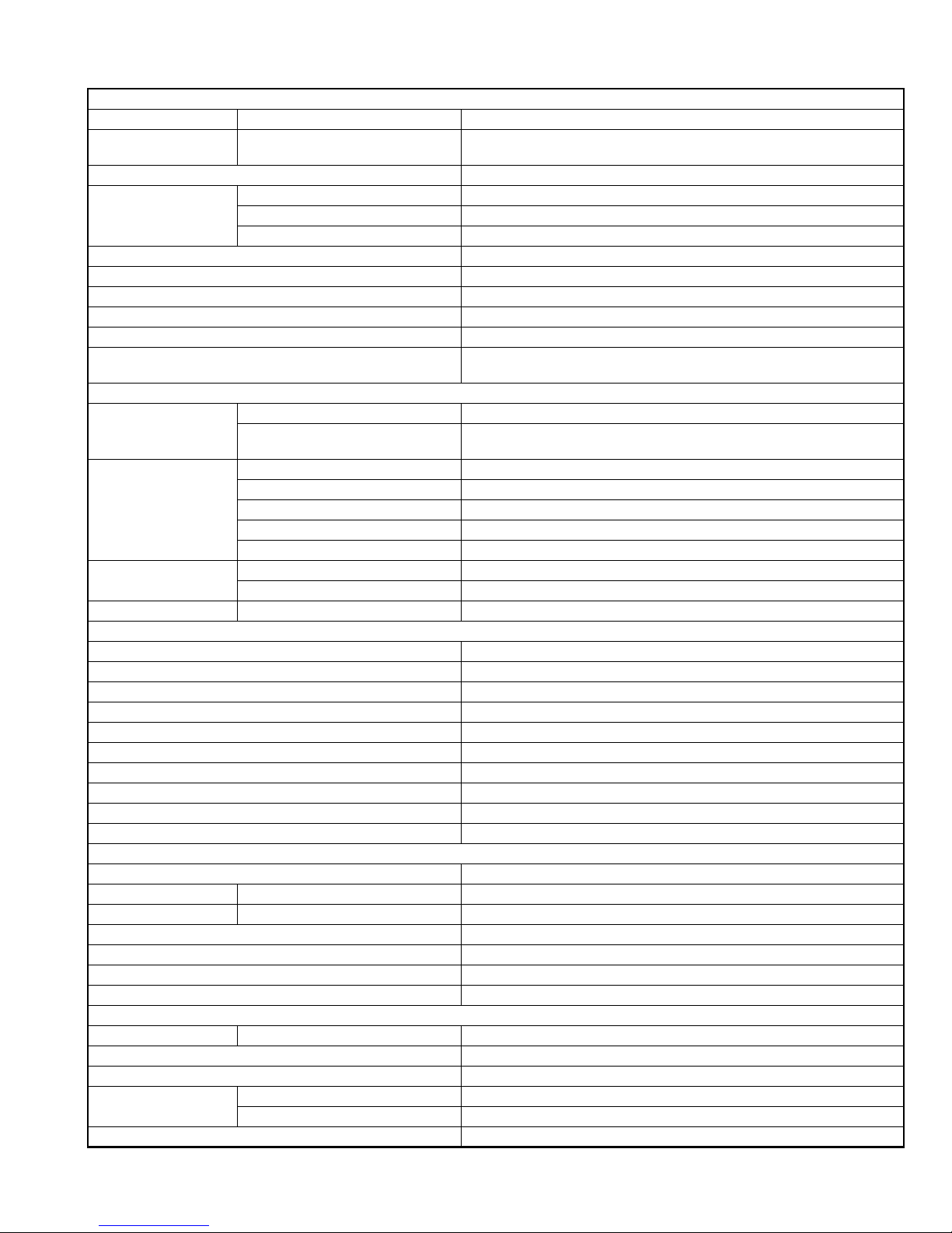
SPECIFICATION
KW-XG700
AUDIO AMPLIFIER SECTION
Power Output 20 W RMS × 4 Channels at 4 Ω and [< or =] 1% THD+N
Signal to Noise Ratio 80 dBA (reference: 1 W into 4 Ω)
Load Impedance 4 Ω (4 Ω to 8 Ω allowance)
Tone Control Range Bass ±12 dB at 60 Hz
Mid-range ±12 dB at 1 kHz
Treble ±12 dB at 10 kHz
Frequency Response 40 Hz to 20 000 Hz
Line-Out Level/Impedance 2.5 V/20 kΩ load (full scale)
Output Impedance 1 kΩ
Subwoofer-Out Level/Impedance 2.5 V/20 kΩ load (full scale)
Other Terminal CD changer, Steering wheel remote input, USB input terminal, Subwoofer input,
Frequency Range FM 87.5 MHz to 107.9 MHz (with channel interval set to 100 kHz or 200 kHz)
AM 530 kHz to 1 710 kHz (with channel interval set to 10 kHz)
FM Tuner Usable Sensitivity 11.3 dBf (1.0 µV/75 Ω)
50 dB Quieting Sensitivity 16.3 dBf (1.8 µV/75 Ω)
Alternate Channel Selectivity (400 kHz) 65 dB
Frequency Response 40 Hz to 15 000 Hz
Stereo Separation 35 dB
AM Tuner Sensitivity 20 µV
Selectivity 35 dB
Type Compact disc player
Signal Detection System Non-contact optical pickup (semiconductor laser)
Number of Channels 2 channels (stereo)
Frequency Response 5 Hz to 20 000 Hz
Dynamic Range 96 dB
Signal-to-Noise Ratio 98 dB
Wow and Flutter Less than measurable limit
MP3 Decoding Format: (MPEG1/2 Audio Layer 3) Max. Bit Rate: 320 kbps
WMA (Windows Media® Audio) Decoding Format Max. Bit Rate: 192 kbps
AAC (Advanced Audio Coding) Decoding Format Max. Bit Rate: 320 kbps
USB Standard USB 1.1
Data Transfer Rate Full Speed Maximum 12 Mbps
Low Speed Maximum 1.5 Mbps
Compatible Device Mass storage class, MTP
Compatible File System FAT 32/16/12
Playable Audio Format MP3/WMA/AAC/WAV
Max. Current Less than 500 mA
Power Requirement Operating Voltage DC 14.4 V (11 V to 16 V allowance)
Grounding System Negative ground
Allowable Operating Temperature 0°C to +40°C (32°F to 104°F)
Dimensions (W × H × D)
(approx.)
Mass 1.8 kg (4.0 lbs) (excluding accessories)
Installation Size 178 mm × 100 mm × 158 mm (7-1/16" × 3-15/16" × 6-1/4")
Set Size 178 mm × 100 mm × 178 mm (7-1/16" × 3-15/16" × 7-1/16")
AUX (auxiliary) input jack
TUNER SECTION
87.5 MHz to 108.0 MHz (with channel interval set to 50 kHz)
531 kHz to 1 602 kHz (with channel interval set to 9 kHz)
CD PLAYER SECTION
USB DEVICE
GENERAL
Design and specifications are subject to change without notice.
1-2 (No.MA346)
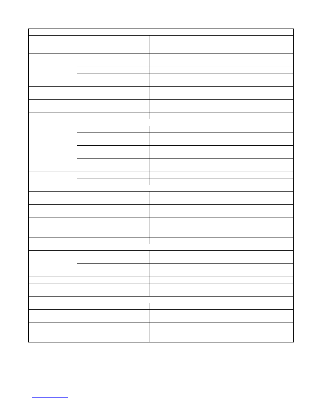
KW-XG701
AUDIO AMPLIFIER SECTION
Maximum Power Output Front and rear 50 W per channel
Continuous Power Output
(RMS)
Load Impedance 4 Ω (4 Ω to 8 Ω allowance)
Tone Control Range Bass ±12 dB at 60 Hz
Frequency Response 40 Hz to 20 000 Hz
Signal to Noise Ratio 70 dB
Line-Out Level/Impedance 2.5 V/20 kΩ load (full scale)
Output Impedance 1 kΩ
Subwoofer-Out Level/Impedance 2.5 V/20 kΩ load (full scale)
Other Terminal CD changer, Steering wheel remote input, USB input terminal, Subwoofer input,
Frequency Range FM 87.5 MHz to 108.0 MHz
FM Tuner Usable Sensitivity 11.3 dBf (1.0 µV/75 Ω)
MW Tuner Sensitivity 20 µV
LW Tuner Sensitivity 50 µV
Type Compact disc player
Signal Detection System Non-contact optical pickup (semiconductor laser)
Number of Channels 2 channels (stereo)
Frequency Response 5 Hz to 20 000 Hz
Dynamic Range 96 dB
Signal-to-Noise Ratio 98 dB
Wow and Flutter Less than measurable limit
MP3 Decoding Format: (MPEG1/2 Audio Layer 3) Max. Bit Rate: 320 kbps
WMA (Windows Media® Audio) Decoding Format Max. Bit Rate: 192 kbps
AAC (Advanced Audio Coding) Decoding Format Max. Bit Rate: 320 kbps
USB Standard USB 1.1
Data Transfer Rate Full Speed Maximum 12 Mbps
Compatible Device Mass storage class, MTP
Compatible File System FAT 32/16/12
Playable Audio Format MP3/WMA/AAC/WAV
Max. Current Less than 500 mA
Power Requirement Operating Voltage DC 14.4 V (11 V to 16 V allowance)
Grounding System Negative ground
Allowable Operating Temperature 0°C to +40°C
Dimensions (W × H × D)
(approx.)
Mass 2.3 kg (excluding accessories)
Front and rear 19 W per channel into 4 Ω, 40 Hz to 20 000 Hz at no more than 0.8% total har-
monic distortion.
Mid-range ±12 dB at 1 kHz
Treble ±12 dB at 10 kHz
AUX (auxiliary) input jack
TUNER SECTION
AM (MW) 522 kHz to 1 620 kHz
(LW) 144 kHz to 279 kHz
50 dB Quieting Sensitivity 16.3 dBf (1.8 µV/75 Ω)
Alternate Channel Selectivity (400 kHz) 65 dB
Frequency Response 40 Hz to 15 000 Hz
Stereo Separation 30 dB
Selectivity 35 dB
CD PLAYER SECTION
USB DEVICE
Low Speed Maximum 1.5 Mbps
GENERAL
Installation Size 182 mm × 111 mm × 158 mm
Set Size 178 mm × 100 mm × 178 mm
Design and specifications are subject to change without notice.
(No.MA346)1-3

KW-XG704
AUDIO AMPLIFIER SECTION
Maximum Power Output Front and rear 50 W per channel
Continuous Power Output
(RMS)
Load Impedance 4 Ω (4 Ω to 8 Ω allowance)
Tone Control Range Bass ±12 dB at 60 Hz
Frequency Response 40 Hz to 20 000 Hz
Signal-to-Noise Ratio 70 dB
Line-Out Level/Impedance 2.5 V/20 kΩ load (full scale)
Output Impedance 1 kΩ
Subwoofer-Out Level/Impedance 2.5 V/20 kΩ load (full scale)
Other Terminal CD changer, USB input terminal, Subwoofer input, AUX (auxiliary) input jack
Frequency Range FM 87.5 MHz to 108.0 MHz
FM Tuner Usable Sensitivity 11.3 dBf (1.0 µV/75 Ω)
AM Tuner Sensitivity 20 µV
Type Compact disc player
Signal Detection System Non-contact optical pickup (semiconductor laser)
Number of Channels 2 channels (stereo)
Frequency Response 5 Hz to 20 000 Hz
Dynamic Range/Signal-to-Noise Ratio 96 dB/98 dB
Wow and Flutter Less than measurable limit
MP3 Decoding Format: (MPEG1/2 Audio Layer 3) Max. Bit Rate: 320 kbps
WMA (Windows Media® Audio) Decoding Format Max. Bit Rate: 192 kbps
USB Standard USB 1.1
Data Transfer Rate Full Speed Maximum 12 Mbps
Compatible Device Mass storage class
Compatible File System FAT 32/16/12
Playable Audio Format MP3/WMA/WAV
Max. Current Less than 500 mA
Power Requirement Operating Voltage DC 14.4 V (11 V to 16 V allowance)
Grounding System Negative ground
Allowable Operating Temperature 0°C to +40°C
Dimensions (W × H × D)
(approx.)
Mass 1.8 kg (excluding accessories)
Front and rear 19 W per channel into 4 Ω, 40 Hz to 20 000 Hz at no more than 0.8% total har-
monic distortion.
Mid-range ±12 dB at 1 kHz
Treble ±12 dB at 10 kHz
TUNER SECTION
AM 531 kHz to 1 602 kHz
50 dB Quieting Sensitivity 16.3 dBf (1.8 µV/75 Ω)
Alternate Channel Selectivity (400 kHz) 65 dB
Frequency Response 40 Hz to 15 000 Hz
Stereo Separation 30 dB
Selectivity 35 dB
CD PLAYER SECTION
USB DEVICE
Low Speed Maximum 1.5 Mbps
GENERAL
Installation Size 178 mm × 100 mm × 158 mm
Set Size: 178 mm × 100 mm × 178 mm
Design and specifications are subject to change without notice.
1-4 (No.MA346)
KW-XG705/KW-XG706/KW-XG708
AUDIO AMPLIFIER SECTION
Maximum Power Output Front and rear 50 W per channel
Continuous Power Output
(RMS)
Load Impedance 4 Ω (4 Ω to 8 Ω allowance)
Tone Control Range Bass ±12 dB at 60 Hz
Frequency Response 40 Hz to 20 000 Hz
Signal-to-Noise Ratio 70 dB
Line-Out Level/Impedance 2.5 V/20 kΩ load (full scale)
Output Impedance 1 kΩ
Subwoofer-Out Level/Impedance 2.5 V/20 kΩ load (full scale)
Other Terminal CD changer, USB input terminal, Subwoofer input, AUX (auxiliary) input jack
Frequency Range FM 87.5 MHz to 108.0 MHz
FM Tuner Usable Sensitivity 11.3 dBf (1.0 µV/75 Ω)
AM Tuner Sensitivity 20 µV
Type Compact disc player
Signal Detection System Non-contact optical pickup (semiconductor laser)
Number of Channels 2 channels (stereo)
Frequency Response 5 Hz to 20 000 Hz
Dynamic Range/Signal-to-Noise Ratio 96 dB/98 dB
Wow and Flutter Less than measurable limit
MP3 Decoding Format: (MPEG1/2 Audio Layer 3) Max. Bit Rate: 320 kbps
WMA (Windows Media® Audio) Decoding Format Max. Bit Rate: 192 kbps
USB Standard USB 1.1
Data Transfer Rate Full Speed Maximum 12 Mbps
Compatible Device Mass storage class
Compatible File System FAT 32/16/12
Playable Audio Format MP3/WMA/WAV
Max. Current Less than 500 mA
Power Requirement Operating Voltage DC 14.4 V (11 V to 16 V allowance)
Grounding System Negative ground
Allowable Operating Temperature 0°C to +40°C
Dimensions (W × H × D)
(approx.)
Mass 1.8 kg (excluding accessories)
Front and rear 19 W per channel into 4 Ω, 40 Hz to 20 000 Hz at no more than 0.8% total har-
monic distortion.
Mid-range ±12 dB at 1 kHz
Treble ±12 dB at 10 kHz
TUNER SECTION
AM 531 kHz to 1 602 kHz
50 dB Quieting Sensitivity 16.3 dBf (1.8 µV/75 Ω)
Alternate Channel Selectivity (400 kHz) 65 dB
Frequency Response 40 Hz to 15 000 Hz
Stereo Separation 30 dB
Selectivity 35 dB
CD PLAYER SECTION
USB DEVICE
Low Speed Maximum 1.5 Mbps
GENERAL
Installation Size 178 mm × 100 mm × 158 mm
Set Size 178 mm × 100 mm × 178 mm
Design and specifications are subject to change without notice.
(No.MA346)1-5

KW-XG707
AUDIO AMPLIFIER SECTION
Maximum Power Output Front and rear 50 W per channel
Continuous Power Output
(RMS)
Load Impedance 4 Ω (4 Ω to 8 Ω allowance)
Tone Control Range Bass ±12 dB at 60 Hz
Frequency Response 40 Hz to 20 000 Hz
Signal to Noise Ratio 70 dB
Line-Out Level/Impedance 2.5 V/20 kΩ load (full scale)
Output Impedance 1 kΩ
Subwoofer-Out Level/Impedance 2.5 V/20 kΩ load (full scale)
Other Terminal CD changer, USB input terminal, Subwoofer input, AUX (auxilliary) input jack
Frequency Range FM1/FM2 87.5 MHz to 108.0 MHz
FM Tuner Usable Sensitivity 11.3 dBf (1.0 µV/75 Ω)
MW Tuner Sensitivity 20 µV
LW Tuner Sensitivity 50 µV
Type
Signal Detection System
Number of Channels 2 channels (stereo)
Frequency Response 5 Hz to 20 000 Hz
Dynamic Range 96 dB
Signal-to-Noise Ratio 98 dB
Wow and Flutter Less than measurable limit
MP3 Decoding Format: (MPEG1/2 Audio Layer 3) Max. Bit Rate: 320 kbps
WMA (Windows Media® Audio) Decoding Format Max. Bit Rate: 192 kbps
AAC (Advanced Audio Coding) Decoding Format Max. Bit Rate: 320 kbps
USB Standard USB 1.1
Data Transfer Rate Full Speed Maximum 12 Mbps
Compatible Device Mass storage class, MTP
Compatible File System FAT 32/16/12
Playable Audio Format MP3/WMA/AAC/WAV
Max. Current: Less than 500 mA
Power Requirement Operating Voltage DC 14.4 V (11 V to 16 V allowance)
Grounding System Negative ground
Allowable Operating Temperature 0°C to +40°C
Dimensions (W × H × D)
(approx.)
Mass 2.3 kg (excluding accessories)
Front and rear 19 W per channel into 4 Ω, 40 Hz to 20 000 Hz at no more than 0.8% total har-
monic distortion.
Mid-range ±12 dB at 1 kHz
Treble ±12 dB at 10 kHz
TUNER SECTION
FM3 65.00 MHz to 74.00 MHz
AM (MW) 522 kHz to 1 620 kHz
(LW) 144 kHz to 279 kHz
50 dB Quieting Sensitivity 16.3 dBf (1.8 µV/75 Ω)
Alternate Channel Selectivity (400 kHz) 65 dB
Frequency Response 40 Hz to 15 000 Hz
Stereo Separation 30 dB
Selectivity 35 dB
CD PLAYER SECTION
Compact disc player
Non-contact optical pickup (semiconductor laser)
USB DEVICE
Low Speed Maximum 1.5 Mbps
GENERAL
Installation Size 182 mm × 111 mm × 158 mm
Set Size 178 mm × 100 mm × 178 mm
Design and specifications are subject to change without notice.
1-6 (No.MA346)
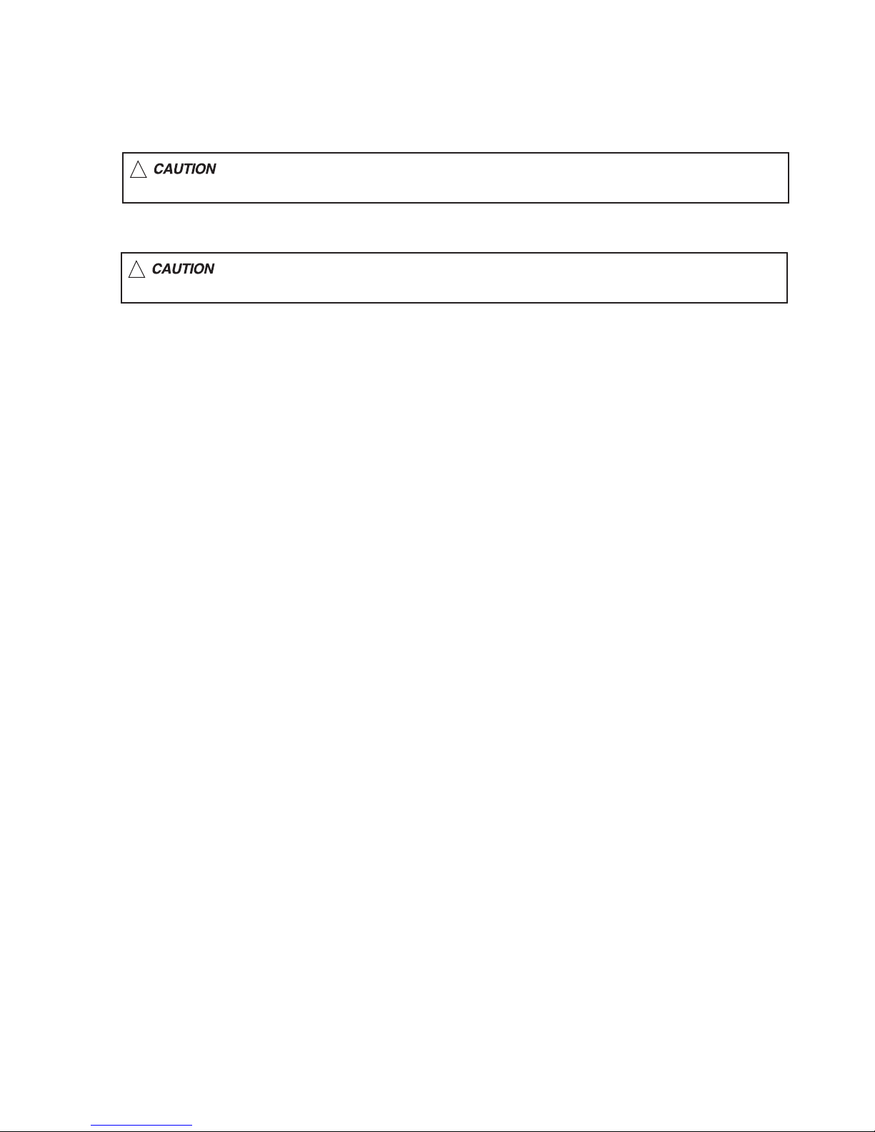
1.1 Safety Precautions
SECTION 1
PRECAUTION
!
!
Burrs formed during molding may be left over on some parts of the chassis. Therefore,
pay attention to such burrs in the case of preforming repair of this system.
Please use enough caution not to see the beam directly or touch it in case of an
adjustment or operation check.
(No.MA346)1-7
1.2 Preventing static electricity
Electrostatic discharge (ESD), which occurs when static electricity stored in the body, fabric, etc. is discharged, can destroy the laser
diode in the traverse unit (optical pickup). Take care to prevent this when performing repairs.
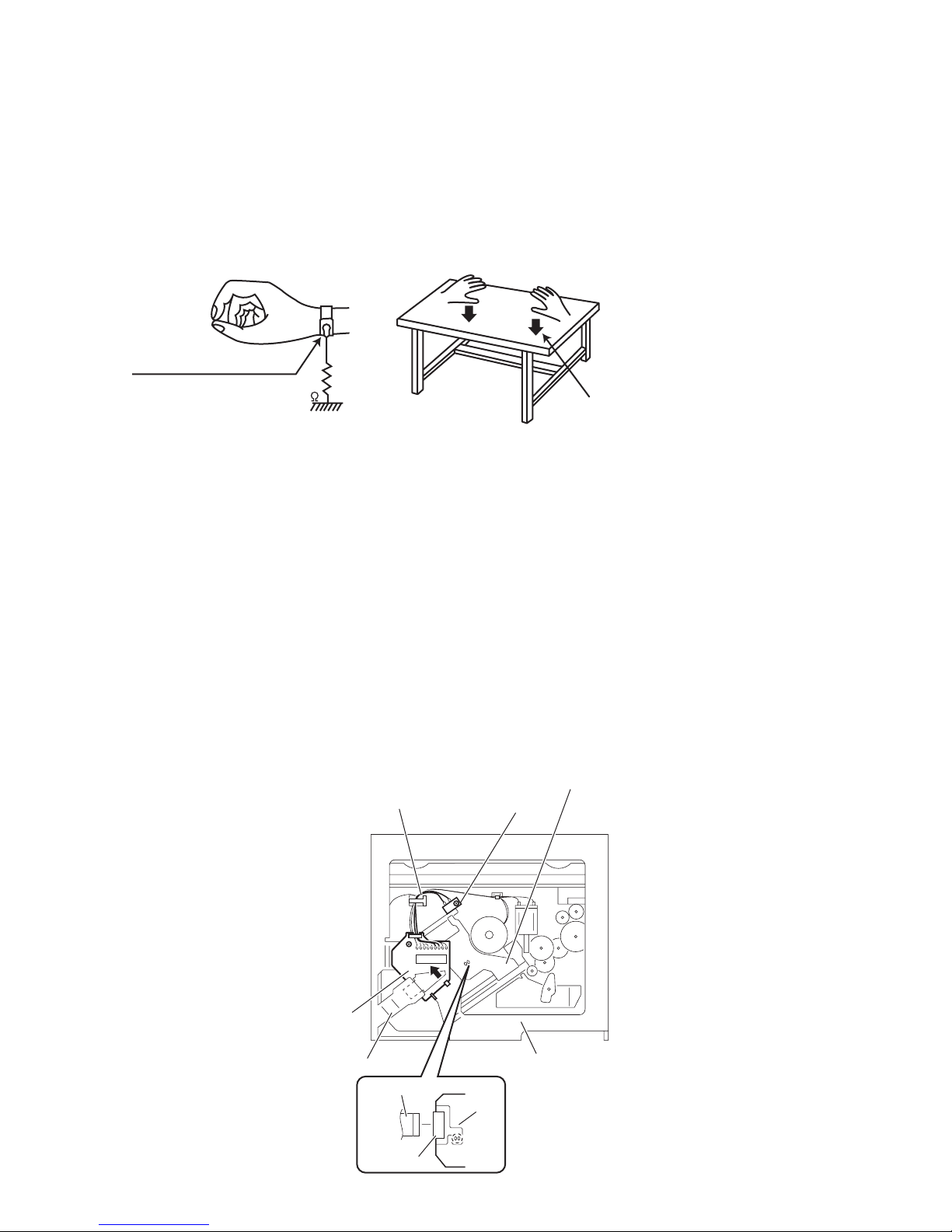
1.2.1 Grounding to prevent damage by static electricity
Static electricity in the work area can destroy the optical pickup (laser diode) in devices such as laser products.
Be careful to use proper grounding in the area where repairs are being performed.
(1) Ground the workbench
Ground the workbench by laying conductive material (such as a conductive sheet) or an iron plate over it before placing the
traverse unit (optical pickup) on it.
(2) Ground yourself
Use an anti-static wrist strap to release any static electricity built up in your body.
(caption)
Anti-static wrist strap
1M
Conductive material
(conductive sheet) or iron plate
(3) Handling the optical pickup
• In order to maintain quality during transport and before installation, both sides of the laser diode on the replacement optical
pickup are shorted. After replacement, return the shorted parts to their original condition.
(Refer to the text.)
• Do not use a tester to check the condition of the laser diode in the optical pickup. The tester's internal power source can easily
destroy the laser diode.
1.3 Handling the traverse unit (optical pickup)
(1) Do not subject the traverse unit (optical pickup) to strong shocks, as it is a sensitive, complex unit.
(2) Cut off the shorted part of the flexible cable using nippers, etc. after replacing the optical pickup. For specific details, refer to the
replacement procedure in the text. Remove the anti-static pin when replacing the traverse unit. Be careful not to take too long a
time when attaching it to the connector.
(3) Handle the flexible cable carefully as it may break when subjected to strong force.
(4) It is not possible to adjust the semi-fixed resistor that adjusts the laser power. Do not turn it.
1.4 Attention when traverse unit is decomposed
*Please refer to "Disassembly method" in the text for the pickup unit.
• Apply solder to the short land before the card wire is disconnected from the connector on the pickup unit.
(If the card wire is disconnected without applying solder, the pickup may be destroyed by static electricity.)
• In the assembly, be sure to remove solder from the short land after connecting the card wire.
Pickup
Wires
Push switch
Base board
1-8 (No.MA346)
Frame
Flexible wire
Connector
CD mechanism
assembly
Pickup
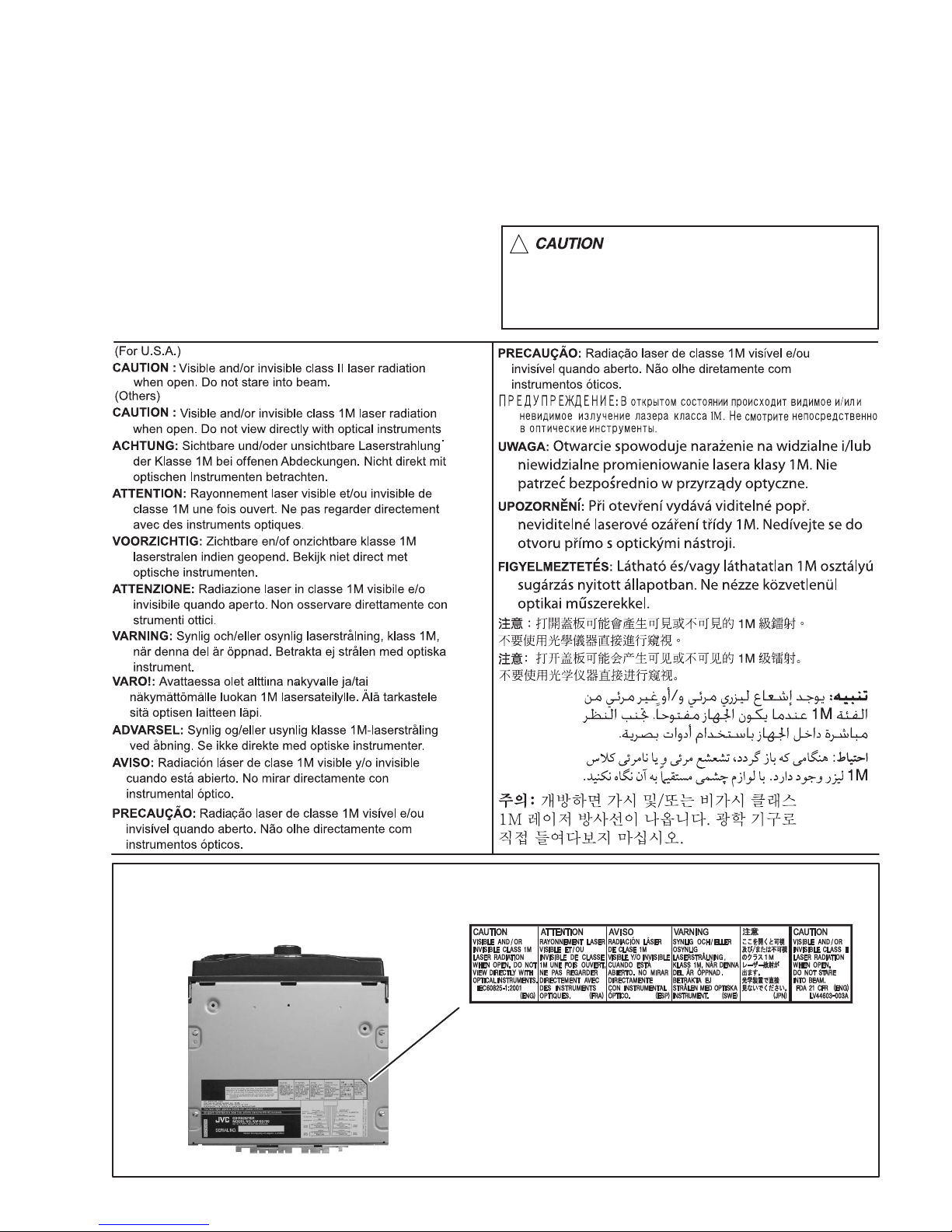
1.5 Important for laser products
1.CLASS 1 LASER PRODUCT
2.CAUTION :
(For U.S.A.) Visible and/or invisible class II laser radiation
when open. Do not stare into beam.
(Others) Visible and/or invisible class 1M laser radiation
when open. Do not view directly with optical instruments.
3.CAUTION : Visible and/or invisible laser radiation when
open and inter lock failed or defeated. Avoid direct
exposure to beam.
4.CAUTION : This laser product uses visible and/or invisible
laser radiation and is equipped with safety switches which
prevent emission of radiation when the drawer is open and
the safety interlocks have failed or are defeated. It is
dangerous to defeat the safety switches.
5.CAUTION : If safety switches malfunction, the laser is able
to function.
6.CAUTION : Use of controls, adjustments or performance of
procedures other than those specified here in may result in
hazardous radiation exposure.
!
Please use enough caution not to
see the beam directly or touch it
in case of an adjustment or operation
check.
REPRODUCTION AND POSITION OF LABELS and PRINT
WARNING LABEL and PRINT
(No.MA346)1-9

SECTION 2
SPECIFIC SERVICE INSTRUCTIONS
This service manual does not describe SPECIFIC SERVICE INSTRUCTIONS.
1-10 (No.MA346)
SECTION 3
DISASSEMBLY
3.1 Main body
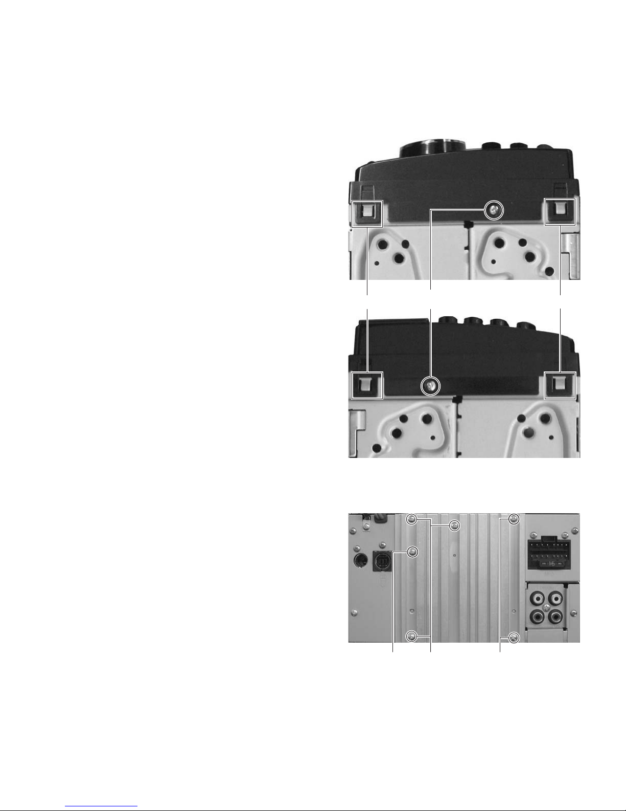
3.1.1 Removing the FRONT PANEL assembly
(See Fig.1)
(1) From the bottom side of main body, remove the two screws
A attaching the both side of the FRONT PANEL assembly.
(2) Disengage two hooks a engaged CHASSIS assembly.
3.1.2 Removing the HEAT SINK
(See Fig.2)
(1) Remove the five screws B and one screw C attaching the
HEAT SINK.
hook a hook a
A
Fig.1
BBC
Fig.2
(No.MA346)1-11
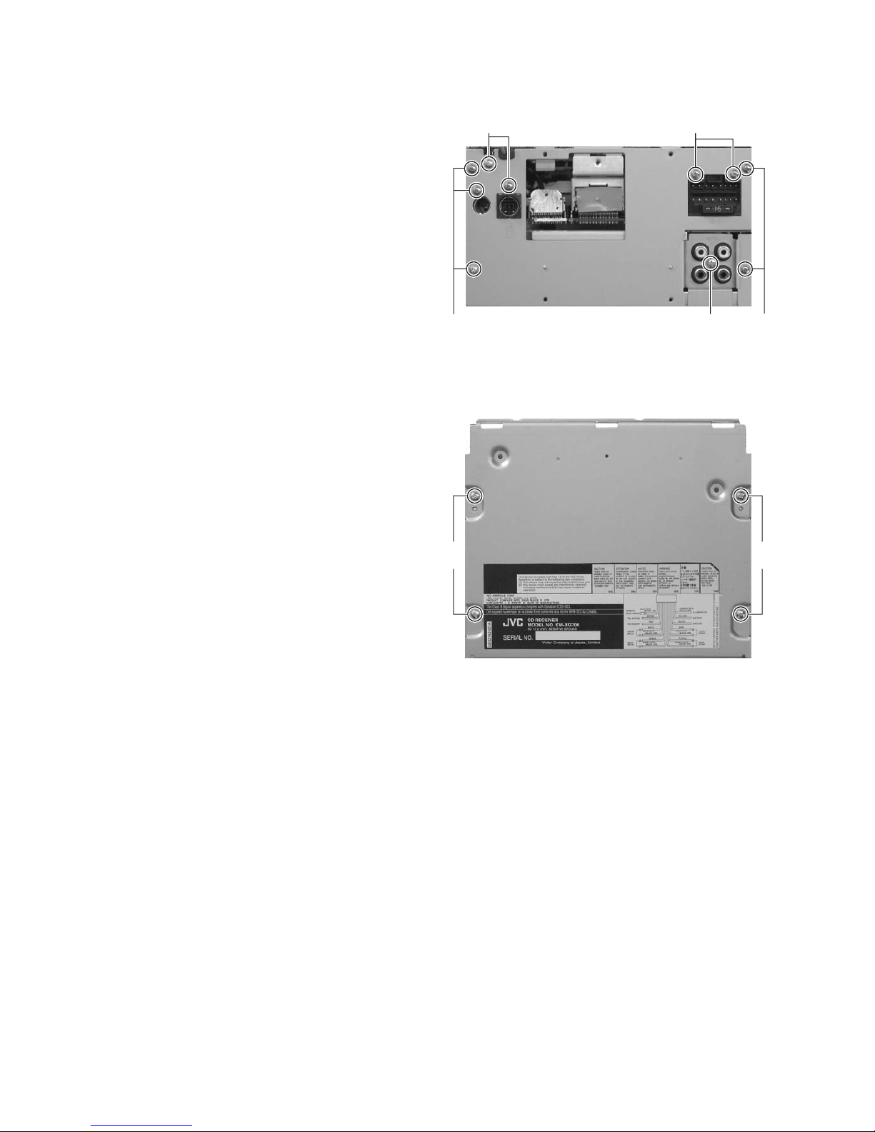
3.1.3 Removing the REAR BRACKET
(See Fig.3)
(1) Remove the seven screws D, two screws E and one screw
F attaching the REAR BRACKET.
D
E
3.1.4 Removing the BOTTOM CHASSIS assembly
(See Fig.4)
(1) Remove the four screws G attaching the BOTTOM CHAS-
SIS assembly.
DD
Fig.3
F
GG
Fig.4
1-12 (No.MA346)
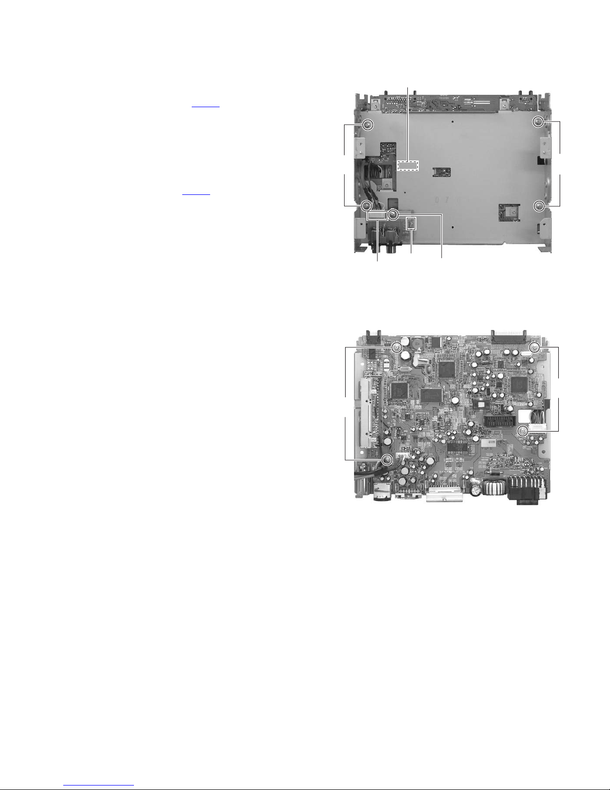
3.1.5 Removing the FUNC BOARD assembly
(See Fig.5)
(1) Remove the one screw H attaching the FUNC BOARD as-
sembly.
(2) Disconnect the connecter wire from MAIN BOARD assem-
bly connected to connector CN322
assembly.
(3) Straighten hook b attaching the FUNC BOARD assembly.
3.1.6 Removing the MIDDLE CHASSIS
(See Fig.5)
(1) Remove the four screws J attaching the MIDDLE CHAS-
SIS.
(2) Disconnect the connector CN501
MIDDLE CHASSIS from the CD mechanism assembly in
an upward direction.
3.1.7 Removing the MAIN BOARD assembly
(See Fig.6)
(1) Remove the four screws K attaching the MAIN BOARD as-
sembly.
of the FUNC BOARD
of the main board on the
CN322
CN501
hook
JJ
b
H
Fig.5
K
K
Fig.6
(No.MA346)1-13
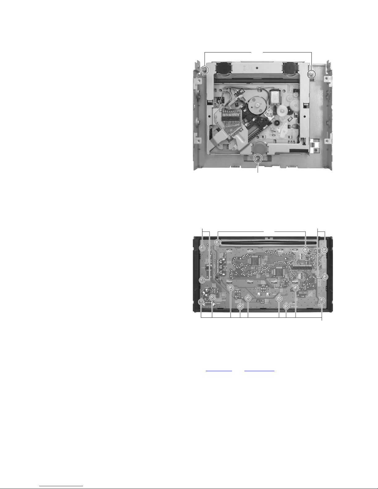
3.1.8 Removing the CD MECHANISM assembly
(See Fig.7)
(1) Remove the three screws L attaching the CD MECHA-
NISM assembly.
3.1.9 Removing the SWITCH BOARD assembly
(See Fig.8)
(1) Remove the volume knob from the front side of the FRONT
PANEL assembly.
(2) Remove the thirteen screws M and two screws N attaching
the SWITCH BOARD assembly.
L
L
Fig.7
MM
N
3.2 CD mechanism assembly
For CD mechanism, please refer the MECHANISM MANUAL TN2007-1010 (No.MY005
1-14 (No.MA346)
M
Fig.8
and No.MY005B).
SECTION 4
ADJUSTMENT
4.1 Adjustment method
4.1.1 Test instruments required for adjustment
(1) Digital oscilloscope (100MHz)
(2) Electric voltmeter
(3) Digital tester
(4) Tracking offset meter
(5) Test Disc JVC :CTS-1000
(6) Extension cable for check
EXTSH002-22P × 1
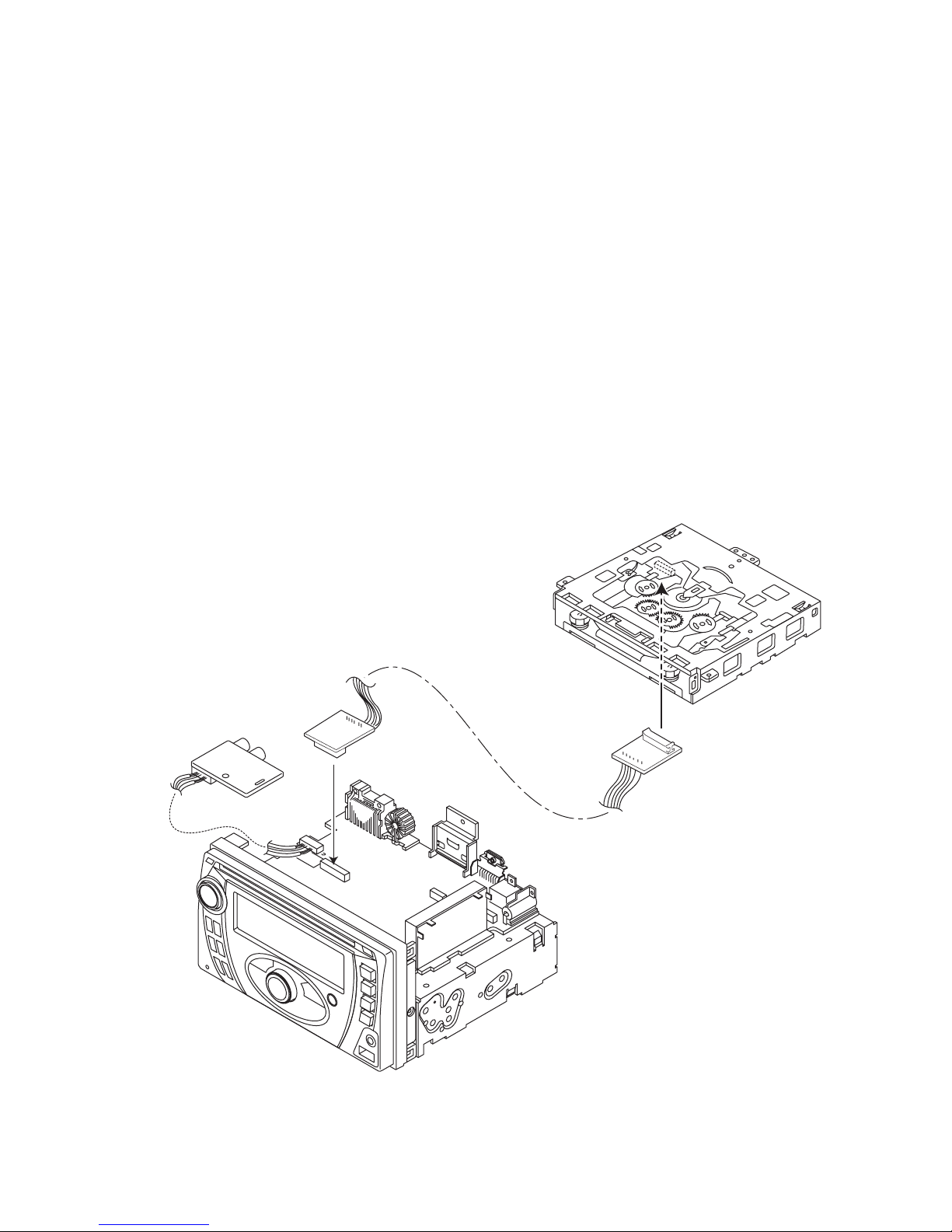
4.1.5 How to connect the extension cable for adjusting
Caution:
Be sure to attach the heat sink and rear bracket onto the power amplifier IC and regulator IC respectively, before supply the power.
If voltage is applied without attaching these parts, the power amplifier IC and regulator IC will be destroyed by heat.
4.1.2 Standard measuring conditions
Power supply voltage : DC14.4V(11 to 16V)
Load impedance : 20K.(2 Speakers connection)
Output Level : Line out 2.5V (Vol. MAX)
4.1.3 Standard volume position
Balance and Bass &Treble volume : lndication"0"
Loudness : OFF
4.1.4 Dummy load
Exclusive dummy load should be used for AM,and FM. For FM
dummy load,there is a loss of 6dB between SSG output and antenna input.The loss of 6dB need not be considered since direct
reading of figures are applied in this working standard.
Extension cable
EXTSH002-22P
(No.MA346)1-15
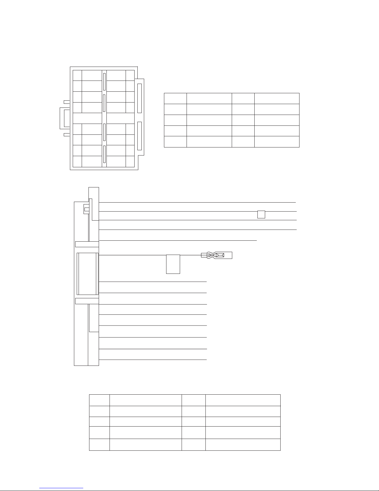
5.1 16 PIN CORD DIAGRAM (for KW-XG700)
SECTION 5
TROUBLESHOOTING
8
7
6
BL/WH
5
4
3
2
1
BK
RD
NC
YL
OR/WH
NC
BR
WH
GN
VI
GY
WH/BK
GN/BK
VI/BK
GY/BK
16 YL
8 BK
7 RD
15 OR/WH
13 BR TEL
5 BL/WH
3 GN
16
15
14
13
12
11
10
9
MEMORY
GND
ACC
ILL
REMOTE
RL+
BK
RD
BL
WH
BR
CAUTION!
REMOTE
ONLY
OUTPUT
Black
Red
Blue
White
Brown
GN
VI
GY
YL
OR
Green
Violet
Gray
Yellow
Orange
GND
11 GN/BK
10 VI/BK
12 WH/BK
RR
FR
FL
RL
TEL
2 VI
4 WH
1 GY
9 GY/BK
Rear Right
Front Right
Front Left
Rear Left
Telephone muting
RL-
RR+
RR-
FL+
FL-
FR+
FR-
REMOTE
ACC
MEMORY
GND
ILL
Remote out
ACC Line
Memory Backup Battery +
Ground
Illuminations Control
1-16 (No.MA346)
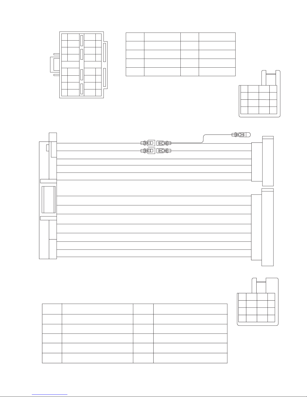
5.2 16 PIN CORD DIAGRAM (for KW-XG701, KW-XG707)
8
7
6
BL/WH
5
4
3
2
1
7 RD
16 YL
15 OR/WH
8 BK
6 BL/WH
13 BR
BK
RD
NC
WH
GN
VI
GY
YL
OR/WH
NC
BR
WH/BK
GN/BK
VI/BK
GY/BK
16
15
14
13
12
11
10
9
ACC
MEMORY
ILL
GND
REMOTE
TEL
BK
RD
BL
WH
BR
Black
Red
Blue
White
Brown
GN
VI
GY
YL
OR
Green
Violet
Gray
Yellow
Orange
RD
1
3
5
7
RD 7
YL 4
BL/WH
6
8
5
2
NC
NC
RD
BR
YL
OR/WH
BK
2
4
6
8
RR
FR
FL
3 GN
11 GN/BK
2 VI
10 VI/BK
4 WH
12 WH/BK
1 GY
9 GY/BK
Rear Right
Front Right
Front Left
RL+
RL-
RR+
RR-
FL+
FL-
FR+
FR-
ANT
ACC
TEL
Auto Antenna
ACC Line
Telephone Muting
7
8
1
2
5
6
3
4
VI/BK
GY/BK
WH/BK
GN/BK
2
4
6
8
VI
1
3
GY
5
WH
GN
7
RL
REMOTE
ILL
Rear Left
Remote
Illuminations Control
GND
MEMORY
Ground
Memory Backup Battery+
(No.MA346)1-17
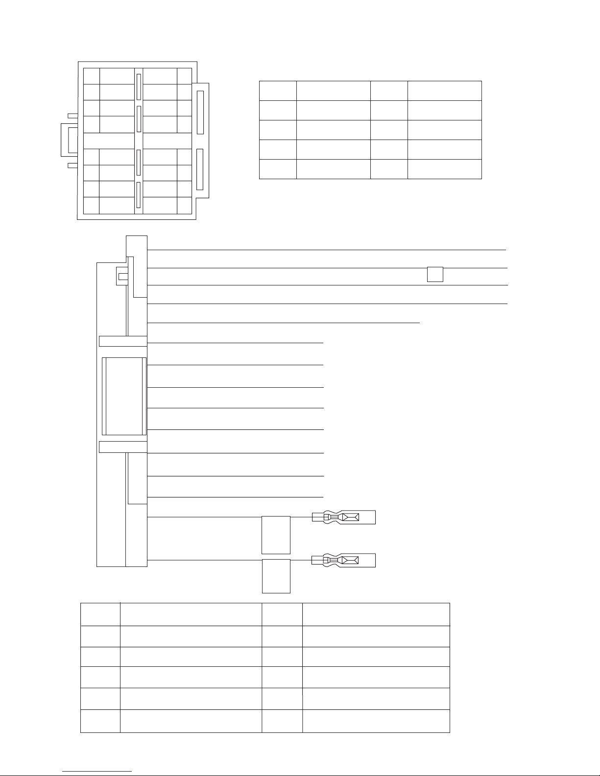
5.3 16 PIN CORD DIAGRAM (for KW-XG-704, KW-XG705, KW-XG706)
8
7
6
5
4
3
2
1
BK
RD
BL
BL/WH
WH
GN
VI
GY
YL
16
OR/WH
WH/BK
GN/BK
VI/BK
GY/BK
15
NC
14
BR
13
12
11
10
16 YL
8 BK
7 RD
15 OR/WH
13 BR
3 GN
11 GN/BK
BK
RD
BL
Black
Red
Blue
WH White
BR
9
MEMORY
GND
ACC
ILL
TEL
RL+
RL-
Brown
GN
Green
VI Violet
GY
YL
Gray
Yellow
OR Orange
GND
RR
FR
FL
2 VI
10 VI/BK
4 WH
12 WH/BK
1 GY
9 GY/BK
5 BL/WH
6 BL
Rear Right
Front Right
Front Left
RR+
RR-
FL+
FL-
FR+
FR-
REMOTE
ANT
REMOTE
CAUTION!
POWER
ANT
ACC
ILL
OUTPUT ONLY
ANTENNA
Auto Antenna
ACC Line
Illuminations Control
RL
REMOTE
TEL
1-18 (No.MA346)
Rear Left
Remote out
Telephone muting
GND
MEMORY
Ground
Memory Backup Battery+
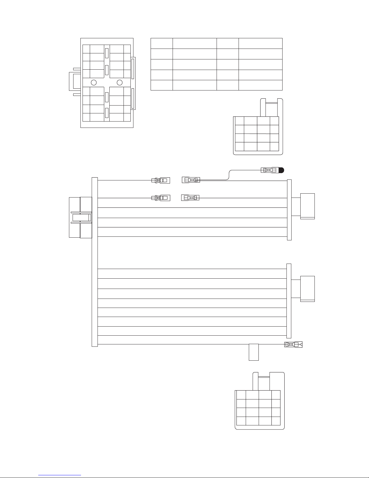
5.4 16 PIN CORD DIAGRAM (for KW-XG708)
8
7
6
5
4
3
2
1
BK
RD1
BL
BL/WH
WH
GN
VI
GY
7
YL1
16
8
6
OR/WH
15
13
RD1
BK
BL
BR
YL1
OR/WH
NC
BR
WH/BK
GN/BK
VI/BK
GY/BK
16
15
14
13
12
11
10
BK
RD
BL
WH
BR
9
Black
Red
Blue
White
Brown
RD3
GN
VI
GY
YL
OR
Green
Gray
1
3
5
7
Violet
Yellow
Orange
NC
OR/WH
BL
RD2
BRNC
YL2
BK
2
4
6
8
RD2
7
YL 2
4
8
5
6
2
3
11
2
10
4
12
1
9
5
GN
GN/BK
VI
VI/BK
WH
WH/BK
GY
GY/BK
BL/WH
7
8
1
2
5
6
3
4
VI/BK
GY/BK
WH/BK
GN/BK
2
4
6
8
VI
1
3
GY
5
WH
GN
7
(No.MA346)1-19
 Loading...