

Page 1
49783200303
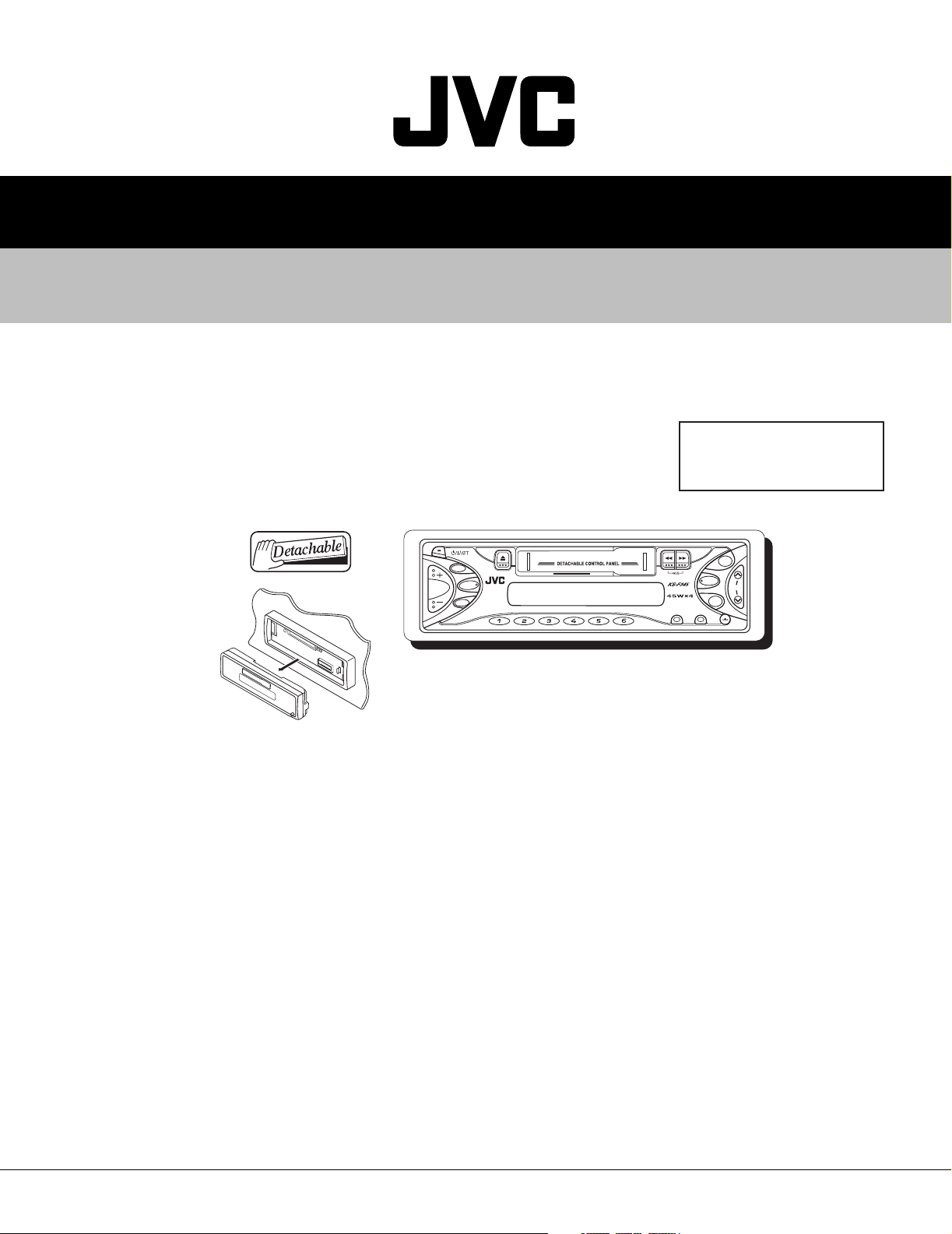
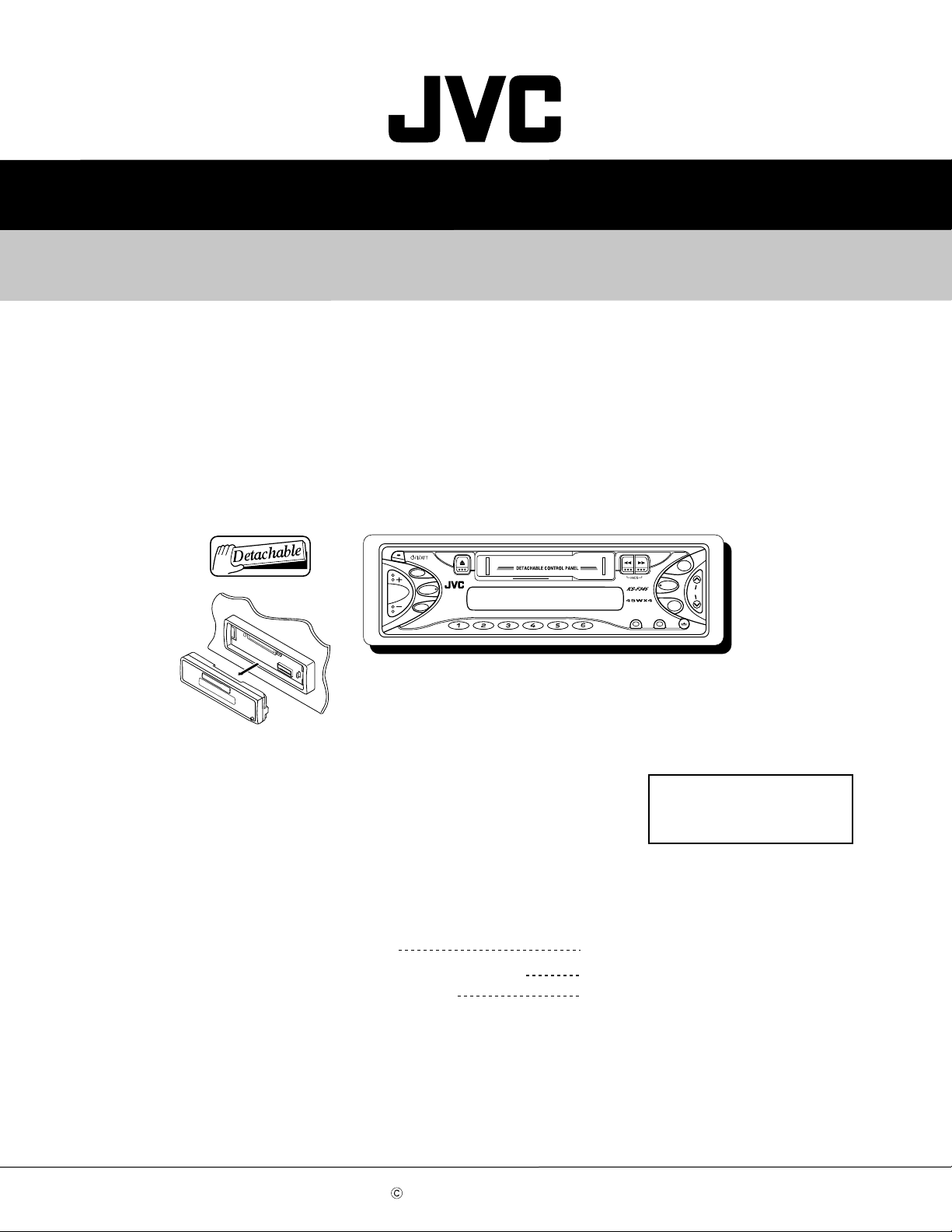
KS-F345
SERVICE MANUAL
CASSETTE RECEIVER
KS-F345
Area Suffix
EE ---- Russian Federation
S.BASS
SEL
D
ISP
FM
A
M
SSM
EX
SCMMO
TABLE OF CONTENTS
1 Important Safety Precautions . . . . . . . . . . . . . . . . . . . . . . . . . . . . . . . . . . . . . . . . . . . . . . . . . . . . . . . . . . . 1-2
2 Disassembly method . . . . . . . . . . . . . . . . . . . . . . . . . . . . . . . . . . . . . . . . . . . . . . . . . . . . . . . . . . . . . . . . . . 1-3
3 Adjustment method. . . . . . . . . . . . . . . . . . . . . . . . . . . . . . . . . . . . . . . . . . . . . . . . . . . . . . . . . . . . . . . . . . . 1-12
4 Description of major ICs. . . . . . . . . . . . . . . . . . . . . . . . . . . . . . . . . . . . . . . . . . . . . . . . . . . . . . . . . . . . . . . 1-16
COPYRIGHT © 2003 VICTOR COMPANY OF JAPAN, LTD.
No.49783
2003/03
Page 2

KS-F345
1.1 Safety Precautions
SECTION 1
Important Safety Precautions
!
Burrs formed during molding may be left over on some parts of the chassis. Therefore,
pay attention to such burrs in the case of preforming repair of this system.
1-2 (No.49783)
Page 3
SECTION 2
Disassembly method
2.1 Main body
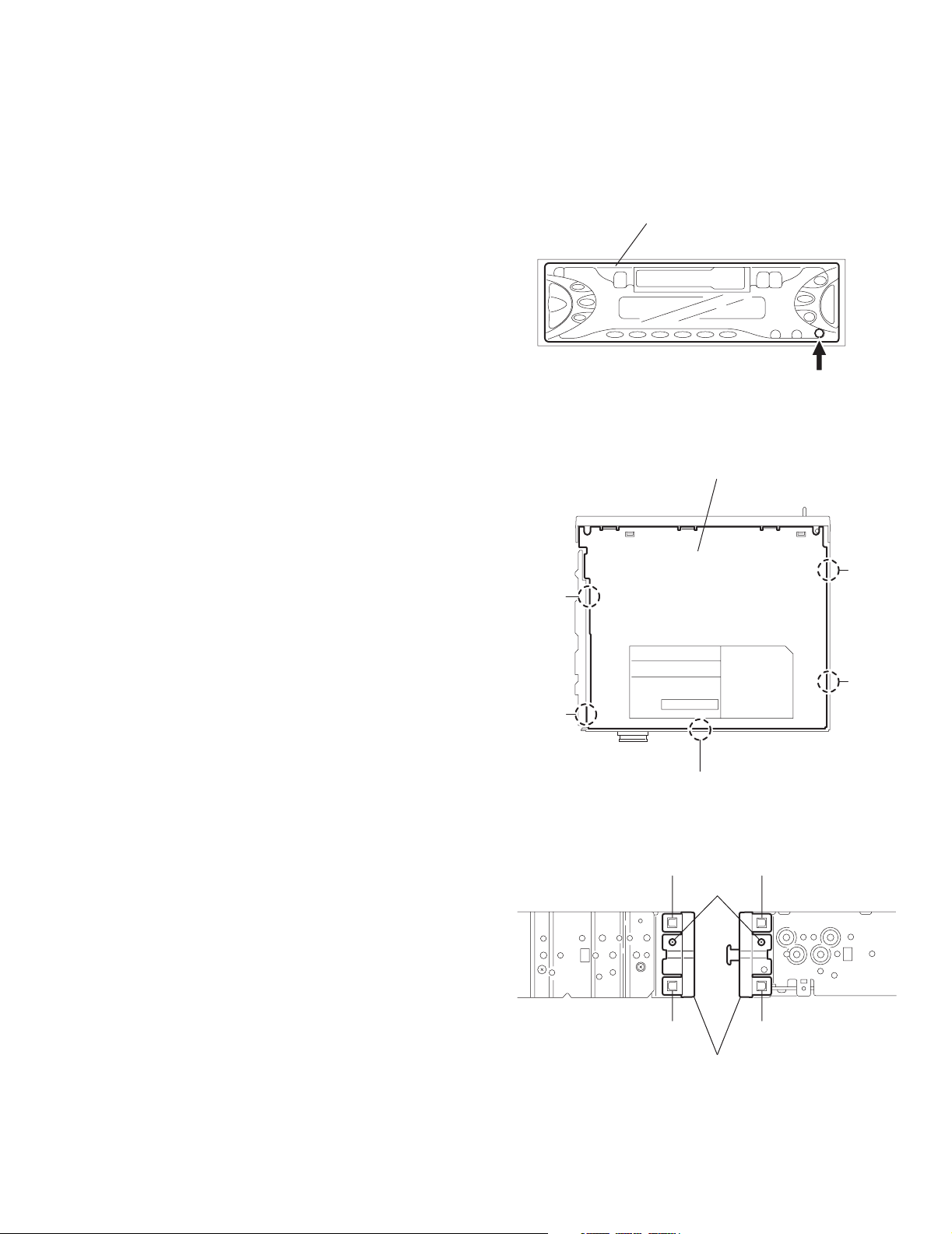
2.1.1 Removing the front panel assembly
(See Fig.1)
(1) Press the release button and remove the front panel as-
sembly.
2.1.2 Removing the bottom cover
(See Fig.2)
• Prior to performing the following procedure, remove the front
panel assembly.
(1) Turn the body upside down.
(2) Insert a screwdriver under the joints to release the two
joints a on the left side, the two joints b on the right side and
the joint c on the back of the body, then remove the bottom
cover from the body.
CAUTION:
When releasing the joint c using a screwdriver, do not
damage the main board.
KS-F345
Front panel assembly
Release button
Fig.1
Bottom cover
Joint b
Joint a
2.1.3 Removing the front chassis
(See Fig.3)
• Prior to performing the following procedure, remove the front
panel assembly and bottom cover.
(1) Remove the screw A on each side of the body.
(2) Release the two joints d and two joints e on the sides, then
remove the front chassis toward the front.
Joint a
Joint c
Fig.2
Joint d Joint e
A
Joint d
Front chassis
Fig.3
Joint e
Joint b
(No.49783)1-3
Page 4
KS-F345
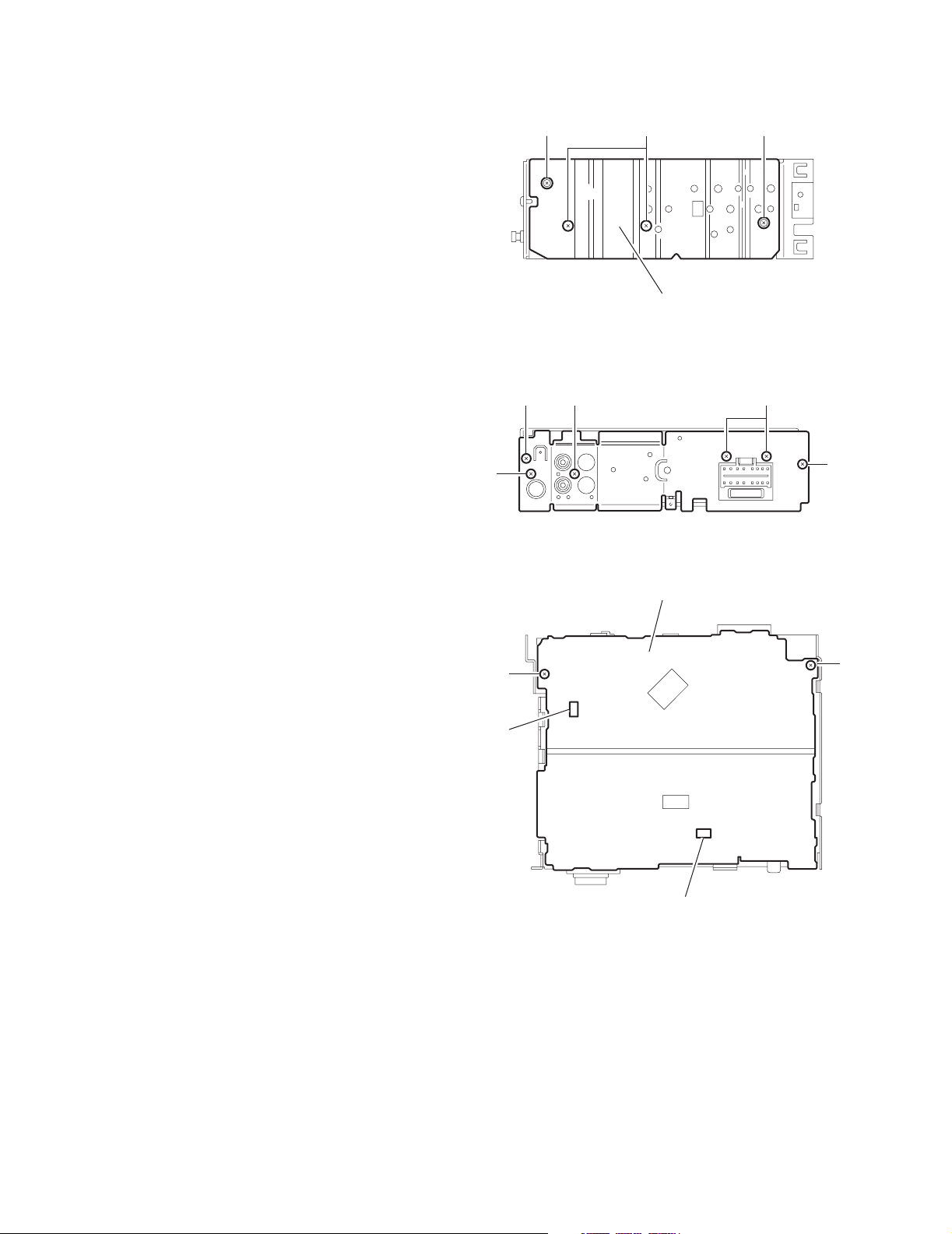
2.1.4 Removing the heat sink
(See Fig.4)
• Prior to performing the following procedure, remove the front
panel assembly.
(1) Remove the two screws B and two screws C attaching the
heat sink on the left side of the body, and remove the heat
sink.
2.1.5 Removing the rear panel
(See Fig.5 )
• Prior to performing the following procedure, remove the front
panel assembly and bottom cover.
(1) Remove the two screws D, one screw E and three screws
F attaching the rear panel on the back of the body.
CB C
Heat sink
Fig.4
D
FF
2.1.6 Removing the main board
(See Fig.6)
• Prior to performing the following procedure, remove the front
panel assembly, bottom cover, front chassis, heat sink and
rear panel.
(1) Remove the two screws G attaching the main board on the
top chassis.
(2) Disconnect the two connectors CN901 and CN721 on the
main board from the cassette mechanism assembly.
E
G
CN721
D
Fig.5
Main board
G
CN901
Fig.6
1-4 (No.49783)
Page 5
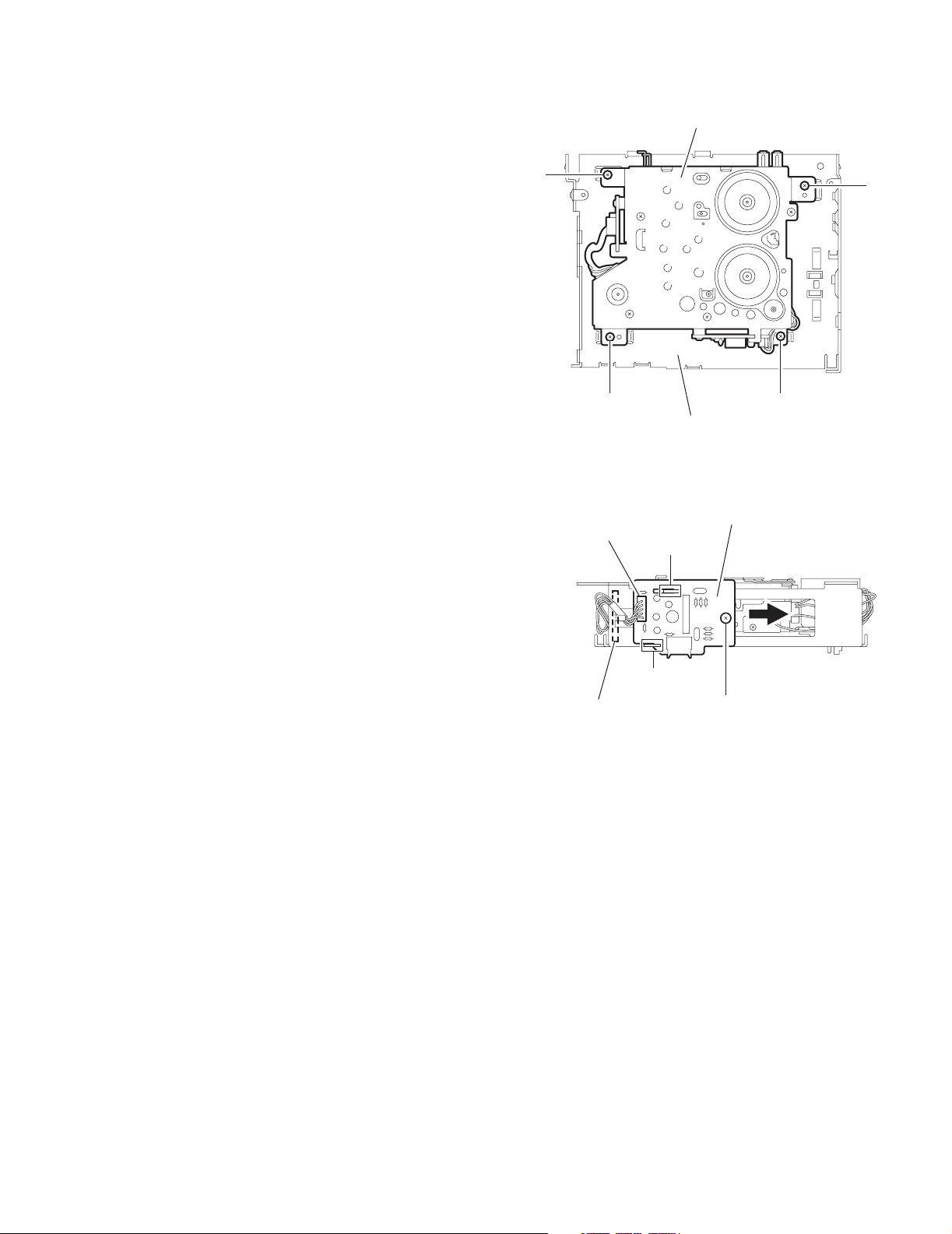
2.1.7 Removing the cassette mechanism assembly
(See Fig.7)
• Prior to performing the following procedure, remove the front
panel assembly, bottom cover, front chassis, heat sink, rear
panel and main board.
(1) Remove the four screws H attaching the cassette mecha-
nism assembly from the top chassis.
H
KS-F345
Cassette mechanism assembly
H
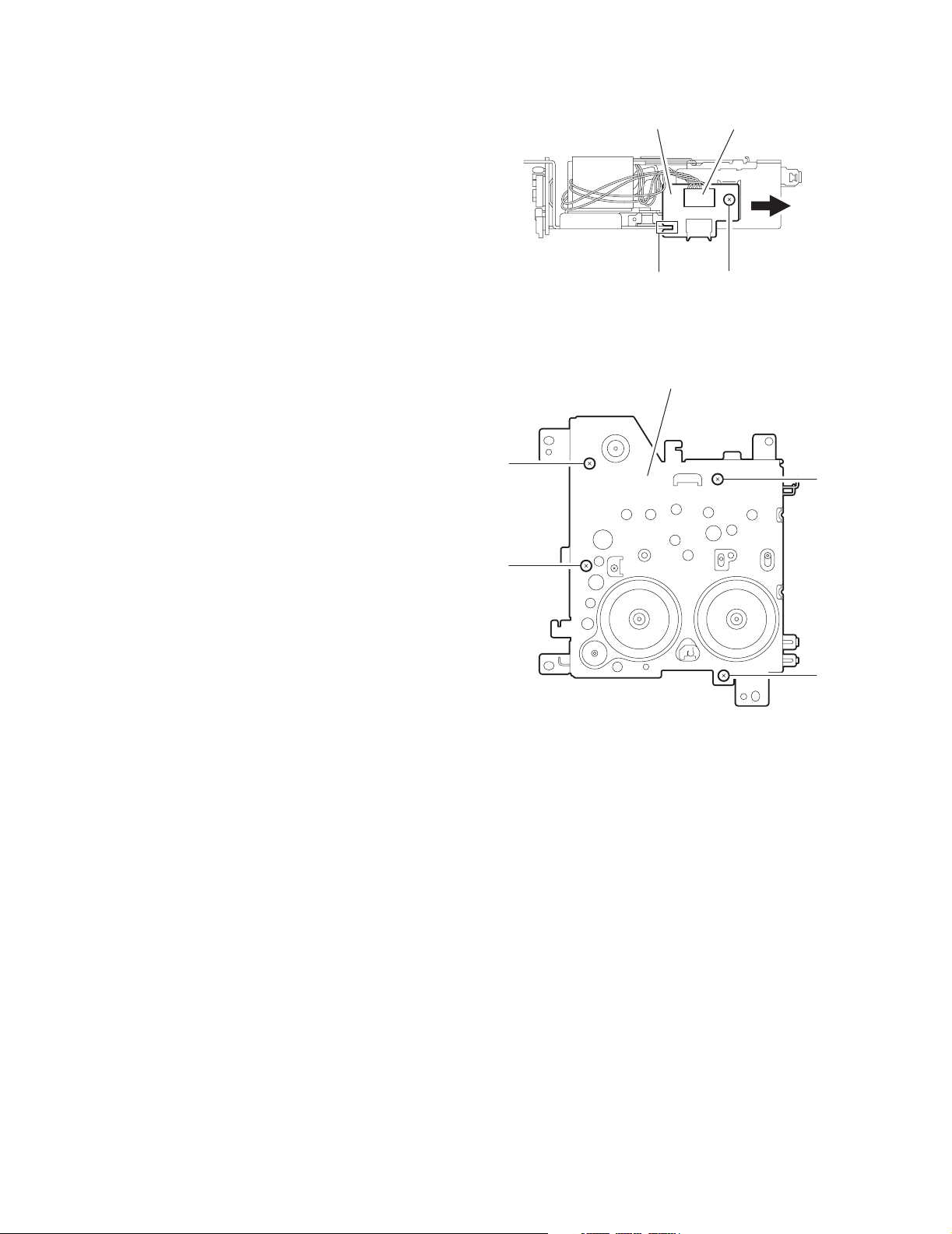
2.1.8 Removing the head amplifier board
(See Fig.8)
• Prior to performing the following procedure, remove the front
panel assembly, bottom cover, front chassis, heat sink, rear
panel, main board and cassette mechanism assembly.
(1) Disconnect the wire from CJ901 on the head amplifier
board.
(2) Remove the one screw J attaching the head amplifier
board.
(3) Move the head amplifier board in the direction of the arrow
to release the two joints f, the head amplifier board can be
removed.
H
CJ901
joint f
To head relay board
H
Top chassis
Fig.7
Head amplifier board
joint f
J
Fig.8
(No.49783)1-5
Page 6
KS-F345
2.1.9 Removing the relay board
(See Fig.9)
• Prior to performing the following procedure, remove the front
panel assembly, bottom cover, front chassis, heat sink, rear
panel, main board and cassette mechanism assembly.
(1) Disconnect the wire from CP722 on the relay board.
(2) Remove the one screw K attaching the relay board.
(3) Move the relay board in the direction of the arrow to release
the joint g, the relay board can be removed.
Relay board
CP722
2.1.10 Removing the mecha bracket
(See Fig.10)
• Prior to performing the following procedure, remove the front
panel assembly, bottom cover, front chassis, heat sink, rear
panel, main board, cassette mechanism assembly, head amplifier board and relay board.
(1) Remove the four screws L attaching the mecha bracket.
joint g
Fig.9
Mecha bracket
K
L
L
L
L
Fig.10
1-6 (No.49783)
Page 7
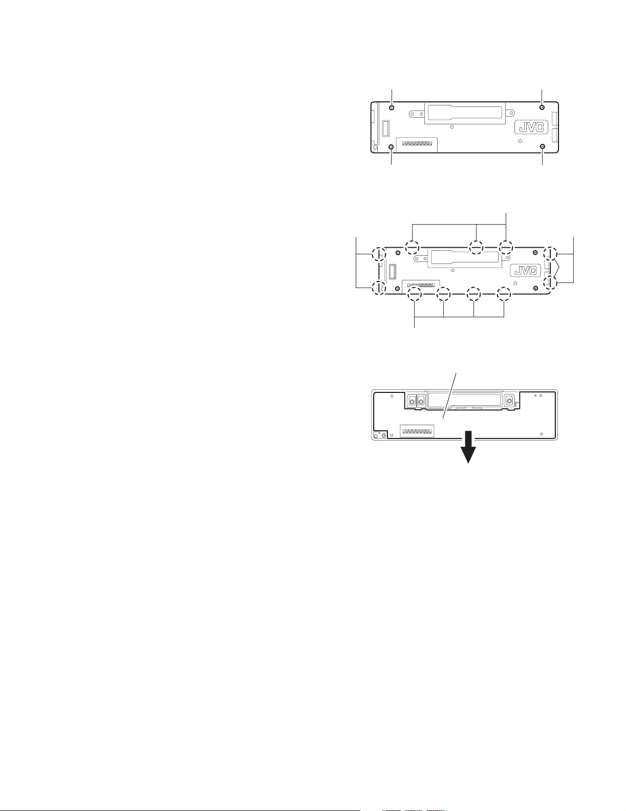
2.1.11 Removing the switch (LCD & key) board
(See Fig.11~13)
• Prior to performing the following procedure, remove the front
panel assembly.
(1) Remove the four screws M attaching the rear cover on the
back of the front panel assembly.
(2) Release the eleven joints h, the front panel and the rear
cover become separate.
(3) Remove the switch board from the rear cover.
M
M
M M
Fig.11
Joint h
KS-F345
Joint h
Joint h
Joint h
Fig.12
Switch (LCD & Key) board
Fig.13
(No.49783)1-7
Page 8
KS-F345
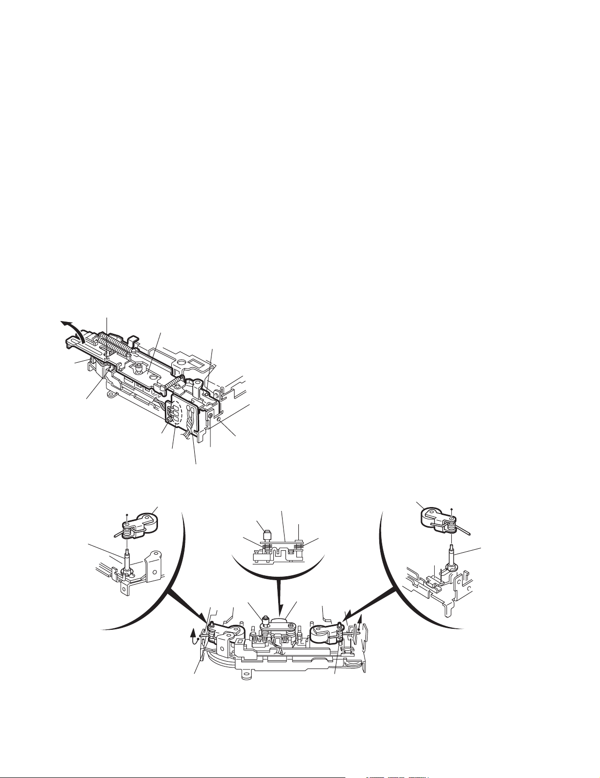
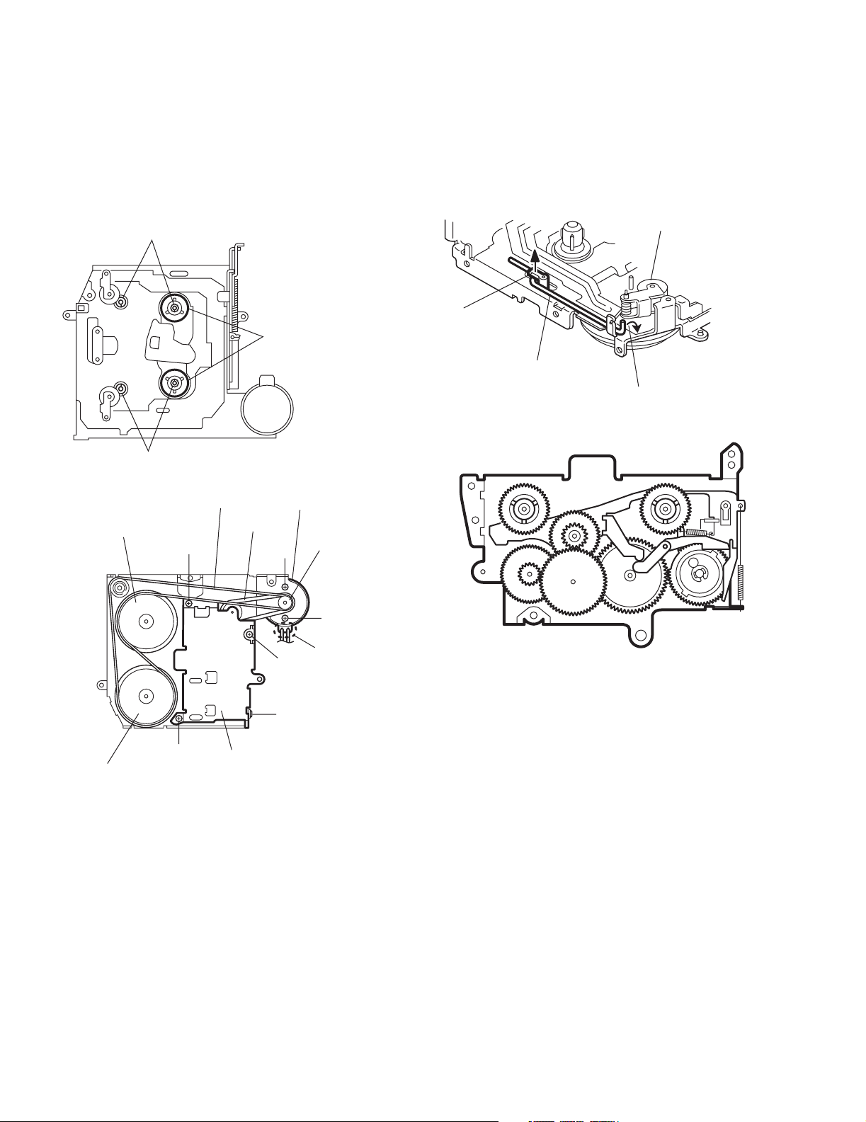
2.2 Cassette mechanism assembly
• Prior to performing the following procedures, remove the head
amplifier board, the relay board and the mechanism bracket.
2.2.1 Removing the direction switch board
(See Fig.1)
(1) Unsolder the three wires a on the direction switch board.
(2) Remove the one screw A attaching the direction switch
board.
2.2.2 Removing the FF / REW lever assembly
(See Fig.1)
(1) Remove the screw B attaching the FF / REW lever assem-
bly on the back of the cassette mechanism assembly.
(2) Remove the screw C on the upper side of the FF / REW
lever assembly.
(3) Lift and pull forward the FF / REW lever assembly to disen-
gage the joints b, c, d and e.
2.2.3 Reattaching the FF / REW lever assembly
(See Fig.1)
(1) Reattach the FF / REW lever assembly to the joint c on the
back of the chassis.
(2) Reattach the pinch-roller shaft e, the change lever d and
the return link e to the chassis.
C
FF / REW lever assembly
Joint c
2.2.4 Removing the playback head
(See Fig.2)
• Prior to performing the following procedure, remove the direc-
tion switch board and the FF / REW lever assembly.
(1) Remove the screw D attaching the playback head.
(2) Remove the C washer and pull out the FF roller.
(3) Remove the S support plate, the A arm spring (a) and (b),
the playback head.
ATTENTION:
The A arm spring (a) differs from the A arm spring (b).
2.2.5 Removing the pinch-roller (R) and (F) assembly
(See Fig.2)
• Prior to performing the following procedure, remove the direc-
tion switch board and the FF / REW lever assembly.
(1) Remove the P arm spring (f) in the pinch-roller (F) assem-
bly from the chassis.
(2) Remove the P arm spring (r) in the pinch-roller (R) assem-
bly from the chassis.
(3) Draw out the pinch roller (F) and (R) assembly from the
shaft.
ATTENTION:
The P arm spring (f) differs from the P arm spring (r).
ATTENTION:
The pinch roller (F) assembly differs from the pinch roller (R)
assembly.
Joint e
Joint d
A
Soldering a
Direction switch board
Fig.1
Pinch-roller (R) assembly
Shaft
Remove the P arm spring (r)
from the chassis.
Joint b
B
C washer
A arm spring (b)
FF roller
S support plate
D
Playback head
Pinch-roller (F) assembly
A arm spring (a)
Shaft
Remove the P arm spring (f)
from the chassis.
1-8 (No.49783)
P arm spring (r)
P arm spring (f)
Fig.2
Page 9
KS-F345
2.2.6 Removing the cassette hanger / cassette holder
(See Fig.3)
• Prior to performing the following procedure, remove the FF /
REW lever assembly.
(1) From the rear of the unit, bend the two tabs f outwards and
disengage the two joints g in the direction of the arrow.
(2) Push the eject lever and remove the cassette holder from
the playback head. Disengage the two joints h of the cassette hanger / cassette holder and the eject lever in the direction of the arrow.
(3) Lift the cassette hanger / cassette holder and disengage
the joint i of the return link and the eject lever.
2.2.7 Removing the reel disc assembly
(See Fig.4)
• Prior to performing the following procedure, remove the FF /
REW lever assembly and the cassette hanger / cassette holder.
(1) Remove the C washer and pull out reel disc assembly.
ATTENTION:
Replace with a new C washer when reattaching.
Joint g
Cassette holder
Cassette hanger
Chassis
Tab f
Tab f
C washer
Return link
Joint i
Eject lever
Joint h
Joint h
Joint g
Fig.3
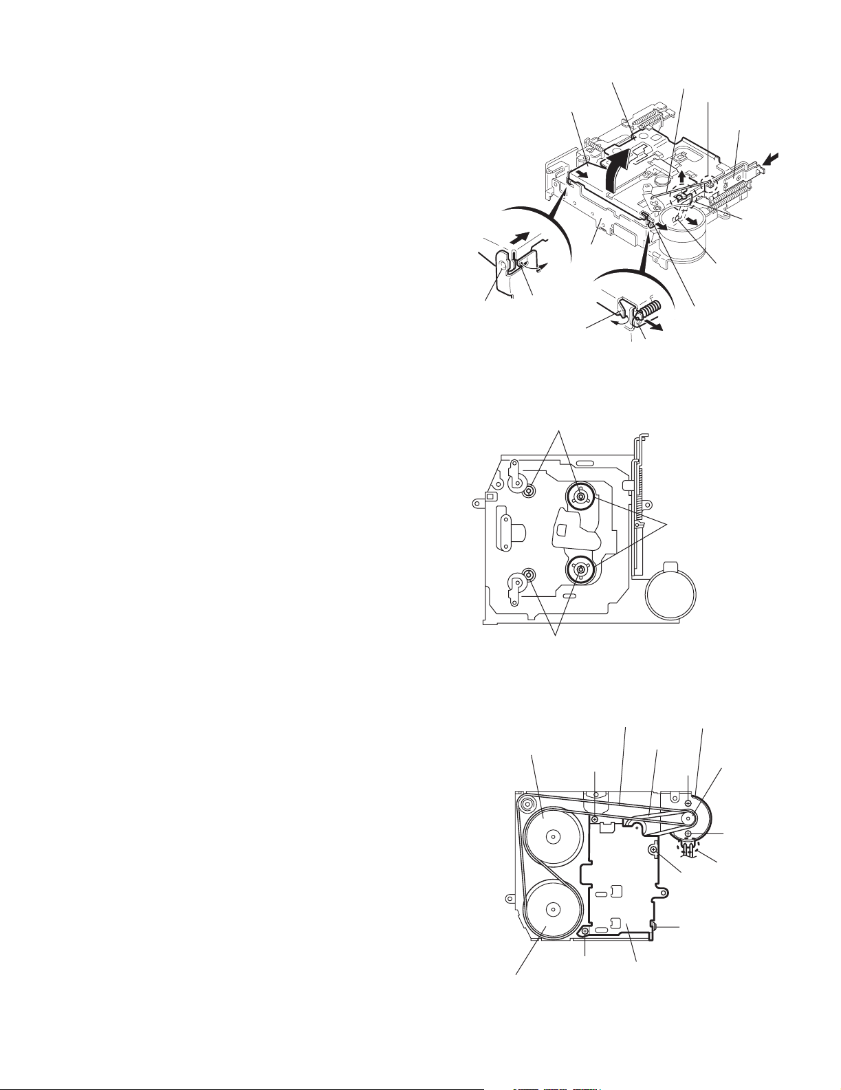
2.2.8 Removing the motor assembly
(See Fig.5)
(1) Unsolder the two wires j on the motor assembly.
(2) Turn over the cassette mechanism assembly and remove
the main belt and the sub-belt from the motor pulley.
ATTENTION:
The main belt can now be removed.
(3) Remove the two screws G attaching the motor assembly.
C washer
Flywheel (BF)
Fig.4
Main-belt
E
Reel disc assembly
Motor assembly
Sub-belt
G
E
Motor pulley
G
Soldering j
Flywheel (BR)
Reel base assembly
E
Fig.5
F
(No.49783)1-9
Page 10
KS-F345
2.2.9 Removing the Flywheel (BF) and (BR) assembly
(See Fig.4 and 5)
• Prior to performing the following procedure, remove the cas-
sette hanger / cassette holder.
(1) From the upper side of the cassette mechanism assembly,
remove the C washer from each shaft of the flywheel (BF)
and (BR).
(2) Turn over the cassette mechanism assembly and remove
the main belt. Pull out the flywheel (BF) and (BR) downward respectively.
C washer
Reel disc assembly
C washer
Fig.4
Main-belt
Motor assembly
2.2.10 Removing the reel base assembly
(See Fig.5 and 6)
(1) Raise the part k of the reel base assembly slightly and re-
move the selector link (B) on the front side of the cassette
mechanism assembly by turning it as shown in Fig.6.
(2) Remove the three screws E and the one screw F on the
underside of the cassette mechanism assembly.
ATTENTION:
The reel base assembly is not repairable. Handle with care.
Pinch-roller (R) assembly
k
Selector link (B).
Turn the selector link (B).
Fig.6
Inside of the reel base assembly
Flywheel (BF)
Flywheel (BR)
Sub-belt
E
Reel base assembly
E
Fig.5
G
E
F
Motor pulley
G
Soldering j
Fig.7
1-10 (No.49783)
Page 11
KS-F345
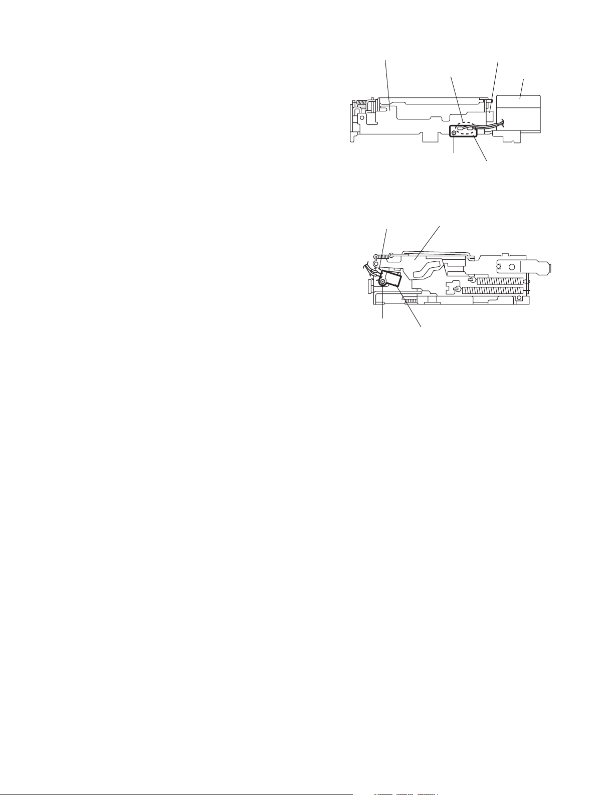
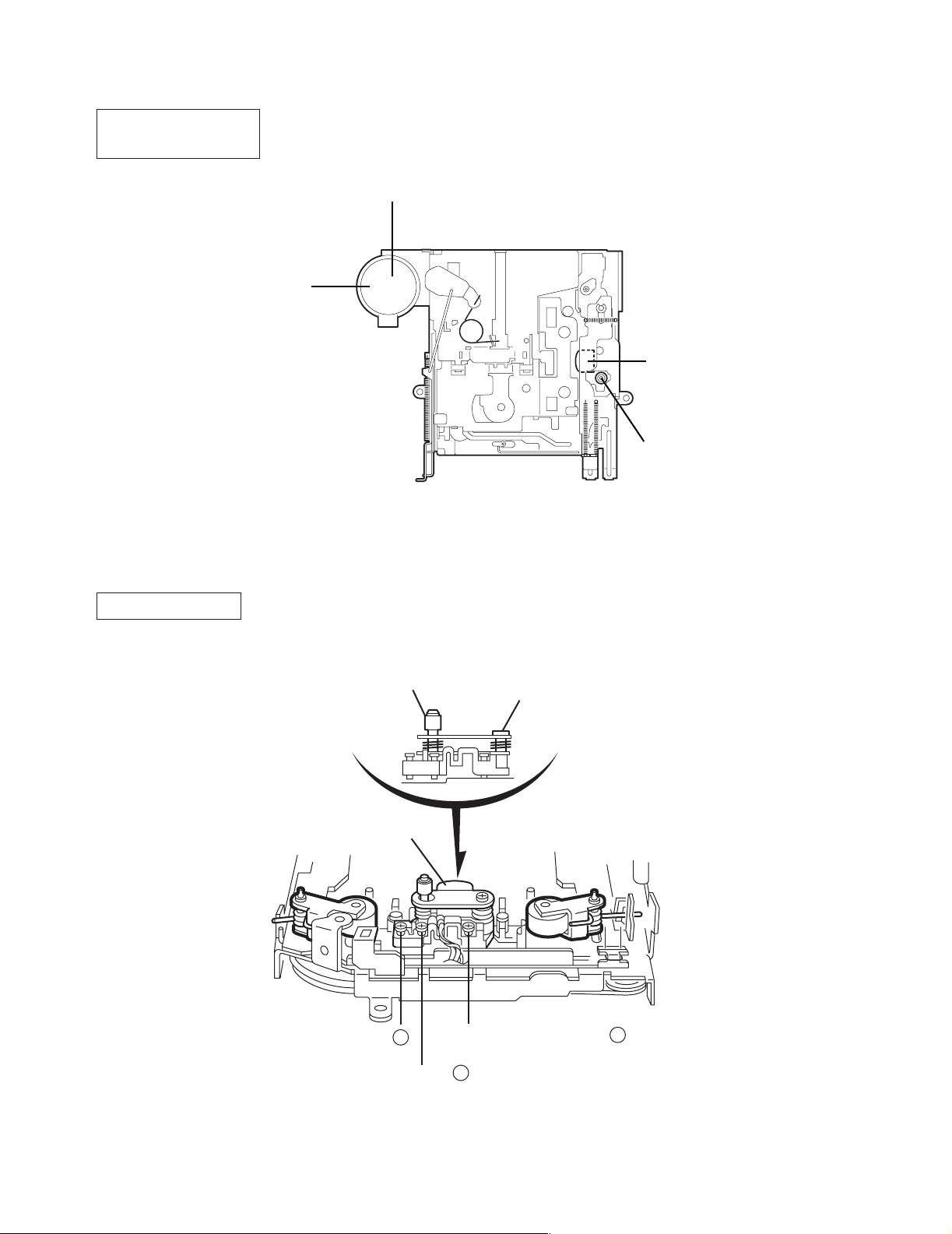
2.2.11 Removing the mute switch board
(See Fig.8)
(1) Unsolder the two wires l on the mute switch board on the
back of the cassette mechanism assembly.
(2) Remove the screw H attaching the mute switch board.
2.2.12 Removing the power switch
(See Fig.9)
• Prior to performing the following procedure, remove the motor
assembly.
(1) Unsolder the two wires m on the power switch on the side
of the cassette mechanism assembly.
(2) Remove the screw I attaching the power switch.
Cassette mechanism assembly
Soldering l
H
Fig.8
Soldering m
I
Cassette mechanism assembly
Power switch
Fig.9
Rower switch
Motor assembly
Mute switch board
(No.49783)1-11
Page 12
KS-F345
3.1 Adjustment method
Test instruments reqired for adjustment Standard volume position
1. Digital oscilloscoe(100MHz)
2. Frequency counter meter
3. Electric voltmeter
4. Wow & flutter meter
5. Test tapes
VT724.......................for DOLBY level measurement
VT739............For playback frequency measurement
VT712....For wow flutter & tape speed measurement
VT703.....................For head azimuth measurement
6. Torque gauge...................Cassette type for CTG-N
(Mechanism adjustment)
SECTION 3
Adjustment
Balance and Bass, Treble volume, Fader
: Center(Indication"0")
Loudness, Dolby NR, Sound, Cruise : Off
Volume position is about 2V at speaker output with
following conditions, Playback the test tape VT721.
AM mode 999kHz/62dB, INT/400Hz, 30%
modulation signal on recieving.
FM mono mode 97.9MHz/66dB, INT/400Hz, 22.5kHz
deviation pilot off mono
FM stereo mode 1kHz, 67.5kHz dev.pilot 7.5kHz dev
Output level 0dB (1 V,50 /open terminal)
Measuring conditions(Amplifier section)
Power supply voltage.............. DC14.4V(11V to 16V allowance)
Load impedance............ 4 (4 to 8 allowance)
Line out level/Impedance..............1.0V/20k load (250 nWb/m)
Frequency band
87.5 MHz to 108.0 MHz
65.0 MHz to 74.0 MHz
522 kHz to 1620 kHz
MW
144 kHz to 279 kHz
LW
Band
FM1/FM2
FM3
AM
1-12 (No.49783)
Page 13
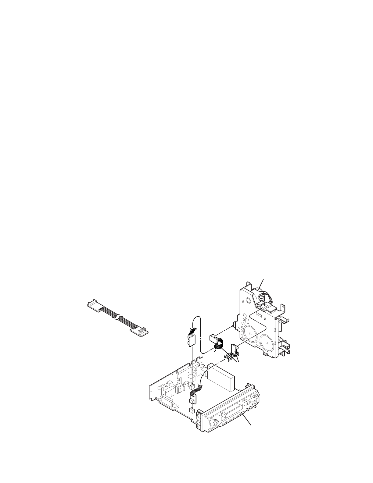
Information for using a car audio service jig
1. For 1995 and 1996, we're advancing efforts to make our extension cords common for all car audio products.
Please use this type of extension cord as follows.
2. As a U-shape type top cover is employed, this type of extension cord is needed to check operation of the
mechanism assembly after disassembly.
3. Extension cord : EXTKSRT002-6P ( 6 pin extension cord ) For connection between mechanism assembly
and main board.
4. Check for mechanism driving section such as motor ,etc..
Disassembly method
1. Remove the front panel assembly.
2. Remove the bottom cover.
3. Remove the front chassis.
4. Remove the two screws D of the rear panel. (Refer to Disassembly method.)
5. Remove the heat sink.
6. Reattach the heat sink with two screws B. (Refer to Disassembly method.)
7. Install the front chassis and front panel assmbly.
8. Confirm that current is being carried by connecting an extension cord jig.
Note
Available to connect to the CJ701 connector when installing the front panel.
KS-F345
CAUTION :
Be sure to attach a heat sink on the power amplifier IC of a main board when supplying the power.
If voltage is applied without attaching the heat sink, the power amplifier IC will be destroyed by heat.
Cassette mechanism
EXTKSRT002-6P
Extension cord
: EXTKSRT002-6P
Main board
Front panel assembly
(No.49783)1-13
Page 14
KS-F345
Arrangement of adjusting & test points
Cassette mechanism
(Surface)
Motor assembly
Tape speed adjust
Playback head
Azimuth screw
Head section view
Head azimuth screw
Playback head
Height adjusting screw
c
Fixed screw
Height adjusting screw
a
1-14 (No.49783)
Height adjusting screw
b
Page 15
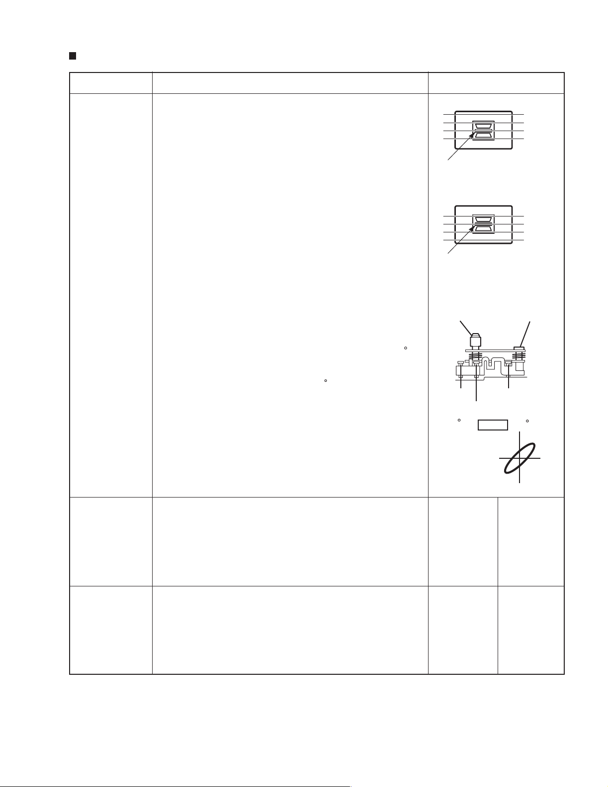
Mechanism adjustment section
Item Adjusting & Confirmation Methods Adjust Std. Value
1.Head azimuth
"Head Height Adjustment"
Note
Adjust the azimuth directly. When you adjust the height using a mirror tape, remove the cassette housing from the
mechanism chassis.
After installing the cassette housing, perform the azimuth
adjustment.
Head shield
KS-F345
A Line
1.Load the mirror tape ( SCC-1659 ). Adjust with height
adjustment screw (a) and azimuth adjustment screw (b) so
that line "A" of the mirror tape runs in the center between
Lch and Rch in the reverse play mode.
2.After switching from REV to FWD then to REV, check that
the head position set in procedure "1" is not changed.
*If the position has shifted, adjust again and check.
3.Adjust the azimuth screw (b) so that line "B" of the mirror
tape runs in the center between Lch and Rch in the forward
play mode.
"Head Azimuth Adjustment"
1.Load the test tape ( VT724: 1kHz ) and play it back in the
reverse play mode. set the Rch output level to maximum.
2.Load the test tape ( VT703: 10kHz ) and play it back in the
forward play mode. Adjust the Rch and Lch output levels
to maximum, with azimuth adjustment screw (b).
In this case, the phase difference should be within 45 .
3.Engage the reverse mode and adjust the output level to
maximum, with azimuth adjustment screw (c).
*The phase diff
erence should be 45 or more.
4.When switching between forward and reverse modes, the
difference between channels should be within 3dB.
*Between FWD Lch and Rch, REV Lch and Rch.
5.When the test tape ( VT721 : 315Hz ) is played back, the
level difference between channels should be within 1.5dB.
The head is at low position
during FWD.
B Line
Head shield
The head is at height position
during REV.
Head azimuth
screw
screw (c)
screw (b)
0
Phase
Fixed screw
screw (a)
45
2.Tape Speed and
Wow & Flutter
3.Playback
Frequency
response
1.Check to see if the reading of the frequency counter & Wow
flutter meter is within 2940-3090 Hz( FWD/REV ), and less
than 0.35% ( JIS RMS ).
2.In case of out of specification, adjust the motor with a builtin volume resistor.
1.Play the test tape ( VT724 : 1kHz ) back and set the volume
position at 2V.
2.Play the test tape ( VT739 )back and confirm 0
+
3dB at1kHz/
-
8kHz and -4+2dB at 1kHz/125Hz.
3.When 8kHz is out of specification, it will be necessary to
readjust the azimuth.
Built-in
volume resistor
Tape Speed
2940-3090Hz
Wow&Flutter
Less than
0.35%
(JIS RMS)
Speaker out
1kHz/8kHz
+
: 0dB 3dB,
-
125Hz/1kHz
: -4dB+2dB,
(No.49783)1-15
Page 16
KS-F345
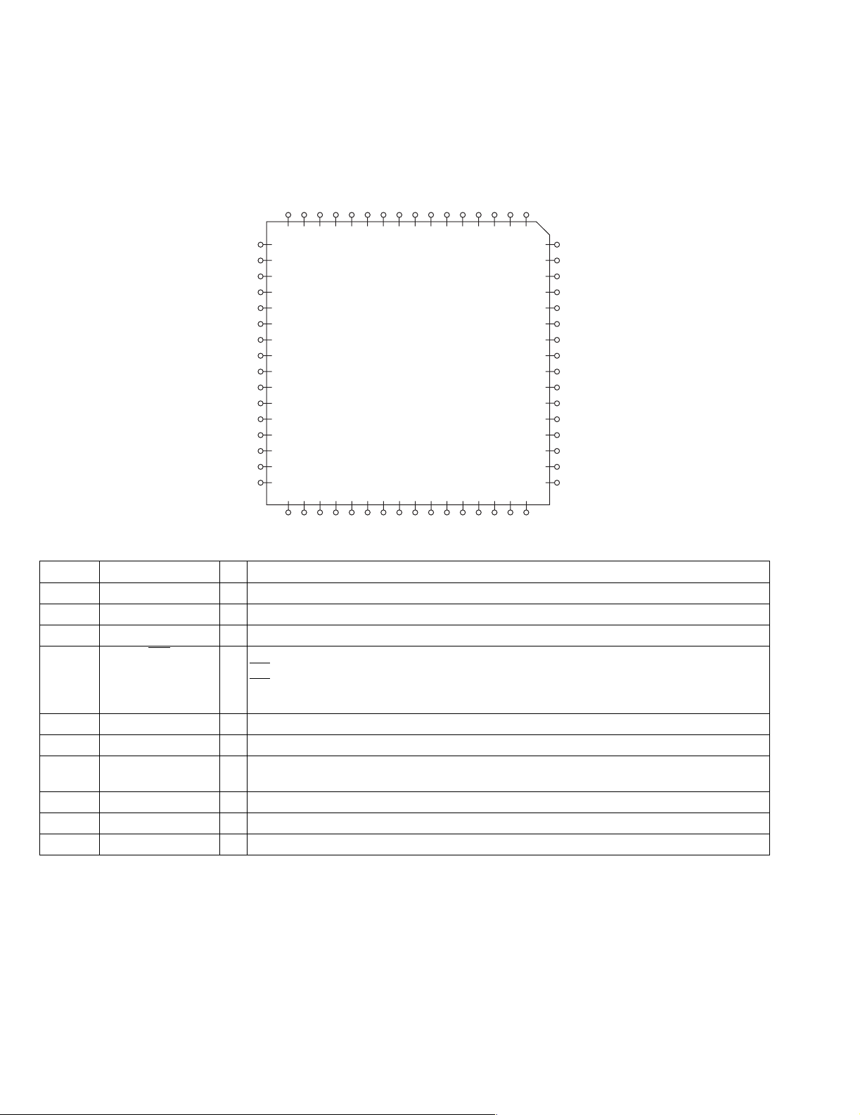
4.1 LC75823W (IC651) : LCD driver
• Pin Layout & Symbol
S8
S9
S10
S11
S12
S13
S14
S15
S16
SECTION 4
Description of major ICs
DATA
CLOCKCEOSC
64 63 62 61 60 59 58 57 56 55 54 53 52 51 50 49
1
2
3
4
5
6
7
8
9
10
11
12
13
14
15
16
17 18 19 20 21 22 23 24 25 26 27 28 29 30 31 32
Vss
INH
VDD
COM3
COM2
COM1
S52
S51
S50
S49
48
47
46
45
44
43
42
41
40
39
38
37
36
35
34
33
S48
S47
S46
S45
S44
S43
S42
S41
S40
S39
S38
S37
S36
S35
S34
S33
S17
S18
S19
S20
S21
S22
S23
S24
S25
S26
S27
S28
S29
S30
S31
• Pin function
S32
Pin No. Symbol I/O Functions
1 to 7 -- Non connect
8 to 52 S8 to S52 O Common driver output pins. The frame frequency is given by : t0=(fosc/384)Hz.
53 S53 to S55 -- Power supply connection. Provide a voltage of between 4.5 and 6.0V.
57 INH
I Display turning off input pin.
="L" (Vss) ----- off (S1 to S52, COM1 to COM3="L"
INT
INT="H" (VDD)----- on
Serial data can be transferred in display off mode.
58, 59 Non connect
60 Vss -- Power supply connection. Connect to GND.
61 OSC I/O Oscillator connection.
An oscillator circuit is formed by connecting an external resistor and capacitor at this pin.
62 CE I Serial data interface connection to the controller. CE : Chip enable
63 CLOCK I Serial data interface connection to the controller. CL : Sync clock
64 DATA I Serial data interface connection to the controller. DI : Transfer data
1-16 (No.49783)
Page 17
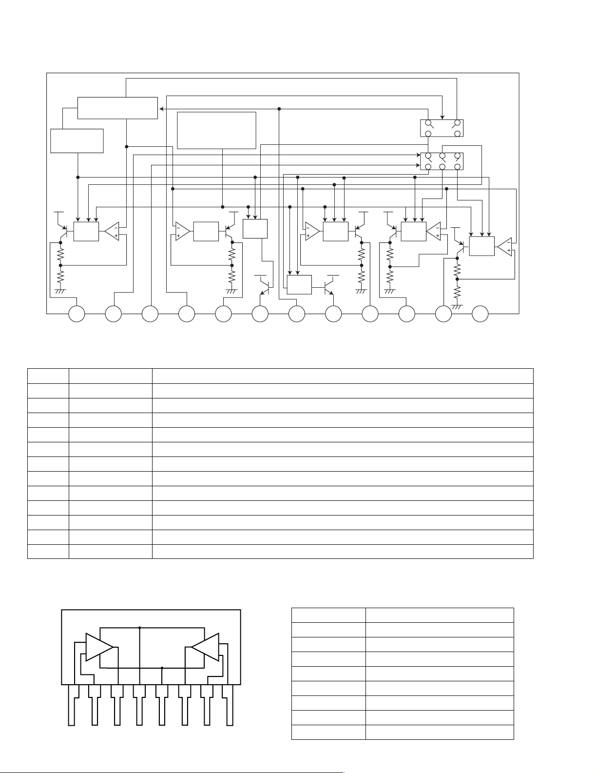
4.2 LC72362N-9B40 (IC701) : Micon
•Pin layout
24 - 1
25
-
KS-F345
80
-
40
64
41 - 64
• Pin functions
Pin No. Symbol I/O Function
1 XIN I Crystal oscillator
2GND-To GND
3 J BUS SI I Bus serial data input from CP751
4 J BUS SO O Bus serial data output to CP751
5 J BUS SCK O Bus serial clock output to CP751
6 J BUS I/O SEL O BUS I/O switch signal output
7 NC - Non connect
8 LCD SO O Serial data output to IC651
9 LCD SCK O Serial clock output to IC651
10 LCD CE O Chip enable output to IC651
11 NC - Non connect
12 E.VOL SO O Serial data output
13 E.VOL SCK O Serial clock output
14 CE O Non connect
15 TUNER ILLUM - Non connect
16 TAPE ILLUM - Non connect
17 CD ILLUM - Non connect
18 DIMMEROUT - Non connect
19 NC - Non connect
20 NC - Non connect
21 NC - Non connect
22 NC - Non connect
23 NC - Non connect
24 NC - Non connect
25 KS1 - Non connect
26 KS0 O Initializing output port
27 K3 I Initializing input port
28 K2 I Initializing input port
29 K1 - Non connect
30 K0 I Initializing input port
31 Vdd - Power supply
32 TEST I Test iput
33 NC - Non connect
34 SEEK/STOP O Output the "If signal request"
35 MONO O Monaural and stereo change
over output
36 R/T - Non connect
37 NC - Non connect
38 POWER CNT O Power control output
39 NC - Power supply
40 NC - Non connect
41 IF CONT - IFC control
Pin No. Symbol I/O Function
42 NC - Non connect
43 NC - Non connect
44 NC - Non connect
45 NC - Non connect
46 NC - Non connect
47 NC - Non connect
48 TAPE IN I H:RADIO L:TAPE
49 F/R SENCE I FORWARD/REVERSE switch
detector
50 TAPE MUTE I DIR.FF/REW.MUTE
51 SD/ST I Station detector and ST input
52 NC - Non connect
53 DETACH I Detection of Front Panel
54 NC - Non connect
55 J BUS INT - Non connect
56 REMOCON - TO GND
57 FM/AM I Change over the FM/AM iuput
58 DOLBY - Non connect
59 NC - Non connect
60 MUTE - The mute time is controlled by
the connected capacitor when
changing over the FM/AM
61 MEMORY DET I Memory detector input
62 LEVEL METER I Non connect
63 SMETER I Signal meter input
64 KEY 2 I Momentary key input
65 KEY 1 I Momentary key input
66 KEY 0 I Momentary key input
67 ACCDET I ACC DET
68 SENS - To GND
69 NC - Non connect
70 FM/AM IF COUNT - AM/FM Frequency detection
71 NC - Non connect
72 NC - Non connect
73 Vdd - Power supply
74 AM OSC - Non connect
75 FM OSC I Input the local oscillator signal of
FM
76 Vss - Connect to GND
77 NC O Non connect
78 EO O PLL Error signal output
79 TEST 1 - To GND
80 XOUT O Crystal oscillator
(No.49783)1-17
Page 18
KS-F345
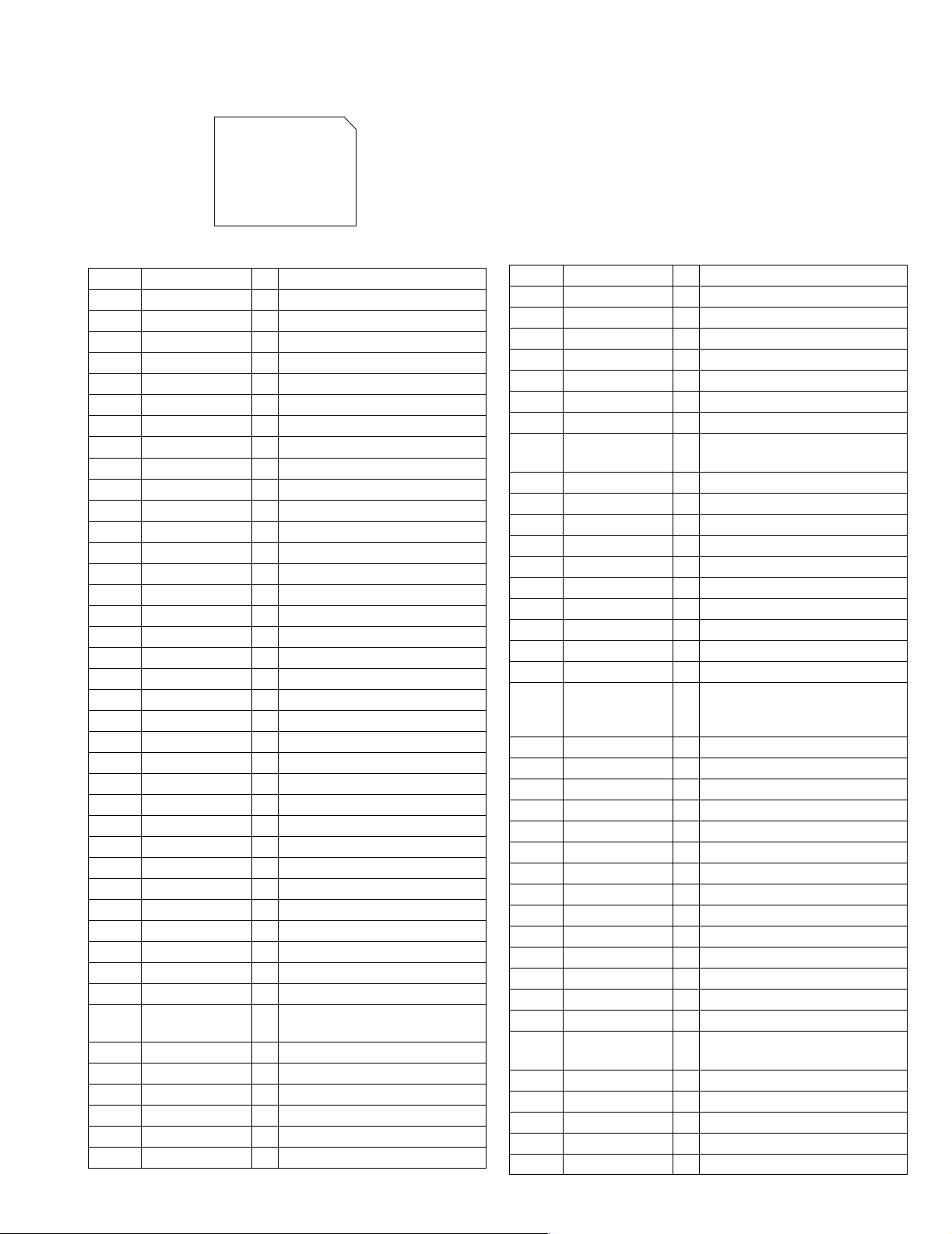
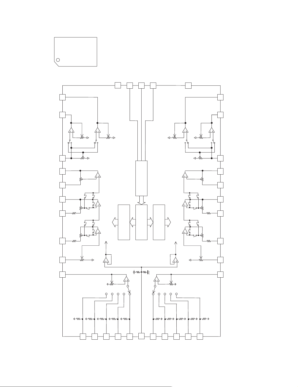
4.3 LC75421M-X (IC931): E. volume
• Pin layout
36 ~ 19
1 ~ 18
• Block diagram
10
3
2
4
5
6
7
8
9
36
1
CCB
INTERFACE
35
34
33
32
31
30
29
28
11
12
13
14
15
16
LVref
CONTROL
17
CIRCUIT
18
LOGIC
CIRCUIT
19
CIRCUIT
CONTROL
RVref
222120
23
27
26
25
24
1-18 (No.49783)
Page 19

• Pin functions
Pin No Symbol Function
1 DI Serial data input terminal for control
2 CE Chip enable terminal
3 VSS GND
4 LROUT Rear Lch fader output terminal
5 LFOUT Front Lch fader output terminal
6 LFIN Front Lch input terminal
7 LOUT C & R connection terminal for super bass band
8 LSB C & R connection terminal for super bass band
9 LBASS2 C & R connection terminal for bass band
10 LBASS1 C & R connection terminal for bass band
11 LTRE Capacitor connection terminal for treble band filter
12 LIN Lch input terminal
13 LSELO Input selector output terminal
14 L5 input signal terminal
15 L4 input signal terminal
16 L3 input signal terminal
17 L2 input signal terminal
18 L1 input signal terminal
19 Vref Power supply for analog GND
20 R1 input signal terminal
21 R2 input signal terminal
22 R3 input signal terminal
23 R4 input signal terminal
24 R5 input signal terminal
25 RSELO Input selector output terminal
26 RIN Rch input terminal
27 RTRE Capacitor connection terminal for treble band filter
28 RBASS1 C & R connection terminal for bass band filter
29 RBASS2 C & R connection terminal for bass band filter
30 RSB C & R connection terminal for super bass band filter
31 ROUT C & R connection terminal for super bass band filter
32 RFIN Rch input terminal
33 RFOUT Front Rch fader output terminal
34 RROUT Rear Rch fader output terminal
35 VDD Power supply terminal
36 CL Serial clock output terminal for control
KS-F345
(No.49783)1-19
Page 20
KS-F345
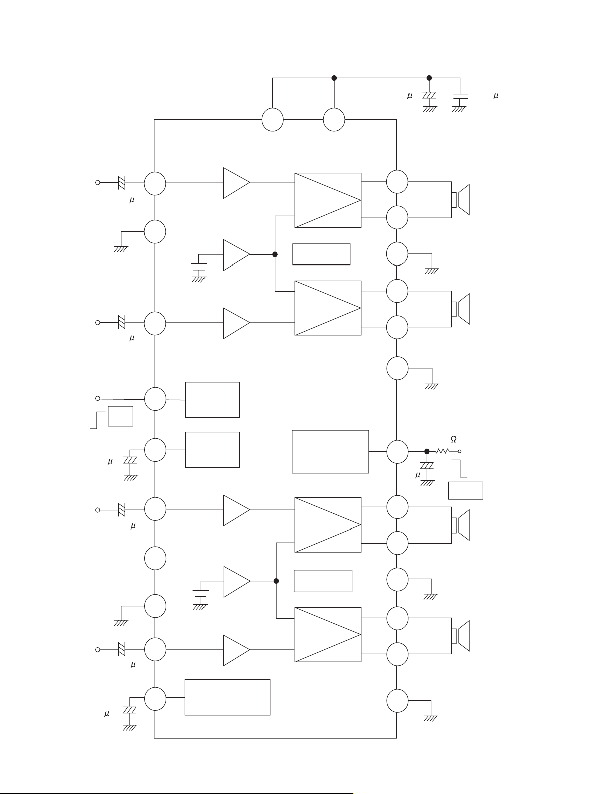
4.4 LA4743K (IC981) : Power amp.
• Block diagram
IN 1
TAB
IN 2
+
0.22 F
+
0.22 F
11
1
12
Vcc 1/2 Vcc 3/4
6 20
-
+
Protective
circuit
-
+
2200 F 0.022 F
+
9
7
+
OUT 1+
OUT 1-
PWR GND1
8
+
OUT 2+
5
-
OUT 2-
3
PWR GND2
2
ST BY
R.F
47 F
IN 3
PRE GND
IN 4
+5V
ST ON
+
0.22 F
N.C
+
0.22 F
4
Stand by
Switch
Mute
10
+
Ripple
Filter
Mute
22
circuit
3.3 F
+
15
-
+
-
17
19
10K
+
OUT 3+
OUT 3-
Low Level
Mute ON
25
18
21
23
PWR GND3
OUT 4+
OUT 4-
13
14
Protective
circuit
-
+
+
-
ON TIME C
1-20 (No.49783)
22 F
Muting &
16
+
ON Time Control
Circuit
PWR GND4
24
Page 21
• Terminal layout
TAB
GND
FR-
STDBY
FR+
VP1
RR-
GND
RR+
RIPPLE
INRF
INRR
SGND
FLIN
RLIN
DNTIME
RL+
GND
RL-
VP3
FL+
MUTE
FL-
GND
NC
• Pin function
Pin No. Symbol Function
1 TAB Header of IC
2 GND Power GND
3 FR- Outpur(-) for front Rch
4 STDBY Stand by input
5 FR+ Output (+) for front Rch
6 VP1 Power input
7 RR- Output (-) for rear Rch
8 GND Power GND
9 RR+ Output (+) for rear Rch
10 RIPPLE Ripple filter
11 RRIN Rear Rch input
12 FRIN Front Rch input
14 FLIN Front Lch input
15 RLIN Rear Lch input
16 ONTIME Power on time control
17 RL+ Output (+) for rear Lch
18 GND Power GND
19 RL- Output (-) for rear Lch
20 VP3 Power input
21 FL+ Output (+) for front
22 MUTE Muting control input
23 FL- Output (-) for front
24 GND Power GND
25 NC Non connection
KS-F345
(No.49783)1-21
Page 22
KS-F345
4.5 AN80T05LF (IC781) : Regulator
• Pin layout & Block diagram
Reference Voltage
Thermal
Protection
ASO & Peak
Current Protection
Pre
Drive
Pre
Drive
AMP
Out
AMP
Out
Pre
Drive
123456789101112
ILL
MODE2 MODE1 STB VDD
10V
5.6V
AMP VCC ANT COM
8.7VAM8.7VFM8.7V
• Pin function
Pin No. Symbol Function
1 ILL 10V power supply for illumination.
2 MODE2 When 5V is input,becomes AM. and the antenna output is turned on.
3 MODE1 When 5V is input,becomes AM. and the output of FM is switched.
4 STB When 5V is input outputs to ILL,COM and AMP. It is 0V usually.
5 VDD 5.6V power supply.
6 AMP Power supply supply to remote amplifier
7 VCC Back up. connects with ACC with it.
8 ANT Power supply supply to auto antenna.
9 COM 8.7V power supply.
10 AM The power supply of 8.7V to AM.
11 FM The power supply of 8.7V to FM.
12 GND Ground
Pre
Drive
Pre
Drive
GND
4.6 UPC1228HA (IC901) : Head amp
• Pin layout & Block diagram • Pin function
Pin No. Symbol
1 Input 1
AMP1 AMP2
2 Negatice feed back 1
3 Output 1
4 Power supply; +Vcc
1
2345678
5 Ground
6 Output 2
7 Negative feed back 2
8 Input 2
1-22 (No.49783)
Page 23

KS-F345
(No.49783)1-23
Page 24

KS-F345
VICTOR COMPANY OF JAPAN, LIMITED
AV & MULTIMEDIA COMPANY 10-1,1chome,Ohwatari-machi,Maebashi-city,371-8543,Japan
(No.49783)
Printed in Japan
200303WPC
Page 25
SCHEMATIC DIAGRAMS
CASSETTE RECEIVER
KS-F345
CD-ROM No.SML200303
KS-F345
Contents
Block diagram
Standard schematic diagrams
Printed circuit boards
S.BASS
FM
SEL
DISP
AM
SSM
EX
SCMMO
Area Suffix
EE ---- Russian Federation
2-1
2-2
2-5,6
COPYRIGHT 2003 VICTOR COMPANY OF JAPAN, LTD.
No.49783SCH
2003/03
Page 26

KS-F345
Safety precaution
!
Burrs formed during molding may be left over on some parts of the chassis. Therefore,
pay attention to such burrs in the case of preforming repair of this system.
Page 27
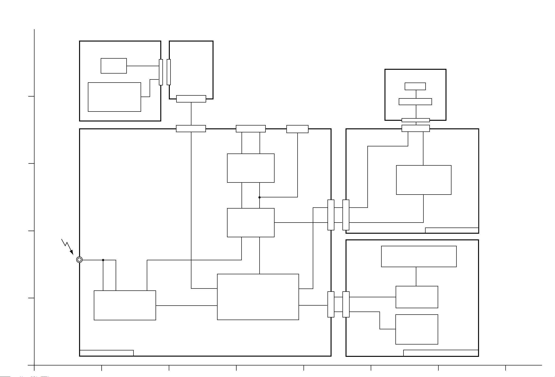
Block diagram
5
4
DIRECTION BOARD
MAIN
MOTOR
MUTE SWITCH
TAPE/RADIO SW
CP722
RELAY
BOARD
CP721
CN721
TO
SPEAKER
CONNECTOR
CP981
LINE REAR OUT
CJ921
KS-F345
HEAD
PROG-SW
CJ901
Lch Front
Lch Rear
Lch Rear
Lch
Rear OUT
F/R
LCH
IC981
POWER AMP.
IC901
HEAD AMPLIFIER
Lch RearLch Front
3
IC931
E.VOLUME
TAPE L
CN901
CP901
ANT
2
J1
FM
AM
TAPE IN
PROG
TUNER L
CE
DATA
CLK
IC701
TU1
AM/FM TUNER PACK
SEEK/STOP, MONO,
SD/ST, S METER,
FM OSC, EO, BAND
SYSTEM CONTROL MICON
F/R
CJ701
DATA
CLOCK
CE
KEY0 - 2
CP701
LCH
HEAD AMP SECTION
LCD1
S3 - S47
COM1 - COM3
IC651
LCD DRIVER
KEY
S601 - S606
1
S608 - S612
S614 - S621
MAIN AMP SECTION
LCD & KEY CONTROL SECTION
AB CD E F G
2-1
Page 28

Standard schematic diagrams
Main amp section
5
4
To
LCD & Key control
section CP701
J1
QNZ0009-001
C772
2.2/50
C773
0.001
Q772
KTC3199/GL/-T
R774
1.5K
R773
1K
Q771
KTC3199/GL/-T
R772
Q3
R771
4.7K
10K
D792
MTZJ9.1C-T2
C771
D771
1SS119-041
220/10
R17
2.2K
R6
D791
2SA1706/ST/-TKTA1267/YG/-T
10K
1SS119-041
R1
R2
R3
L1
4.7uH
Q1
R5
Q2
KRC102M-T
10
1K
1K
1K
TU1
D1
1SS119-041
10K
R4
TU-9V
BAND
QAU0221-001
D2
1SS119-041
220/10
EO
C786
0.1/50
C3
KS-F345
1SS119-041
D973
10/16
0.022
0.022
0.1/50
0.022
C2
C5
0
B69
IFC/C
FM.OSC
10K
C6
C7
C4
R9
R10
10k
0.01
C11
Q4
KRC102M-T
SK/ST
0.1/50
C8
470
470
R51
0.01
C15
R52
5.6k
S.METER
C131
R61
1/50
1/50
C231
R14
8.2k
R15
Q5
22k
KRC102M-T
MONO
SO/ST
MUTE
C9
0.01
R62
5.6k
IF.C
D990
MTZJ11B-T2
C972
KS-F345
Q972
KRA102M-T
C988
220/10
47/16
Q989
KRA102M-T
ACC.MUTE
MUTE2
D161
1SS119-041
D261
1SS119-041
CJ921
R163
LRO
820
R165
2.2K
R265
2.2K
820
R263
RRO
QNN0519-001
R164
100
2SD2144S/VW/-T2SD2144S/VW/-T
Q261 Q161
R264
100
Parts are safety assurance parts.
When replacing those parts make
sure to use the specified one.
TUNER SIGNAL
TAPE SIGNAL
FRONT SIGNAL
REAR SIGNAL
CJ701
VMC0334-001
3
To
Head amp
section CP721
CN721
QGB1214J1-06S
2
To
Head amp
section CP901
CN901
QGB1214J1-06S
1
R719
R718
R720
L783
47uH
3.3K
3.3K
3.3K
D705
D704
D711
MTZJ6.2B-T2
MTZJ6.2B-T2
MTZJ6.2B-T2
R704
R705
D786
1A3G-T1
D706
D707
MTZJ6.2B-T2
MTZJ6.2B-T2
D718
1SS119-041
10K
KTC3199/GL/-T
47K
R715
C709
C710
D708
D709
0.1
MTZJ6.2B-T2
MTZJ6.2B-T2
Q701
2.2k
0.47/50
LCD.SO
LCD.SCK
LCD.CE
DETACH
TAPE14V
TAPEIN
TAPE.L
TAPE.R
KEY2
KEY1
KEY0
PROG
5V
14V
CE
R5V
D713
1SS119-041
TAPEIN
F/R
IC701
LC72362N-9B40
SD/ST
PROG
R727
SK/ST
MONO
9V
F/R
47K
47K
R725
47K
R708
R702
47K
47K
R703
47K
R707
IFC/C
CL
DI
R724
DETACH
4.7K
LCD.CE
LCD.SCK
BAND
TUL
LCD.SO
TUR
MUTE
MEM.DET
S.METER
KEY2
R710
R709
R712
C706
C12
0.01
270P
4.7K
4.7K
4.7k
5V
X701
QAX0406-001Z
D716
1SS119-041
4.7k
4.7k
R714
R713
C702
22P
C701
27P
FM.OSC
47K
R726
100/6.3
0.22
KRC102M-T
C703
IF.C
KEY0
KEY1
C704
Q783
TUR
TAPE.L
EO
TAPE.R
9V
C705
10/16
TAPE14V
14V
MEM.DET
R5V
5V
TU-9V
Q784
2SA1706/ST/-T
R786
1K
C232
1/50
C132
1/50
L782
47uH
R785
C934
22/16
RB721Q-40-T2
47K
TUL
R792
6.8
D961
Q789
C943
1/50
L781
47uH
KRA102M-T
R789
R790
470K
C933
100K
C134
0.082
C942
0.0015
0.0015
1/50
C234
R795
47K
R796
IC931
LC75421M-X
0.082
C235
R232 R132
Q782
1SS119-041
D781
18K
C783
C135
0.082
C236
7.5k 7.5k
2SA1706/ST/-T
1K
R784
Q781
KRC102M-T
R990
2200/6.3
R131
C137
C136
0.15
0.082
C237
R783
Q987
KRA102M-T
10K
KRC102M-T
3.9k
0.15
0.15
R231
47K
C784
D782
1SS119-041
Q988
C150
C940
C941
C238
3.9k
R931
1/50
1/50
0.15
220/10
C781
10/16
2.2/50
C250
2.2/50
C160
2.2/50
2.2/50
C260
10
C785
10/16
IC781
AN80T05LF
C987
10/16
CE
R941
3.3k
100/10
C931
1A3G-T1
D784
R985
DI
4.7k
R722
3.3K
C707
LRO
R721
C932
0.01
R999
RRO
0.1
C138
L981
D785
1A3G-T1
47k
R993
27K
C976
0.22
R992
27K
R997
47k
R991
27K
R994
27K
R996
47k
C981
2200/16
D981
IN5401-TM
R787
QQR1367-001
R797
12K
2.4K
R788
C977
0.22
C975
0.22
C995
470P
C994
470P
C974
0.22
LRO-
LRO+
C992
0.1
C997
C985
470P
4.7/25
C996
C983
470P
0.1
R998
C986
47k
22/16
C982
47/16
C989
10/16
R973
4.7K
C991
0.1
RRO-
RRO+
RFO+
RRO+
LRO+
LFO+
RFO-
C984
10/16
ACC.MUTE
RRO-
LRO-
LFO-
100
CL
3.3K
0.1
RFO+
LFO+
C993
0.1
RFO-
R972
2.7K
C990
0.1
IC981
LA4743K
Q971
KRC102M-T
MUTE2
D974
1SS119-041
QNZ0611-001
CP981
QAM0089-001
QMFZ047-150-T
LFO-
2-2
HAB C DE FG
Page 29

KS-F345
LCD & Key control section
5
SW3
SW4
SW5
SW7
SW8
SW9
SW10
SW11
SW12
SW13
SW14
SW15
SW16
SW17
SW18
SW19
SW20
SW21
SW22
SW23
SW24
SW25
SW26
SW27
SW28
SW29
SW30
SW31
SW32
SW33
SW34
SW35
COM1
COM2
COM3
INH
OSC
CE
CLOCK
DATA
S47
SW36
SW37
S46
S3
4
VMC0335-001
CP701
5V
14V
REMOCON
DATA
CLOCK
CE
KEY1
KEY2
R5V
KEY0
SW6
3
D655
10k
R655
10k
R656
10k
R654
MA152WK-X
D654
MA152WK-X
MA152WA-X
D653
R653
180K
D652
MA152WA-X
C651
R651
1.5k
R652
4.7/6.3
0.01
C653
680p
C652
47k
SW38
S45
S4
SW39
S44
S5
SW40
SW41
S43
IC651
LC75823W
S6
S7
SW42
S42
SW43
S41
S8
SW44
SW45
SW46
SW47
COM1
COM2
COM3
S39
S40
S38
S37
S35
S34
S33
S36
S32
S31
S30
S29
S28
S27
S26
S25
S24
S23
S22
S21
S20
S19
S18
S17
S13
S12
S11
S10
S9
S16
S15
S14
2
R649
D613
D619
D620
1.5k
R648
D616
820
820
R647
R646
D617
D618
D614
D615
D610
820
620
R645
560
R644
R643
D611
R601
680
S601
R607
680
S608
R613 R614 R615
680 560
S615
D606
R638
D602
D601
D603
R637
820
R636
1.5k
R635
820
820
10K
R657
D657
MA152WK-X
IC652
RPM6938-SV4
C654
4.7/6.3
47
R658
PL601
QLL0151-001
PL603
QLL0151-001
D612
D607
820
R642
D608
R641
820
1.8k
R640
D604
D605
1k
820
R639
S609
S602
S616
R608
R602
560
560
S617
S603
S610
R603
R609
680
680
680
R604 R605
910
S604
R610 R611
910 1.2k
S611
R616
910 1.2k
S618
S605
1.2k
S612
S619
R617
S614
S620
S606
R618
1.5k
S621
1
AB CD E F G
2-3
Page 30

KS-F345
KS-F345
Head amp section
5
CJ901
QGA2002C1-05
4
IC901
UPC1228HA
R101
R104
330k
15k
C105
C104
C103
100p
C102
0.01
100
R103
C101
47/6.3
CP901
QGB1214K1-06S
0.47/50
TAPE SIGNAL
820p
C203
R204
330k
C201
C202
820p
100p
0.47/50
R203
C204
C205
100
47/6.3
R201
0.01
15k
C901
100/10
100
R901
To
Main amp section
CN901
3
CP722
QGA2002F1-06
2
CP721
To
Main amp section
CN721
QGB1214K1-06S
1
2-4
HAB C DE FG
Page 31

Printed circuit boards
Main board
KS-F345
5
L981
CJ921
D981
R718
C14
R715
D708
C232
C13
R719
R709
C934
D709
C709
R702
R703
R792
CP751
C942
R710
CN901
C943
C231
R726
C705
C933
D716
C710
C131
R61 R62
C134
C233
R707
IC701
C704
C703
D786
C12
D771
C10
J1
C771
R771
Q771
R773
C773
R772
TU1
4
L1
D2
D1
3
D704
R2
C11
R14
R3
C2
C3
C5
C4
D792
C6
C7
R10
C15
Q5
D705
C786
D711
D706
R712
R15
C1
Q4
R1
Q772
D791
R713
C133
C772
R774
R7
R52
R51
Q1
R6
R4
Q3
R5
Q2
R17
R9
C8
R714
R725
L782
CJ701
R724
R708
C9
C706
D707
R720
C132
C135
C234
C701
C702
C136
C235
R232
X701
Q261
R971
C137
C707
C236
R131
R761
D261
C940
C238
C237
R265
IC931
R763
C260
D974
R132
C138
R231
Q971
R727
R757
C941
C150
C250
D701
R760
R722
Q161
C751
R721
R931
R165
R972
R752
R941
R263
D961
D713
R759
R756
C160
R785
D714
R163
D161
R789
Q784
C985
D715
R164
L781
R762
C931
Q972
IC751
R996
R994
R758
R999
Q987
Q988
C990
C932
C996
R264
R751
CP981
R998
Q789
R990
R755
R993
D781
D782
R790
R753
C991
R997
R795
R796
R788
C997
R992
C994
C972
R991
L783
R754
R764
D973
C785
C992
C784
R786
Q782
C975
C974
Q989
R783
C977
C976
R973
C995
R784
D990
R704
Q701
IC781
C993
C982
R787
C989
R705
C984
C988
D718
D785
CN721
R797
Q783
C986
D784
C981
R985
C987
C983
IC981
Q781
C783
C781
2
1
AB C
2-5
Page 32

KS-F345
Front board
D601
S620
D608
D605
R616
R615
D604
S621
S619
R611
R618
R617
S614
D606
S618
D602
D603
S601
D619
S602
D620
S603
R603
R602
5
S604
S605
D618
D616
S608
IC652
D617
LCD1
S606
D613
S609
D614
R608
S610
R609
D615
S611
D610
R610
S612
D611
S615
D612
R613
S616
D607
S617
4
Forward side
Reverse side
R654
R655
R656
IC651
R644
R645
D657
PL601
R657
R605
R604
R607
IC652
R601
R649
R648
R647
C654
R646
R658
R635
R653
R642
R636
R637
R651
R643
C652
R614
R639
R638
C651
D655
R640 R641
D654
R652
CP701
C653
D652
D653
PL603
3
2-6
Mecha board
2
(Head amplifier board) (Relay board)
C203
R204
R201
C105
R101
R104
C103
IC901
C205
R103
R203
C104
R901
C901
C102
C204
CP901
C202
C101
C201
CJ901
CP721
CP722
1
AB CD
Page 33

< MEMO >
KS-F345
Page 34

KS-F345
VICTOR COMPANY OF JAPAN, LIMITED
AV & MULTIMEDIA COMPANY 10-1,1Chome,Ohwatari-machi,Maebashi-city,371-8543,Japan
(No.49783SCH)
Printed in Japan
2003/03
Page 35

PARTS LIST
[ KS-F345 ]
* All printed circuit boards and its assemblies are not available as service parts.
Area suffix
KS-F345
EE --------- Russian Federation
- Contents -
Exploded view of general assembly and parts list (Block No.M1) --------------------- 3-2
Cassette mechanism assembly and parts list (Block No.MP) -------------------------- 3-4
Electrical parts list (Block No.01~03) ---------------------------------------------------------- 3-8
Packing materials and accessories parts list (Block No.M3,M5) ---------------------- 3-12
No. 49783 3-1
Page 36

KS-F345
Exploded view of general assmbly and parts list
54
14
56
57
53
Block No.
M
M
1
M
B
A
Main board
24
11
49
15
20
15
23
19
17
44
43
22
21
44
10
47
50
45
48
LCD1
46
55
14
52
51
9
13
16
13
A
7
B
2
3
18
17
8
5
38
4
1
4
12
6
12
4
37-3
12
34
4
36
30
Front board
33
27
40
25
29
37-2
35
28
42
39
37-1
26
32
41
31
3-2
5
Page 37

Exploded view of general
Assembly and parts list
Block No. [M][1][M][M]
Symbol No.
1 ------------ CDS-363 MECHA
2 VKL7821-001 EJECT LEVER
3 QYSPSPT2625Z SCREW 2.6mm x 2.5mm
4 QYSDSP2604Z SCREW 2.6mm x 4mm(x4)
5 QYSDST2605Z SCREW 2.6mm x 5mm(x2)
6 GE20134-001A MECHA BKT
7 GE10043-011A TOP CHASIS
8 GE40135-001A EARTH PLATE
9 GE30568-006A HEAT SINK
10 GE30393-001A BOTTOM COVER
11 FSMA3004-203 INSULATOR
12 QYSDST2604Z SCREW 2.6mm x 4mm(x4)
13 FSKZ4005-001 SCREW (x2)
14 QYSDST2604Z SCREW 2.6mm x 4mm(x2)
15 QYSDST2606Z SCREW 2.6mm x 6mm(x2)
16 QYSDST2612Z SCREW 2.6mm x 12mm(x2)
17 QYSDST2004M MINI SCREW 2mm x 4mm(x2)
18 GE10053-001A FRONT CHASSIS
19 GE30583-001A LOCK LEVER
20 FSKW4005-003 TORSION SPRING
21 FSXP3026-002 RLS KNOB
22 FSKW3002-004 COMP. SPRING
23 FSJC3014-002 CASSETTE LID
24 VKW4947-002 DOOR SPRING
25 GE10051-001A FRONT PANEL
26 GE30584-007A FINDER ASSY
27 FSJK3014-001 LIGHT LENS
28 GE20119-001A PRESET BUTTON
29 FSYH4036-077 SHEET
30 GE30304-001A POWER BUTTON
31 GE20131-021A D.FUNC BUTTON
32 GE30307-001A SND FTN BUTTON
33 FSYH4036-032 SHEET
34 GE20130-031A PUSH BUTTON
35 GE20120-002A UP/DOWN BUTTON
36 GE20118-002A +/- BUTTON
37 FSXP4007-00A BUTTON ASS'Y
38 FSKW3002-003 COMP. SPRING
39 FSKW3002-003 COMP. SPRING
40 FSKW3002-003 COMP. SPRING
41 GE30306-001A DETACH BUTTON
42 FSKW3002-012 COMP.SPRING
43 GE10052-001A REAR COVER
44 VKZ4777-001 MINI SCREW (x4)
45 FSJK3033-001 LCD LENS
46 GE30309-002A LCD CASE
47 FSKS3020-003 LENS CASE
48 FSYH4075-003 LIGHTING SHEET
49 GE30645-001A NAME PLATE
50 QNZ0440-001 LCD CONNECTOR
51 GE40136-001A IC BRACKET
52 QMFZ047-150-T FUSE 15A
53 GE30382-015A REAR BRACKET
54 QYSDST2606Z SCREW 2.6mm x 6mm
55 QYSDSF2606Z SCREW 2.6mm x 6mm(x2)
56 QYSDST2606Z SCREW 2.6mm x 6mm
37-1 FSXP3066-001 FF BUTTON
37-2 FSXP3067-001 REW BUTTON
37-3 FSXP3065-001 EJECT BUTTON
LCD1 QLD0249-001 LCD MODULE
Part No. Part Name Description Local
KS-F345
3-3
Page 38

KS-F345
Cassette mechanism assembly and parts list
81
109
24
66
72
30
CDS-363SJ1
89
120
107
53
23
69
96
123
31
121
68
47
Block No.
19
61
61
M
M
P
M
109
20
73
109
42
40
44
63
54
70
12
38
79
78
39
106
37
49
35
41
21
32
7
77
107
10
117
100
116
1
97
82
57
106
2
105
109
119
45
46
48
50
93
114
26
3
87
115
106
86
109
65
71
122
67
85
25
58
94
110
117
83
76
95
107
118
8
22
62
5
6
101
3-4
107
43
15
9
16
4
117
74
80
Page 39

Cassette mechanism
Block No. [M][P][M][M]
Symbol No.
1 X-0363-1001S MAIN CHASSIS AS
2 X-0363-1002S HEAD PLATE ASSY
3 X-0363-1004S FR CONV ARM (A)
4 X-0363-6001S REEL BASE ASSY
5 X-0363-6007S LEVER BRKT ASSY
6 X-0363-6003S TU GEAR ARM ASS
7 X-0363-6004S PINCH ARM(R) AS
8 X-0363-6005S PINCH ARM(F) AS
9 X-0363-6006S DETECTOR CAM AS (x2)
10 X-0363-2005S REEL SPINDLE AS (x2)
12 X-0036-1019S EJ.CAM LOCK ASY
15 1-0363-6010S FLYWHEEL ASSY F
16 1-0363-6011S FLYWHEEL ASSY R
19 1-0036-1065S FF LEVER(JVC)
20 1-0036-1066S REW LEVER(JVC)
21 1-0036-1007S EJECT LEVER
22 1-0036-1013S LOCK ARM
23 1-0036-1015S SPG SUPPORT PLT
24 1-0036-1018S CENTER PLATE
25 1-0036-1023S CHANGE LEVER(B)
26 1-0036-1026S FR ARM(B)
30 1-0138-1002S CASSETTE HANGER
31 1-0138-1006S ADJUSTER SHIN(X
32 1-0138-1010S CASSETTE HOLDER
35 1-0363-1003S EJECT CAM
37 1-0036-2001S IDLE GEAR
38 1-0036-2003S REDUCT.GEAR(B)
39 1-0036-2004S REDUCT.GEAR(A)
40 1-0036-2007-5S RATCHET
41 1-0036-2009S SENSOR ARM
42 1-0036-2010S SELECTOR GEAR
43 1-0036-2014S DETECTOR GEAR
44 1-0038-2014S GEAR LOCK ARM
45 1-0038-2018S TAPE GUIDE
46 1-0363-2006S ADJUSTER LINK B
47 1-0138-2005-3S ADJUSTER ARM(B)
48 1-0036-2005S PULLEY GEAR
49 1-0032-2007S TAPE HOOKER
50 1-0058-2021-5S IDLE PULLEY(A)
53 1-0363-3018S FF ROLLER
54 1-0036-3018S COLLER
57 1-0363-3007S HP ROLLER(A)
58 1-0363-3011S PROGRAM ROLLER
61 1-0036-4001S FF/REW LEVER SP
62 1-0036-4002S LOCK LEVER SPG
63 1-0036-4003S GEAR LOCK ARM S
65 1-0036-4006S HEAD PLATE SPG
66 1-0036-4007S EJ.CAM LOCK SPG
67 1-0036-4008S PROGRAM ARM SPG
68 1-0036-4010S ADJUST ARM SP(A
69 1-0036-4011S ADJUST ARM SP(B
70 1-0036-4015S DASH SPG
71 1-0036-4017S CHANGING ARM SP
72 1-0036-4023S CENTER PLT SP(B
73 1-0038-4014S RATCHET SPG
74 1-0138-4001S BACK TEMSION SP
76 1-0363-4003S PINCH ARM SPG F
77 1-0363-4004S PINCH ARM SPG R
78 1-0363-4005S EJECT LEVER SPG
79 1-0036-4005S EJECT CAM SPG
80 1-0036-5020S MAIN BELT(AL)
81 1-0363-5007S RETURN LINK
82 1-0036-5001S SUB BELT
83 1-0363-5003S SELECTOR LINK B
85 1-0036-7002S WIRE(A)
86 1-0036-7003S WIRE(B)
87 1-0036-7073S WIRE(AL)
89 X-0363-7006S MOTOR ASSY
93 1-0363-7001S MUTE SW
94 1-0363-7002S SLIDE SW
95 1-0363-7008S SLIDE SW PWB
96 1-0036-7016S HEAD
97 1-0363-7005S POWER SW
100 1-0036-7089S 6P WIRE ASY(JVC
Part No. Part Name Description Local
Symbol No.
101 1-0036-7088S 5P WIRE ASY(JVC
105 2-1816-0032-E8S MYLAR WASHER(S) (x2)
106 2-1812-0030-D2S PSW-S (x3)
107 1-0036-5024S PSW(REEL) (x5)
109 2-1712-0050-16S E RING (x5)
110 2-1712-5060-16S E RING
114 1-0363-7015S MUTE SW PWB
115 2-1331-7040-C2S SCREW S
116 2-1331-7060-C2S SCREW S
117 2-1382-0030-C2S SCREW B (x5)
118 2-1332-0040-C1S SCREW S
119 2-1032-0070-C2S SCREW (x2)
120 2-1032-0025-C2S SCREW (x2)
121 2-1012-0040-C2S SCREW
122 2-1012-0030-F2S SCREW
123 1-0138-5002S AZIMUTH SCREW (x3)
Part No. Part Name Description Local
KS-F345
3-5
Page 40

KS-F345
Grease point 1/2
Grease
FL-942
SW-902
SW-522B
FG-84M
C68
CFD-409
1
Reverse side
A
24
3-6
2
72
Page 41

Grease point 2/2
KS-F345
19
20
5
35
30
12
3
38
16
39
42
37
43
4
15
3-7
Page 42

KS-F345
Electrical parts list
Main board
Block No. [0][1][0][0]
Symbol No.
IC701 LC72362N-9B40 IC
IC781 AN80T05LF IC
IC931 LC75421M-X IC
IC981 LA4743K POWER IC
Q1 2SA1706/ST/-T TRANSISTOR
Q2 KRC102M-T D.TR.I.M
Q3 KTA1267/YG/-T TRANSISTOR
Q4 KRC102M-T D.TR.I.M
Q5 KRC102M-T D.TR.I.M
Q161 2SD2144S/VW/-T TRANSISTOR
Q261 2SD2144S/VW/-T TRANSISTOR
Q701 KTC3199/GL/-T TR I/M
Q771 KTC3199/GL/-T TR I/M
Q772 KTC3199/GL/-T TR I/M
Q781 KRC102M-T D.TR.I.M
Q782 2SA1706/ST/-T TRANSISTOR
Q783 KRC102M-T D.TR.I.M
Q784 2SA1706/ST/-T TRANSISTOR
Q789 KRA102M-T D.TR.I.M
Q971 KRC102M-T D.TR.I.M
Q972 KRA102M-T D.TR.I.M
Q987 KRA102M-T D.TR.I.M
Q988 KRC102M-T D.TR.I.M
Q989 KRA102M-T D.TR.I.M
D1 1SS119-041 DIODE I/M
D2 1SS119-041 DIODE I/M
D161 1SS119-041 DIODE I/M
D261 1SS119-041 DIODE I/M
D704 MTZJ6.2B-T2 Z DIODE
D705 MTZJ6.2B-T2 Z DIODE
D706 MTZJ6.2B-T2 Z DIODE
D707 MTZJ6.2B-T2 Z DIODE
D708 MTZJ6.2B-T2 Z DIODE
D709 MTZJ6.2B-T2 Z DIODE
D711 MTZJ6.2B-T2 Z DIODE
D713 1SS119-041 DIODE I/M
D716 1SS119-041 DIODE I/M
D718 1SS119-041 DIODE I/M
D771 MTZJ9.1C-T2 Z.DIODE I M
D781 1SS119-041 DIODE I/M
D782 1SS119-041 DIODE I/M
D784 1A3G-T1 SI DIODE
D785 1A3G-T1 SI DIODE
D786 1A3G-T1 SI DIODE
D791 1SS119-041 DIODE I/M
D792 1SS119-041 DIODE I/M
D961 RB721Q-40-T2 DIODE
D973 1SS119-041 DIODE I/M
D974 1SS119-041 DIODE I/M
D981 1N5401-TM SI DIODE
D990 MTZJ11B-T2 Z DIODE
C2 QDX11EK-223Z C CAPACIT OR 0.022uF 25V K
C3 QEKJ1HM-104Z E CAPACIT OR 0.1uF 50V M
C4 QEKJ1HM-104Z E CAPACIT OR 0.1uF 50V M
C5 QEKJ1CM-106Z E CAPACIT OR 10uF 16V M
C6 QDX11EK-223Z C CAPACIT OR 0.022uF 25V K
C7 QDX11EK-223Z C CAPACIT OR 0.022uF 25V K
C8 QERF1HM-104Z E CAPACITOR 0.1uF 50V M
C9 QDYB1CM-103Y C CAPACITOR 0.01uF 16V M
C11 QDYB1CM-103Y C CAPACITOR 0.01uF 16V M
C12 QCBB1HK-271Y C CAPACITOR 270pF 50V K
C15 QDYB1CM-103Y C CAPACITOR 0.01uF 16V M
C131 QERF1HM-105Z E CAPACITOR 1uF 50V M
C132 QERF1HM-105Z E CAPACITOR 1uF 50V M
C134 QFV61HJ-823Z MF CAPACITOR 0.082uF 50V J
C135 QFV61HJ-823Z MF CAPACITOR 0.082uF 50V J
C136 QFVD1HJ-154Z MF CAPACITOR 0.15uF 50V J
C137 QFVD1HJ-154Z MF CAPACITOR 0.15uF 50V J
C138 QCFB1HZ-104Y C CAPACITOR 0.1uF 50V Z
Part No. Part Name Description Local
Symbol No.
C150 QERF1HM-225Z E CAPACITOR 2.2uF 50V M
C160 QERF1HM-225Z E CAPACITOR 2.2uF 50V M
C231 QERF1HM-105Z E CAPACITOR 1uF 50V M
C232 QERF1HM-105Z E CAPACITOR 1uF 50V M
C234 QFLK1HJ-152Z M CAPACITOR 1500pF 50V J
C235 QFV61HJ-823Z MF CAPACITOR 0.082uF 50V J
C236 QFV61HJ-823Z MF CAPACITOR 0.082uF 50V J
C237 QFVD1HJ-154Z MF CAPACITOR 0.15uF 50V J
C238 QFVD1HJ-154Z MF CAPACITOR 0.15uF 50V J
C250 QERF1HM-225Z E CAPACITOR 2.2uF 50V M
C260 QERF1HM-225Z E CAPACITOR 2.2uF 50V M
C701 QDUB1HJ-270Y C CAPACITOR 27pF 50V J
C702 QDCB1HJ-220Y C CAPACITOR 22pF 50V J
C703 QERF0JM-107Z E CAPACITOR 100uF 6.3V M
C704 QFVD1HJ-224Z MF CAPACITOR 0.22uF 50V J
C705 QERF1CM-106Z E CAPACITOR 10uF 16V M
C706 QDYB1CM-103Y C CAPACITOR 0.01uF 16V M
C707 QFV61HJ-103Z MF CAPACITOR 0.01uF 50V J
C709 QERF1HM-474Z E CAPACITOR 0.47uF 50V M
C710 QCFB1HZ-104Y C CAPACITOR 0.1uF 50V Z
C771 QERF1AM-227Z E CAPACITOR 220uF 10V M
C772 QERF1HM-225Z E CAPACITOR 2.2uF 50V M
C773 QDGB1HK-102Y C CAPACITOR 1000pF 50V K
C781 QEKJ1CM-106Z E CAPACITOR 10uF 16V M
C783 QETN0JM-228Z E CAPACITOR 2200uF 6.3V M
C784 QERF1AM-227Z E CAPACITOR 220uF 10V M
C785 QERF1CM-106Z E CAPACITOR 10uF 16V M
C786 QERF1AM-227Z E CAPACITOR 220uF 10V M
C931 QEKJ1AM-107Z E CAPACITOR 100uF 10V M
C932 QCFB1HZ-104Y C CAPACITOR 0.1uF 50V Z
C933 QERF1HM-105Z E CAPACITOR 1uF 50V M
C934 QERF1CM-226Z E CAPACITOR 22uF 16V M
C940 QERF1HM-105Z E CAPACITOR 1uF 50V M
C941 QERF1HM-105Z E CAPACITOR 1uF 50V M
C942 QFLK1HJ-152Z M CAPACITOR 1500pF 50V J
C943 QERF1HM-105Z E CAPACITOR 1uF 50V M
C972 QERF1AM-227Z E CAPACITOR 220uF 10V M
C974 QFVD1HJ-224Z MF CAPACITOR 0.22uF 50V J
C975 QFVD1HJ-224Z MF CAPACITOR 0.22uF 50V J
C976 QFVD1HJ-224Z MF CAPACITOR 0.22uF 50V J
C977 QFVD1HJ-224Z MF CAPACITOR 0.22uF 50V J
C981 QEZ0615-228 E CAPACITOR 2200uF
C982 QERF1CM-476Z E CAPACITOR 47uF 16V M
C983 QCFB1HZ-104Y C CAPACITOR 0.1uF 50V Z
C984 QERF1CM-106Z E CAPACITOR 10uF 16V M
C985 QERF1EM-475Z E CAPACITOR 4.7uF 25V M
C986 QERF1CM-226Z E CAPACITOR 22uF 16V M
C987 QEKJ1CM-106Z E CAPACITOR 10uF 16V M
C988 QERF1CM-476Z E CAPACITOR 47uF 16V M
C989 QERF1CM-106Z E CAPACITOR 10uF 16V M
C990 QCFB1HZ-104Y C CAPACITOR 0.1uF 50V Z
C991 QCFB1HZ-104Y C CAPACITOR 0.1uF 50V Z
C992 QCFB1HZ-104Y C CAPACITOR 0.1uF 50V Z
C993 QCFB1HZ-104Y C CAPACITOR 0.1uF 50V Z
C994 QCBB1HK-471Y C CAPACITOR 470pF 50V K
C995 QCBB1HK-471Y C CAPACITOR 470pF 50V K
C996 QCBB1HK-471Y C CAPACITOR 470pF 50V K
C997 QCBB1HK-471Y C CAPACITOR 470pF 50V K
R1 QRE141J-100Y C RESISTOR 10Ω 1/4W J
R2 QRE141J-102Y C RESISTOR 1kΩ 1/4W J
R3 QRE141J-102Y C RESISTOR 1k
R4 QRE141J-103Y C RESISTOR 10k
R5 QRE141J-102Y C RESISTOR 1kΩ 1/4W J
R6 QRE141J-103Y C RESISTOR 10k
R9 QRE141J-103Y C RESISTOR 10k
R10 QRE141J-103Y C RESISTOR 10k
R14 QRE141J-822Y C RESISTOR 8.2k
R15 QRE141J-223Y C RESISTOR 22kΩ 1/4W J
R17 QRE141J-222Y C RESISTOR 2.2k
R51 QRE141J-471Y C RESISTOR 470
R52 QRE141J-562Y C RESISTOR 5.6kΩ 1/4W J
R61 QRE141J-471Y C RESISTOR 470
R62 QRE141J-562Y C RESISTOR 5.6k
R131 QRE141J-392Y C RESISTOR 3.9kΩ 1/4W J
R132 QRE141J-752Y C RESISTOR 7.5k
Part No. Part Name Description Local
Ω
1/4W J
Ω
1/4W J
Ω
1/4W J
Ω
1/4W J
Ω
1/4W J
Ω
1/4W J
Ω
1/4W J
Ω
1/4W J
Ω
1/4W J
Ω
1/4W J
Ω
1/4W J
3-8
Page 43

Symbol No.
R163 QRE141J-821Y C RESISTOR 820Ω 1/4W J
R164 QRE141J-101Y C RESISTOR 100Ω 1/4W J
R165 QRE141J-222Y C RESISTOR 2.2kΩ 1/4W J
R231 QRE141J-392Y C RESISTOR 3.9kΩ 1/4W J
R232 QRE141J-752Y C RESISTOR 7.5kΩ 1/4W J
R263 QRE141J-821Y C RESISTOR 820
R264 QRE141J-101Y C RESISTOR 100
R265 QRE141J-222Y C RESISTOR 2.2kΩ 1/4W J
R702 QRE141J-473Y C RESISTOR 47kΩ 1/4W J
R703 QRE141J-473Y C RESISTOR 47kΩ 1/4W J
R704 QRE141J-103Y C RESISTOR 10kΩ 1/4W J
R705 QRE141J-473Y C RESISTOR 47kΩ 1/4W J
R707 QRE141J-473Y C RESISTOR 47kΩ 1/4W J
R708 QRE141J-473Y C RESISTOR 47kΩ 1/4W J
R709 QRE141J-472Y C RESISTOR 4.7kΩ 1/4W J
R710 QRE141J-472Y C RESISTOR 4.7kΩ 1/4W J
R712 QRE141J-472Y C RESISTOR 4.7kΩ 1/4W J
R713 QRE141J-472Y C RESISTOR 4.7kΩ 1/4W J
R714 QRE141J-472Y C RESISTOR 4.7kΩ 1/4W J
R715 QRE141J-222Y C RESISTOR 2.2kΩ 1/4W J
R718 QRE141J-332Y C RESISTOR 3.3k
R719 QRE141J-332Y C RESISTOR 3.3k
R720 QRE141J-332Y C RESISTOR 3.3kΩ 1/4W J
R721 QRE141J-332Y C RESISTOR 3.3kΩ 1/4W J
R722 QRE141J-332Y C RESISTOR 3.3kΩ 1/4W J
R724 QRE141J-472Y C RESISTOR 4.7kΩ 1/4W J
R725 QRE141J-473Y C RESISTOR 47kΩ 1/4W J
R726 QRE141J-473Y C RESISTOR 47kΩ 1/4W J
R727 QRE141J-473Y C RESISTOR 47kΩ 1/4W J
R771 QRE141J-472Y C RESISTOR 4.7kΩ 1/4W J
R772 QRE141J-103Y C RESISTOR 10kΩ 1/4W J
R773 QRE141J-102Y C RESISTOR 1kΩ 1/4W J
R774 QRE141J-152Y C RESISTOR 1.5kΩ 1/4W J
R783 QRE141J-473Y C RESISTOR 47kΩ 1/4W J
R784 QRE141J-102Y C RESISTOR 1kΩ 1/4W J
R785 QRE141J-473Y C RESISTOR 47kΩ 1/4W J
R786 QRE141J-102Y C RESISTOR 1kΩ 1/4W J
R787 QRE141J-101Y C RESISTOR 100Ω 1/4W J
R788 QRE141J-242Y C RESISTOR 2.4kΩ 1/4W J
R789 QRE141J-104Y C RESISTOR 100kΩ 1/4W J
R790 QRE141J-474Y C RESISTOR 470kΩ 1/4W J
R792 QRE141J-6R8Y C RESISTOR 6.8Ω 1/4W J
R795 QRE141J-183Y C RESISTOR 18kΩ 1/4W J
R796 QRE141J-473Y C RESISTOR 47kΩ 1/4W J
R797 QRE141J-123Y C RESISTOR 12kΩ 1/4W J
R931 QRE141J-100Y C RESISTOR 10Ω 1/4W J
R941 QRE141J-332Y C RESISTOR 3.3kΩ 1/4W J
R972 QRE141J-272Y C RESISTOR 2.7kΩ 1/4W J
R973 QRE141J-472Y C RESISTOR 4.7kΩ 1/4W J
R985 QRE141J-472Y C RESISTOR 4.7k
R990 QRE141J-103Y C RESISTOR 10kΩ 1/4W J
R991 QRE141J-273Y C RESISTOR 27k
R992 QRE141J-273Y C RESISTOR 27k
R993 QRE141J-273Y C RESISTOR 27kΩ 1/4W J
R994 QRE141J-273Y C RESISTOR 27k
R996 QRE141J-473Y C RESISTOR 47k
R997 QRE141J-473Y C RESISTOR 47kΩ 1/4W J
R998 QRE141J-473Y C RESISTOR 47k
R999 QRE141J-473Y C RESISTOR 47kΩ 1/4W J
L1 QQL231K-4R7Y INDUCTOR I/M 4.7uH K
L781 QQL231K-470Y INDUCTOR I/M 47uH K
L782 QQL231K-470Y INDUCTOR I/M 47uH K
L783 QQL231K-470Y INDUCTOR I/M 47uH K
L981 QQR1367-001 CHOKE COIL
CN721 QGB1214J1-06S CONNECTOR B-B (1-6)
CN901 QGB1214J1-06S CONNECTOR B-B (1-6)
CP981 QNZ0611-001 16P CONNECTOR
J1 QNZ0009-001 CAR ANT JACK
TU1 QAU0221-001 TUNER
X701 QAX0406-001Z CRYSTAL
CJ701 VMC0334-001 CONNECTOR
CJ921 QNN0519-001 PIN JACK
Part No. Part Name Description Local
Ω
1/4W J
Ω
1/4W J
Ω
1/4W J
Ω
1/4W J
Ω
1/4W J
Ω
1/4W J
Ω
1/4W J
Ω
1/4W J
Ω
1/4W J
Ω
1/4W J
Mecha control board
Block No. [0][2][0][0]
Symbol No.
IC901 UPC1228HA I.C.
C101 QDGB1HK-821Y C CAPACITOR 820pF 50V K
C102 QEKJ1HM-474Z E CAPACITOR 0.47uF 50V M
C103 QCBB1HK-101Y C CAPACITOR 100pF 50V K
C104 QEKJ0JM-476Z E CAPACITOR 47uF 6.3V M
C105 QFV61HJ-103Z MF CAPACITOR 0.01uF 50V J
C201 QDGB1HK-821Y C CAPACITOR 820pF 50V K
C202 QERF1HM-474Z E CAPACITOR 0.47uF 50V M
C203 QCBB1HK-101Y C CAPACITOR 100pF 50V K
C204 QEKJ0JM-476Z E CAPACITOR 47uF 6.3V M
C205 QFV61HJ-103Z MF CAPACITOR 0.01uF 50V J
C901 QEKJ1AM-107Z E CAPACITOR 100uF 10V M
R101 QRE141J-153Y C RESISTOR 15kΩ 1/4W J
R103 QRE141J-101Y C RESISTOR 100Ω 1/4W J
R104 QRE141J-334Y C RESISTOR 330k
R201 QRE141J-153Y C RESISTOR 15k
R203 QRE141J-101Y C RESISTOR 100Ω 1/4W J
R204 QRE141J-334Y C RESISTOR 330kΩ 1/4W J
R901 QRE141J-101Y C RESISTOR 100Ω 1/4W J
CP721 QGB1214K1-06S CONNECTOR B-B (1-6)
CP722 QGA2002F1-06 CONNECTOR W-B (1-6)
CP901 QGB1214K1-06S CONNECTOR B-B (1-6)
CJ901 QGA2002C1-05 CONNECTOR W-B (1-5)
Part No. Part Name Description Local
Ω
1/4W J
Ω
1/4W J
Front board
Block No. [0][3][0][0]
Symbol No.
IC651 LC75823W IC
D601 SML-310LT/MN/-X LED
D602 LNJ308G81/1-3/X LED
D603 LNJ308G81/1-3/X LED
D604 LNJ308G81/1-3/X LED
D605 LNJ308G81/1-3/X LED
D606 LNJ308G81/1-3/X LED
D607 LNJ308G81/1-3/X LED
D608 LNJ308G81/1-3/X LED
D610 LNJ308G81/1-3/X LED
D611 LNJ308G81/1-3/X LED
D612 LNJ308G81/1-3/X LED
D613 LNJ308G81/1-3/X LED
D614 LNJ308G81/1-3/X LED
D615 LNJ308G81/1-3/X LED
D616 LNJ308G81/1-3/X LED
D617 LNJ308G81/1-3/X LED
D618 LNJ308G81/1-3/X LED
D619 LNJ308G81/1-3/X LED
D620 LNJ308G81/1-3/X LED
C651 NCB31EK-103X C CAPACITOR 0.01uF 25V K
C652 NBE20JM-475X TA E CAPACITOR 4.7uF 6.3V M
C653 NCB31HK-681X C CAPACITOR 680pF 50V K
R601 NRSA63J-681X MG RESISTOR 680
R602 NRSA63J-561X MG RESISTOR 560
R603 NRSA63J-681X MG RESISTOR 680
R604 NRSA63J-911X MG RESISTOR 910
R605 NRSA63J-122X MG RESISTOR 1.2kΩ 1/16W J
R607 NRSA63J-681X MG RESISTOR 680
R608 NRSA63J-561X MG RESISTOR 560
R609 NRSA63J-681X MG RESISTOR 680Ω 1/16W J
R610 NRSA63J-911X MG RESISTOR 910
R611 NRSA63J-122X MG RESISTOR 1.2k
R613 NRSA63J-681X MG RESISTOR 680Ω 1/16W J
R614 NRSA63J-561X MG RESISTOR 560
Part No. Part Name Description Local
Ω
1/16W J
Ω
1/16W J
Ω
1/16W J
Ω
1/16W J
Ω
1/16W J
Ω
1/16W J
Ω
1/16W J
Ω
1/16W J
Ω
1/16W J
KS-F345
3-9
Page 44

KS-F345
Symbol No.
R615 NRSA63J-681X MG RESISTOR 680Ω 1/16W J
R616 NRSA63J-911X MG RESISTOR 910Ω 1/16W J
R617 NRSA63J-122X MG RESISTOR 1.2kΩ 1/16W J
R618 NRSA63J-152X MG RESISTOR 1.5kΩ 1/16W J
R635 NRSA02J-821X MG RESISTOR 820Ω 1/10W J
R636 NRSA02J-821X MG RESISTOR 820
R637 NRSA02J-152X MG RESISTOR 1.5k
R638 NRSA02J-821X MG RESISTOR 820Ω 1/10W J
R639 NRSA02J-821X MG RESISTOR 820Ω 1/10W J
R640 NRSA02J-102X MG RESISTOR 1kΩ 1/10W J
R641 NRSA02J-182X MG RESISTOR 1.8kΩ 1/10W J
R642 NRSA02J-821X MG RESISTOR 820Ω 1/10W J
R643 NRSA02J-821X MG RESISTOR 820Ω 1/10W J
R644 NRSA02J-561X MG RESISTOR 560Ω 1/10W J
R645 NRSA02J-621X MG RESISTOR 620Ω 1/10W J
R646 NRSA02J-821X MG RESISTOR 820Ω 1/10W J
R647 NRSA02J-821X MG RESISTOR 820Ω 1/10W J
R648 NRSA02J-821X MG RESISTOR 820Ω 1/10W J
R649 NRSA02J-152X MG RESISTOR 1.5kΩ 1/10W J
R651 NRSA02J-152X MG RESISTOR 1.5kΩ 1/10W J
R652 NRSA02J-473X MG RESISTOR 47k
R653 NRSA02J-184X MG RESISTOR 180k
R654 NRSA02J-103X MG RESISTOR 10kΩ 1/10W J
R655 NRSA02J-103X MG RESISTOR 10kΩ 1/10W J
R656 NRSA02J-103X MG RESISTOR 10kΩ 1/10W J
CP701 VMC0335-001 PANEL CONNECTOR
PL601 QLL0151-001 LAMP
PL603 QLL0151-001 LAMP
S601 NSW0124-001X TACT SW
S602 NSW0124-001X TACT SW
S603 NSW0124-001X TACT SW
S604 NSW0124-001X TACT SW
S605 NSW0124-001X TACT SW
S606 NSW0124-001X TACT SW
S608 NSW0124-001X TACT SW
S609 NSW0124-001X TACT SW
S610 NSW0124-001X TACT SW
S611 NSW0124-001X TACT SW
S612 NSW0124-001X TACT SW
S614 NSW0124-001X TACT SW
S615 NSW0124-001X TACT SW
S616 NSW0124-001X TACT SW
S617 NSW0124-001X TACT SW
S618 NSW0124-001X TACT SW
S619 NSW0124-001X TACT SW
S620 NSW0124-001X TACT SW
S621 NSW0124-001X TACT SW
Part No. Part Name Description Local
Ω
1/10W J
Ω
1/10W J
Ω
1/10W J
Ω
1/10W J
3-10
Page 45

<MEMO>
KS-F345
3-11
Page 46

KS-F345
Packing materials and accessories parts list
P5
Block No.
Block No.
M
M
M
M
M
M
3
5
P6
P7
A12
A3
P6
A14
A13
P2
KIT : A6~A10
P1
A1,A2,A4,A5
P3
P4
A11
3-12
Page 47

KS-F345
Packing
Block No. [M][3][M][M]
Symbol No.
P1 FSPG4002-001 POLY BAG
P2 QPA00801205 POLY BAG 8cm x 12cm
P3 QPA01003003 POLY BAG 10cm x 30cm
P4 FSYH4036-068 SHEET
P5 GE30646-001A CARTON
P6 GE10047-001A EPS CUSHION (x2)
P7 QPC03004315P POLY BAG 30cm x 43cm
Part No. Part Name Description Local
Accessories
Block No. [M][5][M][M
Symbol No.
A1 GET0112-001B INST BOOK ENG RUS
A2 GET0112-002A INSTALL MANUAL ENG RUS
A3 LV40978-001A CAUTION SHEET
A4 BT-54013-5 WARRANTY CARD
A5 VND3046-001 SERIAL TICKET
A6 VKZ4027-202 PLUG NUT
A7 VKH4871-001SS MOUNT BOLT
A8 VKZ4328-001 LOCK NUT
A9 WNS5000Z WASHER
A10 GE40130-001A HOOK (x2)
A11 FSJB3002-30C HARD CASE
A12 GE20137-003A MOUNTING SLEEVE
A13 GE20135-001A TRIM PLATE
A14 QAM0089-001 16P CORD ASSY
KIT KSFX480K-SCREW1 SCREW PARTS KIT A6~A10
Part No. Part Name Description Local
3-13
Page 48

CASSETTE RECEIVER
РЕСИВЕР С ПРОИГРЫВАТЕЛЕМ КОМПАКТ-ДИСКОВ
KS-F345
ENGLISH
РУCCKИЙ
For installation and
connections, refer to
the separate manual.
Указания по
установке и
выполнению
соединений
приводятся в
отдельной
инструкции.
S.BASS
SEL
DISP
В соответствии с Законом Российской Федерации “О защите прав
потребителей” срок службы (годности) данного товара “по истечении
которого он может представлять опасность для жизни, здоровья
потребителя, причинять вред его имуществу или окружающей среде”
составляет семь (7) лет со дня производства. Этот срок является
временем, в течение которого потребитель данного товара может
безопасно им пользоваться при условии соблюдения инструкции по
эксплуатации данного товара, проводя необходимое обслуживание,
включающее замену расходных материалов и/или соответствующее
ремонтное обеспечение в специализированном сервисном центре.
Дополнительные косметические материалы к данному товару,
поставляемые вместе с ним, могут храниться в течение двух (2) лет со дня
его производства.
Срок службы (годности), кроме срока хранения дополнительных
косметических материалов, упомянутых в предыдущих двух пунктах, не
затрагивает никаких других прав потребителя, в частности, гарантийного
свидетельства JVC, которое он может получить в соответствии с законом
о правах потребителя или других законов, связанных с ним.
FM
AM
SSM
EX
SCMMO
INSTRUCTIONS
ИНСТРУКЦИЯ ПО ЭКСПЛУАТАЦИИ
GET0112-001A
[EE]
Page 49

Благодарим Вас за приобретение изделия JVC. Перед тем, как приступать к эксплуатации,
пожалуйста, внимательно прочитайте все инструкции с тем, чтобы полностью изучить и
обеспечить оптимальную работу этого устройства.
СОДЕРЖАНИЕ
Как перенастроить Ваше устройство ... 2
РАСПОЛОЖЕНИЕ КНОПОК........ 3
Панель управления ................................. 3
ОСНОВНЫЕ ОПЕРАЦИИ ............. 4
Включение ............................................... 4
Установка часов ..................................... 5
ОПЕРАЦИИ С
РУCCKИЙ
РАДИОПРИЕМНИКОМ ............... 6
Прослушивание радио ............................ 6
Сохранение радиостанций в памяти ..... 7
Настройка на запрограммированную
радиостанцию ....................................... 8
ОПЕРАЦИИ С МАГНИТОФОНОМ ....
Прослушивание кассеты ........................ 9
НАСТРОЙКА ЗВУКА .................... 10
Настройка звука ..................................... 10
Включение или отключение функции
ультрабасов .......................................... 10
Выбор запрограммированных
режимов звучания ................................ 11
Сохранение в памяти Ваших
собственных настроек звука .............. 11
ОТСОЕДИНЕНИЕ ПАНЕЛИ
УПРАВЛЕНИЯ ............................. 12
ВЫЯВЛЕНИЕ НЕИСПРАВНОСТЕЙ ...
ТЕХНИЧЕСКОЕ ОБСЛУЖИВАНИЕ ...
9
ТЕХНИЧЕСКИЕ
ХАРАКТЕРИСТИКИ.................... 15
13
14
Как перенастроить Ваше устройство
Одновременно нажмите кнопки SEL (выбор) и (резервный/включено/аттенюатор)
и удерживайте нажатыми более 2 секунд.
В результате этого встроенный микрокомпьютер будет перенастроен.
(резервный/включение/аттенюатор)
S.BASS
SEL
DISP
SEL (выбор)
Примечание:
Ваши запрограммированные настройки—такие как запрограммированные каналы или настройки
звука—также сотрутся.
ПЕРЕД ТЕМ, КАК ПРИСТУПАТЬ К ЭКСПЛУАТАЦИИ
*Для Вашей безопасности....
•
Не повышайте слишком сильно громкость, поскольку в
результате этого заглушаются внешние звуки, что
делает опасным управление автомобилем.
•
Остановите автомобиль перед тем, как выполнять
любые сложные операции.
2
*Температура внутри автомобиля....
Если Вы припарковали Ваш автомобиль на
длительное время в жаркую или холодную погоду,
перед тем, как включать это устройство,
подождите до тех пор, пока температура в
автомобиле не придет в норму.
FM
AM
SSM
EX
SCMMO
Page 50

РАСПОЛОЖЕНИЕ КНОПОК
Панель управления
Окно на экране дисплея
i
o
;
d
1
25
S.BASS
SEL
DISP
wq y
e r t u
1 Кнопка (резервный/включение/
аттенюатор)
2 Кнопка S.BASS (ультрабасы)
3 Кнопка 0 (выталкивание)
4 Окно на экране дисплея
5 Кассетоприемник
6 Кнопки 1/¡ (PROG:программа)
7 Кнопка AM
8 Кнопка EX (дополнительно)
9 Кнопка FM
p Кнопки /
• Также функционируют как кнопки SSM, когда
их нажимают одновременно.
q Кнопки +/–
w Кнопка DISP (дисплей)
e Кнопка SEL (выбор)
r Нумерованные кнопки
t Кнопка MO (монофонический)
y Кнопка SCM (память управления звуком)
u Кнопка (освобождение панели
управления)
4 6 7 9
3
a
s
8
FM
AM
SSM
EX
SCMMO
Окно на экране дисплея
i Индикаторы полосы частот FМ
(FM1, FM2, FM3)
o Индикатор полосы частот АМ
; Индикатор S.BASS (ультрабасы)
a Главный дисплей
s Индикаторы режима звука
(BEAT, SOFT, POP)
d Индикаторы приема тюнера
MO (монофонический), ST (стерео)
РУCCKИЙ
p
3
Page 51

ОСНОВНЫЕ ОПЕРАЦИИ
РУCCKИЙ
Включение
1
Включите устройство.
Примечания в отношении управления
в одно касание:
•
Когда Вы выбираете источник сигнала в
пункте 2 ниже, устройство автоматически
включается. Вам не нужно нажимать эту
кнопку для того, чтобы включить устройство.
•
Если в кассетоприемник уже вставлена кассета,
ее воспроизведение начинается автоматически.
Однако при отключении питания не
рекомендуется оставлять кассету в
устройстве.
повреждению головки магнитофона и кассеты.
2
Выберите источник сигнала.
AM
EX
О том, как пользоваться тюнером (FM
или АМ), смотрите на страницах 6 – 8.
О том, как пользоваться кнопкой EX,
смотрите на странице 8.
О том, как пользоваться магнитофоном,
смотрите на странице 9.
13
Это может привести к
FM
S.BASS
FM
SEL
DISP
AM
SSM
EX
SCMMO
2
3
Настройте громкость.
Чтобы повысить громкость
Чтобы понизить громкость
Появляется индикатор уровня громкости.
4
Отрегулируйте звук так, как Вам
хочется (смотрите страницах
10 – 11.)
Чтобы моментально понизить
громкость
Кратко нажмите во время
прослушивания любого источника сигнала.
На экране дисплея начнет мигать надпись
“АТТ”, и уровень громкости моментально
понизится.
Для того, чтобы восстановить предыдущий
уровень громкости, еще раз кратко нажмите
на эту кнопку.
Чтобы выключить устройство
Нажмите и держите в течение более
1 секунды.
Появляется надпись “SEE YOU” (до
свидания), затем данное устройство
выключается.
4
Page 52

S.BASS
FM
SEL
DISP
AM
SSM
EX
SCMMO
Установка часов
1
Нажмите и держите кнопку SEL
(выбор) в течение более 2 секунд.
На экране дисплея появляется надпись
“CLOCK H” (час на часах) или “CLOCK
M” (минута на часах).
SEL
2
Установите час.
1
Выберите “CLOCK H” (час на часах), если
это не показано на экране дисплея.
CLOCK MCLOCK H
2 Поставьте час.
3
Установите минуту.
1 Выберите “CLOCK M” (минута на
часах).
2 Поставьте минуту.
4
Закончите настройку.
SEL
Для проверки текущего времени на часах
или изменения режима работы дисплея
DISP
Несколько раз нажмите на
кнопку DISP (дисплей).
При каждом нажатии кнопки
режим работы дисплея
меняется следующим образом:
• Во время работы тюнера:
Чаcы Чаcтoта
• Во время работы магнитофона:
Peжим воспроизвeдeния
(направлeние
Чаcы
воспроизвeдeния
каcceты)
РУCCKИЙ
CLOCK MCLOCK H
5
Page 53

ОПЕРАЦИИ С РАДИОПРИЕМНИКОМ
S.BASS
SEL
DISP
РУCCKИЙ
Прослушивание радио
Вы можете использовать автоматический или
ручной поиск при настройке на конкретную
радиостанцию.
Примечание:
Когда в кассетоприемник вставлена кассета, Вы не
можете выбрать тюнер. Не забудьте кнопкой
выбросить кассету из кассетоприемника для того,
чтобы можно было слушать радио.
Автоматический поиск
радиостанции:
Автоматический поиск
1
Выберите диапазон (FM1 – 3, AM).
FM
AM
FM1 FM2 FM3
AM
FM
AM
SSM
EX
SCMMO
2
Начинайте поиск радиостанции.
Для поиска радиостанций,
работающих на более
высоких частотах
Для поиска радиостанций,
работающих на более
низких частотах
После того, как радиостанция найдена,
поиск прекращается.
Чтобы прекратить поиск до того, как
найдена радиостанция, нажмите на ту же
кнопку, на которую Вы нажимали для того,
чтобы начать поиск.
Поиск радиостанции вручную:
Ручной поиск
1
Выберите диапазон (FM1 – 3, AM).
FM
FM1 FM2 FM3
Появляется выбранный диапазон.
Данный индикатор отображается при
приеме стереосигнала FM-передачи
достаточной силы.
Примечание:
Этот приемник работает на трех
диапазонах FM (FM1, FM2, FM3).
• FM1/FM2: От 87,5 МГц до 108,0 МГц
• FM3: От 65,0 МГц до 74,0 МГц
6
AM
Примечание:
Этот приемник работает на трех
диапазонах FM (FM1, FM2, FM3).
• FM1/FM2: Om 87,5 МГц до 108,0 МГц
• FM3: Om 65,0 МГц до 74,0 МГц
AM
Page 54

2
Нажмите и держите кнопку или
до тех пор,
пока на экране
дисплея не начнет мигать надпись
“M” (ручной).
3
Настройтесь на радиостанцию,
которую Вы хотите слушать, пока
мигает буква “M”
(ручной)
Сохранение
радиостанций в памяти
Вы можете воспользоваться одним из
следующих двух методов сохранения
радиовещательных станций в памяти.
• Автоматическое программирование
радиостанций FM: SSM (последовательная
память радиостанции с сильным сигналом)
• Ручное программирование радиостанций,
.
работающих как на частотах FM, так и на
частотах АМ
РУCCKИЙ
Чтобы настроиться на
радиостанции, работающие
на более высоких частотах
Чтобы настроиться на
радиостанции, работающие
на более низких частотах
• Если Вы снимите палец с кнопки,
ручной режим автоматически
выключится через 5 секунд.
• Если Вы будете удерживать кнопку
нажатой, частота начнет меняться с
интервалами 50 кГц для FM (87,5 Мгц 108,0 Мгц), 30 кГц для FM (65,0 Мгц 74,0 Мгц) и 9 кГц для АМ–MW/LW до тех
пор, пока Вы не отпустите кнопку.
Когда затруднен прием
стереофонического
радиовещания на частотах FM:
MO
Когда на экране дисплея загорается
индикатор MO, звук, который Вы слышите,
становится монофоническим, но качество
приема улучшается.
Нажмите кнопку MO
(монофонический) в то время,
когда будете слушать
стереофоническое
радиовещание на частотах FM.
При каждом нажатии на
кнопку поочередно загорается
и гаснет индикатор MO.
Автоматическое
программирование
радиостанций FM: SSM
Вы можете запрограммировать 6 местных
радиостанций FM в каждом диапазоне FM
(FM1, FM2 и FM3).
1
Выберите тот диапазон FM (FM1 –
3), в котором Вы хотите сохранить
в памяти радиостанции FM.
FM
2
Нажмите и держите обе кнопки в
течение более 2 секунд.
SSM
Появляется надпись “- -SSM- -”, затем
она исчезает, когда заканчивается
автоматическое программирование.
Местные радиостанции FM с самым сильным
сигналом находятся и запоминаются
автоматически в том диапазоне, который Вы
выберите (FM1, FM2 или FM3). Эти станции
программируются на нумерованных кнопках
—от № 1 (самая низкая частота) до № 6 (самая
высокая частота).
По завершении автоматического
программирования радиоприемник
автоматически настраивается на радиостанцию,
сохраненную в памяти на нумерованной кнопке 1.
FM1 FM2 FM3
7
Page 55

Ручное программирование
В каждом диапазоне частот (FM1, FM2, FM3
и AM) можно вручную запрограммировать до
6 радиостанций путем назначения станций
нумерованным кнопкам (1 – 6).
•
Кроме того, можно запрограммировать
дополнительную кнопку
на радиостанцию в FM- или AM-диапазоне
(например, на любимую радиостанцию или
радиостанцию вещания информации о
ситуации на дорогах), а затем включать эту
радиостанцию одним нажатием кнопки, даже
если устройство выключено.
РУCCKИЙ
Напр.: Для того, чтобы запомнить радиостанцию FM с
частотой 88,3 МГц на кнопке программирования
под номером 1 диапазона FM1.
1
Выберите тот диапазон (FM1 – 3,
AM), в котором Вы хотите
сохранить в памяти радиостанции
(в данном примере – FM1).
FM
EX (дополнительно)
FM1 FM2 FM3
4
Повторите приведенную выше
процедуру для того, чтобы сохранить
в памяти другие радиостанции.
Примечания:
• Ранее запрограммированная радиостанция
стирается, когда под тем же запрограммированным
номером запоминается новая радиостанция.
• Запрограммированные радиостанции стираются,
когда прерывается питание запоминающей схемы
(например, во время замены батарейки). Если это
произойдет, снова запрограммируйте эти станции.
Настройка на
запрограммированную
радиостанцию
Вы можете легко настроиться на
запрограммированную радиостанцию.
Помните, что Вы должны сначала сохранить
станции в памяти. Если Вы еще не сохранили
их в памяти, смотрите “Сохранение
радиостанций в памяти” на страницах 7 и 8.
AM
2
Настройтесь на радиостанцию
AM
(в данном примере – на частоте
88,3 МГц).
Чтобы настроиться на
радиостанции, работающие
на более высоких частотах
Чтобы настроиться на
радиостанции, работающие
на более низких частотах
3
Нажмите и держите нумерованную
кнопку (в данном примере – 1) в
течение более 2 секунд.
В течение нескольких секунд
мигает надпись “P1”.
Можно также
запрограммировать кнопку EX
EX
на радиостанцию FM- или AMдиапазона. Для этого
необходимо нажать кнопку EX
и удерживать ее нажатой на
данном шаге.
• Мигающий индикатор “P0”
на дисплее сигнализирует о
том, что радиостанция
8
запрограммирована.
Настройка на радиостанции,
запрограммированные с
помощью нумерованных кнопок
1
Выберите диапазон (FM1 – 3, AM).
FM
AM
2
Выберите номер (1 – 6) для той
FM1 FM2 FM3
AM
запрограммированной радиостанции,
которую Вы хотите запомнить.
Настройка на любимую радиостанцию,
запрограммированную с помощью
дополнительной кнопки EX
EX
Происходит автоматическое
включение устройства (если
оно было выключено).
Осуществляется настройка на
любимую радиостанцию (если
в этот момент не
воспроизводится кассета).
• Если Вы нажмете кнопку еще
раз, будет выполнена настройка
на последнюю принимаемую
радиостанцию.
Page 56

ОПЕРАЦИИ С МАГНИТОФОНОМ
S.BASS
SEL
DISP
Прослушивание кассеты
Вы можете проигрывать магнитные ленты
типа I (нормальные).
1
Включите устройство.
Примечание в отношении управления
в одно касание:
Если в кассетоприемник уже вставлена кассета,
ее воспроизведение начинается автоматически.
Однако при отключении питания не
рекомендуется оставлять кассету в устройстве.
Это может привести к повреждению головки
магнитофона и кассеты.
2
Вставьте кассету в
кассетоприемник.
Когда одна сторона
кассеты достигает своего
конца во время
воспроизведения,
автоматически начинает
воспроизводиться ее
другая сторона
(автоматический реверс).
FM
AM
SSM
EX
SCMMO
Чтобы остановить
воспроизведение и кнопкой
выбросить кассету
Нажмите на кнопку 0.
Воспроизведение кассеты прекращается, и
она автоматически выбрасывается из
кассетоприемника. Источник сигнала
меняется на ранее выбранный источник
сигнала.
• Вы не можете поменять источник сигнала,
если кассета все еще находится в
кассетоприемнике.
Чтобы изменить источник сигнала, Вы
должны сначала кнопкой выбросить
кассету из кассетоприемника.
• Вы также можете кнопкой выбросить
кассету из кассетоприемника, нажав на
кнопку 0, когда устройство выключено.
Для быстрой перемотки кассеты
Нажмите ¡ или 1.
Кассета будет перематываться в
направлении стрелок (¡ или 1).
РУCCKИЙ
3
Выбор направления
воспроизведения кассеты.
Нажмите обе кнопки
одновременно. При каждом
нажатии обеих кнопок
направление
воспроизведения кассеты
поочередно меняется—
вперед ( ) и назад
( ).
Направление
перемотки кассеты
Чтобы возобновить воспроизведение,
слегка нажмите на другую кнопку, которая не
нажата (1 или ¡).
9
Page 57

НАСТРОЙКА ЗВУКА
S.BASS
Настройка звука
Вы можете настроить характеристики звука
по Вашему вкусу.
1
Выберите тот параметр, который
Вы хотите настроить.
SEL
РУCCKИЙ
(низкие
чаcтоты)
Индикация Для того, чтобы: Диапазон
BAS Настроить низкие –6 (мин.)
(низкие частоты. |
частоты) +6 (макс.)
TRE
(высокие частоты. |
частоты) +6 (макс.)
FAD* Настроить баланс R6 (Только
(регулятор передних и задних задние)
уровня
сигнала) F6 (Только
BAL Настроить баланс L6 (Только
(баланс) левых и правых левые)
VOL Настроить 00 (мин.)
(громкость) громкость. |
При каждом нажатии
кнопки регулируемые
параметры меняются
следующим образом:
BAS
(гpoмкocть)
Настроить высокие
громкоговорителей.
передние)
громкоговорителей.
VOL
TRE
(высокиe
чаcтоты)
FAD
(реryлятор
ypoвня сигнала)
BAL
(баланc)
–6 (мин.)
|
|
R6 (Только
50 (макс.)
правые)
2
Настройте уровень.
Чтобы повысить уровень
Чтобы понизить уровень
Напр.:
Kогда Вы выбираете “TRE”
(высокие частоты)
Примечаниe:
При обычной эксплуатации кнопки + и –
действуют как кнопки регулирования громкости.
Поэтому Вам не требуется выбирать “VOL” для
того, чтобы регулировать уровень громкости.
Включение или
отключение функции
ультрабасов
Функция ультрабасов позволяет
поддерживать силу и полноту звучания
низких тонов независимо от установленного
уровня громкости.
При каждом нажатии
кнопки S.BASS (ультрабасы)
функция поочередно
включается и отключается.
* Если Вы используете систему с двумя
громкоговорителями, установите уровень
регулятора уровня сигнала на “00”.
10
Page 58

Выбор
запрограммированных
режимов звучания
Вы можете выбрать запрограммированную
настройку звучания, подходящую для
конкретного музыкального жанра.
Выберите режим звучания, который
Вам подходит.
SCM
При каждом нажатии кнопки
режим звучания меняется
следующим образом:
SCM OFF
(BEAT)
(SOFT) (POP)
• Установлен временной предел выполнения
нижеследующей процедуры. Если
настройка отменяется до того, как Вы ее
закончите, снова начинайте с пункта 1.
1
Вызовите тот режим звучания,
который Вы хотите настроить.
SCM
2
Чтобы настроить уровень звучания
• Детали смотрите в левой
колонке.
низких или высоких частот.
1 Выберите “BAS” (низкие
“TRE” (высокие
SEL
частоты)
частоты)
.
или
РУCCKИЙ
Напр.: Kогда Вы выбираете “BEAT” (биение)
Индикация Для:
SCM OFF
BEAT Рок- или +2 00 ON
SOFT Спокойная +1 –3 OFF
POP Легкая +4 +1 OFF
Примечания:
• Вы можете отрегулировать каждый режим
звучания по Вашему вкусу и сохранить его в памяти.
Если Вы хотите настроить и сохранить в памяти
Ваш первоначальный режим звучания, смотрите
“Сохранение в памяти Ваших собственных
настроек звука” ниже.
• Информацию о регулировании уровней усиления
низких и высоких частот или включении/
отключении функции ультрабасов см. на стр.10.
(Бемольный
звук)
диско- (Включено)
музыка
фоновая
музыка
музыка
Запрограммированные
значения
BAS TRE S.BASS
00 00 OFF
(Выключено)
(Выключено)
(Выключено)
Сохранение в памяти
Ваших собственных
настроек звука
Вы можете настроить режимы звучания
(BEAT, SOFT, POP) по Вашему собственному
вкусу и сохранить Ваши собственные
настройки в памяти.
2 Настройте уровень.
Включение или отключение функции
ультрабасов.
S.BASS
3
Повторите пункте 2, чтобы
• Детали смотрите на
странице 10.
настроить другие параметры.
4
Нажмите и держите кнопку SCM до
тех пор, пока режим звучания,
который Вы выбрали в пункте
1
начнет мигать на экране дисплея.
SCM
5
Повторите ту же самую процедуру
Ваша настройка,
произведенная в отношении
выбранного режима звучания,
сохранена в памяти.
для того, чтобы запомнить другие
режимы звучания.
Чтобы восстановить заводскую
настройку, повторите ту же самую
процедуру и переназначьте
запрограммированные величины,
перечисленные в таблице в левой колонке.
, не
11
Page 59

ОТСОЕДИНЕНИЕ ПАНЕЛИ УПРАВЛЕНИЯ
Вы можете отсоединить панель управления,
когда выходите из машины.
При отсоединении или установке панели
управления соблюдайте осторожность, чтобы
не повредить разъемы на задней стороне
панели управления и на держателе панели.
Как отсоединить панель
управления
Перед отсоединением панели управления не
РУCCKИЙ
забудьте выключить питание.
1
Освободите панель управления.
2
Приподнимите и вытащите панель
управления из устройства.
Как присоединить панель
управления
1
Вставьте левую сторону панели
управления в паз на держателе
панели.
2
Нажмите на правую сторону
панели управления для того,
чтобы закрепить ее на держателе
панели.
12
3
Положите отсоединенную панель
управления в предусмотренный
для нее футляр.
Примечание в отношении чистки
разъемов:
При частом снятии панели управления разъемы
могут испортиться.
Для того, чтобы свести до минимума такую
возможность, периодически протирайте
разъемы ватным тампоном или тканью,
смоченными в спирте, стараясь не повредить
разъемы.
Разъемы
Page 60

ВЫЯВЛЕНИЕ НЕИСПРАВНОСТЕЙ
То, что может вначале показаться неисправностью, не всегда представляет собой серьезную
проблему. Перед тем, как обращаться в центр технического обслуживания, проверьте
следующее:
Симптомы
• Звук иногда прерывается.
• Громкоговорители не
издают звуков.
• Это устройство совсем не
Общее
работает.
•
Автоматическое
программирование SSM
(последовательная
память радиостанции с
сильным сигналом) не
работает.
FM/AM
• Во время прослушивания
радио появляются
статические помехи.
Причины
Соединения неправильные.
Громкость поставлена на
минимальный уровень.
Соединения неправильные.
Встроенный
микрокомпьютер может
неправильно
функционировать по
причине шума и т.д.
Сигналы слишком слабые.
Антенна неплотно
подключена.
Способ устранения
Проверьте шнуры и
соединения.
Отрегулируйте ее до
оптимального уровня.
РУCCKИЙ
Проверьте шнуры и
соединения.
Удерживайте одновременно
нажатыми кнопки SEL
(выбор) и
(резервный/включение/
аттенюатор) более 2 секунд.
(Настройка часов и
запрограммированные
станции, сохраненные в
памяти, стираются).
(Смотрите страницу 2).
Запомните радиостанции
вручную.
Плотно подсоедините
антенну.
• Невозможно вставить
кассету.
• Кассета нагревается.
• Кассета воспроизводится
очень тихо, и качество
Воспроизведение записи
звучания ухудшается.
Вы пытались вставить
кассету не той стороной.
Это не является
неисправностью.
Загрязнилась головка.
Вставляйте кассету так,
чтобы незащищенная сторона
пленки была обращена
вправо.
Очистите ее с помощью
чистящей кассеты.
13
Page 61

ТЕХНИЧЕСКОЕ ОБСЛУЖИВАНИЕ
Это устройство требует минимум
обслуживания, но Вы можете продлить срок
его службы, если будете следовать
приведенным ниже инструкциям.
Чистка головки
РУCCKИЙ
• Чистите головку через каждые 10 часов
использования с помощью чистящей
кассеты влажного типа (продаются в
магазинах звуковоспроизводящей
аппаратуры).
Загрязнение головки можно определить по
следующим признакам:
– Снижается качество звука.
– Уменьшается громкость.
– Пропадает звук.
• Не пользуйтесь грязными или пыльными
кассетами.
• Не прикасайтесь к полированной головке
каким-либо металлическим или
намагниченным инструментом.
Поддержание чистоты кассет
• Всегда убирайте кассеты после
использования в предназначенные для их
хранения футляры.
• Не храните кассеты в следующих местах:
– Под прямыми лучами солнца
– В местах с повышенной влажностью
– При чрезмерно высокой температуре
ПРЕДОСТЕРЕЖЕНИЕ:
• Не используйте кассеты с отклеившимися
наклейками, иначе это может привести к
повреждению устройства.
• Подтягивайте пленку для устранения
провисания, так как провисшая пленка может
намотаться на механизм.
• Не оставляйте кассету в кассетоприемнике
после использования, так как это может
привести к провисанию пленки.
14
Page 62

ТЕХНИЧЕСКИЕ ХАРАКТЕРИСТИКИ
СЕКЦИЯ УСИЛИТЕЛЯ
ЗВУКОВОЙ ЧАСТОТЫ
Максимальная выходная мощность:
Передние: 45 Вт на канал
Задние: 45 Вт на канал
Непрерывная выходная мощность (RMS):
Передние: 17 Вт на канал в 4 Ω,
от 40 Гц до 20 000 Гц при не
более 0,8% суммарного
гармонического искажения.
Задние: 17 Вт на канал в 4 Ω,
от 40 Гц до 20 000 Гц при не
более 0,8% суммарного
гармонического искажения.
Полное сопротивление нагрузки:
4 Ω (допуск: от 4 Ω до 8 Ω)
Диапазон регулирования тональности:
Низкие частоты: ±10 дБ при 100 Гц
Высокие частоты: ±10 дБ при 10 кГц
Частотная характеристика:
от 40 Гц до 20 000 Гц
Отношение сигнал-шум: 70 дБ
Уровень выхода/полное сопротивление:
1,0 В/20 кΩ нагрузки (250 nWb/m)
СЕКЦИЯ ТЮНЕРА
Частотный диапазон:
FM1/FM2: От 87,5 МГц до 108,0 МГц
FM3: От 65,0 МГц до 74,0 МГц
AM: (MW) От 522 кГц до 1 620 кГц
(LW) От 144 кГц до 279 кГц
СЕКЦИЯ КАССЕТНОЙ ДЕКИ
Коэффициент детонации: 0,15% (WRMS)
Время быстрой перемотки: 190 сек. (C-60)
Частотная характеристика:
От 50 Гц до 14 000 Гц (Нормальная пленка)
Отношение сигнал-шум: 52 дБ
Стерео разделение: 40 дБ
ОБЩИЕ ХАРАКТЕРИСТИКИ
Потребность в электроэнергии:
Рабочее напряжение: 14,4 В пост. напр.
(допуск: от 11 В до 16 В)
Система заземления: Минус на массе
Допустимая рабочая температура:
От 0°C до +40°C
Размеры (Ш х В х Г):
Размеры установки (приблизит.):
182 мм х 52 мм х 150 мм
Размер панели (приблизит.):
188 мм х 58 мм х 11 мм
Масса (приблизит.):
1,3 кг (исключая принадлежности)
Дизайн и технические характеристики могут
меняться без уведомления.
РУCCKИЙ
[Тюнер FM]
Используемая чувствительность:
11,3 дБф (1,0 µВ/75 Ω)
50 дБ пороговая чувствительность:
16,3 дБф (1,8 µВ/75 Ω)
Избирательность обходного канала (400 кГц):
65 дБ
Частотная характеристика:
От 40 Гц до 15 000 Гц
Стерео разделение: 30 дБ
Коэффициент захвата: 2,0 дБ
[Тюнер MW]
Чувствительность: 20 µВ
Избирательность: 35 дБ
[Тюнер LW]
Чувствительность: 50 µВ
15
Page 63

Having TROUBLE with operation?
Please reset your unit
Refer to page of How to reset your unit
Затруднения при эксплуатации?
Пожалуйста, перезагрузите Ваше
устройство
Для получения информации о перезагрузке Вашего
устройства обратитесь на соответствующую страницу
EN, RU 1202KKSMDTJEIN
© 2002 VICTOR COMPANY OF JAPAN, LIMITED
JVC
Page 64

KS-F345
Installation/Connection Manual
Руководство по установке/подключению
GET0112-002A
[EE]
ENGLISH
• This unit is designed to operate on 12 V DC, NEGATIVE ground electrical systems.
INSTALLATION (IN-DASH MOUNTING)
• The following illustration shows a typical installation. However, you should make adjustments corresponding
to your specific car. If you have any questions or require information regarding installation kits, consult your
JVC IN-CAR ENTERTAINMENT dealer or a company supplying kits.
1
Before mounting: Press (control panel release button) to detach the control panel if already
attached.
* When shipped from the factory, the control panel is packed in the hard case.
2
Remove the trim plate.
3
Remove the sleeve after disengaging the sleeve locks.
1 Stand the unit.
Note: When you stand the unit, be careful not to damage the fuse on the rear.
2 Inser t the 2 handles between the unit and the sleeve, as illustrated, to disengage the sleeve locks.
3 Remove the sleeve.
Note: Be sure to keep the handles for future use after installing the unit.
4
Install the sleeve into the dashboard.
* After the sleeve is correctly installed into the dashboard, bend the appropriate tabs to hold the sleeve
firmly in place, as illustrated.
5
Fix the mounting bolt to the rear of the unit’s body and place the rubber cushion over the end of the bolt.
6
Do the required electrical connections.
7
Slide the unit into the sleeve until it is locked.
8
Attach the trim plate.
9
Attach the control panel.
1202KKSMDTJEIN
JVC
EN, RU
РУССКИЙ
• Это устройство разработано для эксплуатации на 12 В постоянного напряжения с минусом на массе.
УСТАНОВКА (УСТАНОВКА В ПРИБОРНУЮ ПАНЕЛЬ)
• На следующих иллюстрациях показана типовая установка. Тем не менее, Вы должны сделать
поправки в соответствии с типом Вашего автомобиля. Если у Вас есть какие-либо вопросы,
касающиеся установки, обратитесь к Вашему дилеру JVC IN-CAR ENTERTAINMENT или в компанию,
поставляющую соответствующие принадлежности.
1
Перед установкой: Нажмите кнопку (кнопка освобождения панели управления) для
отсоединения панели управления, если она уже прикреплена.
* При отправке с завода панель управления упакована в твердую коробку.
2
Удалите декоративная панель.
3
Удалите муфту после освобождения запоров муфты.
1 Установите устройство.
Примечание: Устанавливайте устройство таким образом, чтобы не повредить
предохранитель, расположенный сзади.
2 Вставьте два рычага между устройством и муфтой, как показано на рисунке, для
освобождения запоров муфты.
3 Удалите муфту.
Примечание: После установки устройства сохраните рычаги для использования в будущем.
4
Установите муфту в приборную панель.
* После установки муфты в приборную панель согните соответствующие зубцы для фиксации
муфты, как показано на рисунке.
5
Затяните Крепежный болт на задней части корпуса устройства и наденьте резиновый чехол на
конец болта.
6
Выполните необходимые подключения контактов, как показано на оборотной стороне этой
инструкции.
7
Задвиньте устройство в муфту до упора.
8
Установите накладку.
9
Прикрепите панель управления.
12
Control panel
Панель управления
Trim plate
Декоративная панель
3
Dashboard
Приборная панель
Handle
Рычаг
Lock Plate
Фиксирующая панель
Sleeve
Муфта
Rubber cushion
Резиновый чехол
4
184 mm
53 mm
5
Slot
Отверстие
7
Mounting bolt
Крепежный болт
Fuse
Предохранитель
Sleeve
Муфта
Control panel
Панель управления
9
8
6
4
*
Trim plate
Декоративная панель
1
See “ELECTRICAL CONNECTIONS.”
Смотрите “ЭЛЕКТРИЧЕСКИЕ
ПОДКЛЮЧЕНИЯ”.
Page 65

• When using the optional stay
• При использовании дополнительной стойки
Washer
Шайба
Fire wall
Стена
Stay (option)
Стойка
(дополнительно)
• When installing the unit without using the sleeve
• При установке устройства без использования муфты
In a Toyota for example, first remove the car radio and install the unit in its place.
В автомобилях “Toyota”, например, сначала удалите автомобильную магнитолу, затем установите на ее место
это устройство.
Flat type screws (M5 x 6 mm)*
Крепежные винты (M5 x 6 мм)*
* Not included with this unit.
* Не входят в комплект.
Dashboard
Приборная панель
Screw (option)
Винт (дополнительно)
Sleeve
Муфта
Mounting bolt
Крепежный болт
Lock nut
Фиксирующая
гайка
Removing the unit
• Before removing the unit, release the rear section.
1
Remove the control panel.
2
Remove the trim plate.
3
Insert the 2 handles into the slots, as shown. Then, while gently pulling the handles away from each
other, slide out the unit. (Be sure to keep the handles after installing it.)
Bracket*
Кронштейн*
Pocket
Карман
Flat type screws (M5 x 6 mm)*
Bracket*
Кронштейн*
Note : When installing the unit on the mounting bracket, make sure to use the 6 mm-long screws. If longer
screws are used, they could damage the unit.
Примечание : При установке устройства на крепежный кронштейн, используйте только винты длиной 6 мм.
При использовании более длинных винтов можно повредить устройство.
Крепежные винты (M5 x 6 мм)*
Удаление устройства
• Перед удалением устройства освободите заднюю часть.
1
Удалите панель управления.
2
Удалите декоративную панель.
3
Вставьте 2 рычаги в отверстия, как показано на иллюстрации. Затем, плавно раздвигая рычаги в
стороны, выньте устройство. (После установки сохраните рычаги.)
Control panel
Панель управления
Parts list for installation and connection
The following parts are provided with this unit.
After checking them, please set them correctly.
Hard case/Control panel
Жесткий футляр/панель управления
Trim plate
Декоративная панель
Sleeve
Муфта
321
Handle
Рычаг
Список деталей для установки и подключения
Следующие детали поставлены в комплекте с устройством.
После проверки комплектации, пожалуйста, установите их правильно.
Trim plate
Декоративная панель
Power cord
Кабель питания
Lock nut (M5)
Фиксирующая гайка (M5)
Handles
Рычаги
Mounting bolt (M5 x 20 mm)
Крепежный болт (M5 x 20 мм)
2
Washer (ø5)
Шайба (њ5)
Rubber cushion
Резиновый чехол
Page 66

ENGLISH РУССКИЙ
ELECTRICAL CONNECTIONS
To prevent short circuits, we recommend that you disconnect the battery’s negative terminal and make all
electrical connections before installing the unit. If you are not sure how to install this unit correctly, have it
installed by a qualified technician.
Note:
This unit is designed to operate on 12 V DC, NEGATIVE ground electrical systems. If your vehicle does not have
this system, a voltage inverter is required, which can be purchased at JVC IN-CAR ENTERTAINMENT dealers.
• Replace the fuse with one of the specified rating. If the fuse blows frequently, consult your JVC IN-CAR
ENTERTAINMENT dealer.
• If noise is a problem...
This unit incorporates a noise filter in the power circuit. However, with some vehicles, clicking or other
unwanted noise may occur. If this happens, connect the unit’s rear ground terminal (see connection diagram)
to the car’s chassis using shorter and thicker cords, such as copper braiding or gauge wire. If noise still
persists, consult your JVC IN-CAR ENTERTAINMENT dealer.
• Maximum input of the speakers should be more than 45 W at the rear and 45 W at the front, with an
impedance of 4 Ω to 8 Ω.
• Be sure to ground this unit to the car’s chassis.
• The heat sink becomes very hot after use. Be careful not to touch it when removing this unit.
Heat sink
Радиатор
If your car is equipped with the ISO connector
Если Ваш автомобиль оборудован разъемами ISO
• Connect the ISO connectors as illustrated.
• Подключите разъемы ISO, как показано на иллюстрации.
A
B
D
C
E
F
H
G
From the car body
На корпусе автомобиля
For some VW/Audi or Opel (Vauxhall) automobile
Для некоторых автомобилей VW/Audi или Opel (Vauxhall)
You may need to modify the wiring of the supplied power cord as illustrated.
• Contact your authorized car dealer before installing this unit.
Вам может потребоваться изменение соединений полученного в комплекте кабеля питания, как показано на иллюстрации.
• Перед установкой устройства обратитесь к Вашему официальному дилеру автомобиля.
Original wiring
Исходное соединение
ISO connector
Разъем ISO
ЭЛЕКТРИЧЕСКИЕ ПОДКЛЮЧЕНИЯ
Для предотвращения коротких замыканий мы рекомендуем Вам отсоединить отрицательный разъем
аккумулятора и осуществить все подключения перед установкой устройства. Если Вы не знаете точно,
как следует устанавливать это устройство, обратитесь к квалифицированному специалисту.
Примечание:
Это устройство разработано для эксплуатации на 12 В постоянного напряжения с минусом на массе.
Если Ваш автомобиль не имеет этой системы, требуется инвертор напряжения, который может быть
приобретен у дилера JVC IN-CAR ENTERTAINMENT.
• Заменяйте предохранитель другим предохранителем указанного класса. Если предохранитель
сгорает слишком часто, обратитесь к дилеру JVC IN-CAR ENTERTAINMENT.
• При появлении сильных помех...
Это устройство оснащено фильтром помех в цепи питания. Однако в некоторых случаях возможно
появление щелчков и других нежелательных помех. В этом случае подключите задний разъем
заземления этого устройства (см. схему подключения ниже) к шасси автомобиля при помощи более
коротких и толстых проводов. Если помехи не исчезают, обратитесь к дилеру JVC IN-CAR
ENTERTAINMENT.
• Максимальная входная мощность громкоговорителей должна быть больше 45 Вт сзади и 45 Вт
впереди при полном сопротивлении от 4 Ω до 8 Ω.
• Нe забудьте заземлить устройство на шасси автомобиля.
• Радиатор во время использования сильно нагревается. Старайтесь его не трогать во время удаления
устройства.
Yellow/Желтый
Red/
Красный
Red/Красный
Yellow/Желтый
Red/Красный
Yellow/Желтый
Modified wiring 1
J
I
L
K
N
M
PO
View from the lead side
Вид со стороны контактов
ISO connector of the supplied power cord
Разъем ISO, полученный в комплекте
кабеля питания
Модифицированное
соединение 1
Modified wiring 2
Модифицированное
соединение 2
Red/Красный
Yellow/Желтый
Red/Красный
Connections without using the ISO connectors / Подключение без использования разъемов ISO
Before connecting: Check the wiring in the vehicle carefully. Incorrect connection may cause serious damage
to this unit.
The leads of the power cord and those of the connector from the car body may be different in color.
1
Cut the ISO connector.
2
Connect the colored leads of the power cord to the car battery, speakers and power aerial (if any) in the
following sequence.
1 Black: ground
2 Yellow: to car battery (constant 12 V)
3 Red: to an accessory terminal
4 Blue with white stripe: to remote lead of other equipment or power aerial if any (200 mA max.)
5 Others: to speakers
3
Connect the aerial cord.
4
Finally connect the wiring harness to the unit.
Перед началом подключений: Тщательно проверьте проводку в автомобиле. Неправильное
подключение может привести к серьезному повреждению устройства.
Жилы силового кабеля и жилы соединителя от кузова автомобиля могут быть разного цвета.
1
Отрежьте разъем ISO.
2
Подключите цветные провода кабеля питания к аккумулятору, громкоговорителям и автономной
антенне (если есть) в следующем порядке:
1 Черный: земля
2 Желтый: к аккумулятору (постоянный 12 В)
3 Красный: к вспомогательному разъему
4 Синий с белой полосой: к удаленному проводу другого оборудования или антенны (макс. 200 мА).
5 Другие: к громкоговорителям
3
Подключите кабель антенны.
4
В последнюю очередь подключите электропроводку к устройству.
Red/Красный
Red/Красный
Yellow/Желтый
Use modified wiring 2 if the unit does not
turn on.
Если устройство не включается,
модифи-цируйте кабель по схеме 2.Red/Красный
Yellow/Желтый
Red/Красный
Rear ground terminal
Задний разъем заземления
Line out (see
diagram )
Линейный выход
(см. схему )
Aerial terminal
Разъем антенны
3
To aerial
К антенне
*1 : Before checking the operation of this unit prior to
installation, this lead must be connected, otherwise
power cannot be turned on.
*1 : Перед проверкой работы устройства подключите
этот провод, иначе питание не включится.
4
Cut the ISO connector
1
Отрежьте разъем ISO
2
15
15 A fuse
Предохранитель 15A
Black
Черный
P
1
1
Yellow*
Желтый*
1
L
2
Red
Красный
Blue with white stripe
Синий с белой полосой
O
Not included with this unit.
*
Не входит в комплект.
To metallic body or chassis of the car
К металлическому корпусу или шасси автомобиля
To a live terminal in the fuse block connecting to the car battery
(bypassing the ignition swich)
К разъему фазы в блоке предохранителя (минуя блок
зажигания)
3
To an accessory terminal in the fuse block
К вспомогательному разъему в блоке предохранителя
M
To remote lead of other equipment or power aerial if any
4
К удаленному проводу другого оборудования или антенны
Ignition switch
Переключатель зажигания
*
*
Fuse block
Блок
предохранителя
White with black stripe
Белый с черной
полосой
E
F
White
Белый
Left speaker (front)
Левый громкоговоритель
(передний)
Gray with black stripe
Серый с черной
полосой
5
D C
Gray
Серый
Right speaker (front)
Правый громкоговоритель
(передний)
Green with black stripe
Зеленый с черной
полосой
3
G
H
Green
Зеленый
Left speaker (rear)
Левый громкоговоритель
(задний)
Purple with black stripe
Пурпурный с черной
полосой
B A
Purple
Пурпурный
Right speaker (rear)
Правый громкоговоритель
(задний)
Page 67

PRECAUTIONS on power supply and speaker connections:
• DO NOT connect the speaker leads of the power cord to the car battery; otherwise, the unit will be
seriously damaged.
• Connect the black lead (ground), yellow lead (to car battery, constant 12 V), and red lead (to an accessory
terminal) correctly.
• BEFORE connecting the speaker leads of the power cord to the speakers, check the speaker wiring in your
car.
– If the speaker wiring in your car is as illustrated in Fig. 1 and Fig. 2 below, DO NOT connect the unit
using that original speaker wiring. If you do, the unit will be seriously damaged.
Redo the speaker wiring so that you can connect the unit to the speakers as illustrated in Fig. 3.
– If the speaker wiring in your car is as illustrated in Fig. 3, you can connect the unit using the original
speaker wiring in your car.
– If you are not sure of the speaker wiring of your car, consult your car dealer.
L
R
-
-
+
+
-
-
L
R
+
+
+
+
-
-
+
+
-
-
L
R
+
+
-
-
+
+
-
-
Fig. 2 Fig. 3Fig. 1
Connecting the leads / Подключение контактов
ПРЕДОСТЕРЕЖЕНИЯ по питанию и подключению громкоговорителей:
• НЕ подключайте провода громкоговорителей к аккумулятору автомобиля, иначе
устройство будет повреждено.
• Правильно подключите черный провод (земля), желтый провод (в аккумулятор, постоянный ток
12 В) и красный провод (в вспомогательный разъем).
• ПЕРЕД подключением проводов громкоговорителей к кабелю питания громкоговорителя
проверьте схему соединений громкоговорителей в Вашем автомобиле.
– Если проводка громкоговорителей в Вашем автомобиле такая, как показано на
приводимых ниже Fig. 1 и Fig. 2, НЕ подключайте устройство с помощью первоначальной
проводки громкоговорителей.
Если Вы это сделаете, устройство будет серьезно повреждено. Переделайте проводку
громкоговорителей так, чтобы Вы могли подключить устройство к громкоговорителям, как это
показано на рис. 3.
– Если проводка громкоговорителей в Вашем автомобиле такая, как показано на Fig. 3, Вы
можете подключить устройство с помощью первоначальной проводки громкоговорителей в
Вашем автомобиле.
– Если Вы не знаете соединение громкоговорителей в Вашем автомобиле, обратитесь к Вашему
автомобильному дилеру.
Twist the core wires when connecting.
Закрутите концы проводов при соединении.
Solder the core wires to connect them securely.
Спаяйте провода для надежного соединения.
Connections Adding Other Equipment / Подключение других устройств
Amplifier / Усилитель
You can connect an amplifier to upgrade your car stereo system.
• Connect the remote lead (blue with white stripe) to the remote lead of the other equipment so that it can be
controlled through this unit.
• Connect this unit’s line-out terminals to the amplifier’s line-in terminals.
• Disconnect the speakers from this unit, connect them to the amplifier. Leave the speaker leads of
this unit unused. (Cover the terminals of these unused leads with insulating tape, as illustrated
above.)
CAUTION / ПРЕДОСТЕРЕЖЕНИЕ:
• To prevent short-circuit, cover the terminals of the UNUSED leads with insulating tape.
• Для предотвращения короткого замыкания заклейте НЕИСПОЛЬЗУЕМЫЕ концы
изолирующей лентой.
Для обновления автомобильной стереосистемы Вы можете подключить усилитель.
• Подсоедините провод внешнего устройства (синий с белой полосой) к проводу внешнего
устройства другого оборудования так, чтобы им можно было управлять с этого устройства.
• Подключите выходные клеммы данного устройства к входным клеммам усилителя.
• Отсоедините громкоговорители от данного устройства, подключите их к усилителю.
Оставьте провода громкоговорителей данного устройства неиспользованными. (Замотайте
клеммы этих неиспользованных проводов изоляционной лентой, как показано выше.)
Задние громкоговорители
Rear speakers
INPUT
L
R
L
L
R
R
L
R
LINE OUT
L
REAR
R
JVC-усилитель
Signal cord (not supplied with this unit)
Кабель сигнала (не входит в комплект)
JVC Amplifier
*2
KS-F345
Remote lead
Провод внешнего устройства
Blue with white stripe
Синий с белой полосой
B
A
*
C
D
EF
G
H
*
Rear speakers
Задние громкоговорители
Front speakers (see diagram )
Передние громкоговорители (см. схему )
Y-connector (not supplied with this unit)
Разъем Y (не входит в комплект)
* Cut the rear speaker leads of the
car’s ISO connector and connect
*
them to the amplifier.
* Отрежьте провода задних
громкоговорителей разъема ISO и
подсоедините их к усилителю.
*
To power aerial if any
К питанию антенны, если есть
*2 : Firmly attach the ground wire to the metallic body or to the chasis of
the car—to the place not coated with paint (if coated with paint,
remove the paint before attaching the wire). Failure to do so may
cause damage to the unit.
*2 : Плотно прикрепите заземляющий провод к металлическому
кузову или шасси автомобиля—в месте, не покрытом краской
(если оно покрыто краской, удалите краску перед тем, как
прикреплять провод). Невыполнение этого требования может
привести к повреждению данного устройства.
TROUBLESHOOTING
• The fuse blows.
* Are the red and black leads connected correctly?
• Power cannot be turned on.
* Is the yellow lead connected?
• No sound from the speakers.
* Is the speaker output lead short-circuited?
• Sound is distorted.
* Is the speaker output lead grounded?
* Are the “–” terminals of L and R speakers grounded in common?
• Unit becomes hot.
* Is the speaker output lead grounded?
* Are the “–” terminals of L and R speakers grounded in common?
BЫЯВЛЕНИЕ НЕИСПРАВНОСТЕЙ
• Сработал предохранитель.
* Правильно ли подключены черный и красный провода?
• Питание не включается.
* Подключен ли желтый провод?
• Звук не выводится через громкоговорители.
* Нет ли короткого замыкания на кабеле выхода громкоговорителей?
• Звук искажен.
* Заземлен ли провод выхода громкоговорителей?
* Заземлены ли разъемы “–” правого (R) и левого (L) громкоговорителей?
• Устройство нагревается.
* Заземлен ли провод выхода громкоговорителей?
* Заземлены ли разъемы “–” правого (R) и левого (L) громкоговорителей?
4
Page 68

CASSETTE RECEIVER
РЕСИВЕР С ПРОИГРЫВАТЕЛЕМ КОМПАКТ-ДИСКОВ
KS-F345
ENGLISH
РУCCKИЙ
For installation and
connections, refer to
the separate manual.
Указания по
установке и
выполнению
соединений
приводятся в
отдельной
инструкции.
S.BASS
SEL
DISP
В соответствии с Законом Российской Федерации “О защите прав
потребителей” срок службы (годности) данного товара “по истечении
которого он может представлять опасность для жизни, здоровья
потребителя, причинять вред его имуществу или окружающей среде”
составляет семь (7) лет со дня производства. Этот срок является
временем, в течение которого потребитель данного товара может
безопасно им пользоваться при условии соблюдения инструкции по
эксплуатации данного товара, проводя необходимое обслуживание,
включающее замену расходных материалов и/или соответствующее
ремонтное обеспечение в специализированном сервисном центре.
Дополнительные косметические материалы к данному товару,
поставляемые вместе с ним, могут храниться в течение двух (2) лет со дня
его производства.
Срок службы (годности), кроме срока хранения дополнительных
косметических материалов, упомянутых в предыдущих двух пунктах, не
затрагивает никаких других прав потребителя, в частности, гарантийного
свидетельства JVC, которое он может получить в соответствии с законом
о правах потребителя или других законов, связанных с ним.
FM
AM
SSM
EX
SCMMO
INSTRUCTIONS
ИНСТРУКЦИЯ ПО ЭКСПЛУАТАЦИИ
GET0112-001A
[EE]
Page 69

Thank you for purchasing a JVC product. Please read all instructions carefully before operation,
to ensure your complete understanding and to obtain the best possible performance from the unit.
CONTENTS
How to reset your unit ............................... 2
LOCATION OF THE BUTTONS ............ 3
ENGLISH
Control panel ............................................. 3
BASIC OPERATIONS ....................... 4
Turning on the power ................................ 4
Setting the clock ........................................ 5
RADIO OPERATIONS ...................... 6
Listening to the radio ................................. 6
Storing stations in memory ....................... 7
Tuning in to a preset station ...................... 8
TAPE OPERATIONS ........................ 9
Listening to a cassette .............................. 9
SOUND ADJUSTMENTS ................... 10
Adjusting the sound .................................. 10
Turning on/off the super bass function ...... 10
Selecting preset sound modes .................. 11
Storing your own sound adjustments ........ 11
DETACHING THE CONTROL PANEL ...... 12
TROUBLESHOOTING ...................... 13
MAINTENANCE ............................. 14
SPECIFICATIONS........................... 15
How to reset your unit
While holding SEL (select), press (standby/on/attenuator) for more than 2 seconds.
This will reset the built-in microcomputer.
(standby/on/attenuator)
S.BASS
SEL
DISP
SEL (select)
Note:
Your preset adjustments—such as preset channels or sound adjustments—will also be erased.
BEFORE USE
*
For safety....
• Do not raise the volume level too much, as this will
block outside sounds, making driving dangerous.
• Stop the car before performing any complicated
*
Temperature inside the car....
If you have parked the car for a long time in hot or
cold weather, wait until the temperature in the car
becomes normal before operating the unit.
operations.
2
FM
AM
SSM
EX
SCMMO
Page 70

Control panel
LOCATION OF THE BUTTONS
Display window
i
d
1
S.BASS
DISP
wq y
1 (standby/on/attenuator) button
2 S.BASS (super bass) button
3 0 (eject) button
4 Display window
5 Cassette compartment
6 1/¡ (PROG:program) buttons
7 AM button
8 EX (extra) button
9 FM button
p / buttons
• Also functions as SSM buttons when pressed
together.
q +/– buttons
w DISP (display) button
e SEL (select) button
r Number buttons
t MO (monaural) button
y SCM (sound control memory) button
u (control panel release) button
;
o
25
SEL
4 6 7 9
3
e r t u
a
s
8
FM
AM
EX
SCMMO
Display window
i FM band indicators
(FM1, FM2, FM3)
o AM band indicator
; S.BASS (super bass) indicator
a Main display
s Sound mode indicators
(BEAT, SOFT, POP)
d Tuner reception indicators
MO (monaural), ST (stereo)
ENGLISH
p
SSM
3
Page 71

BASIC OPERATIONS
ENGLISH
13
Turning on the power
1
Turn on the power.
Notes on One-Touch Operation:
• When you select a source in step 2 below, the
power automatically comes on. You do not
have to press this button to turn on the power.
• If the cassette is already in the cassette
compartment, tape play starts automatically.
However, it is not recommended to leave the
cassette in the compartment when turning off
the power. It may damage the tape head and
the cassette.
2
Select the source.
FM
AM
S.BASS
FM
SEL
DISP
AM
SSM
EX
SCMMO
2
3
Adjust the volume.
To increase the volume
To decrease the volume
Volume level appears.
4
Adjust the sound as you want.
(See pages 10 and 11.)
To drop the volume in a moment
Press briefly while listening to any
source. “AT T” starts flashing on the display, and
the volume level will drop in a moment.
To resume the previous volume level, press the
button briefly again.
EX
To operate the tuner (FM or AM),
see pages 6 – 8.
To operate the EX button,
see page 8.
To play a tape,
see page 9.
4
To turn off the power
Press and hold for more than one
second.
“SEE YOU” appears, then the unit turns off.
Page 72

S.BASS
FM
SEL
DISP
AM
SSM
EX
SCMMO
ENGLISH
Setting the clock
1
Press and hold SEL (select) for more
than 2 seconds.
“CLOCK H” or “CLOCK M” appears on the
display.
SEL
2
Set the hour.
1 Select “CLOCK H” (hour) if not shown on
the display.
CLOCK MCLOCK H
2 Adjust the hour.
3
Set the minute.
1 Select “CLOCK M” (minute).
2 Adjust the minute.
4
Finish the setting.
SEL
To check the current clock time or change the
display mode
DISP
Press DISP (display) repeatedly.
Each time you press the button,
the display mode changes as
follows:
• During tuner operation:
ClockFrequency
• During tape operation:
Play mode (tape direction)
Clock
CLOCK MCLOCK H
5
Page 73

RADIO OPERATIONS
S.BASS
ENGLISH
SEL
DISP
Listening to the radio
You can use either automatic searching or
manual searching to tune in to a particular
station.
Note:
When a cassette is in the cassette compartment, you
cannot select the tuner. Be sure to eject the cassette
from the cassette compartment to listen to the radio.
Searching a station automatically:
Auto search
1
Select the band (FM1 – 3, AM).
FM
FM1 FM2 FM3
FM
AM
SSM
EX
SCMMO
2
Start searching a station.
To search stations of higher
frequencies
To search stations of lower
frequencies
When a station is received, searching stops.
To stop searching before a station is
received, press the same button you have
pressed for searching.
Searching a station manually:
Manual search
1
Select the band (FM1 – 3, AM).
AM
Selected band appears.
Lights up when receiving an FM stereo
broadcast with sufficient signal strength.
AM
Note:
This receiver has three FM bands (FM1, FM2,
FM3).
• FM1/FM2: 87.5 MHz to 108.0 MHz
• FM3: 65.0 MHz to 74.0 MHz
6
FM
AM
FM1 FM2 FM3
AM
Note:
This receiver has three FM bands (FM1, FM2,
FM3).
• FM1/FM2: 87.5 MHz to 108.0 MHz
• FM3: 65.0 MHz to 74.0 MHz
Page 74

2
Press and hold or until “M”
(manual) starts flashing on the
display.
3
Tune in to a station you want while
“M” (manual) is flashing.
To tune in to stations of higher
frequencies
To tune in to stations of lower
frequencies
• If you release your finger from the button,
the manual mode will automatically turns
off after 5 seconds.
• If you hold down the button, the frequency
keeps changing in 50 kHz intervals
(87.5 MHz – 108.0 MHz), or in 30 KHz
intervals (65.0 MHz – 74.0 MHz) for FM,
and 9 kHz intervals for AM—MW/LW until
you release the button.
When an FM stereo broadcast is hard to
receive:
MO
Press MO (monaural), while
listening to an FM stereo
broadcast.
Each time you press the button,
the MO indicator lights up and
goes off alternately.
Storing stations in memory
You can use one of the following two methods to
store broadcasting stations in memory.
• Automatic preset of FM stations: SSM (Strongstation Sequential Memory)
• Manual preset of both FM and AM stations
FM station automatic preset: SSM
You can preset 6 local FM stations in each FM
band (FM1, FM2, and FM3).
1
Select the FM band (FM1 – 3) you
want to store FM stations into.
FM
2
Press and hold both buttons for
more than 2 seconds.
SSM
“- -SSM- -” appears, then disappears when
automatic preset is over.
Local FM stations with the strongest signals are
searched and stored automatically in the band
number you have selected (FM1, FM2, or FM3).
These stations are preset in the number
buttons—No.1 (lowest frequency) to No.6
(highest frequency).
When automatic preset is over, the station stored
in number button 1 will be automatically tuned in.
FM1 FM2 FM3
ENGLISH
When the MO indicator is lit on the display, the
sound you hear becomes monaural but the
reception will be improved.
7
Page 75

Manual preset
You can preset up to 6 stations in each band
(FM1, FM2, FM3, and AM) manually into the
number buttons (1 – 6).
ENGLISH
• You can also preset an FM or AM station (such
as your favorite station or traffic announcement
station) into the EX (extra) button, and recall it
by one-touch operation even if the unit is
turned off.
Ex.: Storing FM station of 88.3 MHz into the
preset number 1 of the FM1 band.
1
Select the band (FM1 – 3, AM) you
want to store stations into (in this
example, FM1).
FM
FM1 FM2 FM3
4
Repeat the above procedure to store
other stations.
Notes:
• A previously preset station is erased when a new
station is stored in the same preset number.
• Preset stations are erased when the power supply to
the memory circuit is interrupted (for example,
during battery replacement). If this occurs, preset
the stations again.
Tuning in to a preset station
You can easily tune in to a preset station.
Remember that you must store stations first. If
you have not stored them yet, see “Storing
stations in memory” on pages 7 and 8.
AM
2
Tune in to a station (in this example,
AM
of 88.3 MHz).
To tune in to stations of higher
frequencies
To tune in to stations of lower
frequencies
3
Press and hold the number button
(in this example, 1) for more than
2 seconds.
“P1” flashes for a few seconds.
You can also preset an FM
EX
or AM station into the
EX button by pressing and
holding the EX button in this
step.
• “P0” flashes on the display,
showing that the station
has been preset.
To tune in the stations stored in the
number buttons
1
Select the band (FM1 – 3, AM).
FM
AM
2
Select the number (1 – 6) for the
FM1 FM2 FM3
AM
preset station you want.
To tune in the favorite station stored in
the EX button
EX
The unit automatically turns on
(if it has been off).
Your favorite station is tuned
in—except when the tape is
playing.
• If you press the button again, the
last received station will be
tuned in.
8
Page 76

TAPE OPERATIONS
S.BASS
SEL
DISP
Listening to a cassette
You can play back type I (normal) tapes.
1
Turn on the power.
Note on One-Touch Operation:
If a cassette is already in the cassette
compartment, tape play starts automatically.
However, it is not recommended to leave the
cassette in the compartment when turning off the
power. It may damage the tape head and the
cassette.
2
Insert a cassette into the cassette
compartment.
When one side of the tape
reaches its end during play,
the other side of the tape
automatically starts playing.
(Auto Reverse)
FM
AM
SSM
EX
SCMMO
To stop play and eject the cassette
Press 0.
Tape play stops, the cassette automatically
ejects from the cassette compartment. The
source changes to the previously selected one.
• You cannot change the source if the cassette is
still in the cassette compartment.
To change the source, you must eject the
cassette first.
• You can also eject the cassette by pressing 0
while the unit is turned off.
To fast wind a tape
Press in ¡ or 1.
The tape will be wound in the direction of the
arrows (¡ or 1).
ENGLISH
3
Select the tape direction.
Press both buttons at the
same time. Each time you
press both buttons, the tape
direction changes
alternately—forward
( ) and reverse
( ).
Tape direction
To restart playback, lightly press the other
button which is not pressed in (1 or ¡).
9
Page 77

SOUND ADJUSTMENTS
S.BASS
Adjusting the sound
You can adjust the sound characteristics to your
preference.
ENGLISH
1
Select the item you want to adjust.
SEL
Indication To do: Range
BAS Adjust the bass. –6 (min.)
TRE Adjust the treble. –6 (min.)
FAD* Adjust the front R6 (Rear only)
BAL Adjust the left L6 (Left only)
VOL Adjust the volume. 00 (min.)
Each time you press the
button, the adjustable items
change as follows:
BAS
(bass)
(volume)
and rear speaker |
balance. F6 (Front only)
and right speaker |
balance. R6 (Right only)
VOL
TRE
(treble)
BAL
(balance)
|
+6 (max.)
|
+6 (max.)
|
50 (max.)
FAD
(fader)
2
Adjust the level.
To increase the level
To decrease the level
Ex.: When you select “TRE” (treble)
Note:
Normally, the + and – buttons work as the volume
control buttons. So you do not have to select “VOL”
to adjust the volume level.
Turning on/off the super bass
function
The super bass function allows you to maintain
the richness and fullness of the bass sound
regardless of how low you set the volume.
Each time you press S.BASS,
the function turns on and off
alternately.
* If you are using a two-speaker system, set the fader
level to “00.”
10
Page 78

Selecting preset sound modes
You can select a preset sound adjustment
suitable to the music genre.
Select the sound mode you want.
SCM
Indication For: Preset values
SCM OFF (Flat sound) 00 00 OFF
BEAT Rock or +2 00 ON
SOFT Quiet +1 –3 OFF
POP Light music +4 +1 OFF
Notes:
• You can adjust each sound mode to your preference,
and store it in memory.
If you want to adjust and store your original sound
mode, see “Storing your own sound adjustments”
below.
• To adjust the bass and treble reinforcement levels or
to turn on/off the super bass function, see page 10.
Each time you press the button,
the sound mode changes as
follows:
SCM OFF
Ex.: When you select “BEAT”
disco music
background
music
(BEAT)
(SOFT) (POP)
BAS TRE S.BASS
1
Call up the sound mode you want to
adjust.
SCM
2
To adjust the bass or treble level.
1 Select “BAS” (bass) or “TRE” (treble).
SEL
2 Adjust the level.
To turn on or off the super bass function.
S.BASS
3
Repeat step 2 to adjust the other
• See on the left column for
details.
• See page 10 for details.
items.
4
Press and hold SCM until the sound
mode you have selected in step
flashes on the display.
SCM
Your adjustment made for the
selected sound mode is stored
in memory.
ENGLISH
1
Storing your own sound
adjustments
You can adjust the sound modes (BEAT, SOFT,
POP) to your preference and store your own
adjustments in memory.
• There is a time limit in doing the following
procedure. If the setting is canceled before you
finish, start from step 1 again.
5
Repeat the same procedure to store
other sound modes.
To reset to the factory settings, repeat the
same procedure and reassign the preset values
listed in the table on the left column.
11
Page 79

DETACHING THE CONTROL PANEL
You can detach the control panel when leaving
the car.
When detaching or attaching the control panel,
be careful not to damage the connectors on the
back of the control panel and on the panel
ENGLISH
holder.
Detaching the control panel
Before detaching the control panel, be sure to
turn off the power.
1
Unlock the control panel.
2
Lift and pull the control panel out of
the unit.
3
Put the detached control panel into
the provided case.
Attaching the control panel
1
Insert the left side of the control
panel into the groove on the panel
holder.
2
Press the right side of the control
panel to fix it to the panel holder.
Note on cleaning the connectors:
If you frequently detach the control panel, the
connectors will deteriorate.
To minimize this possibility, periodically wipe the
connectors with a cotton swab or cloth moistened
with alcohol, being careful not to damage the
connectors.
12
Connectors
Page 80

TROUBLESHOOTING
What appears to be trouble is not always serious. Check the following points before calling a service
center.
Symptoms
• Sound is sometimes
interrupted.
• Sound cannot be heard
from the speakers.
• The unit does not work at
General
all.
• SSM (Strong-station
Sequential Memory)
automatic preset does not
work.
FM/AM
• Static noise while listening
to the radio.
• A cassette tape cannot be
inserted.
• Cassette tapes become
hot.
• Tape sound is at very low
Tape Playback
level and sound quality is
degraded.
Causes
Connections are incorrect.
The volume level is set to the
minimum level.
Connections are incorrect.
The built-in microcomputer
may function incorrectly due
to noise, etc.
Signals are too weak.
The antenna is not connected
firmly.
You have tried to insert a
cassette in the wrong way.
This is not a malfunction.
The tape head is dirty.
Remedies
Check the cords and
connections.
Adjust it to the optimum level.
Check the cords and
connections.
While holding SEL (select),
press (standby/on/
attenuator) for more than
2 seconds. (The clock setting
and preset stations stored in
memory are erased.)
(See page 2.)
Store stations manually.
Connect the antenna firmly.
Insert the cassette with the
exposed tape facing right.
Clean it with a head cleaning
tape.
ENGLISH
13
Page 81

MAINTENANCE
This unit requires very little attention, but you will
be able to extend the life of the unit if you follow
the instructions below.
To clean the head
ENGLISH
• Clean the heads after every 10 hours of use
using a wet-type head cleaning tape (available
at an audio store).
When the head becomes dirty, you may realize
the following symptoms:
– Sound quality is reduced.
– Sound level decreases.
– Sound drops out.
• Do not play dirty or dusty tapes.
• Do not touch the highly-polished head with any
metallic or magnetic tools.
To keep the tape clean
• Always store the cassettes in their storage cases
after use.
• Do not store cassettes in the following places:
– Subject to direct sunlight
– With high humidity
– At extremely hot temperatures
CAUTION:
• Do not play the cassettes with peeling labels;
otherwise, they can damage the unit.
• Tighten tapes to remove slack since loose tape
may become entangled with the mechanism.
• Do not leave a cassette in the cassette
compartment after use, as the tape may become
slack.
14
Page 82

SPECIFICATIONS
AUDIO AMPLIFIER SECTION
Maximum Power Output:
Front: 45 W per channel
Rear: 45 W per channel
Continuous Power Output (RMS):
Front: 17 W per channel into 4 Ω, 40 Hz
to 20 000 Hz at no more than
0.8% total harmonic distortion.
Rear: 17 W per channel into 4 Ω, 40 Hz
to 20 000 Hz at no more than
0.8% total harmonic distortion.
Load Impedance: 4 Ω (4 Ω to 8 Ω allowance)
Tone Control Range:
Bass: ±10 dB at 100 Hz
Treble: ±10 dB at 10 kHz
Frequency Response: 40 Hz to 20 000 Hz
Signal-to-Noise Ratio: 70 dB
Line-Out Level/Impedance:
1.0 V/20 kΩ load (250 nWb/m)
TUNER SECTION
Frequency Range:
FM1/FM2: 87.5 MHz to 108.0 MHz
FM3: 65.0 MHz to 74.0 MHz
AM: (MW) 522 kHz to 1 620 kHz
(LW) 144 kHz to 279 kHz
[FM Tuner]
Usable Sensitivity:
11.3 dBf (1.0 µV/75 Ω)
50 dB Quieting Sensitivity:
16.3 dBf (1.8 µV/75 Ω)
Alternate Channel Selectivity (400 kHz):
65 dB
Frequency Response: 40 Hz to 15 000 Hz
Stereo Separation: 30 dB
Capture Ratio: 2.0 dB
CASSETTE DECK SECTION
Wow & Flutter: 0.15% (WRMS)
Fast-Wind Time: 190 sec. (C-60)
Frequency Response: 50 Hz to 14 000 Hz
(Normal tape)
Signal-to-Noise Ratio: 52 dB
Stereo Separation: 40 dB
GENERAL
Power Requirement:
Operating Voltage: DC 14.4 V
(11 V to 16 V allowance)
Grounding System: Negative ground
Allowable Operating Temperature: 0°C to +40°C
Dimensions (W × H × D):
Installation Size (approx.):
182 mm × 52 mm × 150 mm
Panel Size (approx.):
188 mm × 58 mm × 11 mm
Mass (approx.):
1.3 kg (excluding accessories)
Design and specifications are subject to change
without notice.
ENGLISH
[MW Tuner]
Sensitivity: 20 µV
Selectivity: 35 dB
[LW Tuner]
Sensitivity: 50 µV
15
Page 83

Having TROUBLE with operation?
Please reset your unit
Refer to page of How to reset your unit
Затруднения при эксплуатации?
Пожалуйста, перезагрузите Ваше
устройство
Для получения информации о перезагрузке Вашего
устройства обратитесь на соответствующую страницу
EN, RU 1202KKSMDTJEIN
© 2002 VICTOR COMPANY OF JAPAN, LIMITED
JVC
Page 84

KS-F345
Installation/Connection Manual
Руководство по установке/подключению
GET0112-002A
[EE]
ENGLISH
• This unit is designed to operate on 12 V DC, NEGATIVE ground electrical systems.
INSTALLATION (IN-DASH MOUNTING)
• The following illustration shows a typical installation. However, you should make adjustments corresponding
to your specific car. If you have any questions or require information regarding installation kits, consult your
JVC IN-CAR ENTERTAINMENT dealer or a company supplying kits.
1
Before mounting: Press (control panel release button) to detach the control panel if already
attached.
* When shipped from the factory, the control panel is packed in the hard case.
2
Remove the trim plate.
3
Remove the sleeve after disengaging the sleeve locks.
1 Stand the unit.
Note: When you stand the unit, be careful not to damage the fuse on the rear.
2 Inser t the 2 handles between the unit and the sleeve, as illustrated, to disengage the sleeve locks.
3 Remove the sleeve.
Note: Be sure to keep the handles for future use after installing the unit.
4
Install the sleeve into the dashboard.
* After the sleeve is correctly installed into the dashboard, bend the appropriate tabs to hold the sleeve
firmly in place, as illustrated.
5
Fix the mounting bolt to the rear of the unit’s body and place the rubber cushion over the end of the bolt.
6
Do the required electrical connections.
7
Slide the unit into the sleeve until it is locked.
8
Attach the trim plate.
9
Attach the control panel.
1202KKSMDTJEIN
JVC
EN, RU
РУССКИЙ
• Это устройство разработано для эксплуатации на 12 В постоянного напряжения с минусом на массе.
УСТАНОВКА (УСТАНОВКА В ПРИБОРНУЮ ПАНЕЛЬ)
• На следующих иллюстрациях показана типовая установка. Тем не менее, Вы должны сделать
поправки в соответствии с типом Вашего автомобиля. Если у Вас есть какие-либо вопросы,
касающиеся установки, обратитесь к Вашему дилеру JVC IN-CAR ENTERTAINMENT или в компанию,
поставляющую соответствующие принадлежности.
1
Перед установкой: Нажмите кнопку (кнопка освобождения панели управления) для
отсоединения панели управления, если она уже прикреплена.
* При отправке с завода панель управления упакована в твердую коробку.
2
Удалите декоративная панель.
3
Удалите муфту после освобождения запоров муфты.
1 Установите устройство.
Примечание: Устанавливайте устройство таким образом, чтобы не повредить
предохранитель, расположенный сзади.
2 Вставьте два рычага между устройством и муфтой, как показано на рисунке, для
освобождения запоров муфты.
3 Удалите муфту.
Примечание: После установки устройства сохраните рычаги для использования в будущем.
4
Установите муфту в приборную панель.
* После установки муфты в приборную панель согните соответствующие зубцы для фиксации
муфты, как показано на рисунке.
5
Затяните Крепежный болт на задней части корпуса устройства и наденьте резиновый чехол на
конец болта.
6
Выполните необходимые подключения контактов, как показано на оборотной стороне этой
инструкции.
7
Задвиньте устройство в муфту до упора.
8
Установите накладку.
9
Прикрепите панель управления.
12
Control panel
Панель управления
Trim plate
Декоративная панель
3
Dashboard
Приборная панель
Handle
Рычаг
Lock Plate
Фиксирующая панель
Sleeve
Муфта
Rubber cushion
Резиновый чехол
4
184 mm
53 mm
5
Slot
Отверстие
7
Mounting bolt
Крепежный болт
Fuse
Предохранитель
Sleeve
Муфта
Control panel
Панель управления
9
8
6
4
*
Trim plate
Декоративная панель
1
See “ELECTRICAL CONNECTIONS.”
Смотрите “ЭЛЕКТРИЧЕСКИЕ
ПОДКЛЮЧЕНИЯ”.
Page 85

• When using the optional stay
• При использовании дополнительной стойки
Washer
Шайба
Fire wall
Стена
Stay (option)
Стойка
(дополнительно)
• When installing the unit without using the sleeve
• При установке устройства без использования муфты
In a Toyota for example, first remove the car radio and install the unit in its place.
В автомобилях “Toyota”, например, сначала удалите автомобильную магнитолу, затем установите на ее место
это устройство.
Flat type screws (M5 x 6 mm)*
Крепежные винты (M5 x 6 мм)*
* Not included with this unit.
* Не входят в комплект.
Dashboard
Приборная панель
Screw (option)
Винт (дополнительно)
Sleeve
Муфта
Mounting bolt
Крепежный болт
Lock nut
Фиксирующая
гайка
Removing the unit
• Before removing the unit, release the rear section.
1
Remove the control panel.
2
Remove the trim plate.
3
Insert the 2 handles into the slots, as shown. Then, while gently pulling the handles away from each
other, slide out the unit. (Be sure to keep the handles after installing it.)
Bracket*
Кронштейн*
Pocket
Карман
Flat type screws (M5 x 6 mm)*
Bracket*
Кронштейн*
Note : When installing the unit on the mounting bracket, make sure to use the 6 mm-long screws. If longer
screws are used, they could damage the unit.
Примечание : При установке устройства на крепежный кронштейн, используйте только винты длиной 6 мм.
При использовании более длинных винтов можно повредить устройство.
Крепежные винты (M5 x 6 мм)*
Удаление устройства
• Перед удалением устройства освободите заднюю часть.
1
Удалите панель управления.
2
Удалите декоративную панель.
3
Вставьте 2 рычаги в отверстия, как показано на иллюстрации. Затем, плавно раздвигая рычаги в
стороны, выньте устройство. (После установки сохраните рычаги.)
Control panel
Панель управления
Parts list for installation and connection
The following parts are provided with this unit.
After checking them, please set them correctly.
Hard case/Control panel
Жесткий футляр/панель управления
Trim plate
Декоративная панель
Sleeve
Муфта
321
Handle
Рычаг
Список деталей для установки и подключения
Следующие детали поставлены в комплекте с устройством.
После проверки комплектации, пожалуйста, установите их правильно.
Trim plate
Декоративная панель
Power cord
Кабель питания
Lock nut (M5)
Фиксирующая гайка (M5)
Handles
Рычаги
Mounting bolt (M5 x 20 mm)
Крепежный болт (M5 x 20 мм)
2
Washer (ø5)
Шайба (њ5)
Rubber cushion
Резиновый чехол
Page 86

ENGLISH РУССКИЙ
ELECTRICAL CONNECTIONS
To prevent short circuits, we recommend that you disconnect the battery’s negative terminal and make all
electrical connections before installing the unit. If you are not sure how to install this unit correctly, have it
installed by a qualified technician.
Note:
This unit is designed to operate on 12 V DC, NEGATIVE ground electrical systems. If your vehicle does not have
this system, a voltage inverter is required, which can be purchased at JVC IN-CAR ENTERTAINMENT dealers.
• Replace the fuse with one of the specified rating. If the fuse blows frequently, consult your JVC IN-CAR
ENTERTAINMENT dealer.
• If noise is a problem...
This unit incorporates a noise filter in the power circuit. However, with some vehicles, clicking or other
unwanted noise may occur. If this happens, connect the unit’s rear ground terminal (see connection diagram)
to the car’s chassis using shorter and thicker cords, such as copper braiding or gauge wire. If noise still
persists, consult your JVC IN-CAR ENTERTAINMENT dealer.
• Maximum input of the speakers should be more than 45 W at the rear and 45 W at the front, with an
impedance of 4 Ω to 8 Ω.
• Be sure to ground this unit to the car’s chassis.
• The heat sink becomes very hot after use. Be careful not to touch it when removing this unit.
Heat sink
Радиатор
If your car is equipped with the ISO connector
Если Ваш автомобиль оборудован разъемами ISO
• Connect the ISO connectors as illustrated.
• Подключите разъемы ISO, как показано на иллюстрации.
A
B
D
C
E
F
H
G
From the car body
На корпусе автомобиля
For some VW/Audi or Opel (Vauxhall) automobile
Для некоторых автомобилей VW/Audi или Opel (Vauxhall)
You may need to modify the wiring of the supplied power cord as illustrated.
• Contact your authorized car dealer before installing this unit.
Вам может потребоваться изменение соединений полученного в комплекте кабеля питания, как показано на иллюстрации.
• Перед установкой устройства обратитесь к Вашему официальному дилеру автомобиля.
Original wiring
Исходное соединение
ISO connector
Разъем ISO
ЭЛЕКТРИЧЕСКИЕ ПОДКЛЮЧЕНИЯ
Для предотвращения коротких замыканий мы рекомендуем Вам отсоединить отрицательный разъем
аккумулятора и осуществить все подключения перед установкой устройства. Если Вы не знаете точно,
как следует устанавливать это устройство, обратитесь к квалифицированному специалисту.
Примечание:
Это устройство разработано для эксплуатации на 12 В постоянного напряжения с минусом на массе.
Если Ваш автомобиль не имеет этой системы, требуется инвертор напряжения, который может быть
приобретен у дилера JVC IN-CAR ENTERTAINMENT.
• Заменяйте предохранитель другим предохранителем указанного класса. Если предохранитель
сгорает слишком часто, обратитесь к дилеру JVC IN-CAR ENTERTAINMENT.
• При появлении сильных помех...
Это устройство оснащено фильтром помех в цепи питания. Однако в некоторых случаях возможно
появление щелчков и других нежелательных помех. В этом случае подключите задний разъем
заземления этого устройства (см. схему подключения ниже) к шасси автомобиля при помощи более
коротких и толстых проводов. Если помехи не исчезают, обратитесь к дилеру JVC IN-CAR
ENTERTAINMENT.
• Максимальная входная мощность громкоговорителей должна быть больше 45 Вт сзади и 45 Вт
впереди при полном сопротивлении от 4 Ω до 8 Ω.
• Нe забудьте заземлить устройство на шасси автомобиля.
• Радиатор во время использования сильно нагревается. Старайтесь его не трогать во время удаления
устройства.
Yellow/Желтый
Red/
Красный
Red/Красный
Yellow/Желтый
Red/Красный
Yellow/Желтый
Modified wiring 1
J
I
L
K
N
M
PO
View from the lead side
Вид со стороны контактов
ISO connector of the supplied power cord
Разъем ISO, полученный в комплекте
кабеля питания
Модифицированное
соединение 1
Modified wiring 2
Модифицированное
соединение 2
Red/Красный
Yellow/Желтый
Red/Красный
Connections without using the ISO connectors / Подключение без использования разъемов ISO
Before connecting: Check the wiring in the vehicle carefully. Incorrect connection may cause serious damage
to this unit.
The leads of the power cord and those of the connector from the car body may be different in color.
1
Cut the ISO connector.
2
Connect the colored leads of the power cord to the car battery, speakers and power aerial (if any) in the
following sequence.
1 Black: ground
2 Yellow: to car battery (constant 12 V)
3 Red: to an accessory terminal
4 Blue with white stripe: to remote lead of other equipment or power aerial if any (200 mA max.)
5 Others: to speakers
3
Connect the aerial cord.
4
Finally connect the wiring harness to the unit.
Перед началом подключений: Тщательно проверьте проводку в автомобиле. Неправильное
подключение может привести к серьезному повреждению устройства.
Жилы силового кабеля и жилы соединителя от кузова автомобиля могут быть разного цвета.
1
Отрежьте разъем ISO.
2
Подключите цветные провода кабеля питания к аккумулятору, громкоговорителям и автономной
антенне (если есть) в следующем порядке:
1 Черный: земля
2 Желтый: к аккумулятору (постоянный 12 В)
3 Красный: к вспомогательному разъему
4 Синий с белой полосой: к удаленному проводу другого оборудования или антенны (макс. 200 мА).
5 Другие: к громкоговорителям
3
Подключите кабель антенны.
4
В последнюю очередь подключите электропроводку к устройству.
Red/Красный
Red/Красный
Yellow/Желтый
Use modified wiring 2 if the unit does not
turn on.
Если устройство не включается,
модифи-цируйте кабель по схеме 2.Red/Красный
Yellow/Желтый
Red/Красный
Rear ground terminal
Задний разъем заземления
Line out (see
diagram )
Линейный выход
(см. схему )
Aerial terminal
Разъем антенны
3
To aerial
К антенне
*1 : Before checking the operation of this unit prior to
installation, this lead must be connected, otherwise
power cannot be turned on.
*1 : Перед проверкой работы устройства подключите
этот провод, иначе питание не включится.
4
Cut the ISO connector
1
Отрежьте разъем ISO
2
15
15 A fuse
Предохранитель 15A
Black
Черный
P
1
1
Yellow*
Желтый*
1
L
2
Red
Красный
Blue with white stripe
Синий с белой полосой
O
Not included with this unit.
*
Не входит в комплект.
To metallic body or chassis of the car
К металлическому корпусу или шасси автомобиля
To a live terminal in the fuse block connecting to the car battery
(bypassing the ignition swich)
К разъему фазы в блоке предохранителя (минуя блок
зажигания)
3
To an accessory terminal in the fuse block
К вспомогательному разъему в блоке предохранителя
M
To remote lead of other equipment or power aerial if any
4
К удаленному проводу другого оборудования или антенны
Ignition switch
Переключатель зажигания
*
*
Fuse block
Блок
предохранителя
White with black stripe
Белый с черной
полосой
E
F
White
Белый
Left speaker (front)
Левый громкоговоритель
(передний)
Gray with black stripe
Серый с черной
полосой
5
D C
Gray
Серый
Right speaker (front)
Правый громкоговоритель
(передний)
Green with black stripe
Зеленый с черной
полосой
3
G
H
Green
Зеленый
Left speaker (rear)
Левый громкоговоритель
(задний)
Purple with black stripe
Пурпурный с черной
полосой
B A
Purple
Пурпурный
Right speaker (rear)
Правый громкоговоритель
(задний)
Page 87

PRECAUTIONS on power supply and speaker connections:
• DO NOT connect the speaker leads of the power cord to the car battery; otherwise, the unit will be
seriously damaged.
• Connect the black lead (ground), yellow lead (to car battery, constant 12 V), and red lead (to an accessory
terminal) correctly.
• BEFORE connecting the speaker leads of the power cord to the speakers, check the speaker wiring in your
car.
– If the speaker wiring in your car is as illustrated in Fig. 1 and Fig. 2 below, DO NOT connect the unit
using that original speaker wiring. If you do, the unit will be seriously damaged.
Redo the speaker wiring so that you can connect the unit to the speakers as illustrated in Fig. 3.
– If the speaker wiring in your car is as illustrated in Fig. 3, you can connect the unit using the original
speaker wiring in your car.
– If you are not sure of the speaker wiring of your car, consult your car dealer.
L
R
-
-
+
+
-
-
L
R
+
+
+
+
-
-
+
+
-
-
L
R
+
+
-
-
+
+
-
-
Fig. 2 Fig. 3Fig. 1
Connecting the leads / Подключение контактов
ПРЕДОСТЕРЕЖЕНИЯ по питанию и подключению громкоговорителей:
• НЕ подключайте провода громкоговорителей к аккумулятору автомобиля, иначе
устройство будет повреждено.
• Правильно подключите черный провод (земля), желтый провод (в аккумулятор, постоянный ток
12 В) и красный провод (в вспомогательный разъем).
• ПЕРЕД подключением проводов громкоговорителей к кабелю питания громкоговорителя
проверьте схему соединений громкоговорителей в Вашем автомобиле.
– Если проводка громкоговорителей в Вашем автомобиле такая, как показано на
приводимых ниже Fig. 1 и Fig. 2, НЕ подключайте устройство с помощью первоначальной
проводки громкоговорителей.
Если Вы это сделаете, устройство будет серьезно повреждено. Переделайте проводку
громкоговорителей так, чтобы Вы могли подключить устройство к громкоговорителям, как это
показано на рис. 3.
– Если проводка громкоговорителей в Вашем автомобиле такая, как показано на Fig. 3, Вы
можете подключить устройство с помощью первоначальной проводки громкоговорителей в
Вашем автомобиле.
– Если Вы не знаете соединение громкоговорителей в Вашем автомобиле, обратитесь к Вашему
автомобильному дилеру.
Twist the core wires when connecting.
Закрутите концы проводов при соединении.
Solder the core wires to connect them securely.
Спаяйте провода для надежного соединения.
Connections Adding Other Equipment / Подключение других устройств
Amplifier / Усилитель
You can connect an amplifier to upgrade your car stereo system.
• Connect the remote lead (blue with white stripe) to the remote lead of the other equipment so that it can be
controlled through this unit.
• Connect this unit’s line-out terminals to the amplifier’s line-in terminals.
• Disconnect the speakers from this unit, connect them to the amplifier. Leave the speaker leads of
this unit unused. (Cover the terminals of these unused leads with insulating tape, as illustrated
above.)
CAUTION / ПРЕДОСТЕРЕЖЕНИЕ:
• To prevent short-circuit, cover the terminals of the UNUSED leads with insulating tape.
• Для предотвращения короткого замыкания заклейте НЕИСПОЛЬЗУЕМЫЕ концы
изолирующей лентой.
Для обновления автомобильной стереосистемы Вы можете подключить усилитель.
• Подсоедините провод внешнего устройства (синий с белой полосой) к проводу внешнего
устройства другого оборудования так, чтобы им можно было управлять с этого устройства.
• Подключите выходные клеммы данного устройства к входным клеммам усилителя.
• Отсоедините громкоговорители от данного устройства, подключите их к усилителю.
Оставьте провода громкоговорителей данного устройства неиспользованными. (Замотайте
клеммы этих неиспользованных проводов изоляционной лентой, как показано выше.)
Задние громкоговорители
Rear speakers
INPUT
L
R
L
L
R
R
L
R
LINE OUT
L
REAR
R
JVC-усилитель
Signal cord (not supplied with this unit)
Кабель сигнала (не входит в комплект)
JVC Amplifier
*2
KS-F345
Remote lead
Провод внешнего устройства
Blue with white stripe
Синий с белой полосой
B
A
*
C
D
EF
G
H
*
Rear speakers
Задние громкоговорители
Front speakers (see diagram )
Передние громкоговорители (см. схему )
Y-connector (not supplied with this unit)
Разъем Y (не входит в комплект)
* Cut the rear speaker leads of the
car’s ISO connector and connect
*
them to the amplifier.
* Отрежьте провода задних
громкоговорителей разъема ISO и
подсоедините их к усилителю.
*
To power aerial if any
К питанию антенны, если есть
*2 : Firmly attach the ground wire to the metallic body or to the chasis of
the car—to the place not coated with paint (if coated with paint,
remove the paint before attaching the wire). Failure to do so may
cause damage to the unit.
*2 : Плотно прикрепите заземляющий провод к металлическому
кузову или шасси автомобиля—в месте, не покрытом краской
(если оно покрыто краской, удалите краску перед тем, как
прикреплять провод). Невыполнение этого требования может
привести к повреждению данного устройства.
TROUBLESHOOTING
• The fuse blows.
* Are the red and black leads connected correctly?
• Power cannot be turned on.
* Is the yellow lead connected?
• No sound from the speakers.
* Is the speaker output lead short-circuited?
• Sound is distorted.
* Is the speaker output lead grounded?
* Are the “–” terminals of L and R speakers grounded in common?
• Unit becomes hot.
* Is the speaker output lead grounded?
* Are the “–” terminals of L and R speakers grounded in common?
BЫЯВЛЕНИЕ НЕИСПРАВНОСТЕЙ
• Сработал предохранитель.
* Правильно ли подключены черный и красный провода?
• Питание не включается.
* Подключен ли желтый провод?
• Звук не выводится через громкоговорители.
* Нет ли короткого замыкания на кабеле выхода громкоговорителей?
• Звук искажен.
* Заземлен ли провод выхода громкоговорителей?
* Заземлены ли разъемы “–” правого (R) и левого (L) громкоговорителей?
• Устройство нагревается.
* Заземлен ли провод выхода громкоговорителей?
* Заземлены ли разъемы “–” правого (R) и левого (L) громкоговорителей?
4
 Loading...