

Page 1
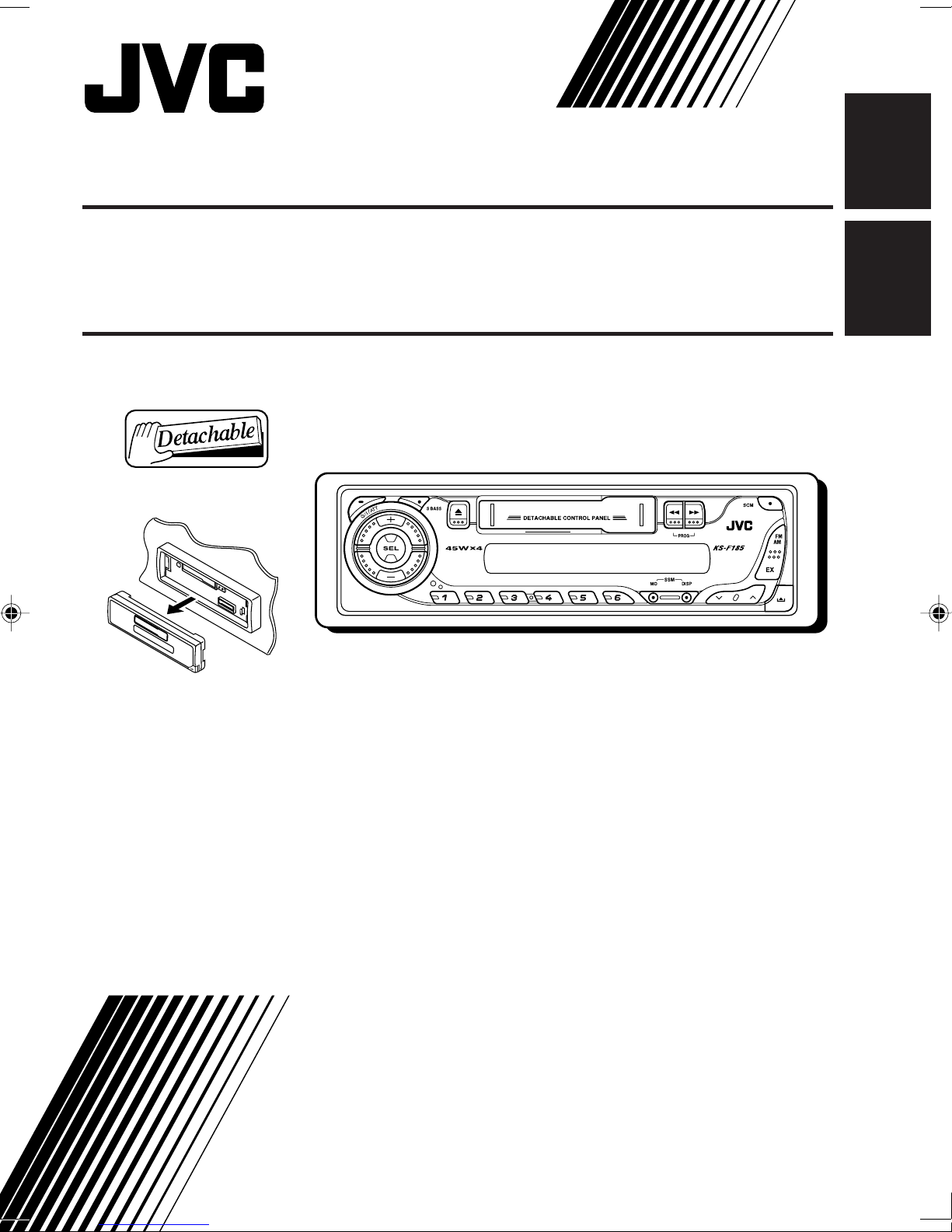
CASSETTE RECEIVER KS-F185
«‘∑¬ÿ‡§√◊ËÕ߇≈Ëπ‡∑ª KS-F185
ENGLISH
‰∑¬
For installation and connections, refer to the separate manual.
°√ÿ≥“¥Ÿ§ŸË¡◊Õ∑’Ë·¬°µË“ßÀ“° „π°“√µ‘¥µ—Èß·≈–°“√‡™◊ËÕ¡µËÕ
INSTRUCTIONS
§”·π–π”
GET0225-001A
[U/UH]
Page 2

Thank you for purchasing a JVC product.
Please read all instructions carefully before operation, to ensure your complete understanding and to
obtain the best possible performance from the unit.
CONTENTS
ENGLISH
How to reset your unit ............................... 2
LOCATION OF THE BUTTONS ............ 3
Control panel ............................................. 3
BASIC OPERATIONS ....................... 4
Turning on the power ................................ 4
Setting the clock ........................................ 5
RADIO OPERATIONS ...................... 6
Listening to the radio ................................. 6
Storing stations in memory ....................... 7
Tuning in to a preset station ...................... 8
Storing your favorite station in to the
one-touch operation button
(EX—extra) ............................................. 8
How to reset your unit
TAPE OPERATIONS ........................ 9
Listening to a cassette .............................. 9
SOUND ADJUSTMENTS ................... 10
Adjusting the sound .................................. 10
Turning on/off the super bass function ...... 10
Selecting preset sound modes .................. 11
Storing your own sound adjustments ........ 11
DETACHING THE C0NTROL PANEL ...... 12
TROUBLESHOOTING ...................... 13
MAINTENANCE ............................. 14
SPECIFICATIONS ........................... 15
While holding SEL (select), press (standby/on/attenuator) button for more than 2 seconds.
This will reset the built-in microcomputer.
(standby/on/attenuator)
SEL (select)
Note:
Your preset adjustments—such as preset channels or sound adjustments—will also be erased.
BEFORE USE
*For safety....
• Do not raise the volume level too much, as this will
block outside sounds, making driving dangerous.
• Stop the car before performing any complicated
operations.
*Temperature inside the car....
If you have parked the car for a long time in hot
or cold weather, wait until the temperature in the
car becomes normal before operating the unit.
2
Page 3
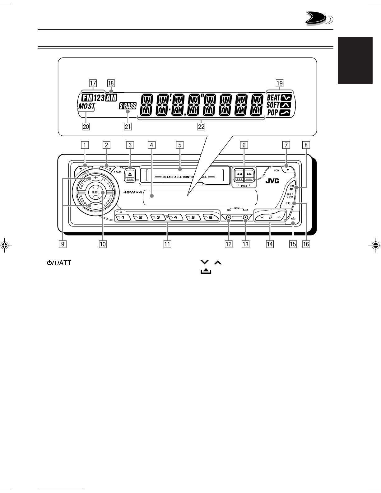
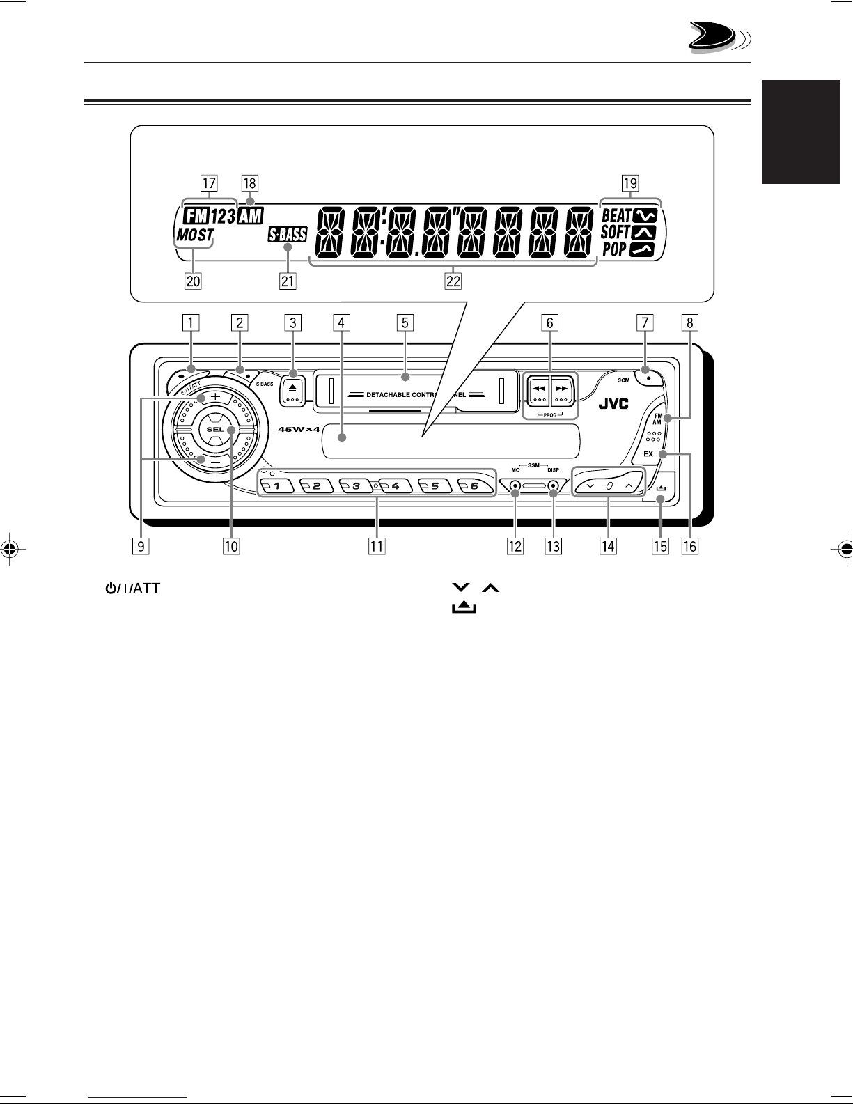
Control panel
Display window
LOCATION OF THE BUTTONS
ENGLISH
1 (standby/on/attenuator) button
2 S BASS (super bass) button
3 0 (eject) button
4 Display window
5 Cassette compartment
6 1/¡ PROG (program) button
7 SCM (sound control memory) button
8 FM AM button
9 +/– buttons
p SEL (select) button
q Number buttons
w MO (monaural) button
• Also functions as SSM buttons when pressed
together with DISP (display) button.
e DISP (display) button
• Also functions as SSM buttons when pressed
together with MO (monaural) button.
r / buttons
t (control panel release) button
y EX (extra) button
Display window
u FM band indicators
FM1, FM2, FM3
i AM band indicator
o Sound mode indicators
BEAT, SOFT, POP
; Tuner reception indicators
MO (monaural), ST (stereo)
a S.BASS (super bass) indicator
s Main display
3
Page 4
ENGLISH
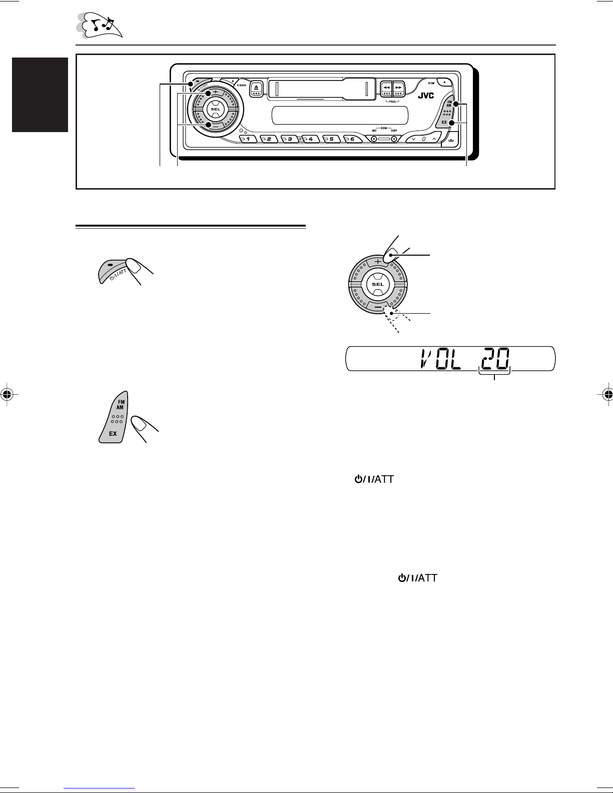
BASIC OPERATIONS
1
3
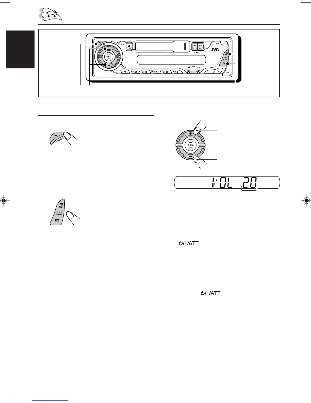
Turning on the power
1
Turn on the power.
Note on One-Touch Operation:
When you select a source in step 2 below, the
power automatically comes on. You do not have
to press this button to turn on the power.
2
Select the source.
To operate the tuner (FM or AM),
see pages 6 – 8.
To operate the EX (extra) button,
see page 8.
To play a tape,
see page 9.
2
3
Adjust the volume.
To increase the volume
To decrease the volume
Volume level appears.
4
Adjust the sound as you want.
(See pages 10 and 11.)
To drop the volume in a moment
Press briefly while listening to any
source. “ATT” starts flashing on the display, and
the volume level will drop in a moment.
To resume the previous volume level, press the
button briefly again.
4
To turn off the power
Press and hold for more than one
second.
“SEE YOU” appears, then the unit turns off.
Page 5
ENGLISH
Frequency
Clock
Play mode (TAPE)
Clock
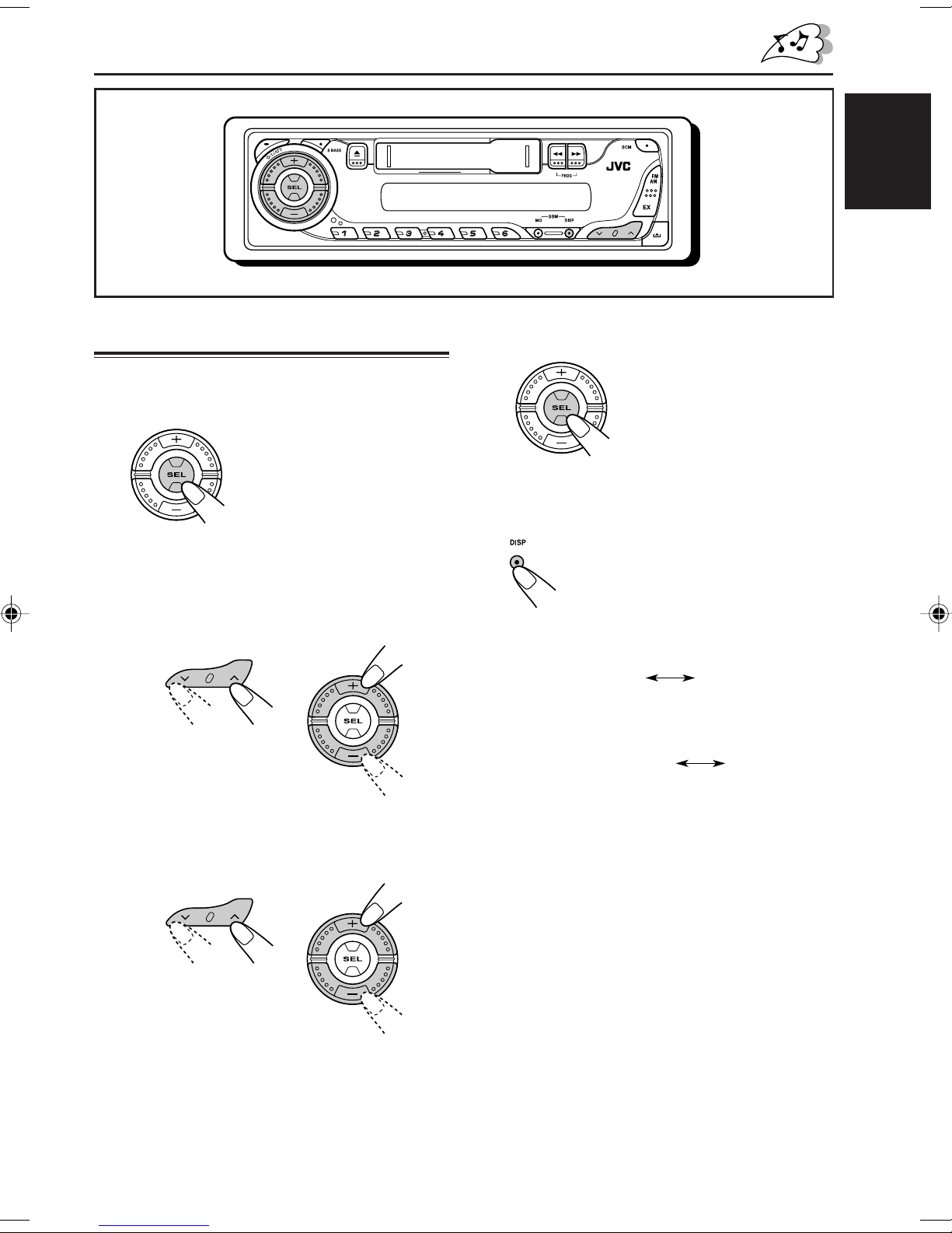
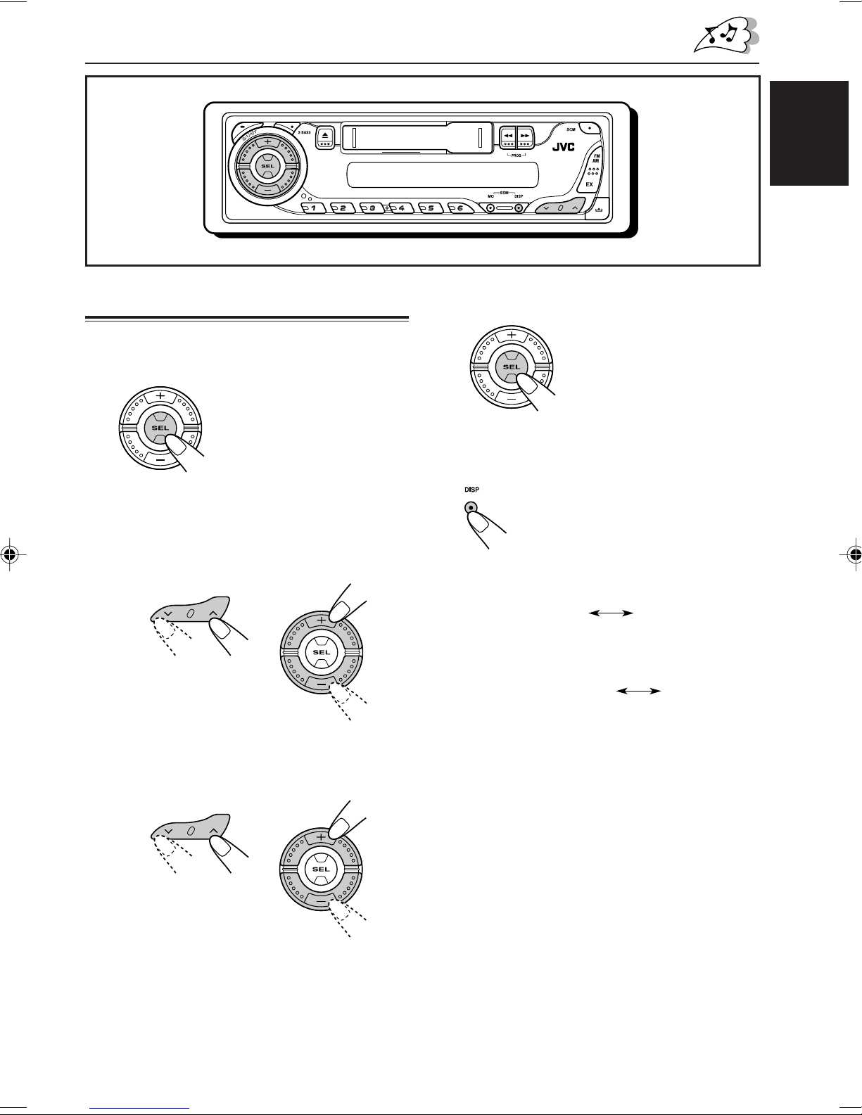
Setting the clock
1
Press and hold SEL (select) for more
than 2 seconds.
“CLOCK H” or “CLOCK M”
appears on the display.
2
Set the hour.
1 Select “CLOCK H” (hour) if not shown on
the display.
2 Adjust the hour.
12
4
Finish the setting.
To check the current clock time or change the
display mode
Press DISP (display) repeatedly.
Each time you press the button,
the display mode changes as
follows:
• During tuner operation:
• During tape operation:
3
Set the minute.
1 Select “CLOCK M” (minute).
2 Adjust the minute.
12
5
Page 6
ENGLISH
RADIO OPERATIONS
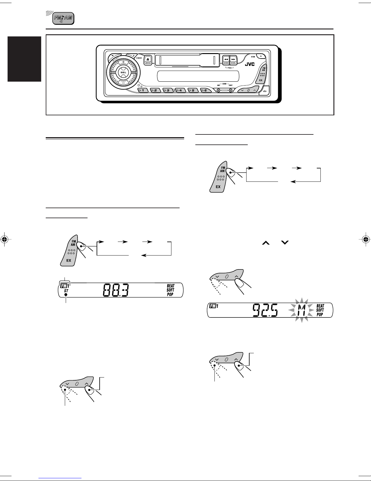
Listening to the radio
You can use either automatic searching or manual
searching to tune in to a particular station.
Note:
When a cassette is in the cassette compartment, you
cannot select the tuner. Be sure to eject the cassette
from the cassette compartment to listen to the radio.
Searching for a station automatically:
Auto search
1
Select the band (FM1 – 3, AM).
FM1
Selected band appears.
FM2
AM
FM3
Searching for a station manually:
Manual search
1
Select the band (FM1 – 3, AM).
FM1
Note:
This receiver has three FM bands (FM1, FM2,
FM3). You can use any one of them to listen to
an FM broadcast.
2
Press and hold or until
“M” (manual) starts flashing on the
display.
FM2
AM
FM3
Lights up when receiving an FM stereo
broadcast with sufficient signal strength.
Note:
This receiver has three FM bands (FM1, FM2,
FM3). You can use any one of them to listen to
an FM broadcast.
2
Start searching for a station.
To search for stations of
higher frequencies
To search for stations of lower frequencies
When a station is received, searching stops.
To stop searching before a station is
received, press the same button you have
pressed for searching.
6
3
Tune in to a station you want while
“M” (manual) is still flashing.
To tune in to stations of
higher frequencies
To tune in to stations of lower frequencies
• If you release your finger from the button,
the manual mode will automatically turns
off after 5 seconds.
• If you hold down the button, the frequency
keeps changing (in 50 kHz intervals for
FM and 9 kHz intervals for AM) until you
release the button.
Page 7
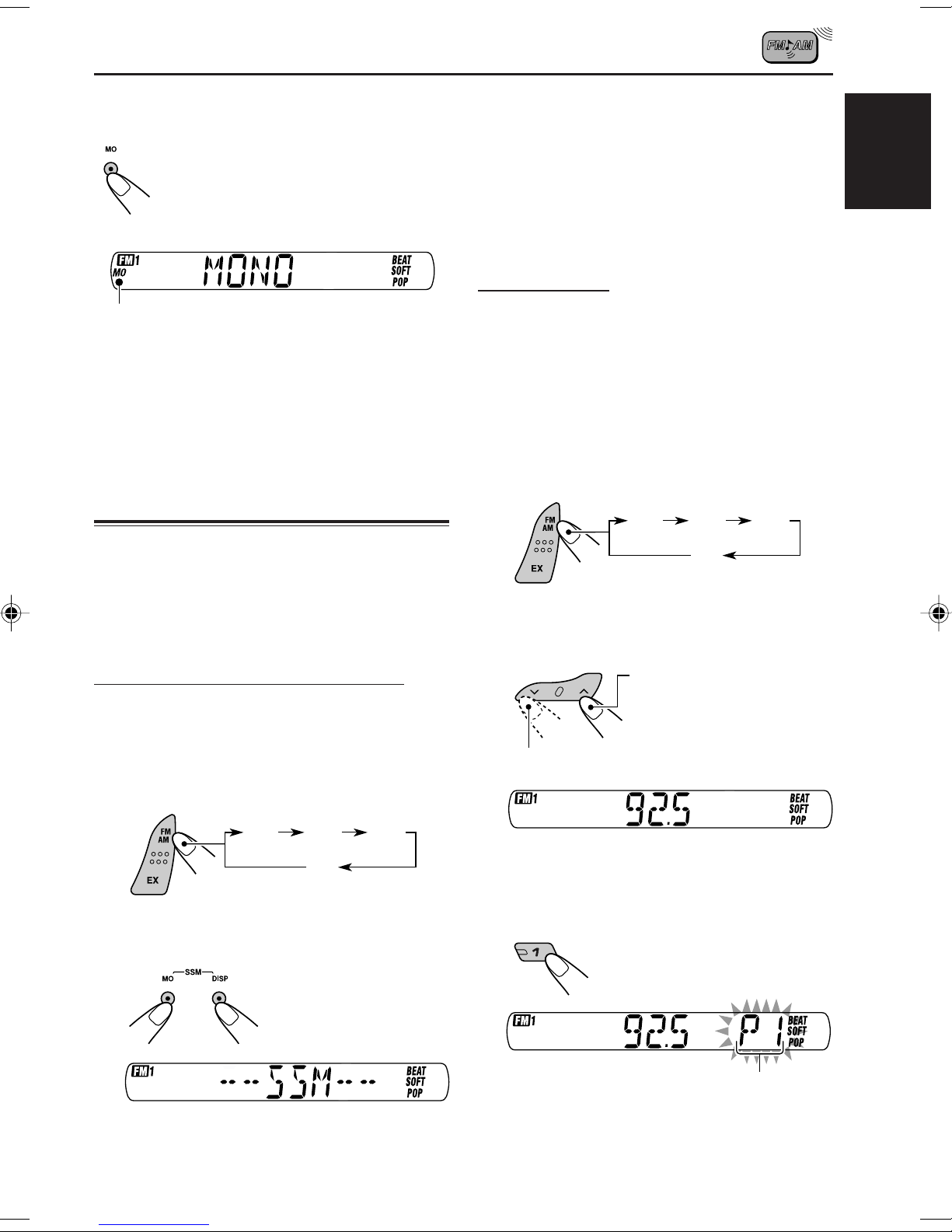
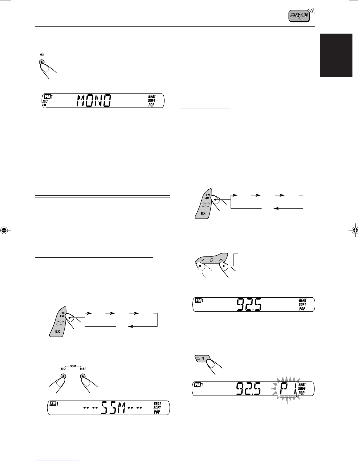
When an FM stereo broadcast is hard to
receive:
Press MO (monaural), while
listening to an FM stereo broadcast.
Each time you press the button, the
MO indicator lights up and goes off
alternately.
Local FM stations with the strongest signals are
searched and stored automatically in the band
number you have selected (FM1, FM2, or FM3).
These stations are preset in the number buttons
—No.1 (lowest frequency) to No.6 (highest
frequency).
When automatic preset is over, the station stored
in number button 1 will be automatically tuned in.
Manual preset
ENGLISH
MO (monaural) indicator
When the MO indicator is lit on the display, the
sound you hear becomes monaural but the
reception will be improved.
To restore the stereo effect, press the same
button again.
Storing stations in memory
You can use one of the following two methods to
store broadcasting stations in memory.
• Automatic preset of FM stations: SSM (Strongstation Sequential Memory)
• Manual preset of both FM and AM stations
FM station automatic preset: SSM
You can preset 6 local FM stations in each FM
band (FM1, FM2, and FM3).
1
Select the FM band (FM1 – 3) you
want to store FM stations into.
You can preset up to 6 stations in each band
(FM1, FM2, FM3, and AM) manually.
Ex.: Storing FM station of 92.5 MHz into the
preset number 1 of the FM1 band.
1
Select the band (FM1 – 3, AM) you
want to store stations into (in this
example, FM1).
FM1
FM2
FM3
AM
2
Tune in to a station (in this example,
of 92.5 MHz).
To tune in to stations of
higher frequencies
To tune in to stations of lower frequencies
FM1
FM2
AM
2
Press and hold both buttons for
more than 2 seconds.
“SSM” appears, then disappears when
automatic preset is over.
FM3
3
Press and hold the number button
(in this example, 1) for more than
2 seconds.
Preset number flashes for a while.
CONTINUED ON THE NEXT PAGE
7
Page 8

4
Repeat the above procedure to store
other stations into other preset
numbers.
ENGLISH
Notes:
• A previously preset station is erased when a new
station is stored in the same preset number.
• Preset stations are erased when the power supply to
the memory circuit is interrupted (for example,
during battery replacement). If this occurs, preset
the stations again.
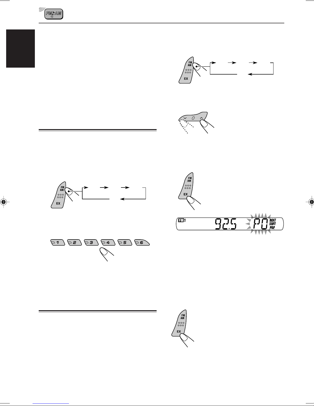
Tuning in to a preset station
You can easily tune in to a preset station.
Remember that you must store stations first. If
you have not stored them yet, see “Storing
stations in memory” on pages 7 and 8.
1
Select the band (FM1 – 3, AM).
1
Select the band (FM1 – 3, AM) you
want to store stations into (in this
example, FM1).
FM1
2
Tune in to a station (in this example,
of 92.5 MHz).
3
Press and hold the button for more
than 2 seconds.
“P0” flashes on the display, showing that the
station has been preset.
FM2
AM
FM3
FM1
2
Select the number (1 – 6) for the
preset station you want.
FM2
AM
FM3
Storing your favorite station in
to the one-touch operation
button (EX—extra)
You can preset an FM or AM station (such as
your favorite station or traffic announcement
station); and recall it by one touch operation even
if the unit is turned off.
Ex.: Storing an FM station of 92.5 MHz in to the
one-touch operation button (EX).
Notes:
• A previously preset station is erased when a new
station is stored in the EX button.
• The preset station is erased when the power supply
to the memory circuit is interrupted (for example,
during battery replacement). If this occurs, preset
the station again.
To tune into the favorite station
The unit automatically turns on
(if it has been off).
Your favorite station is tuned
in—except when the tape is
playing.
• If you press the button again,
the last received station will be
tuned in.
8
Page 9
TAPE OPERATIONS
ENGLISH
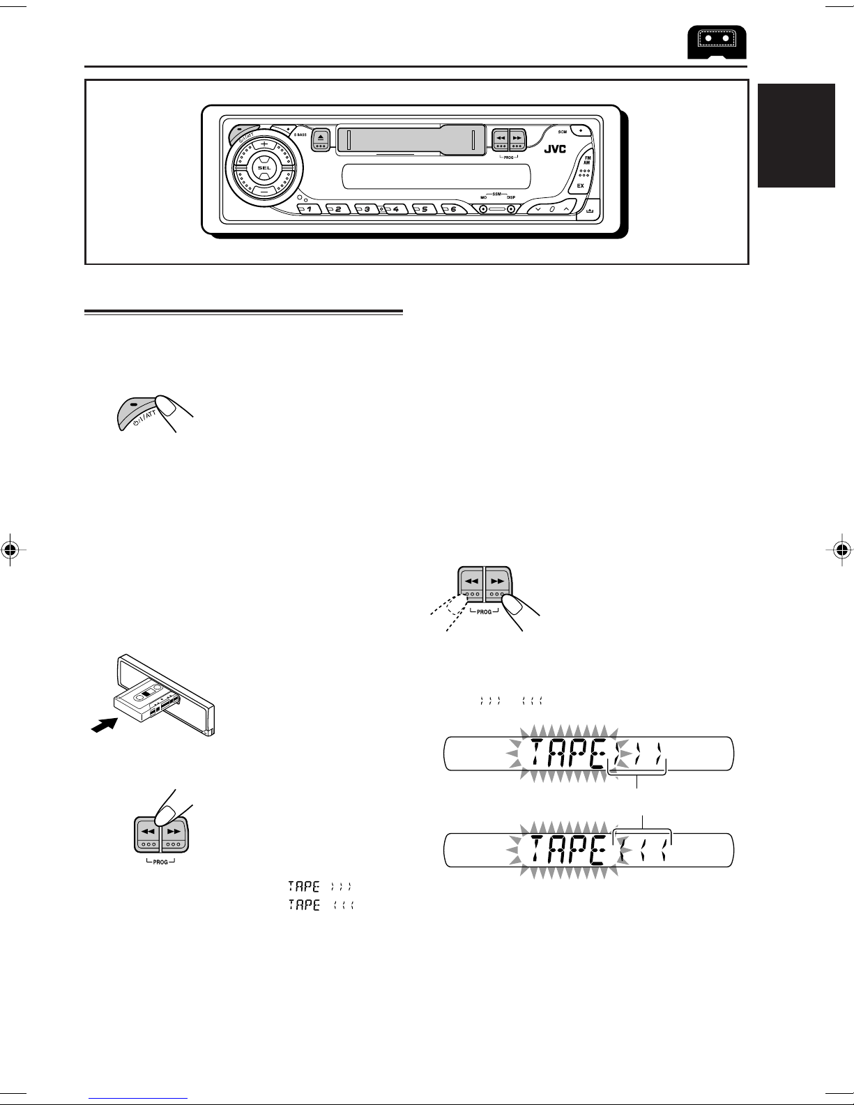
Listening to a cassette
You can play back type I (normal) tapes.
1
Turn on the power.
Note on One-Touch Operation:
When a cassette is already in the cassette
compartment, tape play starts automatically.
However, it is not recommended to leave the
cassette in the compartment when turning off the
power. It may damage the tape head and the
cassette.
2
Insert a cassette into the cassette
compartment.
When one side of the tape
reaches its end during
play, the other side of the
tape automatically starts
playing. (Auto Reverse)
To stop play and eject the cassette
Press 0.
Tape play stops, the cassette automatically
ejects from the cassette compartment. The
source changes to the previously selected one.
• You cannot change the source if the cassette is
still in the cassette compartment.
To change the source, you must eject the
cassette first.
• You can also eject the cassette by pressing 0
while the unit is turned off.
To fast wind a tape
Press in ¡ or 1.
The tape will be wound in the direction of the
arrows ( or ).
3
Select the tape direction.
Press both buttons at the
same time.
Each time you press both
buttons, the tape direction
changes alternately—
forward ( ) and
reverse ( ).
Tape direction
To restart playback, lightly press the other
button which is not pressed in (1 or ¡).
9
Page 10
SOUND ADJUSTMENTS
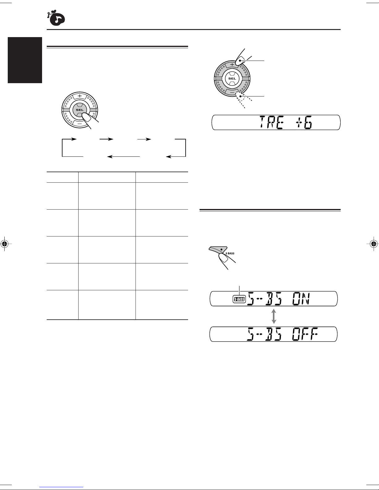
Adjusting the sound
You can adjust the sound characteristics to your
preference.
ENGLISH
1
Select the item you want to adjust.
Each time you press the
button, the adjustable
items change as follows:
BAS
(bass)
VOL
(volume)
Indication To do: Range
BAS Adjust the bass. –6 (min.)
(Bass) |
TRE Adjust the treble. –6 (min.)
(Treble) |
1
FAD*
(Fader) and rear speaker |
BAL Adjust the left L6 (Left only)
(Balance) and right speaker |
2
VOL*
(Volume) |
Adjust the front R6 (Rear only)
balance. F6 (Front only)
balance. R6 (Right only)
Adjust the volume. 00 (min.)
TRE
(treble)
(fader)
BAL
(balance)
+6 (max.)
+6 (max.)
50 (max.)
FAD
2
Adjust the level.
To increase the level
To decrease the level
Ex.: When you select “TRE” (treble)
3
Repeat steps 1 and 2 to adjust the
other items.
Turning on/off the super bass
function
The super bass function allows you to maintain
the richness and fullness of the bass sound
regardless of how low you set the volume.
Each time you press the
button, the function turns on
and off alternately.
S.BASS indicator
*1If you are using a two-speaker system, set the fader
level to “00.”
*2Normally, the + and – buttons work as the volume
control buttons. So you do not have to select “VOL”
to adjust the volume level.
10
Page 11
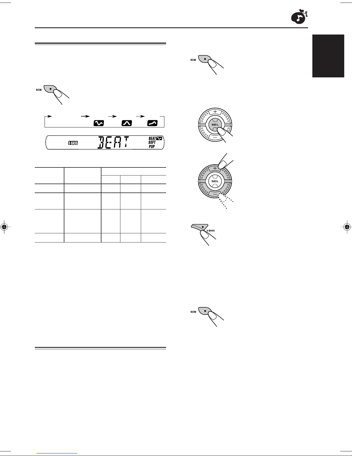
Selecting preset sound modes
You can select a preset sound adjustment
suitable to the music genre.
Select the sound mode you want.
1
Call up the sound mode you want to
adjust.
• See on the left column for
details.
ENGLISH
Each time you press the button,
the sound mode changes as
follows:
BEAT SOFT POPSCM OFF
Ex.: When you select “BEAT”
Indication For: Preset values
BAS TRE S.BASS
SCM OFF (Flat sound) 00 00 OFF
BEAT Rock or +2 00 ON
disco music
SOFT Quiet +1 –3 OFF
background
music
POP Light music +4 +1 OFF
Notes:
• You can adjust each sound mode to your preference,
and store it in memory.
If you want to adjust and store your original sound
mode, see “Storing your own sound adjustments”
below.
• To adjust the bass and treble reinforcement levels or
to turn on/off the super bass function, see page 10.
Storing your own sound
adjustments
2
To adjust the bass or treble level.
1 Select “BAS” (bass) or “TRE” (treble).
2 Adjust the level.
To turn on or off the super bass function.
• See page 10 for details.
3
Repeat step 2 to adjust the other
items.
4
Press and hold SCM until the sound
mode you have selected in step
flashes on the display.
Your adjustment made for
the selected sound mode is
stored in memory.
5
Repeat the same procedure to store
other sound modes.
1
You can adjust the sound modes (BEAT, SOFT,
POP) to your preference and store your own
adjustments in memory.
• There is a time limit in doing the following
procedure. If the setting is canceled before you
finish, start from step 1 again.
To reset to the factory settings, repeat the
same procedure and reassign the preset values
listed in the table on the left column.
11
Page 12
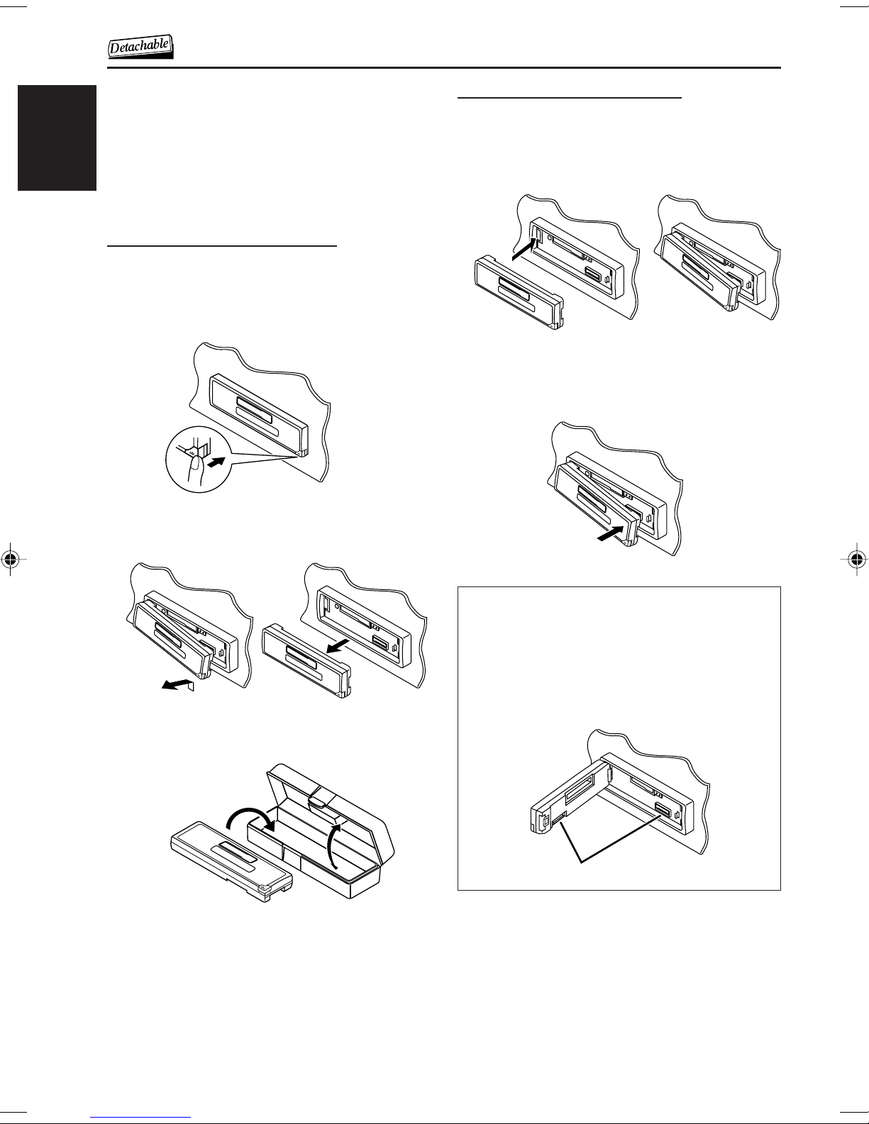
DETACHING THE C0NTROL PANEL
You can detach the control panel when leaving
the car.
When detaching or attaching the control panel,
be careful not to damage the connectors on the
back of the control panel and on the panel
ENGLISH
holder.
Detaching the control panel
Before detaching the control panel, be sure to
turn off the power.
1
Unlock the control panel.
Attaching the control panel
1
Insert the left side of the control
panel into the groove on the panel
holder.
2
Press the right side of the control
panel to fix it to the panel holder.
2
Lift and pull the control panel out of
the unit.
3
Put the detached control panel into
the provided case.
Note on cleaning the connectors:
If you frequently detach the control panel, the
connectors will deteriorate.
To minimize this possibility, periodically wipe the
connectors with a cotton swab or cloth moistened
with alcohol, being careful not to damage the
connectors.
Connectors
12
Page 13
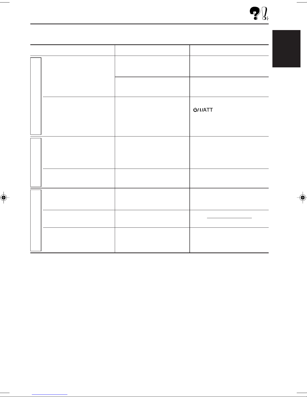
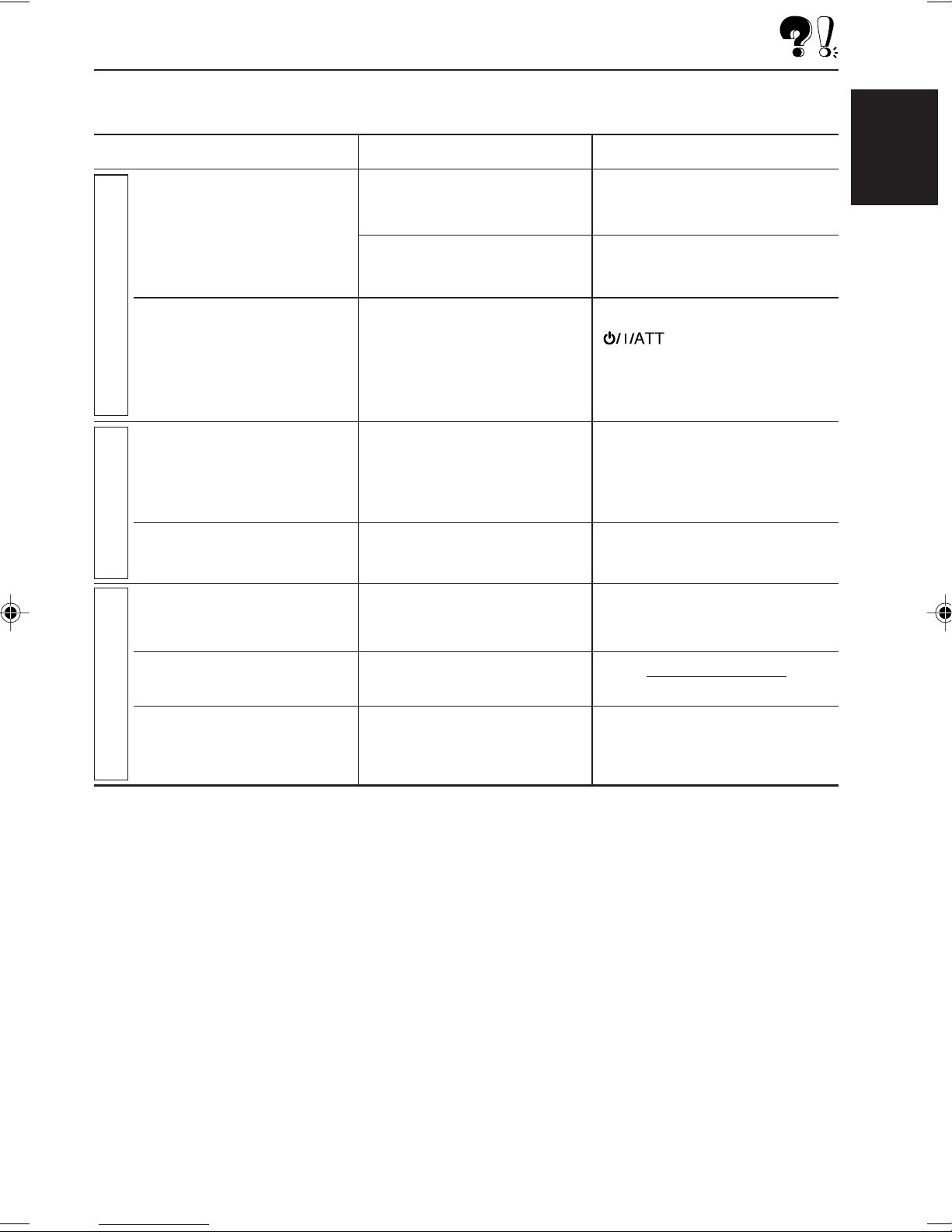
TROUBLESHOOTING
What appears to be trouble is not always serious. Check the following points before calling a service
center.
Symptoms
• Sound cannot be heard
from the speakers.
• This unit does not work at
General
all.
• SSM (Strong-station
Sequential Memory)
automatic preset does not
work.
FM/AM
• Static noise while listening
to the radio.
• A cassette tape cannot be
inserted.
Causes
The volume level is set to the
minimum level.
Connections are incorrect.
The built-in microcomputer
may have functioned
incorrectly due to noise, etc.
Signals are too weak.
The antenna is not connected
firmly.
You have tried to insert a
cassette in the wrong way.
Remedies
Adjust it to the optimum level.
Check the cords and
connections.
While holding SEL, press
for more than 2
seconds to reset the unit. (Your
preset adjustments will also be
erased.) (See page 2.)
Store stations manually.
Connect the antenna firmly.
Insert the cassette with the
exposed tape facing right.
ENGLISH
• Cassette tapes become
hot.
• Tape sound is at very low
Tape Playback
level and sound quality is
degraded.
This is not a malfunction.
The tape head is dirty.
Clean it with a head cleaning
tape.
13
Page 14
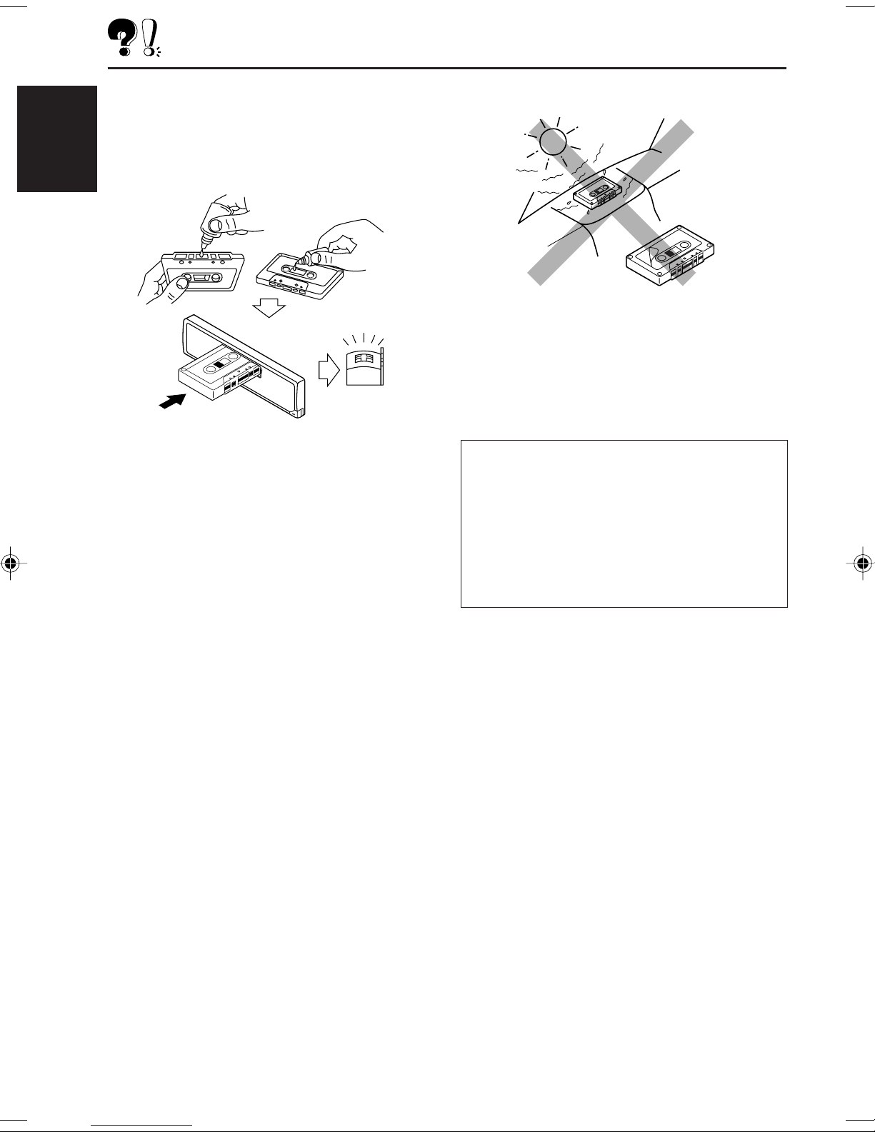
MAINTENANCE
This unit requires very little attention, but you will
be able to extend the life of the unit if you follow
the instructions below.
To clean the head
ENGLISH
• Clean the heads after every 10 hours of use
using a wet-type head cleaning tape (available
at an audio store).
When the head becomes dirty, you may realize
the following symptoms:
– Sound quality is reduced.
– Sound level decreases.
– Sound drops out.
• Do not play dirty or dusty tapes.
• Do not touch the highly-polished head with any
metallic or magnetic tools.
To keep the tape clean
• Always store the cassettes in their storage
cases after use.
• Do not store cassettes in the following places:
– Subject to direct sunlight
– With high humidity
– At extremely hot temperatures
CAUTION:
• Do not play the cassettes with peeling labels;
otherwise, they can damage the unit.
• Tighten tapes to remove slack since loose tape
may become entangled with the mechanism.
• Do not leave a cassette in the cassette
compartment after use, as the tape may become
slack.
14
Page 15
SPECIFICATIONS
AUDIO AMPLIFIER SECTION
Maximum Power Output:
Front: 45 W per channel
Rear: 45 W per channel
Continuous Power Output (RMS):
Front: 17 W per channel into 4 Ω, 40 Hz
to 20 000 Hz at no more than
0.8% total harmonic distortion.
Rear: 17 W per channel into 4 Ω, 40 Hz
to 20 000 Hz at no more than
0.8% total harmonic distortion.
Load Impedance: 4 Ω (4 Ω to 8 Ω allowance)
Tone Control Range:
Bass: ±10 dB at 100 Hz
Treble: ±10 dB at 10 kHz
Frequency Response: 40 Hz to 20 000 Hz
Signal-to-Noise Ratio: 70 dB
Line-Out Level/Impedance:
1.0 V/20 kΩ load (250 nWb/m)
TUNER SECTION
Frequency Range:
FM: 87.5 MHz to 108.0 MHz
AM: 531 kHz to 1 602 kHz
CASSETTE DECK SECTION
Wow & Flutter: 0.15% (WRMS)
Fast-Wind Time: 190 sec. (C-60)
Frequency Response: 50 Hz to 14 000 Hz
(Normal tape)
Signal-to-Noise Ratio: 52 dB
Stereo Separation: 40 dB
GENERAL
Power Requirement:
Operating Voltage: DC 14.4 V
(11 V to 16 V allowance)
Grounding System: Negative ground
Allowable Operating Temperature: 0°C to +40°C
Dimensions (W × H × D):
Installation Size (approx.):
182 mm × 52 mm × 150 mm
Panel Size (approx.):
188 mm × 58 mm × 11 mm
Mass (approx.):
1.3 kg (excluding accessories)
ENGLISH
[FM Tuner]
Usable Sensitivity:
11.3 dBf (1.0 µV/75 Ω)
50 dB Quieting Sensitivity:
16.3 dBf (1.8 µV/75 Ω)
Alternate Channel Selectivity (400 kHz):
65 dB
Frequency Response: 40 Hz to 15 000 Hz
Stereo Separation: 35 dB
Capture Ratio: 2.0 dB
[AM Tuner]
Sensitivity: 20 µV
Selectivity: 35 dB
Having TROUBLE with operation?
Please reset your unit
Design and specifications are subject to change
without notice.
Refer to page of How to reset your unit
15
Page 16

EN, TH 0604DTSMDTJEIN
© 2004 VICTOR COMPANY OF JAPAN, LIMITED
Page 17

CASSETTE RECEIVER KS-F185/KS-F185S/KS-F185G
ENGLISH
RADIO KASET KS-F185/KS-F185S/KS-F185G
INDONESIA
FRANÇAIS
For installation and connections, refer to the separate manual.
Untuk instalasi dan penyambungan, lihat buku pedoman terpisah.
INSTRUCTIONS
BUKU PETUNJUK
GET0225-003A
[UN]
Page 18

Thank you for purchasing a JVC product.
Please read all instructions carefully before operation, to ensure your complete understanding and to
obtain the best possible performance from the unit.
CONTENTS
ENGLISH
How to reset your unit ............................... 2
LOCATION OF THE BUTTONS ............ 3
Control panel ............................................. 3
BASIC OPERATIONS ....................... 4
Turning on the power ................................ 4
Setting the clock ........................................ 5
RADIO OPERATIONS ...................... 6
Listening to the radio ................................. 6
Storing stations in memory ....................... 7
Tuning in to a preset station ...................... 8
Storing your favorite station in to the
one-touch operation button
(EX—extra) ............................................. 8
How to reset your unit
TAPE OPERATIONS ........................ 9
Listening to a cassette .............................. 9
SOUND ADJUSTMENTS ................... 10
Adjusting the sound .................................. 10
Turning on/off the super bass function ...... 10
Selecting preset sound modes .................. 11
Storing your own sound adjustments ........ 11
DETACHING THE C0NTROL PANEL ...... 12
TROUBLESHOOTING ...................... 13
MAINTENANCE ............................. 14
SPECIFICATIONS ........................... 15
While holding SEL (select), press (standby/on/attenuator) button for more than 2 seconds.
This will reset the built-in microcomputer.
(standby/on/attenuator)
SEL (select)
Note:
Your preset adjustments—such as preset channels or sound adjustments—will also be erased.
BEFORE USE
*For safety....
• Do not raise the volume level too much, as this will
block outside sounds, making driving dangerous.
• Stop the car before performing any complicated
operations.
*Temperature inside the car....
If you have parked the car for a long time in hot
or cold weather, wait until the temperature in the
car becomes normal before operating the unit.
2
Page 19
Control panel
Display window
LOCATION OF THE BUTTONS
ENGLISH
1 (standby/on/attenuator) button
2 S BASS (super bass) button
3 0 (eject) button
4 Display window
5 Cassette compartment
6 1/¡ PROG (program) button
7 SCM (sound control memory) button
8 FM AM button
9 +/– buttons
p SEL (select) button
q Number buttons
w MO (monaural) button
• Also functions as SSM buttons when pressed
together with DISP (display) button.
e DISP (display) button
• Also functions as SSM buttons when pressed
together with MO (monaural) button.
r / buttons
t (control panel release) button
y EX (extra) button
Display window
u FM band indicators
FM1, FM2, FM3
i AM band indicator
o Sound mode indicators
BEAT, SOFT, POP
; Tuner reception indicators
MO (monaural), ST (stereo)
a S.BASS (super bass) indicator
s Main display
3
Page 20
ENGLISH
BASIC OPERATIONS
1
3
Turning on the power
1
Turn on the power.
Note on One-Touch Operation:
When you select a source in step 2 below, the
power automatically comes on. You do not have
to press this button to turn on the power.
2
Select the source.
To operate the tuner (FM or AM),
see pages 6 – 8.
To operate the EX (extra) button,
see page 8.
To play a tape,
see page 9.
2
3
Adjust the volume.
To increase the volume
To decrease the volume
Volume level appears.
4
Adjust the sound as you want.
(See pages 10 and 11.)
To drop the volume in a moment
Press briefly while listening to any
source. “ATT” starts flashing on the display, and
the volume level will drop in a moment.
To resume the previous volume level, press the
button briefly again.
4
To turn off the power
Press and hold for more than one
second.
“SEE YOU” appears, then the unit turns off.
Page 21
ENGLISH
Frequency
Clock
Play mode (TAPE)
Clock
Setting the clock
1
Press and hold SEL (select) for more
than 2 seconds.
“CLOCK H” or “CLOCK M”
appears on the display.
2
Set the hour.
1 Select “CLOCK H” (hour) if not shown on
the display.
2 Adjust the hour.
12
4
Finish the setting.
To check the current clock time or change the
display mode
Press DISP (display) repeatedly.
Each time you press the button,
the display mode changes as
follows:
• During tuner operation:
• During tape operation:
3
Set the minute.
1 Select “CLOCK M” (minute).
2 Adjust the minute.
12
5
Page 22

ENGLISH
RADIO OPERATIONS
Listening to the radio
You can use either automatic searching or manual
searching to tune in to a particular station.
Note:
When a cassette is in the cassette compartment, you
cannot select the tuner. Be sure to eject the cassette
from the cassette compartment to listen to the radio.
Searching for a station automatically:
Auto search
1
Select the band (FM1 – 3, AM).
FM1
Selected band appears.
FM2
AM
FM3
Searching for a station manually:
Manual search
1
Select the band (FM1 – 3, AM).
FM1
Note:
This receiver has three FM bands (FM1, FM2,
FM3). You can use any one of them to listen to
an FM broadcast.
2
Press and hold or until
“M” (manual) starts flashing on the
display.
FM2
AM
FM3
Lights up when receiving an FM stereo
broadcast with sufficient signal strength.
Note:
This receiver has three FM bands (FM1, FM2,
FM3). You can use any one of them to listen to
an FM broadcast.
2
Start searching for a station.
To search for stations of
higher frequencies
To search for stations of lower frequencies
When a station is received, searching stops.
To stop searching before a station is
received, press the same button you have
pressed for searching.
6
3
Tune in to a station you want while
“M” (manual) is still flashing.
To tune in to stations of
higher frequencies
To tune in to stations of lower frequencies
• If you release your finger from the button,
the manual mode will automatically turns
off after 5 seconds.
• If you hold down the button, the frequency
keeps changing (in 50 kHz intervals for
FM and 9 kHz intervals for AM) until you
release the button.
Page 23
When an FM stereo broadcast is hard to
receive:
Press MO (monaural), while
listening to an FM stereo broadcast.
Each time you press the button, the
MO indicator lights up and goes off
alternately.
Local FM stations with the strongest signals are
searched and stored automatically in the band
number you have selected (FM1, FM2, or FM3).
These stations are preset in the number buttons
—No.1 (lowest frequency) to No.6 (highest
frequency).
When automatic preset is over, the station stored
in number button 1 will be automatically tuned in.
Manual preset
ENGLISH
MO (monaural) indicator
When the MO indicator is lit on the display, the
sound you hear becomes monaural but the
reception will be improved.
To restore the stereo effect, press the same
button again.
Storing stations in memory
You can use one of the following two methods to
store broadcasting stations in memory.
• Automatic preset of FM stations: SSM (Strongstation Sequential Memory)
• Manual preset of both FM and AM stations
FM station automatic preset: SSM
You can preset 6 local FM stations in each FM
band (FM1, FM2, and FM3).
You can preset up to 6 stations in each band
(FM1, FM2, FM3, and AM) manually.
Ex.: Storing FM station of 92.5 MHz into the
preset number 1 of the FM1 band.
1
Select the band (FM1 – 3, AM) you
want to store stations into (in this
example, FM1).
FM1
FM2
FM3
AM
2
Tune in to a station (in this example,
of 92.5 MHz).
To tune in to stations of
higher frequencies
1
Select the FM band (FM1 – 3) you
want to store FM stations into.
FM1
FM2
AM
2
Press and hold both buttons for
more than 2 seconds.
“SSM” appears, then disappears when
automatic preset is over.
FM3
To tune in to stations of lower frequencies
3
Press and hold the number button
(in this example, 1) for more than
2 seconds.
Preset number flashes for a while.
CONTINUED ON THE NEXT PAGE
7
Page 24
4
Repeat the above procedure to store
other stations into other preset
numbers.
ENGLISH
Notes:
• A previously preset station is erased when a new
station is stored in the same preset number.
• Preset stations are erased when the power supply to
the memory circuit is interrupted (for example,
during battery replacement). If this occurs, preset
the stations again.
Tuning in to a preset station
You can easily tune in to a preset station.
Remember that you must store stations first. If
you have not stored them yet, see “Storing
stations in memory” on pages 7 and 8.
1
Select the band (FM1 – 3, AM).
1
Select the band (FM1 – 3, AM) you
want to store stations into (in this
example, FM1).
FM1
2
Tune in to a station (in this example,
of 92.5 MHz).
3
Press and hold the button for more
than 2 seconds.
“P0” flashes on the display, showing that the
station has been preset.
FM2
AM
FM3
FM1
2
Select the number (1 – 6) for the
preset station you want.
FM2
AM
FM3
Storing your favorite station in
to the one-touch operation
button (EX—extra)
You can preset an FM or AM station (such as
your favorite station or traffic announcement
station); and recall it by one touch operation even
if the unit is turned off.
Ex.: Storing an FM station of 92.5 MHz in to the
one-touch operation button (EX).
Notes:
• A previously preset station is erased when a new
station is stored in the EX button.
• The preset station is erased when the power supply
to the memory circuit is interrupted (for example,
during battery replacement). If this occurs, preset
the station again.
To tune into the favorite station
The unit automatically turns on
(if it has been off).
Your favorite station is tuned
in—except when the tape is
playing.
• If you press the button again,
the last received station will be
tuned in.
8
Page 25

TAPE OPERATIONS
ENGLISH
Listening to a cassette
You can play back type I (normal) tapes.
1
Turn on the power.
Note on One-Touch Operation:
When a cassette is already in the cassette
compartment, tape play starts automatically.
However, it is not recommended to leave the
cassette in the compartment when turning off the
power. It may damage the tape head and the
cassette.
2
Insert a cassette into the cassette
compartment.
When one side of the tape
reaches its end during
play, the other side of the
tape automatically starts
playing. (Auto Reverse)
To stop play and eject the cassette
Press 0.
Tape play stops, the cassette automatically
ejects from the cassette compartment. The
source changes to the previously selected one.
• You cannot change the source if the cassette is
still in the cassette compartment.
To change the source, you must eject the
cassette first.
• You can also eject the cassette by pressing 0
while the unit is turned off.
To fast wind a tape
Press in ¡ or 1.
The tape will be wound in the direction of the
arrows ( or ).
3
Select the tape direction.
Press both buttons at the
same time.
Each time you press both
buttons, the tape direction
changes alternately—
forward ( ) and
reverse ( ).
Tape direction
To restart playback, lightly press the other
button which is not pressed in (1 or ¡).
9
Page 26

SOUND ADJUSTMENTS
Adjusting the sound
You can adjust the sound characteristics to your
preference.
ENGLISH
1
Select the item you want to adjust.
Each time you press the
button, the adjustable
items change as follows:
BAS
(bass)
VOL
(volume)
Indication To do: Range
BAS Adjust the bass. –6 (min.)
(Bass) |
TRE Adjust the treble. –6 (min.)
(Treble) |
1
FAD*
(Fader) and rear speaker |
BAL Adjust the left L6 (Left only)
(Balance) and right speaker |
2
VOL*
(Volume) |
Adjust the front R6 (Rear only)
balance. F6 (Front only)
balance. R6 (Right only)
Adjust the volume. 00 (min.)
TRE
(treble)
(fader)
BAL
(balance)
+6 (max.)
+6 (max.)
50 (max.)
FAD
2
Adjust the level.
To increase the level
To decrease the level
Ex.: When you select “TRE” (treble)
3
Repeat steps 1 and 2 to adjust the
other items.
Turning on/off the super bass
function
The super bass function allows you to maintain
the richness and fullness of the bass sound
regardless of how low you set the volume.
Each time you press the
button, the function turns on
and off alternately.
S.BASS indicator
*1If you are using a two-speaker system, set the fader
level to “00.”
*2Normally, the + and – buttons work as the volume
control buttons. So you do not have to select “VOL”
to adjust the volume level.
10
Page 27

Selecting preset sound modes
You can select a preset sound adjustment
suitable to the music genre.
Select the sound mode you want.
1
Call up the sound mode you want to
adjust.
• See on the left column for
details.
ENGLISH
Each time you press the button,
the sound mode changes as
follows:
BEAT SOFT POPSCM OFF
Ex.: When you select “BEAT”
Indication For: Preset values
BAS TRE S.BASS
SCM OFF (Flat sound) 00 00 OFF
BEAT Rock or +2 00 ON
disco music
SOFT Quiet +1 –3 OFF
background
music
POP Light music +4 +1 OFF
2
To adjust the bass or treble level.
1 Select “BAS” (bass) or “TRE” (treble).
2 Adjust the level.
To turn on or off the super bass function.
• See page 10 for details.
Notes:
• You can adjust each sound mode to your preference,
and store it in memory.
If you want to adjust and store your original sound
mode, see “Storing your own sound adjustments”
below.
• To adjust the bass and treble reinforcement levels or
to turn on/off the super bass function, see page 10.
Storing your own sound
adjustments
You can adjust the sound modes (BEAT, SOFT,
POP) to your preference and store your own
adjustments in memory.
• There is a time limit in doing the following
procedure. If the setting is canceled before you
finish, start from step 1 again.
3
Repeat step 2 to adjust the other
items.
4
Press and hold SCM until the sound
mode you have selected in step
1
flashes on the display.
Your adjustment made for
the selected sound mode is
stored in memory.
5
Repeat the same procedure to store
other sound modes.
To reset to the factory settings, repeat the
same procedure and reassign the preset values
listed in the table on the left column.
11
Page 28

DETACHING THE C0NTROL PANEL
You can detach the control panel when leaving
the car.
When detaching or attaching the control panel,
be careful not to damage the connectors on the
back of the control panel and on the panel
ENGLISH
holder.
Detaching the control panel
Before detaching the control panel, be sure to
turn off the power.
1
Unlock the control panel.
Attaching the control panel
1
Insert the left side of the control
panel into the groove on the panel
holder.
2
Press the right side of the control
panel to fix it to the panel holder.
2
Lift and pull the control panel out of
the unit.
3
Put the detached control panel into
the provided case.
Note on cleaning the connectors:
If you frequently detach the control panel, the
connectors will deteriorate.
To minimize this possibility, periodically wipe the
connectors with a cotton swab or cloth moistened
with alcohol, being careful not to damage the
connectors.
Connectors
12
Page 29
TROUBLESHOOTING
What appears to be trouble is not always serious. Check the following points before calling a service
center.
Symptoms
• Sound cannot be heard
from the speakers.
• This unit does not work at
General
all.
• SSM (Strong-station
Sequential Memory)
automatic preset does not
work.
FM/AM
• Static noise while listening
to the radio.
Causes
The volume level is set to the
minimum level.
Connections are incorrect.
The built-in microcomputer
may have functioned
incorrectly due to noise, etc.
Signals are too weak.
The antenna is not connected
firmly.
Remedies
Adjust it to the optimum level.
Check the cords and
connections.
While holding SEL, press
for more than 2
seconds to reset the unit. (Your
preset adjustments will also be
erased.) (See page 2.)
Store stations manually.
Connect the antenna firmly.
ENGLISH
• A cassette tape cannot be
inserted.
• Cassette tapes become
hot.
• Tape sound is at very low
Tape Playback
level and sound quality is
degraded.
You have tried to insert a
cassette in the wrong way.
This is not a malfunction.
The tape head is dirty.
Insert the cassette with the
exposed tape facing right.
Clean it with a head cleaning
tape.
13
Page 30

MAINTENANCE
This unit requires very little attention, but you will
be able to extend the life of the unit if you follow
the instructions below.
To clean the head
ENGLISH
• Clean the heads after every 10 hours of use
using a wet-type head cleaning tape (available
at an audio store).
When the head becomes dirty, you may realize
the following symptoms:
– Sound quality is reduced.
– Sound level decreases.
– Sound drops out.
• Do not play dirty or dusty tapes.
• Do not touch the highly-polished head with any
metallic or magnetic tools.
To keep the tape clean
• Always store the cassettes in their storage
cases after use.
• Do not store cassettes in the following places:
– Subject to direct sunlight
– With high humidity
– At extremely hot temperatures
CAUTION:
• Do not play the cassettes with peeling labels;
otherwise, they can damage the unit.
• Tighten tapes to remove slack since loose tape
may become entangled with the mechanism.
• Do not leave a cassette in the cassette
compartment after use, as the tape may become
slack.
14
Page 31

SPECIFICATIONS
AUDIO AMPLIFIER SECTION
Maximum Power Output:
Front: 45 W per channel
Rear: 45 W per channel
Continuous Power Output (RMS):
Front: 17 W per channel into 4 Ω, 40 Hz
to 20 000 Hz at no more than
0.8% total harmonic distortion.
Rear: 17 W per channel into 4 Ω, 40 Hz
to 20 000 Hz at no more than
0.8% total harmonic distortion.
Load Impedance: 4 Ω (4 Ω to 8 Ω allowance)
Tone Control Range:
Bass: ±10 dB at 100 Hz
Treble: ±10 dB at 10 kHz
Frequency Response: 40 Hz to 20 000 Hz
Signal-to-Noise Ratio: 70 dB
Line-Out Level/Impedance:
1.0 V/20 kΩ load (250 nWb/m)
TUNER SECTION
Frequency Range:
FM: 87.5 MHz to 108.0 MHz
AM: 531 kHz to 1 602 kHz
CASSETTE DECK SECTION
Wow & Flutter: 0.15% (WRMS)
Fast-Wind Time: 190 sec. (C-60)
Frequency Response: 50 Hz to 14 000 Hz
(Normal tape)
Signal-to-Noise Ratio: 52 dB
Stereo Separation: 40 dB
GENERAL
Power Requirement:
Operating Voltage: DC 14.4 V
(11 V to 16 V allowance)
Grounding System: Negative ground
Allowable Operating Temperature: 0°C to +40°C
Dimensions (W × H × D):
Installation Size (approx.):
182 mm × 52 mm × 150 mm
Panel Size (approx.):
188 mm × 58 mm × 11 mm
Mass (approx.):
1.3 kg (excluding accessories)
ENGLISH
[FM Tuner]
Usable Sensitivity:
11.3 dBf (1.0 µV/75 Ω)
50 dB Quieting Sensitivity:
16.3 dBf (1.8 µV/75 Ω)
Alternate Channel Selectivity (400 kHz):
65 dB
Frequency Response: 40 Hz to 15 000 Hz
Stereo Separation: 35 dB
Capture Ratio: 2.0 dB
[AM Tuner]
Sensitivity: 20 µV
Selectivity: 35 dB
Having TROUBLE with operation?
Please reset your unit
Design and specifications are subject to change
without notice.
Refer to page of How to reset your unit
15
Page 32

EN, IN 0604DTSMDTJEIN
© 2004 VICTOR COMPANY OF JAPAN, LIMITED
Page 33
KS-FX385/KS-F185
Installation/Connection Manual
°“√µ‘¥µ—Èß/§ŸË¡◊Õ°“√µ‘¥µ—Èß
0604DTSMDTJEIN
EN, TH
GET0225-004A
[U/UH]
J
Handles
§—π∫—ߧ—∫
F
Washer (ø5)
ª√–‡°Áπ«ß·À«π (ø5)
G
Lock nut (M5)
πÕµ≈ÁÕ§ (M5)
H
Mounting bolt (M5 x 20 mm)
≈—°µ‘¥ (M5 x 20 ¡‘≈≈‘‡¡µ√)
I
Rubber cushion
¬“ß°—π°√–·∑°
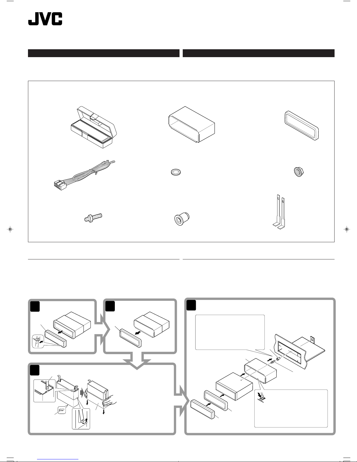
Parts list for installation and connection
The following parts are provided for this unit.
After checking them, please set them correctly.
A / B
Hard case/Control panel
≈—ß∫√√®ÿ/ÀπÈ“ª—¥
C
Sleeve
ª≈Õ°ÀÿÈ¡
D
Trim plate
·ºËπ‚≈À–¢Õ∫·µËß
E
Power cord
“¬‡§‡∫‘≈°”≈—ß
INSTALLATION (IN-DASH MOUNTING)
The following illustration shows a typical installation. If you have any questions or require
information regarding installation kits, consult your JVC car audio dealer or a company supplying
kits.
• If you are not sure how to install this unit correctly, have it installed by a qualified technician.
ENGLISH
This unit is designed to operate on 12 V DC, NEGATIVE ground electrical systems. If your
vehicle does not have this system, a voltage inverter is required, which can be purchased at
JVC car audio dealers.
1
‰∑¬™ÿ¥ª√–°Õ∫π’ȉ¥È√—∫°“√ÕÕ°·∫∫¡“‡æ◊ËÕ„™Èß“π°—∫√–∫∫
4
3
2
1
B
53 mm
184 mm
Ÿ
~
!
@
¤
D
I
H
C
D
B
J
C
*1
⁄
*1When you stand the unit, be
careful not to damage the fuse
on the rear.
*
1
‡¡◊ËÕ§ÿ≥µ—Èß™ÿ¥ª√–°Õ∫¢÷Èπ √–«—
ßլ˓∑”„ÀÈø‘«Ï∫√‘‡«≥Ë«π∑È“¬‡’¬À“¬
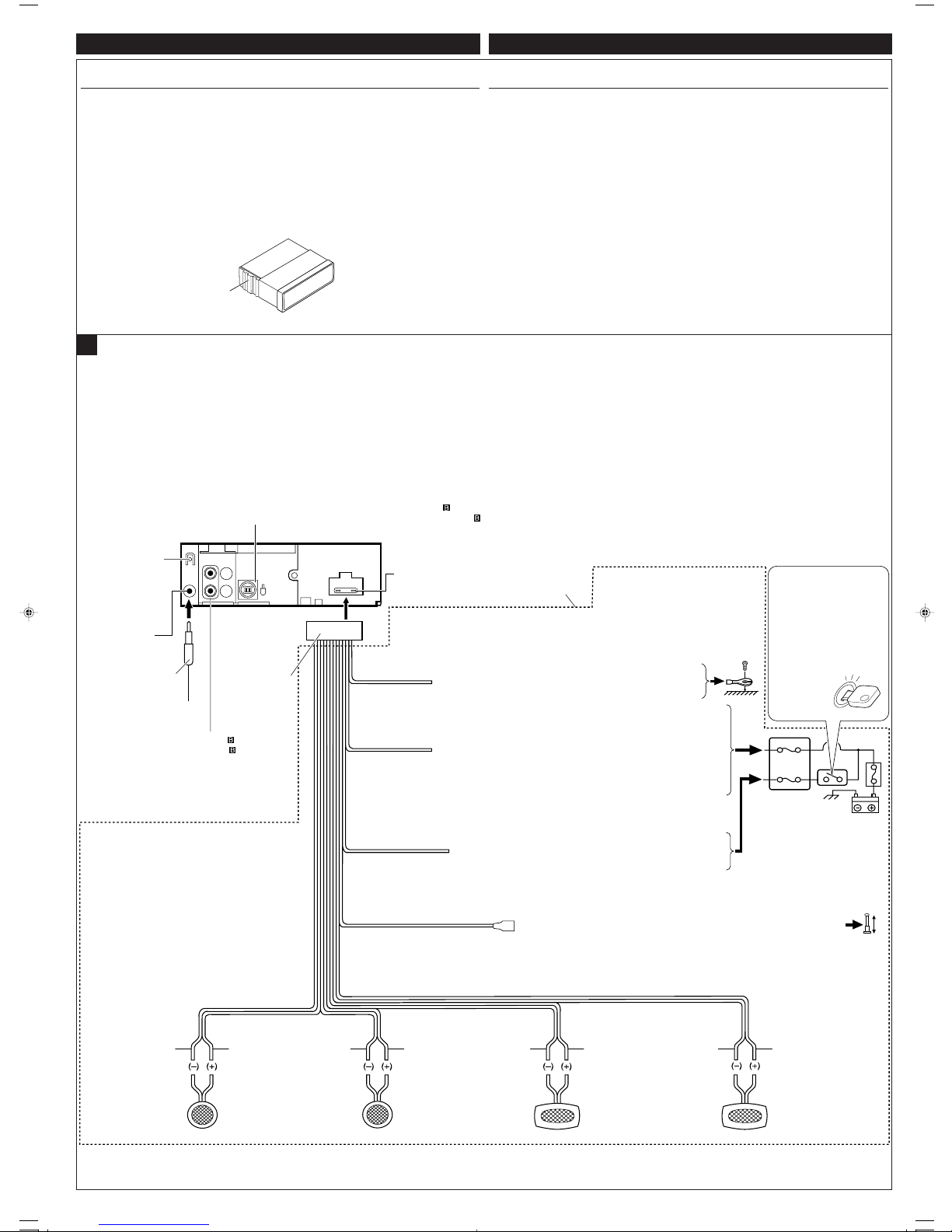
Do the required electrical connections.
µËÕ“¬‰øµ“¡∑’Ë°”À𥉫È∑—ÈßÀ¡¥
Bend the appropriate tabs to hold
the sleeve firmly in place.
ßÕ·ºËπ‡æ◊ËÕ¬÷¥ª≈Õ°„ÀȵËÕ°—π‡¢È“∑’Ë
™ÿ¥ª√–°Õ∫π’ȉ¥È√—∫°“√ÕÕ°·∫∫¡“‡æ◊ËÕ„™Èß“π°—∫√–∫∫ °√–·‰øøÈ““¬¥‘π¢—È«≈∫°√–·µ√ß
12 ‚«≈∑Ï
À“°√∂¬πµÏ¢Õߧÿ≥‰¡Ë‰¥È „™È√–∫∫π’È µÈÕß„™È‡§√◊ËÕß·ª≈ß°√–·‰ø™Ë«¬ ´÷Ëß“¡“√∂À“´◊ÈÕ‰¥È®“°√È“π¢“¬‡§√◊ËÕ߇’¬ß√∂¬πµÏ JVC
√“¬°“√Ë«πª√–°Õ∫”À√—∫µ‘¥µ—Èß·≈–‡™◊ËÕ¡µËÕ°—π
Ë«πª√–°Õ∫µËÕ‰ªπ’È„ÀÈ¡“°—∫™ÿ¥ª√–°Õ∫π’È À≈—ß®“°µ√«®Õ∫·≈È« ª√—∫µ—È߇§√◊ËÕß„ÀÈ∂Ÿ°µÈÕß
°“√µ‘¥µ—Èß (°“√ª√–°Õ∫·ºßÀπÈ“ª—∑¡Ï‡¢È“)
¿“æµ—«Õ¬Ë“ßµËÕ‰ªπ’È·¥ß∂÷ß°“√µ‘¥µ—Èß·∫∫∑—Ë«‰ª À“°§ÿ≥¡’ª—≠À“À√◊ÕµÈÕß°“√¢ÈÕ¡Ÿ≈‡°’ˬ«°—∫™ÿ¥µ‘¥µ—Èß °√ÿ≥“ª√÷°…“°—
∫ºŸÈ¢“¬‡§√◊ËÕ߇’¬ß√∂¬πµÏ JVC ¢Õß∑Ë“πÀ√◊Õ∫√‘…—
• ™ÿ¥ª√–°Õ∫ ∂È“§ÿ≥‰¡Ë·πË„®«Ë“µ‘¥µ—Èß™ÿ¥ª√–°Õ∫π’È∂Ÿ°µÈÕßÀ√◊Õ‰¡Ë „ÀÈÀ“™Ë“ߺŸÈ‡™’ˬ«™“≠‡ªÁπºŸÈµ‘¥µ—Èß
Page 34

When installing the unit without using the sleeve / ‡¡◊ËÕµ‘¥µ—Èß™ÿ¥ª√–°Õ∫‚¥¬‰¡Ë„™Èª≈Õ°ÀÿÈ¡
In a Toyota for example, first remove the car radio and install the unit in its place.
µ—«Õ¬Ë“߇™Ëπ „π√∂¬πµÏ‚µ‚¬µÈ“ „ÀÈ∂Õ¥«‘∑¬ÿµ‘¥√∂¬πµÏÕÕ°°ËÕπ·≈–µ‘¥µ—Èß™ÿ¥ª√–°Õ∫π’ȇ¢È“‰ª·∑π
Note : When installing the unit on the mounting bracket, make sure to use the 8 mm-long screws. If
longer screws are used, they could damage the unit.
À¡“¬‡Àµ : ‡¡◊ËÕµ‘¥µ—Èß™ÿ¥ª√–°Õ∫≈ß„π·∑Ëπ√Õß√—∫‰«È „ÀÈ„™È°√Ÿ¬“«¢π“¥ 8 ¡‘≈≈‘‡¡µ√ ∂È“„™È°√Ÿ¬“«°«Ë“π’ÈÕ“®∑”„ÀÈ™ÿ¥ª√–°Õ∫‡’¬À“¬‰¥ô
When using the optional stay / ‡¡◊ËÕ„™Èµ—«¬÷¥·∫∫‡≈◊Õ°‰¥È
(“¡“√∂‡≈◊Õ°‡ª‘¥§È“߉«È‰¥È)
Stay (option)
µ—«¬÷¥ (‡≈◊Õ°‰¥È)
Install the unit at an angle of less than 30°.
µ‘¥µ—Èß™ÿ¥ª√–°Õ∫∑’Ë¡ÿ¡µË”°«Ë“ 30 Õß»“
2
Removing the unit
Before removing the unit, release the rear section.
TROUBLESHOOTING
• The fuse blows.
* Are the red and black leads connected correctly?
• Power cannot be turned on.
* Is the yellow lead connected?
• No sound from the speakers.
* Is the speaker output lead short-circuited?
• Sound is distorted.
* Is the speaker output lead grounded?
* Are the “–” terminals of L and R speakers grounded in common?
• Noise interfere with sounds.
* Is the rear ground terminal connected to the car’s chassis using shorter and thicker cords?
• Unit becomes hot.
* Is the speaker output lead grounded?
* Are the “–” terminals of L and R speakers grounded in common?
Bracket*
·∑Ëπ√Õß√—∫*
Bracket*
·∑Ëπ√Õß√—∫*
* Not included with this unit.
*
‰¡Ë‰¥È„ÀÈ¡“°—∫™ÿ¥ª√–°Õ∫π
Flat type screws (M5 x 8 mm)*
°√ŸÀ—«‡√’¬∫ (M5 x 8 ¡‘≈≈‘‡¡µ√)*
Pocket
°–‡ª“–
Flat type screws (M5 x 8 mm)*
°√ŸÀ—«‡√’¬∫ (M5 x 8 ¡‘≈≈‘‡¡µ√)*
Screw (option)
°√Ÿ (‡≈◊Õ°‰¥È)
Fire wall
ºπ—ß°—π‰ø
Dashboard
·ºßÀπÈ“ª—∑¡Ï
31 2
B
D
J
Insert the two handles, then pull them as illustrated so that
the unit can be removed.
„˧—π∫—ߧ—∫ 2 Õ—π≈ß„π√ËÕß”À√—∫„™Èæ—π≈«¥ ¥—ß¿“æ ®“°π—Èπ „Àȇ≈◊ËÕπ™ÿ¥ª√–°Õ∫ÕÕ°
„π¢≥–∑’˧ËÕ¬ Ê ¥÷ߧ—π∫—ߧ—∫∑—ÈßÕß Õ—πÕÕ°®“°°—π
H
F
G
C
°“√∂Õ¥™ÿ¥ª√–°Õ∫
°ËÕπ®–∂Õ¥™ÿ¥ª√–°Õ∫ „ÀȪ≈¥ÀπÈ“µ—¥Ë«π∑È“¬°ËÕπ
°“√µ√«®Õ∫ª—≠À“¢—¥¢ÈÕß
• ø‘«Ï¢“¥
* ¡’°“√‡™◊ËÕ¡“¬µ–°—Ë«’¥”·≈–’·¥ßլ˓ß∂Ÿ°µÈÕßÀ√◊Õ‰¡Ë
• ‰¡Ë“¡“√∂‡ª‘¥‡§√◊ËÕ߉¥È
* ¡’°“√‡™◊ËÕ¡“¬µ–°—Ë«’‡À≈◊ÕßÀ√◊Õ‰¡Ë
• ‰¡Ë¡’‡’¬ßÕÕ°®“°≈”‚æß
* “¬µ–°—Ë«Ë«π∑’ËÕÕ°∑“ß≈”‚æ߇°‘¥‰øøÈ“≈—¥«ß®√À√◊Õ‰¡Ë
• ‡’¬ß‡æ’Ȭπ
* “¬µ–°—Ë«Ë«π∑’ËÕÕ°∑“ß≈”‚æßµËÕ≈ߥ‘πÀ√◊Õ‰¡Ë
* “¬¢—È«≈∫ ¢Õß≈”‚æߥȓπ´È“¬·≈–¢«“µËÕ≈ߥ‘πµ“¡ª°µ‘À√◊Õ‰¡Ë
• ‡’¬ß√∫°«π
* ¡’°“√„™È“¬—ÈπÊ À√◊ÕÀπ“Ê µËÕ®“°‡§√◊ËÕßË«π∑’˵‘¥µ—Èß ‰«È∫πæ◊Èπ¥È“πÀ≈—ß°—∫µ—«∂—ß√∂¬πµÏÀ√◊Õ‰¡Ë
• ™ÿ¥ª√–°Õ∫√ÈÕπ¢÷Èπ
* “¬µ–°—Ë«Ë«π∑’ËÕÕ°∑“ß≈”‚æßµËÕ≈ߥ‘πÀ√◊Õ‰¡Ë
* “¬¢—È«≈∫ ¢Õß≈”‚æߥȓπ´È“¬·≈–¢«“µËÕ≈ߥ‘πµ“¡ª°µ‘À√◊Õ‰¡Ë
Page 35

3
*2Before checking the operation of this unit prior to
installation, this lead must be connected, otherwise
power cannot be turned on.
*
2
°ËÕπ°“√µ√«®Õ∫°“√∑”ß“π¢Õß™ÿ¥ª√–°Õ∫π’È°ËÕπ∑’Ë®–µ‘¥µ—Èß
µÈÕßµËÕ“¬µ–°—Ë«π’È°ËÕπ ¡‘©–π—Èπ®–‰¡Ë“¡“√∂‡ª‘¥‡§√◊ËÕ߉¥
15 A fuse
ø‘«Ï¢π“¥ 15 A
Yellow*
2
’‡À≈◊Õß*
2
Blue with white stripe
’πÈ”‡ß‘π≈“¬¢“«
Red
’·¥ß
Fuse block
·ºßø‘«
To a live terminal in the fuse block connecting to the car battery
(bypassing the ignition switch) (constant 12 V)
µËÕ°—∫¢—È«∑’Ë¡’°√–·‰øøÈ“„π·ºßø‘«Ï ´÷ËßµËÕ°—∫·∫µ‡µÕ√’Ë√∂¬πµ
(‚¥¬‰¡ËµÈÕß„™È«‘∑™Ï®ÿ¥√–‡∫‘¥) (12 ‚«≈∑ϧß∑’Ë)
To metallic body or chassis of the car
µËÕ°—∫‚§√ß‚≈À–À√◊Õ‡™´‘¢Õß√∂¬πµÏ
*1Not included with this unit
*
1
‰¡Ë‰¥È„ÀÈ¡“°—∫™ÿ¥ª√–°Õ∫π
Black
’¥”
To an accessory terminal in the fuse block
µËÕ°—∫¢—È«Ë«πª√–°Õ∫„π·ºßø‘«
Gray with black stripe
’‡∑“·∂∫¥”
White
’¢“«
White with black stripe
’¢“«·∂∫¥”
Green with black stripe
’‡¢’¬«·∂∫¥”
Gray
’‡∑“
Green
’‡¢’¬«
Purple with black stripe
’¡Ë«ß·∂∫¥”
Purple
’¡Ë«ß
Rear ground terminal
®ÿ¥‡™◊ËÕ¡µËÕ“¬¥‘π¥È“πÀ≈—ß
To the remote lead of other equipment or automatic antenna if any (200 mA max.)
µËÕ“¬°—∫Õÿª°√≥ÏÕ◊ËπÀ√◊Õ‡“Õ“°“»Õ—µ‚π¡—µ‘∂È“¡’ (¢π“¥Ÿßÿ¥ 200 mA)
Line out (see diagram )
“¬ÕÕ° (Line out) (¥Ÿ·ºπ¿Ÿ¡ )
A
Left speaker (rear)
≈”‚æß´È“¬ (À≈—ß)
Right speaker (front)
≈”‚æߢ«“ (ÀπÈ“)
Left speaker (front)
≈”‚æß´È“¬ (ÀπÈ“)
Right speaker (rear)
≈”‚æߢ«“ (À≈—ß)
Ignition switch
«‘∑™Ï®ÿ¥√–‡∫‘¥
Typical Connections / °“√‡™◊ËÕ¡µËÕ·∫∫ª°µ‘
Antenna terminal
¢—È«“¬Õ“°“»
ELECTRICAL CONNECTIONS
To prevent short circuits, we recommend that you disconnect the battery’s negative terminal and
make all electrical connections before installing the unit.
• Be sure to ground this unit to the car’s chassis again after installation.
Notes:
• Replace the fuse with one of the specified rating. If the fuse blows frequently, consult your
JVC car audio dealer.
• Maximum input of the speakers should be more than 45 W at the rear and 45 W at the front, with
an impedance of 4 Ω to 8 Ω.
• To prevent short-circuit, cover the terminals of the UNUSED leads with insulating tape.
• The heat sink becomes very hot after use. Be careful not to touch it when removing this unit.
ENGLISH
Before connecting: Check the wiring in the vehicle carefully. Incorrect connection may cause
serious damage to this unit.
The leads of the power cord and those of the connector from the car body may be different in
color.
1
Connect the colored leads of the power cord in the order specified in the illustration below.
2
Connect the antenna cord.
3
Finally connect the wiring harness to the unit.
To CD Changer—only for KS-FX385 (see diagram )
‡¢È“‡§√◊ËÕ߇≈Ëπ´’¥’—KS-FX385 ‡∑Ë“π—Èπ (¥Ÿ·ºπ¿Ÿ¡ )
‰∑¬
1
2
*
1
*
1
1
2
3
4
5
3
15
°“√‡™◊ËÕ¡‚¥¬„™È‰øøÈ“
‡æ◊ËÕªÈÕß°—π°“√‡°‘¥‰øøÈ“≈—¥«ß®√¢Õ·π–π”„ÀȪ≈¥¢—È«·∫µ‡µÕ√’Ë≈∫ÕÕ° ·≈È«®÷ßµËÕ“¬‰ø°ËÕ𵑥µ—È߇§√◊ËÕß
• µ√«®Õ∫„ÀÈ·πË „®«Ë“‰¥È‡¥‘𓬥‘πµËÕ√–À«Ë“߇§√◊ËÕß°—∫µ—«∂—ß √∂¬πµÏ „À¡Ë·≈È«À≈—ß®“°µ‘¥µ—Èß
À¡“¬‡Àµÿ:
• „™Èæ‘°—¥®”‡æ“–·∑πø‘« À“°ø‘«Ï¢“¥∫ËÕ¬ „ÀȪ√÷°…“√È“ π¢“¬‡§√◊ËÕ߇’¬ß√∂¬πµÏ JVC
•
·√ߢ—∫Ÿßÿ¥‡¢È“≈”‚æ߉¡Ë§«√‡°‘π°«Ë“ 45 W ∑’Ë≈”‚æßÀ≈—ß ·≈– 45 W ∑’Ë≈”‚æßÀπÈ“ ‚¥¬¡’§«“¡µÈ“π∑“π 4 Ω ∂÷ß 8 Ω
• °“√ªÈÕß°—π°“√≈—¥«ß®√ ®–µÈÕßæ—π¢—È«“¬µ–°—Ë« ∑’ˉ¡Ë„™È·≈È«¥È«¬‡∑ ªæ—𓬉ø
• ·ºËπ√–∫“¬§«“¡√ÈÕπ®–√ÈÕπ¡“°À≈—ß®“°„™È √–¡—¥√–«—ßլ˓‰ª —¡º—‡¡◊ËÕ∂Õ¥™ÿ¥ª√–°Õ∫π’È
Heat sink
·ºËπ√–∫“¬§«“¡√ÈÕπ
°ËÕ•∑”°“•‡™•ËÕ¡µËÕ: µ•«®†Õ•°“•‡¥‘•†“¬‰ø„•••¬•µÏլ˓ߕ–¡—¥•–«—լ˓„ÀȺ‘¥æ•“¥„•°“•‡™•ËÕ¡µËÕ™ÿ¥ª•–°Õ•™ÿ¥•’
°“•‡™•ËÕ¡µËÕº‘¥æ•“¥Õ“®∑”„Àȇ°‘¥§«“¡‡†’¬À“¬•È“¬·•ß°—•™ÿ¥ª•–
°Õ••’ȉ¥È“•µ–°—Ë«¢Õ߆“¬‰ø ·•–¢ÕßÕÿª°••ÏµËÕ‡™•ËÕ¡®“°µ—«• ß••Õ“®¡’†’∑’ˉ¡Ë‡À¡•Õ•°—•
1
µËÕ“¬‰ø’µ“¡≈”¥—∫∑’Ë√–∫ÿ„π√Ÿª¥È“π≈Ë“ß
2
‡™◊ËÕ¡µËÕ°—∫“¬Õ“°“»
3
ÿ¥∑È“¬ µËÕË«π§«∫§ÿ¡°“√‡¥‘𓬉ø‡¢È“°—∫™ÿ¥ª√–°Õ∫™ÿ¥π’È
Page 36

4
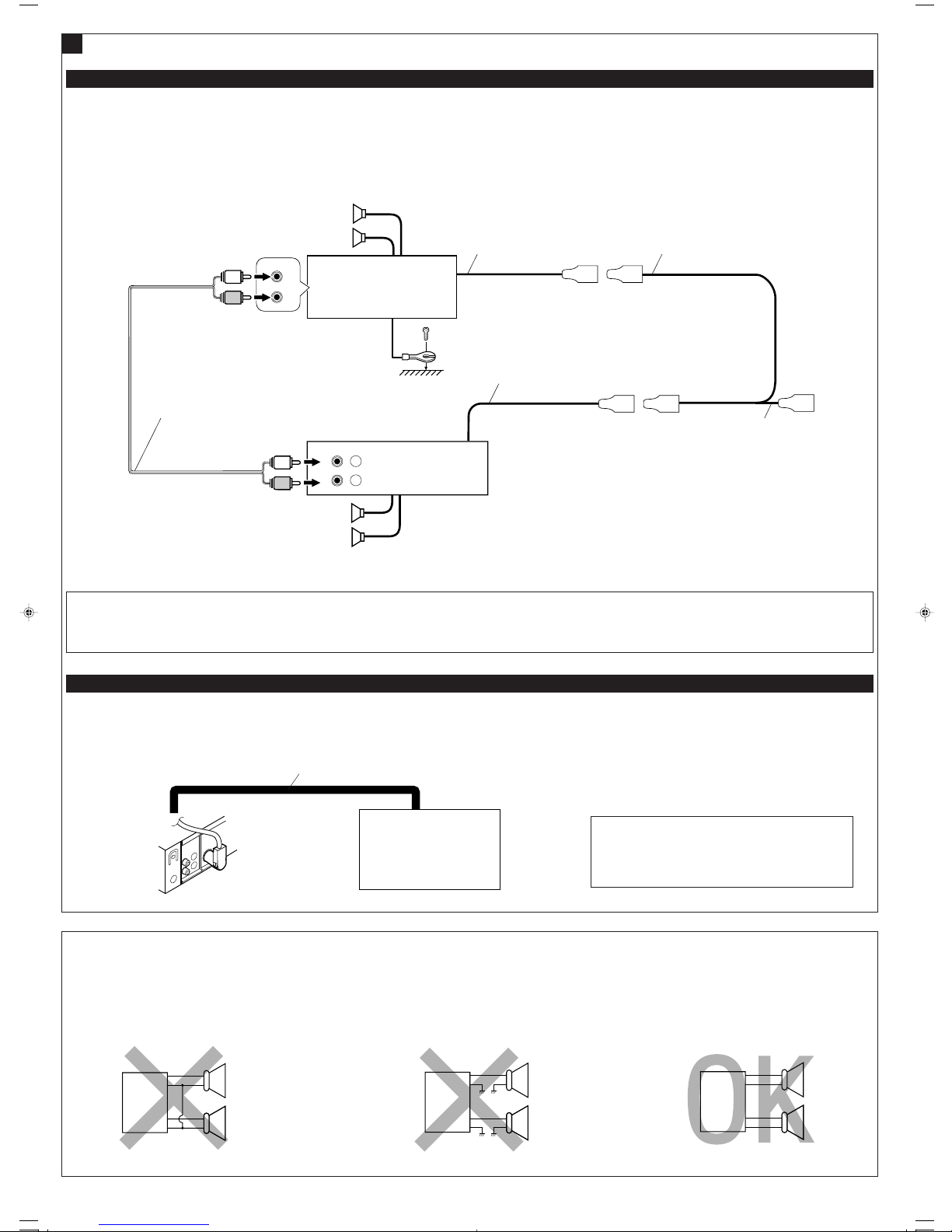
You can connect an amplifier to upgrade your car stereo system.
• Connect the remote lead (blue with white stripe) to the remote lead of the other equipment so
that it can be controlled through this unit.
• Disconnect the speakers from this unit, connect them to the amplifier. Leave the speaker
leads of this unit unused.
Connections Adding Other Equipment / °“√µËÕ‡æ‘Ë¡‡µ‘¡‡¢È“°—∫Õÿª°√≥ÏÕ◊Ëπ Ê
Amplifier / ‡§√◊ËÕߢ¬“¬
Rear speakers
≈”‚æßÀ≈—ß
Signal cord (not supplied for this unit)
“¬‡§‡∫‘≈—≠≠“≥ (‰¡Ë‰¥È„ÀÈ¡“°—∫™ÿ¥ª√–°Õ∫π’È)
To the remote lead of other equipment or automatic antenna if any
µËÕ“¬°—∫Õÿª°√≥ÏÕ◊ËπÀ√◊Õ‡“Õ“°“»Õ—µ‚π¡—µ‘∂È“¡’
Y-connector (not supplied for this unit)
¢ÈÕµËÕ√Ÿªµ—« Y (‰¡Ë‰¥È„ÀÈ¡“°—∫™ÿ¥ª√–°Õ∫π’È)
Remote lead (Blue with white stripe)
“¬µ–°—Ë«•–¬–‰°• (’πÈ”‡ß‘π≈“¬¢“«)
KS-FX385
KS-F185
B
Front speakers
≈”‚æßÀπÈ“
*3Firmly attach the ground wire to the metallic body or to the chassis of the car—to the place not
coated with paint (if coated with paint, remove the paint before attaching the wire). Failure to
do so may cause damage to the unit.
PRECAUTIONS on power supply and speaker connections:
• DO NOT connect the speaker leads of the power cord to the car battery; otherwise, the
unit will be seriously damaged.
• BEFORE connecting the speaker leads of the power cord to the speakers, check the speaker
wiring in your car.
Remote lead
“¬µ–°—Ë«•–¬–‰°•
CD Changer / ‡§√◊ËÕ߇≈Ëπ´’¥’ CD
Connecting cord supplied for your CD changer
“¬µËÕ„ÀÈ¡“æ√ÈÕ¡‡§√◊ËÕ߇≈Ëπ´’¥’
KS-FX385
CAUTION / ¢ÈÕ§«√√–«—ß
• Before connecting the CD changer, make sure that the unit
is turned off.
•
°ËÕπ®–‡™◊ËÕ¡µËÕ‡§√◊ËÕ߇≈Ëπ´’¥’ °√ÿ≥“µ√«®Õ∫„ÀÈ·πË„®«Ë“‡§√◊ËÕ߇≈Ëπ´’¥’π—Èπª‘¥Õ¬
Refer also to page 13 of the INSTRUCTIONS. / ¥Ÿ¢ÈÕ·π–π”„πÀπÈ“ 13
JVC CD changer
‡§√◊ËÕ߇≈Ëπ´’¥’ JVC
L
R
+
-
+
-
+
-
+
-
L
R
+
-
+
-
+
-
+
-
L
R
+
-
+
-
+
-
+
-
R
L
LINE OUT
REAR
L
L
R
L
R
FRONT
INPUT
R
L
R
*
3
JVC Amplifier
‡§√◊ËÕߢ¬“¬‡’¬ß JVC
§ÿ≥“¡“√∂µËÕ·Õ¡æ≈‘ø“¬‡ÕÕ√Ï ‡æ◊ËÕ‡æ‘Ë¡¡√√∂π–„ÀÈ√–∫∫‡µÕ√‘‚Õ‰¥È
• µËÕ“¬µ–°—Ë«√–¬–‰°≈ (’πÈ”‡ß‘π≈“¬¢“«) ‡¢È“°—∫“¬µ–°—Ë«√–¬–‰°≈¢ÕßÕÿª°√≥ÏÕ◊Ëπ Ê ‡æ◊ËÕ®–“¡“√∂§«∫§ÿ¡‚¥¬™ÿ¥ª√–°Õ∫π’ȉ¥È
• ∂Õ¥≈”‚æßÕÕ°®“°™ÿ¥ª√–°Õ∫π’È ·≈È«µËÕ‡¢È“°—∫‡§√◊ËÕߢ¬“¬ ∑‘Èß“¬µ–°—Ë«≈”‚æߢÕß™ÿ¥ª√–°Õ∫π’È ‰«È
*
3
µËÕ≈«¥“¬¥‘π„ÀÈ·πËπ‡¢È“°—∫µ—«∂—߇À≈Á° À√◊Õµ—«∂—ß√∂ ˙ µ√ßË«π ∑’ˉ¡Ë¡’’‡§≈◊Õ∫ (À“°¡’’‡§≈◊Õ∫Õ¬ŸË „ÀÈ¢Ÿ¥’ÕÕ°°ËÕπ
°ËÕπµËÕ≈«¥“¬¥‘π) À“°‰¡ËªØ‘∫—µ‘µ“¡§”·π–π”π’È ‡§√◊ËÕßÕ“®™”√ÿ¥À√◊Õ‡’¬À“¬‰¥
Only for KS-FX385 / KS-FX385 ‡∑Ë“π—Èπ
¢ÈÕ§«√√–«—ß”À√—∫°“√µËÕ·À≈Ë߮˓¬°”≈—ß·≈–≈”‚æß:
• լ˓µËÕ“¬µ–°—Ë«‡§‡∫‘≈°”≈—ߢÕß≈”‚æ߇¢È“°—∫·∫µ‡µÕ√’Ë√∂¬πµÏ ¡‘©–π—Èπ ™ÿ¥ª√–°Õ∫®–‰¥È√—∫§«“¡‡’¬À“¬¡“°
• °ËÕπ∑’Ë®–µËÕ“¬µ–°—Ë«‡§‡∫‘≈°”≈—ߢÕß≈”‚æ߇¢È“°—∫≈”‚æß „Àȵ√«®Õ∫°“√‡¥‘𓬉ø≈”‚æß„π√∂¢Õߧÿ≥„Àȇ√’¬∫√ÈÕ¬‡’¬°ËÕπ
Page 37

KS-FX385/KS-FX385S/KS-FX385G/
KS-F185/KS-F185S/KS-F185G
Installation/Connection Manual
Buku Panduan Instalasi/Penyambungan
0604DTSMDTJEIN
EN, IN
GET0225-006A
[UN]
J
Handles
Handle
F
Washer (ø5)
Ring (ø5)
G
Lock nut (M5)
Mur pengunci (M5)
H
Mounting bolt (M5 x 20 mm)
Baut pengganjal (M5 x 20 mm)
I
Rubber cushion
Bantalan karet
Parts list for installation and connection
The following parts are provided for this unit.
After checking them, please set them correctly.
A / B
Hard case/Control panel
Kotak/Panel kontrol
C
Sleeve
Mounting sleeve
D
Trim plate
Trim plate
E
Power cord
Kabel listrik
INSTALLATION (IN-DASH MOUNTING)
The following illustration shows a typical installation. If you have any questions or require
information regarding installation kits, consult your JVC car audio dealer or a company supplying
kits.
• If you are not sure how to install this unit correctly, have it installed by a qualified technician.
ENGLISH
This unit is designed to operate on 12 V DC, NEGATIVE ground electrical systems. If your
vehicle does not have this system, a voltage inverter is required, which can be purchased at
JVC car audio dealers.
1
INDONESIA
Unit ini dirancang untuk dipakai pada tegangan
12 V DC, dengan sistem negatif yang
di-ground-kan
. Jika peralatan anda tidak memiliki system ini, maka dibutuhkan sebuah perubah
tegangan, yang dapat dibeli di agen audio mobil JVC.
4
3
2
1
B
53 mm
184 mm
Ÿ
~
!
@
¤
D
I
H
C
D
B
J
C
*1
⁄
*1When you stand the unit, be
careful not to damage the fuse
on the rear.
*
1
Pada saat meletakkan unit pada
posisi berdiri, berhati-hatilah
agar sekering di bagian
belakang tidak rusak.
Do the required electrical connections.
Lakukan penyambungan listrik yang
diperlukan.
Bend the appropriate tabs to hold
the sleeve firmly in place.
Tekuk lempengan yang tepat untuk
menahan wadah unit secara kokoh
pada tempatnya.
Daftar alat-alat untuk instalasi dan penyambungan
Peralatan di bawah ini telah disediakan bersama-sama dengan unit.
Pastikan bahwa tidak ada peralatan yang hilang dan pasang dengan benar.
INSTALASI (PEMASANGAN PADA DASBOARD)
Ilustrasi berikut akan menjelaskan instruksi umum untuk instalasi. Apabila anda membutuhkan
informasi lebih lanjut, silakan konsultasi dengan dealer audio mobil JVC terdekat ataupun
perusahaan alat-alat elektronik.
• Apabila anda tidak mengetahui dengan pasti bagaimana memasang unit ini dengan benar,
tanyakan pada teknisi yang berpengalaman untuk pemasangannya.
Page 38

When installing the unit without using the sleeve/Instalasi unit tanpa mounting
sleeve
In a Toyota for example, first remove the car radio and install the unit in its place.
Sebagai contoh untuk mobil Toyota, lepaskan radio mobil terlebih dahulu dan kemudian pasang unit di tempat
yang sama.
Note : When installing the unit on the mounting bracket, make sure to use the 8 mm-long screws. If
longer screws are used, they could damage the unit.
Catatan :
Saat memasang unit pada bracket, gunakan baut yang berukuran 8 mm. Baut yang lebih
panjang dapat merusak unit.
When using the optional stay/Pemasangan pilihan
Stay (option)
Dudukan (pilihan)
Install the unit at an angle of less than 30˚.
Pasang unit tersebut pada sudut kurang dari 30˚.
2
Removing the unit
Before removing the unit, release the rear section.
TROUBLESHOOTING
• The fuse blows.
* Are the red and black leads connected correctly?
• Power cannot be turned on.
* Is the yellow lead connected?
• No sound from the speakers.
* Is the speaker output lead short-circuited?
• Sound is distorted.
* Is the speaker output lead grounded?
* Are the “–” terminals of L and R speakers grounded in common?
• Noise interfere with sounds.
* Is the rear ground terminal connected to the car’s chassis using shorter and thicker cords?
• Unit becomes hot.
* Is the speaker output lead grounded?
* Are the “–” terminals of L and R speakers grounded in common?
Bracket*
Bracket
*
Bracket*
Bracket
*
* Not included with this unit.
*
Tidak terdapat pada unit ini.
Flat type screws (M5 x 8 mm)*
Baut tipe flat (M5 x 8 mm)
*
Pocke t
Pocke t
Flat type screws (M5 x 8 mm)*
Baut tipe flat (M5 x 8 mm)
*
Screw (option)
Baut (pilihan)
Fire wall
Fire wall
Dashboard
Dasboard
31 2
B
D
J
Insert the two handles, then pull them as illustrated so that
the unit can be removed.
Masukkan kedua handle, kemudian tarik seperti
diilustrasikan sehingga unit tersebut dapat dikeluarkan.
H
F
G
C
Melepaskan unit
Sebelum melepaskan unit, lepaskan terlebih dahulu bagian belakangnya.
PEMECAHAN MASALAH
• Sekering terbakar.
*
Periksa apakah kabel merah dan hitam telah tersambung dengan benar?
• Unit tidak dapat dinyalakan.
*
Periksa apakah kabel kuning telah tersambung?
• Tidak ada suara dari speaker.
*
Periksa apakah ada korsleting pada kabel speaker?
• Suara tidak jelas.
*
Periksa apakah output speaker telah di-ground-kan?
*
Periksa apakah terminal “–” pada speaker kiri dan kanan telah di-ground-kan?
• Derau yang menyertai suara.
*
Apakah terminal ground di belakang unit terhubung ke sasis mobil yang menggunakan kabel tipis
dan pendek?
• Unit menjadi panas.
*
Periksa apakah speaker output telah di-ground-kan?
*
Periksa apakah terminal “–” pada speaker kiri dan kanan telah di-ground-kan?
Page 39
3
*2Before checking the operation of this unit prior to
installation, this lead must be connected, otherwise
power cannot be turned on.
*
2
Sebelum memeriksa pengoperasian unit ini sebelum
pemasangan, ujung kabel ini harus tersambung
terlebih dahulu, jika tidak power tidak akan dapat
dinyalakan.
15 A fuse
Sekering 15 A
Yellow*
2
Kuning
*
2
Blue with white stripe
Biru dengan garis putih
Red
Merah
Fuse block
Kotak sekering
To a live terminal in the fuse block connecting to the car battery
(bypassing the ignition switch) (constant 12 V)
Ke terminal live pada kotak sekering yang tersambung ke baterai mobil
(melewati sakelar semula) (12 V konstan)
To metallic body or chassis of the car
Ke bagian logam atau rangka kendaraan
*1Not included with this unit
*
1
Tidak terdapat pada unit ini
Black
Hitam
To an accessory terminal in the fuse block
Ke terminal aksesoris pada kotak sekering
Gray with black stripe
Kelabu dengan garis
hitam
White
Putih
White with black stripe
Putih dengan garis hitam
Green with black stripe
Hijau dengan garis hitam
Gray
Kelabu
Green
Hijau
Purple with black stripe
Ungu dengan garis
hitam
Purple
Ungu
Rear ground terminal
Terminal ground
belakang
To the remote lead of other equipment or automatic antenna if any (200 mA max.)
Untuk pengarah remote dari peralatan yang lain atau antena otomatis jika ada
(maksimum 200 mA)
Line out (see diagram )
Line out (lihat diagram )
A
Left speaker (rear)
Speaker kiri (belakang)
Right speaker (front)
Speaker kanan (depan)
Left speaker (front)
Speaker kiri (depan)
Right speaker (rear)
Speaker kanan (belakang)
Ignition switch
Kunci starter
Typical Connections/Penyambungan Khusus
Antenna terminal
Terminal antena
ELECTRICAL CONNECTIONS
To prevent short circuits, we recommend that you disconnect the battery’s negative terminal and
make all electrical connections before installing the unit.
• Be sure to ground this unit to the car’s chassis again after installation.
Notes:
• Replace the fuse with one of the specified rating. If the fuse blows frequently, consult your
JVC car audio dealer.
• Maximum input of the speakers should be more than 45 W at the rear and 45 W at the front, with
an impedance of 4 Ω to 8 Ω.
• To prevent short-circuit, cover the terminals of the UNUSED leads with insulating tape.
• The heat sink becomes very hot after use. Be careful not to touch it when removing this unit.
Heat sink
Penyerap panas
ENGLISH
Before connecting: Check the wiring in the vehicle carefully. Incorrect connection may cause
serious damage to this unit.
The leads of the power cord and those of the connector from the car body may be different in
color.
1
Connect the colored leads of the power cord in the order specified in the illustration below.
2
Connect the antenna cord.
3
Finally connect the wiring harness to the unit.
To CD Changer—only for KS-FX385/KS-FX385S/KS-FX385G (see diagram )
Untuk CD changer—hanya untuk KS-FX385/KS-FX385S/KS-FX385G (lihat diagram )
INDONESIA
1
2
*
1
*
1
1
2
3
4
5
3
15
PENYAMBUNGAN LISTRIK
Untuk mencegah terjadinya korsleting, sangat dianjurkan apabila anda mencabut terminal baterai
negatif dan memasang semua sambungan listrik sebelum memasang unit.
• Yakinkan kembali ground dari unit ini apakah sudah terpasang atau belum setelah
instalasi selesai.
Catatan:
•
Ganti sekering dengan sekering lain yang sesuai dengan syarat spesifikasi. Jika sekering sering
terbakar, tanyakan pada dealer audio mobil JVC.
•
Input maksimum speaker sebaiknya lebih dari 45 W pada bagian belakang dan 45 W pada
bagian depan dengan impedansi antara 4
Ω sampai 8 Ω
.
•
Untuk mencegah terjadinya korsleting, tutup ujung kabel yang tidak TERPAKAI dengan pita
insulator.
•
Penyerap panas akan menjadi sangat panas setelah pemakaian. Berhati-hatilah untuk tidak
menyentuhnya saat memindahkan unit ini.
Sebelum menghubungkan listrik:
Periksa kabel-kabel dalam peralatan anda dengan hati-hati.
Hubungan yang salah dapat menyebabkan kerusakan serius pada unit ini.
Kabel dalam kabel listrik dan juga konektor kendaraan memiliki warna yang berlainan.
1
Hubungkan petunjuk warna pada kabel power dalam urutan yang ditunjukkan pada ilustrasi di
bawah.
2
Sambungkan kabel antena.
3
Sambungkan sarung kabel dengan unit.
Page 40
4
You can connect an amplifier to upgrade your car stereo system.
• Connect the remote lead (blue with white stripe) to the remote lead of the other equipment so
that it can be controlled through this unit.
• Disconnect the speakers from this unit, connect them to the amplifier. Leave the speaker
leads of this unit unused.
Connections Adding Other Equipment/Sambungan pada peralatan lain
Amplifier/Amplifier
Rear speakers
Speaker belakang
Signal cord (not supplied for this unit)
Kabel sinyal (tidak disertakan dalam unit ini)
To the remote lead of other equipment or automatic antenna if any
Untuk pengarah remote dari peralatan yang lain atau antena otomatis
jika ada
Y-connector (not supplied for this unit)
Konektor-Y (tidak disertakan dalam unit ini)
Remote lead (Blue with white stripe)
Kabel remote (Biru dengan garis putih)
KS-FX385
KS-FX385S
KS-FX385G
B
Front speakers
Speaker depan
*3Firmly attach the ground wire to the metallic body or to the chassis of the car—to the place not
coated with paint (if coated with paint, remove the paint before attaching the wire). Failure to
do so may cause damage to the unit.
PRECAUTIONS on power supply and speaker connections:
• DO NOT connect the speaker leads of the power cord to the car battery; otherwise, the
unit will be seriously damaged.
• BEFORE connecting the speaker leads of the power cord to the speakers, check the speaker
wiring in your car.
Remote lead
Kabel remote
CD Changer/CD changer
Connecting cord supplied for your CD changer
Hubungkan kabel listrik pada CD changer anda
KS-FX385
KS-FX385S
KS-FX385G
CAUTION/PERHATIKAN
• Before connecting the CD changer, make sure that the unit
is turned off.
•
Sebelum CD changer dihubungkan pada sumber listrik,
pastikan unit tersebut dalam keadaan mati.
Refer also to page 13 of the INSTRUCTIONS.
Lihat juga ke halaman 13 dari BUKU PETUNJUK.
JVC CD changer
CD changer JVC
L
R
+
-
+
-
+
-
+
-
L
R
+
-
+
-
+
-
+
-
L
R
+
-
+
-
+
-
+
-
R
L
LINE OUT
REAR
L
L
R
L
R
FRONT
INPUT
R
L
R
*
3
JVC Amplifier
Amplifier JVC
Only for KS-FX385/KS-FX385S/KS-FX385G/Hanya untuk KS-FX385/KS-FX385S/KS-FX385G
KS-F185
KS-F185S
KS-F185G
Anda dapat menghubungkan sebuah penguat suara untuk meningkatkan sistem stereo mobil
anda.
•
Sambungkan ujung kabel remote (biru dengan garis putih) dengan ujung kabel remote
peralatan lain sehingga peralatan lain tersebut dapat dikontrol melalui unit ini.
• Cabut speaker dari sistem dan sambungkan pada amplifier. Biarkan ujung speaker yang
tidak terpakai.
*
3
Pasanglah dengan ketat kabel ground ke bagian logam atau rangka kendaraan—dengan
bagian yang tidak tertutupi oleh cat (apabila tertutup oleh cat, buanglah cat sebelum
memasang kabel). Bila tidak dibuang, dapat mengakibatkan kerusakan serius.
PENCEGAHAN pada power supply dan sambungan speaker:
• JANGAN sambung ujung kabel speaker dengan baterai mobil. Hal ini dapat
mengakibatkan kerusakan serius pada unit.
•
SEBELUM menyambung ujung kabel speaker dengan speaker, periksa dulu sistem
pengkabelan kendaraan anda.
 Loading...