

Page 1
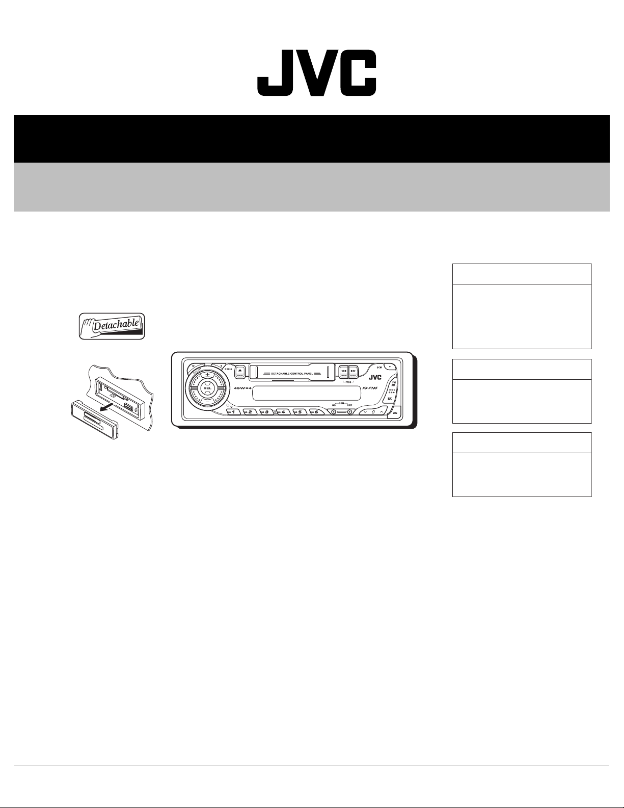
SERVICE MANUAL
CASSETTE RECEIVER
MA094B20053
KS-F185,KS-F185S,KS-F185G
KS-F185
Area suffix
UH ---------------------- Thailand
UN --------------------- Indonesia
U -------------------- Other Areas
KS-F185S
Area suffix
UN --------------------- Indonesia
KS-F185G
Area suffix
UN --------------------- Indonesia
TABLE OF CONTENTS
1 PRECAUTION. . . . . . . . . . . . . . . . . . . . . . . . . . . . . . . . . . . . . . . . . . . . . . . . . . . . . . . . . . . . . . . . . . . . . . . . . 1-3
2 SPECIFIC SERVICE INSTRUCTIONS . . . . . . . . . . . . . . . . . . . . . . . . . . . . . . . . . . . . . . . . . . . . . . . . . . . . . . 1-4
3 DISASSEMBLY . . . . . . . . . . . . . . . . . . . . . . . . . . . . . . . . . . . . . . . . . . . . . . . . . . . . . . . . . . . . . . . . . . . . . . . 1-5
4 ADJUSTMENT . . . . . . . . . . . . . . . . . . . . . . . . . . . . . . . . . . . . . . . . . . . . . . . . . . . . . . . . . . . . . . . . . . . . . . . 1-13
5 TROUBLESHOOTING . . . . . . . . . . . . . . . . . . . . . . . . . . . . . . . . . . . . . . . . . . . . . . . . . . . . . . . . . . . . . . . . . 1-17
COPYRIGHT © 2005 Victor Company of Japan, Limited
No.MA094B
2005/3
Page 2
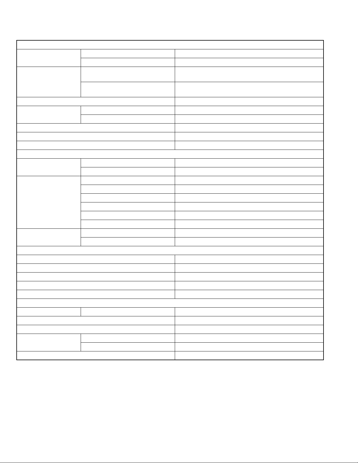
SPECIFICATION
AUDIO AMPLIFIER SECTION
Maximum Power Output Front 45 W per channel
Rear 45 W per channel
Continuous Power Output
(RMS)
Load Impedance 4 Ω (4 Ω to 8 Ω allowance)
Tone Control Range Bass ±10 dB at 100 Hz
Frequency Response 40 Hz to 20 000 Hz
Signal-to-Noise Ratio 70 dB
Line-Out Level/Impedance 1.0 V/20 kΩ load (250 nWb/m)
Frequency Range FM 87.5 MHz to 108.0 MHz
[FM Tuner] Usable Sensitivity 11.3 dBf (1.0 µV/75 Ω)
[AM Tuner] Sensitivity 20 µV
Wow & Flutter 0.15% (WRMS)
Fast-Wind Time 190 sec. (C-60)
Frequency Response 50 Hz to 14 000 Hz (Normal tape)
Signal-to-Noise Ratio 52 dB
Stereo Separation 40 dB
Power Requirement Operating Voltage DC 14.4 V (11 V to 16 V allowance)
Grounding System Negative ground
Allowable Operating Temperature 0ºC to +40ºC
Dimensions (W × H × D) Installation Size (approx.) 182 mm × 52 mm × 150 mm
Mass (approx.) 1.3 kg (excluding accessories)
Front 17 W per channel into 4 Ω, 40 Hz to 20 000 Hz at no more than
0.8% total harmonic distortion.
Rear 17 W per channel into 4 Ω, 40 Hz to 20 000 Hz at no more than
0.8% total harmonic distortion.
Treble ±10 dB at 10 kHz
TUNER SECTION
AM 531 kHz to 1 602 kHz
50 dB Quieting Sensitivity 16.3 dBf (1.8 µV/75 Ω)
Alternate Channel Selectivity (400 kHz) 65 dB
Frequency Response 40 Hz to 15 000 Hz
Stereo Separation 35 dB
Capture Ratio 2.0 dB
Selectivity 35 dB
CASSETTE DECK SECTION
GENERAL
Panel Size (approx.) 188 mm × 58 mm × 11 mm
Design and specifications are subject to change without notice.
1-2 (No.MA094B)
Page 3

1.1 Safety Precautions
SECTION 1
PRECAUTION
!
Burrs formed during molding may be left over on some parts of the chassis. Therefore,
pay attention to such burrs in the case of preforming repair of this system.
(No.MA094B)1-3
Page 4
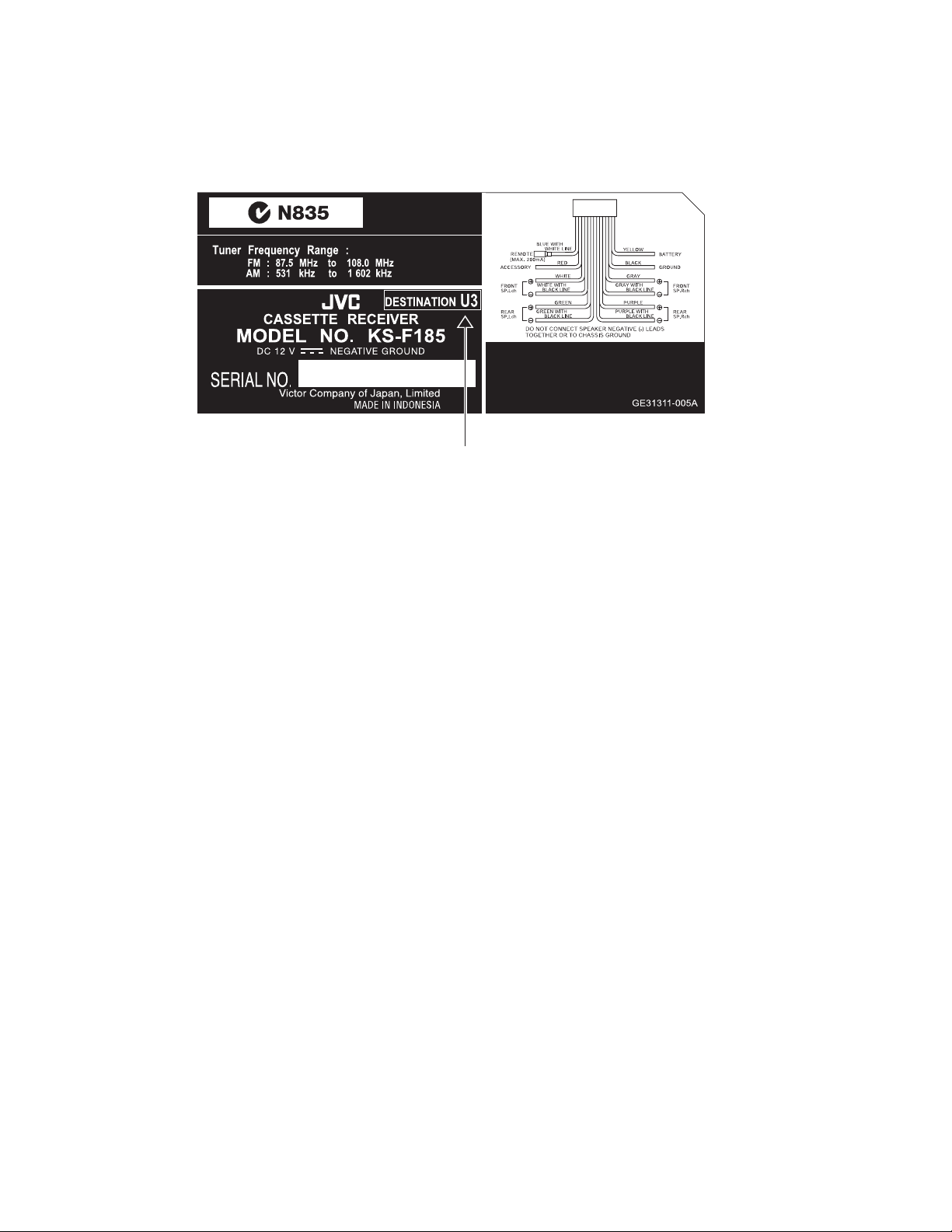
2.1 HOW TO IDENTIFY MODELS
2.1.1 NAME PLATE
SECTION 2
SPECIFIC SERVICE INSTRUCTIONS
Discernment sign
1-4 (No.MA094B)
Page 5
SECTION 3
DISASSEMBLY
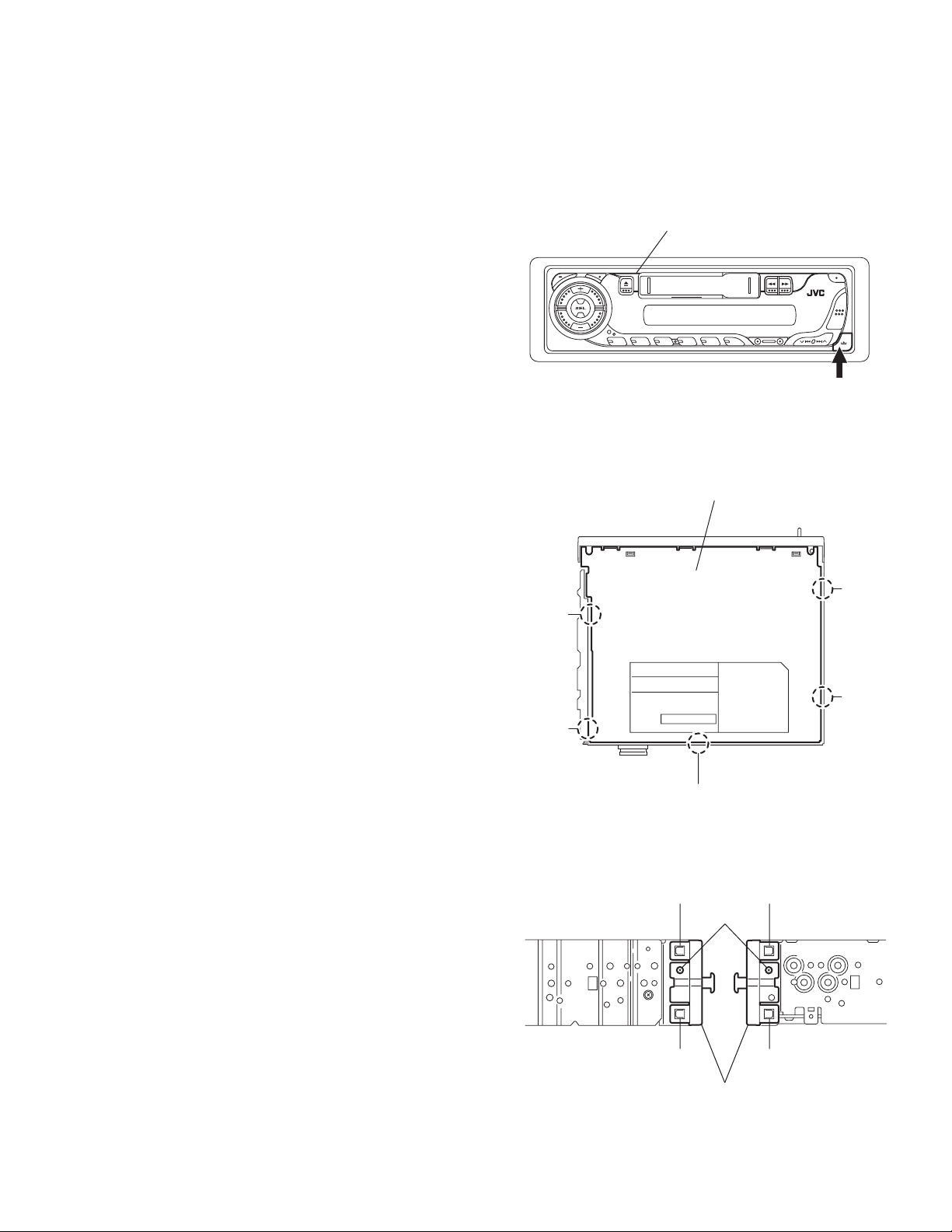
3.1 Main body
3.1.1 Removing the front panel assembly
(See Fig.1)
(1) Push the detach button and remove the front panel assem-
bly.
3.1.2 Removing the bottom cover
(See Fig.2)
• Prior to performing the following procedures, remove the front
panel assembly.
(1) Turn the body upside down.
(2) Insert a screwdriver under the joints to release the two
joints a on the left side, the two joints b on the right side and
the joint c on the back of the body, then remove the bottom
cover from the body.
CAUTION:
When releasing the joints using a screwdriver, do not damage
the board.
Joint a
Front panel assembly
Fig.1
Bottom cover
Detach button
Joint
b
3.1.3 Removing the front chassis assembly
(See Fig.3)
• Prior to performing the following procedures, remove the front
panel assembly and bottom cover.
(1) Remove the two screws A on each side of the body.
(2) Release the two joints d and the two joints e on the sides,
then remove the front chassis assembly toward the front.
Joint a
Joint c
Fig.2
Joint d Joint e
A
Joint d
Front chassis assembly
Fig.3
Joint e
Joint b
(No.MA094B)1-5
Page 6
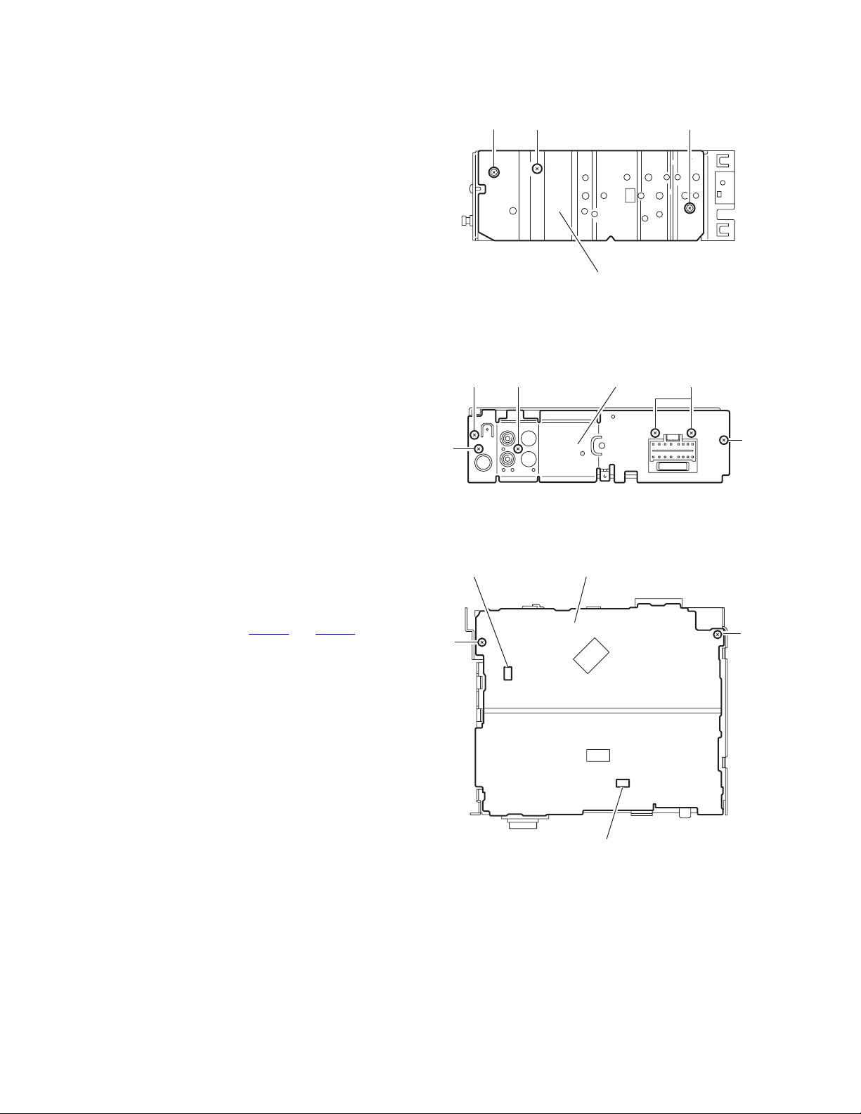
3.1.4 Removing the heat sink
(See Fig.4)
• Prior to performing the following procedure, remove the front
panel assembly.
(1) Remove the screw B and two screws C attaching the heat
sink on the left side of the body, and remove the heat sink.
3.1.5 Removing the rear panel
(See Fig.5)
• Prior to performing the following procedure, remove the front
panel assembly and bottom cover.
(1) Remove the two screws D , screw E and three screws F at-
taching the rear panel on the back of the body.
D
C
F
B
Heat sink
Fig.4
Rear panel
C
F
3.1.6 Removing the main board
(See Fig.6)
• Prior to performing the following procedures, remove the front
panel assembly, bottom cover, front chassis assembly, heat
sink and rear panel.
(1) Remove the two screws G attaching the main board on the
top chassis.
(2) Disconnect the two connectors (CN901
main board from the cassette mechanism assembly.
and CN721) on the
E
CN721
G
D
Fig.5
Main board
G
CN901
1-6 (No.MA094B)
Fig.6
Page 7

3.1.7 Removing the cassette mechanism assembly
(See Fig.7)
• Prior to performing the following procedure, remove the front
panel assembly, bottom cover, front chassis assembly, heat
sink, rear panel and main board.
(1) Remove the four screws H attaching the cassette mecha-
nism assembly from the top chassis.
H
Cassette mechanism assembly
H
3.1.8 Removing the head amplifier board
(See Fig.8)
• Prior to performing the following procedures, remove the front
panel assembly, bottom cover, front chassis assembly, heat
sink, rear panel, main board and cassette mechanism assembly.
(1) Disconnect the wire from CJ901 on the head amplifier
board.
(2) Remove the one screw J attaching the head amplifier
board.
(3) Move the head amplifier board in the direction of the arrow
to release the two joints f, the head amplifier board can be
removed.
3.1.9 Removing the relay board
(See Fig.9)
• Prior to performing the following procedures, remove the front
panel assembly, bottom cover, front chassis assembly, heat
sink, rear panel, main board and cassette mechanism assembly.
(1) Disconnect the wire from CP722
(2) Remove the one screw K attaching the relay board.
(3) Move the relay board in the direction of the arrow to release
the joint g, the relay board can be removed.
on the relay board.
H
CJ901
Joint f
To head relay board
Top chassis
Fig.7
Head amplifier board
Joint f
J
Fig.8
Relay board
H
CP722
Joint g
Fig.9
K
(No.MA094B)1-7
Page 8

3.1.10 Removing the mecha bracket
(See Fig.10)
• Prior to performing the following procedure, remove the front
panel assembly, bottom cover, front chassis assembly, heat
sink, rear panel, main board, cassette mechanism assembly,
head amplifier board and relay board.
(1) Remove the four screws L attaching the mecha bracket.
Mecha bracket
3.1.11 Removing the front board
(See Fig.11 to 13)
• Prior to performing the following procedures, remove the front
panel assembly.
(1) Remove the four screws M attaching the rear cover on the
back of the front panel assembly. (See Fig.11)
(2) Release the nine joints h, the front panel and the rear cover
become separate. (See Fig.12)
(3) Remove the front board from the rear cover. (See Fig.13)
Caution:
Take care not to lose the springs.
L
L
Fig.10
M Front panel assembly
M
M M
L
L
Joint h
Fig.11
Joint h
Joint h
Fig.12
Front board
Fig.13
1-8 (No.MA094B)
Page 9

3.2 Cassette mechanism assembly
• Prior to performing the following procedures, remove the head
amplifier board, the relay board and the mechanism bracket.
3.2.1 Removing the direction switch board
(See Fig.1)
(1) Unsolder the three wires a on the direction switch board.
(2) Remove the one screw A attaching the direction switch
board.
3.2.2 Removing the FF / REW lever assembly
(See Fig.1)
(1) Remove the screw B attaching the FF / REW lever assem-
bly on the back of the cassette mechanism assembly.
(2) Remove the screw C on the upper side of the FF / REW
lever assembly.
(3) Lift and pull forward the FF / REW lever assembly to disen-
gage the joints b, c, d and e.
3.2.3 Reattaching the FF / REW lever assembly
(See Fig.1)
(1) Reattach the FF / REW lever assembly to the joint c on the
back of the chassis.
(2) Reattach the pinch-roller shaft e, the change lever d and
the return link e to the chassis.
C
FF / REW lever assembly
Joint c
3.2.4 Removing the playback head
(See Fig.2)
• Prior to performing the following procedure, remove the direc-
tion switch board and the FF / REW lever assembly.
(1) Remove the screw D attaching the playback head.
(2) Remove the C washer and pull out the FF roller.
(3) Remove the S support plate, the A arm spring (a) and (b),
the playback head.
ATTENTION:
The A arm spring (a) differs from the A arm spring (b).
3.2.5 Removing the pinch-roller (R) and (F) assembly
(See Fig.2)
• Prior to performing the following procedure, remove the direc-
tion switch board and the FF / REW lever assembly.
(1) Remove the P arm spring (f) in the pinch-roller (F) assem-
bly from the chassis.
(2) Remove the P arm spring (r) in the pinch-roller (R) assem-
bly from the chassis.
(3) Draw out the pinch roller (F) and (R) assembly from the
shaft.
ATTENTION:
The P arm spring (f) differs from the P arm spring (r).
ATTENTION:
The pinch roller (F) assembly differs from the pinch roller (R)
assembly.
Joint e
Joint d
A
Soldering a
Direction switch board
Fig.1
Pinch-roller (R) assembly
Shaft
Remove the P arm spring (r)
from the chassis.
Joint b
B
C washer
A arm spring (b)
FF roller
S support plate
D
Playback head
Pinch-roller (F) assembly
A arm spring (a)
Shaft
Remove the P arm spring (f)
from the chassis.
P arm spring (r)
P arm spring (f)
Fig.2
(No.MA094B)1-9
Page 10

3.2.6 Removing the cassette hanger / cassette holder
(See Fig.3)
• Prior to performing the following procedure, remove the FF /
REW lever assembly.
(1) From the rear of the unit, bend the two tabs f outwards and
disengage the two joints g in the direction of the arrow.
(2) Push the eject lever and remove the cassette holder from
the playback head. Disengage the two joints h of the cassette hanger / cassette holder and the eject lever in the direction of the arrow.
(3) Lift the cassette hanger / cassette holder and disengage
the joint i of the return link and the eject lever.
Cassette holder
Cassette hanger
Chassis
Return link
Joint i
Eject lever
Joint h
Joint h
3.2.7 Removing the reel disc assembly
(See Fig.4)
• Prior to performing the following procedure, remove the FF /
REW lever assembly and the cassette hanger / cassette holder.
(1) Remove the C washer and pull out reel disc assembly.
ATTENTION:
Replace with a new C washer when reattaching.
3.2.8 Removing the motor assembly
(See Fig.5)
(1) Unsolder the two wires j on the motor assembly.
(2) Turn over the cassette mechanism assembly and remove
the main belt and the sub-belt from the motor pulley.
ATTENTION:
The main belt can now be removed.
(3) Remove the two screws G attaching the motor assembly.
Joint g
Flywheel (BF)
Tab f
C washer
C washer
Tab f
Fig.3
Fig.4
Main-belt
E
Joint g
Reel disc assembly
Motor assembly
Sub-belt
G
Motor pulley
1-10 (No.MA094B)
Flywheel (BR)
Reel base assembly
E
Fig.5
G
Soldering j
E
F
Page 11

3.2.9 Removing the Flywheel (BF) and (BR) assembly
(See Fig.4 and 5)
• Prior to performing the following procedure, remove the cas-
sette hanger / cassette holder.
(1) From the upper side of the cassette mechanism assembly,
remove the C washer from each shaft of the flywheel (BF)
and (BR).
(2) Turn over the cassette mechanism assembly and remove
the main belt. Pull out the flywheel (BF) and (BR) downward respectively.
C washer
Reel disc assembly
C washer
Fig.4
Main-belt
Motor assembly
3.2.10 Removing the reel base assembly
(See Fig.5 and 6)
(1) Raise the part k of the reel base assembly slightly and re-
move the selector link (B) on the front side of the cassette
mechanism assembly by turning it as shown in Fig.6.
(2) Remove the three screws E and the one screw F on the
underside of the cassette mechanism assembly.
ATTENTION:
The reel base assembly is not repairable. Handle with care.
Pinch-roller (R) assembly
k
Selector link (B).
Turn the selector link (B).
Fig.6
Inside of the reel base assembly
Flywheel (BF)
Flywheel (BR)
Sub-belt
E
Reel base assembly
E
Fig.5
Motor pulley
G
E
F
G
Soldering j
Fig.7
(No.MA094B)1-11
Page 12

3.2.11 Removing the mute switch board (See Fig.8)
(1) Unsolder the two wires l on the mute switch board on the
back of the cassette mechanism assembly.
(2) Remove the screw H attaching the mute switch board.
3.2.12 Removing the power switch
(See Fig.9)
• Prior to performing the following procedure, remove the motor
assembly.
(1) Unsolder the two wires m on the power switch on the side
of the cassette mechanism assembly.
(2) Remove the screw I attaching the power switch.
Cassette mechanism assembly
Soldering l
H
Fig.8
Soldering m
I
Cassette mechanism assembly
Power switch
Fig.9
Rower switch
Motor assembly
Mute switch board
1-12 (No.MA094B)
Page 13

SECTION 4
ADJUSTMENT
4.1 Adjustment method
Test instruments required for adjustment
(1) Digital oscilloscope (100MHz)
(2) Frequency counter meter
(3) Electric voltmeter
(4) Wow & flutter meter
(5) Test tapes
VT724 : For DOLBY level measurement
VT739 : For playback frequency measurement
VT712 : For wow flutter & tape speed measurement
VT703 : For head azimuth measurement
(6) Torque gauge : Cassette type for CTG-N (Mechanism adjustment)
Standard volume position
Balance and Bass, Treble volume, Fader : Center (Indication "0")
Loudness, Dolby NR, Sound, Cruise : Off
Volume position is about 2V at speaker output with following conditions, Playback the test tape VT721.
AM mode 999kHz/62dB, INT/400Hz, 30% modulation signal on receiving.
FM mono mode 97.9MHz/66dB, INT/400Hz, 22.5kHz deviation pilot off mono
FM stereo mode 1kHz, 67.5kHz dev. pilot 7.5kHz dev.
Output level 0dB (1µV,50Ω/open terminal)
Measuring conditions (Amplifier section)
Power supply voltage : DC14.4V (11V to 16V)
Load impedance : 4 Ω (4 Ω to 8 Ω allowance)
Line out : 1.0V/20kΩload (250 nWb/m)
(No.MA094B)1-13
Page 14
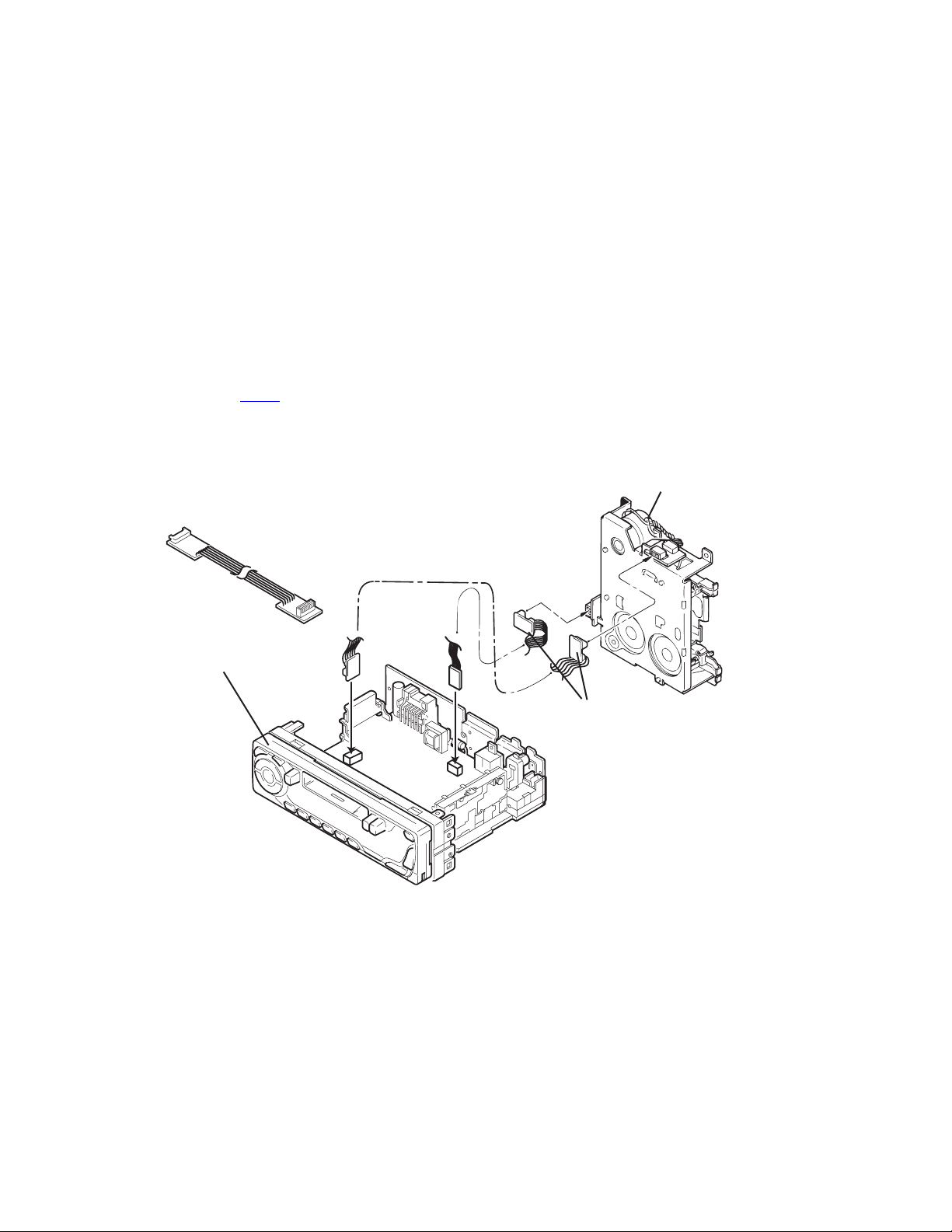
Information for using a car audio service jig
(1) We're advancing efforts to make our extension cords common for all car audio products.
Please use this type of extension cord as follows.
(2) As a U-shape type top cover is employed, this type of extension cord is needed to check operation of the mechanism assembly
after disassembly.
(3) Extension cord : EXTKSRT002-6P ( 6 pin extension cord ) For connection between mechanism assembly3. Extension cord :
EXTKSRT002-6P ( 6 pin extension cord ) For connection between mechanism assembly and main board.
(4) Check for mechanism driving section such as motor ,etc.
Disassembly method
(1) Remove the front panel assembly.
(2) Remove the bottom cover.
(3) Remove the front chassis assembly.
(4) Remove the heat sink.
(5) Remove the main board.
(6) Reattach the heat sink with the screw B. (Refer to Disassembly method.)
(7) Reattach the front panel assembly.
(8) Confirm that current is being carried by connecting an extension cord jig.
NOTE:
Available to connect to the CJ701
CAUTION :
Be sure to attach the heat sink on the power amplifier IC of a main board when supplying the power.
If voltage is applied without attaching the heat sink, the power amplifier IC will be destroyed by heat.
connector when installing the front panel.
Cassette mechanism
EXTKSRT002-6P
Front Panel assembly
Extension cord
: EXTKSRT002-6P
Main board
1-14 (No.MA094B)
Page 15
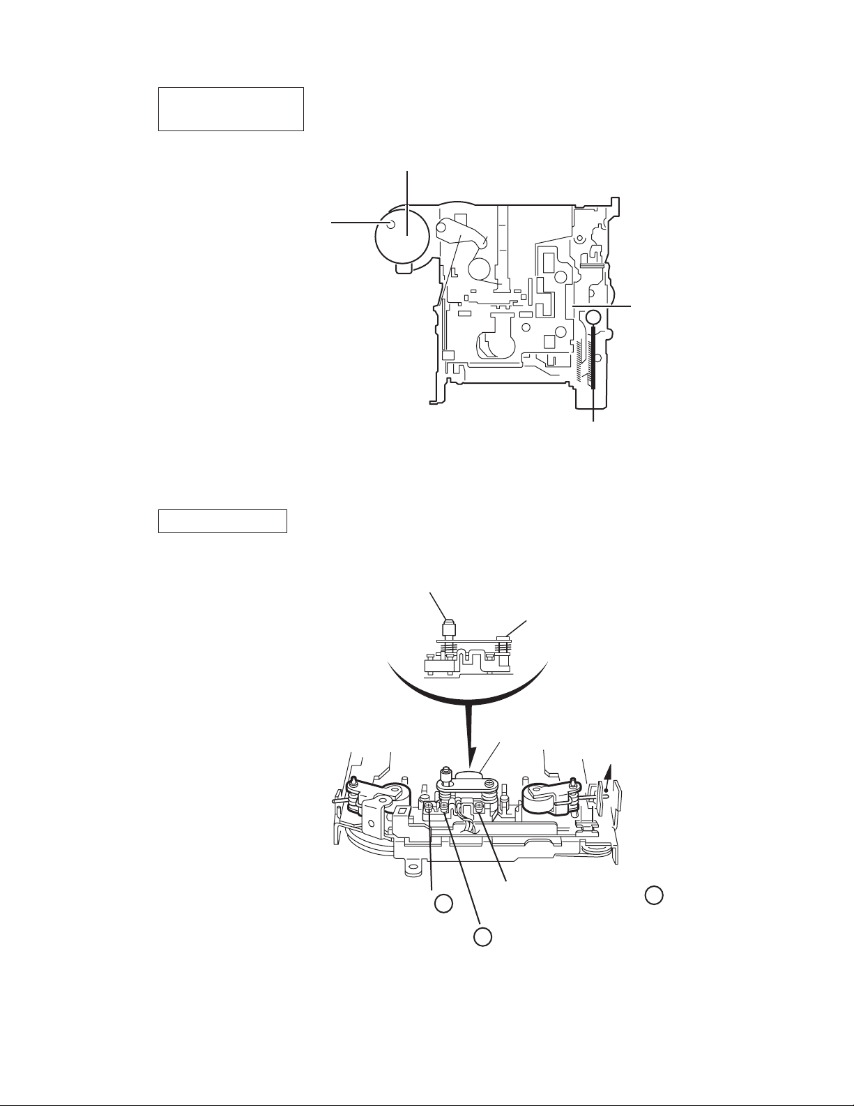
4.2 Arrangement of Adjusting & Test points
Cassette mechanism
(Surface)
Tape speed adjust
Motor assembly
Playback head
Azimuth screw
Head section view
Head azimuth screw
Height adjusting screw c
Fixed screw
Playback head
Height adjusting screw a
Height adjusting screw b
(No.MA094B)1-15
Page 16

Item
Conditions
Adjustment and Confirmation methods
S.Values Adjust
Head
1.
azimuth
adjustment
Test tape:
SCC-1659
VT703 (10kHz)
Test tape:
VT724 (1kHz)
VT703 (10kHz)
VT721 (315Hz)
Head height adjustment
Adjust the azimuth directly. When you
adjust the height using a mirror tape,
remove the cassette housing from the
mechanism chassis.
After installing thecassette housing,
perform the azimuth adjustment.
Load the SCC-1659 mirror tape. Adjust with
1.
height adjustment screw A and azimuth
adjustment screw B so that line A of the
mirror tape runs in the center between Lch
and Rch in the reverse play mode.
After switching from REV to FWD then to
2.
REV, check that the head position set in
procedure 1 is not changed. (If the position
has shifted, adjust again and check.)
Adjust with azimuth adjustment screw B so
3.
that line B of the mirror tape runs in the
center between Lch and Rch in the forward
play mode.
Head azimuth adjustment
Load VT724 (1kHz) and play it back in
1.
the reverse play mode.
Set the Rch output level to max.
Load VT703 (10kHz) and play it back in
2.
the forward play mode. Adjust the Rch
and Lch output levels to max, with
azimuth adjustment screw B. In this case,
the phase difference should be within 45 .
Engage the reverse mode and adjust the
3.
output level to max, with azimuth
adjustment screw C.
(The phase difference should be 45 or
more.)
When switching between forward and
4.
reverse modes, the difference between
channels should be within 3dB. (Between
FWD L and R, REV L and R.)
A line
Head shield
The head is at low position
during.
B line
Head shield
The head is at High position
during REV.
Output
level:
Maximum
PBHead
FWD Adj B
REV Adj C
(0 ) (45 )
HEIGHT Adj A
phase
2.
Tape speed
and wow
flutter
confirmation
3.
Play back
frequency
response
confirmation
1-16 (No.MA094B)
When VT721 (315Hz) is played back,
5.
the level difference between channels
should be within 1.5dB.
Test tape: VT712
(3kHz)
Test tape: VT724
(1kHz)
VT739
(63Hz / 1kHz / 10kHz)
The tuner section is of an adjustment-freedesign. In case the tuner is in trouble, replace the tuner pack.
Check to see if the reading of the F, counter /
1.
wow flutter meter is within 3015Hz to 3045Hz
(FWD/ REV), and less than 0.35% (JIS RMS).
In case of out of specification, adjust the
2.
motor with a built-in volume resistor.
Play test tape VT724, and set the volume
1.
position at 2V.
Play test tape VT739 and confirm.
2.
1kHz / 10kHz: -1 3dB,
1kHz / 63Hz: 0 3dB,
When 10kHz is out of specification, it will be
3.
necessary to read adjust the azimuth.
Tape speed:
3015Hz
to 3045Hz
Wow
flutter: less
than 0.35%
Speaker out
1kHz / 63Hz
: 0 3dB
1kHz / 10kHz
: -1 3dB
Built-in volume
resistor
Page 17

5.1 16 PIN CORD DIAGRAM
SECTION 5
TROUBLESHOOTING
8
7
6
5
4
3
2
1
BK
RD
NC
BL/WH
WH
GN
VI
GY
WH/BK
GN/BK
GY/BK
16 YL
8 BK
7 RD ACC
5 BL/WH REMOTE
4 WH
12 WH/BK
3 GN
11 GN/BK RL-
2 VI RR+
10 VI/BK
1 GY FR+
YL
NC
NC
NC
VI/BK
16
15
14
13
12
11
10
9
MEMORY
GND
FL+
FL-
RL+
RR-
BK
RD
BL
WH
Black
Red
Blue
White
GN
VI
GY
YL
Green
Violet
Gray
Yellow
9 GY/BK
RR
FR
FL
RL
Rear Right
Front Right
Front Left
Rear Left
FR-
REMOTE
ACC
MEMORY
GND
Remote out
ACC Line
Memory Backup Battery +
Ground
(No.MA094B)1-17
Page 18

Victor Company of Japan, Limited
AV & MULTIMEDIA COMPANY CAR ELECTRONICS CATEGORY 10-1,1chome,Ohwatari-machi,Maebashi-city,371-8543,Japan
(No.MA094B)
Printed in Japan
VPT
Page 19

PARTS LIST
[ KS-F185 ] [ KS-F185S ]
[ KS-F185G ]
* All printed circuit boards and its assemblies are not available as service parts.
KS-F185
Area suffix
UH ---------------------- Thailand
UN --------------------- Indonesia
U -------------------- Other Areas
KS-F185S
Area suffix
UN --------------------- Indonesia
KS-F185G
Area suffix
UN --------------------- Indonesia
- Contents -
Exploded view of general assembly and parts list (Block No.M1)
Cassette mechanism assembly and parts list (Block No.MP)
Electrical parts list (Block No.01~03) (F185_UH,UN,U) (F185S/F185G_UN)
Electrical parts list (Block No.04~06) (F185_UH3,UN3,U3)
Packing materials and accessories parts list (Block No.M3)
3-2
3-5
3-10
3-12
3-16
MA094B
3-1
Page 20

Exploded view of general assembly and parts list
Block No.
1
A
M
M
1
M
13
11
14
B
10
2
13
5
4
5
12
12
12
5
5
15
40
41
Switch board
3-2
24
23
25
26
22
28
32
30
27
31
31
29
34
31
51
33
36
41
52
35
44
45
49
37
42
39
38
Page 21

M
M
8
56
6
9
3
54
57
8
6
59
B
58
53
A
55
Main board
19
21
18
20
7
17
7
16
4
4
15
49
45
44
47
43
50
46
48
3-3
Page 22

General Assembly
Symbol No. Part No. Part Name Description Local
1 GE10043-012A TOP CHASSIS
2 GE40135-001A EARTH PLATE
3 GE30938-003A SIDE PANEL
4 QYSDST2004ZA TAP SCREW M2 x 4mm(x2)
5 QYSDST2604ZA TAP SCREW M2.6 x 4mm(x4 )
6 GE40235-001A SCREW (x2)
7 QYSDST2606ZA TAP SCREW M2.6 x 6mm(x2 )
8 QYSDST2604ZA TAP SCREW M2.6 x 4mm(x2 )
9 QYSDST2610Z A TAP SCREW M2.6 x 10mm
10 VKL7821-002 EJECT LEVER
11 QYSPSPT2625ZA SCREW M2.6 x 2.5mm
12 QYSDSP2604ZA SCREW M2.6 x 4mm(x4)
13 QYSDST2605ZA TAP SCREW M2.6 x 5mm(x2)
14 GE20134-002A MEC HA BKT
15 GE10095-001A FR O NT CHASSIS
16 GE31033-001A LO C K LEVER
17 FSKW4005-003 TORSION SPRING
18 GE40202-005A COMPRESSION SPRING
19 GE31034-001A RLS KNOB
20 FSJC3014-002 CASSETTE LID
21 VKW4947-002 DOOR SPRING
22 GE10093-003A FRONT PANEL F185GUN
22 GE10093-002A FRONT PANEL F185SUN
22 GE10093-001A FRONT PANEL
23 GE31353-007A FINDER ASSY F185GUN
23 GE31353-006A FINDER ASSY F185SUN
23 GE31353-005A FINDER ASSY
24 GE31044-001A POWER BUTTON
25 GE31345-001A PLUS MINUS BTN
26 GE31346-001A SEL BUTTON
27 GE31347-001A SCM BTN
28 FSXP3065-0 02 EJECT BUT TON
29 FSXP3066-001 FF BUTTON
30 FSXP3067-001 REW BUTTON
31 FSKW3002-003 COMP.SPRING (x3)
32 FSJK3014-001 LIGHT LENS
33 GE20161-001A PRESET BUTTON
34 FSYH4036-031 SHEET
35 GE31024-006A UP/DOWN BTN
36 GE31028-003A SSM BTN
37 GE31025-003A SEARCH BTN
38 GE31032-007A DETACH BTN F185GUN
38 GE31032-006A DETACH BTN F185SUN
38 GE31032-005A DETACH BTN
39 GE40202-003A COMPRESSION SPRING
40 GE10094-001A REAR COVER
41 VKZ4777-010 MINI SCREW (x4)
42 GE31348-001A LCD CASE
43 GE31349-001A LENS CASE
44 GE31350-001A LCD LENS
45 GE40232-001A LIGHTING SHEET
46 GE30393-002A BOTTOM COVER
47 FSMA3004-203 INSU LATOR
48 GE31317-001A NAME PLATE F185GUN
48 GE31314-001A NAME PLATE F185SUN
48 GE31311-004A NAME PLA TE F185U
48 GE31311-005A NAME PLA TE F185U3
48 GE31311-001A NAME PLATE F185UH,F185UN
48 GE31311-003A NAME PLA TE F185UH3,F185UN3
49 QLD0333-001 LCD MODULE
50 QNZ0440-001 LCD CONNECTOR
51 QLL0033-003 LAMP
52 QLL0033-003 LAMP
53 QMFZ047-150-T FUSE 15A
54 GE30912-017A REAR BRACKET
55 QYSDST2606Z A TAP SCREW M2.6 x 6mm
56 QYSDSF2606ZA TAP SCREW M2.6 x 6mm(x2)
57 QYSDSF2606Z A TAP SCREW M2.6 x 6mm
58 GE40172-004A IC BRACKET
59 GE40240-001A REG IC BRACKET
F185U,F185 U3,F185UH,F185UH3,F185UN
,F185UN3
F185U,F185 U3,F185UH,F185UH3,F185UN
,F185UN3
F185U,F185 U3,F185UH,F185UH3,F185UN
,F185UN3
Block No. [M][1][M][M]
3-4
Page 23

Cassette mechanism assembly and parts list
CDS-363SJ2
Block No.
M
M
M
P
30
12
81
66
109
78
72
49
24
21
32
89
100
120
116
97
57
106
2
105
109
119
45
46
123
107
53
23
69
31
93
114
121
68
47
109
115
65
71
67
61
61
25
58
110
19
76
83
107
118
8
109
20
22
62
6
73
109
42
107
43
40
44
54
70
63
79
35
117
38
4
117
39
106
37
41
7
77
107
10
50
82
48
26
9
74
87
106
86
122
94
95
101
117
85
80
3-5
Page 24

Cassette mechanism
Symbol No. Part No. Part Name Description Local
2 X-0363-10 02S HEAD PLATE ASSY
4 X-0363-6001S REEL BASE ASSY
6 X-0363-6003S TU GEAR ARM ASSY
7 X-0363-6004S PINCH ARM(R) ASSY
8 X-0363-6005S PINCH ARM(F) ASSY
9 X-0363-6006S DETECTOR CAM ASSY (x2)
10 X-0363-2005S REEL SPINDLE ASSY (x2)
12 X-0036 -1 019S EJ.CA M LO CK ASY
19 1-0036-1065S FF LEVER(JVC)
20 1-0036-1066S REW LEVER(JVC)
21 1-0036-1007S EJECT LEVER
22 1-0036-1013S LOCK ARM
23 1-0036-1015S SPG SUPPORT PLT
24 1-0036-1018S CENTER PLATE
25 1-0036-1023S CHANGE LEVER(B)
26 1-0036-1026S FR ARM(B)
30 1-0138-1002S CASSETTE HANGER
31 1-0138-1006S ADJUSTER SHIN(X
32 1-0138-1010S CASSETTE HOLDER
35 1-0363-1003S EJECT CAM
37 1-0036-2001S IDLE GEAR
38 1-0036-2003S REDUCT.GEAR(B)
39 1-0036-2004S REDUCT.GEAR(A)
40 1-0036-2007-5S RATCHET
41 1-0036-2009S SENSOR ARM
42 1-0036-2010S SELECTOR GEAR
43 1-0036-2014S DETECTOR GEAR
44 1-0038-2014S GEAR LOCK ARM
45 1-0038-2018S TAPE GUIDE
46 1-0363 -2 006S ADJUSTER LIN K B
47 1-0138-2005-3S ADJUSTER ARM(B)
48 1-0036-2005S PULLEY GEAR
49 1-0032-2007S TAPE HOOKER
50 1-0058-2021-5S IDLE PULLEY(A)
53 1-0363-3018S FF ROLLER
54 1-0036-3018S COLLER
57 1-0363-3007S HP ROLLER(A)
58 1-0363-3011S PROGRAM ROLLER
61 1-0036-4001S FF/REW LEVER SP
62 1-0036-4002S LOCK LEVER SPG
63 1-0036-4003S GEAR LOCK ARM S
65 1-0036-4006S HEAD PLATE SPG
66 1-0036-4007S EJ.CA M LO CK SPG
67 1-0036-4008S PROGRAM ARM SPG
68 1-0036-4010S ADJUST ARM SP(A
69 1-0036-4011S ADJUST ARM SP(B
70 1-0036-4015S DASH SPG
71 1-0036-4017S CHANGING ARM SP
72 1-0036-4023S CENTER PLT SP(B
73 1-0038-4014S RATCHET SPG
74 1-0138-4001S BACK TEMSION SP
76 1-0363 -4 003S PINCH ARM SPG F
77 1-0363 -4 004S PINCH ARM SPG R
78 1-0363 -4 005S EJECT LEVE R SPG
79 1-0036 -4 005S EJECT CAM SPG
80 1-0036-5020S MAIN BELT(AL)
81 1-0363-5007S RETURN LINK
82 1-0036-5001S SUB BELT
83 1-0363-5003S SEL EC TO R LI N K B
85 1-0036-7002S WIRE(A)
86 1-0036-7003S WIRE(B)
87 1-0036-7073S WIRE(AL)
89 X-0363-7006S MOTOR ASSY
93 1-0363-7001S MUTE SW
94 1-0036-7007-1S SLIDE SW
95 1-0363-7008S SLIDE SW PWB
97 1-0036-7034S POWER SW
100 1-0036-7089S 6P WIRE ASY(JVC
101 1-0036-7088S 5P WIRE ASY(JVC
105 2-1816-0032-E8S MYLAR WASHER(S) (x2)
106 2-1812-0030-D2S PSW-S (x3)
107 1-0036-5024S PSW(REEL) (x5)
109 2-1712- 0050-16S E RING (x5)
1 10 2-1712-5060-16S E RING
Block No. [M][P ] [M][M]
3-6
Page 25

Symbol No. Part No. Part Name Descript i on Local
114 1-0363-7015S MUTE SWITCH BOARD
115 2-1331-7040-C2S SCREW S
116 2-1331-7060-C2S SCREW S
117 2-1382-0030-C2S SCREW B (x5)
118 2-1332-0040-C1S SCREW S
119 2-1032-0070-C2S SCREW (x2)
120 2-1032-0025-C2S SCREW (x2)
121 2-1012-0040-C2S SCREW
122 2-1012-0030-F2S SCREW
123 1-0138-5002S AZIMUTH SCREW (x3)
3-7
Page 26

Grease point 1/2
Grease
FL-942
SW-902
SW-522B
FG-84M
C68
EP-56
1
Reverse side
A
24
2
72
3-8
Page 27

Grease point 2/2
19
20
5
35
30
12
3
38
16
39
42
37
43
4
15
3-9
Page 28

Electrical parts list
Main board
Symbol No.
Part No. Part Name Description Local
(F185_UH,UN,U) (F185S/F185G_UN)
Block No. [0] [1 ]
Symbol No.
IC701 LC72362N-9C64 IC
IC781 AN80T05LF IC
IC931 PT2319-L-X IC
IC981 LA4743K POWER IC
Q1 2SA1706/ST/-T TRANSISTOR
Q2 KRC102M-T DIGI TRANSISTOR
Q3 KTA1267/YG/-T TRANSISTOR
Q4 KRC102M-T DIGI TRANSISTOR
Q5 KRC102M-T DIGI TRANSISTOR
Q161 2SD2144S/VW/-T TRANSISTOR
Q261 2SD2144S/VW/-T TRANSISTOR
Q701 KTC3199/GL/-T TRANSISTOR
Q771 KTC3199/GL/-T TRANSISTOR
Q772 KTC3199/GL/-T TRANSISTOR
Q781 KRC1 02 M - T DIGI TRANSISTOR
Q782 2SA1706/ST/-T TRANSISTOR
Q783 KRC1 02 M - T DIGI TRANSISTOR
Q784 2SA1706/ST/-T TRANSISTOR
Q789 KRA102M-T DIGI TRANSISTOR
Q971 KRC1 02 M - T DIGI TRANSISTOR
Q972 KRA102M-T DIGI TRANSISTOR
Q987 KRA102M-T DIGI TRANSISTOR
Q988 KRC1 02 M - T DIGI TRANSISTOR
Q989 KRA102M-T DIGI TRANSISTOR
D1 1SS119-041-T2 DIODE
D2 1SS119-041-T2 DIODE
D3 1SS119-041-T2 DIODE
D4 1SS119-041-T2 DIODE
D161 1SS119-041-T2 DIODE
D261 1SS119-041-T2 DIODE
D704 MTZJ6.2B-T2 Z DIODE
D705 MTZJ6.2B-T2 Z DIODE
D706 MTZJ6.2B-T2 Z DIODE
D707 MTZJ6.2B-T2 Z DIODE
D708 MTZJ6.2B-T2 Z DIODE
D709 MTZJ6.2B-T2 Z DIODE
D711 MTZJ6.2B-T2 Z DIODE
D713 1SS119-041-T2 DIODE
D714 1SS119-041-T2 DIODE
D716 1SS119-041-T2 DIODE
D718 1SS119-041-T2 DIODE
D771 MTZJ9.1C-T 2 Z DI O DE
D781 1SS119-041-T2 DIODE
D782 1SS119-041-T2 DIODE
D784 1A3G-T1 SI DIODE
D785 1A3G-T1 SI DIODE
D786 1A3G-T1 SI DIODE
D791 1SS119-041-T2 DIODE
D792 1SS119-041-T2 DIODE
D961 RB721Q-40-T2 DIODE
D973 1SS119-041-T2 DIODE
D974 1SS119-041-T2 DIODE
D981 1N5401-TM SI DIODE
D990 MTZJ11B-T2 Z DIODE
C2 QDX11EK-223Z C CAPACITOR 0.022uF 25V K
C3 Q EKJ 1HM-104Z E CAPACITOR 0.1uF 50V M
C4 Q EKJ 1HM-104Z E CAPACITOR 0.1uF 50V M
C5 QEKJ1CM-106Z E CAPACITOR 10uF 16V M
C6 QDX11EK-223Z C CAPACITOR 0.022uF 25V K
C7 QDX11EK-223Z C CAPACITOR 0.022uF 25V K
C8 QERF1H M-104 Z E CAPACITOR 0.1uF 50V M
C9 QDYB1CM-103Y C CAPACITOR 0.01uF 16V M
C11 Q CBB1HK-331Y C CAPACITOR 330pF 50V K
C12 Q CBB1HK-271Y C CAPACITOR 270pF 50V K
C15 Q DYB1CM-103Y C CAPACITOR 0.01uF 16V M
C131 QERF1HM-105Z E CAPACITOR 1uF 50V M
C132 QERF1HM-105Z E CAPACITOR 1uF 50V M
Part No. Part Name Description Local
C134 QFV61HJ-823Z MF CAPACITOR 0.082uF 50V J
C135 QFV61HJ-823Z MF CAPACITOR 0.082uF 50V J
C136 QFV61HJ-154Z MF CAPACITOR 0.15uF 50V J
C137 QFV61HJ-154Z MF CAPACITOR 0.15uF 50V J
C138 QCFB1HZ-104Y C CAPACI TOR 0.1uF 50V Z
C150 QERF1HM-225Z E CAPACITOR 2.2uF 50V M
C160 QERF1HM-225Z E CAPACITOR 2.2uF 50V M
C231 QERF1HM-105Z E CAPACITOR 1uF 50V M
C232 QERF1HM-105Z E CAPACITOR 1uF 50V M
C234 QFLA1HJ-152Z M CAPACITOR 1500pF 50V J
C235 QFV61HJ-823Z MF CAPACITOR 0.082uF 50V J
C236 QFV61HJ-823Z MF CAPACITOR 0.082uF 50V J
C237 QFV61HJ-154Z MF CAPACITOR 0.15uF 50V J
C238 QFV61HJ-154Z MF CAPACITOR 0.15uF 50V J
C250 QERF1HM-225Z E CAPACITOR 2.2uF 50V M
C260 QERF1HM-225Z E CAPACITOR 2.2uF 50V M
C701 QDUB1HJ-270Y C CAPACITOR 27pF 50V J
C702 QDCB1HJ-220Y C CAPACITOR 22pF 50V J
C703 QERF0JM-107Z E CAPACITOR 100uF 6.3V M
C704 QFV61HJ-224Z MF CAPACITOR 0.22uF 50V J
C705 QERF1CM-106Z E CAPACITOR 10uF 16V M
C706 QDYB1CM-103Y C CAPACITOR 0.01u F 16V M
C707 QFV61HJ-103Z MF CAPACITOR 0.01uF 50V J
C708 QCFB1HZ-104Y C CAPACI TOR 0.1uF 50V Z
C709 QERF1HM-474Z E CAPACITOR 0.47uF 50V M
C710 QCFB1HZ-104Y C CAPACI TOR 0.1uF 50V Z
C771 QERF1AM-227Z E CAPACITOR 220uF 10V M
C772 QERF1HM-225Z E CAPACITOR 2.2uF 50V M
C773 QDGB1HK-102Y C CAPACITOR 1000pF 50V K
C781 QERF1CM-106Z E CAPACITOR 10uF 16V M
C783 QETN0JM-228Z E CAPACITOR 2200uF 6.3V M
C784 QERF1AM-227Z E CAPACITOR 220uF 10V M
C785 QERF1CM-106Z E CAPACITOR 10uF 16V M
C786 QERF1AM-227Z E CAPACITOR 220uF 10V M
C931 QEKJ1AM-107Z E CAPACITOR 100uF 10V M
C932 QCFB1HZ-104Y C CAPACI TOR 0.1uF 50V Z
C933 QERF1HM-105Z E CAPACITOR 1uF 50V M
C934 QERF1CM-226Z E CAPACITOR 22uF 16V M
C940 QERF1HM-105Z E CAPACITOR 1uF 50V M
C941 QERF1HM-105Z E CAPACITOR 1uF 50V M
C942 QFLA1HJ-152Z M C APACITOR 1500pF 50V J
C943 QERF1HM-105Z E CAPACITOR 1uF 50V M
C972 QERF1AM-227Z E CAPACITOR 220uF 10V M
C974 QFV61HJ-224Z MF CAPACITOR 0.22uF 50V J
C975 QFV61HJ-224Z MF CAPACITOR 0.22uF 50V J
C976 QFV61HJ-224Z MF CAPACITOR 0.22uF 50V J
C977 QFV61HJ-224Z MF CAPACITOR 0.22uF 50V J
C981 QEZ0645-228 E CAPACITOR 2200uF
C982 QERF1CM-476Z E CAPACITOR 47uF 16V M
C983 QCFB1HZ-104Y C CAPACI TOR 0.1uF 50V Z
C984 QERF1CM-106Z E CAPACITOR 10uF 16V M
C985 QERF1EM-475Z E CAPACITOR 4.7uF 25V M
C986 QERF1CM-226Z E CAPACITOR 22uF 16V M
C987 QEKJ1CM-106Z E CAPACITOR 10uF 16V M
C988 QERF1CM-476Z E CAPACITOR 47uF 16V M
C989 QERF1CM-106Z E CAPACITOR 10uF 16V M
C990 QCFB1HZ-104Y C CAPACI TOR 0.1uF 50V Z
C991 QCFB1HZ-104Y C CAPACI TOR 0.1uF 50V Z
C992 QCFB1HZ-104Y C CAPACI TOR 0.1uF 50V Z
C993 QCFB1HZ-104Y C CAPACI TOR 0.1uF 50V Z
C994 QCBB1HK-471Y C CAPACITOR 470pF 50V K
C995 QCBB1HK-471Y C CAPACITOR 470pF 50V K
C996 QCBB1HK-471Y C CAPACITOR 470pF 50V K
C997 QCBB1HK-471Y C CAPACITOR 470pF 50V K
Ω
R1 QRE141J-100Y C RESISTOR 10
R2 QRE141J-102Y C RESISTOR 1k
R3 QRE141J-102Y C RESISTOR 1k
R4 QRE141J-103Y C RESISTOR 10k
R5 QRE141J-102Y C RESISTOR 1k
R6 QRE141J-103Y C RESISTOR 10k
R9 QRE141J-103Y C RESISTOR 10k
R10 QRE141J-103Y C RESISTOR 10k
R14 QRE141J-822Y C RESISTOR 8.2k
R15 QRE141J-223Y C RESISTOR 22k
R16 QRE141J-104Y C RESISTOR 100k
1/4W J
Ω
1/4W J
Ω
1/4W J
Ω
1/4W J
Ω
1/4W J
Ω
1/4W J
Ω
1/4W J
Ω
1/4W J
Ω
1/4W J
Ω
1/4W J
Ω
1/4W J
3-10
Page 29

Symbol No.
Part No. Part Name Description Local
Symbol No.
Part No. Part Name Description Local
R17 QRE141J-222Y C RESISTOR 2.2kΩ 1/4W J
R51 QRE141J-391Y C RESISTOR 390
R52 QRE141J-512Y C RESISTOR 5.1k
R61 QRE141J-391Y C RESISTOR 390
R62 QRE141J-512Y C RESISTOR 5.1k
R131 QRE141J-392Y C RESISTOR 3.9k
R132 QRE141J-752Y C RESISTOR 7.5k
R163 QRE141J-102Y C RESISTOR 1k
R164 QRE141J-101Y C RESISTOR 100
R165 QRE141J-222Y C RESISTOR 2.2k
R231 QRE141J-392Y C RESISTOR 3.9k
R232 QRE141J-752Y C RESISTOR 7.5k
R263 QRE141J-102Y C RESISTOR 1k
R264 QRE141J-101Y C RESISTOR 100
R265 QRE141J-222Y C RESISTOR 2.2k
R702 QRE141J-473Y C RESISTOR 47k
R703 QRE141J-473Y C RESISTOR 47k
R704 QRE141J-103Y C RESISTOR 10k
R705 QRE141J-473Y C RESISTOR 47k
R707 QRE141J-473Y C RESISTOR 47k
R708 QRE141J-473Y C RESISTOR 47k
R709 QRE141J-472Y C RESISTOR 4.7k
R710 QRE141J-472Y C RESISTOR 4.7k
R711 QRE141J-224Y C RESISTOR 220k
R712 QRE141J-472Y C RESISTOR 4.7k
R713 QRE141J-472Y C RESISTOR 4.7k
R714 QRE141J-472Y C RESISTOR 4.7k
R715 QRE141J-222Y C RESISTOR 2.2k
R718 QRE141J-332Y C RESISTOR 3.3k
R719 QRE141J-332Y C RESISTOR 3.3k
R720 QRE141J-332Y C RESISTOR 3.3k
R721 QRE141J-332Y C RESISTOR 3.3k
R722 QRE141J-332Y C RESISTOR 3.3k
R724 QRE141J-472Y C RESISTOR 4.7k
R725 QRE141J-473Y C RESISTOR 47k
R726 QRE141J-473Y C RESISTOR 47k
R727 QRE141J-473Y C RESISTOR 47k
R728 QRE141J-103Y C RESISTOR 10k
R771 QRE141J-472Y C RESISTOR 4.7k
R772 QRE141J-103Y C RESISTOR 10k
R773 QRE141J-102Y C RESISTOR 1k
R774 QRE141J-152Y C RESISTOR 1.5k
R783 QRE141J-473Y C RESISTOR 47k
R784 QRE141J-102Y C RESISTOR 1k
R785 QRE141J-473Y C RESISTOR 47k
R786 QRE141J-102Y C RESISTOR 1k
R787 QRE141J-101Y C RESISTOR 100
R788 QRE141J-242Y C RESISTOR 2.4k
R789 QRE141J-1 04Y C RESISTOR 100k
R790 QRE141J-4 74Y C RESISTOR 470k
R792 QRE141J-6 R8Y C RES IS TO R 6.8
R795 QRE141J-183Y C RESISTOR 18k
R796 QRE141J-473Y C RESISTOR 47k
R797 QRE141J-123Y C RESISTOR 12k
R931 QRE141J-100Y C RESISTOR 10
R941 QRE141J-332Y C RESISTOR 3.3k
R972 QRE141J-272Y C RESISTOR 2.7k
R973 QRE141J-472Y C RESISTOR 4.7k
R985 QRE141J-472Y C RESISTOR 4.7k
R990 QRE141J-103Y C RESISTOR 10k
R991 QRE141J-273Y C RESISTOR 27k
R992 QRE141J-273Y C RESISTOR 27k
R993 QRE141J-273Y C RESISTOR 27k
R994 QRE141J-273Y C RESISTOR 27k
R996 QRE141J-473Y C RESISTOR 47k
R997 QRE141J-473Y C RESISTOR 47k
R998 QRE141J-473Y C RESISTOR 47k
R999 QRE141J-473Y C RESISTOR 47k
L1 QQL231K-4R7Y INDUCTOR I/M 4.7uH K
L781 QQL231K-470Y INDUCTOR I/M 47uH K
L782 QQL231K-470Y INDUCTOR I/M 47uH K
L783 QQL231K-470Y INDUCTOR I/M 47uH K
L981 QQR1367-001 CHOKE COIL
CJ701 VMC0334-001 CONNECTOR
CJ921 QNN0519-001 PIN JACK
CN721 QGB1214J1 -0 6S CO NNECTOR B-B (1-6)
Ω
1/4W J
Ω
1/4W J
Ω
1/4W J
Ω
1/4W J
Ω
1/4W J
Ω
1/4W J
Ω
1/4W J
Ω
1/4W J
Ω
1/4W J
Ω
1/4W J
Ω
1/4W J
Ω
1/4W J
Ω
1/4W J
Ω
1/4W J
Ω
1/4W J
Ω
1/4W J
Ω
1/4W J
Ω
1/4W J
Ω
1/4W J
Ω
1/4W J
Ω
1/4W J
Ω
1/4W J
Ω
1/4W J
Ω
1/4W J
Ω
1/4W J
Ω
1/4W J
Ω
1/4W J
Ω
1/4W J
Ω
1/4W J
Ω
1/4W J
Ω
1/4W J
Ω
1/4W J
Ω
1/4W J
Ω
1/4W J
Ω
1/4W J
Ω
1/4W J
Ω
1/4W J
Ω
1/4W J
Ω
1/4W J
Ω
1/4W J
Ω
1/4W J
Ω
1/4W J
Ω
1/4W J
Ω
1/4W J
Ω
1/4W J
Ω
1/4W J
Ω
1/4W J
Ω
1/4W J
Ω
1/4W J
Ω
1/4W J
Ω
1/4W J
Ω
1/4W J
Ω
1/4W J
Ω
1/4W J
Ω
1/4W J
Ω
1/4W J
Ω
1/4W J
Ω
1/4W J
Ω
1/4W J
Ω
1/4W J
Ω
1/4W J
Ω
1/4W J
Ω
1/4W J
Ω
1/4W J
Ω
1/4W J
Ω
1/4W J
Ω
1/4W J
CN901 QGB1214J1-06S CONNECTOR B-B (1-6)
CP981 QNZ0611-001 16P CONNECTOR
J1 QNB0100-002 CAR ANT JACK
TU1 QAU0311-001 TUNER
X701 QAX0406-001Z CRYSTAL 4.500MHz
Switch board
(F185_UH,UN,U) (F185S/F185G_UN)
Block No. [0] [2 ]
Symbol No.
IC651 LC75823W IC
D601 SML-310LT/MN/-X LED
D602 LNJ308G81/1-3/X LED
D603 LNJ308G81/1-3/X LED
D604 LNJ308G81/1-3/X LED
D605 LNJ308G81/1-3/X LED
D606 LNJ308G81/1-3/X LED
D607 LNJ308G81/1-3/X LED
D608 LNJ308G81/1-3/X LED
D609 LNJ308G81/1-3/X LED
D610 LNJ308G81/1-3/X LED
D611 LNJ308G81/1-3/X LED
D612 LNJ308G81/1-3/X LED
D613 LNJ308G81/1-3/X LED
D614 LNJ308G81/1-3/X LED
D615 LNJ308G81/1-3/X LED
D616 LNJ308G81/1-3/X LED
D617 LNJ308G81/1-3/X LED
D618 LNJ308G81/1-3/X LED
D619 LNJ308G81/1-3/X LED
D654 UDZS5.1B-X Z DIODE
C651 NCB31CK-105X C CAPACITOR 1uF 16V K
C652 NBE20JM-475X TA E CAPACITOR 4.7uF 6.3V M
C653 NCB31HK-681X C CAPACITOR 680pF 50V K
R601 NRSA63J-681X MG RESISTOR 680
R602 NRSA63J-561X MG RESISTOR 560
R603 NRSA63J-681X MG RESISTOR 680
R604 NRSA63J-911X MG RESISTOR 910
R605 NRSA63J-681X MG RESISTOR 680
R606 NRSA63J-561X MG RESISTOR 560
R607 NRSA63J-681X MG RESISTOR 680
R608 NRSA63J-911X MG RESISTOR 910
R609 NRSA63J-122X MG RESISTOR 1.2k
R610 NRSA63J-152X MG RESISTOR 1.5k
R611 NRSA63J-222X MG RESISTOR 2.2k
R612 NRSA63J-681X MG RESISTOR 680
R613 NRSA63J-561X MG RESISTOR 560
R614 NRSA63J-681X MG RESISTOR 680
R615 NRSA63J-911X MG RESISTOR 910
R635 NRS181J-221X MG RESISTOR 220
R636 NRSA02J-122X MG RESISTOR 1.2k
R637 NRSA02J-122X MG RESISTOR 1.2k
R638 NRSA02J-821X MG RESISTOR 820
R639 NRSA02J-821X MG RESISTOR 820
R640 NRSA02J-431X MG RESISTOR 430
R642 NRSA02J-271X MG RESISTOR 270
R644 NRSA02J-271X MG RESISTOR 270
R646 NRSA02J-821X MG RESISTOR 820
R647 NRSA02J-821X MG RESISTOR 820
R648 NRSA02J-431X MG RESISTOR 430
R650 NRSA02J-431X MG RESISTOR 430
R652 NRSA02J-122X MG RESISTOR 1.2k
R653 NRSA02J-122X MG RESISTOR 1.2k
R654 NRSA02J-152X MG RESISTOR 1.5k
R655 NRSA02J-473X MG RESISTOR 47k
R657 NRSA02J-184X MG RESISTOR 180k
R661 NRSA63J-103X MG RESISTOR 10k
R662 NRSA63J-103X MG RESISTOR 10k
Part No. Part Name Description Local
Ω
1/16W J
Ω
1/16W J
Ω
1/16W J
Ω
1/16W J
Ω
1/16W J
Ω
1/16W J
Ω
1/16W J
Ω
1/16W J
Ω
1/16W J
Ω
1/16W J
Ω
1/16W J
Ω
1/16W J
Ω
1/16W J
Ω
1/16W J
Ω
1/16W J
Ω
1/8W J
Ω
1/10W J
Ω
1/10W J
Ω
1/10W J
Ω
1/10W J
Ω
1/10W J
Ω
1/10W J
Ω
1/10W J
Ω
1/10W J
Ω
1/10W J
Ω
1/10W J
Ω
1/10W J
Ω
1/10W J
Ω
1/10W J
Ω
1/10W J
Ω
1/10W J
Ω
1/10W J
Ω
1/16W J
Ω
1/16W J
3-11
Page 30

Symbol No.
R663 NRSA63J-103X MG RESISTOR 10kΩ 1/16W J
CP701 VMC0335-001 PANEL CONNECTOR
S601 NSW 0124-001X TACT SW
S602 NSW 0124-001X TACT SW
S603 NSW 0124-001X TACT SW
S604 NSW 0124-001X TACT SW
S605 NSW 0124-001X TACT SW
S606 NSW 0124-001X TACT SW
S607 NSW 0124-001X TACT SW
S608 NSW 0124-001X TACT SW
S609 NSW 0124-001X TACT SW
S610 NSW 0124-001X TACT SW
S611 NSW 0 124-001X TACT SW
S612 NSW 0124-001X TACT SW
S613 NSW 0124-001X TACT SW
S614 NSW 0124-001X TACT SW
S615 NSW 0124-001X TACT SW
S616 NSW 0124-001X TACT SW
S617 NSW 0124-001X TACT SW
S618 NSW 0124-001X TACT SW
Part No. Part Name Description Local
Mechanism control board
(F185_UH,UN,U) (F185S/F185G_UN)
Block No. [0] [3 ]
Symbol No.
IC901 U PC1228HA IC
C101 QDGB1HK-821Y C CAPACITOR 820pF 50V K
C102 QEKJ1HM-474Z E CAPACITOR 0.47uF 50V M
C103 QCBB1HK-101Y C CAPACITOR 100pF 50V K
C104 QEKJ0JM-47 6Z E CAPACITOR 47uF 6.3V M
C105 QFV61HJ- 10 3Z MF CAPACITOR 0.01uF 50V J
C201 QDGB1HK-821Y C CAPACITOR 820pF 50V K
C202 QERF1HM-474Z E CAPACITOR 0.47uF 50V M
C203 QCBB1HK-101Y C CAPACITOR 100pF 50V K
C204 QEKJ0JM-47 6Z E CAPACITOR 47uF 6.3V M
C205 QFV61HJ- 10 3Z MF CAPACITOR 0.01uF 50V J
C901 QEKJ1AM-107Z E CAPACITOR 100uF 10V M
R101 QRE141J-153Y C RESISTOR 15k
R103 QRE141J-101Y C RESISTOR 100
R104 QRE141J-334Y C RESISTOR 330k
R201 QRE141J-153Y C RESISTOR 15k
R203 QRE141J-101Y C RESISTOR 100
R204 QRE141J-334Y C RESISTOR 330k
R901 QRE141J-101Y C RESISTOR 100
CJ901 Q GA2 002C 1-05 CONNECTOR W-B (1-5)
CP721 QGB1214K1-06S CONNECTOR B-B (1-6)
CP722 QGA2002F1-06 CONNECTOR W-B (1-6)
CP901 QGB1214K1-06S CONNECTOR B-B (1-6)
Part No. Part Name Description Local
Ω
1/4W J
Ω
1/4W J
Ω
1/4W J
Ω
1/4W J
Ω
1/4W J
Ω
1/4W J
Ω
1/4W J
Main board (F185_UH3,UN3,U3)
Block No. [0][ 4 ]
Symbol No.
IC701 UPD178078GF-708 IC
IC902 KIA7810API IC
IC911 TEA6320T-X IC
IC941 LA4743K POWER IC
IC961 AN80T05LF IC
Q2 UN2211-X TRANSISTOR
Q7 2SC3661-X TRANSISTOR
Q8 KRC101S-X TRANSISTOR
Q10 2SC3661-X T RANSISTOR
Q11 2SC2412K/R/-X TRANSISTOR
Q12 2SC2412K/R/-X TRANSISTOR
Q131 2SC2412K/R/-X TRANSISTOR
Q231 2SC2412K/R/-X TRANSISTOR
Q701 2SC2412K/R/-X TRANSISTOR
Q953 UN2211-X TRANSISTOR
Q959 UN2211-X TRANSISTOR
Q960 2SA1037AK/RS/-X TRANSISTOR
Q961 2SA1037AK/RS/-X TRANSISTOR
Q962 2SB1322/RS/-T TRANSISTOR
Q963 2SA1037AK/RS/-X TRANSISTOR
Q964 UN2211-X TRANSISTOR
Q965 UN2211-X TRANSISTOR
Q966 UN2211-X TRANSISTOR
Q967 2SA1037AK/RS/-X TRANSISTOR
Q978 UN2211-X TRANSISTOR
Q979 UN2111-X TRANSISTOR
Q981 UN2111-X TRANSISTOR
D1 1SS355-X SI DIODE
D2 1SS355-X SI DIODE
D6 UDZS9.1B-X Z DIODE
D30 1SS355-X SI DIODE
D744 NRS181J-0R0X MG RESISTOR 0
D751 UDZS6.2B-X Z DIODE
D752 UDZS6.2B-X Z DIODE
D753 UDZS6.2B-X Z DIODE
D754 UDZS6.2B-X Z DIODE
D755 UDZS6.2B-X Z DIODE
D756 UDZS6.2B-X Z DIODE
D757 UDZS6.2B-X Z DIODE
D776 1SS355-X SI DIODE
D931 1SS355-X SI DIODE
D932 1SS355-X SI DIODE
D961 1N5401-F64 DIODE
D963 1SS355-X SI DIODE
D964 1SS355-X SI DIODE
D965 RB160M-30-X SB DIOD E
D966 RB160M-30-X SB DIOD E
D977 1SS355-X SI DIODE
D978 UDZS11B- X Z DIODE
D982 1SS355-X SI DIODE
D984 1SS355-X SI DIODE
C1 QEKJ1HM-104Z E CAPACITOR 0.1uF 50V M
C2 NCB31EK-104X C CAPACITOR 0.1uF 25V K
C3 QERF1AM-227Z E CAPACITOR 220uF 10V M
C4 QERF1AM-227Z E CAPACITOR 220uF 10V M
C6 NCB3 1EK-563X C CAPACITOR 0.056uF 25V K
C7 NCB3 1EK-123X C CAPACITOR 0.012uF 25V K
C8 QERF1AM-107Z E CAPACITOR 100uF 10V M
C9 QERF1AM-227Z E CAPACITOR 220uF 10V M
C17 NCS31HJ -15 1X C CAPACITOR 150pF 50V J
C18 QERF1HM-474Z E CAPACITOR 0.47uF 50V M
C20 NCS31HJ-102X C CAPACITOR 1000pF 50V J
C21 QERF1HM-225Z E CAPACITOR 2.2uF 50V M
C24 NCB31EK-473X C CAPACITOR 0.047uF 25V K
C31 NCB31HK-103X C CAPACITOR 0.01uF 50V K
C112 QERF1HM-105Z E CAPACITOR 1uF 50V M
C113 NCB31HK-822X C CAPACITOR 8200pF 50V K
C114 NCB21CK-104X C CAPACITOR 0.1uF 16V K
C1 15 QERF1HM-22 4Z E CAPACITOR 0.22uF 50V M
C116 NCB31EK-333X C CAPACITOR 0.033u F 25 V K
C117 NCB31EK-123X C CAPACITOR 0.012u F 25 V K
Part No. Part Name Description Local
Ω
1/8W J
3-12
Page 31

Symbol No.
Part No. Part Name Description Local
Symbol No.
Part No. Part Name Description Local
C118 QERF1HM-105Z E CAPACITOR 1uF 50V M
C119 QERF1HM-105Z E CAPACITOR 1uF 50V M
C143 NCS31HJ-391X C CAPACITOR 390p F 5 0V J
C144 NCS31HJ-391X C CAPACITOR 390p F 5 0V J
C153 QERF1HM-10 5Z E CAPACITOR 1uF 50V M
C154 NCB31HK-183X C CAPACITOR 0.018uF 50V K
C212 QERF1HM-10 5Z E CAPACITOR 1uF 50V M
C213 NCB31HK-822X C CAPACITOR 8200pF 50V K
C214 NCB21CK-104X C CAPACITOR 0.1uF 16V K
C215 QERF1HM-22 4Z E CAPACITOR 0.22uF 50V M
C216 NCB31EK-333X C CAPACITOR 0.033uF 25V K
C217 NCB31EK-123X C CAPACITOR 0.012uF 25V K
C218 QERF1HM-10 5Z E CAPACITOR 1uF 50V M
C219 QERF1HM-10 5Z E CAPACITOR 1uF 50V M
C243 NCS31HJ-391X C CAPACITOR 390p F 5 0V J
C244 NCS31HJ-391X C CAPACITOR 390p F 5 0V J
C253 QERF1HM-10 5Z E CAPACITOR 1uF 50V M
C254 NCB31HK-183X C CAPACITOR 0.018uF 50V K
C701 NDC31HJ-270X C CAPACITOR 27pF 50 V J
C702 NDC31HJ-270X C CAPACITOR 27pF 50 V J
C703 NCB31EK-104X C CAPACITOR 0.1uF 25V K
C704 NCB31EK-104X C CAPACITOR 0.1uF 25V K
C705 NCB31HK-102X C CAPACITOR 1000pF 50V K
C707 NCB31EK-104X C CAPACITOR 0.1uF 25V K
C708 QERF1AM-227Z E CAPACITOR 220uF 10V M
C709 QERF0JM-107Z E CAPACITOR 100uF 6.3V M
C710 NCB31EK-104X C CAPACITOR 0.1uF 25V K
C711 NCB21CK-224X C CAPACITOR 0.22uF 16V K
C712 NCB21HK-104X C CAPACITOR 0.1uF 50V K
C713 NRSA02J-0R0X MG RESISTOR 0
C902 QFV11HJ-334AZ MF CAPACITOR 3.34F 50V J
C903 QFV61HJ-104Z MF CAPA CITOR 0.1uF 50V J
C911 QERF1CM-476Z E CAPACITOR 47uF 16V M
C912 QERF1CM-107Z E CAPACITOR 100uF 16V M
C913 QERF1CM-107Z E CAPACITOR 100uF 16V M
C932 NCB31EK-104X C CAPACITOR 0.1uF 25V K
C941 NCB31EK-104X C CAPACITOR 0.1uF 25V K
C942 NCB31EK-104X C CAPACITOR 0.1uF 25V K
C943 NCB31EK-104X C CAPACITOR 0.1uF 25V K
C945 QEKJ1EM-475Z E CAPACITOR 4.7uF 25V M
C946 QERF1CM-22 6Z E CAPACITOR 22uF 16V M
C947 QFVD1HJ-22 4Z MF CAPACITOR 0.22uF 50V J
C948 QFVD1HJ-22 4Z MF CAPACITOR 0.22uF 50V J
C949 QFVD1HJ-22 4Z MF CAPACITOR 0.22uF 50V J
C950 QFVD1HJ-22 4Z MF CAPACITOR 0.22uF 50V J
C951 NCB31EK-104X C CAPACITOR 0.1uF 25V K
C952 NCB31EK-104X C CAPACITOR 0.1uF 25V K
C953 NCB31EK-104X C CAPACITOR 0.1uF 25V K
C954 NCB31EK-104X C CAPACITOR 0.1uF 25V K
C961 QEZ0645-228 E CAPACITOR 2200uF
C962 QERF1CM-10 6Z E CAPACITOR 10uF 16V M
C963 QERF1CM-10 6Z E CAPACITOR 10uF 16V M
C964 QERF1AM-227Z E CAPACITOR 220uF 10V M
C965 QERF1AM-227Z E CAPACITOR 220uF 10V M
C966 QERF1CM-10 6Z E CAPACITOR 10uF 16V M
C967 QERF1CM-10 6Z E CAPACITOR 10uF 16V M
C968 QERF1CM-10 6Z E CAPACITOR 10uF 16V M
C969 NCB31EK-473X C CAPACITOR 0.047uF 25V K
C970 NCB31EK-473X C CAPACITOR 0.047uF 25V K
C971 NCB31EK-104X C CAPACITOR 0.1uF 25V K
C977 QERF1AM-227Z E CAPACITOR 220uF 10V M
C978 QEKJ1EM-475Z E CAPACITOR 4.7uF 25V M
C979 QERF1CM-47 6Z E CAPACITOR 47uF 16V M
C981 QERF1CM-107Z E CAPACITOR 100uF 16V M
C982 QERF1CM-10 6Z E CAPACITOR 10uF 16V M
C984 QERF1AM-227Z E CAPACITOR 220uF 10V M
R1 NRSA63J-150X MG RESISTOR 15
R2 NRSA63J-150X MG RESISTOR 15
R6 NRSA63J-100X MG RESISTOR 10
R9 NRSA63J-102X MG RESISTOR 1k
R10 N RSA63J-392X MG RESISTOR 3.9k
R12 N RSA63J-102X MG RESISTOR 1k
R14 N RSA63J-471X MG RESISTOR 47 0
R24 N RSA63J-102X MG RESISTOR 1k
R25 N RSA63J-102X MG RESISTOR 1k
R26 N RSA63J-103X MG RESISTOR 10 k
R27 N RSA63J-102X MG RESISTOR 1k
Ω
1/10W J
Ω
1/16W J
Ω
1/16W J
Ω
1/16W J
Ω
1/16W J
Ω
1/16W J
Ω
1/16W J
Ω
1/16W J
Ω
1/16W J
Ω
1/16W J
Ω
1/16W J
Ω
1/16W J
R29 NRS181J-1 52 X MG RESISTOR 1.5kΩ 1/8W J
R32 NRSA63 J-101X MG RESISTOR 100
R35 NRSA63 J-822X MG RESISTOR 8.2k
R36 NRSA63 J-223X MG RESISTOR 22k
R37 NRSA63 J-104X MG RESISTOR 100k
R112 NRSA63J-223X MG RESISTOR 22k
R113 NRSA63J-272X MG RESISTOR 2.7k
R114 NRSA63J-272X MG RESISTOR 2.7k
R132 NRSA63J-222X MG RESISTOR 2.2k
R135 NRSA63J-101X MG RESISTOR 100
R136 NRSA63J-102X MG RESISTOR 1k
R141 NRSA63J-273X MG RESISTOR 27k
R142 NRSA63J-273X MG RESISTOR 27k
R143 NRSA63J-473X MG RESISTOR 47k
R144 NRSA63J-473X MG RESISTOR 47k
R151 NRSA63J-302X MG RESISTOR 3k
R152 NRSA63J-103X MG RESISTOR 10k
R212 NRSA63J-223X MG RESISTOR 22k
R213 NRSA63J-272X MG RESISTOR 2.7k
R214 NRSA63J-272X MG RESISTOR 2.7k
R232 NRSA63J-222X MG RESISTOR 2.2k
R235 NRSA63J-101X MG RESISTOR 100
R236 NRSA63J-102X MG RESISTOR 1k
R241 NRSA63J-273X MG RESISTOR 27k
R242 NRSA63J-273X MG RESISTOR 27k
R243 NRSA63J-473X MG RESISTOR 47k
R244 NRSA63J-473X MG RESISTOR 47k
R251 NRSA63J-302X MG RESISTOR 3k
R252 NRSA63J-103X MG RESISTOR 10k
R701 NRS181J-271X MG RESISTOR 270
R702 NRSA63J-0R0X MG RESISTOR 0
R703 NRS181J-0R0X MG RESISTOR 0
R704 NRSA63J-0R0X MG RESISTOR 0
R705 NRSA63J-103X MG RESISTOR 10k
R707 NRSA63J-473X MG RESISTOR 47k
R708 NRSA63J-104X MG RESISTOR 100k
R709 NRSA63J-104X MG RESISTOR 100k
R710 NRSA63J-473X MG RESISTOR 47k
R711 NRSA63J-391X MG RESISTOR 390
R712 NRS181J-0R0X MG RESISTOR 0
R713 NRSA63J-103X MG RESISTOR 10k
R715 NRSA63D-103X MG RES ISTOR 10k
R716 NRSA63D-103X MG RES ISTOR 10k
R717 NRSA63D-103X MG RES ISTOR 10k
R718 NRSA63D-472X MG RES ISTOR 4.7k
R719 NRSA63D-472X MG RES ISTOR 4.7k
R720 NRSA63D-472X MG RES ISTOR 4.7k
R724 NRSA63J-472X MG RESISTOR 4.7k
R725 NRSA63J-472X MG RESISTOR 4.7k
R726 NRSA63J-472X MG RESISTOR 4.7k
R728 NRSA63J-103X MG RESISTOR 10k
R729 NRSA63J-472X MG RESISTOR 4.7k
R730 NRSA63J-472X MG RESISTOR 4.7k
R731 NRSA63J-472X MG RESISTOR 4.7k
R732 NRSA63J-473X MG RESISTOR 47k
R733 NRS181J-473X MG RESISTOR 47k
R734 NRS181J-103X MG RESISTOR 10k
R736 NRSA63J-103X MG RESISTOR 10k
R737 NRSA63J-473X MG RESISTOR 47k
R738 NRSA63J-473X MG RESISTOR 47k
R740 NRSA63J-473X MG RESISTOR 47k
R743 NRSA63J-473X MG RESISTOR 47k
R744 NRSA63J-473X MG RESISTOR 47k
R746 NRSA63J-473X MG RESISTOR 47k
R747 NRSA63J-473X MG RESISTOR 47k
R748 NRSA63J-103X MG RESISTOR 10k
R750 NRSA63J-473X MG RESISTOR 47k
R776 NRSA63J-473X MG RESISTOR 47k
R778 NRSA63J-473X MG RESISTOR 47k
R779 NRSA63J-473X MG RESISTOR 47k
R911 NRSA63J-271X MG RESISTOR 270
R912 NRSA63J-271X MG RESISTOR 270
R913 NRSA63J-100X MG RESISTOR 10
R941 NRSA63J-473X MG RESISTOR 47k
R959 NRSA63J-222X MG RESISTOR 2.2k
R960 NRSA63J-273X MG RESISTOR 27k
R961 QRE141J-470Y C RESISTOR 47
R962 NRSA63J-682X MG RESISTOR 6.8k
Ω
1/16W J
Ω
1/16W J
Ω
1/16W J
Ω
1/16W J
Ω
1/16W J
Ω
1/16W J
Ω
1/16W J
Ω
1/16W J
Ω
1/16W J
Ω
1/16W J
Ω
1/16W J
Ω
1/16W J
Ω
1/16W J
Ω
1/16W J
Ω
1/16W J
Ω
1/16W J
Ω
1/16W J
Ω
1/16W J
Ω
1/16W J
Ω
1/16W J
Ω
1/16W J
Ω
1/16W J
Ω
1/16W J
Ω
1/16W J
Ω
1/16W J
Ω
1/16W J
Ω
1/16W J
Ω
1/16W J
Ω
1/8W J
Ω
1/16W J
Ω
1/8W J
Ω
1/16W J
Ω
1/16W J
Ω
1/16W J
Ω
1/16W J
Ω
1/16W J
Ω
1/16W J
Ω
1/16W J
Ω
1/8W J
Ω
1/16W J
Ω
1/16W D
Ω
1/16W D
Ω
1/16W D
Ω
1/16W D
Ω
1/16W D
Ω
1/16W D
Ω
1/16W J
Ω
1/16W J
Ω
1/16W J
Ω
1/16W J
Ω
1/16W J
Ω
1/16W J
Ω
1/16W J
Ω
1/16W J
Ω
1/8W J
Ω
1/8W J
Ω
1/16W J
Ω
1/16W J
Ω
1/16W J
Ω
1/16W J
Ω
1/16W J
Ω
1/16W J
Ω
1/16W J
Ω
1/16W J
Ω
1/16W J
Ω
1/16W J
Ω
1/16W J
Ω
1/16W J
Ω
1/16W J
Ω
1/16W J
Ω
1/16W J
Ω
1/16W J
Ω
1/16W J
Ω
1/16W J
Ω
1/16W J
Ω
1/4W J
Ω
1/16W J
3-13
Page 32

Symbol No.
Part No. Part Name Description Local
Symbol No.
Part No. Part Name Description Local
R963 NRSA63J-123X MG RESISTOR 12kΩ 1/16W J
R966 NRSA63J-473X MG RESISTOR 47k
R967 NRSA63J-222X MG RESISTOR 2.2k
R969 NRS181J-222X MG R ESISTOR 2.2k
R970 NRSA63J-473X MG RESISTOR 47k
R971 NRS181J-222X MG R ESISTOR 2.2k
R972 NRS181J-222X MG R ESISTOR 2.2k
R974 NRSA63J-123X MG RESISTOR 12k
R975 NRSA63J-243X MG RESISTOR 24k
R977 NRSA63J-181X MG RESISTOR 180
R979 NRSA63J-473X MG RESISTOR 47k
L1 QQL231K-4R 7Y INDUC TO R I/ M 4.7uH K
L701 Q Q L231K-470Y INDUCTOR I/M 47uH K
L702 Q Q L231K-470Y INDUCTOR I/M 47uH K
L961 Q Q R 1366-001 CH O KE COIL
CJ701 VMC0334-001 CONNECTOR
CN901 QGB1214J1-06S CONNECTOR B-B (1-6)
CN902 QGB1214J1-06S CONNECTOR B-B (1-6)
CP981 QNZ0611-001 16P CONNECTOR
J1 QNB0100-002 CAR ANT JACK
J931 QNN0519-001 PIN JACK
TU1 QAU0281-001 TUNE R PACK
X701 QAX0 406-001Z CRYSTAL 4.500MHz
Ω
1/16W J
Ω
1/16W J
Ω
1/8W J
Ω
1/16W J
Ω
1/8W J
Ω
1/8W J
Ω
1/16W J
Ω
1/16W J
Ω
1/16W J
Ω
1/16W J
Switch board (F185_UH3,UN3,U3)
Block No. [0] [5 ]
Symbol No.
IC651 PT6523LQ-L L C D DRIVER
D601 SML-310LT/MN/-X LED
D602 LNJ308G81/1-3/X LED
D603 LNJ308G81/1-3/X LED
D604 LNJ308G81/1-3/X LED
D605 LNJ308G81/1-3/X LED
D606 LNJ308G81/1-3/X LED
D607 LNJ308G81/1-3/X LED
D608 LNJ308G81/1-3/X LED
D609 LNJ308G81/1-3/X LED
D610 LNJ308G81/1-3/X LED
D611 LNJ308G81/1-3/X LED
D612 LNJ308G81/1-3/X LED
D613 LNJ308G81/1-3/X LED
D614 LNJ308G81/1-3/X LED
D615 LNJ308G81/1-3/X LED
D616 LNJ308G81/1-3/X LED
D617 LNJ308G81/1-3/X LED
D618 LNJ308G81/1-3/X LED
D619 LNJ308G81/1-3/X LED
D654 UDZS5.1B- X Z DIODE
C651 NCB31CK-105X C CAPACITOR 1uF 16V K
C652 NBE20JM- 47 5X TA E CAPACITOR 4. 7uF 6.3V M
C653 NCB31HK-68 1X C CAPACITOR 68 0p F 50 V K
R601 NRSA63J-681X MG RESISTOR 680
R602 NRSA63J-561X MG RESISTOR 560
R603 NRSA63J-681X MG RESISTOR 680
R604 NRSA63J-911X MG RESISTOR 910
R605 NRSA63J-681X MG RESISTOR 680
R606 NRSA63J-561X MG RESISTOR 560
R607 NRSA63J-681X MG RESISTOR 680
R608 NRSA63J-911X MG RESISTOR 910
R609 NRSA63J-122X MG RESISTOR 1.2k
R610 NRSA63J-152X MG RESISTOR 1.5k
R611 NRSA63J-222X MG RESISTOR 2.2k
R612 NRSA63J-681X MG RESISTOR 680
R613 NRSA63J-561X MG RESISTOR 560
R614 NRSA63J-681X MG RESISTOR 680
R615 NRSA63J-911X MG RESISTOR 910
R635 NRS181J-221X MG R ESISTOR 220
Part No. Part Name Description Local
Ω
1/16W J
Ω
1/16W J
Ω
1/16W J
Ω
1/16W J
Ω
1/16W J
Ω
1/16W J
Ω
1/16W J
Ω
1/16W J
Ω
1/16W J
Ω
1/16W J
Ω
1/16W J
Ω
1/16W J
Ω
1/16W J
Ω
1/16W J
Ω
1/16W J
Ω
1/8W J
R636 NRSA02J-122X MG RESISTOR 1.2kΩ 1/10W J
R637 NRSA02J-122X MG RESISTOR 1.2k
R638 NRSA02J-821X MG RESISTOR 820
R639 NRSA02J-821X MG RESISTOR 820
R640 NRSA02J-431X MG RESISTOR 430
R642 NRSA02J-271X MG RESISTOR 270
R644 NRSA02J-271X MG RESISTOR 270
R646 NRSA02J-821X MG RESISTOR 820
R647 NRSA02J-821X MG RESISTOR 820
R648 NRSA02J-431X MG RESISTOR 430
R650 NRSA02J-431X MG RESISTOR 430
R652 NRSA02J-122X MG RESISTOR 1.2k
R653 NRSA02J-122X MG RESISTOR 1.2k
R654 NRSA02J-152X MG RESISTOR 1.5k
R655 NRSA02J-473X MG RESISTOR 47k
R657 NRSA02J-184X MG RESISTOR 180k
R661 NRSA63J-103X MG RESISTOR 10k
R662 NRSA63J-103X MG RESISTOR 10k
R663 NRSA63J-103X MG RESISTOR 10k
CP701 VMC0335-001 PANEL CONNECTOR
S601 NSW0124-001X TACT SW
S602 NSW0124-001X TACT SW
S603 NSW0124-001X TACT SW
S604 NSW0124-001X TACT SW
S605 NSW0124-001X TACT SW
S606 NSW0124-001X TACT SW
S607 NSW0124-001X TACT SW
S608 NSW0124-001X TACT SW
S609 NSW0124-001X TACT SW
S610 NSW0124-001X TACT SW
S611 NSW0124-001X TACT SW
S612 NSW0124-001X TACT SW
S613 NSW0124-001X TACT SW
S614 NSW0124-001X TACT SW
S615 NSW0124-001X TACT SW
S616 NSW0124-001X TACT SW
S617 NSW0124-001X TACT SW
S618 NSW0124-001X TACT SW
Ω
1/10W J
Ω
1/10W J
Ω
1/10W J
Ω
1/10W J
Ω
1/10W J
Ω
1/10W J
Ω
1/10W J
Ω
1/10W J
Ω
1/10W J
Ω
1/10W J
Ω
1/10W J
Ω
1/10W J
Ω
1/10W J
Ω
1/10W J
Ω
1/10W J
Ω
1/16W J
Ω
1/16W J
Ω
1/16W J
Mechanism control board
(F185_UH3,UN3,U3)
Block No. [0][ 6 ]
Symbol No.
IC901 UPC1228HA IC
C101 QDGB1HK-821Y C CAPACITOR 820pF 50V K
C102 QEKJ1HM-474Z E CAP AC ITOR 0.47uF 50V M
C103 QCBB1HK-101Y C CAPACITOR 100pF 50V K
C104 QEKJ0JM-476Z E C APACITOR 47uF 6.3V M
C105 QFV61HJ-103Z MF CAPACITOR 0.01uF 50V J
C201 QDGB1HK-821Y C CAPACITOR 820pF 50V K
C202 QERF1HM-474Z E CAPACITOR 0.47uF 50V M
C203 QCBB1HK-101Y C CAPACITOR 100pF 50V K
C204 QEKJ0JM-476Z E C APACITOR 47uF 6.3V M
C205 QFV61HJ-103Z MF CAPACITOR 0.01uF 50V J
C901 QEKJ1AM-107Z E CAPACITOR 100uF 10V M
R101 QRE141J-153Y C RESISTOR 15k
R103 QRE141J-101Y C RESISTOR 100
R104 QRE141J-334Y C RESISTOR 330k
R201 QRE141J-153Y C RESISTOR 15k
R203 QRE141J-101Y C RESISTOR 100
R204 QRE141J-334Y C RESISTOR 330k
R901 QRE141J-101Y C RESISTOR 100
CJ901 QGA2002C1-05 CONNECTOR W-B (1-5)
CP721 QGB12 14K1-06S CONNEC TOR B-B (1-6)
CP722 QGA2002F1-06 CONNECTOR W-B (1-6)
CP901 QGB12 14K1-06S CONNEC TOR B-B (1-6)
Part No. Part Name Description Local
Ω
1/4W J
Ω
1/4W J
Ω
1/4W J
Ω
1/4W J
Ω
1/4W J
Ω
1/4W J
Ω
1/4W J
3-14
Page 33

<MEMO>
3-15
Page 34

Packing materials and accessories parts list
Block No.
3
M
M
M
P1
P7
F185UN, F185UN3,
F185SUN,
F185GUN
A3
P3
A1 A6
F185U,F185U3
F185UH,F185UH3
P7
P2
P3
A1 A4
A5 A6
P3
A1 A5
KIT: A8A7
P4
A10A9 A11
A2
P6
A13
P5
A12
3-16
Page 35

Packing and Accessories
Block No. [M][3][M][M]
Symbol No. Part No. Part Name Descript i on Local
A 1 GET0225-001A INST BOOK F185U,F185U3,F185UH,F1 85 U H3
A 1 GET0225-003A INST BOOK F185GUN,F1 85SUN,F185U N, F185UN3
A 2 GE20137-003A MOUNTING SLEEVE
A 3 GE20135-006A TRIM PLATE F185GUN
A 3 GE20135-003A TRIM PLATE F185SUN
A 3 GE20135-004A TRIM PLATE
A 4 GET0225-002A INST BOOK CHI (TAIWAN) ARA PER F185U,F185U3
A 5 GET0225-004A INSTALL MANUAL F185UH3,F1 85U3
A 5 GET0225-004A INSTALL MANUAL F185UH,F185U
A 6 GET0225-005A INSTALL MANUAL F185U,F185U3
A 6 GET0225-006A INSTALL MANUAL F185GUN,F1 85SUN,F185U N, F185UN3
A 7 VKZ4027-202 PLUG NUT
A 8 VKH4871-003 MOUNT BO LT
A 9 VKZ4328-003 LOCK NUT
A 10 QYWWS53A008 ZA WASHER 0mm/5.3mm x
A 11 GE40130-00 2A HOOK (x2)
A 12 FSJB3002-0 0C HARD CA SE
A 13 QAM0013-007 16P CORD ASSY
KIT SRW-385U SCREW PARTS KIT A7 A8 A9 A10 A11 F185UH
P 1 GE31318-001A CARTON F185GUN
P 1 GE31315-001A CARTON F185SUN
P 1 GE31312-001A CARTON
P 2 QPC03004315P POLY BAG 30cm x 43cm
P 3 FSPG4002-001 POLY BAG
P 4 QPA00801205 POLY BAG 8cm x 12cm
P 5 FSYH4036-068 SHEET
P 6 QPA01003003 POLY BAG 10cm x 30cm
P 7 GE10070-003A EPS CUSHION
F185U,F185U3,F185UH,F185UH3,F185UN
,F185UN3
F185U,F185U3,F185UH,F185UH3,F185UN
,F185UN3
3-17
Page 36

SCHEMATIC DIAGRAMS
CASSETTE RECEIVER
KS-F185,KS-F185S
KS-F185G
CD-ROM No.SML200503
UH ---------------------- Thailand
UN --------------------- Indonesia
U -------------------- Other Areas
UN --------------------- Indonesia
KS-F185
Area suffix
KS-F185S
Area suffix
Contents
Block diagram (For UH,UN,U version)
Standard schematic diagrams (For UH,UN,U version)
Block diagram (For UH3,UN3,U3 version)
Standard schematic diagrams (For UH3,UN3,U3 version)
Printed circuit boards
KS-F185G
Area suffix
UN --------------------- Indonesia
2-1
2-2
2-5
2-6
2-9 to 11
COPYRIGHT 2005 Victor Company of Japan, Limited.
No.MA094BSCH
2005/3
Page 37

Safety precaution
!
Burrs formed during molding may be left over on some parts of the chassis. Therefore,
pay attention to such burrs in the case of preforming repair of this system.
Page 38

Block diagram
(For UH, UN, U version)
ANT
Mechanism control board
MAIN
MOTOR
MUTE SW
TAPE/RADIO SW
Main amplifier section
J1
Relay board
CP722
CP721
CN721 CP981 CJ921
TO
SPEAKER
CONNECTOR
LFO+,LFO-
RFO+,RFO-
POWER AMP
IC981
LRO+,LRORRO+,RRO-
LINE
REAR OUT
LRO
RRO
Head amplifier section
IC901
HEAD AMP
HEAD
PROG.SW.
CJ901
LCH
RCH
F/R
L1
FM
AM
TU1
FM/AM TUNER PACK
SK/ST
MONO
SD/ST
S.METER
FM.OSC
EO
BAND
IFC/C
IF.C
TAPEIN
PROG
IC701
MICON
TUL, TUR
LCD.SO
LCD.SCK
LCD.CE
KEY0 to KEY2
DETACH
LFO
RFO
IC931
E.VOL
DI
CL
CE
LRO
RRO
TAPE.L, TAPE.R
F/R
CN901
CJ701
CP901
LCH
RCH
LCD & Key control section
DATA
CLOCK
CP701
CE
KEY0 to KEY2
LCD1
S3 to S47
COM1 to COM3
IC651
LCD DRIVER
S601 to S618
KEY
2-1
Page 39

Standard schematic diagrams
Main amplifier section
J1
QNB0100-002
L1
4.7u
10
R1
1K
R2
1K
R3
D1
1SS119-041
R774
To CP701
(SHEET 3)
CN721
QGB1214J1-06S
To CP721
(SHEET 2)
To CP901
(SHEET 2)
CJ701
VMC0334-001
CN901
QGB1214J1-06S
R719
R718
R720
D711
C713
0.1
MTZJ6.2B-T2
C772
2.2/50
KTC3199/GL/-T
3.3K
3.3K
3.3K
D705
D704
D706
MTZJ6.2B-T2
MTZJ6.2B-T2
MTZJ6.2B-T2
R704
R705
C773
0.001
Q772
D707
C714
0.1
MTZJ6.2B-T2
D718
1SS119-041
10K
47K
R715
C709
1.5K
R773
1K
Q771
KTC3199/GL/-T
C710
D708
D709
0.1
MTZJ6.2B-T2
MTZJ6.2B-T2
Q701
KTC3199/GL/-T
2.2k
0.47/50
1A3G-T1
C715
0.1
L783
47u
D786
LCD.SO
LCD.SCK
LCD.CE
DETACH
TAPE14V
TAPEIN
TAPE.L
TAPE.R
R772
10K
ACC5V
KEY2
KEY1
KEY0
PROG
F/R
C771
220/10
R771
D771
Q3
4.7K
MTZJ9.1C-T2
1SS119-041
D792
Q1
2SA1706/ST/-TKTA1267/YG/-T
10K
R6
1K
R5
D791
1SS119-041
R17
2.2K
Q2
KRC102M-T
BAND
1SS119-041
1SS119-041
1SS119-041
SK/ST
MONO
(For UH, UN, U version)
TU1
QAU0311-001
10/16
R725
R702
R703
R707
R708
0.022
C2
C10
C708
0.1/50
C4
C5
R10
B69
FM.OSC
IFC/C
IC701
LC72362N-9C64
0.1
47K
47K
47K
47K
47K
IFC/C
C6
10k
0.33
C11
Q4
KRC102M-T
10K
R9
SK/ST
C7
D4
D3
R14
8.2k
1SS119-041
R15
22k
R16
1SS119-041
SSM
TAPEIN
SD/ST
F/R
PROG
D701
D714
D715
D713
10K
R4
TU-9V
D2
EO
1SS119-041
0.1/50
C3
1SS119-041
C786
220/10
R727
47K
Q5
KRC102M-T
MONO
CE
CL
SSM
10k
R928R711
220k
SD/ST
DETACH
0.1/50
C8
R724
0.01
C15
DI
4.7K
R52
S.METER
LCD.CE
LCD.SCK
BUS.INT
R51
1/50
C131
LCD.SO
BAND
Q989
KRA102M-T
C133
1/50
C233
L781
Q789
KRA102M-T
1SS119-041
1SS119-041
C943
1/50
1/50
47u
R789
R790
470K
ACC.MUTE
MUTE2
D161
D261
SI/SO
C933
100K
SCK
R796
C134
0.082
C942
0.0015
C234
1SS119-041
R795
18K
47K
LRO
RRO
CD.RCH
C783
C135
C235
R232 R132
Q782
D781
2200/6.3
R163
1K
R165
2.2K
R265
2.2K
R263
CP751
QNZ0095-001
14V
0.082
0.15
C136
C236
7.5k 7.5k
2SA1706/ST/-T
1K
R784
Q781
KRC102M-T
KRA102M-T
10K
R990
1K
SCK
3.9k
R131
0.15
C137
C237
47K
R783
Q987
KRC102M-T
SI/SO
C150
1/50
C940
C941
C238
R231
R931
C784
220/10
D782
1SS119-041
Q988
2SD2144S/VW/-T2SD2144S/VW/-T
Q261 Q161
CD.LCH
2.2/50
C250
C781
10/16
10
QNN0519-001
R164
100
R264
100
2.2/50
C160
R941
C260
C785
10/16
IC781
AN80T05LF
C987
10/16
CJ921
CE
3.3k
100/10
C931
D784
1A3G-T1
R985
Parts are safety assurance parts.
When replacing those parts make
sure to use the specified one.
47k
R722
3.3K
C707
LRO
R721
C932
0.01
R999
CL
RRO
R993
C977
27K
0.22
C997
470P
1A3G-T1
0.22
C976
R992
27K
R997
47k
R991
27K
R994
27K
R996
47k
C981
2200/16
D981
1N5401-TM
R787
QQR1367-001
R797
12K
R788
2.4K
C975
0.22
C995
470P
C994
470P
C974
0.22
C996
470P
R998
47k
100
C984
10/16
3.3K
0.1
0.1
C138
L981
D785
C985
4.7/25
C983
0.1
C986
22/16
C982
47/16
C989
10/16
R973
4.7K
ACC.MUTE
C992
0.1
C991
LRO+
0.1
RRO+
RRO-
RFO+
RRO+
LRO+
LFO+
RFO-
RRO-
LRO-
LFO-
DI
4.7k
LRO-
RFO+
LFO+
C993
0.1
RFO-
R972
2.7K
C990
0.1
LFO-
IC981
LA4743K
Q971
KRC102M-T
MUTE2
D974
1SS119-041
CP981
QNZ0611-001
QAM0013-007
SHEET 1
Q972
10K
D990
MEM.DET
MTZJ11B-T2
C972
100
R759
1K
1K
R753
47K
TAPE.L
TAPE.R
Q784
2SA1706/ST/-T
R786
1K
KRA102M-T
220/10
R755
R754
TUR
C705
10/16
R756
100
330K
CD.RCH
C132
1/50
C232
1/50
R757
47K
R758
100
R785
L782
47u
47K
C934
22/16
RB721Q-40-T2
47K
C988
47/16
CD.LCH
IC931
PT2319-X
TUL
C13
R792
6.8
D961
1SS119-041
D973
MUTE
C9
0.01
BUS.INT
BUS.SCK
R61
1/50
R62
C231
IF.C
BUS.SCK
BUS.I/O
TUL
TUR
MUTE
MEM.DET
BUS.SO
S.METER
BUS.SI
KEY2
BUS.I/O
BUS.SO
BUS.SI
C706
0.01
R710
R709
R712
IC751
C12
HD74HC126P
270P
4.7K
4.7K
4.7k
R761
1K
R763
R752
10K
0.01
C751
X701
QAX0406-001Z
D716
4.7k
4.7k
R714
R713
1K
47K
R764
C14
C702
22P
C701
27P
FM.OSC
R726
1SS119-041
IF.C
KEY0
KEY1
C703
100/6.3
C704
0.22
Q783
KRC102M-T
R760
R762
R751
EO
47K
2-2
Page 40

Head amplifier section
IC901
UPC1228HA
CJ901
QGA2002C1-05
CP722
QGA2002F1-06
CP721
QGB1214K1-06S
C202
820p
C201
C203
100p
0.47/50
R203
C204
R204
330k
100
47/6.3
C205
R201
0.01
15k
C901
100/10
100
R901
R104
330k
15k
R101
C105
C104
QGB1214K1-06S
0.01
R103
47/6.3
CP901
C103
100p
100
C102
C101
0.47/50
820p
(SHEET 1)
(SHEET 1)
SHEET 2
2-3
Page 41

LCD & Key control section
GND
5V
10V( LAMP)
To CJ701
(SHEET 1)
CE
DATA
CLOCK
R661
R662
R663
10k
10k
10k
ACC5V
KEY2
KEY1
KEY0
CP701
VMC0335-001
S4S5S6S7S8
S3
S9
S10
UDZS5.1B-X
S11
S12
S13
S14
S15
S16
S17
S18
S19
S20
S21
S22
S23
S24
S25
S26
S27
S28
S29
S30
S31
S32
S33
S34
S35
S36
S37
S38
S39
S40
S41
S42
S43
S44
S45
S46
S47
COM1
COM2
COM3
IC651
LC75823W
S33
S32
S31
S30
S29
S28
S27
S26
S25
S24
S23
S22
S21
S20
S19
S18
S17
S16
D654
180k
R657
C651
C652
R655
C653
R654
1.5k
47k
1.0
680p
4.7/6.3
COM1
COM2
COM3
S47
S43
S46
S45
S44
S3S4S5S6S7S8S9
S42
S41
S40
S39
S38
S37
S36
S35
S34
S11
S12
S13
S14
S10
S15
1.2K
R653
D619
1.2K
R652
R651
D617
D618
430
R650
R649
D615
D616
430
R648
820
R647
D613
D614
820
R646
R645
D610
D611
D612
270
R644
R643
D607
D608
D609
270
R642
R641
D605
D606
430
R640
R639
D603
SML-310LT/MN/-X
D602
PL601
QLL0033-003
D604
820
820
R638
R637
1.2K
1.2K
R636
PL603
D601
QLL0033-003
220
R635
S601 S602
S614
R601
680
S606
R612 R613 R614
680
S607
R602
560
R606R605
560 680
S615
R603
680
S603
680560680
S608 S609
S616 S617
S604
R604
910
R608
910
R615
910
S605
S610
S618
R609R607
1.2k
S611
R610
1.5k
S612
2.2K
R611
S613
SHEET 3
2-4
Page 42

Block diagram
(For UH3, UN3, U3 version)
ANT
Mechanism control board
MAIN
MOTOR
MUTE SW
TAPE/RADIO SW
Main amplifier section
J1
Relay board
CP722
CP721
CN902 CP981 J931
TO
SPEAKER
CONNECTOR
LFO+,LFO-
RFO+,RFO-
POWER AMP
IC941
LRO+,LRORRO+,RRO-
LINE
REAR OUT
LRO
RRO
Head amplifier section
IC901
HEAD AMP
HEAD
PROG.SW.
CJ901
LCH
RCH
F/R
L1
FM
AM
TU1
FM/AM TUNER PACK
SK/ST
MONO
SD/ST
S.METER
FM.OSC
EO
BAND
IFC/C
IF.C
TAPEIN
T-MUTE
IC701
MICON
TUL, TUR
LCD.SO
LCD.SCK
LCD.CE
KEY0 to KEY2
DETACH
LFO
RFO
IC911
E.VOL
DI
CL
CE
LRO
RRO
TAPE.L, TAPE.R
F/R
CN901
CJ701
CP901
LCH
RCH
LCD & Key control section
DATA
CLOCK
CP701
CE
KEY0 to KEY2
LCD1
S3 to S47
COM1 to COM3
IC651
LCD DRIVER
S601 to S618
KEY
2-5
Page 43

Standard schematic diagrams
Main amplifier section
(For UH3, UN3, U3 version)
To CP901
(SHEET 2)
To CP721
(SHEET 2)
To CP701
(SHEET 3)
VMC0334-001
CJ701
CN901
QGB1214J1-06S
CN902
QGB1214J1-06S
D752
D753
D751
D776
1SS355-X
R701
R702
R703
R704
D754
QAU0281-001
TU1
0.22/50
J1
QNB0100-002
L1
4.7U
D1
D2
1SS355-X
1SS355-X
C18
C17
150P
R24
R25
R9
1k
C6
R10
3.9K
0.056
C7
0.012
Q10
Q7
270
0
0
0
D755
D756
D757
J751
QNZ0095-001
TAPE.L
TAPE.R
T-MUTE
TAPE-OUT
D744
0
UDZS6.2B-X
Q11
1k
R12
9V
F/R
C711
0.22
0.47/50
1k
1k
R26
10k
R27
1k
2.2/50
C20
0.001
Q12
R14
470
TAPE-OUT
R756
100k
R757
100k
R758
100
CH.R
CH.L
R759
330k
C21
1.5k
R29
220/10
C9
KIA781OAPI
HD74HC126FP-X
C2
0.1
Q8
KRC101S-X
10
R6
C24
0.047
D6
UDZS9.1B-X
R736R737
10k47k
Q701
2SC2412K/R/-X
IC902
0.1
0.33
R755
IC751
10P
100
R32
C3
C16
C8
100/10
220/10
47p
C30
R2
R1
15
15
10k
0.001
C705
1SS355-X
D30
9V
IFC
OSC
TAPE-IN
C903C902
10k
47k
R773
C751
0.1
R754
100
R35
R705
SEEK/STP
22k
R753R752
330k
C4
220/10
C1
0.1/50
Q2
UN2211-X
8.2K
C31
0.01
22K
22K
R36
R34
100K
R37
10k
R728
Q953
UN2211-X
MONO
IFC.CNT
KEY0
KEY1
KEY2
SI
KEY2
KEY1
SO
I/O
KEY0
SCK
R151
3K
0.018
C154
4.7k
R724
4.7k
R725
4.7k
R726
R713
10k
R708
100k
L702
47u
C712
0.1u
R778
47k
R710
47k
47k
R777
C709
100/6.3
R251
3K
10K
R152
R709
100k
R772
47k
47k
R776
R720
R719
R718
0.0012
C152
0.018
C254
MUTE
10K
R252
R715
R716
R717
R712
0.0012
C252
0.01u
TU.R
TU.L
C111
1/50
CH.L
C153
TU.L
TAPE.L
C768
TAPE.R
TU.R
CH.R
4.7k
R780
47K
R729
47K
R781
IFC.CNT
4.7k
4.7k
4.7k
R721
R722
R727
0
SO
SI
I/O
1/50
1/50
C112
C212
1/50
C253
1/50
C211
1/50
TAPE-IN
T-MUTE
4.7k
4.7k
4.7k
R730
R731
R723
47K
R744
SCK
R114
2.7K
R113
2.7K
22K22K
R112
C114
0.1
C113
0.0082
C115
0.22/50
C215
0.22/50
0.0082
C216
C213
C214
0.1
R213
R212
C911
2.7K
C912
47/16
R214
100/16
2.7K
TELMUTE
R779
R743
47k
270
R911
C119
0.012
C117
C116
0.033 0.033
100/16
C217
0.012
C913
MONO
SD/ST
47k
1/50
C118
1/50
1k
Q961
IC911
TEA6320T-X
C218
1/50
C219
1/50
270
R912
10
R913
R975
24K
UN2211-X
Q965
Q967
2SA1037AK/RS/-X
IFC
SEEK/STP
47k
R740
47K
R979
47k
R750
R707
47k
C707
R732
47k
C704
0.1
IC701
UPD178078GF-708
2SA1037AK/RS/-X
R959
2.2k
27k
R960
Q959
UN2211-X
Q960
2SA1037AK/RS/-X
0
C713
1SS355-X
1SS355-X
L701
47u
2SA1037AK/RS/-X
Q964
UN2211-X
47k
D984
D982
Q963
R967
2SB1322/RS/-T
Q962
2.2k
R969
R970
2.2k
R966
UN2211-X
47k
Q966
MUTE
R746
R738
QAX0406-001Z
C703
9V
47k
47k
R748
10k
C701
27P
X701
C702
27P
0.1
R974
12K
F/R
OSC
47k
R733
R734
10k
47k
R747
C710
0.1
0.1
C708
220/10
R711
390
R136
12k
R963
1SS355-X
Q979
C984
220/10
D963
1SS355-X
D964
1SS355-X
C982
10/16
C964
220/10
C948
C947
0.22/50
47k
47k47k
R143
R144R244
47k
C949
0.22/50
R243
1k
C950
0.22/50
R236
1SS355-X
D931
R132
2.2k
D932
R232
2.2k
1SS355-X
R962 R961
6.8k
D977
Q981
UN2111-X
UN2111-X
C981
D978
C977
100/16
220/10
IC961
AN80T05LF
D966
RB160M-30-X
C965
C963
C967
10/16
10/16
R142
R141
R241
R242
180
R977
Q978
UN2211-X
UDZS11B-X
220/10
IC941
LA4743K
0.1
C951
C952
FLOUT( +)
RLOUT( +)
RROUT( +)
RLOUT( +)
RROUT( +)
FROUT( +)
FROUT( +)
0.1
0.1
C953
FROUT( -)
FLOUT( -)
RLOUT( -)
CP981
QNZ0611-001
QMFZ047-150-T
0.1
C954
RROUT( -)
27k
390p
390p
27k
C144
C143
390p
390p
27k
C243
C244
27k
R235
100
R135
100
Q131
2SC2412K/R/-X
Q231
2SC2412K/R/-X
C962
10/16
0.047
C970
QNN0519-001
C972
220/16
10/16
C966
0.1
10/16
D965
RB160M-30-X
C971
C968
4.7/25
47/16
C945
R941
47k
C932
0.1
J931
C946
22/16
0.1
C942
C978
4.7/25
R971
2.2k
R972
2.2k
C969
C961
D961
QQR1366-001
L961
FLOUT( -)
0.1
C943
0.047
2200/16
1N5401-F64
RLOUT( -)
RROUT( -)
FROUT( -)
C941
0.1
FLOUT( +)
C979
47
Parts are safety assurance parts.
When replacing those parts make
sure to use the specified one.
2-6
SHEET 1
Page 44

Head amplifier section
IC901
UPC1228HA
CJ901
QGA2002C1-05
CP722
QGA2002F1-06
CP721
QGB1214K1-06S
C202
C201
C203
820p
100p
0.47/50
R203
C204
R204
330k
47/6.3
C205
100
R201
0.01
15k
C901
100/10
100
R901
R104
330k
15k
R101
C105
C104
QGB1214K1-06S
0.01
R103
47/6.3
CP901
C103
100p
100
C102
C101
0.47/50
820p
(SHEET 1)
(SHEET 1)
SHEET 2
2-7
Page 45

LCD & Key control section
GND
5V
To CJ701
(SHEET 1)
DATA
10V( LAMP)
R663
10k
CE
CLOCK
R662
10k
R661
10k
ACC5V
KEY2
KEY1
KEY0
CP701
VMC0335-001
S4S5S6S7S8
S3
S9
S10
UDZS5.1B-X
S11
D654
S12
S13
S14
S15
S16
S17
S18
S19
S20
S21
S22
S23
S24
S25
S26
S27
S28
S29
S30
S31
S32
S33
S34
S35
S36
S37
S38
S39
S40
S41
S42
S43
S44
S45
S46
S47
COM1
COM2
COM3
IC651
PT6523LQ-L
S33
S32
S31
S30
S29
S28
S27
S26
S25
S24
S23
S22
S21
S20
S19
S18
S17
S16
180k
R657
C651
C652
R655
C653
R654
1.5k
47k
680p
1.0
4.7/6.3
COM1
COM2
COM3
S47
S43
S46
S45
S44
S3S4S5S6S7S8S9
S42
S41
S40
S39
S38
S37
S36
S35
S34
S11
S12
S13
S14
S10
S15
1.2K
R653
D619
1.2K
R652
R651
D617
D618
430
R650
R649
D616
D615
430
R648
R647
D610
D611
D612
270
R644
R643
D607
D608
D609
270
R642
R641
D605
D606
D603
SML-310LT/MN/-X
D602
PL601
QLL0033-003
D604
820
820
430
R639
R640
R638
R637
1.2K
1.2K
R636
PL603
D601
QLL0033-003
220
R635
S601 S602
R601
680
S606
R612 R613 R614
680
S614
S607
R602
560
R606R605
560 680
S615
R603
680
S603
680560680
S608 S609
S616 S617
S604
R604
910
910
R615
910
R608
S605
S610
S618
1.2K
S612
2.2K
R611
S613
R609R607
S611
1.5K
R610
D613
D614
820
820
R645
R646
SHEET 3
2-8
Page 46

Printed circuit boards
Main board (For UH, UN, U version)
R16
TU1
C985
Q784
D715
R164
L781
R762
C931
Q972
IC751
R996
R758
R999
R994
Q987
Q988
C990
C932
C996
R751
R998
R264
Q789
R990
R755
CP981
R993
R790
D781
D782
R753
C997
C972
R795
R796
R788
C991
R992
R997
C994
R991
L783
R754
R764
C785
C992
D973
C784
C781
R786
Q782
C975
C974
R783
C977
C976
R973
IC781
C993
C995
R784
Q989
D990
R704
Q701
R787
C982
C989
C984
R705
D718
C988
R797
D785
CN721
R985
IC981
D784
C981
C986
Q783
C987
C983
Q781
C783
C260
D974
R132
R231
R941
Q971
R727
R757
R722
R931
C138
R760
C250
C941
D701
Q161
C751
L981
R721
R972
R165
R752
R263
D961
D713
R759
C160
R163
D161
R789
R785
D714
R756
CP751
CJ921
J1
C12
D771
C10
C771
L1
R771
Q771
R773
C773
R772
D1
D2
D4
D3
D704
C2
R2
R3
C3
C5
D792
C4
C6
C7
R10
C11
R14
C15
R15
Q5
D705
C786
D711
D706
R712
D791
C1
R1
Q772
Q4
R713
R17
C133
C772
R774
R7
Q1
R6
R4
Q2
Q3
R5
R711
R728
R9
C8
R714
R724
R725
L782
CJ701
C706
R720
R52
R51
C9
D707
R708
R718
R715
C232
C14
D708
C13
C708
R719
C709
D709
R792
C934
R709
R702
R703
C942
R710
CN901
C231
R726
C712
D981
C943
C933
R61 R62
D716
C710
IC701
C705
C233
C704
C131
IC931
R707
C703
C134
C234
D786
C132
C135
C701
C702
C235
C136
R232
C236
X701
Q261
R971
C707
C137
C238
R761
R131
C940
C237
D261
C150
R265
R763
2-9
Page 47

Main board (For UH3, UN3, U3 version)
D1
D2
C154
C254
Q961
R960
R975
Q965
Q967
C961
C969
C946
R142
R242
C979
B240
R974
B128
R959
B267
B268
B269
C977
C984
C943
D978
C962
C981
C144
C244
B46
CN902
C941
C143
IC941
C243
C942
B265
C945
D776
R114
R779
R743
R744
C114
B119
R715
B219
B221
C913
C116
R716
B125
C967
C117
R750
C709
C971
R913
R717
R731
B223
R710
R740
L961
R971
R912
R979
C982
R972
C964
D963
D964
Q964
R966
R967
R911
B226
B228
R730
B130
R718
R720
C954
C952C953
C951
R961
B220
B222
Q963
B224
B225
B227
B229
B121
D983
R719
B232
Q701
R737
R738
R980
R982
Q980
C119
C948
C947
R141
R244
R144
B111
B127
R757
Q959
R143
B112
Q978
R977
R962
R756
C950
C218
R241
C949
C978
Q960
D977
Q981
C970
R752
R754
R773
B264
R758
R759
C118
R243
C219
R941
R963
D980
D984
B231
D982
B126
Q979
B273
R755
R753
R727
R721
R722
R723
IC751
B123
B263
B124
R736
B235
C751
B236
B234
B133
R728
C701
X701
R705
B215
B216
B217
R711
IC701
R970
C968
B214
C113
B107
C253
C911 C912
R212
C702
C703
C704
R780
R729
R733
B117
R734
R778
R213
B260
Q962
IC911
B209
R214
R777
D961
R969
Q966
B278
IC961
R113
R112
B110
C115
C153
C213
C215
C216
C217
C214
R712
L701
B261
R772
R781
B207
R776
R709
B233
R708
J931
R135
R136
R236
Q131
R235
R132
D931
R232
Q231
D932
C932
J1
L1
B205
C17
C24
C30
C155
C255
C31
C9
C5
R24
C6
C2
C8
C16
R32
C3
TU1
R25
R152
C152
R151
R251
R252
C252
R37
R36
R35
D30
R34
B206
Q2
C1
C903
D755
D754
D753
D751
D752
R702
R6
C902
B248
C18
IC902
B250
R703
J751
B106
C111
C211
B201
B202
B203
B204
R746
C212
R27
Q7
Q11
Q12
C20
R14
R9
C7
Q10
R10
R12
R29
C4
B252
B253
C706
C710
R747
R748
L702
R725
R726
D744
CJ701
R704
D757
B249
D6
C21
B101
Q8
B100
R1
R2
B103
R713
R724
B115
R701
D756
C707
C965
CN901
C112
B109
B132
B280
C963
C966
B208
D965
D966
R26
B282
B281
B135
C713
B251
C705
C708
R732
R707
Q953
C711
B272
B116
C712
2-10
Page 48

Switch board (Common)
D601 D602
R635
D603
S601
R652
R653
R651
R644
R645
R648
R649
R646
R647
R601
S603
S606
S604
D605
R650
D606
D604
PL603
R602
R603
R605
R604
S602
S605
D607
Forward side
PL601
R606
D608 D609 D610 D611
S607
S608
R607
S609 S610 S611
Reverse side
CP701
R661
R608
R662
IC651
R663
R609
D612
R610
R611
D613
S612
S614
PL601
D614
R612
S613
R636
R637
R640
R641
D615
R654
C651
C653
R655
PL603
C652
LCD
R657
D654
D616
R642
R643
R638
R639
R614
S616
S615
D619
R615
R613
S617
S618
D618
D617
Mechanism control board (Common)
CP722
CP721
C105
C203
R204
R201
(Head amplifier board)(Relay board)
R101
R104
C103
IC901
C205
R103
R203
C104
C901
R901
C204
CP901
C102
C202
C101
CJ901
C201
2-11
Page 49

Victor Company of Japan, Limited
AV & MULTIMEDIA COMPANY CAR ELECTRONICS CATEGORY 10-1,1chome,Ohwatari-machi,Maebashi-city,371-8543,Japan
(No.MA094BSCH)
Printed in Japan
VPT
 Loading...