

Page 1
SERVICE MANUAL
CD RECEIVER
MA03920041
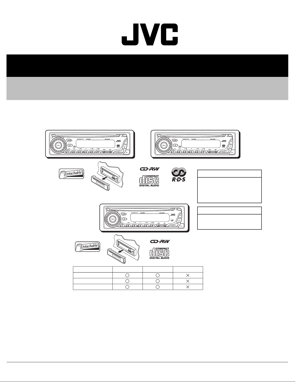
KD-G201, KD-G202, KD-G207
KD-G201
KD-G207
KD-G202
KD-G201,KD-G202
Area suffix
E ----------- Continental Europe
EX --------------- Central Europe
KD-G207
Area suffix
EE --------- Russian Federation
KD-G201 E KD-G202 E/EX
STEERING CABLE
RDS
LINE OUT
KD-G207 EE/EX
TABLE OF CONTENTS
1 PRECAUTION. . . . . . . . . . . . . . . . . . . . . . . . . . . . . . . . . . . . . . . . . . . . . . . . . . . . . . . . . . . . . . . . . . . . . . . . . 1-4
2 SPECIFIC SERVICE INSTRUCTIONS. . . . . . . . . . . . . . . . . . . . . . . . . . . . . . . . . . . . . . . . . . . . . . . . . . . . . . 1-6
3 DISASSEMBLY . . . . . . . . . . . . . . . . . . . . . . . . . . . . . . . . . . . . . . . . . . . . . . . . . . . . . . . . . . . . . . . . . . . . . . . 1-7
4 ADJUSTMENT . . . . . . . . . . . . . . . . . . . . . . . . . . . . . . . . . . . . . . . . . . . . . . . . . . . . . . . . . . . . . . . . . . . . . . . 1-25
5 TROUBLE SHOOTING. . . . . . . . . . . . . . . . . . . . . . . . . . . . . . . . . . . . . . . . . . . . . . . . . . . . . . . . . . . . . . . . . 1-26
COPYRIGHT © 2004 VICTOR COMPANY OF JAPAN, LIMITED
No.MA039
2004/1
Page 2

SPECIFICATION
KD-G202/KD-G201
AUDIO AMPLIFIER SECTION
Maximum Power Output Front 50 W per channel
Rear 50 W per channel
Continuous Power Output (RMS) Front 19 W per channel into 4 Ω, 40 Hz to 20 000 Hz at no more
than 0.8% total harmonic distortion.
Rear 19 W per channel into 4 Ω, 40 Hz to 20 000 Hz at no more
than 0.8% total harmonic distortion.
Load Impedance 4 Ω (4 Ω to 8 Ω allowance)
Tone Control Range Bass ±10 dB at 100 Hz
Treble ±10 dB at 10 kHz
Frequency Response 40 Hz to 20 000 Hz
Signal-to-Noise Ratio 70 dB
Line-Out Level/Impedance 2.0 V/20 kΩ load (full scale)
Output Impedance 1 kΩ
TUNER SECTION
Frequency Range FM 87.5 MHz to 108.0 MHz
AM (MW) 522 kHz to 1 620 kHz
(LW) 144 kHz to 279 kHz
[FM Tuner] Usable Sensitivity 11.3 dBf (1.0 µV/75 Ω)
50 dB Quieting Sensitivity 16.3 dBf (1.8 µV/75 Ω)
Alternate Channel Selectivity (400 kHz) 65 dB
Frequency Response 40 Hz to 15 000 Hz
Stereo Separation 30 dB
Capture Ratio 1.5 dB
[MW Tuner] Sensitivity 20 µV
Selectivity 35 dB
[LW Tuner] Selectivity 50 µV
CD PLAYER SECTION
Type Compact disc player
Signal Detection System Non-contact optical pickup (semiconductor laser)
Number of channels 2 channels (stereo)
Frequency Response 5 Hz to 20 000 Hz
Dynamic Range 96 dB
Signal-to-Noise Ratio 98 dB
Wow and Flutter Less than measurable limit
GENERAL
Power Requirement Operating Voltage DC 14.4 V (11 V to 16 V allowance)
Grounding System Negative ground
Allowable Operating Temperature 0ºC to +40ºC
Dimensions (W × H × D) Installation Size (approx.) 182 mm × 52 mm × 150 mm
Panel Size (approx.) 188 mm × 58 mm × 11 mm
Mass (approx.) 1.3 kg (excluding accessories)
Design and specifications are subject to change without notice.
1-2 (No.MA039)
Page 3

KD-G207
AUDIO AMPLIFIER SECTION
Maximum Power Output Front 50 W per channel
Rear 50 W per channel
Continuous Power Output (RMS) Front 19 W per channel into 4 Ω, 40 Hz to 20 000 Hz at no more
than 0.8% total harmonic distortion.
Rear 19 W per channel into 4 Ω, 40 Hz to 20 000 Hz at no more
than 0.8% total harmonic distortion.
Load Impedance 4 Ω (4 Ω to 8 Ω allowance)
Tone Control Range Bass ±10 dB at 100 Hz
Treble ±10 dB at 10 kHz
Frequency Response 40 Hz to 20 000 Hz
Signal-to-Noise Ratio 70 dB
Line-Out Level/Impedance 2.0 V/20 kΩ load (full scale)
Output Impedance 1 kΩ
TUNER SECTION
Frequency Range FM1/FM2 87.5 MHz to 108.0 MHz
FM3 65.00 MHz to 74.00 MHz
AM (MW) 522 kHz to 1 620 kHz
(LW) 144 kHz to 279 kHz
[FM Tuner] Usable Sensitivity 11.3 dBf (1.0 µV/75 Ω)
50 dB Quieting Sensitivity 16.3 dBf (1.8 µV/75 Ω)
Alternate Channel Selectivity (400 kHz) 65 dB
Frequency Response 40 Hz to 15 000 Hz
Stereo Separation 30 dB
Capture Ratio 1.5 dB
[MW Tuner] Sensitivity 20 µV
Selectivity 35 dB
[LW Tuner] Selectivity 50 µV
CD PLAYER SECTION
Type Compact disc player
Signal Detection System Non-contact optical pickup (semiconductor laser)
Number of channels 2 channels (stereo)
Frequency Response 5 Hz to 20 000 Hz
Dynamic Range 96 dB
Signal-to-Noise Ratio 98 dB
Wow and Flutter Less than measurable limit
GENERAL
Power Requirement Operating Voltage DC 14.4 V (11 V to 16 V allowance)
Grounding System Negative ground
Allowable Operating Temperature 0ºC to +40ºC
Dimensions (W × H × D) Installation Size (approx.) 182 mm × 52 mm × 150 mm
Panel Size (approx.) 188 mm × 58 mm × 11 mm
Mass (approx.) 1.3 kg (excluding accessories)
Design and specifications are subject to change without notice.
(No.MA039)1-3
Page 4
1.1 Safety Precautions
SECTION 1
PRECAUTION
!
!
Burrs formed during molding may be left over on some parts of the chassis. Therefore,
pay attention to such burrs in the case of preforming repair of this system.
Please use enough caution not to see the beam directly or touch it in case of an
adjustment or operation check.
1-4 (No.MA039)
Page 5
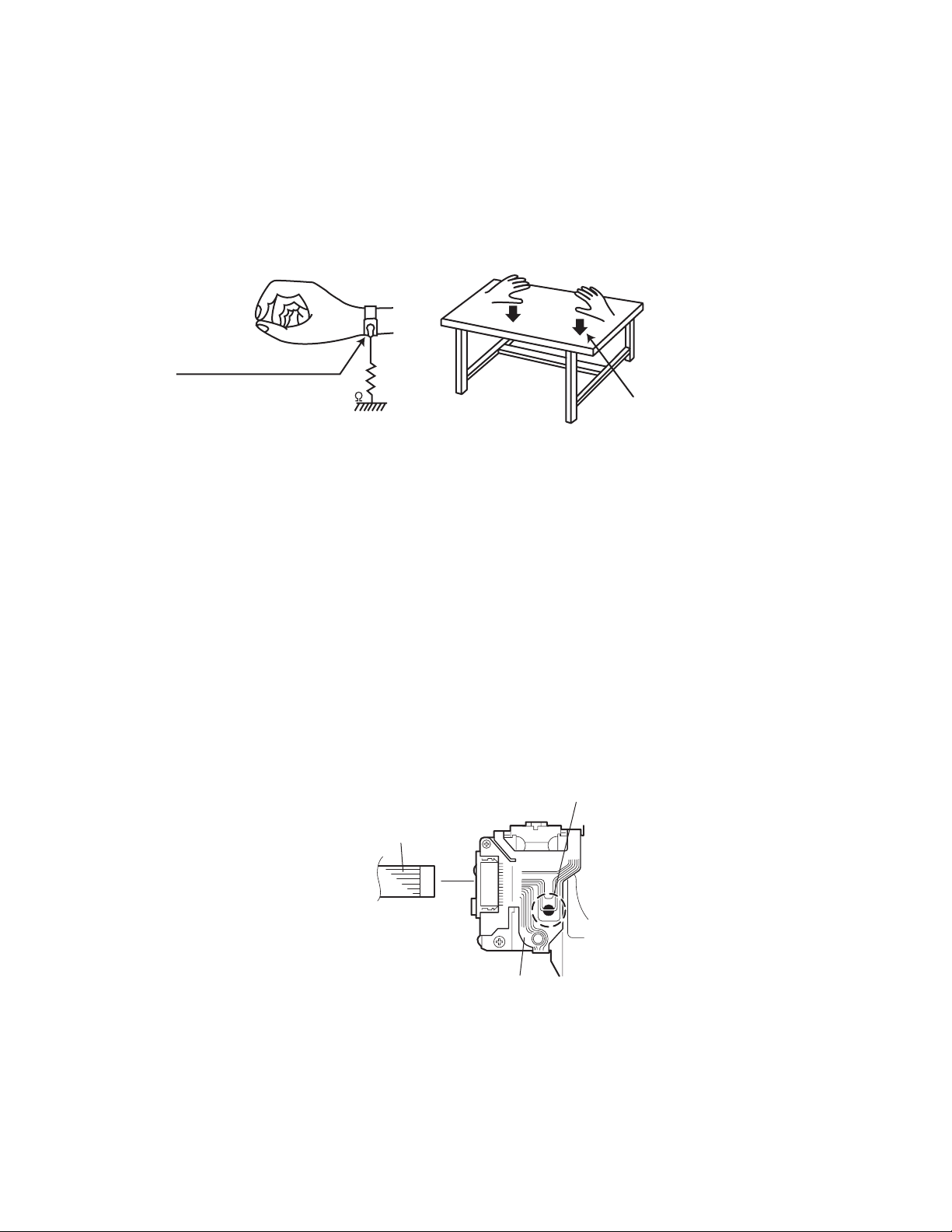
1.2 Preventing static electricity
Electrostatic discharge (ESD), which occurs when static electricity stored in the body, fabric, etc. is discharged, can destroy the laser
diode in the traverse unit (optical pickup). Take care to prevent this when performing repairs.
1.2.1 Grounding to prevent damage by static electricity
Static electricity in the work area can destroy the optical pickup (laser diode) in devices such as CD players.
Be careful to use proper grounding in the area where repairs are being performed.
(1) Ground the workbench
Ground the workbench by laying conductive material (such as a conducti ve sheet) or an iron plate over it before placing the
traverse unit (optical pickup) on it.
(2) Ground yourself
Use an anti-static wrist strap to release any static electricity built up in your body.
(caption)
Anti-static wrist strap
1M
Conductive material
(conductive sheet) or iron plate
(3) Handling the optical pickup
• In order to mainta in quality during transport and b efore installation, both sid es of the laser diode on th e replacement optica l
pickup are shorted. After replacement, return the shorted parts to their original condition.
(Refer to the text.)
• Do not use a tester to check the condition of the laser diode in the optical pickup. The tester's internal power source can easily
destroy the laser diode.
1.3 Handling the traverse unit (optical pickup)
(1) Do not subject the traverse unit (optical pickup) to strong shocks, as it is a sensitive, complex unit.
(2) Cut off the shorted part of the flexible cable using nippers, etc. after replacing the optical pickup. For specific details, refer to the
replacement procedure in the text. Remove the anti-static pin when replacing the traverse unit. Be careful not to take too long a
time when attaching it to the connector.
(3) Handle the flexible cable carefully as it may break when subjected to strong force.
(4) It is not possible to adjust the semi-fixed resistor that adjusts the laser power. Do not turn it.
1.4 Attention when traverse unit is decomposed
*Please refer to "Disassembly method" in the text for the CD pickup unit.
• Apply solder to the short land be fore the flexible wire is disconnected from the connector on the CD pickup unit.
(If the flexible wire is disconnected without applying solder, the CDpickup may be destroyed by static electricity.)
• In the assembly, be sure to remove solder from the short land after connecting the flexible wire.
Short-circuit point
(Soldering)
Flexible wire
Pickup
(No.MA039)1-5
Page 6

SECTION 2
SPECIFIC SERVICE INSTRUCTIONS
This service manual does not describe SPECIFIC SERVICE INSTRUCTIONS.
1-6 (No.MA039)
Page 7
SECTION 3
DISASSEMBLY
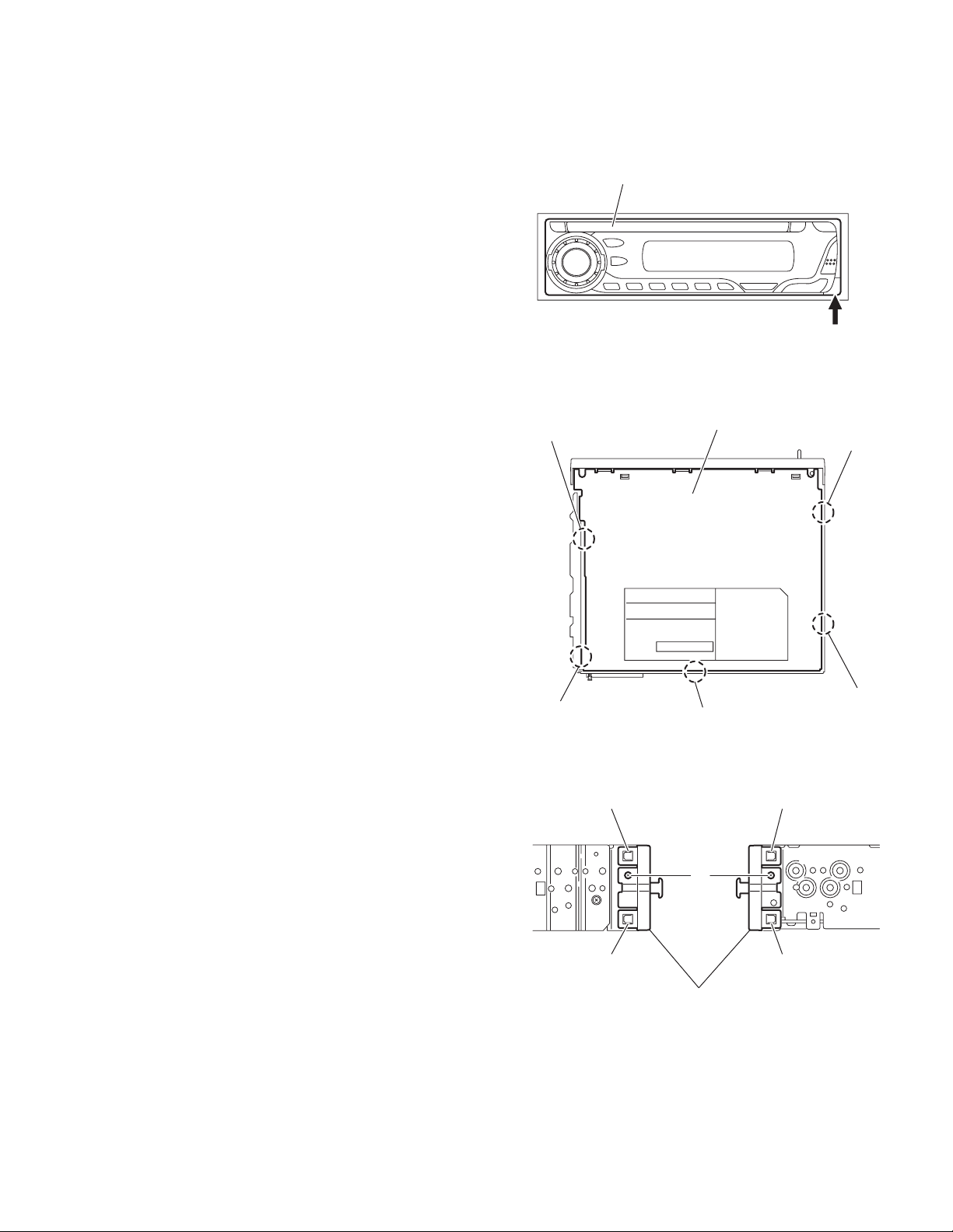
3.1 Main body
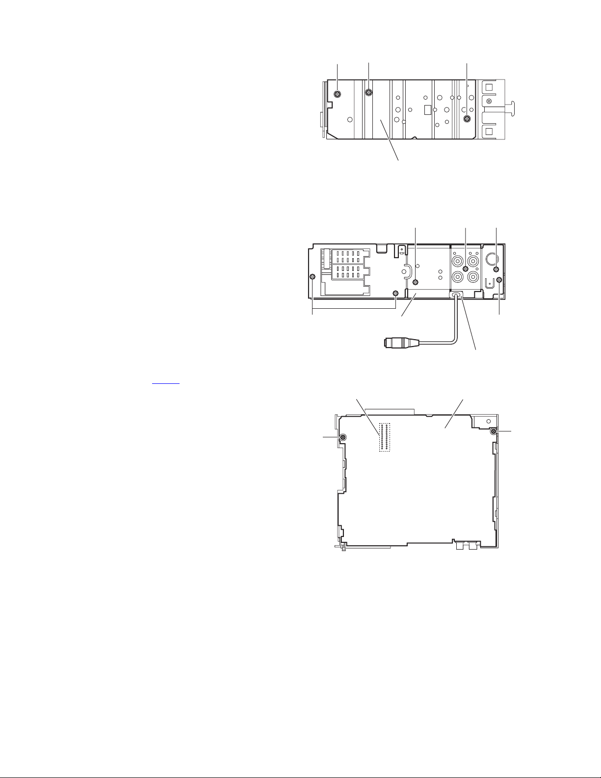
3.1.1 Removing the front panel assembly
(See Fig.1)
(1) Push the detach button in the lower ri ght part of the front
panel assembly and remove the front panel assembly.
3.1.2 Removing the bottom cover
(See Fig.2)
(1) From the bottom side of the mai n body, release the two
joints a, two joints b and joint c.
CAUTION:
Do not damage the main board when releasing the joints using
a screwdriver.
Front panel assembly
Joint a
Detach button
Fig.1
Bottom cover
Joint b
3.1.3 Removing the front chassis assembly
(See Fig.3)
• Prior to performing the following procedures, remove the front
panel assembly and bottom cover.
(1) Remove the two screws A on the both sides of the main
body.
(2) Release the two joints d and two joints e on the both sides
of the main body, then remove the front chassis assembly
toward the front.
Joint a
Joint c
Fig.2
Joint d Joint e
A
Joint d
Front chassis
Fig.3
Joint e
Joint b
(No.MA039)1-7
Page 8
3.1.4 Removing the side panel
(See Fig.4)
• Prior to performin g the following procedure, remove the front
panel assembly as required.
(1) Remove the screw B and two scre ws C attaching the heat
sink on the left side of the main body, and remove the side
panel.
3.1.5 Removing the rear bracket
(See Fig.5)
• Prior to performing the following procedure, remove the bottom
cover.
(1) Remove the three screws D, screw E and two screws F at-
taching the rear bracket on the back side of the main body.
(2) Remove the rear bracket.
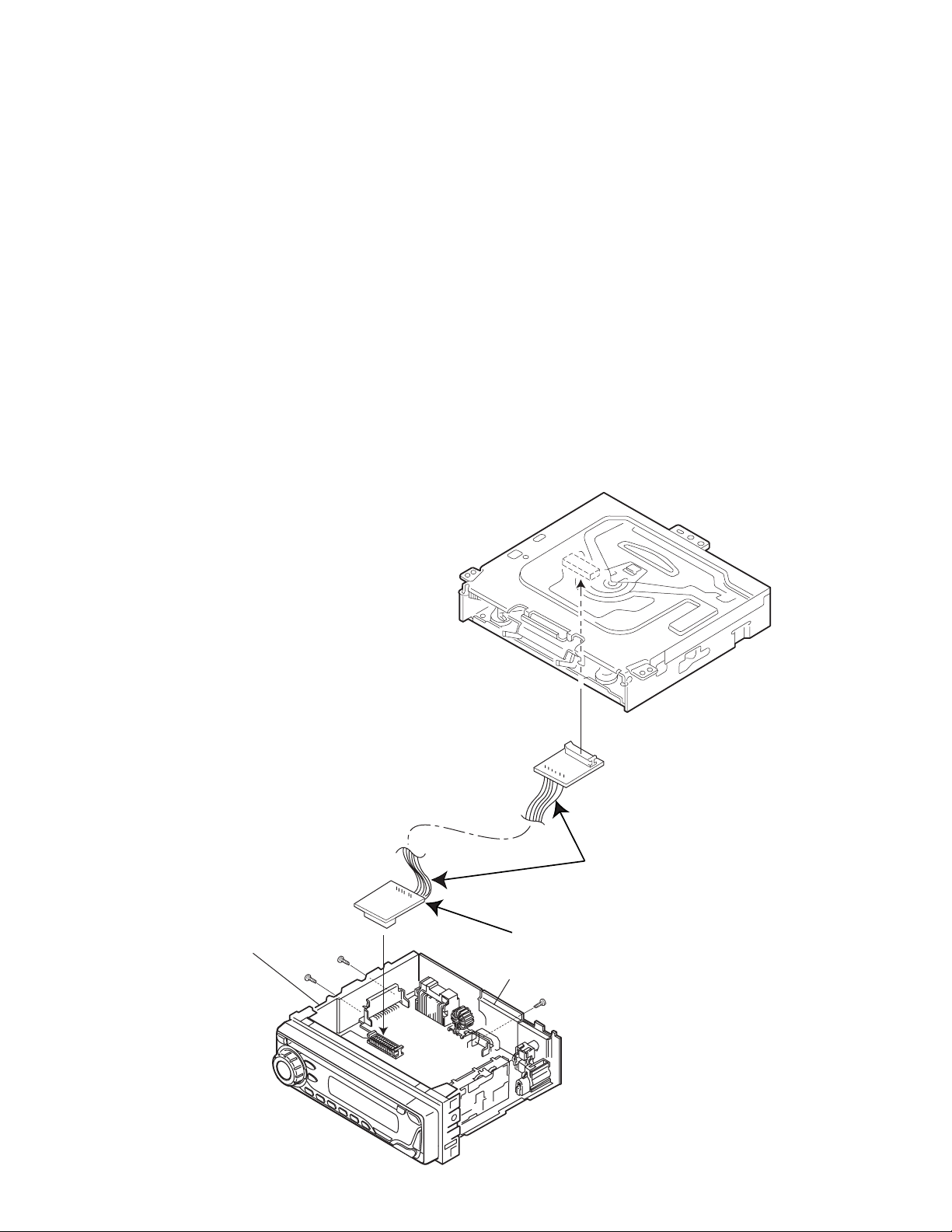
3.1.6 Removing the main board
(See Figs.5 and 6)
• Prior to performing the following procedures, remove the front
panel assembly, bottom cover, front chassis assembly and
side panel.
• Remove the front chassis assembly as required.
(1) Remove the three screws D attaching the rear bracket on
the back side of the main body. (See fig.5.)
(2) From the bottom side of the main bo dy, remove the two
screws H attaching the main board. (See fig.6.)
(3) Disconnect the connector CN501
assembly and remove the main board. (See fig.6.)
Reference:
• Remove the rear bracket from the main body as required.(See "3.1.5 Removing the rear bracket ".)
• During reas sembly, before fixing the rear bracket onto the
main body, insert the steering remote into the slot. (For
G201 and G202)
from the CD mechanism
D
G
C
CN501
B
Side panel
Rear bracket
C
Fig.4
E
Insert the steering remote
into the slot.
Fig.5
Main board
FF
D
G
1-8 (No.MA039)
Fig.6
Page 9
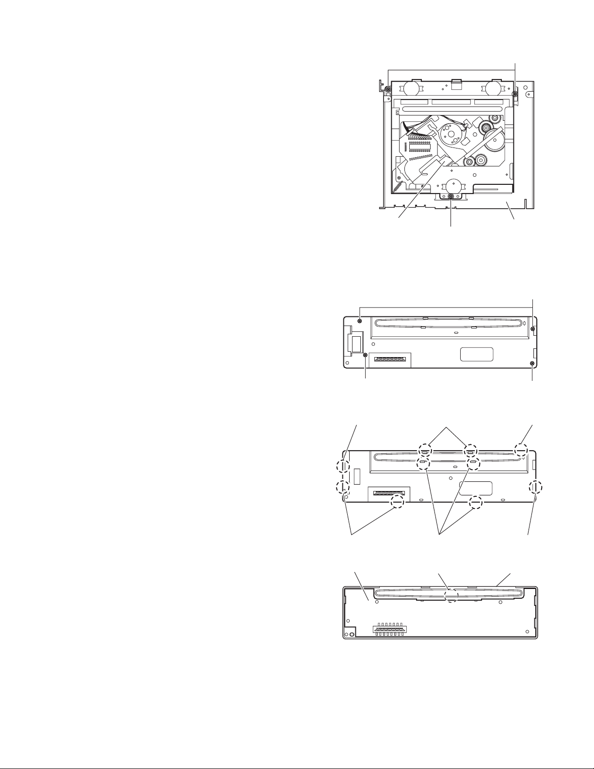
3.1.7 Removing the CD mechanism assembly
f
(See Fig.7)
• Prior to performi ng the following procedure, remove the front
panel assembly, bottom cover, front chassis assembly, side
panel, rear bracket, main board and CD mechanism board.
(1) Remove the three screws H attaching the top chassis.
(2) Take out the CD mechanism assembly.
(3)
H
3.1.8 Removing the front board
(See Figs.8 to 10)
• Prior to performi ng the following procedure, remove the front
panel assembly.
(1) Remove the four screws J on the back side of the front pan-
el assembly. (See Fig.8.)
(2) Release the ten joints f attaching the rear cover to the front
panel assembly. (See Fig.9.)
(3) Release the joint g and take out the front board. (See
Fig.10.)
CD mechanism assembly
Fig.7
J
Fig.8
Joint f Joints f
Top chassis
H
J
J
Joints
Joints f
Front board
Joints f
Fig.9
Joint g
Fig.10
Joint f
Front panel assembly
(No.MA039)1-9
Page 10
3.2 CD Mechanism Assembly
A
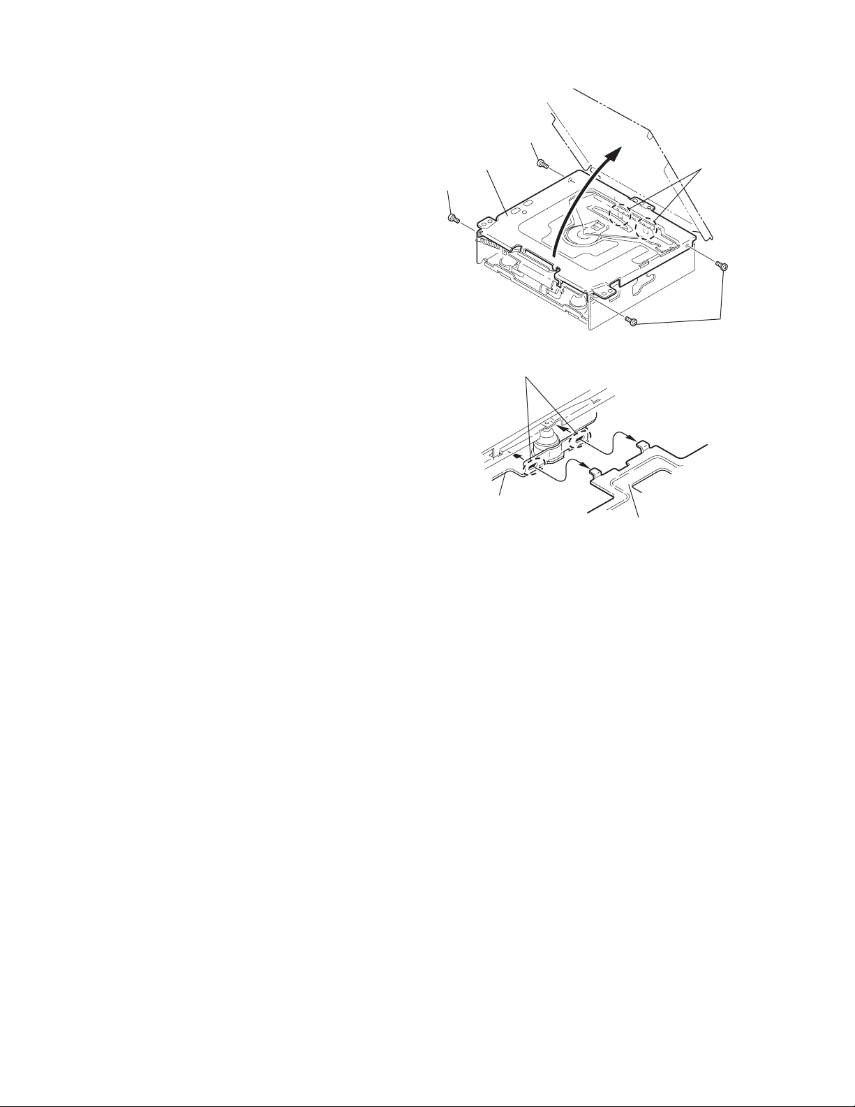
3.2.1 Removing the top cover
(See Figs.1 and 2)
(1) Remove the two screws A on the both side of the body.
(2) Lift the front side of the top cover and move the top cover
backward to release the two joints a.
Top cover
Joints a
A
Joints a
A
Fig.1
Fig.2
Top cover
1-10 (No.MA039)
Page 11
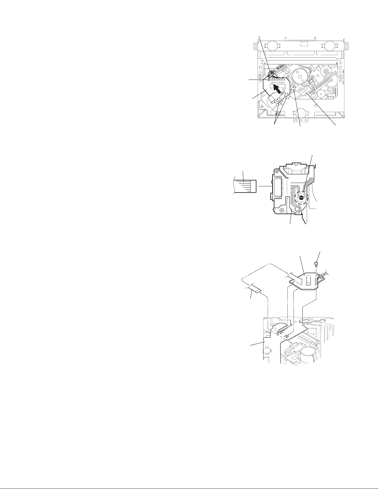
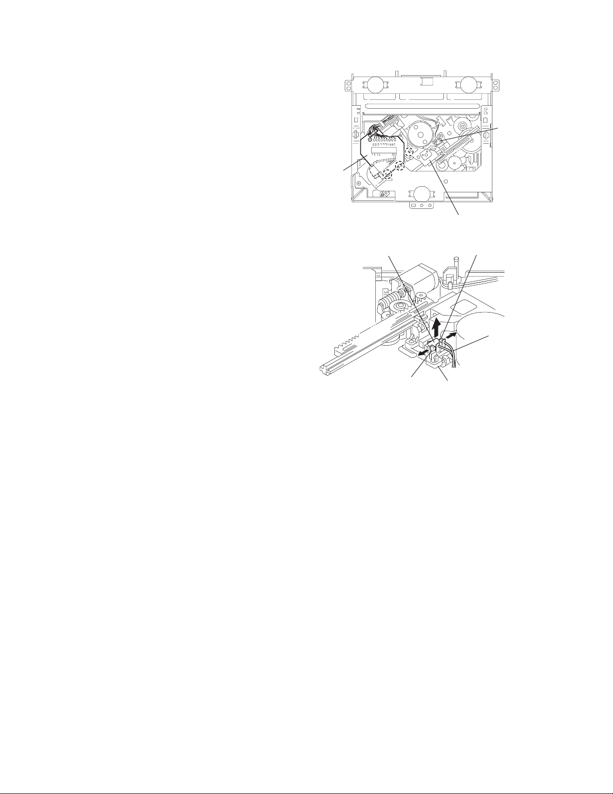
3.2.2 Removing the connector board
(See Figs.3 to 5)
CAUTION:
Before disconnecting the flexible wire from the pickup, solder
the short-circuit point on the pickup. No observance of this instruction may cause damage of the pickup.
(1) Remove the screw B fixing the connector board.
(2) Solder the short-circuit point on the connector board.
(3) Disconnect the flexible wire from the pickup.
(4) Move the connector board in the direction of the arrow to
release the two joints b.
(5) Unsolder the wire on the connector board if necessary.
CAUTION:
Unsolder the short-circuit point after reassembling.
B
Connector board
Flexible wire
Wires
Joints b
Short-circuit point
Fig.3
Short-circuit point
(Soldering)
Pickup
Flexible wire
Frame
Pickup
Fig.4
B
Connector board
Fig.5
(No.MA039)1-11
Page 12
3.2.3 Removing the DET switch
(See Figs.6 and 7)
(1) Extend the two tabs c of the feed sw. holder and pull out
the switch.
(2) Unsolder the DET switch wire if necessary.
Connector
board
DET switch
DET switch
Pickup
Fig.6
Tab c
DET switch wire
Tab c
Feed sw. holder
Fig.7
1-12 (No.MA039)
Page 13
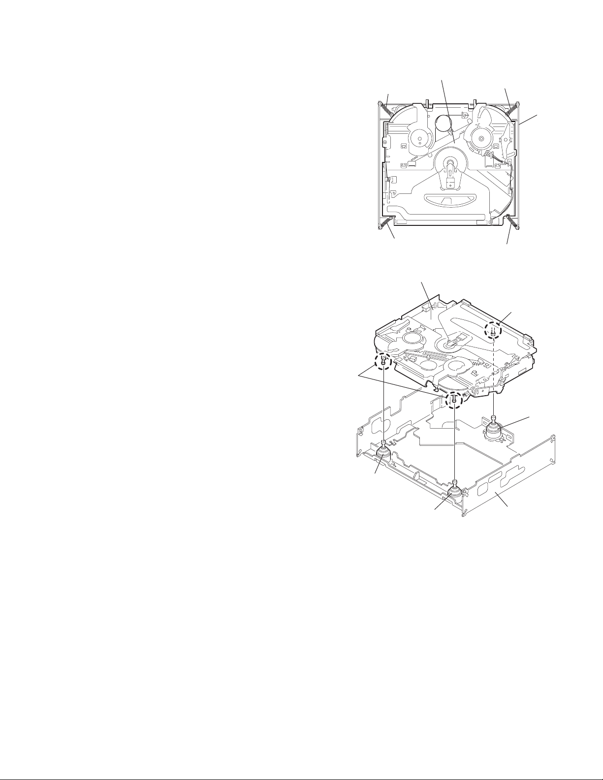
3.2.4 Removing the chassis unit
r
(See Figs.8 and 9)
• Prior to perfo rming the following procedure, remove the top
cover and connector board.
(1) Remove the two suspensi on springs (L) an d (R) attaching
the chassis unit to the frame.
CAUTION:
• The shape of the suspension spring (L) and (R) are different. Handle them with care.
• When reassembling, make su re that the three shafts
on the underside of the chassis unit are inserted to the
dampers certainly.
Suspension spring (R)
Chassis unit
Suspension spring (L)
Frame
Suspension spring (R)
Chassis unit
Shafts
Damper
Damper
Suspension spring (L)
Fig.8
Shaft
Dampe
Frame
Fig.9
(No.MA039)1-13
Page 14
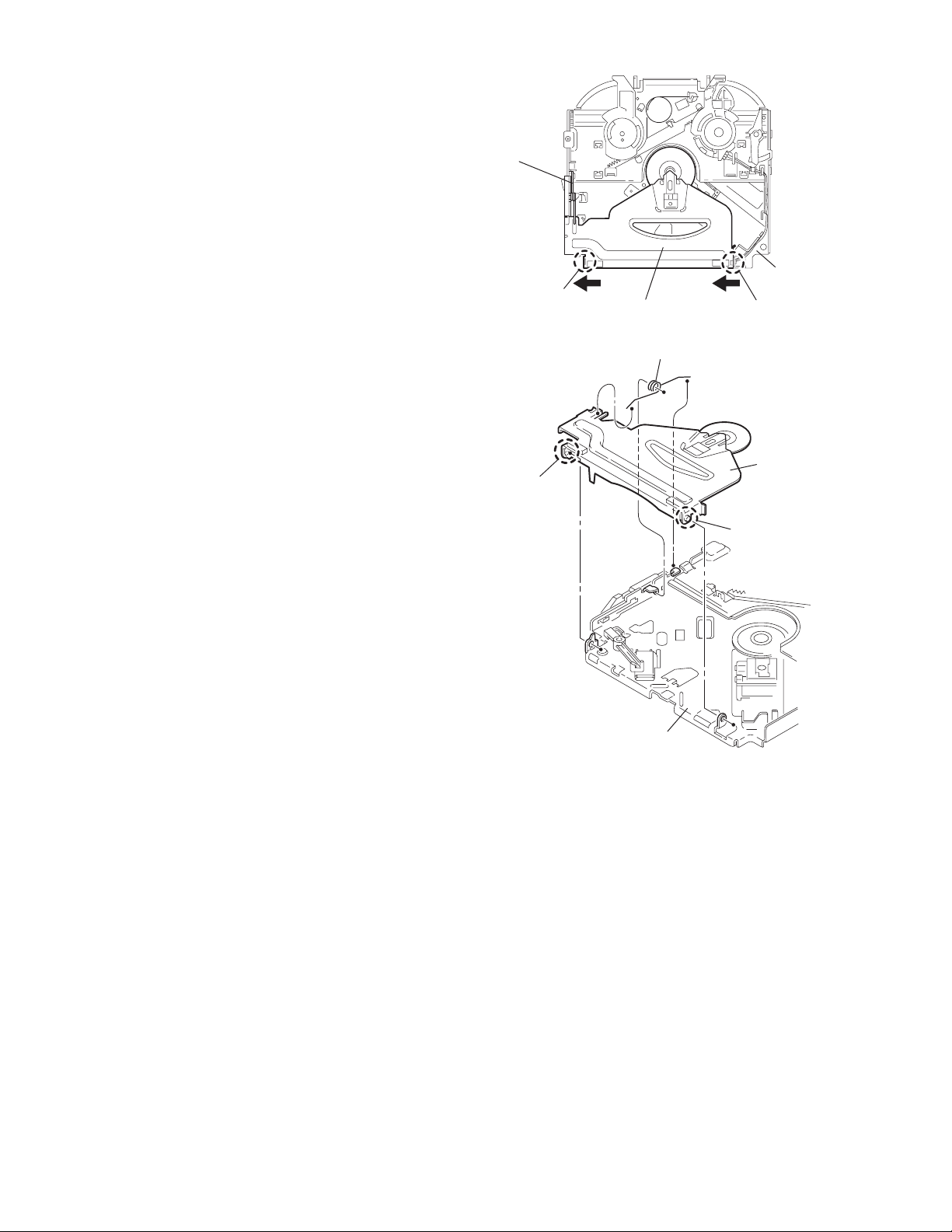
3.2.5 Removing the clamper assembly
(See Figs.10 and 11)
• Prior to performing the follow ing procedure, remove the top
cover.
(1) Remove the clamper arm spring.
(2) Move the clamper assembly in the direction of the arrow to
release the two joints d.
Clamper arm
spring
Joint d
Joint d
Clamper assembly
Fig.10
Clamper arm spring
Chassis rivet
assembly
Joint d
Clamper
assembly
Chassis rivet assembly
Fig.11
Joint d
1-14 (No.MA039)
Page 15
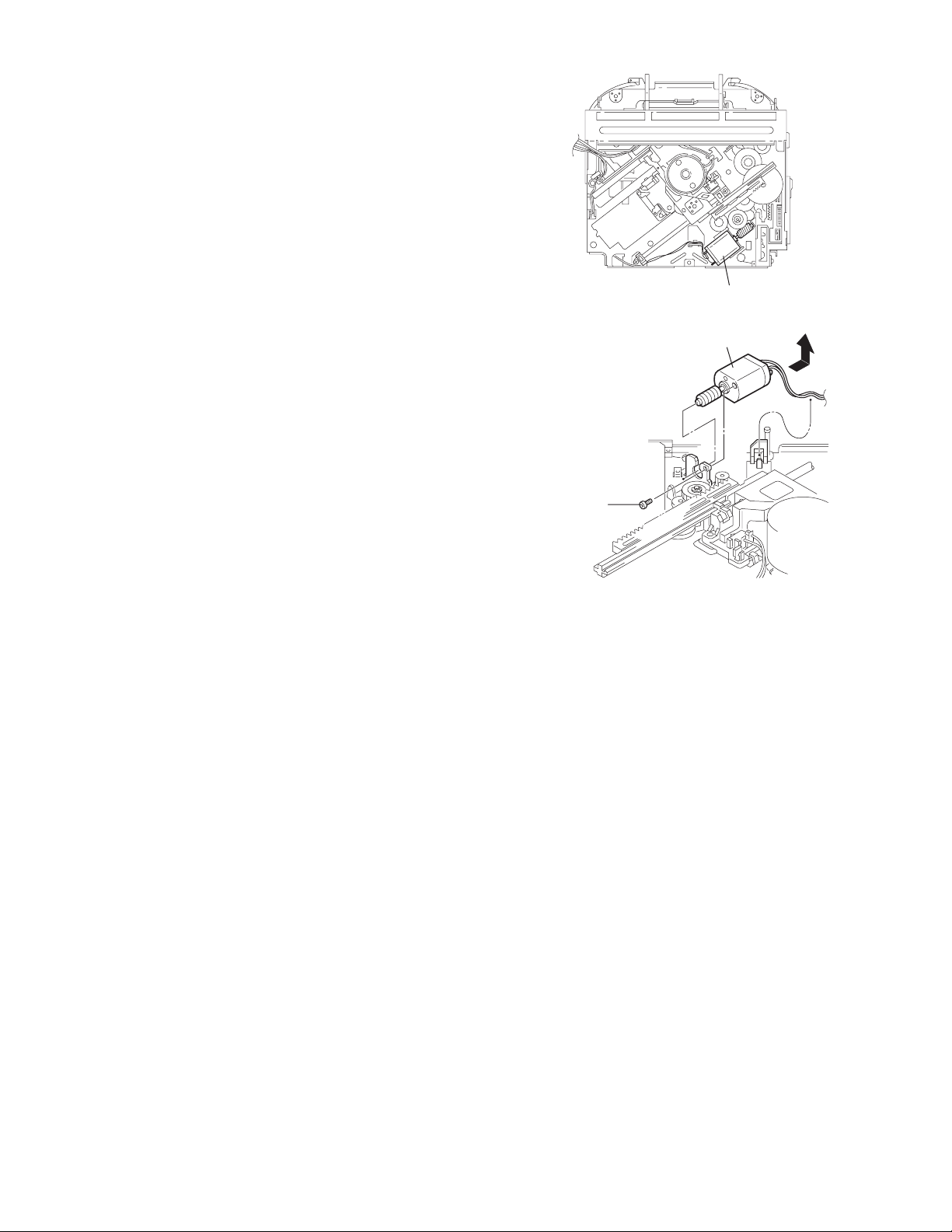
3.2.6 Removing the loading / feed motor assembly
(See Figs.12 and 13)
• Prior to perfo rming the following procedure, remove the top
cover, connector board and chassis unit.
(1) Remove the screw C and move the loa ding / feed motor
assembly in the direction of the arrow to remove it from the
chassis rivet assembly.
(2) Disconnect the wire from the loading / feed motor assembly
if necessary.
CAUTION:
When reassembling, connect the wire from the loading /
feed motor assembly to the flame as shown in Fig.12.
Loading / feed motor assembly
Fig.12
Loading / feed motor assembly
C
Fig.13
(No.MA039)1-15
Page 16
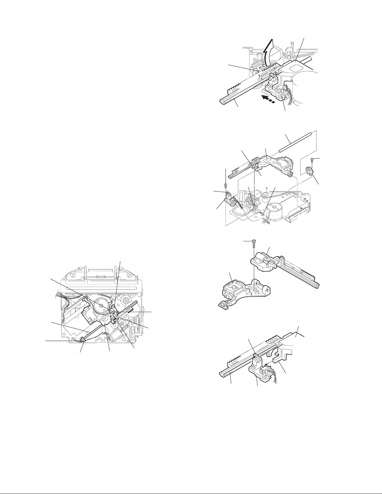
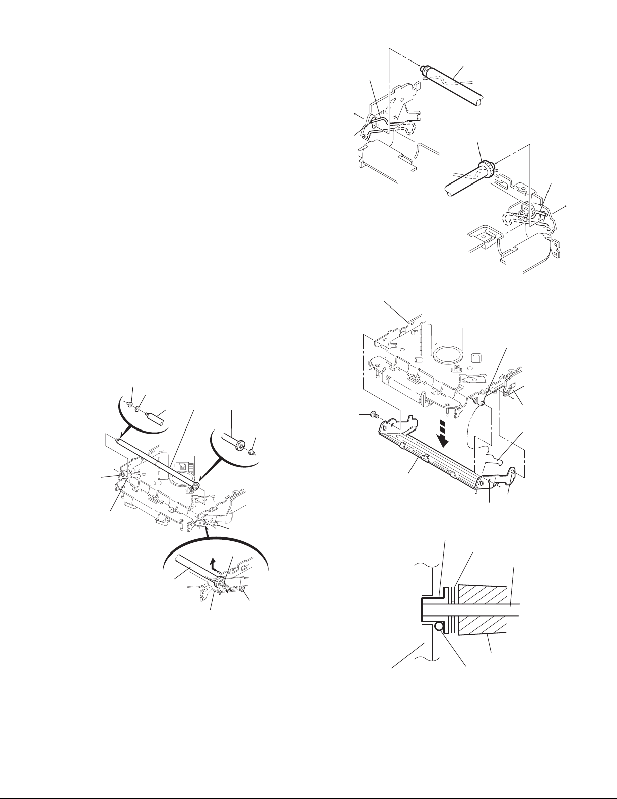
3.2.7 Removing the pickup unit
(See Figs.14 to 18)
• Prior to performing the follow ing procedure, remove the top
cover, connector board and chassis unit.
(1) Remove the screw D and pull out the pu. shaft holder from
the pu. shaft.
(2) Remove the screw E attaching the feed sw. holder.
(3) Move the part e of the pickup unit upward with the pu. shaft
and the feed sw. holder, then release the joint f of the feed
sw. holder in the direction of the arrow. The joint g of the
pickup unit and the feed rack is released, and the feed sw.
holder comes off.
(4) Remove the pu. shaft from the pickup unit.
(5) Remove the screw F attaching the feed rack to the pickup
unit.
3.2.8 Reattaching the pickup unit
(See Figs.14 to 17)
(1) Reattach the feed rack to the pickup unit using the screw F.
(2) Reattach the feed sw. holder to the feed rack wh ile setting
the joint g to the slot of the feed rack and setting the part f
of the feed rack to the switch of the feed sw. holder correctly.
(3) As the feed sw. holder is temporarily attached to the pickup
unit, set to the gear of the joint g and to the bending part of
the chassis (joint h) at a time.
CAUTION:
Make sure that the part i on the underside of the feed
rack is certainly inserted to the slot j of the change lock
lever.
(4) Reattach the feed sw. holder using the screw E.
(5) Reattach the pu. shaft to the pickup unit. Reattach the pu.
shaft holder to the pu. shaft using the screw D.
Feed sw. holder
Joint f
Joint g
Feed sw.
holder
Part e
Feed rack
Part i
E
Pickup unit
Slot j
F
Fig.15
Pu. shaft
Pickup unit
Joint f
Joint h
Fig.16
Feed rack
Pickup unit
Feed sw. holder
D
Pu. shaft
holder
Pu. shaft
D
Pu. shaft holder
1-16 (No.MA039)
Pickup unit
Fig.14
Part e
E
Joint g
Feed rack
Fig.17
Pickup unit
Joint g
Joint f
Feed sw. holder
Fig.18
Page 17
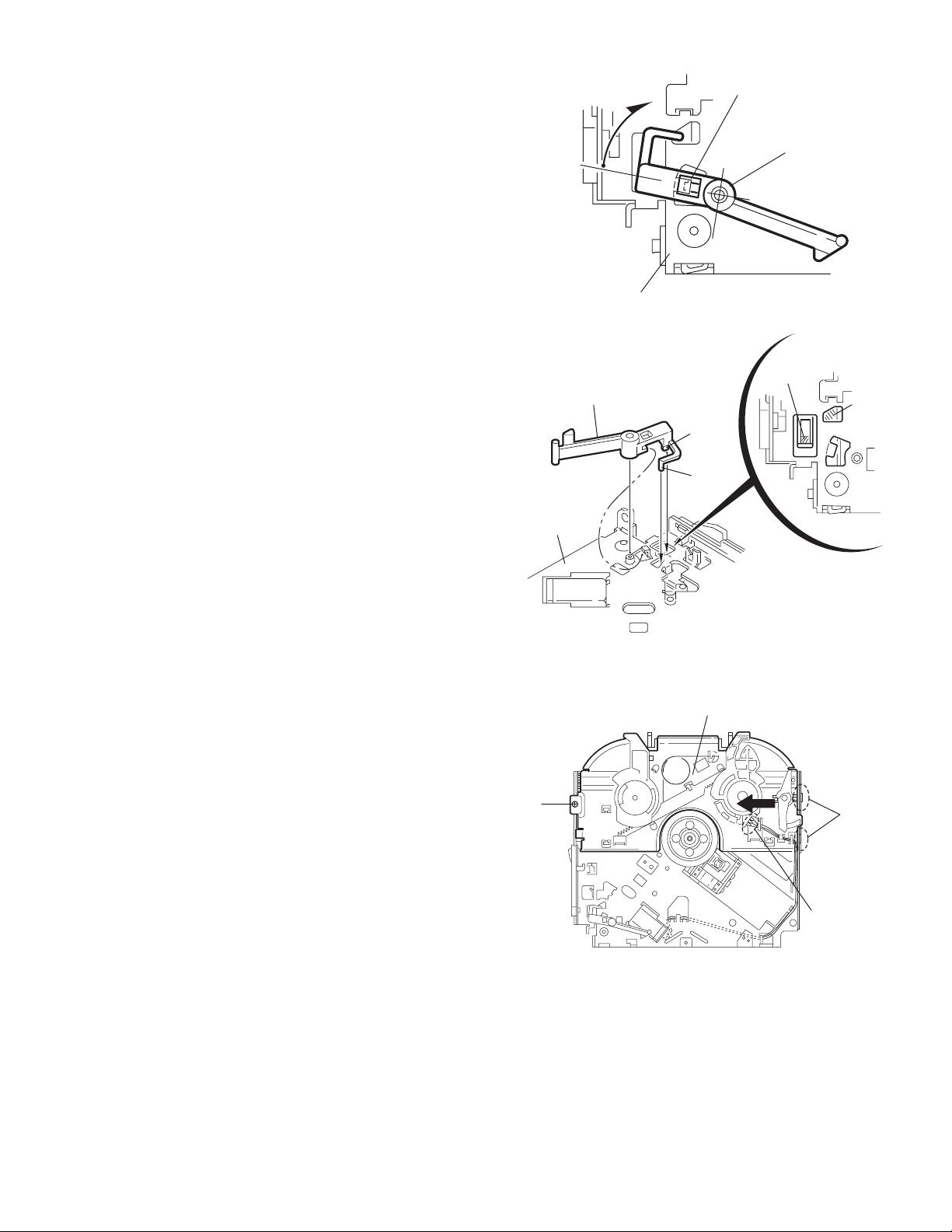
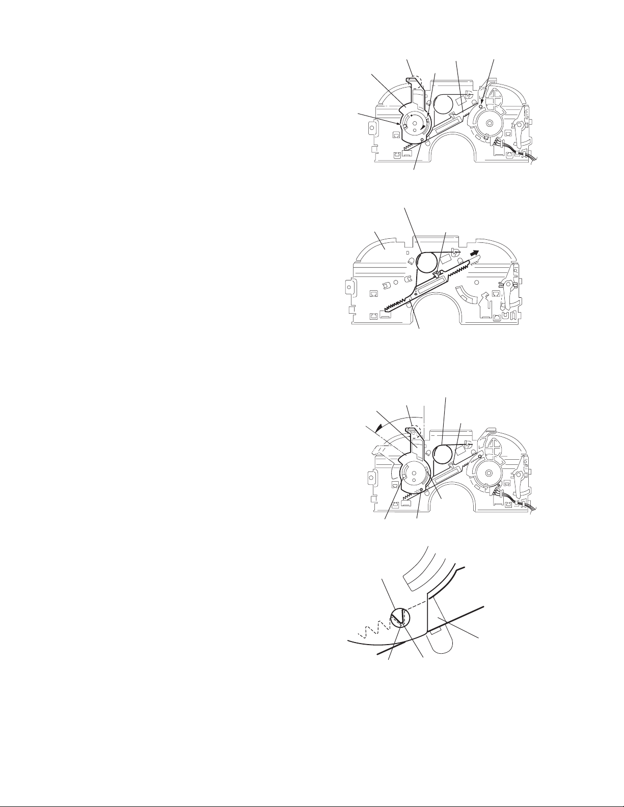
3.2.9 Removing the trigger arm
r
(See Figs.19 and 20)
• Prior to perfo rming the following procedure, remove the top
cover, connector board and clamper unit.
(1) Turn the trigger arm in the direction of the arrow to release
the joint k and pull out upward.
CAUTION:
When reassembling, insert the part m and n of the trigger
arm into the part p and q at the slot of the chassis rivet
assembly respectively and join the joint k at a time.
Chassis rivet assembly
Trigger arm
Chassis rivet
assembly
Joint k
Trigger arm
Fig.19
Part p
Part q
Part m
Part n
3.2.10 Removing the top plate assembly
(See Fig.21)
• Prior to perfo rming the following procedure, remove the top
cover, connector board, chassis unit, and clamper assembly.
(1) Remove the screw H.
(2) Move the top plate assembly in the direction of the arrow to
release the two joints r.
(3) Unsolder the wire marked s if necessary.
H
Fig.20
Top plate assembly
Joints
s
Fig.21
(No.MA039)1-17
Page 18
3.2.11 Removing the mode sw. / select lock arm
(See Figs.22 and 23)
• Prior to performing the follow ing procedure, remove the top
plate assembly.
(1) Bring up the mode sw. to release from the link plate (joint t)
and turn in the direction of the arrow to release the joint u.
(2) Unsolder the wire of the mode sw. marked s if necessary.
(3) Turn the select lock arm in the direction of the arrow to re-
lease the two joints v.
(4) The select lock arm spring comes off the select lock arm at
the same time.
Top plate
Link plate
Joint u
Joint t
s
Fig.22
Select lock arm
Select lock arm
Mode sw.
Select lock arm
Top plate
Hook w
Select lock
arm spring
Link plate
Joints v
Fig.23
1-18 (No.MA039)
Page 19
3.2.12 Reassembling the mode sw. / select lock arm
(See Figs.24 to 26)
REFERENCE:
Reverse the above removing procedure.
(1) Reattach the select lock arm spring to the top plate and set
the shorter end of the select lock arm spring to the hook w
on the top plate.
(2) Set the other longer end of the select lock arm spring to the
boss x on the underside of the select lock arm, and join the
select lock arm to the slots (joint v). Turn the select lock
arm as shown in the figure.
(3) Reattach the mode sw. while setting th e part t to the first
peak of the link plate gear, and join the joint u.
CAUTION:
When reattaching the mode sw., check if the points y and
z are correctly fitted and if each part operates properly.
Select lock arm spring
Hook w
Joint v
Joint v
Select lock arm
Boss x
Fig.24
Joint t
Point y
Link plate
Point z
Link plate
Fig.25
Mode sw.
Select
lock arm
Joint t
Joint u
Fig.26
(No.MA039)1-19
Page 20
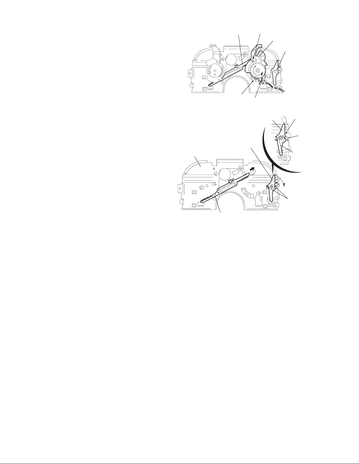
3.2.13 Removing the select arm R / link plate
(See Figs.27 and 28)
• Prior to performing the follow ing procedure, remove the top
plate assembly.
(1) Bring up the select arm R to release from the link plate
(joint a') and turn as shown in the figure to release the two
joints b' and joint c'.
(2) Move the link plate in the direction of the arrow to release
the joint d'. Remove the link plate spring at the same time.
REFERENCE:
Before removing the link plate, remove the mode sw..
Select arm R
Joint b'
Link plate spring
Joint c'
Joint a'
Link plate
Joint b'
Fig.27
Joint r
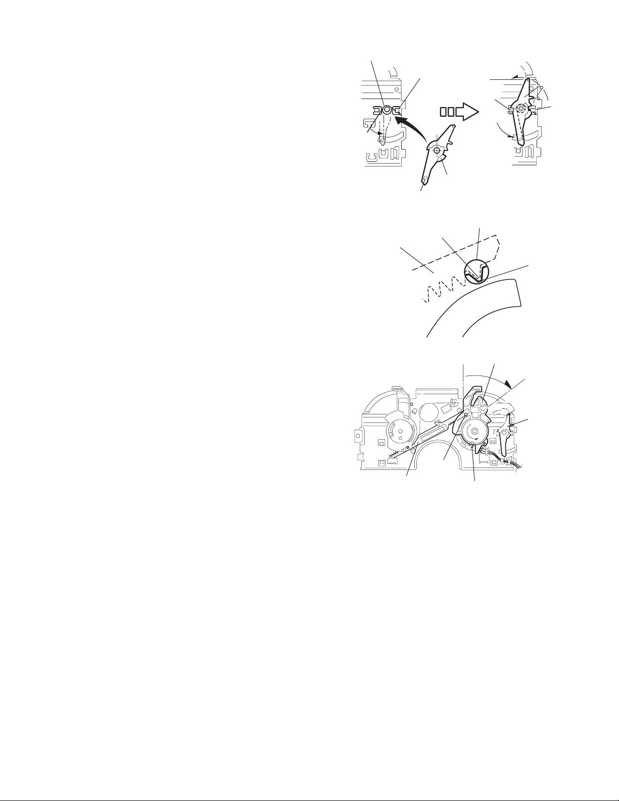
3.2.14 Reattaching the Select arm R / link plate
(See Figs.29 and 30)
REFERENCE:
Reverse the above removing procedure.
(1) Reattach the link plate spring.
(2) Reattach the link plate to th e lin k plate sprin g whil e joi ning
them at joint d'.
(3) Reattach the joint a' of the select arm R to the first peak of
the link plate while joining the two joints b' with the slots.
Then turn the select arm R as shown in the figure. The top
plate is joined to the joint c'.
CAUTION:
When reattaching the select arm R, check if the points e'
and f' are correctly fitted and if each part operates properly.
Top plate
Select arm R
Joint b'
Joint d'
Link plate
Fig.28
Link plate spring
Joint c'
Joint d'
Joint b'
Joint a'
Fig.29
1-20 (No.MA039)
Joint a'
Point e'
Link plate
Point f'
Fig.30
Page 21
3.2.15 Removing the loading roller assembly
(See Figs.31 to 33)
• Prior to performing the following procedure, remove the
clamper assembly and top plate assembly.
(1) Push inward the loading roller assembly on the gear side
and detach it upward from the slot of the joint g' of the lock
arm rivet assembly.
(2) Detach the loading roller assembly from the slot of the joint
h' of the lock arm rivet assembly.
Roller guide
spring
Part k'
Loading roller assembly
Loading roller assembly
The roller guide comes off the gear section of the loading
roller assembly.
Remove the roller guide and the HL washer from the shaft
of the loading roller assembly.
(3) Remove the screw J attaching the lock arm rivet assembly.
(4) Push the shaft at the joint i' of the lock arm rivet assembly
inward to release the lock arm rivet assembly from the slot
of the L side plate.
(5) Extend the lock arm rivet assembly outward and release
the joint j' from the boss of the chassis rivet assembly. The
roller guide springs on both sides come off at the same
time.
CAUTION:
When reassembling, reattach the left and right roller
guide springs to the lock arm rivet assembly before reattaching the lock arm rivet assembly to the chassis rivet
assembly. Make sure to fit the part k' of the roller guide
spring inside of the roller guide. (Refer to Fig.34.)
Roller guide
HL washer
Loading roller assembly
Roller guide
Chassis rivet assembly
J
Roller guide
spring
Fig.32
Boss
L side plate
Roller guide spring
Joint h'
Roller guide spring
Loading roller assembly
Joint g'
Lock arm rivet assembly
Fig.31
Roller guide spring
Roller guide spring
Lock arm rivet assembly
Lock arm rivet assembly
Joint i'
Part j'
Fig.33
Roller guide
HL washer
Roller shaft assembly
Loading roller
Roller guide spring
Fig.34
(No.MA039)1-21
Page 22
3.2.16 Removing the loading gear 5, 6 and 7
(See Figs.35 and 36)
• Prior to performing the follow ing procedure, remove the top
cover, chassis unit, pickup unit and top plate assembly.
(1) Remove the screw K attaching the loading gear bracket.
The loading gear 6 and 7 come off the loading gear bracket.
(2) Pull out the loading gear 5.
K
Loading gear bracket
K
Loading gear 6
Loading gear 5
Loading gear 3
Fig.35
Loading gear bracket
Loading gear 5
Loading gear 6
Loading gear 7
Fig.36
1-22 (No.MA039)
Page 23
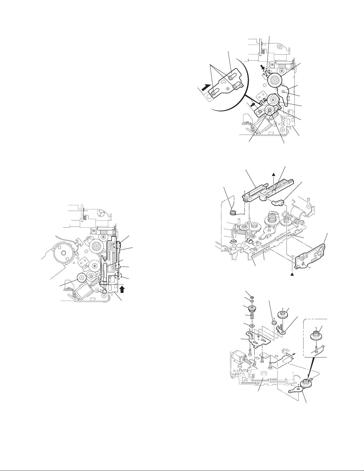
3.2.17 Removing the gears
(See Figs.37 to 40)
• Prior to perfo rming the following procedure, remove the top
cover, chassis unit, top plate assembly and pickup unit.
• Pull out the loading gear 3. (See Fig.35.)
(1) Pull out the feed gea r.
(2) Move the loading plate a ssemb ly in the d irection o f the ar-
row to release the L side plate from the two slots m' of the
chassis rivet assembly. (See Fig.37.)
(3) Detach the loading plate assemb ly upward from the chas-
sis rivet assembly while releasing the joint n'. Remove the
slide hook and loading plate spring from the loading plate
assembly.
(4) Pull out the loading gear 2 and remove the change lock le-
ver.
(5) Remove the E ring and washer attaching the changer gear
2.
(6) The changer gear 2, change gear spring and adjusting
washer come off.
(7) Remove the loading gear 1.
(8) Move the change plate rivet assembly in the direction of the
arrow to release from the three shafts of the chassis rivet
assembly upward. (See Fig.38.)
(9) Detach the loading gear plate rivet assembly from the shaft
of the chassis rivet assembly upward while releasing the
joint p'. (See Figs.38 and 40.)
(10) Pull out the loading gear 4.
Change plate
rivet assembly
Shafts
E ring
Loading plate assembly
Loading plate spring
Joint p'
Loading gear 4
Loading gear plate
rivet assembly
Shaft
Loading gear 2
Loading gear 1
Chassis rivet assembly
Change gear 2
Fig.38
Joint n'
Slide hook
Feed gear
Fig.37
Slot m'
L side plate
Loading plate assembly
Joint n'
Slot m'
Chassis rivet assembly
Chassis rivet assembly
E ring
Washer
Change gear 2
Change gear spring
Adjusting washer
Change plate
rivet assembly
Chassis rivet assembly
L side plate
Slot m'
Slot m'
Fig.39
Loading gear 1
Loading gear 2
Change lock lever
Loading gear 4
Loading gear plate rivet assembly
Fig.40
(No.MA039)1-23
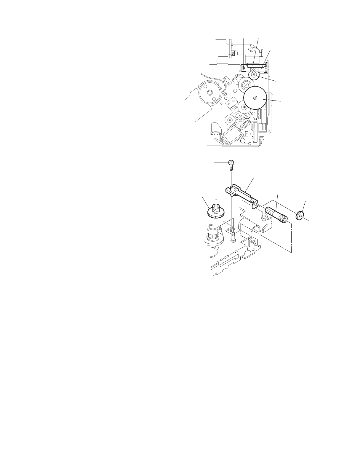
Page 24
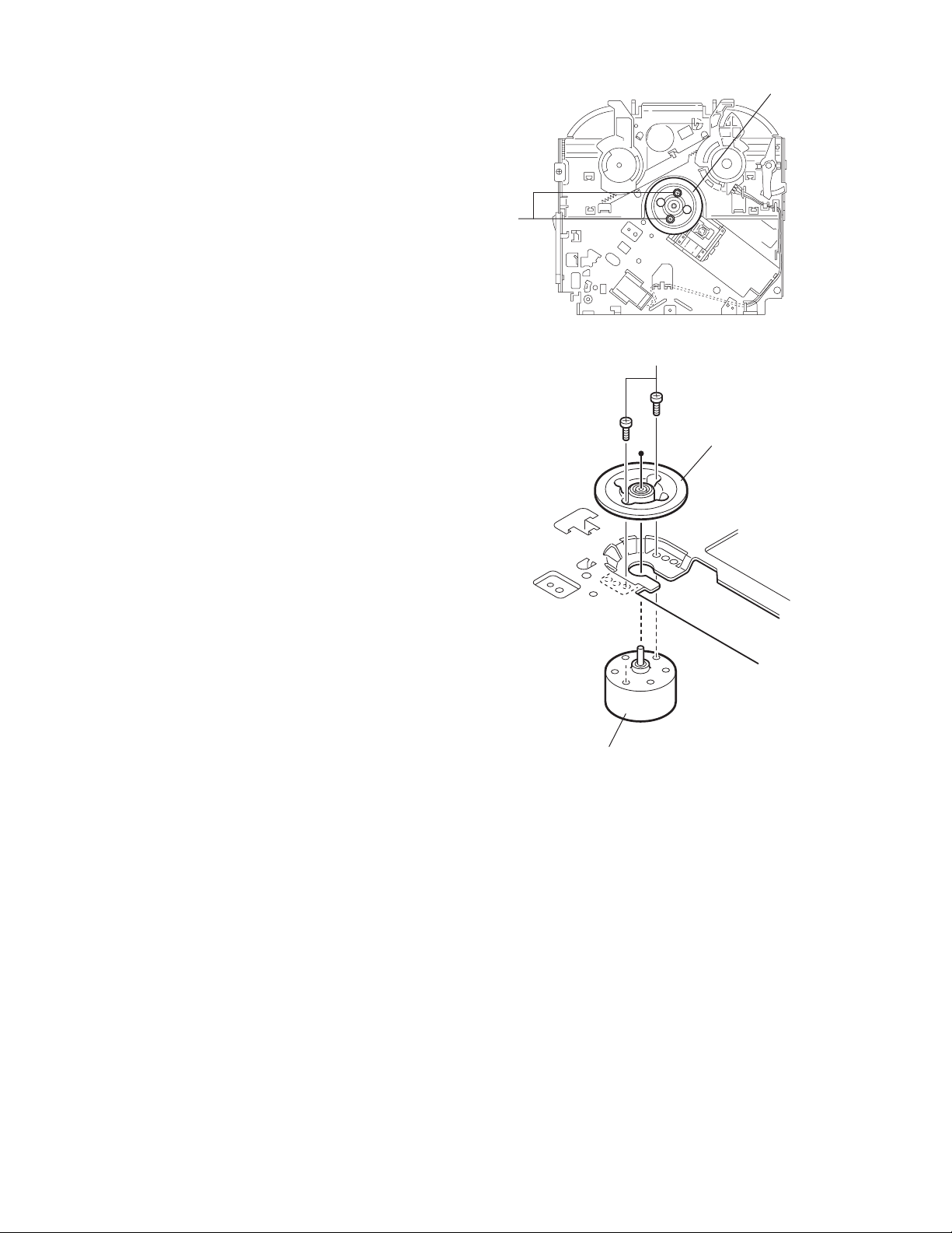
3.2.18 Removing the turn table / spindle motor
(See Figs.41 and 42)
• Prior to performing the follow ing procedure, remove the top
cover, connector board, chassis unit and clamper assembly.
(1) Remove the two screws L attaching the spindle motor as-
sembly through the slot of the turn table on top of the body.
(2) Unsolder the wire on the connector board if necessary.
Turn table
L
Fig.41
L
Turn table
1-24 (No.MA039)
Spindle motor
Fig.42
Page 25
SECTION 4
ADJUSTMENT
4.1 Adjustment method
Test instruments required for adjustment
(1) Digital oscilloscope (100MHz)
(2) AM Standard signal generator
(3) FM Standard signal generator
(4) Stereo modulator
(5) Electric voltmeter
(6) Digital tester
(7) Tracking offset meter
(8) Test Disc JVC :CTS-1000
(9) Extension cable for check
EXTSH002-22P × 1
Standard volume position
Balance and Bass &Treble volume : lndication"0"
Loudness : OFF
How to connect the extension cable for adjusting
Caution:
Be sure to attach the heat sink and rear bracket onto the power amplifier IC and regulator IC respectively, before supply the power.
If voltage is applied without attaching these parts, the power amplifier IC and regulator IC will be destroyed by heat.
Standard measuring conditions
Power supply voltage DC14.4V(10.5 to 16V)
Load impedance 20KΩ(2 Speakers connection)
Output Level Line out 2.0V (Vol. MAX)
Dummy load
Exclusive dummy load should be used for AM,and FM. For FM
dummy load,there is a loss of 6dB between SSG output and
antenna input.The loss of 6dB need not be considered since
direct reading of figures are applied in this working standard.
Heat sink
Extension cable
EXTSH002-22P
Rear bracket
(No.MA039)1-25
Page 26
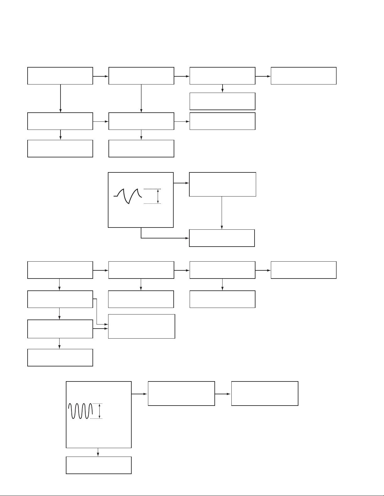
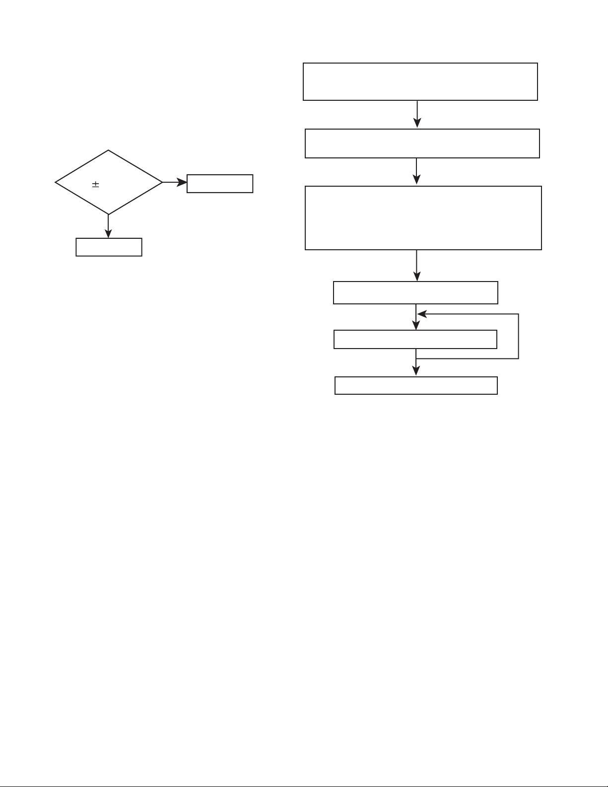
5.1 Feed section
SECTION 5
TROUBLE SHOOTING
Is the voltage output at
IC521 pin 40 5v or 0V
YES
Is 4V present at both
sides of the feed motor?
YES
Check the feed motor.
5.2 Focus section
5.3 Spindle section
NO
Is the wiring for IC521
pin 40 correct?
NO
Is 6V or 2V present at
IC561 pins 4 and 5?
Check IC561.
When the lens is
moving:
Does the S-search
waveform appear at
IC561 pins 8 and 9?
NO
NO
YES
4V
YES
YES
NO
Is 5V present at IC561
pins 3,12 and 21?
Check the vicinity of
IC521.
Check the feed motor
connection wiring.
Check the circuits in
the vicinity of IC561
pins 8 and 9.
Check the pickup and
its connections.
NO
Check CD 8V.
YES
YES
Is the disk rotated?
YES
Does the RF signal
appear at IC501 pin 19?
YES
Is the RF waveform
at IC501 pin 19
distorted?
YES
Proceed to the Tracking
section
5.4 Tracking section
When the disc is rotated
at first:
Is the tracking error
signal output at
IC501 pin 11?
NO
Is 4V present between
IC561 pins 6 and 7?
Check the spindle motor
and its wiring.
NO
Check the circuits in
the vicinity of IC501
pin 19 or the pickup.
NO
NO
Approx. 1.2V
NO
YES
Check the circuits in
the vicinity of IC561
pins 2 to 11.
Is 4V present at IC521
pin 41?
YES
Check the vicinity of
IC561
NO
Check the pickup and
its connections.
NO
Check IC521.
1-26 (No.MA039)
YES
Check IC521.
Page 27
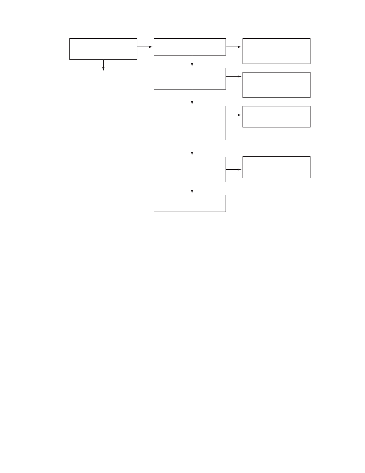
5.5 Signal processing section
Is the sound output from
both channels (L, R)?
Normal
YES
No sound from either
channel.
YES
Is 9V present at IC161 pin
31?
YES
NONO
Compare the L-ch and
R-ch to locate the
defctive point.
NO
Check the viciniyt of the
IC901 audio power
supply.
Is the audio signal
(including sampling output
components) output to
IC571 pins 1 and 7 during
playback?
YES
Is the audio signal output
at IC161 pins 3 and 30
during playback?
YES
Check the muting circuit.
NO
NO
Check IC571 and its
peripheral circuits.
Check IC161 and its
peripheral circuits.
(No.MA039)1-27
Page 28
5.6 Maintenance of laser pickup
(1) Cleaning the pick up lens
Before you replace the pick up, please try to clean the lens
with a alcohol soaked cotton swab.
(2) Life of the laser diode
When the life of the laser diode has expired, the following
symptoms will appear.
• The level of RF output (EFM output: amplitude of eye
pattern) will be low.
5.7 Replacement of laser pickup
Turn off the power switch and,disconnect the
power cord from the ac outlet.
Replace the pickup with a normal one.(Refer
to "Pickup Removal" on the previous page)
Is RF output
1.0 0.35Vp-p?
YES
O.K
(3) Semi-fixed resistor on the APC PC board
The semi-fixed resistor on the APC printed circuit board
which is attached to the pickup is used to adjust the laser
power.Since this adjustment should be performed to match
the characteristics of the whole optical block, do not touch
the semi-fixed resistor.
If the laser power is lower than the specified value, the laser diode is almost worn out, and the laser pickup should
be replaced. If the semi-fixed resistor is adjusted while the
pickup is functioning normally, the laser pickup may be
damaged due to excessive current.
NO
Replace it.
Plug the power cord in,and turn the power on.
At this time,check that the laser emits for
about 3seconds and the objective lens moves
up and down.
Note: Do not observe the laser beam directly.
Play a disc.
Check the eye-pattern at TP1.
Finish.
1-28 (No.MA039)
Page 29
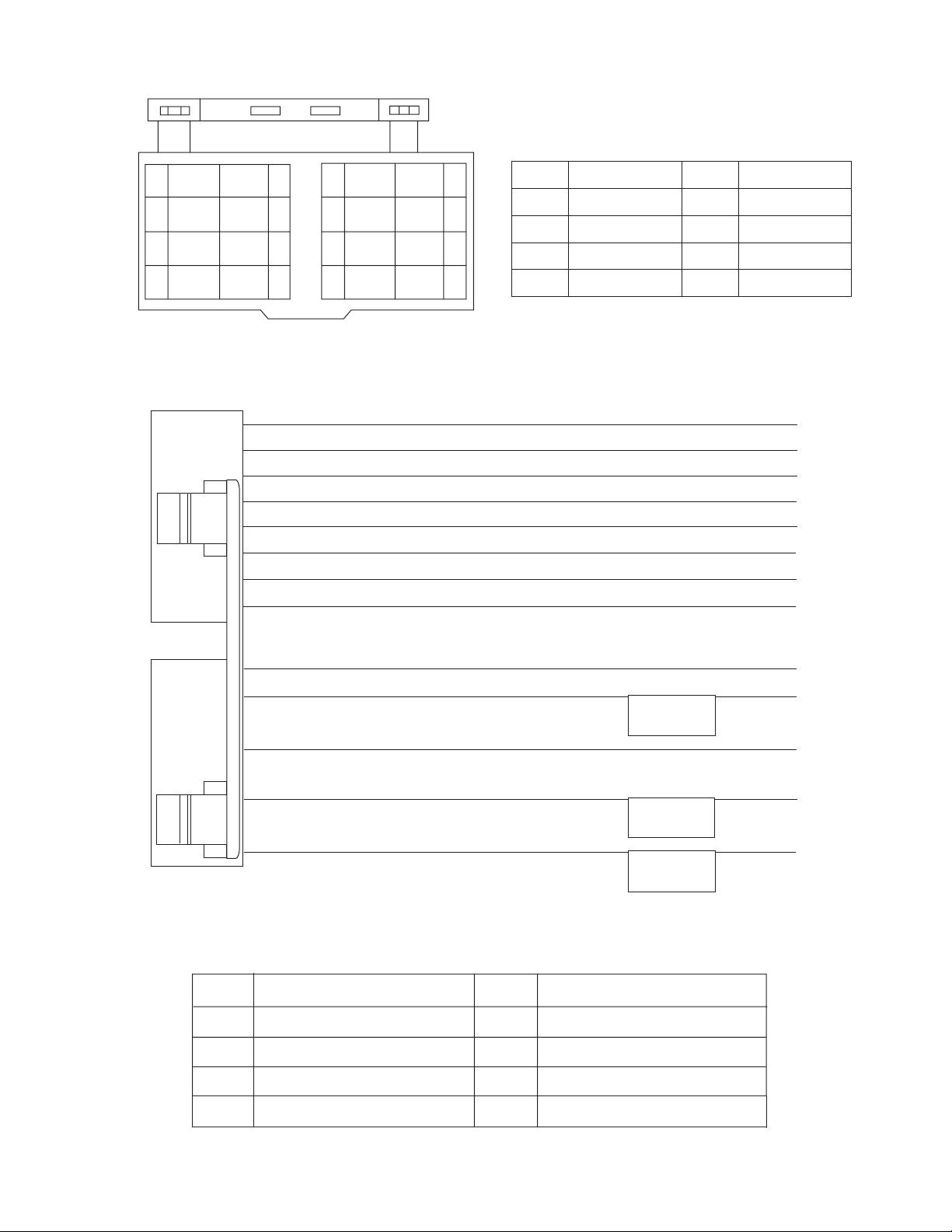
5.8 16 PIN CODE DIAGRAM
10
12
14
16
BR
YL
NC
BK
NC
NC
11
RD
13
15
1
2
3
4
5
6
7
8
BL/WH
9
VI
VI/BK
GY
GY/BK
WH
WH/BK
GN
GN/BK
VI/BK
2
4
GY/BK
WH/BK
6
8
GN/BK
RR+
RR-
FR+
FR-
FL+
FL-
RL+
RL-
VI
GY
WH
GN
1
BK
RD
Black
Red
3
BL
5
7
WH White
BR
Blue
Brown
GN
VI
GY
YL
Green
Violet
Gray
Yellow
RR
FR
FL
RL
10
BR
YL
12
BL/WH
13
RD
15
16
BK
Rear Right
Front Right
Front Left
Rear Left
TEL
MEMORY
REMOTE
ACC
GND
ANT
ACC
TEL
GND
MEMORY BACKUP
DIRECT TO BATTERY
ACC + 12Volt
Auto Antenna
ACC Line
Telephone Muting
Ground
+12Volt
GROUND
REMOTE
Remote
MEMORY
Memory Backup Battery+
(No.MA039)1-29
Page 30

VICTOR COMPANY OF JAPAN, LIMITED
AV & MULTIMEDIA COMPANY MOBILE ENTERTAINMENT CATEGORY 10-1,1chome,Ohwatari-machi,Maebashi-city,371-8543,Japan
(No.MA039)
Printed in Japan
WPC
Page 31

SCHEMATIC DIAGRAMS
CD RECEIVER
KD-G201,KD-G202,KD-G207
CD-ROM No.SML200401
KD-G201
KD-G202
KD-G201,KD-G202
Area suffix
STEERING CABLE
Contents
Block diagram
Standard schematic diagrams
Printed circuit boards
RDS
LINE OUT
KD-G207
KD-G201 E KD-G202 E/EX
E ----------- Continental Europe
EX --------------- Central Europe
KD-G207
Area suffix
EE --------- Russian Federation
KD-G207 EE/EX
2-1
2-2 to 7
2-8, 9
COPYRIGHT 2004 VICTOR COMPANY OF JAPAN, LTD.
No.MA039SCH
2004/1
Page 32

Safety precaution
!
!
Burrs formed during molding may be left over on some parts of the chassis. Therefore,
pay attention to such burrs in the case of preforming repair of this system.
Please use enough caution not to see the beam directly or touch it in case of an
adjustment or operation check.
Page 33

Block diagram
POSITION SET
SWITCH
LOAD&FEED
MOTOR
SPINDLE
MOTOR
SW1, SW2
PICK UP
PSW
FEED+
FEED-
SPINDLE+
SPINDLE-
SW1, SW2
VF1,VF2
VT1,VT2
LD,MD
TRACKING+
TRACKINGFOCUS+
FOCUS-
CN501
SW1,SW2,PSW
SPINDLE+
SPINDLEFEED+
FEEDTRACKING+
TRACKINGFOCUS+
FOCUS-
VF1,VF2
VT1,VT2
MD,LD
LM
IC561
CD
DRIVER
DMO,FMO
TRO,FOO
RFGC,RF
RFRP,RFDC
TEB,SEL
TE,FE
IC501
RF AMP
IC521
DSP&DAC
BUS0 to BUS3
BUCK,CCE
RST
CDRW
LO,RO
J1
ANT
FM/AM OSC
FM VT
AM VT
IFC
TU1
FM/AM
TUNER
IC701
CPU
SD/ST
MONO
SM,FM/AM
SEEK/STOP
L-CH
R-CH
IC161
E.VOLUME
SDA
SCL
RDSCL
RDSDA
IC71
RDS
DETECTOR
ONLY USED FOR
KD-G201,KD-G202
IC571
CD L.P.F.
CD.L
CD.R
OUTLF
OUTLR
OUTRF
OUTRR
REGULATOR
EACH BLOCK
IC901
REAR L
REAR R
IC301
POWER
AMP.
CN901
BATTERY
J321
LINE OUT
ONLY USED FOR
KD-G201,KD-G202
FRONT LEFT (+)
FRONT LEFT (-)
FRONT RIGHT (+)
FRONT RIGHT (-)
REAR LEFT (+)
REAR LEFT (-)
REAR RIGHT (+)
REAR RIGHT (-)
SPK
LCD1
COM1
COM2
COM3
S1 to S52
IC661
LCD
DRIVER
LCDCL
LCDDA
LCDCE
S601 to S618
KEY MATRIX
KEY0
KEY1
KEY2
JS601
ENCODER
ENC1
ENC2
CJ601
CN701
KEY0
KEY1
KEY2
LCDCL
LCDDA
LCDCE
ENC1
ENC2
STEERING
ONLY USED FOR
KD-G201,KD-G202
CN702
STEERING CABLE
ASSY
2-1
Page 34

Standard schematic diagrams
Main amplifier section (KD-G201, KD-G202)
TU1
1k
FMEO
UN2211-X
2.2/50
R43
MA8062/M/-X
C31
C32
1000P
Q31
D702
C1
5P
Q8
0.12
0.012
Q41
2SC3661-X
MA8062/M/-X
D703
C41
C42
MA8062/M/-X
D704
QAU0313-001
L1
4.7u
R31
1k
R41
3.3K
MA8062/M/-X
D705
D1
MA111-X
C12
0.47/50
MA8062/M/-X
D706
0.1
2SD601A/QR/-X
R45
Q42
C51
MA8062/M/-X
D707
D2
MA111-X
R35
Q32
2SC3661-X
SQ
MA8062/M/-X
R42
D708
C2
0.047
R32
10k
1k
1k
R51
470
MA8062/M/-X
D709
R1
100
2SB624/4/-X
Q6
FM/AM
100/10
Q51
R55
2.2k
Q5
R7
2SD601A/QR/-X
VDD
1000P
C81
C7
10p
R8
47k
4.7k
10
C9
R10
220/10
OSC
IFC
R56
47k
C54
0.01
C55
330p
47k
R57
SK/STP
R744
10K
C713
0.01
VSS
22K
R750
C3
1k
R44
C43
100/16
D701
0.47/50
33
0.33
C714
C11
2SB709A/R/-X
MA111-X
R52
15k
Q52
2SD601A/QR/-X
R53
10k
C711
0.1
MA8062/M/-X
150P
D4
R9
DETACH
ILL10V
ACC5V
REMOCON
DIMOUT
LCDCL
LCDDA
LCDCE
0.1
C712
C701
100P
C5
C4
C6
R2
10k
Q4
R6
47k
D3
MA111-X
UN2211-X
3.3k
R54
10k
C53
0.1
C52
4700p
ENC1
ENC2
RDSSCK
KEY0
KEY1
MONO
KEY2
SK/ST1
FM/AM
AFCK
RDSDA
DIMIN
DIMOUT
100p
220/10
(SHEET 2)
QAM0464-002
VMC0334-001
To CJ601
(SHEET 3)
J1
QNB0100-002
2SD601A/QR/-X
R33
1.5k
AMEO
SW5V
9V
CD.R
CD.L
PSW
SW1
SW2
LM
MSW
CDON
CD-RW
BUS0
BUS1
BUS2
BUS3
BUCK
CCE
RST
CD8V
CN701
CN702
QGA2006F1-02
1000P
C8
UNLOCK
1000P
C91
SK/ST1
J301
R332
R322
100
2.2k
R321
820
47k47k
R165R175
C801
0.01
C782
10/16
47/16
C903
R352 R342
100
Q321
Q351
2SD1781K/QR/-X
2SD1781K/QR/-X
820
R351
47k
R166
47k
R176
Q783
UN2111-X
D783
UDZS11B-X
22/16
IC901
AN80T07
R903
4.7k
10/16
C913
C352
0.47
9.1k
R902
C902
2.2/50
100
C186
R244
12k
100
SW1
R719
R720
R721
C243
22/16
0
R755
CD.L
CH.L
R245
180k
C244
1/50
22k
R246
R730
R732
47k
IC701
UPD178078GF-664
R729
4.7k
4.7k
4.7k
1/50
C185
1/50
C184
1/50
C183
1/50
C182
1/50
C181
1/50
220k
220k
R161
R171
D171
D161
MA111-X
MA111-X
CD.R
CH.R
47k
R247
POWER
R731
47k47k
100k
R733
47k
VPP
RESET
R728
47k
R727
10K
R726
47k
R725
47k
R752
10K
C708
X701
R724
0
QAX0793-001Z
0.1
C705
R723
47k
R722
47k
MA8062/M/-X
D710
R753
47K
R91
2SD601A/QR/-X
Q2
MA111-X
D71
AFCK
BUS2
BUS1
QAX0792-001Z
CCE
BUS0
SDA
R3
0
Q7
UN2211-X
BUCK
SCL
10k
2SD601A/QR/-X
10k
R81
Q74
C78
0.1
Q71
UN2111-X
R77
C74
47/6.3
0.01
C73
C72
47P
X71
R71
C71
82P
0.01
C716
LM
MSW
CD-RW
0
0
MSW
R739
R738
R705
R706
2.2k
2.2k
I/O
LCDDA
LCDCL
Q73
1500P
18K
R76
R82
0
R74
100
2.2k
2.2k
R72
RDSSCK
LM
2.2k
R754
R708
4.7k
R707
SW2
LCDCE
PSW
C83
Q72
UN2111-X
SAA6579T-X
LEVEL
R240
220
0.22
C241
CDON
0
IC71
RB160M-30-X
18K
C93
1500P
R75
R92
4.7k4.7k
2SD601A/QR/-X
C75
C79
560P
0.01
C76
0.022
C77
2.2/50
2.2k
R73
RDSDA
D241
C242
0.047
Q241
47k
MA111-X
2SD601A/QR/-X
R241
47k
R737
10k
10k
R712
R711
KEY0
ENC2
ENC1
R243
D242
R242
1k
CTRL
MUTE
REMOCON
TEL-MUTE
1k
4.7k
1.2k
R735
R736
R734
10k
10k
10k
10k
10k
10k
R713
R714
R715
R716
R717
R718
KEY2
KEY1
SM
SQ
LEVEL
C94
1/50
1/50
C84
C10
1/50
C82
0.012
C92
Q1
0.012
R4
4.7k
UN2211-X
Q3
UN2111-X
R11
10k
R5
47k
SK/STP
SD/ST
MONO
R58
47k
Q53
27k
R59
SM
C715
R742
47k
R743
47k
R751
R709
R710
UN2211-X
PS2
RST
BUS3
DETACH
R740
100K
10K
R741
0.01
4.7k
4.7k
4.7k
2.2k
R702
R703
R704
47k
47K
INT
SISOSCK
C13
220P
R163
2.2k
R162
22k
C162
8200P
C172
C191
47/16
C192
100/10
X1
15p
15p
C707
C706
0.1
C704
100/10
C703
0.01
C702
0.01
C166
C163
5600P
0.22
C165
0.033
0.22
C164
0.22
C174
C175
0.033
8200P
R172
C176
5600P
C173
0.22
22k
10
R173
2.2k
R191
SCLSISDA
TEL-MUTE
DIMIN
DIMOUT
FMEO
AMEO
OSC
IFC
SD/ST
CTRL
CD8V
ILL10V
PS2
Q902
UN2211-X
270
R174
R184
4.7K
R891
47k
D891
MA111-X
Q891
UN2211-X
C709
C710
L701
4.7u
Q901
2SB709A/QR/-X
IC161
TEA6320T-X
270
R164
R906
20k
C167
4.7/50
C177
4.7/50
100/16
C194
0.01
C193
R194
4.7K
MA111-X
R892
1k
D892
MA111-X
C891
0.1
100/10
0.01
L702
4.7u
MA111-X
R905
8.2k
C909
C908
220/10
220/10
Q331
R333 R323
2.2k
2SD1781K/QR/-X
820
R331
C168
4.7/50
C178
4.7/50
MUTE
Q781
UN2111-X
C781
D781
220/10
47K
Q881
R882
UN2211-X
R881
4.7K
C881
22/16
D902
220/10
0.01
C907
C916
C912
C904
10/16
QNN0519-001
100
C333
0.047
Q341
R341
R343R353
2SD1781K/QR/-X
820
2.2k2.2k
D341
D321
MA111-X
MA111-X
R167
C332
27k
0.47
R168
27k
C331
C351
390P
390P
C321
C341
390P
390P
R177
C342
27k
0.47
R178
C322
27k
0.47
D782
MA111-X
C783
0.22
C802
0.047
C910
UN2211-X
47/16
10k
R782
C784
1/50
Q782
SO
R802
100k
R801
100k
R810
100
R803
100k
1k
5.6k
R907
R904
0.1
0.1
C915
C911
C914
100/16
47k
R781
C905
C906
0.01
47/16
C324
0.047
IC801
HD74HC126FP-X
10k
R908
Q904
UN2111-X
C917
IC301
LA47515
C309
100P
C312
100P
C316
RB160M-30-X
QAM0175-002
0.1
RL-
RL+
FL-
FL+
C308
0.1
100P
100P
C315
C314
100P
100P
C318
C319
100P
100P
FR+
FR-
C311
0.1
C310
0.1
RR+
RR-
CH.L
CH.R
C323
1/50
C301
10/16
C302
C303
0.022
47/16
C320
1/50
C304
C305
C306
0.022
22/16
100/16
4.7k
R301
D302
D301
D303
D304
RB160M-30-X
SCK
C901
QEZ0625-338
C971
FR+
RB160M-30-X
0.1
D972
R971
R972
MA111-X
FL-
FL+
D903
RL-
D306
RB160M-30-X
2.2k
2.2k
RL+
RB160M-30-X
QNZ0095-001
RB160M-30-X
RB160M-30-X
POWER
I/O
INT
R808
100k
R804
10k
R809
330
R806
22k
R805
100
R807
100k
D901
IN5401-TU-15
L901
C918
CN901
QNZ0650-001
QMFZ047-150-T
100P
D971
RB160M-30-X
RR-
RR+
FR-
QQR0703-001
R901
1k
Q903
UN2211-X
0.1
D305
RB160M-30-X
J801
0.047
C325
D308
RB160M-30-X
C313
C317
D307
Parts are safety assurance parts.
When replacing those parts make
sure to use the specified one.
2-2
SHEET 1
Page 35

CD servo section (KD-G201, KD-G202)
FEED-
FEED+
GND
PSW
SPINDLE-
SPINDLE+
GND
SW1
SW2
TRACKING-
TRACKING+
FOCUS+
FOCUS-
LD
GND
MD
VR
VF1
VREF
VT1
GND
VT2
VCC
VF2
GND
FEED-
VF2
FEED+
VCC
GND
VT2
SW1
VT1
SW2
VF1
PSW
VR
SPINDLE-
LD
SPINDLE+
FOCUS-
VREF
FOCUS+
MD
TRACKING+
TRACKING-
FEED-
FEED+
SPINDLE-
SPINDLE+
FOCUS-
VREF
FOCUS+
TRACKING+
TRACKING-
CN501
QGB2027M4-22S
MSW
R566
VF2
VCC
VT2
SW1
VT1
SW2
VF1
PSW
R519
VR
150
LD
MD
VREF
C513
0.01
VF1
VF2
VT2
VT1
VCC
C501
0.01
R514
15k
R503
R504
R505
R506
C502
0.01
8.2k
R567
6.8k
IC561
LA6242H-X
3k
R568
R569
LM
R572
1.5k
1.5k
R571
C512
R513
1k
82p
R512 R511
2k 10k
C514
5p
IC501
TA2157FN-X
82k
82k
330k
330k
C503
100/6.3
R565
20k
5.1k
R576
C566
C565
C564
0.047
4.7K
R573
R515
100
C511
0.0470.047
C567
0.047
FOCUS-
FOCUS+
SPINDLE+
SPINDLE-
FEED-
FEED+
1.5k
RFGC
0.1
LD
Q501
0.01
C504
RF
C510
MD
2SB1241/QR/-T
TRACKING-
TRACKING+
C509
100/6.3
TP1
RFRP
56k
0.1
R510
SEL
TEB
100/6.3
C505
22
R507
R508
22
4.7k
R563
R564
R562
R577
8.2k
C568
0.022
C508
0.01
FE
R509
82k
RFDC
FMO
15k
DMO
8.2k
FOO
C561
47/6.3
Q561
2SB1322/RS/-T
22
22
R574
R575
R561
33k
TRO
C562
C563
0.01
100/10
TP2
R517
0
CD-RW
C507
0.0068
R516
820
TE
1A3G-T1
D561
Q521
UN2111-X
Q522
UN2211-X
C559
1800P
L521
47u
47u
L523
C557
100P
4.7k
4.7k
4.7k
L522
R537
R536
R535
47u
0.1
C547
100/6.3
C555
100/6.3
C548
0.01
C549
BUCK
BUS0
CCE
BUS1
BUS2
RST
4.7k
BUS3
R534
CDON
R538
C552
0.01
C551
100/10
R594
150
C594
820p
C584
820p
R584
150
C553
C545
100/6.3
C546
100p
C544
0.01
10p
C554
10p
R533
1M
X521
QAX0794-001Z
10k
C556
0.1
1/50
C550
C592
R591
18k
4.7/25
820p
C591
C581
820p
C582
R581
18k
4.7/25
FMO
DMO
0.01
C539
100/6.3
C541
100
100
R531
R532
47u
L524
C521
22k22k
R586R587
C585
22k 22k
R597 R596
C595
47/6.3
FOO
TRO
C538
C537
C534
C540
0.01
C533
R530
R529
R526
100
R528
R527
100
0.01
C522
100/6.3
R592
33k
C593
R593
12k
120p
C583
R583
12k
120p
R582
33k
47/6.3
C596
0.047
0.047
470p
470p
0
0
0
C530
R521
5.6k
IC521
TC94A14FA
C527
C526
C525
0.047
0.047
0.047
C531
C535
C536
0.033
C528
R525
0.033
10k
0.01
2700P
0.01
R524
C524
0.015
15k
R523
470k
R539
1.5M
R522
47k
0
R595
IC571
NJM4565M-WE
R585
100/16
C597
0.001
RFGC
RFDC
FE
C529
100/6.3
47p
C523
CD.L
0
CD.R
SEL
TEB
SW5V
9V
CD.R
TE
RFRP
RF
C560
0.047
AGND
CD.L
PSW
SW1
SW2
LM
MSW
CDON
CD-RW
BUS0
BUS1
BUS2
BUS3
BUCK
CCE
RST
CD8V
GND
(SHEET 1)
(SHEET 1)
SHEET 2
2-3
Page 36

LCD & Key control section (KD-G201, KD-G202)
S601
R614R615
S617S618
R605
2.7k
S602
1.8k
S611
R613
S616
R609
R608
1.2k
S610
R612 R611
1.2k 820
LCD1
R601
R602R603R604
8201.2k1.8k
R607
820
KEY2
820
S605S604S603
S606
R606
KEY1
820
S607
S608S609
R610
KEY0
8201.8k2.7k3.9k
S612S613S614S615
SML-310LT/MN/-X
R630
D630
S1
COM2
COM1
COM3
R631
D635
D631
R632
R633
820
D632
D633
D634
R634
IC681
RPM7338-V4
JS686
QSW0863-003
C682
D681
0.012
MA8062/M/-X
C681
10K
R682
S50
S49
S48
S47
S46
S45
S44
S43
S42
S41
S40
S39
S38
S37
S36
S35
S34
S33
S32
S31
S30
S29
S28
S27
S26
S25
S24
S23
S22
S21
S20
S19
S18
S17
S16
S15
S14
S13
S12
S11
S10S9S8S7S6S5S4S3S2
D644
D645
R644
R645
D647
D646
R646
D649
D648
R651
R637
D636
D637
R638
R639
D640
D638
D639
R640
R641
D643
D642
D641
R642
R643
R652
R627
S51
S52
R661
2.2K
R662
180K
R663
10/6.3
C661
R664
2.2K
10K
D661
MA111-X
D650
0
R626
0
D651
R647
R648
R653
R654
R649
D652
390
R650
D653
390
R670
470
Q670
2SB624/4/-X
R672
Q671
UN2211-X
R671
47K
1K
C662
680p
IC661
PT6523LQ
D662
UDZS5.1B-X
R665
51K
LCD.CE
LCD.SCK
LCD.SO
0.022
C663
R666
R667
R668
10K
10K
10K
S49
S50
S51
S52
COM1
COM2
COM3
INH
OSC
CE
CLK
DATA
4.7/6.3
S47
S48
S2
S1
R681
470
S44
S45
S46
S3S4S5S6S7
R687
47K
R688
47K
S37
S40
S41
S42
S43
S38
S39
S9
S8
S11
S10
S12
100
R686
C687
C686
S36
S13
0.022
0.022
S33
S34
S35
S32
S31
S30
S29
S28
S27
S26
S25
S24
S23
S22
S21
S20
S19
S18
S17
S14
S16
S15
CJ601
VMC0335-001
ILL10V
REMOCON
DIMOUT
LCDCL
LCDDA
LCDCE
ACC5V
ENC1
ENC2
KEY0
KEY1
KEY2
To CN701
(SHEET 1)
2-4
DIMMER
SHEET 3
Page 37

Main amplifier section (KD-G207)
e
TU1
2.2/50
2SD601A/QR/-X
R43
1k
FMEO
C1
5P
UN2211-X
C31
C32
1000P
Q31
MA8062/M/-X
D702
C42
0.082
Q41
2SC3661-X
MA8062/M/-X
D703
Q8
0.22
C41
QAU0314-001
L1
4.7u
R31
1k
MA8062/M/-X
D704
D1
MA111-X
C12
R41
1k
0.47/50
MA8062/M/-X
D705
0.1
Q42
C51
MA8062/M/-X
D706
D2
MA111-X
R35
Q32
2SD601A/QR/-X
R42
1k
R45
2SC3661-X
SQ
R51
470
MA8062/M/-X
MA8062/M/-X
D708
D707
C2
0.047
R32
10k
1k
C43
100/16
MA8062/M/-X
D709
1k
C3
D701
0.47/50
R44
33
Q52
2SD601A/QR/-X
0.33
C714
MA8062/M/-X
R52
15k
C711
(SHEET 5)
VMC0334-001
To CJ601
(SHEET 6)
QAM0464-002
J1
QNB0100-002
R33
1.5k
AMEO
SW5V
9V
CD.R
CD.L
PSW
SW1
SW2
LM
MSW
CDON
CD-RW
BUS0
BUS1
BUS2
BUS3
BUCK
CCE
RST
CD8V
GND
CN701
CN702
QGA2006F1-02
C11
150P
2SB709A/R/-X
MA111-X
R53
10k
REMOCON
C712
0.1
0.1
DETACH
ILL10V
ACC5V
DIMOUT
100P
D4
R9
LCDCL
LCDDA
LCDCE
C701
J301
R332
100
C186
100
C243
22/16
SW1
R755
R719
R720
R721
1/50
C185
1/50
C184
1/50
C183
1/50
C182
1/50
C181
1/50
C191
220k
220k
R161
R171
47/16
D171
D161
MA111-X
MA111-X
CD.R
CD.L
CH.L
CH.R
180k
R245
C244
1/50
47k
22k
R247
R246
POWER
R731
47k47k
R730
100k
R732
R733
47k
0
IC701
UPD178078GF-665
R729
47k
VPP D971
RESET
R728
47k
R727
10K
R726
47k
R725
47k
R752
R724
0
R723
47k
R722
D710
R753
4.7k
4.7k
4.7k
10K
X701
QAX0793-001Z
C705
47k
MA8062/M/-X
47K
X1
SD/ST
15p
C708
15p
C707
0.1
C704
100/10
C703
0.01
R91
2SD601A/QR/-X
Q2
MA111-X
D71
AFCK
BUS2
BUS1
10k
2SD601A/QR/-X
R81
10k
Q74
R3
0
C78
0.1
Q71
UN2111-X
R77
C74
47/6.3
0.01
C73
C72
47P
X71
R71
QAX0792-001Z
C71
82P
Q7
UN2211-X
C716
0.01
LM
MSW
CCE
BUS0
BUCK
CD-RW
0
0
MSW
R738
R739
2.2k
R706
R705
2.2k
I/O
LCDDA
LCDCL
SDA
SCL
Q73
1500P
18K
R76
R82
0
R74
100
2.2k
SAA6579T-X
2.2k
R72
RDSSCK
LM
2.2k
R754
R708
4.7k
R707
SW2
LCDCE
PSW
LEVEL
0.22
C241
CDON
0
C83
Q72
UN2111-X
IC71
R240
220
R75
4.7k4.7k
RB160M-30-X
47k
R737
10k
10k
R711
R712
ENC2
ENC1
D241
47k
R241
10k
R713
KEY0
18K
R92
2SD601A/QR/-X
C75
560P
MA111-X
D242
MUTE
1.2k
R736
10k
10k
R714
R715
KEY1
KEY2
C93
1500P
C79
0.01
C76
0.022
C77
2.2/50
2.2k
R73
RDSDA
C242 R244
0.047
Q241
2SD601A/QR/-X
R242
1k
CTRL
TEL-MUTE
1k
R734
R735
10k
10k
R716
R717
SM
LEVEL
12k
R243
REMOCON
4.7k
10k
R718
SQ
C94
1/50
C84
UN2211-X
10k
2.2k
1/50
C10
1/50
C82
0.012
C92
0.012
Q1
R4
4.7k
Q3
UN2111-X
R5
47k
MONO
SD/ST
SK/STP
R58
47k
Q53
UN2211-X
PS2
RST
BUS3
DETACH
R740
100K
10K
R741
4.7k
4.7k
4.7k
R702
R703
R704
47k
47K
INT
SISOSCK
R1
100
1000P
C7
10p
Q5
R8
47k
R7
4.7k
R56
47k
2SD601A/QR/-X
R57
R744
10K
C713
0.01
VDD
1000P
C81
C91
10
R11
1000P
C9
C8
R10
220/10
IFC
OSC
SK/ST1
C54
0.01
C55
330p
27k
R59
47k
SM
SK/STP
C715
0.01
R742
47k
R743
47k
UNLOCK
VSS
R751
22K
R709
R750
R710
100p
220/10
C5
C4
C6
R2
100/10
10k
Q4
R6
47k
2SB624/4/-X
D3
MA111-X
Q6
UN2211-X
3.3k
FM/AM
R54
10k
Q51
C53
0.1
R55
2.2k
C52
4700p
ENC1
ENC2
RDSSCK
KEY0
KEY1
MONO
KEY2
SK/ST1
FM/AM
AFCK
RDSDA
DIMIN
DIMOUT
C13
220P
R163
2.2k
R162
22k
C163
0.22
C166
C162
C172
C192
100/10
C702
0.01
5600P
C165
8200P
0.033
0.22
C164
0.22
C174
0.033
C175
8200P
R172
C706
0.1
C176
5600P
C173
0.22
22k
R173
2.2k
10
R191
SCL
4.7K
TEL-MUTE
DIMIN
DIMOUT
FMEO
AMEO
OSC
IFC
CTRL
CD8V
ILL10V
PS2
Q902
UN2211-X
R184
270
R174
L701
4.7u
2SB709A/QR/-X
270
R164
SDA
R891
47k
D891
MA111-X
Q891
UN2211-X
C709
C710
Q901
TEA6320T-X
C167
4.7/50
IC161
C177
4.7/50
100/16
C194
0.01
C193
MUTE
Q781
UN2111-X
R194
4.7K
MA111-X
R892
1k
D892
MA111-X
C891
0.1
100/10
0.01
L702
4.7u
MA111-X
R905
8.2k
R906
20k
C909
C908
220/10
220/10
Q331
R333 R323
2.2k
2.2k
820
2SD1781K/QR/-X
R331
C168
4.7/50
C178
4.7/50
C781
D781
220/10
UN2111-X
47K
Q881
R882
UN2211-X
R881
4.7K
C881
22/16
D902
220/10
0.01
C916
C907
C912
C904
10/16
R352
R322
100
100
Q321
Q351
R353
2SD1781K/QR/-X
2SD1781K/QR/-X
R321
820
820
R351
C352
0.47
47k47k
47k
R165R175
R166
C342
47k
0.47
R176
C801
0.01
Q783
UDZS11B-X
D783
22/16
C782
IC901
AN80T07
4.7k
9.1k
R903
R902
10/16
10/16
47/16
C903
C913
C902
QNN0519-001
R342
100
C333
0.047
Q341
R343
R341
2SD1781K/QR/-X
2.2k2.2k
820
D341
D321
MA111-X
MA111-X
R167
C332
27k
0.47
R168
27k
C331 C351
390P 390P
C341 C321
390P
C322
0.47
C802
0.047
C910
UN2211-X
R801
47/16
390P
R178
27k
R782
10k
C784
Q782
C911
1/50
SO
R802
100k
100k
R810
100
R803
100k
1k
R907
R904
5.6k
0.1
0.1
C915
C914
100/16
R177
27k
47k
R781
D782
MA111-X
C783
0.22
SI
C905
C906
47/16
0.01
2.2/50
C324
0.047
IC801
HD74HC126FP-X
10k
R908
Q904
UN2111-X
C917
IC301
LA47515
C309
0.1
C323
1/50
C313
C325
D308
0.047
D307
RB160M-30-X
C317
RB160M-30-X
100P
100P
C301
10/16
C302
C303
0.022
47/16
C320
1/50
C305
C304
C306
0.022
22/16
100/16
R301
4.7k
D304
D306
D302
D301
D303
RB160M-30-X
D972
R971
R972
FL-
FL+
RB160M-30-X
0.1
RL-
RB160M-30-X
2.2k
2.2k
D903
MA111-X
RL+
D305
RB160M-30-X
QNZ0095-001
RB160M-30-X
J801
RB160M-30-X
RB160M-30-X
POWER
SCK
INT
I/O
R808
100k
R804
10k
R809
330
R806
22k
R805
100
R807
100k
D901
1N5401-TU-15
C901
3300/16
100P
C918
L901
QQR0703-001
R901
1k
QNZ0650-001
CN901
QMFZ047-150-T
Q903
UN2211-X
0.1
RB160M-30-X
RR-
C971
RR+
FR+
FR-
100P
C312
100P
C316
QAM0175-002
RL-
RL+
FL-
C308
0.1
FL+
100P
C314
C315
100P
100P
C318
C319
100P
FR+
FR-
C311
0.1
C310
0.1
RR+
RR-
CH.L
CH.R
Parts are safety assurance parts.
When replacing those parts mak
sure to use the specified one.
SHEET 4
2-5
Page 38

CD servo section (KD-G207)
FEED-
FEED+
GND
PSW
SPINDLE-
SPINDLE+
GND
SW1
SW2
TRACKING-
TRACKING+
FOCUS+
FOCUS-
LD
GND
MD
VR
VF1
VREF
VT1
GND
VT2
VCC
VF2
GND
FEED-
VF2
FEED+
VCC
GND
VT2
SW1
VT1
SW2
VF1
PSW
VR
SPINDLE-
LD
SPINDLE+
FOCUS-
VREF
FOCUS+
MD
TRACKING+
TRACKING-
SPINDLE-
SPINDLE+
FOCUS-
FOCUS+
TRACKING+
TRACKING-
CN501
QGB2027M4-22S
MSW
FEED-
VF2
FEED+
VCC
VT2
SW1
VT1
SW2
VF1
PSW
R519
VR
150
LD
VREF
MD
VREF
C513
0.01
VF1
VF2
VT2
VT1
VCC
C501
0.01
R514
15k
R503
R504
R505
R506
C502
0.01
R566
8.2k
R567
6.8k
IC561
LA6242H-X
3k
R568
LM
1.5k
R572
1.5k
R571
C512
R513
1k
82p
R512 R511
2k 10k
C514
5p
IC501
TA2157FN-X
82k
82k
330k
330k
C503
100/6.3
R565
5.1k
20k
R576
C566
C565
C564
0.047
4.7K
R569
R573
R515
100
0.0470.047
C567
0.047
FOCUS-
FOCUS+
FEED-
SPINDLE+
SPINDLE-
FEED+
1.5k
RFGC
0.1
C511
LD
Q501
C504
0.01
RF
C510
MD
2SB1241/QR/-T
TRACKING-
TRACKING+
C509
100/6.3
TP1
RFRP
56k
0.1
R510
SEL
TEB
100/6.3
C505
22
R507
R508
22
4.7k
R563
R564
R562
R577
8.2K
C568
0.1
C508
0.01
FE
R509
82k
RFDC
FMO
15k
DMO
8.2k
FOO
C561
47/6.3
Q561
2SB1322/RS/-T
22
22
R574
R575
R561
33k
TRO
C562
C563
0.01
100/10
TP2
R517
0
CD-RW
C507
0.0068
R516
820
TE
1A3G-T1
Q521
UN2111-X
D561
C559
1800P
L521
47u
47u
Q522
UN2211-X
L523
C557
100P
4.7k
4.7k
4.7k
4.7k
L522
R537
R536
R535
47u
R534
0.1
C547
100/6.3
C555
100/6.3
C548
0.01
C549
BUCK
BUS0
CCE
BUS1
BUS2
RST
BUS3
R538
C552
0.01
C551
CDON
100/10
R594
150
C594
820p
C584
820p
R584
150
C553
C545
100/6.3
C546
100p
C544
0.01
10p
C554
10p
R533
1M
X521
QAX0794-001Z
10k
C556
0.1
C550
1/50
C592
R591
18k
4.7/25
820p
C591
C581
820p
C582
R581
18k
4.7/25
FMO
DMO
0.01
C539
C541
100
100
R531
R532
47u
L524
C521
100/6.3
R586R587
22k22k
C585
R597 R596
22k 22k
C595
47/6.3
FOO
TRO
C538
C537
C534
C540
0.01
C533
R530
R529
R526
100
R528
R527
100
C522
0.01
100/6.3
R592
33k
C593
12k
R593
120p
C583
R583
12k
120p
R582
33k
47/6.3
C596
0.047
R521
5.6k
0.047
470p
470p
0
0
0
TC94A14FA
C530
0.047
0.047
0.047
C531
C535
C536
IC521
0.033
C528
R525
0.033
10k
0.01
C527
2700P
C526
0.01
C525
R524
C524
0.015
15k
R523
470k
R539
1.5M
R522
47k
0
R595
IC571
NJM4565M-WE
R585
100/16
C597
0.001
C529
100/6.3
47p
C523
CD.L
0
CD.R
SEL
TEB
RFGC
SW5V
9v
CD.R
SW2
LM
MSW
CDON
CD-RW
BUS0
BUS3
BUCK
AGND
CD.L
PSW
SW1
BUS1
BUS2
CCE
RST
CD8V
GND
(SHEET 4)
(SHEET 4)
TE
RFDC
FE
RFRP
RF
C560
0.047
2-6
SHEET 5
Page 39

LCD & Key control section (KD-G207)
LCD1
R601
R608
1.2k
S610
R612 R611
1.2k 820
R602R603R604
8201.2k1.8k
R607
820
KEY2
820
S606
S605S604S603
R606
KEY1
820
S607
S608S609
R610
KEY0
8201.8k2.7k3.9k
S612S613S614S615
R630
D630
SML-310LT/MN/-X
S601
R605
2.7k
S602
R609
1.8k
S611
R613
R614R615
S616
S617S618
IC681
RPM7338-V4
JS686
QSW0863-003
C682
D681
0.012
MA8062/M/-X
C681
10K
R682
S50
S49
S48
S47
S46
S45
S44
S43
S42
S41
S40
S39
S38
S37
S36
S35
S34
S33
S32
S31
S30
S29
S28
S27
S26
S25
S24
S23
S22
S21
S20
S19
S18
S17
S16
S15
S14
S13
S12
S11
R632
R633
D632
D633
D634
R634
S10S9S8S7S6S5S4S3S2
R637
D636
D637D635
R638
R639
D640
D638
D639
R640
R641
D643
D642
D641
R642
R643
D644
D645
R644
R645
D647
D646
R646
R651
D649
D648
R652
R627
S51
S52
R661
2.2K
R662
180K
R663
10/6.3
C661
R664
2.2K
10K
D661
MA111-X
D650
0
R626
0
D651
R647
R648
R653
R654
R649
D652
390
R650
D653
390
R670
470
Q670
2SB624/4/-X
R672
Q671
UN2211-X
R671
47K
1K
C662
680p
IC661
PT6523LQ
D662
UDZS5.1B-X
R665
51K
LCD.CE
LCD.SCK
LCD.SO
0.022
C663
R666
R667
R668
10K
10K
10K
S1
COM2
COM1
COM3
820
D631
R631
S49
S50
S51
S52
COM1
COM2
COM3
INH
OSC
CE
CLK
DATA
4.7/6.3
S47
S48
S2
S1
R681
470
S44
S45
S46
S3S4S5S6S7
R687
47K
R688
47K
S37
S40
S41
S42
S43
S38
S39
S9
S8
S11
S10
100
R686
C687
C686
S36
S12
S13
0.022
0.022
S33
S34
S35
S32
S31
S30
S29
S28
S27
S26
S25
S24
S23
S22
S21
S20
S19
S18
S17
S14
S16
S15
CJ601
VMC0335-001
ILL10V
ACC5V
REMOCON
ENC1
ENC2
DIMOUT
LCDCL
LCDDA
LCDCE
KEY0
KEY1
KEY2
To CN701
(SHEET 4)
DIMMER
SHEET 6
2-7
Page 40

Printed circuit boards
Main board
C325
IC301
R526
R529
R530
C503
C505
C304
Q501
C536
C529
R167
B7
C535
B1
B2
C531
R168
C320
IC501
D307
R178
C507
C522
B5
B6
C305
C303
R177
D308
B14
L524
C324
R503
R505
B3
R504
R506
R523
C530
C539
C319
C313
C312
C318
C514
C509
C316
B10
R519
C510
R510
C317
B4
CN501
R514
D304
IC521
D303
Q561
X521
D302
D306
C315
D301
D305
C314
C784
L522
C551
C901
C546
C544
C301
IC561
CN901
C323
C322
C550
C545
C563
C561
C548
C559
C555
R576
D901
C332
C567
D561
R594
L521
C591
R591
C594
R584
R597
C584
C902
C782
C581
R581
Main board
Forward side Reverse side
C352
C342
C781
C592
L523
L901
R901
C595
C593
R801
R802
C913
R804
C802
C916
B8
B9
IC571
R587
C582
CN702
R596
C167
D781
C585
IC801
C177
C904
Q781
R702
C881
C596
C583
R703
R704
IC901
R743
R709
R244
C905
R710
R245
C910
R742
R808
R809
Q241
C178
C701
R707
C914
C168
R750
R243
C244
C907
IC161
R751
C713
C193
C165
R246
R739
C243
R247
C903
B13
R738
Q903
R904
C175
C183
Q904
C164
R714
R908
R715
R907
C192
R736
IC701
R721
R713
J801
R735
R719
C184
C704
R720
C182
PP2
CN701
R905
C705
R717
L701
R906
X701
R718
C181
Q902
L702
Q901
C191
C186
C909
R4
Q3
R323
C709
D71
R723
Q321
D341
C185
C908
R722
C10
Q71
D3
R75
R752
D321
R9
R74
Q72
C51
D4
Q73
R352
R342
R351
R341
R322
R332
C2
C77
C84
J301
C801
R57
R11
R52
C71
C72
Q51
R10
C9
R31
C53
C4
R741
D709
R41
C41
C31
X71
C43
Q42
R32
D708
R44
R43
C42
C909
R51
C51
C711
D707
R729
R734
R56
D706
R331
R42
R81
R711
D705
C185
R82
C93
C704
C10
C13
C707
C83
R92
R58
R321
C908
R54
Q53
C710
R724
X701
R161
C186
RESET
C708
CN701
D1
D2
PP1
C3
Q41
C6
Q31
R1
R91
C94
R71
J301
Q341
Q331
R333
C43
R6
Q6
R7
R8
Q7
X71
C9
Q351
R353
R343
PP1
Q4
Q5
C6
C715
C32
R33
C94
R53
R55
Q52
C4
R72
R73
C31
R76
C78
C52
C3
C84
Q74
R744
C79
B12
C77
IC71
J1
L1
TU1
C75
C74
C333
J1
L1
TU1
C1
Q8
C12
R77
C73
C92
R59
C55
C81
C91
Q1
C7
C82
C11
C74
R45
C5
R2
Q32
R35
C8
C54
R5
C716
C76
C714
C712
R171
R3
J801
PP2
C181
R172
C172
C174
C173
C192
C191
D161
D171
R173
C182
C183
R730
R755
L701
L702
C709
R728
R726
X1
C702
C703
Q2
D710
R716
R712
D704
R191
C162
C706
D703
C184
R725
D702
R162
LM
R753
C241
C903
C163
R240
R163
VPP
R727
C166
R241
C243
R194
C193
MSW
VDD
R706
R754
C915
C194
C176
D902
UNLOCK
VSS
R705
C912
R708
R740
R242
C907
C244
R175
R184
Q891
R891
D241
R892
R164
R174
D242
C178
C168
R882
D891
IC901
C914
D892
R731
R165
R733
R806
C242
C910
R732
C177
C167
C881
R737
R586
C596
Q881
R582
R583
C911
C905
C904
R807
C906
R585
C891
Q782
R595
R803
R176
R782
R166
R805
C585
R810
C916
D782
R881
C557
C597
R901
R781
C781
C913
C902
C582
R902
R903
Q783
R566
C595
D783
C783
C560
D901
B8
B9
CN702
R567
C782
D561
D701
R563
C562
R592
C548
R301
R593
Q521
Q522
C547
L523
L521
C592
R572
R571
R573
R575
R535
C549
L901
C918
C352
R574
C901
C342
R569
R568
C563
C556
C322
C555
C550
C332
R537
R565
C545
C566
C561
C551
R527
R528
C534
C565
C310
C323
C301
C784
TP2
Q561
C552
C553
R534
R536
X521
R577
L522
R532
C564
R538
D971
D972
R971
C538
R533
C311
R531
C971
R972
C554
B3
B4
R561
R525
R517
C509
C308
C305
C537
C539
D903
CN501
R562
B1
B2
C501
C513
R564
C341
C512
R511
C528
C540
C541
CN901
C309
C321
R513
R512
C508
L524
R521
R515
C511
C303
C522
C320
C525
C502
R516
C526
C351
R509
C331
C521
C529
C304
C503
C505
C504
R507
R508
TP1
IC301
Q501
C527
C533
R524
C524
C306
R539
C302
R522
C523
2-8
Page 41

Front board
Forward side
R601
D638 D639
R602
S604 S605
LCD1
S603
R603
D640
R604
D641
R605
S601 S602
D642
D635
D637
S609
D631
R609
R607
S611
R608
S610
S606
D632
D633
D634
R630
D636
JS686
D630
Reverse side
R646
R645
R670
D662
C663
IC661
R671
D653
R644
CJ601
R643
C661
R650
C662
R665
R667
R668
R666
Q670
R662
R664
D652
R649
R672
Q671
D661
R661
R681
R682
R663
IC681
D681
R648
C681
C682
R647
R606
S612
S608
S607
R610
S613
D643
D644
D645
D646
D647
S614
R652
R651
R611
D648
S615
D653
R612
S616
R613
R654
R614
D652
D649
S618
R653
D651
D650
S617
IC681
R615
R626
R642
R640
R641
R632
R639
R634
R633
C687
R631
R687
R688
R686
C686
R637
R638
JS686
D629
2-9
Page 42

VICTOR COMPANY OF JAPAN, LIMITED
AV & MULTIMEDIA COMPANY MOBILE ENTERTAINMENT CATEGORY 10-1,1chome,Ohwatari-machi,Maebashi-city,371-8543,Japan
(No.MA039SCH)
Printed in Japan
WPC
Page 43

PARTS LIST
[ KD-G201]
[ KD-G202]
[ KD-G207]
* All printed circuit boards and its assemblies are not available as service parts.
KD-G201, KD-G202
Area suffix
E ----------- Continental Europe
EX --------------- Central Europe
KD-G207
Area suffix
EE---------- Russian Federation
- Contents -
Exploded view of general assembly and parts list (Block No.M1)
CD mechanism assembly and parts list (Block No.MB)
Electrical parts list (Block No.01~02)
Packing materials and accessories parts list (Block No.M3)
3- 2
3- 4
3- 6
3-14
MA039
3-1
Page 44

Exploded view of general assmbly and parts list
Main board
9
53
51
Block No.
M
M
1
M
52
48
9
9
50
49
54
A
1
2
B
3
7
10
C
7
C
56
A
8
14
15
Main board
8
B
18
39
13
6
12
6
23
6
26
17
27
13
16
28
21
39
11
Front
board
29
31
5
38
32
57
33
30
35
34
4
19
37
36
42
47
41
43
44
45
LCD1
46
40
3-2
20
22
25
24
Page 45

General assembly
Block No. [M][1][M][M]
Symbol No.
1 GE10043-210 A TOP CHASSIS
2 GE40135-001A EARTH PLATE
3 GE30938-0 03A SIDE PANEL
4 GE30393-0 02 A BOTTOM COVER
5 FSMA3004-203 INSULATOR
6 QYSDST2604Z SCREW 2.6mm x 4mm(x3)
7 FSKZ4005-001 SCREW (x2)
8 QYSDST2606Z SCREW 2.6mm x 6mm(x2)
9 QYSDST2604Z SCREW 2.6mm x 4mm(x3)
10 QYSDST2610Z SCREW 2.6mm x 10mm
11 GE10079-001A F RO N T CHASSIS
12 FSYH4036-098 SHEET
13 QYSDST2004M MINI SCREW 2mm x 4mm(x2)
14 GE31033-001A LOCK LEVER
15 FSKW40 05-003 TORSION SPRING
16 FSWK3002-015
17 GE31034-001A R LS KNOB
18 GE40156- 001A BLIND
19 GE10077- 001A FRONT PANEL
20 GE31031-019A F IN D ER ASSY
20 GE31031-020A F IN D ER ASSY
20 GE31031-021A F IN D ER ASSY
21 GE31027- 001A P O W E R BUTTON
22 GE31038- 001A V O LUME KNOB
23 GE40218- 002A S HEET
24 GE31039- 003A S E L BUTTON
25 FSYH4036-053 SHEET
26 GE31040- 001A RIM LENS
27 FSYH4036-069 SHEET
28 GE31029- 001A D.FUNC BTN
29 FSYH4036-069 SHEET
30 GE20161-001A P RESET BUTTON
31 FSYH4036-069 SHEET (x2)
32 GE31024- 002A UP/DOWN BTN
33 GE31028- 001A S SM BTN
33 GE31028- 003A S SM BTN
34 GE31025-001A S EARCH BTN
35 GE31026-001A E JECT BUTTON
36 GE31032- 002A D ETACH BTN
37 GE40202- 003A
38 GE10078-001A R EAR COVER
39 VKZ4777-001 MINI SCREW (x4)
40 GE31021- 001A LC D CASE
41 GE31022-002A LCD LENS
42 GE31023- 001A LENS CASE
43 GE40199- 0 01A LIG HTI N G SHEET
44 GE40199- 0 02A LIG HTI N G SHEET
45 GE31080- 001A NAME PLATE
45 GE31083- 001A NAME PLATE
45 GE31086- 001A NAME PLATE
46 QLD0289-001 LCD MODULE
46 QLD0323-001 LCD MODULE
47 QNZ0443-001 LCD CONNECTOR
Part No. Part Name Description Local
COMPRESSION
SPRING
COMPRESSION
SPRING
G201
E,G20
1EX
G202
E,G20
2EX
G207
EE
G201
E,G20
1EX
G202
E,G20
2EX,G
207E
E
G201
E,G20
1EX
G202
E,G20
2EX
G207
EE
G201
E,G20
1EX
G202
E,G20
2EX,G
207E
E
Symbol No.
48 QAM0461-002 STEERING REMOTE
49 QMFZ047-150- T FUSE 15A
50 GE30912-007A REAR BRACKET
51 QYSDST2606Z SCREW 2.6mm x 6mm
52 QYSDST2606Z SCREW 2.6mm x 6mm
53 QYSDSF2606Z SCREW 2.6mm x 6mm
54 GE40172-00 4A IC BRACKET
56 GE40107-00 2A HEAT SINK
57 GE30854-00 1A LED HO LDER
Part No. Part Name Description Local
G201
E,G20
1EX,G
202E,
G202
EX
3-3
Page 46

CD mechanism assembly and parts list
Grease
TNG-87
GP-501MK
CFD-005Z
GP-501A
26
74
72
35
TN-2001-1011
34
33
111
Block No.
M
M
B
M
2
C
101
93
112
24
76
94
31
22
122
61
36
29
100
116
111
25
73
85
15
111
37
A
19
B
21
62
D
75
38
112
114
11
D
95
100
14
96
123
32
97
a
113
90
89
38
30
A
C
B
92
18
82
115
20
87
88
13
23
125
32
99
12
121
16
17
124
86
27
28
83
98
83
4
3-4
84
73
74
111
91
111
93
71
1
3
3
111
94
81
75
77
a
Page 47

CD mechanism
Block No. [M][B][M][M]
Symbol No.
1 30320101T FRAME
2 30320102T TOP COVER
3 30320115T DANPER F
4 30320116T DANPER R
11 303205505T CHASSIS RIVET
12 303205503T CHANGE P. RVT A
13 303205301T CLAMPER ASS'Y
14 303205302T SPINDLE MOTOR A
15 303205 02 T CLAMPER ARM
16 30320503T CHANGE GEAR SPG
17 30320505T CHANGE GEAR 2
18 303205 06 T FEED GEAR
19 303205 07 T FEED RACK
20 30320509T CHANGE LOCK RAR
21 30320510T FEED SW HOLDER
22 30320511T PU SHAFT HOLD ER
23 30320513T CLAMPER SUB SPG
24 30320514T FD SUB HOLDE R
25 303205 18T TOP PLATE
26 30320519T SELECT LOCK ARM
27 30320520T TRIGGER ARM
28 303205 21T SLIDE HOOK
29 30320522T PU SHAFT
30 303205 25 T CLAMPER ARM SPG
31 30320526T SELECT L ARM SP
32 30320538T SUSPENSION SP R
33 30320529T SELECT ARM R
34 303205 30T LINK PLATE
35 30320531T LINK PLATE SPG
36 303205 23T CUSHION F
37 303205 24T CUSHION R
38 30320539T SUSPENSION SP L
61 69011614T PICKUP OPT-725
62 64180406T DET SW ESE22
71 303210301T CONN PWB ASS'Y
72 303210 02T MODE SW
73 303210 03T LOAD MOTOR WIR E
74 303210 05T MODE SW WIR E
75 303210 09T SL WIRE
76 303210 11T WIRE HOLDER
77 19501403T WIRE CLUMPE R
81 303211301T ROLLER SHAFT AS
82 303211501T L GEAR PLATE RV
83 303211302T LOADING PLATE A
84 303211502T LOCK ARM RV ASS
85 303211303T L/F MOTOR ASS'Y
86 30321101T LOADING GE AR 1
87 30321102T LOADING GE AR 2
88 30321103T LOADING GE AR 3
89 30321104T LOADING GE AR 4
90 30321105T LOADING GE AR 5
91 30321106T LOADING GE AR 6
92 30321107T LOADING GE AR 7
93 30321111T ROLLER GUID E
94 30321114T ROLLER GU I D E SP
95 30321116T DISC STOPPER AR
96 30321117T DISC ST ARM SPG
97 30321118T LD GEAR BRACKET
98 30321125T L SIDE PLATE
99 30321131T LOAD PLATE SPG
100 30321133T LDG ROLLER
101 18211223T COLLAR SCREW
111 9P0420031T SCREW
112 9P0420041T TAP.SCREW
113 9B0320041T SCREW
114 9C0117183T SCREW
115 9C0120203T SCREW
116 9C0317503T SCREW
121 9W0130170T PW 3.5X8X0.3
122 9W05130 60T HL WASHER
123 9W07100 70T L WASHER
124 9E0100152T E RING
125 9W0113020T PW 2.1X4X0.13
Part No. Part Name Description Local
3-5
Page 48

Electrical parts list
Main board
Symbol No.
IC71 SAA6579T-X IC
IC161 TEA6320T-X IC
IC301 LA47515 IC
IC501 TA2157FN-X RF AMP IC
IC521 TC94A14FA CD LSI IC
IC561 LA6242H-X BTL DRIVER IC
IC571 NJM4565M-WE IC
IC701 UPD178078GF-664 IC
IC701 UPD178078GF-665 IC
IC901 AN80T07 IC
Q1 UN2211-X TRANSISTOR
Q2 2SD601A/QR/-X TRANSISTOR
Q3 UN2111-X TRANSISTOR
Q4 2SB709A/R/-X TRANSISTOR
Q5 2 SB 624/4/-X T RANSISTOR
Q6 UN2211-X TRANSISTOR
Q7 UN2211-X TRANSISTOR
Q31 2SD601A/QR/-X TRANSISTOR
Q32 2SD601A/QR/-X TRANSISTOR
Q41 2SC3661-X TRANSISTOR
Q42 2SC3661-X TRANSISTOR
Q51 2SD601A/QR/-X TRANSISTOR
Q52 2SD601A/QR/-X TRANSISTOR
Q53 UN2211-X TRANSISTOR
Q71 UN2111-X TRANSISTOR
Q73 2SD601A/QR/-X TRANSISTOR
Q74 2SD601A/QR/-X TRANSISTOR
Q341 2SD1781K/QR/-X TRANSISTOR
Q351 2SD1781K/QR/-X TRANSISTOR
Q501 2SB1241/QR/-T TRANSISTOR
Q521 UN2111-X TRANSISTOR
Q522 UN2211-X TRANSISTOR
Q561 2SB1322/RS/-T TRANSISTOR
Q781 UN2111-X TRANSISTOR
Q782 UN2211-X TRANSISTOR
Part No. Part Name Description Local
Block No. [0][1][0][0]
G201
E,G20
1EX,G
202E,
G202
EX
G201
E,G20
1EX,G
202E,
G202
EX
G207
EE
G201
E,G20
1EX,G
202E,
G202
EX
G201
E,G20
1EX,G
202E,
G202
EX
G201
E,G20
1EX,G
202E,
G202
EX
G201
E,G20
1EX,G
202E,
G202
EX
G201
E,G20
1EX,G
202E,
G202
EX
G201
E,G20
1EX,G
202E,
G202
EX
Symbol No.
Q783 UN2111-X T RANSISTOR
Q891 UN2211-X T RANSISTOR
Q901 2SB709A/QR/-X TRANSISTOR
Q902 UN2211-X T RANSISTOR
D1 MA111-X SI DIODE
D2 MA111-X SI DIODE
D3 MA111-X SI DIODE
D4 MA111-X SI DIODE
D71 MA111-X SI DIODE
D321 MA111-X SI DIODE
D341 MA111-X SI DIODE
D561 1A3G-T1 SI DIODE
D702 MA8062/M/-X Z DIODE
D703 MA8062/M/-X Z DIODE
D704 MA8062/M/-X Z DIODE
D705 MA8062/M/-X Z DIODE
D706 MA8062/M/-X Z DIODE
D707 MA8062/M/-X Z DIODE
D781 MA111-X SI DIODE
D782 MA111-X SI DIODE
D783 UDZS11B-X Z DIODE
D891 MA111-X SI DIODE
D892 MA111-X SI DIODE
D901 1N5401-TU-15 DIODE
D902 MA111-X SI DIODE
D971 RB160M-30- X SB DIODE
D972 RB160M-30- X SB DIODE
C2 NCB31EK-473X C CAPACITOR 0.047uF 25V K
C3 QE KJ1HM-474Z E CAPAC I TOR 0.47uF 50V M
C4 QEKJ1AM-227Z E CAPACITOR 220uF 10V M
C5 NDC31HJ-101X C CAPACITOR 100pF 50V J
C6 QEKJ1AM-107Z E CAPACITOR 100uF 10V M
C8 NCB31HK-102X C CAPACITOR 1000pF 50V K
C9 QEKJ1AM-227Z E CAPACITOR 220uF 10V M
C10 QEKJ1HM-105Z E CAPACITOR 1uF 50V M
C13 ND C31HJ-221X C CAPACITOR 22 0pF 50V J
C31 QEKJ1HM-22 5Z E CAPAC I TOR 2.2uF 50V M
C32 NCS31HJ-102X C CAPACITOR 1000pF 50V J
C41 NCB21EK-1 24X C CAPACITOR 0.12uF 25V K
C41 NCB21CK-224X C CAPACITOR 0.22uF 16V K
C42 NCB31HK-123X C CAPACITOR 0.012uF 50V K
C42 NCB31EK-823X C CAPACITOR 0.082uF 25V K
C43 QEKJ1CM-107Z E CAPACITOR 100uF 16V M
C51 QEKJ1HM-474Z E CAPACITOR 0.47uF 50V M
C52 NCB31EK-472X C CAPACITOR 4700pF 25V K
C53 NCB31EK-104X C CAPACITOR 0.1uF 25V K
Part No. Part Name Description Local
G201
E,G20
1EX,G
202E,
G202
EX
G201
E,G20
1EX,G
202E,
G202
EX
G207
EE
G201
E,G20
1EX,G
202E,
G202
EX
G207
EE
G201
E,G20
1EX,G
202E,
G202
EX
G201
E,G20
1EX,G
202E,
G202
EX
G201
E,G20
1EX,G
202E,
G202
EX
3-6
Page 49

Symbol No.
Part No. Part Name Description Local
Symbol No.
Part No. Part Nam e Description Local
C54 NCB31 EK-103X C CAPACITOR 0.01uF 25V K
C55 NDC31HJ-33 1X C CAPACITOR 330pF 50V J
C71 NDC31HJ-82 0X C CAPACITOR 82pF 50V J
C72 NDC31HJ-47 0X C CAPACITOR 47pF 50V J
C73 NCB31HK- 10 3X C CAPACITOR 0.01uF 50V K
C74 QEKJ0JM-476Z E CAPACITOR 47uF 6.3V M
C75 NDC31HJ-56 1X C CAPACITOR 560pF 50V J
C76 NCB31EK-223X C CAPACITOR 0.022uF 25V K
C77 QEKJ1HM-225Z E CAPACITOR 2.2uF 50V M
C78 NCB31EK-104X C CAPACITOR 0.1uF 25V K
C79 NCB31 EK-103X C CAPACITOR 0.01uF 25V K
C81 NCB31HK- 10 2X C CAPACITOR 1000pF 50V K
C82 NCB31EK-123X C CAPACITOR 0.012uF 25V K
C83 NCB31HK- 15 2X C CAPACITOR 1500pF 50V K
C84 QEKJ1HM-105Z E CAPACITOR 1uF 50V M
C91 NCB31HK- 10 2X C CAPACITOR 1000pF 50V K
C92 NCB31EK-123X C CAPACITOR 0.012uF 25V K
C93 NCB31HK- 15 2X C CAPACITOR 1500pF 50V K
C94 QEKJ1HM-105Z E CAPACITOR 1uF 50V M
C162 NCB31HK-822X C CAPACITOR 8200 pF 50V K
C163 NCB31CK-224X C CAPACITOR 0.22u F 16V K
C164 NCB31CK-224X C CAPACITOR 0.22u F 16V K
C165 NCB31CK-333X C CAPACITOR 0.033uF 16V K
C166 NCB31HK-562X C CAPACITOR 5600 pF 50V K
C167 QEKJ1HM-475Z E CAPACITOR 4.7uF 50V M
C168 QEKJ1HM-475Z E CAPACITOR 4.7uF 50V M
C172 NCB31HK-822X C CAPACITOR 8200 pF 50V K
C173 NCB31CK-224X C CAPACITOR 0.22u F 16V K
C174 NCB31CK-224X C CAPACITOR 0.22u F 16V K
C175 NCB31CK-333X C CAPACITOR 0.033uF 16V K
G201
E,G20
1EX,G
202E,
G202
EX
G201
E,G20
1EX,G
202E,
G202
EX
G201
E,G20
1EX,G
202E,
G202
EX
G201
E,G20
1EX,G
202E,
G202
EX
G201
E,G20
1EX,G
202E,
G202
EX
G201
E,G20
1EX,G
202E,
G202
EX
G201
E,G20
1EX,G
202E,
G202
EX
G201
E,G20
1EX,G
202E,
G202
EX
G201
E,G20
1EX,G
202E,
G202
EX
G201
E,G20
1EX,G
202E,
G202
EX
G201
E,G20
1EX,G
202E,
G202
EX
C176 NCB31HK-562X C CAPA CITOR 5600pF 50V K
C177 QEKJ1HM-475Z E CAPACITOR 4.7uF 50V M
C178 QEKJ1HM-475Z E CAPACITOR 4.7uF 50V M
C182 QEKJ1HM- 10 5Z E CAPACITOR 1u F 50V M
C183 QEKJ1HM- 10 5Z E CAPACITOR 1u F 50V M
C185 QEKJ1HM- 10 5Z E CAPACITOR 1u F 50V M
C186 QEKJ1HM- 10 5Z E CAPACITOR 1u F 50V M
C191 QEKJ1CM-476Z E CAPACITOR 47uF 16V M
C192 QEKJ1AM-107Z E CAPACITOR 100uF 10V M
C193 QEKJ1CM- 10 7Z E CAPACITOR 10 0uF 16V M
C194 NCB31CK-103X C CAPACITOR 0.01uF 16V K
C301 QEKJ1CM-106Z E CAPACITOR 10uF 16V M
C302 NCB31HK-223X C CAPACITOR 0.022uF 5 0V K
C303 QERF1CM-476Z E CAPACITOR 47uF 16V M
C304 QEKJ1CM- 10 7Z E CAPACITOR 10 0uF 16V M
C305 QERF1CM-226Z E CAPACITOR 22uF 16V M
C306 NCB31HK-223X C CAPACITOR 0.022uF 5 0V K
C308 NCB31EK-104X C CAPACITOR 0.1uF 25V K
C309 NCB31EK-104X C CAPACITOR 0.1uF 25V K
C310 NCB31EK-104X C CAPACITOR 0.1uF 25V K
C311 NCB31EK-104X C CAPACITOR 0.1uF 25V K
C312 NDC31HJ-101X C CAPACITOR 100p F 50V J
C313 NDC31HJ-101X C CAPACITOR 100p F 50V J
C314 NDC31HJ-101X C CAPACITOR 100p F 50V J
C315 NDC31HJ-101X C CAPACITOR 100p F 50V J
C316 NDC31HJ-101X C CAPACITOR 100p F 50V J
C317 NDC31HJ-101X C CAPACITOR 100p F 50V J
C318 NDC31HJ-101X C CAPACITOR 100p F 50V J
C319 NDC31HJ-101X C CAPACITOR 100p F 50V J
C320 QERF1HM-105Z E CAPACITOR 1uF 50V M
C321 NCS31HJ-391X C CAPACITOR 390pF 50V J
C322 QFVD1HJ- 474Z MF CAPACITOR 0.47uF 50V J
C323 QERF1HM-105Z E CAPACITOR 1uF 50V M
C331 NCS31HJ-391X C CAPACITOR 390pF 50V J
C332 QFVD1HJ- 474Z MF CAPACITOR 0.47uF 50V J
C333 NCB31EK-473X C CAPACITOR 0.047uF 25V K
C341 NCS31HJ-391X C CAPACITOR 390pF 50V J
C342 QFVD1HJ- 474Z MF CAPACITOR 0.47uF 50V J
C351 NCS31HJ-391X C CAPACITOR 390pF 50V J
C352 QFVD1HJ- 474Z MF CAPACITOR 0.47uF 50V J
C501 NCB31HK-103X C CAPACITOR 0.01uF 50V K
C502 NCB31HK-103X C CAPACITOR 0.01uF 50V K
C503 QEKJ0JM-107Z E CAPACITOR 100uF 6.3V M
C504 NCB31HK-103X C CAPACITOR 0.01uF 50V K
C505 QEKJ0JM-107Z E CAPACITOR 100uF 6.3V M
C507 NCB31HK-682X C CAPA CITOR 6800pF 50V K
C508 NCB31HK-103X C CAPACITOR 0.01uF 50V K
C509 QEKJ0JM-107Z E CAPACITOR 100uF 6.3V M
C510 NCB31EK-104X C CAPACITOR 0.1uF 25V K
C511 NCB31EK-104X C CAPACITOR 0.1uF 25V K
C512 NDC31HJ-820X C CAPACITOR 82pF 50V J
C513 NCB31HK-103X C CAPACITOR 0.01uF 50V K
C514 NDC31HJ-5R0X C CAPACITOR 5pF 50V J
C521 NCB31HK-103X C CAPACITOR 0.01uF 50V K
C522 QEKJ0JM-107Z E CAPACITOR 100uF 6.3V M
C523 NDC31HJ-470X C CAPACITOR 47pF 50V J
C524 NCB31HK-153X C CAPACITOR 0.015uF 5 0V K
C525 NCB31HK-103X C CAPACITOR 0.01uF 50V K
C526 NCB31HK-272X C CAPA CITOR 2700pF 50V K
C527 NCB31HK-103X C CAPACITOR 0.01uF 50V K
C528 NCB31EK-333X C CAPACITOR 0.033uF 25V K
C529 QEKJ0JM-107Z E CAPACITOR 100uF 6.3V M
C530 NCB31EK-333X C CAPACITOR 0.033uF 25V K
C531 NCB31EK-473X C CAPACITOR 0.047uF 25V K
C533 NDC31HJ-471X C CAPACITOR 470p F 50V J
C534 NDC31HJ-471X C CAPACITOR 470p F 50V J
C535 NCB31EK-473X C CAPACITOR 0.047uF 25V K
C536 NCB31EK-473X C CAPACITOR 0.047uF 25V K
C537 NCB31EK-473X C CAPACITOR 0.047uF 25V K
C538 NCB31EK-473X C CAPACITOR 0.047uF 25V K
C539 QEKJ0JM-107Z E CAPACITOR 100uF 6.3V M
C540 NCB31HK-103X C CAPACITOR 0.01uF 50V K
C541 NCB31HK-103X C CAPACITOR 0.01uF 50V K
C544 NCB31HK-103X C CAPACITOR 0.01uF 50V K
C545 QEKJ0JM-107Z E CAPACITOR 100uF 6.3V M
C546 NDC31HJ-101X C CAPACITOR 100p F 50V J
C547 NCB31EK-104X C CAPACITOR 0.1uF 25V K
C548 QEKJ0JM-107Z E CAPACITOR 100uF 6.3V M
3-7
Page 50

Symbol No.
Part No. Part Name Description Local
Symbol No.
Part No. Part Name Description Local
C549 NCB31HK- 103X C CA PACITOR 0.01 uF 50V K
C550 QEKJ1HM - 105Z E CAPACITOR 1uF 50V M
C551 QEKJ1AM-107Z E CAPACITOR 100u F 10V M
C552 NCB31HK- 103X C CA PACITOR 0.01 uF 50V K
C553 NDC31HJ-100X C CAPACITOR 10pF 50V J
C554 NDC31HJ-100X C CAPACITOR 10pF 50V J
C555 QEKJ0JM- 107Z E CAPACITOR 100uF 6.3 V M
C556 NCB31EK- 10 4X C CAPACITOR 0.1uF 25V K
C559 NCB31HK-182X C CAPACITOR 1800pF 50V K
C560 NCB31EK-473X C CAPACITOR 0.047uF 25V K
C561 QEKJ0JM- 476Z E CAPACITOR 47uF 6.3V M
C562 NCB31HK- 103X C CA PACITOR 0.01 uF 50V K
C563 QEDJ1A M - 107Z E CAPACITOR 100uF 10V M
C564 NCB31EK-473X C CAPACITOR 0.047uF 25V K
C565 NCB31EK-473X C CAPACITOR 0.047uF 25V K
C566 NCB31EK-473X C CAPACITOR 0.047uF 25V K
C567 NCB31EK-473X C CAPACITOR 0.047uF 25V K
C568 NCB31EK-223X C CAPACITOR 0.022uF 25V K
C581 NCS31H J- 821X C CAPACITOR 820p F 50V J
C582 QEKJ1EM- 475Z E CAPACITOR 4.7uF 25V M
C583 NDC31HJ-121X C CAPACITOR 120pF 50 V J
C584 NCS31H J- 821X C CAPACITOR 820p F 50V J
C585 QEKJ0JM- 476Z E CAPACITOR 47uF 6.3V M
C591 NCS31H J- 821X C CAPACITOR 820p F 50V J
C592 QEKJ1EM- 475Z E CAPACITOR 4.7uF 25V M
C593 NDC31HJ-121X C CAPACITOR 120pF 50 V J
C594 NCS31H J- 821X C CAPACITOR 820p F 50V J
C595 QEKJ0JM- 476Z E CAPACITOR 47uF 6.3V M
C596 QEKJ1CM - 107Z E CAPACITOR 100uF 16V M
C597 NCS31HJ-102X C CAPACITOR 1000pF 50V J
C703 NCB31HK- 103X C CA PACITOR 0.01 uF 50V K
C704 QEKJ1AM-107Z E CAPACITOR 100u F 10V M
C705 NCB31EK- 10 4X C CAPACITOR 0.1uF 25V K
C706 NCB31EK- 10 4X C CAPACITOR 0.1uF 25V K
C707 NDC31HJ-150X C CAPACITOR 15pF 50V J
C708 NDC31HJ-150X C CAPACITOR 15pF 50V J
C709 QEKJ1AM-107Z E CAPACITOR 100u F 10V M
C710 NCB31EK- 103X C CAPACITOR 0.01uF 25V K
C711 NCB31EK-104X C CAPACITOR 0.1uF 25V K
C712 NCB31EK- 10 4X C CAPACITOR 0.1uF 25V K
C713 NCB31HK- 103X C CA PACITOR 0.01 uF 50V K
C714 NCB31AK- 334X C CAPACITOR 0.33uF 10V K
C715 NCB31EK- 103X C CAPACITOR 0.01uF 25V K
C716 NCB31EK- 103X C CAPACITOR 0.01uF 25V K
C781 QEKJ1AM-227Z E CAPACITOR 220u F 10V M
C782 QEKJ1CM-226Z E CAPACITOR 22uF 16V M
C783 NCB31CK- 224X C CA PACITOR 0.22 uF 16V K
C784 QERF1HM-105Z E CAPACITOR 1uF 50V M
C891 NCB31EK- 10 4X C CAPACITOR 0.1uF 25V K
C901 QEZ062 5- 338 E C APACITOR 3300 uF
C902 QEKJ1HM - 22 5Z E CAPACITOR 2.2uF 5 0V M
C903 QEKJ1CM-476Z E CAPACITOR 47uF 16V M
C904 QEKJ1CM-106Z E CAPACITOR 10uF 16V M
C905 QEKJ1CM-476Z E CAPACITOR 47uF 16V M
C906 NCB31EK- 103X C CAPACITOR 0.01uF 25V K
C907 QEKJ1AM-227Z E CAPACITOR 220u F 10V M
C908 QEKJ1AM-227Z E CAPACITOR 220u F 10V M
C909 QEKJ1AM-227Z E CAPACITOR 220u F 10V M
C910 QEKJ1CM-476Z E CAPACITOR 47uF 16V M
C911 NCB31EK-104X C CAPACITOR 0.1uF 25V K
C912 NCB31HK- 103X C CA PACITOR 0.01 uF 50V K
C913 QEKJ1CM-106Z E CAPACITOR 10uF 16V M
C914 QEKJ1CM - 107Z E CAPACITOR 100uF 16V M
C915 NCB31EK- 10 4X C CAPACITOR 0.1uF 25V K
C916 QEKJ1CM-106Z E CAPACITOR 10uF 16V M
C918 NDC31HJ-101X C CAPACITOR 100pF 50 V J
C971 NCB31EK- 10 4X C CAPACITOR 0.1uF 25V K
Ω
R1 NRSA63J-101X MG RESISTOR 100
R2 NRSA63J-103X MG RESISTOR 10k
R4 NRSA63J-472X MG RESISTOR 4.7k
R5 NRSA63J-473X MG RESISTOR 47k
R6 NRSA63J-473X MG RESISTOR 47k
R7 NRSA63J-472X MG RESISTOR 4.7k
R8 NRSA63J-473X MG RESISTOR 47k
R9 NRSA63J-332X MG RESISTOR 3.3k
R10 NRS1 81J-1 00X MG RESISTOR 10
R11 NRSA 63 J-103X MG RESISTOR 10k
1/16W J
Ω
1/16W J
Ω
Ω
1/16W J
Ω
1/16W J
Ω
Ω
1/16W J
Ω
Ω
1/8W J
Ω
1/16W J
1/16W J
1/16W J
1/16W J
R31 NRSA63J-102X MG RESISTOR 1kΩ 1/16W J
R32 NRSA63J-103X MG RESISTOR 10k
R33 NRSA63J-152X MG RESISTOR 1.5k
R35 NRSA63J-102X MG RESISTOR 1k
R41 NRSA63J-332X MG RESISTOR 3.3k
R41 NRSA63J-102X MG RESISTOR 1k
R42 NRSA63J-102X MG RESISTOR 1k
R43 NRSA63J-102X MG RESISTOR 1k
R44 NRSA02J-330X MG RESISTOR 33
R45 NRSA63J-102X MG RESISTOR 1k
R51 NRSA63J-471X MG RESISTOR 470
R52 NRSA63J-153X MG RESISTOR 15k
R53 NRSA63J-103X MG RESISTOR 10k
R54 NRSA63J-103X MG RESISTOR 10k
R55 NRSA63J-222X MG RESISTOR 2.2k
R56 NRSA63J-473X MG RESISTOR 47k
R57 NRSA63J-473X MG RESISTOR 47k
R58 NRSA63J-473X MG RESISTOR 47k
R59 NRSA63J-273X MG RESISTOR 27k
R71 NRSA63J-222X MG RESISTOR 2.2k
R72 NRSA63J-222X MG RESISTOR 2.2k
R73 NRSA63J-222X MG RESISTOR 2.2k
R74 NRSA63J-0R0X MG RESISTOR 0
R75 NRSA63J-472X MG RESISTOR 4.7k
Ω
1/16W J
Ω
Ω
1/16W J
Ω
Ω
1/16W J
Ω
1/16W J
Ω
1/16W J
Ω
1/10W J
Ω
1/16W J
Ω
Ω
1/16W J
Ω
1/16W J
Ω
1/16W J
Ω
Ω
1/16W J
Ω
1/16W J
Ω
1/16W J
Ω
1/16W J
Ω
Ω
Ω
Ω
1/16W J
Ω
1/16W J
1/16W J
1/16W J
1/16W J
1/16W J
1/16W J
1/16W J
1/16W J
G201
E,G20
1EX,G
202E,
G202
EX
G207
EE
G201
E,G20
1EX,G
202E,
G202
EX
G201
E,G20
1EX,G
202E,
G202
EX
G201
E,G20
1EX,G
202E,
G202
EX
G201
E,G20
1EX,G
202E,
G202
EX
G201
E,G20
1EX,G
202E,
G202
EX
G201
E,G20
1EX,G
202E,
G202
EX
G201
E,G20
1EX,G
202E,
G202
EX
G201
E,G20
1EX,G
202E,
G202
EX
G201
E,G20
1EX,G
202E,
G202
EX
G201
E,G20
1EX,G
202E,
G202
EX
G201
E,G20
1EX,G
202E,
G202
EX
3-8
Page 51

Symbol No.
Part No. Part Name Description Local
Symbol No.
Part No. Part Nam e Description Local
R76 NRSA63J-472X MG RESISTOR 4.7kΩ 1/16W J
R77 NRSA02J-101X MG RESISTOR 100
R81 NRSA63J-103X MG RESISTOR 10k
R82 NRSA63J-183X MG RESISTOR 18k
R91 NRSA63J-103X MG RESISTOR 10k
R92 NRSA63J-183X MG RESISTOR 18k
R162 NRSA63J-2 23X M G RE SISTOR 22k
R163 NRSA63J-2 22X M G RE SISTOR 2.2k
R164 NRSA63J-2 71X M G RE SISTOR 270
R165 NRSA63J-4 73X M G RE SISTOR 47k
R166 NRSA63J-4 73X M G RE SISTOR 47k
R167 NRSA63J-2 73X M G RE SISTOR 27k
R168 NRSA63J-2 73X M G RE SISTOR 27k
R172 NRSA63J-2 23X M G RE SISTOR 22k
R173 NRSA63J-2 22X M G RE SISTOR 2.2k
R174 NRSA63J-2 71X M G RE SISTOR 270
R175 NRSA63J-4 73X M G RE SISTOR 47k
R176 NRSA63J-4 73X M G RE SISTOR 47k
R177 NRSA63J-2 73X M G RE SISTOR 27k
R178 NRSA63J-2 73X M G RE SISTOR 27k
R191 NRS181J-1 00X MG R ESISTOR 10
R301 NRSA63J-4 72X M G RE SISTOR 4.7k
R341 NRSA02J-8 21X M G RE SISTOR 820
R342 NRSA02J-1 01X M G RE SISTOR 100
R343 NRSA63J-2 22X M G RE SISTOR 2.2k
R351 NRSA02J-8 21X M G RE SISTOR 820
R352 NRSA02J-1 01X M G RE SISTOR 100
R353 NRSA63J-2 22X M G RE SISTOR 2.2k
R503 NRSA63J-8 23X M G RE SISTOR 82k
R504 NRSA63J-8 23X M G RE SISTOR 82k
R505 NRSA63J-3 34X M G R ESISTOR 330k
R506 NRSA63J-3 34X M G R ESISTOR 330k
R507 NRSA02J-2 20X M G RE SISTOR 22
R508 NRSA02J-2 20X M G RE SISTOR 22
R509 NRSA63J-8 23X M G RE SISTOR 82k
R510 NRSA63J-5 63X M G RE SISTOR 56k
R511 NRSA63J-103X M G R ESISTOR 10k
R512 NRSA63J-2 02X M G RE SISTOR 2k
R513 NRSA63J-1 02X M G RE SISTOR 1k
R514 NRSA63J-1 53X M G RE SISTOR 15k
R515 NRSA63J-1 01X M G RE SISTOR 100
R516 NRSA63J-8 21X M G RE SISTOR 820
R517 NRSA63J-0R0X MG RESISTOR 0
R519 NRSA02J-1 51X M G RE SISTOR 150
R521 NRSA63J-5 62X M G RE SISTOR 5.6k
R522 NRSA63J-4 73X M G RE SISTOR 47k
R523 NRSA63J-4 74X M G R ESISTOR 470k
R524 NRSA63J-1 53X M G RE SISTOR 15k
R525 NRSA63J-1 03X M G RE SISTOR 10k
R526 NRSA63J-0R0X MG RESISTOR 0
R527 NRSA63J-1 01X M G RE SISTOR 100
R528 NRSA63J-1 01X M G RE SISTOR 100
R529 NRSA63J-0R0X MG RESISTOR 0
R530 NRSA63J-0R0X MG RESISTOR 0
R531 NRSA63J-1 01X M G RE SISTOR 100
R532 NRSA63J-1 01X M G RE SISTOR 100
R533 NRSA63J-1 05X M G RE SISTOR 1M
R534 NRSA63J-4 72X M G RE SISTOR 4.7k
R535 NRSA63J-4 72X M G RE SISTOR 4.7k
R536 NRSA63J-4 72X M G RE SISTOR 4.7k
R537 NRSA63J-4 72X M G RE SISTOR 4.7k
R538 NRSA63J-1 03X M G RE SISTOR 10k
R539 NRSA63J-1 55X M G RE SISTOR 1.5M
R561 NRSA63J-3 33X M G RE SISTOR 33k
R562 NRSA63J-8 22X M G RE SISTOR 8.2k
R563 NRSA63J-4 72X M G RE SISTOR 4.7k
R564 NRSA63J-1 53X M G RE SISTOR 15k
R566 NRSA02J-8 22X M G RE SISTOR 8.2k
R567 NRSA63J-6 82X M G RE SISTOR 6.8k
Ω
1/10W J
Ω
1/16W J
Ω
1/16W J
Ω
1/16W J
Ω
1/16W J
Ω
1/16W J
Ω
1/16W J
Ω
1/16W J
Ω
1/16W J
Ω
1/16W J
Ω
1/16W J
Ω
1/16W J
Ω
1/16W J
Ω
1/16W J
Ω
1/16W J
Ω
1/16W J
Ω
1/16W J
Ω
1/16W J
Ω
1/16W J
Ω
1/8W J
Ω
1/16W J
Ω
1/10W J
Ω
1/10W J
Ω
1/16W J
Ω
1/10W J
Ω
1/10W J
Ω
1/16W J
Ω
1/16W J
Ω
1/16W J
Ω
Ω
Ω
1/10W J
Ω
1/10W J
Ω
1/16W J
Ω
1/16W J
Ω
1/16W J
Ω
1/16W J
Ω
1/16W J
Ω
1/16W J
Ω
1/16W J
Ω
1/16W J
Ω
1/16W J
Ω
1/10W J
Ω
1/16W J
Ω
1/16W J
Ω
Ω
1/16W J
Ω
1/16W J
Ω
1/16W J
Ω
1/16W J
Ω
1/16W J
Ω
1/16W J
Ω
1/16W J
Ω
1/16W J
Ω
1/16W J
Ω
1/16W J
Ω
1/16W J
Ω
1/16W J
Ω
1/16W J
Ω
1/16W J
Ω
1/16W J
Ω
Ω
1/16W J
Ω
1/16W J
Ω
1/16W J
Ω
1/16W J
Ω
1/10W J
Ω
1/16W J
1/16W J
1/16W J
1/16W J
1/16W J
G201
E,G20
1EX,G
202E,
G202
EX
G201
E,G20
1EX,G
202E,
G202
EX
R568 NRSA63J-302X MG RESISTOR 3kΩ 1/16W J
R569 NRSA63J-472X MG RESISTOR 4.7k
R571 NRSA63J-152X MG RESISTOR 1.5k
R572 NRSA63J-152X MG RESISTOR 1.5k
R573 NRSA63J-152X MG RESISTOR 1.5k
R574 NRS181J-220X MG RESISTOR 22
R575 NRS181J-220X MG RESISTOR 22
R576 NRSA02J-512X MG RESISTOR 5.1k
R577 NRSA02J-822X MG RESISTOR 8.2k
R581 NRSA63J-183X MG RESISTOR 18k
R582 NRSA63J-333X MG RESISTOR 33k
R583 NRSA63J-123X MG RESISTOR 12k
R584 NRSA63J-151X MG RESISTOR 150
R585 NRSA63J-0R0X MG RESISTOR 0
R586 NRSA63J-223X MG RESISTOR 22k
R587 NRSA63J-223X MG RESISTOR 22k
R591 NRSA63J-183X MG RESISTOR 18k
R592 NRSA63J-333X MG RESISTOR 33k
R593 NRSA63J-123X MG RESISTOR 12k
R594 NRSA63J-151X MG RESISTOR 150
R595 NRSA63J-0R0X MG RESISTOR 0
R596 NRSA63J-223X MG RESISTOR 22k
R597 NRSA63J-223X MG RESISTOR 22k
R705 NRSA63J-222X MG RESISTOR 2.2k
R706 NRSA63J-222X MG RESISTOR 2.2k
R708 NRSA63J-222X MG RESISTOR 2.2k
R709 NRSA63J-473X MG RESISTOR 47k
R710 NRSA63J-473X MG RESISTOR 47k
R711 NRSA63J-103X MG RESISTOR 10k
R712 NRSA63J-103X MG RESISTOR 10k
R713 NRSA63J-103X MG RESISTOR 10k
R714 NRSA63J-103X MG RESISTOR 10k
R715 NRSA63J-103X MG RESISTOR 10k
R717 NRSA63J-103X MG RESISTOR 10k
R718 NRSA63J-103X MG RESISTOR 10k
R719 NRSA63J-472X MG RESISTOR 4.7k
R720 NRSA63J-472X MG RESISTOR 4.7k
R721 NRSA63J-472X MG RESISTOR 4.7k
R722 NRSA63J-473X MG RESISTOR 47k
R723 NRSA63J-473X MG RESISTOR 47k
R724 NRSA63J-0R0X MG RESISTOR 0
R725 NRSA63J-473X MG RESISTOR 47k
R726 NRSA63J-473X MG RESISTOR 47k
R727 NRSA63J-103X MG RESISTOR 10k
R728 NRSA63J-473X MG RESISTOR 47k
R729 NRSA63J-473X MG RESISTOR 47k
R730 NRSA63J-104X MG RESISTOR 100k
R734 NRSA63J-472X MG RESISTOR 4.7k
R735 NRSA63J-102X MG RESISTOR 1k
R736 NRSA63J-122X MG RESISTOR 1.2k
R738 NRSA63J-0R0X MG RESISTOR 0
R739 NRSA63J-0R0X MG RESISTOR 0
R740 NRSA63J-104X MG RESISTOR 100k
R741 NRSA63J-103X MG RESISTOR 10k
R742 NRSA63J-473X MG RESISTOR 47k
R743 NRSA63J-473X MG RESISTOR 47k
R744 NRSA63J-103X MG RESISTOR 10k
R750 NRSA63J-223X MG RESISTOR 22k
R751 NRSA63J-222X MG RESISTOR 2.2k
R752 NRSA63J-103X MG RESISTOR 10k
R753 NRSA63J-473X MG RESISTOR 47k
R754 NRSA63J-0R0X MG RESISTOR 0
R755 NRSA63J-0R0X MG RESISTOR 0
R782 NRSA63J-103X MG RESISTOR 10k
R882 NRSA63J-473X MG RESISTOR 47k
R891 NRSA63J-473X MG RESISTOR 47k
R892 NRSA63J-102X MG RESISTOR 1k
R901 QRE142J-1 02X C RESIS TOR 1k
R902 NRSA02J-912X MG RESISTOR 9.1k
Ω
Ω
Ω
Ω
Ω
1/8W J
Ω
1/8W J
Ω
Ω
Ω
1/16W J
Ω
1/16W J
Ω
1/16W J
Ω
1/16W J
Ω
1/16W J
Ω
1/16W J
Ω
1/16W J
Ω
1/16W J
Ω
1/16W J
Ω
1/16W J
Ω
1/16W J
Ω
1/16W J
Ω
1/16W J
Ω
1/16W J
Ω
Ω
Ω
Ω
1/16W J
Ω
1/16W J
Ω
1/16W J
Ω
1/16W J
Ω
1/16W J
Ω
1/16W J
Ω
1/16W J
Ω
1/16W J
Ω
1/16W J
Ω
Ω
Ω
Ω
1/16W J
Ω
1/16W J
Ω
1/16W J
Ω
1/16W J
Ω
1/16W J
Ω
1/16W J
Ω
1/16W J
Ω
1/16W J
Ω
Ω
Ω
1/16W J
Ω
Ω
1/16W J
Ω
1/16W J
Ω
Ω
1/16W J
Ω
1/16W J
Ω
1/16W J
Ω
1/16W J
Ω
1/16W J
Ω
Ω
1/16W J
Ω
1/16W J
Ω
1/16W J
Ω
1/16W J
Ω
1/16W J
Ω
1/16W J
Ω
1/16W J
Ω
1/16W J
Ω
1/4W J
Ω
1/16W J
1/16W J
1/16W J
1/16W J
1/10W J
1/10W J
1/16W J
1/16W J
1/16W J
1/16W J
1/16W J
1/16W J
1/16W J
1/16W J
1/16W J
1/16W J
1/16W J
1/10W J
G201
E,G20
1EX,G
202E,
G202
EX
G201
E,G20
1EX,G
202E,
G202
EX
3-9
Page 52

Symbol No.
Part No. Part Name Description Local
Symbol No.
Part No. Part Name Description Local
R903 NRSA02 J- 472X MG RESISTOR 4.7kΩ 1/10W J
R905 NRSA02 J- 822X MG RESISTOR 8.2k
R906 NRSA63 J- 203X MG RESISTOR 20k
R971 NRS181J- 222X MG RESISTOR 2.2k
R972 NRS181J- 222X MG RESISTOR 2.2k
L1 QQL2 44J-4R7Z INDUCTIOR 4.7uH J
L521 QQL244J-470Z COIL 47uH J
L522 QQL244J-470Z COIL 47uH J
L523 QQL244J-470Z COIL 47uH J
L524 QQL244J-470Z COIL 47uH J
L701 QQ L244K-4R7Z C OI L 4.7uH K
L702 QQ L244K-4R7Z C OI L 4.7uH K
L901 Q QR 0703-001 CHOKE CO I L
CN501 QGB2027M4-22S CONNECTOR B-B (1-22)
CN701 VMC0334-001 CONNECTOR
CN702 QGA2006F 1-02 CONNECTOR W-B (1-2)
CN901 QNZ0 65 0-0 01 CAR CONNECTOR
J1 QNB0100-002 CAR ANT JACK
J301 QNN0519-00 1 SURROUND JACK
PP1 QZW0010-001 STYLE PIN
PP2 QZW0010-001 STYLE PIN
TU1 Q AU0313-001 TUNER
TU1 Q AU0314-001 TUNER
X71 QAX0792-001Z CRYSTAL
X521 Q AX0794-001Z CRYSTAL
X701 Q AX0793-001Z CRYSTAL
Ω
1/10W J
Ω
1/16W J
Ω
1/8W J
Ω
1/8W J
Front board
Block No. [0][2][0][0]
Symbol No.
IC661 PT6523LQ IC
Q670 2SB624/4/-X TRANSISTOR
Q671 UN2211-X TRANSISTOR
D630 SML-310LT/MN/-X LED
D631 SML-310VT/JK/-X LED
D631 LNJ308G81/1-3/X LED
D632 SML-310VT/JK/-X LED
Part No. Part Name Description Local
G201
E,G20
1EX,G
202E,
G202
EX
G201
E,G20
1EX,G
202E,
G202
EX
G201
E,G20
1EX,G
202E,
G202
EX
G201
E,G20
1EX,G
202E,
G202
EX
G207
EE
G201
E,G20
1EX,G
202E,
G202
EX
G201
E,G20
1EX
G202
E,G20
2EX,G
207E
E
G201
E,G20
1EX
D632 LNJ308G81/1-3/X LED
D633 SML-310VT/JK/-X LED
D633 LNJ308G81/1-3/X LED
D634 SML-310VT/JK/-X LED
D634 LNJ308G81/1-3/X LED
D635 SML-310VT/JK/-X LED
D635 LNJ308G81/1-3/X LED
D636 SML-310VT/JK/-X LED
D636 LNJ308G81/1-3/X LED
D637 SML-310VT/JK/-X LED
D637 LNJ308G81/1-3/X LED
D638 SML-310VT/JK/-X LED
D638 LNJ308G81/1-3/X LED
D639 SML-310VT/JK/-X LED
D639 LNJ308G81/1-3/X LED
D640 SML-310VT/JK/-X LED
D640 LNJ308G81/1-3/X LED
D641 SML-310VT/JK/-X LED
D641 LNJ308G81/1-3/X LED
D642 SML-310VT/JK/-X LED
D642 LNJ308G81/1-3/X LED
G202
E,G20
2EX,G
207E
E
G201
E,G20
1EX
G202
E,G20
2EX,G
207E
E
G201
E,G20
1EX
G202
E,G20
2EX,G
207E
E
G201
E,G20
1EX
G202
E,G20
2EX,G
207E
E
G201
E,G20
1EX
G202
E,G20
2EX,G
207E
E
G201
E,G20
1EX
G202
E,G20
2EX,G
207E
E
G201
E,G20
1EX
G202
E,G20
2EX,G
207E
E
G201
E,G20
1EX
G202
E,G20
2EX,G
207E
E
G201
E,G20
1EX
G202
E,G20
2EX,G
207E
E
G201
E,G20
1EX
G202
E,G20
2EX,G
207E
E
G201
E,G20
1EX
G202
E,G20
2EX,G
207E
E
3-10
Page 53

Symbol No.
Part No. Part Name Description Local
Symbol No.
Part No. Part Nam e Description Local
D643 SML-310VT/JK/-X LED
D643 LNJ308G81/1-3/X LED
D644 SML-310VT/JK/-X LED
D644 LNJ308G81/1-3/X LED
D645 SML-310VT/JK/-X LED
D645 LNJ308G81/1-3/X LED
D646 SML-310VT/JK/-X LED
D646 LNJ308G81/1-3/X LED
D647 SML-310VT/JK/-X LED
D647 LNJ308G81/1-3/X LED
D648 SML-310VT/JK/-X LED
D648 LNJ308G81/1-3/X LED
D649 SML-310VT/JK/-X LED
D649 LNJ308G81/1-3/X LED
D650 SML-310VT/JK/-X LED
D650 LNJ308G81/1-3/X LED
D651 SML-310VT/JK/-X LED
D651 LNJ308G81/1-3/X LED
D652 NSPW310BS/B2RS/ LED
D652 NSPW310BS/BRS/ LED
D653 NSPW310BS/B2RS/ LED
G201
E,G01
EX
G202
E,G20
2EX,G
207E
E
G201
E,G20
1EX
G202
E,G20
2EX,G
207E
E
G201
E,G20
1EX
G202
E,G20
2EX,G
207E
E
G201
E,G20
1EX
G202
E,G20
2EX,G
207E
E
G201
E,G20
1EX
G202
E,G20
2EX,G
207E
E
G201
E,G20
1EX
G202
E,G20
2EX,G
207E
E
G201
E,G20
1EX
G202
E,G20
2EX,G
207E
E
G201
E,G20
1EX
G202
E,G20
2EX,G
207E
E
G201
E,G20
1EX
G202
E,G20
2EX,G
207E
E
G201
E,G20
1EX
G202
E,G20
2EX,G
207E
E
G201
E,G20
1EX
D653 NSPW310BS/BRS/ LED
D661 MA111-X SI DIODE
D662 UDZS5.1B-X Z DIODE
C661 NBE20JM-106X TA E CAPACITOR 10uF 6.3V M
C662 NCS31HJ-681X C CAPACITOR 680pF 50V J
C663 NCB31HK-223X C CAPACITOR 0.022uF 5 0V K
C686 NCB31HK-223X C CAPACITOR 0.022uF 5 0V K
C687 NCB31HK-223X C CAPACITOR 0.022uF 5 0V K
Ω
R601 NRSA63J-821X MG RESISTOR 820
R602 NRSA63J-821X MG RESISTOR 820
R603 NRSA63J-122X MG RESISTOR 1.2k
R604 NRSA63J-182X MG RESISTOR 1.8k
R605 NRSA63J-272X MG RESISTOR 2.7k
R606 NRSA63J-821X MG RESISTOR 820
R607 NRSA63J-821X MG RESISTOR 820
R608 NRSA63J-122X MG RESISTOR 1.2k
R609 NRSA63J-182X MG RESISTOR 1.8k
R610 NRSA63J-821X MG RESISTOR 820
R611 NRSA63J-821X MG RESISTOR 820
R612 NRSA63J-122X MG RESISTOR 1.2k
R613 NRSA63J-182X MG RESISTOR 1.8k
R614 NRSA63J-272X MG RESISTOR 2.7k
R615 NRSA63J-392X MG RESISTOR 3.9k
R630 NRSA02J-821X MG RESISTOR 820
R631 NRSA02J-471X MG RESISTOR 470
R633 NRSA02J-681X MG RESISTOR 680
R633 NRSA02J-331X MG RESISTOR 330
R637 NRSA02J-821X MG RESISTOR 820
R639 NRSA02J-331X MG RESISTOR 330
R641 NRSA02J-331X MG RESISTOR 330
R643 NRSA02J-471X MG RESISTOR 470
R643 NRSA02J-431X MG RESISTOR 430
R645 NRSA02J-471X MG RESISTOR 470
R645 NRSA02J-431X MG RESISTOR 430
R647 NRSA02J-471X MG RESISTOR 470
R647 NRSA02J-431X MG RESISTOR 430
R649 NRS181J-391X MG RESISTOR 390
R650 NRS181J-391X MG RESISTOR 390
R651 NRSA02J-471X MG RESISTOR 470
R651 NRSA02J-431X MG RESISTOR 430
R661 NRSA63J-222X MG RESISTOR 2.2k
R662 NRSA63J-222X MG RESISTOR 2.2k
R663 NRSA63J-184X MG RESISTOR 180k
R664 NRSA63J-103X MG RESISTOR 10k
R665 NRSA63J-513X MG RESISTOR 51k
R666 NRSA63J-103X MG RESISTOR 10k
1/16W J
Ω
1/16W J
Ω
1/16W J
Ω
1/16W J
Ω
1/16W J
Ω
1/16W J
Ω
1/16W J
Ω
1/16W J
Ω
1/16W J
Ω
1/16W J
Ω
1/16W J
Ω
1/16W J
Ω
1/16W J
Ω
1/16W J
Ω
1/16W J
Ω
1/10W J
Ω
1/10W J
Ω
1/10W J
Ω
1/10W J
Ω
1/10W J
Ω
1/10W J
Ω
1/10W J
Ω
1/10W J
Ω
1/10W J
Ω
1/10W J
Ω
1/10W J
Ω
1/10W J
Ω
1/10W J
Ω
1/8W J
Ω
1/8W J
Ω
1/10W J
Ω
1/10W J
Ω
1/16W J
Ω
1/16W J
Ω
1/16W J
Ω
1/16W J
Ω
1/16W J
Ω
1/16W J
G202
E,G20
2EX,G
207E
E
G201
E,G20
1EX
G202
E,G20
2EX,G
207E
E
G201
E,G20
1EX
G202
E,G20
2EX,G
207E
E
G201
E,G20
1EX
G202
E,G20
2EX,G
207E
E
G201
E,G20
1EX
G202
E,G20
2EX,G
207E
E
G201
E,G20
1EX
G202
E,G20
2EX,G
207E
E
3-11
Page 54

Symbol No.
Part No. Part Name Description Local
R667 NRSA63 J- 103X MG RESISTOR 10kΩ 1/16W J
R668 NRSA63 J- 103X MG RESISTOR 10k
R670 NRS181J- 471X MG RESISTOR 470
R671 NRSA63 J- 473X MG RESISTOR 47k
R672 NRS181J- 102X MG RESISTOR 1k
R686 NRSA63 J- 101X MG RESISTOR 100
R687 NRSA63 J- 473X MG RESISTOR 47k
R688 NRSA63 J- 473X MG RESISTOR 47k
CJ601 VMC0335-001 PANEL CONNECTOR
JS686 QSW0863-003 ROTAR Y EN C ODER
S601 N SW 0124-001X TACT SW
S602 N SW 0124-001X TACT SW
S603 N SW 0124-001X TACT SW
S604 N SW 0124-001X TACT SW
S605 N SW 0124-001X TACT SW
S606 N SW 0124-001X TACT SW
S607 N SW 0124-001X TACT SW
S608 N SW 0124-001X TACT SW
S609 N SW 0124-001X TACT SW
S610 N SW 0124-001X TACT SW
S611 N SW 0124-001X TACT SW
S612 N SW 0124-001X TACT SW
S613 N SW 0124-001X TACT SW
S614 N SW 0124-001X TACT SW
S615 N SW 0124-001X TACT SW
S616 N SW 0124-001X TACT SW
S617 N SW 0124-001X TACT SW
S618 N SW 0124-001X TACT SW
Ω
1/16W J
Ω
1/8W J
Ω
1/16W J
Ω
1/8W J
Ω
1/16W J
Ω
1/16W J
Ω
1/16W J
3-12
Page 55

<MEMO>
3-13
Page 56

Packing materials and accessories parts list
(KD-G201,KD-G202)
P1
A16
A15
P6
P2
A2 A3A4
A5
A6 A7 A8
P5
P3
KIT:A9 A10
A11A12 A13
P6
A17
P4
Block No.
P7
M
3
M
M
(KD-G207)
P1
P6
P2
A1
A16
A15
P3
KIT:A9 A10
A11A12A13
A14
A17
P5
A1 A2
P2
A5 A8
P6
P4
A7
P7
3-14
A14
Page 57

Packing and accessories
Block No. [M][3][M][M]
Symbol No.
A 1 GET0184-0 01A IN STALL MANU AL
A 1 GET0179-0 01A INST BOOK ENG RUS
A 2 GET0184-002A INST SHEET SPA ITA POL RUS
A 2 GET0184-003A INST SHEET
A 2 GET0179-0 02A IN STALL MANU AL
A 3 GET0184-0 05A IN STALL MANU AL
A 4 GET0184-0 06A IN STALL MANU AL
A 4 GET0184-0 07A IN STALL MANU AL
A 5 BT-54013-7 WARRANTY CARD
A 6 VND3050 -0 02 IDENTITY CARD
A 7 VND3046 -0 01 SERIAL TICKET
A 8 GET0208-002A DEMO MODE SHEET
A 8 GET0208-001A DEMO MODE SHT
A 9 VKZ4027-202 PLUG NUT
A 10 VKH4871-001SS MOUNT BOLT
A 11 VKZ4328-001 LOCK NUT
A 12 WNS5000Z WASHER
A 13 GE40130-002A HOOK (x2)
A 14 FSJB3002-00C HARD CASE
A 15 GE20137-003A MOUNTING SLEEVE
A 16 GE20135-004A TRIM PLA TE
A 17 QAM0175-002 POWER CORD
KIT SRW-200J SCREW PARTS KIT
P 1 GE31081-001A CARTON
P 1 GE31084-001A CARTON
P 1 GE31087-002A CARTON
P 2 FSPG400 2- 00 1 POLY BAG (x2)
P 2 FSPG4002- 001 POLY BAG
P 3 QPA00801205 POLY BAG 8cm x 1 2cm
P 4 FSYH4036-068 SHEET
P 5 QPC0300 4315P PO LY BAG 30cm x 43cm
P 6 GE10070-0 02 A EPS CUSHION
P 7 QPA01003003 POLY BAG 10cm x 30cm
Part No. Part Name Description Local
ENG GER FRE
DUT
SWE DAN FIN
GRE
A9 A10 A11 A12
A13
G201
E,G20
1EX,G
202E,
G202
EX
G207
EE
G201
E,G20
2E
G201
EX,G2
02EX
G207
EE
G201
E,G20
1EX,G
202E,
G202
EX
G201
E,G20
2E
G201
EX,G2
02EX
G201
E,G20
1EX,G
202E,
G202
EX
G201
EX,G2
02EX
G201
E,G20
2E,G2
07EE
G201
E,G20
1EX
G202
E,G20
2EX
G207
EE
G201
E,G20
1EX,G
202E,
G202
EX
G207
EE
3-15
Page 58

CD RECEIVER
CD-RECEIVER
RECEPTEUR CD
CD-RECEIVER
KD-G202/KD-G201
KD-G202
ENGLISH
DEUTSCH
KD-G202
KD-G201
KD-G201
• This unit is equipped with the display demonstration. To cancel it, see page 6.
• Dieses Gerät ist mit einer Demonstrationsfunktion für das Display ausgestattet. Auf
Seite 6 wird beschrieben, wie Sie diese Demonstrationsfunktion deaktivieren können.
• Cet appareil est équipé d’une fonction de démonstration des affichages. Pour l’annuler,
référez-vous à la page 6.
• Dit toestel heeft een display-demonstratiefunctie. Zie bladzijde 6 voor het annuleren van
deze functie.
For installation and connections, refer to the separate manual.
Für den Einbau und die Anschlüsse siehe das eigenständige Handbuch.
Pour l’installation et les raccordements, se référer au manuel séparé.
Bijzonderheden over de installatie en aansluiting van het apparaat vindt u in de
desbetreffende handleiding.
INSTRUCTIONS
BEDIENUNGSANLEITUNG
MANUEL D’INSTRUCTIONS
GEBRUIKSAANWIJZING
FRANÇAIS
NEDERLANDS
GET0184-001A
[E/EX]
Page 59

IMPORTANT FOR LASER PRODUCTS
1. CLASS 1 LASER PRODUCT
2. CAUTION: Do not open the top cover. There are no user serviceable parts inside the unit; leave all
servicing to qualified service personnel.
ENGLISH
3. CAUTION: Visible and invisible laser radiation when open and interlock failed or defeated. Avoid
direct exposure to beam.
4. REPRODUCTION OF LABEL: CAUTION LABEL, PLACED OUTSIDE THE UNIT.
How to reset your unit
While holding SEL (select), press (standby/on attenuator) for more than 2 seconds.
This will reset the built-in microcomputer.
(standby/on attenuator)
SEL (select)
Notes:
• Your preset adjustments—such as preset channels or sound adjustments—will also be erased.
• If a CD is in the unit, it will eject when you reset the unit. Be careful not to drop the CD.
How to use the MODE button
If you press MODE, the unit goes into functions mode, then the number buttons work as different
function buttons.
Ex.: When number button 2 works as MO (monaural) button.
Time countdown indicator
To use these buttons for original functions again after pressing MODE, wait for 5 seconds
without pressing any of these buttons until the functions mode is cleared.
• Pressing MODE again also clears the functions mode.
2
Page 60

Thank you for purchasing a JVC product. Please read all instructions carefully before operation,
to ensure your complete understanding and to obtain the best possible performance from the unit.
CONTENTS
How to reset your unit ............................... 2
How to use the MODE button ................... 2
LOCATION OF THE BUTTONS ............ 4
Control panel ............................................. 4
BASIC OPERATIONS ....................... 5
Turning on the power ................................ 5
Canceling the display demonstration ........ 6
Setting the clock ........................................ 7
RADIO OPERATIONS ...................... 8
Listening to the radio ................................. 8
Storing stations in memory ....................... 10
Tuning in to a preset station ...................... 11
RDS OPERATIONS ......................... 12
What you can do with RDS ....................... 12
Other convenient RDS functions and
adjustments ............................................ 17
CD OPERATIONS ........................... 19
Playing a CD ............................................. 19
Locating a track or a particular portion
on a CD .................................................. 20
Selecting CD playback modes .................. 20
Prohibiting CD ejection ............................. 21
SOUND ADJUSTMENTS ................... 22
Selecting preset sound modes
(C-EQ: custom equalizer) ....................... 22
Adjusting the sound .................................. 23
OTHER MAIN FUNCTIONS ................ 24
Changing the general settings (PSM) ....... 24
Detaching the control panel ...................... 26
TROUBLESHOOTING ...................... 27
MAINTENANCE ............................. 28
Handling discs ........................................... 28
SPECIFICATIONS........................... 29
ENGLISH
KD-G202 and KD-G201 are equipped with the steering wheel remote control function.
If your car is equipped with the steering wheel remote controller, you can operate the unit using the
controller.
• See the Installation/Connection Manual (separate volume) for connection to utilize this function.
Note:
For security reasons, a numbered ID card is provided with this unit, and the same ID number is imprinted on
the unit’s chassis. Keep the card in a safe place, as it will help the authorities to identify your unit if stolen.
BEFORE USE
*
For safety....
• Do not raise the volume level too much, as this will
block outside sounds, making driving dangerous.
• Stop the car before performing any complicated
operations.
*
Temperature inside the car....
If you have parked the car for a long time in hot or
cold weather, wait until the temperature in the car
becomes normal before operating the unit.
3
Page 61

Control panel
Display window
ENGLISH
LOCATION OF THE BUTTONS
1 (standby/on attenuator) button
2 SEL (select) button
3 FM/AM button
4 CD button
5 Loading slot
6 Display window
7 0 (eject) button
8 TP PTY (traffic programme/programme type)
button
9 5 (up) button
¡ (fast-forward) button
p Control dial
q Number buttons
w EQ (equalizer) button
e MO (monaural) button
r SSM (Strong-station Sequential Memory)
button
t RPT (repeat) button
y RND (random) button
u MODE button
i DISP (display) button
o 4/¢ buttons
4
; (control panel release) button
a ∞ (down) button
1 (reverse) button
Display window
s Tuner reception indicators
MO (monaural), ST (stereo)
d RDS indicators
TP, PTY, AF, REG
f CD indicator
g RND (random disc) indicator
h RPT (repeat) indicator
j LOUD (loudness) indicator
k EQ (equalizer) indicator
l Sound mode (C-EQ: custom equalizer)
indicators
ROCK, CLASSIC, POPS, HIP HOP, JAZZ,
USER
/ Main display
z Source display
Volume level indicator
Page 62

BASIC OPERATIONS
ENGLISH
1
3
Turning on the power
1
Turn on the power.
Note on One-Touch Operation:
When you select a source in step 2 below, the
power automatically comes on. You do not have
to press this button to turn on the power.
2
Select the source.
To operate the tuner (FM or AM),
see pages 8 – 18.
To play a CD,
see pages 19 – 21.
3
Adjust the volume.
To increase the volume
To decrease the volume
Volume level appears.
2
4
Adjust the sound as you want.
(See pages 22 and 23.)
To drop the volume in a moment
Press briefly while listening to any
source. “AT T ” starts flashing on the display, and
the volume level will drop in a moment.
To resume the previous volume level, press the
button briefly again.
• If you turn the control dial, you can also restore
the sound.
To turn off the power
Press and hold for more than one
second.
“SEE YOU” appears, then the unit turns off.
• If you turn off the power while listening to a
CD, CD play will start from where playback has
been stopped previously, next time you turn on
the power.
CAUTION on Volume Setting:
CDs produce very little noise compared with other
sources. If the volume level is adjusted for the
tuner, for example, the speakers may be damaged
by the sudden increase in the output level.
Therefore, lower the volume before playing a CD
and adjust it as required during playback.
Volume level indicator
5
Page 63

ENGLISH
Canceling the display
demonstration
When shipped from the factory, display
demonstration has been activated, and starts
automatically when no operations are done for
about 20 seconds.
• It is recommended to cancel the display
demonstration before you use the unit for the
first time.
To cancel the display demonstration, follow
the procedure below:
1
Press and hold SEL (select) for more
than 2 seconds so that one of the
PSM items appears on the display.
(PSM: see pages 24 and 25.)
2
Select “DEMO” if not shown on the
display.
3
Select “DEMO OFF.”
DEMO OFF
4
Finish the setting.
To activate the display demonstration, repeat
the same procedure and select “DEMO ON” in
step 3.
DEMO ON
6
Page 64

ENGLISH
Setting the clock
You can also set the clock system to either
24 hours or 12 hours.
1
Press and hold SEL (select) for more
than 2 seconds so that one of the
PSM items appears on the display.
(PSM: see pages 24 and 25.)
2
Set the hour.
1 Select “CLOCK H” (hour) if not shown on
the display.
2 Adjust the hour.
12
3
Set the minute.
1 Select “CLOCK M” (minute).
2 Adjust the minute.
12
4
Set the clock system.
1 Select “24H/12H.”
2 Select “24H” or “12H.”
12
5
Finish the setting.
To check the current clock time or change the
display mode
Press DISP (display) repeatedly.
Each time you press the button, the
display changes as follows:
• During AM and FM non-RDS station
operation:
Frequency
• During FM RDS Station operation:
Station name
• During CD operation:
• During power off:
The power turns on and the clock time is
shown for 5 seconds, then the power turns off.
Clock
Station frequency
Programme typeClock
ClockElapsed playing time
7
Page 65

ENGLISH
RADIO OPERATIONS
Listening to the radio
You can use either automatic searching or manual
searching to tune in to a particular station.
Searching for a station automatically:
Auto search
1
Select the band (FM1 – 3, AM).
Each time you press the
button, the band changes as
follows:
FM1 FM2 FM3 AM
Lights up when receiving an FM stereo
broadcast with sufficient signal strength.
Selected band appears.
Note:
This receiver has three FM bands (FM1, FM2,
FM3). You can use any one of them to listen to
an FM broadcast.
2
Start searching for a station.
To search for stations of
higher frequencies
To search for stations of lower frequencies
When a station is received, searching stops.
To stop searching before a station is
received, press the same button you have
pressed for searching.
8
Page 66

Searching for a station manually:
Manual search
1
Select the band (FM1 – 3, AM).
Each time you press the
button, the band changes as
follows:
FM1 FM2 FM3 AM
Note:
This receiver has three FM bands (FM1, FM2,
FM3). You can use any one of them to listen to
an FM broadcast.
2
Press and hold ¢ or 4
until “M” (manual) starts flashing on
the display.
When an FM stereo broadcast is hard to
receive
1 Press MODE to enter the
functions mode while listening
to an FM stereo broadcast.
2 Press MO (monaural), while
“MODE” is still flashing on the
display, so that “MONO”
appears on the display.
Each time you press the button,
monaural mode turns on and off
alternately.
MO (monaural) indicator
When the MO indicator is lit on the display, the
sound you hear becomes monaural but the
reception will be improved.
ENGLISH
3
Tune in to a station you want while
“M” (manual) is still flashing.
To tune in to stations of
higher frequencies
To tune in to stations of lower frequencies
• If you release your finger from the button,
the manual mode will automatically turns
off after 5 seconds.
• If you hold down the button, the frequency
keeps changing (in 50 kHz intervals for
FM and 9 kHz for AM—MW/LW) until you
release the button.
9
Page 67

Storing stations in memory
You can use one of the following two methods to
store broadcasting stations in memory.
• Automatic preset of FM stations: SSM (Strong-
ENGLISH
station Sequential Memory)
• Manual preset of both FM and AM stations
Local FM stations with the strongest signals are
searched and stored automatically in the band
number you have selected (FM1, FM2, or FM3).
These stations are preset in the number
buttons—No.1 (lowest frequency) to No.6
(highest frequency).
When automatic preset is over, the station stored
in number button 1 will be automatically tuned in.
FM station automatic preset: SSM
You can preset 6 local FM stations in each FM
band (FM1, FM2, and FM3).
1
Select the FM band (FM1 – 3) you
want to store FM stations into.
Each time you press the
button, the band changes as
follows:
FM1 FM2 FM3 AM
2
Press MODE to enter the functions
mode.
3
Press and hold SSM for about
2 seconds.
Manual preset
You can preset up to 6 stations in each band
(FM1, FM2, FM3, and AM) manually.
Ex.: Storing FM station of 92.5 MHz into the
preset number 1 of the FM1 band.
1
Select the band (FM1 – 3, AM) you
want to store stations into (in this
example, FM1).
Each time you press the
button, the band changes as
follows:
FM1 FM2 FM3 AM
2
Tune in to a station (in this example,
of 92.5 MHz).
To tune in to stations of
higher frequencies
To tune in to stations of lower frequencies
10
“SSM” flashes, then disappears when
automatic preset is over.
Page 68

3
Press and hold the number button
(in this example, 1) for more than
2 seconds.
Tuning in to a preset station
You can easily tune in to a preset station.
Remember that you must store stations first. If
you have not stored them yet, see “Storing
stations in memory” on pages 10 and 11.
1
Select the band (FM1 – 3, AM).
Each time you press the
button, the band changes as
follows:
ENGLISH
Preset number flashes for a while.
4
Repeat the above procedure to store
other stations into other preset
numbers.
Notes:
• A previously preset station is erased when a new
station is stored in the same preset number.
• Preset stations are erased when the power supply to
the memory circuit is interrupted (for example,
during battery replacement). If this occurs, preset
the stations again.
FM1 FM2 FM3 AM
2
Select the number (1 – 6) for the
preset station you want.
Note:
You can also use the 5 (up) or ∞ (down) button on
the unit to select the next or previous preset stations.
Each time you press the 5 (up) or ∞ (down) button,
the next or previous preset station is tuned in.
11
Page 69

RDS OPERATIONS
What you can do with RDS
RDS (Radio Data System) allows FM stations to
send an additional signal along with their regular
programme signals. For example, the stations
ENGLISH
send their station names, as well as information
about what type of programme they broadcast,
such as sports or music, etc.
Another advantage of RDS function is called
“Enhanced Other Networks.” By using the
Enhanced Other Networks data sent from a
station, you can tune in to a different station of a
different network broadcasting your favorite
programme or traffic announcement while
listening to another programme or to another
source such as CD.
By receiving the RDS data, this unit can do the
following:
• Tracing the same programme automatically
(Network-Tracking Reception)
• Standby Reception of TA (Traffic
Announcement) or your favorite programme
• PTY (Programme Type) search
• Programme search
• And some other functions
Tracing the same programme
automatically (Network-Tracking
Reception)
When driving in an area where FM reception is
not good, the tuner built in this unit automatically
tunes in to another RDS station, broadcasting the
same programme with stronger signals. So, you
can continue to listen to the same programme in
its finest reception, no matter where you drive.
(See the illustration on page 18.)
Two types of the RDS data are used to make
Network-Tracking Reception work correctly
—PI (Programme Identification) and AF
(Alternative Frequency).
Without receiving these data correctly from the
RDS station you are listening to, NetworkTracking Reception will not operate.
To use Network-Tracking Reception
You can select the different modes of networktracking reception to continue listening to the
same programme in its finest reception.
When shipped from the factory, “AF” is selected.
• AF: Network-Tracking Reception is
activated with Regionalization set to
“off.”
With this setting, the unit switches to
another station within the same
network when the received signals
from the current station become
weak. (In this mode, the programme
may differ from the one currently
received.)
The AF indicator lights up but the
REG indicator does not.
• AF REG: Network-Tracking Reception is
activated with Regionalization set to
“on.”
With this setting, the unit switches to
another station, within the same
network, broadcasting the same
programme when the received
signals from the current station
become weak.
Both the AF indicator and the REG
indicator light up.
• OFF: Network-Tracking Reception is
deactivated.
Neither the AF indicator nor the REG
indicator lights up.
AF indicator
REG indicator
12
Page 70

1
Press and hold SEL (select) for more
than 2 seconds so that one of the
PSM items appears on the display.
(PSM: see pages 24 and 25.)
2
Select “AF-REG” (alternative
frequency/regionalization reception)
if not shown on the display.
3
Select the desired mode—“AF,”
“AF REG,” or “OFF.”
4
Finish the setting.
Using TA Standby Reception
TA Standby Reception allows the unit to switch
temporarily to Traffic Announcement (TA) from
the current source (another FM station or CD).
ENGLISH
• TA Standby Reception will not work if you are
listening to an AM station.
Press TP PTY to activate TA Standby Reception.
7 When the current source is FM, the TP
indicator either lights up or flashes.
• If the TP indicator lights up, TA Standby
Reception is activated.
If a station starts broadcasting a traffic
announcement, “TRAFFIC” appears on the
display, and this unit automatically tunes in to
the station. The volume changes to the
preset TA volume level (see page 17) and the
traffic announcement can be heard.
• If the TP indicator flashes, TA Standby
Reception is not yet activated since the
station being received does not provide the
signals used for TA Standby Reception.
To activate TA Standby Reception, you need
to tune in to another station providing these
signals. Press ¢ or 4 to search
for such a station.
When a station providing these signals is
tuned in, the TP indicator stops flashing and
remains lit. Now TA Standby Reception is
activated.
7 When the current source is other than FM,
the TP indicator lights up.
If a station starts broadcasting a traffic
announcement, “TRAFFIC” appears on the
display, and this unit automatically changes the
source and tunes in to the station.
To deactivate the TA Standby Reception,
press TP PTY again. The TP indicator
disappears.
13
Page 71

Using PTY Standby Reception
PTY Standby Reception allows the unit to switch
temporarily to your favorite programme (PTY:
Programme Type) from the current source
ENGLISH
(another FM station or CD).
• PTY Standby Reception will not work if you are
listening to an AM station.
You can select your favorite programme type for
PTY Standby Reception.
When shipped from the factory, PTY Standby
Reception is turned off. (“OFF” is selected for
PTY Standby Reception.)
1
Press and hold SEL (select) for more
than 2 seconds so that one of the
PSM items appears on the display.
(PSM: see pages 24 and 25.)
2
Select “PTY STBY” (standby) if not
shown on the display.
4
Finish the setting.
7 When the current source is FM, the PTY
indicator either lights up or flashes.
• If the PTY indicator lights up, PTY Standby
Reception is activated.
If a station starts broadcasting the selected
PTY programme, this unit automatically
tunes in to the station.
• If the PTY indicator flashes, PTY Standby
Reception is not yet activated since the
station being received does not provide the
signals used for PTY Standby Reception.
To activate PTY Standby Reception, you
need to tune in to another station providing
these signals. Press ¢ or 4 to
search for such a station.
When a station providing these signals is
tuned in, the PTY indicator stops flashing
and remains lit. Now PTY Standby Reception
is activated.
7 When the current source is other than FM,
the PTY indicator lights up.
If a station starts broadcasting the selected
PTY programme, this unit automatically
changes the source and tunes in to the station.
14
3
Select one of the twenty-nine PTY
codes. (See page 18.)
Selected code name
appears on the display
and is stored into
memory.
To deactivate the PTY Standby Reception,
select “OFF” in step 3 on the left column. The
PTY indicator disappears.
Page 72

Searching your favorite programme
You can search any one of the PTY codes.
In addition, you can store your 6 favorite
programme types in the number buttons.
When shipped from the factory, the following
6 programme types have been stored in the
number buttons (1 to 6).
To store your favorite programme types, see
below.
To search your favorite programme type, see
page 16.
3
Press and hold the number button
for more than 2 seconds to store the
PTY code selected into the preset
number you want.
ENGLISH
1
POP M
45
CLASSICS
2
ROCK M EASY M
AFFAIRS
3
6
VARIED
To store your favorite programme types
1
Press and hold TP PTY for more
than 2 seconds while listening to an
FM station.
The last selected PTY code appears.
2
Select one of the twenty-nine PTY
codes. (See page 18.)
Selected code name
appears on the display.
Selected PTY code and
“MEMORY” appear
alternately for a while.
4
Press and hold TP PTY for more
than 2 seconds to exit from this
mode.
15
Page 73

To search your favorite programme type
1
Press and hold TP PTY for more
than 2 seconds while listening to an
ENGLISH
FM station.
3
Press ¢ or 4 to start PTY
search for your favorite programme.
The last selected PTY code appears.
2
To select one of your favorite
programme type
or
To select any one of the twenty-nine
PTY codes.
Ex.: When “ROCK M” is selected
• If there is a station broadcasting a programme
of the same PTY code as you selected, that
station is tuned in.
• If there is no station broadcasting a
programme of the same PTY code as you
selected, the station will not change.
Note:
In some areas, the PTY search will not work correctly.
16
Page 74

Other convenient RDS
functions and adjustments
Automatic selection of the station
when using the number buttons
Usually when you press the number button, the
preset station is tuned in.
However, when the preset station is an RDS
station, something different will happen. If the
signals from that preset station are not sufficient
for good reception, this unit, using the AF data,
tunes in to another frequency broadcasting the
same programme as the original preset station is
broadcasting. (Programme search)
• The unit takes some time to tune in to another
station using programme search.
To activate programme search, follow the
procedure below.
• See also “Changing the general settings
(PSM)” on page 24.
1 Press and hold SEL (select) for more than
2 seconds so that one of the PSM items
appears on the display.
2 Press ¢ or 4 to select
“P(Programme)-SEARCH.”
3 Turn the control dial clockwise to select “ON.”
Now programme search is activated.
4 Press SEL (select) to finish the setting.
To cancel programme search, repeat the same
procedure and select “OFF” in step 3 by turning
the control dial counterclockwise.
Setting the TA volume level
You can preset the volume level for TA Standby
Reception. When a traffic programme is received,
the volume level automatically changes to the
preset level.
• See also “Changing the general settings
(PSM)” on page 24.
1 Press and hold SEL (select) for more than
2 seconds so that one of the PSM items
appears on the display.
2 Press ¢ or 4 to select “TA V O L”
(volume).
3 Turn the control dial to set to the desired
volume.
You can set it from “VOL 00” to “VOL 30” or
“VOL 50” (depending on the amplifier gain
control setting: see page 25).
4 Press SEL (select) to finish the setting.
Automatic clock adjustment
When shipped from the factory, the clock built in
this unit is set to be readjusted automatically
using the CT (Clock Time) data in the RDS
signal.
If you do not want to use automatic clock
adjustment, follow the procedure below.
• See also “Changing the general settings
(PSM)” on page 24.
1 Press and hold SEL (select) for more than
2 seconds so that one of the PSM items
appears on the display.
2 Press ¢ or 4 to select “AUTO
ADJ” (adjustment).
3 Turn the control dial counterclockwise to select
“OFF.”
Now automatic clock adjustment is canceled.
4 Press SEL (select) to finish the setting.
ENGLISH
To reactivate clock adjustment, repeat the
same procedure and select “ON” in step 3 by
turning the control dial clockwise.
Note:
You must stay tuned to the same station for more than
2 minutes after setting “AUTO ADJ” to “ON.”
Otherwise, the clock time will not be adjusted. (This is
because the unit takes up to 2 minutes to capture the
CT data in the RDS signal.)
17
Page 75

PTY codes
NEWS: News
AFFAIRS: Topical programmes expanding
ENGLISH
INFO: Programmes which impart
SPORT: Sport events
EDUCATE: Educational programmes
DRAMA: Radio plays
CULTURE: Programmes on national or
SCIENCE: Programmes on natural science
VARIED: Other programmes like comedies
POP M: Pop music
ROCK M: Rock music
EASY M: Easy-listening music
LIGHT M: Light music
CLASSICS: Classical music
OTHER M: Other music
WEATHER: Weather information
FINANCE: Reports on commerce, trading,
CHILDREN: Entertainment programmes for
on current news or affairs
advice on a wide variety of topics
regional culture
and technology
or ceremonies
the Stock Market, etc.
children
SOCIAL: Programmes on social
activities
RELIGION: Programmes dealing with any
aspect of belief or faith, or the
nature of existence or ethics
PHONE IN: Programmes where people can
express their views either by
phone or in a public forum
TRAVEL: Programmes about travel
destinations, package tours,
and travel ideas and
opportunities
LEISURE: Programmes concerned with
recreational activities such as
gardening, cooking, fishing,
etc.
JAZZ: Jazz music
COUNTRY: Country music
NATION M: Current popular music from
another nation or region, in that
country’s language
OLDIES: Classic pop music
FOLK M: Folk music
DOCUMENT: Programmes dealing with
factual matters, presented in an
investigative style
18
The same programme can be received on different frequencies.
Programme 1
broadcasting on
frequency A
Programme 1
broadcasting on
frequency B
Programme 1
broadcasting on
frequency C
Programme 1
broadcasting on
frequency E
Programme 1
broadcasting on
frequency D
Page 76

CD OPERATIONS
ENGLISH
Playing a CD
Insert a CD into the loading slot.
The unit turns on, draws
the CD and starts
playback automatically.
Note on One-Touch Operation:
When a CD is already in the loading slot, pressing
CD turns on the unit and starts playback
automatically.
CD indicator
Current source indication
Total playing time
of the inserted disc
Total track number
of the inserted disc
Notes:
• When a CD is inserted upside down, “EJECT”
appears on the display and the CD automatically
ejects.
• If there is no CD in the loading slot, you cannot
select CD as the source. “NO DISC” appears on
the display.
To stop play and eject the CD
Press 0.
CD play stops and the CD automatically ejects
from the loading slot. The source changes to the
tuner (you will hear the last received station).
• If you change the source, CD play also stops
(without ejecting the CD).
Next time you select “CD” as the source, CD
play starts from where playback has been
stopped previously.
Notes:
• If the ejected CD is not removed for about 15 seconds,
the CD is automatically inserted again into the
loading slot to protect it from dust.
(CD play will not start this time.)
• You can eject the CD even when the unit is turned
off.
Elapsed playing time Current track
number
All tracks will be played repeatedly until you stop
playback.
About mistracking:
Mistracking may result from driving on extremely
rough roads. This does not damage the unit and
the CD, but will be annoying.
We recommend that you stop CD play while driving
on such rough roads.
19
Page 77

Locating a track or a
particular portion on a CD
To fast-forward or reverse the track
ENGLISH
Press and hold ¡, while
playing a CD, to fast-forward the
track.
Press and hold 1, while playing a CD, to
reverse the track.
To go to the next or previous tracks
Press ¢ briefly, while
playing a CD, to go ahead to the
beginning of the next track.
Each time you press the button
consecutively, the beginning of
the next tracks is located and
played back.
Press 4 briefly, while playing a CD, to go
back to the beginning of the current track.
Each time you press the button consecutively,
the beginning of the previous tracks is located
and played back.
Selecting CD playback modes
To play back tracks at random
(Disc Random Play)
You can play back all tracks on the CD at random.
1 Press MODE to enter the
functions mode while playing a
CD.
2 Press RND (random), while
“MODE” is still flashing on the
display, so that “DISC RND”
appears on the display.
Each time you press the button,
disc random play mode turns on
and off alternately.
RND (random disc) indicator
When disc random play is turned on, the
RND indicator lights up on the display. A
track randomly selected starts playing.
To go to a particular track directly
Press the number button corresponding to the
track number to start its playback.
• To select a track number from 1 – 6:
Press 1 (7) – 6 (12) briefly.
• To select a track number from 7 – 12:
Press and hold 1 (7) – 6 (12) for more than one
second.
20
Page 78

To play back tracks repeatedly
(Track Repeat Play)
You can play back the current track repeatedly.
1 Press MODE to enter the
functions mode while playing a
CD.
2 Press RPT (repeat), while
“MODE” is still flashing on the
display, so that “TRK RPT”
appears on the display.
Each time you press the button,
track repeat play mode turns on
and off alternately.
RPT indicator
When track repeat play is turned on, the RPT
indicator lights up on the display. The current
track starts playing repeatedly.
Prohibiting CD ejection
You can prohibit CD ejection and can lock a CD
in the loading slot.
ENGLISH
While pressing CD, press and hold 0 for
more than 2 seconds.
“EJECT” flashes on the display for about 5 seconds,
and the CD is locked and cannot be ejected.
To cancel the prohibition and unlock the
CD
While pressing CD, press and hold 0 again for
more than 2 seconds.
“EJECT” appears on the display, and the CD
ejects from the loading slot.
21
Page 79

SOUND ADJUSTMENTS
Selecting preset sound modes
(C-EQ: custom equalizer)
You can select a preset sound mode (C-EQ:
ENGLISH
custom equalizer) suitable to the music genre.
• There is a time limit in doing the following
procedure. If the setting is canceled before you
finish, start from step 1 again.
1
Press MODE to enter the functions
mode.
2
Select the sound mode you want.
Each time you press the
button, the sound modes
change as follows:
USER
ROCK
CLASSIC
POPSHIP HOPJAZZ
Indication pattern changes for each
sound mode except for “USER.”
Ex.: When you select “ROCK”
Indication For: Preset values
BAS TRE LOUD
USER (Flat sound) 00 00 OFF
ROCK Rock or +03 +01 ON
disco music
CLASSIC Classical +01 –02 OFF
music
POPS Light music +04 +01 OFF
HIP HOP Funk or rap +02 00 ON
music
JAZZ Jazz music +02 +03 OFF
Note:
You can adjust each sound mode to your preference.
Once you make an adjustment, it is automatically
stored for the currently selected sound mode. See
“Adjusting the sound” on page 23.
22
JAZZ
HIP HOP
CLASSICROCKUSER
POPS
Page 80

Adjusting the sound
You can adjust the sound characteristics to your
preference.
1
Select the item you want to adjust.
Each time you press the
button, the adjustable items
change as follows:
BAS
(bass)
VOL
(volume)
Indication To do: Range
1
BAS*
TRE*
FAD *
BAL Adjust the left L06 (Left only)
LOUD*1Boost low and high
VOL*
Adjust the bass. –06 (min.)
1
Adjust the treble. –06 (min.)
2
Adjust the front R06 (Rear only)
and rear speaker |
balance. F06 (Front only)
and right speaker |
balance. R06 (Right only)
frequencies to LOUD ON
produce a well- |
balanced sound LOUD OFF
at low volume
level.
3
Adjust the volume. 00 (min.)
TRE
(treble)
LOUD
(loudness)
FAD
(fader)
BAL
(balance)
|
+06 (max.)
|
+06 (max.)
|
30 or 50 (max.)*
1
*
When you adjust the bass, treble, or loudness, the
adjustment you have made is stored for the
currently selected sound mode (C-EQ) including
“USER.”
2
*
If you are using a two-speaker system, set the fader
level to “00.”
3
*
Normally the control dial works as the volume
control. So you do not have to select “VOL” to
adjust the volume level.
4
*
Depending on the amplifier gain control setting.
(See page 25 for details.)
2
Adjust the setting.
To increase the level or
turn on the loudness
To decrease the level
or turn off the loudness
Indication pattern changes as
you adjust the bass or treble.
Ex. 1: When you adjust “TRE” (treble)
Ex. 2: When you turn on the loudness
3
Repeat steps 1 and 2 to adjust the
other items.
To reset each sound mode to the factory
settings, repeat the same procedure and
4
reassign the preset values listed in the table on
page 22.
ENGLISH
23
Page 81

OTHER MAIN FUNCTIONS
Changing the general settings
(PSM)
You can change the items listed in the table
ENGLISH
below and page 25 by using the PSM (Preferred
Setting Mode) control.
Basic Procedure
1
Press and hold SEL (select) for more
than 2 seconds so that one of the
PSM items appears on the display.
(See below and page 25.)
2
Select the PSM item you want to
adjust.
3
Adjust the PSM item selected.
4
Repeat steps 2 and 3 to adjust the
other PSM items if necessary.
5
Finish the setting.
Preferred Setting Mode (PSM) items
• For detailed operations of each PSM items, refer to the pages listed in the table.
Indications Selectable values/items
DEMO Display demonstration
CLOCK H Hour adjustment
CLOCK M Minute adjustment
24H/12H 24/12-hour time display
AUTO ADJ Automatic clock setting
AF-REG Alternative frequency/
Regionalization reception
24
0 — 23 (1 — 12)
12H 24H
OFF ON
AF AF REG
DEMO ONDEMO OFF DEMO ON 6
00 — 59
OFF
Factory-preset See
settings page
0 (0:00)
00 (0:00)
24H
ON 17
AF
7
12, 13
Page 82

Indications Selectable values/items
PTY STBY PTY standby
TA VO L Traffic announcement
volume
Factory-preset See
settings page
OFF
29 programme types
(see page 18)
VOL 00 — VOL 30 or 50* VOL 20
OFF
14
ENGLISH
17
P-SEARCH Programme search
DIMMER Dimmer mode
TEL Telephone muting
AMP GAIN Amplifier gain control
OFF ON OFF
OFF MUTING 1
MUTING 2
LOW PWR HIGH PWR HIGH PWR 25
* Depending on the amplifier gain control setting. (See below for details.)
To select the dimmer mode—DIMMER
You can dim the display at night (according to
your preference).
When shipped from the factory, dimmer is
deactivated.
• OFF: Cancels the dimmer.
• ON: Activates the dimmer.
To select the amplifier gain control
—AMP GAIN
You can change the maximum volume level of
this unit. When the maximum power of the
speakers is less than 50 W, select “LOW PWR”
to prevent them from being damaged.
When shipped from the factory, “HIGH PWR” is
selected.
• LOW PWR: You can adjust the volume level
To select the telephone muting—TEL
This mode is used when a cellular phone system
is connected. Depending on the phone system
used, select either “MUTING 1” or “MUTING 2”
whichever mutes the sounds from this unit.
When shipped from the factory, this mode is
deactivated.
• MUTING 1: Select if this setting can mute the
sounds.
• MUTING 2: Select if this setting can mute the
sounds.
• OFF: Cancels the telephone muting.
• HIGH PWR:You can adjust the volume level
17
OFFOFF ON 25
OFF
from “VOL 00” to “VOL 30.”
Note:
If you change the setting from
“HIGH PWR” to “LOW PWR” while
listening at a volume level more than
30, the unit automatically changes the
volume level to “VOL 30.”
from “VOL 00” to “VOL 50.”
25
25
Page 83

Detaching the control panel
You can detach the control panel when leaving
the car.
When detaching or attaching the control panel,
ENGLISH
be careful not to damage the connectors on the
back of the control panel and on the panel
holder.
Detaching the control panel
Before detaching the control panel, be sure to
turn off the power.
1
Unlock the control panel.
2
Lift and pull the control panel out of
the unit.
Attaching the control panel
1
Insert the left side of the control
panel into the groove on the panel
holder.
2
Press the right side of the control
panel to fix it to the panel holder.
Note on cleaning the connectors:
If you frequently detach the control panel, the
connectors will deteriorate.
To minimize this possibility, periodically wipe the
connectors with a cotton swab or cloth moistened
with alcohol, being careful not to damage the
connectors.
26
3
Put the detached control panel into
the provided case.
Connectors
Page 84

TROUBLESHOOTING
What appears to be trouble is not always serious. Check the following points before calling a service
center.
Symptoms
• Sound cannot be heard
from the speakers.
• This unit does not work at
all.
General
• SSM (Strong-station
Sequential Memory)
automatic preset does not
work.
FM/AM
• Static noise while listening
to the radio.
• CD automatically ejects.
• CD-R/CD-RW cannot be
played back.
• Tracks on the CD-R/CD-RW
cannot be skipped.
• CD can be neither played
back nor ejected.
Causes
The volume level is set to the
minimum level.
Connections are incorrect.
The built-in microcomputer
may have functioned
incorrectly due to noise, etc.
Signals are too weak.
The aerial is not connected
firmly.
CD is inserted upside down.
CD-R/CD-RW is not finalized.
CD is locked.
Remedies
Adjust it to the optimum level.
Check the cords and
connections.
While holding SEL (select),
press (standby/on
attenuator) for more than
2 seconds to reset the unit. (The
clock setting and preset stations
stored in memory are erased.)
(See page 2.)
Store stations manually.
Connect the aerial firmly.
Insert the CD correctly.
• Insert a finalized CD-R/
CD-RW.
• Finalize the CD-R/CD-RW
with the component which
you used for recording.
Unlock the CD.
(See page 21.)
ENGLISH
CD Playback
• CD sound is sometimes
interrupted.
•“NO DISC” appears on the
display.
The CD player may have
functioned incorrectly.
You are driving on rough
roads.
CD is scratched.
Connections are incorrect.
No CD in the loading slot.
CD is inserted incorrectly.
While holding
(standby/on attenuator), press
0 (eject) for more than
2 seconds. Be careful not to
drop the CD when it is ejected.
Stop playback while driving on
rough roads.
Change the CD.
Check the cords and
connections.
Insert a CD into the loading slot.
Insert the CD correctly.
27
Page 85

MAINTENANCE
Handling discs
This unit has been designed to reproduce CDs,
CD-Rs (Recordable), and CD-RWs (Rewritable).
• This unit is not compatible with MP3 discs.
ENGLISH
How to handle discs
When removing a disc
from its case, press down
the center holder of the case
and lift the disc out, holding
it by the edges.
• Always hold the disc by the edges. Do not
touch its recording surface.
When storing a disc into its case, gently insert
the disc around the center holder (with the
printed surface facing up).
• Make sure to store discs into the cases after
use.
To keep discs clean
A dirty disc may not be played
correctly. If a disc does become
dirty, wipe it with a soft cloth in a
straight line from center to edge.
To play new discs
New discs may have some rough
spots around the inner and outer
edges. If such a disc is used, this
unit may reject the disc.
To remove these rough spots, rub the edges with
a pencil or ball-point pen, etc.
Moisture condensation
Moisture may condense on the lens inside the
CD player in the following cases:
• After starting the heater in the car.
• If it becomes very humid inside the car.
Should this occur, the CD player may
malfunction. In this case, eject the disc and leave
the unit turned on for a few hours until the
moisture evaporates.
Center holder
When playing a CD-R or CD-RW
Before playing back CD-Rs or CD-RWs, read
their instructions or cautions carefully.
• Use only “finalized” CD-Rs or CD-RWs.
• Some CD-Rs or CD-RWs may not be played
back on this unit because of their disc
characteristics, and for the following reasons:
– Discs are dirty or scratched.
– Moisture condensation on the lens inside the
unit.
– The pickup lens inside the unit is dirty.
• CD-RWs may require a longer readout time
since the reflectance of CD-RWs is lower than
that of regular CDs.
• CD-Rs or CD-RWs are susceptible to high
temperatures or high humidity, so do not leave
them inside your car.
• Do not use following CD-Rs or CD-RWs:
– Discs with stickers, labels, or protective seal
stuck to the surface.
– Discs on which labels can be directly printed
by an ink jet printer.
Using these discs under high temperatures or
high humidity may cause malfunctions or
damage to discs. For example,
– Stickers or labels may shrink and warp a
disc.
– Stickers or labels may be peeled off so discs
cannot be ejected.
– Print on discs may get sticky.
Read instructions or cautions about labels and
printable discs carefully.
CAUTIONS:
• Do not insert 8 cm discs (single CDs) into the
loading slot. (Such discs cannot be ejected.)
• Do not insert any disc of unusual shape—like a
heart or flower; otherwise, it will cause a
malfunction.
• Do not expose discs to direct sunlight or any
heat source or place them in a place subject to
high temperature and humidity. Do not leave
them in a car.
• Do not use any solvent (for example,
conventional record cleaner, spray, thinner,
benzine, etc.) to clean discs.
28
Warped
disc
Sticker
Sticker
residue
Disc
Stick-on
label
Page 86

SPECIFICATIONS
AUDIO AMPLIFIER SECTION
Maximum Power Output:
Front: 50 W per channel
Rear: 50 W per channel
Continuous Power Output (RMS):
Front: 19 W per channel into 4 Ω, 40 Hz
to 20 000 Hz at no more than
0.8% total harmonic distortion.
Rear: 19 W per channel into 4 Ω, 40 Hz
to 20 000 Hz at no more than
0.8% total harmonic distortion.
Load Impedance: 4 Ω (4 Ω to 8 Ω allowance)
Tone Control Range:
Bass: ±10 dB at 100 Hz
Treble: ±10 dB at 10 kHz
Frequency Response: 40 Hz to 20 000 Hz
Signal-to-Noise Ratio: 70 dB
Line-Out Level/Impedance:
2.0 V/20 kΩ load (full scale)
Output Impedance: 1 kΩ
TUNER SECTION
Frequency Range:
FM: 87.5 MHz to 108.0 MHz
AM: (MW) 522 kHz to 1 620 kHz
(LW) 144 kHz to 279 kHz
[FM Tuner]
Usable Sensitivity:
11.3 dBf (1.0 µV/75 Ω)
50 dB Quieting Sensitivity:
16.3 dBf (1.8 µV/75 Ω)
Alternate Channel Selectivity (400 kHz):
65 dB
Frequency Response: 40 Hz to 15 000 Hz
Stereo Separation: 30 dB
Capture Ratio: 1.5 dB
CD PLAYER SECTION
Type: Compact disc player
Signal Detection System: Non-contact optical
pickup (semiconductor laser)
Number of channels: 2 channels (stereo)
Frequency Response: 5 Hz to 20 000 Hz
Dynamic Range: 96 dB
Signal-to-Noise Ratio: 98 dB
Wow and Flutter: Less than measurable limit
GENERAL
Power Requirement:
Operating Voltage:
DC 14.4 V (11 V to 16 V allowance)
Grounding System: Negative ground
Allowable Operating Temperature:
0°C to +40°C
Dimensions (W × H × D):
Installation Size (approx.):
182 mm × 52 mm × 150 mm
Panel Size (approx.):
188 mm × 58 mm × 11 mm
Mass (approx.):
1.3 kg (excluding accessories)
Design and specifications are subject to change
without notice.
ENGLISH
[MW Tuner]
Sensitivity: 20 µV
Selectivity: 35 dB
[LW Tuner]
Sensitivity: 50 µV
29
Page 87

Having TROUBLE with operation?
Please reset your unit
Refer to page of How to reset your unit
Haben Sie PROBLEME mit dem Betrieb?
Bitte setzen Sie Ihr Gerät zurück
Siehe Seite Zurücksetzen des Geräts
Vous avez des PROBLÈMES de fonctionnement?
Réinitialisez votre appareil
Référez-vous à la page intitulée Comment réinitialiser votre appareil
Hebt u PROBLEMEN met de bediening?
Stel het apparaat terug
Zie de pagina met de paragraaf Het apparaat terugstellen
EN, GE, FR, NL
© 2003 VICTOR COMPANY OF JAPAN, LIMITED
1103KKSMDTJEIN
Page 88

4
3
2
1
53 mm
184 mm
Ÿ
~
⁄
!
@
¤
GET0184-005A
[E/EX]
KD-G202/KD-G201
Installation/Connection Manual
Einbau/Anschlußanleitung
Manuel d’installation/raccordement
Handleiding voor installatie/aansluiting
1103KKSMDTJEIN
EN, GE, FR, NL
ENGLISH
This unit is designed to operate on 12 V DC,
NEGATIVE ground electrical systems. If your
vehicle does not have this system, a voltage
inverter is required, which can be purchased at
JVC IN-CAR ENTERTAINMENT dealers.
Parts list for installation and
connection
The following parts are provided for this unit.
After checking them, please set them correctly.
A / B
Hard case/Control panel
Etui/Schalttafel
Etui de transport/Panneau de
commande
Behuizing/Bedieningspaneel
DEUTSCH
Dieses Gerät ist für einen Betrieb in
elektrischen Anlagen mit 12 V Gleichstrom
und (–) Erdung ausgelegt. Verfügt Ihr
Fahrzeug nicht über diese Anlage, ist ein
Spannungsinverter erforderlich, der bei JVC
Autoradiohändler erworben werden kann.
Teileliste für den Einbau und Anschluß
Die folgenden Teile werden zusammen mit
diesem Gerät geliefert.
Nach ihrer Überprüfung, die Teile richtig einsetzen.
C
Sleeve
Halterung
Manchon
Huis
FRANÇAIS
Cet appareil est conçu pour fonctionner sur des
sources de courant continu de
NEGATIVE
d’alimentation, il vous faut un convertisseur de
tension, que vous pouvez acheter chez un
revendeur d’autoradios JVC.
. Si votre véhicule n’offre pas ce type
Liste des pièces pour l’installation et
raccordement
Les pièces suivantes sont fournies avec cet
appareil.
Après vérification, veuillez les placer correctement.
12 V à masse
D
Trim plate
Frontrahmen
Plaque d’assemblage
Sierplaat
NEDERLANDS
Dit apparaat mag worden gebruikt bij elektrische
systemen die werken op 12 V gelijkstroom met
negatieve aarding. Als uw auto niet is uitgerust
met een dergelijk systeem, is een spanningsomzetter
vereist. Dit instrument kan worden aangeschaft bij
JVC car audio dealers.
Lijst van onderdelen die u bij
installatie en aansluiting nodig hebt
De volgende onderdelen worden bij het apparaat
geleverd.
Installeer ze op de juiste wijze, nadat u ze hebt
gecontroleerd.
E
Power cord
Stromkable
Cordon d’alimentation
Stroomkabel
H
Mounting bolt (M5 x 20 mm)
Befestigungsschraube (M5 x 20 mm)
Boulon de montage (M5 x 20 mm)
Bevestigingsbout (M5 x 20 mm)
INSTALLATION
(IN-DASH MOUNTING)
The following illustration shows a typical
installation. If you have any questions or require
information regarding installation kits, consult
your JVC IN-CAR ENTERTAINMENT dealer or
a company supplying kits.
• If you are not sure how to install this unit
correctly, have it installed by a qualified
technician.
F
Washer (ø5)
Unterlegscheibe (ø5)
Rondelle (ø5)
Sluitring (ø5)
I
Rubber cushion
Gummipuffer
Amortisseur en caoutchouc
Rubberdop
EINBAU
(IM ARMATURENBRETT)
Die folgende Abbildung zeigt einen typischen
Einbau. Bei irgendwelchen Fragen oder wenn
Sie Informationen hinsichtlich des Einbausatzes
brauchen, wenden Sie sich an ihren JVC
Autoradiohändler oder ein Unternehmen das
diese Einbausätze vertreibt.
• Sind Sie sich über den richtigen Einbau des
Geräts nicht sicher, lassen Sie es von einem
qualifizierten Techniker einbauen.
INSTALLATION (MONTAGE
DANS LE TABLEAU DE BORD)
L’illustration suivante est un exemple
d’installation typique. Si vous avez des
questions ou avez besoin d’information sur des
kits d’installation, consulter votre revendeur
d’autoradios JVC ou une compagnie
d’approvisionnement.
•
Si l’on n’est pas sûr de pouvoir installer
correctement cet appareil, le faire installer par
un technicien qualifié.
G
Lock nut (M5)
Sicherungsmutter (M5)
Ecrou d’arrêt (M5)
Contra-moer (M5)
J
Handles
Griffe
Poignées
Hendels
INSTALLATIE (INBOUW IN
HET DASHBOARD)
Op de volgende afbeelding kunt u zien hoe de
installatie, normaal gesproken, in zijn werk gaat.
Neem bij vragen of voor meer bijzonderheden over
inbouwpakketten contact op met uw JVC car audio
dealer of een dealer of een bedrijf dat
inbouwpakketten levert.
• Als u niet zeker weet hoe u dit apparaat moet
installeren, kunt u dit beter door een daartoe
gekwalificeerde technicus laten doen.
Do the required electrical connections.
B
D
Nehmen Sie die erforderlichen
elektrischen Anschlüsse vor.
Réalisez les connexions électriques.
Breng de vereiste elektrische verbindingen
tot stand.
I
C
*1
J
C
1
When you stand the unit, be careful
*
not to damage the fuse on the rear.
*1Beim Aufstellen des Geräts darauf
achten, daß die Sicherung auf der
Rückseite nicht beschädigt wird.
1
Lorsque vous mettez l’appareil à la
*
verticale, faire attention de ne pas
endommager le fusible situé sur
l’arrière.
*1Wanneer u het apparaat rechtop zet,
moet u erop letten dat u de zekering
aan de achterkant niet beschadigt.
D
B
Bend the appropriate tabs to hold the
sleeve firmly in place.
Die geeigneten Zapfen biegen, um
die Manschette sicher festzuhalten.
Tordez les languettes appropriées
pour maintenir le manchon en place.
Buig de vereiste lipjes zodat de huls goed
op zijn plaats wordt gehouden.
H
1
Page 89

31 2
Removing the unit
Before removing the unit, release the rear
section.
B
Ausbau des Geräts
Vor dem Ausbau des Geräts den hinteren Teil
freigeben.
D
Retrait de l’appareil
Avant de retirer l’appareil, libérer la section
arrière.
Insert the two handles, then pull them as illustrated so that the
unit can be removed.
Die beiden Handgriffe einsetzen und dann ziehen wie in der
Abbildung gezeigt, so daß das Gerät entfernt werden kann.
Verwijderen van het apparaat
Voordat u het apparaat verwijdert, moet u het
achtergedeelte losmaken.
Insérez les deux poignées, puis tirez de la façon illustrée de
façon à retirer l’appareil.
Plaats de twee hendels en trek ze vervolgens zoals afgebeeld naar
voren zodat het toestel kan worden verwijderd.
J
When using the optional stay / Beim Verwenden der
Anker-Option / Lors de l’utilisation du hauban en option /
Wanneer u de steun gebruikt (facultatief)
Fire wall
Feuerwand
Dashboard
Armaturenbrett
Tableau de bord
Dashboard
Cloison
Brandscherm
F
H
C
Install the unit at an angle of less than 30˚.
Stellen Sie das Gerät mit einem Winkel von weniger
als 30˚ auf.
Installez l’appareil avec un angle de moins de
30˚.
Installeer het toestel met een hoek kleiner dan 30˚.
Stay (option)
Anker (Option)
Hauban (en option)
Steun (facultatief)
G
Screw (option)
Schraube (Option)
Vis (en option)
Schroef (facultatief)
When installing the unit without using the sleeve / Beim Einbau des Geräts ohne
Halterung / Lors de l’installation de l’appareil scans utiliser de manchon / Wanneer u
het apparaat zonder huis installeert
In a Toyota for example, first remove the car radio and install the unit in its place.
Zum Beispiel in einem Toyota zuerst das Autoradio ausbauen und dann das Gerät an seinem Platz einbauen.
Par exemple dans une Toyota, retirer d’abord l’autoradio et installer l’appareil à la place.
Voorbeeld: Bij een Toyota moet u eerst de autoradio verwijderen en daarna het apparaat installeren.
Flat type screws (M5 x 8 mm)*
Senkkopfschrauben (M5 x 8 mm)*
Vis à tête plate (M5 x 8 mm)
Platkopschroeven (M5 x 8 mm)*
Note :When installing the unit on the mounting bracket, make sure to use the 8 mm-long screws. If longer
screws are used, they could damage the unit.
Hinweis : Beim Anbringen des Gerät an der Konsole sicherstellen, daß 8 mm lange Schrauben verwendet
werden. Werden längere Schrauben verwendet, können sie das Gerät beschädigen.
Remarque :
Lors de l’installation de l’appareil sur le support de montage, s’assurer d’utiliser des vis d’une
*
Pocket
Taschen
Poche
Zak
Bracket*
Konsole*
Support
Console*
*
Bracket*
Konsole*
Support
Console*
*
longueur de 8 mm. Si des vis plus longues sont utilisées, elles peuvent endommager l’appareil.
Opmerking :Wanneer u het apparaat aan de bevestigingsklem vastmaakt, moet u de 8 mm lange schroeven gebruiken. Als u
langere schroeven gebruikt, kan het apparaat worden beschadigd.
* Not included with this unit.
* Nicht Teil dieses Geräts.
*
Non fourni avec cet appareil.
* Niet meegeleverd.
Flat type screws (M5 x 8 mm)*
Senkkopfschrauben (M5 x 8 mm)*
Vis à tête plate (M5 x 8 mm)
Platkopschroeven (M5 x 8 mm)*
*
ELECTRICAL CONNECTIONS
To prevent short circuits, we recommend that
you disconnect the battery’s negative terminal
and make all electrical connections before
installing the unit.
• Be sure to ground this unit to the car’s
chassis again after installation.
Notes:
• Replace the fuse with one of the specified
rating. If the fuse blows frequently, consult your
JVC IN-CAR ENTERTAINMENT dealer.
• It is recommended to connect to the speakers
with maximum power of more than 50 W (both
at the rear and at the front, with an impedance
of 4 Ω to 8 Ω). If the maximum power is less
than 50 W, change “AMP GAIN” setting to
prevent the speakers from being damaged
(see page 25 of the INSTRUCTIONS).
• To prevent short-circuit, cover the terminals of
the UNUSED leads with insulating tape.
• The heat sink becomes very hot after use. Be
careful not to touch it when removing this unit.
Heat sink
Abstrahlblech
Dissipateur de chaleur
Warmte-opnemer
ELEKTRISCHE ANSCHLÜSSE
Zur Vermeidung von Kurzschlüssen empfehlen
wir, daß Sie den negativen Batterieanschluß
abtrennen und alle elektrischen Anschlüsse
herstellen, bevor das Gerät eingebaut wird.
• Sicherstellen, daß das Gerät nach dem Einbau
a Chassis des Fahrzeugs geerdet wird.
Hinweise:
• Die Sicherung mit einer der entsprechenden
Nennleistung ersetzen. Brennt die Sicherung
häufig durch, wenden Sie sich an ihren JVC
Autoradiohändler.
• Es wird empfohlen, Lautsprecher mit einer
Maximalleistung von mehr als 50 W
anzuschließen (sowohl hinten als auch vorne,
mit einer Impedanz von 4 Ω bis 8 Ω). Wenn die
Maximalleistung weniger als 50 W beträgt,
stellen Sie „AMP GAIN“ anders ein, um Schäden
an den Lautsprechern zu vermeiden (siehe Seite
25 der BEDIENUNGSANLEITUNG).
• Zur Vermeidung eines Kurzschlusses die
Anschlußklemmen der NICHT
VERWENDETEN Leitungen mit
Isolierklebeband umwickeln.
• Das Abstrahlblech wird nach dem Gebrauch
sehr heiß. Beim Ausbau des Geräts darauf
achten, das Abstrahlblech nicht zu berühren.
RACCORDEMENTS ELECTRIQUES
Pour éviter tout court-circuit, nous vous
recommandons de débrancher la borne
négative de la batterie et d’effectuer tous les
raccordements électriques avant d’installer
l’appareil.
• Assurez-vous de raccorder de nouveau la
mise à la masse de cet appareil au châssis
de la voiture après l’installation.
Remarques:
Remplacer le fusible par un de la valeur
•
précisée. Si le fusible saute souvent, consulter
votre revendeur d’autoradios JVC.
•
Il est recommandé de connecter des
enceintes avec une puissance de plus de
50 W (les enceintes arrière et les enceintes
avant, avec une impédance comprise entre
4 Ω et 8 Ω
inférieure à 50 W, changez “AMP GAIN” pour
éviter d’endommager vos enceintes (voir page
25 du MANUEL D’INSTRUCTIONS).
•
Pour éviter les court-circuits, couvrir les
bornes des fils qui ne sont PAS UTILISÉS
avec de la bande isolante.
•
Le dissipateur de chaleur devient très chaud
après usage. Faire attention de ne pas le
toucher en retirant cet appareil.
). Si la puissance maximum est
ELEKTRISCHE VERBINDINGEN
Om kortsluiting te voorkomen adviseren wij u om de
minpool van de accu los te maken en alle elektrische
verbindingen tot stand te brengen voordat u het
apparaat in de auto installeert.
• Aard dit toestel beslist weer op het chassis
van de auto na het installeren.
Opmerkingen:
• Vervang de zekering door een exemplaar met het
aangegeven vermogen. Als de zekering vaak
doorslaat, moet u uw JVC car audio dealer
raadplegen.
• Sluit bij voorkeur luidsprekers met een hoger
maximaal vermogen dan 50 W (zowel achter als
voor, met een impedantie van 4 Ω t/m 8 Ω) aan.
Indien het maximale vermogen lager dan 50 W is,
moet u “AMP GAIN” in de andere stand stellen
zodat de luidsprekers niet kunnen worden
beschadigd (zie bladzijde 25 van de
GEBRUIKSAANWIJZING).
• Om kortsluiting te voorkomen, moet u de
aansluitklemmen van ONGEBRUIKTE gekleurde
draden met isolatieband bedekken.
• De warmte-opnemer kan na gebruik erg heet
worden. Raak de warmte-opnemer niet aan
wanneer u dit apparaat van zijn plaats haalt.
TROUBLESHOOTING
• The fuse blows.
* Are the red and black leads connected
correctly?
• Power cannot be turned on.
* Is the yellow lead connected?
• No sound from the speakers.
* Is the speaker output lead short-circuited?
• Sound is distorted.
* Is the speaker output lead grounded?
* Are the “–” terminals of L and R speakers
grounded in common?
• Noise interfere with sounds.
* Is the rear ground terminal connected to the
car’s chassis using shorter and thicker cords?
• Unit becomes hot.
* Is the speaker output lead grounded?
* Are the “–” terminals of L and R speakers
grounded in common?
FEHLERSUCHE
• Die Sicherung brennt durch.
* Sind die roten und schwarzen Leitungen
richtig angeschlossen?
• Stromversorgung kann nicht eingeschaltet
werden.
* Ist die gelbe Leitung angeschlossen?
• Kein Ton aus den Lautsprechern.
Ist die Lautsprecherausgangsleitung
*
kurzgeschlossen?
• Ton verzerrt.
* Ist die Lautsprecherausgangsleitung geerdet?
* Sind die (–) Anschlußklemmen der linken und
rechten Lautsprecher zusammen geerdet?
• Störgeräusche im Klang.
* Ist die hintere Erdungsklemme mit kürzeren
und dickeren Kabeln an das Fahrzeugchassis
angeschlossen?
• Gerät wird heiß.
* Ist die Lautsprecherausgangsleitung geerdet?
* Sind die (–) Anschlußklemmen der linken und
rechten Lautsprecher zusammen geerdet?
EN CAS DE DIFFICULTES
• Le fusible saute.
Les fils rouge et noir sont-ils racordés
*
correctement?
• L’appareil ne peut pas être mise sous
tension.
Le fil jaune est-elle raccordée?
*
• Pas de son des enceintes.
Le fil de sortie d’enceinte est-il court-circuité?
*
• Le son est déformé.
*
Le fil de sortie d’enceinte est-il à la masse?
*
Les bornes “–” des enceintes gauche et droit
sont-elles mises ensemble à la masse?
• Interférence avec les sons.
La prise arrière de mise à la terre est-elle
*
connectée au châssis de la voiture avec un
cordon court et épais?
• L’appareil devient chaud.
Le fil de sortie d’enceinte est-il à la masse?
*
*
Les bornes “–” des enceintes gauche et droit
sont-elles mises ensemble à la masse?
2
PROBLEMEN OPLOSSEN
• De zekering slaat door.
* Zijn de rode en de zwarte draden op de juiste
manier aangesloten?
• De stroom kan niet worden ingeschakeld.
* Is de gele draad aangesloten?
• Er komt geen geluid uit de speakers.
* Is de uitgaande speakerdraad kortgesloten?
• Het geluid wordt vervormd.
* Is de uitgaande speakerdraad geaard?
* Zijn de “–” polen van de linker- en de
rechterspeakers gemeenschappelijk geaard?
• Geluid wordt door ruis gestoord.
* Is de aarde-aansluiting achter met gebruik van
kortere en dikkere snoeren met het chassis van de
auto verbonden?
• Het apparaat raakt verhit.
* Is de uitgaande speakerdraad geaard?
* Zijn de “–” polen van de linker- en de
rechterspeakers gemeenschappelijk geaard?
Page 90

A2
5
1
3
2
15
B1 B3 B5 B7
B2 B4 B6 B8
A5 A7
A2 A4
A8
A8
A7
A5
A4
B5B6
B4
B3
B8 B7
B2 B1
*
1
*
1
1
2
3
4
6
B1 B3 B5 B7
B2 B4 B6 B8
A5 A7
A2 A4
A8
DEUTSCHENGLISH
Typical Connections / Typische Anschlüsse / Raccordements typiques / Normale verbindingen
A
FRANÇAIS
NEDERLANDS
Before connecting: Check the wiring in the
vehicle carefully. Incorrect connection may
cause serious damage to this unit.
The leads of the power cord and those of the
connector from the car body may be different in
color.
1
Connect the colored leads of the power cord
in the order specified in the illustration
below.
2
Connect the aerial cord.
3
Finally connect the wiring harness to the unit.
Note: If your vehicle does not have any
accessory terminal, move the fuse from the
fuse position 1 (initial position) to fuse position
2, and connect the red lead (A7) to the positive
(+) battery terminal.
• The yellow lead (A4) is not used in this case.
Line out (see diagram )
Schutz kappen Signalausgang
(siehe Diagramm )
Sortie de ligne
(voir le diagramme )
Uitgang (zie schema )
Rear ground terminal
Hintere Erdungscan–
schlußklemme
Borne arrière de masse
Massaklem aan de achterkant
Aerial terminal
Antennenanschlußklemme
Borne de l’antenne
Aansluitpunt antenne
To steering wheel remote controller (see diagram )
An Lenkradfernbedienung (siehe Diagramm )
Pour la télécommande de volant (voir le diagramme )
Naar stuurwiel-afstandsbediening (zie schema )
Vor dem Anschließen: Die Verdrahtung im
Fahrzeug sorgfältig überprüfen. Falsche
Anschlüsse können ernsthafte Schäden am
Gerät hervorrufen.
Die Leiter des Stromkabels und die Leiter des
Anschlusses im Fahrzeug können sich farblich
unterscheiden.
1
Die farbigen Adern des Stromkabels in der
Reihenfolge anschließen, wie in der
Abbildung unten gezeigt.
2
Das Antennenkabel anschließen.
3
Die Kabelbäume am Gerät anschließen.
Hinweis: Verfügt Ihr Fahrzeug nicht über eine
Zubehöranschlußklemme, die Sicherung von
der 1. Sicherungsposition (Erstposition) in die 2.
Sicherungsposition versetzen, die rote Leitung
(A7) an der (+) Batterieanschlußklemme
anschließen.
• Die gelbe Leitung (A4) wird in diesem Fall
nicht verwendet.
15 A fuse
15 A Sicherung
Fusible 15 A
Zekering 15 A
Black
Schwarz
Noir
Zwart
Avant de commencer la connexion:
Vérifiez
attentivement le câblage du véhicule. Une
connexion incorrecte peut endommager
sérieusement l’appareil.
Le fil du cordon d’alimentation et ceux des
connecteurs du châssis de la voiture peuvent
être différents en couleur.
1
Connectez les fils colorés du cordon
d’alimentation dans l’ordre spécifié sur
l’illustration ci-dessous.
2
Connectez le cordon d’antenne.
3
Finalement, connectez le faisceau de fils à
l’appareil.
Remarque:
Si votre véhicule ne possède pas de
borne accessoire, déplacez le fusible de la
position de fusible 1 (position originale) à la
position de fusible 2 et connectez le fil rouge
(A7) à la borne positive (+) de la batterie.
•
Le fil jaune (A4) n’est pas utilisé dans ce cas.
Fuse position 2 / 2. Sicherungsposition /
Fuse position 1 / 1. Sicherungsposition /
*1Not included for this unit
*1Wird nicht mit Gerät mitgeliefert
1
*
Non fourni avec cet appareil
*1Niet bij het apparaat inbegrepen
To metallic body or chassis of the car
Zur metallenen Karosserie oder zum Fahrwerk des Autos
Vers corps métallique ou châssis de la voiture
Naar metalen ondergrond of chassis van de auto
Alvorens de verbindingen tot stand te
brengen: Moet u de bedrading in de auto
zorgvuldig. Het apparaat kan door verkeerde
verbindingen ernstige schade oplopen.
De draden van het stroomsnoer verschillen mogelijk
van kleur metde aansluitingen op het chassis van de
auto.
1
Verbind de gekleurde draden van het
stroomsnoer in de afbeelding hieronder
aangegeven volgorde.
2
Sluit de antenne aan.
3
Verbind de draadbundel daarna met het apparaat.
Opmerking: Als uw voertuig niet beschikt over
een aansluitklem, moet u de zekering verplaatsen
van stand 1 (beginstand) naar stand 2 en moet u de
rode draad (A7) met de pluspool (+) van de accu
verbinden.
• In dit geval wordt de gele draad (A4) niet gebruikt.
Position de fusible 2
Position de fusible 1 /
/ Zekering, stand 2
Zekering, stand 1
Ignition switch
Zündschalter
Interrupteur d’allumage
Ontstekingsschakelaar
*2Before checking the operation of this unit prior to
installation, this lead must be connected, otherwise power
cannot be turned on.
*2Vor der Überprüfung der Funktionsfähigkeit des Geräts
vor dem Einbau, muß diese Leitung angeschlossen
werden, da sonst die Stromversorgung nicht
eingeschaltet werden kann.
2
*
Pour vérifier le fonctionnement de cet appareil avant
installation, ce fil doit être raccordé, sinon l’appareil ne
peut pas être mis sous tension.
*2Voordat u controleert of het apparaat werkt (alvorens het te
installeren), moet deze draad aangesloten zijn. Als dit niet het
geval is, kan de stroom niet worden ingeschakeld.
2
Yellow*
2
Gelb*
2
Jaune
*
2
Geel *
Red
Rot
Rouge
Rood
Blue with white stripe
Blau mit weißem Streifen
Bleu avec bande blanche
Blauw met witte streep
Brown
Braun
Marron
Bruin
To a live terminal in the fuse block connecting to the car battery
(bypassing the ignition switch) (constant 12 V)
Zur einer stromführenden Anschlußklemme im Sicherungsblock zum
Anschließen an die Autobatterie (Umgehen des Zündschalters)
(konstant 12 V)
À une borne sous tension du porte-fusible connectée à la batterie de
la voiture (en dérivant l’interrupteur d’allumage) (12 V constant)
Naar een onder spanning staande aansluitklem in het zekeringblok die is
aangesloten op de accu van de auto (u passeert de ontstekingsschakelaar)
(constant 12 V)
To an accessory terminal in the fuse block
Zur einer Zubehöranschlußklemme im Sicherungsblock
Vers borne accessoire du porte-fusible
Naar een aansluitklem in het zekeringblok
To the remote lead of other equipment or power aerial if any (200 mA max.)
Zum Zusatzkabel des anderen Geräts oder der Motorantenne, sofern vorhanden
(max. 200 mA)
Au fil de télécommande de l’autre appareil ou à l’antenne automatique s’il y en a une
(200 mA max.)
Naar afstandsdraad van andere apparatuur of antenne met circuit indien aanwezig (200 mA max.)
To cellular phone system
Zur Mobiltelefon
À un système de téléphone cellulaire
Naar het mobiele-telefoonsysteem
Fuse block
Sicherungsblock
Porte-fusible
Zekeringblok
White with black stripe
Weiß mit schwarzem
Streifen
Blanc avec bande noire
Wit met zwarte streep
White
Grau mit schwarzem Streifen
Weiß
Gris avec bande noire
Blanc
Grijs met zwarte streep
Wit
Left speaker (front)
Linker Lautsprecher (vorne)
Enceinte gauche (avant)
Linkerspeaker (voorin)
Right speaker (front)
Rechter Lautsprecher (vorne)
Enceinte droit (avant)
Rechterspeaker (voorin)
Green with black stripe
Gray
Grün mit schwarzem Streifen
Grau
Vert avec bande noire
Gris
Groen met zwarte streep
Grijs
3
Green
Grün
Ver t
Groen
Left speaker (rear)
Linker Lautsprecher (hinten)
Enceinte gauche (arrière)
Linkerspeaker (achterin)
Purple with black stripe
Lila mit schwarzem Streifen
Violet avec bande noire
Paars met zwarte streep
Purple
Lila
Violet
Paars
Right speaker (rear)
Rechter Lautsprecher (hinten)
Enceinte droit (arrière)
Rechterspeaker (achterin)
Gray with black stripe
Page 91

L
R
LRL
R
INPUT
R
L
R
LINE
REAR
FRONT
OUT
L
*
3
Connections Adding Other Equipment / Anschlüsse zum Hinzufügen von anderer Ausrüstung / Raccordement pour ajouter d’autres appareils /
L
R
+
-
+
-
+
-
+
-
L
R
+
-
+
-
+
-
+
-
L
R
+
-
+
-
+
-
+
-
B
Aansluitingen voor het toevoegen van andere apparatuur
Amplifier / Verstärker / Amplificateur / Versterker
You can connect an amplifier and other
equipment to upgrade your car stereo system.
• Connect the remote lead (blue with white
stripe) to the remote lead of the other
equipment so that it can be controlled
through this unit.
• For amplifier only:
Disconnect the speakers from this unit,
connect them to the amplifier. Leave the
speaker leads of this unit unused.
Rear speakers
Hintere Lautsprecher
Enceintes arrière
Sie können einen Verstärker oder ein anderes
Gerät anschließen, um Ihre Autostereoanlage
zu erweitern.
• Schließen Sie das Fernbedienungskabel (blau
mit weißem Streifen) an das
Fernbedienungskabel des anderen Geräts an,
so daß es über dieses Gerät gesteuert
werden kann.
• Nur für den Verstärker:
Die Lautsprecher von diesem Gerät
abtrennen und am Verstärker anschließen.
Die Lautsprecherleitungen dieses Geräts
unbenutzt lassen.
Achterspeakers
JVC Amplifier
JVC Verstärker
JVC Amplificateur
JVC Versterker
Vous pouvez connecter un amplificateur ou
autre appareil pour améliorer votre système
autoradio.
•
Connectez le fil de commande à distance
(bleu avec bande blanche) au fil de commande
à distance de l’autre appareil de façon qu’il
puisse être commandé via cet appareil.
• Pour l’amplificateur seulement:
Déconnectez les enceintes de cet appareil
et connectez-les à l’amplificateur. Laissez
les fils d’enceintes de cet appareil
inutilisés.
Remote lead
Fernbedienungsleitung
Fil d’alimentation à distance
Afstandbedieningsdraad
Remote lead (Blue with white stripe)
Fernbedienungsleitung (Blau mit weißem Streifen)
Fil d’alimentation à distance (Bleu avec bande blanche)
Afstandbedieningsdraad (Blauw met witte streep)
Y-connector (not supplied with this unit)
Y-Anschluß (nicht mit diesem Gerät mitgeliefert)
Connecteur Y (non fourni avec cet appareil)
Y-connector (wordt niet bij dit apparaat geleverd)
Het is mogelijk om uw autostereosysteem uit te
breiden met een versterker of andere apparatuur.
• Verbind de externe kabel (blauw met witte streep)
met de externe kabel van het andere apparatuur
zodat deze op afstand vanaf deze apparaat kan
worden bediend.
• Alleen voor een versterker:
Koppel de speakers van dit apparaat los
en verbind ze aan de versterker. Gebruik
de speakerdraden van dit apparaat niet.
To the remote lead of other equipment or power aerial if any
Zum Zusatzkabel des anderen Geräts oder der Motorantenne, sofern vorhanden
Au fil de télécommande de l’autre appareil ou à l’antenne automatique s’il y en a une
Naar afstandsdraad van andere apparatuur of antenne met circuit indien aanwezig
*3Bevestig de aardedraad goed met een metalen
onderdeel of het chassis van de auto—bevestig
op een niet-gelakt gedeelte (indien gelakt,
schuur dan af alvorens de draad te bevestigen).
Het toestel kan worden beschadigd indien de
aardedraad niet goed is aangesloten.
Signal cord (not supplied with this unit)
Einzelleitung (nicht mit diesem Gerät mitgeliefert)
Cordon de signal (non fourni avec cet appareil)
Signaalkabel (wordt niet bij dit apparaat geleverd)
*3Firmly attach the ground wire to the
metallic body or to the chassis of the car—
to the place not coated with paint (if coated
with paint, remove the paint before
attaching the wire). Failure to do so may
cause damage to the unit.
KD-G202
KD-G201
Front speakers
Vordere Lautsprecher
Enceintes avant
Voorspeakers
3
Verbinden Sie den Erdungsleiter mit der
*
Karosserie oder dem Rahmen des
Fahrzeugs. Die Kontaktstelle darf nicht
lackiert sein (sollte die Kontaktstelle lackiert
sein, entfernen Sie den Lack der
Kontaktstelle, bevor Sie den Leiter
befestigen). Wenn der Erdungsleiter nicht
3
Attachez solidement le fil de mise à la masse
*
au châssis métallique de la voiture—à un
endroit qui n’est pas recouvert de peinture
(s’il est recouvert de peinture, enlevez
d’abord la peinture avant d’attacher le fil).
L’appareil peut être endommagé si cela n’est
pas fait correctement.
ordnungsgemäß angeschlossen wird, kann
dieses Gerät beschädigt werden.
Connecting to the steering wheel remote controller / Anschluß an die Lenkradfernbedienung / Connexion de la télécommande de volant /
C
Verbinden met de stuurwiel-afstandsbediening
If your car is equipped with the steering wheel remote controller, you can operate this receiver using the
controller. To do it, a JVC’s OE remote adapter (not supplied) which matches with your car is required.
Consult your JVC IN-CAR ENTERTAINMENT dealer for details.
Wenn Ihr Fahrzeug mit einer Lenkradferndienung ausgestattet ist, können Sie damit diesen Receiver
steuern. Hierfür ist ein für Ihr Fahrzeug passender Radio-Lenkrad-Fernbedienungsadaption von JVC (nicht
im Lieferumfang enthalten) erforderlich. Für weitere Einzelheiten wenden Sie sich an Ihren JVC
Autoradiohändler.
Si votre voiture est munie d’une télécommande de volant, vous pouvez commander cet autoradio en utilisant
la télécommande. Pour le faire, un adaptateur pour télécommande au volant JVC (non fourni) correspondant
à votre voiture est nécessaire. Consultez votre revendeur d’autoradio JVC pour les détails.
Indien uw auto een stuurwiel-afstandsbediening heeft, kunt u deze receiver met die afstandsbediening bedienen.
Hiervoor heeft u echter een JVC adapter (niet bijgeleverd) nodig die geschikt is voor de stuurwiel-afstandsbediening van
uw auto. Raadpleeg uw JVC car audio dealer voor details.
PRECAUTIONS on power supply
and speaker connections:
• DO NOT connect the speaker leads of the
power cord to the car battery; otherwise,
the unit will be seriously damaged.
• BEFORE connecting the speaker leads of the
power cord to the speakers, check the
speaker wiring in your car.
VORSICHTSMASSREGELN beim
Anschließen der Stromversorgung
und Lautsprecher:
• Die Lautsprecherleitungen des Netzkabels
NICHT an der Autobatterie anschließen, da
sonst das Gerät schwer beschädigt wird.
• VOR dem Anschließen der
Lautsprecherleitungen des
Spannunsgversorgungskabels an die
PRECAUTIONS sur l’alimentation et
la connexion des enceintes:
• NE CONNECTEZ PAS les fils d’enceintes
du cordon d’alimentation à la batterie;
sinon, l’appareil serait sérieusement
endommagé.
AVANT de connecter les fils d’enceintes du
•
cordon d’alimentation aux enceintes, vérifiez
le câblage des enceintes de votre voiture.
Lautsprecher, die Lautsprecherverdrahtung in
Ihrem Auto überprüfen.
Steering wheel remote input
Eingang für Lenkradfernbedienung
Entrée de la télécommande de volant
Ingang stuurwiel-afstandsbediening
KD-G202
KD-G201
OE remote adapter (not supplied)
Radio-Lenkrad-Fernbedienungsadaption
(nicht im Lieferumfang enthalten)
Adaptateur pour télécommande au volant (non fourni)
Adapter voor stuurwiel-afstandsbediening (niet bijgeleverd)
Steering wheel remote controller (equipped in the car)
Lenkradfernbedienung (im Fahrzeug installiert)
Télécommande de volant (installée dans la voiture)
Stuurwiel-afstandsbediening (in de auto)
VOORZORGSMAATREGELEN bij het
verbinden van de stroomkabeldraad
met de speakers:
• Verbind de speakerdraden van de
stroomkabel NIET met de accu van de
auto; als u dit wel doet, zal het apparaat
ernstige schade oplopen.
• VOORDAT u de speakerdraden van de
stroomkabel met de speakers verbindt, moet u de
bedrading van de speakers in uw auto controleren.
4
Page 92

CD RECEIVER
РЕСИВЕР С ПРОИГРЫВАТЕЛЕМ КОМПАКТ-ДИСКОВ
KD-G207
В соответствии с Законом Российской Федерации “О защите прав
потребителей” срок службы (годности) данного товара “по истечении
которого он может представлять опасность для жизни, здоровья
потребителя, причинять вред его имуществу или окружающей среде”
составляет семь (7) лет со дня производства. Этот срок является
временем, в течение которого потребитель данного товара может
безопасно им пользоваться при условии соблюдения инструкции по
эксплуатации данного товара, проводя необходимое обслуживание,
For installation and
connections, refer to the
separate manual.
Указания по установке
и выполнению
соединений
приводятся в
отдельной
инструкции.
• This unit is equipped with the display demonstration. To cancel it, see page 6.
• Данное устройство имеет функцию демонстрации на экране дисплея. Порядок ее отмены
смотрите на странице 6.
включающее замену расходных материалов и/или соответствующее
ремонтное обеспечение в специализированном сервисном центре.
Дополнительные косметические материалы к данному товару,
поставляемые вместе с ним, могут храниться в течение двух (2) лет со
дня его производства.
Срок службы (годности), кроме срока хранения дополнительных
косметических материалов, упомянутых в предыдущих двух пунктах,
не затрагивает никаких других прав потребителя, в частности,
гарантийного свидетельства JVC, которое он может получить в
соответствии с законом о правах потребителя или других законов,
связанных с ним.
ENGLISH
РУCCKИЙ
INSTRUCTIONS
ИНСТРУКЦИИ ПО ЭКСПЛУАТАЦИИ
GET0179-001A
[EE]
Page 93

IMPORTANT FOR LASER PRODUCTS
1. CLASS 1 LASER PRODUCT
2. CAUTION: Do not open the top cover. There are no user serviceable parts inside the unit; leave all
servicing to qualified service personnel.
ENGLISH
3. CAUTION: Visible and invisible laser radiation when open and interlock failed or defeated. Avoid
direct exposure to beam.
4. REPRODUCTION OF LABEL: CAUTION LABEL, PLACED OUTSIDE THE UNIT.
How to reset your unit
While holding SEL (select), press (standby/on attenuator) for more than 2 seconds.
This will reset the built-in microcomputer.
(standby/on attenuator)
SEL (select)
Notes:
• Your preset adjustments—such as preset channels or sound adjustments—will also be erased.
• If a CD is in the unit, it will eject when you reset the unit. Be careful not to drop the CD.
How to use the MODE button
If you press MODE, the unit goes into functions mode, then the number buttons work as different
function buttons.
Ex.: When number button 2 works as MO (monaural) button.
Time countdown indicator
To use these buttons for original functions again after pressing MODE, wait for 5 seconds
without pressing any of these buttons until the functions mode is cleared.
• Pressing MODE again also clears the functions mode.
2
Page 94

Thank you for purchasing a JVC product. Please read all instructions carefully before operation,
to ensure your complete understanding and to obtain the best possible performance from the unit.
CONTENTS
How to reset your unit ............................... 2
How to use the MODE button ................... 2
LOCATION OF THE BUTTONS ............ 4
Control panel ............................................. 4
BASIC OPERATIONS ....................... 5
Turning on the power ................................ 5
Canceling the display demonstration ........ 6
Setting the clock ........................................ 7
RADIO OPERATIONS ...................... 8
Listening to the radio ................................. 8
Storing stations in memory ....................... 9
Tuning in to a preset station ...................... 10
CD OPERATIONS ........................... 11
Playing a CD ............................................. 11
Locating a track or a particular portion
on a CD .................................................. 12
Selecting CD playback modes .................. 12
Prohibiting CD ejection ............................. 13
SOUND ADJUSTMENTS ................... 14
Selecting preset sound modes
(C-EQ: custom equalizer) ....................... 14
Adjusting the sound .................................. 15
OTHER MAIN FUNCTIONS ................ 16
Changing the general settings (PSM) ....... 16
Detaching the control panel ...................... 18
TROUBLESHOOTING ...................... 19
MAINTENANCE ............................. 20
Handling discs ........................................... 20
SPECIFICATIONS........................... 21
ENGLISH
BEFORE USE
*
For safety....
• Do not raise the volume level too much, as this will
block outside sounds, making driving dangerous.
• Stop the car before performing any complicated
operations.
*
Temperature inside the car....
If you have parked the car for a long time in hot or
cold weather, wait until the temperature in the car
becomes normal before operating the unit.
3
Page 95

Control panel
Display window
ENGLISH
LOCATION OF THE BUTTONS
1 (standby/on attenuator) button
2 SEL (select) button
3 FM/AM button
4 CD button
5 Loading slot
6 Display window
7 0 (eject) button
8 EQ (equalizer) button
9 5 (up) button
¡ (fast-forward) button
p Control dial
q Number buttons
w MO (monaural) button
e SSM (Strong-station Sequential Memory)
button
r RPT (repeat) button
t RND (random) button
y MODE button
u DISP (display) button
i 4/¢ buttons
o (control panel release) button
; ∞ (down) button
1 (reverse) button
4
Display window
a Tuner reception indicators—MO (monaural),
ST (stereo)
s CD indicator
d RND (random disc) indicator
f RPT (repeat) indicator
g LOUD (loudness) indicator
h EQ (equalizer) indicator
j Sound mode (C-EQ: custom equalizer)
indicators—ROCK, CLASSIC, POPS,
HIP HOP, JAZZ, USER
k Main display
l Source display
Volume level indicator
Page 96

BASIC OPERATIONS
ENGLISH
1
3
Turning on the power
1
Turn on the power.
Note on One-Touch Operation:
When you select a source in step 2 below, the
power automatically comes on. You do not have
to press this button to turn on the power.
2
Select the source.
To operate the tuner (FM or AM),
see pages 8 – 10.
To play a CD,
see pages 11 – 13.
3
Adjust the volume.
To increase the volume
To decrease the volume
Volume level appears.
2
4
Adjust the sound as you want.
(See pages 14 and 15.)
To drop the volume in a moment
Press briefly while listening to any
source. “AT T ” starts flashing on the display, and
the volume level will drop in a moment.
To resume the previous volume level, press the
button briefly again.
• If you turn the control dial, you can also restore
the sound.
To turn off the power
Press and hold for more than one
second.
“SEE YOU” appears, then the unit turns off.
• If you turn off the power while listening to a
CD, CD play will start from where playback has
been stopped previously, next time you turn on
the power.
CAUTION on Volume Setting:
CDs produce very little noise compared with other
sources. If the volume level is adjusted for the
tuner, for example, the speakers may be damaged
by the sudden increase in the output level.
Therefore, lower the volume before playing a CD
and adjust it as required during playback.
Volume level indicator
5
Page 97

ENGLISH
Canceling the display
demonstration
When shipped from the factory, display
demonstration has been activated, and starts
automatically when no operations are done for
about 20 seconds.
• It is recommended to cancel the display
demonstration before you use the unit for the
first time.
To cancel the display demonstration, follow
the procedure below:
1
Press and hold SEL (select) for more
than 2 seconds so that one of the
PSM items appears on the display.
(PSM: see page 16.)
2
Select “DEMO” if not shown on the
display.
3
Select “DEMO OFF.”
DEMO OFF
4
Finish the setting.
To activate the display demonstration, repeat
the same procedure and select “DEMO ON” in
step 3.
DEMO ON
6
Page 98

ENGLISH
Frequency
Clock
Setting the clock
1
Press and hold SEL (select) for more
than 2 seconds so that one of the
PSM items appears on the display.
(PSM: see page 16.)
2
Set the hour.
1 Select “CLOCK H” (hour) if not shown on
the display.
2 Adjust the hour.
12
3
Set the minute.
1 Select “CLOCK M” (minute).
2 Adjust the minute.
12
4
Finish the setting.
To check the current clock time or change the
display mode
Press DISP (display) repeatedly.
Each time you press the button, the
display changes as follows:
• During tuner operation:
• During CD operation:
ClockElapsed playing time
• During power off:
The power turns on and the clock time is
shown for 5 seconds, then the power turns off.
7
Page 99

ENGLISH
RADIO OPERATIONS
Listening to the radio
You can use either automatic searching or manual
searching to tune in to a particular station.
Searching for a station automatically:
Auto search
1
Select the band (FM1 – 3, AM).
Each time you press the
button, the band changes as
follows:
FM1 FM2 FM3 AM
Lights up when receiving an FM stereo
broadcast with sufficient signal strength.
Selected band appears.
Note:
This receiver has three FM bands (FM1, FM2,
FM3). You can use any one of them to listen to
an FM broadcast.
To stop searching before a station is
received, press the same button you have
pressed for searching.
Note:
FM1 and FM2: 87.5 MHz – 108.0 MHz
FM3: 65.00 MHz – 74.00 MHz
Searching for a station manually:
Manual search
1
Select the band (FM1 – 3, AM).
Each time you press the
button, the band changes as
follows:
FM1 FM2 FM3 AM
Note:
This receiver has three FM bands (FM1, FM2,
FM3). You can use any one of them to listen to
an FM broadcast.
2
Press and hold ¢ or 4
until “M” (manual) starts flashing on
the display.
2
Start searching for a station.
To search for stations of
higher frequencies
To search for stations of lower frequencies
When a station is received, searching stops.
8
Page 100

3
Tune in to a station you want while
“M” (manual) is still flashing.
To tune in to stations of
higher frequencies
To tune in to stations of lower frequencies
• If you release your finger from the button,
the manual mode will automatically turns
off after 5 seconds.
• If you hold down the button, the frequency
keeps changing—in 50 kHz intervals
(87.5 MHz – 108.0 MHz for FM 1 and
FM 2), in 30 kHz intervals (65.00 MHz –
74.00 MHz for FM 3) and 9 kHz for AM
—MW/LW until you release the button.
Storing stations in memory
You can use one of the following two methods to
store broadcasting stations in memory.
• Automatic preset of FM stations: SSM (Strongstation Sequential Memory)
• Manual preset of both FM and AM stations
FM station automatic preset: SSM
You can preset 6 local FM stations in each FM
band (FM1, FM2, and FM3).
1
Select the FM band (FM1 – 3) you
want to store FM stations into.
Each time you press the
button, the band changes as
follows:
FM1 FM2 FM3 AM
ENGLISH
When an FM stereo broadcast is hard to
receive
1 Press MODE to enter the
functions mode while listening
to an FM stereo broadcast.
2 Press MO (monaural), while
“MODE” is still flashing on the
display, so that “MONO”
appears on the display.
Each time you press the button,
monaural mode turns on and off
alternately.
MO (monaural) indicator
When the MO indicator is lit on the display, the
sound you hear becomes monaural but the
reception will be improved.
2
Press MODE to enter the functions
mode.
3
Press and hold SSM for about
2 seconds.
“SSM” flashes, then disappears when
automatic preset is over.
Local FM stations with the strongest signals are
searched and stored automatically in the band
number you have selected (FM1, FM2, or FM3).
These stations are preset in the number
buttons—No.1 (lowest frequency) to No.6
(highest frequency).
When automatic preset is over, the station stored
in number button 1 will be automatically tuned in.
9
 Loading...