

Page 1

SERVICE MANUAL
DVD/CD RECEIVER
MA401<Rev.001>20083SERVICE MANUAL
KD-ADV49J, KD-AVX44J, KD-AVX44C,
KD-AVX44E, KD-AVX44EU, KD-AVX44EE,
KD-AVX44U, KD-AVX44UT, KD-AVX44A,
KD-AVX22E, KD-AVX22EU, KD-AVX22EE
KD-ADV49J/C
KD-AVX44J/C
KD-AVX44E
KD-AVX44EE
KD-AVX44U
KD-AVX44E / KD-AVX22E
KD-AVX44UT
KD-AVX44A
COPYRIGHT © 2008 Victor Company of Japan, Limited
Lead free solder used in the board (material : Sn-Ag-Cu, melting point : 219 Centigrade)
Lead free solder used in the board (material : Sn-Cu, melting point : 230 Centigrade)
1 PRECAUTION. . . . . . . . . . . . . . . . . . . . . . . . . . . . . . . . . . . . . . . . . . . . . . . . . . . . . . . . . . . . . . . . . . . . . . . . 1-10
2 SPECIFIC SERVICE INSTRUCTIONS. . . . . . . . . . . . . . . . . . . . . . . . . . . . . . . . . . . . . . . . . . . . . . . . . . . . . 1-13
3 DISASSEMBLY . . . . . . . . . . . . . . . . . . . . . . . . . . . . . . . . . . . . . . . . . . . . . . . . . . . . . . . . . . . . . . . . . . . . . . 1-13
4 ADJUSTMENT . . . . . . . . . . . . . . . . . . . . . . . . . . . . . . . . . . . . . . . . . . . . . . . . . . . . . . . . . . . . . . . . . . . . . . . 1-23
5 TROUBLESHOOTING . . . . . . . . . . . . . . . . . . . . . . . . . . . . . . . . . . . . . . . . . . . . . . . . . . . . . . . . . . . . . . . . . 1-35
COPYRIGHT © 2008 Victor Company of Japan, Limited
KD-AVX44EE
KD-AVX22EE
KD-AVX49JC / KD-AVX44JC
TABLE OF CONTENTS
No.MA401<Rev.001>
2008/3
Page 2

SPECIFICATION
KD-ADV49JC/KD-AVX44JC
AMPLIFIER
Power Output 20 W RMS × 4 Channels at 4 Ω and < or = 1% THD+N
Signal-to-Noise Ratio 80 dBA (reference 1 W into 4 Ω)
Load Impedance 4 Ω (4 Ω to 8 Ω allowance)
Equalizer Control Range Frequencies
Level ±10 dB
Audio Output Level LINE OUT (FRONT/ REAR)/
CENTER OUT/ SUBWOOFER OUT
Color System NTSC
Video Output (composite) 1 Vp-p/75 Ω
Other Terminals Input LINE IN, VIDEO IN, USB input terminal, Antenna input
Frequency Range
FM Tuner Usable Sensitivity 11.3 dBf (1.0
AM Tuner Sensitivity/Selectivity 20 µV/35 dB
Signal Detection System Non-contact optical pickup (semiconductor laser)
Frequency Response DVD, fs=48 kHz 16 Hz to 22 000 Hz
Dynamic Range 93 dB
Signal-to-Noise Ratio 94 dB
Wow and Flutter Less than measurable limit
Screen Size 3.5 inch wide liquid crystal display
Number of Pixel 211 200 pixels : 960 (horizontal)
Drive Method TFT (Thin Film Transistor) active matrix format
Color System PAL/NTSC
Aspect Ratio 16:9 (wide)
Allowable Storage Temperature -10
Allowable Operating Temperature 0°C to + 40°C (32°F to 104°F)
USB Standards USB 2.0 Full Speed
Data Transfer Rate Low Speed : Maximum 1.5 Mbytes
Compatible Device Mass storage class
Compatible File System FAT 32/16/12
Version Bluetooth 1.2 certified
Output Power +4 dBm Max. (Power class 2)
Service Area Within 10 m (10.9 yd)
Profile HFP (Hands-Free Profile) 1.5
Power Requirements DC 14.4 V (11 V to 16 V allowance)
Grounding System Negative ground
Allowable Operating Temperature 0°C to +40°C (32°F to 104°F)
Dimensions (W × H × D) Installation Size (approx.) 182 mm × 52 mm × 160 mm
Mass (approx.) 2.2 kg (4.9 lbs) (excluding accessories)
Design and specifications are subject to change without notice.
Line-Out Level/Impedance 5.0 V/20 kΩ load (full scale)
Output Impedance 1 kΩ
Output 2nd AUDIO OUT, VIDEO OUT
Others CD changer, OE REMOTE
FM/AM TUNER
FM (with channel interval set to 100 kHz or 200 kHz)
FM (with channel interval set to 50 kHz) 87.5 MHz to 108.0 MHz
AM (with channel interval set to 10 kHz) 530 kHz to 1 710 kHz
AM (with channel interval set to 9 kHz) 531 kHz to 1 602 kHz
50 dB Quieting Sensitivity 16.3 dBf (1.8 µV/75 Ω)
Alternate Channel Selectivity (400 kHz) 65 dB
Frequency Response 40 Hz to 15 000 Hz
Stereo Separation 35 dB
DVD/CD
DVD, fs=96 kHz 16 Hz to 44 000 Hz
VCD/CD 16 Hz to 20 000 Hz
MONITOR
× 220 (vertical)
USB
Full Speed : Maximum 12 Mbytes
BLUETOOTH
OPP (Object Push Profile) 1.1
A2DP (Advanced Audio Distribution Profile) 1.2
AVRCP (Audio/Video Remote Control Profile) 1.3
GENERAL
Panel Size (approx.) 188 mm × 58 mm × 12 mm
60.0 Hz, 150.0 Hz, 400.0 Hz, 1.0kHz, 2.5kHz, 6.3kHz, 15.0 kHz
87.5 MHz to 107.9 MHz
µV/75 Ω)
°C to + 60°C (14°F to 140°F)
(7-3/16” × 2-1/16” × 6-5/16”)
(7-7/16”× 2-5/16” × 1/2”)
1-2 (No.MA401<Rev.001>)
Page 3

KD-AVX44E/EU
AMPLIFIER
Maximum Power Output Front/Rear 50 W per channel
Continuous Power Output (RMS) Front/Rear
Load Impedance 4 Ω (4 Ω to 8 Ω allowance)
Equalizer Control Range Frequencies 60.0 Hz 150.0 Hz 400.0 Hz 2.5kHz 6.3kHz 15.0kHz
Level ±10 dB
Signal-to-Noise Ratio 70 dB
Audio Output Level LINE OUT (FRONT/
REAR)/CENTER OUT/ SUBWOOFER OUT
Color System PA L
Video Output (composite) 1 Vp-p/75 Ω
Other Terminals Input LINE IN VIDEO IN USB input terminal Aerial input
Frequency Range FM 87.5 MHz to 108.0 MHz
FM Tuner Usable Sensitivity 11.3 dBf (1.0
MW Tuner Sensitivity/Selectivity 20 µV/35 dB
LW Tuner Sensitivity 50 µV
Line-Out Level/Impedance 5.0 V/20 kΩ load (full scale)
Output Impedance 1 k
Output 2nd AUDIO OUT, VIDEO OUT
Others CD changer, OE REMOTE
AM (MW) 522 kHz to 1 620 kHz
50 dB Quieting Sensitivity 16.3 dBf (1.8 µV/75 Ω)
Alternate Channel Selectivity (400 kHz) 65 dB
Frequency Response 40 Hz to 15 000 Hz
Stereo Separation 35 dB
20 W per channel into 4 Ω 40 Hz to 20 000 Hz at no more than 0.8% total har monic distorti on
Ω
(LW) 144 kHz to 279 kHz
µV/75 Ω)
DVD/CD
Signal Detection System Non-contact optical
Frequency Response DVD, fs=48 kHz 16 Hz to 22 000 Hz
DVD, fs=96 kHz 16 Hz to 44 000 Hz
VCD/CD 16 Hz to 20 000 Hz
Dynamic Range 93 dB
Signal-to-Noise Ratio 94 dB
Wow and Flutter Less than measurable limit
MONITOR
Screen Size 3.5 inch wide liquid crystal display
Number of Pixel 211 200 pixels: 960 (horizontal)
Drive Method TFT (Thin Film Transistor) active matrix format
Color System PAL/NTSC
× 220 (vertical)
Aspect Ratio 16:9 (wide)
Allowable Storage Temperature -10
Allowable Operating Temperature 0°C to + 40°C
USB Standards USB 2.0 Full Speed
Data Transfer Rate Full Speed: Maximum 12 Mbytes
Low Speed: Maximum 1.5 Mbytes
Compatible Device M ass storage class
Compatible File System FAT 32/16/12
Max. Current Less than 500 mA/5 V
Version Bluetooth 1.2 certified
Output Power +4 dBm Max. (Power class 2)
Service Area Within 10 m
Profile HFP (Hands-Free Profile) 1.5
OPP (Object Push Profile) 1.1
A2DP (Advanced Audio Distribution Profile) 1.2
AVRCP (Audio/Video Remote Control Profile) 1.3
Power Requirements Operating Voltage DC 14.4 V (11 V to 16 V allowance)
Grounding System Negative ground
Allowable Operating Temperature 0°C to + 40°C
Dimensions (W × H × D) Installation Size (approx.) 182 mm
Panel Size (approx.) 188 mm × 58 mm × 12 mm
Mass (approx.) 2.2 kg (excluding accessories)
Design and specifications are subject to change without notice.
°C to +60°C
× 52 mm × 160 mm
(No.MA401<Rev.001>)1-3
Page 4

KD-AVX44EE
AMPLIFIER
Maximum Power Output Front/Rear 50 W per channel
Continuous Power Output (RMS) Front/Rear
Load Impedance 4 Ω (4 Ω to 8 Ω allowance)
Load Impedance Frequencies 60.0 Hz, 150.0 Hz, 400.0 Hz, 1.0kHz, 2.5kHz, 6.3kHz, 15.0kHz
Equalizer Control Range Level ±10 dB
Signal-to-Noise Ratio 70 dB
Audio Output Level LINE OUT (FRONT/
REAR)/CENTER OUT/ SUBWOOFER OUT
Color System PAL
Video Output (composite) 1 Vp-p/75 Ω
Other Terminals Input LINE IN, VIDEO IN, USB input terminal, Aerial input
Line-Out Level/Impedance 5.0 V/20 kΩ load (full scale)
Output Impedance 1 kΩ
Output 2nd AUDIO OUT, VIDEO OUT
Others CD changer, OE REMOTE
20 W per channe l into 4 Ω, 40 Hz to 20 000 Hz at no more than 0.8% total harmonic distortion
FM/AM TUNER
Frequency Range FM 87.5 MHz to 108.0 MHz
AM (MW) 522 kHz to 1 620 kHz
(LW) 144 kHz to 279 kHz
FM Tuner Usable Sensitivity 11.3 dBf (1.0
50 dB Quieting Sensitivity 16.3 dBf (1.8 µV/75 Ω)
Alternate Channel Selectivity (400 kHz)
Frequency Response 40 Hz to 15 000 Hz
Stereo Separation 35 dB
MW Tuner Sensitivity/Selectivity 20 µV/35 dB
LW Tuner Sensitivity 50 µV
65 dB
µV/75 Ω)
DVD/CD
Signal Detection System Non-contact optical pickup (semiconductor laser)
Frequency Response DVD, fs=48 kHz 16 Hz to 22 000 Hz
DVD, fs=96 kHz 16 Hz to 44 000 Hz
VCD/CD 16 Hz to 20 000 Hz
Dynamic Range 93 dB
Signal-to-Noise Ratio 94 dB
Wow and Flutter Less than measurable limit
MONITOR
Screen Size 3.5 inch wide liquid crystal display
Number of Pixel 211 200 pixels: 960 (horizontal)
Drive Method TFT (Thin Film Transistor) active matrix format
Color System PAL/NTSC
Aspect Ratio 16:9 (wide)
Allowable Storage Temperature -10
Allowable Operating Temperature 0°C to +40°C
× 220 (vertical)
°C to +60°C
USB
USB Standards USB 2.0 Full Speed
Data Transfer Rate Full Speed: Maximum 12 Mbytes
Low Speed: Maximum 1.5 Mbytes
Compatible Device Mass storage class
Compatible File System FAT 32/16/12
Max. Current Less than 500 mA/5 V
BLUETOOTH
Version Bluetooth 1.2 certified
Output Power +4 dBm Max. (Power class 2)
Service Area Within 10 m
Profile HFP (Hands-Free Profile) 1.5
OPP (Object Push Profile) 1.1
A2DP (Advanced Audio Distribution Profile) 1.2
AVRCP (Audio/Video Remote Control Profile) 1.3
GENERAL
Power Requirements Operating Voltage DC 14.4 V (11 V to 16 V allowance)
Grounding System Negative ground
Allowable Operating Temperature 0°C to +40°C
Dimensions (W
Mass (approx.) 2.2 kg (excluding accessories)
Design and specifications are subject to change without notice.
× H × D) Installation Size (approx.) 182 mm × 52 mm × 160 mm
Panel Size (approx.) 188 mm × 58 mm × 12 mm
1-4 (No.MA401<Rev.001>)
Page 5

KD-AVX44U
AMPLIFIER
Maximum Power Output Front/Rear 50 W per channel
Continuous Power Output (RMS) Front/Rear
Signal-to-Noise Ratio 70 dB
Load Impedance 4
Equalizer Control Range Frequencies 60.0 Hz 150.0 Hz 400.0 Hz 1.0kHz 2.5kHz 6.3kHz 15.0kHz
Level ±10 dB
Audio Output Level LINE OUT (FRONT/
REAR)/CENTER OUT/ SUBWOOFER OUT
Color System NT SC/PAL
Video Output (composite) 1 Vp-p/75 Ω
Other Terminals Input LINE IN VIDEO IN USB input terminal Antenna input
Line-Out Level/Impedance 5.0 V/20 kΩ load (full scale)
Output Impedance 1 kΩ
Output 2nd AUDIO OUT, VIDEO OUT
Others CD changer
20 W per channel into 4 Ω 40 Hz to 20 000 Hz at no more than 0.8% total harmonic distortion
Ω (4 Ω to 8 Ω allowance)
FM/AM TUNER
Frequency Range FM 87.5 MHz to 108.0 MHz
AM 531 kHz to 1 602 kHz
FM Tuner Usable Sensitivity 11.3 dBf (1.0
50 dB Quieting Sensitivity 16.3 dBf (1.8 µV/75 Ω)
Alternate Channel Selectivity (400 kHz)
Frequency Response 40 Hz to 15 000 Hz
Stereo Separation 35 dB
AM Tuner Sensitivity/Selectivity 20 µV/35 dB
65 dB
µV/75 Ω)
DVD/CD
Signal Detection System Non-contact optical pickup (semiconductor laser)
Frequency Response DVD, fs=48 kHz 16 Hz to 22 000 Hz
DVD, fs=96 kHz 16 Hz to 44 000 Hz
VCD/CD 16 Hz to 20 000 Hz
Dynamic Range 93 dB
Signal-to-Noise Ratio 94 dB
Wow and Flutter Less than measurable limit
MONITOR
Screen Size 3.5 inch wide liquid crystal display
Number of Pixel 211 200 pixels: 960 (horizontal)
Drive Method TFT (Thin Film Transistor) active matrix format
Color System NTSC/PAL
Aspect Ratio 16:9 (wide)
Allowable Storage Temperature -10°C to +60°C
Allowable Operating Temperature 0°C to +40°C
× 220 (vertical)
USB
USB Standards USB 2.0 Full Speed
Data Transfer Rate Full Speed: Maximum 12 Mbytes
Low Speed: Maximum 1.5 Mbytes
Compatible Device Mass storage class
Compatible File System FAT 32/16/12
Max. Current Less than 500 mA/5 V
BLUETOOTH
Version Bluetooth 1.2 certified
Output Power +4 dBm Max. (Power class 2)
Service Area Within 10 m
Profile HFP (Hands-Free Profile) 1.5
OPP (Object Push Profile) 1.1
A2DP (Advanced Audio Distribution Profile) 1.2
AVRCP (Audio/Video Remote Control Profile) 1.3
GENERAL
Power Requirements Operating Voltage DC 14.4 V (11 V to 16 V allowance)
Grounding System Negative ground
Allowable Operating Temperature 0°C to +40°C
Dimensions (W
Mass (approx.) 2.2 kg (excluding accessories)
Design and specifications are subject to change without notice.
× H × D) Installation Size (approx.) 182 mm × 52 mm ×160 mm
Panel Size (approx.) 188 mm × 58 mm × 12 mm
(No.MA401<Rev.001>)1-5
Page 6

KD-AVX44UT
AMPLIFIER
Maximum Power Output Front/Rear 50 W per channel
Continuous Power Output (RMS)
Signal-to-Noise Ratio 70 dB
Load Impedance 4
Equalizer Control Range Frequencies 60.0 Hz 150.0 Hz 400.0 Hz 1.0kHz 2.5kHz 6.3kHz 15.0kHz
Audio Output Level LINE OUT (FRONT/
REAR)/CENTER OUT/ SUBWOOFER OUT
Color System NTSC/P AL
Video Output (composite) 1 Vp-p/75 Ω
Other Terminals Input LINE IN VIDEO IN USB input terminal Antenna input
Front/Rear
20 W per channel into 4 Ω 40 Hz to 20 000 Hz at no more than 0.8% total harmonic distortion
Ω (4 Ω to 8 Ω allowance)
Level ±10 dB
Line-Out Level/Impedance 5.0 V/20 kΩ load (full scale)
Output Impedance 1 kΩ
Output 2nd AUDIO OUT, VIDEO OUT
Others CD changer
FM/AM TUNER
Frequency Range FM 87.5 MHz to 108.0 MHz
AM 531 kHz to 1 602 kHz
FM Tuner Usable Sensitivity 11.3 dBf (1.0
50 dB Quieting Sensitivity 16.3 dBf (1.8 µV/75 Ω)
Alternate Channel Selectivity (400 kHz)
Frequency Response 40 Hz to 15 000 Hz
Stereo Separation 35 dB
AM Tuner Sensitivity/Selectivity 20 µV/35 dB
65 dB
µV/75 Ω)
DVD/CD
Signal Detection System Non-contact optical pickup (semiconductor laser)
Frequency Response DVD, fs=48 kHz 16 Hz to 22 000 Hz
DVD, fs=96 kHz 16 Hz to 44 000 Hz
VCD/CD 16 Hz to 20 000 Hz
Dynamic Range 93 dB
Signal-to-Noise Ratio 94 dB
Wow and Flutter Less than measurable limit
MONITOR
Screen Size 3.5 inch wide liquid crystal display
Number of Pixel 211 200 pixels: 960 (horizontal)
Drive Method TFT (Thin Film Transistor) active matrix format
Color System NTSC/PAL
Aspect Ratio 16:9 (wide)
Allowable Storage Temperature -1°C to +60°C
Allowable Operating Temperature 0°C to +40°C
× 220 (vertical)
USB
USB Standards USB 2.0 Full Speed
Data Transfer Rate Full Speed: Maximum 12 Mbytes
Low Speed: Maximum 1.5 Mbytes
Compatible Device Mass storage class
Compatible File System FAT 32/16/12
Max. Current Less than 500 mA/5 V
BLUETOOTH
Version Bluetooth 1.2 certified
Output Power +4 dBm Max. (Power class 2)
Service Area Within 10 m
Profile HFP (Hands-Free Profile) 1.5
OPP (Object Push Profile) 1.1
A2DP (Advanced Audio Distribution Profile) 1.2
AVRCP (Audio/Video Remote Control Profile) 1.3
GENERAL
Power Requirements Operating Voltage: DC 14.4 V (11 V to 16 V allowance)
Grounding System Negative ground
Allowable Operating Temperature 0°C to +40°C
Dimensions (W × H × D) Installation Size (approx.) 182 mm
Panel Size (approx.) 188 mm × 58 mm × 12 mm
Mass (approx.) 2.2 kg (excluding accessories)
Design and specifications are subject to change without notice.
× 52 mm × 160 mm
1-6 (No.MA401<Rev.001>)
Page 7

KD-AVX44A
AMPLIFIER
Maximum Power Output Front/Rear 50 W per channel
Continuous Power Output (RMS)
Signal-to-Noise Ratio 70 dB
Load Impedance 4
Equalizer Control Range Frequencies 60.0 Hz 150.0 Hz 400.0 Hz 1.0kHz 2.5kHz 6.3kHz 15.0kHz
Audio Output Level LINE OUT (FRONT/
REAR)/CENTER OUT/ SUBWOOFER OUT
Color System NTSC/PAL
Video Output (composite) 1 Vp-p/75 Ω
Other Terminals Input LINE IN VIDEO IN USB input terminal Antenna input
Front/Rear
20 W per channel into 4 Ω 40 Hz to 20 000 Hz at no more than 0.8% total harmonic distortion
Ω (4 Ω to 8 Ω allowance)
Level ±10 dB
Line-Out Level/Impedance 5.0 V/20 kΩ load (full scale)
Output Impedance 1 kΩ
Output 2nd AUDIO OUT, VIDEO OUT
Others CD changer
FM/AM TUNER
Frequency Range FM 87.5 MHz to 108.0 MHz
AM 531 kHz to 1 602 kHz
FM Tuner Usable Sensitivity 11.3 dBf (1.0
50 dB Quieting Sensitivity 16.3 dBf (1.8 µV/75 Ω)
Alternate Channel Selectivity (400 kHz)
Frequency Response 40 Hz to 15 000 Hz
Stereo Separation 35 dB
AM Tuner Sensitivity/Selectivity 20 µV/35 dB
65 dB
µV/75 Ω)
DVD/CD
Signal Detection System Non-contact optical pickup (semiconductor laser)
Frequency Response DVD, fs=48 kHz 16 Hz to 22 000 Hz
DVD, fs=96 kHz 16 Hz to 44 000 Hz
VCD/CD 16 Hz to 20 000 Hz
Dynamic Range 93 dB
Signal-to-Noise Ratio 94 dB
Wow and Flutter Less than measurable limit
MONITOR
Screen Size 3.5 inch wide liquid crystal display
Number of Pixel 211 200 pixels: 960 (horizontal)
Drive Method TFT (Thin Film Transistor) active matrix format
Color System NTSC/PAL
Aspect Ratio 16:9 (wide)
Allowable Storage Temperature -10°C to +60°C
Allowable Operating Temperature 0°C to +40°C
× 220 (vertical)
USB
USB Standards USB 2.0 Full Speed
Data Transfer Rate Full Speed: Maximum 12 Mbytes
Low Speed: Maximum 1.5 Mbytes
Compatible Device Mass storage class
Compatible File System FAT 32/16/12
Max. Current Less than 500 mA/5 V
BLUETOOTH
Version Bluetooth 1.2 certified
Output Power +4 dBm Max. (Power class 2)
Service Area Within 10 m
Profile HFP (Hands-Free Profile) 1.5
OPP (Object Push Profile) 1.1
A2DP (Advanced Audio Distribution Profile) 1.2
AVRCP (Audio/Video Remote Control Profile) 1.3
GENERAL
Power Requirements Operating Voltage DC 14.4 V (11 V to 16 V allowance)
Grounding System Negative ground
Allowable Operating Temperature 0°C to +40°C
Dimensions (W × H × D) Installation Size (approx.) 182 mm
Panel Size (approx.) 188 mm × 58 mm × 12 mm
Mass (approx.) 2.2 kg (excluding accessories)
Design and specifications are subject to change without notice.
× 52 mm × 160 mm
(No.MA401<Rev.001>)1-7
Page 8

KD-AVX22E
AMPLIFIER
Maximum Power Output Front/Rear 50 W per channel
Continuous Power Output (RMS) Front/Rear
Load Impedance Frequencies 60.0 Hz 150.0 Hz 400.0 Hz 1.0kHz 2.5kHz 6.3kHz 15.0kHz
Equalizer Control Range Level ±10 dB
Signal-to-Noise Ratio 70 dB
Audio Output Level LINE OUT (FRONT/
REAR)/CENTER OUT/ SUBWOOFER OUT
Color System PAL
Video Output (composite) 1 Vp-p/75 Ω
Other Terminals Input LINE IN VIDEO IN USB input terminal Aerial input
Line-Out Level/Impedance 5.0 V/20 kΩ load (full scale)
Output Impedance 1 kΩ
Output 2nd AUDIO OUT, VIDEO O UT
Others CD changer, OE REMOTE
20 W per channel into 4 Ω 40 Hz to 20 000 Hz at no more than 0.8% total harmonic distortion
FM/AM TUNER
Frequency Range FM 87.5 MHz to 108.0 MHz
AM (MW) 522 kHz to 1 620 kHz
(LW) 144 kHz to 279 kHz
FM Tuner Usable Sensitivity 11.3 dBf (1.0
50 dB Quieting Sensitivity 16.3 dBf (1.8 µV/75 Ω)
Alternate Channel Selectivity (400 kHz)
Frequency Response 40 Hz to 15 000 Hz
Stereo Separation 35 dB
MW Tuner Sensitivity/Selectivity 20 µV/35 dB
LW Tuner Sensitivity 50 µV
65 dB
µV/75 Ω)
DVD/CD
Signal Detection System Non-contact optical pickup (semiconductor laser)
Frequency Response DVD, fs=48 kHz 16 Hz to 22 000 Hz
DVD, fs=96 kHz 16 Hz to 44 000 Hz
VCD/CD 16 Hz to 20 000 Hz
Dynamic Range 93 dB
Signal-to-Noise Ratio 94 dB
Wow and Flutter Less than measurable limit
MONITOR
Screen Size 3.5 inch wide liquid crystal display
Number of Pixel 211 200 pixels: 960 (horizontal)
Drive Method TFT (Thin Film Transistor) active matrix format
Color System PAL/NTSC
Aspect Ratio 16:9 (wide)
Allowable Storage Temperature -10
Allowable Operating Temperature 0°C to +40°C
× 220 (vertical)
°C to +60°C
USB
USB Standards USB 2.0 Full Speed
Data Transfer Rate Full Speed: Maximum 12 Mbytes
Low Speed: Maximum 1.5 Mbytes
Compatible Device Mass storage class
Compatible File System FAT 32/16/12
Max. Current Less than 500 mA/5 V
GENERAL
Power Requirements Operating Voltage DC 14.4 V (11 V to 16 V allowance)
Grounding System Negative ground
Allowable Operating Temperature 0
Dimensions (W
Mass (approx.) 2.2 kg (excluding accessories)
Design and specifications are subject to change without notice.
× H × D) Installation Size (approx.) 182 mm × 52 mm × 160 mm
Panel Size (approx.) 188 mm × 58 mm × 12 mm
°C to +40°C
1-8 (No.MA401<Rev.001>)
Page 9

KD-AVX22EE
AMPLIFIER
Maximum Power Output Front/Rear 50 W per channel
Continuous Power Output (RMS)
Load Impedance 4 Ω (4 Ω to 8 Ω allowance)
Equalizer Control Range Frequencies 60.0 Hz 150.0 Hz 400.0 Hz 1.0kHz 2.5kHz 6.3kHz 15.0kHz
Signal-to-Noise Ratio 70 dB
Audio Output Level LINE OUT (FRONT/
REAR)/CENTER OUT/ SUBWOOFER OUT
Color System PAL
Video Output (composite) 1 Vp-p/75 Ω
Other Terminals Input LINE IN VIDEO IN USB input terminal Aerial input
Front/Rear
Level ±10 dB
Line-Out Level/Impedance 5.0 V/20 kΩ load (full scale)
Output Impedance 1 k
Output 2nd AUDIO OUT, VIDEO OUT
Others CD changer, OE REMOTE
20 W per channel into 4 Ω 40 Hz to 20 000 Hz at no more than 0.8% total harmonic distortion
Ω
FM/AM TUNER
Frequency Range FM 87.5 MHz to 108.0 MHz
AM (MW) 522 kHz to 1 620 kHz
(LW) 144 kHz to 279 kHz
FM Tuner Usable Sensitivity 11.3 dBf (1.0
50 dB Quieting Sensitivity 16.3 dBf (1.8 µV/75 Ω)
Alternate Channel Selectivity (400 kHz)
Frequency Response 40 Hz to 15 000 Hz
Stereo Separation 35 dB
MW Tuner Sensitivity/Selectivity 20 µV/35 dB
LW Tuner Sensitivity 50 µV
65 dB
µV/75 Ω)
DVD/CD
Signal Detection System Non-contact optical pickup (semiconductor laser)
Frequency Response DVD, fs=48 kHz 16 Hz to 22 000 Hz
DVD, fs=96 kHz 16 Hz to 44 000 Hz
VCD/CD 16 Hz to 20 000 Hz
Dynamic Range 93 dB
Signal-to-Noise Ratio 94 dB
Wow and Flutter Less than measurable limit
MONITOR
Screen Size 3.5 inch wide liquid crystal display
Number of Pixel 211 200 pixels: 960 (horizontal)
Drive Method TFT (Thin Film Transistor) active matrix format
Color System PAL/NTSC
Aspect Ratio 16:9 (wide)
Allowable Storage Temperature -10
Allowable Operating Temperature 0°C to +40°C
× 220 (vertical)
°C to +60°C
USB
USB Standards USB 2.0 Full Speed
Data Transfer Rate Full Speed: Maximum 12 Mbytes
Low Speed: Maximum 1.5 Mbytes
Compatible Device Mass storage class
Compatible File System FAT 32/16/12
Max. Current Less than 500 mA/5 V
GENERAL
Power Requirements Operating Voltage DC 14.4 V (11 V to 16 V allowance)
Grounding System Negative ground
Allowable Operating Temperature 0
Dimensions (W
Mass (approx.) 2.2 kg (excluding accessories)
Design and specifications are subject to change without notice.
× H × D) Installation Size (approx.) 182 mm × 52 mm × 160 mm
Panel Size (approx.) 188 mm × 58 mm × 12 mm
°C to +40°C
(No.MA401<Rev.001>)1-9
Page 10

1.1 Safety Precautions
SECTION 1
PRECAUTION
!
!
Burrs formed during molding may be left over on some parts of the chassis. Therefore,
pay attention to such burrs in the case of preforming repair of this system.
Please use enough caution not to see the beam directly or touch it in case of an
adjustment or operation check.
1-10 (No.MA401<Rev.001>)
Page 11

1.2 Preventing static electricity
Electrostatic discharge (ESD), w hi ch occurs w hen sta tic ele ct ricit y sto red i n the bod y, fa bric , etc. is discharged, ca n de stroy the laser
diode in the traverse unit (optical pickup). Take care to prevent this when performing repairs.
1.2.1 Grounding to prevent damage by static electricity
Static electricity in the work area can destroy the optical pickup (laser diode) in devices such as laser products.
Be careful to use proper grounding in the area where repairs are being performed.
(1) Ground the workbench
Ground the workbench by laying conductive material (such as a conductive sheet) or an iron plate over it before placing the
traverse unit (optical pickup) on it.
(2) Ground yourself
Use an anti-static wrist strap to release any static electricity built up in your body.
(caption)
Anti-static wrist strap
1M
Conductive material
(conductive sheet) or iron plate
(3) Handling the optical pickup
• In order to maintain quality during transport and before installation, both sides of the laser diode on the replacement optical
pickup are shorted. After replacement, return the shorted parts to their original condition.
(Refer to the text.)
• Do not use a tester to check the condition of the lase r diode in the optical pi ckup. The tester's inte rnal powe r source ca n easily
destroy the laser diode.
1.3 Handling the traverse unit (optical pickup)
(1) Do not subject the traverse unit (optical pickup) to strong shocks, as it is a sensitive, complex unit.
(2) Cut off the shorted part of the flexible cable using nip pers, etc. afte r replacing th e optical pi ckup. For speci fic details, refe r to the
replacement procedure in th e t ext . R em ove the anti-static pin w he n re pla cing the traverse unit. Be c arefu l not to tak e to o l on g a
time when attaching it to the connector .
(3) Handle the flexible cable carefully as it may break when subjected to strong force.
(4) It is not possible to adjust the semi-fixed resistor that adjusts the laser power. Do not turn it.
1.4 Attention when traverse unit is decomposed
*Please refer to "Disassembly method" in the text for the pickup unit.
• Apply solder to the short land before the card wire is disconnected from the connector on the pickup unit.
(If the card wire is disconnected without applying solder, the pickup may be destroyed by static electricity.)
• In the assembly, be sure to remove solder from the short land after connecting the card wire.
Solder short part
(No.MA401<Rev.001>)1-11
Page 12

1.5 Important for laser products
1.CLASS 1 LASER PRODUCT
2.CAUTION :
(For U.S.A.) Visible and/or invisible class II laser radiation
when open. Do not stare into beam.
(Others) Visible and/or invisible class 1M laser radiation
when open. Do not view directly with optical instruments.
3.CAUTION : Visible and/or invisible laser radiation when
open and inter lock failed or defeated. Avoid direct
exposure to beam.
4.CAUTION : This laser product uses visible and/or invisible
laser radiation and is equipped with safety switches which
prevent emission of radiation when the drawer is open and
the safety interlocks have failed or are defeated. It is
dangerous to defeat the safety switches.
5.CAUTION : If safety switches malfunction, the laser is able
to function.
6.CAUTION : Use of controls, adjustments or performance of
procedures other than those specified here in may result in
hazardous radiation exposure.
!
Please use enough caution not to
see the beam directly or touch it
in case of an adjustment or operation
check.
REPRODUCTION AND POSITION OF LABELS and PRINT
WARNING LABEL and PRINT
1-12 (No.MA401<Rev.001>)
Page 13
SECTION 2
SPECIFIC SERVICE INSTRUCTIONS
This service manual does not describe SPECIFIC SERVICE INSTRUCTIONS.
SECTION 3
DISASSEMBLY
3.1 Main body ( Used figure are KD-AVX44J )
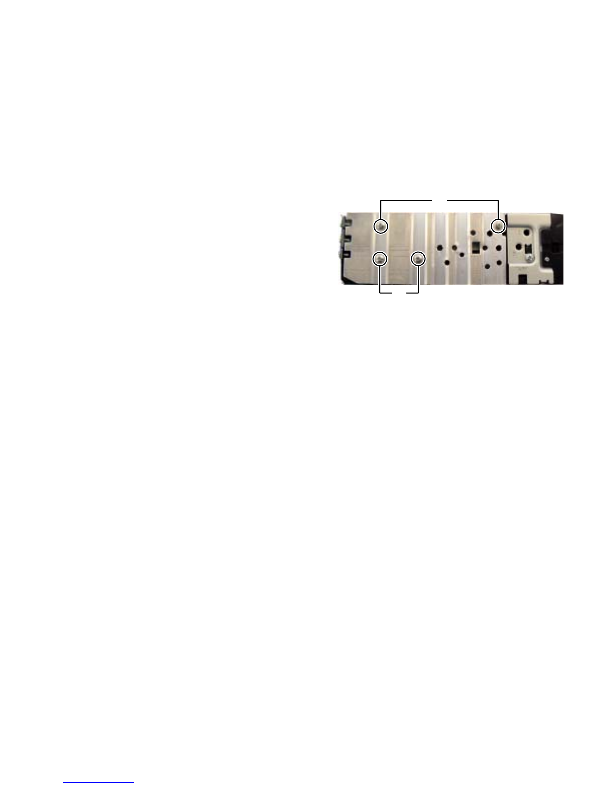
3.1.1 Removing the Heat sink(See Fig.1)
(1) Remove the two screw A and two screws B attaching the
Heat Sink.
A
B
Fig.1
(No.MA401<Rev.001>)1-13
Page 14

3.1.2 Removing the top Chassis(See Fig.2 to 4)
(1) From the side of the main body, remove the two screw C
attaching the both side of Top chassis.(See Fig.2)
(2) From the bottom side of the main body, remove the two
screws D attaching the Top chassis.(See Fig.3)
(3) From the back side of the main body, remove the four
screws E attaching the To p Chassis.(See Fig.4)
C
Fig.2
D
Fig.3
Fig.4
E
1-14 (No.MA401<Rev.001>)
Page 15

3.1.3 Removing the Main board(See Fig.5 and 6)
(1) Remove the two screws F attaching th e Rear bracket. (See
Fig.5)
(2) Disconnect the connector wire from Gear bracket uni t con-
nected to connector CN891 of the main board.(See Fig.6)
(3) Disconnect the connector wire from motor connected to
connector CN881 of the Main board.(See Fig.6)
(4) Disconnect the card wire from Front chassis connected to
connector CN962 of the Main board.(See Fig.6)
(5) Remove the two screws G attaching the Main board.(See
Fig.6)
(6) Slide the Main board to rear side and lift up it, then take out
the Main board.(See Fig.6)
F
Fig.5
CN962CN891
G
CN881
G
3.1.4 Removing the DVD mechanism assembly.(See Fig.7)
(1) Remove the three screws H attaching the D VD mechanis m
assembly.
(2) Disconnect the connector wire from Front chassi s connect-
ed to connector CN399 of the Connection board.
H
CN399
Fig.6
H
H
Fig.7
(No.MA401<Rev.001>)1-15
Page 16

3.1.5 Removing the Connection board assembly(See Fig.8)
(1) Disconnect the card wire from DVD mechanism assembly
connected to connec tor CN1 and CN 395 of the Conn ection
board assembly.
(2) Remove the four screws J attaching the Connection board
assembly.
3.1.6 Removing the Rear cover(See Fig.9)
(1) Remove the nine screws K attaching the Rear cover.
CN1
J
K
CN395
Fig.8
J
K
Fig.9
1-16 (No.MA401<Rev.001>)
Page 17

3.2 DVD mechanism
3.2.1 Removing the Traverse mechanism assembly (See Fig.1 to 6)
(1) Solder the short land section on the flexibl e w ire of pi ck up.
(See Fig.1)
Caution:
* Solder the short land section on the flexible wire of pickup
before disconnecting the flexible wir e form the connector
on the Front end board.
CN101
If the flexible wire is disconnected without attaching the
solder, the pickup may be destroyed by static ele ctri ci ty.
* When attaching the Traverse mechanism assembly, remove the sold er from the sh ort lan d sec tion a fter co nnectio n
the flexible wire to the connector CN101
on the Front end
board.
(2) Voltage supply to TP79 and TP81 approx DC 3.0V until
Clamper is shift to loading complete position. (See Fig.2)
(3) Disconnect the flexible wires from Traverse mechanis m as-
sembly connected to connector CN101
and CN164 of the
Front end board. (See Fig.2)
(4) Remove the five screws A attaching the Top cover assem-
bly. (See Fig.3)
(5) From the bottom side, disconnect the connector wire from
Top cover assembly connected to connector CN2
of the
Front end board. (See Fig.4)
(6) From the bottom side, remove the spring from Traverse
mechanism assembly. (See Fig.5)
(7) From the top side, pull up the traverse mechanism and disengage
three dumper positions. (See Fig.6)
A
Fig.3
CN2
CN164
Fig.1
Fig.2
Solder short part
CN101
R312
R357
TP79
TP79 TP81
R317
TP67
R21
TP92
CENTER
WOOFER
DGND_7
TP81
D-
Voltage supply
position
Fig.4
Fig.5
Dumper
(same color spring)
Dumper
(Different color spring)
Fig.6
(No.MA401<Rev.001>)1-17
Page 18

3.2.2 Removing the Front end board (See Fig.7)
(1) Remove the Motor wires from loading motor soldered to
TP79
and TP81 of the Front end board.
(2) Remove the two screws B attaching the Front end board.
3.2.3 Removing the Loading arm assembly (See Fig.8)
(1) Remove the Loading arm spring L from Loading arm assembly.
(2) Slide to left side and then disengage hook a then hook b.
hook b
B
TP79
Fig.7
TP81
Loading arm
assembly
B
hook
a
Loading arm spring L
Fig.8
1-18 (No.MA401<Rev.001>)
Page 19

3.2.4 Removing the Gear base assembly (See Fig.9, 10)
(1) Remove the Loading arm spring L. (See Fig.9)
(2) Remove the two screws C attaching the Gear base assembly.
(See Fig.10)
Loading arm
spring L
Fig.9
C
3.2.5 Removing the Loading arm holder. (See Fig.11)
(1) Remove the two screws D attaching the Loading arm holder.
(2) Remove the Loading arm spring R.
Fig.10
D
Loading arm
holder
Loading arm
spring R
Fig.11
(No.MA401<Rev.001>)1-19
Page 20

3.2.6 Removing the Loading moor assembly (See Fig.12)
(1) Remove the three screws E attaching the Loading motor
assembly.
3.2.7 Removing the Slide cam assembly (See Fig.13)
(1) Slide to backward the Slide c am as semb ly an d the r em ove
the Slide cam spring.
(2) Slide to frontward the slide cam assembly, and then take
out it.
E
Fig.12
Slide cam assembly
3.2.8 Removing the Photo board (See Fig.14)
(1) Pressing the hook c and then slide to backward (slide to the
arrow side) the Disc pl ate.
(2) Remove the one screw F attaching the Photo board.
Photo board
Slide cam spring
Fig.13
hook
c
Fig.14
hook
F
c
1-20 (No.MA401<Rev.001>)
Page 21

3.2.9 Removing the Loading motor (See Fig.15 to 18)
r
(1) Remove the A wheel gear. (See Fig.15)
(2) Remove the A worm gear, M connect gear and M wheel
gear by sequentially. (See Fig.16)
(3) Remove the two screws G attaching the Loading motor.
(Se Fig.17)
(4) When attaching the Loading motor, motor wire should arrange
to figure. (See Fig.18)
A Wheel gea
Fig.15
A worm gear
M connect gear
M wheel gear
Fig.16
G
Fig.17
Wire arrangement
Fig.18
(No.MA401<Rev.001>)1-21
Page 22

3.2.10 Removing the Roller assembly (See Fig.19)
(1) Remove the Slit washer.
(2) Remove the R middle gear.
(3) Remove the R connect gear.
(4) Snap off the part a of the Roller assembly.
(5) Lift up the part b of the Roller assembly, and then release
part c (When rele ase part c, R coll ar R is ea sy to c ome off ,
does not lose it).
CAUTION:
When reattach the Roller assembly, Middle gear should keep
direction and Slit washer should be change new part.
Direction
R middle gear
R collar R
R connect gear
Slit washer
part c
part a
part b
3.2.11 Removing the Roller (See Fig.20)
(1) Remove the Slit washer.
(2) Pull out the Roller shaft.
CAUTION:
When reattach the Roller shaft, Slit washer should be change
new part.
Fig.19
slit
keep direction
keep direction
slit
1-22 (No.MA401<Rev.001>)
small side
Fig.20
Page 23

SECTION 4
ADJUSTMENT
4.1 Test instruments required for adjustment
(1) Digital oscilloscope (100MHz)
(2) Electric voltmeter
(3) Digital tester
(4) Tracking offset meter
(5) Test Disc : VT501 or VT502
(6) Extension cable : EXTDV002-30P x1
EXTSH002-22P x1
EXTAV70X-50PF x1
(7) Extension studs : STDV001-3P
4.3 Standard volume position
Balance and Bass &Treble volume : lndication"0"
Loudness : OFF
4.4 Dummy load
Exclusive dummy load should be used for AM,and FM.
For FM dummy load, there i s a l oss of 6dB b etw ee n SSG out put
and antenna input.
The loss of 6dB need not be considered sincedirect reading of
figures are applied in this working standard.
4.2 Standard measuring conditions
Power supply voltage DC14.4V(10.5 to 16V)
Load impedance 20K.(2 Speakers connection)
Output Level Line out 2.5V (Vol. MAX)
4.5 How to connect the extension cable for adjusting
Caution:
Be sure to attach the heat sink and rear bracket onto the power amplifier IC and regulator IC respectively,
before supply the power.
If voltage is applied without attaching these parts, the power amplifier IC and regulator IC will be destroyed by heat.
L201
C215
C115
C901
C902
L901
CN901
Q8093
R8103
D984
C8005
Q8095
R858
R8111
C850
PP1
D8067
D8069
Q8098
R857
C845
C8042
R859
C8044
R8059
R8042
C852
R8041
R8108
C8043
Q8042
D901
D8041
D8062
D8061
R8045
C374
R8043
C8048
R8044
CN861
R8062
C182
C373
C8063
C172
R183
C272
R173
C282
C173
C183
C378
C372
C283
C8001
C273
R8002
Q373
R273
Q374
C377
R283
IC371
C863
TH721
Q8092
D8075
D8068
Q8041
L8041
L8011
L8051
R8241
D8003
D8004
D807
D8001
C375
Q372
R374
R8085
IC823
C376
R373
R375
R8084
Q8083
D371
R378
R8082
D8065
Q371
R8091
R8107
Q8097
C9102
R370
R376
D8066
R8104
Q8091
R8214
C8012
Q8011
D8011
L8021
R810
R8083
R820
C8082
Q8001
IC822
R8234
R377
R372
C8031
IC803
D372
Q8096
R8231
R8101
R8232
D8063
R8049
R8048
R8029
R8010
R8102
R8105
C8026
R8011
R8112
Q8094
R8209
R8046
C8047
R8047
C8027
Q8043
C8061
R8061
C8062
Q8013
Q8012
R8052
Q8052
Q8053
R8120
C8013
C8014
C8087
C8086
R8089
C8085
Q8051
R8051
C8058
F801
C8052
Q8023
R8022
D8051
C8054
Q8022
C8022
Q8021
R8021
C831
R8211
C8002
R8210
CN871
R984
C809
R806
R903
C805
C811
C812
C808
R986
Q806
C807
R804
R807
R902
D9002
D8007
C352
C303
C306
C191
R8208
R231
C231
L827
C9214
C192
C391
C292
C9204
C291
C844
R946
R943
Q864
Q863
Q862
R8037
C8035
R866
R942
R8038
C8034
D845
R8033
IC721
R8034
IC941
C942
C8036
C8033
C841
R906
R947
R821
R945 R949
R769
R944
R768
R909
C8018
IC942
R338
R770
R766
R8006
C944
C827
Q955
R330
R971
R955
R956
R972
R973
Q952
Q953
R331
R337
R783
R712
R702
R703
R8063
R704
C8073
R8076
R8053
D731
IC804
R795
C732
C731
R784
IC731
R798
C8071
C715
R8064
R8075
RA721
C716
C8074
X702
C8072
Q8005
R8023
C8075
R8073
C8003
R8074
R781
R709
X701
R710
R738
C701
L701
R737
C702
C713
C800
D974
D975
Q701
D991
D973
D972
IC801
C801
L101
R115
R215
R347
R342
R153
D151
R163
R263
R254
R253
R164
D251
Q251
Q161
Q261
R154
Q151
CN922
R958
D9003
R785
C125
C161
C261
C251
R240
R9997
C307
C151
R130
R152
R162
D190
R323
R324
D191
R151
R161
R230
R311
R140
R303
R305
C304C305
R306
R308
R309
R307
R312
C321
IC350
IC321
C129
C121
C229
C325
Q842
R848
Q844
Q843
C847
Q8002
Q804
Q8006
C721
Q847
Q8007
C848
D844
RA729
R846
R786
R771
C8004
D8002
R767
R774
R773
C8006
R775
D8010
R796
R759
RA725
RA726
R803
R757
RA728
RA727
R735
R736
IC701
R732
RA722
R717
R723
R724
RA723
R728
R714
R713
R716
R715
D969
D966
D968
R960
R965
RA730
D967
C974
D964
D963
D962
R987
C973
TP726
D965
D861
Q341
Q342
R209
C223
R341
R109
R344
R116
R216
C123
R349
R264
Q201
R346
Q101
R110
C323
D342
D340
R262
R252
R251
R261
C206
C7
C113
C345
C106
R325
C124
R125
R113
R340
R348
R119
C224
R328
R329
C326
R219
R322
R225
C5
C324
R9996
C222
C336
C221
C122
D847
D846
C846
R852
C849
R856
Q849
Q845
Q848
C931
CN931
TH700
R932
R7003
D922
R9926
R9925
R700
R779
R790
R765
R7001
D921
C9926
C9925
C9927
R934
R9924
R9923
IC934
R740
C927
IC935
IC933
R739
C923
R924
R925
RA724
R926
R711
C9905
C925
R937
R733
C921
PP2
R756
R962
R730
IC921
R961
C922
R922
R923
R729
R755
D970
R963
D971
D961
TP725
TP722
BZ951
TP721
TP724
TP723
CN962
CN860
CN921
C866
R165
R265
CN911
W1
PP3
R16
D12
C27
R22
C44
L10
L8
C22
R210
C20
R10
R17
C26
L11
L9
D11
L1
L3
C30
C46
C45
C12
C8
R34
C10
R326
C13
IC11
C24
L5
C42
R335
C11
L2
C28
R334
C14
C25
C21
IC332
C19
R14
C9
C29
R352
R336
C213
PP4
L931
R9927
C9906
L842
C41
C16
R15
R21
R35
R213
C23
R98
C17
R99
C18
R20
L6
X1
R19
R23
R36
R11
R39
R9
R18
R38
C31
C37
C38
C36
X31
C34
C33
R13
C35
IC31
C32
R8
CN881
C9930
Q881
IC881
C881
L841
R8113
D808
R8114
C952
CN891
EXTAV70X-50PF
Extension cable
EXTXD001-50PF
EXTDV002-30P
EXTSH002-22P
C3006
C3002
C3004
R3033 R3034
R3035
R3036
R3037
R3038
C3025
C3013
C3014
R3011
R3010
C3135
R3173
R3157
C3141
C3106
C3105
C3024
IC397
C3015
R3007
R3006
CN395
IC399
C3107
C3123
C3125
R3141
R3132
R3135
R3139
R3144
R3134
R3133
R3146
R3142
C3124
R3131
C3130
C3131
C3137
C3136
C3126
C3121
C3115
C3112
R3150
C3133
R3120
R3115
R3127
R3125
R3117
C3117
IC393
IC394
C3129
C3110
C3132
C3108
C3113
R3114
C3111
C313
C3156
5
R3159
R3158
R3172
C3140
R3123
R316
C3118
R3122
R3
Extension studs
STDV001-3P
Extension studs
STDV001-3P
(No.MA401<Rev.001>)1-23
Page 24

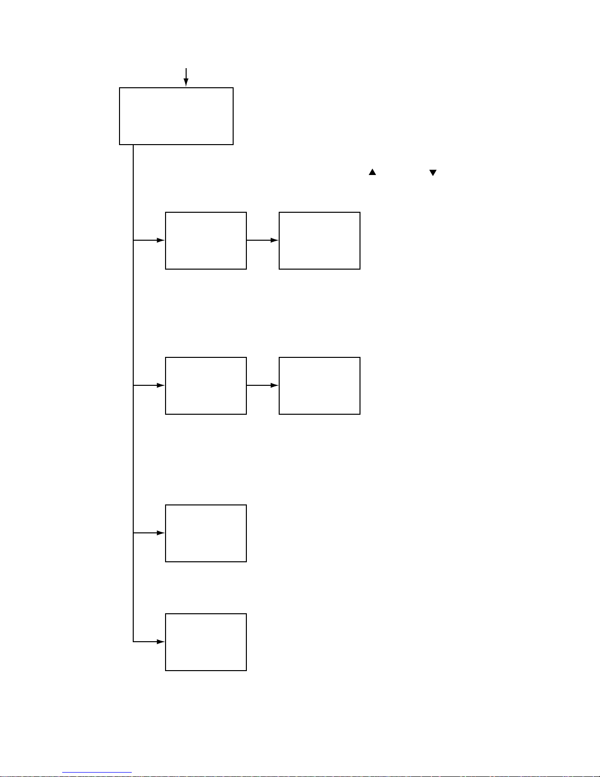
4.6 Service mode
4.6.1 Service mode 1 (Indication of a service mode 1 is nothing.)
Keep this state more 2 seconds
while continuing pressing the
[STANDBY/ON ATTENUATOR] button
and [EJECT] button sequentially.
Screen indication
Exchanging it operate a menu of a service mode with the [ޓ] button
NO EJECT? *–1
EMERGENCY EJECT? *–2
and [ޓ] button. Operate choice of a menu with a [PLAY/PAUSE] button.
*1 : When an [PLAY/PAUSE] button is pushed in NO EJECT indication,
it is set by an EJECT prohibition mode.
When an [PLAY/PAUSE] button is pushed in EJECT OK indication,
it is set by a normal mode.
*2 : Forced EJECT movement
A screen becomes normal indication after an [PLAY/PAUSE] button was pushed.
Multiplex push timing chart (Example: Service mode 2)
[SOURCE]
[EJECT]
[MENU]
[PLAY / PAUSE]
[FOLDER UP]
Within 0.5 seconds
Within 2 seconds
Key ON (Hold)
Key ON (Hold)
Key ON
Within 2 seconds
Key ON
Key ON
Within 2 seconds
Shift to service Mode 2
1-24 (No.MA401<Rev.001>)
Page 25
4.6.2 Service mode 2
Set to service mode 2: [SOURCE]ψ[EJECT]ψ[MENU]ψ[PLAY/PAUSE]ψ[FOLDER UP]
Screen indication
SERVICE MODE 2
INITIALIZE ALL
INITIALIZE
INITIALIZE DVD
INITIALIZE BT
Exchanging it operate a menu of a service mode with the [ޓ] button and [ޓ] button.
Operate choice of a menu with a [PLAY/PAUSE] button.
INITIALIZE ALL
INITIALIZE ALL (Each EEPROM is initialized
ޓby a factory shipment state.)
NOW ...
INITIALIZE ALL
INITIALIZE ALL
OK**
Main micon EEPROM initialization
(user entry domain, error history, speaker
setting, subarea of J-version, data to pre-set )
Panel micon EEPROM initialization
(picture adjustment data)
DVD unit EEPROM initialization
(except a permanent domain)
Bluetooth module EEPROM initialization
After clear completion, a screen returns
to normal indication after OK indication
was displayed for three seconds.
INITIALIZE
INITIALIZE
(Initialization of a user area of each EEPROM)
NOW ...
INITIALIZE
INITIALIZE
OK**
Main micon EEPROM initialization
ޓޓ(a user entry domain )
(a user entry domain, speaker setting,
ޓޓsubarea of J-version, data to pre-set )
Panel micon EEPROM initialization
ޓޓ(picture adjustment data )
DVD unit EEPROM initialization
ޓޓ(except a permanent domain)
After clear completion, a screen returns to
ޓޓ normal indication after OK indication was
ޓdisplayed for three seconds.
INITIALIZE DVD
INITIALIZE DVD
OK**
INITIALIZE BT
INITIALIZE BT
OK**
Full initialization of EEPROM of a DVD unit
( It is included a permanent domain)
After clear completion, this indication is continued till an effective key is input.
Full initialization of EEPROM of Bluetooth
After clear completion, this indication is continued till an effective key is input
(No.MA401<Rev.001>)1-25
Page 26

4.6.3 Service mode 3
Set to service mode 3: [SOURCE]ψ[EJECT]ψ[MENU]ψ[PLAY/PAUSE]ψ[DISP]
Screen indication
SERVICE MODE 3
SERVICE MODE
INTIALIZE ALL
RUNNNING MODE
Exchanging it operate a menu of a service mode with the [ޓ] button
and [ޓ] button. Operate choice of a menu with a [PLAY/PAUSE] button.
SERVICE MODE
SERVICE MODE
VERSION
AREA/REGION
TEMPERATURE
MEMORY CHECK
SERVICE MODE
ERROR READ
ERROR CLEAR
BT VERSION
DVD NTSC/PAL
DVD CHECK MODE
ޓExchanging it operate a menu
of a service mode with the [ޓ]
button and [ޓ] button.
ޓOperate choice of a menu with
a [PLAY/PAUSE] button.
ޓReturn to previous menu with
VERSION
MAIN V**** [**]
ޓDISC ****
CH ******
PANEL V**** V*** [**] V***
a [BAND] button.
Micon version indication
Main micon version and ROM
ޓcorrection version
DVD module version
CH version
Panel micon version and ROM
ޓcorrection version
AREA/REGION
SYS-AREA : *
DISC-AREA : **
REGION : *
Area and region indicattion
Main micon area
DVD area
Region
TEMPERATURE Temperature data reading
ޓTemperature data by the temperature sensor in the main
ޓmicon and DVD-PCB is read every 5 seconds and
displayed in hex numbers.
MEMORY CHECK
( It is displayed only at the time of the disc insertion )
Memory residual quantity indication mode
Data residual quantity of a disc is displayed by LCD.
About the playback control-related key ([FSKIP], [BSKIP],
ޓ[UP], [DOWN], [VOL]), only movement is effective.
Indication does not change as memory residual quantity
indication.
About cancellation of this mode, press the
[STANDBY/ON ATTENUATOR] button.
DVD NTSC/PAL
NTSC
PAL
DVD picture change
DVD module output picture
setting (NTSC)
DVD module output picture
setting (PAL)
1-26 (No.MA401<Rev.001>)
DVD CHECK MODE
See "DVD CHECK MODE" for details.
Page 27

ERROR READ
DVD ERROR READ
CH ERROR READ
MECHA ERROR READ
READ ALL
DVD ERROR READ
Reading of a DVD unit error history
CH ERROR READ
Reading of a CD changer error history
MECHA ERROR READ
Reading of a door mechanism error history
READ ALL
Reading of a main micon EEPROM (All contents)
INITIALIZE ALL
NOW ...
INITIALIZE ALL
ERROR CLEAR
DVD ERROR CLEAR
CH ERROR CLEAR
MECHA ERROR CLEAR
BT VERSION
SW BT CORE ***
HW BT MODULE ***
SW BT MODULE ***
ADR-************
INITIALIZE ALL
OK***
Clear of each error history
A screen returns to following
indication after clear completion.
Bluetooth version indication
Software version of BT core
Hardware version of BT Module
Software version of BT Module
BT Address
INITIALIZE ALL (Each EEPROM
ޓis initialized by a factory shipme nt state.)
Main micon EEPROM initiali zation (user entry domain,error
history,speaker setting, subarea
of J-version, data to pre-set )
Panel micon EEPROM initiali zation (picture adjustment data)
DVD unit EEPROM initialization
(except a permanent domain)
Bluetooth module EEPROM
initialization
After clear completion, a screen
returns to normal indication after
OK indication wasdisplayed for
three seconds.
RUNNING MODE
See "Running mode" for details.
(No.MA401<Rev.001>)1-27
Page 28

4.6.4 Service mode 4
Set to service mode 4: [SOURCE]ޓ[EJECT]ޓ[MENU]ޓ[PLAY/PAUSE]ޓ[REW]
Screen indication
SERVICE MODE 4
RDS S MODE
MONITOR S MODE
HD RADIO S MODE
Exchanging it operate s menu of a service mode with the [ޓ] buttonand [ޓ] button.
Operate choice of a menu with a [PLAY/PAUSE] button.
RDS S MODE
ޓRDS service mode (Only RDS model)
MONITOR S MODE
R/W CHROMA
DATA CLEAR
*See "Monitor adjustment" for details.
CHROMA DATA read/write of NTSC/PAL signal processing IC
Clear of CHROMA DATA (return to an initial value)
4.7 DVD Check Mode
DVD CHECK MODE
NORMAL PLAY
EF OUT-TRACKING OFF
EF IN-TRACKING OFF
CD-LASER ON
DVD-LASER ON
DVDx1 JITTER MODE
DVD CHECK MODE
EEPROM DATA DISP
EEPROM DATA CLEAR
TEMPERATURE
SEARCH & JITTER
MONITOR
PLAY
DVD CHECK MODE
STOP
OPEN
CLOSE
Exchanging it operate a menu of a service mode with the [UP] button
and [DOWN] button. Operate choice of a menu with a [PLAY/PAUSE] button.
Command
NORMAL PLAY Start at normal speed
Mechanism unit operation Indication contents
Laser current value, jitter value
(After start, jitter is measured by an inner position.)
EF OUT-TRACKING OFF Tracking off the outermost position of CD
EF IN-TRACKING OFF
CD-LASER ON
DVD-LASER ON
Tracking off the outermost position of CD
CD_LD lights and laser current is displayed.
DVD_LD lights and laser current is displayed.
For EF phase error
For EF phase error
Laser current value, jitter value
Laser current value, jitter value
Laser current value, jitter valueDVDx1 JITTER MODE DVD x1 jitter measuring mode
(for use in mechanism adjustment)
EEPROM DATA DISP
Contents of EEPROM is displayed.
EEPROM address
EEPROM contents
EEPROM DATA CLEAR
Contents of EEPROM is initialized.
EEPROM address
EEPROM contents
TEMPERATURE Temperature indication Temperature is displayed in hex numbers.
Position measured with VT-501 jitter value.SEARCH & JITTER The search and jitter measurement to an appointed
position of DVD.
MONITOR Monitor terminal setting
PLAY DVD x1 stopped start
(After start, jitter is measured by an inner position.)
STOP
Disc stopped, LD-OFF
OPEN OPEN
CLOSE CLOSE
Not displayed.
Not displayed.
Not displayed.
Not displayed.
1-28 (No.MA401<Rev.001>)
Page 29

4.8 Error code tables
4.8.1 Mechanism error code
Error contents Details Error code
Disc loading error
‡B D1 time out
Eject error
‡B B1 time out
‡C C1 time out
Error in loading wait
4.8.2 Disc error code
Error contents Details
TOC read error
First track access error
Last track access error
T1 access error
T12 access error
T24 access error
Read-in area read error
DVD L1 layer adjustment error
DVD L0 layer adjustment error
NO DISC judgment
It is NO DISC by start failure
It is stopped by playback inability.
Logic format NG
Seek access error
Detailed error code
09 0013
01
01
Loading of a running mode
Disc was pulled out in a wait.
Error code Detailed error code
TOC lead movement of a CD is not completed. 84
Even if TOC reading passes after the end with CD
running mode for 30 seconds, the first track
80
access is not finished.
Even if first track passes after the end with CD
running mode for 30 seconds, the first track
80
access is not finished.
Even if T1 access passes in a DVD runnung
mode for 30 seconds, it is not finished.
Even if T12 access passes in a DVD runnung
mode for 30 seconds, it is not finished.
Even if T24 access passes in a DVD runnung
mode for 30 seconds, it is not finished.
Read-in area read operation of DVD is not
completed.
Adjustment of L1 layer of DVD is not finishhed
normally. (including focus jump failure)
Adjustment of L0 layer of DVD is not finishhed
normally. (including focus jump failure)
Judgment without disc
Start is impossible
Stop in running mode playback
Logic format analysis inability or
non-correspondence logic format
It cannot arrive at an aim address even if it
passes for 15 seconds.
80
80
80
84
80
80
80
80
80
80
80
0023
0024
003109
0059
0060
0061
0069
0070
0071
0072
0074
0075
0090
0091
0093
0094
0095
(No.MA401<Rev.001>)1-29
Page 30

4.8.3 Error codes of panel mechanism
PANEL ANGLE
OpenPanel1
Main Body
1
1
1
10 degrees
20 degrees
30 degrees
Openopen
Detail
(Service mode)
Open error
1. Time out error by OPEN position cannot detect.
Close error (ANGLE 1 error)
1. Time out error by ANGLE 1 position cannot detect.
Angle positioning error
Moving to 10 degrees (ANGLE 2 error)
1. Time out error by ANGLE 2 position cannot detect at moving to open position.
2. Missing to ANGLE 1 and detected ANGLE 2 position at moving to open position.
3. Time out error by ANGLE 2 cannot detect at moving close position.
Moving to 20 degrees (ANGLE 3 error)
1. Time out error by ANGLE 3 position cannot detect at moving to open position.
2. Missing to ANGLE 2 and detected ANGLE 3 position at moving to open position.
3. Time out error by ANGLE 3 cannot detect at moving close position.
Moving to 30 degrees (ANGLE 4 error)
1. Time out error by ANGLE 4 position cannot detect at moving to open position.
2. Missing to ANGLE 3 and detected ANGLE 4 position at moving to open position.
3. Time out error by ANGLE 4 cannot detect at moving close position.
Abnormal switch position at moving panel
The Panel move to open and close position, detected abnormal switch position.
Error code
0A0001
0B0006
0D0021
0D0022
0D0023
0E0031
0E0032
0E0033
0F0041
0F0042
0F0043
0A0000
1-30 (No.MA401<Rev.001>)
Page 31

4.9 Running mode
Indication
RUNNING1 MECHA
RUNNING2 MECHA
RUNNING3 DVD
RUNNING4 DVD
RUNNING5 DVD
RUNNING6 DVD
RUNNING7 DVD
RUNNING8 DVD
Explanation Operation contents of 1 cycle
Door mecha running 1
Door mecha running 2
DVD+Door mecha running1
DVD+Door mecha running2
DVD+Door mecha running3
DVD+Door mecha running4
DVD+Door mecha running5
DVD+Door mecha running6
Panel close Panel open
Panel close Panel open Panel detach position Panel angle
3 position Panel angle 1 position Panel angle 2 position
Loading Eject Wait for 5 seconds+Door open/close
Loading Eject Wait for 5 seconds+Door open/close
Loading Playback Eject Wait for 5 seconds+Door open/close
Loading Playback Eject Wait for 5 seconds+Door open/close
Loading Playback Eject Wait for 5 seconds+Door open/close
Loading Playback Eject Wait for 5 seconds+Door open/close
RETRY
NO RETRY
In Mecha error In disc error
--
Retly
Stop
Stop
Retly
Stop
Retly
Stop
Retly Retly
Retly
* Cancellation of running1,2 : Press the [EJECT] key
* In running 1,2 cancellation, a door does not stop at the position and moves to a panel position.
* Cancellation of running3 to 8 : Press the [POWER] key
* The number of count and an error cord are displayed in running.
Playback contents in a running mode
•CD
The first track is played for 30 seconds.→The last track is played for 30 seconds.
(The last track is played in the case of less than till the last for 30 seconds.)
•DVD
2layer disc (Pit disc)
Title 1 (the L0 layer internal circumference) is played for 30 seconds.→ Title 12 (L0 layer circumference) is play ed for 30 seconds.
→ Title 24 (L1layer internal circumference) is played for 30 seconds.
2layer disc (Recordable disc)
Title 1 (the L0 layer intern al circumferenc e) is played for 30 seconds.→ Title 1 3 (L0 layer circum ference) is play ed for 30 seconds
→Title 24 (L1layer internal circumference) is played for 30 seconds.
-
-
-
-
Stop
Stop
1layer disc
First chapter of title 1 is played for 30 seconds. → The last chapter of title 1 is played for 30 seconds.
4.10 Monitor adjustment
* When adjusting, switch on the main unit and insert a test disc (VT-501). And play the test disc and pause it.
(1) Set the service mode 4.
(2) Exchanging it operate a menu of a service mode with the [UP] button and [DOWN] button.
(3) Change data with the [B.SKIP]/[F.SKIP] buttons.
(4) Write data with a [PLAY/PAUSE] button.
Indication
00001
00002
00003
00004
00005
00006
00007
00008
00009
00010
00011
00012
00013
00014
00015
00016
00017
Minimum value Maximum value
00000
00000
00000
00000
00000
00000
00000
00000
00000
00000
00000
00000
00000
00000
00000
00000
00000
00001
00003
00063
00003
00063
00001
00001
00511
00511
00255
00255
00255
00255
00255
00255
00003
00003
Initial value Reference register value
00000
00001
00016
00001
00010
00000
00001
00176
00128
00040
00040
00010
00010
00000
00000
00000
00000
00000
00001
00016
00001
00010
00000
00001
00176
00128
00040
00040
00010
00010
00000
00000
00000
00000
Fix
Fix
Fix
Fix
Fix
Fix
Fix
Fix
Fix
Adjust
Adjust
Adjust
Adjust
Adjust
Adjust
Adjust
Adjust
Detail
Color amplitude revision ON/OFF
Color amplitude revision CAS
Color amplitude revision APC
Color amplitude revision CUS
Color amplitude revision APU
Black level extension ON/OFF
Black level extension FUNCTION
Black level extension START POINT
Black level extension OFFSET
Enhancer revision effect adjustment (NTSC)
Enhancer revision effect adjustment (PAL)
Limiter of the horizontal enhancer (NTSC)
Limiter of the horizontal enhancer (PAL)
Filter choice of the horizontal enhancer (NTSC)
Filter choice of the horizontal enhancer (PAL)
Tap change of the brightness outline revision (NTSC)
Tap change of the brightness outline revision (PAL)
(No.MA401<Rev.001>)1-31
Page 32

Indication
00018
00019
00020
00021
00022
00023
00024
00025
00026
00027
00028
00029
00030
00031
00032
00033
00034
00035
00036
00037
00038
00039
00040
00041
00042
00043
00044
00045
00046
00047
00048
00049
00050
00051
00052
00053
00054
00055
00056
00057
00058
00059
00060
00061
00062
00063
00064
00065
00066
00067
00068
00069
00070
00071
00072
00073
00074
00075
00076
00077
00078
00079
00080
Minimum value Maximum value
00000
00000
00000
00000
00000
00000
00000
00000
00000
00000
00000
00000
00000
00000
00000
00000
00000
00000
00000
00000
00000
00000
00000
00000
00000
00000
00000
00000
00000
00000
00000
00000
00000
00000
00000
00000
00000
00000
00000
00000
00000
00000
00000
00000
00000
00000
00000
00000
00000
00000
00000
00000
00000
00000
00000
00000
00000
00000
00000
00000
00000
00000
00000
00127
00127
00006
00006
00255
00255
00255
00255
00255
00255
00255
00255
00511
00511
00001
00255
01023
01023
00511
00255
00255
00255
00511
00001
00001
00127
00127
00127
00127
00127
00127
00127
00127
00127
00127
00127
00127
00127
00127
00001
00255
00255
00255
00255
00255
00255
00255
00255
00255
00255
00255
00255
00255
00255
00255
00255
00255
00255
00255
00255
00255
00255
00255
Initial value Reference register value
00000
00000
00003
00003
00128
00128
00128
00128
00125
00132
00033
00033
00064
00064
00000
00016
00495
00510
00359
00227
00218
00199
00261
00001
00001
00026
00026
00050
00050
00050
00050
00050
00050
00057
00057
00057
00057
00057
00057
00001
00004
00008
00012
00016
00020
00024
00028
00035
00035
00035
00035
00035
00035
00035
00035
00004
00008
00012
00016
00020
00024
00028
00035
00000
00000
00003
00003
00128
00128
00128
00128
00125
00132
00036
00033
00064
00064
00000
00016
00476
00493
00359
00227
00218
00199
00261
00001
00001
00026
00026
00050
00050
00050
00050
00050
00050
00057
00057
00057
00057
00057
00057
00001
00004
00008
00012
00016
00020
00024
00028
00035
00035
00035
00035
00035
00035
00035
00035
00004
00008
00012
00016
00020
00024
00028
00035
Adjust
Adjust
Adjust
Adjust
Fix
Fix
Fix
Fix
Adjust
Adjust
Adjust
Adjust
Fix
Fix
Fix
Fix
Adjust
Adjust
Fix
Fix
Fix
Fix
Fix
Fix
Fix
Adjust
Adjust
Fix
Fix
Fix
Fix
Fix
Fix
Fix
Fix
Fix
Fix
Fix
Fix
Fix
Fix
Fix
Fix
Fix
Fix
Fix
Fix
Fix
Fix
Fix
Fix
Fix
Fix
Fix
Fix
Fix
Fix
Fix
Fix
Fix
Fix
Fix
Fix
Detail
Adjustment of the quantity of brightness outline core ring (NTSC)
Adjustment of the quantity of brightness outline core ring (PAL)
Adjustment of the brightness outline revision gain (NTSC)
Adjustment of the brightness outline revision gain (PAL)
Change in TINT of the whole picture (NTSC)
Change in TINT of the whole picture (PAL)
Change with the deepness of the color of the whole picture (NTSC)
Change with the deepness of the color of the whole picture (PAL)
Tint adjustment (NTSC)
Tint adjustment (PAL)
Color adjustment (NTSC)
Color adjustment (PAL)
Set the offset DC of the input video signal (NTSC)
Set the offset DC of the input video signal (PAL)
Quantity of transmission revision of the YUV DC
Quantity of transmission revision of the YUV DC
Contrast adjustment between the black - white (NTSC)
Contrast adjustment between the black - white (PAL)
Conversion coefficients from YUV to RGB (PRCL)
Conversion coefficients from YUV to RGB (PBCL)
Conversion coefficients from YUV to RGB (YCL)
Conversion coefficients from YUV to RGB (BCL)
Conversion coefficients from YUV to RGB (RCL)
Noise shaving (NTSC)
Noise shaving (PAL)
Black level adjustment (NTSC)
Black level adjustment (PAL)
Gain setting of Red signal (NTSC)
Gain setting of Red signal (PAL)
Gain setting of Green signal (NTSC)
Gain setting of Green signal (PAL)
Gain setting of Blue signal (NTSC)
Gain setting of Blue signal (PAL)
Set the cut-off of the Red signal (NTSC)
Set the cut-off of the Red signal (PAL)
Set the cut-off of the Green signal (NTSC)
Set the cut-off of the Green signal (PAL)
Set the cut-off of the Blue signal (NTSC)
Set the cut-off of the Blue signal (PAL)
ON/OFF change of the gamma revision
Adjust 1 gamma revision point position of a Red signal
Adjust 2 gamma revision point position of a Red signal
Adjust 3 gamma revision point position of a Red signal
Adjust 4 gamma revision point position of a Red signal
Adjust 5 gamma revision point position of a Red signal
Adjust 6 gamma revision point position of a Red signal
Adjust 7 gamma revision point position of a Red signal
Appoint gamma revision gain 1 of the Red signal
Appoint gamma revision gain 2 of the Red signal
Appoint gamma revision gain 3 of the Red signal
Appoint gamma revision gain 4 of the Red signal
Appoint gamma revision gain 5 of the Red signal
Appoint gamma revision gain 6 of the Red signal
Appoint gamma revision gain 7 of the Red signal
Appoint gamma revision gain 8 of the Red signal
Adjust 1 gamma revision point position of a Green signal
Adjust 2 gamma revision point position of a Green signal
Adjust 3 gamma revision point position of a Green signal
Adjust 4 gamma revision point position of a Green signal
Adjust 5 gamma revision point position of a Green signal
Adjust 6 gamma revision point position of a Green signal
Adjust 7 gamma revision point position of a Green signal
Appoint gamma revision gain 1 of the Green signal
1-32 (No.MA401<Rev.001>)
Page 33

Indication
00081
00082
00083
00084
00085
00086
00087
00088
00089
00090
00091
00092
00093
00094
00095
00096
00097
00098
00099
00100
00101
00102
00103
00104
00105
00106
00107
00108
00109
00110
00111
00112
00113
00114
00115
00116
00117
00118
00119
00120
00121
00122
00123
00124
00125
00126
00127
00128
00129
00130
00131
00132
00133
00134
00135
00136
00137
00138
00139
00140
00141
Minimum value Maximum value
00000
00000
00000
00000
00000
00000
00000
00000
00000
00000
00000
00000
00000
00000
00000
00000
00000
00000
00000
00000
00000
00000
00000
00000
00000
00000
00000
00000
00000
00000
00000
00000
00000
00000
00000
00000
00000
00000
00000
00000
00000
00000
00000
00000
00000
00000
00000
00000
00000
00000
00000
00000
00000
00000
00000
00000
00000
00000
00000
00000
00000
00255
00255
00255
00255
00255
00255
00255
00255
00255
00255
00255
00255
00255
00255
00255
00255
00255
00255
00255
00255
00255
00255
00255
00255
00255
00255
00127
00127
00007
00007
00003
00003
00007
00007
00007
00007
01023
01023
00063
00063
01023
01023
00255
00255
00511
00511
00006
00255
00255
16383
16383
00127
00015
00063
00063
65535
65535
00063
00015
00015
00015
Initial value Reference register value
00035
00035
00035
00035
00035
00035
00035
00004
00008
00012
00016
00020
00024
00028
00035
00035
00035
00035
00035
00035
00035
00035
00106
00112
00020
00028
00042
00042
00001
00001
00048
00048
00000
00000
00001
00001
00180
00180
00000
00000
00320
00320
00176
00176
00128
00128
00004
00160
00160
00220
00212
00071
00015
00049
00049
14976
14976
00055
00010
00007
00000
00035
00035
00035
00035
00035
00035
00035
00004
00008
00012
00016
00020
00024
00028
00035
00035
00035
00035
00035
00035
00035
00035
00106
00112
00020
00028
00042
00042
00001
00001
00048
00048
00000
00000
00001
00001
00180
00180
00000
00000
00320
00320
00176
00176
00128
00128
00004
00160
00160
00220
00212
00071
00015
00049
00049
14976
14976
00055
00010
00007
00000
Fix
Fix
Fix
Fix
Fix
Fix
Fix
Fix
Fix
Fix
Fix
Fix
Fix
Fix
Fix
Fix
Fix
Fix
Fix
Fix
Fix
Fix
Adjust
Adjust
Adjust
Adjust
Fix
Fix
Fix
Fix
Fix
Fix
Fix
Fix
Adjust
Adjust
Fix
Fix
Adjust
Adjust
Fix
Fix
Fix
Fix
Adjust
Adjust
Fix
Fix
Fix
Fix
Fix
Fix
Fix
Fix
Fix
Fix
Fix
Fix
Fix
Fix
Fix
Detail
Appoint gamma revision gain 2 of the Green signal
Appoint gamma revision gain 3 of the Green signal
Appoint gamma revision gain 4 of the Green signal
Appoint gamma revision gain 5 of the Green signal
Appoint gamma revision gain 6 of the Green signal
Appoint gamma revision gain 7 of the Green signal
Appoint gamma revision gain 8 of the Green signal
Adjust 1 gamma revision point position of a Blue signal
Adjust 2 gamma revision point position of a Blue signal
Adjust 3 gamma revision point position of a Blue signal
Adjust 4 gamma revision point position of a Blue signal
Adjust 5 gamma revision point position of a Blue signal
Adjust 6 gamma revision point position of a Blue signal
Adjust 7 gamma revision point position of a Blue signal
Appoint gamma revision gain 1 of the Blue signal
Appoint gamma revision gain 2 of the Blue signal
Appoint gamma revision gain 3 of the Blue signal
Appoint gamma revision gain 4 of the Blue signal
Appoint gamma revision gain 5 of the Blue signal
Appoint gamma revision gain 6 of the Blue signal
Appoint gamma revision gain 7 of the Blue signal
Appoint gamma revision gain 8 of the Blue signal
Adjust the horizontal indication point of the picture (NTSC)
Adjust the horizontal indication point of the picture (PAL)
Adjust the vertical indication point of the picture (NTSC)
Adjust the vertical indication point of the picture (PAL)
AD clock gain adjustment (NTSC)
AD clock gain adjustment (PAL)
Noise reduction of the Y signal (NTSC)
Noise reduction of the Y signal (PAL)
Choose a YC separation filter (NTSC)
Choose a YC separation filter (PAL)
Color pulling out filter setting (NTSC)
Color pulling out filter setting (PAL)
Choose com movement mode and color BPF (NTSC)
Choose com movement mode and color BPF (PAL)
Vertical dot cancellation setting (NTSC)
Vertical dot cancellation setting (PAL)
Noise reduction setting (NTSC)
Noise reduction setting (PAL)
Quantity of brightness adjustment setting (NTSC)
Quantity of brightness adjustment setting (PAL)
Brightness gain adjustment (NTSC)
Brightness gain adjustment (PAL)
Color signal output level setting (NTSC)
Color signal output level setting (PAL)
ACC movement mode setting
C signal filter characteristic setting of the Y/C separation part (NTSC)
C signal filter characteristic setting of the Y/C separation part (PAL)
Amplitude killer off level setting
Amplitude killer on level setting
Clamp DC level adjustment setting
Clamp speed adjustment setting
Noise filter band setting of horizontal synchronization
signal and vertical synchronizing signal (NTSC)
Noise filter band setting of horizontal synchronization
signal and vertical synchronizing signal (PAL)
Horizontal phase comparison gain setting (NTSC)
Horizontal phase comparison gain setting (PAL)
Horizontal loop filter setting 1
Horizontal loop filter setting 2
Horizontal loop filter setting 3
Synchronization separation burst clock setting (NTSC)
(No.MA401<Rev.001>)1-33
Page 34

Indication
00142
00143
00144
00145
00146
00147
00148
00149
00150
00151
00152
00153
00154
00155
00156
00157
00158
00159
00160
00161
00162
00163
00164
00165
Minimum value Maximum value
00000
00000
00000
00000
00000
00000
00000
00000
00000
00000
00000
00000
00000
00000
00000
00000
00000
00000
00000
00000
00040
00040
00000
00000
00015
00255
00255
00511
00511
00511
00026
00026
00255
00255
00255
00255
00255
00255
00255
00255
00255
00255
00009
00009
00110
00110
00007
00007
Initial value Reference register value
00129
00252
00252
00326
00082
00033
00000
00000
00000
00000
00000
00000
00018
00020
00082
00082
00087
00087
00004
00006
00090
00060
00000
00000
00129
00252
00252
00326
00082
00033
00000
00000
00000
00000
00000
00000
00018
00020
00082
00082
00087
00087
00004
00006
00090
00060
00000
00000
Fix
Fix
Fix
Fix
Fix
Fix
Fix
Fix
Fix
Fix
Fix
Fix
Adjust
Adjust
Adjust
Adjust
Adjust
Adjust
Fix
Fix
Fix
Fix
Fix
Fix
Detail
Synchronization separation burst clock setting (PAL)
Free run center value setting of horizontal
synchronization signal (NTSC)
Free run center value setting of horizontal
synchronization signal (PAL)
DOKIDET 01
DOKIDET 02
DOKIDET 03
Unused
Unused
Subcareer center frequency setting (NTSC)
Unused
Subcareer center frequency setting (PAL)
Unused
Coordinate the delay of the C signal with a Y signal (NTSC)
Coordinate the delay of the C signal with a Y signal (PAL)
Coordinate the VCOM amplitude of the LCD (NTSC)
Coordinate the VCOM amplitude of the LCD (PAL)
Coordinate VCOM center value of the LCD (NTSC)
Coordinate VCOM center value of the LCD (PAL)
Set a variable range of the indication VSYNC frequency (NTSC)
Set a variable range of the indication VSYNC frequency (PAL)
Set time when indication VSYNC frequency changes (NTSC)
Set time when indication VSYNC frequency changes (PAL)
CLAMP MODE (NTSC)
CLAMP MODE (PAL)
1-34 (No.MA401<Rev.001>)
Page 35

SECTION 5
TROUBLESHOOTING
5.1 16 PIN CORD DIAGRAM (For Northern America, Asia)
GN
VI
BL
RD
BK
WH
WH/BK
GY/BK
GY
BR
YG
OR/WH
YL
GY
BR
YG
OR
YL
9
10
11
12
13
14
15
16
Gray
Brown
YellowGreen
Orange
Yellow
BK
RD
BL
WH
VI
GN
1
8
7
6
5
4
3
2
1
Black
Red
Blue
White
Violet
Green
BK
GN/BK
VI/BK
BL/WH
CONNECTOR
16PIN MOLEX
LOCKING THE WIRE WITH INSULOK
YL1
BATT
DIMENSION CASE
YL1
YL2
YL1 YL2
SET
VIEW TOP
VIEW SIDE
YL2
WIRE CUT
YL1
16
YL2
RD
2
OR/WH
15
BL/WH
3
BR
13
BL
4
GY
12
GY/BK
11
VI
5
VI/BK
6
WH
9
WH/BK
10
GN
8
GN/BK
7
YG
14
(No.MA401<Rev.001>)1-35
Page 36
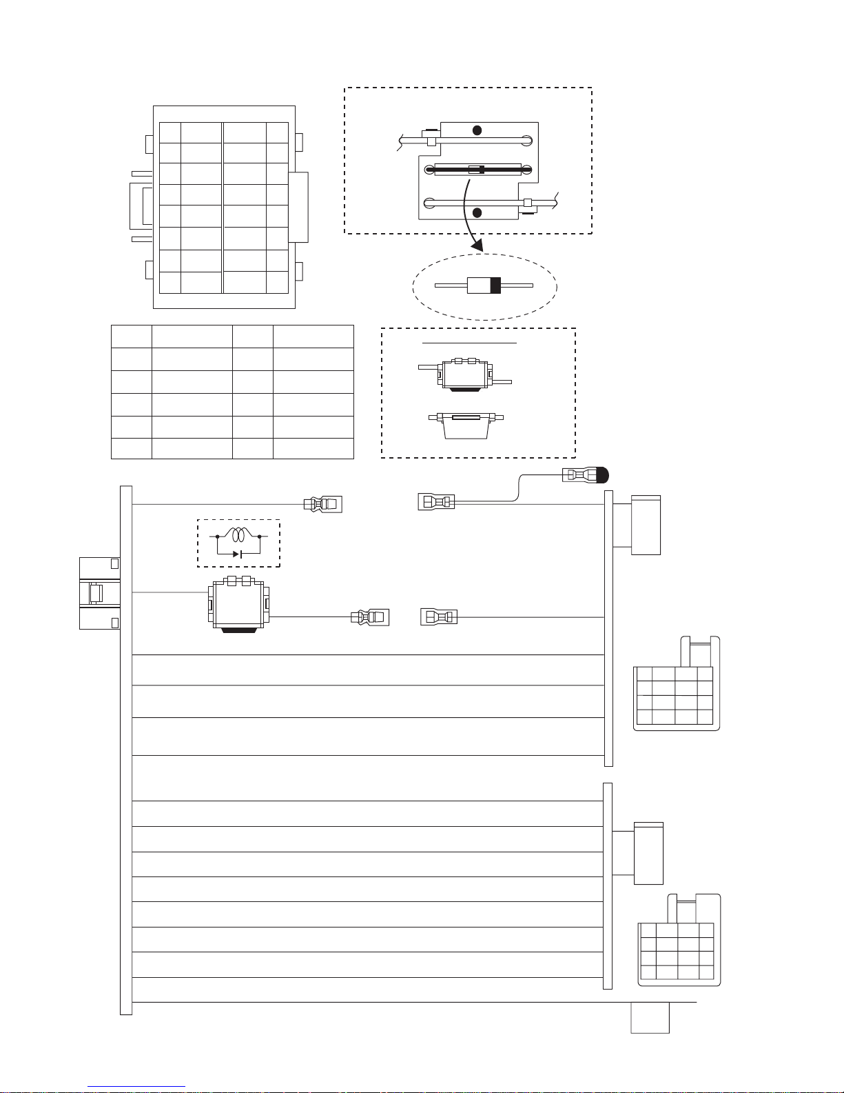
5.2 16 PIN CORD DIAGRAM (For Europe)
VI
WH
WH/BK
GY/BK
GY
BR
YG
OR/WH
YL
9
10
11
12
13
14
15
16
8
7
6
5
4
3
2
1
GN
GN/BK
VI/BK
NC
BL/WH
RD
BK
LOCKING THE WIRE WITH INSULOK
CONNECTOR
16PIN MOLEX
YL2
BATT
SET
YL3
300501-2
BK
RD
BL
WH
VI
GN
2
16
1
3
BR
13
RD1
YL2
BK
BL/WH
Black
Red
Blue
White
Violet
Green
Gray
GY
BR
Brown
YG
YellowGreen
Orange
OR
YL
Yellow
YL3
DIMENSION CASE
YL2
YL2 YL3
RD3
VIEW TOP
YL3
VIEW SIDE
RD2
7
YL 1
4
8
1
5
2
NC
NC
3
BL/WH
5
7
RD
BR
YL
OR/WH
BK
2
4
6
8
OR/WH
15
GN
8
GN/BK
7
VI
5
VI/BK
6
WH
9
WH/BK
10
GY
12
GY/BK
11
YG
14
1-36 (No.MA401<Rev.001>)
6
7
6
1
2
5
8
3
4
VI/BK
VI
1
GY
3
5
WH
GN
7
GY/BK
WH/BK
GN/BK
2
4
6
8
Page 37

(No.MA401<Rev.001>)1-37
Page 38

Victor Company of Japan, Limited
Mobile Entertainment Business Group Mobile Entertainment Category 10-1,1chome,Ohwatari-machi,Maebashi-city,371-8543,Japan
(No.MA401<Rev.001>)
Printed in Japan
VPT
 Loading...