

Page 1
52198200311
SERVICE MANUAL
COLOUR TELEVISION
HV-29WH21, HV-29WH21/A,
HV-29WH21/E, HV-29WH51/S,
RM-C1351
[HV-29WH21]
[HV-29VH21]
RM-C1353
[HV-29WH51]
RM-C1350
[HV-29WH71]
HV-29WH71
[HV-29WH21]
[HV-29WH51]
[HV-29WH71]
/G
BASIC CHASSIS
ML
[HV-29VH21]
TABLE OF CONTENTS
1 PRECAUTION. . . . . . . . . . . . . . . . . . . . . . . . . . . . . . . . . . . . . . . . . . . . . . . . . . . . . . . . . . . . . . . . . . . . . . . . . 1-3
2 SPECIFIC SERVICE INSTRUCTIONS. . . . . . . . . . . . . . . . . . . . . . . . . . . . . . . . . . . . . . . . . . . . . . . . . . . . . . 1-4
3 DISASSEMBLY . . . . . . . . . . . . . . . . . . . . . . . . . . . . . . . . . . . . . . . . . . . . . . . . . . . . . . . . . . . . . . . . . . . . . . . 1-7
4 ADJUSTMENT . . . . . . . . . . . . . . . . . . . . . . . . . . . . . . . . . . . . . . . . . . . . . . . . . . . . . . . . . . . . . . . . . . . . . . . 1-13
5 TROUBLESHOOTING . . . . . . . . . . . . . . . . . . . . . . . . . . . . . . . . . . . . . . . . . . . . . . . . . . . . . . . . . . . . . . . . . 1-32
COPYRIGHT © 2003 VICTOR COMPANY OF JAPAN, LIMITED
No.52198
2003/11
Page 2
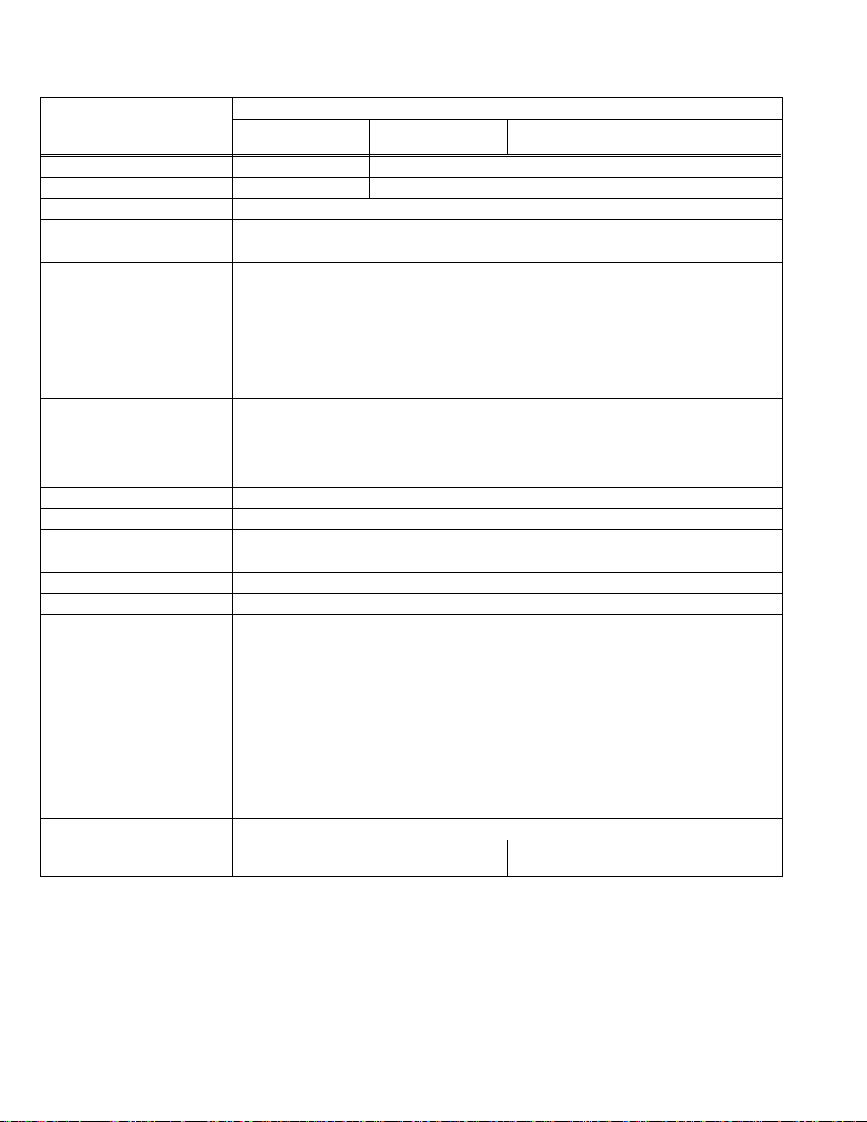
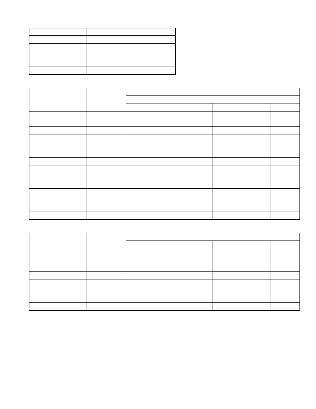
SPECIFICATION
Contents
Items
Dimensions (W × H × D)
Mass 44.5kg 43.6kg
TV RF System B/G, I, D/K, K1, M
Colour System PAL / SECAM / NTSC 3.58 / NTSC 4.43
Stereo System A2 (B/G) / NICAM (B/G, I, D/K)
Teletext System Fastext (UK system)
Receiving
Frequency
Intermediate
Frequency
Colour
Sub Carrier
Frequency
Aerial Input Terminal 75Ω unbalanced, coaxial
Power Input AC 110V~240V , 50/60Hz
Power Consumption Avg.150W
Picture Tube Visible size : 67.6cm (Diagonal) / 54.1cm × 40.6cm (H × V)
High Voltage 31.5kV +1.0kV / -1.5kV (At zero beam current)
Speaker 6.5cm × 13cm Oval type × 2
Audio Power Output 10W + 10W
Video / Audio
Input
Component Video
Video / Audio
Output
Headphone 3.5mm stereo mini jack × 1
Remote Control Unit RM-C1351
VHF Low
VHF High
UHF
CATV
VIF
SIF
PAL
SECAM
NTSC
S-Video
[VIDEO-1]
Video
Audio(L/R)
[VIDEO-3]
Video
Audio(L/R)
HV-29VH21/A
81.2cm × 58.5cm × 52.1cm
WST(world standard teletext system)
46.25MHz ~168.25MHz
175.25MHz ~ 463.25MHz
471.25MHz ~ 863.25MHz
Mid : X-Z+2, S1~S10
Super : S11~S20
Hyper : S21~S41
38.0MHz
32.5MHz(5.5MHz) / 32.0MHz(6.0MHz) / 3.15MHz(6.5MHz) / 33.5MHz (4.5MHz)
4.43MHz
4.40625MHz / 4.25MHz
3.58MHz / 4.43MHz
Mini-DIN 4 pin connector × 1
Y : 1V(p-p), Positive (Negative sync provided), 75Ω
C : 0.286V(p-p) (burst signal), 75Ω
1V(p-p), negative sync, 75Ω, RCA pin jack × 4
500mV(rms) (-4dBs), High impedance, RCA pin jack × 8
RCA pin jack × 3
Y : 1V(p-p), 75Ω
CB : 0.7V(p-p), 75Ω
CR : 0.7V(p-p), 75Ω
1V(p-p) 75Ω, RCA pin jack × 1
500mV(rms) (-4dBs), Low impedance, RCA pin jack × 2
(AA/R06/UM-3 battery × 2)
HV-29WH21
HV-29WH21/E
81.2cm × 58.5cm × 51.8cm
RM-C1350
(AA/R06/UM-3 battery × 2)
HV-29WH71/G HV-29WH51/S
NON
RM-C1353
(AA/R06/UM-3 battery × 2)
Design & specifications are subject to change without notice.
1-2 (No.52198)
Page 3

SECTION 1
PRECAUTION
1.1 SAFETY PRECAUTIONS
(1) The design of this product contains special hardware,
many circuits and components specially for safety
purposes. For continued protection, no changes should be
made to the original design unless authorized in writing by
the manufacturer. Replacement parts must be identical to
those used in the original circuits. Service should be
performed by qualified personnel only.
(2) Alterations of the design or circuitry of the products should
not be made. Any design alterations or additions will void
the manufacturer's warranty and will further relieve the
manufacturer of responsibility for personal injury or
property damage resulting therefrom.
(3) Many electrical and mechanical parts in the products have
special safety-related characteristics. These
characteristics are often not evident from visual inspection
nor can the protection afforded by them necessarily be
obtained by using replacement components rated for
higher voltage, wattage, etc. Replacement parts which
have these special safety characteristics are identified in
the parts list of Service manual. Electrical components
having such features are identified by shading on the
schematics and by ( ) on the parts list in Service
manual. The use of a substitute replacement which does
not have the same safety characteristics as the
recommended replacement part shown in the parts list of
Service manual may cause shock, fire, or other hazards.
(4) Don't short between the LIVE side ground and
ISOLATED (NEUTRAL) side ground or EARTH side
ground when repairing.
Some model's power circuit is partly different in the GND.
The difference of the GND is shown by the LIVE : ( ) side
GND, the ISOLATED (NEUTRAL) : ( ) side GND and
EARTH : ( ) side GND.
Don't short between the LIVE side GND and ISOLATED
(NEUTRAL) side GND or EARTH side GND and never
measure the LIVE side GND and ISOLATED (NEUTRAL)
side GND or EARTH side GND at the same time with a
measuring apparatus (oscilloscope etc.). If above note will
not be kept, a fuse or any parts will be broken.
(5) If any repair has been made to the chassis, it is
recommended that the B1 setting should be checked or
adjusted (See B1 POWER SUPPLY check).
(6) The high voltage appli ed to the picture tube must confo rm
with that specified in Service manual. Excessive high
voltage can cause an increase in X-Ray emission, arcing
and possible component damage, therefore operation
under excessive high voltage conditions should be kept to
a minimum, or should be prevented. If severe arcing
occurs, remove the AC power immediately and determine
the cause by visual inspection (incorrect installation,
cracked or melted high voltage harness, poor soldering,
etc.). To maintain the proper minimum level of soft X-Ray
emission, components in the high voltage circuitry
including the picture tube must be the exact replacements
or alternatives approved by the manufacturer of the
complete product.
(7) Do not check high voltage by d rawing an arc. Use a high
voltage meter or a high voltage probe with a VTVM.
Discharge the picture tube before attempting meter
connection, by connecting a clip lead to the gr ound frame
and connecting the other end of the lead through a 10kΩ
2W resistor to the anode button.
(8) When service is required, obse rve the original lead dress.
Extra precaution should be given to assure correct lead
dress in the high voltage circuit area. Where a short circuit
has occurred, those components that indicate evidence of
overheating should be replaced. Always use the
manufacturer's replacement components.
(9) Isolation Check (Safety for Electrical Shock Hazard)
After re-assembling the product, always perform an
isolation check on the exposed metal parts of the cabinet
(antenna terminals, video/audio input and output terminals,
Control knobs, metal cabinet, screw heads, earphone jack,
control shafts, etc.) to be sure the product is safe to operate
without danger of electrical shock.
a) Dielectric Strength Test
The isolation between the AC primary circuit and all metal
parts exposed to the user, particularly any exposed metal
part having a return path to the chassis should withstand a
voltage of 3000V AC (r.m.s.) for a period of one second. (.
. . . Withstand a voltage of 1100V AC (r.m.s.) to an
appliance rated up to 120V, and 3000V AC (r.m.s.) to an
appliance rated 200V or more, for a period of one second.)
This method of test requires a test equipment not generally
found in the service trade.
b) Leakage Current Chec k
Plug the AC line cord directly into the AC outlet (do not use
a line isolation transformer during this check.). Using a
"Leakage Current Tester", measure the leakage current
from each exposed metal part of the cabinet, particularly
any exposed metal part having a return path to the chassis,
to a known good earth ground (water pipe, etc.). Any
leakage current must not exceed 0.5mA AC (r.m.s.).
However, in tropical area, this must not exceed 0.2mA AC
(r.m.s.).
Alternate Check Method
Plug the AC line cord directly into the AC outlet (do not
use a line isolation transformer during this check.). Use
an AC voltmeter having 1000Ω per volt or more
sensitivity in the following manner. Connect a 1500Ω
10W resistor paralleled by a 0.15µF AC-type capacitor
between an exposed metal part and a known good earth
ground (water pipe, etc.). Measure the AC voltage
across the resistor with the AC voltmeter. Move the
resistor connection to each exposed metal part,
particularly any exposed metal part having a return path
to the chassis, and measure the AC voltage ac ross the
resistor. Now, reverse the plug in the AC outlet and
repeat each measurement. Any voltage measured must
not exceed 0.75V AC (r.m.s.). This corresponds to
0.5mA AC (r.m.s.).
However, in tropical area, this must not exceed 0.3V AC
(r.m.s.). This corresponds to 0.2mA AC (r.m.s.).
AC VOLTMETER
(HAVING 1000 /V,
OR MORE SENSITIVITY)
0.15 F AC-TYPE
PLACE THIS PROBE
1500 10W
GOOD EARTH GROUND
ON EACH EXPOSED
METAL PART
(No.52198)1-3
Page 4
SECTION 2
SPECIFIC SERVICE INSTRUCTIONS
2.1 FEATURES
• New chassis design enable use of an interactive on-screen control.
• The TELETEXT SYSTEM has a built-in FASTEXT (UK system), and WST (world standard teletext system).
[Only HV-29WH21, HV-29WH21/E, HV-29VH21/A, HV-29WH71/G]
• Pure FLAT CRT reproduce fine textured.
• Digi Pure pro : Auto digi pure with motion picture compensation.
• Because this TV unit corresponds to multiplex broadcast, users can enjoy music programs and sporting events with live realism.
In addition, BILINGUAL programs can be heard in their original language.
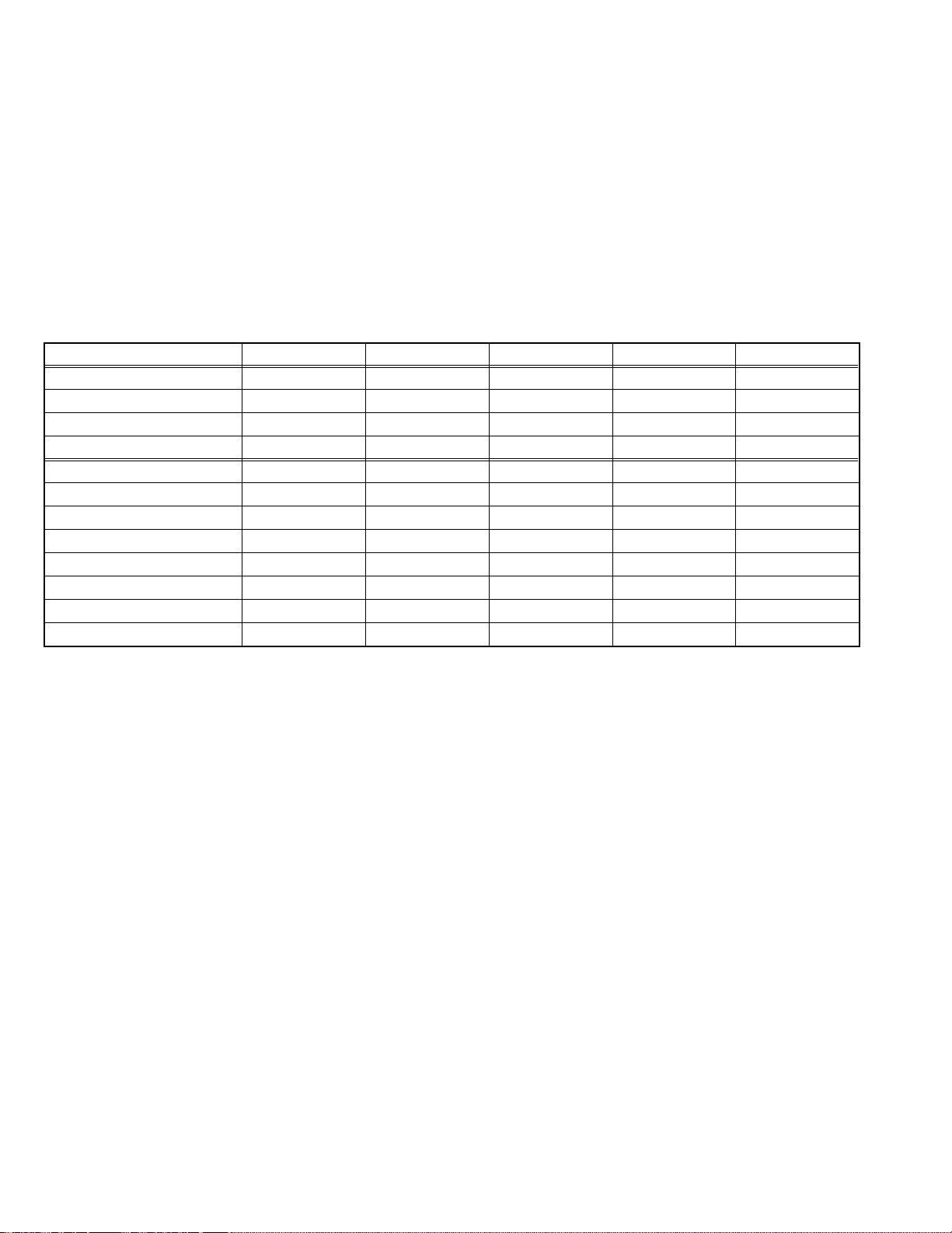
2.2 MAIN DIFFERENCE LIST
Item HV-29WH21 HV-29VH21/A HV-29WH21/E HV-29WH51/S HV-29WH71/G
TELETEXT YES YES YES NO YES
PIP NO NO NO YES YES
COLOUR AUTO NO NO NO YES NO
BLUE BACK MUTE NO NO NO YES NO
MAIN PWB ASSY SML-1501A-H2 SML-1511A-H2 SML-1510A-H2 SML-1508A-H2 SML-1503A-H2
POWER &DEF PWB ASSY SML-2501A-H2 SML-2501A-H2 SML-2503A-H2 SML-2501A-H2 SML-2501A-H2
MICOM /100Hz PWB ASSY SML0Z502A-H2 SML0Z502A-H2 SML0Z502A-H2 SML0Z501A-H2 SML0Z501A-H2
AV SW PWB ASSY SML0J501A-H2 SML0J501A-H2 SML0J501A-H2 SML0J503A-H2 SML0J503A-H2
PICTURE TUBE A68QCU770XV1K A68QCU770XV1S A68QCU770XV1K A68QCU770XV1K A68QCU770XV1K
FRONT CABI ASSY GG10189-010A-H GG10239-003A-H GG10189-010A-H GG10189-010A-H GG10189-010A-H
REAR COVER GG10192-005B-H GG10192-006B-H GG10192-005B-H GG10192-005B-H GG10192-005B-H
REMOTE CONTROL UNIT RM-C1351-1H RM-C1351-1H RM-C1351-1H RM-C1353-1H RM-C1350-2H
1-4 (No.52198)
Page 5
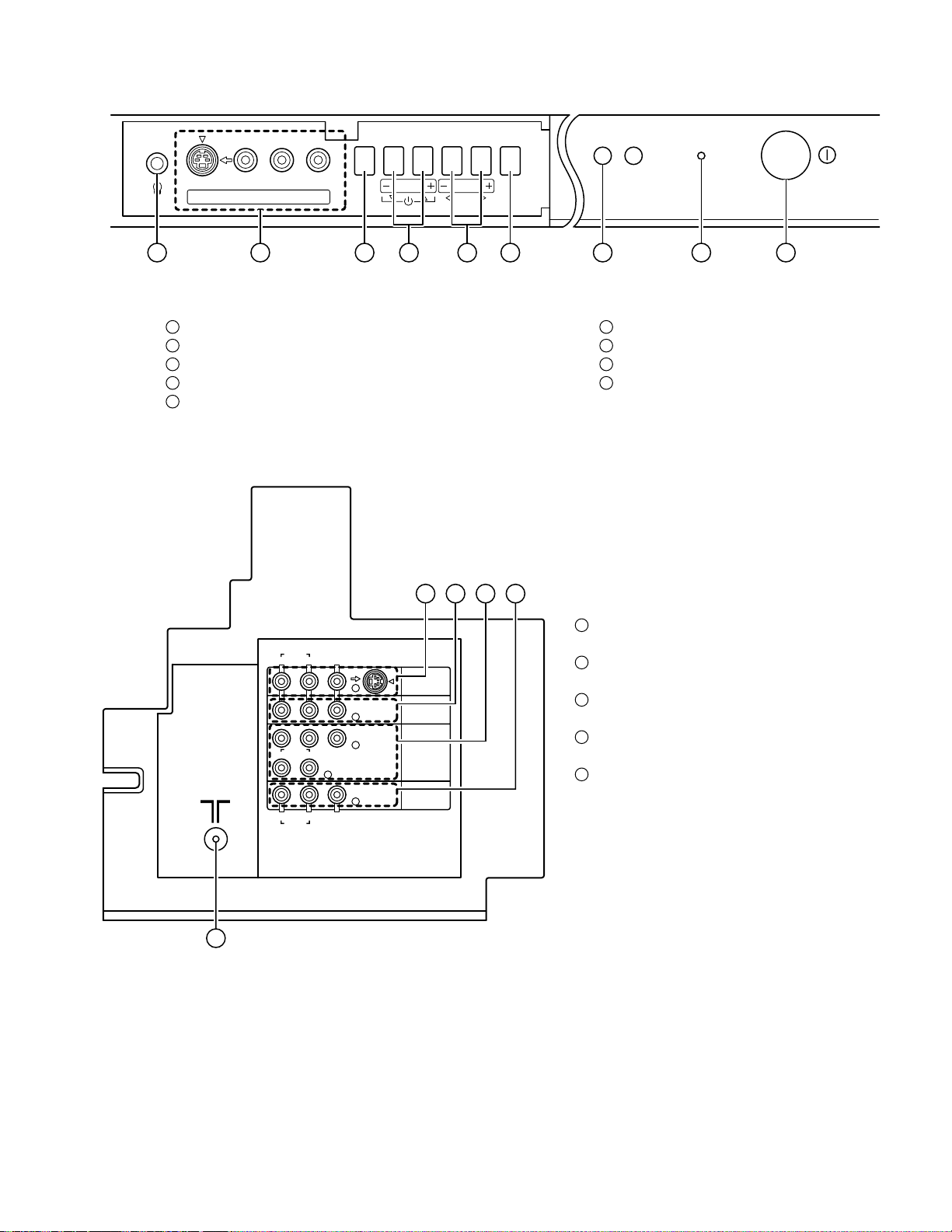
2.3 FUNCTIONS
FRONT TERMINAL & CONTROL
S
1 2 3 4 5 6 7 8 9
1
HEADPHONE jack
2
VIDEO-4 terminal (S-VIDEO / VIDEO / L/MONO / R)
3
MENU/OK button
4
CHANNEL -/+ (MENU UP/DOWN) button
5
VOLUME -/+ (MENU LEFT/RIGHT) button
REAR TERMINAL
OVER
V
IN (VIDEO-4)
L/MONO
R
MENU
OK
CHANNEL
VOLUME
TV/VIDEO
EXIT
6
TV / VIDEO / EXIT button
7
Remote Control sensor
8
POWER lamp
9
POWER button
POWER
1 2 3 4
1
VIDEO-1 (INPUT) terminal
R
R
R
AUDIO
L/MONO
C
R
AUDIO
L/MONO
AUDIO
VIDEO
B
L
VIDEO
S
OVER
Y/VIDEOC
VIDEO-1
VIDEO-2
VIDEO-3/
COMPONENT
OUTPUT
(S, VIDEO, L/MONO ,R)
2
VIDEO-2 (INPUT) terminal
( VIDEO, L/MONO ,R)
3
VIDEO-3 (INPUT) terminal
(Y/VIDEO, C
4
OUTPUT (VIDEO, AUDIO L/R) terminal
B,CR , L/MONO, R) /COMPONENT
(VIDEO, L, R)
5
AERIAL socket
5
(No.52198)1-5
Page 6
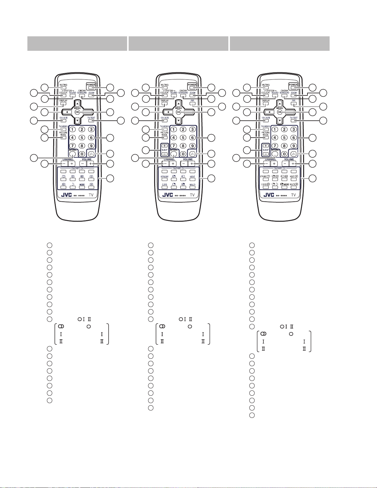
REMOTE CONTROL UNIT
RM-C1351
[HV-29WH21,HV-29WH21/E,HV-29VH21/A]
5
6
7
1
2
3
8
9
12
10
11
13
14
17
18
20
19
21
12
1616
RM-C1353
[HV-29WH51/S]
5
6
7
8
9
1
2
3
4
10
5
6
7
8
9
12
13
14
15
20
17
18
19
13
14
15
16
20
21
RM-C1350
[HV-29WH71/G]
1
2
3
4
10
11
17
18
19
21
1
POWER key
2
ZOOM key
3
CINEMA SURROUND key
5
MUTING key
6
COLOUR SYSTEM key
7
SOUND SYSTEM key
8
DISPLAY key
9
MENU (/&/) keys
10
MENU / OK key
11
TV/TEXT key
12
STEREO / key
:Stereo / :Mono
:Bilingual (sub )
:Bilingual (sub )
13
TV / VIDEO key
14
PICTURE MODE key
16
RETURN + key
17
CHANNEL keys
18
-/-- key
19
VOLUME +/- keys
20
CHANNEL +/- keys
21
FAVORITE CH keys
1
POWER key
2
ZOOM key
3
CINEMA SURROUND key
4
PIP key
5
MUTING key
6
COLOUR SYSTEM key
7
SOUND SYSTEM key
8
DISPLAY key
9
MENU (/&/) keys
10
MENU / OK key
12
STEREO / key
:Stereo / :Mono
:Bilingual (sub )
:Bilingual (sub )
13
TV / VIDEO key
14
PICTURE MODE key
15
SUB-P +/- key
16
RETURN + key
17
CHANNEL keys
18
-/-- key
19
VOLUME +/- keys
20
CHANNEL +/- keys
21
FAVORITE CH keys
1
POWER key
2
ZOOM key
3
CINEMA SURROUND key
4
PIP key
5
MUTING key
6
COLOUR SYSTEM key
7
SOUND SYSTEM key
8
DISPLAY key
9
MENU (/&/) keys
10
MENU / OK key
11
TV/TEXT key
12
STEREO / key
:Stereo / :Mono
:Bilingual (sub )
:Bilingual (sub )
13
TV / VIDEO key
14
PICTURE MODE key
15
SUB-P +/- key
16
RETURN + key
17
CHANNEL keys
18
-/-- key
19
VOLUME +/- keys
20
CHANNEL +/- keys
21
FAVORITE CH keys
1-6 (No.52198)
Page 7
SECTION 3
DISASSEMBLY
3.1 DISASSEMBLY PROCEDURE
3.1.1 REMOVING THE REAR COVER
(1) Unplug the power cord.
(2) Remove the 16 screws [A] as shown in the Fig. 1.
(3) Withdraw the REAR COVER toward you.
3.1.2 REMOVING THE AV TERMINAL BOARD
• Remove the REAR COVER.
(1) Remove the 5 screws [B] as shown in the Fig. 1.
(2) Withdraw the AV TERMINAL BOARD toward you.
3.1.3 REMOVING THE CHASSIS
• Remove the REAR COVER.
(1) Slightly raise the both sides of the CHASSIS by hand and
remove the 2 claws under the both sides of the CHASSIS
from the front cabinet.
(2) Withdraw the CHASSIS backward.
(If necessary, take off the wire clamp, connectors etc.)
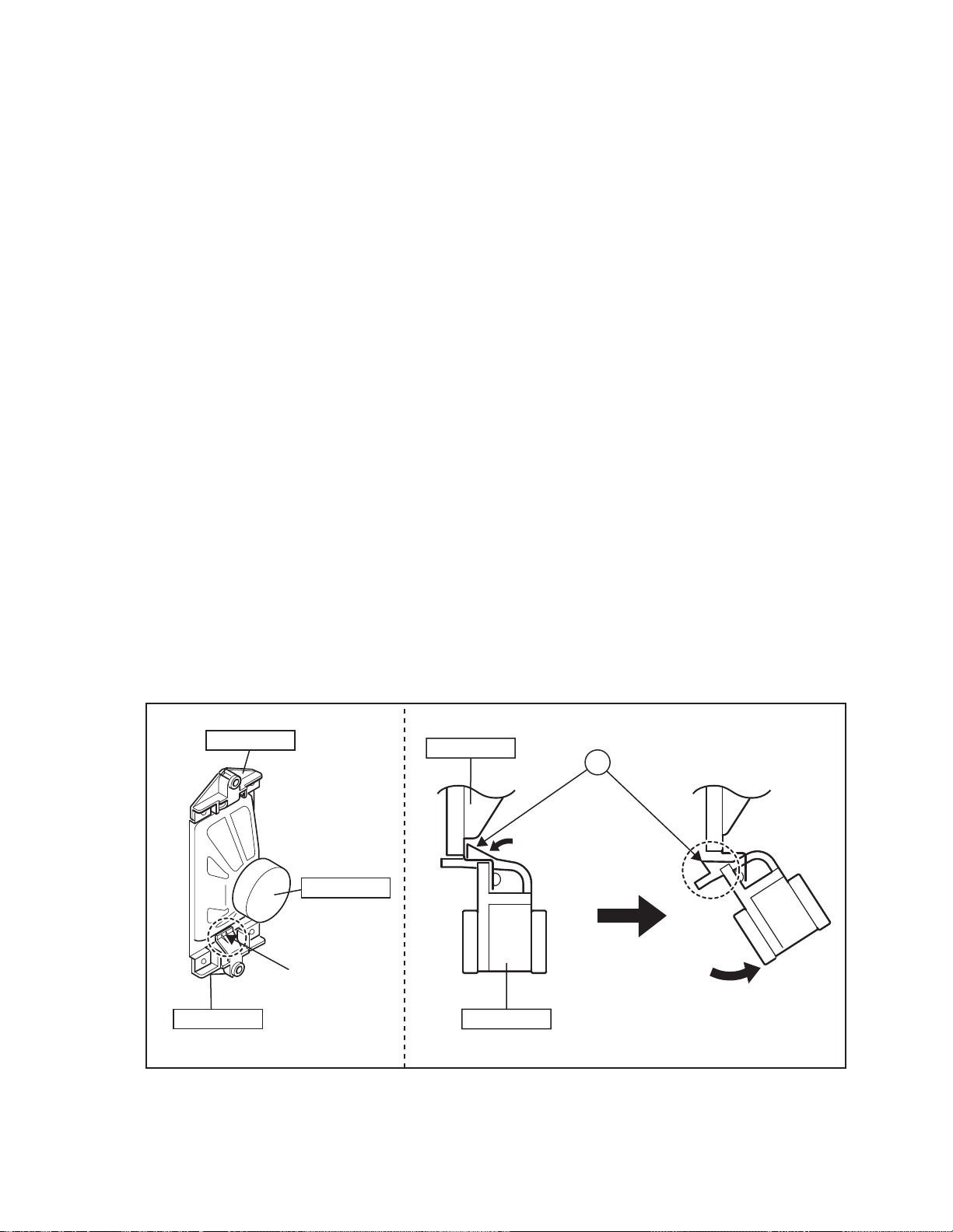
3.1.4 REMOVING THE SPEAKER
• Remove the REAR COVER.
(1) Remove the 2 screws [C], and remove the SP HOLDER as
shown in Fig. 1.
NOTE :
When removing the screws [C] of the SP HOLDER,
remove the lower side screw first, and then remove the
upper one.
(2) Remove the claw [D] push the SP HOL DER as shown in
Fig. 2.
(3) Follow the same steps when removing the other
SPEAKER.
3.1.5 CHECKING THE PW BOARD
• To check the back side of the PW Board.
(1) Pull out the CHASSIS. (Refer to REMOVING THE
CHASSIS).
(2) Erect the CHASSIS vertically so that you can easily check
the back side of the PW Board.
3.1.6 CAUTION
• When erecting the CHASSIS, be careful so that there will be
no contacting with other PW Board.
• Before turning on power, make sure that the wire connector is
properly connected.
• When conducting a check with power supplied, be sure to
confirm that the CRT EARTH WIRE (BRAIDED ASS'Y) is
connected to the CRT SOCKET PW board.
3.1.7 WIRE CLAMPING AND CABLE TYING
(1) Be sure to clamp the wire.
(2) Never remove the cable tie used for tying the wires togeth-
er.
Should it be inadvertently removed, be sue to tie the wires
with a new cable tie.
SP HOLDER
SPEAKER
CLAW
SP HOLDER SP HOLDER
SPEAKER
Fig.2
D
[SIDE VIEW]
(No.52198)1-7
Page 8
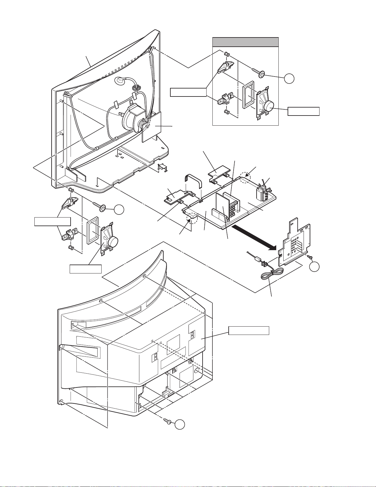
FRONT CABINET
See Fig. 2
C
(X2)
SP HOLDER
SPEAKER
CRT SOCKET
PWB
SP HOLDER
SPEAKER
FRONT CONTROL
PWB (1/2)
C
(X2)
CONTROL
BASE
FRONT CONTROL
PWB (2/2)
CLAW
MAIN PWB
MICOM / 100Hz
PWB
CLAW
FBT
POWER & DEF.
PWB
AV SW
PWB
B
(X5)
POWER CORD
1-8 (No.52198)
A
Fig.1
REAR COVER
(X16)
Page 9
3.2 MEMORY IC REPLACEMENT
3.2.1 MEMORY IC
This TV use memory IC.
In the memory IC, there are memorized data for correctly
operating the video and deflection circuits.
When replacing memory IC, be sure to use IC written with the
initial values of data.
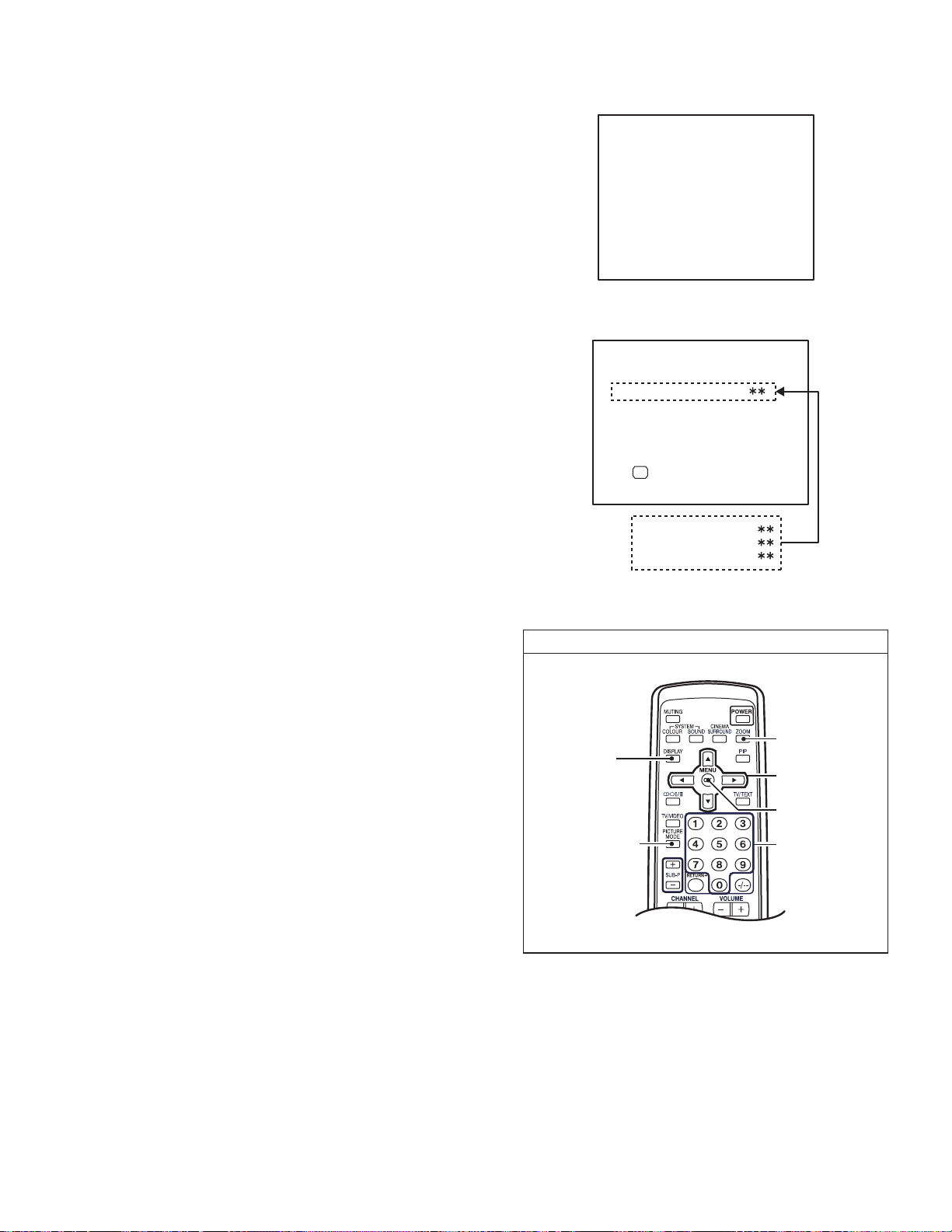
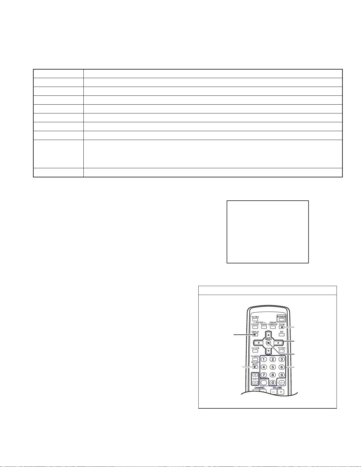
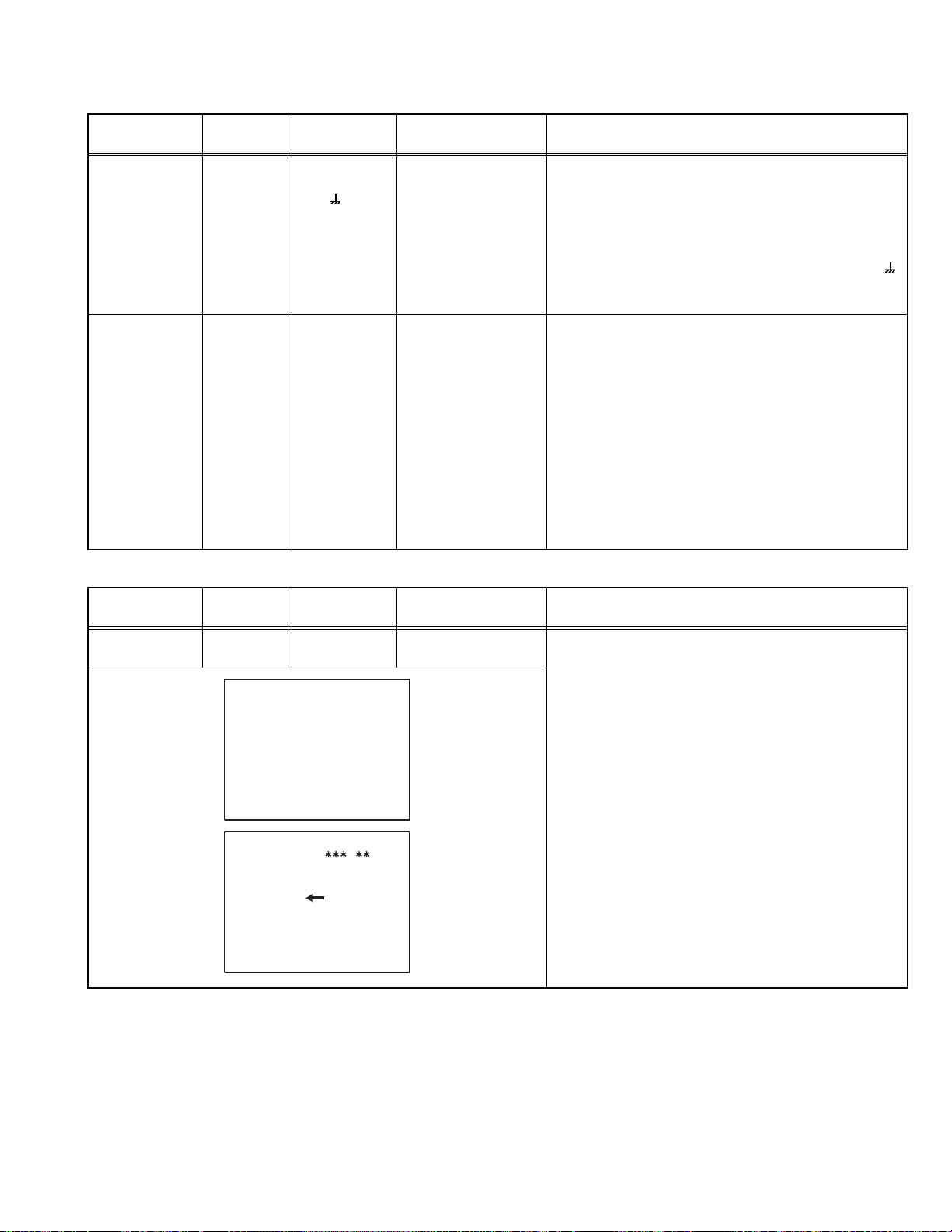
3.2.2 PROCEDURE FOR REPLACING MEMORY IC
(1) Power off
Switch the power off and disconnect the power cord from
the wall outlet.
(2) Replace the memory IC
Be sure to use a memory IC written with the initial data
values.
(3) Power on
Connect the power plug into the wall outlet and switch the
power on.
(4) Check and setting of SYSTEM CONSTANT SET
• It must not adjust without signal.
a) Press the [DISPLAY] key and the [PICTURE MODE]
key of the REMOTE CONTROL UNIT
simultaneously.
b) The SERVICE MENU screen of Fig. 1 will be
displayed.
c) While the SERVICE MENU is displayed, press the
[DISPLAY] key and [PICTURE MODE] key
simultaneously, and the SYSTEM CONSTANT SET
screen of Fig. 2 will be displayed.
d) Check the setting values of the SYSTEM
CONSTANT SETTING. If the value is different, select
the setting item with the [MENU /] key, and set
the correct value with the [MENU /] key.
e) Press the [OK] key to memorize the settin g value.
f) Press the [DISPLAY] key, and return to the normal
screen.
(5) Receive channels setting
Refer to the OPERATING INSTRUCTIONS and set the
receive channels (channels preset) as described.
(6) User settings
Check the user setting values and if setting value is
different, set the correct value. For setting, refer to the
OPERATING INSTRUCTIONS.
(7) Setting of SERVICE MENU
Verify the setting items of the SERVICE MENU, and reset
where necessary. For setting, refer to the SERVICE
ADJUSTMENTS.
1. IF
3. AUDIO
5. VSM PRESET
7.PIP
9. SHIPPING(OFF)
1-9 : SELECT DISP : EXIT
1. TEXT
DISPLAY key
PICTURE MODE
key
SERVICE MENU
2. V/C
4. DEF
6. STATUS
8. SURROUND
0. BUS FREE
Fig.1
SYSTEM CONTANT SET
OK
2. PIP
3. COLOUR AUTO
4. BLUE BACK MUTE
DISP : EXIT-/+ : STORE
Fig.2
SERVICE MENU
ZOOM
(ASPECT) key
MENU key
(/ & /)
OK key
Numbers keys
Fig.3
[RM-C1350]
(No.52198)1-9
Page 10
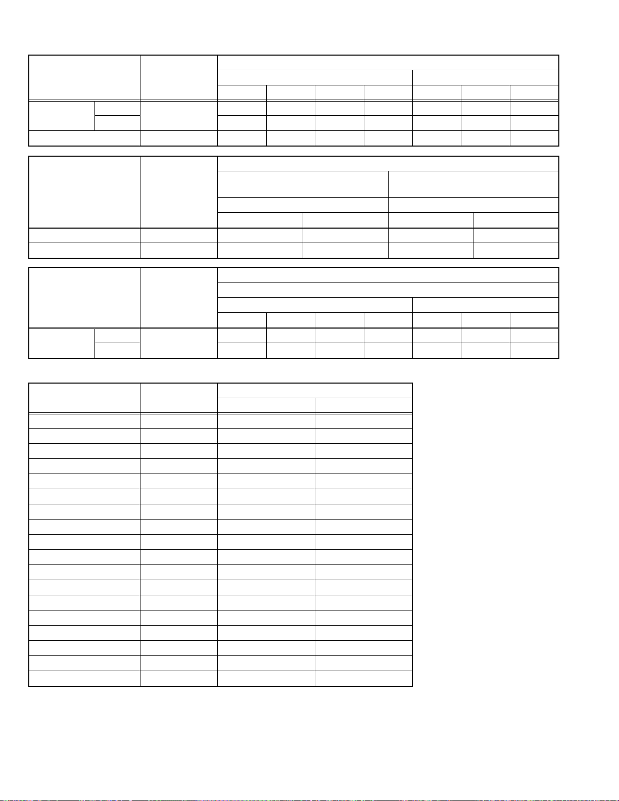
3.2.3 FACTORY SETTING VALUES
Setting item Setting value Setting item Setting value
MAIN POWER SW OFF SUB POWER SW ON
CHANNEL PR1 DISPLAY INDICATED
PRESET CHANNEL
Setting item Setting value Setting item Setting value
PICTURE SETTING SOUND
PICTURE MODE BRIGHT BASS Center
CONTRAST Center TREBLE Center
BRIGHT Center BALANCE Center
SHARP Center CINEMA SURROUND OFF
COLOUR Center AI VOLUME ON
WHITE BALANCE MID INSTALL
AI ECO SENSOR DISPLAY OFF LANGUAGE ENGLISH
PICTURE FEATURES EDIT PRESET CHANNEL ONLY
DIGITAL VNR AUTO OTHER : NON (SPACE)
Digi Pure AUTO AUTO PROGRAM GROUP-1 : HV-29WH21
PULL DOWN AUTO HV-29VH21/A
COLOUR SYSTEM TV : Depends on PR/CH
ZOOM REGULAR GROUP-4 : HV-29WH51/S
PICTURE TILT Center HV-29WH71/G
FAVORITE CH SETTING PRO1 : RED
VIDEO SETTING VIDEO STATAS : VIDEO1
See OPERATING INSTRUCTIONS.
MENU SETTING
EXT : AUTO
PRO2 : GREEN
PRO3 : YELLOW
PRO4 : BLUE
PICTIRE MODE : BRIGHT
DIGITAL VNR : AUTO
WHITE BALANCE : MID
Digi Pure : AUTO
PICTURE EFFRCT : OFF
PICTURE MODE : BRIGHT
DIGITAL VNR: AUTO
WHITE BALANCE : MID
Digi Pure : AUTO
PICTURE EFFECT : OFF
VOLUME 10
TELETEXT LANGUAGE GROUP-2 : Unused
GROUP-3 : HV-29WH21/E
GROUP-5 : Unused
FEATURES
SLEEP TIMER OFF
BLUE BACK ON
CHILD LOCK OFF (for all the channels)
CHANNEL GUARD ALL CH : OFF
AUTO SHUT OFF OFF
VIDEO-3 SETTING COMPONENT
PIP / TWIN OFF Only
SUB INPUT VIDEO1
HV-29WH51/S
HV-29WH71/G
1-10 (No.52198)
Page 11
3.2.4 SYSTEM CONSTANT SETTING
Setting item HV-29WH21 / HV-29VH21 HV-29WH51 HV-29WH71
1. TEXT YES NO YES
2. PIP NO YES YES
3. COLOUR AUTO NO YES NO
4. BLUE BACK MUTE NO YES NO
3.2.5 SERVICE MENU SETTING ITEMS
Setting item Setting value Setting item Setting value
1. IF 1. VCO 5. VSM PRESET BRIGHT
STANDARD
SOFT
2. V / C 1. RGB BLK
2. CUTOFF R
3. CUTOFF G
4. CUTOFF B
5. WDR R
6. WDR G
7. WDR B
8. BRIGHT
9. CONTRAST
10. COLOUR
11. HUE
12. SHARP
13. SC ADJ.
14. TOP BLK
15. BTM BLK
16. YUV BRIGHT
17. YUV CONT
18. YUV COLU
19. YUV COLV
20. YUV YDEL
21. YUV UVDEL
22. YCDELM
3. AUDIO 1. ERR LIMIT
2. A2 ID THR
3. SYSTEM
4. SUB BASS
5. SUB TREBLE
4. DEF 1. V-SHIFT
2. V-SIZE
3. H-CENT
4. H-SIZE
5. TRAPEZ
6. EW-PIN
7. COR-UP
8. COR-LO
9. COR-UP-S
10. COR-LO-S
11. HUE
12. BOW
13. V-S.CR
14. V-LIN
6. STATUS
(Do not adjust)
7. PIP
[HV-29WH51/S, HV-29WH71/G only]
8. SURROUND 1. CH CONFIG
COOL
WARM
NORMAL
1. CONT
2. BRIGHT
3. SHARP
4. COLOUR
5. TINT
6. WDR R
7. WDR G
8. WDR B (Do not adjust)
1. SOFT
1. HUE
2. SCADJ
3. PIP HOR POS
4. PIP VER POS
5. YCDELS
2. MATRIX
3. REPRODUCT
4. CENTER MODE
5. SPATIAL EFF
6. VIRTUAL EFF
7. BASS EFFECT
8. HARM
9. HPF
10. LPF
11. AMP LIMIT
12. LEVEL ADJ
13. SWC
14. SW HPF
15. VOLUME
16. HYPER EFF
17. EFFECT MOD
18. HP GAIN
(No.52198)1-11
Page 12
3.3 REPLACEMENT OF CHIP COMPONENT
3.3.1 CAUTIONS
(1) Avoid heating for more than 3 seconds.
(2) Do not rub the electrodes and the resist parts of the pattern.
(3) When removing a chip part, melt the solder adequately.
(4) Do not reuse a chip part after removing it.
3.3.2 SOLDERING IRON
(1) Use a high insulation soldering iron with a thin pointed end of it.
(2) A 30w soldering iron is recommended for ea sily removing parts.
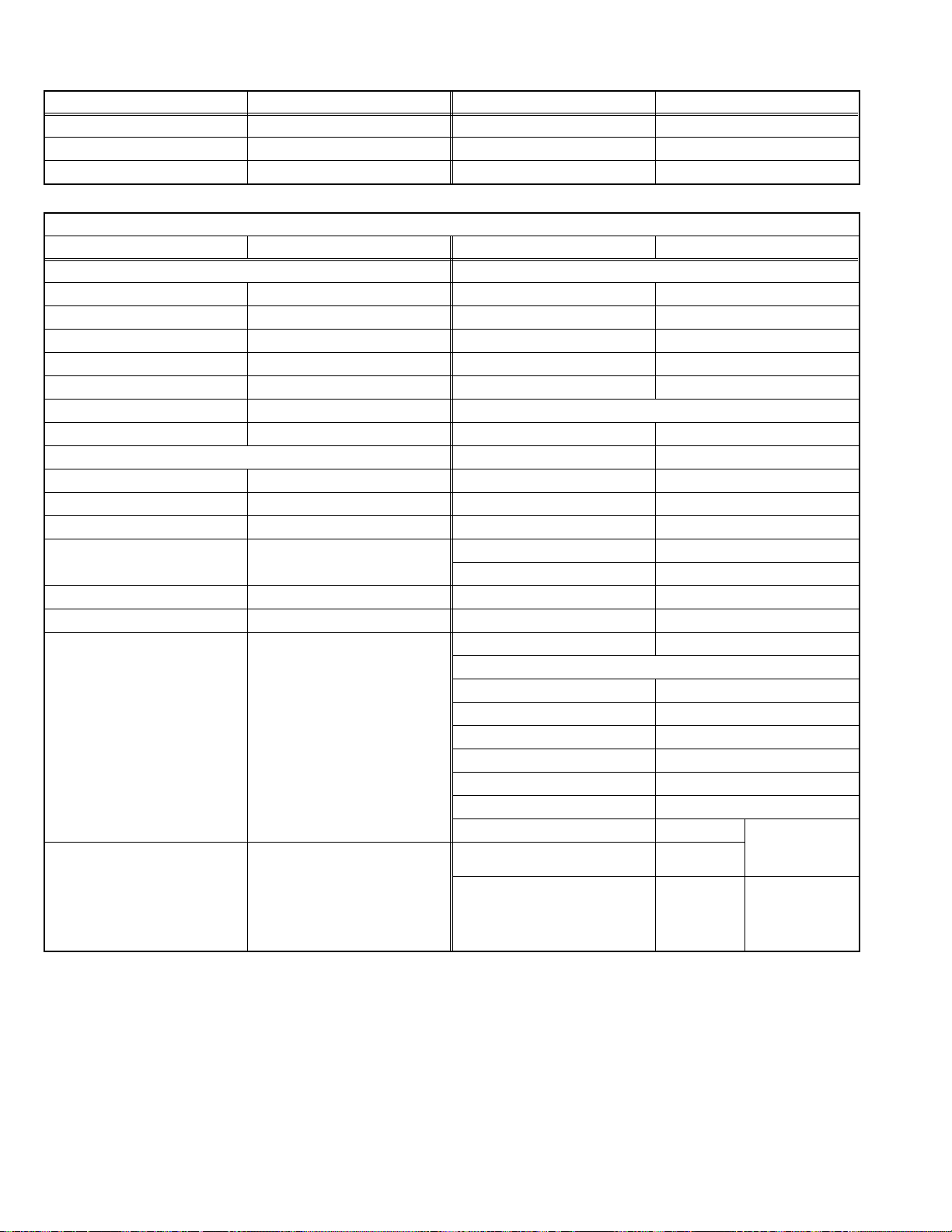
3.3.3 REPLACEMENT STEPS
1. How to remove Chip parts
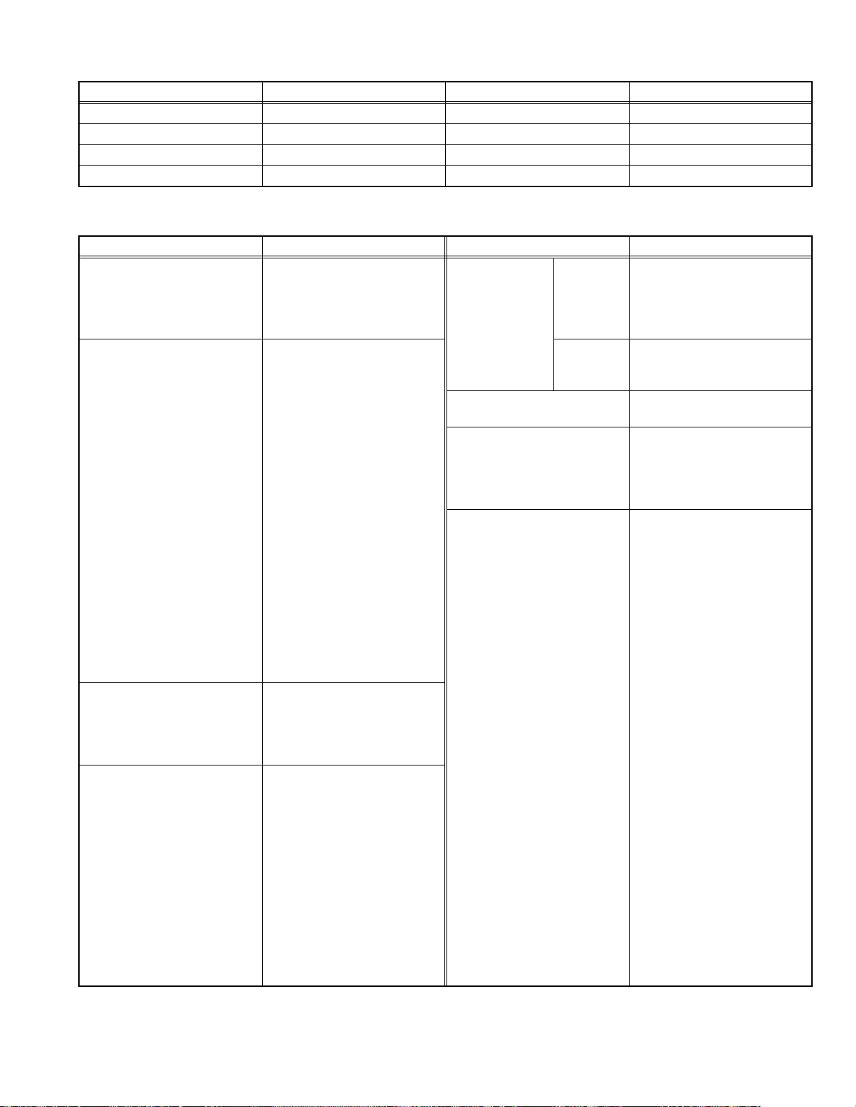
2. How to install Chip parts
[Resistors, capacitors, etc.]
(1) As shown in the figure, push the part with tweezers and
alternately melt the solder at each end.
(2) Shift with the tweezers and remove the chip part.
[Transistors, diodes, variable resistors, etc.]
(1) Apply extra solder to each lead.
SOLDER
SOLDER
[Resistors, capacitors, etc.]
(1) Apply solder to the pattern as indicated in the figure.
(2) Grasp the chip part with tweezers and place it on the
solder. Then heat and melt the solder at both ends of the
chip part.
[Transistors, diodes, variable resistors, etc.]
(1) Apply solder to the pattern as indicated in the figure.
(2) Grasp the chip part with tweezers and place it on the
solder.
(3) First solder lead A as indicated in the figure.
(2) As shown in the figure, push the part with tweezers and
alternately melt the solder at each lead. Shift and remove
the chip part.
NOTE :
After removing the part, remove remaining solder from the
pattern.
1-12 (No.52198)
A
B
C
(4) Then solder leads B and C.
A
B
C
Page 13
SECTION 4
ADJUSTMENT
4.1 ADJUSTMENT PREPARATION
(1) There are 2 ways of adjusting this TV : One is with the REMOTE CONTROL UNIT an d the other is the conventional method
using adjustment parts and components.
(2) The adjustment using the REMOTE CONTROL UNIT is made on the basis of the initial setting values. The setting values which
adjust the screen to the optimum condition can be different from the initial setting values.
(3) Make sure that connection is correctly made AC to AC power source.
(4) Turn on the power of the TV and measuring instruments for warning up for at least 30 minutes before starting adjustme nts.
(5) If the receive or input signal is not specified, use the most appropriate signal for adjustment.
(6) Never touch the parts (such as variable resistors, transformers and condensers) not shown in the adjustment items of this service
adjustment.
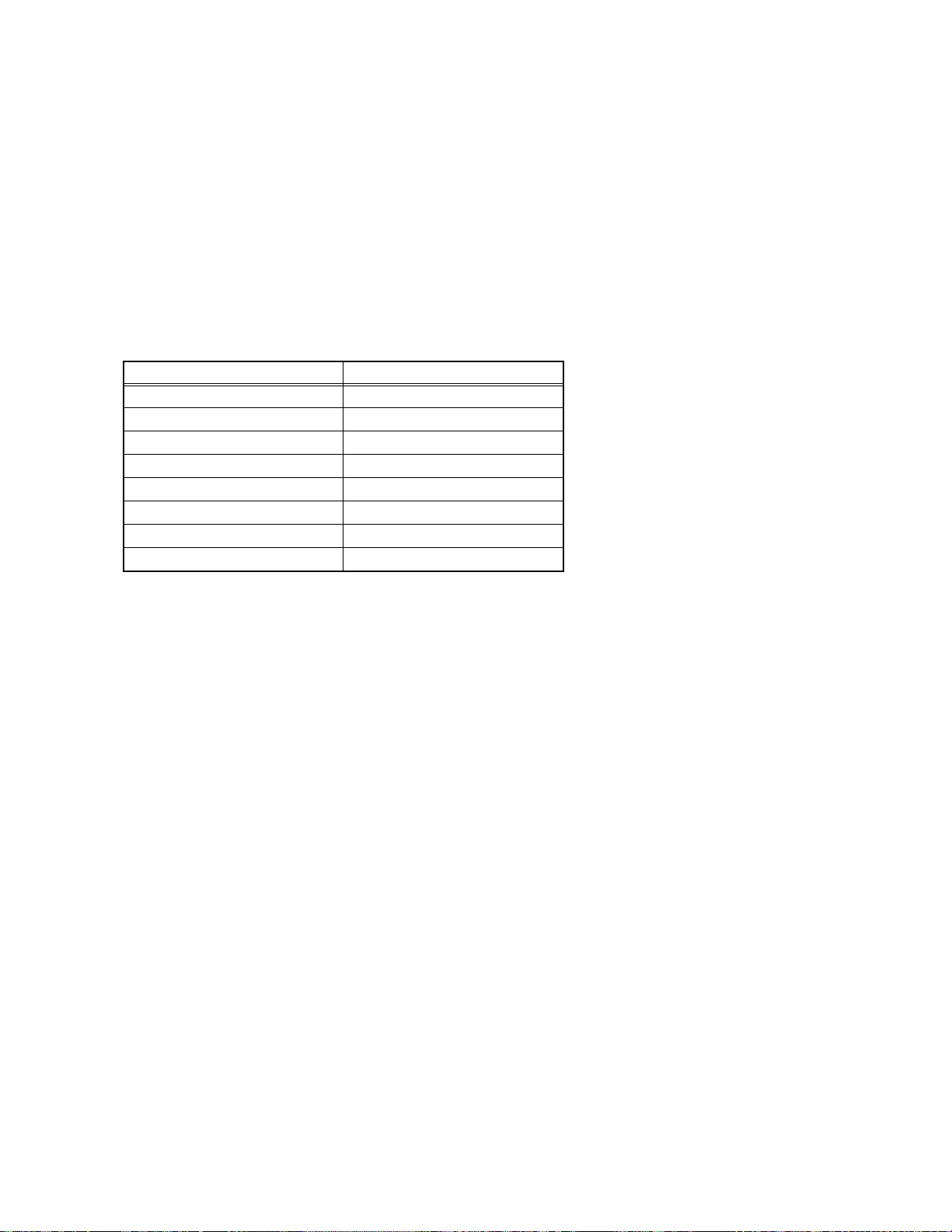
(7) Preparation for ad justment.
Unless otherwise specified in the adjustment items, preset the following functions with the REMOTE CONTROL UNIT.
Item Preset value
PICTURE MODE (VSM) STANDARD
WHITE BALANCE MID
DIGITAL VNR AUTO
Digi Pure AUTO
BASS / TREBLE / BALANCE Center
CINEMA SURROUND OFF
ZOOM REGULAR
SLEEP TIMER OFF
4.2 MEASURING INSTRUMENT AND FIXTURES
(1) DC voltmeter (or digital voltmeter)
(2) HV voltmeter
(3) Oscilloscope
(4) Signal generator (Pattern generator : PAL / SECAM / NTSC)
(5) Remote control unit
4.3 ADJUSTMENT ITEMS
CHECK ITEMS
• B1 POWER SUPPLY check
• HIGH VOLTAGE check
TUNER / IF CURCUIT
• IF VCO check
FOCUS
• FOCUS adjustment
VSM PRESET SETTING
• VSM PRESET
VIDEO CIRCUIT
• WHITE BALANCE adjustment
• SUB BRIGHT adjustment
• SUB CONTRAST adjustment
• SUB COLOUR-1 adjustment
• SUB COLOUR-2 adjustment
• SUB HUE-1 adjustment
• SUB HUE-2 adjustment
• COLOUR DECODER VCO adjustment
DEFLECTION CIRCUIT
• V. POSITION adjustment
• V. SIZE adjustment
• H. POSITION adjustment
• H. SIZE adjustment
• SIDE-PIN adjustment
• TRAPEZIUM adjustment
• UPPER / LOWER CORNER PIN adjustment
• PARALLEL(TILT) adjustment
• BOW adjustment
• V. S-SHAPE CORRECTION & LINEARITY adjustment
AUDIO CIRCUIT
(No.52198)1-13
Page 14
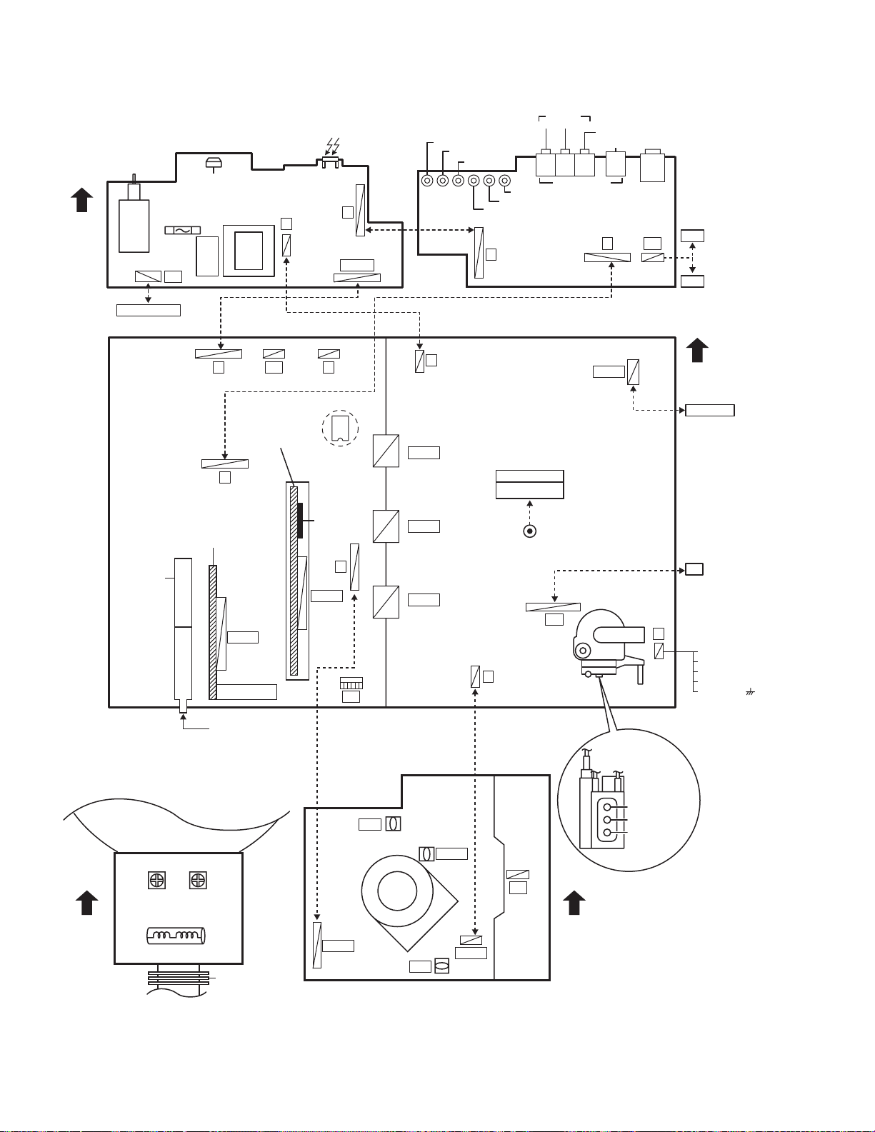
4.4 ADJUSTMENT LOCATION
FRONT CONTROL PWB(1/2) FRONT CONTROL PWB(2/2)
FRONT
POWER CORD
POWER
F901
C901
PW
W
LF901
MAIN PWB
IC101
J
CN00B
TV/VIDEO EXIT
VOL +
VOL -
MENU / OK
CH -
CH +
J
POWER &DEF PWB
AUDIO
R L/MONO
R4 L4 V4
IN (VIDEO-4)
VIDEO
S-VIDEO
S IN
F
HEAD
POHONE
SP
SP-R
SP-L
FRONT
TUNER
B
MICOM / 100Hz
PWB
F
AV SW PWB
CN001
ANT- IN
CN003
CN004
CN005
W
CRT
BRAIDED WIRE
HV
G
DEG
DEG COIL
DY
X
1
1pin:B1(TP-91)
5
2pin:NC
3pin:X-RAY
4pin:X-RAY
5pin:GND( )
RT
A
MEMORY IC
IC701
IC001
MICON
R
CN002
C1
CRT SOCKET PWB
CN00R
TP-E
TP-47B
VM
CN00G
TP-Y
CRT
FRONT TOP
YHC
(VR2)
XV COIL
YV
(VR1)
PC MAGNET
(SOLDER SIDE)
1-14 (No.52198)
H
FOCUS 2 VR
FOCUS 1 VR
V
SCREEN VR
Page 15
4.5 BASIC OPERATION OF SERVICE MENU
4.5.1 TOOL OF SERVICE MENU OPERATION
Operate the SERVICE MENU with the REMOTE CONTROL UNIT.
4.5.2 SERVICE MENU ITEMS
With the SERVICE MENU, various adjustments can be made, and they are broadly classified in the following items of settings.
1.IF This mode adjusts the setting values of the IF circuit.
2.V/C This mode adjusts the setting values of the VIDEO circuit.
3.AUDIO This mode adjusts the setting values of the multiplicity AUDIO circuit.
4.DEF This mode adjusts the setting values of the DEFLECTION circuit for each aspect mode given below.
5.VSM PRESET This mode adjusts the initial setting values of BRIGHT, STANDARD and SOFT. (VSM : Video Status Memory)
6.STATUS It is no requirement to adjustment. [Do not adjust]
7.PIP This mode adjusts the setting values of the PIP circuit. [HV-29WH51/S HV-29WH71/G only]
8.SURROUND This mode adjusts the setting values of the SURROUND circuit.
9.SHIPPING (OFF) This mode adjusts the setting values of the channel presettings.
If you turn the SHIPPING position set ON.
This setting becomes channel presetting automatically.
Also you turn the TV power off, this setting become OFF position automatically.
0.BUS FREE It is not requirement to adjustment.
4.5.3 BASIC OPERATION OF SERVICE MENU
1. HOW TO ENTER THE SERVICE MENU
Press the [PICTURE MODE] key and the [DISPLAY] key of the
REMOTE CONTROL UNIT simultaneously, and the SERVICE
MENU screen of Fig. 1 will be displayed.
2. SELECTION OF SUB MENU SCREEN
Press one of [1] ~ [0] keys of the REMOTE CONTROL UNIT
and select the SERVICE MENU SCREEN (See Fig. 3), form
1. IF
3. AUDIO
5. VSM PRESET
7.PIP
9. SHIPPING(OFF)
1-9 : SELECT DISP : EXIT
SERVICE MENU
2. V/C
4. DEF
6. STATUS
8. SURROUND
0. BUS FREE
the SERVICE MENU.
Fig.1
1. IF
2. V/C
3. AUDIO
4. DEF
SERVICE MENU
5. VSM PRESET
6. STATUS [Do not adjust]
7. PIP [HV-29WH51/S, HV-29WH71/G only]
8. SURROUND
9. SHIPPING(OFF)
0. BUS FREE
DISPLAY key
ZOOM
(ASPECT) key
MENU key
(/ & /)
OK key
PICTURE MODE
key
Numbers keys
[RM-C1350]
Fig.2
(No.52198)1-15
Page 16

3. SETTING METHOD
1.IF
[1. VCO] : It must not adjust without signal
(1) [1] key
Select 1.IF.
(2) [1] key
Select 1.VCO(CW).
Check the arrow position between the ABOVE REF. and BELOW REF.
(3) [DISPLAY] key
Return to the SERVICE MENU screen.
2.V/C, 3.AUDIO, 4.DEF, 5.VSM PRESET, 7.PIP AND 8.SURROUND.
(1) [2], [3], [4], [5], [7], [8] key
Select one from 2.V/C, 3.AUDIO, 4.DEF, 5.VSM PRESET, 7.PIP, 8.SURROUND.
(2) [MENU /] key
Select setting items.
(3) [MENU /] key
Set (adjust) the setting values of the setting items.
(4) MENU [OK] key
Memorize the setting value.
(Before storing the setting values in memory, do not press the CH, TV, POWER ON / OFF key. if you do, the values will not
be stored in memory.)
(5) [DISPLAY] key
Return to the SERVICE MENU screen.
6.STATUS, 9. SHIPPING(OFF) AND 0. BUS FREE.
It is not requirement to adjustment.
4. RELEASE OF SERVICE MENU
After completing the setting, return to the SERVICE MENU, then again press the [DISPLAY] key.
1-16 (No.52198)
Page 17
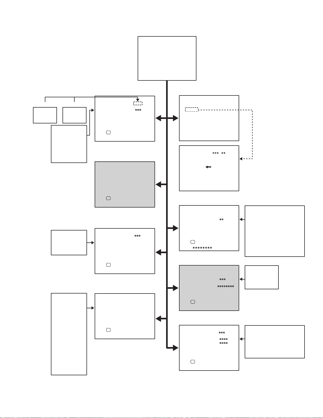
4.5.4 SERVICE MENU FLOW CHART
SERVICE MENU
SERVICE MENU
1. IF
3. AUDIO
5. VSM PRESET
7.PIP
9. SHIPPING(OFF)
1-9 : SELECT DISP : EXIT
2. V/C
4. DEF
6. STATUS
8. SURROUND
0. BUS FREE
COLOUR TEMP
COOL
WARM
NORMAL
1. CONT
2. BRIGHT
3. SHARP
4. COLOUR
5. TINT
6. WDR R
7. WDR G
8. WDR B
1. HUE
2. SC ADJ
3. PIP HOR POS
4. PIP VER POS
5. YCDELS
1. CH CONFIG
2. MATRIX
3. REPRODUCT
4. CENTER MODE
5. SPATIAL EFF
6. VIRTUAL EFF
7. BASS EFFECT
8. HARM
9. HPF
10. LPF
11. AMP LIMIT
12. LEVEL ADJ
13. SWC
14. SW HPF
15. VOLUME
16. HYPER EFF
17. EFFECT MOD
18. HP GAIN
PICTURE MODE
BRIGHT
STANDARD
SOFT
5. VSM PRESET
VSM PRESET STD
1. CONT
OK
DISP : EXIT-/+ : STORE
6. STATUS [Do not adjust]
STATUS
1. SOFT
OK
[HV-29WH51/S HV-29WH71/G only]
PIP
1. HUE
OK
DISP : EXIT-/+ : STORE
7. PIP
DISP : EXIT-/+ : STORE
8. SURROUND
SURROUND SOUND SYSTEM
1. CH CONFIG
OK
DISP : EXIT-/+ : STORE
Fig.3
1. IF (CW)
IF SERVICE MENU
1. VCO
DISP : EXIT1-2 : SELECT
VCO(CW)
TOO HIGH
ABOVE REF
JUST REF
BELOW REF
TOO LOW
,
DISP : EXIT
MHz
2. V/C
V/C PAL
1. RGB_BLK
OK
DISP : EXIT-/+ : STORE
3. AUDIO [Do not adjust]
AUDIO
1. ERR LIMIT
EEROR_RATE=
OK
DISP : EXIT-/+ : STORE
4. DEF
DEF REGULAR Hz
1. V-SHIFT
OK
( )
DISP : EXIT-/+ : STORE
1. RGB BLK
2. CUTOFF R
3. CUTOFF G
4. CUTOFF B
5. WDR R
6. WDR G
7. WDR B
8. BRIGHT
9. CONTRAST
10. COLOUR
11. HUE
1. ERR LIMIT
2. A2 ID THR
3. SYSTEM
4. SUB BASS
5. SUB TREBLE
1. V-SHIFT
2. V-SIZE
3. H-CENT
4. H-SIZE
5. TRAPEZ
6. EW-PIN
7. COR-UP
12. SHARP
13. SC ADJ.
14. TOP BLK
15. BTM BLK
16. YUV BRIGHT
17. YUV CONT
18. YUV COLU
19. YUV COLV
20. YUV YDEL
21. YUV UVDEL
22. YCDELM
8. COR-LO
9. COR-UP-S
10. COR-LO-S
11. HUE
12. BOW
13. V-S.CR
14. V-LIN
(No.52198)1-17
Page 18
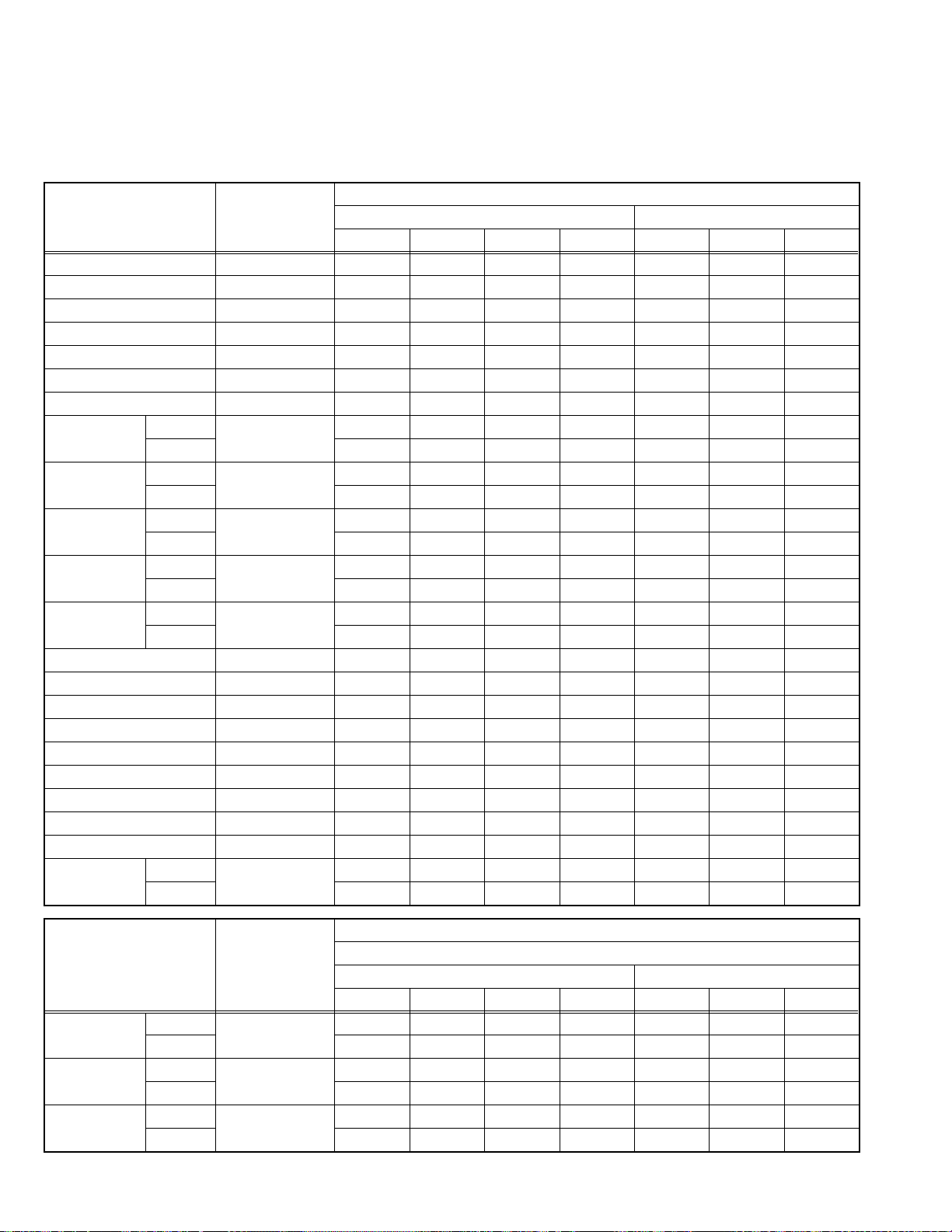
4.6 INITIAL SETTING VALUE OF SERVICE MENU
(1) Adjustment of the SERVICE MENU is made on the basis of the initial setting value s:however, the new setting values which set
the screen in its optimum condition may differ from the initial setting value.
(2) Do not change the initial setting values of the setting items not listed in "ADJUSTMENT PROCEDURE".
(3) "---" is impossible to adjust.
[2. V/C]
Initial setting value
Setting item Variable range
1. RGB BLK --- --- --- --- --- --- --- ---
2. CUTOFF R 0000~0255 150 150 150 150 5 5 0
3. CUTOFF G 0000~0255 150 150 150 150 -8 -8 0
4. CUTOFF B 0000~0255 150 150 150 150 0 0 0
5. WDR R 0000~0255 150 150 150 150 0 0 0
6. WDR G 0000~0255 150 150 150 150 0 0 0
7. WDR B 0000~0255 150 150 150 150 0 0 0
8. BRIGHT RF -128~0127 -25 -25 -25 -25 --- --- --VIDEO +6 +6 +6 +6 +2 +2 -4
9. CONTRAST RF 0000~0063 50 50 50 50 --- --- --VIDEO +15 +15 +15 +15 --- --- ---
10. COLOUR RF 0000~0063 36 55 25 5 --- --- --VIDEO -7 -3 -3 0 -14 -5 +5
11. HUE RF -064~0063 --- --- 4 0 --- --- --VIDEO --- --- 0 0 --- --- ---
12. SHARP RF -015~0015 -3 -3 -3 -3 0 0 0
VIDEO 0 0 0 0 0 0 0
13. SC ADJ 0000~0063 18 18 18 18 --- --- ---
14. TOP BLK 0000~0255 35 35 46 46 35 46 46
15. BTM BLK -127~0511 -15 -15 -37 -37 -15 -37 -37
16. YUV BRIGHT -064~0063 --- --- --- --- -4 -4 -4
17. YUV CONT 0000~0063 --- --- --- --- 55 55 55
18. YUV COLU 0000~0063 --- --- --- --- 57 60 10
19. YUV COLV 0000~0063 --- --- --- --- 6 0 55 0
20. YUV YDEL 0000~0127 --- --- --- --- 50 50 35
21. YUV UVDEL 0000~0127 --- --- --- --- 49 49 35
22. TCDELM RF 0000~0127 2 0 0 0 --- --- --VIDEO 0 0 0 0 --- --- ---
RF / Composite Video / S-Video Component video
PAL SECAM NTSC 3.58 NTSC 4.43 50Hz-i 60Hz-i 60Hz-p
Initial setting value
Setting item Variable range
8. BRIGHT RF -128~0127 0 0 0 0 0 0 0
VIEDO 0 0 0 0 0 0 0
9. CONTRAST RF 0000~0063 -7 -7 -7 -7 --- --- --VIDEO -7 -7 -7 -7 --- --- ---
10. COLOUR RF 0000~0063 0 0 0 0 --- --- --VIDEO 0 0 0 0 0 0 0
1-18 (No.52198)
RF/ Composite Video / S-Video Component video
PAL SECAM NTSC 3.58 NTSC 4.43 50Hz-i 60Hz-i 60Hz-p
Compress (16:9)
Page 19
[3. AUDIO]
Setting item Variable range Ini tial setting value
1. ERR LIMIT 0000~00FF 0010
2. A2 ID THR 0000~00FF 0019
3. SYSTEM B/G→I→D/K→M ---
4. SUB BASS -003~0003 0001
5. SUB TREBLE -003~0003 0001
[4. DEFLECTION]
Initial setting value
Setting item Variable range
1. V-SHIFT -32~0031+3-20000
2. V-SIZE -064~0063 -11 -1 0 0 -30 0
3. H-CENT -128 ~0127 -16 0 -2 0 0 0
4. H-SIZE -128~0127+7-10000
5. TRAPEZ -063~0064 -2 0 0 0 +1 0
6. EW-PIN -128~0127-17-10000
7. COR-UP -064~0064+1+160000
8. COR-LO -064~0064+1+60000
9. COR-UP-S -064 ~0064 +1 -8 0 0 0 +5
10. COR-LO-S -064~0064+100000
11. HUE -128~0127000000
12. BOW -128~0127000000
13. V-S.CR -064~0063+16+50000
14. V-LIN -064~0063-100000
REGULAR ZOOM 16:9
50Hz-i 60Hz-p 50Hz-i 60Hz-p 50Hz-i 60Hz-p
[5. VSM PRESET] [Do not adjust : All fixed]
Setting item Variable range
1. CONT -16~16 16 -2 0 --- --- ---
2. BRIGHT -16~16 -2 -2 0 --- --- ---
3. SHARP -16~16 0 -10 0 --- --- ---
4. COLOUR -16~16 0 -2 0 --- --- ---
5. TINT -16~16 0 0 0 --- --- ---
6. WDR R -16~16 --- --- --- -12 22 0
7. WDR G -16~16 --- --- --- -11 2 0
8. WDR B -16~16 --- --- --- 0 0 0
BRIGHT SOFT STANDARD COOL WARM NORMAL
Initial setting value
(No.52198)1-19
Page 20
[7. PIP] (HV-29WH51/S, HV-29WH71/G only)
Initial setting value
Setting item Variable range
1. HUE RF -128~0126 --- --- 0 -1 --- --- --VIDEO --- --- -1 -1 --- --- ---
2. SC ADJ 0000~0063 17 17 17 17 17 17 17
Setting item
(Position display)
3. PIP HOR POS 0000~2047 222 585 217 585
4. PIP VER POS 0000~1023 47 198 32 159
Setting item Variable range
5. YCDELS RF -016~0015 0 0 0 0 --- --- --VIDEO 0 0 0 0 --- --- ---
Variable range
RF / Composite Video / S-Video Component video
PAL SECAM NTSC 3.58 NTSC 4.43 50Hz-i 60Hz-i 60Hz-p
Initial setting value
PAL / SECAM / Component 50Hz-i
PIP position PIP position
LeftRightLeftRight
Initial setting value
Regular
RF / Composite Video / S-Video Component video
PAL SECAM NTSC 3.58 NTSC 4.43 50Hz-i 60Hz-i 60Hz-p
NTSC3.58 / NTSC4.43 /
Component 60Hz-i / 60Hz-p
[8. SURROND]
Setting item Variable range
1. CH CONFIG 0000~0001 1 1
2. MATRIX 0000~0127 16 16
3. REPRODUCT 0000~0015 6 6
4. CENTER MODE 0000~0015 3 3
5. SPATIAL EFF 0000~0127 40 50
6. VIRTUAL EFF 0000~0127 35 47
7. BASS EFFECT 0000~0127 46 52
8. HARM 0000~0127 0 0
9. HPF 0002~0030 8 8
10. LPF 0005~0030 18 15
11. AMP LIMIT -032~0000 -10 -15
12. LEVEL ADJ -128~0012 0 0
13. SWC 0005~0040 28 28
14. SW HPF 0000~0002 2 2
15. VOLUME 0000~0003 3 3
16. HYPER EFF 0000~0127 63 63
17. EFFECT MOD 0000~0002 0 0
18. HP GAIN 0000~0008 8 8
Initial setting value
LOW HIGH
1-20 (No.52198)
Page 21
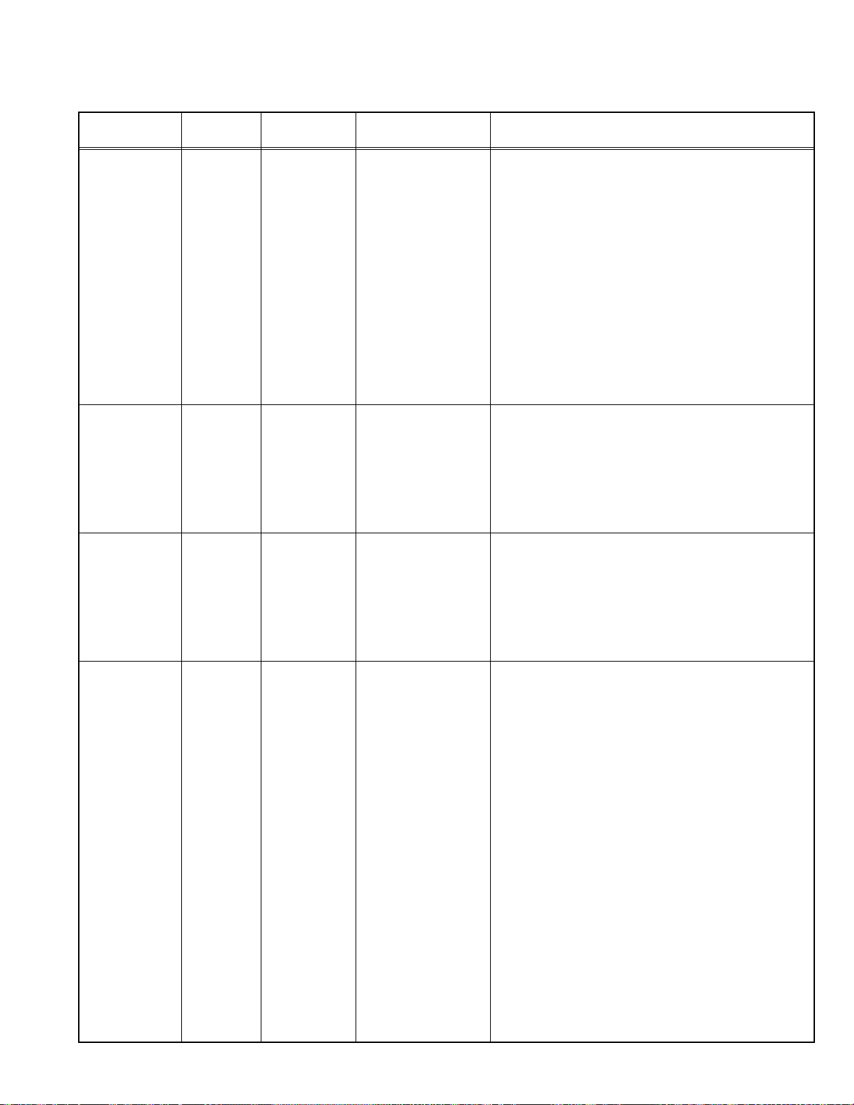
4.7 ADJUSTMENT PROCEDURE
4.7.1 CHECK ITEM
Item
B1 POWER
SUPPLY
check
Measuring
instrument
DC voltmeter
Remote
control unit
X connector
TP-91(B1)
TP-E( )
[POWER DEF
PWB]
HIGH VOLTAGE
HV voltmeter
CRT anode
check
Remote
Chassis GND
control unit
Test point Adjustment part Description
[2.V/C]
1.RGB BLK
(1) Receive a any broadcast.
(2) Press the [ZOOM] key and select the FULL mode.
(3) Select 2.V/C.
(4) Select < 1.RGB BLK >.
(5) Press the [MENU] key to find the cut off screen
(Black screen).
(6) Connect a DC voltmeter to TP-91(B1) and TP-E( ).
(7) Make sure that the voltage is DC139.9 ±2.0V.
(8) Press the [MENU] key to return to service menu.
[2.V/C]
1.RGB BLK
(1) Receive a any broadcast.
(2) Press the [ZOOM] key and select the FULL mode.
(3) Select 2.V/C.
(4) Select < 1. RGB BLK >.
(5) Press the [MENU] key to find the cut off screen
(Black screen).
(6) Connect a HV voltmeter to CRT anode and chassis
GND.
(7) Make sure that the voltage is DC31.5kV(+1kV,-
1.5kV).
(8) Press the [MENU] key to return to service menu.
NOTE:
• Remove the probe before removing the earth clip.
4.7.2 TUNER / IF CIRCUIT
Item
IF VCO
check
Measuring
instrument
Remote
control unit
1. VCO
TOO HIGH
ABOVE REF
JUST REF
BELOW REF
TOO LOW
Test point Adjustment part Description
IF SERVICE MENU
DISP : EXIT1-2 : SELECT
VCO(CW) , MHz
DISP : EXIT
[1.IF]
1.VCO
• Under normal conditions, no adjustment is required.
• Confirmation adjustment.
(1) Select 1.IF.
(2) Select < 1.VCO >
(3) Receive any broadcast.
(4) Check the arrow (←) position between the ABOVE
REF. and BELOW REF.
(5) Press the [OK] key and receiver any broadcast with
PIP button.
(No.52198)1-21
Page 22

4.7.3 FOCUS
Item
Measuring
instrument
FOCUS Signal
generator
HVT
FOCUS 2 VR
FOCUS 1 VR
SCREEN VR
Test point Adjustment part Description
FOCUS1 VR
FOCUS2 VR
[In HVT]
(1) Receive a cross-hatch signal.
(2) Press the [ZOOM] key and select the REGULAR
mode.
(3) By turning the FOCUS 2 VR, adjust the to make the
vertical lines as fine and sharp as possible.
FOCUS 2 VRFOCUS 1 VR
1
2
123453
(4) By turning the FOC US 2 VR, adjust the picture so
that the 5th vertical line from left side of the crosshatch picture becomes thinnest.
(5) By turning the FOCUS 1 VR, adjust the 3rd
horizontal line from the upper side may become
uniform at the line center and its periphery.
(6) Carry out adjustment by repeating the steps 3, 4 and
5 about.
(7) Make sure that the screen is darkened, the lines
remain in good focus.
4.7.4 VSM PRESET SETTING
Item
Measuring
instrument
VSM PRESET Remote
control unit
VSM preset
mode
BRIGHT
SOFT
STANDARD
VSM preset
mode
COOL
WARM
NORMAL
2.BRIGHT 3.SHARP
Inital setting value
COLOUR TEMP
7.WDR G
Test point Adjustment part Description
[5.VSM PRESET]
(BRIGHT/SOFT/
STANDARD)
1.CONT.
2.BRIGHT
3.SHARP
4.COLOUR
5.TINT
(COOL/WARM/
NORMAL)
6.WDR R
7.WDR G
8.WDR B
(1) Select 5.VSM PRESET.
(2) Select STD(Standard) with the [PICTURE MODE]
key of the remote control unit.
(3) Adjust the [MENU /] key to bring the set values
of < 1.CONT >~< 5.TINT > to the values shown in
the table.
(4) Press the [OK] key to memorize the set values.
(5) Respectively select the VSM PRESET mode for
BRIGHT and REGULAR, and make similar
adjustment as in 3 above.
(6) Press the [OK] key to memorize the set values.
(7) Select COOL of COLOUR TEMP with the [OK] key.
(8) Select 5.VSM PRESET.
(9) Adjust the [MENU /] key to bring the set values
Inital setting value
PICTURE MODE
4.COLOUR 5.TINT1.CONT.
-2 0 5 016
-2 -10 -2 0-2
00000
of < 6.WDR R > ~ < 8.WDR B > to the values shown
in the table.
(10) Press the [OK] key to memorize the set values.
(11) Respectively select NORMAL or WARM of
PICTURE MODE, and make similar adjustment as in
9 above.
(12) Press the [OK] key to memorize the set values.
NOTE:
8.WDR B6.WDR R
-11 0-12
2022
000
• Refer to OPERATING INSTRUCTIONS for the
PICTURE MODE.
1-22 (No.52198)
Page 23
4.7.5 VIDEO CIRCUIT
The setting (adjustment) using the REMOTE CONTROL UNIT is made on the basis of the initial setting values.
The setting values which adjust the screen to the optimum condition can be different from the initial setting values.
Item
WHITE
BALANCE
SUB BRIGHT Remote
SUB
CONTRAST
SUB COLOUR-1 Remote
Measuring
instrument
Signal
generator
Remote
control unit
control unit
Remote
control unit
control unit
Test point Adjustment part Description
[2.V/C]
2.CUTOFF R
3.CUTOFF G
4.CUTOFF B
5.WDR R
6.WDR G
7.WDR B
(Do not move)
[2.V/C]
8.BRIGHT
[2.V/C]
9.CONTRAST
[2.V/C]
10.COLOUR
(PAL/SECAM/NTSC)
• Set the PICTURE MODE to NORMAL.
(1) Receive a black and white signal (colour off).
(2) Select 2.V/C .
(3) Select < 2.CUTOFF R >, < 3.CUTOFF G > and
< 4.CUTOFF B >.
(4) Adjust the screen until the black portion in the screen
becomes black.(Low light)
(5) Select < 5.WDR R > and < 6.WDR G >.
(6) Adjust the screen until the white portion in the screen
becomes white (High light).
NOTE:
• Do not adjust < 7.WDR B >.
(7) Press the [OK] key to memorize the set values.
(8) Change the contrast and brightness with the remote
control up & down from low-light to high-light and
check that the tracking of the white balance is good.
(1) Receive any broadcast.
(2) Select 2.V/C.
(3) Select < 8.BRIGHT >.
(4) Set the initial setting value of < 8.BRIGHT >.
(5) If the brightness is not the best with the initial setting
value, make fine adjustment until you get the best
brightness.
(6) Press the [OK] key to memorize the set values.
(1) Receive any broadcast.
(2) Select 2.V/C.
(3) Select < 9.CONTRAST >.
(4) Set the initial setting value of < 9.CONTRAST >.
(5) If the contrast is not the best wi th the initial setting
value, make fine adjustment until you get the best
contrast.
(6) Press the [OK] key to memorize the set values.
[Method of adjustment without measuring instrument]
PAL COLOUR :
(1) Receive PAL broadcast.
(2) Select 2.V/C.
(3) Select < 10.COLOUR >.
(4) Set the initial setting value for PAL COLOUR.
(5) If the colour is not the best with the initial set value,
make fine adjustment until you get the best colour.
(6) Press the [OK] key to memorize the set values.
SECAM COLOUR :
(1) Receive a SECAM broadcast.
(2) Make fine adjustment of SECAM COLOUR in the
same manner as for above.
NTSC 3.58 COLOUR :
(1) Input a NTSC 3.58MHz COMPOSITE VIDEO
signal from the EXT terminal.
(2) Make similar fine adjustment of NTSC 3.58
OLOUR in the same manner as for above.
NTSC 4.43 COLOUR :
(1) Receive a NTSC 4.43MHz COMPOSITE VIDEO
signal from the EXT terminal.
(2) Make similar fine adjustment of 4.43 COLOUR in
the same manner as for above.
(No.52198)1-23
Page 24
Item
SUB COLOUR-2 Signal
Measuring
instrument
generator
Oscilloscope
Remote
control unit
YGR
W C
Test point Adjustment part Description
TP-47B
TP-E( )
[CRT SOCKET
PWB]
M
B
[2.V/C]
10.COLOUR
(PAL/SECAM/NTSC)
(-)
(A)
0
(+)
[Method of adjustment using measuring instru ment]
PAL COLOUR :
(1) Receive a PAL full field colour bar signal (75%
white).
(2) Select 2.V/C.
(3) Select < 10.COLOUR >.
(4) Set the initial setting value of PAL COLOUR.
(5) Connect the oscilloscope between TP-47B and
TP-E.
(6) Adjust PAL COLOUR and bring the value of (A) in
the illustration to +28V (voltage difference
between white (W) and Blue (B)).
(7) Press the [OK] key to memorize the set values.
SECAM COLOUR :
(1) Receive a SECAM colour bar signal (75% white).
(2) Select 2.V/C.
(3) Select < 10.COLOUR >.
(4) Set the initial setting value of SECAM COLOUR.
(5) Adjust SECAM COLOUR and bring the value of
(A) of the illustration to +24V(W~B).
(6) Press the [OK] key to memorize the set values.
NTSC 3.58 COLOUR :
(1) Input a NTSC 3.58MHz full field colour bar signa l
(75% white) from the EXT terminal.
(2) Select 2.V/C.
(3) Select < 10.COLOUR >.
(4) Set the initial setting value of NTSC 3.58
COLOUR.
(5) Adjust NTSC 3.58 COLOUR and bring the value
of (A) of the illustration to +12V(W~B).
(6) Press the [OK] key to memorize the set values.
NTSC 4.43 COLOUR :
(1) Input a NTSC 4.43MHz full field colour bar signal
(75% white) from the EXT terminal.
(2) Select 2.V/C.
(3) Select < 10.COLOUR >.
(4) Set the initial setting value of NTSC 4.43
COLOUR.
(5) Adjust NTSC 4.43 COLOUR and bring the value
of (A) of the illustration to +12V(W~B).
(6) Press the [OK] key to memorize the set values.
1-24 (No.52198)
Page 25
Item
Measuring
instrument
SUB HUE-1 Remote
control unit
SUB HUE-2 Signal
generator
Oscilloscope
Remote
control unit
YGR
W C
Test point Adjustment part Description
[2.V/C]
11.HUE
[Method of adjustment without measuring instrument]
NTSC 3.58 HUE :
(1) Input a NTSC 3.58MHz full field colour bar signal
(75% white) from the EXT terminal.
(2) Select 2.V/C.
(3) Select < 11.HUE >.
(4) Set the initial setting value of NTSC 3.58 HUE.
(5) If you cannot get the best HUE with the initial
setting value, make fine adjustment until you get
the best HUE.
(6) Press the [OK] key to memorize the set values.
NTSC 4.43 HUE :
(1) When NTSC 3.58 is set, NTSC 4.43 will be
automatically set at the respective values.
TP-47B
TP-E( )
[CRT SOCKET
PWB]
[2.V/C]
11.HUE
[Method of adjustment using measuring instrument]
NTSC 3.58 HUE :
(1) Input a NTSC 3.58MHz full field col our bar signal
(75% white) from the EXT terminal.
(2) Select 2.V/C.
(3) Select < 11.HUE >.
(4) Set the initial setting value of NTSC 3.58 HUE.
(5) Connect the oscilloscope between TP-47B and
TP-E.
(6) Adjust NTSC 3.58 HUE to bring the value of (B) in
the illustration to -13V (voltage difference between
white (W) and magenta(M)).
(7) Press the [OK] key to memorize the set values.
NTSC 4.43 HUE :
(-)
(B)
0
B
M
(+)
When NTSC 3.58 is set, NTSC 4.43 will be
automatically set at the respective values.
COLOUR
DECODER
VCO
Signal
generator
Remote
control unit
V/C PAL
13. SC ADJ.
OK
SC DEV FULL
DISP : EXIT-/+ : STORE
Get in 0000 0003
[2.V/C]
13.SC ADJ
Within 7~24 adjustment.
(1) Receive a PAL full field colour bar signal (75% white)
from EXT terminal.
(2) Select 2.V/C.
(3) Select < 13. SC ADJ >.
(4) Adjust the value "SC DEV" indicated below of screen
get in 0000±0003. "SC ADJ." should be adjusted
within 7~24.
(5) Press the [OK] key to memorize the set values.
Note :
When the [OK] key is pressed, VCO for colour decoder
will be automatically set at the respective values.
(No.52198)1-25
Page 26

4.7.6 DEFLECTION CIRCUIT
• There are 3 aspect modes ( 1. REGULAR, 2. ZOOM, 3. 16 : 9 ) of the adju stment . Depending upon th e kind of signals ( vertical
frequency 50Hz-i / 60Hz-p ).
• When the 50Hz REGULAR mode has been established, the setting of other modes will be done automatically.
• However, if the picture quality has not been optimized, adjust each mode again, respectively. The adjustment using the
remote control unit is made on the basis of the initial setting values. The setting values which adjust the screen to the
optimum condition can be different from the initial setting values.
NOTE :
- Adjust to make both 50Hz & 60Hz are the same V. size and fine straight line.
- When adjust again, adjust 50Hz mode first.
- When adjust in 60Hz mode, only 60Hz mode is adjust.
Item
V. POSITION Signal
Measuring
instrument
generator
Test point Adjustment part Description
[4.DEF]
1.V-SHIFT
(1) Receive a circle patte rn signal of vertical frequency
50Hz (PAL).
(2) Select 4.DEF.
Remote
control unit
(3) Select < 1.V-SHIFT >.
(4) Adjust to become A = B.
(5) Check the adjustment value above in other zoom
mode. If it is a wrong adjustment, re-adjust in ZOOM
A
mode and adjust by < 1.V-SHIFT >, < 14.V-LIN >.
(6) Press the [OK] key to memorize the set values.
B
V. SIZE [4.DEF]
2.V-SIZE
Screen
size
93%
H. POSITION Signal
generator
[4.DEF]
3.H-CENT.
Remote
control unit
CD
Picture
size
100%
(1) Receive a PAL cross-hatch signal.
(2) Select < 2.V-SIZE >.
(3) Set the initial setting value of < 2.V-SIZE >.
(4) Adjust to make sure that the vertical screen size of
the picture size is in the bellow table.
(5) Press the [OK] key to memorize the set values.
(6) Input a NTSC VID EO signal (60Hz) from the EXT
terminal, and make sure that the vertical screen size
is in the below table.
(7) Press the [OK] key to memorize the set values.
(1) Receive a PAL circle pattern signal.
(2) Select < 3.H-CENT. >.
(3) Set the initial setting value of < 3.H-CENT. >.
(4) Adjust to became C=D.
(5) Press the [OK] key to memorize the set values.
1-26 (No.52198)
Page 27

Item
Measuring
instrument
Test point Adjustment part Description
H. SIZE [4.DEF]
4.H-SIZE
Screen size 92%
Picture size 100%
(1) Receive a PAL cross-hatch signal.
(2) Select < 4.H-SIZE >.
(3) Set the initial setting value of < 4.H-SIZE >.
(4) Adjust to make sure that the horizontal screen size
of the picture size is in the bellow table.
(5) Press the [OK] key to memorize the set value.
(6) Input a NTSC VIDEO signal (6 0Hz) from the EXT
terminal, and make sure that the horizontal screen
size is in the below table.
(7) Press the [OK] key to memorize the set values.
SIDE-PIN [4.DEF]
6.EW-PIN
Straight
TRAPEZIUM Signal
generator
[4.DEF]
5.TRAPEZ
Remote
control unit
Parallel
(1) Receive a PAL cross-hatch signal.
(2) Select < 6.EW-PIN >.
(3) Set the initial setting value of < 6.EW-PIN >.
(4) Adjust to make the 2nd vertical lines at the left and
right edges of the screen straight. Also make sure
that the 3rd vertical lines are straight.
(5) Press the [OK] key to memorize the set values.
(1) Receive a PAL cross-hatch signal.
(2) Select < 5.TRAPEZ >.
(3) Set the initial setting value of < 5.TRAPEZ >.
(4) Adjust to bring the vertical li nes at the right and left
edges of the screen parallel.
(5) Press the [OK] key to memorize the set values.
(No.52198)1-27
Page 28

Item
UPPER/LOWER
CORNER PIN
Measuring
instrument
Signal
generator
Remote
control unit
Test point Adjustment part Description
[4.DEF]
7.COR-UP
8.COR-LO
9.COR-UP-S
10.COR-LO-S
(1) Receive a PAL cross-hatch signal.
(2) Select < 8.COR-LO >.
(3) Set the initial setting value of < 8.COR-LO >.
(4) Adjust to bring the straight line at the lower corner.
(5) Select < 7.COR-UP >.
(6) Set the initial setting value of < 7.COR-UP >.
Straight
(7) Adjust to bring the straight line at th e upper corner.
(8) Adjust < 8.COR-LO > and < 7.COR-UP > so that the
vertical lines at the for corners on the screen are
straight.
(9) If the extreme upper & lower corners and a little pin
or barrel, chose < 9.COR-UP-S >, < 10.COR-LO-S
> and adjust to get the straight.
(10) Press the [OK] key to memorize the set values.
PARALELL
(TILT)
Signal
generator
Remote
control unit
BOW Signal
generator
Remote
control unit
Fig.A
[4.DEF]
11.HUE
[4.DEF]
12.BOW
• In case where there is a parallelogrammical distortion of
images on the screen. (Fig. A)
(1) Receive a PAL cross-hatch signal.
(2) Select < 11.HUE >.
(3) Adjust to bring the vertical lines straight.
(4) Press the [OK] key to memorize the set values.
• In case where there is a bow-shaped distortion of
images on the screen. (Fig. B)
(1) Receive a PAL cross-hatch signal.
(2) Select < 12.BOW >.
(3) Adjust to bring the vertical lines straight.
(4) Press the [OK] key to memorize the set values.
1-28 (No.52198)
Fig.B
Page 29
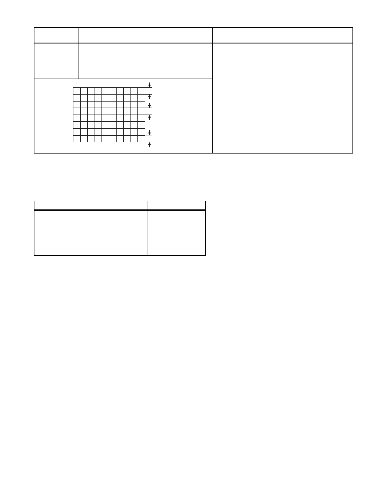
Item
V. S-SHAPE
CORRECTION &
LINEARITY
Measuring
instrument
Signal
generator
Remote
control unit
Test point Adjustment part Description
[4.DEF]
13.V-S. CR
14.V-LIN
• When the vertical linearity has been deteriorated
remarkably, perform the following steps.
(1) Receive a PAL cross-hatch signal.
(2) Select < 14.V-LIN >.
(3) Set the initial setting value of < 14.V-LIN >.
(4) Select < 13.V-S.CR >.
TOP
(5) Set the initial setting value of < 13.V-S.CR >.
(6) Adjust < 14.V-LIN > and < 13.V-S.CR > so that the
spaces of each line on TOP, CENTER, and
CENTER
BOTTOM become uniform.
Note :
Do not adjust "ZOOM" & "16 : 9" mode.
BOTTOM
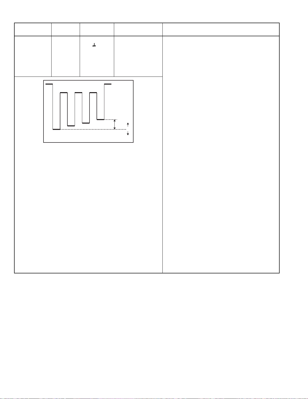
4.7.7 AUDIO
• Do not touch < 3. AUDIO > adjustment of the SERVICE MENU as it requires no adjustment.
If values had changed for the some reason, set the initial values in the following table.
3. AUDIO
Setting item Variable range Ini tial setting value
1. ERR LIMIT 0000~00FF 0010
2. A2 ID THR 0000~00FF 0019
3. SYSTEM B/G→I→D/K→M ---
4. SUB BASS -03~03 0001
5. SUB TREBLE -03~03 0001
(No.52198)1-29
Page 30

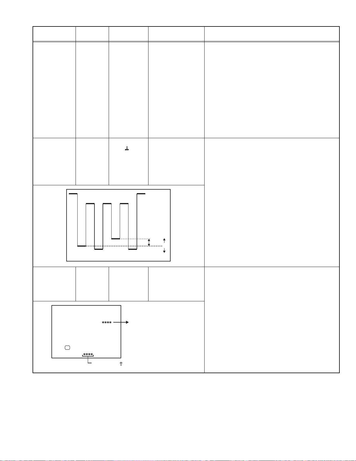
4.7.8 PURITY AND CONVERGENCE
PURITY ADJUSTMENT
(1) Demagnetize CRT with the demagnetizer.
(2) Loosen the retainer screw of the deflec tion yoke.
(3) Remove the wedges.
WEDGE
DYNAMIC CONVERGENCE
ADJUSTMENT
PURITY MAGNET(P)
(4) Input a green raster signal from the signal generator, and
turn the screen to green raster.
(5) Move the deflection yoke backward.
(6) Bring the long lug of the purity magnets on the short lug and
position them horizontally. (Fig.2)
(7) Adjust the gap between two lugs so that the GREEN
RASTER will come into the center of the screen. (Fig.3)
(8) Move the deflection yoke forward, and fix the position of the
deflection yoke so that the whole screen will become green.
(9) Insert the wedge to the top side of the deflection yoke so that
it will not move.
(10) Input a crosshatch signal.
(11) Verify that the screen is horizontal.
(12) Input red and blue ra ste r signal s, and make sure that puri ty
is properly adjusted.
CRT
46
CRT SOCKET PWB
DEF. YOKE
P/C MAGNETS
P/C MAGNETS
P :
PURITY
MAGNET
4 : 4 POLES (convergence magnet)
6 : 6 POLES (convergence magnet)
Fig.1
PURITY MAGNETS
Short lug
Long lug
Bring the long lug over the short lug and
position them horizontally.
Fig.2
( FRONT VIEW )
GREEN RASTER
CENTER
Fig.3
1-30 (No.52198)
Page 31

PURITY ADJUSTMENT
(1) Input a crosshatch signal.
(2) Using 4-pole convergence magnets, overlap the red and
blue lines in the center of the screen (Fig.1) and turn them
to magenta (red/blue).
(3) Using 6-pole convergence magnets, overla p the magenta
(red/blue) and green lines in the center of the screen and
turn them to white.
(4) Repeat 2 and 3 above, and make best convergence.
• After adjustment, fix the wedge at the original position.Fasten
the retainer screw of the deflection yoke.Fix the 6 magnets with
glue.
DYNAMIC (periphery) CONVERGENCE ADJUSTMENT
After adjusting purity & static convergence.
(1) Move the deflection yoke up and down to adjust the pin
cushion distortion in the screen top and bottom. (See Fig. 2)
( FRONT VIEW )
Fig.1
( FRONT VIEW )
TOP
BOTTOM
Fig.2
(2) Move the deflection yoke left to right to overlap the lines in
the periphery, and match the Yv(VR1).
(As shown in Fig. 4)
(3) Using the VR1 on the deflection yoke, match the YH
(CROSS). (See Fig. 3 and 6)
(4) Using the VR2 on the deflection yoke, match the YH (BOW).
(See Fig. 3 and 6)
(5) Repeat the steps 1 and 4 and obtain an optimum
convergence.
(6) Differential(XV) coil ADJUSTMENT.
In case where the horizontal lines of red and blue around the
center of both sides of the picture as shown in Fig. 5, adjust
the XV difference by using the differential coil (XV coil) on
the top of the deflection yoke (Fig. 6) so as to minimize the
XV difference.
CRT
FRONT
YHC
(VR2)
XV COIL
YV
(VR1)
( FRONT VIEW )
RED
BLUE
GREEN
RED
( FRONT VIEW )
GREEN
BLUE
RED
(FRONT VIEW)
YH
GREEN
YH
Fig.3
YV
YV
Fig.4
BLUE
REDBLUE GREEN
BLUE
GREEN
RED
RED
GREEN
BLUE
BLUE
GREEN
RED
RED
GREEN
BLUE
Fig.6
Xv
BLUE (RED)
GREEN
RED(BLUE)
Fig.5
(No.52198)1-31
Page 32

SCHEMATIC DIAGRAMS
COLOUR TELEVISION
HV-29WH21, HV-29WH21/A,
HV-29WH21/E, HV-29WH51/S,
HV-29WH71/G
RM-C1351
[HV-29WH21]
[HV-29VH21]
RM-C1353
[HV-29WH51]
RM-C1350
[HV-29WH71]
CD-ROM No.SML200311
[HV-29WH21]
[HV-29WH51]
[HV-29WH71]
BASIC CHASSIS
ML
[HV-29VH21]
COPYRIGHT © 2003 VICTOR COMPANY OF JAPAN, LIMITED
No.52198
2003/11
Page 33

Page 34

HV-29WH21, HV-29VH21
/A
, HV-29WH21
/E
HV-29WH51
/S
, HV-29WH71
/G
STANDARD CIRCUIT DIAGRAM
NOTE ON USING CIRCUIT DIAGRAMS
1.SAFETY
The components identified by the symbol and shading are
critical for safety. For continued safety replace safety ciritical
components only with manufactures recommended parts.
2.SPECIFIED VOLTAGE AND WAVEFORM VALUES
The voltage and waveform values have been measured under the
following conditions.
(1)Input signal : Colour bar signal
(2)Setting positions of
each knob/button and
variable resistor
(3)Internal resistance of tester
(4)Oscilloscope sweeping time
(5)Voltage values
Since the voltage values of signal circuit vary to some extent
according to adjustments, use them as reference values.
: Original setting position
when shipped
: DC 20k
: H
: V
: Othters
: All DC voltage values
/V
20µs / div
5ms / div
Sweeping time is
specified
3.INDICATION OF PARTS SYMBOL [EXAMPLE]
In the PW board
: R1209
R209
Type
No indication
MM
PP
MPP
MF
TF
BP
TAN
(3)Coils
No unit
Others
(4)Power Supply
Respective voltage values are indicated
(5)Test point
: Test point
(6)Connecting method
: Ceramic capacitor
: Metalized mylar capacitor
: Polypropylene capacitor
: Metalized polypropylene capacitor
: Metalized film capacitor
: Thin film capacitor
: Bipolar electrolytic capacitor
: Tantalum capacitor
: [µH]
: As specified
: B1
: 9V
: Only test point display
: Connector
: Receptacle
: Wrapping or soldering
: B2 (12V
: 5V
)
4.INDICATIONS ON THE CIRCUIT DIAGRAM
(1)Resistors
Resistance value
No un i t :[
K
M
Rated allowable power
No indication : 1/16 [W]
Others : As specified
Type
No indication
OMR
MFR
MPR
UNFR
FR
Composition resistor 1/2 [W] is specified as 1/2S or Comp.
(2)Capacitors
Capacitance value
1 or higher : [pF]
less than 1
Withstand voltage
No indication : DC50[V]
Others : DC withstand voltage [V]
AC indicated
Electrolytic Capacitors
47/50[Example]: Capacitance value [µF]/withstand voltage[V]
]
]
: [k
: [M
]
: Carbon resistor
: Oxide metal film resistor
: Metal film resistor
: Metal plate resistor
: Uninflammable resistor
: Fusible resistor
: [µF]
: AC withstand voltage [V]
(7)Ground symbol
: LIVE side ground
: ISOLATED(NEUTRAL) side ground
: EARTH ground
: DIGITAL ground
5.NOTE FOR REPAIRING SERVICE
This model's power circuit is partly different in the GND. The
difference of the GND is shown by the LIVE : ( ) side GND and the
ISOLATED(NEUTRAL) : ( ) side GND. Therefore, care must be
taken for the following points.
(1)Do not touch the LIVE side GND or the LIVE side GND and the
ISOLATED(NEUTRAL) side GND simultaneously. if the above
caution is not respected, an electric shock may be caused.
Therefore, make sure that the power cord is surely removed from
the receptacle when, for example, the chassis is pulled out.
(2)Do not short between the LIVE side GND and ISOLATED(NEUTRAL
side GND or never measure with a measuring apparatus measure
with a measuring apparatus ( oscilloscope, etc.) the LIVE side GND
and ISOLATED(NEUTRAL) side GND at the same time.
If the above precaution is not respected, a fuse or any parts will be broken.
Since the circuit diagram is a standard one, the circuit and
circuit constants may be subject to change for improvement
without any notice.
NOTE
Due improvement in performance, some part numbers show
in the circuit diagram may not agree with those indicated in
the part list.
When ordering parts, please use the numbers that appear
in the Parts List.
No.52198
)
2-1
Page 35

CONTENTS
SEMICONDUCTOR SHAPES ......................................................................2-2
BLOCK DIAGRAM........................................................................................2-3
CIRCUIT DIAGRAMS....................................................................................2-5
MAIN PWB CIRCUIT DIAGRAM ................................................................................................................ 2-5
POWER & DEF PWB CIRCUIT DIAGRAM ................................................................................................. 2-9
CRT SOCKET PWB CIRCUIT DIAGRAM ..................................................................................................2-11
MICOM/100Hz PWB CIRCUIT DIAGRAM ................................................................................................ 2-13
A V JACK PWB CIRCUIT DIAGRAM......................................................................................................... 2-15
FRONT CONTROL PWB CIRCUIT DIAGRAM.......................................................................................... 2-17
PATTERN DIAGRAMS .............................................................................. 2-21
MAIN PWB P A TTERN .............................................................................................................................. 2-21
POWER & DEF PWB PATTERN............................................................................................................... 2-23
A V JACK PWB P A TTERN ........................................................................................................................ 2-25
FRONT CONTROL PWB P A TTERN ......................................................................................................... 2-25
CRT SOKET PWB P A TTERN ................................................................................................................... 2-26
MICOM/100Hz PWB P A TTERN ................................................................................................................ 2-27
USING P.W. BOARD
PWB ASS'Y name HV-29WH21 HV-29VH21/A HV-29WH21/E HV-29WH51/S HV-29WH71/G
M AIN P.W. BOARD SML-1501A-H2 SML1511A-H2 SML-1510A-H2 SML-1508A-H2 SML-1503A-H2
POWER & DEF P.W. BOA RD SML- 2501A -H2
AV JACK P.W . BOARD SML 0J501A-H2
FRONT CONTROL P.W. BOARD SML-8501A-H2
CRT SOCKET P.W. BOARD SML-3501A -H2
M ICOM/100Hz P.W. BOARD SML0Z502A-H2
←
←←
←←←←
←←←←
←←
SML-2503A-H2 SML-2501A-H2
SML0J503A-H2
SML0Z501A-H2
←
←
←
SEMICONDUCTOR SHAPES
TRANSISTOR
BOTTOM VIEW FRONT VIEW TOP VIEW
CHIP TR
E
C
B
ECB
IC
BOTTOM VIEW FRONT VIEW TOP VIEW
OUT
E
IN
IN OUTE
CHIP IC
N
N
B
(G)E(S)C(D)
TOP VIEW
1 N
1
ECB
ECB
1
1 N
C
BE
N
2-2
N
1
N
N
No.52198
Page 36

BLOCK DIAGRAM
VIDEO 1
VIDEO 2
VIDEO 3
Y/C 1
V 1
L/R 1
V 2
L/R 2
V3/Y
CB
CR
L/R 3
TU001
TUNER
VTV
SIF
TV L/R
VTV
V 1
V 2
V3/Y
V 4
Y/C 1
Y/C 4
L/R
L/R 1
L/R 2
L/R 3
L/R 4
MULTI SOUND
PROCESSOR
IC201
AV SW
IC101
V
Y
L/R
SP L
SP R
VIDEO 4
L/R
L/R
IC601
PRE AMP
L/R
AUDIO OUT
IC551
ROTATION
IC651
IC701
MEMORY
L/R
ROTATION
COIL
FRONT
CONTROL
PWB
(1/2)
L
R
HEAD
PHONE
Y/C 4
V 4
L/R 4
KEY
MI-COM / 100Hz PWB
ROTAT
CV/Y
C
C
IC201
DOUBLE
SCAN
CONVERTER/
IC301
RGB PROCESS/
DEFLECTION
CONTROL
V2 SYNC
H2 SYNC
IC202
MICRO
COMPUTER/
TELETEXT
DECODER
KEY
VIDEO PROCESS
REMO
Y
Cb
Cr
HD
VD
R/G/B,VM
CVBS
CRT SOCKET PWB
B
R
G
VM
IC203
B OUT
IC202
R OUT
IC201
G OUT
Q108 / Q109
VM OUT
CRT
VM COIL
LINE
OUT
V2 OUT
L/R2 OUT
AV JACK
PWB
AC IN
MAIN PWB
FRONT
CONTROL
PWB
(2/2)
POWER SW
No.52198 No.521982-42-3
IC001
REMOCON
RECEIVER
FUSE
REMO
FILTER
POWER
&
DEF. PWB
RECTIFIER
Q501
H.DRIVE
SW. TRANS
B1
Q521
H.OUT
IC401
V.OUT
T551
HVT
V.DY
H.DY
SCREEN
HV
FOCUS
Page 37

CIRCUIT DIAGRAMS
MAIN PWB CIRCUIT DIAGRAM (1/2
AFC
32V
V_TV
AGC
5V
SDA1
SCL1_2
Y014
R004
R005
10/50
0
0
C002
10/50
80%
C007
Y013
OPEN
L001
C005
1000/16
OPEN
C011
10/50
C012
.01
NQR0389-003X
K002
L003
10
L002
10
27
R001
OPEN
QAU0197-002
QQR1199-001
C017
.1/16
C008
OPEN
C009
OPEN
C006
.01
K001
C004
.1/16
R003
R002
C003
C001
.0022
LC005
C010
1/10
C014 C015
.1/16 10/50
NQR0389-003X
100
100
OPEN
MAIN PWB ASS'Y (1/2
SML-1501A-H2 (HV-29WH21
SML-1511A-H2 (HV-29VH21/A
SML-1510A-H2 (HV-29WH21/E
SML-1508A-H2 (HV-29WH51/S
SML-1503A-H2 (HV-29WH71/G
)
R007
2.2k
Y001
OPEN
R006
0
R008 R010
1k 27
R012
MAIN PWB (2/2)
H/P_R
Y605
R606
DI
1k
C604C601
.0151/50
R608
3.3k
C606
.015
R609
3.3k
OPEN
Q644
OPEN
R690
OPEN
QUY153-050Y
.0012
C607
.0012
Q621
PNP
R621
100k
Q622
OPEN
D621
OPEN
C605
L650
BW
R611
2.2K
R622
OPEN
H/P_L
R683
OPEN
R610
2.2K
C681
OPEN
BA4558F-X
IC601
BA4558F-X
C624
33/50
IC601
R662
OPEN
DTC323TK-X
R623
R624
R612
R663
OPENOPEN
R625
OPEN
220
R613
220
Q623
D625
OPEN
R684
OPEN
Q681
OPEN
0
0
C683
OPEN
C123
.001
C131
.001
C130
.001
Y604
OPEN
D628
OPEN
PROTECT
MA3120/M/-X
CH
CH
CHCH
GND
C623
1000/25
D629
DI
C105
10/50
C106
.1/16
D204
C122
.001
D205
MA3120/M/-X
8V
C612
Y004
0
Q632
PNP
R638
R637
47K
27K
RTV
LTV
D681 R686
OPEN OPEN
C650
100/16
R650
10k
R605
1k
N
R604
3.3K
R601
33k
C603
100/16
R603
10K
R602
33k
C602
R607
1/50
3.3k
N
N
D623
D624
DI
A_MUTE
A.MUTE
D622
OPEN
D630
D633
DI
DI
9V
R009
330
Q001
NPN
.0047
270
GND
C127
C102
10/50
L101
QRN143J-0R0X
C013
C016
.0047 10/50
0
NQR0389-003X
Q002
NPN
R011
1k
C119
2p
C120
2p
K101
C117
C118
OPEN
C129
CH
CH
CE42546-001Z
C101
.1/16
.01
.01
X101
10/50
L
R
C128 C126
.1/16 .1/16
C219C220
1/10
1/10
R108 R109
100 100
IC101
MSP3413G-QA-B3
10/50
C125
C124
10/50
MULTI-SOUND PROCESS
R106
0
R107
0
R103
OPEN
R104
OPEN
R102R101
100100
D_GND
)
SCL1_2
SDA2
)
)
)
TU001-18
3
K102
NQR0389-003X
LC101
NQR0431-001X
C104
100/16
C103
.1/16
4.7
L102
QQL244K-4R7Z
C121
.01
R105
Q101
UN2213-X
RESET
10k
Y002
BW10
D631
DI
MSP_RST
6V
)
)
No.52198 No.521982-5 2-6
C682
IC681
OPEN
R682
OPEN
R685
OPEN
C687
OPEN
R688
OPEN
R689
OPEN0OPEN
IC651
AN5277
AUDIO
OUT
R651
C610
10/16
4.7k
N
R653
100K
C608
.022
R654
C609
100K
.022
C611
R652
10/16
4.7k
N
R626
OPEN
R628
OPEN
Q626
OPEN
OPEN
D632
W_ON/OFF
R681
R687
OPEN
N
C685
OPEN
C688
C651
R655
10k
C652
10/50
C653
OPEN
Q624
DTC323TK-X
Q625
OPEN
R627TU001
OPEN
Q627
OPEN
OPEN
N
C689
OPEN
C654
100/50
R656
OPEN
Y601 Y602
QQR1113-001Z
0
R629 R632
10k 8.2k
Q628
UN2213-X
D626
DI
C684
OPENOPEN
C686
OPEN
R657
10k
R630
OPEN
R631
C665
OPEN
47k
C643
OPEN
C644
OPEN
.22/50
.22/50
Y603
OPEN
C655
C656
Q641
OPEN
MUTING
A2_GND
R635
8.2k
Q629
NPN
Y003
OPEN
R641
OPEN
R658
QRE121J-8R2Y
10/50
D651
C666
C657
2200/35
MA3330/L/-X
R642
OPEN
Q643
OPEN
MUTING
R643
OPEN
Q642
OPEN
MUTING
QETM1VM-228
QRE121J-8R2Y
C658
OPEN
C659
OPEN
R659 D652
OPEN OPEN
R661
R633
OPEN
Q631
OPEN
R636
OPEN
Q630
OPEN
.22/50
.22/50
C660
C661
R660
18K
K641
OPEN
R644
OPEN
K642
OPEN
R645
OPEN
HS651
LC32265-001A
R634
OPEN
C667
OPEN
C641
OPEN
R672
OPEN
TH671
OPEN
D653
A_GND
MA3330/L/-X
R671
OPEN
R673
C642
OPEN
C663
QUY153-050Y
C664
QUY153-050Y
C662
OPEN
C692 C691
OPEN .001
C671
OPEN
D627
OPEN
6V
A_MUTE
W_ON/OFF
PROTECT
A.MUTE
MSP_RST
SDA2
SCL1_2
FIX_GND
J001
OPEN
L_OUT
A_GND
R_OUT
CN0SP
OPEN
CN00A
QGA2501C5-03Z
CN0SW
OPEN
A2_GND
A_VCC
A_PROT
STB_5V
P_ON/OFF
AMP_MUTE
6V
A_MUTE
W_ON/OFF
PROTECT
A.MUTE
MSP_RST
SDA2
SCL1_2
MAIN PWB (2/2)
NOT USED
FRONT CONTROL
PWB
NOT USED
PIN NO.
IC101
1 NC
2 4
3 3.9
4 NC
5 NC
6 NC
7 NC
8 NC
9 NC
10 NC
11 4.9
12 4.9
13 4.9
14 0
15 0
16 0
17 NC
18 NC
19 NC
20 NC
21 4.9
22 NC
23 NC
24 0
25 0
26 4.4
27 4.4
28 4.4
29 NC
30 0
31 NC
32 NC
33 NC
34 NC
MAIN PWB
(2/2)
35 0
36 3.7
37 3.6
38 NC
39 8
40 7.1
41 NC
42 NC
43 0
44 0
45 3.6
46 NC
47 NC
48 NC
49 0
50 NC
51 NC
52 0
53 NC
54 NC
55 0
56 4.4
57 4.4
58 2.5
59 NC
60 3.6
61 0
62 0
63 NC
64 NC
65 4.9
66 4.9
67 1.4
68 1.4
69 2.5
70 0
71 2.2
72 2
73 NC
74 NC
75 NC
76 NC
77 4.8
78 0
79 2.4
80 4.9
VOLTAGE(V
)
PIN NO.
IC601
1 4.4
2 4.4
3 4.4
4 0
5 4.4
6 4.4
7 4.4
8 8.9
IC651
1 NC
3 0
5 29.3
7 0
9 0
11 N C
13 14.7
15 0.5
17 0
19 30.5
21 16.6
23 14.6
TU001
1 2.4
2 3.8
3 0
4 4.4
5 4.4
6 NC
7 4.8
8 NC
9 31.5
10 NC
11 4.3
12 4.3
13 8.9
14 1.5
15 0
16 3
17 2.4
18 2.8
19 0
20 4.8
21 0
22 8.9
Q001
E 2
C 6.5
B 2.7
Q002
E 5.9
C 8.9
B 6.5
Q101
E 0
C 4.9
B 0
Q621
E 0.2
C -1.1
B 0.7
Q623
E 0
C 0
B -1.1
Q624
E 0
C 0
B -1
Q632
E 6
C -5.3
B 6.5
Q628
E 0
C 4
B 0.6
Q629
E 0
C 0
B 0.5
VOLTAGE(V
)
Page 38

MAIN PWB CIRCUIT DIAGRAM (2/2
NOT USE
CN0C1
QGA2501F1-06
220
220
220
R701 R705
OPEN 220
FRONT CONTROL
PWB
AV JACK PWB
IC201-23
1.5
QGA2501C1-12
CN001
QGB1505J1-35
W_ON/OFF
PROTECT
32V
A_VCC
A2_GND
STB_5V
IC201-36,40,43
3
GND
CN00F
5V
9V
8V
6V
D701
MA3056/M/-X
D702
MA3056/M/-X
R274
2.2k
OPEN
Y015
Y019
*
Y017 C213
Y005
OPEN
Y010
*
D981
DI
3
R702
IIC_FREE
SDA0
R273
2.2k
Y016
OPEN
OPEN
LC003
QQR1199-001
Y006 Y007
*
OPEN
Y009
*
LC001
*
CN002-5
R703
SCL0
R704
SDA1
MA3056/M/-X
MA3056/M/-X
SCL1_2
R272
33k
V
R207R206R205
757575
D703
LC002
Y008
)
D704
*
*
R271
33k
NCF31AZ-105X
MAIN PWB (1/2
S_4
A.MUTE
V_TV
V_TV
AFC
Cr
Cb
1.7
AGC
AFC
AGC
V3/Y_IN
LINEOUT
V3/Y_OUT
Q210
MUTING
CN002-24
LRLTV
L
R
R4
L4
V4
Y4
C4
V1
Y1
C1
L3
R3
S_1
V2
R2
L2
L1
R1
PNP
LTV
L3
V3/Y_OUT
R3
V2
L2
R2
V1
L1
C245
10/50
Y1
R1
C1
S_1
R260
100k
SDA1
SCL1_2
SDA2
SCL1_2
SDA2
SDA1
C223
NCF31AZ-105X
C224
H/P_L
H/P_R
AV_LINK
W_ON/OFF
PROTECT
P_ON/OFF
D982
DI
CN003 CN004 CN005
QGB1506L1-16 QGB1506L1-16 QGB1506L1-16
CN002-10
2
)
RTV
RTV
MSP_RST
R215
2.2k
D219
ZD12
R217 R218
2.2k 33k
MSP_RST
R209
2.2k
R258
82k
A_MUTE
P_ON/OFF
AMP_MUTE
A.MUTE
A.MUTE
R210R208
33k2.2k
NCF31AZ-105X
NCF31AZ-105X
NCF31AZ-105X
R216
33k
NCF31AZ-105X
R259 D207
82k ZD12
P_ON/OFFL4A_MUTE
C202
10/50
C204
C205
C206
10/50
C207
C209
C210
.01
AMP_MUTE
R211
33k
C208
OPEN
Q211
DTC323TK-X
MUTING
A_PROT
A_PROT
R240
100
CH
D220
ZD12
R275
390
R276
390
Q214
DTC323TK-X
MUTING
CN002-25
1.7
1.8
H/P_R
H/P_L
H/P_L
H/P_R
R234
2.2k
R235
NCF31AZ-105X
R236
R237
2.2k
CH
C217
OPEN
R213
100
R243
D218
ZD12
R244
R245
R246
R247
D215
ZD12
C226
10/50
C227
10/50
CN002-26
R212
100
0.01
0.01
33k
33k
C246
C247
L_OUT
L_OUT
100
100
100
100
100
D206
ZD12
GND
A_GND
R_OUT
R_OUT
A_GND
NCF31AZ-105X
C215
10/50
C216
D217
ZD12
R296
100
C218
OPEN
GND
NC
Cb
C214
OPEN
100
R238
CH
D201
ZD12
CN002-72,84
3
EW
V3/Y_OUT
CH
V3/Y
100
R239
HFLB
CrEWHFLB
100
R264
R266
100
C222
V4
GND
HD
SC_B1
NC
HD
CXA2089Q-X
VIDEO/AUDIO
SELECT
R268
100
C240
OPEN
C201
10/50
Y4
10/50
SC_R1
SC_G1
ABL
NC
NC
ABL
IC201
R270R269R267R265
100100100100
D202
ZD12
C225
.01
R4
C4
*
LC004
Y019
LC001
LC002
Y007
Y008
Y009
Y010
GND
SC_YS1
VD+CrVD-
C561
NDC31HJ-390X
VD+
VD_
R295
33K
D216
ZD12
D203
ZD12
SML-
1501A 1503A
OPEN
QQR1199
-001
QQR1199
-001
OPEN
OPEN
OPEN
OPEN
R281 R282
1k 1k
QQR1199
QQR1199
MICOM/100Hz PWB
GND
GND
VPROTCbHPROT
M_C
M_CV/Y
NC
Y011
OPEN
C562
OPEN
VPROT
HPROT
R277
C228
100
.01
C229
10/50
R279
5.6k
N
C231
10/25
R280
5.6k
V_TV
IC901
AN78L08-T
C901
100/16
SML-
SML-
SML-
1508A
QQR1199
-001
-001
0
QQR1199
-001
QQR1199
-001
-001
OPEN
OPEN
OPEN OPEN OPEN
OPEN
OPEN
OPEN OPEN
OPEN
OPEN OPEN OPEN
0 OPEN OPENOPEN
1510A
OPEN OPEN
QQR1199
-001
QQR1199
-001
OPEN
QQR1199
-001
S_CV
NC
NC
LC004
*
Y018
OPEN
QRT039J-3R3
C230
10/25
R286
100
C237
NCF31AZ-105X
C238
NCF31AZ-105X
SML1511A
QQR1199
-001
QQR1199
-001
OPEN
OPEN
R713
R289
100
R290
100
3.3
N
GND
Q216
NPN
BUFFER
R278
2.2K
C234
.01
6V
6V
Y012
OPEN
D208
ZD12
470/16
C902
.1/16
6V
6V
GND
GND
C908
220/16
C235
100/16
Q217
KTC3199/YG/-T
R287
150
R1/2
C236
LINEOUT
R288
75
12V
GND
C903
100/16
VM
Rout
Gout
GND
5V
12V
12V
NC
SVM
R
L
RTV
LTV
5V
NC
ROUT
GOUTIKAV_LINK
Bout
GND
YS2
C.V
BOUT
SDA2
SCL1_2
R708
0
Q701
RESET
C904
1
NCF31AZ-105X
C905
10/50
AV_LINK
D705
PNP
/10
IK
NC( PWMV)
ROTATE
R552
10
R558
5.6K
C551
.22/16
C552
.22/16
DI
C906
2.2
/6.3
NCB20JK-225X
POWER & DEF PWBPOWER & DEF PWB
NC
CN002
R551
120K
R553
68K
80%
80%
K552
QQR0621-002Z
C502
OPEN
IC501
BA10324AF-XE
R709
2.2k
C702
.1/16
R710
100k
Sub
Vin
VoNCGND
C907
470p
IC551
LA6515
R554
5.6K
Cn Cont
CH
GND
GND
R560
4.7K
C501
OPEN
R502
12k
R503
12K
C503
1000p
C703
OPEN
IC902
MM1565AF-X
V_PULSE
MSP_RESET
MSP_RSTVSHS
AGC
RT_GND
R501
12k
CH
Q702
NPN
RESET
H_PULSE
AGC
ROTATION
R555
150K
R559
33K
R509
R514
3.9k
R505
120k
AFC
100K
C506
AFC
NC
R556
.22/16
.22/16
RGB_5V
R518
.1/16
R504
12K
C509
.1/16
A_PROT
A_PROT
R557
10
C554
C555
12k
C504
.1/16
GND
VCC
C507
R517
12k
NC
C505
.1/16
.1/16
AMP_MUTE
NC
AMP_MUTE
A_MUTE
80%
80%
R506
4.7k
R512
15k
100/16
C508
R519
4.7k
R520
33k
AUDIO_MUTE
R516
12k
R522
OPEN
MICOM/100Hz PWB
SDA1
SCL1_2
SDA2
GND
GND
RESET
IIC_FREE
W_ON/OFF
IIC_FREE
SDA2
W_ON/OFF
R507
27k
R511
6.8k
R513
3.3k
R515
33k
C512
OPEN
SDA1
K551
QQR0621-002Z
C302
C301
OPEN
OPEN
CORRECT
R521
47k
R531
4.7k
R534
OPEN
Q503
OPEN
INV
SCL1_2
Q502
NPN
R525
22k
EHT
RESET
C553
47/25
RT_12V
R510
56k12k
MAIN PWB ASS'Y (2/2
SML-1501A-H2 (HV-29WH21)
SML-1511A-H2 (HV-29VH21/A)
SML-1510A-H2 (HV-29WH21/E)
SML-1508A-H2 (HV-29WH51/S)
SML-1503A-H2 (HV-29WH71/G)
GND
SDA0
SCL1_2
SDA0
BOUT
GOUT
ROUT
SVM
D501
R526 R527
68k
R528
4.7k
R533
2.7k
H/P_DET
SCL0
HP_DET
C701
C705
OPEN
DI
C510
.033/25
C511
OPEN
SCL0
C308
.22/16
KEY1
R529
47K
D530
OPEN
KEY1
C309
.001
R535
OPEN
R314
22k
R530
150k
KEY2
STB3.3V
KEY2
Vcc
A0
Vcc
A0
56k
CH
PROTECT
R706
R532
C530
OPEN
C513
OPEN
GND
PROTECT
KEY3
PW_ON/OFF
GND
C711
.1/16
KEY3
P_ON/OFF
SCL0
SDA0
100.1100
TEST
SCL0
SDA0Vss
A2
A1
R711
OPEN
TEST
SCL0
SDA0Vss
A2
A1
C303
220/16
R313
390
R1/2
Q305
KTC3199/YG/-T
R315
68
R524R523
220k220k
R536
150K
C515
.01
Q501
EHT
12k
CORRECT
NPN
R537
12k
R540
OPEN
C514
R539
OPEN
OPEN
PW_LED
STB_5V
ECO
ROTATION
LED
REMOCON
ROTATE
R707
IC701
AT24C32A-29WH21
EEPROM
SCL0
SDA0
R712
OPEN
IC702
OPEN
EEPROM
C304
.01
EW
R311
390
R1/2
C310
.22/16
R312
68
ABL
R541
OPEN
Q505
OPEN
RESET
VS
R538
OPEN
HS
Q504
OPEN
INV
HD
VD+
VD_
VPROT
HPROT
HFLB
CN002
QGC2507C1-96
REMOCON
IK
LED
HP_DET
REMOCON
KEY3
KEY2
KEY1
L_OUT
A_GND
R_OUT
S_4
PROTECT
W_ON/OFF
D502
DI
D503
DI
D504
DI
CN00B
QGF1220C2-19
STBY_5V
GND
GND
P.ON/OFF
TIMER_ON/OFF
ECO_ON/OFF
3D_ON/OFF
ECO
FRONT CONTROL
REMOCON
PWB
KEY3
KEY2
KEY1
L_OUT
A_GND
R_OUT
S_4
12V
CN0RT
QGA2501C5-03Z
CN00R
QGA2501C1-10
CRT SOCKET PWB
PIN NO.
VOLTAGE(V
3 0
4 0
5 3.2
6 3.2
7 0
8 3.2
IC901
1 11.9
2 8
3 0
IC902
1 4.9
2 NC
3 0
4 3.4
5 6.5
6 0
7 6.5
Q210
E 6.1
C -0.7
B 0.2
Q211
E 0
C 0
B -0.7
Q214
E 0
C 0
B -0.7
Q216
E 3.9
C 8.9
B 4.6
Q217
E 8.9
C 3.9
B 4.6
Q305
E 1.1
C 4.9
B 1.8
Q501
E 0
C 11.5
B -1.4
Q502
E 2.2
C 3.8
B 2.8
Q701
E 6.3
C 0.6
B 6.5
Q702
E 3.2
C 9
B 0.6
CN1002
1 0
2 NC
3 2.3
4 2.2
5 1.3
6 NC
7 NC
8 1.6
9 NC
10 2
11 1.9
12 NC
13 0
14 0.3
15 NC
16 NC
17 6.5
18 6.5
19 0
)
PIN NO.
20 0
21 11.9
22 4.7
23 0
24 2.6
25 2.7
26 2.8
27 0
28 1.5
29 NC
30 0
31 3.2
32 3.2
33 NC
34 NC
35 NC
36 3.2
37 0
38 0
39 3.7
40 4.3
41 3.2
42 3.2
43 3.2
44 2.4
45 0
46 0
47 4.8
48 5.4
49 2.2
50 0
51 0
52 0
53 3.2
54 3.2
55 3.2
56 3.2
57 0
58 4.4
59 4.4
60 0
61 3.2
62 0.1
63 0
64 0
65 1.5
66 3.2
67 0
68 0
69 0
70 0
71 0
72 3.9
73 NC
74 0
75 NC
76 11.9
77 0
78 0
79 6.5
80 6.5
81 0
82 3.6
83 0
84 4.3
85 0
86 4.2
87 0
88 0
89 0
90 2.3
91 0
92 0
93 2.9
94 3.4
95 2.9
96 0
VOLTAGE(V
)
)
PIN NO.
VOLTAGE(V
IC201
1 3.9
2 4.4
3 3.9
4 4.4
5 4.4
6 NC
7 NC
8 3.9
9 4.4
10 3.9
11 4.4
12 4.4
13 NC
14 7.9
15 3.9
16 4.4
17 3.9
18 4.4
19 4.4
20 NC
21 0
22 4.4
23 4.4
24 4.4
25 0
26 4.4
27 4.4
28 NC
29 NC
30 NC
31 NC
32 NC
33 3.6
34 8.9
35 0
36 5
37 4.4
38 4.4
39 4.4
40 4.6
41 4.4
42 NC
43 4.3
44 0
45 4.2
46 0
47 3.9
48 4.4
IC501
1 5.7
2 5.6
3 5.6
4 11.9
5 3.3
6 3.2
7 2.8
8 2.2
9 2.2
10 2.3
)
11 0
12 2.8
13 2.8
14 5.5
IC551
1 6.5
2 6.5
3 6.5
4 6.4
5 0
6 6.4
7 6.5
8 6.3
9 6.3
10 11.9
IC701
1 0
2 0
No.52198 No.521982-82-7
Page 39

POWER & DEF PWB CIRCUIT DIAGRAM
FRONT CONTROL
)
PIN NO.
VOLTAGE(V
IC401
1 NC
2 -14.9
3 0
4 14.9
5 0.5
6 0.5
7 14.8
8 12.7
9 14.9
10 -12.5
IC461
1 3.4
2 1
3 2
4 0
5 5.7
6 3.4
7 10.5
8 11.9
IC901
1 0.7
2 0.1
3 138.4
4 18.2
5 3
IC931
1 0.1
2 0
3 2.3
4 0.1
5 0
6 NC
7 154.2
8 154.2
IC951
1 140.9
2 12.1
3 0
IC961
1 14.4
2 11.9
3 0
IC962
1 11.9
2 9
3 0
PC901
1 13.2
2 12.1
3 0
4 2.8
PC931
1 4.8
2 3.8
3 0.8
4 23
Q461
S 0.7
D 15
G 10.5
IC401-3
90
PWB
PIN NO.
VOLTAGE(V
Q462
E 0
C 2.4
B 0.2
Q463
E 1
C 11.9
B 0.9
Q464
E 2.4
C 0
B 2.4
Q481
E 0
C 0
B 1.7
Q482
E 0
C 2.4
B 0
Q501
S 0
D 35.2
G 1.3
Q521
E 0
C 206
B 0
Q561
E 1.4
C 10
B 1.9
Q562
E 9.5
C 11.9
B 10
Q563
E 1.3
C 333
B 1.9
Q581
E 140.8
C 0
B 140.4
Q582
E 0
C 2.4
B 0.4
Q941
E 0
C 0.6
B 0.1
Q942
E 0
C 1.2
B 0.6
Q943
E 0
C 9
B 0.1
QGZ5004C1-02
CN00W
QGA7901C1-02
60
POWER & DEF PWB ASS'Y
SML-2501A-H2 (HV-29WH21, HV-29VH21/A, HV-29WH51/S, HV-29WH71/G
SML-2503A-H2 (HV-29WH21/E
!
L 01
!
TH901
QAD0145-2R3
CNDEG
C903
OPEN
)
IC401-4,10
Y904
Y905
!
QQR1433-001
!
C902
QFZ9075-104
QFZ9072-104
C994
!
C995
470p
QCZ9079-471
OPEN
LF901
Y906
Y907
QRF154K-1R8
OPEN
HS901
LC30774-001A
!
OPEN
OPEN
R903
1.8
15W
IC901
STR-F6256S-F7
DRIVE
IC401-5,6
0.6
QFZ9075-473
FB/OLP
OCP/INH
R902
3.3
5W
QRF054K-3R3
C936
150p
C904
!
.0047
QCZ9054-472
D901
D3SB60
QCZ9054-472
D911
MTZJ15B
VIN
K902
OPEN
D
S/GND
BW
D909
C914
220p
D910
MTZJ15B
!
C931
.0047
S1WB/A/60-4101
2KV
R935
OMF1W
QRX01GJ-4R7
C906
.0047
R915
220
1/2W
S/GND
IC401-8,9
30
D931
R933
470K
1/2W
4.7
!
!
!
R904
68k
OMF3W
C910
47/50
R914
.1
QRM059J-R10
QCZ9054-472QCZ9054-472QCZ9054-472
!
C932
.0047
C933
.0047
R936
680
1/2W
C905
.0047
QCZ9054-472
C907
390/400
C912
560p
2kV
2W
R913
.27
QRT02EJ-R27X
)
QEZ0371-397
CP931
QMFZ043-2R0Z-J1
C934
22/400
QEZ0632-226
QETM2GM-226
AU01Z-T2
C937
4.7/50
IC931
STR-A6359
C939
470p
R905
390K
1/2W
R906
390K
1/2W
RG1C-LFA1
K901
QQR0679-001
R918
27k
MTZJ15A-T2
D907
DI
C915
.1
!
CP
D933
R934
3.3K
D935
MTZJ27B-T2
D902
D903
1500p/500
D906
MTZJ27B
Y901
OPEN
D904
EU2-T2
MY
C935
OPEN
C908
3
MTZJ27B-T2
/500
.01
C916
R912
1.5K
1/2W
R932
47
QRZ9017-470
D934
QCB32HK-103
D908
DI
R916
1.5k
1/2W
C917
4.7
Q501-G
RY901
QSK0061-001
!
D947
DI
R942
22K
Q943
NPN
R943
47K
!
RY931
QSK0099-001
D945
DI
D946
!
QSK0099-001
QQS0173-001
1SS133-T2
RY932
!
T931
D941
RGP10J-5025-T3
Y902
OPEN
R931
OPEN
D932
OPEN
!
!
PC931
PC123Y22
C992
BW10
!
C993
470p
QCZ9079-471
!
OMF3W
!
!
R950
220
R941
33
1/2W
Y952
BW
T901
Y953
BW
K951
OPEN
K952
QQR0621
-002Z
Y951
OPEN
K953
QQR0621
-002Z
D956
FMX-G12S
C964
OPEN
K955
OPEN
D954
RU3YX-LFC4
K956
QQR0621-002Z
A_GND
*
C991
R991
!
8.2M
QRZ9046-825Z
R951
2.2k
1/2W
C938
.01
MY
QQS0235-001
82k
R909
82k
OMF3W
R908
C909
390p
2kV
C913
OPEN
R910
33
1/2W
D905
DI
R911
1.5k
1/2W
C911
.0018
R917
150k
/50
PC901
PC123Y22
Q501-D
80
ICP-N25-Y
1000/10
D943
MTZJ3.9B-T2
C960
820p
QCZ0325-102
D951
RU4AM-LFT2
D953
RGP10J
C962
OPEN
ICP-N75-Y
D959
DI
C943
100/16
D948
DI
!
CP941
CP
C941
MTZJ7.5B-T2
2kV
C961
OPEN
HS954
OPEN
D952
RU4AM-LFT2
CP
CP951
!
CP
CP954
R983
100
D942
QEZ0203-227
ICP-N75-Y
HS956
CEHT11B-002Q
CP952
!
ICP-N75-Y
CP
!
QQLZ026-460
C951
220/160
GND
C952
1000
C956
1000
R954
OPEN
Y954
BW
C954
QETM1VM
-228
C959
.68
L951
B1_0
/16
/10
2
)
46
TF
Q521-B
C955
OPEN
IC961
L7812CP
HS961
CEHT11B-002Q
C966
OPEN
R948
BW10
C958
OPEN
Q942
NPN
2W
R955
OPEN
Y956
MY
MTZJ33B-T2
BW
D957
1200
QGB1506M1-16
L942
22
QQL26AK-220Z
R946
R949
330k
10k
Q941
NPN
R944
R947
OPEN
BW
10k
R945
56k
R952
22k
OMF3W
R981
15k
C967
D958
OPEN
IC962
L7809CP
C963
C965
OPEN
OPEN
C953
220/16
QEHR1CM-227Z
R953
.33
OMF3W
QRT039J-R33
Y955
OPEN
R963
R964
OPEN
OPEN
OMF3W
OMF3W
IC951
SE140N
*
W-Z
R405
R463
HS521
Q561
Q562
Q563
D561
D562
T561
L522
L561 C991
Q521-C
470/10
C957
QRL02EJ
QRE141J
LC31212
QQH0172
QQR1196
D981
DI
R982
1k
D982
DI
D983
DI
C968
2200/10
SML-
SML-
2503A
2501A
OPEN
OPEN
QRL02EJ
-271X
-271X
QRE141J
-682Y
-682Y
LC31212
-002A
-002A
OPEN
OPEN
OPEN
OPEN
OPEN
OPEN
OPEN
OPEN
OPEN
OPEN
QQH0172
-001
-001
OPEN
OPEN
QQR1196
-001
-001
OPEN
OPEN
T551-2
250
STB5V
POW_ON
PROTECT%
A_GND
*
R561
R562
R563
R564
R565
R566
R567
R568
R569
R570T551
R571
R572
R573
CN003
9V
BT32
9V
6V
A28V
SML-
2051A
OPEN
OPEN
OPEN
OPEN
OPEN
OPEN
OPEN
OPEN
OPEN
OPEN
OPEN
OPEN
OPEN
STB5V
POW_ON
PROTECT%
SML-
2503A 2503A
OPEN
OPEN
OPEN
OPEN
OPEN
OPEN
OPEN
OPEN
OPEN
OPEN
OPEN
OPEN
OPEN
A_GND
R504
QRL03EJ-272X
R524
QRC121K-152Z
D523
MTZJ22B-T2
R477
56k
R478
33k
*
R574
R575
C522
C526
C528
C561
C563
C564
C565
C566
C567
C568
R502
BSN304-T
R501
12k
1.5k
QFZ0196
QFZ0197
QFZ0197
QCZ9079
470
2051A
OPEN
OPEN
-471
H.DRIVE
2.7k
SML-
-113
-104
-104
OPEN
OPEN
OPEN
OPEN
OPEN
OPEN
OPEN
BUFFER
D463
A28V
Q501
G
Q463
DI
T551-4
22
HS521
C467
.001
MY
140
D401
OPEN
CH
C401
OPEN
CH
9V
C403
K401
R408
3.3
1/2W
*
D521
V11CA-C1
D524
OPEN
C470
47p
MY
C466
.0027
QFP31HJ-272Z
T551-7
C407
OPEN
K521
OPEN
MY
5%
PP
)
MY
R406
2.2k
R405
OMF2W
C413
OPEN
K522
CE41832-001
*
C521
1800VH
C523
.039
200V
QFM72DJ-393
RGP10J-5025-T3
C468
47/25
R468
1k
.0068
*
C411
.1/100
MY
D522
FMV-3FU-F1
QRG029J-820
2SK2459N-F54
R465
QFM72DJ-122Z
MAIN PWB (2/2
CN004 CN005
QGB1506M1-16
BT32
6V
IC401
LA7876NZ
VD+
HS401
LC31695-001A
QFLC2AJ-104Z
R401
5.6k
QQR0621-002Z
R403
2.2k
C402
R402
OPEN
5.6k
R411
R407
OPEN
1R5
OMF1W
1/2W
Q521
!
2SC5857-LB
T501
R503
1.5k
1/2W
QRL03EJ-222X
NPN
SML-
OPEN
OPEN
QFZ0196
-113
QFZ0197
-104
QFZ0197
-104
OPEN
OPEN
OPEN
OPEN
OPEN
OPEN
OPEN
QCZ9079
-471
QQR1431-001
C504
OPEN
D
C501
330p
S
D501
1SS81
R505
2.2K
R475
1k
R476
1k
H.OUT
HDT
5.6
R473
47k
R474
10k
*
R542
R541
R551
R552
C521
C524
C502
.01/200
QFM72DK-103
2051A
QRE141J
-152Y
QRE141J
-222Y
QRZ9023
QRZ9023
-1R8
QFZ0122
-152
QFP32GJ
-273
R506
1/2W
C503
TF
.22
R522
33k
R523
10k
R472
10k
1%
R471
390
IC461
BA10393
VCC
GND
R469
C471
.01
2.7k
SML-
SML-
2503A
QRE141J
-152Y
QRE141J
-222Y
QRZ9023
-3R3
-3R3
QRZ9023
-1R8
QFZ0122
-152
QFP32GJ
-273
/500
T551-6
140
QGB1506M1-16
ABL
X_ray1
.0015/500
RGP10J
D562
RGP10J
*
D551
D552
680
R584
18k
R585
2.2k
*
R591
OPEN
.53
R570
FR
D584
OPEN
C551
B1_2
C581
100/16
QETN1CM-107Z
Q581
2SA1208/ST/Z1-T
R561
*
MY
*
C583
OPEN
C582
47/25
R562
1/2W
R564
1/2W
Q561
*
V_DAF
R571
*
K524
CE41832-001
R581
4.7
QRF154K-4R7
R583
6.8k
MTZJ7.5B-T2
*
*
C563
*
X_ray2
R586
OPEN
1%
R587
OPEN
!
T551
*
B1_1
15W
1/2W
D582
T561
*
R565
R566 R567
****
1/2W 1/2W
1/2W
Q562
*
V_DAF
R572
*
D583
OPEN
C584
C562
OPEN
R573
C568
*
R525
OPEN
D525
OPEN
250VAC
PROTECT%
C558
470/16
R482
10k
Q481
Q482
NPN
R483
33K
C552
L522
R521
470
C529
QEZ0414-226
C461
Y461
BW
1/2W
560p/500
C554
1000/16
C530
L561
*
K523
CE41832-001
R551
!
*
C553
.0015/500
!
1000/16
R552
*
C531
QFZ0194-534
*
R582
C532
220/160
QETM2CM-227
C561
D561
*
C564 C565
**
2KV 2KV
R569
*
C567
*
CN0HV
HV
CHC802T-05N-J
!
DEF. YOKE
EW_DRIVE
VS
C406
1000/35
QETM1VM-108
R409
82k
R410
10k
D402
Y482
C408
OPEN
T
330/35
1SR35-400A-T2
D403
1SR35-400A-T2
C412
OPEN
C522
HS522
CEHT11B-006QS
C524
82
G
R464
QRX01GJ-2R7
QETN1VM-107Z
R404
QRT01EJ-1R0X
TF
C409
.47
TF
C410
.47
*
MY
QQLZ028-272
D
S
*
C462
.0015
QFM72DJ-152Z
L462
HS461
CEHT11B-002Q
D462
DI
C415
C404
.1
200V
R462
C465
10/50
R463
C414
BW
BW
Y522
Y521
R461
D461
Q461
BW
C463
PROTECTOR
Y481
BW
DTC124ESA-T
R481
D481
680K
CH
DI
C481
4.7/160
SC
C405
82p
C533
OPEN
Y523
BW15
Y524
*
BW15
C528
250VAC
C525
OPEN
C526
Y525
BW15
QQR1195-001
SC
C464
.1
QQLZ031-180
C527
QFZ0197-154
Y526
BW15
L461
Q464
PNP
L521
QFZ0197-154
Q462
NPN
250VAC
OPEN
T521
47k
*
T551-8
400
R574
D553
RH1S-T3
1000p/500
Q582
DTC144ESA-T
*
*
D541
RGP10J
C555
R563
VA561
OPEN
Y561
OPEN
*
R568
*
1/2W
R575
CE41832-001
PROTECT%
Q583
OPEN
R588
OPENOPEN
R555
!
QRZ9022-R33
L551
OPEN
Y527
OPEN
W-Z1
DAF
R543
2.7k
1/2W
TF
R541
C541
1
*
R553
!
4.7
QRZ9011-4R7
C556
10/250
W-Z2
DAF
*
C566
*
1.5KVH
MPP
V_DAF
*
Q563
*
K525
CRT SOCKET PWB
HEATER
R542
*
PROTECT%
PROTECT%
HEATER
CN00G
QGA2501C5-06Z
D542
MTZJ3.9B-T2
ABL
CN00X
QGA2501C5-05Z
X_ray1
X_ray2
FOR TEST
No.52198 No.521982-9 2-10
Page 40

CRT SOCKET PWB CIRCUIT DIAGRAM
MAIN PWB (2/2
POWER & DEF
PWB
)
QETN1CM-107Z
QJK002-063631
CN00R
CHGY0146-0A-G
C216
100/16
( H)
CN00G
CRT SOCKET PWB ASS'Y
SML-3501A-H2
C203
CH
820
R206
R302
470k
1/2W
22k
2SA1530A/QR/-X
QQL26AJ-102Z
R304
22k
D301
*3
Q301
D302
*3
Q303
2SA1530A/QR/-X
R101
R103
100
R104
X
D303
X
R305
5.6k
R306
3.9k
*3
R308
10
C301
QFLC1HJ-273Z
R105
X
R106
X
R107
X
R205
C302
MA3062/M/-X
C222
180p
NDC31HJ-181X
R102
X
Q101
X
R111
X
D101
X
C121
X
CH
CH
C202
CH
X
C103
820
X
TP-Y
R301
470k
1/2W
R303
L204
10p
R211
150K
R242
10p
D304
X
D305
R110
10K
X
R309
D211
R207
X
R208
X
X
Q102
3.3K
L101
X
Q103
HS203
LC31150-002A
IC203
1SR124-400A-T2
D210
TDA6111Q B-OUT
QRC121K-152Z
R234
3.3k
4.7
L203
QQL244K-4R7Z
HS202
LC31150-002A
CHCH
MA3130/H/-X
1SR124-400A-T2
C206
.1
NCF31CZ-104X
D212
D209
R247
5.6K
C209
47/25
R225
2.7k
IC202
TDA6111Q R-OUT
100k
R231
QRL029J-104-M
C212
.1
QFKC2EK-104Z
QRC121K-152Z
Q302
C223
180p
R310
*1
SW
330
NCF31CZ-104X
R243
R244
Y301
R307
1K
C201
10p
R204
1k
X
Y302
820
X
0
CH
C205
.1
R228
2.7k
R227
10k
NCF31CZ-104X
MA3130/H/-X
C204
.1
R245
5.6K
D213
MA3130/H/-X
D215
MTZJ12C-T2
R246
D214
C208
47/25
R224
2.7k
5.6K
IC201
TDA6111Q G-OUT
C207
47/25
R223
2.7k
100k
R230
QRL029J-104-M
C211
.1
QFKC2EK-104Z
R229
QRL029J-104-M
C210
.1
QFKC2EK-104Z
L202
QQL244K-4R7Z
CH
R233
C214
3.3k
180p
4.7
HS201
LC31150-002A
D208
1SR124-400A-T2
R232
3.3k
4.7
L201
QQL244K-4R7Z
D205
EU01N-T2
QAF0056-501Z
QAF0056-501Z
QAF0056-501Z
C213
180p100k
QETM2EM-336
FR
C108
L102
R119
X
X
NCB31HK
-222X
R121
X
K101
CE41492-001Z
1.5k
12K
CH
C106
3.3/50
KTC3199/YG/-T
D102
*3
D105
0
R115
68
R117
390
K102
C105
X
X
X
C102
R113
Y101
BW
X
CH
C104
X
X
R112
2.7k
R109
Q104
*1
C120
NCB31HK
-222X
CH
C124
100p
R114
Q105
X
C107
100/16
R108
10
1/2W
Q110
KTA1267/YG/-T
Q106
X
R120
Q107
X
X
C109
QQL26AK-820Z
R118
X
X
!
QRZ9021-561
.0047/500
C122
X
R124
47
C112
X
C123
R126
47
R134
560
C110
10/160
HS101
CEHP00N-001Q
C111
C113
10/160
HS102
CEHP00N-001Q
C114
.0047/500
C115
X
R123
1/2W
56k
R122
1.2k
R125
56k
1/2W
R127
1.2k
C215
180p
D206
EU01N-T2
R236
1.5k
1/2S
SG203
SG202
D204
EU01N-T2
33/250
R237
1.5k
1/2S
SG201
R235
1.5k
1/2S
C218
R128
39
R129
2.7
Q108
2SA1837
K103
CE41492-001Z
Q109
2SC4793
R130
2.7
R131
39
R132
120
Y001
IM-BW
C221
10/250
QETM2EM-106
QRC121K-152Z
C217
X
R238
X
C220
X
( H)
1/2W
1/2W
TP-47B
TP-E
GND
R241
1M
C116
100/10
D103
RH1S-T3
K107
CE41832-001
CE41832-001
D104
RH1S-T3
C117
100/10
C118
330/10
1/2S
K104
R251
X
R133
680
!
SK001
QNZ0536-001
R240
BW
D207
BW
( H)
C219
QCZ0131-222
K106
CE41832-001
( H) ( H)
WJM0048-002A
CN0VM
CHHB003-100R-G
C119
X
130
( H)
( H)
R239
470k
1/2S
IC201-8
CN0E1
CN0E3
QUB130-28A6ET
K105
QQR0621-002Z
CN0SC
!
PICTURE TUBE
IC202-8
120
150
IC203-8
PIN NO.
VOLTAGE(V
IC201
1 2.9
2 11.8
3 2.8
4 0
5 8.5
6 206
7 131.4
8 132.1
9 130.8
IC202
1 2.9
2 11.8
3 2.8
4 0
5 8.5
6 206
7 132.4
8 133.6
9 131.7
IC203
1 2.9
2 11.8
3 2.8
4 0
5 8.8
6 207
7 119.5
8 120.5
9 118.8
Q104
E 0
C 5.6
B 1.7
Q105
E 6
C 11.8
B 6.2
Q108
E 129.1
C 65.4
B 128.5
Q109
E 3
C 66.4
B 3.4
Q110
E 6
C 0
B 5.6
Q301
E 4.8
C 0
B 11.8
Q302
E 2.9
C 3.6
B -0.8
Q303
E -0.7
C 11.6
B 11.8
)
No.52198 No.521982-122-11
Page 41

MICOM/100Hz PWB CIRCUIT DIAGRAM (1/2
)
MICOM/100Hz PWB (2/2)
SC_YS1
SC_YS2
SC_R1
SC_G1
SC_B1
SC_R2
SC_G2
SC_B2
S_CV
M_CV/Y
M_C
R205
2.2k
R206
2.2k
L201
L202
L203
C901
10/16
YS2
ROTATION
GND
YS2
QA201
OPEN
R220
0
0
R201
R204
2.2k
R207
2.2k
Q201
PNP
R208
2.2k
C902
10/16
1.8VA
0
R202
0
R203
0
R211
2.2k
L901
10
1.8V
L902
10
C903
/6.3
10
B1
0
0
R224R223
OPENOPEN
C205
.047
C206
.1
C207
.047
R225 R226
OPEN OPEN
C209
C201
OPEN
R210
2.2k
CH
C906
2.2
/6.3
B2
CH
C203
OPEN
R212
2.2k
IC901
R1170H181B-X
Q203
PNP
.047
C211
.1
C212
.047
C204
C215
.1
.1
C219
.01
Vo
CE
CH
C202
OPEN
Q202
PNP
R209
2.2k
K907
C232
OPEN
0
GND
R218
R213
OPEN
0
R221 R222
00
C221
1/10
F
FBL1
FBL2
Rin1
Gin1
VDDArgb
F
VSSArgb
C208
1/10
VDD33rgb
F
VSS33rgb
C210
1
/10
Rin2
Gin2
Bin2
NC
VDDAc1
F
VSSAc1
C213
1
/10
CVBS1
CVBS2
CVBS3
CVBS4
CVBS5
CVBS6
CVBS7
VDD33c
F
VSS33c
C220
1
/10
3.3VA
F
C907
1/10
NC VDD
C916
10/16
K906
0
CVBso3
CVBso2
C904
10/16
C222
1
VSSAfbl
VDDAfbl
CVBso1
VSSAc2
VDDAc2
VDDD1
F
/10
F
C224 C229
11
/10
L903
10
L904
10
C911
C905
10/16
10/16
1.8VD
YUV0
YUV1
YUV2
656o2
656o1
656o0
SML-0Z502ASML-0Z501A
-VK-B11 -VK-B11
Xout
Xin
TCLK
CH CH
C226
39p
Sub
Vin
VoNCGND
Cn Cont
CH
C910
470p
C227
1/10
/10
VSSD3
VDDP1
F
K905
0
VDDD3
VSSP1
IC902
MM1563DF-X
Q301
PNP
GND
GNDA
CLKout
656Hin/CLKF20
C917
10/16
C223
1/10
VSSD4
VDDD4
IC201
*
VSP9407B VSP9405B
IC201
SCAN CONVERT./
MULTI-SCREEN/
VIDEO PROCESS
VSSD1
VDDAppl
C225
39p
X201
20.25MHz
NAX0548-001X
C908
1/10
F
3.3V
C909 C914
2.2
/6.3
B2
R301
5.6k
C228
1/10
FFF
VSSP3
I656iclk
C301
1/50
SC_B2
R219
10k
VDDP3
I656i0
R303
22k
EW
SC_G2
R217
6.8k
C214
.33/10
RESET
I656i1
C915
100
/6.3
HFLB
Q302
NPN
R302
10k
SC_R2
Vout
I656i2
HD
YUV3
5V
C912
2.2
/16
B1
YUV4
656o4
656o3
V50/Bin1
656Vin/BLANK
VDDD2
VSSD2
I656i7
I656i6
I656i5
I656i3
I656i4
C913
2.2
/6.3
B2
C307
560p
CH
R311
68k
SC_B1
ADR/TDI
H50/IRQ
Hout
656o5
656o6
VDDP2
VSSP2
656o7
656CLK
IC903
MM1565AF-X
BLANK
SCL
TMS
SDA
SC_G1
V
Vin
VoNCGND
ABL
SC_R1
YUV5
YUV6
YUV7
R214
100
F
C230
1/10
R215
100
F
C231
1/10
R216
R905
470
R904
470
1/2W
R901
100
1/2W
R902
100
Sub
Cn Cont
CH
470p
VD+
SC_YS1
C918
10/16
VD-
M_C
VPROT
M_CV/Y
1k
K901
HPROT
STB3.3V
SCL1_1
SDA1_1
3.3VD
C308
1/50
D307
MA3039/H/-X
YUV0
YUV1
YUV2
YUV3
YUV4
YUV5
YUV6
YUV7
Y2
Y3
Y4
Y5
Y6
R304
R362
0
R307
OPEN
R309
0
R308
OPEN
C304
18p
C305
1/50
R356
OPEN
R906
OPEN
C316
1
/6.3
D308
MA3033-X
R903
OPEN
6V
0
S_CV
LC901
OPEN
R312
OPEN
R314
470
K908
GNDD
0
R315
C302
OPEN
0
K902
12V
Y7
0
656EN
LLC2
R305
0
HS
R357
0
VS
FREQSEL
CM1
CM0
R310
R306
0
0
VS2
C303
18p
CHCH
XTAL1
XTAL2
X301
5.00MHz
NAX0619-001X
NC
GNDP
F
VSUPP
C306
1/10
FIFORRD
NC
FIFORD
NC
FIFOWR
NC
FIFORWR
NC
PWM1
PWM2
PWMV
HOUT
VSTBY SVM
DFVBL
H2SYNC
V2SYNCNCASG1
R313
OPEN
Q303
OPEN
0
R316
OPEN
OPEN
K903
OPEN
OPEN
LC903
LC902
HD
VM
ROUT
GOUT
BOUT
D301
DA221-X
D302
DA221-X
D303
DA221-X
D304
DA221-X
YS2
R360
10k
R320
Y1
22k
R359
Y0
HFLB
C337 C338
OPEN 1000p
10k
HFLB
F
C309
1/10
GNDD
VSUPD
IC301
DDP3315C-QA-G3
RGB/DEF
SAFETY
VPROT
CH CH
R319
2.2k
R322
3.3k
R321
10k
HPROT
VPROT
CVBS
LINK
R323
3.3k
R361
OPEN
C7
RSW2
C1
C2
C3
C4
C5
C6
SDA
SCL
RESQ
TEST
NC
HCS
ASG2
Bin2/Pb
Gin2/Y
Rin2/Pr
FBLin2
Bin1
Gin1
Rin1
FBLin1
C323
.1
AGND
VRD
C324 C325
1/10 10/16
VSUPO
F
XREF
GNDO
Bout
Gout
Rout
RSW1
SENSE
GNDM
VERT+
VERT-EWNC C0
C310
OPEN
R324
10k
R317
R318
OPEN
18K
D305
DI
ABL
C311
15p
CH
R325
56k
R327
6.8k
C312
.0056
C314
R329
6.8k
.033
R326
6.8k
EW
R330
100K
R331
100
R332
100
C315
NCB30JK-225X
R333
10k
C319
.01
C320
.01
C321
.01
C322
3.3/50
R334
1K
R336
1.8K
C327
OPEN
C328
OPEN
C313
.033
R328
1k
SCL1_1
SDA1_1
L301
10
QA301
UMX1N-W
BUFFER
VD-
C326
OPEN
R338
3.3k
R335
OPEN
R337
6.8k
QA302
UMT1N-W
BUFFER
OSD_YS2
OSD_YS2
OSD_B
OSD_G
OSD_R
OSD_YS
C331
.0068
R339
1k
R340
OPEN
H2SYNC
V2SYNC
VD+
OSD_YS
OSD_YS
OSD_R
OSD_R
OSD_G
OSD_B
OSD_G
OSD_B
C330 C329
10/16 .1
D306
DA221-X
V2SYNC
V2SYNC
R341
2.7k
NC
R344
150
R347
150
R350
150
R353
270
H2SYNC
CVBS
H2SYNC
CVBS
LINK
LINK
C332
.1
R342
47
Q304
2SC4672/PQ/-W
R343
33
R346
33
R349
33
R358
47
R345
470
R348
470
R351
470
Q305
PNP
Q306
PNP
Q307
PNP
CH
CH
CH
C333
10/16
C334
560p
C335
560p
C336
560p
R352
470
R354
470
R355
470
BOUT
GOUT
ROUT
VM
MICOM/100Hz PWB ASS'Y (1/2
)
SML0Z502A-H2 (HV-29WH21, HV-29VH21/A, HV-29WH21/E
SML0Z501A-H2 (HV-29WH51/S, HV-29WH71/G
)
No.52198 No.521982-13 2-14
NC
CN002
6V
6V
GND
GND
GND
EW
SC_G2/Y50
SC_B2/B-Y50
HFLB
SC_R2/R-Y50
HD
NC
GND
GND
)
ABL
VD+
VD-
M_C
SC_YS1
NC
GND
GND
VPROT
GND
SC_B1
SC_G1
SC_R1
NC
NC
HD
M_CV/Y
HPROT
NC
NC
GND
S_CV
GND
GND
6V
6V
5V
5V
12V
12V
NC
NC
VM
Rout
Gout
IK
GND
YS2
C.V
Bout
AV_LINK
NC( PWMV)
MAIN PWB (2/2)
Page 42

MICOM/100Hz PWB CIRCUIT DIAGRAM (2/2
)
NOT USED
MICOM/100Hz (1/2)MICOM/100Hz (1/2)
C067
R175 R176
C038
.1
C037
.1
RA005
NRZ
RA006
NRZ
IIC_FREE
4.7
L009
H2SYNC
V2SYNC
V2SYNCHSH2SYNC
00
OPEN
NQL034K-4R7X
R111
C061
10/16
R102
OPEN
R103
OPEN
Q101
OPEN
D11
D3
D4
D10
D12
D2
D5
D9
R101
10k
YS2
Q013
2SK1830-X
YS2
R173
OPEN
R100 R099
2.2k 1.5k
R096
R043
R044
DGS
R126
OPEN
1k
4.7k
R098
R097
R095
47k
S
4.7k
Q014
2SK1830-X
220
220
R147
4.7k
D001
DI
C001
Q015
OPEN
.1
DGSDG
R177
0
STB3.3V
C191
220
IC002
S-80828CNNB-W
RESET
GNDOUT
Vcc
QA001
RESET
R166
OPEN
STB3.3V
R125
OPEN
R127
10k
R128
10k
STB2.5V
C192
2.2
/6.3
B2/4
OPEN
C193
2.2
/6.3
ROTATION
LC003
R169
0
OPEN
R170
0
LC004
0
R171
VO1
VO2
IN
GND
Nr
C194
B2
.1/16
R167
OPEN
R168
OPEN
LC005
OPEN
RSA6.1J4-W
C196
2.2
B2
IC191
PQ2L3252MS-X
W_ON/OFF
AUD_MUTE
AMP_MUTE
LED
OPEN
D005
C197
220
/6.3
C195
100/6.3
/4
STB5V
SDA2
SDA1
SCL1
HS
VS
CH CH
100
4.7
L011
4.7
L005
.1
C034
R149
OPEN
R148
OPEN
R158
220
C040
33p
C039
D15D7D0
RA008
NRZ
SDA2
.1
SDA1
OSD_YS
YS
4.7
L010
D14
SCL1
OSD_YS
OSD_YS2
R174
COR OSD_YS2
D8
220
RA007
NRZ
D13D1D6
HPDET
OPEN
R118
OPEN
R117
KEY1
SDA1_1
SCL1_1
D007
MA3039/H/-X
10k
10k
R116
R115
4.7
L006
C035
.1
L020
L021
KEY2
SDA1_1
SCL1_1
R094
1k
PROT
KEY3
R114
1.5
1.5
10k
POW
D006
MA3039/H/-X
R112
R110
VSP
R093
1k
R092
C063
R090
R089
R155
R156
ECO
L007
4.7
C036
100
C064
OPEN
1k
OPEN
L008
R091
100
10k
R113
1k
OPEN
RXDO
TXDO
4.7
1k
220
220
.1
REMOTE
OSD_B
OSD_R
LINK
LINK
QA003
L015
4.7
C049
.1
K001
NQR0389-003X
K003
0
C050
.1
B
OPEN
C056
C057
R009
OPEN
QA004
UMT1N-W
R011
R010
OPEN
OPEN
IC003
K4S641632F-TC75
D0
D1
D2
D3
.1
D4
D5
D6
D7
.1
LDQM
WR
A15
A14
CSSDRAM
A13
A12
A10
A0
A1
A2
A3
BB
WR
OPEN
R078
LDQM
OPEN
R079
UDQM
OPEN
R080
.1
C066
CKE
R007
OPEN
R008
OPEN
CSSDRAM
OPEN
R082
OPEN
A10
OPEN
R083
R140
D15
D14
D13
D12
D11
D10
D9
D8
UDQM
CLK
CKE
A11
A9
A8
A7
A6
A5
A4
A11
OPEN
R084
R006
OPEN
R139
2.2k
C052
.1
B
A12
OPEN
R085
C053
C054
C055
A13
OPEN
R086
R165
C020
.1
R138
2.2k
L016
C051
47/16
.1
.1
10k
.1
A14
A15
220
OPEN
R087
R088
R012
OPEN
R013
C021
OPEN
OPEN
D002
OPEN
D003
OPEN
QA002
OPEN
IC004
MBV160T90PT
A15
A14
A13
A12
A11
A10
A9
A8
A19
A20
WR
.1
A18
A17
A7
A6
A5
A4
A3
A2
A1
B
A15
A14
A13
A12
A11
A10
A9
A8
A19
A20
WR
A18
A17
A7
A6
A5
A4
A3
A2
A1
NNV0013-048
R042
0
CN0J2
OPEN
R017
R015
OPEN
OPEN
C022
OPEN
F
R014
OPEN
R016
OPEN
NQL034K-4R7X
C048
47/16
A16
D15
D7
D14
D6
D13
D5
D12
D4
D11
D3
D10
D2
D9
D1
D8
D0
RD
CSROM
A0
A16
D15
D7
D14
D6
D13
D5
D12
D4
D11
D3
D10
D2
D9
D1
D8
D0
RD
CSROM
A0
47/16
R137
2.2k
4.7
NQL034K-4R7X
R145
OPEN
R146
OPEN
C019
C018
OPEN
CVBS
10k
R036
LC001
NQR0415-003X
10k
R035
10k
R034
HPDET
AFC1
MSP_RST
A_PROT
AGC
NQR0389-003X
ECO
REMOTE
KEY1
KEY2
KEY3
POW
PROT
PWDET
220
C028
R002
100k
OPENOPEN
R022R023
R001
1k
R003
R004
R005
R018
R019
R020
/4
4.7kOPEN
R024R025
K002
OPEN
R026R027
4.7k
R131
C027
47/16
CH
C029
150p
R037
10k
1k
1k
1k
1k
1k
1k
C068
OPEN
4.7k
R028
R030
OPEN
OPEN
R029
R031
GND
CN0J1
OPEN
TCK
TMS
R130C024 R129
100k.1 82k
1k
R038
10k
.1
C031
4.7k
.1
R032
RA003
.1
RA004
C032
OPEN
R033
C023
.033
NCB31EK-333X
R135
1k
NCB31EK-333X
C025
.033
R133
R134
47k
47k
C060
10/16
R178
R172
OPEN
0
TCK
TMS
TDI
TDO
REMOCON
R151
18k
C030
.1
L001
4.7
A20
A19
A18
A17
LC001
A16
A8
A7
A9
NRZ
A6
A5
A10
A11
NRZ
A12
L003
4.7
B
B
R136
TXDO
RXDO
R143
OPEN
C058
OPEN
R141
OPEN
TDO
TDI
C046
.1
C059
10/16
4.7
L014
.1
C047
10k
A4
RA002
NRZ
RA001
NRZ
MSP_RST
A13A0A1A2A3
A15
A14
C033
LC002
NQR0415-003X
VS
AGC
OPEN
AFC1
OSD_G
OSD_B
OSD_G
OSD_R
R153
220 220
BGR
C044
OPEN
C062
0
.1
C043
4.7
L012
OPEN
RD
CSROM
CKE
UDQM
R059
R058
R057
R056
PWDET
R150
OPEN
220
X001
NAX0618-001X
C041
33p
R124
C042
.1
00000
LDQM
WR
R061
R060
R142
OPEN
R154 R152
4.7
L013
.1
C045
IC001
SDA6000-B12
MAIN CPU/
TELETEXT DECODER
39
0
CLK
CSSDRAM
R055
R054
A_PROT
MICOM/100Hz PWB ASS'Y (2/2
)
SML0Z502A-H2 (HV-29WH21, HV-29VH21/A, HV-29WH21/E
SML0Z501A-H2 (HV-29WH51/S, HV-29WH71/G
No.52198 No.521982-162-15
)
W_ON/OFF
AUD_MUTE
AMP_MUTE
GND
CN002
GND
GND
)
AGC
V_PULSE
MSP_RESET
AFC
H_PULSE
NC
NC
A_PROT
NC
AMP_MUTE
AUDIO_MUTE
RESET
GND
W_ON/OFF
GND
SDA2
IIC_FREE
SDA1
SCL1_2
SCL1_2
GND
KEY1
SCL0
SDA0
H/P_DET
KEY2
STB3.3V
KEY3
PROTECT
GND
PW_ON/OFF
CN002
GND
ECO
PW_LED
STB_5V
ROTATION
REMOCON
MAIN PWB (2/2)
Page 43

A
V JACK PWB CIRCUIT DIAGRAM
AV JACK PWB ASS'Y
)
J103
J103
QNN0349-002
J104
QNN0348-001
J101
QNZ0454-001
S-VIDEO
J102
J102
QNN0349-001
SML0J501A-H2 (HV-29WH21, HV-29VH21/A, HV-29WH21/E
SML0J503A-H2 (HV-29WH51/S, HV-29WH71/G
R102
33k
R101
75
Y004
0
R103
75
R104
75
C101
.0015
C102
.0015
R114
75
C108
.0015
C109
.0015
R115
C110
22k
10/50
R116
75
D101
R117 R122
*4
22k
R118
75
R119
75
.0015
D102
C116
*4
10/50
C117
D103
10/50
*4
C111
LC002
X
Y003
0
Y002
0
LC001
X
Y001
0
L2
R2
R123
Q102
*1
470
R124
15k
C157
22k
10/50
R132
22k
V3/Y
Q106
*1
R134
2.2k
V3/Y_GND
Cb
Cb_GND
Cr
Cr_GND
Q103
*1
R125
2.2k
R133
15k
L1
R1
V2
L3
R3
S_1
C1
Y1
V1
Y007
0
Y006
0
Y005
0
CN001
QGB1505K1-35
MAIN PWB (2/2
)
)
C112
.0015
J105
J105
QNN0349-001QNN0349-001
J106
X
AV_COMPULINK
C113
BW
C114
.0047
C115
.0047
D110
X
V_OUT
L_OUT
R_OUT
AV_LINK
No.52198 No.521982-17 2-18
PIN NO.
VOLTAGE(V
Q102
E 3.4
C 8.9
B 4.1
Q103
E 2.9
C 8.9
B 3.5
Q106
E 2.9
C 8.9
B 3.5
)
Page 44

FRONT CONTROL PWB CIRCUIT DIAGRAM
)
PIN NO.
VOLTAGE(V
IC001
1 2.5
2 4.8
3 0
Q002
E 0
C 4.9
B 0
Q003
E 0
C 1.9
B 0.4
Q004
E 4.8
C 6.1
B 4.8
CHGH0001-0H-N
POWER & DEF
PWB
!
CN00W
AC IN
AC IN
CN0PW
FRONT CONTROL PWB ASS'Y
SML-8501A-H2
Q004
*3
R005
220
D010
POWER SPR-39MVWF
Q002
*4
LF901
!
QQR1433-001
Y902
X
Y901
X
!
C901
.47
S901
!
QSW0750-001
F901
!
T5.0AH
QMFZ027-5R0-J1
VA901
!
R039
330
Q003
*3
Y904
Y903
MF
AC275V
QFZ9075-474
QAF0052-621
D011
*2
3D-PHONIC[YLW]
R038
X
D013
X
Q006
X
LED
SW
Q007
X
LED
SW
ECO[GRN]
R036
X
D009
X
R008
1k
IC001
C022
47/25
NCB31CK-104X
MA3068/M/-X
Q001
X
D008
X
R004
X
C004
.1
D014
R020
X
R003
D007
X
X
QSW0619-003Z
QSW0619-003Z
QSW0619-003Z
QSW0619-003Z
R006
X
R018
X
C003
X
S002
S003
S004
S005
S001
QSW0619-003Z
GND
S006
QSW0619-003Z
R013
X
R012
X
R010
X
D001
*2
D002
*2
D003
*2
D004
*2
D005
*2
D006
*2
J001
QNS0155-001
HEADPHONE
R001
270
1/2W 1/2W
R021
1k
R002
R022
1k
270
CEMN011-003
J006
R4IN
C010
.0047
CEMN011-002
J005
L4IN
C011
.0047
Y008
CEMN011-001GP1UM281QK
J004
V4IN
Y009
Y020
LC002
QQR1199-001
X
X
X
R017
Y006
Y007
X
Y016
0
X
X
Y019
Y021
X
LC001
J003
QMCC004-C01
X
R016
X
Y018
X
S-VIDEO
Y005
0
R015
X
X
Y013
X
Y014
X
Y015
GND
CN00J-2
CN00J-1
CHRC12-24-TF
X
X
GND
R035
BW
D018
C019
X
X
X
MAIN PWB (1/2
C601
1000/35
C602
1000/35
CN00A
QJB003-035433
)
TO SPEAKER MAIN PWB (2/2
Y010
Y011
Y012
CN0SP
QGA2501C5-04Z
X
X
X
C006
0.001
QGA2501C1-12
CN00F
Y017
X
)
MAIN PWB (2/2)
No.52198 No.521982-202-19
CN00B
QGF1220C2-19
Page 45

PARTS LIST
CAUTION
J The parts identified by the symbol are important for the safety . Whenever replacing these parts, be sure to use specified ones to secure the
safety.
J The parts not indicated in this Parts List and those which are filled with lines --- in the Parts No. columns will not be supplied.
J P.W. BOARD Ass'y will not be supplied, but those which are filled with the Parts No. in the Parts No. columns will be supplied.
ABBREVIATIONS OF RESISTORS, CAPACITORS AND TOLERANCES
RESISTORS CAPACITORS
CR Carbon Resistor C CAP. Ceramic Capacitor
FR Fusible Resistor E CAP. Electrolytic Capacitor
PR Plate Resistor M CAP. Mylar Capacitor
VR Variable Resistor CH CAP. Chip Capacitor
HV R High Voltage Resistor HV CAP. High Voltage Capacitor
MF R Metal Film Resistor MF CAP. Metalized Film Capacitor
MG R Metal Glazed Resistor MM CAP. Metalized Mylar Capacitor
MP R Metal Plate Resistor MP CAP. Metalized Polystyrol Capacitor
OM R Metal Oxide Film Resistor PP CAP. Polypropylene Capacitor
CMF R Coating Metal Film Resistor PS CAP. Polystyrol Capacitor
UNF R Non-Flammable Resistor TF CAP. Thin Film Capacitor
CH V R Chip Variable Resistor MPP CAP. Metalized Polypropylene Capacitor
CH MG R Chip Metal Glazed Resistor TAN. CAP. Tantalum Capacitor
COMP. R Composition Resistor CH C CAP. Chip Ceramic Capacitor
LPTC R Linear Positive Temperature Coefficient Resistor BP E CAP. Bi-Polar Electrolytic Capacitor
CH AL E CAP. Chip Aluminum Electrolytic Capacitor
CH AL BP CAP. Chip Aluminum Bi-Polar Capacitor
CH TAN. E CAP. Chip Tantalum Electrolytic Capacitor
CH AL BP E CAP. Chip Tantalum Bi-Polar Electrolytic Capacitor
RESISTORS
FGJKMNRHZP
±1% ±2% ±5% ±10% ±20% ±30%
+30%
-10%
+50%
-10%
+80%
-20%
+100%
-0%
(No.52198)3-1
Page 46

CONTENTS
USING P.W. BOARD & REMOTE CONTROL UNIT ................................................................................................... 3-2
EXPLODED VIEW PARTS LIST -1 ............................................................................................................................. 3-3
EXPLODED VIEW -1 .................................................................................................................................................. 3-3
EXPLODED VIEW PARTS LIST -2 ............................................................................................................................. 3-4
EXPLODED VIEW -2 ................................................................................................................................................... 3-5
PRINTED WIRING BOARD PARTS LIST [HV-29VH21/A] .........................................................................................3-6
MAIN P.W. BOARD ASS'Y (SML-1511A-H2) ....................................................................................................3-6
POWER & DEF. P.W. BOARD ASS'Y (SML-2501A-H2) ...................................................................................3-8
CRT SOCKET P.W. BOARD ASS'Y (SML-3501A-H2) ....................................................................................3-10
FRONT CONTROL P.W. BOARD ASS'Y (SML-8501A-H2) ............................................................................3-10
AV SW P.W. BOARD ASS'Y (SML0J501-H2) ................................................................................................. 3-11
MICOM/100Hz P.W. BOARD ASS'Y (SML0Z502A-H2) ..................................................................................3-11
PRINTED WIRING BOARD PARTS LIST [HV-29WH21] ......................................................................................... 3-14
MAIN P.W. BOARD ASS'Y (SML-1501A-H2) ..................................................................................................3-14
POWER & DEF. P.W. BOARD ASS'Y (SML-2501A-H2) ................................................................................. 3-16
CRT SOCKET P.W. BOARD ASS'Y (SML-3501A-H2) ....................................................................................3-16
FRONT CONTROL P.W. BOARD ASS'Y (SML-8501A-H2) ............................................................................3-16
AV SW P.W. BOARD ASS'Y (SML0J501-H2) ................................................................................................. 3-16
MICOM/100Hz P.W. BOARD ASS'Y (SML0Z502A-H2) ..................................................................................3-16
PRINTED WIRING BOARD PARTS LIST [HV-29WH21/E] ...................................................................................... 3-17
MAIN P.W. BOARD ASS'Y (SML-1510A-H2) ..................................................................................................3-17
POWER & DEF. P.W. BOARD ASS'Y (SML-2503A-H2) ................................................................................. 3-19
CRT SOCKET P.W. BOARD ASS'Y (SML-3501A-H2) ....................................................................................3-21
FRONT CONTROL P.W. BOARD ASS'Y (SML-8501A-H2) ............................................................................3-21
AV SW P.W. BOARD ASS'Y (SML0J501-H2) ................................................................................................. 3-21
MICOM/100Hz P.W. BOARD ASS'Y (SML0Z502A-H2) ..................................................................................3-21
PRINTED WIRING BOARD PARTS LIST [HV-29WH51/S] ...................................................................................... 3-22
MAIN P.W. BOARD ASS'Y (SML-1508A-H2) ..................................................................................................3-22
POWER & DEF. P.W. BOARD ASS'Y (SML-2501A-H2) ................................................................................. 3-24
CRT SOCKET P.W. BOARD ASS'Y (SML-3501A-H2) ....................................................................................3-24
FRONT CONTROL P.W. BOARD ASS'Y (SML-8501A-H2) ............................................................................3-24
AV SW P.W. BOARD ASS'Y (SML0J503-H2) ................................................................................................. 3-24
MICOM/100Hz P.W. BOARD ASS'Y (SML0Z501A-H2) ..................................................................................3-24
PRINTED WIRING BOARD PARTS LIST [HV-29WH71/G] ......................................................................................3-27
MAIN P.W. BOARD ASS'Y (SML-1503A-H2) ..................................................................................................3-27
POWER & DEF. P.W. BOARD ASS'Y (SML-2501A-H2) ................................................................................. 3-29
CRT SOCKET P.W. BOARD ASS'Y (SML-3501A-H2) ....................................................................................3-29
FRONT CONTROL P.W. BOARD ASS'Y (SML-8501A-H2) ............................................................................3-29
AV SW P.W. BOARD ASS'Y (SML0J503-H2) ................................................................................................. 3-29
MICOM/100Hz P.W. BOARD ASS'Y (SML0Z501A-H2) ..................................................................................3-29
REMOTE CONTROL UNIT PARTS LIST (RM-C1351-1H) [HV-29VH21/A, HV-29WH21, HV-29WH21/E] ............. 3-29
REMOTE CONTROL UNIT PARTS LIST (RM-C1353-1H) [HV-29WH51/S] ............................................................ 3-29
REMOTE CONTROL UNIT PARTS LIST (RM-C1350-2H) [HV-29WH71/G] ........... .......................................... .......3-29
PACKING ........................... ................................ ................................... ..................................................................... 3-30
PACKING PARTS LIST .................................. ... ... ... .... ... ... ....................................... ... ... ... .... .................................... 3-30
USING P.W. BOARD & REMOTE CONTROL UNIT
P.W.B ASS'Y HV-29VH21/A HV-29WH21 HV-29WH21/E HV-29WH51/S HV-29WH71/G
MAIN P.W.B SML-1511A-H2 SML-1501A-H2 SML-1510A-H2 SML-1508A-H2 SML-1503A-H2
POWER & DEF. P.W.B SML-2501A-H2 ← SML-2503A-H2 SML-2501A-H2 ←
CRT SOCKET P.W.B SML-3501A-H2 ←←←←
FRONT CONTROL P.W.B SML-8501A-H2 ←←←←
AV SW P.W.B SML0J501A-H2 ←←SML0J503A-H2 ←
MICOM/100Hz P.W.B SML0Z502A-H2 ←←SML0Z501A-H2 ←
REMOTE CONTROL UNIT RM-C1351-1H ←←RM-C1353-1H RM-C1350-2H
3-2(No.52198)
Page 47

EXPLODED VIEW PARTS LIST -1
Ref.No. Part No. Part Name Description Local
1 GG30049-001B-H LED LENS
2 GG30050-001B-H REMOCON LENS
3 LC41540-002B JVC MARK HV-29VH21/A
3 LC41037-003A-H JVC MARK HV-29WH21,HV-29WH21/E,HV-29WH51/S,HV-29WH71/G
4 GG20028-002A-H OPERATION SHEET
29 QYNSS2000P PUSH NUT HV-29VH21/A
100 GG10239-003A-H FRONT CABINET ASSY Inc.No.101-104 HV-29VH21/A
100 GG10189-010A-H FRONT CABINET ASSY Inc.No.101-104 HV-29WH21,HV-29WH21/E,HV-29WH51/S,HV-29WH71/G
101 CM48229-00A-C DOOR LATCH
102 GG20027-014A-H DOOR HV-29VH21/A
102 GG20027-004B-H DOOR HV-29WH21,HV-29WH21/E,HV-29WH51/S,HV-29WH71/G
103 GG30048-002A-H POWER KNOB HV-29VH21/A
103 GG30048-001B-H POWER KNOB HV-29WH21,HV -29WH21/E,HV-29WH51/S,HV-29WH71/G
104 CM35235-003-H SPRING
EXPLODED VIEW -1
[HV-29WH21, HV-29WH21/E, HV-29WH51/S, HV-29WH71/G] [HV-29VH21/A]
100
101
102
2
1
100
29
3
2
1
3
4
4
101
103
104
103
104
102
(No.52198)3-3
Page 48

EXPLODED VIEW PARTS LIST -2
Ref.No. Part No. Part Name Description Local
V01 A68QCU770XV1S PICTURE TUBE(ITC) Inc.DY HV-29VH21/A
V01 A68QCU770XV1K PICTURE TUBE(ITC) Inc.DY HV-29WH21,HV-29WH21/E,HV -29WH51/S,HV-29WH71/G
L01 QQW0150-001 DEG COIL
T2551 QQH0172-001 FB TRANSF
5 A48457-3-H SPRING
6 CHGB0020-0B-FH BRAIDED ASSY
7 CHGB0017-0C BRAIDED SUB ASSY
8 CE40764-00A WEDGE ASSY (x4)
9 CE42730-00A PC MAGNET
10 LC30103-001B-H CHASSIS ADAPTER
11 QAS0139-001 SPEAKER SP01-SP02(x2)
12 LC40317-002A-H TAP SCREW (x4)
13 LC40226-004A-H SPACER (x4) HV-29VH21/A,HV-29WH21/E
13 LC40226-003A-H SPACER (x4) HV-29WH21,HV-29WH51/S,HV-29WH71/G
14 GG20023-001B-H SP HOLDER (x4)
15 GG30009-0 09A-H STICK SHEET
16 CHFB119-08BD FFC WIRE
17 LC11065-001A-H CONTROL BASE(R)
18 LC11065-002B-H CONTROL BASE(L)
19 LC10764-002A-H CHASSIS BASE
20 LC10766-003A-H AV BOARD
21 QYSBSF3012M TAP SCREW 3.0mm x 12mm(x5)
22 QMPG090-165-K 2 POWER CORD(AST) 1.65m BLACK HV-29VH21/A
22 QMPR370-165-E2 POWER CORD 1.65m BLACK HV-29WH51/S
22 QMPR340-165-K2 POWER CORD 1.65m BLACK HV-29WH21,HV-29WH21/E,HV-29WH71/G
23 CM23167-A01-H POWER CORD CLAMP
24 GG10192-006B-H REAR COVER HV-29VH21/A
24 GG10192-005B-H REAR COVER HV-29WH21,HV-29WH21/E,HV-29WH51/S,HV-29WH71/G
25 QYSBSFG4016Z TAP SCREW 4.0mm x 16mm(x16)
26 GG20024-001B-H RATING LABEL
27 QQR0491-001 FERRITE CORE (x2)
28 GG40032-001A-H R/C SHEET (x2)
3-4(No.52198)
Page 49

EXPLODED VIEW -2
13
(x2)
14
L01
V01
8
(x4)
6
FRONT CONTROL
PWB (R)
12
(x2)
17
5
9
7
CRT SOCKET
PWB
10
16
14
FRONT CONTROL
PWB (L)
18
13
(x2)
15
MICOM / 100Hz
PWB
27
T2551
POWER & DEF.
PWB
12
(x2)
11
19
20
24
15
11
MAIN PWB
AV SW
PWB
27
23
21
(x5)
22
26
25
(x16)
(No.52198)3-5
Page 50

PRINTED WIRING BOARD PARTS LIST [HV-29VH21/A]
MAIN P.W. BOARD ASS'Y (SML-1511A-H2)
Ref No. Part No. Part Name Description Local
IC101 MSP3413G-QA-B3 IC
IC201 CXA2089Q-X IC
IC501 BA10324AF-XE IC
IC551 LA6515 IC
IC601 BA4558F-X IC
IC651 AN5277 IC
IC701 AT24C32A-29WH21 IC
IC901 AN78L08-T IC
IC902 MM1565AF-X IC
Q001 2SC3928A/QR/-X TRANSISTOR
Q002 2SC3928A/QR/-X TRANSISTOR
Q101 UN2213-X DIGI TRANSISTOR
Q210 2SA1530A/QR/-X TRANSISTOR
Q211 DTC323TK-X DIGI TRANSISTOR
Q214 DTC323TK-X DIGI TRANSISTOR
Q216 2SC3928A/QR/-X TRANSISTOR
Q217 2SC1740S/QR/-T TRANSISTOR
Q305 KTC3199/YG/-T TRANSISTOR
Q501 2SC3928A/QR/-X TRANSISTOR
Q502 2SC3928A/QR/-X TRANSISTOR
Q621 2SA1530A/QR/-X TRANSISTOR
Q623 DTC323TK-X DIGI TRANSISTOR
Q624 DTC323TK-X DIGI TRANSISTOR
Q628 UN2213-X DIGI TRANSISTOR
Q629 2SC3928A/QR/-X TRANSISTOR
Q632 2SA1530A/QR/-X TRANSISTOR
Q701 2SA1530A/QR/-X TRANSISTOR
Q702 2SC3928A/QR/-X TRANSISTOR
D201 MA3120/M/-X Z DIODE
D202 MA3120/M/-X Z DIODE
D203 MA3120/M/-X Z DIODE
D204 MA3120/M/-X Z DIODE
D205 MA3120/M/-X Z DIODE
D206 MA3120/M/-X Z DIODE
D207 MA3120/M/-X Z DIODE
D208 MA3120/M/-X Z DIODE
D215 MA3120/M/-X Z DIODE
D216 MA3120/M/-X Z DIODE
D217 MA3120/M/-X Z DIODE
D218 MA3120/M/-X Z DIODE
D219 MA3120/M/-X Z DIODE
D220 MA3120/M/-X Z DIODE
D501 MA111-X SI DIODE
D502 MA111-X SI DIODE
D503 MA111-X SI DIODE
D504 MA111-X SI DIODE
D623 MA111-X SI DIODE
D624 MA111-X SI DIODE
D626 MA111-X SI DIODE
D629 MA111-X SI DIODE
D630 MA111-X SI DIODE
D631 MA111-X SI DIODE
D633 MA111-X SI DIODE
D651 MA3330/L/-X Z DIODE
D653 MA3330/L/-X Z DIODE
D701 MA3056/M/-X Z DIODE
D702 MA3056/M/-X Z DIODE
D703 MA3056/M/-X Z DIODE
D704 MA3056/M/-X Z DIODE
D705 MA111-X SI DIODE
D981 MA111-X SI DIODE
D982 MA111-X SI DIODE
C001 NCB31HK-222X C CAPACITOR 2200pF 50V K
C002 QETN1HM-106Z E CAPACITOR 10uF 50V M
C004 NCB31CK-104X C CAPACITOR 0.1uF 16V K
C005 QETN1CM-108Z E CAPACITOR 1000uF 16V M
C006 NCB31HK-103X C CAPACITOR 0.01uF 50V K
C007 QETN1HM-106Z E CAPACITOR 10uF 50V M
C010 NCF31AZ-105X C CAPACITOR 1uF 10V Z
C011 QETN1HM-106Z E CAPACITOR 10uF 50V M
C012 NCB31HK-103X C CAPACITOR 0.01uF 50V K
C013 NCB31HK-472X C CAPACITOR 4700pF 50V K
C014 NCB31CK-104X C CAPACITOR 0.1uF 16V K
C015 QETN1HM-106Z E CAPACITOR 10uF 50V M
C016 NCB31HK-472X C CAPACITOR 4700pF 50V K
C017 NCB31CK-104X C CAPACITOR 0.1uF 16V K
C101 NCB31CK-104X C CAPACITOR 0.1uF 16V K
C102 QETN1HM-106Z E CAPACITOR 10uF 50V M
C103 NCB31CK-104X C CAPACITOR 0.1uF 16V K
(SERVICE)
Ref No. Part No. Part Name Description Local
C104 QETN1CM-107Z E CAPACITOR 100uF 16V M
C105 QETN1HM-106Z E CAPACITOR 10uF 50V M
C106 NCB31CK-104X C CAPACIT O R 0.1uF 16V K
C117 NCB31HK-103X C CAPACIT OR 0.01uF 50V K
C118 NCB31HK-103X C CAPACIT OR 0.01uF 50V K
C119 NDC31HJ-2R0X C CAPACITOR 2pF 50V J
C120 NDC31HJ-2R0X C CAPACITOR 2pF 50V J
C121 NCB31HK-103X C CAPACIT O R 0.01uF 50V K
C122 NDC31HJ-102X C CAPACITOR 1000pF 50V J
C123 NDC31HJ-102X C CAPACITOR 1000pF 50V J
C124 QETN1HM-106Z E CAPACITOR 10uF 50V M
C125 QETN1HM-106Z E CAPACITOR 10uF 50V M
C126 NCB31CK-104X C CAPACIT O R 0.1uF 16V K
C127 QETN1HM-106Z E CAPACITOR 10uF 50V M
C128 NCB31CK-104X C CAPACIT O R 0.1uF 16V K
C130 NDC31HJ-102X C CAPACITOR 1000pF 50V J
C131 NDC31HJ-102X C CAPACITOR 1000pF 50V J
C201 QETN1HM-106Z E CAPACITOR 10uF 50V M
C202 QETN1HM-106Z E CAPACITOR 10uF 50V M
C204 NCF31AZ-105X C CAPACITOR 1uF 10V Z
C205 NCF31AZ-105X C CAPACITOR 1uF 10V Z
C206 QETN1HM-106Z E CAPACITOR 10uF 50V M
C207 NCF31AZ-105X C CAPACITOR 1uF 10V Z
C209 NCF31AZ-105X C CAPACITOR 1uF 10V Z
C210 NCB31HK-103X C CAPACIT O R 0.01uF 50V K
C213 NCF31AZ-105X C CAPACITOR 1uF 10V Z
C215 QETN1HM-106Z E CAPACITOR 10uF 50V M
C216 NCF31AZ-105X C CAPACITOR 1uF 10V Z
C219 NCF31AZ-105X C CAPACITOR 1uF 10V Z
C220 NCF31AZ-105X C CAPACITOR 1uF 10V Z
C222 QETN1HM-106Z E CAPACITOR 10uF 50V M
C223 NCF31AZ-105X C CAPACITOR 1uF 10V Z
C224 NCF31AZ-105X C CAPACITOR 1uF 10V Z
C225 NCB31HK-103X C CAPACIT O R 0.01uF 50V K
C226 QETN1HM-106Z E CAPACITOR 10uF 50V M
C227 QETN1HM-106Z E CAPACITOR 10uF 50V M
C228 NCB31HK-103X C CAPACIT O R 0.01uF 50V K
C229 QETN1HM-106Z E CAPACITOR 10uF 50V M
C230 QENC1EM-106Z BP E CAPACITOR 10uF 25V M
C231 QENC1EM-106Z BP E CAPACITOR 10uF 25V M
C234 NCB31HK-103X C CAPACIT O R 0.01uF 50V K
C235 QETN1CM-107Z E CAPACITOR 100uF 16V M
C236 QETN1CM-477Z E CAPACITOR 470uF 16V M
C237 NCF31AZ-105X C CAPACITOR 1uF 10V Z
C238 NCF31AZ-105X C CAPACITOR 1uF 10V Z
C245 QETN1HM-106Z E CAPACITOR 10uF 50V M
C246 NCB31HK-103X C CAPACIT O R 0.01uF 50V K
C247 NCB31HK-103X C CAPACIT O R 0.01uF 50V K
C303 QETN1CM-227Z E CAPACITOR 220uF 16V M
C304 NCB31HK-103X C CAPACIT O R 0.01uF 50V K
C308 NCB31CK-224X C CAPACIT O R 0.22uF 16V K
C309 NCB31HK-102X C CAPACIT O R 1000pF 50V K
C310 NCB31CK-224X C CAPACIT O R 0.22uF 16V K
C503 NDC31HJ-102X C CAPACITOR 1000pF 50V J
C504 NCB31CK-104X C CAPACIT O R 0.1uF 16V K
C505 NCB31CK-104X C CAPACIT O R 0.1uF 16V K
C506 NCB31CK-104X C CAPACIT O R 0.1uF 16V K
C507 NCB31CK-104X C CAPACIT O R 0.1uF 16V K
C508 QETN1CM-107Z E CAPACITOR 100uF 16V M
C509 NCB31CK-104X C CAPACIT O R 0.1uF 16V K
C510 NCB31EK-333X C CAPACITOR 0.033uF 25V K
C511 NCB31HK-682X C CAPACIT O R 6800pF 50V K
C513 NDC31HJ-150X C CAPACITOR 15pF 50V J
C515 NCB31HK-103X C CAPACIT O R 0.01uF 50V K
C551 NCF31CZ-224X C CAPACITO R 0.22uF 16V Z
C552 NCF31CZ-224X C CAPACITO R 0.22uF 16V Z
C553 QETN1EM-476Z E CAPACITOR 47uF 25V M
C554 NCF31CZ-224X C CAPACITO R 0.22uF 16V Z
C555 NCF31CZ-224X C CAPACITO R 0.22uF 16V Z
C561 NDC31HJ-390X C CAPACITOR 39pF 50V J
C601 QENC1HM-105Z BP E CAPACITOR 1uF 50V M
C602 QENC1HM-105Z BP E CAPACITOR 1uF 50V M
C603 QETN1CM-107Z E CAPACITOR 100uF 16V M
C604 NCB31HK-153X C CAPACIT O R 0.015uF 50V K
C605 NCB31HK-122X C CAPACIT O R 1200pF 50V K
C606 NCB31HK-153X C CAPACIT O R 0.015uF 50V K
C607 NCB31HK-122X C CAPACIT O R 1200pF 50V K
C608 NCB31HK-223X C CAPACIT O R 0.022uF 50V K
C609 NCB31HK-223X C CAPACIT O R 0.022uF 50V K
C610 QENC1CM-106Z BP E CAPACITOR 10uF 16V M
C611 QENC1CM-106Z BP E CAPACITOR 10uF 16V M
C623 QETN1EM-108Z E CAPACITOR 1000uF 25V M
C624 QETN1HM-336Z E CAPACITOR 33uF 50V M
C650 QETN1CM-107Z E CAPACITOR 100uF 16V M
3-6(No.52198)
Page 51

Ref No. Part No. Part Name Description Local
Ref No. Part No. Part Name Description Local
C651 QETN1HM-106Z E CAPACITOR 10uF 50V M
C652 QETN1HM-106Z E CAPACITOR 10uF 50V M
C654 QETN1HM-107Z E CAPACITOR 100uF 50V M
C655 NCF21HZ-224X C CAPACITOR 0.22uF 50V Z
C656 NCF21HZ-224X C CAPACITOR 0.22uF 50V Z
C657 QETM1VM-228 E CAPACITOR 2200uF 35V M
C660 NCF21HZ-224X C CAPACITOR 0.22uF 50V Z
C661 NCF21HZ-224X C CAPACITOR 0.22uF 50V Z
C666 QETN1HM-106Z E CAPACITOR 10uF 50V M
C691 NCB31HK-102X C CAPACITOR 1000pF 50V K
C701 NCB31HK-104X C CAPACITOR 0.1uF 50V K
C702 NCB31CK-104X C CAPACITOR 0.1uF 16V K
C711 NCB31CK-104X C CAPACITOR 0.1uF 16V K
C901 QETN1CM-107Z E CAPACITOR 100uF 16V M
C902 NCB31CK-104X C CAPACITOR 0.1uF 16V K
C903 QETN1CM-107Z E CAPACITOR 100uF 16V M
C904 NCF31AZ-105X C CAPACITOR 1uF 10V Z
C905 QETN1HM-106Z E CAPACITOR 10uF 50V M
C906 NCB20JK-225X C CAPACITOR 2.2uF 6.3V K
C907 NDC31HJ-471X C CAPACITOR 470pF 50V J
C908 QETN1CM-227Z E CAPACITOR 220uF 16V M
R002 NRSA63J-101X MG RESISTOR 100Ω 1/16W J
R003 NRSA63J-101X MG RESISTOR 100Ω 1/16W J
R004 NRSA63J-0R0X MG RESISTOR 0Ω 1/16W J
R005 NRSA63J-0R0X MG RESISTOR 0
R006 NRSA63J-0R0X MG RESISTOR 0
R007 NRSA63J-222X MG RESISTOR 2.2kΩ 1/16W J
R008 NRSA63J-102X MG RESISTOR 1kΩ 1/16W J
R009 NRSA63J-331X MG RESISTOR 330Ω 1/16W J
R010 NRSA63J-270X MG RESISTOR 27Ω 1/16W J
R011 NRSA63J-102X MG RESISTOR 1kΩ 1/16W J
R012 NRSA63J-271X MG RESISTOR 270Ω 1/16W J
R101 NRSA63J-101X MG RESISTOR 100Ω 1/16W J
R102 NRSA63J-101X MG RESISTOR 100Ω 1/16W J
R105 NRSA63J-103X MG RESISTOR 10kΩ 1/16W J
R106 NRSA63J-0R0X MG RESISTOR 0Ω 1/16W J
R107 NRSA63J-0R0X MG RESISTOR 0Ω 1/16W J
R108 NRSA63J-101X MG RESISTOR 100Ω 1/16W J
R109 NRSA63J-101X MG RESISTOR 100Ω 1/16W J
R205 NRSA63J-750X MG RESISTOR 75Ω 1/16W J
R206 NRSA63J-750X MG RESISTOR 75Ω 1/16W J
R207 NRSA63J-750X MG RESISTOR 75Ω 1/16W J
R208 NRSA63J-222X MG RESISTOR 2.2kΩ 1/16W J
R209 NRSA63J-222X MG RESISTOR 2.2kΩ 1/16W J
R210 NRSA63J-333X MG RESISTOR 33kΩ 1/16W J
R211 NRSA63J-333X MG RESISTOR 33kΩ 1/16W J
R212 NRSA63J-101X MG RESISTOR 100Ω 1/16W J
R213 NRSA63J-101X MG RESISTOR 100Ω 1/16W J
R215 NRSA63J-222X MG RESISTOR 2.2kΩ 1/16W J
R216 NRSA63J-333X MG RESISTOR 33kΩ 1/16W J
R217 NRSA63J-222X MG RESISTOR 2.2kΩ 1/16W J
R218 NRSA63J-333X MG RESISTOR 33kΩ 1/16W J
R234 NRSA63J-222X MG RESISTOR 2.2kΩ 1/16W J
R235 NRSA63J-333X MG RESISTOR 33kΩ 1/16W J
R236 NRSA63J-222X MG RESISTOR 2.2k
R237 NRSA63J-333X MG RESISTOR 33kΩ 1/16W J
R238 NRSA63J-101X MG RESISTOR 100
R239 NRSA63J-101X MG RESISTOR 100
R240 NRSA63J-101X MG RESISTOR 100Ω 1/16W J
R243 NRSA63J-101X MG RESISTOR 100Ω 1/16W J
R244 NRSA63J-101X MG RESISTOR 100Ω 1/16W J
R245 NRSA63J-101X MG RESISTOR 100Ω 1/16W J
R246 NRSA63J-101X MG RESISTOR 100
R247 NRSA63J-101X MG RESISTOR 100
R258 NRSA63J-823X MG RESISTOR 82k
R259 NRSA63J-823X MG RESISTOR 82k
R260 NRSA63J-104X MG RESISTOR 100k
R264 NRSA63J-101X MG RESISTOR 100
R265 NRSA63J-101X MG RESISTOR 100
R266 NRSA63J-101X MG RESISTOR 100
R267 NRSA63J-101X MG RESISTOR 100Ω 1/16W J
R268 NRSA63J-101X MG RESISTOR 100
R269 NRSA63J-101X MG RESISTOR 100
R270 NRSA63J-101X MG RESISTOR 100Ω 1/16W J
R271 NRSA63J-333X MG RESISTOR 33k
R272 NRSA63J-333X MG RESISTOR 33kΩ 1/16W J
R273 NRSA63J-222X MG RESISTOR 2.2k
R274 NRSA63J-222X MG RESISTOR 2.2kΩ 1/16W J
R275 NRSA63J-391X MG RESISTOR 390
R276 NRSA63J-391X MG RESISTOR 390Ω 1/16W J
R277 NRSA63J-101X MG RESISTOR 100
R278 NRSA63J-222X MG RESISTOR 2.2k
R279 NRSA63J-562X MG RESISTOR 5.6kΩ 1/16W J
R280 NRSA63J-562X MG RESISTOR 5.6kΩ 1/16W J
R281 NRSA63J-102X MG RESISTOR 1k
R282 NRSA63J-102X MG RESISTOR 1k
Ω
1/16W J
Ω
1/16W J
Ω
1/16W J
Ω
1/16W J
Ω
1/16W J
Ω
1/16W J
Ω
1/16W J
Ω
1/16W J
Ω
1/16W J
Ω
1/16W J
Ω
1/16W J
Ω
1/16W J
Ω
1/16W J
Ω
1/16W J
Ω
1/16W J
Ω
1/16W J
Ω
1/16W J
Ω
1/16W J
Ω
1/16W J
Ω
1/16W J
Ω
1/16W J
Ω
1/16W J
R286 NRSA63J-101X MG RESISTOR 100Ω 1/16W J
R287 QRK126J-151X UNF C RESISTOR 150Ω 1/2W J
R288 NRSA63J-750X MG RESISTOR 75Ω 1/16W J
R289 NRSA63J-101X MG RESISTOR 100Ω 1/16W J
R290 NRSA63J-101X MG RESISTOR 100Ω 1/16W J
R295 NRSA63J-333X MG RESISTOR 33kΩ 1/16W J
R296 NRSA63J-101X MG RESISTOR 100Ω 1/16W J
R311 QRK126J-391X UNF C RESISTOR 390Ω 1/2W J
R312 NRSA63J-680X MG RESISTOR 68Ω 1/16W J
R313 QRK126J-391X UNF C RESISTOR 390Ω 1/2W J
R314 NRSA63J-223X MG RESISTOR 22kΩ 1/16W J
R315 NRSA63J-680X MG RESISTOR 68Ω 1/16W J
R501 NRSA63J-123X MG RESISTOR 12kΩ 1/16W J
R502 NRSA63J-123X MG RESISTOR 12kΩ 1/16W J
R503 NRSA63J-123X MG RESISTOR 12kΩ 1/16W J
R504 NRSA63J-123X MG RESISTOR 12kΩ 1/16W J
R505 NRSA63J-124X MG RESISTOR 120kΩ 1/16W J
R506 NRSA63J-472X MG RESISTOR 4.7kΩ 1/16W J
R507 NRSA63J-273X MG RESISTOR 27kΩ 1/16W J
R509 NRSA63J-123X MG RESISTOR 12kΩ 1/16W J
R510 NRSA63J-563X MG RESISTOR 56kΩ 1/16W J
R511 NRSA63J-682X MG RESISTOR 6.8kΩ 1/16W J
R512 NRSA63J-153X MG RESISTOR 15kΩ 1/16W J
R513 NRSA63J-332X MG RESISTOR 3.3kΩ 1/16W J
R514 NRSA63J-392X MG RESISTOR 3.9kΩ 1/16W J
R515 NRSA63J-333X MG RESISTOR 33k
R516 NRSA63J-123X MG RESISTOR 12k
R517 NRSA63J-123X MG RESISTOR 12kΩ 1/16W J
R518 NRSA63J-123X MG RESISTOR 12kΩ 1/16W J
R519 NRSA63J-472X MG RESISTOR 4.7kΩ 1/16W J
R520 NRSA63J-333X MG RESISTOR 33kΩ 1/16W J
R521 NRSA63J-473X MG RESISTOR 47kΩ 1/16W J
R523 NRSA63J-224X MG RESISTOR 220kΩ 1/16W J
R524 NRSA63J-224X MG RESISTOR 220kΩ 1/16W J
R525 NRSA63J-223X MG RESISTOR 22kΩ 1/16W J
R526 NRSA63J-683X MG RESISTOR 68kΩ 1/16W J
R527 NRSA63J-563X MG RESISTOR 56kΩ 1/16W J
R528 NRSA63J-472X MG RESISTOR 4.7kΩ 1/16W J
R529 NRSA63J-473X MG RESISTOR 47kΩ 1/16W J
R530 NRSA63J-154X MG RESISTOR 150kΩ 1/16W J
R531 NRSA63J-472X MG RESISTOR 4.7kΩ 1/16W J
R532 NRSA63J-123X MG RESISTOR 12kΩ 1/16W J
R533 NRSA63J-272X MG RESISTOR 2.7kΩ 1/16W J
R536 NRSA63J-224X MG RESISTOR 220kΩ 1/16W J
R537 NRSA63J-123X MG RESISTOR 12kΩ 1/16W J
R551 NRSA63J-124X MG RESISTOR 120kΩ 1/16W J
R552 NRSA63J-100X MG RESISTOR 10Ω 1/16W J
R553 NRSA63J-683X MG RESISTOR 68kΩ 1/16W J
R554 NRSA63J-562X MG RESISTOR 5.6kΩ 1/16W J
R555 NRSA63J-154X MG RESISTOR 150kΩ 1/16W J
R556 NRSA63J-104X MG RESISTOR 100kΩ 1/16W J
R557 NRSA63J-100X MG RESISTOR 10Ω 1/16W J
R558 NRSA63J-562X MG RESISTOR 5.6kΩ 1/16W J
R559 NRSA63J-333X MG RESISTOR 33kΩ 1/16W J
R560 NRSA63J-472X MG RESISTOR 4.7kΩ 1/16W J
R601 NRSA63J-333X MG RESISTOR 33k
R602 NRSA63J-333X MG RESISTOR 33kΩ 1/16W J
R603 NRSA63J-103X MG RESISTOR 10k
R604 NRSA63J-332X MG RESISTOR 3.3k
R605 NRSA63J-102X MG RESISTOR 1kΩ 1/16W J
R606 NRSA63J-102X MG RESISTOR 1kΩ 1/16W J
R607 NRSA63J-332X MG RESISTOR 3.3kΩ 1/16W J
R608 NRSA63J-332X MG RESISTOR 3.3kΩ 1/16W J
R609 NRSA63J-332X MG RESISTOR 3.3k
R610 NRSA63J-222X MG RESISTOR 2.2k
R611 NRSA63J-222X MG RESISTOR 2.2k
R612 NRSA63J-221X MG RESISTOR 220
R613 NRSA63J-221X MG RESISTOR 220
R621 NRSA63J-104X MG RESISTOR 100k
R623 NRSA63J-0R0X MG RESISTOR 0
R624 NRSA63J-0R0X MG RESISTOR 0
R629 NRSA63J-103X MG RESISTOR 10kΩ 1/16W J
R631 NRSA63J-473X MG RESISTOR 47k
R632 NRSA63J-822X MG RESISTOR 8.2k
R635 NRSA63J-822X MG RESISTOR 8.2kΩ 1/16W J
R637 NRSA63J-473X MG RESISTOR 47k
R638 NRSA63J-273X MG RESISTOR 27kΩ 1/16W J
R650 NRSA63J-103X MG RESISTOR 10k
R651 NRSA63J-472X MG RESISTOR 4.7kΩ 1/16W J
R652 NRSA63J-472X MG RESISTOR 4.7k
R653 NRSA63J-104X MG RESISTOR 100kΩ 1/16W J
R654 NRSA63J-104X MG RESISTOR 100k
R655 NRSA63J-103X MG RESISTOR 10k
R657 NRSA63J-103X MG RESISTOR 10kΩ 1/16W J
R658 QRE121J-8R2Y C RESISTOR 8.2Ω 1/2W J
R660 QRE121J-8R2Y C RESISTOR 8.2
R661 NRSA63J-183X MG RESISTOR 18k
Ω
1/16W J
Ω
1/16W J
Ω
1/16W J
Ω
1/16W J
Ω
1/16W J
Ω
1/16W J
Ω
1/16W J
Ω
1/16W J
Ω
1/16W J
Ω
1/16W J
Ω
1/16W J
Ω
1/16W J
Ω
1/16W J
Ω
1/16W J
Ω
1/16W J
Ω
1/16W J
Ω
1/16W J
Ω
1/16W J
Ω
1/16W J
Ω
1/16W J
Ω
1/2W J
Ω
1/16W J
(No.52198)3-7
Page 52

Ref No. Part No. Part Name Description Local
Ref No. Part No. Part Name Description Local
R673 NRSA63J-0R0X MG RESISTOR 0Ω 1/16W J
R702 NRSA63J-221X MG RESISTOR 220Ω 1/16W J
R703 NRSA63J-221X MG RESISTOR 220Ω 1/16W J
R704 NRSA63J-221X MG RESISTOR 220Ω 1/16W J
R705 NRSA63J-221X MG RESISTOR 220Ω 1/16W J
R706 NRSA63J-101X MG RESISTOR 100Ω 1/16W J
R707 NRSA63J-101X MG RESISTOR 100Ω 1/16W J
R708 NRSA63J-0R0X MG RESISTOR 0Ω 1/16W J
R709 NRSA63J-222X MG RESISTOR 2.2kΩ 1/16W J
R710 NRSA63J-104X MG RESISTOR 100kΩ 1/16W J
R713 QRT039J-3R3 MF RESISTOR 3.3Ω 3W J
R713 QRT039J-3R3 MF RESISTOR 3.3Ω 3W J
L001 QQL244K-270Z PEAKING COIL 27uH K
L002 QQL244K-100Z PEAKING COIL 10uH K
L003 QQL244K-100Z PEAKING COIL 10uH K
L101 QRN143J-0R0X C RESISTOR 0Ω 1/4W J
L102 QQL244K-4R7Z PEAKING COIL 4.7uH K
CN001 QGB1505J1-35 CONNECTOR B-B (1-35)
CN002 QGC2507C1-96 CONNECTOR (1-96)
CN003 QGB1506L1-16 CONNECTOR B-B (1-16)
CN004 QGB1506L1-16 CONNECTOR B-B (1-16)
CN005 QGB1506L1-16 CONNECTOR B-B (1-16)
CN00A QJB003-032623 SIN ID C-B WIRE
CN00B QGF1220C2-19 CONNECTOR FFC/FPC (1-19)
CN00F QGA2501C1-12 CONNECTOR W-B (1-12)
CN00R QGA2501C1-10 CONNECTOR W-B (1-10)
CN0C1 QGA2501F1-06 CONNECTOR W-B (1-6)
CN0RT QGA2501C5-03Z CONNECTOR W-B (1-3)
HS651 LC32265-001A HEAT SINK/AL-F/
K001 NQR0389-003X FERRITE BEADS
K002 NQR0389-003X FERRITE BEADS
K101 NQR0389-003X FERRITE BEADS
K102 NQR0389-003X FERRITE BEADS
K551 QQR0621-002Z FERRITE BEADS
K552 QQR0621-002Z FERRITE BEADS
LC001 QQR1199-001 EMI FILTER
LC002 QQR1199-001 EMI FILTER
LC003 QQR1199-001 EMI FILTER
LC005 QQR1199-001 EMI FILTER
LC101 NQR0431-001X EMI FILTER 0.22uF 50V Z
TU001 QAU0197-002 TUNER
X101 CE42546-001Z CRYSTAL
POWER & DEF. P.W. BOARD ASS'Y (SML-2501A-H2)
Ref No. Part No. Part Name Description Local
IC401 LA7876NZ IC
IC461 BA10393 IC
IC901 STR-F6256S-F7 IC
IC931 STR-A6359 IC
IC951 SE140N IC
IC961 L7812CP IC
IC962 L7809CP IC
Q461 2SK2459N-F54 POWER MOS FET
Q462 KTC3199/YG/-T TRANSISTOR
Q463 KTC3199/YG/-T TRANSISTOR
Q464 KTA1267/YG/-T TRANSISTOR
Q481 DTC124ESA-T DIGI TRANSISTOR
Q482 KTC3199/YG/-T TRANSISTOR
Q501 BSN304-T TRANSISTOR
Q521 2SC5857-LB POW TRANSISTOR H.OUT
Q581 2SA1208/ST/Z1-T TRANSISTOR
Q582 DTC144ESA-T DIGI TRANSISTOR
Q941 KTC3199/YG/-T TRANSISTOR
Q942 KTC3199/YG/-T TRANSISTOR
Q943 KTC3199/YG/-T TRANSISTOR
D402 1SR35-400A-T2 SI DIODE
D403 1SR35-400A-T2 SI DIODE
D461 RGP10J-5025-T3 SI DIODE
D462 1SS133-T2 DIODE
D463 1SS133-T2 DIODE
D481 1SS133-T2 DIODE
D501 1SS81-T5 SI DIODE
D521 V11CA-C1 SI DIODE
D522 FMV-3FU-F1 SI DIODE
D523 MTZJ22B-T2 Z DIODE
D541 RGP10J-5025-T3 SI DIODE
D542 MTZJ3.9B-T2 Z DIODE
D551 RGP10J-5025-T3 SI DIODE
D552 RGP10J-5025-T3 SI DIODE
D553 RH1S-T3 SI DIODE
D582 MTZJ7.5B-T2 Z DIODE
D901 D3SB60 BRIDGE DIODE
D902 RG1C-LFA1 SI DIODE
D903 MTZJ15A-T2 Z DIODE
D904 EU2-T2 FR DIODE
D905 1SS133-T2 DIODE
D906 MTZJ27B-T2 Z DIODE
D907 1SS133-T2 DIODE
D908 1SS133-T2 DIODE
D910 MTZJ15B-T2 Z DIODE
D911 MTZJ15B-T2 Z DIODE
D931 S1WB/A/60-4101 BRIDGE DIODE
D933 AU01Z-T2 FR DIODE
D934 MTZJ27B-T2 Z DIODE
D935 MTZJ27B-T2 Z DIODE
D941 RGP10J-5025-T3 SI DIODE
D942 MTZJ7.5B-T2 Z DIODE
D943 MTZJ3.9B-T2 Z DIODE
D945 1SS133-T2 DIODE
D946 1SS133-T2 DIODE
D947 1SS133-T2 DIODE
D948 1SS133-T2 DIODE
D951 RU4AM-LFT2 SI DIODE
D952 RU4AM-LFT2 SI DIODE
D953 RGP10J-5025-T3 SI DIODE
D954 RU3YX-LFC4 SI DIODE
D956 FMX-G12S SI DIODE
D958 MTZJ33B-T2 Z DIODE
D959 1SS133-T2 DIODE
D981 1SS133-T2 DIODE
D982 1SS133-T2 DIODE
D983 1SS133-T2 DIODE
C403 QFLC2AJ-104Z M CAPACITOR 0. 1uF 100V J
C404 QCZ0120-104Z C CAPACITOR 0.1uF 25V Z
C405 QDC31HJ-820Z C CAPACITOR 82pF 50V J
C406 QETM1VM-108 E CAPACITOR 1000uF 35V M
C408 QETN1VM-337Z E CAPACITOR 330uF 35V M
C409 QFVF1HJ-474Z MF CAPACITO R 0.47uF 50V J
C410 QFVF1HJ-474Z MF CAPACITO R 0.47uF 50V J
C411 QFLC2AJ-104Z M CAPACITOR 0. 1uF 100V J
C414 QCB31HK-682Z C CAPACIT O R 6800pF 50V K
C415 QETN1VM-107Z E CAPACITOR 100uF 35V M
C461 QEZ0414-226 BP E CAPACITOR 22uF 50V M
C462 QFN32DJ-152Z M CAPACITO R 1500pF 200V J
C463 QFM72DJ-122Z M CAPACITO R 1200pF 200V J
C464 QCZ0120-104Z C CAPACITOR 0.1uF 25V Z
C465 QETN1HM-106Z E CAPACITOR 10uF 50V M
C466 QFP31HJ-272Z PP CAPACITOR 2700pF 50V J
C467 QFLC1HJ-102Z M CAPACITO R 1000pF 50V J
C468 QETN1EM-476Z E CAPACITOR 47uF 25V M
C470 QCS31HJ-470Z C CAPACITOR 47pF 50V J
C471 QFLC1HJ-103Z M CAPACITO R 0.01uF 50V J
C481 QETN2CM-475Z E CAPACITOR 4.7uF 160V M
C501 QCB32HK-331Z C CAPACIT O R 330pF 500V K
C502 QFN32DK-103 M CAPACITOR 0.01uF 200V K
C503 QFVF1HJ-224Z MF CAPACITO R 0.22uF 50V J
C521 QFZ0122-152 MPP CAPACITOR 1500pF 1.8kV H
C522 QFZ0196-113 MPP CAPACITOR 0.011uF 1.5kV H
C523 QFM72DJ-393 M CAPACITOR 0.039uF 200V J
C524 QFP32GJ-273 PP CAPACITOR 0.027uF 400V J
C526 QFZ0197-104 MPP CAPACITOR 0.1uF 250V J
C527 QFZ0197-154 MPP CAPACITOR 0.15uF 250V J
C528 QFZ0197-104 MPP CAPACITOR 0.1uF 250V J
C529 QFZ0197-154 MPP CAPACITOR 0.15uF 250V J
C530 QCB32HK-561Z C CAPACIT O R 560pF 500V K
C531 QFZ0194-534 MPP CAPACITOR 0.53uF 250V J
C532 QETM2CM-227 E CAPACITOR 220uF 160V M
C541 QFVF1HJ-105Z MF CAPACITO R 1uF 50V J
C551 QCB32HK-152Z C CAPACIT O R 1500pF 500V K
C552 QETN1CM-108Z E CAPACITOR 1000uF 16V M
C553 QCB32HK-152Z C CAPACIT O R 1500pF 500V K
C554 QETN1CM-108Z E CAPACITOR 1000uF 16V M
C555 QCB32HK-102Z C CAPACIT O R 1000pF 500V K
C556 QETN2EM-106Z E CAPACITOR 10uF 250V M
C558 QETN1CM-477Z E CAPACITOR 470uF 16V M
C581 QETN1CM-107Z E CAPACITOR 100uF 16V M
C582 QETN1EM-476Z E CAPACITOR 47uF 25V M
C902 QFZ9075-104 MPP CAPACITOR 0.1uF AC275V M
C903 QFZ9075-473 MPP CAPACITOR 0.047uF AC275V M
C904 QCZ9054-472 C CAPACITOR 4700pF AC250V Z
C905 QCZ9054-472 C CAPACITOR 4700pF AC250V Z
C906 QCZ9054-472 C CAPACITOR 4700pF AC250V Z
C907 QEZ0371-397 E CAPACITOR 390uF 400V M
3-8(No.52198)
Page 53

Ref No. Part No. Part Name Description Local
Ref No. Part No. Part Name Description Local
C908 QCB32HK-103 C CAPACITOR 0.01uF 500V K
C909 QCZ0340-391 C CAPACITOR 390pF 2kV K
C910 QETN1HM-476Z E CAPACITOR 47uF 50V M
C911 QCB31HK-182Z C CAPACITOR 1800pF 50V K
C912 QCZ0340-561 C CAPACITOR 560pF 2kV K
C914 QCB31HK-221Z C CAPACITOR 220pF 50V K
C915 QFLC1HJ-104Z M CAPACITOR 0.1uF 50V J
C916 QCB32HK-152Z C CAPACITOR 1500pF 500V K
C917 QETN1HM-475Z E CAPACITOR 4.7uF 50V M
C931 QCZ9054-472 C CAPACITOR 4700pF AC250V Z
C932 QCZ9054-472 C CAPACITOR 4700pF AC250V Z
C933 QCZ9054-472 C CAPACITOR 4700pF AC250V Z
C934 QEZ0632-226 E CAPACITOR 22uF
C936 QCZ0340-151 C CAPACITOR 150pF 2kV K
C937 QETN1HM-475Z E CAPACITOR 4.7uF 50V M
C938 QFLC1HJ-103Z M CAPACITOR 0.01uF 50V J
C939 QCB31HK-471Z C CAPACITOR 470pF 50V K
C941 QETN1AM-108Z E CAPACITOR 1000uF 10V M
C943 QETN1CM-107Z E CAPACITOR 100uF 16V M
C951 QEZ0203-227 E CAPACITOR 220uF 160V M
C952 QETN1CM-108Z E CAPACITOR 1000uF 16V M
C953 QEHR1CM-227Z E CAPACITOR 220uF 16V M
C954 QETM1VM-228 E CAPACIT OR 2200uF 35V M
C956 QETN1AM-108Z E CAPACITOR 1000uF 10V M
C957 QETN1AM-477Z E CAPACITOR 470uF 10V M
C959 QFVF1HJ-684Z MF CAPACITOR 0.68uF 50V J
C960 QCZ0325-102 C CAPACITOR 1000pF 2kV K
C968 QETN1AM-228Z E CAPACITOR 2200uF 10V M
C991 QCZ9079-471 C CAPACITOR 470pF AC250V K
C993 QCZ9079-471 C CAPACITOR 470pF AC250V K
C995 QCZ9079-471 C CAPACITOR 470pF AC250V K
R401 QRE141J-562Y C RESISTOR 5.6kΩ 1/4W J
R402 QRE141J-562Y C RESISTOR 5.6kΩ 1/4W J
R403 QRE141J-222Y C RESISTOR 2.2kΩ 1/4W J
R404 QRT01EJ-1R0X MF RESISTOR 1Ω 1W J
R405 QRL02EJ-271X OMF RESISTOR 270Ω 2W J
R406 QRE141J-222Y C RESISTOR 2.2kΩ 1/4W J
R407 QRX01GJ-1R0 MF RESISTOR 1Ω 1W J
R408 QRE121J-3R3Y C RESISTOR 3.3Ω 1/2W J
R409 QRE141J-823Y C RESISTOR 82kΩ 1/4W J
R410 QRE141J-103Y C RESISTOR 10kΩ 1/4W J
R461 QRG029J-820 OMF RESISTOR 82Ω 2W J
R462 QRE141J-473Y C RESISTOR 47kΩ 1/4W J
R463 QRE141J-682Y C RESISTOR 6.8kΩ 1/4W J
R464 QRX01GJ-2R7 MF RESISTOR 2.7Ω 1W J
R468 QRE141J-102Y C RESISTOR 1kΩ 1/4W J
R469 QRE141J-272Y C RESISTOR 2.7kΩ 1/4W J
R471 QRE141J-391Y C RESISTOR 390Ω 1/4W J
R472 QRA14CF-1002Y CMF RESISTOR 10kΩ 1/4W F
R473 QRE141J-473Y C RESISTOR 47kΩ 1/4W J
R474 QRE141J-103Y C RESISTOR 10kΩ 1/4W J
R475 QRE141J-102Y C RESISTOR 1kΩ 1/4W J
R476 QRE141J-102Y C RESISTOR 1kΩ 1/4W J
R477 QRE141J-563Y C RESISTOR 56kΩ 1/4W J
R478 QRE141J-333Y C RESISTOR 33k
R481 QRE141J-684Y C RESISTOR 680kΩ 1/4W J
R482 QRE141J-103Y C RESISTOR 10k
R483 QRE141J-333Y C RESISTOR 33k
R501 QRE141J-471Y C RESISTOR 470Ω 1/4W J
R502 QRE141J-123Y C RESISTOR 12kΩ 1/4W J
R503 QRE121J-152Y C RESISTOR 1.5kΩ 1/2W J
R504 QRL03EJ-272X OMF RESISTOR 2.7kΩ 3W J
R505 QRL03EJ-222X OMF RESISTOR 2.2k
R506 QRE121J-5R6Y C RESISTOR 5.6
R521 QRE121J-471Y C RESISTOR 470
R522 QRE141J-333Y C RESISTOR 33k
R523 QRE141J-103Y C RESISTOR 10k
R524 QRC121K-152Z COMP RESISTOR 1.5k
R541 QRE141J-222Y C RESISTOR 2.2k
R542 QRE141J-152Y C RESISTOR 1.5k
R543 QRE121J-272Y C RESISTOR 2.7kΩ 1/2W J
R551 QRZ9023-3R3 FUSIBLE RESISTO 3.3
R552 QRZ9023-1R8 FUSIBLE RESISTO 1.8
R553 QRZ9011-4R7 FUSI RESISTOR 4.7Ω 1/2W J
R555 QRZ9022-R33 FUSI RESISTOR 0.33Ω 1W K
R581 QRF154K-4R7 UNF WW RESISTOR 4.7Ω 15W K
R582 QRE141J-681Y C RESISTOR 680
R583 QRE121J-682Y C RESISTOR 6.8kΩ 1/2W J
R584 QRE141J-183Y C RESISTOR 18k
R585 QRE141J-222Y C RESISTOR 2.2kΩ 1/4W J
R902 QRF054K-3R3 UNF WW RESISTOR 3.3
R903 QRF154K-1R8 UNF WW RESISTOR 1.8
R904 QRL039J-683 OMF RESISTOR 68kΩ 3W J
R905 QRE121J-394Y C RESISTOR 390kΩ 1/2W J
R906 QRE121J-394Y C RESISTOR 390k
R908 QRL039J-823 OMF RESISTOR 82k
Ω
1/4W J
Ω
1/4W J
Ω
1/4W J
Ω
Ω
1/2W J
Ω
1/2W J
Ω
1/4W J
Ω
1/4W J
Ω
1/2W K
Ω
1/4W J
Ω
1/4W J
Ω
1/4W J
Ω
1/4W J
Ω
5W K
Ω
15W K
Ω
1/2W J
Ω
3W J
3W J
R909 QRL039J-823 OMF RESISTOR 82kΩ 3W J
R910 QRE121J-330Y C RESISTOR 33Ω 1/2W J
R911 QRE121J-152Y C RESISTOR 1.5kΩ 1/2W J
R912 QRE121J-152Y C RESISTOR 1.5kΩ 1/2W J
R913 QRT02EJ-R27X MF RESISTOR 0.27Ω 2W J
R914 QRM059J-R10 MP RESISTOR 0.1Ω 5W J
R915 QRE121J-221Y C RESISTOR 220Ω 1/2W J
R916 QRE121J-152Y C RESISTOR 1.5kΩ 1/2W J
R917 QRE141J-154Y C RESISTOR 150kΩ 1/4W J
R918 QRE141J-273Y C RESISTOR 27kΩ 1/4W J
R932 QRZ9017-470 FUSI RESISTOR 47Ω 1/4W J
R933 QRE121J-474Y C RESISTOR 470kΩ 1/2W J
R934 QRE141J-332Y C RESISTOR 3.3kΩ 1/4W J
R935 QRX01GJ-4R7 MF RESISTOR 4.7Ω 1W J
R936 QRE121J-681Y C RESISTOR 680Ω 1/2W J
R941 QRE121J-330Y C RESISTOR 33Ω 1/2W J
R942 QRE141J-223Y C RESISTOR 22kΩ 1/4W J
R943 QRE141J-473Y C RESISTOR 47kΩ 1/4W J
R944 QRE141J-103Y C RESISTOR 10kΩ 1/4W J
R945 QRE141J-563Y C RESISTOR 56kΩ 1/4W J
R946 QRE141J-103Y C RESISTOR 10kΩ 1/4W J
R949 QRE141J-334Y C RESISTOR 330kΩ 1/4W J
R950 QRE141J-221Y C RESISTOR 220Ω 1/4W J
R951 QRE121J-222Y C RESISTOR 2.2kΩ 1/2W J
R952 QRL039J-223 OMF RESISTOR 22kΩ 3W J
R953 QRT039J-R33 MF RESISTOR 0.33
R981 QRE141J-153Y C RESISTOR 15k
R982 QRE141J-102Y C RESISTOR 1kΩ 1/4W J
R983 QRE141J-101Y C RESISTOR 100Ω 1/4W J
R991 QRZ9046-825Z C RESISTOR 8.2MΩ 1/2W K
L461 QQR1195-001 LINE FILTER
L462 QQLZ028-272 COIL 2.7mH
L521 QQLZ031-180 CHOKE COIL 18uH
L522 QQR1196-001 LINE FILTER
L942 QQL26AK-220Z CHOKE COIL 22uH K
L951 QQLZ026-460 COIL 46uH ±7%
T501 QQR1431-001 DRIVE TRANSF
T901 QQS0235-001 SW TRANSF
T931 QQS0173-001 SW TRANSF
CN003 QGB1506M1-16 CONNECTOR B-B (1-16)
CN004 QGB1506M1-16 CONNECTOR B-B (1-16)
CN005 QGB1506M1-16 CONNECTOR B-B (1-16)
CN00G QGA2501C5-06Z CONNECTOR W-B (1-6)
CN00W QGA7901C1-02 CONNECTOR W-B (1-2)
CN00X QGA2501C5-05Z CONNECTOR W-B (1-5)
CN0E1 CE41507-001P LV CO NNE CTOR
CN0HV CHC802T-05N-T LV CONNECTOR
CP931 QMFZ043-2R0Z-J1 FUSE 2A AC250V
CP941 ICP-N25-Y IC PROTECTOR 1.0A
CP951 ICP-N75-Y IC PROTECTOR 2.7A
CP952 ICP-N75-Y IC PROTECTOR 2.7A
CP954 ICP-N75-Y IC PROTECTOR 2.7A
HS401 LC31695-001A HEAT SINK/AL-F/
HS461 CEHT11B-002QS HEAT SINK
HS521 LC31212-002A HEAT SINK/AL-F/
HS522 CEHT11B-006QS HEAT SINK
HS901 LC30774-001A HEAT SINK/AL-F/
HS956 CEHT11B-002QS HEAT SINK
HS961 CEHT11B-002QS HEAT SINK
K401 QQR0621-002Z FERRITE BEADS
K522 CE41832-001 LEAD CORE
K523 CE41832-001 LEAD CORE
K524 CE41832-001 LEAD CORE
K525 CE41832-001 LEAD CORE
K901 QQR0679-001 FERRITE BEADS
K952 QQR0621-002Z FERRITE BEADS
K953 QQR0621-002Z FERRITE BEADS
K956 QQR0621-002Z FERRITE BEADS
LF901 QQR1433-001 LINE FILTER
Ω
Ω
PC901 PC123Y22 PHOTO COUPLER
PC931 PC123Y22 PHOTO COUPLER
RY901 QSK0061-001 RELAY
RY931 QSK0099-001 RELAY
RY932 QSK0099-001 RELAY
TH901 QAD0145-2R3 POSISTOR 2.3
Ω
Ω
1/4W J
3W J
Ω
(No.52198)3-9
Page 54

CRT SOCKET P.W. BOARD ASS'Y (SML-3501A-H2)
Ref No. Part No. Part Name Description Local
IC3201 TDA6111Q IC
IC3202 TDA6111Q IC
IC3203 TDA6111Q IC
Q3104 2SC2412K/QR/-X TRANSISTOR
Q3105 KTC3199/YG/-T TRANSISTOR
Q3108 2SA1837 POW TRANSISTOR
Q3109 2SC4793 POW TRANSISTOR
Q3110 KTA1267/YG/-T TRANSISTOR
Q3301 2SA1530A/QR/-X TRANSISTOR
Q3302 2SC2412K/QR/-X TRANSISTOR
Q3303 2SA1530A/QR/-X TRANSISTOR
D3102 MA111-X SI DIODE
D3103 RH1S-T3 SI DIODE
D3104 RH1S-T3 SI DIODE
D3105 NRSA63J-0R0X MG RESISTOR 0Ω 1/16W J
D3204 EU01N-T2 SI DIODE
D3205 EU01N-T2 SI DIODE
D3206 EU01N-T2 SI DIODE
D3208 1SR124-400A-T2 SI DIODE
D3209 1SR124-400A-T2 SI DIODE
D3210 1SR124-400A-T2 SI DIODE
D3211 MA3062/M/-X Z DIODE
D3212 MA3130/H/-X CHIP ZENER DIODE
D3213 MA3130/H/-X CHIP ZENER DIODE
D3214 MA3130/H/-X CHIP ZENER DIODE
D3215 MTZJ12C-T2 Z DIODE
D3301 MA111-X SI DIODE
D3302 MA111-X SI DIODE
D3303 MA111-X SI DIODE
C3106 QETN1HM-335Z E CAPACITOR 3.3uF 50V M
C3107 QETN1CM-107Z E CAPACITOR 100uF 16V M
C3110 QETN2CM-106Z E CAPACITOR 10uF 160V M
C3111 QCB32HK-472Z C CAPACITOR 4700pF 500V K
C3113 QETN2CM-106Z E CAPACITOR 10uF 160V M
C3114 QCB32HK-472Z C CAPACITOR 4700pF 500V K
C3116 QETN1AM-107Z E CAPACITOR 100uF 10V M
C3117 QETN1AM-107Z E CAPACITOR 100uF 10V M
C3118 QETN1AM-337Z E CAPACITOR 330uF 10V M
C3120 NCB31HK-222X C CAPACITOR 2200pF 50V K
C3123 NCB31HK-222X C CAPACITOR 2200pF 50V K
C3124 NDC31HJ-101X C CAPACITOR 100pF 50V J
C3201 NDC31HJ-100X C CAPACITOR 10pF 50V J
C3202 NDC31HJ-100X C CAPACITOR 10pF 50V J
C3203 NDC31HJ-100X C CAPACITOR 10pF 50V J
C3204 NCF31CZ-104X C CAP AC ITOR 0.1uF 16V Z
C3205 NCF31CZ-104X C CAP AC ITOR 0.1uF 16V Z
C3206 NCF31CZ-104X C CAP AC ITOR 0.1uF 16V Z
C3207 QETN1EM-476Z E CAPACITOR 47uF 25V M
C3208 QETN1EM-476Z E CAPACITOR 47uF 25V M
C3209 QETN1EM-476Z E CAPACITOR 47uF 25V M
C3210 QFK62EK-104Z MM CAPACITOR 0.1uF 250V K
C3211 QFK62EK-104Z MM CAPACITOR 0.1uF 250V K
C3212 QFK62EK-104Z MM CAPACITOR 0.1uF 250V K
C3213 NDC31HJ-181X C CAPACITOR 180pF 50V J
C3214 NDC31HJ-181X C CAPACITOR 180pF 50V J
C3215 NDC31HJ-181X C CAPACITOR 180pF 50V J
C3216 QETN1CM-107Z E CAPACITOR 100uF 16V M
C3218 QETM2EM-336 E CAPACITOR 33uF 250V M
C3219 QCZ0131-222 C CAPACITOR 2200pF 2kV K
C3221 QETM2EM-106 E CAPACITOR 10uF 250V M
C3222 NDC31HJ-181X C CAPACITOR 180pF 50V J
C3223 NDC31HJ-181X C CAPACITOR 180pF 50V J
C3301 QFLC1HJ-273Z M CAPACITOR 0.027uF 50V J
Ω
R3103 NRSA63J-101X MG RESISTOR 100
R3108 QRE121J-100Y C RESISTOR 10
R3109 NRSA63J-123X MG RESISTOR 12k
R3110 NRSA63J-332X MG RESISTOR 3.3k
R3112 NRSA63J-272X MG RESISTOR 2.7kΩ 1/16W J
R3114 NRSA63J-152X MG RESISTOR 1.5kΩ 1/16W J
R3115 NRSA63J-680X MG RESISTOR 68
R3117 NRSA63J-391X MG RESISTOR 390
R3122 NRSA63J-122X MG RESISTOR 1.2kΩ 1/16W J
R3123 QRE121J-563Y C RESISTOR 56k
R3124 NRSA63J-470X MG RESISTOR 47Ω 1/16W J
R3125 QRE121J-563Y C RESISTOR 56k
R3126 NRSA63J-470X MG RESISTOR 47Ω 1/16W J
R3127 NRSA63J-122X MG RESISTOR 1.2k
R3128 NRSA63J-390X MG RESISTOR 39Ω 1/16W J
R3129 QRE121J-2R7Y C RESISTOR 2.7
1/16W J
Ω
1/2W J
Ω
1/16W J
Ω
1/16W J
Ω
1/16W J
Ω
1/16W J
Ω
1/2W J
Ω
1/2W J
Ω
1/16W J
Ω
1/2W J
Ref No. Part No. Part Name Description Local
R3130 QRE121J-2R7Y C RESISTOR 2.7Ω 1/2W J
R3131 NRSA63J-390X MG RESISTOR 39Ω 1/16W J
R3132 NRSA63J-121X MG RESISTOR 120Ω 1/16W J
R3133 QRL029J-681 OMF RESISTOR 680Ω 2W J
R3134 QRZ9021-561 FUSI RESISTOR 560Ω 1W J
R3204 NRSA63J-681X MG RESISTOR 680Ω 1/16W J
R3205 NRSA63J-681X MG RESISTOR 680Ω 1/16W J
R3206 NRSA63J-681X MG RESISTOR 680Ω 1/16W J
R3211 NRSA63J-154X MG RESISTOR 150kΩ 1/16W J
R3223 NRSA63J-272X MG RESISTOR 2.7kΩ 1/16W J
R3224 NRSA63J-272X MG RESISTOR 2.7kΩ 1/16W J
R3225 NRSA63J-272X MG RESISTOR 2.7kΩ 1/16W J
R3227 NRSA63J-103X MG RESISTOR 10kΩ 1/16W J
R3228 NRSA63J-272X MG RESISTOR 2.7kΩ 1/16W J
R3229 QRL029J-104-M OMF RESISTOR 100kΩ 2W J
R3230 QRL029J-104-M OMF RESISTOR 100kΩ 2W J
R3231 QRL029J-104-M OMF RESISTOR 100kΩ 2W J
R3232 NRSA63J-332X MG RESISTOR 3.3kΩ 1/16W J
R3233 NRSA63J-332X MG RESISTOR 3.3kΩ 1/16W J
R3234 NRSA63J-332X MG RESISTOR 3.3kΩ 1/16W J
R3235 QRC121K-152Z COMP RESISTOR 1.5kΩ 1/2W K
R3236 QRC121K-152Z COMP RESISTOR 1.5kΩ 1/2W K
R3237 QRC121K-152Z COMP RESISTOR 1.5kΩ 1/2W K
R3239 QRZ0107-474Z C RESISTOR 470kΩ 1/2W K
R3241 QRZ0107-105Z C RESISTOR 1MΩ 1/2W K
R3242 NRSA63J-103X MG RESISTOR 10k
R3244 NRSA63J-102X MG RESISTOR 1k
R3245 NRSA63J-562X MG RESISTOR 5.6kΩ 1/16W J
R3246 NRSA63J-562X MG RESISTOR 5.6kΩ 1/16W J
R3247 NRSA63J-562X MG RESISTOR 5.6kΩ 1/16W J
R3301 QRE121J-474Y C RESISTOR 470kΩ 1/2W J
R3302 QRE121J-474Y C RESISTOR 470kΩ 1/2W J
R3303 NRSA63J-223X MG RESISTOR 22kΩ 1/16W J
R3304 NRSA63J-223X MG RESISTOR 22kΩ 1/16W J
R3305 NRSA63J-562X MG RESISTOR 5.6kΩ 1/16W J
R3306 NRSA63J-392X MG RESISTOR 3.9kΩ 1/16W J
R3307 NRSA63J-102X MG RESISTOR 1kΩ 1/16W J
R3308 NRSA63J-100X MG RESISTOR 10Ω 1/16W J
R3310 NRSA63J-331X MG RESISTOR 330Ω 1/16W J
L3102 QQL26AK-820Z CHOKE COIL 82uH K
L3201 QQL244K-4R7Z PEAKING COIL 4.7uH K
L3202 QQL244K-4R7Z PEAKING COIL 4.7uH K
L3203 QQL244K-4R7Z PEAKING COIL 4.7uH K
L3204 QQL26AJ-102Z PEAKING COIL 1mH J
CN300G QJK002-063631 SIN CR C-B WIRE
CN300R CHGY0146-0A-G CONNECTOR ASSY
CN30E1 CHGT0015-0C RECEP WIRE ASSY
CN30SC QGZ0017C1-01Z CONNECTOR (1-1)
CN30VM WJM0048-002A E-SI C WIRE C-F
HS3101 CEHP00N-001QS HEAT SINK
HS3102 CEHP00N-001QS HEAT SINK
HS3201 LC31150-002A HEAT SINK/AL-F1
HS3202 LC31150-002A HEAT SINK/AL-F1
HS3203 LC31150-002A HEAT SINK/AL-F1
K3101 CE41492-001Z CHOKE COIL
K3103 CE41492-001Z CHOKE COIL
K3104 CE41832-001 LEAD CORE
K3105 QQR0621-002Z FERRITE BEADS
K3106 CE41832-001 LEAD CORE
K3107 CE41832-001 LEAD CORE
SG3201 QAF0056-501Z SURGE ABSORBER 500V M
SG3202 QAF0056-501Z SURGE ABSORBER 500V M
SG3203 QAF0056-501Z SURGE ABSORBER 500V M
SK3001 QNZ0536-001 CRT SOCKET
Ω
1/16W J
Ω
1/16W J
FRONT CONTROL P.W. BOARD ASS'Y (SML-8501A-H2)
Ref No. Part No. Part Name Description Local
IC8001 GP1UM281QK IR DETECT UNIT 38kHz
Q8002 DTC124EKA-X DIGI TRANSISTOR
Q8003 DTA124EKA -X DIGI TRANSISTOR
Q8004 DTA124EKA -X DIGI TRANSISTOR
D8001 MA111-X SI DIODE
D8002 MA111-X SI DIODE
D8003 MA111-X SI DIODE
D8004 MA111-X SI DIODE
D8005 MA111-X SI DIODE
D8006 MA111-X SI DIODE
3-10(No.52198)
Page 55

Ref No. Part No. Part Name Description Local
Ref No. Part No. Part Name Description Local
D8010 SPR-39MVWF LED POWER
D8011 MA111-X SI DIODE
D8014 MA3068/M/-X Z DIODE
C8004 NCB31CK-104X C CAPACITOR 0.1uF 16V K
C8006 NCB31HK-102X C CAPACITOR 1000pF 50V K
C8010 NCB31HK-472X C CAPACITOR 4700pF 50V K
C8011 NCB31HK-472X C CAPACITOR 4700pF 50V K
C8022 QETN1EM-476Z E CAPACITOR 47uF 25V M
C8601 QETN1VM-108Z E CAPACITOR 1000uF 35V M
C8602 QETN1VM-108Z E CAPACITOR 1000uF 35V M
C8901 QFZ9075-474 MPP CAPACITOR 0.47uF AC275V M
R8001 QRE121J-271Y C RESISTOR 270Ω 1/2W J
R8002 QRE121J-271Y C RESISTOR 270Ω 1/2W J
R8005 NRSA63J-221X MG RESISTOR 220Ω 1/16W J
R8008 NRSA63J-102X MG RESISTOR 1kΩ 1/16W J
R8021 NRSA63J-102X MG RESISTOR 1kΩ 1/16W J
R8022 NRSA63J-102X MG RESISTOR 1kΩ 1/16W J
R8039 NRSA63J-331X MG RESISTOR 330Ω 1/16W J
CN800A QGA2501C5-03Z CONNECTOR W-B (1-3)
CN800B QGF1220C2-19 CONNECTOR FFC/FPC (1-19)
CN800F QGA2501C1-12 CONNECTOR W-B (1-12)
CN800J QJL001-122632 SIN CR B-B WIRE
CN800W CHGH0001-0H CONNECTOR ASSY
CN80PW QGA7901C1-02 CONNECTOR W-B (1-2)
CN80SP QGA2501C5-04Z CONNECTOR W-B (1-4)
F8901 QMF51E2-5R0S FUSE 5A AC250V
J8001 QNS0155-001 3.5 JACK HEADPHONE
J8003 QMCC004-C01 MINI DIN JACK S IN
J8004 CEMN011-001 PIN JACK V IN
J8005 CEMN011-002 PIN JACK L/MONO IN
J8006 CEMN011-003 PIN JACK R IN
LC8002 QQR1199-001 EMI FILTER
LF8901 QQR1433-001 LINE FILTER
S8001 QSW0619-003Z TACT SWITCH MENU
S8002 QSW0619-003Z TACT SWITCH CHS8003 QSW0619-003Z TACT SWITCH CH+
S8004 QSW0619-003Z TACT SWITCH VOLS8005 QSW0619-003Z TACT SWITCH VOL+
S8006 QSW0619-003Z TACT SWITCH TV/VIDEO
S8901 QSW0750-001 PUSH SWITCH MAIN POWER
VA8901 QAF0052-621 VARISTOR 620V
AV SW P.W. BOARD ASS'Y (SML0J501-H2)
Ref No. Part No. Part Name Description Local
Q0102 2SC2412K/QR/-X TRANSISTOR
Q0103 2SC2412K/QR/-X TRANSISTOR
Q0106 2SC2412K/QR/-X TRANSISTOR
D0101 MA3120/M/-X Z DIODE
D0102 MA3120/M/-X Z DIODE
D0103 MA3120/M/-X Z DIODE
C0101 NCB31HK-152X C CAPACITOR 1500pF 50V K
C0102 NCB31HK-152X C CAPACITOR 1500pF 50V K
C0108 NCB31HK-152X C CAPACITOR 1500pF 50V K
C0109 NCB31HK-152X C CAPACITOR 1500pF 50V K
C0110 QETN1HM-106Z E CAPACITOR 10uF 50V M
C0111 NCB31HK-152X C CAPACITOR 1500pF 50V K
C0112 NCB31HK-152X C CAPACITOR 1500pF 50V K
C0114 NCB31HK-472X C CAPACITOR 4700pF 50V K
C0115 NCB31HK-472X C CAPACITOR 4700pF 50V K
C0116 QETN1HM-106Z E CAPACITOR 10uF 50V M
C0117 QETN1HM-106Z E CAPACITOR 10uF 50V M
C0157 QETN1HM-106Z E CAPACITOR 10uF 50V M
Ω
R0101 NRSA63J-750X MG RESISTOR 75
R0102 NRSA63J-333X MG RESISTOR 33k
R0103 NRSA63J-750X MG RESISTOR 75
R0104 NRSA63J-750X MG RESISTOR 75
R0114 NRSA63J-750X MG RESISTOR 75Ω 1/16W J
R0115 NRSA63J-223X MG RESISTOR 22kΩ 1/16W J
R0116 NRSA63J-750X MG RESISTOR 75
R0117 NRSA63J-223X MG RESISTOR 22k
R0118 NRSA63J-750X MG RESISTOR 75Ω 1/16W J
R0119 NRSA63J-750X MG RESISTOR 75
R0122 NRSA63J-471X MG RESISTOR 470Ω 1/16W J
R0123 NRSA63J-223X MG RESISTOR 22k
R0124 NRSA63J-153X MG RESISTOR 15kΩ 1/16W J
1/16W J
Ω
1/16W J
Ω
1/16W J
Ω
1/16W J
Ω
1/16W J
Ω
1/16W J
Ω
1/16W J
Ω
1/16W J
R0125 NRSA63J-222X MG RESISTOR 2.2kΩ 1/16W J
R0132 NRSA63J-223X MG RESISTOR 22kΩ 1/16W J
R0133 NRSA63J-153X MG RESISTOR 15kΩ 1/16W J
R0134 NRSA63J-222X MG RESISTOR 2.2kΩ 1/16W J
CN0001 QGB1505K1-35 CONNECTOR B-B (1-35)
J0101 QNZ0454-001 AV JACK VIDEO 1
J0102 QNN0349-001 PIN JACK VIDEO 2
J0103 QNN0349-002 PIN JACK VIDEO 3/COMP
J0104 QNN0348-001 PIN JACK VIDEO 3COMP
J0105 QNN0349-001 PIN JACK LINE OUT
MICOM/100Hz P.W. BOARD ASS'Y (SML0Z502A-H2)
Ref No. Part No. Part Name Description Local
IC001 SDA6000-B12 IC
IC002 S-80828CNNB-W IC
IC003 K4S641632F-TC75 IC(DIGITAL)
IC004 MBV160T90PT IC(MICRO C ROM)
IC191 PQ2L3252MS-X IC
IC201 VSP9405B-VK-B11 IC
IC301 DDP3315C-QA-G3 IC
IC901 R1170H181B-X IC
IC902 MM1563DF-X IC
IC903 MM1565AF-X IC
Q013 2SK1830-X MOS FET
Q014 2SK1830-X MOS FET
Q201 2SA1530A/QR/-X TRANSISTOR
Q202 2SA1530A/QR/-X TRANSISTOR
Q203 2SA1530A/QR/-X TRANSISTOR
Q301 2SA1530A/QR/-X TRANSISTOR
Q302 2SC3928A/QR/-X TRANSISTOR
Q304 2SC4672/PQ/-W POW TRANSISTOR
Q305 2SA1530A/QR/-X TRANSISTOR
Q306 2SA1530A/QR/-X TRANSISTOR
Q307 2SA1530A/QR/-X TRANSISTOR
QA004 UMT1N-W PAIR TRANSISTOR
QA301 UMX1N-W PAIR TRANSISTOR
QA302 UMT1N-W PAIR TRANSISTOR
D001 MA111-X SI DIODE
D005 RSA6.1J4-W SI DIODE
D006 MA3039/H/-X Z DIODE
D007 MA3039/H/-X Z DIODE
D301 DA221-X DIODE ARRAY
D302 DA221-X DIODE ARRAY
D303 DA221-X DIODE ARRAY
D304 DA221-X DIODE ARRAY
D305 MA111-X SI DIODE
D306 DA221-X DIODE ARRAY
D307 MA3039/H/-X Z DIODE
D308 MA3033-X CHIP ZENER DIODE
C001 NCB31HK-104X C CAPACITOR 0.1uF 50V K
C019 NEH71CM-476X E CAPACITOR 47uF 16V M
C020 NCB31HK-104X C CAPACITOR 0.1uF 50V K
C023 NCB31EK-333X C CAPACITOR 0.033uF 25V K
C024 NCB31HK-104X C CAPACITOR 0.1uF 50V K
C025 NCB31EK-333X C CAPACITOR 0.033uF 25V K
C027 NEH71CM-476X E CAPACITOR 47uF 16V M
C028 NEH70GM-227X E CAPACITOR 220uF 4V M
C029 NDC31HJ-151X C CAPACITOR 150pF 50V J
C030 NCB31HK-104X C CAPACITOR 0.1uF 50V K
C031 NCB31HK-104X C CAPACITOR 0.1uF 50V K
C032 NCB31HK-104X C CAPACITOR 0.1uF 50V K
C034 NCB31HK-104X C CAPACITOR 0.1uF 50V K
C035 NCB31HK-104X C CAPACITOR 0.1uF 50V K
C036 NCB31HK-104X C CAPACITOR 0.1uF 50V K
C037 NCB31HK-104X C CAPACITOR 0.1uF 50V K
C038 NCB31HK-104X C CAPACITOR 0.1uF 50V K
C039 NCB31HK-104X C CAPACITOR 0.1uF 50V K
C040 NDC31HJ-330X C CAPACITOR 33pF 50V J
C041 NDC31HJ-330X C CAPACITOR 33pF 50V J
C042 NCB31HK-104X C CAPACITOR 0.1uF 50V K
C043 NCB31HK-104X C CAPACITOR 0.1uF 50V K
C045 NCB31HK-104X C CAPACITOR 0.1uF 50V K
C046 NCB31HK-104X C CAPACITOR 0.1uF 50V K
C047 NCB31HK-104X C CAPACITOR 0.1uF 50V K
C048 NEH71CM-476X E CAPACITOR 47uF 16V M
C049 NCB31HK-104X C CAPACITOR 0.1uF 50V K
C050 NCB31HK-104X C CAPACITOR 0.1uF 50V K
(No.52198)3-11
Page 56

Ref No. Part No. Part Name Description Local
Ref No. Part No. Part Name Description Local
C051 NEH71CM-476X E CAPACITOR 47uF 16V M
C052 NCB31HK-104X C CAPACITOR 0.1uF 50V K
C053 NCB31HK-104X C CAPACITOR 0.1uF 50V K
C054 NCB31HK-104X C CAPACITOR 0.1uF 50V K
C055 NCB31HK-104X C CAPACITOR 0.1uF 50V K
C056 NCB31HK-104X C CAPACITOR 0.1uF 50V K
C057 NCB31HK-104X C CAPACITOR 0.1uF 50V K
C059 NEH71CM-106X E CAPACITOR 10uF 16V M
C060 NEH71CM-106X E CAPACITOR 10uF 16V M
C061 NEH71CM-106X E CAPACITOR 10uF 16V M
C062 NRSA63J-0R0X MG RESISTOR 0Ω 1/16W J
C066 NCB31HK-104X C CAPACITOR 0.1uF 50V K
C067 NCB31HK-104X C CAPACITOR 0.1uF 50V K
C068 NCB31HK-104X C CAPACITOR 0.1uF 50V K
C191 NEH70GM-227X E CAPACITOR 220uF 4V M
C192 NCB20JK-225X C CAPACITOR 2.2uF 6.3V K
C193 NCB20JK-225X C CAPACITOR 2.2uF 6.3V K
C194 NCB31CK-104X C CAPACITOR 0.1uF 16V K
C195 NEH70JM-107X E CAPACITOR 100uF 6.3V M
C196 NCB20JK-225X C CAPACITOR 2.2uF 6.3V K
C197 NEH70GM-227X E CAPACITOR 220uF 4V M
C204 NCB31HK-104X C CAPACITOR 0.1uF 50V K
C205 NCB31HK-473X C CAPACITOR 0.047uF 50V K
C206 NCB31HK-104X C CAPACITOR 0.1uF 50V K
C207 NCB31HK-473X C CAPACITOR 0.047uF 50V K
C208 NCF31AZ-105X C CAPACITOR 1uF 10V Z
C209 NCB31HK-473X C CAPACITOR 0.047uF 50V K
C210 NCF31AZ-105X C CAPACITOR 1uF 10V Z
C211 NCB31HK-104X C CAPACITOR 0.1uF 50V K
C212 NCB31HK-473X C CAPACITOR 0.047uF 50V K
C213 NCF31AZ-105X C CAPACITOR 1uF 10V Z
C214 NCB31AK-334X C CAPACITOR 0.33uF 10V K
C215 NCB31HK-104X C CAPACITOR 0.1uF 50V K
C219 NCB31HK-103X C CAPACITOR 0.01uF 50V K
C220 NCF31AZ-105X C CAPACITOR 1uF 10V Z
C221 NCF31AZ-105X C CAPACITOR 1uF 10V Z
C222 NCF31AZ-105X C CAPACITOR 1uF 10V Z
C223 NCF31AZ-105X C CAPACITOR 1uF 10V Z
C224 NCF31AZ-105X C CAPACITOR 1uF 10V Z
C225 NDC31HJ-390X C CAPACITOR 39pF 50V J
C226 NDC31HJ-390X C CAPACITOR 39pF 50V J
C227 NCF31AZ-105X C CAPACITOR 1uF 10V Z
C228 NCF31AZ-105X C CAPACITOR 1uF 10V Z
C229 NCF31AZ-105X C CAPACITOR 1uF 10V Z
C230 NCF31AZ-105X C CAPACITOR 1uF 10V Z
C231 NCF31AZ-105X C CAPACITOR 1uF 10V Z
C301 NEH71HM-105X E CAPACITOR 1uF 50V M
C303 NDC31HJ-180X C CAPACITOR 18pF 50V J
C304 NDC31HJ-180X C CAPACITOR 18pF 50V J
C305 NEH71HM-105X E CAPACITOR 1uF 50V M
C306 NCF31AZ-105X C CAPACITOR 1uF 10V Z
C307 NDC31HJ-561X C CAPACITOR 560pF 50V J
C308 NEH71HM-105X E CAPACITOR 1uF 50V M
C309 NCF31AZ-105X C CAPACITOR 1uF 10V Z
C311 NDC31HJ-150X C CAPACITOR 15pF 50V J
C312 NCB31HK-562X C CAPACITOR 5600pF 50V K
C313 NCB31HK-333X C CAPACITOR 0.033uF 50V K
C314 NCB31HK-333X C CAPACITOR 0.033uF 50V K
C315 NCB30JK-225X C CAPACITOR 2.2uF 6.3V K
C316 NCB30JK-105X C CAPACITOR 1uF 6.3V K
C319 NCB31HK-103X C CAPACITOR 0.01uF 50V K
C320 NCB31HK-103X C CAPACITOR 0.01uF 50V K
C321 NCB31HK-103X C CAPACITOR 0.01uF 50V K
C322 NEH71HM-335X E CAPACITOR 3.3uF 50V M
C323 NCB31HK-104X C CAPACITOR 0.1uF 50V K
C324 NCF31AZ-105X C CAPACITOR 1uF 10V Z
C325 NEH71CM-106X E CAPACITOR 10uF 16V M
C329 NCB31HK-104X C CAPACITOR 0.1uF 50V K
C330 NEH71CM-106X E CAPACITOR 10uF 16V M
C331 NCB31HK-682X C CAPACITOR 6800pF 50V K
C332 NCB31HK-104X C CAPACITOR 0.1uF 50V K
C333 NEH71CM-106X E CAPACITOR 10uF 16V M
C334 NDC31HJ-561X C CAPACITOR 560pF 50V J
C335 NDC31HJ-561X C CAPACITOR 560pF 50V J
C336 NDC31HJ-561X C CAPACITOR 560pF 50V J
C338 NDC31HJ-102X C CAPACITOR 1000pF 50V J
C901 NEH71CM-106X E CAPACITOR 10uF 16V M
C902 NEH71CM-106X E CAPACITOR 10uF 16V M
C903 NCB10JK-106X C CAPACITOR 10uF 6.3V K
C904 NEH71CM-106X E CAPACITOR 10uF 16V M
C905 NEH71CM-106X E CAPACITOR 10uF 16V M
C906 NCB20JK-225X C CAPACITOR 2.2uF 6.3V K
C907 NCF31AZ-105X C CAPACITOR 1uF 10V Z
C908 NCF31AZ-105X C CAPACITOR 1uF 10V Z
C909 NCB20JK-225X C CAPACITOR 2.2uF 6.3V K
C910 NDC31HJ-471X C CAPACITOR 470pF 50V J
C911 NEH71CM-106X E CAPACITOR 10uF 16V M
C912 NCB11CK-225X C CAPACITOR 2.2uF 16V K
C913 NCB20JK-225X C CAPACITOR 2.2uF 6.3V K
C914 NDC31HJ-471X C CAPACITOR 470pF 50V J
C915 NEH70JM-107X E CAPACITOR 100uF 6.3V M
C916 NEH71CM-106X E CAPACITOR 10uF 16V M
C917 NEH71CM-106X E CAPACITOR 10uF 16V M
C918 NEH71CM-106X E CAPACITOR 10uF 16V M
R001 NRSA63J-102X MG RESISTOR 1kΩ 1/16W J
R002 NRSA63J-104X MG RESISTOR 100kΩ 1/16W J
R003 NRSA63J-102X MG RESISTOR 1kΩ 1/16W J
R004 NRSA63J-102X MG RESISTOR 1kΩ 1/16W J
R005 NRSA63J-102X MG RESISTOR 1kΩ 1/16W J
R018 NRSA63J-102X MG RESISTOR 1kΩ 1/16W J
R019 NRSA63J-102X MG RESISTOR 1kΩ 1/16W J
R020 NRSA63J-102X MG RESISTOR 1kΩ 1/16W J
R024 NRSA63J-472X MG RESISTOR 4. 7kΩ 1/16W J
R027 NRSA63J-472X MG RESISTOR 4. 7kΩ 1/16W J
R030 NRSA63J-472X MG RESISTOR 4. 7kΩ 1/16W J
R032 NRSA63J-472X MG RESISTOR 4. 7kΩ 1/16W J
R034 NRSA63J-103X MG RESISTOR 10kΩ 1/16W J
R035 NRSA63J-103X MG RESISTOR 10kΩ 1/16W J
R036 NRSA63J-103X MG RESISTOR 10kΩ 1/16W J
R037 NRSA63J-103X MG RESISTOR 10kΩ 1/16W J
R038 NRSA63J-103X MG RESISTOR 10kΩ 1/16W J
R042 NRSA63J-0R0X MG RESISTOR 0
R043 NRSA63J-472X MG RESISTOR 4. 7k
R044 NRSA63J-472X MG RESISTOR 4. 7kΩ 1/16W J
R054 NRSA63J-390X MG RESISTOR 39Ω 1/16W J
R055 NRSA63J-0R0X MG RESISTOR 0Ω 1/16W J
R057 NRSA63J-0R0X MG RESISTOR 0Ω 1/16W J
R058 NRSA63J-0R0X MG RESISTOR 0Ω 1/16W J
R059 NRSA63J-0R0X MG RESISTOR 0Ω 1/16W J
R060 NRSA63J-0R0X MG RESISTOR 0Ω 1/16W J
R061 NRSA63J-0R0X MG RESISTOR 0Ω 1/16W J
R087 NRSA63J-221X MG RESISTOR 220Ω 1/16W J
R089 NRSA63J-221X MG RESISTOR 220Ω 1/16W J
R090 NRSA63J-221X MG RESISTOR 220Ω 1/16W J
R091 NRSA63J-102X MG RESISTOR 1kΩ 1/16W J
R092 NRSA63J-102X MG RESISTOR 1kΩ 1/16W J
R093 NRSA63J-102X MG RESISTOR 1kΩ 1/16W J
R094 NRSA63J-102X MG RESISTOR 1kΩ 1/16W J
R095 NRSA63J-473X MG RESISTOR 47kΩ 1/16W J
R096 NRSA63J-102X MG RESISTOR 1kΩ 1/16W J
R097 NRSA63J-221X MG RESISTOR 220Ω 1/16W J
R098 NRSA63J-221X MG RESISTOR 220Ω 1/16W J
R099 NRSA63J-152X MG RESISTOR 1. 5kΩ 1/16W J
R100 NRSA63J-222X MG RESISTOR 2. 2kΩ 1/16W J
R101 NRSA63J-103X MG RESISTOR 10kΩ 1/16W J
R112 NRSA63J-102X MG RESISTOR 1kΩ 1/16W J
R113 NRSA63J-103X MG RESISTOR 10kΩ 1/16W J
R114 NRSA63J-103X MG RESISTOR 10kΩ 1/16W J
R115 NRSA63J-103X MG RESISTOR 10kΩ 1/16W J
R116 NRSA63J-103X MG RESISTOR 10kΩ 1/16W J
R124 NRSA63J-101X MG RESISTOR 100Ω 1/16W J
R127 NRSA63J-103X MG RESISTOR 10k
R128 NRSA63J-103X MG RESISTOR 10kΩ 1/16W J
R129 NRSA63J-823X MG RESISTOR 82k
R130 NRSA63J-104X MG RESISTOR 100k
R131 NRSA63J-102X MG RESISTOR 1kΩ 1/16W J
R133 NRSA63J-473X MG RESISTOR 47kΩ 1/16W J
R134 NRSA63J-473X MG RESISTOR 47kΩ 1/16W J
R135 NRSA63J-102X MG RESISTOR 1kΩ 1/16W J
R136 NRSA63J-103X MG RESISTOR 10k
R137 NRSA63J-222X MG RESISTOR 2. 2k
R138 NRSA63J-222X MG RESISTOR 2. 2k
R139 NRSA63J-222X MG RESISTOR 2. 2k
R147 NRSA63J-472X MG RESISTOR 4. 7k
R151 NRSA63J-183X MG RESISTOR 18k
R152 NRSA63J-221X MG RESISTOR 220
R153 NRSA63J-221X MG RESISTOR 220
R154 NRSA63J-221X MG RESISTOR 220Ω 1/16W J
R155 NRSA63J-101X MG RESISTOR 100
R156 NRSA63J-101X MG RESISTOR 100
R158 NRSA63J-221X MG RESISTOR 220Ω 1/16W J
R165 NRSA63J-103X MG RESISTOR 10k
R169 NRSA63J-0R0X MG RESISTOR 0Ω 1/16W J
R170 NRSA63J-0R0X MG RESISTOR 0
R171 NRSA63J-0R0X MG RESISTOR 0Ω 1/16W J
R172 NRSA63J-0R0X MG RESISTOR 0
R174 NRSA63J-221X MG RESISTOR 220Ω 1/16W J
R175 NRSA63J-0R0X MG RESISTOR 0
R176 NRSA63J-0R0X MG RESISTOR 0
R177 NRSA63J-0R0X MG RESISTOR 0Ω 1/16W J
R201 NRSA63J-0R0X MG RESISTOR 0Ω 1/16W J
R202 NRSA63J-0R0X MG RESISTOR 0
R203 NRSA63J-0R0X MG RESISTOR 0
Ω
1/16W J
Ω
1/16W J
Ω
1/16W J
Ω
1/16W J
Ω
1/16W J
Ω
1/16W J
Ω
1/16W J
Ω
1/16W J
Ω
1/16W J
Ω
1/16W J
Ω
1/16W J
Ω
1/16W J
Ω
1/16W J
Ω
1/16W J
Ω
1/16W J
Ω
1/16W J
Ω
1/16W J
Ω
1/16W J
Ω
1/16W J
Ω
1/16W J
Ω
1/16W J
Ω
1/16W J
3-12(No.52198)
Page 57

Ref No. Part No. Part Name Description Local
Ref No. Part No. Part Name Description Local
R204 NRSA63J-222X MG RESISTOR 2.2kΩ 1/16W J
R205 NRSA63J-222X MG RESISTOR 2.2kΩ 1/16W J
R206 NRSA63J-222X MG RESISTOR 2.2kΩ 1/16W J
R207 NRSA63J-222X MG RESISTOR 2.2kΩ 1/16W J
R208 NRSA63J-222X MG RESISTOR 2.2kΩ 1/16W J
R209 NRSA63J-222X MG RESISTOR 2.2kΩ 1/16W J
R210 NRSA63J-222X MG RESISTOR 2.2kΩ 1/16W J
R211 NRSA63J-222X MG RESISTOR 2.2kΩ 1/16W J
R212 NRSA63J-222X MG RESISTOR 2.2kΩ 1/16W J
R213 NRSA63J-0R0X MG RESISTOR 0Ω 1/16W J
R214 NRSA63J-101X MG RESISTOR 100Ω 1/16W J
R215 NRSA63J-101X MG RESISTOR 100Ω 1/16W J
R216 NRSA63J-102X MG RESISTOR 1kΩ 1/16W J
R217 NRSA63J-682X MG RESISTOR 6.8kΩ 1/16W J
R219 NRSA63J-103X MG RESISTOR 10kΩ 1/16W J
R220 NRSA63J-0R0X MG RESISTOR 0Ω 1/16W J
R221 NRSA63J-0R0X MG RESISTOR 0Ω 1/16W J
R222 NRSA63J-0R0X MG RESISTOR 0Ω 1/16W J
R301 NRSA63J-562X MG RESISTOR 5.6kΩ 1/16W J
R302 NRSA63J-103X MG RESISTOR 10kΩ 1/16W J
R303 NRSA63J-223X MG RESISTOR 22kΩ 1/16W J
R304 NRSA63J-0R0X MG RESISTOR 0Ω 1/16W J
R305 NRSA63J-0R0X MG RESISTOR 0Ω 1/16W J
R306 NRSA63J-0R0X MG RESISTOR 0Ω 1/16W J
R309 NRSA63J-0R0X MG RESISTOR 0Ω 1/16W J
R310 NRSA63J-0R0X MG RESISTOR 0
R311 NRSA63J-683X MG RESISTOR 68k
R314 NRSA63J-471X MG RESISTOR 470Ω 1/16W J
R315 NRSA63J-0R0X MG RESISTOR 0Ω 1/16W J
R318 NRSA63J-183X MG RESISTOR 18kΩ 1/16W J
R319 NRSA63J-222X MG RESISTOR 2.2kΩ 1/16W J
R320 NRSA63J-223X MG RESISTOR 22kΩ 1/16W J
R321 NRSA63J-103X MG RESISTOR 10kΩ 1/16W J
R322 NRSA63J-332X MG RESISTOR 3.3kΩ 1/16W J
R323 NRSA63J-332X MG RESISTOR 3.3kΩ 1/16W J
R324 NRSA63J-103X MG RESISTOR 10kΩ 1/16W J
R325 NRSA63J-563X MG RESISTOR 56kΩ 1/16W J
R326 NRSA63J-682X MG RESISTOR 6.8kΩ 1/16W J
R327 NRSA63J-682X MG RESISTOR 6.8kΩ 1/16W J
R328 NRSA63J-102X MG RESISTOR 1kΩ 1/16W J
R329 NRSA63J-682X MG RESISTOR 6.8kΩ 1/16W J
R330 NRSA63J-104X MG RESISTOR 100kΩ 1/16W J
R331 NRSA63J-101X MG RESISTOR 100Ω 1/16W J
R332 NRSA63J-101X MG RESISTOR 100Ω 1/16W J
R333 NRSA63J-103X MG RESISTOR 10kΩ 1/16W J
R334 NRSA63J-102X MG RESISTOR 1kΩ 1/16W J
R336 NRSA63J-182X MG RESISTOR 1.8kΩ 1/16W J
R337 NRSA63J-682X MG RESISTOR 6.8kΩ 1/16W J
R338 NRSA63J-332X MG RESISTOR 3.3kΩ 1/16W J
R339 NRSA63J-102X MG RESISTOR 1kΩ 1/16W J
R341 NRSA63J-272X MG RESISTOR 2.7kΩ 1/16W J
R342 NRSA63J-470X MG RESISTOR 47Ω 1/16W J
R343 NRSA63J-330X MG RESISTOR 33Ω 1/16W J
R344 NRSA63J-151X MG RESISTOR 150Ω 1/16W J
R345 NRSA63J-471X MG RESISTOR 470Ω 1/16W J
R346 NRSA63J-330X MG RESISTOR 33
R347 NRSA63J-151X MG RESISTOR 150Ω 1/16W J
R348 NRSA63J-471X MG RESISTOR 470
R349 NRSA63J-330X MG RESISTOR 33
R350 NRSA63J-151X MG RESISTOR 150Ω 1/16W J
R351 NRSA63J-471X MG RESISTOR 470Ω 1/16W J
R352 NRSA63J-471X MG RESISTOR 470Ω 1/16W J
R353 NRSA63J-271X MG RESISTOR 270Ω 1/16W J
R354 NRSA63J-471X MG RESISTOR 470
R355 NRSA63J-471X MG RESISTOR 470
R357 NRSA63J-0R0X MG RESISTOR 0
R358 NRSA63J-470X MG RESISTOR 47
R359 NRSA63J-103X MG RESISTOR 10k
R360 NRSA63J-103X MG RESISTOR 10k
R362 NRSA63J-0R0X MG RESISTOR 0
R901 NRS12BJ-101W MG RESISTOR 100
R902 NRS12BJ-101W MG RESISTOR 100Ω 1/2W J
R904 NRSA63J-471X MG RESISTOR 470
R905 NRSA63J-471X MG RESISTOR 470
RA001 NRZ0040-0R0X NET RESISTOR 0Ω 1/16W J x4
RA002 NRZ0040-0R0X NET RESISTOR 0
RA003 NRZ0040-0R0X NET RESISTOR 0Ω 1/16W J x4
RA004 NRZ0040-0R0X NET RESISTOR 0
RA005 NRZ0040-0R0X NET RESISTOR 0Ω 1/16W J x4
RA006 NRZ0040-0R0X NET RESISTOR 0
RA007 NRZ0040-0R0X NET RESISTOR 0Ω 1/16W J x4
RA008 NRZ0040-0R0X NET RESISTOR 0
L001 NQL092K-4R7X COIL 4.7uH K
L003 NQL092K-4R7X COIL 4.7uH K
L005 NQL092K-4R7X COIL 4.7uH K
L006 NQL092K-4R7X COIL 4.7uH K
Ω
1/16W J
Ω
1/16W J
Ω
1/16W J
Ω
1/16W J
Ω
1/16W J
Ω
1/16W J
Ω
1/16W J
Ω
1/16W J
Ω
1/16W J
Ω
1/16W J
Ω
1/16W J
Ω
1/16W J
Ω
1/2W J
Ω
1/16W J
Ω
1/16W J
Ω
1/16W J x4
Ω
1/16W J x4
Ω
1/16W J x4
Ω
1/16W J x4
L007 NQL092K-4R7X COIL 4.7uH K
L008 NQL092K-4R7X COIL 4.7uH K
L009 NQL034K-4R7X COIL 4.7uH K
L010 NQL092K-4R7X COIL 4.7uH K
L011 NQL092K-4R7X COIL 4.7uH K
L012 NQL092K-4R7X COIL 4.7uH K
L013 NQL092K-4R7X COIL 4.7uH K
L014 NQL092K-4R7X COIL 4.7uH K
L015 NQL034K-4R7X COIL 4.7uH K
L016 NQL034K-4R7X COIL 4.7uH K
L020 NQL092K-1R5X COIL 1.5uH K
L021 NQL092K-1R5X COIL 1.5uH K
L201 NRSA63J-0R0X MG RESISTOR 0Ω 1/16W J
L202 NRSA63J-0R0X MG RESISTOR 0Ω 1/16W J
L203 NRSA63J-0R0X MG RESISTOR 0Ω 1/16W J
L301 NQL034K-100X COIL 10uH K
L901 NQL034K-100X COIL 10uH K
L902 NRS181J-0R0X MG RESISTOR 0Ω 1/8W J
L903 NQL034K-100X COIL 10uH K
L904 NQL034K-100X COIL 10uH K
CN0J1 QGA2001F2-09V CONNECTOR W-B (1-9)
K001 NQR0389-003X FERRITE BEADS
K002 NQR0389-003X FERRITE BEADS
K003 NRSA63J-0R0X MG RES ISTOR 0Ω 1/16W J
K901 NRSA63J-0R0X MG RES ISTOR 0
K902 NRSA63J-0R0X MG RES ISTOR 0
K905 NRSA63J-0R0X MG RES ISTOR 0Ω 1/16W J
K906 NRSA63J-0R0X MG RES ISTOR 0Ω 1/16W J
K907 NRSA63J-0R0X MG RES ISTOR 0Ω 1/16W J
K908 NRSA63J-0R0X MG RES ISTOR 0Ω 1/16W J
LC001 NQR0415-003X EMI FILTER 0.47uF 16V M
LC002 NQR0415-003X EMI FILTER 0.47uF 16V M
X001 NAX0618-001X CRYSTAL
X201 NAX0548-001X CRYSTAL
X301 NAX0619-001X CRYSTAL
Ω
1/16W J
Ω
1/16W J
(No.52198)3-13
Page 58

PRINTED WIRING BOARD PARTS LIST [HV-29WH21]
MAIN P.W. BOARD ASS'Y (SML-1501A-H2)
Ref No. Part No. Part Name Description Local
IC101 MSP3413G-QA-B3 IC
IC201 CXA2089Q-X IC
IC501 BA10324AF-XE IC
IC551 LA6515 IC
IC601 BA4558F-X IC
IC651 AN5277 IC
IC701 AT24C32A-29WH21 IC
IC901 AN78L08-T IC
IC902 MM1565AF-X IC
Q001 2SC3928A/QR/-X TRANSISTOR
Q002 2SC3928A/QR/-X TRANSISTOR
Q101 UN2213-X DIGI TRANSISTOR
Q210 2SA1530A/QR/-X TRANSISTOR
Q211 DTC323TK-X DIGI TRANSISTOR
Q214 DTC323TK-X DIGI TRANSISTOR
Q216 2SC3928A/QR/-X TRANSISTOR
Q217 2SC1740S/QR/-T TRANSISTOR
Q305 KTC3199/YG/-T TRANSISTOR
Q501 2SC3928A/QR/-X TRANSISTOR
Q502 2SC3928A/QR/-X TRANSISTOR
Q621 2SA1530A/QR/-X TRANSISTOR
Q623 DTC323TK-X DIGI TRANSISTOR
Q624 DTC323TK-X DIGI TRANSISTOR
Q628 UN2213-X DIGI TRANSISTOR
Q629 2SC3928A/QR/-X TRANSISTOR
Q632 2SA1530A/QR/-X TRANSISTOR
Q701 2SA1530A/QR/-X TRANSISTOR
Q702 2SC3928A/QR/-X TRANSISTOR
D201 MA3120/M/-X Z DIODE
D202 MA3120/M/-X Z DIODE
D203 MA3120/M/-X Z DIODE
D204 MA3120/M/-X Z DIODE
D205 MA3120/M/-X Z DIODE
D206 MA3120/M/-X Z DIODE
D207 MA3120/M/-X Z DIODE
D208 MA3120/M/-X Z DIODE
D215 MA3120/M/-X Z DIODE
D216 MA3120/M/-X Z DIODE
D217 MA3120/M/-X Z DIODE
D218 MA3120/M/-X Z DIODE
D219 MA3120/M/-X Z DIODE
D220 MA3120/M/-X Z DIODE
D501 MA111-X SI DIODE
D502 MA111-X SI DIODE
D503 MA111-X SI DIODE
D504 MA111-X SI DIODE
D623 MA111-X SI DIODE
D624 MA111-X SI DIODE
D626 MA111-X SI DIODE
D629 MA111-X SI DIODE
D630 MA111-X SI DIODE
D631 MA111-X SI DIODE
D633 MA111-X SI DIODE
D651 MA3330/L/-X Z DIODE
D653 MA3330/L/-X Z DIODE
D701 MA3056/M/-X Z DIODE
D702 MA3056/M/-X Z DIODE
D703 MA3056/M/-X Z DIODE
D704 MA3056/M/-X Z DIODE
D705 MA111-X SI DIODE
D981 MA111-X SI DIODE
D982 MA111-X SI DIODE
C001 NCB31HK-222X C CAPACITOR 2200pF 50V K
C002 QETN1HM-106Z E CAPACITOR 10uF 50V M
C004 NCB31CK-104X C CAPACITOR 0.1uF 16V K
C005 QETN1CM-108Z E CAPACITOR 1000uF 16V M
C006 NCB31HK-103X C CAPACITOR 0.01uF 50V K
C007 QETN1HM-106Z E CAPACITOR 10uF 50V M
C010 NCF31AZ-105X C CAPACITOR 1uF 10V Z
C011 QETN1HM-106Z E CAPACITOR 10uF 50V M
C012 NCB31HK-103X C CAPACITOR 0.01uF 50V K
C013 NCB31HK-472X C CAPACITOR 4700pF 50V K
C014 NCB31CK-104X C CAPACITOR 0.1uF 16V K
C015 QETN1HM-106Z E CAPACITOR 10uF 50V M
C016 NCB31HK-472X C CAPACITOR 4700pF 50V K
C017 NCB31CK-104X C CAPACITOR 0.1uF 16V K
C101 NCB31CK-104X C CAPACITOR 0.1uF 16V K
C102 QETN1HM-106Z E CAPACITOR 10uF 50V M
C103 NCB31CK-104X C CAPACITOR 0.1uF 16V K
(SERVICE)
Ref No. Part No. Part Name Description Local
C104 QETN1CM-107Z E CAPACITOR 100uF 16V M
C105 QETN1HM-106Z E CAPACITOR 10uF 50V M
C106 NCB31CK-104X C CAPACIT O R 0.1uF 16V K
C117 NCB31HK-103X C CAPACIT OR 0.01uF 50V K
C118 NCB31HK-103X C CAPACIT OR 0.01uF 50V K
C119 NDC31HJ-2R0X C CAPACITOR 2pF 50V J
C120 NDC31HJ-2R0X C CAPACITOR 2pF 50V J
C121 NCB31HK-103X C CAPACIT O R 0.01uF 50V K
C122 NDC31HJ-102X C CAPACITOR 1000pF 50V J
C123 NDC31HJ-102X C CAPACITOR 1000pF 50V J
C124 QETN1HM-106Z E CAPACITOR 10uF 50V M
C125 QETN1HM-106Z E CAPACITOR 10uF 50V M
C126 NCB31CK-104X C CAPACIT O R 0.1uF 16V K
C127 QETN1HM-106Z E CAPACITOR 10uF 50V M
C128 NCB31CK-104X C CAPACIT O R 0.1uF 16V K
C130 NDC31HJ-102X C CAPACITOR 1000pF 50V J
C131 NDC31HJ-102X C CAPACITOR 1000pF 50V J
C201 QETN1HM-106Z E CAPACITOR 10uF 50V M
C202 QETN1HM-106Z E CAPACITOR 10uF 50V M
C204 NCF31AZ-105X C CAPACITOR 1uF 10V Z
C205 NCF31AZ-105X C CAPACITOR 1uF 10V Z
C206 QETN1HM-106Z E CAPACITOR 10uF 50V M
C207 NCF31AZ-105X C CAPACITOR 1uF 10V Z
C209 NCF31AZ-105X C CAPACITOR 1uF 10V Z
C210 NCB31HK-103X C CAPACIT O R 0.01uF 50V K
C213 NCF31AZ-105X C CAPACITOR 1uF 10V Z
C215 QETN1HM-106Z E CAPACITOR 10uF 50V M
C216 NCF31AZ-105X C CAPACITOR 1uF 10V Z
C219 NCF31AZ-105X C CAPACITOR 1uF 10V Z
C220 NCF31AZ-105X C CAPACITOR 1uF 10V Z
C222 QETN1HM-106Z E CAPACITOR 10uF 50V M
C223 NCF31AZ-105X C CAPACITOR 1uF 10V Z
C224 NCF31AZ-105X C CAPACITOR 1uF 10V Z
C225 NCB31HK-103X C CAPACIT O R 0.01uF 50V K
C226 QETN1HM-106Z E CAPACITOR 10uF 50V M
C227 QETN1HM-106Z E CAPACITOR 10uF 50V M
C228 NCB31HK-103X C CAPACIT O R 0.01uF 50V K
C229 QETN1HM-106Z E CAPACITOR 10uF 50V M
C230 QENC1EM-106Z BP E CAPACITOR 10uF 25V M
C231 QENC1EM-106Z BP E CAPACITOR 10uF 25V M
C234 NCB31HK-103X C CAPACIT O R 0.01uF 50V K
C235 QETN1CM-107Z E CAPACITOR 100uF 16V M
C236 QETN1CM-477Z E CAPACITOR 470uF 16V M
C237 NCF31AZ-105X C CAPACITOR 1uF 10V Z
C238 NCF31AZ-105X C CAPACITOR 1uF 10V Z
C245 QETN1HM-106Z E CAPACITOR 10uF 50V M
C246 NCB31HK-103X C CAPACIT O R 0.01uF 50V K
C247 NCB31HK-103X C CAPACIT O R 0.01uF 50V K
C303 QETN1CM-227Z E CAPACITOR 220uF 16V M
C304 NCB31HK-103X C CAPACIT O R 0.01uF 50V K
C308 NCB31CK-224X C CAPACIT O R 0.22uF 16V K
C309 NCB31HK-102X C CAPACIT O R 1000pF 50V K
C310 NCB31CK-224X C CAPACIT O R 0.22uF 16V K
C503 NDC31HJ-102X C CAPACITOR 1000pF 50V J
C504 NCB31CK-104X C CAPACIT O R 0.1uF 16V K
C505 NCB31CK-104X C CAPACIT O R 0.1uF 16V K
C506 NCB31CK-104X C CAPACIT O R 0.1uF 16V K
C507 NCB31CK-104X C CAPACIT O R 0.1uF 16V K
C508 QETN1CM-107Z E CAPACITOR 100uF 16V M
C509 NCB31CK-104X C CAPACIT O R 0.1uF 16V K
C510 NCB31EK-333X C CAPACITOR 0.033uF 25V K
C515 NCB31HK-103X C CAPACIT O R 0.01uF 50V K
C551 NCF31CZ-224X C CAPACITO R 0.22uF 16V Z
C552 NCF31CZ-224X C CAPACITO R 0.22uF 16V Z
C553 QETN1EM-476Z E CAPACITOR 47uF 25V M
C554 NCF31CZ-224X C CAPACITO R 0.22uF 16V Z
C555 NCF31CZ-224X C CAPACITO R 0.22uF 16V Z
C561 NDC31HJ-390X C CAPACITOR 39pF 50V J
C601 QENC1HM-105Z BP E CAPACITOR 1uF 50V M
C602 QENC1HM-105Z BP E CAPACITOR 1uF 50V M
C603 QETN1CM-107Z E CAPACITOR 100uF 16V M
C604 NCB31HK-153X C CAPACIT O R 0.015uF 50V K
C605 NCB31HK-122X C CAPACIT O R 1200pF 50V K
C606 NCB31HK-153X C CAPACIT O R 0.015uF 50V K
C607 NCB31HK-122X C CAPACIT O R 1200pF 50V K
C608 NCB31HK-223X C CAPACIT O R 0.022uF 50V K
C609 NCB31HK-223X C CAPACIT O R 0.022uF 50V K
C610 QENC1CM-106Z BP E CAPACITOR 10uF 16V M
C611 QENC1CM-106Z BP E CAPACITOR 10uF 16V M
C623 QETN1EM-108Z E CAPACITOR 1000uF 25V M
C624 QETN1HM-336Z E CAPACITOR 33uF 50V M
C650 QETN1CM-107Z E CAPACITOR 100uF 16V M
C651 QETN1HM-106Z E CAPACITOR 10uF 50V M
C652 QETN1HM-106Z E CAPACITOR 10uF 50V M
3-14(No.52198)
Page 59

Ref No. Part No. Part Name Description Local
Ref No. Part No. Part Name Description Local
C654 QETN1HM-107Z E CAPACITOR 100uF 50V M
C655 NCF21HZ-224X C CAPACITOR 0.22uF 50V Z
C656 NCF21HZ-224X C CAPACITOR 0.22uF 50V Z
C657 QETM1VM-228 E CAPACIT OR 2200uF 35V M
C660 NCF21HZ-224X C CAPACITOR 0.22uF 50V Z
C661 NCF21HZ-224X C CAPACITOR 0.22uF 50V Z
C666 QETN1HM-106Z E CAPACITOR 10uF 50V M
C691 NCB31HK-102X C CAPACITOR 1000pF 50V K
C701 NCB31HK-104X C CAPACITOR 0.1uF 50V K
C702 NCB31CK-104X C CAPACITOR 0.1uF 16V K
C711 NCB31CK-104X C CAPACITOR 0.1uF 16V K
C901 QETN1CM-107Z E CAPACITOR 100uF 16V M
C902 NCB31CK-104X C CAPACITOR 0.1uF 16V K
C903 QETN1CM-107Z E CAPACITOR 100uF 16V M
C904 NCF31AZ-105X C CAPACITOR 1uF 10V Z
C905 QETN1HM-106Z E CAPACITOR 10uF 50V M
C906 NCB20JK-225X C CAPACITOR 2.2uF 6.3V K
C907 NDC31HJ-471X C CAPACITOR 470pF 50V J
C908 QETN1CM-227Z E CAPACITOR 220uF 16V M
R002 NRSA63J-101X MG RESISTOR 100Ω 1/16W J
R003 NRSA63J-101X MG RESISTOR 100Ω 1/16W J
R004 NRSA63J-0R0X MG RESISTOR 0Ω 1/16W J
R005 NRSA63J-0R0X MG RESISTOR 0Ω 1/16W J
R006 NRSA63J-0R0X MG RESISTOR 0Ω 1/16W J
R007 NRSA63J-222X MG RESISTOR 2.2k
R008 NRSA63J-102X MG RESISTOR 1k
R009 NRSA63J-331X MG RESISTOR 330Ω 1/16W J
R010 NRSA63J-270X MG RESISTOR 27Ω 1/16W J
R011 NRSA63J-102X MG RESISTOR 1kΩ 1/16W J
R012 NRSA63J-271X MG RESISTOR 270Ω 1/16W J
R101 NRSA63J-101X MG RESISTOR 100Ω 1/16W J
R102 NRSA63J-101X MG RESISTOR 100Ω 1/16W J
R105 NRSA63J-103X MG RESISTOR 10kΩ 1/16W J
R106 NRSA63J-0R0X MG RESISTOR 0Ω 1/16W J
R107 NRSA63J-0R0X MG RESISTOR 0Ω 1/16W J
R108 NRSA63J-101X MG RESISTOR 100Ω 1/16W J
R109 NRSA63J-101X MG RESISTOR 100Ω 1/16W J
R205 NRSA63J-750X MG RESISTOR 75Ω 1/16W J
R206 NRSA63J-750X MG RESISTOR 75Ω 1/16W J
R207 NRSA63J-750X MG RESISTOR 75Ω 1/16W J
R208 NRSA63J-222X MG RESISTOR 2.2kΩ 1/16W J
R209 NRSA63J-222X MG RESISTOR 2.2kΩ 1/16W J
R210 NRSA63J-333X MG RESISTOR 33kΩ 1/16W J
R211 NRSA63J-333X MG RESISTOR 33kΩ 1/16W J
R212 NRSA63J-101X MG RESISTOR 100Ω 1/16W J
R213 NRSA63J-101X MG RESISTOR 100Ω 1/16W J
R215 NRSA63J-222X MG RESISTOR 2.2kΩ 1/16W J
R216 NRSA63J-333X MG RESISTOR 33kΩ 1/16W J
R217 NRSA63J-222X MG RESISTOR 2.2kΩ 1/16W J
R218 NRSA63J-333X MG RESISTOR 33kΩ 1/16W J
R234 NRSA63J-222X MG RESISTOR 2.2kΩ 1/16W J
R235 NRSA63J-333X MG RESISTOR 33kΩ 1/16W J
R236 NRSA63J-222X MG RESISTOR 2.2kΩ 1/16W J
R237 NRSA63J-333X MG RESISTOR 33kΩ 1/16W J
R238 NRSA63J-101X MG RESISTOR 100
R239 NRSA63J-101X MG RESISTOR 100Ω 1/16W J
R240 NRSA63J-101X MG RESISTOR 100
R243 NRSA63J-101X MG RESISTOR 100
R244 NRSA63J-101X MG RESISTOR 100Ω 1/16W J
R245 NRSA63J-101X MG RESISTOR 100Ω 1/16W J
R246 NRSA63J-101X MG RESISTOR 100Ω 1/16W J
R247 NRSA63J-101X MG RESISTOR 100Ω 1/16W J
R258 NRSA63J-823X MG RESISTOR 82k
R259 NRSA63J-823X MG RESISTOR 82k
R260 NRSA63J-104X MG RESISTOR 100k
R264 NRSA63J-101X MG RESISTOR 100
R265 NRSA63J-101X MG RESISTOR 100
R266 NRSA63J-101X MG RESISTOR 100
R267 NRSA63J-101X MG RESISTOR 100
R268 NRSA63J-101X MG RESISTOR 100
R269 NRSA63J-101X MG RESISTOR 100Ω 1/16W J
R270 NRSA63J-101X MG RESISTOR 100
R271 NRSA63J-333X MG RESISTOR 33k
R272 NRSA63J-333X MG RESISTOR 33kΩ 1/16W J
R273 NRSA63J-222X MG RESISTOR 2.2k
R274 NRSA63J-222X MG RESISTOR 2.2kΩ 1/16W J
R275 NRSA63J-391X MG RESISTOR 390
R276 NRSA63J-391X MG RESISTOR 390Ω 1/16W J
R277 NRSA63J-101X MG RESISTOR 100
R278 NRSA63J-222X MG RESISTOR 2.2kΩ 1/16W J
R279 NRSA63J-562X MG RESISTOR 5.6k
R280 NRSA63J-562X MG RESISTOR 5.6k
R281 NRSA63J-102X MG RESISTOR 1kΩ 1/16W J
R282 NRSA63J-102X MG RESISTOR 1kΩ 1/16W J
R286 NRSA63J-101X MG RESISTOR 100
R287 QRK126J-151X UNF C RESISTOR 150
Ω
1/16W J
Ω
1/16W J
Ω
1/16W J
Ω
1/16W J
Ω
1/16W J
Ω
1/16W J
Ω
1/16W J
Ω
1/16W J
Ω
1/16W J
Ω
1/16W J
Ω
1/16W J
Ω
1/16W J
Ω
1/16W J
Ω
1/16W J
Ω
1/16W J
Ω
1/16W J
Ω
1/16W J
Ω
1/16W J
Ω
1/16W J
Ω
1/16W J
Ω
1/16W J
Ω
1/2W J
R288 NRSA63J-750X MG RESISTOR 75Ω 1/16W J
R289 NRSA63J-101X MG RESISTOR 100Ω 1/16W J
R290 NRSA63J-101X MG RESISTOR 100Ω 1/16W J
R295 NRSA63J-333X MG RESISTOR 33kΩ 1/16W J
R296 NRSA63J-101X MG RESISTOR 100Ω 1/16W J
R311 QRK126J-391X UNF C RESISTOR 390Ω 1/2W J
R312 NRSA63J-680X MG RESISTOR 68Ω 1/16W J
R313 QRK126J-391X UNF C RESISTOR 390Ω 1/2W J
R314 NRSA63J-223X MG RESISTOR 22kΩ 1/16W J
R315 NRSA63J-680X MG RESISTOR 68Ω 1/16W J
R501 NRSA63J-123X MG RESISTOR 12kΩ 1/16W J
R502 NRSA63J-123X MG RESISTOR 12kΩ 1/16W J
R503 NRSA63J-123X MG RESISTOR 12kΩ 1/16W J
R504 NRSA63J-123X MG RESISTOR 12kΩ 1/16W J
R505 NRSA63J-124X MG RESISTOR 120kΩ 1/16W J
R506 NRSA63J-472X MG RESISTOR 4.7kΩ 1/16W J
R507 NRSA63J-273X MG RESISTOR 27kΩ 1/16W J
R509 NRSA63J-123X MG RESISTOR 12kΩ 1/16W J
R510 NRSA63J-563X MG RESISTOR 56kΩ 1/16W J
R511 NRSA63J-682X MG RESISTOR 6.8kΩ 1/16W J
R512 NRSA63J-153X MG RESISTOR 15kΩ 1/16W J
R513 NRSA63J-332X MG RESISTOR 3.3kΩ 1/16W J
R514 NRSA63J-392X MG RESISTOR 3.9kΩ 1/16W J
R515 NRSA63J-333X MG RESISTOR 33kΩ 1/16W J
R516 NRSA63J-123X MG RESISTOR 12kΩ 1/16W J
R517 NRSA63J-123X MG RESISTOR 12k
R518 NRSA63J-123X MG RESISTOR 12k
R519 NRSA63J-472X MG RESISTOR 4.7kΩ 1/16W J
R520 NRSA63J-333X MG RESISTOR 33kΩ 1/16W J
R521 NRSA63J-473X MG RESISTOR 47kΩ 1/16W J
R523 NRSA63J-224X MG RESISTOR 220kΩ 1/16W J
R524 NRSA63J-224X MG RESISTOR 220kΩ 1/16W J
R525 NRSA63J-223X MG RESISTOR 22kΩ 1/16W J
R526 NRSA63J-683X MG RESISTOR 68kΩ 1/16W J
R527 NRSA63J-563X MG RESISTOR 56kΩ 1/16W J
R528 NRSA63J-472X MG RESISTOR 4.7kΩ 1/16W J
R529 NRSA63J-473X MG RESISTOR 47kΩ 1/16W J
R530 NRSA63J-154X MG RESISTOR 150kΩ 1/16W J
R531 NRSA63J-472X MG RESISTOR 4.7kΩ 1/16W J
R532 NRSA63J-123X MG RESISTOR 12kΩ 1/16W J
R533 NRSA63J-272X MG RESISTOR 2.7kΩ 1/16W J
R536 NRSA63J-154X MG RESISTOR 150kΩ 1/16W J
R537 NRSA63J-123X MG RESISTOR 12kΩ 1/16W J
R551 NRSA63J-124X MG RESISTOR 120kΩ 1/16W J
R552 NRSA63J-100X MG RESISTOR 10Ω 1/16W J
R553 NRSA63J-683X MG RESISTOR 68kΩ 1/16W J
R554 NRSA63J-562X MG RESISTOR 5.6kΩ 1/16W J
R555 NRSA63J-154X MG RESISTOR 150kΩ 1/16W J
R556 NRSA63J-104X MG RESISTOR 100kΩ 1/16W J
R557 NRSA63J-100X MG RESISTOR 10Ω 1/16W J
R558 NRSA63J-562X MG RESISTOR 5.6kΩ 1/16W J
R559 NRSA63J-333X MG RESISTOR 33kΩ 1/16W J
R560 NRSA63J-472X MG RESISTOR 4.7kΩ 1/16W J
R601 NRSA63J-333X MG RESISTOR 33kΩ 1/16W J
R602 NRSA63J-333X MG RESISTOR 33kΩ 1/16W J
R603 NRSA63J-103X MG RESISTOR 10k
R604 NRSA63J-332X MG RESISTOR 3.3kΩ 1/16W J
R605 NRSA63J-102X MG RESISTOR 1k
R606 NRSA63J-102X MG RESISTOR 1k
R607 NRSA63J-332X MG RESISTOR 3.3kΩ 1/16W J
R608 NRSA63J-332X MG RESISTOR 3.3kΩ 1/16W J
R609 NRSA63J-332X MG RESISTOR 3.3kΩ 1/16W J
R610 NRSA63J-222X MG RESISTOR 2.2kΩ 1/16W J
R611 NRSA63J-222X MG RESISTOR 2.2k
R612 NRSA63J-221X MG RESISTOR 220
R613 NRSA63J-221X MG RESISTOR 220
R621 NRSA63J-104X MG RESISTOR 100k
R623 NRSA63J-0R0X MG RESISTOR 0
R624 NRSA63J-0R0X MG RESISTOR 0
R629 NRSA63J-103X MG RESISTOR 10k
R631 NRSA63J-473X MG RESISTOR 47k
R632 NRSA63J-822X MG RESISTOR 8.2kΩ 1/16W J
R635 NRSA63J-822X MG RESISTOR 8.2k
R637 NRSA63J-473X MG RESISTOR 47k
R638 NRSA63J-273X MG RESISTOR 27kΩ 1/16W J
R650 NRSA63J-103X MG RESISTOR 10k
R651 NRSA63J-472X MG RESISTOR 4.7kΩ 1/16W J
R652 NRSA63J-472X MG RESISTOR 4.7k
R653 NRSA63J-104X MG RESISTOR 100kΩ 1/16W J
R654 NRSA63J-104X MG RESISTOR 100k
R655 NRSA63J-103X MG RESISTOR 10kΩ 1/16W J
R657 NRSA63J-103X MG RESISTOR 10k
R658 QRE121J-8R2Y C RESISTOR 8.2
R660 QRE121J-8R2Y C RESISTOR 8.2Ω 1/2W J
R661 NRSA63J-183X MG RESISTOR 18kΩ 1/16W J
R673 NRSA63J-0R0X MG RESISTOR 0
R702 NRSA63J-221X MG RESISTOR 220
Ω
1/16W J
Ω
1/16W J
Ω
1/16W J
Ω
1/16W J
Ω
1/16W J
Ω
1/16W J
Ω
1/16W J
Ω
1/16W J
Ω
1/16W J
Ω
1/16W J
Ω
1/16W J
Ω
1/16W J
Ω
1/16W J
Ω
1/16W J
Ω
1/16W J
Ω
1/16W J
Ω
1/16W J
Ω
1/16W J
Ω
1/16W J
Ω
1/2W J
Ω
1/16W J
Ω
1/16W J
(No.52198)3-15
Page 60

Ref No. Part No. Part Name Description Local
R703 NRSA63J-221X MG RESISTOR 220Ω 1/16W J
R704 NRSA63J-221X MG RESISTOR 220Ω 1/16W J
R705 NRSA63J-221X MG RESISTOR 220Ω 1/16W J
R706 NRSA63J-101X MG RESISTOR 100Ω 1/16W J
R707 NRSA63J-101X MG RESISTOR 100Ω 1/16W J
R708 NRSA63J-0R0X MG RESISTOR 0Ω 1/16W J
R709 NRSA63J-222X MG RESISTOR 2.2kΩ 1/16W J
R710 NRSA63J-104X MG RESISTOR 100kΩ 1/16W J
R713 QRT039J-3R3 MF RESISTOR 3.3Ω 3W J
R713 QRT039J-3R3 MF RESISTOR 3.3Ω 3W J
L001 QQL244K-270Z PEAKING COIL 27uH K
L002 QQL244K-100Z PEAKING COIL 10uH K
L003 QQL244K-100Z PEAKING COIL 10uH K
L101 QRN143J-0R0X C RESISTOR 0Ω 1/4W J
L102 QQL244K-4R7Z PEAKING COIL 4.7uH K
CN001 QGB1505J1-35 CONNECTOR B-B (1-35)
CN002 QGC2507C1-96 CONNECTOR (1-96)
CN003 QGB1506L1-16 CONNECTOR B-B (1-16)
CN004 QGB1506L1-16 CONNECTOR B-B (1-16)
CN005 QGB1506L1-16 CONNECTOR B-B (1-16)
CN00A QJB003-032623 SIN ID C-B WIRE
CN00B QGF1220C2-19 CONNECTOR FFC/FPC (1-19)
CN00F QGA2501C1-12 CONNECTOR W-B (1-12)
CN00R QGA2501C1-10 CONNECTOR W-B (1-10)
CN0C1 QGA2501F1-06 CONNECTOR W-B (1-6)
CN0RT QGA2501C5-03Z CONNECTOR W-B (1-3)
HS651 LC32265-001A HEAT SINK/AL-F/
K001 NQR0389-003X FERRITE BEADS
K002 NQR0389-003X FERRITE BEADS
K101 NQR0389-003X FERRITE BEADS
K102 NQR0389-003X FERRITE BEADS
K551 QQR0621-002Z FERRITE BEADS
K552 QQR0621-002Z FERRITE BEADS
LC001 QQR1199-001 EMI FILTER
LC002 QQR1199-001 EMI FILTER
LC003 QQR1199-001 EMI FILTER
LC005 QQR1199-001 EMI FILTER
LC101 NQR0431-001X EMI FILTER 0.22uF 50V Z
TU001 QAU0197-002 TUNER
X101 CE42546-001Z CRYSTAL
POWER & DEF. P.W. BOARD ASS'Y (SML-2501A-H2)
REFER TO PARTS LIST IN PAGE 3-8 FOR THIS P.W. BOARD.
CRT SOCKET P.W. BOARD ASS'Y (SML-3501A-H2)
REFER TO PARTS LIST IN PAGE 3-10 FOR THIS P.W. BOARD.
FRONT CONTROL P.W. BOARD ASS'Y (SML-8501A-H2)
REFER TO PARTS LIST IN PAGE 3-10 FOR THIS P.W. BOARD.
AV SW P.W. BOARD ASS'Y (SML0J501-H2)
REFER TO PARTS LIST IN PAGE 3-11 FOR THIS P.W. BOARD.
MICOM/100Hz P.W. BOARD ASS'Y (SML0Z502A-H2)
REFER TO PARTS LIST IN PAGE 3-11 FOR THIS P.W. BOARD.
3-16(No.52198)
Page 61

PRINTED WIRING BOARD PARTS LIST [HV-29WH21/E]
MAIN P.W. BOARD ASS'Y (SML-1510A-H2)
Ref No. Part No. Part Name Description Local
IC101 MSP3413G-QA-B3 IC
IC201 CXA2089Q-X IC
IC501 BA10324AF-XE IC
IC551 LA6515 IC
IC601 BA4558F-X IC
IC651 AN5277 IC
IC701 AT24C32A-29WH21 IC
IC901 AN78L08-T IC
IC902 MM1565AF-X IC
Q001 2SC3928A/QR/-X TRANSISTOR
Q002 2SC3928A/QR/-X TRANSISTOR
Q101 UN2213-X DIGI TRANSISTOR
Q210 2SA1530A/QR/-X TRANSISTOR
Q211 DTC323TK-X DIGI TRANSISTOR
Q214 DTC323TK-X DIGI TRANSISTOR
Q216 2SC3928A/QR/-X TRANSISTOR
Q217 2SC1740S/QR/-T TRANSISTOR
Q305 KTC3199/YG/-T TRANSISTOR
Q501 2SC3928A/QR/-X TRANSISTOR
Q502 2SC3928A/QR/-X TRANSISTOR
Q621 2SA1530A/QR/-X TRANSISTOR
Q623 DTC323TK-X DIGI TRANSISTOR
Q624 DTC323TK-X DIGI TRANSISTOR
Q628 UN2213-X DIGI TRANSISTOR
Q629 2SC3928A/QR/-X TRANSISTOR
Q632 2SA1530A/QR/-X TRANSISTOR
Q701 2SA1530A/QR/-X TRANSISTOR
Q702 2SC3928A/QR/-X TRANSISTOR
D201 MA3120/M/-X Z DIODE
D202 MA3120/M/-X Z DIODE
D203 MA3120/M/-X Z DIODE
D204 MA3120/M/-X Z DIODE
D205 MA3120/M/-X Z DIODE
D206 MA3120/M/-X Z DIODE
D207 MA3120/M/-X Z DIODE
D208 MA3120/M/-X Z DIODE
D215 MA3120/M/-X Z DIODE
D216 MA3120/M/-X Z DIODE
D217 MA3120/M/-X Z DIODE
D218 MA3120/M/-X Z DIODE
D219 MA3120/M/-X Z DIODE
D220 MA3120/M/-X Z DIODE
D501 MA111-X SI DIODE
D502 MA111-X SI DIODE
D503 MA111-X SI DIODE
D504 MA111-X SI DIODE
D623 MA111-X SI DIODE
D624 MA111-X SI DIODE
D626 MA111-X SI DIODE
D629 MA111-X SI DIODE
D630 MA111-X SI DIODE
D631 MA111-X SI DIODE
D633 MA111-X SI DIODE
D651 MA3330/L/-X Z DIODE
D653 MA3330/L/-X Z DIODE
D701 MA3056/M/-X Z DIODE
D702 MA3056/M/-X Z DIODE
D703 MA3056/M/-X Z DIODE
D704 MA3056/M/-X Z DIODE
D705 MA111-X SI DIODE
D981 MA111-X SI DIODE
D982 MA111-X SI DIODE
C001 NCB31HK-222X C CAPACITOR 2200pF 50V K
C002 QETN1HM-106Z E CAPACITOR 10uF 50V M
C004 NCB31CK-104X C CAPACITOR 0.1uF 16V K
C005 QETN1CM-108Z E CAPACITOR 1000uF 16V M
C006 NCB31HK-103X C CAPACITOR 0.01uF 50V K
C007 QETN1HM-106Z E CAPACITOR 10uF 50V M
C010 NCF31AZ-105X C CAPACITOR 1uF 10V Z
C011 QETN1HM-106Z E CAPACITOR 10uF 50V M
C012 NCB31HK-103X C CAPACITOR 0.01uF 50V K
C013 NCB31HK-472X C CAPACITOR 4700pF 50V K
C014 NCB31CK-104X C CAPACITOR 0.1uF 16V K
C015 QETN1HM-106Z E CAPACITOR 10uF 50V M
C016 NCB31HK-472X C CAPACITOR 4700pF 50V K
C017 NCB31CK-104X C CAPACITOR 0.1uF 16V K
C101 NCB31CK-104X C CAPACITOR 0.1uF 16V K
C102 QETN1HM-106Z E CAPACITOR 10uF 50V M
C103 NCB31CK-104X C CAPACITOR 0.1uF 16V K
(SERVICE)
Ref No. Part No. Part Name Description Local
C104 QETN1CM-107Z E CAPACITOR 100uF 16V M
C105 QETN1HM-106Z E CAPACITOR 10uF 50V M
C106 NCB31CK-104X C CAPACITOR 0.1uF 16V K
C117 NCB31HK-103X C CAPACITOR 0.01uF 50V K
C118 NCB31HK-103X C CAPACITOR 0.01uF 50V K
C119 NDC31HJ-2R0X C CAPACITOR 2pF 50V J
C120 NDC31HJ-2R0X C CAPACITOR 2pF 50V J
C121 NCB31HK-103X C CAPACITOR 0.01uF 50V K
C122 NDC31HJ-102X C CAPACITOR 1000pF 50V J
C123 NDC31HJ-102X C CAPACITOR 1000pF 50V J
C124 QETN1HM-106Z E CAPACITOR 10uF 50V M
C125 QETN1HM-106Z E CAPACITOR 10uF 50V M
C126 NCB31CK-104X C CAPACITOR 0.1uF 16V K
C127 QETN1HM-106Z E CAPACITOR 10uF 50V M
C128 NCB31CK-104X C CAPACITOR 0.1uF 16V K
C130 NDC31HJ-102X C CAPACITOR 1000pF 50V J
C131 NDC31HJ-102X C CAPACITOR 1000pF 50V J
C201 QETN1HM-106Z E CAPACITOR 10uF 50V M
C202 QETN1HM-106Z E CAPACITOR 10uF 50V M
C204 NCF31AZ-105X C CAPACITOR 1uF 10V Z
C205 NCF31AZ-105X C CAPACITOR 1uF 10V Z
C206 QETN1HM-106Z E CAPACITOR 10uF 50V M
C207 NCF31AZ-105X C CAPACITOR 1uF 10V Z
C209 NCF31AZ-105X C CAPACITOR 1uF 10V Z
C210 NCB31HK-103X C CAPACITOR 0.01uF 50V K
C213 NCF31AZ-105X C CAPACITOR 1uF 10V Z
C215 QETN1HM-106Z E CAPACITOR 10uF 50V M
C216 NCF31AZ-105X C CAPACITOR 1uF 10V Z
C219 NCF31AZ-105X C CAPACITOR 1uF 10V Z
C220 NCF31AZ-105X C CAPACITOR 1uF 10V Z
C222 QETN1HM-106Z E CAPACITOR 10uF 50V M
C223 NCF31AZ-105X C CAPACITOR 1uF 10V Z
C224 NCF31AZ-105X C CAPACITOR 1uF 10V Z
C225 NCB31HK-103X C CAPACITOR 0.01uF 50V K
C226 QETN1HM-106Z E CAPACITOR 10uF 50V M
C227 QETN1HM-106Z E CAPACITOR 10uF 50V M
C228 NCB31HK-103X C CAPACITOR 0.01uF 50V K
C229 QETN1HM-106Z E CAPACITOR 10uF 50V M
C230 QENC1EM-106Z BP E CAPACITOR 10uF 25V M
C231 QENC1EM-106Z BP E CAPACITOR 10uF 25V M
C234 NCB31HK-103X C CAPACITOR 0.01uF 50V K
C235 QETN1CM-107Z E CAPACITOR 100uF 16V M
C236 QETN1CM-477Z E CAPACITOR 470uF 16V M
C237 NCF31AZ-105X C CAPACITOR 1uF 10V Z
C238 NCF31AZ-105X C CAPACITOR 1uF 10V Z
C245 QETN1HM-106Z E CAPACITOR 10uF 50V M
C246 NCB31HK-103X C CAPACITOR 0.01uF 50V K
C247 NCB31HK-103X C CAPACITOR 0.01uF 50V K
C303 QETN1CM-227Z E CAPACITOR 220uF 16V M
C304 NCB31HK-103X C CAPACITOR 0.01uF 50V K
C308 NCB31CK-224X C CAPACITOR 0.22uF 16V K
C309 NCB31HK-102X C CAPACITOR 1000pF 50V K
C310 NCB31CK-224X C CAPACITOR 0.22uF 16V K
C503 NDC31HJ-102X C CAPACITOR 1000pF 50V J
C504 NCB31CK-104X C CAPACITOR 0.1uF 16V K
C505 NCB31CK-104X C CAPACITOR 0.1uF 16V K
C506 NCB31CK-104X C CAPACITOR 0.1uF 16V K
C507 NCB31CK-104X C CAPACITOR 0.1uF 16V K
C508 QETN1CM-107Z E CAPACITOR 100uF 16V M
C509 NCB31CK-104X C CAPACITOR 0.1uF 16V K
C510 NCB31EK-333X C CAPACITOR 0.033uF 25V K
C511 NCB31HK-682X C CAPACITOR 6800pF 50V K
C513 NDC31HJ-150X C CAPACITOR 15pF 50V J
C515 NCB31HK-103X C CAPACITOR 0.01uF 50V K
C551 NCF31CZ-224X C CAPACITOR 0.22uF 16V Z
C552 NCF31CZ-224X C CAPACITOR 0.22uF 16V Z
C553 QETN1EM-476Z E CAPACIT OR 47uF 25V M
C554 NCF31CZ-224X C CAPACITOR 0.22uF 16V Z
C555 NCF31CZ-224X C CAPACITOR 0.22uF 16V Z
C561 NDC31HJ-390X C CAPACITOR 39pF 50V J
C601 QENC1HM-105Z BP E CAPACITOR 1uF 50V M
C602 QENC1HM-105Z BP E CAPACITOR 1uF 50V M
C603 QETN1CM-107Z E CAPACITOR 100uF 16V M
C604 NCB31HK-153X C CAPACITOR 0.015uF 50V K
C605 NCB31HK-122X C CAPACITOR 1200pF 50V K
C606 NCB31HK-153X C CAPACITOR 0.015uF 50V K
C607 NCB31HK-122X C CAPACITOR 1200pF 50V K
C608 NCB31HK-223X C CAPACITOR 0.022uF 50V K
C609 NCB31HK-223X C CAPACITOR 0.022uF 50V K
C610 QENC1CM-106Z BP E CAPACITOR 10uF 16V M
C611 QENC1CM-106Z BP E CAPACITOR 10uF 16V M
C623 QETN1EM-108Z E CAPACIT OR 1000uF 25V M
C624 QETN1HM-336Z E CAPACITOR 33uF 50V M
C650 QETN1CM-107Z E CAPACITOR 100uF 16V M
(No.52198)3-17
Page 62

Ref No. Part No. Part Name Description Local
Ref No. Part No. Part Name Description Local
C651 QETN1HM-106Z E CAPACITOR 10uF 50V M
C652 QETN1HM-106Z E CAPACITOR 10uF 50V M
C654 QETN1HM-107Z E CAPACITOR 100uF 50V M
C655 NCF21HZ-224X C CAPACIT O R 0.22uF 50V Z
C656 NCF21HZ-224X C CAPACIT O R 0.22uF 50V Z
C657 QETM1VM-228 E CAPACITOR 2200uF 35V M
C660 NCF21HZ-224X C CAPACIT O R 0.22uF 50V Z
C661 NCF21HZ-224X C CAPACIT O R 0.22uF 50V Z
C666 QETN1HM-106Z E CAPACITOR 10uF 50V M
C691 NCB31HK-102X C CAPACITOR 1000pF 50V K
C701 NCB31HK-104X C CAPACITOR 0.1uF 50V K
C702 NCB31CK-104X C CAPACITOR 0.1uF 16V K
C711 NCB31CK-104X C CAPACITOR 0.1uF 16V K
C901 QETN1CM-107Z E CAPACITOR 100uF 16V M
C902 NCB31CK-104X C CAPACITOR 0.1uF 16V K
C903 QETN1CM-107Z E CAPACITOR 100uF 16V M
C904 NCF31AZ-105X C CAPACITOR 1uF 10V Z
C905 QETN1HM-106Z E CAPACITOR 10uF 50V M
C906 NCB20JK-225X C CAPACITOR 2.2uF 6.3V K
C907 NDC31HJ-471X C CAPACITOR 470pF 50V J
C908 QETN1CM-227Z E CAPACITOR 220uF 16V M
R002 NRSA63J-101X MG RESISTOR 100Ω 1/16W J
R003 NRSA63J-101X MG RESISTOR 100Ω 1/16W J
R004 NRSA63J-0R0X MG RESISTOR 0Ω 1/16W J
R005 NRSA63J-0R0X MG RESISTOR 0
R006 NRSA63J-0R0X MG RESISTOR 0
R007 NRSA63J-222X MG RESISTOR 2.2kΩ 1/16W J
R008 NRSA63J-102X MG RESISTOR 1kΩ 1/16W J
R009 NRSA63J-331X MG RESISTOR 330Ω 1/16W J
R010 NRSA63J-270X MG RESISTOR 27Ω 1/16W J
R011 NRSA63J-102X MG RESISTOR 1kΩ 1/16W J
R012 NRSA63J-271X MG RESISTOR 270Ω 1/16W J
R101 NRSA63J-101X MG RESISTOR 100Ω 1/16W J
R102 NRSA63J-101X MG RESISTOR 100Ω 1/16W J
R105 NRSA63J-103X MG RESISTOR 10kΩ 1/16W J
R106 NRSA63J-0R0X MG RESISTOR 0Ω 1/16W J
R107 NRSA63J-0R0X MG RESISTOR 0Ω 1/16W J
R108 NRSA63J-101X MG RESISTOR 100Ω 1/16W J
R109 NRSA63J-101X MG RESISTOR 100Ω 1/16W J
R205 NRSA63J-750X MG RESISTOR 75Ω 1/16W J
R206 NRSA63J-750X MG RESISTOR 75Ω 1/16W J
R207 NRSA63J-750X MG RESISTOR 75Ω 1/16W J
R208 NRSA63J-222X MG RESISTOR 2.2kΩ 1/16W J
R209 NRSA63J-222X MG RESISTOR 2.2kΩ 1/16W J
R210 NRSA63J-333X MG RESISTOR 33kΩ 1/16W J
R211 NRSA63J-333X MG RESISTOR 33kΩ 1/16W J
R212 NRSA63J-101X MG RESISTOR 100Ω 1/16W J
R213 NRSA63J-101X MG RESISTOR 100Ω 1/16W J
R215 NRSA63J-222X MG RESISTOR 2.2kΩ 1/16W J
R216 NRSA63J-333X MG RESISTOR 33kΩ 1/16W J
R217 NRSA63J-222X MG RESISTOR 2.2kΩ 1/16W J
R218 NRSA63J-333X MG RESISTOR 33kΩ 1/16W J
R234 NRSA63J-222X MG RESISTOR 2.2kΩ 1/16W J
R235 NRSA63J-333X MG RESISTOR 33kΩ 1/16W J
R236 NRSA63J-222X MG RESISTOR 2.2k
R237 NRSA63J-333X MG RESISTOR 33kΩ 1/16W J
R238 NRSA63J-101X MG RESISTOR 100
R239 NRSA63J-101X MG RESISTOR 100
R240 NRSA63J-101X MG RESISTOR 100Ω 1/16W J
R243 NRSA63J-101X MG RESISTOR 100Ω 1/16W J
R244 NRSA63J-101X MG RESISTOR 100Ω 1/16W J
R245 NRSA63J-101X MG RESISTOR 100Ω 1/16W J
R246 NRSA63J-101X MG RESISTOR 100
R247 NRSA63J-101X MG RESISTOR 100
R258 NRSA63J-823X MG RESISTOR 82k
R259 NRSA63J-823X MG RESISTOR 82k
R260 NRSA63J-104X MG RESISTOR 100k
R264 NRSA63J-101X MG RESISTOR 100
R265 NRSA63J-101X MG RESISTOR 100
R266 NRSA63J-101X MG RESISTOR 100
R267 NRSA63J-101X MG RESISTOR 100Ω 1/16W J
R268 NRSA63J-101X MG RESISTOR 100
R269 NRSA63J-101X MG RESISTOR 100
R270 NRSA63J-101X MG RESISTOR 100Ω 1/16W J
R271 NRSA63J-333X MG RESISTOR 33k
R272 NRSA63J-333X MG RESISTOR 33kΩ 1/16W J
R273 NRSA63J-222X MG RESISTOR 2.2k
R274 NRSA63J-222X MG RESISTOR 2.2kΩ 1/16W J
R275 NRSA63J-391X MG RESISTOR 390
R276 NRSA63J-391X MG RESISTOR 390Ω 1/16W J
R277 NRSA63J-101X MG RESISTOR 100
R278 NRSA63J-222X MG RESISTOR 2.2k
R279 NRSA63J-562X MG RESISTOR 5.6kΩ 1/16W J
R280 NRSA63J-562X MG RESISTOR 5.6kΩ 1/16W J
R281 NRSA63J-102X MG RESISTOR 1k
R282 NRSA63J-102X MG RESISTOR 1k
Ω
1/16W J
Ω
1/16W J
Ω
1/16W J
Ω
1/16W J
Ω
1/16W J
Ω
1/16W J
Ω
1/16W J
Ω
1/16W J
Ω
1/16W J
Ω
1/16W J
Ω
1/16W J
Ω
1/16W J
Ω
1/16W J
Ω
1/16W J
Ω
1/16W J
Ω
1/16W J
Ω
1/16W J
Ω
1/16W J
Ω
1/16W J
Ω
1/16W J
Ω
1/16W J
Ω
1/16W J
R286 NRSA63J-101X MG RESISTOR 100Ω 1/16W J
R287 QRK126J-151X UNF C RESISTOR 150Ω 1/2W J
R288 NRSA63J-750X MG RESISTOR 75Ω 1/16W J
R289 NRSA63J-101X MG RESISTOR 100Ω 1/16W J
R290 NRSA63J-101X MG RESISTOR 100Ω 1/16W J
R295 NRSA63J-333X MG RESISTOR 33kΩ 1/16W J
R296 NRSA63J-101X MG RESISTOR 100Ω 1/16W J
R311 QRK126J-391X UNF C RESISTOR 390Ω 1/2W J
R312 NRSA63J-680X MG RESISTOR 68Ω 1/16W J
R313 QRK126J-391X UNF C RESISTOR 390Ω 1/2W J
R314 NRSA63J-223X MG RESISTOR 22kΩ 1/16W J
R315 NRSA63J-680X MG RESISTOR 68Ω 1/16W J
R501 NRSA63J-123X MG RESISTOR 12kΩ 1/16W J
R502 NRSA63J-123X MG RESISTOR 12kΩ 1/16W J
R503 NRSA63J-123X MG RESISTOR 12kΩ 1/16W J
R504 NRSA63J-123X MG RESISTOR 12kΩ 1/16W J
R505 NRSA63J-124X MG RESISTOR 120kΩ 1/16W J
R506 NRSA63J-472X MG RESISTOR 4. 7kΩ 1/16W J
R507 NRSA63J-273X MG RESISTOR 27kΩ 1/16W J
R509 NRSA63J-123X MG RESISTOR 12kΩ 1/16W J
R510 NRSA63J-563X MG RESISTOR 56kΩ 1/16W J
R511 NRSA63J-682X MG RESISTOR 6. 8kΩ 1/16W J
R512 NRSA63J-153X MG RESISTOR 15kΩ 1/16W J
R513 NRSA63J-332X MG RESISTOR 3. 3kΩ 1/16W J
R514 NRSA63J-392X MG RESISTOR 3. 9kΩ 1/16W J
R515 NRSA63J-333X MG RESISTOR 33k
R516 NRSA63J-123X MG RESISTOR 12k
R517 NRSA63J-123X MG RESISTOR 12kΩ 1/16W J
R518 NRSA63J-123X MG RESISTOR 12kΩ 1/16W J
R519 NRSA63J-472X MG RESISTOR 4. 7kΩ 1/16W J
R520 NRSA63J-333X MG RESISTOR 33kΩ 1/16W J
R521 NRSA63J-473X MG RESISTOR 47kΩ 1/16W J
R523 NRSA63J-224X MG RESISTOR 220kΩ 1/16W J
R524 NRSA63J-224X MG RESISTOR 220kΩ 1/16W J
R525 NRSA63J-223X MG RESISTOR 22kΩ 1/16W J
R526 NRSA63J-683X MG RESISTOR 68kΩ 1/16W J
R527 NRSA63J-563X MG RESISTOR 56kΩ 1/16W J
R528 NRSA63J-472X MG RESISTOR 4. 7kΩ 1/16W J
R529 NRSA63J-473X MG RESISTOR 47kΩ 1/16W J
R530 NRSA63J-154X MG RESISTOR 150kΩ 1/16W J
R531 NRSA63J-472X MG RESISTOR 4. 7kΩ 1/16W J
R532 NRSA63J-123X MG RESISTOR 12kΩ 1/16W J
R533 NRSA63J-272X MG RESISTOR 2. 7kΩ 1/16W J
R536 NRSA63J-224X MG RESISTOR 220kΩ 1/16W J
R537 NRSA63J-123X MG RESISTOR 12kΩ 1/16W J
R551 NRSA63J-124X MG RESISTOR 120kΩ 1/16W J
R552 NRSA63J-100X MG RESISTOR 10Ω 1/16W J
R553 NRSA63J-683X MG RESISTOR 68kΩ 1/16W J
R554 NRSA63J-562X MG RESISTOR 5. 6kΩ 1/16W J
R555 NRSA63J-154X MG RESISTOR 150kΩ 1/16W J
R556 NRSA63J-104X MG RESISTOR 100kΩ 1/16W J
R557 NRSA63J-100X MG RESISTOR 10Ω 1/16W J
R558 NRSA63J-562X MG RESISTOR 5. 6kΩ 1/16W J
R559 NRSA63J-333X MG RESISTOR 33kΩ 1/16W J
R560 NRSA63J-472X MG RESISTOR 4. 7kΩ 1/16W J
R601 NRSA63J-333X MG RESISTOR 33k
R602 NRSA63J-333X MG RESISTOR 33kΩ 1/16W J
R603 NRSA63J-103X MG RESISTOR 10k
R604 NRSA63J-332X MG RESISTOR 3. 3k
R605 NRSA63J-102X MG RESISTOR 1kΩ 1/16W J
R606 NRSA63J-102X MG RESISTOR 1kΩ 1/16W J
R607 NRSA63J-332X MG RESISTOR 3. 3kΩ 1/16W J
R608 NRSA63J-332X MG RESISTOR 3. 3kΩ 1/16W J
R609 NRSA63J-332X MG RESISTOR 3. 3k
R610 NRSA63J-222X MG RESISTOR 2. 2k
R611 NRSA63J-222X MG RESISTOR 2. 2k
R612 NRSA63J-221X MG RESISTOR 220
R613 NRSA63J-221X MG RESISTOR 220
R621 NRSA63J-104X MG RESISTOR 100k
R623 NRSA63J-0R0X MG RESISTOR 0
R624 NRSA63J-0R0X MG RESISTOR 0
R629 NRSA63J-103X MG RESISTOR 10kΩ 1/16W J
R631 NRSA63J-473X MG RESISTOR 47k
R632 NRSA63J-822X MG RESISTOR 8. 2k
R635 NRSA63J-822X MG RESISTOR 8. 2kΩ 1/16W J
R637 NRSA63J-473X MG RESISTOR 47k
R638 NRSA63J-273X MG RESISTOR 27kΩ 1/16W J
R650 NRSA63J-103X MG RESISTOR 10k
R651 NRSA63J-472X MG RESISTOR 4. 7kΩ 1/16W J
R652 NRSA63J-472X MG RESISTOR 4. 7k
R653 NRSA63J-104X MG RESISTOR 100kΩ 1/16W J
R654 NRSA63J-104X MG RESISTOR 100k
R655 NRSA63J-103X MG RESISTOR 10k
R657 NRSA63J-103X MG RESISTOR 10kΩ 1/16W J
R658 QRE121J-8R2Y C RESISTOR 8.2Ω 1/2W J
R660 QRE121J-8R2Y C RESISTOR 8.2
R661 NRSA63J-183X MG RESISTOR 18k
Ω
1/16W J
Ω
1/16W J
Ω
1/16W J
Ω
1/16W J
Ω
1/16W J
Ω
1/16W J
Ω
1/16W J
Ω
1/16W J
Ω
1/16W J
Ω
1/16W J
Ω
1/16W J
Ω
1/16W J
Ω
1/16W J
Ω
1/16W J
Ω
1/16W J
Ω
1/16W J
Ω
1/16W J
Ω
1/16W J
Ω
1/16W J
Ω
1/16W J
Ω
1/2W J
Ω
1/16W J
3-18(No.52198)
Page 63

Ref No. Part No. Part Name Description Local
Ref No. Part No. Part Name Description Local
R673 NRSA63J-0R0X MG RESISTOR 0Ω 1/16W J
R702 NRSA63J-221X MG RESISTOR 220Ω 1/16W J
R703 NRSA63J-221X MG RESISTOR 220Ω 1/16W J
R704 NRSA63J-221X MG RESISTOR 220Ω 1/16W J
R705 NRSA63J-221X MG RESISTOR 220Ω 1/16W J
R706 NRSA63J-101X MG RESISTOR 100Ω 1/16W J
R707 NRSA63J-101X MG RESISTOR 100Ω 1/16W J
R708 NRSA63J-0R0X MG RESISTOR 0Ω 1/16W J
R709 NRSA63J-222X MG RESISTOR 2.2kΩ 1/16W J
R710 NRSA63J-104X MG RESISTOR 100kΩ 1/16W J
R713 QRT039J-3R3 MF RESISTOR 3.3Ω 3W J
R713 QRT039J-3R3 MF RESISTOR 3.3Ω 3W J
L001 QQL244K-270Z PEAKING COIL 27uH K
L002 QQL244K-100Z PEAKING COIL 10uH K
L003 QQL244K-100Z PEAKING COIL 10uH K
L101 QRN143J-0R0X C RESISTOR 0Ω 1/4W J
L102 QQL244K-4R7Z PEAKING COIL 4.7uH K
CN001 QGB1505J1-35 CONNECTOR B-B (1-35)
CN002 QGC2507C1-96 CONNECTOR (1-96)
CN003 QGB1506L1-16 CONNECTOR B-B (1-16)
CN004 QGB1506L1-16 CONNECTOR B-B (1-16)
CN005 QGB1506L1-16 CONNECTOR B-B (1-16)
CN00A QJB003-032623 SIN ID C-B WIRE
CN00B QGF1220C2-19 CONNECTOR FFC/FPC (1-19)
CN00F QGA2501C1-12 CONNECTOR W-B (1-12)
CN00R QGA2501C1-10 CONNECTOR W-B (1-10)
CN0C1 QGA2501F1-06 CONNECTOR W-B (1-6)
CN0RT QGA2501C5-03Z CONNECTOR W-B (1-3)
HS651 LC32265-001A HEAT SINK/AL-F/
K001 NQR0389-003X FERRITE BEADS
K002 NQR0389-003X FERRITE BEADS
K101 NQR0389-003X FERRITE BEADS
K102 NQR0389-003X FERRITE BEADS
K551 QQR0621-002Z FERRITE BEADS
K552 QQR0621-002Z FERRITE BEADS
LC001 QQR1199-001 EMI FILTER
LC002 QQR1199-001 EMI FILTER
LC003 QQR1199-001 EMI FILTER
LC005 QQR1199-001 EMI FILTER
LC101 NQR0431-001X EMI FILTER 0.22uF 50V Z
TU001 QAU0197-002 TUNER
X101 CE42546-001Z CRYSTAL
POWER & DEF. P.W. BOARD ASS'Y (SML-2503A-H2)
Ref No. Part No. Part Name Description Local
IC401 LA7876NZ IC
IC461 BA10393 IC
IC901 STR-F6256S-F7 IC
IC931 STR-A6359 IC
IC951 SE140N IC
IC961 L7812CP IC
IC962 L7809CP IC
Q461 2SK2459N-F54 POWER MOS FET
Q462 KTC3199/YG/-T TRANSISTOR
Q463 KTC3199/YG/-T TRANSISTOR
Q464 KTA1267/YG/-T TRANSISTOR
Q481 DTC124ESA-T DIGI TRANSISTOR
Q482 KTC3199/YG/-T TRANSISTOR
Q501 BSN304-T TRANSISTOR
Q521 2SC5857-LB POW TRANSISTOR H.OUT
Q581 2SA1208/ST/Z1-T TRANSISTOR
Q582 DTC144ESA-T DIGI TRANSISTOR
Q941 KTC3199/YG/-T TRANSISTOR
Q942 KTC3199/YG/-T TRANSISTOR
Q943 KTC3199/YG/-T TRANSISTOR
D402 1SR35-400A-T2 SI DIODE
D403 1SR35-400A-T2 SI DIODE
D461 RGP10J-5025-T3 SI DIODE
D462 1SS133-T2 DIODE
D463 1SS133-T2 DIODE
D481 1SS133-T2 DIODE
D501 1SS81-T5 SI DIODE
D521 V11CA-C1 SI DIODE
D522 FMV-3FU-F1 SI DIODE
D523 MTZJ22B-T2 Z DIODE
D541 RGP10J-5025-T3 SI DIODE
D542 MTZJ3.9B-T2 Z DIODE
D551 RGP10J-5025-T3 SI DIODE
D552 RGP10J-5025-T3 SI DIODE
D553 RH1S-T3 SI DIODE
D582 MTZJ7.5B-T2 Z DIODE
D901 D3SB60 BRIDGE DIODE
D902 RG1C-LFA1 SI DIODE
D903 MTZJ15A-T2 Z DIODE
D904 EU2-T2 FR DIODE
D905 1SS133-T2 DIODE
D906 MTZJ27B-T2 Z DIODE
D907 1SS133-T2 DIODE
D908 1SS133-T2 DIODE
D910 MTZJ15B-T2 Z DIODE
D911 MTZJ15B-T2 Z DIODE
D931 S1WB/A/60-4101 BRIDGE DIODE
D933 AU01Z-T2 FR DIODE
D934 MTZJ27B-T2 Z DIODE
D935 MTZJ27B-T2 Z DIODE
D941 RGP10J-5025-T3 SI DIODE
D942 MTZJ7.5B-T2 Z DIODE
D943 MTZJ3.9B-T2 Z DIODE
D945 1SS133-T2 DIODE
D946 1SS133-T2 DIODE
D947 1SS133-T2 DIODE
D948 1SS133-T2 DIODE
D951 RU4AM-LFT2 SI DIODE
D952 RU4AM-LFT2 SI DIODE
D953 RGP10J-5025-T3 SI DIODE
D954 RU3YX-LFC4 SI DIODE
D956 FMX-G12S SI DIODE
D958 MTZJ33B-T2 Z DIODE
D959 1SS133-T2 DIODE
D981 1SS133-T2 DIODE
D982 1SS133-T2 DIODE
D983 1SS133-T2 DIODE
C403 QFLC2AJ-104Z M CAPACITOR 0.1uF 100V J
C404 QCZ0120-104Z C CAPACITO R 0.1uF 25V Z
C405 QDC31HJ-820Z C CAPACITOR 82pF 50V J
C406 QETM1VM-108 E CAPACIT OR 1000uF 35V M
C408 QETN1VM-337Z E CAPACIT OR 330uF 35V M
C409 QFVF1HJ-474Z MF CAPACITOR 0.47uF 50V J
C410 QFVF1HJ-474Z MF CAPACITOR 0.47uF 50V J
C411 QFLC2AJ-104Z M CAPACITOR 0.1uF 100V J
C414 QCB31HK-682Z C CAPACITOR 6800pF 50V K
C415 QETN1VM-107Z E CAPACIT OR 100uF 35V M
C461 QEZ0414-226 BP E CAPACITOR 22uF 50V M
C462 QFN32DJ-152Z M CAPACITOR 1500pF 200V J
C463 QFM72DJ-122Z M CAPACITOR 1200pF 200V J
C464 QCZ0120-104Z C CAPACITO R 0.1uF 25V Z
C465 QETN1HM-106Z E CAPACITOR 10uF 50V M
C466 QFP31HJ-272Z PP CAPACITOR 2700pF 50V J
C467 QFLC1HJ-102Z M CAPACITOR 1000pF 50V J
C468 QETN1EM-476Z E CAPACIT OR 47uF 25V M
C470 QCS31HJ-470Z C CAPACITOR 47pF 50V J
C471 QFLC1HJ-103Z M CAPACITOR 0.01uF 50V J
C481 QETN2CM-475Z E CAPACITOR 4.7uF 160V M
C501 QCB32HK-331Z C CAPACITOR 330pF 500V K
C502 QFN32DK-103 M CAPACITOR 0.01uF 200V K
C503 QFVF1HJ-224Z MF CAPACITOR 0.22uF 50V J
C521 QFZ0122-152 MPP CAPACITOR 1500pF 1.8kV H
C522 QFZ0196-113 MPP CAPACITOR 0.011uF 1.5kV H
C523 QFM72DJ-393 M CAPACIT O R 0.039uF 200V J
C524 QFP32GJ-273 PP CAPACITOR 0.027uF 400V J
C526 QFZ0197-104 MPP CAPACITOR 0.1uF 250V J
C527 QFZ0197-154 MPP CAPACITOR 0.15uF 250V J
C528 QFZ0197-104 MPP CAPACITOR 0.1uF 250V J
C529 QFZ0197-154 MPP CAPACITOR 0.15uF 250V J
C530 QCB32HK-561Z C CAPACITOR 560pF 500V K
C531 QFZ0194-534 MPP CAPACITOR 0.53uF 250V J
C532 QETM2CM-227 E CAPACITOR 220uF 160V M
C541 QFVF1HJ-105Z MF CAPACITOR 1uF 50V J
C551 QCB32HK-152Z C CAPACITOR 1500pF 500V K
C552 QETN1CM-108Z E CAPACITOR 1000uF 16V M
C553 QCB32HK-152Z C CAPACITOR 1500pF 500V K
C554 QETN1CM-108Z E CAPACITOR 1000uF 16V M
C555 QCB32HK-102Z C CAPACITOR 1000pF 500V K
C556 QETN2EM-106Z E CAPACIT OR 10uF 250V M
C558 QETN1CM-477Z E CAPACITOR 470uF 16V M
C581 QETN1CM-107Z E CAPACITOR 100uF 16V M
C582 QETN1EM-476Z E CAPACIT OR 47uF 25V M
C902 QFZ9075-104 MPP CAPACITOR 0.1uF AC275V M
C903 QFZ9075-473 MPP CAPACITOR 0.047uF AC275V M
C904 QCZ9054-472 C CAPACITOR 4700pF AC250V Z
C905 QCZ9054-472 C CAPACITOR 4700pF AC250V Z
C906 QCZ9054-472 C CAPACITOR 4700pF AC250V Z
C907 QEZ0371-397 E CAPACITOR 390uF 400V M
(No.52198)3-19
Page 64

Ref No. Part No. Part Name Description Local
Ref No. Part No. Part Name Description Local
C908 QCB32HK-103 C CAPACITOR 0.01uF 500V K
C909 QCZ0340-391 C CAPACITOR 390pF 2kV K
C910 QETN1HM-476Z E CAPACITOR 47uF 50V M
C911 QCB31HK-182Z C CAPACIT O R 1800pF 50V K
C912 QCZ0340-561 C CAPACITOR 560pF 2kV K
C914 QCB31HK-221Z C CAPACIT O R 220pF 50V K
C915 QFLC1HJ-104Z M CAPACITO R 0.1uF 50V J
C916 QCB32HK-152Z C CAPACIT O R 1500pF 500V K
C917 QETN1HM-475Z E CAPACITOR 4.7uF 50V M
C931 QCZ9054-472 C CAPACITOR 4700pF AC250V Z
C932 QCZ9054-472 C CAPACITOR 4700pF AC250V Z
C933 QCZ9054-472 C CAPACITOR 4700pF AC250V Z
C934 QEZ0632-226 E CAPACITOR 22uF
C936 QCZ0340-151 C CAPACITOR 150pF 2kV K
C937 QETN1HM-475Z E CAPACITOR 4.7uF 50V M
C938 QFLC1HJ-103Z M CAPACITO R 0.01uF 50V J
C939 QCB31HK-471Z C CAPACIT O R 470pF 50V K
C941 QETN1AM-108Z E CAPACITOR 1000uF 10V M
C943 QETN1CM-107Z E CAPACITOR 100uF 16V M
C951 QEZ0203-227 E CAPACITOR 220uF 160V M
C952 QETN1CM-108Z E CAPACITOR 1000uF 16V M
C953 QEHR1CM-227Z E CAPACITOR 220uF 16V M
C954 QETM1VM-228 E CAPACITOR 2200uF 35V M
C956 QETN1AM-108Z E CAPACITOR 1000uF 10V M
C957 QETN1AM-477Z E CAPACITOR 470uF 10V M
C959 QFVF1HJ-684Z MF CAPACITO R 0.68uF 50V J
C960 QCZ0325-102 C CAPACITOR 1000pF 2kV K
C968 QETN1AM-228Z E CAPACITOR 2200uF 10V M
C991 QCZ9079-471 C CAPACITOR 470pF AC250V K
C993 QCZ9079-471 C CAPACITOR 470pF AC250V K
C995 QCZ9079-471 C CAPACITOR 470pF AC250V K
R401 QRE141J-562Y C RESISTOR 5.6kΩ 1/4W J
R402 QRE141J-562Y C RESISTOR 5.6kΩ 1/4W J
R403 QRE141J-222Y C RESISTOR 2.2kΩ 1/4W J
R404 QRT01EJ-1R0X MF RESISTOR 1Ω 1W J
R405 QRL02EJ-271X OMF RESISTOR 270Ω 2W J
R406 QRE141J-222Y C RESISTOR 2.2kΩ 1/4W J
R407 QRX01GJ-1R0 MF RESISTOR 1Ω 1W J
R408 QRE121J-3R3Y C RESISTOR 3.3Ω 1/2W J
R409 QRE141J-823Y C RESISTOR 82kΩ 1/4W J
R410 QRE141J-103Y C RESISTOR 10kΩ 1/4W J
R461 QRG029J-820 OMF RESISTOR 82Ω 2W J
R462 QRE141J-473Y C RESISTOR 47kΩ 1/4W J
R463 QRE141J-682Y C RESISTOR 6.8kΩ 1/4W J
R464 QRX01GJ-2R7 MF RESISTOR 2.7Ω 1W J
R468 QRE141J-102Y C RESISTOR 1kΩ 1/4W J
R469 QRE141J-272Y C RESISTOR 2.7kΩ 1/4W J
R471 QRE141J-391Y C RESISTOR 390Ω 1/4W J
R472 QRA14CF-1002Y CMF RESISTOR 10kΩ 1/4W F
R473 QRE141J-473Y C RESISTOR 47kΩ 1/4W J
R474 QRE141J-103Y C RESISTOR 10kΩ 1/4W J
R475 QRE141J-102Y C RESISTOR 1kΩ 1/4W J
R476 QRE141J-102Y C RESISTOR 1kΩ 1/4W J
R477 QRE141J-563Y C RESISTOR 56kΩ 1/4W J
R478 QRE141J-333Y C RESISTOR 33k
R481 QRE141J-684Y C RESISTOR 680kΩ 1/4W J
R482 QRE141J-103Y C RESISTOR 10k
R483 QRE141J-333Y C RESISTOR 33k
R501 QRE141J-471Y C RESISTOR 470Ω 1/4W J
R502 QRE141J-123Y C RESISTOR 12kΩ 1/4W J
R503 QRE121J-152Y C RESISTOR 1.5kΩ 1/2W J
R504 QRL03EJ-272X OMF RESISTOR 2.7kΩ 3W J
R505 QRL03EJ-222X OMF RESISTOR 2.2k
R506 QRE121J-5R6Y C RESISTOR 5.6
R521 QRE121J-471Y C RESISTOR 470
R522 QRE141J-333Y C RESISTOR 33k
R523 QRE141J-103Y C RESISTOR 10k
R524 QRC121K-152Z COMP RESISTOR 1.5k
R541 QRE141J-222Y C RESISTOR 2.2k
R542 QRE141J-152Y C RESISTOR 1.5k
R543 QRE121J-272Y C RESISTOR 2.7kΩ 1/2W J
R551 QRZ9023-3R3 FUSIBLE RESISTO 3.3
R552 QRZ9023-1R8 FUSIBLE RESISTO 1.8
R553 QRZ9011-4R7 FUSI RESISTOR 4.7Ω 1/2W J
R555 QRZ9022-R33 FUSI RESISTOR 0.33Ω 1W K
R581 QRF154K-4R7 UNF WW RESISTOR 4.7Ω 15W K
R582 QRE141J-681Y C RESISTOR 680
R583 QRE121J-682Y C RESISTOR 6.8kΩ 1/2W J
R584 QRE141J-183Y C RESISTOR 18k
R585 QRE141J-222Y C RESISTOR 2.2kΩ 1/4W J
R902 QRF054K-3R3 UNF WW RESISTOR 3.3
R903 QRF154K-1R8 UNF WW RESISTOR 1.8
R904 QRL039J-683 OMF RESISTOR 68kΩ 3W J
R905 QRE121J-394Y C RESISTOR 390kΩ 1/2W J
R906 QRE121J-394Y C RESISTOR 390k
R908 QRL039J-823 OMF RESISTOR 82k
Ω
1/4W J
Ω
1/4W J
Ω
1/4W J
Ω
3W J
Ω
1/2W J
Ω
1/2W J
Ω
1/4W J
Ω
1/4W J
Ω
1/2W K
Ω
1/4W J
Ω
1/4W J
Ω
1/4W J
Ω
1/4W J
Ω
5W K
Ω
15W K
Ω
1/2W J
Ω
3W J
R909 QRL039J-823 OMF RESISTOR 82kΩ 3W J
R910 QRE121J-330Y C RESISTOR 33Ω 1/2W J
R911 QRE121J-152Y C RESISTOR 1.5kΩ 1/2W J
R912 QRE121J-152Y C RESISTOR 1.5kΩ 1/2W J
R913 QRT02EJ-R27X MF RESISTOR 0.27Ω 2W J
R914 QRM059J-R10 MP RESISTOR 0.1Ω 5W J
R915 QRE121J-221Y C RESISTOR 220Ω 1/2W J
R916 QRE121J-152Y C RESISTOR 1.5kΩ 1/2W J
R917 QRE141J-154Y C RESISTOR 150kΩ 1/4W J
R918 QRE141J-273Y C RESISTOR 27kΩ 1/4W J
R932 QRZ9017-470 FUSI RESISTOR 47Ω 1/4W J
R933 QRE121J-474Y C RESISTOR 470kΩ 1/2W J
R934 QRE141J-332Y C RESISTOR 3.3kΩ 1/4W J
R935 QRX01GJ-4R7 MF RESISTOR 4.7Ω 1W J
R936 QRE121J-681Y C RESISTOR 680Ω 1/2W J
R941 QRE121J-330Y C RESISTOR 33Ω 1/2W J
R942 QRE141J-223Y C RESISTOR 22kΩ 1/4W J
R943 QRE141J-473Y C RESISTOR 47kΩ 1/4W J
R944 QRE141J-103Y C RESISTOR 10kΩ 1/4W J
R945 QRE141J-563Y C RESISTOR 56kΩ 1/4W J
R946 QRE141J-103Y C RESISTOR 10kΩ 1/4W J
R949 QRE141J-334Y C RESISTOR 330kΩ 1/4W J
R950 QRE141J-221Y C RESISTOR 220Ω 1/4W J
R951 QRE121J-222Y C RESISTOR 2.2kΩ 1/2W J
R952 QRL039J-223 OMF RESISTOR 22kΩ 3W J
R953 QRT039J-R33 MF RESISTOR 0.33
R981 QRE141J-153Y C RESISTOR 15k
R982 QRE141J-102Y C RESISTOR 1kΩ 1/4W J
R983 QRE141J-101Y C RESISTOR 100Ω 1/4W J
R991 QRZ9046-825Z C RESISTOR 8.2MΩ 1/2W K
L461 QQR1195-001 LINE FILTER
L462 QQLZ028-272 COIL 2.7mH
L521 QQLZ031-180 CHOKE COIL 18uH
L522 QQR1196-001 LINE FILTER
L942 QQL26AK-220Z CHOKE COIL 22uH K
L951 QQLZ026-460 COIL 46uH ±7%
T501 QQR1431-001 DRIVE TRANSF
T901 QQS0235-001 SW TRANSF
T931 QQS0173-001 SW TRANSF
CN003 QGB1506M1-16 CONNECTOR B-B (1-16)
CN004 QGB1506M1-16 CONNECTOR B-B (1-16)
CN005 QGB1506M1-16 CONNECTOR B-B (1-16)
CN00G QGA2501C5-06Z CONNECTOR W-B (1-6)
CN00W QGA7901C1-02 CONNECTOR W-B (1-2)
CN00X QGA2501C5-05Z CONNECTOR W-B (1-5)
CN0E1 CE41507-001P LV CONNECTOR
CN0HV CHC802T-05N-T LV CONNECTOR
CP931 QMFZ043-2R0Z-J1 FUSE 2A AC250V
CP941 ICP-N25-Y IC PROTECTOR 1.0A
CP951 ICP-N75-Y IC PROTECTOR 2.7A
CP952 ICP-N75-Y IC PROTECTOR 2.7A
CP954 ICP-N75-Y IC PROTECTOR 2.7A
HS401 LC31695-001A HEAT SINK/AL-F/
HS461 CEHT11B-002QS HEAT SINK
HS521 LC31212-002A HEAT SINK/AL-F/
HS522 CEHT11B-006QS HEAT SINK
HS901 LC30774-001A HEAT SINK/AL-F/
HS956 CEHT11B-002QS HEAT SINK
HS961 CEHT11B-002QS HEAT SINK
K401 QQR0621-002Z FERRITE BEADS
K522 CE41832-001 LEAD CORE
K523 CE41832-001 LEAD CORE
K524 CE41832-001 LEAD CORE
K525 CE41832-001 LEAD CORE
K901 QQR0679-001 FERRITE BEADS
K952 QQR0621-002Z FERRITE BEADS
K953 QQR0621-002Z FERRITE BEADS
K956 QQR0621-002Z FERRITE BEADS
LF901 QQR1433-001 LINE FILTER
Ω
Ω
PC901 PC123Y22 PHOTO COUPLER
PC931 PC123Y22 PHOTO COUPLER
RY901 QSK0061-001 RELAY
RY931 QSK0099-001 RELAY
RY932 QSK0099-001 RELAY
TH901 QAD0145-2R3 POSISTOR 2.3
Ω
3W J
Ω
1/4W J
Ω
3-20(No.52198)
Page 65

CRT SOCKET P.W. BOARD ASS'Y (SML-3501A-H2)
REFER TO PARTS LIST IN PAGE 3-10 FOR THIS P.W. BOARD.
FRONT CONTROL P.W. BOARD ASS'Y (SML-8501A-H2)
REFER TO PARTS LIST IN PAGE 3-10 FOR THIS P.W. BOARD.
AV SW P.W. BOARD ASS'Y (SML0J501-H2)
REFER TO PARTS LIST IN PAGE 3-11 FOR THIS P.W. BOARD.
MICOM/100Hz P.W. BOARD ASS'Y (SML0Z502A-H2)
REFER TO PARTS LIST IN PAGE 3-11 FOR THIS P.W. BOARD.
(No.52198)3-21
Page 66

PRINTED WIRING BOARD PARTS LIST [HV-29WH51/S]
MAIN P.W. BOARD ASS'Y (SML-1508A-H2)
Ref No. Part No. Part Name Description Local
IC101 MSP3413G-QA-B3 IC
IC201 CXA2089Q-X IC
IC501 BA10324AF-XE IC
IC551 LA6515 IC
IC601 BA4558F-X IC
IC651 AN5277 IC
IC701 AT24C32A-29WH21 IC
IC901 AN78L08-T IC
IC902 MM1565AF-X IC
Q001 2SC3928A/QR/-X TRANSISTOR
Q002 2SC3928A/QR/-X TRANSISTOR
Q101 UN2213-X DIGI TRANSISTOR
Q210 2SA1530A/QR/-X TRANSISTOR
Q211 DTC323TK-X DIGI TRANSISTOR
Q214 DTC323TK-X DIGI TRANSISTOR
Q216 2SC3928A/QR/-X TRANSISTOR
Q217 2SC1740S/QR/-T TRANSISTOR
Q305 KTC3199/YG/-T TRANSISTOR
Q501 2SC3928A/QR/-X TRANSISTOR
Q502 2SC3928A/QR/-X TRANSISTOR
Q621 2SA1530A/QR/-X TRANSISTOR
Q623 DTC323TK-X DIGI TRANSISTOR
Q624 DTC323TK-X DIGI TRANSISTOR
Q628 UN2213-X DIGI TRANSISTOR
Q629 2SC3928A/QR/-X TRANSISTOR
Q632 2SA1530A/QR/-X TRANSISTOR
Q701 2SA1530A/QR/-X TRANSISTOR
Q702 2SC3928A/QR/-X TRANSISTOR
D201 MA3120/M/-X Z DIODE
D202 MA3120/M/-X Z DIODE
D203 MA3120/M/-X Z DIODE
D204 MA3120/M/-X Z DIODE
D205 MA3120/M/-X Z DIODE
D206 MA3120/M/-X Z DIODE
D207 MA3120/M/-X Z DIODE
D208 MA3120/M/-X Z DIODE
D215 MA3120/M/-X Z DIODE
D216 MA3120/M/-X Z DIODE
D217 MA3120/M/-X Z DIODE
D218 MA3120/M/-X Z DIODE
D219 MA3120/M/-X Z DIODE
D220 MA3120/M/-X Z DIODE
D501 MA111-X SI DIODE
D502 MA111-X SI DIODE
D503 MA111-X SI DIODE
D504 MA111-X SI DIODE
D623 MA111-X SI DIODE
D624 MA111-X SI DIODE
D626 MA111-X SI DIODE
D629 MA111-X SI DIODE
D630 MA111-X SI DIODE
D631 MA111-X SI DIODE
D633 MA111-X SI DIODE
D651 MA3330/L/-X Z DIODE
D653 MA3330/L/-X Z DIODE
D701 MA3056/M/-X Z DIODE
D702 MA3056/M/-X Z DIODE
D703 MA3056/M/-X Z DIODE
D704 MA3056/M/-X Z DIODE
D705 MA111-X SI DIODE
D981 MA111-X SI DIODE
D982 MA111-X SI DIODE
C001 NCB31HK-222X C CAPACITOR 2200pF 50V K
C002 QETN1HM-106Z E CAPACITOR 10uF 50V M
C004 NCB31CK-104X C CAPACITOR 0.1uF 16V K
C005 QETN1CM-108Z E CAPACITOR 1000uF 16V M
C006 NCB31HK-103X C CAPACITOR 0.01uF 50V K
C007 QETN1HM-106Z E CAPACITOR 10uF 50V M
C010 NCF31AZ-105X C CAPACITOR 1uF 10V Z
C011 QETN1HM-106Z E CAPACITOR 10uF 50V M
C012 NCB31HK-103X C CAPACITOR 0.01uF 50V K
C013 NCB31HK-472X C CAPACITOR 4700pF 50V K
C014 NCB31CK-104X C CAPACITOR 0.1uF 16V K
C015 QETN1HM-106Z E CAPACITOR 10uF 50V M
C016 NCB31HK-472X C CAPACITOR 4700pF 50V K
C017 NCB31CK-104X C CAPACITOR 0.1uF 16V K
C101 NCB31CK-104X C CAPACITOR 0.1uF 16V K
C102 QETN1HM-106Z E CAPACITOR 10uF 50V M
C103 NCB31CK-104X C CAPACITOR 0.1uF 16V K
(SERVICE)
Ref No. Part No. Part Name Description Local
C104 QETN1CM-107Z E CAPACITOR 100uF 16V M
C105 QETN1HM-106Z E CAPACITOR 10uF 50V M
C106 NCB31CK-104X C CAPACIT O R 0.1uF 16V K
C117 NCB31HK-103X C CAPACIT OR 0.01uF 50V K
C118 NCB31HK-103X C CAPACIT OR 0.01uF 50V K
C119 NDC31HJ-2R0X C CAPACITOR 2pF 50V J
C120 NDC31HJ-2R0X C CAPACITOR 2pF 50V J
C121 NCB31HK-103X C CAPACIT O R 0.01uF 50V K
C122 NDC31HJ-102X C CAPACITOR 1000pF 50V J
C123 NDC31HJ-102X C CAPACITOR 1000pF 50V J
C124 QETN1HM-106Z E CAPACITOR 10uF 50V M
C125 QETN1HM-106Z E CAPACITOR 10uF 50V M
C126 NCB31CK-104X C CAPACIT O R 0.1uF 16V K
C127 QETN1HM-106Z E CAPACITOR 10uF 50V M
C128 NCB31CK-104X C CAPACIT O R 0.1uF 16V K
C130 NDC31HJ-102X C CAPACITOR 1000pF 50V J
C131 NDC31HJ-102X C CAPACITOR 1000pF 50V J
C201 QETN1HM-106Z E CAPACITOR 10uF 50V M
C202 QETN1HM-106Z E CAPACITOR 10uF 50V M
C204 NCF31AZ-105X C CAPACITOR 1uF 10V Z
C205 NCF31AZ-105X C CAPACITOR 1uF 10V Z
C206 QETN1HM-106Z E CAPACITOR 10uF 50V M
C207 NCF31AZ-105X C CAPACITOR 1uF 10V Z
C209 NCF31AZ-105X C CAPACITOR 1uF 10V Z
C210 NCB31HK-103X C CAPACIT O R 0.01uF 50V K
C213 NCF31AZ-105X C CAPACITOR 1uF 10V Z
C215 QETN1HM-106Z E CAPACITOR 10uF 50V M
C216 NCF31AZ-105X C CAPACITOR 1uF 10V Z
C219 NCF31AZ-105X C CAPACITOR 1uF 10V Z
C220 NCF31AZ-105X C CAPACITOR 1uF 10V Z
C222 QETN1HM-106Z E CAPACITOR 10uF 50V M
C223 NCF31AZ-105X C CAPACITOR 1uF 10V Z
C224 NCF31AZ-105X C CAPACITOR 1uF 10V Z
C225 NCB31HK-103X C CAPACIT O R 0.01uF 50V K
C226 QETN1HM-106Z E CAPACITOR 10uF 50V M
C227 QETN1HM-106Z E CAPACITOR 10uF 50V M
C228 NCB31HK-103X C CAPACIT O R 0.01uF 50V K
C229 QETN1HM-106Z E CAPACITOR 10uF 50V M
C230 QENC1EM-106Z BP E CAPACITOR 10uF 25V M
C231 QENC1EM-106Z BP E CAPACITOR 10uF 25V M
C234 NCB31HK-103X C CAPACIT O R 0.01uF 50V K
C235 QETN1CM-107Z E CAPACITOR 100uF 16V M
C236 QETN1CM-477Z E CAPACITOR 470uF 16V M
C237 NCF31AZ-105X C CAPACITOR 1uF 10V Z
C238 NCF31AZ-105X C CAPACITOR 1uF 10V Z
C245 QETN1HM-106Z E CAPACITOR 10uF 50V M
C246 NCB31HK-103X C CAPACIT O R 0.01uF 50V K
C247 NCB31HK-103X C CAPACIT O R 0.01uF 50V K
C303 QETN1CM-227Z E CAPACITOR 220uF 16V M
C304 NCB31HK-103X C CAPACIT O R 0.01uF 50V K
C308 NCB31CK-224X C CAPACIT O R 0.22uF 16V K
C309 NCB31HK-102X C CAPACIT O R 1000pF 50V K
C310 NCB31CK-224X C CAPACIT O R 0.22uF 16V K
C503 NDC31HJ-102X C CAPACITOR 1000pF 50V J
C504 NCB31CK-104X C CAPACIT O R 0.1uF 16V K
C505 NCB31CK-104X C CAPACIT O R 0.1uF 16V K
C506 NCB31CK-104X C CAPACIT O R 0.1uF 16V K
C507 NCB31CK-104X C CAPACIT O R 0.1uF 16V K
C508 QETN1CM-107Z E CAPACITOR 100uF 16V M
C509 NCB31CK-104X C CAPACIT O R 0.1uF 16V K
C510 NCB31EK-333X C CAPACITOR 0.033uF 25V K
C511 NCB31HK-682X C CAPACIT O R 6800pF 50V K
C513 NDC31HJ-150X C CAPACITOR 15pF 50V J
C515 NCB31HK-103X C CAPACIT O R 0.01uF 50V K
C551 NCF31CZ-224X C CAPACITO R 0.22uF 16V Z
C552 NCF31CZ-224X C CAPACITO R 0.22uF 16V Z
C553 QETN1EM-476Z E CAPACITOR 47uF 25V M
C554 NCF31CZ-224X C CAPACITO R 0.22uF 16V Z
C555 NCF31CZ-224X C CAPACITO R 0.22uF 16V Z
C561 NDC31HJ-390X C CAPACITOR 39pF 50V J
C601 QENC1HM-105Z BP E CAPACITOR 1uF 50V M
C602 QENC1HM-105Z BP E CAPACITOR 1uF 50V M
C603 QETN1CM-107Z E CAPACITOR 100uF 16V M
C604 NCB31HK-153X C CAPACIT O R 0.015uF 50V K
C605 NCB31HK-122X C CAPACIT O R 1200pF 50V K
C606 NCB31HK-153X C CAPACIT O R 0.015uF 50V K
C607 NCB31HK-122X C CAPACIT O R 1200pF 50V K
C608 NCB31HK-223X C CAPACIT O R 0.022uF 50V K
C609 NCB31HK-223X C CAPACIT O R 0.022uF 50V K
C610 QENC1CM-106Z BP E CAPACITOR 10uF 16V M
C611 QENC1CM-106Z BP E CAPACITOR 10uF 16V M
C623 QETN1EM-108Z E CAPACITOR 1000uF 25V M
C624 QETN1HM-336Z E CAPACITOR 33uF 50V M
C650 QETN1CM-107Z E CAPACITOR 100uF 16V M
3-22(No.52198)
Page 67

Ref No. Part No. Part Name Description Local
Ref No. Part No. Part Name Description Local
C651 QETN1HM-106Z E CAPACITOR 10uF 50V M
C652 QETN1HM-106Z E CAPACITOR 10uF 50V M
C654 QETN1HM-107Z E CAPACITOR 100uF 50V M
C655 NCF21HZ-224X C CAPACITOR 0.22uF 50V Z
C656 NCF21HZ-224X C CAPACITOR 0.22uF 50V Z
C657 QETM1VM-228 E CAPACIT OR 2200uF 35V M
C660 NCF21HZ-224X C CAPACITOR 0.22uF 50V Z
C661 NCF21HZ-224X C CAPACITOR 0.22uF 50V Z
C666 QETN1HM-106Z E CAPACITOR 10uF 50V M
C691 NCB31HK-102X C CAPACITOR 1000pF 50V K
C701 NCB31HK-104X C CAPACITOR 0.1uF 50V K
C702 NCB31CK-104X C CAPACITOR 0.1uF 16V K
C711 NCB31CK-104X C CAPACITOR 0.1uF 16V K
C901 QETN1CM-107Z E CAPACITOR 100uF 16V M
C902 NCB31CK-104X C CAPACITOR 0.1uF 16V K
C903 QETN1CM-107Z E CAPACITOR 100uF 16V M
C904 NCF31AZ-105X C CAPACITOR 1uF 10V Z
C905 QETN1HM-106Z E CAPACITOR 10uF 50V M
C906 NCB20JK-225X C CAPACITOR 2.2uF 6.3V K
C907 NDC31HJ-471X C CAPACITOR 470pF 50V J
C908 QETN1CM-227Z E CAPACITOR 220uF 16V M
R002 NRSA63J-101X MG RESISTOR 100Ω 1/16W J
R003 NRSA63J-101X MG RESISTOR 100Ω 1/16W J
R004 NRSA63J-0R0X MG RESISTOR 0Ω 1/16W J
R005 NRSA63J-0R0X MG RESISTOR 0
R006 NRSA63J-0R0X MG RESISTOR 0
R007 NRSA63J-222X MG RESISTOR 2.2kΩ 1/16W J
R008 NRSA63J-102X MG RESISTOR 1kΩ 1/16W J
R009 NRSA63J-331X MG RESISTOR 330Ω 1/16W J
R010 NRSA63J-270X MG RESISTOR 27Ω 1/16W J
R011 NRSA63J-102X MG RESISTOR 1kΩ 1/16W J
R012 NRSA63J-271X MG RESISTOR 270Ω 1/16W J
R101 NRSA63J-101X MG RESISTOR 100Ω 1/16W J
R102 NRSA63J-101X MG RESISTOR 100Ω 1/16W J
R105 NRSA63J-103X MG RESISTOR 10kΩ 1/16W J
R106 NRSA63J-0R0X MG RESISTOR 0Ω 1/16W J
R107 NRSA63J-0R0X MG RESISTOR 0Ω 1/16W J
R108 NRSA63J-101X MG RESISTOR 100Ω 1/16W J
R109 NRSA63J-101X MG RESISTOR 100Ω 1/16W J
R205 NRSA63J-750X MG RESISTOR 75Ω 1/16W J
R206 NRSA63J-750X MG RESISTOR 75Ω 1/16W J
R207 NRSA63J-750X MG RESISTOR 75Ω 1/16W J
R208 NRSA63J-222X MG RESISTOR 2.2kΩ 1/16W J
R209 NRSA63J-222X MG RESISTOR 2.2kΩ 1/16W J
R210 NRSA63J-333X MG RESISTOR 33kΩ 1/16W J
R211 NRSA63J-333X MG RESISTOR 33kΩ 1/16W J
R212 NRSA63J-101X MG RESISTOR 100Ω 1/16W J
R213 NRSA63J-101X MG RESISTOR 100Ω 1/16W J
R215 NRSA63J-222X MG RESISTOR 2.2kΩ 1/16W J
R216 NRSA63J-333X MG RESISTOR 33kΩ 1/16W J
R217 NRSA63J-222X MG RESISTOR 2.2kΩ 1/16W J
R218 NRSA63J-333X MG RESISTOR 33kΩ 1/16W J
R234 NRSA63J-222X MG RESISTOR 2.2kΩ 1/16W J
R235 NRSA63J-333X MG RESISTOR 33kΩ 1/16W J
R236 NRSA63J-222X MG RESISTOR 2.2k
R237 NRSA63J-333X MG RESISTOR 33kΩ 1/16W J
R238 NRSA63J-101X MG RESISTOR 100
R239 NRSA63J-101X MG RESISTOR 100
R240 NRSA63J-101X MG RESISTOR 100Ω 1/16W J
R243 NRSA63J-101X MG RESISTOR 100Ω 1/16W J
R244 NRSA63J-101X MG RESISTOR 100Ω 1/16W J
R245 NRSA63J-101X MG RESISTOR 100Ω 1/16W J
R246 NRSA63J-101X MG RESISTOR 100
R247 NRSA63J-101X MG RESISTOR 100
R258 NRSA63J-823X MG RESISTOR 82k
R259 NRSA63J-823X MG RESISTOR 82k
R260 NRSA63J-104X MG RESISTOR 100k
R264 NRSA63J-101X MG RESISTOR 100
R265 NRSA63J-101X MG RESISTOR 100
R266 NRSA63J-101X MG RESISTOR 100
R267 NRSA63J-101X MG RESISTOR 100Ω 1/16W J
R268 NRSA63J-101X MG RESISTOR 100
R269 NRSA63J-101X MG RESISTOR 100
R270 NRSA63J-101X MG RESISTOR 100Ω 1/16W J
R271 NRSA63J-333X MG RESISTOR 33k
R272 NRSA63J-333X MG RESISTOR 33kΩ 1/16W J
R273 NRSA63J-222X MG RESISTOR 2.2k
R274 NRSA63J-222X MG RESISTOR 2.2kΩ 1/16W J
R275 NRSA63J-391X MG RESISTOR 390
R276 NRSA63J-391X MG RESISTOR 390Ω 1/16W J
R277 NRSA63J-101X MG RESISTOR 100
R278 NRSA63J-222X MG RESISTOR 2.2k
R279 NRSA63J-562X MG RESISTOR 5.6kΩ 1/16W J
R280 NRSA63J-562X MG RESISTOR 5.6kΩ 1/16W J
R281 NRSA63J-102X MG RESISTOR 1k
R282 NRSA63J-102X MG RESISTOR 1k
Ω
1/16W J
Ω
1/16W J
Ω
1/16W J
Ω
1/16W J
Ω
1/16W J
Ω
1/16W J
Ω
1/16W J
Ω
1/16W J
Ω
1/16W J
Ω
1/16W J
Ω
1/16W J
Ω
1/16W J
Ω
1/16W J
Ω
1/16W J
Ω
1/16W J
Ω
1/16W J
Ω
1/16W J
Ω
1/16W J
Ω
1/16W J
Ω
1/16W J
Ω
1/16W J
Ω
1/16W J
R286 NRSA63J-101X MG RESISTOR 100Ω 1/16W J
R287 QRK126J-151X UNF C RESISTOR 150Ω 1/2W J
R288 NRSA63J-750X MG RESISTOR 75Ω 1/16W J
R289 NRSA63J-101X MG RESISTOR 100Ω 1/16W J
R290 NRSA63J-101X MG RESISTOR 100Ω 1/16W J
R295 NRSA63J-333X MG RESISTOR 33kΩ 1/16W J
R296 NRSA63J-101X MG RESISTOR 100Ω 1/16W J
R311 QRK126J-391X UNF C RESISTOR 390Ω 1/2W J
R312 NRSA63J-680X MG RESISTOR 68Ω 1/16W J
R313 QRK126J-391X UNF C RESISTOR 390Ω 1/2W J
R314 NRSA63J-223X MG RESISTOR 22kΩ 1/16W J
R315 NRSA63J-680X MG RESISTOR 68Ω 1/16W J
R501 NRSA63J-123X MG RESISTOR 12kΩ 1/16W J
R502 NRSA63J-123X MG RESISTOR 12kΩ 1/16W J
R503 NRSA63J-123X MG RESISTOR 12kΩ 1/16W J
R504 NRSA63J-123X MG RESISTOR 12kΩ 1/16W J
R505 NRSA63J-124X MG RESISTOR 120kΩ 1/16W J
R506 NRSA63J-472X MG RESISTOR 4.7kΩ 1/16W J
R507 NRSA63J-273X MG RESISTOR 27kΩ 1/16W J
R509 NRSA63J-123X MG RESISTOR 12kΩ 1/16W J
R510 NRSA63J-563X MG RESISTOR 56kΩ 1/16W J
R511 NRSA63J-682X MG RESISTOR 6.8kΩ 1/16W J
R512 NRSA63J-153X MG RESISTOR 15kΩ 1/16W J
R513 NRSA63J-332X MG RESISTOR 3.3kΩ 1/16W J
R514 NRSA63J-392X MG RESISTOR 3.9kΩ 1/16W J
R515 NRSA63J-333X MG RESISTOR 33k
R516 NRSA63J-123X MG RESISTOR 12k
R517 NRSA63J-123X MG RESISTOR 12kΩ 1/16W J
R518 NRSA63J-123X MG RESISTOR 12kΩ 1/16W J
R519 NRSA63J-472X MG RESISTOR 4.7kΩ 1/16W J
R520 NRSA63J-333X MG RESISTOR 33kΩ 1/16W J
R521 NRSA63J-473X MG RESISTOR 47kΩ 1/16W J
R523 NRSA63J-224X MG RESISTOR 220kΩ 1/16W J
R524 NRSA63J-224X MG RESISTOR 220kΩ 1/16W J
R525 NRSA63J-223X MG RESISTOR 22kΩ 1/16W J
R526 NRSA63J-683X MG RESISTOR 68kΩ 1/16W J
R527 NRSA63J-563X MG RESISTOR 56kΩ 1/16W J
R528 NRSA63J-472X MG RESISTOR 4.7kΩ 1/16W J
R529 NRSA63J-473X MG RESISTOR 47kΩ 1/16W J
R530 NRSA63J-154X MG RESISTOR 150kΩ 1/16W J
R531 NRSA63J-472X MG RESISTOR 4.7kΩ 1/16W J
R532 NRSA63J-123X MG RESISTOR 12kΩ 1/16W J
R533 NRSA63J-272X MG RESISTOR 2.7kΩ 1/16W J
R536 NRSA63J-224X MG RESISTOR 220kΩ 1/16W J
R537 NRSA63J-123X MG RESISTOR 12kΩ 1/16W J
R551 NRSA63J-124X MG RESISTOR 120kΩ 1/16W J
R552 NRSA63J-100X MG RESISTOR 10Ω 1/16W J
R553 NRSA63J-683X MG RESISTOR 68kΩ 1/16W J
R554 NRSA63J-562X MG RESISTOR 5.6kΩ 1/16W J
R555 NRSA63J-154X MG RESISTOR 150kΩ 1/16W J
R556 NRSA63J-104X MG RESISTOR 100kΩ 1/16W J
R557 NRSA63J-100X MG RESISTOR 10Ω 1/16W J
R558 NRSA63J-562X MG RESISTOR 5.6kΩ 1/16W J
R559 NRSA63J-333X MG RESISTOR 33kΩ 1/16W J
R560 NRSA63J-472X MG RESISTOR 4.7kΩ 1/16W J
R601 NRSA63J-333X MG RESISTOR 33k
R602 NRSA63J-333X MG RESISTOR 33kΩ 1/16W J
R603 NRSA63J-103X MG RESISTOR 10k
R604 NRSA63J-332X MG RESISTOR 3.3k
R605 NRSA63J-102X MG RESISTOR 1kΩ 1/16W J
R606 NRSA63J-102X MG RESISTOR 1kΩ 1/16W J
R607 NRSA63J-332X MG RESISTOR 3.3kΩ 1/16W J
R608 NRSA63J-332X MG RESISTOR 3.3kΩ 1/16W J
R609 NRSA63J-332X MG RESISTOR 3.3k
R610 NRSA63J-222X MG RESISTOR 2.2k
R611 NRSA63J-222X MG RESISTOR 2.2k
R612 NRSA63J-221X MG RESISTOR 220
R613 NRSA63J-221X MG RESISTOR 220
R621 NRSA63J-104X MG RESISTOR 100k
R623 NRSA63J-0R0X MG RESISTOR 0
R624 NRSA63J-0R0X MG RESISTOR 0
R629 NRSA63J-103X MG RESISTOR 10kΩ 1/16W J
R631 NRSA63J-473X MG RESISTOR 47k
R632 NRSA63J-822X MG RESISTOR 8.2k
R635 NRSA63J-822X MG RESISTOR 8.2kΩ 1/16W J
R637 NRSA63J-473X MG RESISTOR 47k
R638 NRSA63J-273X MG RESISTOR 27kΩ 1/16W J
R650 NRSA63J-103X MG RESISTOR 10k
R651 NRSA63J-472X MG RESISTOR 4.7kΩ 1/16W J
R652 NRSA63J-472X MG RESISTOR 4.7k
R653 NRSA63J-104X MG RESISTOR 100kΩ 1/16W J
R654 NRSA63J-104X MG RESISTOR 100k
R655 NRSA63J-103X MG RESISTOR 10k
R657 NRSA63J-103X MG RESISTOR 10kΩ 1/16W J
R658 QRE121J-8R2Y C RESISTOR 8.2Ω 1/2W J
R660 QRE121J-8R2Y C RESISTOR 8.2
R661 NRSA63J-183X MG RESISTOR 18k
Ω
1/16W J
Ω
1/16W J
Ω
1/16W J
Ω
1/16W J
Ω
1/16W J
Ω
1/16W J
Ω
1/16W J
Ω
1/16W J
Ω
1/16W J
Ω
1/16W J
Ω
1/16W J
Ω
1/16W J
Ω
1/16W J
Ω
1/16W J
Ω
1/16W J
Ω
1/16W J
Ω
1/16W J
Ω
1/16W J
Ω
1/16W J
Ω
1/16W J
Ω
1/2W J
Ω
1/16W J
(No.52198)3-23
Page 68

Ref No. Part No. Part Name Description Local
Ref No. Part No. Part Name Description Local
R673 NRSA63J-0R0X MG RESISTOR 0Ω 1/16W J
R702 NRSA63J-221X MG RESISTOR 220Ω 1/16W J
R703 NRSA63J-221X MG RESISTOR 220Ω 1/16W J
R704 NRSA63J-221X MG RESISTOR 220Ω 1/16W J
R705 NRSA63J-221X MG RESISTOR 220Ω 1/16W J
R706 NRSA63J-101X MG RESISTOR 100Ω 1/16W J
R707 NRSA63J-101X MG RESISTOR 100Ω 1/16W J
R708 NRSA63J-0R0X MG RESISTOR 0Ω 1/16W J
R709 NRSA63J-222X MG RESISTOR 2.2kΩ 1/16W J
R710 NRSA63J-104X MG RESISTOR 100kΩ 1/16W J
R713 QRT039J-3R3 MF RESISTOR 3.3Ω 3W J
R713 QRT039J-3R3 MF RESISTOR 3.3Ω 3W J
L001 QQL244K-270Z PEAKING COIL 27uH K
L002 QQL244K-100Z PEAKING COIL 10uH K
L003 QQL244K-100Z PEAKING COIL 10uH K
L101 QRN143J-0R0X C RESISTOR 0Ω 1/4W J
L102 QQL244K-4R7Z PEAKING COIL 4.7uH K
CN001 QGB1505J1-35 CONNECTOR B-B (1-35)
CN002 QGC2507C1-96 CONNECTOR (1-96)
CN003 QGB1506L1-16 CONNECTOR B-B (1-16)
CN004 QGB1506L1-16 CONNECTOR B-B (1-16)
CN005 QGB1506L1-16 CONNECTOR B-B (1-16)
CN00A QJB003-032623 SIN ID C-B WIRE
CN00B QGF1220C2-19 CONNECTOR FFC/FPC (1-19)
CN00F QGA2501C1-12 CONNECTOR W-B (1-12)
CN00R QGA2501C1-10 CONNECTOR W-B (1-10)
CN0C1 QGA2501F1-06 CONNECTOR W-B (1-6)
CN0RT QGA2501C5-03Z CONNECTOR W-B (1-3)
HS651 LC32265-001A HEAT SINK/AL-F/
K001 NQR0389-003X FERRITE BEADS
K002 NQR0389-003X FERRITE BEADS
K101 NQR0389-003X FERRITE BEADS
K102 NQR0389-003X FERRITE BEADS
K551 QQR0621-002Z FERRITE BEADS
K552 QQR0621-002Z FERRITE BEADS
LC001 QQR1199-001 EMI FILTER
LC002 QQR1199-001 EMI FILTER
LC003 QQR1199-001 EMI FILTER
LC004 QQR1199-001 EMI FILTER
LC005 QQR1199-001 EMI FILTER
LC101 NQR0431-001X EMI FILTER 0.22uF 50V Z
TU001 QAU0197-002 TUNER
X101 CE42546-001Z CRYSTAL
POWER & DEF. P.W. BOARD ASS'Y (SML-2501A-H2)
REFER TO PARTS LIST IN PAGE 3-8 FOR THIS P.W. BOARD.
CRT SOCKET P.W. BOARD ASS'Y (SML-3501A-H2)
REFER TO PARTS LIST IN PAGE 3-10 FOR THIS P.W. BOARD.
FRONT CONTROL P.W. BOARD ASS'Y (SML-8501A-H2)
REFER TO PARTS LIST IN PAGE 3-10 FOR THIS P.W. BOARD.
AV SW P.W. BOARD ASS'Y (SML0J503-H2)
Ref No. Part No. Part Name Description Local
Q0102 2SC2412K/QR/-X TRANSISTOR
Q0103 2SC2412K/QR/-X TRANSISTOR
Q0106 2SC2412K/QR/-X TRANSISTOR
D0101 MA3120/M/-X Z DIODE
D0102 MA3120/M/-X Z DIODE
D0103 MA3120/M/-X Z DIODE
C0101 NCB31HK-152X C CAPACITOR 1500pF 50V K
C0102 NCB31HK-152X C CAPACITOR 1500pF 50V K
C0108 NCB31HK-152X C CAPACITOR 1500pF 50V K
C0109 NCB31HK-152X C CAPACITOR 1500pF 50V K
C0110 QETN1HM-106Z E CAPACITOR 10uF 50V M
C0111 NCB31HK-152X C CAPACITOR 1500pF 50V K
C0112 NCB31HK-152X C CAPACITOR 1500pF 50V K
C0114 NCB31HK-472X C CAPACITOR 4700pF 50V K
C0115 NCB31HK-472X C CAPACITOR 4700pF 50V K
C0116 QETN1HM-106Z E CAPACITOR 10uF 50V M
C0117 QETN1HM-106Z E CAPACITOR 10uF 50V M
C0157 QETN1HM-106Z E CAPACITOR 10uF 50V M
R0101 NRSA63J-750X MG RESISTOR 75Ω 1/16W J
R0102 NRSA63J-333X MG RESISTOR 33kΩ 1/16W J
R0103 NRSA63J-750X MG RESISTOR 75Ω 1/16W J
R0104 NRSA63J-750X MG RESISTOR 75Ω 1/16W J
R0114 NRSA63J-750X MG RESISTOR 75Ω 1/16W J
R0115 NRSA63J-223X MG RESISTOR 22kΩ 1/16W J
R0116 NRSA63J-750X MG RESISTOR 75Ω 1/16W J
R0117 NRSA63J-223X MG RESISTOR 22kΩ 1/16W J
R0118 NRSA63J-750X MG RESISTOR 75Ω 1/16W J
R0119 NRSA63J-750X MG RESISTOR 75Ω 1/16W J
R0122 NRSA63J-471X MG RESISTOR 470Ω 1/16W J
R0123 NRSA63J-223X MG RESISTOR 22kΩ 1/16W J
R0124 NRSA63J-153X MG RESISTOR 15kΩ 1/16W J
R0125 NRSA63J-222X MG RESISTOR 2.2kΩ 1/16W J
R0132 NRSA63J-223X MG RESISTOR 22kΩ 1/16W J
R0133 NRSA63J-153X MG RESISTOR 15kΩ 1/16W J
R0134 NRSA63J-222X MG RESISTOR 2.2kΩ 1/16W J
CN0001 QGB1505K1-35 CONNECTOR B-B (1-35)
J0101 QNZ0454-001 AV JACK VIDEO 1
J0102 QNN0349-001 PIN JACK VIDEO 2
J0103 QNN0349-002 PIN JACK VIDEO 3/COMP
J0104 QNN0348-001 PIN JACK VIDEO 3COMP
J0105 QNN0349-001 PIN JACK LINE OUT
MICOM/100Hz P.W. BOARD ASS'Y (SML0Z501A-H2)
Ref No. Part No. Part Name Description Local
IC001 SDA6000-B12 IC
IC002 S-80828CNNB-W IC
IC003 K4S641632F-TC75 IC(DIGITAL)
IC004 MBV160T90PT IC(MICRO C ROM)
IC191 PQ2L3252MS-X IC
IC201 VSP9407B-VK-B11 IC
IC301 DDP3315C-QA-G3 IC
IC901 R1170H181B-X IC
IC902 MM1563DF-X IC
IC903 MM1565AF-X IC
Q013 2SK1830-X MOS FET
Q014 2SK1830-X MOS FET
Q201 2SA1530A/QR/-X TRANSISTOR
Q202 2SA1530A/QR/-X TRANSISTOR
Q203 2SA1530A/QR/-X TRANSISTOR
Q301 2SA1530A/QR/-X TRANSISTOR
Q302 2SC3928A/QR/-X TRANSISTOR
Q304 2SC4672/PQ/-W POW TRANSISTOR
Q305 2SA1530A/QR/-X TRANSISTOR
Q306 2SA1530A/QR/-X TRANSISTOR
Q307 2SA1530A/QR/-X TRANSISTOR
QA004 UMT1N-W PAIR TRANSISTOR
QA301 UMX1N-W PAIR TRANSISTOR
QA302 UMT1N-W PAIR TRANSISTOR
D001 MA111-X SI DIODE
D005 RSA6.1J4-W SI DIODE
D006 MA3039/H/-X Z DIODE
D007 MA3039/H/-X Z DIODE
D301 DA221-X DIODE ARRAY
D302 DA221-X DIODE ARRAY
D303 DA221-X DIODE ARRAY
D304 DA221-X DIODE ARRAY
D305 MA111-X SI DIODE
D306 DA221-X DIODE ARRAY
D307 MA3039/H/-X Z DIODE
D308 MA3033-X CHIP ZENER DIODE
C001 NCB31HK-104X C CAPACIT O R 0.1uF 50V K
C019 NEH71CM-476X E CAPACITOR 47uF 16V M
C020 NCB31HK-104X C CAPACIT O R 0.1uF 50V K
C023 NCB31EK-333X C CAPACITOR 0.033uF 25V K
C024 NCB31HK-104X C CAPACIT O R 0.1uF 50V K
C025 NCB31EK-333X C CAPACITOR 0.033uF 25V K
C027 NEH71CM-476X E CAPACITOR 47uF 16V M
C028 NEH70GM-227X E CAPACITOR 220uF 4V M
C029 NDC31HJ-151X C CAPACITOR 150pF 50V J
3-24(No.52198)
Page 69

Ref No. Part No. Part Name Description Local
Ref No. Part No. Part Name Description Local
C030 NCB31HK-104X C CAPACITOR 0.1uF 50V K
C031 NCB31HK-104X C CAPACITOR 0.1uF 50V K
C032 NCB31HK-104X C CAPACITOR 0.1uF 50V K
C034 NCB31HK-104X C CAPACITOR 0.1uF 50V K
C035 NCB31HK-104X C CAPACITOR 0.1uF 50V K
C036 NCB31HK-104X C CAPACITOR 0.1uF 50V K
C037 NCB31HK-104X C CAPACITOR 0.1uF 50V K
C038 NCB31HK-104X C CAPACITOR 0.1uF 50V K
C039 NCB31HK-104X C CAPACITOR 0.1uF 50V K
C040 NDC31HJ-330X C CAPACITOR 33pF 50V J
C041 NDC31HJ-330X C CAPACITOR 33pF 50V J
C042 NCB31HK-104X C CAPACITOR 0.1uF 50V K
C043 NCB31HK-104X C CAPACITOR 0.1uF 50V K
C045 NCB31HK-104X C CAPACITOR 0.1uF 50V K
C046 NCB31HK-104X C CAPACITOR 0.1uF 50V K
C047 NCB31HK-104X C CAPACITOR 0.1uF 50V K
C048 NEH71CM-476X E CAPACITOR 47uF 16V M
C049 NCB31HK-104X C CAPACITOR 0.1uF 50V K
C050 NCB31HK-104X C CAPACITOR 0.1uF 50V K
C051 NEH71CM-476X E CAPACITOR 47uF 16V M
C052 NCB31HK-104X C CAPACITOR 0.1uF 50V K
C053 NCB31HK-104X C CAPACITOR 0.1uF 50V K
C054 NCB31HK-104X C CAPACITOR 0.1uF 50V K
C055 NCB31HK-104X C CAPACITOR 0.1uF 50V K
C056 NCB31HK-104X C CAPACITOR 0.1uF 50V K
C057 NCB31HK-104X C CAPACITOR 0.1uF 50V K
C059 NEH71CM-106X E CAPACITOR 10uF 16V M
C060 NEH71CM-106X E CAPACITOR 10uF 16V M
C061 NEH71CM-106X E CAPACITOR 10uF 16V M
C062 NRSA63J-0R0X MG RESISTOR 0Ω 1/16W J
C066 NCB31HK-104X C CAPACITOR 0.1uF 50V K
C067 NCB31HK-104X C CAPACITOR 0.1uF 50V K
C068 NCB31HK-104X C CAPACITOR 0.1uF 50V K
C191 NEH70GM-227X E CAPACITOR 220uF 4V M
C192 NCB20JK-225X C CAPACITOR 2.2uF 6.3V K
C193 NCB20JK-225X C CAPACITOR 2.2uF 6.3V K
C194 NCB31CK-104X C CAPACITOR 0.1uF 16V K
C195 NEH70JM-107X E CAPACITOR 100uF 6.3V M
C196 NCB20JK-225X C CAPACITOR 2.2uF 6.3V K
C197 NEH70GM-227X E CAPACITOR 220uF 4V M
C204 NCB31HK-104X C CAPACITOR 0.1uF 50V K
C205 NCB31HK-473X C CAPACITOR 0.047uF 50V K
C206 NCB31HK-104X C CAPACITOR 0.1uF 50V K
C207 NCB31HK-473X C CAPACITOR 0.047uF 50V K
C208 NCF31AZ-105X C CAPACITOR 1uF 10V Z
C209 NCB31HK-473X C CAPACITOR 0.047uF 50V K
C210 NCF31AZ-105X C CAPACITOR 1uF 10V Z
C211 NCB31HK-104X C CAPACITOR 0.1uF 50V K
C212 NCB31HK-473X C CAPACITOR 0.047uF 50V K
C213 NCF31AZ-105X C CAPACITOR 1uF 10V Z
C214 NCB31AK-334X C CAPACITOR 0.33uF 10V K
C215 NCB31HK-104X C CAPACITOR 0.1uF 50V K
C219 NCB31HK-103X C CAPACITOR 0.01uF 50V K
C220 NCF31AZ-105X C CAPACITOR 1uF 10V Z
C221 NCF31AZ-105X C CAPACITOR 1uF 10V Z
C222 NCF31AZ-105X C CAPACITOR 1uF 10V Z
C223 NCF31AZ-105X C CAPACITOR 1uF 10V Z
C224 NCF31AZ-105X C CAPACITOR 1uF 10V Z
C225 NDC31HJ-390X C CAPACITOR 39pF 50V J
C226 NDC31HJ-390X C CAPACITOR 39pF 50V J
C227 NCF31AZ-105X C CAPACITOR 1uF 10V Z
C228 NCF31AZ-105X C CAPACITOR 1uF 10V Z
C229 NCF31AZ-105X C CAPACITOR 1uF 10V Z
C230 NCF31AZ-105X C CAPACITOR 1uF 10V Z
C231 NCF31AZ-105X C CAPACITOR 1uF 10V Z
C301 NEH71HM-105X E CAPACITOR 1uF 50V M
C303 NDC31HJ-180X C CAPACITOR 18pF 50V J
C304 NDC31HJ-180X C CAPACITOR 18pF 50V J
C305 NEH71HM-105X E CAPACITOR 1uF 50V M
C306 NCF31AZ-105X C CAPACITOR 1uF 10V Z
C307 NDC31HJ-561X C CAPACITOR 560pF 50V J
C308 NEH71HM-105X E CAPACITOR 1uF 50V M
C309 NCF31AZ-105X C CAPACITOR 1uF 10V Z
C311 NDC31HJ-150X C CAPACITOR 15pF 50V J
C312 NCB31HK-562X C CAPACITOR 5600pF 50V K
C313 NCB31HK-333X C CAPACITOR 0.033uF 50V K
C314 NCB31HK-333X C CAPACITOR 0.033uF 50V K
C315 NCB30JK-225X C CAPACITOR 2.2uF 6.3V K
C316 NCB30JK-105X C CAPACITOR 1uF 6.3V K
C319 NCB31HK-103X C CAPACITOR 0.01uF 50V K
C320 NCB31HK-103X C CAPACITOR 0.01uF 50V K
C321 NCB31HK-103X C CAPACITOR 0.01uF 50V K
C322 NEH71HM-335X E CAPACITOR 3.3uF 50V M
C323 NCB31HK-104X C CAPACITOR 0.1uF 50V K
C324 NCF31AZ-105X C CAPACITOR 1uF 10V Z
C325 NEH71CM-106X E CAPACITOR 10uF 16V M
C329 NCB31HK-104X C CAPACITOR 0.1uF 50V K
C330 NEH71CM-106X E CAPACITOR 10uF 16V M
C331 NCB31HK-682X C CAPACITOR 6800pF 50V K
C332 NCB31HK-104X C CAPACITOR 0.1uF 50V K
C333 NEH71CM-106X E CAPACITOR 10uF 16V M
C334 NDC31HJ-561X C CAPACITOR 560pF 50V J
C335 NDC31HJ-561X C CAPACITOR 560pF 50V J
C336 NDC31HJ-561X C CAPACITOR 560pF 50V J
C338 NDC31HJ-102X C CAPACITOR 1000pF 50V J
C901 NEH71CM-106X E CAPACITOR 10uF 16V M
C902 NEH71CM-106X E CAPACITOR 10uF 16V M
C903 NCB10JK-106X C CAPACITOR 10uF 6.3V K
C904 NEH71CM-106X E CAPACITOR 10uF 16V M
C905 NEH71CM-106X E CAPACITOR 10uF 16V M
C906 NCB20JK-225X C CAPACITOR 2.2uF 6.3V K
C907 NCF31AZ-105X C CAPACITOR 1uF 10V Z
C908 NCF31AZ-105X C CAPACITOR 1uF 10V Z
C909 NCB20JK-225X C CAPACITOR 2.2uF 6.3V K
C910 NDC31HJ-471X C CAPACITOR 470pF 50V J
C911 NEH71CM-106X E CAPACITOR 10uF 16V M
C912 NCB11CK-225X C CAPACITOR 2.2uF 16V K
C913 NCB20JK-225X C CAPACITOR 2.2uF 6.3V K
C914 NDC31HJ-471X C CAPACITOR 470pF 50V J
C915 NEH70JM-107X E CAPACITOR 100uF 6.3V M
C916 NEH71CM-106X E CAPACITOR 10uF 16V M
C917 NEH71CM-106X E CAPACITOR 10uF 16V M
C918 NEH71CM-106X E CAPACITOR 10uF 16V M
R001 NRSA63J-102X MG RESISTOR 1kΩ 1/16W J
R002 NRSA63J-104X MG RESISTOR 100kΩ 1/16W J
R003 NRSA63J-102X MG RESISTOR 1kΩ 1/16W J
R004 NRSA63J-102X MG RESISTOR 1kΩ 1/16W J
R005 NRSA63J-102X MG RESISTOR 1kΩ 1/16W J
R018 NRSA63J-102X MG RESISTOR 1kΩ 1/16W J
R019 NRSA63J-102X MG RESISTOR 1kΩ 1/16W J
R020 NRSA63J-102X MG RESISTOR 1kΩ 1/16W J
R024 NRSA63J-472X MG RESISTOR 4.7kΩ 1/16W J
R027 NRSA63J-472X MG RESISTOR 4.7kΩ 1/16W J
R030 NRSA63J-472X MG RESISTOR 4.7kΩ 1/16W J
R032 NRSA63J-472X MG RESISTOR 4.7kΩ 1/16W J
R034 NRSA63J-103X MG RESISTOR 10kΩ 1/16W J
R035 NRSA63J-103X MG RESISTOR 10kΩ 1/16W J
R036 NRSA63J-103X MG RESISTOR 10kΩ 1/16W J
R037 NRSA63J-103X MG RESISTOR 10kΩ 1/16W J
R038 NRSA63J-103X MG RESISTOR 10kΩ 1/16W J
R042 NRSA63J-0R0X MG RESISTOR 0Ω 1/16W J
R043 NRSA63J-472X MG RESISTOR 4.7kΩ 1/16W J
R044 NRSA63J-472X MG RESISTOR 4.7kΩ 1/16W J
R054 NRSA63J-390X MG RESISTOR 39Ω 1/16W J
R055 NRSA63J-0R0X MG RESISTOR 0Ω 1/16W J
R057 NRSA63J-0R0X MG RESISTOR 0Ω 1/16W J
R058 NRSA63J-0R0X MG RESISTOR 0Ω 1/16W J
R059 NRSA63J-0R0X MG RESISTOR 0Ω 1/16W J
R060 NRSA63J-0R0X MG RESISTOR 0Ω 1/16W J
R061 NRSA63J-0R0X MG RESISTOR 0Ω 1/16W J
R087 NRSA63J-221X MG RESISTOR 220Ω 1/16W J
R089 NRSA63J-221X MG RESISTOR 220
R090 NRSA63J-221X MG RESISTOR 220Ω 1/16W J
R091 NRSA63J-102X MG RESISTOR 1k
R092 NRSA63J-102X MG RESISTOR 1k
R093 NRSA63J-102X MG RESISTOR 1kΩ 1/16W J
R094 NRSA63J-102X MG RESISTOR 1kΩ 1/16W J
R095 NRSA63J-473X MG RESISTOR 47kΩ 1/16W J
R096 NRSA63J-102X MG RESISTOR 1kΩ 1/16W J
R097 NRSA63J-221X MG RESISTOR 220
R098 NRSA63J-221X MG RESISTOR 220
R099 NRSA63J-152X MG RESISTOR 1.5k
R100 NRSA63J-222X MG RESISTOR 2.2k
R101 NRSA63J-103X MG RESISTOR 10k
R112 NRSA63J-102X MG RESISTOR 1k
R113 NRSA63J-103X MG RESISTOR 10k
R114 NRSA63J-103X MG RESISTOR 10k
R115 NRSA63J-103X MG RESISTOR 10kΩ 1/16W J
R116 NRSA63J-103X MG RESISTOR 10k
R124 NRSA63J-101X MG RESISTOR 100
R127 NRSA63J-103X MG RESISTOR 10kΩ 1/16W J
R128 NRSA63J-103X MG RESISTOR 10k
R129 NRSA63J-823X MG RESISTOR 82kΩ 1/16W J
R130 NRSA63J-104X MG RESISTOR 100k
R131 NRSA63J-102X MG RESISTOR 1kΩ 1/16W J
R133 NRSA63J-473X MG RESISTOR 47k
R134 NRSA63J-473X MG RESISTOR 47kΩ 1/16W J
R135 NRSA63J-102X MG RESISTOR 1k
R136 NRSA63J-103X MG RESISTOR 10k
R137 NRSA63J-222X MG RESISTOR 2.2kΩ 1/16W J
R138 NRSA63J-222X MG RESISTOR 2.2kΩ 1/16W J
R139 NRSA63J-222X MG RESISTOR 2.2k
R147 NRSA63J-472X MG RESISTOR 4.7k
Ω
1/16W J
Ω
1/16W J
Ω
1/16W J
Ω
1/16W J
Ω
1/16W J
Ω
1/16W J
Ω
1/16W J
Ω
1/16W J
Ω
1/16W J
Ω
1/16W J
Ω
1/16W J
Ω
1/16W J
Ω
1/16W J
Ω
1/16W J
Ω
1/16W J
Ω
1/16W J
Ω
1/16W J
Ω
1/16W J
Ω
1/16W J
Ω
1/16W J
(No.52198)3-25
Page 70

Ref No. Part No. Part Name Description Local
Ref No. Part No. Part Name Description Local
R151 NRSA63J-183X MG RESISTOR 18kΩ 1/16W J
R152 NRSA63J-221X MG RESISTOR 220Ω 1/16W J
R153 NRSA63J-221X MG RESISTOR 220Ω 1/16W J
R154 NRSA63J-221X MG RESISTOR 220Ω 1/16W J
R155 NRSA63J-101X MG RESISTOR 100Ω 1/16W J
R156 NRSA63J-101X MG RESISTOR 100Ω 1/16W J
R158 NRSA63J-221X MG RESISTOR 220Ω 1/16W J
R165 NRSA63J-103X MG RESISTOR 10kΩ 1/16W J
R169 NRSA63J-0R0X MG RESISTOR 0Ω 1/16W J
R170 NRSA63J-0R0X MG RESISTOR 0Ω 1/16W J
R171 NRSA63J-0R0X MG RESISTOR 0Ω 1/16W J
R172 NRSA63J-0R0X MG RESISTOR 0Ω 1/16W J
R174 NRSA63J-221X MG RESISTOR 220Ω 1/16W J
R175 NRSA63J-0R0X MG RESISTOR 0Ω 1/16W J
R176 NRSA63J-0R0X MG RESISTOR 0Ω 1/16W J
R177 NRSA63J-0R0X MG RESISTOR 0Ω 1/16W J
R201 NRSA63J-0R0X MG RESISTOR 0Ω 1/16W J
R202 NRSA63J-0R0X MG RESISTOR 0Ω 1/16W J
R203 NRSA63J-0R0X MG RESISTOR 0Ω 1/16W J
R204 NRSA63J-222X MG RESISTOR 2.2kΩ 1/16W J
R205 NRSA63J-222X MG RESISTOR 2.2kΩ 1/16W J
R206 NRSA63J-222X MG RESISTOR 2.2kΩ 1/16W J
R207 NRSA63J-222X MG RESISTOR 2.2kΩ 1/16W J
R208 NRSA63J-222X MG RESISTOR 2.2kΩ 1/16W J
R209 NRSA63J-222X MG RESISTOR 2.2kΩ 1/16W J
R210 NRSA63J-222X MG RESISTOR 2.2k
R211 NRSA63J-222X MG RESISTOR 2.2k
R212 NRSA63J-222X MG RESISTOR 2.2kΩ 1/16W J
R213 NRSA63J-0R0X MG RESISTOR 0Ω 1/16W J
R214 NRSA63J-101X MG RESISTOR 100Ω 1/16W J
R215 NRSA63J-101X MG RESISTOR 100Ω 1/16W J
R216 NRSA63J-102X MG RESISTOR 1kΩ 1/16W J
R217 NRSA63J-682X MG RESISTOR 6.8kΩ 1/16W J
R219 NRSA63J-103X MG RESISTOR 10kΩ 1/16W J
R220 NRSA63J-0R0X MG RESISTOR 0Ω 1/16W J
R221 NRSA63J-0R0X MG RESISTOR 0Ω 1/16W J
R222 NRSA63J-0R0X MG RESISTOR 0Ω 1/16W J
R301 NRSA63J-562X MG RESISTOR 5.6kΩ 1/16W J
R302 NRSA63J-103X MG RESISTOR 10kΩ 1/16W J
R303 NRSA63J-223X MG RESISTOR 22kΩ 1/16W J
R304 NRSA63J-0R0X MG RESISTOR 0Ω 1/16W J
R305 NRSA63J-0R0X MG RESISTOR 0Ω 1/16W J
R306 NRSA63J-0R0X MG RESISTOR 0Ω 1/16W J
R309 NRSA63J-0R0X MG RESISTOR 0Ω 1/16W J
R310 NRSA63J-0R0X MG RESISTOR 0Ω 1/16W J
R311 NRSA63J-683X MG RESISTOR 68kΩ 1/16W J
R314 NRSA63J-471X MG RESISTOR 470Ω 1/16W J
R315 NRSA63J-0R0X MG RESISTOR 0Ω 1/16W J
R318 NRSA63J-183X MG RESISTOR 18kΩ 1/16W J
R319 NRSA63J-222X MG RESISTOR 2.2kΩ 1/16W J
R320 NRSA63J-223X MG RESISTOR 22kΩ 1/16W J
R321 NRSA63J-103X MG RESISTOR 10kΩ 1/16W J
R322 NRSA63J-332X MG RESISTOR 3.3kΩ 1/16W J
R323 NRSA63J-332X MG RESISTOR 3.3kΩ 1/16W J
R324 NRSA63J-103X MG RESISTOR 10kΩ 1/16W J
R325 NRSA63J-563X MG RESISTOR 56k
R326 NRSA63J-682X MG RESISTOR 6.8kΩ 1/16W J
R327 NRSA63J-682X MG RESISTOR 6.8k
R328 NRSA63J-102X MG RESISTOR 1k
R329 NRSA63J-682X MG RESISTOR 6.8kΩ 1/16W J
R330 NRSA63J-104X MG RESISTOR 100kΩ 1/16W J
R331 NRSA63J-101X MG RESISTOR 100Ω 1/16W J
R332 NRSA63J-101X MG RESISTOR 100Ω 1/16W J
R333 NRSA63J-103X MG RESISTOR 10k
R334 NRSA63J-102X MG RESISTOR 1k
R336 NRSA63J-182X MG RESISTOR 1.8k
R337 NRSA63J-682X MG RESISTOR 6.8k
R338 NRSA63J-332X MG RESISTOR 3.3k
R339 NRSA63J-102X MG RESISTOR 1k
R341 NRSA63J-272X MG RESISTOR 2.7k
R342 NRSA63J-470X MG RESISTOR 47
R343 NRSA63J-330X MG RESISTOR 33Ω 1/16W J
R344 NRSA63J-151X MG RESISTOR 150
R345 NRSA63J-471X MG RESISTOR 470
R346 NRSA63J-330X MG RESISTOR 33Ω 1/16W J
R347 NRSA63J-151X MG RESISTOR 150
R348 NRSA63J-471X MG RESISTOR 470Ω 1/16W J
R349 NRSA63J-330X MG RESISTOR 33
R350 NRSA63J-151X MG RESISTOR 150Ω 1/16W J
R351 NRSA63J-471X MG RESISTOR 470
R352 NRSA63J-471X MG RESISTOR 470Ω 1/16W J
R353 NRSA63J-271X MG RESISTOR 270
R354 NRSA63J-471X MG RESISTOR 470
R355 NRSA63J-471X MG RESISTOR 470Ω 1/16W J
R357 NRSA63J-0R0X MG RESISTOR 0Ω 1/16W J
R358 NRSA63J-470X MG RESISTOR 47
R359 NRSA63J-103X MG RESISTOR 10k
Ω
1/16W J
Ω
1/16W J
Ω
1/16W J
Ω
1/16W J
Ω
1/16W J
Ω
1/16W J
Ω
1/16W J
Ω
1/16W J
Ω
1/16W J
Ω
1/16W J
Ω
1/16W J
Ω
1/16W J
Ω
1/16W J
Ω
1/16W J
Ω
1/16W J
Ω
1/16W J
Ω
1/16W J
Ω
1/16W J
Ω
1/16W J
Ω
1/16W J
Ω
1/16W J
Ω
1/16W J
R360 NRSA63J-103X MG RESISTOR 10kΩ 1/16W J
R362 NRSA63J-0R0X MG RESISTOR 0Ω 1/16W J
R901 NRS12BJ-101W MG RESISTOR 100Ω 1/2W J
R902 NRS12BJ-101W MG RESISTOR 100Ω 1/2W J
R904 NRSA63J-471X MG RESISTOR 470Ω 1/16W J
R905 NRSA63J-471X MG RESISTOR 470Ω 1/16W J
RA001 NRZ0040-0R0X NET RESISTOR 0Ω 1/16W J x4
RA002 NRZ0040-0R0X NET RESISTOR 0Ω 1/16W J x4
RA003 NRZ0040-0R0X NET RESISTOR 0Ω 1/16W J x4
RA004 NRZ0040-0R0X NET RESISTOR 0Ω 1/16W J x4
RA005 NRZ0040-0R0X NET RESISTOR 0Ω 1/16W J x4
RA006 NRZ0040-0R0X NET RESISTOR 0Ω 1/16W J x4
RA007 NRZ0040-0R0X NET RESISTOR 0Ω 1/16W J x4
RA008 NRZ0040-0R0X NET RESISTOR 0Ω 1/16W J x4
L001 NQL092K-4R7X COIL 4.7uH K
L003 NQL092K-4R7X COIL 4.7uH K
L005 NQL092K-4R7X COIL 4.7uH K
L006 NQL092K-4R7X COIL 4.7uH K
L007 NQL092K-4R7X COIL 4.7uH K
L008 NQL092K-4R7X COIL 4.7uH K
L009 NQL034K-4R7X COIL 4.7uH K
L010 NQL092K-4R7X COIL 4.7uH K
L011 NQL092K-4R7X COIL 4.7uH K
L012 NQL092K-4R7X COIL 4.7uH K
L013 NQL092K-4R7X COIL 4.7uH K
L014 NQL092K-4R7X COIL 4.7uH K
L015 NQL034K-4R7X COIL 4.7uH K
L016 NQL034K-4R7X COIL 4.7uH K
L020 NQL092K-1R5X COIL 1.5uH K
L021 NQL092K-1R5X COIL 1.5uH K
L201 NRSA63J-0R0X MG RESISTOR 0Ω 1/16W J
L202 NRSA63J-0R0X MG RESISTOR 0Ω 1/16W J
L203 NRSA63J-0R0X MG RESISTOR 0Ω 1/16W J
L301 NQL034K-100X COIL 10uH K
L901 NQL034K-100X COIL 10uH K
L902 NRS181J-0R0X MG RESISTOR 0Ω 1/8W J
L903 NQL034K-100X COIL 10uH K
L904 NQL034K-100X COIL 10uH K
CN0J1 QGA2001F2-09V CONNECTOR W-B (1-9)
K001 NQR0389-003X FERRITE BEADS
K002 NQR0389-003X FERRITE BEADS
K003 NRSA63J-0R0X MG RESISTOR 0Ω 1/16W J
K901 NRSA63J-0R0X MG RESISTOR 0Ω 1/16W J
K902 NRSA63J-0R0X MG RESISTOR 0Ω 1/16W J
K905 NRSA63J-0R0X MG RESISTOR 0Ω 1/16W J
K906 NRSA63J-0R0X MG RESISTOR 0Ω 1/16W J
K907 NRSA63J-0R0X MG RESISTOR 0Ω 1/16W J
K908 NRSA63J-0R0X MG RESISTOR 0Ω 1/16W J
LC001 NQR0415-003X EMI FILTER 0.47uF 16V M
LC002 NQR0415-003X EMI FILTER 0.47uF 16V M
X001 NAX0618-001X CRYSTAL
X201 NAX0548-001X CRYSTAL
X301 NAX0619-001X CRYSTAL
3-26(No.52198)
Page 71

PRINTED WIRING BOARD PARTS LIST [HV-29WH71/G]
MAIN P.W. BOARD ASS'Y (SML-1503A-H2)
Ref No. Part No. Part Name Description Local
IC101 MSP3413G-QA-B3 IC
IC201 CXA2089Q-X IC
IC501 BA10324AF-XE IC
IC551 LA6515 IC
IC601 BA4558F-X IC
IC651 AN5277 IC
IC701 AT24C32A-29WH21 IC
IC901 AN78L08-T IC
IC902 MM1565AF-X IC
Q001 2SC3928A/QR/-X TRANSISTOR
Q002 2SC3928A/QR/-X TRANSISTOR
Q101 UN2213-X DIGI TRANSISTOR
Q210 2SA1530A/QR/-X TRANSISTOR
Q211 DTC323TK-X DIGI TRANSISTOR
Q214 DTC323TK-X DIGI TRANSISTOR
Q216 2SC3928A/QR/-X TRANSISTOR
Q217 2SC1740S/QR/-T TRANSISTOR
Q305 KTC3199/YG/-T TRANSISTOR
Q501 2SC3928A/QR/-X TRANSISTOR
Q502 2SC3928A/QR/-X TRANSISTOR
Q621 2SA1530A/QR/-X TRANSISTOR
Q623 DTC323TK-X DIGI TRANSISTOR
Q624 DTC323TK-X DIGI TRANSISTOR
Q628 UN2213-X DIGI TRANSISTOR
Q629 2SC3928A/QR/-X TRANSISTOR
Q632 2SA1530A/QR/-X TRANSISTOR
Q701 2SA1530A/QR/-X TRANSISTOR
Q702 2SC3928A/QR/-X TRANSISTOR
D201 MA3120/M/-X Z DIODE
D202 MA3120/M/-X Z DIODE
D203 MA3120/M/-X Z DIODE
D204 MA3120/M/-X Z DIODE
D205 MA3120/M/-X Z DIODE
D206 MA3120/M/-X Z DIODE
D207 MA3120/M/-X Z DIODE
D208 MA3120/M/-X Z DIODE
D215 MA3120/M/-X Z DIODE
D216 MA3120/M/-X Z DIODE
D217 MA3120/M/-X Z DIODE
D218 MA3120/M/-X Z DIODE
D219 MA3120/M/-X Z DIODE
D220 MA3120/M/-X Z DIODE
D501 MA111-X SI DIODE
D502 MA111-X SI DIODE
D503 MA111-X SI DIODE
D504 MA111-X SI DIODE
D623 MA111-X SI DIODE
D624 MA111-X SI DIODE
D626 MA111-X SI DIODE
D629 MA111-X SI DIODE
D630 MA111-X SI DIODE
D631 MA111-X SI DIODE
D633 MA111-X SI DIODE
D651 MA3330/L/-X Z DIODE
D653 MA3330/L/-X Z DIODE
D701 MA3056/M/-X Z DIODE
D702 MA3056/M/-X Z DIODE
D703 MA3056/M/-X Z DIODE
D704 MA3056/M/-X Z DIODE
D705 MA111-X SI DIODE
D981 MA111-X SI DIODE
D982 MA111-X SI DIODE
C001 NCB31HK-222X C CAPACITOR 2200pF 50V K
C002 QETN1HM-106Z E CAPACITOR 10uF 50V M
C004 NCB31CK-104X C CAPACITOR 0.1uF 16V K
C005 QETN1CM-108Z E CAPACITOR 1000uF 16V M
C006 NCB31HK-103X C CAPACITOR 0.01uF 50V K
C007 QETN1HM-106Z E CAPACITOR 10uF 50V M
C010 NCF31AZ-105X C CAPACITOR 1uF 10V Z
C011 QETN1HM-106Z E CAPACITOR 10uF 50V M
C012 NCB31HK-103X C CAPACITOR 0.01uF 50V K
C013 NCB31HK-472X C CAPACITOR 4700pF 50V K
C014 NCB31CK-104X C CAPACITOR 0.1uF 16V K
C015 QETN1HM-106Z E CAPACITOR 10uF 50V M
C016 NCB31HK-472X C CAPACITOR 4700pF 50V K
C017 NCB31CK-104X C CAPACITOR 0.1uF 16V K
C101 NCB31CK-104X C CAPACITOR 0.1uF 16V K
C102 QETN1HM-106Z E CAPACITOR 10uF 50V M
C103 NCB31CK-104X C CAPACITOR 0.1uF 16V K
(SERVICE)
Ref No. Part No. Part Name Description Local
C104 QETN1CM-107Z E CAPACITOR 100uF 16V M
C105 QETN1HM-106Z E CAPACITOR 10uF 50V M
C106 NCB31CK-104X C CAPACITOR 0.1uF 16V K
C117 NCB31HK-103X C CAPACITOR 0.01uF 50V K
C118 NCB31HK-103X C CAPACITOR 0.01uF 50V K
C119 NDC31HJ-2R0X C CAPACITOR 2pF 50V J
C120 NDC31HJ-2R0X C CAPACITOR 2pF 50V J
C121 NCB31HK-103X C CAPACITOR 0.01uF 50V K
C122 NDC31HJ-102X C CAPACITOR 1000pF 50V J
C123 NDC31HJ-102X C CAPACITOR 1000pF 50V J
C124 QETN1HM-106Z E CAPACITOR 10uF 50V M
C125 QETN1HM-106Z E CAPACITOR 10uF 50V M
C126 NCB31CK-104X C CAPACITOR 0.1uF 16V K
C127 QETN1HM-106Z E CAPACITOR 10uF 50V M
C128 NCB31CK-104X C CAPACITOR 0.1uF 16V K
C130 NDC31HJ-102X C CAPACITOR 1000pF 50V J
C131 NDC31HJ-102X C CAPACITOR 1000pF 50V J
C201 QETN1HM-106Z E CAPACITOR 10uF 50V M
C202 QETN1HM-106Z E CAPACITOR 10uF 50V M
C204 NCF31AZ-105X C CAPACITOR 1uF 10V Z
C205 NCF31AZ-105X C CAPACITOR 1uF 10V Z
C206 QETN1HM-106Z E CAPACITOR 10uF 50V M
C207 NCF31AZ-105X C CAPACITOR 1uF 10V Z
C209 NCF31AZ-105X C CAPACITOR 1uF 10V Z
C210 NCB31HK-103X C CAPACITOR 0.01uF 50V K
C213 NCF31AZ-105X C CAPACITOR 1uF 10V Z
C215 QETN1HM-106Z E CAPACITOR 10uF 50V M
C216 NCF31AZ-105X C CAPACITOR 1uF 10V Z
C219 NCF31AZ-105X C CAPACITOR 1uF 10V Z
C220 NCF31AZ-105X C CAPACITOR 1uF 10V Z
C222 QETN1HM-106Z E CAPACITOR 10uF 50V M
C223 NCF31AZ-105X C CAPACITOR 1uF 10V Z
C224 NCF31AZ-105X C CAPACITOR 1uF 10V Z
C225 NCB31HK-103X C CAPACITOR 0.01uF 50V K
C226 QETN1HM-106Z E CAPACITOR 10uF 50V M
C227 QETN1HM-106Z E CAPACITOR 10uF 50V M
C228 NCB31HK-103X C CAPACITOR 0.01uF 50V K
C229 QETN1HM-106Z E CAPACITOR 10uF 50V M
C230 QENC1EM-106Z BP E CAPACITOR 10uF 25V M
C231 QENC1EM-106Z BP E CAPACITOR 10uF 25V M
C234 NCB31HK-103X C CAPACITOR 0.01uF 50V K
C235 QETN1CM-107Z E CAPACITOR 100uF 16V M
C236 QETN1CM-477Z E CAPACITOR 470uF 16V M
C237 NCF31AZ-105X C CAPACITOR 1uF 10V Z
C238 NCF31AZ-105X C CAPACITOR 1uF 10V Z
C245 QETN1HM-106Z E CAPACITOR 10uF 50V M
C246 NCB31HK-103X C CAPACITOR 0.01uF 50V K
C247 NCB31HK-103X C CAPACITOR 0.01uF 50V K
C303 QETN1CM-227Z E CAPACITOR 220uF 16V M
C304 NCB31HK-103X C CAPACITOR 0.01uF 50V K
C308 NCB31CK-224X C CAPACITOR 0.22uF 16V K
C309 NCB31HK-102X C CAPACITOR 1000pF 50V K
C310 NCB31CK-224X C CAPACITOR 0.22uF 16V K
C503 NDC31HJ-102X C CAPACITOR 1000pF 50V J
C504 NCB31CK-104X C CAPACITOR 0.1uF 16V K
C505 NCB31CK-104X C CAPACITOR 0.1uF 16V K
C506 NCB31CK-104X C CAPACITOR 0.1uF 16V K
C507 NCB31CK-104X C CAPACITOR 0.1uF 16V K
C508 QETN1CM-107Z E CAPACITOR 100uF 16V M
C509 NCB31CK-104X C CAPACITOR 0.1uF 16V K
C510 NCB31EK-333X C CAPACITOR 0.033uF 25V K
C515 NCB31HK-103X C CAPACITOR 0.01uF 50V K
C551 NCF31CZ-224X C CAPACITOR 0.22uF 16V Z
C552 NCF31CZ-224X C CAPACITOR 0.22uF 16V Z
C553 QETN1EM-476Z E CAPACIT OR 47uF 25V M
C554 NCF31CZ-224X C CAPACITOR 0.22uF 16V Z
C555 NCF31CZ-224X C CAPACITOR 0.22uF 16V Z
C561 NDC31HJ-390X C CAPACITOR 39pF 50V J
C601 QENC1HM-105Z BP E CAPACITOR 1uF 50V M
C602 QENC1HM-105Z BP E CAPACITOR 1uF 50V M
C603 QETN1CM-107Z E CAPACITOR 100uF 16V M
C604 NCB31HK-153X C CAPACITOR 0.015uF 50V K
C605 NCB31HK-122X C CAPACITOR 1200pF 50V K
C606 NCB31HK-153X C CAPACITOR 0.015uF 50V K
C607 NCB31HK-122X C CAPACITOR 1200pF 50V K
C608 NCB31HK-223X C CAPACITOR 0.022uF 50V K
C609 NCB31HK-223X C CAPACITOR 0.022uF 50V K
C610 QENC1CM-106Z BP E CAPACITOR 10uF 16V M
C611 QENC1CM-106Z BP E CAPACITOR 10uF 16V M
C623 QETN1EM-108Z E CAPACIT OR 1000uF 25V M
C624 QETN1HM-336Z E CAPACITOR 33uF 50V M
C650 QETN1CM-107Z E CAPACITOR 100uF 16V M
C651 QETN1HM-106Z E CAPACITOR 10uF 50V M
C652 QETN1HM-106Z E CAPACITOR 10uF 50V M
(No.52198)3-27
Page 72

Ref No. Part No. Part Name Description Local
Ref No. Part No. Part Name Description Local
C654 QETN1HM-107Z E CAPACITOR 100uF 50V M
C655 NCF21HZ-224X C CAPACIT O R 0.22uF 50V Z
C656 NCF21HZ-224X C CAPACIT O R 0.22uF 50V Z
C657 QETM1VM-228 E CAPACITOR 2200uF 35V M
C660 NCF21HZ-224X C CAPACIT O R 0.22uF 50V Z
C661 NCF21HZ-224X C CAPACIT O R 0.22uF 50V Z
C666 QETN1HM-106Z E CAPACITOR 10uF 50V M
C691 NCB31HK-102X C CAPACITOR 1000pF 50V K
C701 NCB31HK-104X C CAPACITOR 0.1uF 50V K
C702 NCB31CK-104X C CAPACITOR 0.1uF 16V K
C711 NCB31CK-104X C CAPACITOR 0.1uF 16V K
C901 QETN1CM-107Z E CAPACITOR 100uF 16V M
C902 NCB31CK-104X C CAPACITOR 0.1uF 16V K
C903 QETN1CM-107Z E CAPACITOR 100uF 16V M
C904 NCF31AZ-105X C CAPACITOR 1uF 10V Z
C905 QETN1HM-106Z E CAPACITOR 10uF 50V M
C906 NCB20JK-225X C CAPACITOR 2.2uF 6.3V K
C907 NDC31HJ-471X C CAPACITOR 470pF 50V J
C908 QETN1CM-227Z E CAPACITOR 220uF 16V M
R002 NRSA63J-101X MG RESISTOR 100Ω 1/16W J
R003 NRSA63J-101X MG RESISTOR 100Ω 1/16W J
R004 NRSA63J-0R0X MG RESISTOR 0Ω 1/16W J
R005 NRSA63J-0R0X MG RESISTOR 0Ω 1/16W J
R006 NRSA63J-0R0X MG RESISTOR 0Ω 1/16W J
R007 NRSA63J-222X MG RESISTOR 2.2k
R008 NRSA63J-102X MG RESISTOR 1k
R009 NRSA63J-331X MG RESISTOR 330Ω 1/16W J
R010 NRSA63J-270X MG RESISTOR 27Ω 1/16W J
R011 NRSA63J-102X MG RESISTOR 1kΩ 1/16W J
R012 NRSA63J-271X MG RESISTOR 270Ω 1/16W J
R101 NRSA63J-101X MG RESISTOR 100Ω 1/16W J
R102 NRSA63J-101X MG RESISTOR 100Ω 1/16W J
R105 NRSA63J-103X MG RESISTOR 10kΩ 1/16W J
R106 NRSA63J-0R0X MG RESISTOR 0Ω 1/16W J
R107 NRSA63J-0R0X MG RESISTOR 0Ω 1/16W J
R108 NRSA63J-101X MG RESISTOR 100Ω 1/16W J
R109 NRSA63J-101X MG RESISTOR 100Ω 1/16W J
R205 NRSA63J-750X MG RESISTOR 75Ω 1/16W J
R206 NRSA63J-750X MG RESISTOR 75Ω 1/16W J
R207 NRSA63J-750X MG RESISTOR 75Ω 1/16W J
R208 NRSA63J-222X MG RESISTOR 2.2kΩ 1/16W J
R209 NRSA63J-222X MG RESISTOR 2.2kΩ 1/16W J
R210 NRSA63J-333X MG RESISTOR 33kΩ 1/16W J
R211 NRSA63J-333X MG RESISTOR 33kΩ 1/16W J
R212 NRSA63J-101X MG RESISTOR 100Ω 1/16W J
R213 NRSA63J-101X MG RESISTOR 100Ω 1/16W J
R215 NRSA63J-222X MG RESISTOR 2.2kΩ 1/16W J
R216 NRSA63J-333X MG RESISTOR 33kΩ 1/16W J
R217 NRSA63J-222X MG RESISTOR 2.2kΩ 1/16W J
R218 NRSA63J-333X MG RESISTOR 33kΩ 1/16W J
R234 NRSA63J-222X MG RESISTOR 2.2kΩ 1/16W J
R235 NRSA63J-333X MG RESISTOR 33kΩ 1/16W J
R236 NRSA63J-222X MG RESISTOR 2.2kΩ 1/16W J
R237 NRSA63J-333X MG RESISTOR 33kΩ 1/16W J
R238 NRSA63J-101X MG RESISTOR 100
R239 NRSA63J-101X MG RESISTOR 100Ω 1/16W J
R240 NRSA63J-101X MG RESISTOR 100
R243 NRSA63J-101X MG RESISTOR 100
R244 NRSA63J-101X MG RESISTOR 100Ω 1/16W J
R245 NRSA63J-101X MG RESISTOR 100Ω 1/16W J
R246 NRSA63J-101X MG RESISTOR 100Ω 1/16W J
R247 NRSA63J-101X MG RESISTOR 100Ω 1/16W J
R258 NRSA63J-823X MG RESISTOR 82k
R259 NRSA63J-823X MG RESISTOR 82k
R260 NRSA63J-104X MG RESISTOR 100k
R264 NRSA63J-101X MG RESISTOR 100
R265 NRSA63J-101X MG RESISTOR 100
R266 NRSA63J-101X MG RESISTOR 100
R267 NRSA63J-101X MG RESISTOR 100
R268 NRSA63J-101X MG RESISTOR 100
R269 NRSA63J-101X MG RESISTOR 100Ω 1/16W J
R270 NRSA63J-101X MG RESISTOR 100
R271 NRSA63J-333X MG RESISTOR 33k
R272 NRSA63J-333X MG RESISTOR 33kΩ 1/16W J
R273 NRSA63J-222X MG RESISTOR 2.2k
R274 NRSA63J-222X MG RESISTOR 2.2kΩ 1/16W J
R275 NRSA63J-391X MG RESISTOR 390
R276 NRSA63J-391X MG RESISTOR 390Ω 1/16W J
R277 NRSA63J-101X MG RESISTOR 100
R278 NRSA63J-222X MG RESISTOR 2.2kΩ 1/16W J
R279 NRSA63J-562X MG RESISTOR 5.6k
R280 NRSA63J-562X MG RESISTOR 5.6k
R281 NRSA63J-102X MG RESISTOR 1kΩ 1/16W J
R282 NRSA63J-102X MG RESISTOR 1kΩ 1/16W J
R286 NRSA63J-101X MG RESISTOR 100
R287 QRK126J-151X UNF C RESISTOR 150
Ω
1/16W J
Ω
1/16W J
Ω
1/16W J
Ω
1/16W J
Ω
1/16W J
Ω
1/16W J
Ω
1/16W J
Ω
1/16W J
Ω
1/16W J
Ω
1/16W J
Ω
1/16W J
Ω
1/16W J
Ω
1/16W J
Ω
1/16W J
Ω
1/16W J
Ω
1/16W J
Ω
1/16W J
Ω
1/16W J
Ω
1/16W J
Ω
1/16W J
Ω
1/16W J
Ω
1/2W J
R288 NRSA63J-750X MG RESISTOR 75Ω 1/16W J
R289 NRSA63J-101X MG RESISTOR 100Ω 1/16W J
R290 NRSA63J-101X MG RESISTOR 100Ω 1/16W J
R295 NRSA63J-333X MG RESISTOR 33kΩ 1/16W J
R296 NRSA63J-101X MG RESISTOR 100Ω 1/16W J
R311 QRK126J-391X UNF C RESISTOR 390Ω 1/2W J
R312 NRSA63J-680X MG RESISTOR 68Ω 1/16W J
R313 QRK126J-391X UNF C RESISTOR 390Ω 1/2W J
R314 NRSA63J-223X MG RESISTOR 22kΩ 1/16W J
R315 NRSA63J-680X MG RESISTOR 68Ω 1/16W J
R501 NRSA63J-123X MG RESISTOR 12kΩ 1/16W J
R502 NRSA63J-123X MG RESISTOR 12kΩ 1/16W J
R503 NRSA63J-123X MG RESISTOR 12kΩ 1/16W J
R504 NRSA63J-123X MG RESISTOR 12kΩ 1/16W J
R505 NRSA63J-124X MG RESISTOR 120kΩ 1/16W J
R506 NRSA63J-472X MG RESISTOR 4. 7kΩ 1/16W J
R507 NRSA63J-273X MG RESISTOR 27kΩ 1/16W J
R509 NRSA63J-123X MG RESISTOR 12kΩ 1/16W J
R510 NRSA63J-563X MG RESISTOR 56kΩ 1/16W J
R511 NRSA63J-682X MG RESISTOR 6. 8kΩ 1/16W J
R512 NRSA63J-153X MG RESISTOR 15kΩ 1/16W J
R513 NRSA63J-332X MG RESISTOR 3. 3kΩ 1/16W J
R514 NRSA63J-392X MG RESISTOR 3. 9kΩ 1/16W J
R515 NRSA63J-333X MG RESISTOR 33kΩ 1/16W J
R516 NRSA63J-123X MG RESISTOR 12kΩ 1/16W J
R517 NRSA63J-123X MG RESISTOR 12k
R518 NRSA63J-123X MG RESISTOR 12k
R519 NRSA63J-472X MG RESISTOR 4. 7kΩ 1/16W J
R520 NRSA63J-333X MG RESISTOR 33kΩ 1/16W J
R521 NRSA63J-473X MG RESISTOR 47kΩ 1/16W J
R523 NRSA63J-224X MG RESISTOR 220kΩ 1/16W J
R524 NRSA63J-224X MG RESISTOR 220kΩ 1/16W J
R525 NRSA63J-223X MG RESISTOR 22kΩ 1/16W J
R526 NRSA63J-683X MG RESISTOR 68kΩ 1/16W J
R527 NRSA63J-563X MG RESISTOR 56kΩ 1/16W J
R528 NRSA63J-472X MG RESISTOR 4. 7kΩ 1/16W J
R529 NRSA63J-473X MG RESISTOR 47kΩ 1/16W J
R530 NRSA63J-154X MG RESISTOR 150kΩ 1/16W J
R531 NRSA63J-472X MG RESISTOR 4. 7kΩ 1/16W J
R532 NRSA63J-123X MG RESISTOR 12kΩ 1/16W J
R533 NRSA63J-272X MG RESISTOR 2. 7kΩ 1/16W J
R536 NRSA63J-154X MG RESISTOR 150kΩ 1/16W J
R537 NRSA63J-123X MG RESISTOR 12kΩ 1/16W J
R551 NRSA63J-124X MG RESISTOR 120kΩ 1/16W J
R552 NRSA63J-100X MG RESISTOR 10Ω 1/16W J
R553 NRSA63J-683X MG RESISTOR 68kΩ 1/16W J
R554 NRSA63J-562X MG RESISTOR 5. 6kΩ 1/16W J
R555 NRSA63J-154X MG RESISTOR 150kΩ 1/16W J
R556 NRSA63J-104X MG RESISTOR 100kΩ 1/16W J
R557 NRSA63J-100X MG RESISTOR 10Ω 1/16W J
R558 NRSA63J-562X MG RESISTOR 5. 6kΩ 1/16W J
R559 NRSA63J-333X MG RESISTOR 33kΩ 1/16W J
R560 NRSA63J-472X MG RESISTOR 4. 7kΩ 1/16W J
R601 NRSA63J-333X MG RESISTOR 33kΩ 1/16W J
R602 NRSA63J-333X MG RESISTOR 33kΩ 1/16W J
R603 NRSA63J-103X MG RESISTOR 10k
R604 NRSA63J-332X MG RESISTOR 3. 3kΩ 1/16W J
R605 NRSA63J-102X MG RESISTOR 1k
R606 NRSA63J-102X MG RESISTOR 1k
R607 NRSA63J-332X MG RESISTOR 3. 3kΩ 1/16W J
R608 NRSA63J-332X MG RESISTOR 3. 3kΩ 1/16W J
R609 NRSA63J-332X MG RESISTOR 3. 3kΩ 1/16W J
R610 NRSA63J-222X MG RESISTOR 2. 2kΩ 1/16W J
R611 NRSA63J-222X MG RESISTOR 2. 2k
R612 NRSA63J-221X MG RESISTOR 220
R613 NRSA63J-221X MG RESISTOR 220
R621 NRSA63J-104X MG RESISTOR 100k
R623 NRSA63J-0R0X MG RESISTOR 0
R624 NRSA63J-0R0X MG RESISTOR 0
R629 NRSA63J-103X MG RESISTOR 10k
R631 NRSA63J-473X MG RESISTOR 47k
R632 NRSA63J-822X MG RESISTOR 8. 2kΩ 1/16W J
R635 NRSA63J-822X MG RESISTOR 8. 2k
R637 NRSA63J-473X MG RESISTOR 47k
R638 NRSA63J-273X MG RESISTOR 27kΩ 1/16W J
R650 NRSA63J-103X MG RESISTOR 10k
R651 NRSA63J-472X MG RESISTOR 4. 7kΩ 1/16W J
R652 NRSA63J-472X MG RESISTOR 4. 7k
R653 NRSA63J-104X MG RESISTOR 100kΩ 1/16W J
R654 NRSA63J-104X MG RESISTOR 100k
R655 NRSA63J-103X MG RESISTOR 10kΩ 1/16W J
R657 NRSA63J-103X MG RESISTOR 10k
R658 QRE121J-8R2Y C RESISTOR 8.2
R660 QRE121J-8R2Y C RESISTOR 8.2Ω 1/2W J
R661 NRSA63J-183X MG RESISTOR 18kΩ 1/16W J
R673 NRSA63J-0R0X MG RESISTOR 0
R702 NRSA63J-221X MG RESISTOR 220
Ω
1/16W J
Ω
1/16W J
Ω
1/16W J
Ω
1/16W J
Ω
1/16W J
Ω
1/16W J
Ω
1/16W J
Ω
1/16W J
Ω
1/16W J
Ω
1/16W J
Ω
1/16W J
Ω
1/16W J
Ω
1/16W J
Ω
1/16W J
Ω
1/16W J
Ω
1/16W J
Ω
1/16W J
Ω
1/16W J
Ω
1/16W J
Ω
1/2W J
Ω
1/16W J
Ω
1/16W J
3-28(No.52198)
Page 73

Ref No. Part No. Part Name Description Local
REMOTE CONTROL UNIT PARTS
R703 NRSA63J-221X MG RESISTOR 220Ω 1/16W J
R704 NRSA63J-221X MG RESISTOR 220Ω 1/16W J
R705 NRSA63J-221X MG RESISTOR 220Ω 1/16W J
R706 NRSA63J-101X MG RESISTOR 100Ω 1/16W J
R707 NRSA63J-101X MG RESISTOR 100Ω 1/16W J
R708 NRSA63J-0R0X MG RESISTOR 0Ω 1/16W J
R709 NRSA63J-222X MG RESISTOR 2.2kΩ 1/16W J
R710 NRSA63J-104X MG RESISTOR 100kΩ 1/16W J
R713 QRT039J-3R3 MF RESISTOR 3.3Ω 3W J
R713 QRT039J-3R3 MF RESISTOR 3.3Ω 3W J
L001 QQL244K-270Z PEAKING COIL 27uH K
L002 QQL244K-100Z PEAKING COIL 10uH K
L003 QQL244K-100Z PEAKING COIL 10uH K
L101 QRN143J-0R0X C RESISTOR 0Ω 1/4W J
L102 QQL244K-4R7Z PEAKING COIL 4.7uH K
CN001 QGB1505J1-35 CONNECTOR B-B (1-35)
CN002 QGC2507C1-96 CONNECTOR (1-96)
CN003 QGB1506L1-16 CONNECTOR B-B (1-16)
CN004 QGB1506L1-16 CONNECTOR B-B (1-16)
CN005 QGB1506L1-16 CONNECTOR B-B (1-16)
CN00A QJB003-032623 SIN ID C-B WIRE
CN00B QGF1220C2-19 CONNECTOR FFC/FPC (1-19)
CN00F QGA2501C1-12 CONNECTOR W-B (1-12)
CN00R QGA2501C1-10 CONNECTOR W-B (1-10)
CN0C1 QGA2501F1-06 CONNECTOR W-B (1-6)
CN0RT QGA2501C5-03Z CONNECTOR W-B (1-3)
HS651 LC32265-001A HEAT SINK/AL-F/
K001 NQR0389-003X FERRITE BEADS
K002 NQR0389-003X FERRITE BEADS
K101 NQR0389-003X FERRITE BEADS
K102 NQR0389-003X FERRITE BEADS
K551 QQR0621-002Z FERRITE BEADS
K552 QQR0621-002Z FERRITE BEADS
LC001 QQR1199-001 EMI FILTER
LC002 QQR1199-001 EMI FILTER
LC003 QQR1199-001 EMI FILTER
LC004 QQR1199-001 EMI FILTER
LC005 QQR1199-001 EMI FILTER
LC101 NQR0431-001X EMI FILTER 0.22uF 50V Z
TU001 QAU0197-002 TUNER
X101 CE42546-001Z CRYSTAL
LIST (RM-C1351-1H)
[
HV-29VH21/A, HV-29WH21, HV-29WH21/E
Ref No. Part No. Part Name Description Local
R25-8173 BATTERY COVER
]
REMOTE CONTROL UNIT PARTS
LIST (RM-C1353-1H)
[HV-29WH51/S]
Ref No. Part No. Part Name Description Local
R25-8173 BATTERY COVER
REMOTE CONTROL UNIT PARTS
LIST (RM-C1350-2H)
[HV-29WH71/G]
Ref No. Part No. Part Name Description Local
R25-8173 BATTERY COVER
POWER & DEF. P.W. BOARD ASS'Y (SML-2501A-H2)
REFER TO PARTS LIST IN PAGE 3-8 FOR THIS P.W. BOARD.
CRT SOCKET P.W. BOARD ASS'Y (SML-3501A-H2)
REFER TO PARTS LIST IN PAGE 3-10 FOR THIS P.W. BOARD.
FRONT CONTROL P.W. BOARD ASS'Y (SML-8501A-H2)
REFER TO PARTS LIST IN PAGE 3-10 FOR THIS P.W. BOARD.
AV SW P.W. BOARD ASS'Y (SML0J503-H2)
REFER TO PARTS LIST IN PAGE 3-24 FOR THIS P.W. BOARD.
MICOM/100Hz P.W. BOARD ASS'Y (SML0Z501A-H2)
REFER TO PARTS LIST IN PAGE 3-24 FOR THIS P.W. BOARD.
(No.52198)3-29
Page 74

PACKING
9
3
10
4
8
7
11 12 13 14
6
4
5
1
2
2
3
PACKING PARTS LIST
Ref.No. Part No. Part Name Description Local
1 GG10044-076A-H PACKING CASE HV-29VH21/A
1 GG10044-067A-H PACKING CASE HV-29WH21,HV-29WH21/E,HV-29WH51/S,HV-29WH71/G
2 GG20025-003A-H CORNER LABEL (x2)
3 GG10193-001D-H CUSHION ASSY 8pcs in 1set
4 GG20011-009A-H SUPPORT PAD (x2)
5 GG20011-008A-H SUPP ORT PAD HV-29VH21/A,HV-29WH21,HV-29WH21/E,HV-29WH51/S
6 CP30967-004-H POLY BAG
7 LC30946-001A-H CRT PROTECTOR
8 LC30947-002A-H CAUTION SHEET
9 RM-C1351-1H REMOCON UNIT HV-29VH21/A,HV-29WH21,HV-29WH21/E
9 RM-C1353-1H REMOCON UNIT HV-29WH51/S
9 RM-C1350-2H REMOCON UNIT HV-29WH71/G
10 CP30966-001-H POLY BAG
11 GGT0022-001A-H INST BOOK English/Russian HV-29WH21/E
11 GGT0020-001B-H INST BOOK English HV-29VH21/A,HV-29WH21,HV-29WH51/S,HV-29WH71/G
12 GGT0023-001A-H DIGEST MANUAL HV-29WH51/S,HV-29WH71/G
13 BT-56012-1H WARRANTY CARD HV-29VH21/A
13 BT-54012-3H WARRNTY CARD HV-29WH21/E
14 ------------ DRY BATTER R6P/AA(x2)
3-30(No.52198)
Page 75

SERVICE MANUAL
COLOUR TELEVISION
52198B20045
BASIC CHASSIS
HV-29WH21/ESK
Supplementary
The following items for the HV-29WH21/ESK was changed partly from HV-29WH21/E.
Therefore, this service manual describes only the items which differ from those of the HV-29WH21/E service
manual.
For details other than those described in this manual, please refer to the HV-29WH21/E service manual
(No.52198, 2003/11).
OUTLINE
Since the production place was changed, we have issued the SERVICE MANUAL for HV-29WH21/ESK.
ML
HOW TO IDENTIFY MODELS
"29WH21EA-SK" is below the Rating label.
GOST Mark
Indicated
NOTE:
This model has obtained GOST Mark safety approvals.
Thus we are sticking the labels of GOST Mark on the following places, indicating that the model has obtained the safety
approvals.
Label sticking places:
(1) Rating label
(2) Packing case (four places)
COPYRIGHT © 2004 Victor Company of Japan, Limited
“29WH21EA-SK”
No.52198B
2004/5
Page 76

DIFFERENCE LIST
USING P.W. BOARD (Page 3-2)
P.W.B ASS'Y Name HV-29WH21/H HV-29WH21/ESK DESCRIPTION
MAIN PWB SML-1510A-H2 SML-1401A-H2 Non compatible
POWER & DEF PWB SML-2503A-H2 SML-2401A-H2 Non compatible
CRT SOCKET PWB SML-3501A-H2 SML-3401A-H2 Non compatible
FRONT CONTROL PWB SML-8501A-H2 SML-8401A-H2 Non compatible
AV SW PWB SML0J501A-H2 SML0J401A-H2 Non compatible
MICOM/100Hz PWB SML0Z502A-H2 SML0Z401A-H2 Non compatible
EXPLODED VIEW PARTS LIST - 1 (Page 3-3)
Ref. No.
100 GG10189-010-H GG10189-010A-HK FRONT CABINET ASSY Inc.No.101-104
HV-29WH21/H HV-29WH21/ESK
PARTS No.
PARTS NAME DESCRIPTION
EXPLODED VIEW PARTS LIST - 2 (Page 3-4)
Ref. No.
19 LC10764-002A-H LC10764-002A-HK CHASSIS BASE
24 GG10192-005B-H GG10192-005B-HK REAR COVER
HV-29WH21/H HV-29WH21/ESK
PARTS No.
PARTS NAME DESCRIPTION
PACKING (Page 30)
Ref. No.
2 GG20025-003A-H GG20025-005A-H CORNER LABEL (X2)
6 GG30097-004A-H CP30967-004-H POLY BAG
10 GG30096-001A-H CP30966-001-H POLY BAG
HV-29WH21/H HV-29WH21/ESK
PARTS No.
PARTS NAME DESCRIPTION
1-2 (No.52198B)
Page 77

PRINTED WIRING BOARD PARTS LIST
MAIN P.W. BOARD ASS'Y (SML-1401A-H2)
Ref No. Part No. Part Name Description Local
IC101 MSP3413G-QA-B3 IC
IC201 CXA2089Q-X IC
IC501 BA10324AF-XE IC
IC551 LA6515 IC
IC601 BA4558F-X IC
IC651 AN5277 IC
IC701 AT24C32A-29WH21 IC (SERVICE)
IC901 AN78L08-T IC
IC902 MM1565AF-X IC
Q001 2SC3928A/QR/-X TRANSISTOR
Q002 2SC3928A/QR/-X TRANSISTOR
Q101 UN2213-X DIGI TRANSISTOR
Q210 2SA1530A/QR/-X TRANSISTOR
Q211 DTC323TK-X DIGI TRANSISTOR
Q214 DTC323TK-X DIGI TRANSISTOR
Q216 2SC3928A/QR/-X TRANSISTOR
Q217 2SC1740S/QR/-T TRANSISTOR
Q305 KTC3199/YG/-T TRANSISTOR
Q501 2SC3928A/QR/-X TRANSISTOR
Q502 2SC3928A/QR/-X TRANSISTOR
Q621 2SA1530A/QR/-X TRANSISTOR
Q623 DTC323TK-X DIGI TRANSISTOR
Q624 DTC323TK-X DIGI TRANSISTOR
Q628 UN2213-X DIGI TRANSISTOR
Q629 2SC3928A/QR/-X TRANSISTOR
Q632 2SA1530A/QR/-X TRANSISTOR
Q701 2SA1530A/QR/-X TRANSISTOR
Q702 2SC3928A/QR/-X TRANSISTOR
D201 MA3120/M/-X Z DIODE
D202 MA3120/M/-X Z DIODE
D203 MA3120/M/-X Z DIODE
D204 MA3120/M/-X Z DIODE
D205 MA3120/M/-X Z DIODE
D206 MA3120/M/-X Z DIODE
D207 MA3120/M/-X Z DIODE
D208 MA3120/M/-X Z DIODE
D215 MA3120/M/-X Z DIODE
D216 MA3120/M/-X Z DIODE
D217 MA3120/M/-X Z DIODE
D218 MA3120/M/-X Z DIODE
D219 MA3120/M/-X Z DIODE
D220 MA3120/M/-X Z DIODE
D501 MA111-X SI DIODE
D502 MA111-X SI DIODE
D503 MA111-X SI DIODE
D504 MA111-X SI DIODE
D623 MA111-X SI DIODE
D626 MA111-X SI DIODE
D629 MA111-X SI DIODE
D630 MA111-X SI DIODE
D631 MA111-X SI DIODE
D633 MA111-X SI DIODE
D651 MA3330/L/-X Z DIODE
D653 MA3330/L/-X Z DIODE
D701 MA3056/M/-X Z DIODE
D702 MA3056/M/-X Z DIODE
D703 MA3056/M/-X Z DIODE
D704 MA3056/M/-X Z DIODE
D705 MA111-X SI DIODE
D981 MA111-X SI DIODE
D982 MA111-X SI DIODE
C001 NCB31HK-222X C CAPACITOR 2200pF 50V K
C002 QETN1HM-106Z E CAPACITOR 10uF 50V M
C004 NCB31CK-104X C CAPACITOR 0.1uF 16V K
C005 QETN1CM-108Z E CAPACITOR 1000uF 16V M
C006 NCB31HK-103X C CAPACITOR 0.01uF 50V K
C007 QETN1HM-106Z E CAPACITOR 10uF 50V M
C010 NCF31AZ-105X C CAPACITOR 1uF 10V Z
C011 QETN1HM-106Z E CAPACITOR 10uF 50V M
C012 NCB31HK-103X C CAPACITOR 0.01uF 50V K
C013 NCB31HK-472X C CAPACITOR 4700pF 50V K
C014 NCB31CK-104X C CAPACITOR 0.1uF 16V K
C015 QETN1HM-106Z E CAPACITOR 10uF 50V M
C016 NCB31HK-472X C CAPACITOR 4700pF 50V K
C017 NCB31CK-104X C CAPACITOR 0.1uF 16V K
C101 NCB31CK-104X C CAPACITOR 0.1uF 16V K
C102 QETN1HM-106Z E CAPACITOR 10uF 50V M
C103 NCB31CK-104X C CAPACITOR 0.1uF 16V K
C104 QETN1CM-107Z E CAPACITOR 100uF 16V M
C105 QETN1HM-106Z E CAPACITOR 10uF 50V M
C106 NCB31CK-104X C CAPACITOR 0.1uF 16V K
Ref No. Part No. Part Name Description Local
C117 NCB31HK-103X C CAPACITOR 0.01uF 50V K
C118 NCB31HK-103X C CAPACITOR 0.01uF 50V K
C119 NDC31HJ-2R0X C CAPACITOR 2pF 50V J
C120 NDC31HJ-2R0X C CAPACITOR 2pF 50V J
C121 NCB31HK-103X C CAPACITOR 0.01uF 50V K
C122 NDC31HJ-102X C CAPACITOR 1000pF 50V J
C123 NDC31HJ-102X C CAPACITOR 1000pF 50V J
C124 QETN1HM-106Z E CAPACITOR 10uF 50V M
C125 QETN1HM-106Z E CAPACITOR 10uF 50V M
C126 NCB31CK-104X C CAPACITOR 0.1uF 16V K
C127 QETN1HM-106Z E CAPACITOR 10uF 50V M
C128 NCB31CK-104X C CAPACITOR 0.1uF 16V K
C130 NDC31HJ-102X C CAPACITOR 1000pF 50V J
C131 NDC31HJ-102X C CAPACITOR 1000pF 50V J
C201 QETN1HM-106Z E CAPACITOR 10uF 50V M
C202 QETN1HM-106Z E CAPACITOR 10uF 50V M
C204 NCF31AZ-105X C CAPACITOR 1uF 10V Z
C205 NCF31AZ-105X C CAPACITOR 1uF 10V Z
C206 QETN1HM-106Z E CAPACITOR 10uF 50V M
C207 NCF31AZ-105X C CAPACITOR 1uF 10V Z
C209 NCF31AZ-105X C CAPACITOR 1uF 10V Z
C210 NCB31HK-103X C CAPACITOR 0.01uF 50V K
C213 NCF31AZ-105X C CAPACITOR 1uF 10V Z
C215 QETN1HM-106Z E CAPACITOR 10uF 50V M
C216 NCF31AZ-105X C CAPACITOR 1uF 10V Z
C219 NCF31AZ-105X C CAPACITOR 1uF 10V Z
C220 NCF31AZ-105X C CAPACITOR 1uF 10V Z
C222 QETN1HM-106Z E CAPACITOR 10uF 50V M
C223 NCF31AZ-105X C CAPACITOR 1uF 10V Z
C224 NCF31AZ-105X C CAPACITOR 1uF 10V Z
C225 NCB31HK-103X C CAPACITOR 0.01uF 50V K
C226 QETN1HM-106Z E CAPACITOR 10uF 50V M
C227 QETN1HM-106Z E CAPACITOR 10uF 50V M
C228 NCB31HK-103X C CAPACITOR 0.01uF 50V K
C229 QETN1HM-106Z E CAPACITOR 10uF 50V M
C230 QENC1EM-106Z BP E CAPACITOR 10uF 25V M
C231 QENC1EM-106Z BP E CAPACITOR 10uF 25V M
C234 NCB31HK-103X C CAPACITOR 0.01uF 50V K
C235 QETN1CM-107Z E CAPACITOR 100uF 16V M
C236 QETN1CM-477Z E CAPACITOR 470uF 16V M
C237 NCF31AZ-105X C CAPACITOR 1uF 10V Z
C238 NCF31AZ-105X C CAPACITOR 1uF 10V Z
C245 QETN1HM-106Z E CAPACITOR 10uF 50V M
C246 NCB31HK-103X C CAPACITOR 0.01uF 50V K
C247 NCB31HK-103X C CAPACITOR 0.01uF 50V K
C303 QETN1CM-227Z E CAPACITOR 220uF 16V M
C304 NCB31HK-103X C CAPACITOR 0.01uF 50V K
C308 NCB31CK-224X C CAPACITOR 0.22uF 16V K
C309 NCB31HK-102X C CAPACITOR 1000pF 50V K
C310 NCB31CK-224X C CAPACITOR 0.22uF 16V K
C503 NDC31HJ-102X C CAPACITOR 1000pF 50V J
C504 NCB31CK-104X C CAPACITOR 0.1uF 16V K
C505 NCB31CK-104X C CAPACITOR 0.1uF 16V K
C506 NCB31CK-104X C CAPACITOR 0.1uF 16V K
C507 NCB31CK-104X C CAPACITOR 0.1uF 16V K
C508 QETN1CM-107Z E CAPACITOR 100uF 16V M
C509 NCB31CK-104X C CAPACITOR 0.1uF 16V K
C510 NCB31EK-333X C CAPACITOR 0.033uF 25V K
C515 NCB31HK-103X C CAPACITOR 0.01uF 50V K
C551 NCF31CZ-224X C CAPACITOR 0.22uF 16V Z
C552 NCF31CZ-224X C CAPACITOR 0.22uF 16V Z
C553 QETN1EM-476Z E CAPACITOR 47uF 25V M
C554 NCF31CZ-224X C CAPACITOR 0.22uF 16V Z
C555 NCF31CZ-224X C CAPACITOR 0.22uF 16V Z
C561 NDC31HJ-390X C CAPACITOR 39pF 50V J
C601 QENC1HM-105Z BP E CAPACITOR 1uF 50V M
C602 QENC1HM-105Z BP E CAPACITOR 1uF 50V M
C603 QETN1CM-107Z E CAPACITOR 100uF 16V M
C604 NCB31HK-153X C CAPACITOR 0.015uF 50V K
C605 NCB31HK-122X C CAPACITOR 1200pF 50V K
C606 NCB31HK-153X C CAPACITOR 0.015uF 50V K
C607 NCB31HK-122X C CAPACITOR 1200pF 50V K
C608 NCB31HK-223X C CAPACITOR 0.022uF 50V K
C609 NCB31HK-223X C CAPACITOR 0.022uF 50V K
C610 QENC1CM-106Z BP E CAPACITOR 10uF 16V M
C611 QENC1CM-106Z BP E CAPACITOR 10uF 16V M
C623 QETN1EM-108Z E CAPACITOR 1000uF 25V M
C624 QETN1HM-336Z E CAPACITOR 33uF 50V M
C650 QETN1CM-107Z E CAPACITOR 100uF 16V M
C651 QETN1HM-106Z E CAPACITOR 10uF 50V M
C652 QETN1HM-106Z E CAPACITOR 10uF 50V M
C654 QETN1HM-107Z E CAPACITOR 100uF 50V M
C655 NCF21HZ-224X C CAPACITOR 0.22uF 50V Z
C656 NCF21HZ-224X C CAPACITOR 0.22uF 50V Z
C657 QETM1VM-228 E CAPACITOR 2200uF 35V M
C660 NCF21HZ-224X C CAPACITOR 0.22uF 50V Z
(No.52198B)1-3
Page 78

Ref No. Part No. Part Name Description Local
Ref No. Part No. Part Name Description Local
C661 NCF21HZ-224X C CAPACITOR 0.22uF 50V Z
C666 QETN1HM-106Z E CAPACITOR 10uF 50V M
C691 NCB31HK-102X C CAPACITOR 1000pF 50V K
C701 NCB31HK-104X C CAPACITOR 0.1uF 50V K
C702 NCB31CK-104X C CAPACITOR 0.1uF 16V K
C711 NCB31CK-104X C CAPACITOR 0.1uF 16V K
C901 QETN1CM-107Z E CAPACITOR 100uF 16V M
C902 NCB31CK-104X C CAPACITOR 0.1uF 16V K
C903 QETN1CM-107Z E CAPACITOR 100uF 16V M
C904 NCF31AZ-105X C CAPACITOR 1uF 10V Z
C905 QETN1HM-106Z E CAPACITOR 10uF 50V M
C906 NCB20JK-225X C CAPACITOR 2.2uF 6.3V K
C907 NDC31HJ-471X C CAPACITOR 470pF 50V J
C908 QETN1CM-227Z E CAPACITOR 220uF 16V M
R002 NRSA63J-101X MG RESISTOR 100Ω 1/16W J
R003 NRSA63J-101X MG RESISTOR 100Ω 1/16W J
R004 NRSA63J-0R0X MG RESISTOR 0Ω 1/16W J
R005 NRSA63J-0R0X MG RESISTOR 0Ω 1/16W J
R006 NRSA63J-0R0X MG RESISTOR 0Ω 1/16W J
R007 NRSA63J-222X MG RESISTOR 2.2kΩ 1/16W J
R008 NRSA63J-102X MG RESISTOR 1kΩ 1/16W J
R009 NRSA63J-331X MG RESISTOR 330
R010 NRSA63J-270X MG RESISTOR 27
R011 NRSA63J-102X MG RESISTOR 1kΩ 1/16W J
R012 NRSA63J-271X MG RESISTOR 270Ω 1/16W J
R101 NRSA63J-101X MG RESISTOR 100Ω 1/16W J
R102 NRSA63J-101X MG RESISTOR 100Ω 1/16W J
R105 NRSA63J-103X MG RESISTOR 10kΩ 1/16W J
R106 NRSA63J-0R0X MG RESISTOR 0Ω 1/16W J
R107 NRSA63J-0R0X MG RESISTOR 0Ω 1/16W J
R108 NRSA63J-101X MG RESISTOR 100Ω 1/16W J
R109 NRSA63J-101X MG RESISTOR 100Ω 1/16W J
R205 NRSA63J-750X MG RESISTOR 75Ω 1/16W J
R206 NRSA63J-750X MG RESISTOR 75Ω 1/16W J
R207 NRSA63J-750X MG RESISTOR 75Ω 1/16W J
R208 NRSA63J-222X MG RESISTOR 2.2kΩ 1/16W J
R209 NRSA63J-222X MG RESISTOR 2.2kΩ 1/16W J
R210 NRSA63J-333X MG RESISTOR 33kΩ 1/16W J
R211 NRSA63J-333X MG RESISTOR 33kΩ 1/16W J
R212 NRSA63J-101X MG RESISTOR 100Ω 1/16W J
R213 NRSA63J-101X MG RESISTOR 100Ω 1/16W J
R215 NRSA63J-222X MG RESISTOR 2.2kΩ 1/16W J
R216 NRSA63J-333X MG RESISTOR 33kΩ 1/16W J
R217 NRSA63J-222X MG RESISTOR 2.2kΩ 1/16W J
R218 NRSA63J-333X MG RESISTOR 33kΩ 1/16W J
R234 NRSA63J-222X MG RESISTOR 2.2kΩ 1/16W J
R235 NRSA63J-333X MG RESISTOR 33kΩ 1/16W J
R236 NRSA63J-222X MG RESISTOR 2.2kΩ 1/16W J
R237 NRSA63J-333X MG RESISTOR 33kΩ 1/16W J
R238 NRSA63J-101X MG RESISTOR 100Ω 1/16W J
R239 NRSA63J-101X MG RESISTOR 100Ω 1/16W J
R240 NRSA63J-101X MG RESISTOR 100Ω 1/16W J
R243 NRSA63J-101X MG RESISTOR 100Ω 1/16W J
R244 NRSA63J-101X MG RESISTOR 100Ω 1/16W J
R245 NRSA63J-101X MG RESISTOR 100
R246 NRSA63J-101X MG RESISTOR 100Ω 1/16W J
R247 NRSA63J-101X MG RESISTOR 100
R258 NRSA63J-823X MG RESISTOR 82kΩ 1/16W J
R259 NRSA63J-823X MG RESISTOR 82k
R260 NRSA63J-104X MG RESISTOR 100kΩ 1/16W J
R264 NRSA63J-101X MG RESISTOR 100Ω 1/16W J
R265 NRSA63J-101X MG RESISTOR 100Ω 1/16W J
R266 NRSA63J-101X MG RESISTOR 100Ω 1/16W J
R267 NRSA63J-101X MG RESISTOR 100
R268 NRSA63J-101X MG RESISTOR 100Ω 1/16W J
R269 NRSA63J-101X MG RESISTOR 100
R270 NRSA63J-101X MG RESISTOR 100
R271 NRSA63J-333X MG RESISTOR 33k
R272 NRSA63J-333X MG RESISTOR 33k
R273 NRSA63J-222X MG RESISTOR 2.2k
R274 NRSA63J-222X MG RESISTOR 2.2k
R275 NRSA63J-391X MG RESISTOR 390
R276 NRSA63J-391X MG RESISTOR 390
R277 NRSA63J-101X MG RESISTOR 100
R278 NRSA63J-222X MG RESISTOR 2.2k
R279 NRSA63J-562X MG RESISTOR 5.6kΩ 1/16W J
R280 NRSA63J-562X MG RESISTOR 5.6k
R281 NRSA63J-102X MG RESISTOR 1kΩ 1/16W J
R282 NRSA63J-102X MG RESISTOR 1k
R286 NRSA63J-101X MG RESISTOR 100Ω 1/16W J
R287 QRK126J-151X UNF C RESISTOR 150
R288 NRSA63J-750X MG RESISTOR 75Ω 1/16W J
R289 NRSA63J-101X MG RESISTOR 100
R290 NRSA63J-101X MG RESISTOR 100Ω 1/16W J
R295 NRSA63J-333X MG RESISTOR 33k
R296 NRSA63J-101X MG RESISTOR 100
R311 QRK126J-391X UNF C RESISTOR 390Ω 1/2W J
R312 NRSA63J-680X MG RESISTOR 68Ω 1/16W J
Ω
1/16W J
Ω
1/16W J
Ω
1/16W J
Ω
1/16W J
Ω
1/16W J
Ω
1/16W J
Ω
1/16W J
Ω
1/16W J
Ω
1/16W J
Ω
1/16W J
Ω
1/16W J
Ω
1/16W J
Ω
1/16W J
Ω
1/16W J
Ω
1/16W J
Ω
1/16W J
Ω
1/16W J
Ω
1/16W J
Ω
1/2W J
Ω
1/16W J
Ω
1/16W J
Ω
1/16W J
R313 QRK126J-391X UNF C RESISTOR 390Ω 1/2W J
R314 NRSA63J-223X MG RESISTOR 22kΩ 1/16W J
R315 NRSA63J-680X MG RESISTOR 68Ω 1/16W J
R501 NRSA63J-123X MG RESISTOR 12kΩ 1/16W J
R502 NRSA63J-123X MG RESISTOR 12kΩ 1/16W J
R503 NRSA63J-123X MG RESISTOR 12kΩ 1/16W J
R504 NRSA63J-123X MG RESISTOR 12kΩ 1/16W J
R505 NRSA63J-124X MG RESISTOR 120k
R506 NRSA63J-472X MG RESISTOR 4.7k
R507 NRSA63J-273X MG RESISTOR 27kΩ 1/16W J
R509 NRSA63J-123X MG RESISTOR 12kΩ 1/16W J
R510 NRSA63J-563X MG RESISTOR 56kΩ 1/16W J
R511 NRSA63J-682X MG RESISTOR 6.8kΩ 1/16W J
R512 NRSA63J-153X MG RESISTOR 15kΩ 1/16W J
R513 NRSA63J-332X MG RESISTOR 3.3k
R514 NRSA63J-392X MG RESISTOR 3.9k
R515 NRSA63J-333X MG RESISTOR 33kΩ 1/16W J
R516 NRSA63J-123X MG RESISTOR 12kΩ 1/16W J
R517 NRSA63J-123X MG RESISTOR 12kΩ 1/16W J
R518 NRSA63J-123X MG RESISTOR 12kΩ 1/16W J
R519 NRSA63J-472X MG RESISTOR 4.7kΩ 1/16W J
R520 NRSA63J-333X MG RESISTOR 33kΩ 1/16W J
R521 NRSA63J-473X MG RESISTOR 47k
R523 NRSA63J-224X MG RESISTOR 220k
R524 NRSA63J-224X MG RESISTOR 220kΩ 1/16W J
R525 NRSA63J-223X MG RESISTOR 22kΩ 1/16W J
R526 NRSA63J-683X MG RESISTOR 68kΩ 1/16W J
R527 NRSA63J-563X MG RESISTOR 56kΩ 1/16W J
R528 NRSA63J-472X MG RESISTOR 4.7kΩ 1/16W J
R529 NRSA63J-473X MG RESISTOR 47kΩ 1/16W J
R530 NRSA63J-154X MG RESISTOR 150kΩ 1/16W J
R531 NRSA63J-472X MG RESISTOR 4.7kΩ 1/16W J
R532 NRSA63J-123X MG RESISTOR 12kΩ 1/16W J
R533 NRSA63J-272X MG RESISTOR 2.7kΩ 1/16W J
R536 NRSA63J-154X MG RESISTOR 150kΩ 1/16W J
R537 NRSA63J-123X MG RESISTOR 12kΩ 1/16W J
R551 NRSA63J-124X MG RESISTOR 120kΩ 1/16W J
R552 NRSA63J-100X MG RESISTOR 10Ω 1/16W J
R553 NRSA63J-683X MG RESISTOR 68kΩ 1/16W J
R554 NRSA63J-562X MG RESISTOR 5.6kΩ 1/16W J
R555 NRSA63J-154X MG RESISTOR 150kΩ 1/16W J
R556 NRSA63J-104X MG RESISTOR 100kΩ 1/16W J
R557 NRSA63J-100X MG RESISTOR 10Ω 1/16W J
R558 NRSA63J-562X MG RESISTOR 5.6kΩ 1/16W J
R559 NRSA63J-333X MG RESISTOR 33kΩ 1/16W J
R560 NRSA63J-472X MG RESISTOR 4.7kΩ 1/16W J
R601 NRSA63J-333X MG RESISTOR 33kΩ 1/16W J
R602 NRSA63J-333X MG RESISTOR 33kΩ 1/16W J
R603 NRSA63J-103X MG RESISTOR 10kΩ 1/16W J
R604 NRSA63J-332X MG RESISTOR 3.3kΩ 1/16W J
R605 NRSA63J-102X MG RESISTOR 1kΩ 1/16W J
R606 NRSA63J-102X MG RESISTOR 1kΩ 1/16W J
R607 NRSA63J-332X MG RESISTOR 3.3kΩ 1/16W J
R608 NRSA63J-332X MG RESISTOR 3.3kΩ 1/16W J
R609 NRSA63J-332X MG RESISTOR 3.3kΩ 1/16W J
R610 NRSA63J-222X MG RESISTOR 2.2k
R611 NRSA63J-222X MG RESISTOR 2.2kΩ 1/16W J
R612 NRSA63J-221X MG RESISTOR 220
R613 NRSA63J-221X MG RESISTOR 220Ω 1/16W J
R621 NRSA63J-104X MG RESISTOR 100k
R623 NRSA63J-0R0X MG RESISTOR 0Ω 1/16W J
R624 NRSA63J-0R0X MG RESISTOR 0Ω 1/16W J
R629 NRSA63J-103X MG RESISTOR 10kΩ 1/16W J
R631 NRSA63J-473X MG RESISTOR 47kΩ 1/16W J
R632 NRSA63J-822X MG RESISTOR 8.2k
R635 NRSA63J-822X MG RESISTOR 8.2kΩ 1/16W J
R637 NRSA63J-473X MG RESISTOR 47k
R638 NRSA63J-273X MG RESISTOR 27k
R650 NRSA63J-103X MG RESISTOR 10k
R651 NRSA63J-472X MG RESISTOR 4.7k
R652 NRSA63J-472X MG RESISTOR 4.7k
R653 NRSA63J-104X MG RESISTOR 100k
R654 NRSA63J-104X MG RESISTOR 100k
R655 NRSA63J-103X MG RESISTOR 10k
R657 NRSA63J-103X MG RESISTOR 10k
R658 QRE121J-8R2Y C RESISTOR 8.2
R660 QRE121J-8R2Y C RESISTOR 8.2Ω 1/2W J
R661 NRSA63J-183X MG RESISTOR 18k
R673 NRSA63J-0R0X MG RESISTOR 0Ω 1/16W J
R702 NRSA63J-221X MG RESISTOR 220
R703 NRSA63J-221X MG RESISTOR 220Ω 1/16W J
R704 NRSA63J-221X MG RESISTOR 220
R705 NRSA63J-221X MG RESISTOR 220Ω 1/16W J
R706 NRSA63J-101X MG RESISTOR 100
R707 NRSA63J-101X MG RESISTOR 100Ω 1/16W J
R708 NRSA63J-0R0X MG RESISTOR 0
R709 NRSA63J-222X MG RESISTOR 2.2k
R710 NRSA63J-104X MG RESISTOR 100kΩ 1/16W J
R713 QRT039J-3R3 MF RESISTOR 3.3Ω 3W J
Ω
1/16W J
Ω
1/16W J
Ω
1/16W J
Ω
1/16W J
Ω
1/16W J
Ω
1/16W J
Ω
1/16W J
Ω
1/16W J
Ω
1/16W J
Ω
1/16W J
Ω
1/16W J
Ω
1/16W J
Ω
1/16W J
Ω
1/16W J
Ω
1/16W J
Ω
1/16W J
Ω
1/16W J
Ω
1/16W J
Ω
1/16W J
Ω
1/2W J
Ω
1/16W J
Ω
1/16W J
Ω
1/16W J
Ω
1/16W J
Ω
1/16W J
Ω
1/16W J
1-4 (No.52198B)
Page 79

Ref No. Part No. Part Name Description Local
Ref No. Part No. Part Name Description Local
L001 QQL244K-270Z PEAKING COIL 27uH K
L002 QQL244K-100Z PEAKING COIL 10uH K
L003 QQL244K-100Z PEAKING COIL 10uH K
L101 QRN143J-0R0X C RESISTOR 0Ω 1/4W J
L102 QQL244K-4R7Z PEAKING COIL 4.7uH K
CN001 QGB1505J1-35 CONNECTOR B-B (1-35)
CN002 QGC2507C1-96 CONNECTOR (1-96)
CN003 QGB1506L1-16 CONNECTOR B-B (1-16)
CN004 QGB1506L1-16 CONNECTOR B-B (1-16)
CN005 QGB1506L1-16 CONNECTOR B-B (1-16)
CN00A QJB003-032623 SIN ID C-B WIRE
CN00B QGF1220C2-19 CONNECTOR FFC/FPC (1-19)
HS651 LC32265-001A HEAT SINK/AL-F/
K001 NQR0389-003X FERRITE BEADS
K002 NQR0389-003X FERRITE BEADS
K101 NQR0389-003X FERRITE BEADS
K102 NQR0389-003X FERRITE BEADS
K551 QQR0621-002Z FERRITE BEADS
K552 QQR0621-002Z FERRITE BEADS
LC001 QQR1199-001 EMI FILTER
LC002 QQR1199-001 EMI FILTER
LC003 QQR1199-001 EMI FILTER
LC005 QQR1199-001 EMI FILTER
LC101 NQR0431-001X EMI FILTER 0.22uF 50V Z
TU001 QAU0197-002 TUNER
X101 CE42546-001Z CRYSTAL
POWER & DEF. P.W. BOARD ASS'Y (SML-2401A-H2)
Ref No. Part No. Part Name Description Local
IC401 LA7876NZ IC
IC461 BA10393 IC
IC901 STR-F6256S-F7 IC
IC931 STR-A6359 IC
IC951 SE140N IC
IC961 L7812CP IC
IC962 L7809CP IC
Q461 2SK2459N-F54 POWER MOS FET
Q462 KTC3199/YG/-T TRANSISTOR
Q463 KTC3199/YG/-T TRANSISTOR
Q464 KTA1267/YG/-T TRANSISTOR
Q481 DTC124ESA-T DIGI TRANSISTOR
Q482 KTC3199/YG/-T TRANSISTOR
Q501 BSN304-T TRANSISTOR
Q521 2SC5857-LB POW TRANSISTOR H.OUT
Q581 2SA1208/ST/Z1-T TRANSISTOR
Q582 DTC144ESA-T DIGI TRANSISTOR
Q941 KTC3199/YG/-T TRANSISTOR
Q942 KTC3199/YG/-T TRANSISTOR
Q943 KTC3199/YG/-T TRANSISTOR
D402 1SR35-400A-T2 SI DIODE
D403 1SR35-400A-T2 SI DIODE
D461 RGP10J-5025-T3 SI DIODE
D462 1SS133-T2 DIODE
D463 1SS133-T2 DIODE
D481 1SS133-T2 DIODE
D501 1SS81-T5 SI DIODE
D521 V11CA-C1 SI DIODE
D522 FMV-3FU-F1 SI DIODE
D523 MTZJ22B-T2 Z DIODE
D541 RGP10J-5025-T3 SI DIODE
D542 MTZJ3.9B-T2 Z DIODE
D551 RGP10J-5025-T3 SI DIODE
D552 RGP10J-5025-T3 SI DIODE
D553 RH1S-T3 SI DIODE
D582 MTZJ7.5B-T2 Z DIODE
D901 D3SB60 BRIDGE DIODE
D902 RG1C-LFA1 SI DIODE
D903 MTZJ15A-T2 Z DIODE
D904 EU2-T2 FR DIODE
D905 1SS133-T2 DIODE
D906 MTZJ27B-T2 Z DIODE
D907 1SS133-T2 DIODE
D908 1SS133-T2 DIODE
D910 MTZJ15B-T2 Z DIODE
D911 MTZJ15B-T2 Z DIODE
D931 S1WB/A/60-4101 BRIDGE DIODE
D933 AU01Z-T2 FR DIODE
D934 MTZJ27B-T2 Z DIODE
D935 MTZJ27B-T2 Z DIODE
D941 RGP10J-5025-T3 SI DIODE
D942 MTZJ7.5B-T2 Z DIODE
D943 MTZJ3.9B-T2 Z DIODE
D945 1SS133-T2 DIODE
D946 1SS133-T2 DIODE
D947 1SS133-T2 DIODE
D948 1SR35-400A-T2 SI DIODE
D951 RU4AM-LFT2 SI DIODE
D952 RU4AM-LFT2 SI DIODE
D953 RGP10J-5025-T3 SI DIODE
D954 RU3YX-LFC4 SI DIODE
D956 FMX-G12S SI DIODE
D958 MTZJ33B-T2 Z DIODE
D959 1SS133-T2 DIODE
D981 1SS133-T2 DIODE
D982 1SS133-T2 DIODE
D983 1SS133-T2 DIODE
C403 QFLC2AJ-104Z M CAPACITOR 0.1uF 100V J
C404 QCZ0120-104Z C CAPACITOR 0.1uF 25V Z
C405 QDC31HJ-820Z C CAPACITOR 82pF 50V J
C406 QETM1VM-108 E CAPACITOR 1000uF 35V M
C408 QETN1VM-337Z E CAPACITOR 330uF 35V M
C409 QFVF1HJ-474Z MF CAPACITOR 0.47uF 50V J
C410 QFVF1HJ-474Z MF CAPACITOR 0.47uF 50V J
C411 QFLC2AJ-104Z M CAPACITOR 0.1uF 100V J
C414 QCB31HK-682Z C CAPACITOR 6800pF 50V K
C415 QETN1VM-107Z E CAPACITOR 100uF 35V M
C461 QEZ0414-226 BP E CAPACITOR 22uF 50V M
C462 QFN32DJ-152Z M CAPACITOR 1500pF 200V J
C463 QFM72DJ-122Z M CAPACITOR 1200pF 200V J
C464 QCZ0120-104Z C CAPACITOR 0.1uF 25V Z
C465 QETN1HM-106Z E CAPACITOR 10uF 50V M
C466 QFP31HJ-272Z PP CAPACITOR 2700pF 50V J
C467 QFLC1HJ-102Z M CAPACITOR 1000pF 50V J
C468 QETN1EM-476Z E CAPACITOR 47uF 25V M
C470 QCS31HJ-470Z C CAPACITOR 47pF 50V J
C471 QFLC1HJ-103Z M CAPACITOR 0.01uF 50V J
C481 QETN2CM-475Z E CAPACITOR 4.7uF 160V M
C501 QCB32HK-331Z C CAPACITOR 330pF 500V K
C502 QFN32DK-103 M CAPACITOR 0.01uF 200V K
C503 QFVF1HJ-224Z MF CAPACITOR 0.22uF 50V J
C521 QFZ0122-152 MPP CAPACITOR 1500pF 1.8kV H
C522 QFZ0196-113 MPP CAPACITOR 0.011uF 1.5kV H
C523 QFM72DJ-393 M CAPACITOR 0.039uF 200V J
C524 QFP32GJ-273 PP CAPACITOR 0.027uF 400V J
C526 QFZ0197-104 MPP CAPACITOR 0.1uF 250V J
C527 QFZ0197-154 MPP CAPACITOR 0.15uF 250V J
C528 QFZ0197-104 MPP CAPACITOR 0.1uF 250V J
C529 QFZ0197-154 MPP CAPACITOR 0.15uF 250V J
C530 QCB32HK-561Z C CAPACITOR 560pF 500V K
C531 QFZ0194-534 MPP CAPACITOR 0.53uF 250V J
C532 QETM2CM-227 E CAPACITOR 220uF 160V M
C541 QFVF1HJ-105Z MF CAPACITOR 1uF 50V J
C551 QCB32HK-152Z C CAPACITOR 1500pF 500V K
C552 QETN1CM-108Z E CAPACITOR 1000uF 16V M
C553 QCB32HK-152Z C CAPACITOR 1500pF 500V K
C554 QETN1CM-108Z E CAPACITOR 1000uF 16V M
C555 QCB32HK-102Z C CAPACITOR 1000pF 500V K
C556 QETN2EM-106Z E CAPACITOR 10uF 250V M
C558 QETN1CM-477Z E CAPACITOR 470uF 16V M
C581 QETN1CM-107Z E CAPACITOR 100uF 16V M
C582 QETN1EM-476Z E CAPACITOR 47uF 25V M
C902 QFZ9075-104 MPP CAPACITOR 0.1uF AC275V M
C903 QFZ9075-473 MPP CAPACITOR 0.047uF AC275V M
C904 QCZ9054-472 C CAPACITOR 4700pF AC250V Z
C905 QCZ9054-472 C CAPACITOR 4700pF AC250V Z
C906 QCZ9054-472 C CAPACITOR 4700pF AC250V Z
C907 QEZ0673-397 E CAPACITOR 390uF 450V M
C908 QCB32HK-103 C CAPACITOR 0.01uF 500V K
C909 QCZ0340-391 C CAPACITOR 390pF 2kV K
C910 QETN1HM-476Z E CAPACITOR 47uF 50V M
C911 QCB31HK-182Z C CAPACITOR 1800pF 50V K
C912 QCZ0340-561 C CAPACITOR 560pF 2kV K
C914 QCB31HK-221Z C CAPACITOR 220pF 50V K
C915 QFLC1HJ-104Z M CAPACITOR 0.1uF 50V J
C916 QCB32HK-152Z C CAPACITOR 1500pF 500V K
C917 QETN1HM-475Z E CAPACITOR 4.7uF 50V M
C931 QCZ9054-472 C CAPACITOR 4700pF AC250V Z
C932 QCZ9054-472 C CAPACITOR 4700pF AC250V Z
C933 QCZ9054-472 C CAPACITOR 4700pF AC250V Z
C934 QEZ0632-226 E CAPACITOR 22uF 400V M
C936 QCZ0340-151 C CAPACITOR 150pF 2kV K
C937 QETN1HM-475Z E CAPACITOR 4.7uF 50V M
C938 QFLC1HJ-103Z M CAPACITOR 0.01uF 50V J
C939 QCB31HK-471Z C CAPACITOR 470pF 50V K
C941 QETN1AM-108Z E CAPACITOR 1000uF 10V M
C943 QETN1CM-107Z E CAPACITOR 100uF 16V M
C951 QEZ0203-227 E CAPACITOR 220uF 160V M
C952 QETN1CM-108Z E CAPACITOR 1000uF 16V M
(No.52198B)1-5
Page 80

Ref No. Part No. Part Name Description Local
Ref No. Part No. Part Name Description Local
C953 QEHR1CM-227Z E CAPACITOR 220uF 16V M
C954 QETM1VM-228 E CAPACITOR 2200uF 35V M
C956 QETN1AM-108Z E CAPACITOR 1000uF 10V M
C957 QETN1AM-477Z E CAPACITOR 470uF 10V M
C959 QFVF1HJ-684Z MF CAPACITOR 0.68uF 50V J
C960 QCZ0325-102 C CAPACITOR 1000pF 2kV K
C968 QETN1AM-108Z E CAPACITOR 1000uF 10V M
C991 QCZ9079-471 C CAPACITOR 470pF AC250V K
C993 QCZ9079-471 C CAPACITOR 470pF AC250V K
C995 QCZ9079-471 C CAPACITOR 470pF AC250V K
R401 QRE141J-562Y C RESISTOR 5.6kΩ 1/4W J
R402 QRE141J-562Y C RESISTOR 5.6kΩ 1/4W J
R403 QRE141J-222Y C RESISTOR 2.2kΩ 1/4W J
R404 QRT01EJ-1R0X MF RESISTOR 1
R405 QRL02EJ-271X OMF RESISTOR 270
R406 QRE141J-222Y C RESISTOR 2.2kΩ 1/4W J
R407 QRX01GJ-1R0 MF RESISTOR 1Ω 1W J
R408 QRE121J-3R3Y C RESISTOR 3.3Ω 1/2W J
R409 QRE141J-823Y C RESISTOR 82kΩ 1/4W J
R410 QRE141J-103Y C RESISTOR 10kΩ 1/4W J
R461 QRG029J-820 OMF RESISTOR 82Ω 2W J
R462 QRE141J-473Y C RESISTOR 47k
R463 QRE141J-682Y C RESISTOR 6.8k
R464 QRX01GJ-2R7 MF RESISTOR 2.7Ω 1W J
R468 QRE141J-102Y C RESISTOR 1kΩ 1/4W J
R469 QRE141J-272Y C RESISTOR 2.7kΩ 1/4W J
R471 QRE141J-391Y C RESISTOR 390Ω 1/4W J
R472 QRA14CF-1002Y CMF RESISTOR 10kΩ 1/4W F
R473 QRE141J-473Y C RESISTOR 47kΩ 1/4W J
R474 QRE141J-103Y C RESISTOR 10kΩ 1/4W J
R475 QRE141J-102Y C RESISTOR 1kΩ 1/4W J
R476 QRE141J-102Y C RESISTOR 1kΩ 1/4W J
R477 QRE141J-563Y C RESISTOR 56kΩ 1/4W J
R478 QRE141J-333Y C RESISTOR 33kΩ 1/4W J
R481 QRE141J-684Y C RESISTOR 680kΩ 1/4W J
R482 QRE141J-103Y C RESISTOR 10kΩ 1/4W J
R483 QRE141J-333Y C RESISTOR 33kΩ 1/4W J
R501 QRE141J-471Y C RESISTOR 470Ω 1/4W J
R502 QRE141J-123Y C RESISTOR 12kΩ 1/4W J
R503 QRE121J-152Y C RESISTOR 1.5kΩ 1/2W J
R504 QRL03EJ-272X OMF RESISTOR 2.7kΩ 3W J
R505 QRL03EJ-222X OMF RESISTOR 2.2kΩ 3W J
R506 QRE121J-5R6Y C RESISTOR 5.6Ω 1/2W J
R521 QRE121J-471Y C RESISTOR 470Ω 1/2W J
R522 QRE141J-333Y C RESISTOR 33kΩ 1/4W J
R523 QRE141J-103Y C RESISTOR 10kΩ 1/4W J
R524 QRC121K-152Z COMP RESISTOR 1.5kΩ 1/2W K
R541 QRE141J-222Y C RESISTOR 2.2kΩ 1/4W J
R542 QRE141J-152Y C RESISTOR 1.5kΩ 1/4W J
R543 QRE121J-272Y C RESISTOR 2.7kΩ 1/2W J
R551 QRZ9023-3R3 FUSIBLE RESISTOR 3.3Ω 2W J
R552 QRZ9023-1R8 FUSIBLE RESISTOR 1.8Ω 2W J
R553 QRZ9011-4R7 FUSI RESISTOR 4.7Ω 1/2W J
R555 QRZ9022-R33 FUSI RESISTOR 0.33Ω 1W K
R581 QRF154K-4R7 UNF WW RESISTOR 4.7
R582 QRE141J-681Y C RESISTOR 680Ω 1/4W J
R583 QRE121J-682Y C RESISTOR 6.8k
R584 QRE141J-183Y C RESISTOR 18kΩ 1/4W J
R585 QRE141J-222Y C RESISTOR 2.2k
R902 QRF054K-3R3 UNF WW RESISTOR 3.3Ω 5W K
R903 QRF154K-1R8 UNF WW RESISTOR 1.8Ω 15W K
R904 QRL039J-683 OMF RESISTOR 68kΩ 3W J
R905 QRE121J-394Y C RESISTOR 390kΩ 1/2W J
R906 QRE121J-394Y C RESISTOR 390k
R908 QRL039J-823 OMF RESISTOR 82kΩ 3W J
R909 QRL039J-823 OMF RESISTOR 82k
R910 QRE121J-330Y C RESISTOR 33
R911 QRE121J-152Y C RESISTOR 1.5k
R912 QRE121J-152Y C RESISTOR 1.5k
R913 QRT02EJ-R27X MF RESISTOR 0.27
R914 QRM059J-R10 MP RESISTOR 0.1
R915 QRE121J-221Y C RESISTOR 220
R916 QRE121J-152Y C RESISTOR 1.5k
R917 QRE141J-154Y C RESISTOR 150k
R918 QRE141J-273Y C RESISTOR 27k
R932 QRZ9017-470 FUSI RESISTOR 47Ω 1/4W J
R933 QRE121J-474Y C RESISTOR 470k
R934 QRE141J-332Y C RESISTOR 3.3kΩ 1/4W J
R935 QRX01GJ-4R7 MF RESISTOR 4.7
R936 QRE121J-681Y C RESISTOR 680Ω 1/2W J
R941 QRE121J-330Y C RESISTOR 33
R942 QRE141J-223Y C RESISTOR 22kΩ 1/4W J
R943 QRE141J-473Y C RESISTOR 47k
R944 QRE141J-103Y C RESISTOR 10kΩ 1/4W J
R945 QRE141J-563Y C RESISTOR 56k
R946 QRE141J-392Y C RESISTOR 3.9k
R949 QRE141J-334Y C RESISTOR 330kΩ 1/4W J
R950 QRE141J-221Y C RESISTOR 220Ω 1/4W J
Ω
1W J
Ω
2W J
Ω
1/4W J
Ω
1/4W J
Ω
15W K
Ω
1/2W J
Ω
1/4W J
Ω
1/2W J
Ω
3W J
Ω
1/2W J
Ω
1/2W J
Ω
1/2W J
Ω
2W J
Ω
5W J
Ω
1/2W J
Ω
1/2W J
Ω
1/4W J
Ω
1/4W J
Ω
1/2W J
Ω
1W J
Ω
1/2W J
Ω
1/4W J
Ω
1/4W J
Ω
1/4W J
R951 QRE121J-222Y C RESISTOR 2.2kΩ 1/2W J
R952 QRL039J-223 OMF RESISTOR 22kΩ 3W J
R953 QRT039J-R33 MF RESISTOR 0.33Ω 3W J
R981 QRE141J-153Y C RESISTOR 15kΩ 1/4W J
R982 QRE141J-102Y C RESISTOR 1kΩ 1/4W J
R983 QRE141J-101Y C RESISTOR 100Ω 1/4W J
R991 QRZ9046-825Z C RESISTOR 8.2MΩ 1/2W K
L461 QQR1195-001 LINE FILTER
L462 QQLZ028-272 COIL 2.7mH
L521 QQLZ031-180 CHOKE COIL 18uH
L522 QQR1196-001 LINE FILTER
L942 QQL26AK-220Z CHOKE COIL 22uH K
L951 QQLZ026-460 COIL 46uH ±7%
T501 QQR1431-001 DRIVE TRANSF
T901 QQS0235-001 SW TRANSF
T931 QQS0173-001 SW TRANSF
CN003 QGB1506M1-16 CONNECTOR B-B (1-16)
CN004 QGB1506M1-16 CONNECTOR B-B (1-16)
CN005 QGB1506M1-16 CONNECTOR B-B (1-16)
CN0E1 CE41507-001P LV CONNECTOR
CN0HV CHC802T-05N-T LV CONNECTOR
CP931 QMFZ043-2R0Z-J1 FUSE 2A AC250V
CP941 ICP-N25-Y IC PROTECTOR 1.0A
CP951 ICP-N75-Y IC PROTECTOR 2.7A
CP952 ICP-N75-Y IC PROTECTOR 2.7A
CP954 ICP-N75-Y IC PROTECTOR 2.7A
HS401 LC31695-001A HEAT SINK/AL-F/
HS461 CEHT11B-002QS HEAT SINK
HS521 LC31212-002A HEAT SINK/AL-F/
HS522 CEHT11B-006QS HEAT SINK
HS901 LC30774-001A HEAT SINK/AL-F/
HS956 CEHT11B-002QS HEAT SINK
HS961 CEHT11B-002QS HEAT SINK
K401 QQR0621-002Z FERRITE BEADS
K522 CE41832-001 LEAD CORE
K523 CE41832-001 LEAD CORE
K524 CE41832-001 LEAD CORE
K525 CE41832-001 LEAD CORE
K901 QQR0679-001 FERRITE BEADS
K952 QQR0621-002Z FERRITE BEADS
K953 QQR0621-002Z FERRITE BEADS
K956 QQR0621-002Z FERRITE BEADS
LF901 QQR1433-001 LINE FILTER
PC901 PC123Y22 PHOTO COUPLER
PC931 PC123Y22 PHOTO COUPLER
RY901 QSK0061-001 RELAY
RY931 QSK0099-001 RELAY
RY932 QSK0099-001 RELAY
TH901 QAD0145-2R3 POSISTOR 2.3
Ω
CRT SOCKET P.W. BOARD ASS'Y (SML-3401A-H2)
Ref No. Part No. Part Name Description Local
IC3201 TDA6111Q IC
IC3202 TDA6111Q IC
IC3203 TDA6111Q IC
Q3104 2SC3311A/QR/-T TRANSISTOR
Q3105 KTC3199/YG/-T TRANSISTOR
Q3108 2SA1837 POW TRANSISTOR
Q3109 2SC4793 POW TRANSISTOR
Q3110 KTA1267/YG/-T TRANSISTOR
Q3301 2SA1309A/QR/-T SI TRANSISTOR
Q3302 2SC3311A/QR/-T TRANSISTOR
Q3303 2SA1309A/QR/-T SI TRANSISTOR
D3102 MA165-T2 SI DIODE
D3103 RH1S-T3 SI DIODE
D3104 RH1S-T3 SI DIODE
D3105 CH41005-H-05C FORMING BUS WIR
D3204 EU01N-T2 SI DIODE
D3205 EU01N-T2 SI DIODE
D3206 EU01N-T2 SI DIODE
D3207 CH41005-H-15C FORMING BUS WIR
D3208 1SR124-400A-T2 SI DIODE
D3209 1SR124-400A-T2 SI DIODE
D3210 1SR124-400A-T2 SI DIODE
D3211 MA4062/M/-T2 Z DIODE
D3212 MA4130/H/-T2 Z DIODE
D3213 MA4130/H/-T2 Z DIODE
D3214 MA4130/H/-T2 Z DIODE
D3215 MTZJ12C-T2 Z DIODE
D3301 MA165-T2 SI DIODE
1-6 (No.52198B)
Page 81

Ref No. Part No. Part Name Description Local
Ref No. Part No. Part Name Description Local
D3302 MA165-T2 SI DIODE
D3303 MA165-T2 SI DIODE
C3106 QETM1HM-335 E CAPACITOR 3.3uF 50V M
C3107 QETM1CM-107 E CAPACITOR 100uF 16V M
C3110 QETM2CM-106 E CAPACITOR 10uF 160V M
C3111 QCB32HK-472 C CAPACITOR 4700pF 500V K
C3113 QETM2CM-106 E CAPACITOR 10uF 160V M
C3114 QCB32HK-472 C CAPACITOR 4700pF 500V K
C3116 QETM1AM-107 E CAPACITOR 100uF 10V M
C3117 QETM1AM-107 E CAPACITOR 100uF 10V M
C3118 QETM1AM-337 E CAPACITOR 330uF 10V M
C3120 QCB31HK-222 C CAPACITOR 2200pF 50V K
C3123 QCB31HK-222 C CAPACITOR 2200pF 50V K
C3124 QDC31HJ-101 C CAPACITOR 100pF 50V J
C3201 QDC31HJ-470 C CAPACITOR 47pF 50V J
C3202 QDC31HJ-100 C CAPACITOR 10pF 50V J
C3203 QDC31HJ-100 C CAPACITOR 10pF 50V J
C3204 QFV81HJ-104 MF CAPACITOR 0.1uF 50V J
C3205 QFV81HJ-104 MF CAPACITOR 0.1uF 50V J
C3206 QFV81HJ-104 MF CAPACITOR 0.1uF 50V J
C3207 QETM1EM-476 E CAPACITOR 47uF 25V M
C3208 QETM1EM-476 E CAPACITOR 47uF 25V M
C3209 QETM1EM-476 E CAPACITOR 47uF 25V M
C3210 QFKC2EK-104Z MM CAPACITOR 0.1uF 250V K
C3211 QFKC2EK-104Z MM CAPACITOR 0.1uF 250V K
C3212 QFKC2EK-104Z MM CAPACITOR 0.1uF 250V K
C3213 QCS31HJ-181 C CAPACITOR 180pF 50V J
C3214 QCS31HJ-181 C CAPACITOR 180pF 50V J
C3215 QCS31HJ-181 C CAPACITOR 180pF 50V J
C3216 QETM1CM-107 E CAPACITOR 100uF 16V M
C3218 QETM2EM-336 E CAPACITOR 33uF 250V M
C3219 QCZ0131-222 C CAPACITOR 2200pF 2kV K
C3221 QETM2EM-106 E CAPACITOR 10uF 250V M
C3222 QCS31HJ-181 C CAPACITOR 180pF 50V J
C3223 QCS31HJ-181 C CAPACITOR 180pF 50V J
C3301 QFLB1HJ-273 M CAPACITOR 0.027uF 50V J
R3103 QRE142J-101 C RESISTOR 100Ω 1/4W J
R3108 QRE122J-100 C RESISTOR 10Ω 1/2W J
R3109 QRE142J-123 C RESISTOR 12kΩ 1/4W J
R3110 QRE142J-332 C RESISTOR 3.3kΩ 1/4W J
R3112 QRE142J-272 C RESISTOR 2.7kΩ 1/4W J
R3114 QRE142J-152 C RESISTOR 1.5kΩ 1/4W J
R3115 QRE142J-680 C RESISTOR 68Ω 1/4W J
R3117 QRE142J-391 C RESISTOR 390Ω 1/4W J
R3122 QRE142J-122 C RESISTOR 1.2kΩ 1/4W J
R3123 QRE122J-563 C RESISTOR 56kΩ 1/2W J
R3124 QRE142J-470 C RESISTOR 47Ω 1/4W J
R3125 QRE122J-563 C RESISTOR 56kΩ 1/2W J
R3126 QRE142J-470 C RESISTOR 47Ω 1/4W J
R3127 QRE142J-122 C RESISTOR 1.2kΩ 1/4W J
R3128 QRE142J-390 C RESISTOR 39Ω 1/4W J
R3129 QRE122J-2R7 C RESISTOR 2.7Ω 1/2W J
R3130 QRE122J-2R7 C RESISTOR 2.7Ω 1/2W J
R3131 QRE142J-390 C RESISTOR 39
R3132 QRE142J-121 C RESISTOR 120Ω 1/4W J
R3133 QRL029J-681 OMF RESISTOR 680
R3134 QRZ9021-561 FUSI RESISTOR 560Ω 1W J
R3204 QRE142J-681 C RESISTOR 680
R3205 QRE142J-681 C RESISTOR 680Ω 1/4W J
R3206 QRE142J-681 C RESISTOR 680Ω 1/4W J
R3211 QRE142J-154 C RESISTOR 150kΩ 1/4W J
R3223 QRE142J-272 C RESISTOR 2.7kΩ 1/4W J
R3224 QRE142J-272 C RESISTOR 2.7k
R3225 QRE142J-272 C RESISTOR 2.7kΩ 1/4W J
R3227 QRE142J-103 C RESISTOR 10k
R3228 QRE142J-272 C RESISTOR 2.7k
R3229 QRL029J-104-M OMF RESISTOR 100k
R3230 QRL029J-104-M OMF RESISTOR 100k
R3231 QRL029J-104-M OMF RESISTOR 100k
R3232 QRE142J-332 C RESISTOR 3.3k
R3233 QRE142J-332 C RESISTOR 3.3k
R3234 QRE142J-332 C RESISTOR 3.3k
R3235 QRC122K-152 COMP RESISTOR 1.5k
R3236 QRC122K-152 COMP RESISTOR 1.5k
R3237 QRC122K-152 COMP RESISTOR 1.5kΩ 1/2W K
R3239 QRZ0111-474 C RESISTOR 470k
R3240 CH41005-H-15C FORMING BUS WIR
R3241 QRZ0111-105 C RESISTOR 1M
R3242 QRE142J-103 C RESISTOR 10kΩ 1/4W J
R3244 QRE142J-102 C RESISTOR 1k
R3245 QRE142J-562 C RESISTOR 5.6kΩ 1/4W J
R3246 QRE142J-562 C RESISTOR 5.6k
R3247 QRE142J-562 C RESISTOR 5.6kΩ 1/4W J
R3301 QRE122J-474 C RESISTOR 470k
R3302 QRE122J-474 C RESISTOR 470k
R3303 QRE142J-223 C RESISTOR 22kΩ 1/4W J
R3304 QRE142J-223 C RESISTOR 22kΩ 1/4W J
Ω
1/4W J
Ω
2W J
Ω
1/4W J
Ω
1/4W J
Ω
1/4W J
Ω
1/4W J
Ω
2W J
Ω
2W J
Ω
2W J
Ω
1/4W J
Ω
1/4W J
Ω
1/4W J
Ω
1/2W K
Ω
1/2W K
Ω
1/2W K
Ω
1/2W K
Ω
1/4W J
Ω
1/4W J
Ω
1/2W J
Ω
1/2W J
R3305 QRE142J-562 C RESISTOR 5.6kΩ 1/4W J
R3306 QRE142J-392 C RESISTOR 3.9kΩ 1/4W J
R3307 QRE142J-102 C RESISTOR 1kΩ 1/4W J
R3308 QRE142J-100 C RESISTOR 10Ω 1/4W J
R3310 QRE142J-331 C RESISTOR 330Ω 1/4W J
L3102 QQL26AK-820Z CHOKE COIL 82uH K
L3201 QQL242K-4R7 PEAKING COIL 4.7uH K
L3202 QQL242K-4R7 PEAKING COIL 4.7uH K
L3203 QQL242K-4R7 PEAKING COIL 4.7uH K
L3204 QQL26AJ-102Z PEAKING COIL 1mH J
CN300G QJK002-063631 SIN CR C-B WIRE
CN300R QJK002-103840 SIN CR C-B WIRE
CN30E1 CHGT0015-0C RECEP WIRE ASSY
CN30SC QGZ0017C1-01Z CONNECTOR (1-1)
HS3101 CEHP00N-001QS HEAT SINK
HS3102 CEHP00N-001QS HEAT SINK
HS3201 LC31150-002A HEAT SINK/AL-F1
HS3202 LC31150-002A HEAT SINK/AL-F1
HS3203 LC31150-002A HEAT SINK/AL-F1
K3101 CE41492-001Z CHOKE COIL
K3103 CE41492-001Z CHOKE COIL
K3104 CE41832-001 LEAD CORE
K3105 QQR0621-002Z FERRITE BEADS
K3106 CE41832-001 LEAD CORE
K3107 CE41832-001 LEAD CORE
SG3201 QAF0056-501Z SURGE ABSORBER 500V M
SG3202 QAF0056-501Z SURGE ABSORBER 500V M
SG3203 QAF0056-501Z SURGE ABSORBER 500V M
SK3001 QNZ0536-001 CRT SOCKET
FRONT CONTROL P.W. BOARD ASS'Y (SML-8401A-H2)
Ref No. Part No. Part Name Description Local
IC8001 GP1U281Q IR DETECT UNIT 38kHz
Q8002 DTC124EKA-X DIGI TRANSISTOR
Q8003 DTA124EKA-X DIGI TRANSISTOR
Q8004 DTA124EKA-X DIGI TRANSISTOR
D8001 MA111-X SI DIODE
D8002 MA111-X SI DIODE
D8003 MA111-X SI DIODE
D8004 MA111-X SI DIODE
D8005 MA111-X SI DIODE
D8006 MA111-X SI DIODE
D8010 SPR-39MVWF LED POWER
D8011 MA111-X SI DIODE
D8014 MA3068/M/-X Z DIODE
C8004 NCB31CK-104X C CAPACITOR 0.1uF 16V K
C8006 NCB31HK-102X C CAPACITOR 1000pF 50V K
C8010 NCB31HK-472X C CAPACITOR 4700pF 50V K
C8011 NCB31HK-472X C CAPACITOR 4700pF 50V K
C8022 QETN1EM-476Z E CAPACITOR 47uF 25V M
C8601 QETM1VM-108 E CAPACITOR 1000uF 35V M
C8602 QETM1VM-108 E CAPACITOR 1000uF 35V M
C8901 QFZ9075-474 MPP CAPACITOR 0.47uF AC275V M
R8001 QRE121J-271Y C RESISTOR 270Ω 1/2W J
R8002 QRE121J-271Y C RESISTOR 270
R8005 NRSA63J-221X MG RESISTOR 220
R8008 NRSA63J-102X MG RESISTOR 1k
R8021 NRSA63J-102X MG RESISTOR 1k
R8022 NRSA63J-102X MG RESISTOR 1k
R8039 NRSA63J-331X MG RESISTOR 330
CN800B QGF1220C2-19 CONNECTOR FFC/FPC (1-19)
CN800J QJL001-122632 SIN CR B-B WIRE
CN800W CHGH0001-0H CONNECTOR ASSY
F8901 QMF51E2-5R0S FUSE 5A AC250V
J8001 QNS0155-001 3.5 JACK HEADPHONE
J8003 QMCC004-C01 MINI DIN JACK S IN
J8004 CEMN011-001 PIN JACK V IN
J8005 CEMN011-002 PIN JACK L/MONO IN
J8006 CEMN011-003 PIN JACK R IN
LC8002 QQR1199-001 EMI FILTER
LF8901 QQR1433-001 LINE FILTER
S8001 QSW0619-003Z TACT SWITCH MENU
S8002 QSW0619-003Z TACT SWITCH CHS8003 QSW0619-003Z TACT SWITCH CH+
S8004 QSW0619-003Z TACT SWITCH VOLS8005 QSW0619-003Z TACT SWITCH VOL+
S8006 QSW0619-003Z TACT SWITCH TV/VIDEO
Ω
1/2W J
Ω
1/16W J
Ω
1/16W J
Ω
1/16W J
Ω
1/16W J
Ω
1/16W J
(No.52198B)1-7
Page 82

Ref No. Part No. Part Name Description Local
S8901 QSW0750-001 PUSH SWITCH MEIN POWER
VA8901 QAF0052-621 VARISTOR 620V
AV SW P.W. BOARD ASS'Y (SML0J401A-H2)
Ref No. Part No. Part Name Description Local
Q0102 2SC2412K/QR/-X TRANSISTOR
Q0103 2SC2412K/QR/-X TRANSISTOR
Q0106 2SC2412K/QR/-X TRANSISTOR
D0101 MA3120/M/-X Z DIODE
D0102 MA3120/M/-X Z DIODE
D0103 MA3120/M/-X Z DIODE
C0101 NCB31HK-152X C CAPACITOR 1500pF 50V K
C0102 NCB31HK-152X C CAPACITOR 1500pF 50V K
C0108 NCB31HK-152X C CAPACITOR 1500pF 50V K
C0109 NCB31HK-152X C CAPACITOR 1500pF 50V K
C0110 QETN1HM-106Z E CAPACITOR 10uF 50V M
C0111 NCB31HK-152X C CAPACITOR 1500pF 50V K
C0112 NCB31HK-152X C CAPACITOR 1500pF 50V K
C0114 NCB31HK-472X C CAPACITOR 4700pF 50V K
C0115 NCB31HK-472X C CAPACITOR 4700pF 50V K
C0116 QETN1HM-106Z E CAPACITOR 10uF 50V M
C0117 QETN1HM-106Z E CAPACITOR 10uF 50V M
C0157 QETN1HM-106Z E CAPACITOR 10uF 50V M
R0101 NRSA63J-750X MG RESISTOR 75Ω 1/16W J
R0102 NRSA63J-333X MG RESISTOR 33kΩ 1/16W J
R0103 NRSA63J-750X MG RESISTOR 75Ω 1/16W J
R0104 NRSA63J-750X MG RESISTOR 75Ω 1/16W J
R0114 NRSA63J-750X MG RESISTOR 75Ω 1/16W J
R0115 NRSA63J-223X MG RESISTOR 22kΩ 1/16W J
R0116 NRSA63J-750X MG RESISTOR 75Ω 1/16W J
R0117 NRSA63J-223X MG RESISTOR 22kΩ 1/16W J
R0118 NRSA63J-750X MG RESISTOR 75Ω 1/16W J
R0119 NRSA63J-750X MG RESISTOR 75Ω 1/16W J
R0122 NRSA63J-471X MG RESISTOR 470Ω 1/16W J
R0123 NRSA63J-223X MG RESISTOR 22kΩ 1/16W J
R0124 NRSA63J-153X MG RESISTOR 15kΩ 1/16W J
R0125 NRSA63J-222X MG RESISTOR 2.2kΩ 1/16W J
R0132 NRSA63J-223X MG RESISTOR 22kΩ 1/16W J
R0133 NRSA63J-153X MG RESISTOR 15kΩ 1/16W J
R0134 NRSA63J-222X MG RESISTOR 2.2kΩ 1/16W J
CN0001 QGB1505K1-35 CONNECTOR B-B (1-35)
J0101 QNZ0454-001 AV JACK VIDEO 1
J0102 QNN0349-001 PIN JACK VIDEO 2
J0103 QNN0349-002 PIN JACK VIDEO /COMP
J0104 QNN0348-001 PIN JACK VIDEO /COMP
J0105 QNN0349-001 PIN JACK LINE OUT
MICOM/100Hz P.W. BOARD ASS'Y (SML0Z401A-H2)
Ref No. Part No. Part Name Description Local
IC001 SDA6000-B12 IC
IC002 S-80828CNNB-W IC
IC003 K4S641632H-TC75 IC(DIGITAL)
IC004 MR27T1602F18PTN IC(MICRO C ROM)
IC191 PQ2L3252MS-X IC
IC201 VSP9405B-VK-B11 IC
IC301 DDP3315C-QA-G3 IC
IC901 R1170H181B-X IC
IC902 MM1563DF-X IC
IC903 MM1565AF-X IC
Q013 2SK1830-X MOS FET
Q014 2SK1830-X MOS FET
Q201 2SA1530A/QR/-X TRANSISTOR
Q202 2SA1530A/QR/-X TRANSISTOR
Q203 2SA1530A/QR/-X TRANSISTOR
Q301 2SA1530A/QR/-X TRANSISTOR
Q302 2SC3928A/QR/-X TRANSISTOR
Q304 2SC4672/PQ/-W POW TRANSISTOR
Q305 2SA1530A/QR/-X TRANSISTOR
Q306 2SA1530A/QR/-X TRANSISTOR
Q307 2SA1530A/QR/-X TRANSISTOR
QA004 UMT1N-W PAIR TRANSISTOR
QA301 UMX1N-W PAIR TRANSISTOR
QA302 UMT1N-W PAIR TRANSISTOR
Ref No. Part No. Part Name Description Local
D001 MA111-X SI DIODE
D005 RSA6.1J4-W SI DIODE
D006 MA3039/H/-X Z DIODE
D007 MA3039/H/-X Z DIODE
D301 DA221-X DIODE ARRAY
D302 DA221-X DIODE ARRAY
D303 DA221-X DIODE ARRAY
D304 DA221-X DIODE ARRAY
D305 MA111-X SI DIODE
D306 DA221-X DIODE ARRAY
D307 MA3039/H/-X Z DIODE
D308 MA3033-X CHIP ZENER DIODE
C001 NCB31HK-104X C CAPACITOR 0.1uF 50V K
C019 NEH71CM-476X E CAPACITOR 47uF 16V M
C020 NCB31HK-104X C CAPACITOR 0.1uF 50V K
C023 NCB31EK-333X C CAPACITOR 0.033uF 25V K
C024 NCB31HK-104X C CAPACITOR 0.1uF 50V K
C025 NCB31EK-333X C CAPACITOR 0.033uF 25V K
C027 NEH71CM-476X E CAPACITOR 47uF 16V M
C028 NEH70GM-227X E CAPACITOR 220uF 4V M
C029 NDC31HJ-151X C CAPACITOR 150pF 50V J
C030 NCB31HK-104X C CAPACITOR 0.1uF 50V K
C031 NCB31HK-104X C CAPACITOR 0.1uF 50V K
C032 NCB31HK-104X C CAPACITOR 0.1uF 50V K
C034 NCB31HK-104X C CAPACITOR 0.1uF 50V K
C035 NCB31HK-104X C CAPACITOR 0.1uF 50V K
C036 NCB31HK-104X C CAPACITOR 0.1uF 50V K
C037 NCB31HK-104X C CAPACITOR 0.1uF 50V K
C038 NCB31HK-104X C CAPACITOR 0.1uF 50V K
C039 NCB31HK-104X C CAPACITOR 0.1uF 50V K
C040 NDC31HJ-330X C CAPACITOR 33pF 50V J
C041 NDC31HJ-330X C CAPACITOR 33pF 50V J
C042 NCB31HK-104X C CAPACITOR 0.1uF 50V K
C043 NCB31HK-104X C CAPACITOR 0.1uF 50V K
C045 NCB31HK-104X C CAPACITOR 0.1uF 50V K
C046 NCB31HK-104X C CAPACITOR 0.1uF 50V K
C047 NCB31HK-104X C CAPACITOR 0.1uF 50V K
C048 NEH71CM-476X E CAPACITOR 47uF 16V M
C049 NCB31HK-104X C CAPACITOR 0.1uF 50V K
C050 NCB31HK-104X C CAPACITOR 0.1uF 50V K
C051 NEH71CM-476X E CAPACITOR 47uF 16V M
C052 NCB31HK-104X C CAPACITOR 0.1uF 50V K
C053 NCB31HK-104X C CAPACITOR 0.1uF 50V K
C054 NCB31HK-104X C CAPACITOR 0.1uF 50V K
C055 NCB31HK-104X C CAPACITOR 0.1uF 50V K
C056 NCB31HK-104X C CAPACITOR 0.1uF 50V K
C057 NCB31HK-104X C CAPACITOR 0.1uF 50V K
C059 NEH71CM-106X E CAPACITOR 10uF 16V M
C060 NEH71CM-106X E CAPACITOR 10uF 16V M
C061 NEH71CM-106X E CAPACITOR 10uF 16V M
C062 NRSA63J-0R0X MG RESISTOR 0Ω 1/16W J
C066 NCB31HK-104X C CAPACITOR 0.1uF 50V K
C067 NCB31HK-104X C CAPACITOR 0.1uF 50V K
C068 NCB31HK-104X C CAPACITOR 0.1uF 50V K
C191 NEH70GM-227X E CAPACITOR 220uF 4V M
C192 NCB20JK-225X C CAPACITOR 2.2uF 6.3V K
C193 NCB20JK-225X C CAPACITOR 2.2uF 6.3V K
C194 NCB31CK-104X C CAPACITOR 0.1uF 16V K
C195 NEH70JM-107X E CAPACITOR 100uF 6.3V M
C196 NCB20JK-225X C CAPACITOR 2.2uF 6.3V K
C197 NEH70GM-227X E CAPACITOR 220uF 4V M
C204 NCB31HK-104X C CAPACITOR 0.1uF 50V K
C205 NCB31HK-473X C CAPACITOR 0.047uF 50V K
C206 NCB31HK-104X C CAPACITOR 0.1uF 50V K
C207 NCB31HK-473X C CAPACITOR 0.047uF 50V K
C208 NCF31AZ-105X C CAPACITOR 1uF 10V Z
C209 NCB31HK-473X C CAPACITOR 0.047uF 50V K
C210 NCF31AZ-105X C CAPACITOR 1uF 10V Z
C211 NCB31HK-104X C CAPACITOR 0.1uF 50V K
C212 NCB31HK-473X C CAPACITOR 0.047uF 50V K
C213 NCF31AZ-105X C CAPACITOR 1uF 10V Z
C214 NCB31AK-334X C CAPACITOR 0.33uF 10V K
C215 NCB31HK-104X C CAPACITOR 0.1uF 50V K
C219 NCB31HK-103X C CAPACITOR 0.01uF 50V K
C220 NCF31AZ-105X C CAPACITOR 1uF 10V Z
C221 NCF31AZ-105X C CAPACITOR 1uF 10V Z
C222 NCF31AZ-105X C CAPACITOR 1uF 10V Z
C223 NCF31AZ-105X C CAPACITOR 1uF 10V Z
C224 NCF31AZ-105X C CAPACITOR 1uF 10V Z
C225 NDC31HJ-390X C CAPACITOR 39pF 50V J
C226 NDC31HJ-390X C CAPACITOR 39pF 50V J
C227 NCF31AZ-105X C CAPACITOR 1uF 10V Z
C228 NCF31AZ-105X C CAPACITOR 1uF 10V Z
C229 NCF31AZ-105X C CAPACITOR 1uF 10V Z
C230 NCF31AZ-105X C CAPACITOR 1uF 10V Z
C231 NCF31AZ-105X C CAPACITOR 1uF 10V Z
C301 NEH71HM-105X E CAPACITOR 1uF 50V M
1-8 (No.52198B)
Page 83

Ref No. Part No. Part Name Description Local
Ref No. Part No. Part Name Description Local
C303 NDC31HJ-180X C CAPACITOR 18pF 50V J
C304 NDC31HJ-180X C CAPACITOR 18pF 50V J
C305 NEH71HM-105X E CAPACITOR 1uF 50V M
C306 NCF31AZ-105X C CAPACITOR 1uF 10V Z
C307 NDC31HJ-561X C CAPACITOR 560pF 50V J
C308 NEH71HM-105X E CAPACITOR 1uF 50V M
C309 NCF31AZ-105X C CAPACITOR 1uF 10V Z
C311 NDC31HJ-150X C CAPACITOR 15pF 50V J
C312 NCB31HK-562X C CAPACITOR 5600pF 50V K
C313 NCB31HK-333X C CAPACITOR 0.033uF 50V K
C314 NCB31HK-333X C CAPACITOR 0.033uF 50V K
C315 NCB30JK-225X C CAPACITOR 2.2uF 6.3V K
C316 NCB30JK-105X C CAPACITOR 1uF 6.3V K
C319 NCB31HK-103X C CAPACITOR 0.01uF 50V K
C320 NCB31HK-103X C CAPACITOR 0.01uF 50V K
C321 NCB31HK-103X C CAPACITOR 0.01uF 50V K
C322 NEH71HM-335X E CAPACITOR 3.3uF 50V M
C323 NCB31HK-104X C CAPACITOR 0.1uF 50V K
C324 NCF31AZ-105X C CAPACITOR 1uF 10V Z
C325 NEH71CM-106X E CAPACITOR 10uF 16V M
C329 NCB31HK-104X C CAPACITOR 0.1uF 50V K
C330 NEH71CM-106X E CAPACITOR 10uF 16V M
C331 NCB31HK-682X C CAPACITOR 6800pF 50V K
C332 NCB31HK-104X C CAPACITOR 0.1uF 50V K
C333 NEH71CM-106X E CAPACITOR 10uF 16V M
C334 NDC31HJ-561X C CAPACITOR 560pF 50V J
C335 NDC31HJ-561X C CAPACITOR 560pF 50V J
C336 NDC31HJ-561X C CAPACITOR 560pF 50V J
C338 NDC31HJ-102X C CAPACITOR 1000pF 50V J
C901 NEH71CM-106X E CAPACITOR 10uF 16V M
C902 NEH71CM-106X E CAPACITOR 10uF 16V M
C903 NCB10JK-106X C CAPACITOR 10uF 6.3V K
C904 NEH71CM-106X E CAPACITOR 10uF 16V M
C905 NEH71CM-106X E CAPACITOR 10uF 16V M
C906 NCB20JK-225X C CAPACITOR 2.2uF 6.3V K
C907 NCF31AZ-105X C CAPACITOR 1uF 10V Z
C908 NCF31AZ-105X C CAPACITOR 1uF 10V Z
C909 NCB20JK-225X C CAPACITOR 2.2uF 6.3V K
C910 NDC31HJ-471X C CAPACITOR 470pF 50V J
C911 NEH71CM-106X E CAPACITOR 10uF 16V M
C912 NCB11CK-225X C CAPACITOR 2.2uF 16V K
C913 NCB20JK-225X C CAPACITOR 2.2uF 6.3V K
C914 NDC31HJ-471X C CAPACITOR 470pF 50V J
C915 NEH70JM-107X E CAPACITOR 100uF 6.3V M
C916 NEH71CM-106X E CAPACITOR 10uF 16V M
C917 NEH71CM-106X E CAPACITOR 10uF 16V M
C918 NEH71CM-106X E CAPACITOR 10uF 16V M
R001 NRSA63J-102X MG RESISTOR 1kΩ 1/16W J
R002 NRSA63J-104X MG RESISTOR 100kΩ 1/16W J
R003 NRSA63J-102X MG RESISTOR 1kΩ 1/16W J
R004 NRSA63J-102X MG RESISTOR 1kΩ 1/16W J
R005 NRSA63J-102X MG RESISTOR 1kΩ 1/16W J
R018 NRSA63J-102X MG RESISTOR 1kΩ 1/16W J
R019 NRSA63J-102X MG RESISTOR 1kΩ 1/16W J
R020 NRSA63J-102X MG RESISTOR 1k
R024 NRSA63J-472X MG RESISTOR 4.7kΩ 1/16W J
R027 NRSA63J-472X MG RESISTOR 4.7k
R030 NRSA63J-472X MG RESISTOR 4.7kΩ 1/16W J
R032 NRSA63J-472X MG RESISTOR 4.7k
R034 NRSA63J-103X MG RESISTOR 10kΩ 1/16W J
R035 NRSA63J-103X MG RESISTOR 10kΩ 1/16W J
R036 NRSA63J-103X MG RESISTOR 10kΩ 1/16W J
R037 NRSA63J-103X MG RESISTOR 10kΩ 1/16W J
R038 NRSA63J-103X MG RESISTOR 10k
R042 NRSA63J-0R0X MG RESISTOR 0Ω 1/16W J
R043 NRSA63J-472X MG RESISTOR 4.7k
R044 NRSA63J-472X MG RESISTOR 4.7k
R054 NRSA63J-390X MG RESISTOR 39
R055 NRSA63J-0R0X MG RESISTOR 0
R057 NRSA63J-0R0X MG RESISTOR 0
R058 NRSA63J-0R0X MG RESISTOR 0
R059 NRSA63J-0R0X MG RESISTOR 0
R060 NRSA63J-0R0X MG RESISTOR 0
R061 NRSA63J-0R0X MG RESISTOR 0
R087 NRSA63J-221X MG RESISTOR 220
R089 NRSA63J-221X MG RESISTOR 220Ω 1/16W J
R090 NRSA63J-221X MG RESISTOR 220
R091 NRSA63J-102X MG RESISTOR 1kΩ 1/16W J
R092 NRSA63J-102X MG RESISTOR 1k
R093 NRSA63J-102X MG RESISTOR 1kΩ 1/16W J
R094 NRSA63J-102X MG RESISTOR 1k
R095 NRSA63J-473X MG RESISTOR 47kΩ 1/16W J
R096 NRSA63J-102X MG RESISTOR 1k
R097 NRSA63J-221X MG RESISTOR 220Ω 1/16W J
R098 NRSA63J-221X MG RESISTOR 220
R099 NRSA63J-152X MG RESISTOR 1.5k
R100 NRSA63J-222X MG RESISTOR 2.2kΩ 1/16W J
R101 NRSA63J-103X MG RESISTOR 10kΩ 1/16W J
Ω
1/16W J
Ω
1/16W J
Ω
1/16W J
Ω
1/16W J
Ω
1/16W J
Ω
1/16W J
Ω
1/16W J
Ω
1/16W J
Ω
1/16W J
Ω
1/16W J
Ω
1/16W J
Ω
1/16W J
Ω
1/16W J
Ω
1/16W J
Ω
1/16W J
Ω
1/16W J
Ω
1/16W J
Ω
1/16W J
Ω
1/16W J
Ω
1/16W J
R112 NRSA63J-102X MG RESISTOR 1kΩ 1/16W J
R113 NRSA63J-103X MG RESISTOR 10kΩ 1/16W J
R114 NRSA63J-103X MG RESISTOR 10kΩ 1/16W J
R115 NRSA63J-103X MG RESISTOR 10kΩ 1/16W J
R116 NRSA63J-103X MG RESISTOR 10kΩ 1/16W J
R124 NRSA63J-101X MG RESISTOR 100Ω 1/16W J
R127 NRSA63J-103X MG RESISTOR 10kΩ 1/16W J
R128 NRSA63J-103X MG RESISTOR 10k
R129 NRSA63J-823X MG RESISTOR 82k
R130 NRSA63J-104X MG RESISTOR 100kΩ 1/16W J
R131 NRSA63J-102X MG RESISTOR 1kΩ 1/16W J
R133 NRSA63J-473X MG RESISTOR 47kΩ 1/16W J
R134 NRSA63J-473X MG RESISTOR 47kΩ 1/16W J
R135 NRSA63J-102X MG RESISTOR 1kΩ 1/16W J
R136 NRSA63J-103X MG RESISTOR 10k
R137 NRSA63J-222X MG RESISTOR 2.2k
R138 NRSA63J-222X MG RESISTOR 2.2kΩ 1/16W J
R139 NRSA63J-222X MG RESISTOR 2.2kΩ 1/16W J
R147 NRSA63J-472X MG RESISTOR 4.7kΩ 1/16W J
R151 NRSA63J-183X MG RESISTOR 18kΩ 1/16W J
R152 NRSA63J-221X MG RESISTOR 220Ω 1/16W J
R153 NRSA63J-221X MG RESISTOR 220Ω 1/16W J
R154 NRSA63J-221X MG RESISTOR 220
R155 NRSA63J-101X MG RESISTOR 100
R156 NRSA63J-101X MG RESISTOR 100Ω 1/16W J
R158 NRSA63J-221X MG RESISTOR 220Ω 1/16W J
R165 NRSA63J-103X MG RESISTOR 10kΩ 1/16W J
R169 NRSA63J-0R0X MG RESISTOR 0Ω 1/16W J
R170 NRSA63J-0R0X MG RESISTOR 0Ω 1/16W J
R171 NRSA63J-0R0X MG RESISTOR 0Ω 1/16W J
R172 NRSA63J-0R0X MG RESISTOR 0Ω 1/16W J
R174 NRSA63J-221X MG RESISTOR 220Ω 1/16W J
R175 NRSA63J-0R0X MG RESISTOR 0Ω 1/16W J
R176 NRSA63J-0R0X MG RESISTOR 0Ω 1/16W J
R177 NRSA63J-0R0X MG RESISTOR 0Ω 1/16W J
R201 NRSA63J-0R0X MG RESISTOR 0Ω 1/16W J
R202 NRSA63J-0R0X MG RESISTOR 0Ω 1/16W J
R203 NRSA63J-0R0X MG RESISTOR 0Ω 1/16W J
R204 NRSA63J-222X MG RESISTOR 2.2kΩ 1/16W J
R205 NRSA63J-222X MG RESISTOR 2.2kΩ 1/16W J
R206 NRSA63J-222X MG RESISTOR 2.2kΩ 1/16W J
R207 NRSA63J-222X MG RESISTOR 2.2kΩ 1/16W J
R208 NRSA63J-222X MG RESISTOR 2.2kΩ 1/16W J
R209 NRSA63J-222X MG RESISTOR 2.2kΩ 1/16W J
R210 NRSA63J-222X MG RESISTOR 2.2kΩ 1/16W J
R211 NRSA63J-222X MG RESISTOR 2.2kΩ 1/16W J
R212 NRSA63J-222X MG RESISTOR 2.2kΩ 1/16W J
R213 NRSA63J-0R0X MG RESISTOR 0Ω 1/16W J
R214 NRSA63J-101X MG RESISTOR 100Ω 1/16W J
R215 NRSA63J-101X MG RESISTOR 100Ω 1/16W J
R216 NRSA63J-102X MG RESISTOR 1kΩ 1/16W J
R217 NRSA63J-682X MG RESISTOR 6.8kΩ 1/16W J
R219 NRSA63J-103X MG RESISTOR 10kΩ 1/16W J
R220 NRSA63J-0R0X MG RESISTOR 0Ω 1/16W J
R221 NRSA63J-0R0X MG RESISTOR 0Ω 1/16W J
R222 NRSA63J-0R0X MG RESISTOR 0
R301 NRSA63J-562X MG RESISTOR 5.6kΩ 1/16W J
R302 NRSA63J-103X MG RESISTOR 10k
R303 NRSA63J-223X MG RESISTOR 22kΩ 1/16W J
R304 NRSA63J-0R0X MG RESISTOR 0
R305 NRSA63J-0R0X MG RESISTOR 0Ω 1/16W J
R306 NRSA63J-0R0X MG RESISTOR 0Ω 1/16W J
R309 NRSA63J-0R0X MG RESISTOR 0Ω 1/16W J
R310 NRSA63J-0R0X MG RESISTOR 0Ω 1/16W J
R311 NRSA63J-683X MG RESISTOR 68k
R314 NRSA63J-471X MG RESISTOR 470Ω 1/16W J
R315 NRSA63J-0R0X MG RESISTOR 0
R318 NRSA63J-183X MG RESISTOR 18k
R319 NRSA63J-222X MG RESISTOR 2.2k
R320 NRSA63J-223X MG RESISTOR 22k
R321 NRSA63J-103X MG RESISTOR 10k
R322 NRSA63J-332X MG RESISTOR 3.3k
R323 NRSA63J-332X MG RESISTOR 3.3k
R324 NRSA63J-103X MG RESISTOR 10k
R325 NRSA63J-563X MG RESISTOR 56k
R326 NRSA63J-682X MG RESISTOR 6.8k
R327 NRSA63J-682X MG RESISTOR 6.8kΩ 1/16W J
R328 NRSA63J-102X MG RESISTOR 1k
R329 NRSA63J-682X MG RESISTOR 6.8kΩ 1/16W J
R330 NRSA63J-104X MG RESISTOR 100k
R331 NRSA63J-101X MG RESISTOR 100Ω 1/16W J
R332 NRSA63J-101X MG RESISTOR 100
R333 NRSA63J-103X MG RESISTOR 10kΩ 1/16W J
R334 NRSA63J-102X MG RESISTOR 1k
R336 NRSA63J-182X MG RESISTOR 1.8kΩ 1/16W J
R337 NRSA63J-682X MG RESISTOR 6.8k
R338 NRSA63J-332X MG RESISTOR 3.3k
R339 NRSA63J-102X MG RESISTOR 1kΩ 1/16W J
R341 NRSA63J-272X MG RESISTOR 2.7kΩ 1/16W J
Ω
1/16W J
Ω
1/16W J
Ω
1/16W J
Ω
1/16W J
Ω
1/16W J
Ω
1/16W J
Ω
1/16W J
Ω
1/16W J
Ω
1/16W J
Ω
1/16W J
Ω
1/16W J
Ω
1/16W J
Ω
1/16W J
Ω
1/16W J
Ω
1/16W J
Ω
1/16W J
Ω
1/16W J
Ω
1/16W J
Ω
1/16W J
Ω
1/16W J
Ω
1/16W J
Ω
1/16W J
Ω
1/16W J
Ω
1/16W J
Ω
1/16W J
Ω
1/16W J
(No.52198B)1-9
Page 84

Ref No. Part No. Part Name Description Local
R342 NRSA63J-470X MG RESISTOR 47Ω 1/16W J
R343 NRSA63J-330X MG RESISTOR 33Ω 1/16W J
R344 NRSA63J-151X MG RESISTOR 150Ω 1/16W J
R345 NRSA63J-471X MG RESISTOR 470Ω 1/16W J
R346 NRSA63J-330X MG RESISTOR 33Ω 1/16W J
R347 NRSA63J-151X MG RESISTOR 150Ω 1/16W J
R348 NRSA63J-471X MG RESISTOR 470Ω 1/16W J
R349 NRSA63J-330X MG RESISTOR 33
R350 NRSA63J-151X MG RESISTOR 150
R351 NRSA63J-471X MG RESISTOR 470Ω 1/16W J
R352 NRSA63J-471X MG RESISTOR 470Ω 1/16W J
R353 NRSA63J-271X MG RESISTOR 270Ω 1/16W J
R354 NRSA63J-471X MG RESISTOR 470Ω 1/16W J
R355 NRSA63J-471X MG RESISTOR 470Ω 1/16W J
R357 NRSA63J-0R0X MG RESISTOR 0
R358 NRSA63J-470X MG RESISTOR 47
R359 NRSA63J-103X MG RESISTOR 10kΩ 1/16W J
R360 NRSA63J-103X MG RESISTOR 10kΩ 1/16W J
R362 NRSA63J-0R0X MG RESISTOR 0Ω 1/16W J
R901 NRS12BJ-101W MG RESISTOR 100Ω 1/2W J
R902 NRS12BJ-101W MG RESISTOR 100Ω 1/2W J
R904 NRSA63J-471X MG RESISTOR 470Ω 1/16W J
R905 NRSA63J-471X MG RESISTOR 470
RA001 NRZ0040-0R0X NET RESISTOR 0
RA002 NRZ0040-0R0X NET RESISTOR 0Ω 1/16W J x4
RA003 NRZ0040-0R0X NET RESISTOR 0Ω 1/16W J x4
RA004 NRZ0040-0R0X NET RESISTOR 0Ω 1/16W J x4
RA005 NRZ0040-0R0X NET RESISTOR 0Ω 1/16W J x4
RA006 NRZ0040-0R0X NET RESISTOR 0Ω 1/16W J x4
RA007 NRZ0040-0R0X NET RESISTOR 0Ω 1/16W J x4
RA008 NRZ0040-0R0X NET RESISTOR 0Ω 1/16W J x4
L001 NQL092K-4R7X COIL 4.7uH K
L003 NQL092K-4R7X COIL 4.7uH K
L005 NQL092K-4R7X COIL 4.7uH K
L006 NQL092K-4R7X COIL 4.7uH K
L007 NQL092K-4R7X COIL 4.7uH K
L008 NQL092K-4R7X COIL 4.7uH K
L009 NQL034K-4R7X COIL 4.7uH K
L010 NQL092K-4R7X COIL 4.7uH K
L011 NQL092K-4R7X COIL 4.7uH K
L012 NQL092K-4R7X COIL 4.7uH K
L013 NQL092K-4R7X COIL 4.7uH K
L014 NQL092K-4R7X COIL 4.7uH K
L015 NQL034K-4R7X COIL 4.7uH K
L016 NQL034K-4R7X COIL 4.7uH K
L020 NQL092K-1R5X COIL 1.5uH K
L021 NQL092K-1R5X COIL 1.5uH K
L201 NRSA63J-0R0X MG RESISTOR 0Ω 1/16W J
L202 NRSA63J-0R0X MG RESISTOR 0Ω 1/16W J
L203 NRSA63J-0R0X MG RESISTOR 0Ω 1/16W J
L301 NQL034K-100X COIL 10uH K
L901 NQL034K-100X COIL 10uH K
L902 NRS181J-0R0X MG RESISTOR 0Ω 1/8W J
L903 NQL034K-100X COIL 10uH K
L904 NQL034K-100X COIL 10uH K
K001 NQR0389-003X FERRITE BEADS
K002 NQR0389-003X FERRITE BEADS
K003 NRSA63J-0R0X MG RESISTOR 0
K901 NRSA63J-0R0X MG RESISTOR 0Ω 1/16W J
K902 NRSA63J-0R0X MG RESISTOR 0Ω 1/16W J
K905 NRSA63J-0R0X MG RESISTOR 0Ω 1/16W J
K906 NRSA63J-0R0X MG RESISTOR 0Ω 1/16W J
K907 NRSA63J-0R0X MG RESISTOR 0
K908 NRSA63J-0R0X MG RESISTOR 0Ω 1/16W J
LC001 NQR0415-003X EMI FILTER 0.47uF 16V M
LC002 NQR0415-003X EMI FILTER 0.47uF 16V M
X001 NAX0618-001X CRYSTAL
X201 NAX0548-001X CRYSTAL
X301 NAX0619-001X CRYSTAL
Ω
1/16W J
Ω
1/16W J
Ω
1/16W J
Ω
1/16W J
Ω
1/16W J
Ω
1/16W J x4
Ω
1/16W J
Ω
1/16W J
Victor Company of Japan, Limited
AV & MULTIMEDIA COMPANY VIDEO DISPLAY CATEGORY 12, 3-chome, Moriya-cho, kanagawa-ku, Yokohama, kanagawa-prefecture, 221-8528, Japan
(No.52198B)
Printed in Japan
WPC
Page 85

VICTOR COMPANY OF JAPAN, LIMITED
AV & MULTIMEDIA COMPANY VIDEO DISPLAY CATEGORY 12, 3-chome, Moriya-cho, kanagawa-ku, Yokohama, kanagawa-prefecture, 221-8528, Japan
(No.52198)
Printed in Japan
WPC
 Loading...