

Page 1
52199200311
SERVICE MANUAL
COLOUR TELEVISION
HV-29WH11/H
BASIC CHASSIS
ML
TABLE OF CONTENTS
1 PRECAUTION. . . . . . . . . . . . . . . . . . . . . . . . . . . . . . . . . . . . . . . . . . . . . . . . . . . . . . . . . . . . . . . . . . . . . . . . . 1-3
2 SPECIFIC SERVICE INSTRUCTIONS. . . . . . . . . . . . . . . . . . . . . . . . . . . . . . . . . . . . . . . . . . . . . . . . . . . . . . 1-4
3 DISASSEMBLY . . . . . . . . . . . . . . . . . . . . . . . . . . . . . . . . . . . . . . . . . . . . . . . . . . . . . . . . . . . . . . . . . . . . . . . 1-6
4 ADJUSTMENT . . . . . . . . . . . . . . . . . . . . . . . . . . . . . . . . . . . . . . . . . . . . . . . . . . . . . . . . . . . . . . . . . . . . . . . 1-12
5 TROUBLESHOOTING . . . . . . . . . . . . . . . . . . . . . . . . . . . . . . . . . . . . . . . . . . . . . . . . . . . . . . . . . . . . . . . . . 1-31
COPYRIGHT © 2003 VICTOR COMPANY OF JAPAN, LIMITED
No.52199
2003/11
Page 2
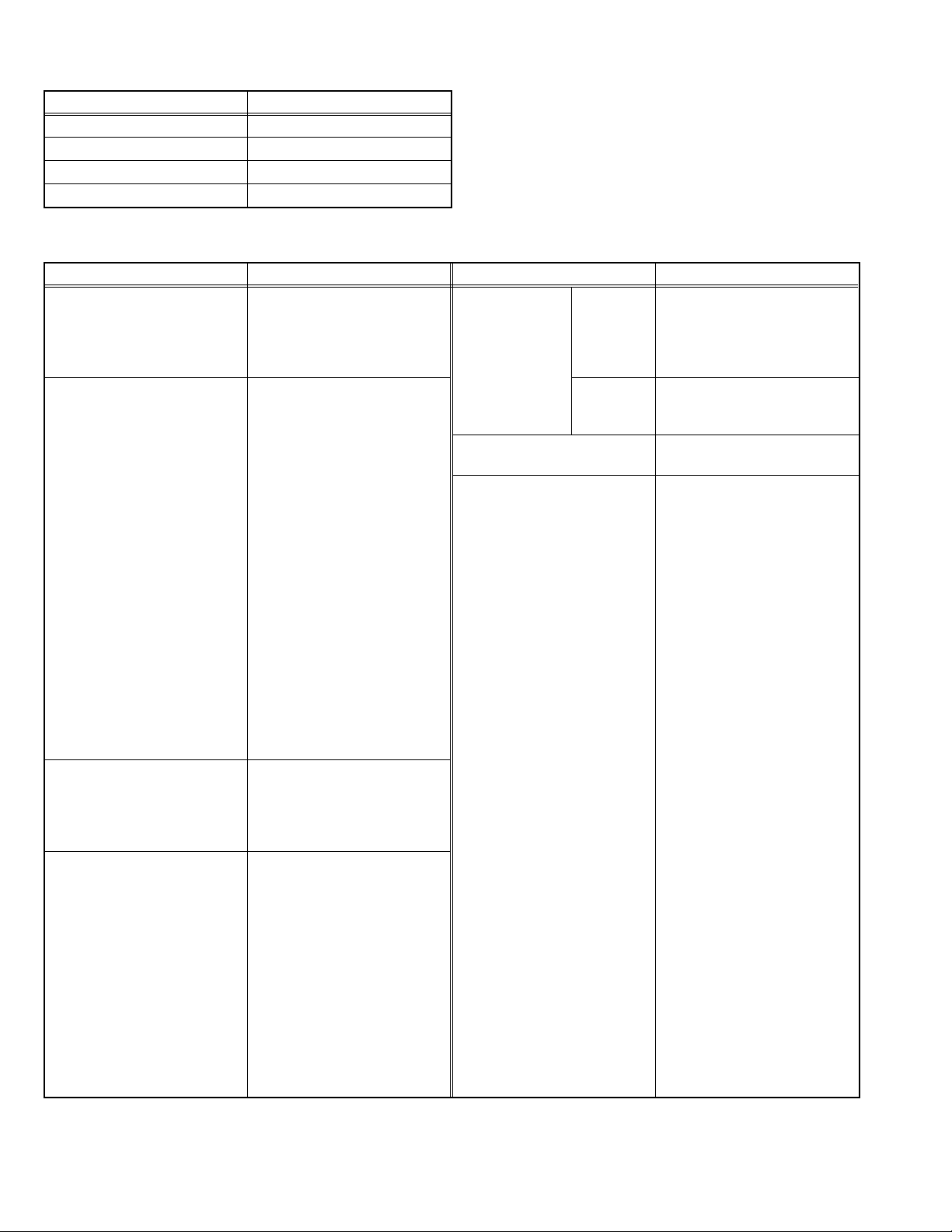
SPECIFICATION
Items Contents
Dimensions (W × H × D) 81.2cm × 58.5cm × 51.8cm
Mass 43.6kg
TV RF System B/G, I, D/K, K1, M
Colour System PAL / SECAM / NTSC 3.58 / NTSC 4.43
Stereo System A2 (B/G) / NICAM (B/G, I, D/K)
Receiving
Frequency
Intermediate
Frequency
Colour
Sub Carrier
Frequency
Aerial Input Terminal 75Ω unbalanced, coaxial
Power Input AC 110V~AC 240V , 50Hz/60Hz
Power Consumption Avg.132W
Picture Tube Visible size : 67.6cm (Diagonal) / 54.1cm × 40.6cm (H × V)
High Voltage 31.5kV +1.0kV / -1.5kV (At zero beam current)
Speaker 6.5cm × 13cm, Oval type × 2
Audio Power Output 10W + 10W
Video / Audio
Input
Component Video
Video / Audio
Output
Headphone 3.5mm stereo mini jack × 1
Remote Control Unit RM-C1352
Design & specifications are subject to change without notice.
VHF Low
VHF High
UHF
CATV
VIF
SIF
PAL
SECAM
NTSC
S-Video
[VIDEO-1]
Video
Audio(L/R)
[VIDEO-3]
Video
Audio(L/R)
46.25MHz ~168.25MHz
175.25MHz ~ 463.25MHz
471.25MHz ~ 863.25MHz
Mid : X-Z+2, S1~S10
Super : S11~S20
Hyper : S21~S41
38.0MHz
32.5MHz(5.5MHz) / 32.0MHz(6.0MHz) / 3.15MHz(6.5MHz) / 33.5MHz (4.5MHz)
4.43MHz
4.40625MHz / 4.25MHz
3.58MHz / 4.43MHz
Mini-DIN 4 pin connector × 1
Y : 1V(p-p), Positive (Negative sync provided), 75Ω
C : 0.286V(p-p) (burst signal), 75Ω
1V(p-p), negative sync, 75Ω, RCA pin jack × 4
500mV(rms) (-4dBs), High impedance, RCA pin jack × 8
RCA pin jack × 3
Y : 1V(p-p), 75Ω
CB : 0.7V(p-p), 75Ω
CR : 0.7V(p-p), 75Ω
1V(p-p) 75Ω, RCA pin jack × 1
500mV(rms) (-4dBs), Low impedance, RCA pin jack × 2
(AA/R06/UM-3 battery × 2)
1-2 (No.52199)
Page 3

SECTION 1
PRECAUTION
1.1 SAFETY PRECAUTIONS
(1) The design of this product contains special hardware,
many circuits and components specially for safety
purposes. For continued protection, no changes should be
made to the original design unless authorized in writing by
the manufacturer. Replacement parts must be identical to
those used in the original circuits. Service should be
performed by qualified personnel only.
(2) Alterations of the design or circuitry of the products should
not be made. Any design alterations or additions will void
the manufacturer's warranty and will further relieve the
manufacturer of responsibility for personal injury or
property damage resulting therefrom.
(3) Many electrical and mechanical parts in the products have
special safety-related characteristics. These
characteristics are often not evident from visual inspection
nor can the protection afforded by them necessarily be
obtained by using replacement components rated for
higher voltage, wattage, etc. Replacement parts which
have these special safety characteristics are identified in
the parts list of Service manual. Electrical components
having such features are identified by shading on the
schematics and by ( ) on the parts list in Service
manual. The use of a substitute replacement which does
not have the same safety characteristics as the
recommended replacement part shown in the parts list of
Service manual may cause shock, fire, or other hazards.
(4) Don't short between the LIVE side ground and
ISOLATED (NEUTRAL) side ground or EARTH side
ground when repairing.
Some model's power circuit is partly different in the GND.
The difference of the GND is shown by the LIVE : ( ) side
GND, the ISOLATED (NEUTRAL) : ( ) side GND and
EARTH : ( ) side GND.
Don't short between the LIVE side GND and ISOLATED
(NEUTRAL) side GND or EARTH side GND and never
measure the LIVE side GND and ISOLATED (NEUTRAL)
side GND or EARTH side GND at the same time with a
measuring apparatus (oscilloscope etc.). If above note will
not be kept, a fuse or any parts will be broken.
(5) If any repair has been made to the chassis, it is
recommended that the B1 setting should be checked or
adjusted (See B1 POWER SUPPLY check).
(6) The high voltage appli ed to the picture tube must confo rm
with that specified in Service manual. Excessive high
voltage can cause an increase in X-Ray emission, arcing
and possible component damage, therefore operation
under excessive high voltage conditions should be kept to
a minimum, or should be prevented. If severe arcing
occurs, remove the AC power immediately and determine
the cause by visual inspection (incorrect installation,
cracked or melted high voltage harness, poor soldering,
etc.). To maintain the proper minimum level of soft X-Ray
emission, components in the high voltage circuitry
including the picture tube must be the exact replacements
or alternatives approved by the manufacturer of the
complete product.
(7) Do not check high voltage by d rawing an arc. Use a high
voltage meter or a high voltage probe with a VTVM.
Discharge the picture tube before attempting meter
connection, by connecting a clip lead to the gr ound frame
and connecting the other end of the lead through a 10kΩ
2W resistor to the anode button.
(8) When service is required, obse rve the original lead dress.
Extra precaution should be given to assure correct lead
dress in the high voltage circuit area. Where a short circuit
has occurred, those components that indicate evidence of
overheating should be replaced. Always use the
manufacturer's replacement components.
(9) Isolation Check (Safety for Electrical Shock Hazard)
After re-assembling the product, always perform an
isolation check on the exposed metal parts of the cabinet
(antenna terminals, video/audio input and output terminals,
Control knobs, metal cabinet, screw heads, earphone jack,
control shafts, etc.) to be sure the product is safe to operate
without danger of electrical shock.
a) Dielectric Strength Test
The isolation between the AC primary circuit and all metal
parts exposed to the user, particularly any exposed metal
part having a return path to the chassis should withstand a
voltage of 3000V AC (r.m.s.) for a period of one second. (.
. . . Withstand a voltage of 1100V AC (r.m.s.) to an
appliance rated up to 120V, and 3000V AC (r.m.s.) to an
appliance rated 200V or more, for a period of one second.)
This method of test requires a test equipment not generally
found in the service trade.
b) Leakage Current Chec k
Plug the AC line cord directly into the AC outlet (do not use
a line isolation transformer during this check.). Using a
"Leakage Current Tester", measure the leakage current
from each exposed metal part of the cabinet, particularly
any exposed metal part having a return path to the chassis,
to a known good earth ground (water pipe, etc.). Any
leakage current must not exceed 0.5mA AC (r.m.s.).
However, in tropical area, this must not exceed 0.2mA AC
(r.m.s.).
Alternate Check Method
Plug the AC line cord directly into the AC outlet (do not
use a line isolation transformer during this check.). Use
an AC voltmeter having 1000Ω per volt or more
sensitivity in the following manner. Connect a 1500Ω
10W resistor paralleled by a 0.15µF AC-type capacitor
between an exposed metal part and a known good earth
ground (water pipe, etc.). Measure the AC voltage
across the resistor with the AC voltmeter. Move the
resistor connection to each exposed metal part,
particularly any exposed metal part having a return path
to the chassis, and measure the AC voltage ac ross the
resistor. Now, reverse the plug in the AC outlet and
repeat each measurement. Any voltage measured must
not exceed 0.75V AC (r.m.s.). This corresponds to
0.5mA AC (r.m.s.).
However, in tropical area, this must not exceed 0.3V AC
(r.m.s.). This corresponds to 0.2mA AC (r.m.s.).
AC VOLTMETER
(HAVING 1000 /V,
OR MORE SENSITIVITY)
0.15 F AC-TYPE
PLACE THIS PROBE
1500 10W
GOOD EARTH GROUND
ON EACH EXPOSED
METAL PART
(No.52199)1-3
Page 4
SECTION 2
SPECIFIC SERVICE INSTRUCTIONS
2.1 FEATURES
• New chassis design enable use of an interactive on-screen control.
• Pure FLAT CRT reproduce fine textured.
• Digi Pure pro : Auto digi pure with motion picture compensation.
• Because this TV unit corresponds to multiplex broadcast, users can enjoy music programs and sporting events with live realism.
In addition, BILINGUAL programs can be heard in their original language.
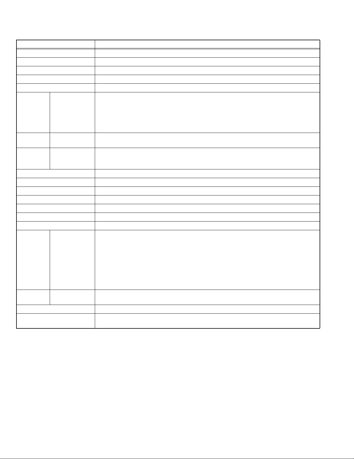
2.2 FUNCTIONS
FRONT TERMINAL & CONTROL
S
1 2 3 4 5 6 7 8 9
1
HEADPHONE jack
2
VIDEO-4 terminal (S-VIDEO / VIDEO / L/MONO / R)
3
MENU/OK button
4
CHANNEL -/+ (MENU UP/DOWN) button
5
VOLUME -/+ (MENU LEFT/RIGHT) button
REAR TERMINAL
OVER
V
IN (VIDEO-4)
L/MONO
R
MENU
OK
CHANNEL
VOLUME
TV/VIDEO
EXIT
6
TV / VIDEO / EXIT button
7
Remote Control sensor
8
POWER lamp
9
POWER button
POWER
1 2 3 4
1-4 (No.52199)
1
VIDEO-1 (INPUT) terminal
R
R
R
AUDIO
L/MONO
C
R
AUDIO
L/MONO
AUDIO
VIDEO
B
L
VIDEO
S
OVER
Y/VIDEOC
VIDEO-1
VIDEO-2
VIDEO-3/
COMPONENT
OUTPUT
(S, VIDEO, L/MONO ,R)
2
VIDEO-2 (INPUT) terminal
( VIDEO, L/MONO ,R)
3
VIDEO-3 (INPUT) terminal
(Y/VIDEO, C
4
OUTPUT (VIDEO, AUDIO L/R) terminal
B,CR , L/MONO, R) /COMPONENT
(VIDEO, L, R)
5
AERIAL socket
5
Page 5
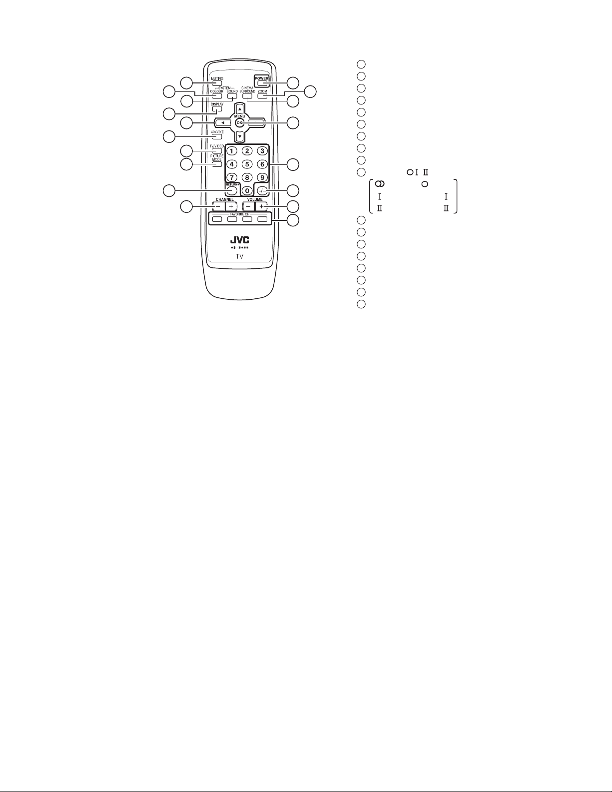
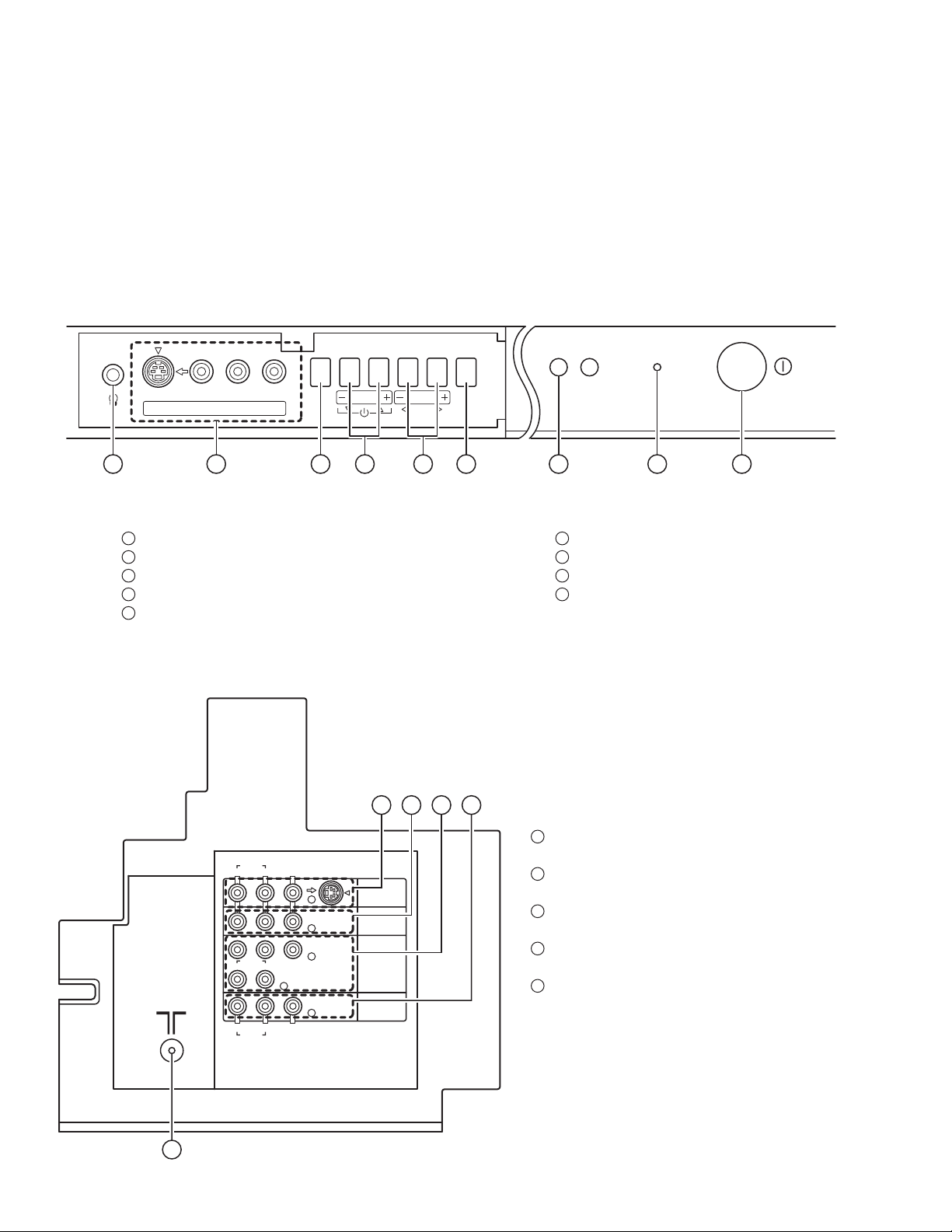
REMOTE CONTROL UNIT
5
7
10
13
11
12
17
1
POWER key
2
4
1
2
6
8
3
9
14
15
16
18
ZOOM key
3
CINEMA SURROUND key
4
MUTING key
5
COLOUR SYSTEM key
6
SOUND SYSTEM key
7
DISPLAY key
8
MENU (/&/) keys
9
MENU / OK key
10
STEREO / key
ޓޓ:Stereo / :Mono
:Bilingual (sub )
:Bilingual (sub )
11
TV / VIDEO key
12
PICTURE MODE key
13
RETURN + key
14
CHANNEL keys
15
-/-- Key
16
VOLUME +/- keys
17
CHANNEL +/- keys
18
FAVORITE CH keys
(No.52199)1-5
Page 6
SECTION 3
DISASSEMBLY
3.1 DISASSEMBLY PROCEDURE
3.1.1 REMOVING THE REAR COVER
(1) Unplug the power cord.
(2) Remove the 16 screws [A] as shown in the Fig. 1.
(3) Withdraw the REAR COVER toward you.
3.1.2 REMOVING THE AV TERMINAL BOARD
• Remove the REAR COVER.
(1) Remove the 5 screws [B] as shown in the Fig. 1.
(2) Withdraw the AV TERMINAL BOARD toward you.
3.1.3 REMOVING THE CHASSIS
• Remove the REAR COVER.
(1) Slightly raise the both sides of the CHASSIS by hand and
remove the 2 claws under the both sides of the CHASSIS
from the front cabinet.
(2) Withdraw the CHASSIS backward.
(If necessary, take off the wire clamp, connectors etc.)
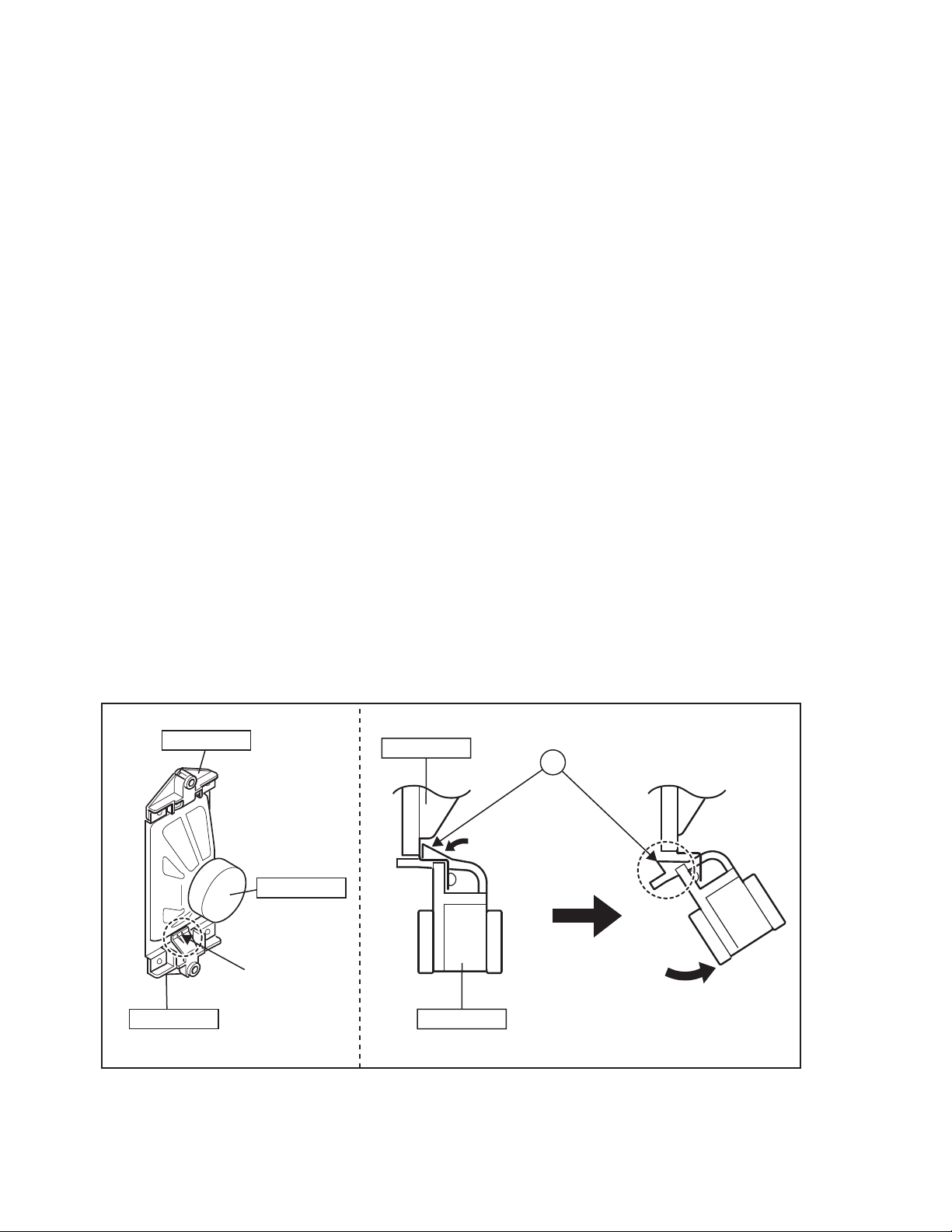
3.1.4 REMOVING THE SPEAKER
• Remove the REAR COVER.
(1) Remove the 2 screws [C], and remove the SP HOLDER as
shown in Fig. 1.
NOTE :
When removing the screws [C] of the SP HOLDER,
remove the lower side screw first, and then remove the
upper one.
(2) Remove the claw [D] push the SP HOLDER as shown in
Fig. 2.
(3) Follow the same steps when removing the other
SPEAKER.
3.1.5 CHECKING THE PW BOARD
• To check the back side of the PW Board.
(1) Pull out the CHASSIS. (Refer to REMOVING THE
CHASSIS).
(2) Erect the CHASSIS vertically so that you can easily check
the back side of the PW Board.
3.1.6 CAUTION
• When erecting the CHASSIS, be careful so that there will be
no contacting with other PW Board.
• Before turning on power, make sure that the wire connector is
properly connected.
• When conducting a check with power supplied, be sure to
confirm that the CRT EARTH WIRE (BRAIDED ASS'Y) is
connected to the CRT SOCKET PW board.
3.1.7 WIRE CLAMPING AND CABLE TYING
(1) Be sure to clamp the wire.
(2) Never remove the cable tie used for tying the wires togeth-
er.
Should it be inadvertently removed, be sue to tie the wires
with a new cable tie.
SP HOLDER
SPEAKER
CLAW
SP HOLDER SP HOLDER
SPEAKER
Fig.2
D
[SIDE VIEW]
1-6 (No.52199)
Page 7
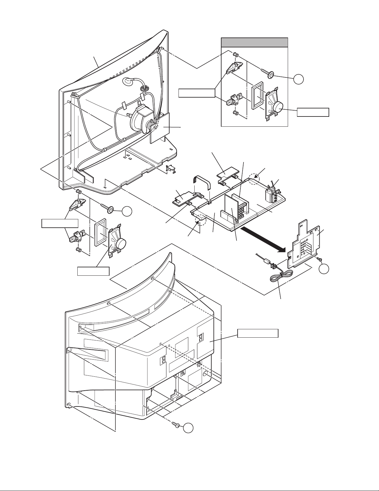
FRONT CABINET
See Fig. 2
C
(X2)
SP HOLDER
SPEAKER
CRT SOCKET
PWB
SP HOLDER
SPEAKER
FRONT CONTROL
PWB (1/2)
C
(X2)
CONTROL
BASE
FRONT CONTROL
PWB (2/2)
CLAW
MAIN PWB
MICOM / 100Hz
PWB
CLAW
FBT
POWER & DEF.
PWB
AV
TERMINAL
BOARD
AV SW
PWB
B
(X5)
POWER CORD
A
REAR COVER
(X16)
Fig.1
(No.52199)1-7
Page 8
3.2 MEMORY IC REPLACEMENT
3.2.1 MEMORY IC
This TV use memory IC.
In the memory IC, there are memorized data for correctly
operating the video and deflection circuits.
When replacing memory IC, be sure to use IC written with the
initial values of data.
3.2.2 PROCEDURE FOR REPLACING MEMORY IC
(1) Power off
Switch the power off and disconnect the power cord from
the wall outlet.
(2) Replace the memory IC
Be sure to use a memory IC written with the initial da ta
values.
(3) Power on
Connect the power plug into the wall outlet and switch the
power on.
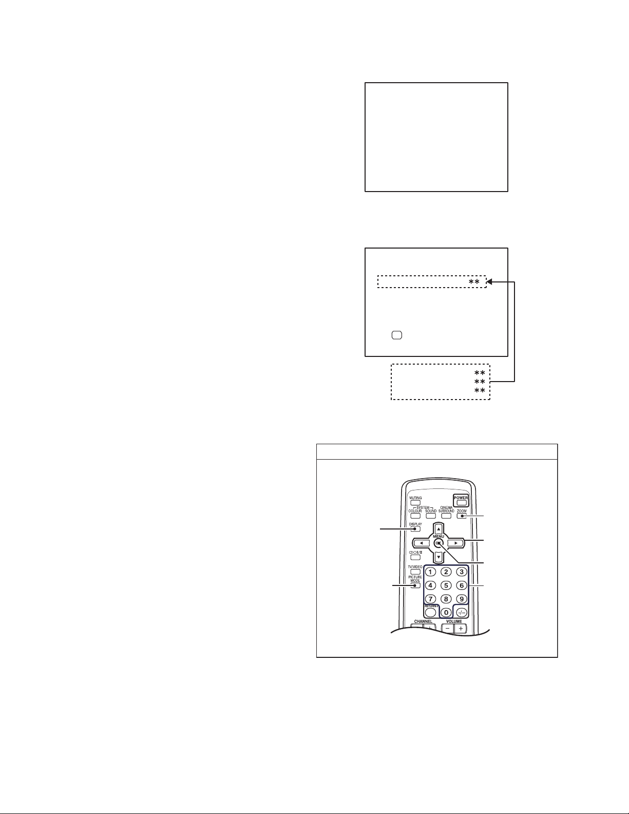
(4) Check and setting of SYSTEM CONSTANT SET
• It must not adjust without signal.
a) Press the [DISPLAY] key and the [PICTURE MODE]
key of the REMOTE CONTROL UNIT
simultaneously.
b) The SERVICE MENU screen of Fig. 1 will be
displayed.
c) While the SERVICE MENU is displayed , press the
[DISPLAY] key and [PICTURE MODE] key
simultaneously, and the SYSTEM CONSTANT SET
screen of Fig. 2 will be displayed.
d) Check the setting values of the SYSTEM
CONSTANT SETTING. If the value is different, select
the setting item with the [MENU /] key, and set
the correct value with the [MENU /] key.
e) Press the [OK] key to memorize the setting value.
f) Press the [DISPLAY] key, and return to the normal
screen.
(5) Receive channels setting
Refer to the OPERATING INSTRUCTIONS and set the
receive channels (channels preset) as described.
(6) User settings
Check the user setting values and if setting value is
different, set the correct value. For setting, refer to the
OPERATING INSTRUCTIONS.
(7) Setting of SERVICE MENU
Verify the setting items of the SERVICE MENU, and reset
where necessary. For setting, refer to the SERVICE
ADJUSTMENTS.
DISPLAY key
SERVICE MENU
1. IF
3. AUDIO
5. VSM PRESET
7.
9. SHIPPING(OFF)
1-9 : SELECT DISP : EXIT
2. V/C
4. DEF
6. STATUS
8. SURROUND
0. BUS FREE
Fig.1
SYSTEM CONSTANT SET
1. TEXT
OK
2. PIP
3. COLOUR AUTO
4. BLUE BACK MUTE
DISP : EXIT-/+ : STORE
Fig.2
SERVICE MENU
ZOOM
(ASPECT) key
MENU key
(/ & /)
OK key
1-8 (No.52199)
PICTURE MODE
key
SETTING ITEM
SELECT key
(Numbers key)
Fig.3
Page 9
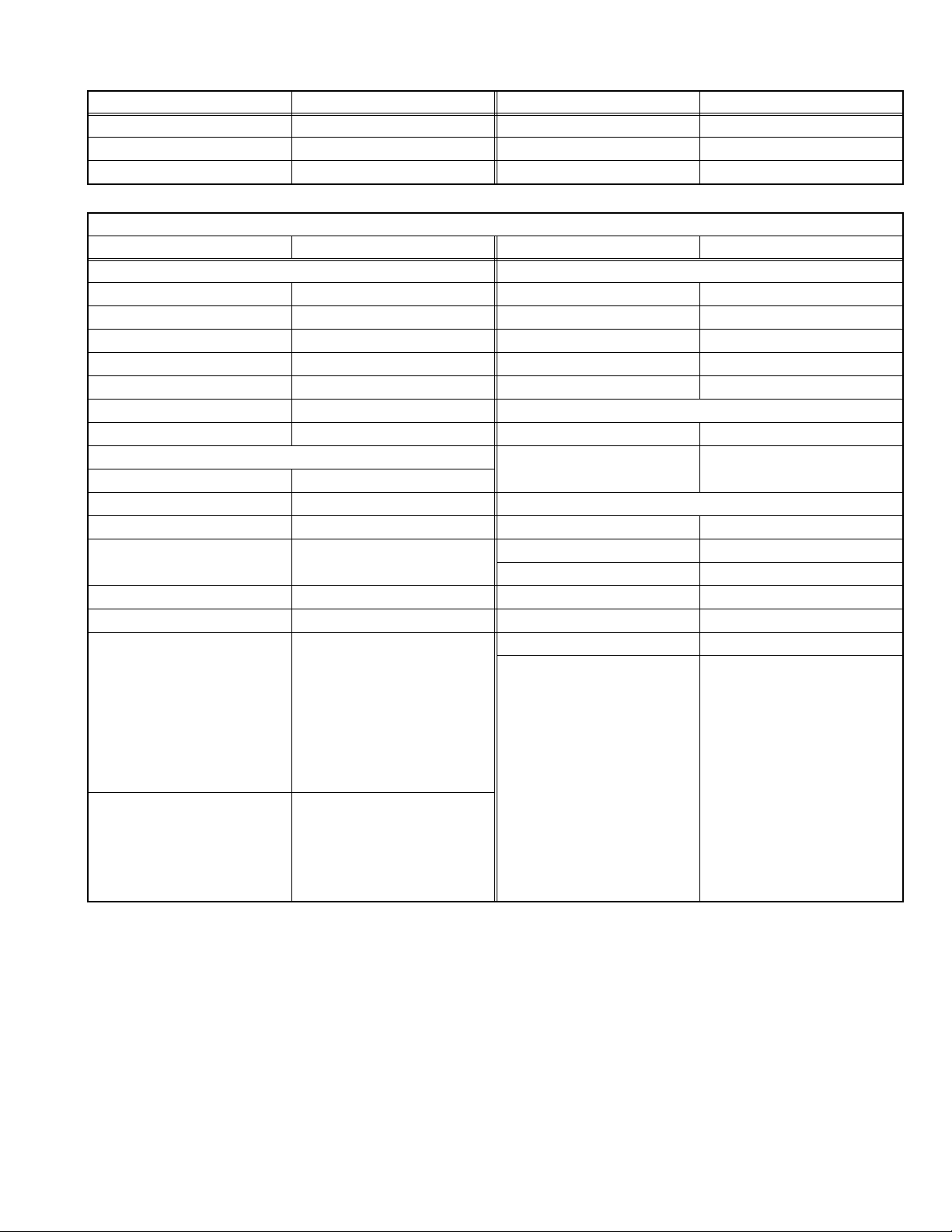
3.2.3 FACTORY SETTING VALUES
Setting item Setting value Setting item Setting value
MAIN POWER SW OFF SUB POWER SW ON
CHANNEL PR1 DISPLAY INDICATED
PRESET CHANNEL
Setting item Setting value Setting item Setting value
PICTURE SETTING SOUND
PICTURE MODE BRIGHT BASS Center
CONTRAST Center TREBLE Center
BRIGHT Center BALANCE Center
SHARP Center CINEMA SURROUND OFF
COLOUR Center AI VOLUME ON
WHITE BALANCE MID INSTALL
AI ECO SENSOR DISPLAY OFF LANGUAGE ENGLISH
PICTURE FEATURES EDIT PRESET CHANNEL ONLY
DIGITAL VNR AUTO
Digi Pure AUTO FEATURES
PULL DOWN AUTO SLEEP TIMER OFF
COLOUR SYSTEM TV : Depends on PR/CH
ZOOM REGULAR CHANNEL GUARD ALL CH : OFF
PICTURE TILT Center AUTO SHUT OFF OFF
FAVORITE CH SETTING PRO1 : RED
VIDEO SETTING VIDEO STATAS : VIDEO1
See OPERATING INSTRUCTIONS.
MENU SETTING
EXT : AUTO
PRO2 : GREEN
PRO3 : YELLOW
PRO4 : BLUE
PICTIRE MODE : BRIGHT
DIGITAL VNR : AUTO
WHITE BALANCE : MID
Digi Pure : AUTO
PICTURE EFFRCT : OFF
PICTURE MODE : BRIGHT
DIGITAL VNR: AUTO
WHITE BALANCE : MID
Digi Pure : AUTO
PICTURE EFFECT : OFF
VOLUME 10
OTHER : NON (SPACE)
BLUE BACK ON
CHILD LOCK OFF (for all the channels)
VIDEO-3 SETTING COMPONENT
(No.52199)1-9
Page 10
3.2.4 SYSTEM CONSTANT SETTING
Setting item Setting value
1. TEXT NO
2. PIP NO
3. COLOUR AUTO NO
4. BLUE BACK MUTE NO
3.2.5 SERVICE MENU SETTING ITEMS
Setting item Setting value Setting item Setting value
1. IF 1. VCO 5. VSM PRESET BRIGHT
STANDARD
SOFT
2. V / C 1. RGB BLK
2. CUTOFF R
3. CUTOFF G
4. CUTOFF B
5. WDR R
6. WDR G
7. WDR B
8. BRIGHT
9. CONTRAST
10. COLOUR
11. HUE
12. SHARP
13. SC ADJ.
14. TOP BLK
15. BTM BLK
16. YUV BRIGHT
17. YUV CONT
18. YUV COLU
19. YUV COLV
20. YUV YDEL
21. YUV UVDEL
22. YCDELM
3. AUDIO 1. ERR LIMIT
2. A2 ID THR
3. SYSTEM
4. SUB BASS
5. SUB TREBLE
4. DEF 1. V-SHIFT
2. V-SIZE
3. H-CENT
4. H-SIZE
5. TRAPEZ
6. EW-PIN
7. COR-UP
8. COR-LO
9. COR-UP-S
10. COR-LO-S
11. HUE
12. BOW
13. V-S.CR
14. V-LIN
6. STATUS
(Do not adjust)
8. SURROUND 1. CH CONFIG
COOL
WARM
NORMAL
1. CONT
2. BRIGHT
3. SHARP
4. COLOUR
5. TINT
6. WDR R
7. WDR G
8. WDR B (Do not adjust)
1. SOFT
2. MATRIX
3. REPRODUCT
4. CENTER MODE
5. SPATIAL EFF
6. VIRTUAL EFF
7. BASS EFFECT
8. HARM
9. HPF
10. LPF
11. AMP LIMIT
12. LEVEL ADJ
13. SWC
14. SW HPF
15. VOLUME
16. HYPER EFF
17. EFFECT MOD
18. HP GAIN
1-10 (No.52199)
Page 11

3.3 REPLACEMENT OF CHIP COMPONENT
3.3.1 CAUTIONS
(1) Avoid heating for more than 3 seconds.
(2) Do not rub the electrodes and th e resist parts of the pattern.
(3) When removing a chip part, melt the solder adequately.
(4) Do not reuse a chip part after removing it.
3.3.2 SOLDERING IRON
(1) Use a high insulation soldering iron with a thin pointed end of it.
(2) A 30w soldering iron is recommended for easil y removing parts.
3.3.3 REPLACEMENT STEPS
1. How to remove Chip parts
2. How to install Chip parts
[Resistors, capacitors, etc.]
(1) As shown in the figu re, push the part with tweezers and
alternately melt the solder at each end.
(2) Shift with the tweezers and remove the chip part.
[Transistors, diodes, variable resistors, etc.]
(1) Apply extra solder to each lead.
SOLDER
SOLDER
[Resistors, capacitors, etc.]
(1) Apply solder to the pattern as indicated in the figure.
(2) Grasp the chip part with tweezers and place it on the
solder. Then heat and melt the solder at both ends of the
chip part.
[Transistors, diodes, variable resistors, etc.]
(1) Apply solder to the pattern as indicated in the figure.
(2) Grasp the chip part with tweezers and place it on the
solder.
(3) First solder lead A as indicated in the figure.
(2) As shown in the figu re, push the part with tweezers and
alternately melt the solder at each lead. Shift and remove
the chip part.
NOTE :
After removing the part, remove remaining solder from the
pattern.
A
B
C
(4) Then solder leads B and C.
A
B
C
(No.52199)1-11
Page 12

SECTION 4
ADJUSTMENT
4.1 ADJUSTMENT PREPARATION
(1) There are 2 ways of adjusting this TV : One is with the REMOTE C ONTROL UNIT and the other i s the conventional method
using adjustment parts and components.
(2) The adjustment using the REMOTE CONTROL UNIT is made on the basis of the initial setting values. The setting values which
adjust the screen to the optimum condition can be different from the initial setting values.
(3) Make sure that connection is correctly made AC to AC power source.
(4) Turn on the power of the TV and measuring instruments for warning up for at least 30 minutes before starting adjustments.
(5) If the receive or input signal is not specified, use the most appropriate signal for adjustment.
(6) Never touch the parts (such as variable resistors, transformers and condensers) not shown in the adjustment items of this service
adjustment.
(7) Preparation for adjustment.
Unless otherwise specified in the adjustment items, preset the following functions with the REMOTE CONTROL UNIT.
Item Preset value
PICTURE MODE (VSM) STANDARD
WHITE BALANCE MID
DIGITAL VNR AUTO
Digi Pure AUTO
BASS / TREBLE / BALANCE Center
CINEMA SURROUND OFF
ZOOM REGULAR
SLEEP TIMER OFF
4.2 MEASURING INSTRUMENT AND FIXTURES
(1) DC voltmeter (or digital voltmeter)
(2) HV voltmeter
(3) Oscilloscope
(4) Signal generator (Pattern generator : PAL / SECAM / NTSC)
(5) Remote control unit
4.3 ADJUSTMENT ITEMS CHECK ITEMS
• B1 POWER SUPPLY check
• HIGH VOLTAGE check
TUNER / IF CURCUIT
• IF VCO check
FOCUS
• FOCUS adjustment
VSM PRESET SETTING
• VSM PRESET
VIDEO CIRCUIT
• WHITE BALANCE adjustment
• SUB BRIGHT adjustment
• SUB CONTRAST adjustment
• SUB COLOUR-1 adjustment
• SUB COLOUR-2 adjustment
• SUB HUE-1 adjustment
• SUB HUE-2 adjustment
• COLOUR DECODER VCO adjustment
DEFLECTION CIRCUIT
• V. POSITION adjustment
• V. SIZE adjustment
• H. POSITION adjustment
• H. SIZE adjustment
• SIDE-PIN adjustment
• TRAPEZIUM adjustment
• UPPER / LOWER CORNER PIN adjustment
• PARALLEL(TILT) adjustment
• BOW adjustment
• V. S-SHAPE CORRECTION & LINEARITY adjustment
AUDIO CIRCUIT
1-12 (No.52199)
Page 13

4.4 ADJUSTMENT LOCATION
FRONT CONTROL PWB(1/2) FRONT CONTROL PWB(2/2)
FRONT
POWER CORD
POWER
F901
C901
PW
W
LF901
MAIN PWB
IC101
J
CN00B
TV/VIDEO EXIT
VOL +
VOL -
MENU / OK
CH -
CH +
J
POWER &DEF PWB
AUDIO
R L/MONO
R4 L4 V4
IN (VIDEO-4)
VIDEO
S-VIDEO
S IN
F
HEAD
POHONE
SP
SP-R
SP-L
FRONT
TUNER
B
F
AV SW PWB
CN001
ANT- IN
RT
MICOM / 100Hz
PWB
A
MEMORY IC
IC701
IC001
MICON
R
CN002
C1
CRT SOCKET PWB
CN003
CN004
CN005
W
CRT
BRAIDED WIRE
DEG
DEG COIL
DY
FBT
HV
G
X
1
1pin:B1(TP-91)
5
2pin:NC
3pin:X-RAY
4pin:X-RAY
5pin:GND( )
CN00R
TP-E
TP-47B
VM
CN00G
TP-Y
CRT
FRONT TOP
YHC
(VR2)
XV COIL
YV
(VR1)
PC MAGNET
(SOLDER SIDE)
H
V
FOCUS 2 VR
FOCUS 1 VR
SCREEN VR
(No.52199)1-13
Page 14

4.5 BASIC OPERATION OF SERVICE MENU
4.5.1 TOOL OF SERVICE MENU OPERATION
Operate the SERVICE MENU with the REMOTE CONTROL UNIT.
4.5.2 SERVICE MENU ITEMS
With the SERVICE MENU, various adjustments can be made, and they are broadly classified in the following items of settings.
1.IF This mode adjusts the setting values of the IF circuit.
2.V/C This mode adjusts the setting values of the VIDEO circuit.
3.AUDIO This mode adjusts the setting values of the multiplicity AUDIO circuit.
4.DEF This mode adjusts the setting values of the DEFLECTION circuit for each aspect mode given below.
5.VSM PRESET This mode adjusts the initial setting values of BRIGHT, STANDARD and SOFT. (VSM : Video Status Memory)
6.STATUS It is no requirement to adjustment. [Do not adjust]
8.SURROUND This mode adjusts the setting values of the SURROUND circuit.
9.SHIPPING (OFF) This mode adjusts the setting values of the channel presettings.
If you turn the SHIPPING position set ON.
This setting becomes channel presetting automatically.
Also you turn the TV power off, this setting become OFF position automatically.
0.BUS FREE It is not requirement to adjustment.
4.5.3 BASIC OPERATION OF SERVICE MENU
1. HOW TO ENTER THE SERVICE MENU
Press the [PICTURE MODE] key and the [DISPLAY] key of the
REMOTE CONTROL UNIT simultaneously, and the SERVICE
MENU screen of Fig. 1 will be displayed.
2. SELECTION OF SUB MENU SCREEN
Press one of [1] ~ [0] keys of the REMOTE CONTROL UNIT
and select the SERVICE MENU SCREEN (See Fig. 3), form
1. IF
3. AUDIO
5. VSM PRESET
7.
9. SHIPPING(OFF)
1-9 : SELECT DISP : EXIT
SERVICE MENU
2. V/C
4. DEF
6. STATUS
8. SURROUND
0. BUS FREE
the SERVICE MENU.
Fig.1
1. IF
2. V/C
3. AUDIO
4. DEF
SERVICE MENU
5. VSM PRESET
6. STATUS [Do not adjust]
7. PIP [HV-29WH51/S, HV-29WH71/G only]
8. SURROUND
9. SHIPPING(OFF)
0. BUS FREE
DISPLAY key
ZOOM
(ASPECT) key
MENU key
(/ & /)
OK key
1-14 (No.52199)
PICTURE MODE
key
Numbers keys
[RM-C1350]
Fig.2
Page 15

3. SETTING METHOD
1.IF
[1. VCO] : It must not adjust without signal
(1) [1] key
Select 1.IF.
(2) [1] key
Select 1.VCO(CW).
Check the arrow position between the ABOVE REF. and BELOW REF.
(3) [DISPLAY] key
Return to the SERVICE MENU screen.
2.V/C, 3.AUDIO, 4.DEF, 5.VSM PRESET, 7.PIP AND 8.SURROUND.
(1) [2], [3], [4], [5], [7], [8] key
Select one from 2.V/C, 3.AUDIO, 4.DEF, 5.VSM PRESET, 8.SURROUND.
(2) [MENU /] key
Select setting items.
(3) [MENU /] key
Set (adjust) the setting values of the setting items.
(4) MENU [OK] key
Memorize the setting value.
(Before storing the setting values in memory, do not press the CH, TV, POWER ON / OFF key. if you do, the values will not
be stored in memory.)
(5) [DISPLAY] key
Return to the SERVICE MENU screen.
6.STATUS, 9. SHIPPING(OFF) AND 0. BUS FREE.
It is not requirement to adjustment.
4. RELEASE OF SERVICE MENU
After completing the setting, return to the SERVICE MENU, then again press the [DISPLAY] key.
(No.52199)1-15
Page 16

4.5.4 SERVICE MENU FLOW CHART
SERVICE MENU
SERVICE MENU
1. IF
3. AUDIO
5. VSM PRESET
7.
9. SHIPPING(OFF)
1-9 : SELECT DISP : EXIT
2. V/C
4. DEF
6. STATUS
8. SURROUND
0. BUS FREE
1. V-SHIFT
2. V-SIZE
3. H-CENT
4. H-SIZE
5. TRAPEZ
6. EW-PIN
7. COR-UP
COLOUR TEMP
COOL
WARM
NORMAL
1. CH CONFIG
2. MATRIX
3. REPRODUCT
4. CENTER MODE
5. SPATIAL EFF
6. VIRTUAL EFF
7. BASS EFFECT
8. HARM
9. HPF
10. LPF
11. AMP LIMIT
12. LEVEL ADJ
13. SWC
14. SW HPF
15. VOLUME
16. HYPER EFF
17. EFFECT MOD
18. HP GAIN
8. COR-LO
9. COR-UP-S
10. COR-LO-S
11. HUE
12. BOW
13. V-S.CR
14. V-LIN
PICTURE MODE
BRIGHT
STANDARD
SOFT
1. CONT
2. BRIGHT
3. SHARP
4. COLOUR
5. TINT
6. WDR R
7. WDR G
8. WDR B
4. DEF
DEF REGULAR Hz
1. V-SHIFT
OK
( )
DISP : EXIT-/+ : STORE
5. VSM PRESET
VSM PRESET STD
1. CONT
OK
DISP : EXIT-/+ : STORE
6. STATUS [Do not adjust]
STATUS
1. SOFT
OK
DISP : EXIT-/+ : STORE
8. SURROUND
SURROUND SOUND SYSTEM
1. CH CONFIG
OK
DISP : EXIT-/+ : STORE
Fig.3
1. IF (CW)
IF SERVICE MENU
1. VCO
DISP : EXIT1-2 : SELECT
VCO(CW)
TOO HIGH
ABOVE REF
JUST REF
BELOW REF
TOO LOW
,
DISP : EXIT
MHz
2. V/C
V/C PAL
1. RGB_BLK
OK
DISP : EXIT-/+ : STORE
3. AUDIO [Do not adjust]
AUDIO
1. ERR LIMIT
EEROR_RATE=
OK
DISP : EXIT-/+ : STORE
1. RGB BLK
2. CUTOFF R
3. CUTOFF G
4. CUTOFF B
5. WDR R
6. WDR G
7. WDR B
8. BRIGHT
9. CONTRAST
10. COLOUR
11. HUE
1. ERR LIMIT
2. A2 ID THR
3. SYSTEM
4. SUB BASS
5. SUB TREBLE
12. SHARP
13. SC ADJ.
14. TOP BLK
15. BTM BLK
16. YUV BRIGHT
17. YUV CONT
18. YUV COLU
19. YUV COLV
20. YUV YDEL
21. YUV UVDEL
22. YCDELM
1-16 (No.52199)
Page 17

4.6 INITIAL SETTING VALUE OF SERVICE MENU
(1) Adjustment of the SERVICE MENU is made on the basis of the initial setting val ues:however, the new setting values which set
the screen in its optimum condition may differ from the initial setting value.
(2) Do not change the initial setting values of the setting items not listed in "ADJUSTMENT PROCEDURE".
(3) "---" is impossible to adjust.
[2. V/C]
Initial setting value
Setting item Variable range
1. RGB BLK --- --- --- --- --- --- --- ---
2. CUTOFF R 0000~0255 150 150 150 150 5 5 0
3. CUTOFF G 0000~0255 150 150 150 150 -8 -8 0
4. CUTOFF B 0000~0255 150 150 150 150 0 0 0
5. WDR R 0000~0255 150 150 150 150 0 0 0
6. WDR G 0000~0255 150 150 150 150 0 0 0
7. WDR B 0000~0255 150 150 150 150 0 0 0
8. BRIGHT RF -128~0127 -25 -25 -25 -25 --- --- --VIDEO +6 +6 +6 +6 +2 +2 -4
9. CONTRAST RF 0000~0063 50 50 50 50 --- --- --VIDEO -5 -5 -5 -5 --- --- ---
10. COLOUR RF 0000~0063 36 55 25 5 --- --- --VIDEO -9 -5 -5 -2 -16 -7 3
11. HUE RF -064~0063 --- --- 4 0 --- --- --VIDEO --- --- 0 0 --- --- ---
12. SHARP RF -015~0015 +2 +2 +2 +2 -2 -2 -2
VIDEO -2 -2 -2 -2 -2 -2 -2
13. SC ADJ 0000~0063 18 18 18 18 --- --- ---
14. TOP BLK 0000~0255 35 35 46 46 35 46 46
15. BTM BLK -127~0511 -15 -15 -37 -37 -15 -37 -37
16. YUV BRIGHT -064~0063 --- --- --- --- -4 -4 -4
17. YUV CONT 0000~0063 --- --- --- --- 55 55 55
18. YUV COLU 0000~0063 --- --- --- --- 57 60 10
19. YUV COLV 0000~0063 --- --- --- --- 60 55 0
20. YUV YDEL 0000~0127 --- --- --- --- 50 50 35
21. YUV UVDEL 0000~0127 --- --- --- --- 49 49 35
22. TCDELM RF 0000~0127 2 0 0 0 --- --- --VIDEO 0 0 0 0 --- --- ---
RF / Composite Video / S-Video Component video
PAL SECAM NTSC 3.58 NTSC 4.43 50Hz-i 60Hz-i 60Hz-p
Initial setting value
Setting item Variable range
8. BRIGHT RF -128~0127 0 0 0 0 0 0 0
VIEDO 0 0 0 0 0 0 0
9. CONTRAST RF 0000~0063 -7 -7 -7 -7 --- --- --VIDEO -7 -7 -7 -7 --- --- ---
10. COLOUR RF 0000~0063 0 0 0 0 --- --- --VIDEO 0 0 0 0 0 0 0
RF/ Composite Video / S-Video Component video
PAL SECAM NTSC 3.58 NTSC 4.43 50Hz-i 60Hz-i 60Hz-p
Compress (16:9)
(No.52199)1-17
Page 18

[3. AUDIO]
Setting item Variable range Initial setting value
1. ERR LIMIT 0000~00FF 0010
2. A2 ID THR 0000~00FF 0019
3. SYSTEM B/G→I→D/K→M ---
4. SUB BASS -003~0003 0001
5. SUB TREBLE -003~0003 0001
[4. DEFLECTION]
Initial setting value
Setting item Variable range
1. V-SHIFT -32~0031 +3 -2 0 0 0 0
2. V-SIZE -064~0063 -11 -1 0 0 -30 0
3. H-CENT -128~0127 -16 0 -2 0 0 0
4. H-SIZE -128~0127 +7 -1 0 0 0 0
5. TRAPEZ -063~0064 -2 0 0 0 +1 0
6. EW-PIN -128~0127 -17 -1 0 0 0 0
7. COR-UP -064~0064 +1 +16 0 0 0 0
8. COR-LO -064~006 4 +1 +6 0 0 0 0
9. COR-UP-S -064~0064 +1 -8 0 0 0 +5
10. COR-LO-S -064~0064 +1 0 0 0 0 0
11. HUE -128~0127000000
12. BOW -128~0127000000
13. V-S.CR -064~0063 +16 +5 0 0 0 0
14. V-LIN -064~0063 -1 0 0 0 0 0
REGULAR ZOOM 16:9
50Hz-i 60Hz-p 50Hz-i 60Hz-p 50Hz-i 60Hz-p
[5. VSM PRESET] [Do not adjust : All fixed]
Setting item Variable range
1. CONT -16~16 16 -2 0 --- --- ---
2. BRIGHT -16~16 -2 -2 0 --- --- ---
3. SHARP -16~16 0 -10 0 --- --- ---
4. COLOUR -16~16 0 -2 0 --- --- ---
5. TINT -16~16 0 0 0 --- --- ---
6. WDR R -16~16 --- --- --- -12 22 0
7. WDR G -16~16 --- --- --- -11 2 0
8. WDR B -16~16 --- --- --- 0 0 0
[8. SURROND]
Setting item Variable range
1. CH CONFIG 0000~0001 1 1
2. MATRIX 0000~0127 16 16
3. REPRODUCT 0000~0015 6 6
4. CENTER MODE 0000~0015 3 3
5. SPATIAL EFF 0000~0127 40 50
6. VIRTUAL EFF 0000~0127 35 47
7. BASS EFFECT 0000~0127 46 52
BRIGHT SOFT STANDARD COOL WARM NORMAL
Initial setting value
LOW HIGH
Initial setting value
1-18 (No.52199)
Page 19

Setting item Variable range
8. HARM 0000~0127 0 0
9. HPF 0002~0030 8 8
10. LPF 0005~0030 18 15
11. AMP LIMIT -032~00 00 -10 -15
12. LEVEL ADJ -128~0012 0 0
13. SWC 0005~0040 28 28
14. SW HPF 0000~0002 2 2
15. VOLUME 0000~0003 3 3
16. HYPER EFF 0000~0127 63 63
17. EFFECT MOD 0000~0002 0 0
18. HP GAIN 0000~0008 8 8
Initial setting value
LOW HIGH
(No.52199)1-19
Page 20

4.7 ADJUSTMENT PROCEDURE
4.7.1 CHECK ITEM
Item
B1 POWER
SUPPLY
check
Measuring
instrument
DC voltmeter
Remote
control unit
X connector
TP-91(B1)
TP-E( )
[POWER DEF
PWB]
HIGH VOLTAGE
HV voltmeter
CRT anode
check
Remote
Chassis GND
control unit
Test point Adjustment part Description
[2.V/C]
1.RGB BLK
(1) Receive a any broadcast.
(2) Press the [ZOOM] key and select the FULL mode.
(3) Select 2.V/C.
(4) Select < 1.RGB BLK >.
(5) Press the [MENU] key to find the cut off screen
(Black screen).
(6) Connect a DC voltmeter to TP-91(B1) and TP-E( ).
(7) Make sure that the voltage is DC139.9 ±2.0V.
(8) Press the [MENU] key to return to service menu.
[2.V/C]
1.RGB BLK
(1) Receive a any broadcast.
(2) Press the [ZOOM] key and select the FULL mode.
(3) Select 2.V/C.
(4) Select < 1. RGB BLK >.
(5) Press the [MENU] key to find the cut off screen
(Black screen).
(6) Connect a HV voltmeter to CRT anode and chassis
GND.
(7) Make sure that the voltage is DC31.5kV(+1kV,-
1.5kV).
(8) Press the [MENU] key to return to service menu.
NOTE:
• Remove the probe before removing the earth clip.
4.7.2 TUNER / IF CIRCUIT
Item
IF VCO
check
Measuring
instrument
Remote
control unit
1. VCO
TOO HIGH
ABOVE REF
JUST REF
BELOW REF
TOO LOW
Test point Adjustment part Description
IF SERVICE MENU
DISP : EXIT1-2 : SELECT
VCO(CW) , MHz
DISP : EXIT
[1.IF]
1.VCO
• Under normal conditions, no adjustment is required.
• Confirmation adjustment.
(1) Select 1.IF.
(2) Select < 1.VCO >
(3) Receive any broadcast.
(4) Check the arro w (←) position between the ABOVE
REF. and BELOW REF.
(5) Press the [OK] key and receiver any broadcast with
PIP button.
1-20 (No.52199)
Page 21

4.7.3 FOCUS
Item
Measuring
instrument
FOCUS Signal
generator
HVT
FOCUS 2 VR
FOCUS 1 VR
SCREEN VR
Test point Adjustment part Description
FOCUS1 VR
FOCUS2 VR
[In HVT]
(1) Receive a cross-hatch signal.
(2) Press the [ZOOM] key and select the REGULAR
mode.
(3) By turning the FOCUS 2 VR, adjust the to make the
vertical lines as fine and sharp as possible.
FOCUS 2 VRFOCUS 1 VR
1
2
123453
(4) By turning the FOCUS 2 VR, adjust the pictu re so
that the 5th vertical line from left side of the crosshatch picture becomes the thinnest.
(5) By turning the FOCUS 1 VR, adjust the 3rd
horizontal line from the upper side to become
uniform at the line center and its periphery.
(6) Carry out adjustment by repeating the steps 3, 4 and
5 about.
(7) Make sure that the lines remain in good focus, when
the screen is darkened.
4.7.4 VSM PRESET SETTING
Item
Measuring
instrument
VSM PRESET Remote
control unit
VSM preset
mode
BRIGHT
SOFT
STANDARD
VSM preset
mode
COOL
WARM
NORMAL
2.BRIGHT 3.SHARP
Inital setting value
COLOUR TEMP
7.WDR G
Test point Adjustment part Description
[5.VSM PRESET]
(BRIGHT/SOFT/
STANDARD)
1.CONT.
2.BRIGHT
3.SHARP
4.COLOUR
5.TINT
(COOL/WARM/
NORMAL)
6.WDR R
7.WDR G
8.WDR B
(1) Select 5.VSM PRESET.
(2) Select STD(Standard) with the [PICTURE MODE]
key of the remote control unit.
(3) Adjust the [MENU /] key to bring the set values
of < 1.CONT >~< 5.TINT > to the values shown in
the table.
(4) Press the [OK] key to memorize the set values.
(5) Respectively select the VSM PRESET mode for
BRIGHT and REGULAR, and make similar
adjustment as in 3 above.
(6) Press the [OK] key to memorize the set values.
(7) Select COOL of COLOUR TEMP with the [OK] key.
(8) Select 5.VSM PRESET.
(9) Adjust the [MENU /] key to bring the set values
Inital setting value
PICTURE MODE
4.COLOUR 5.TINT1.CONT.
-2 0 5 016
-2 -10 -2 0-2
00000
of < 6.WDR R > ~ < 8.WDR B > to the values shown
in the table.
(10) Press the [OK] key to memorize the set values.
(11) Respectively select NORMAL or WARM of
PICTURE MODE, and make similar adjustment as in
9 above.
(12) Press the [OK] key to memorize the set values.
NOTE:
8.WDR B6.WDR R
-11 0-12
2022
000
• Refer to OPERATING INSTRUCTIONS for the
PICTURE MODE.
(No.52199)1-21
Page 22

4.7.5 VIDEO CIRCUIT
The setting (adjustment) using the REMOTE CONTROL UNIT is made on the basis of the initial setting values.
The setting values which adjust the screen to the optimum condition can be different from the initial setting values.
Item
WHITE
BALANCE
SUB BRIGHT Remote
SUB
CONTRAST
SUB COLOUR-1 Remote
Measuring
instrument
Signal
generator
Remote
control unit
control unit
Remote
control unit
control unit
Test point Adjustment part Description
[2.V/C]
2.CUTOFF R
3.CUTOFF G
4.CUTOFF B
5.WDR R
6.WDR G
7.WDR B
(Do not move)
[2.V/C]
8.BRIGHT
[2.V/C]
9.CONTRAST
[2.V/C]
10.COLOUR
(PAL/SECAM/NTSC)
• Set the PICTURE MODE to NORMAL.
(1) Receive a black and white signal (colour off).
(2) Select 2.V/C .
(3)Select < 2.CUTOFF R >, < 3.CUTOFF G > and
< 4.CUTOFF B >.
(4) Adjust the screen until the black portion in the screen
becomes black.(Low light)
(5) Select < 5.WDR R > and < 6.WDR G >.
(6) Adjust the screen until the white portion in the screen
becomes white (High light).
NOTE:
• Do not adjust < 7.WDR B >.
(7) Press the [OK] key to memorize the set values.
(8) Change the contrast and brightness with the remote
control up & down from low-light to high-light and
check that the tracking of the white balance is good.
(1) Receive any broadcast.
(2) Select 2.V/C.
(3) Select < 8.BRIGHT >.
(4) Set the initial setting value of < 8.BRIGHT >.
(5) If the brightness is not the best with the initial setting
value, make fine adjustment until you get the best
brightness.
(6) Press the [OK] key to memorize the set values.
(1) Receive any broadcast.
(2) Select 2.V/C.
(3) Select < 9.CONTRAST >.
(4) Set the initial setting value of < 9.CONTRAST >.
(5) If the contrast is not the best with the initial setting
value, make fine adjustment until you get the best
contrast.
(6) Press the [OK] key to memorize the set values.
[Method of adjustment without measuring instrument]
PAL COLOUR :
(1) Receive PAL broadcast.
(2) Select 2.V/C.
(3) Select < 10.COLOUR >.
(4) Set the initial setting value for PAL COLOUR.
(5) If the colour is not the best with the initial set value,
make fine adjustment until you get the best colour.
(6) Press the [OK] key to memorize the set values.
SECAM COLOUR :
(1) Receive a SECAM broadcast.
(2) Make fine adjustment o f SECAM COLOUR in the
same manner as for above.
NTSC 3.58 COLOUR :
(1) Input a NTSC 3.58MHz COMPOSITE VIDEO
signal from the EXT terminal.
(2) Make similar fine adjustment of NTSC 3.58
COLOUR in the same manner as for above.
NTSC 4.43 COLOUR :
(1) Receive a NTSC 4.43MHz COMPOSITE VIDEO
signal from the EXT terminal.
(2) Make similar fine adju stment of 4.43 COLOUR in
the same manner as for above.
1-22 (No.52199)
Page 23

Item
SUB COLOUR-2 Signal
Measuring
instrument
generator
Oscilloscope
Remote
control unit
W C
Test point Adjustment part Description
TP-47B
TP-E( )
[CRT SOCKET
PWB]
YGR
B
M
[2.V/C]
10.COLOUR
(PAL/SECAM/NTSC)
(-)
(A)
0
(+)
[Method of adjustment using measuring instrument]
PAL COLOUR :
(1) Receive a PAL full field colour bar signal (75%
white).
(2) Select 2.V/C.
(3) Select < 10.COLOUR >.
(4) Set the initial setting value of PAL COLOUR.
(5) Connect the oscilloscope between TP-47B and
TP-E.
(6) Adjust PAL COLOUR and bring the value of (A) in
the illustration to +28V (voltage difference
between white (W) and Blue (B)).
(7) Press the [OK] key to memorize the set values.
SECAM COLOUR :
(1) Receive a SECAM colour bar signal (75% white).
(2) Select 2.V/C.
(3) Select < 10.COLOUR >.
(4) Set the initial setting value of SECAM COLOUR.
(5) Adjust SECAM COLOUR and bring the value of
(A) of the illustration to +24V(W~B).
(6) Press the [OK] key to memorize the set values.
NTSC 3.58 COLOUR :
(1) Input a NTSC 3.58MHz full field col our bar signal
(75% white) from the EXT terminal.
(2) Select 2.V/C.
(3) Select < 10.COLOUR >.
(4) Set the initial setting value of NTSC 3.58
COLOUR.
(5) Adjust NTSC 3.58 COL OUR and bring the value
of (A) of the illustration to +12V(W~B).
(6) Press the [OK] key to memorize the set values.
NTSC 4.43 COLOUR :
(1) Input a NTSC 4.43MHz full field colour bar signal
(75% white) from the EXT terminal.
(2) Select 2.V/C.
(3) Select < 10.COLOUR >.
(4) Set the initial setting value of NTSC 4.43
COLOUR.
(5) Adjust NTSC 4.43 COL OUR and bring the value
of (A) of the illustration to +12V(W~B).
(6) Press the [OK] key to memorize the set values.
(No.52199)1-23
Page 24

Item
Measuring
instrument
SUB HUE-1 Remote
control unit
SUB HUE-2 Signal
generator
Oscilloscope
Remote
control unit
YGR
W C
Test point Adjustment part Description
[2.V/C]
11.HUE
[Method of adjustment without measuring instrument]
NTSC 3.58 HUE :
(1) Input a NTSC 3.58MHz full field colour bar signal
(75% white) from the EXT terminal.
(2) Select 2.V/C.
(3) Select < 11.HUE >.
(4) Set the initial setting value of NTSC 3.58 HUE.
(5) If you cannot get the best HUE with the initial
setting value, make fine adjustment until you get
the best HUE.
(6) Press the [OK] key to memorize the set values.
NTSC 4.43 HUE :
(1) When NTSC 3.58 is set, NTSC 4.43 will be
automatically set at the respective values.
TP-47B
TP-E( )
[CRT SOCKET
PWB]
[2.V/C]
11.HUE
[Method of adjustment using measuring instru ment]
NTSC 3.58 HUE :
(1) Input a NTSC 3.58MHz full field colour bar signa l
(75% white) from the EXT terminal.
(2) Select 2.V/C.
(3) Select < 11.HUE >.
(4) Set the initial setting value of NTSC 3.58 HUE.
(5) Connect the oscilloscope between TP-47B and
TP-E.
(6) Adjust NTSC 3.58 HUE to bring the value of (B) in
the illustration to -13V (voltage difference between
white (W) and magenta(M)).
(7) Press the [OK] key to memorize the set values.
NTSC 4.43 HUE :
(-)
(B)
0
B
M
(+)
When NTSC 3.58 is set, NTSC 4.43 will be
automatically set at the respective values.
COLOUR
DECODER
VCO
Signal
generator
Remote
control unit
V/C PAL
13. SC ADJ.
OK
SC DEV FULL
DISP : EXIT-/+ : STORE
Get in 0000 0003
[2.V/C]
13.SC ADJ
Within 7~24 adjustment.
(1) Receive a PAL full field colour bar signal (75% white)
from EXT terminal.
(2) Select 2.V/C.
(3) Select < 13. SC ADJ >.
(4) Adjust the value "SC DEV" indicated below of screen
get in 0000±0003. "SC ADJ." should be adjusted
within 7~24.
(5) Press the [OK] key to memorize the set values.
Note :
When the [OK] key is pressed, VCO for colour decoder
will be automatically set at the respective values.
1-24 (No.52199)
Page 25

4.7.6 DEFLECTION CIRCUIT
• There are 3 aspect modes ( 1. REGULAR, 2. ZOOM, 3. 16 : 9 ) of the adjustment . Depending upon the kind of signals ( vertical
frequency 50Hz-i / 60Hz-p ).
• When the 50Hz REGULAR mode has been established, the setting of other modes will be done automatically.
• However, if the picture quality has not been o ptimized, adjust each mode again, respectively. T he adjustment using the
remote control unit is made on the basis of the initial setting values. The setting values which adjust the screen to the
optimum condition can be different from the initial setting values.
NOTE :
- Adjust to make both 50Hz & 60Hz are the same V. size and fine straight line.
- When adjust again, adjust 50Hz mode first.
- When adjust in 60Hz mode, only 60Hz mode is adjusted.
Item
V. POSITION Signal
Measuring
instrument
generator
Test point Adjustment part Description
[4.DEF]
1.V-SHIFT
(1) Receive a circle pattern signal of vertical frequency
50Hz (PAL).
(2) Select 4.DEF.
Remote
control unit
(3) Select < 1.V-SHIFT >.
(4) Adjust to become A = B.
(5) Check the adjustment value above in other zoom
mode. If it is a wrong adjustment, re-adjust in ZOOM
A
mode and adjust by < 1.V-SHIFT >, < 14.V-LIN >.
(6) Press the [OK] key to memorize the set values.
B
V. SIZE [4.DEF]
2.V-SIZE
Screen
size
93%
H. POSITION Signal
generator
[4.DEF]
3.H-CENT.
Remote
control unit
CD
Picture
size
100%
(1) Receive a PAL cross-hatch signal.
(2) Select < 2.V-SIZE >.
(3) Set the initial setting value of < 2.V-SIZE >.
(4) Adjust to make sure that the vertical screen size of
the picture size is in the bellow table.
(5) Press the [OK] key to memorize the set values.
(6) Input a NTSC VIDEO signal (6 0Hz) from the EXT
terminal, and make sure that the vertical screen size
is in the below table.
(7) Press the [OK] key to memorize the set values.
(1) Receive a PAL circle pattern signal.
(2) Select < 3.H-CENT. >.
(3) Set the initial setting value of < 3.H-CENT. >.
(4) Adjust to became C=D.
(5) Press the [OK] key to memorize the set values.
(No.52199)1-25
Page 26

Item
Measuring
instrument
Test point Adjustment part Description
H. SIZE [4.DEF]
4.H-SIZE
Screen size 92%
Picture size 100%
(1) Receive a PAL cross-hatch signal.
(2) Select < 4.H-SIZE >.
(3) Set the initial setting value of < 4.H-SIZE >.
(4) Adjust to make sure that the horizontal screen size
of the picture size is in the bellow table.
(5) Press the [OK] key to memorize the set value.
(6) Input a NTSC VID EO signal (60Hz) from the EXT
terminal, and make sure that the horizontal screen
size is in the below table.
(7) Press the [OK] key to memorize the set values.
SIDE-PIN [4.DEF]
6.EW-PIN
Straight
TRAPEZIUM Signal
generator
[4.DEF]
5.TRAPEZ
Remote
control unit
Parallel
(1) Receive a PAL cross-hatch signal.
(2) Select < 6.EW-PIN >.
(3) Set the initial setting value of < 6.EW-PIN >.
(4) Adjust to make the 2nd vertica l lines at the left and
right edges of the screen straight. Also make sure
that the 3rd vertical lines are straight.
(5) Press the [OK] key to memorize the set values.
(1) Receive a PAL cross-hatch signal.
(2) Select < 5.TRAPEZ >.
(3) Set the initial setting value of < 5.TRAPEZ >.
(4) Adjust to bring the vertical lines at the right and left
edges of the screen parallel.
(5) Press the [OK] key to memorize the set values.
1-26 (No.52199)
Page 27

Item
UPPER/LOWER
CORNER PIN
Measuring
instrument
Signal
generator
Remote
control unit
Test point Adjustment part Description
[4.DEF]
7.COR-UP
8.COR-LO
9.COR-UP-S
10.COR-LO-S
(1) Receive a PAL cross-hatch signal.
(2) Select < 8.COR-LO >.
(3) Set the initial setting value of < 8.COR-LO >.
(4) Adjust to bring the straight line at the lower corner.
(5) Select < 7.COR-UP >.
(6) Set the initial setting value of < 7.COR-UP >.
Straight
(7) Adjust to bring the straight line at the upper corner.
(8) Adjust < 8.COR-LO > and < 7.COR-UP > so that the
vertical lines at the four corners on the screen are
straight.
(9) If the extreme upper & lower corners are little pin or
barrel, chose < 9.COR-UP-S >, < 10.COR-LO-S >
and adjust to get straight.
(10) Press the [OK] key to memorize the set values.
PARALLEL
(TILT)
Signal
generator
Remote
control unit
BOW Signal
generator
Remote
control unit
Fig.A
[4.DEF]
11.HUE
[4.DEF]
12.BOW
• In case where there is a parallelogrammical distortion of
images on the screen. (Fig. A)
(1) Receive a PAL cross-hatch signal.
(2) Select < 11.HUE >.
(3) Adjust to bring the vertical lines straight.
(4) Press the [OK] key to memorize the set values.
• In case where there is a bow-shaped distortion of
images on the screen. (Fig. B)
(1) Receive a PAL cross-hatch signal.
(2) Select < 12.BOW >.
(3) Adjust to bring the vertical lines straight.
(4) Press the [OK] key to memorize the set values.
Fig.B
(No.52199)1-27
Page 28

Item
V. S-SHAPE
CORRECTION &
LINEARITY
Measuring
instrument
Signal
generator
Remote
control unit
Test point Adjustment part Description
[4.DEF]
13.V-S. CR
14.V-LIN
• When the vertical linearity has been deteriorated
remarkably, perform the following steps.
(1) Receive a PAL cross-hatch signal.
(2) Select < 14.V-LIN >.
(3) Set the initial setting value of < 14.V-LIN >.
(4) Select < 13.V-S.CR >.
TOP
(5) Set the initial setting value of < 13.V-S.CR >.
(6) Adjust < 14.V-LIN > and < 1 3.V-S.CR > so that the
spaces of each line on TOP, CENTER, and
CENTER
BOTTOM become uniform.
Note :
Do not adjust "ZOOM" & "16 : 9" mode.
BOTTOM
4.7.7 AUDIO
• Do not touch < 3. AUDIO > adjustment of the SERVICE MENU as it requires no adjustment.
If values had changed for the some reason, set the initial values in the following table.
3. AUDIO
Setting item Variable range Initial setting value
1. ERR LIMIT 0000~00FF 0010
2. A2 ID THR 0000~00FF 0019
3. SYSTEM B/G→I→D/K→M ---
4. SUB BASS -003~0003 0001
5. SUB TREBLE -003~0003 0001
1-28 (No.52199)
Page 29

4.7.8 PURITY AND CONVERGENCE
PURITY ADJUSTMENT
(1) Demagnetize CRT with the demagnetizer.
(2) Loosen the retainer screw of the deflection yoke.
(3) Remove the wedges.
WEDGE
DYNAMIC CONVERGENCE
ADJUSTMENT
PURITY MAGNET(P)
(4) Input a green raster signal from the sign al generator, and
turn the screen to green raster.
(5) Move the deflection yoke backward.
(6) Bring the long lug of the purity magnets on the short lug and
position them horizontally. (Fig.2)
(7) Adjust the gap between two lugs so that the GREEN
RASTER will come into the center of the screen. (Fig.3)
(8) Move the deflection yoke forward, and fix the position of the
deflection yoke so that the whole screen will become green.
(9) Insert the wedge to the top side of the deflection yoke so that
it will not move.
(10) Input a crosshatch signal.
(11) Verify that the screen is horizontal.
(12) Input red and blue raster signals, and make sure th at p urity
is properly adjusted.
CRT
46
CRT SOCKET PWB
DEF. YOKE
P/C MAGNETS
P/C MAGNETS
P :
PURITY
MAGNET
4 : 4 POLES (convergence magnet)
6 : 6 POLES (convergence magnet)
Fig.1
PURITY MAGNETS
Short lug
Long lug
Bring the long lug over the short lug and
position them horizontally.
Fig.2
( FRONT VIEW )
GREEN RASTER
CENTER
Fig.3
(No.52199)1-29
Page 30

PURITY ADJUSTMENT
(1) Input a crosshatch signal.
(2) Using 4-pole convergence magnets, overlap the red and
blue lines in the center of the screen (Fig.1) and turn them
to magenta (red/blue).
(3) Using 6-pole convergence ma gnets, overlap the magenta
(red/blue) and green lines in the center of the scre en and
turn them to white.
(4) Repeat 2 and 3 above, and make best convergence.
• After adjustment, fix the wedge at the original position.Fasten
the retainer screw of the deflection yoke.Fix the 6 magnets with
glue.
DYNAMIC (periphery) CONVERGENCE ADJUSTMENT
After adjusting purity & static convergence.
(1) Move the deflection yoke up and down to adjust the pin
cushion distortion in the screen top and bottom. (See Fig. 2)
( FRONT VIEW )
Fig.1
( FRONT VIEW )
TOP
BOTTOM
Fig.2
(2) Move the deflecti on yoke left to right to overlap the lines in
the periphery, and match the Yv(VR1).
(As shown in Fig. 4)
(3) Using the VR1 on the deflection yoke, match the YH
(CROSS). (See Fig. 3 and 6)
(4) Using the VR2 on the deflection yoke, match the YH (BOW).
(See Fig. 3 and 6)
(5) Repeat the steps 1 and 4 and obtain an optimum
convergence.
(6) Differential(XV) coil ADJUSTMENT.
In case where the horizontal lines of red and blue around the
center of both sides of the picture as shown in Fig. 5, adjust
the XV difference by using the differential coil (XV coil) on
the top of the deflection yoke (Fig. 6) so as to minimize the
XV difference.
CRT
FRONT
YHC
(VR2)
XV COIL
YV
(VR1)
( FRONT VIEW )
RED
BLUE
GREEN
RED
( FRONT VIEW )
GREEN
BLUE
RED
(FRONT VIEW)
YH
GREEN
YH
Fig.3
YV
YV
Fig.4
BLUE
REDBLUE GREEN
BLUE
GREEN
RED
RED
GREEN
BLUE
RED
GREEN
BLUE
BLUE
GREEN
RED
1-30 (No.52199)
Fig.6
Xv
BLUE (RED)
GREEN
RED(BLUE)
Fig.5
Page 31

SECTION 5
TROUBLESHOOTING
This service manual does not describe TROUBLESHOOTING.
(No.52199)1-31
Page 32

VICTOR COMPANY OF JAPAN, LIMITED
AV & MULTIMEDIA COMPANY VIDEO DISPLAY CATEGORY 12, 3-chome, Moriya-cho, kanagawa-ku, Yokohama, kanagawa-prefecture, 221-8528, Japan
(No.52199)
Printed in Japan
WPC
 Loading...