

Page 1
Z
SERVICE MANUAL
COLOUR TELEVISION
HV-29LP
BASIC CHASSIS
HV-29LPZ
HV-29LPZ
HV-29LPZ
HV-29LPZ
MF
/HK
/-A
/EE
CONTENTS
!
SPECIFICATIONS
!
SAFETY PRECAUT IONS ・・・・・・・・・・・・・・
! MAIN DIFFERENCE LIST ・・・・・・・・・・・・・・
! FEATU RES・・・・・・・・・・・・・・・・・・・・・・・・・・
!
FUN CTIONS ・・・・・・・・・・・・・・・・・・・・・・・・・
1
・・・・・・・・・・・・・・・・・・・・
・・・・・・・・・・・・・・・・・・・・
・・・・・・・・・・・・・・・・・・・・・・・・・・・・・・・・・・・・・・・・
・・・・・・・・・・・・・・3
・・・・・・・・・・・・・・・・・・・・・・・・・・・・
・・・・・・・・・・・・・・4
・・・・・・・・・・・・・・・・・・・・・・・・・・・・
・・・・・・・・・・・・・・・・・・・・・・・・・・ 4
・・・・・・・・・・・・・・・・・・・・・・・・・・・・・・・・・・・・・・・・・・・・・・・・・・・・
・・・・・・・・・・・・・・・・・・・・・・・・・ 6
・・・・・・・・・・・・・・・・・・・・・・・・・・・・・・・・・・・・・・・・・・・・・・・・・・
COPYRIGHT © 2002 VICTOR COMPANY OF JAPAN, LTD.
2
!
SPECIFIC SERVICE INSTRUCTIONS
!
SERVICE ADJUSTMENTS・・・・・・・・・・・・
! PARTS LIST ・・・・・・・・・・・・・・・・・・・・・・・
★ OPERATING INSTRUCTIONS
★ STANDAR D CIRCUIT DIAGRAM ・・・・・・・
・・・・・・・・・・・・・・・・・・・・・・・ 37
・・・・・・・・・・・・・・・・・・・・・・・・・・・・・・・・・・・・・・・・・・・・・・
・・・・・・・・・・・・ 14
・・・・・・・・・・・・・・・・・・・・・・・・
・・・・
・・・・
・・・・・・・・
・・・・・・・ 2- 1
・・・・・・・・・・・・・・
No.520 12
Jun. 2002
8
Page 2
HV-29LP
Z
)
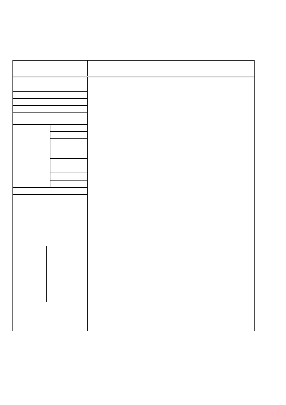
SPECIFICATIONS
Item Content
Dimensions ( W××××H××××D ) 73 .2cm ×58.7cm× 51 .8cm
Mass 48 .0 kg
TV RF System B/G, I, D/K, K1, M
Colour Syst em PA L / SEC A M / NTSC 3 .58 / N TSC 4.43
Stere o Sy st em
Teletext System Fastext (UK system) * [ * Without TE XT m od e : HV-29 LPZ
VL 46 .25 MHz ~ 1 68. 25 MH z
Rec eiving
Frequency
Intermediate
Frequency
Colour Sub Carrier
Frequency
Power Input AC 110V~2 40V , 50/60Hz
VH
UHF
CATV
VIF 38 .0 MHz
SIF 32 .5 MH z(5. 5MH z) / 32. 0MH z(6.0M H z) / 3. 15MH z(6.5 MH z) / 33 .5MHz (4.5 MHz)
PAL 4.43MHz
SE CAM 4.40625MHz / 4.25MHz
NT S C 3.58MHz / 4.43MHz
A2 (B /G) / NICAM (B/G , I, D/K, K 1)
WST(worl d s tan dar d Te xst )
17 5.2 5MH z ~ 46 3.2 5MHz
47 1.2 5MH z ~ 86 3.2 5 MH z
Mid (X~Z+2, S1~S10), Super (S11~S20) & Hyper (S21~S41
/HK
]
Power Consumption Max 2 54W / Avg. 170W
Aerial Input Term
Pictur e Tube 29 ”(68c m) m ea sured di a gon ally
High Voltage 31.5kV (At zero beam current )
Audio Powe r Output 20 W + 20W
Speake r
Vide o
Au di o (L /R ) 50 0m Vr ms(-4d Bs) , H i gh Impe dan ce
Input
Terminal
Output
Terminal Au dio (L/R) 500mVrms(-4dBs), Low Impedance
AV Compulink
Headphone jack
Remote Control Unit
S / Vide o
Comp onent Cb/Cr
Vide o
75Ωun ba l anc ed, C oaxial
+1.0kV
-1.5kV
φ10 cm Roun d t ype ×2 / φ3 .5cm R ou nd type×2
1Vp-p 75
Y : 1V(p -p ) Posi ti v e ( N ega tive s yn c pro vided ) 75
C : 0 .28 6V (p -p) (b urst s i g na l) , 7 5Ω
Y : 1V (p -p ), 75
Cb : B- Y 0 .7V (p-p ), 7 5Ω / Cr : R-Y 0 .7V(p-p), 75Ω
1V(p-p) 75Ω
Mono mini jack (φ3.5mm )
St ereo min i jac k (φ3.5mm )
RM-C214 (AA/R06 / UM-3 , Dry cell battery×2) : HV -29L PZ / HV -2 9L PZ
RM-C215 (AA/R06 / UM-3 , Dry cell battery×2) : HV - 29LPZ
Ω
Ω
De sign & speci f icatio ns ar e su bje ct to cha ng e wi thout no t ice.
Ω
/HK
/-A
/ HV -2 9LP Z
/EE
2
No.52012
Page 3

Z
SAFETY PRECAUTIONS
HV-29LP
1. The d esign of th is prod uct con ta ins sp ecial har d ware, ma ny
circuit s and components specially for saf ety purposes. For
con tinu ed pr ot ecti on , n o chan g es sh ould b e ma de to the o rig i nal
d esign un less a uth or ized in writi n g by th e manu fac t urer .
Replacem ent p arts m ust b e i d entic al to thos e u sed in th e or i gi n al
ci rcu its. S er v i ce sho ul d b e p er for m ed by qu alif ied p ers on nel
on ly.
2. Alte r ation s of the desi g n or circui tr y of t he prod ucts s h oul d not be
made. Any design alterations or additions will void the
manu fac t urer 's warra nt y and will f urth er r el i eve t he ma nufac tu rer
of r esp onsib ili ty for per s o na l injury or pr operty d am ag e res ul t ing
th erefr om.
3. Man y electr i c al an d m ec h ani ca l p ar ts i n th e pr od uc ts ha v e
special safety-related chara cteristics. T hese characteristics are
oft en no t e vi den t f r om v i sua l insp ecti on nor ca n t he pro tect io n
aff orde d by th em nece ssarily be ob tain ed b y u s in g r ep l ac em en t
com po nents rated for hig he r vo l tag e, watt age, etc . R ep lac em en t
p arts whic h have th ese sp ecial s afet y ch ar act erist ics ar e
ide ntified in the parts list of Ser vic e manua l. El ectric al
components having such features are identified by shading
on the sche mat ic s and b y (!!!! ) on the parts list in Service
manual. The us e of a sub sti tu te r ep lac em en t which do es n ot
h ave th e sam e s af ety c h ar ac t erist ics as t he reco mmen ded
replac ement par t sh ow n i n th e parts list of Ser v i ce man ual m ay
cause shock, fire, or other hazards.
4. Don't shor t between the LIVE s ide ground and ISOLATED
(NE UTRAL) side ground or EARTH side ground when
repairing.
Some model's power circuit is partly different in the GND. The
diff erenc e of th e G ND i s sho wn b y th e LIVE : (") side GN D, the
ISO LATE D(N EU TR AL) : ( #) side G ND and EARTH : ($) side
GND. D o n't sh ort b et ween th e LIV E s i d e GND an d
ISO LATE D(N EU TR AL) si de GND or EAR TH side GN D an d
n ever mea sure w it h a mea sur i ng a ppa r atus ( osci l lo scop e etc.)
th e LI VE sid e GN D an d IS OLA TED(NE UTRAL ) s ide G ND or
EARTH sid e GND at the s ame time.
If above not e will not be kept, a fuse or any parts will be broken.
5. If any repair has been made to the chassis, it is recommended
th at t he B1 set ting shou l d b e c h ec ked or adju ste d ( Se e
ADJUSTM ENT OF B 1 POW E R SUPPLY).
6. The high volta ge applie d t o th e pic tu re tu be mus t c on form with
th at sp ecifi ed i n S ervi ce man ual . E xc essi ve h i gh volt ag e c a n
cau se an i ncr e ase i n X- R ay em iss i on , arci ng an d possi b le
component damage, therefore operation under excessive high
voltage conditions should be kept to a minimum, or should be
preve nt ed. If s ever e arc ing occur s, r emov e t he AC power
immed iate l y and de ter m i ne th e ca us e b y vi sua l insp ec t ion
(incor r ec t in stal lat i on, cr ac ke d or melte d hi gh vo lt age harn ess,
p oor so ld er ing, et c.) . T o m ai nt ain the prope r mi n imu m le vel of
sof t X- R ay em iss i on, c omp on en ts i n th e hi gh voltag e c i r cuitr y
incl ud i ng t he pict ure tu be must be t he e xact r ep lacem e nts or
alte rn at ives ap pr ove d b y th e manuf ac t urer of th e c omplet e
prod uct.
7. Do not c hec k hi gh volt ag e by dr aw i ng an arc. Use a hi gh volt age
meter or a hig h v oltag e pr ob e wit h a V TVM . Discha rg e th e
picture tube before attempting meter connection, by connecting
a cl i p le ad to th e gr ou nd f rame and conn ecti n g th e oth er end of
the lead through a 10kΩ 2W resi sto r to the anod e butt on .
8. W hen se r vice is r equ ire d, ob serve th e or i gi na l lea d dr ess. E x tr a
prec aut i on sh ou ld b e given t o assur e cor r ect l ea d dress in th e
high vol tag e circui t a rea. W her e a s hor t c i r cuit h as occ u rr e d,
th ose co mpon ent s tha t indica te evide nce of ove r hea ting should
b e r e place d. A lways u s e th e manuf act ur er 's rep lacem ent
components.
9. Isolation Check
(Safety for Electrical Shock Hazard)
Af ter r e- ass embl in g th e p r odu ct, always per f orm an i solat io n
ch eck on the expo s ed me tal p ar ts of t he cabin et ( a nte nn a
ter m i na ls, vid eo /au dio i npu t and outpu t t ermi n al s, C on trol kn obs,
metal cabin et, sc r ew he ad s, ea rph one j ack, con tr ol s haf ts, etc.)
to be su re th e p r odu ct is s af e t o o pe rate with ou t d an ger of
elect rical shoc k.
(1) Dielectric Strength Test
The iso lation be tw een the AC pr im a ry ci rcu it an d al l me tal p arts
exp osed t o the us er, p ar ticular ly an y e xpos ed met al p art having a
retu rn p ath to t he c hass is sho uld withs tan d a vol t age of 3000 V
AC (r.m.s.) for a period of one second.
(. . . . W it hstan d a v o lt age of 110 0V A C (r .m. s.) t o an ap plianc e
rate d up to 12 0V , an d 3 00 0V AC ( r.m. s.) to an ap pl i an c e r at ed
200V or more, for a period of one second.)
This meth od of test r equi res a test equipment n ot g enerall y fou nd
in t he serv ic e trad e.
(2) Leakage Current Check
Plug th e AC l in e c ord d irect ly into the A C ou tlet ( d o not use a lin e
isol ati o n transf orm er du r ing this ch eck.). U sin g a " Lea kag e
Current T este r", me as ur e th e l ea k ag e cu rr e nt f rom eac h ex p os ed
metal p ar t of the cabine t, p art icu lar ly any e x pos ed me tal p art
h aving a re turn pa th to the ch assis , to a kn own go od ea rt h
grou nd (w a ter pip e, e tc.). An y l eaka ge c ur r en t must n ot e xceed
0.5mA AC (r.m.s.).
Howev e r, in trop ic al ar ea , th is mu st no t ex ce ed 0.2 mA AC
(r.m.s.).
"""" Alte rn at e Che ck M et hod
Plug th e AC l in e c ord d irect ly into the A C ou tlet ( d o not use a lin e
isol ati o n tran sfor m er dur i ng this c he c k.). Use an AC vo lt meter
h aving 1 00 0 oh ms pe r vol t or mor e s ens it i vity i n th e fo llowi ng
mann er . C on nec t a 1 50 0Ω 10W res ist or par a lle le d b y a 0 .1 5µF
AC-type c apa cit or bet ween an expo sed met al pa rt and a kno wn
g ood e ar th gr o und (water pi pe , etc.) . M eas ur e th e A C volt ag e
acr os s th e res ist or wi th th e AC vo l tm eter. Move th e r es i stor
con nec tion to e ach exp ose d me tal part, p art i cularly any exp osed
metal p ar t havi n g a r etu rn pat h to the ch assis, and m easu r e th e
AC vol tag e ac ros s the res ist or. No w , re v er se th e pl u g in th e AC
ou tl et and re pe at eac h mea suremen t. An y vol t ag e me asu re d
must no t e xc eed 0 .7 5V AC (r.m. s.) . This c orre spo nds to 0 .5mA
AC (r.m.s.).
Howeve r, in tropica l area, this must n ot exce ed 0 .3V AC ( r .m.s.).
This corresponds to 0.2mA AC (r.m.s.).
AC VOLT METER
(HAVING 1000 Ω /V,
OR MOR E SENSIT IVITY)
0.15μF AC-T YPE
PLACE THIS PROBE
1500 Ω 10W
GOOD EARTH GROUND
ON E A C H EX PO SE D
ME T AL PA RT
No.52012
3
Page 4
HV-29LP
Z
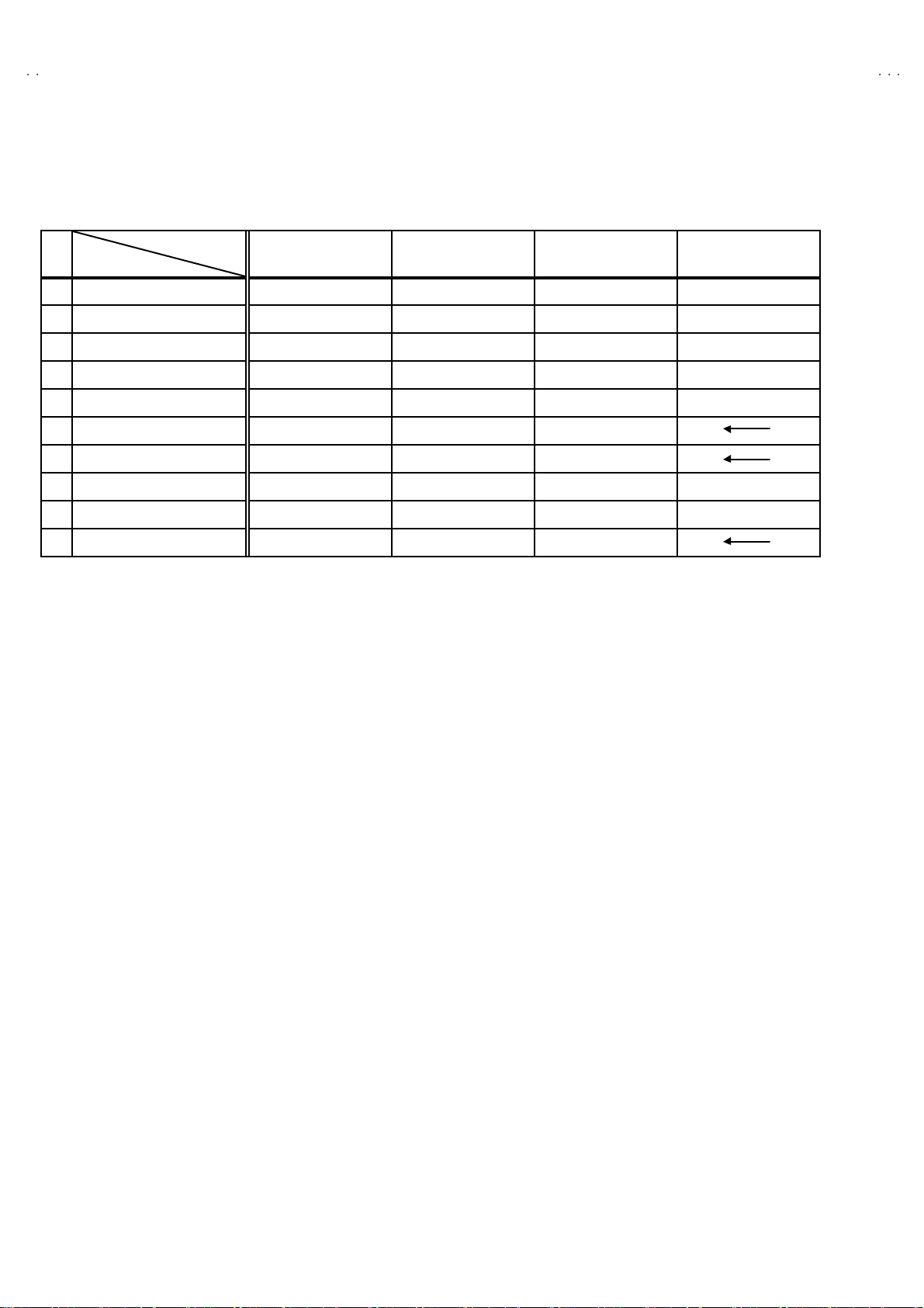
MAIN DIFFERENCE LIST
!!!!
Part n ame
MICOM PWB SMF0M90 1A -H2 SMF0M90 2A -H2 SMF0M90 3A -H2 SMF0M90 4A -H2
!
POWER CORD QM P4 0D 0-20 0J5 QMPN 050-20 0-E2 QMPR 010-20 0-E2 QM P4 0D 0-20 0J5
!
FRONT CABI .ASSY LC11193-0 08B- H LC1 1193-02 3A- H LC 111 93-0 08B-H
!
REAR COVER LC1 0763- 007B-HH LC1076 3-00 2D-H LC1 0763- 007B- HH
!
RATI NG LABEL LC2037 7-00 1B-H LC2 0377-01 2B- H LC2 0413-00 2B-H LC2 037 7-00 9B-H
!
INST BOOK LCT1215-001A-H LCT1217-001A-H LCT1215-001A-H LCT1218-001A-H
!
DIGEST MANUAL
!
CONVER SI ON PLUG
WARRANTY CARD
REMOTE CONTROL UNI T RM- C21 4-1C RM-C 215- 1C RM-C21 4-1C
Model name
HV-29LPZ HV-29LPZ
××
××
×××
/HK
HV-29LPZ
LCT1216-001A-H
QAM 0055 -001
/-A
FEATURES
HV-29LPZ
×
×
BT-54012-2
/EE
"
New c hassi s d esign ena bl e us e of an inte rac tive on screen
control.
"
The TELETEXT SYSTEM has a built-in FASTEXT (UK system),
and WST (world standard system) system.
*
E xc ept HV -2 9L PZ
"
Pure FLA T CRT repr od uc e f in e t extu r ed.
" Dig i Pu re pr o : Au to dig i pur e with m ot io n pi ctur e c ompe nsat i on.
"
Be caus e th is TV un i t corr esp on ds t o m ultipl e x br oa dca s t, u ser s
can enjoy music programs and sporting events with live realism.
In ad dition , BI LIN GU AL pro gr am s can be h ear d in th ei r or i g in al
language.
/HK
.
"
Built-in E CO (ECONOMY, ECOLOGY) MODE.
In acco rd ance with the br ig ht ness in a room, th e brigh tn ess
an d/ or con tr as t of th e pict ure c an be ad jus te d autom at ic al l y to
make the op ti mu m pi ctu re which is eas y on th e ey e.
4
No. 52012
Page 5
Z
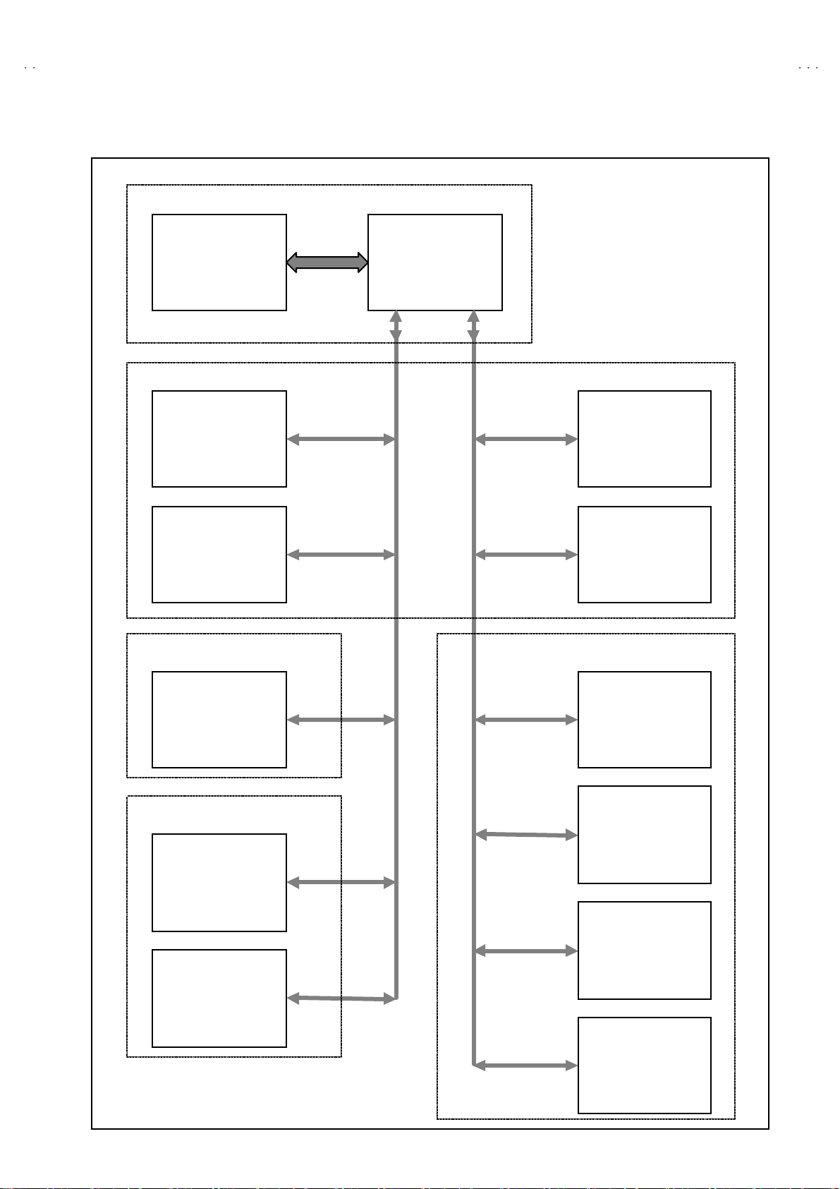
SYSTEM BLOCK DIAGRAM
MICOM PWB
HV-29LP
IC 00 4
MEMORY
SDA 0
SCL 0
SDA 2
SCL 2
IC 00 1
MICRO COMPUTER
SDA 1
SCL 1
MAIN PWB
IC 70 1
BBE CONTROL
IC 10 1
MULTI SOUND
PROCESSOR
IC 30 1
DEF & RGB
PROCESSOR
TU0 01
TUNER
SYNC S EP P WB 10 0Hz P WB
IC 30 1
SYNC SEP PWB
AV SW PWB
IC 10 1
SW
TU0 01
TUNER
IC 10 1
VIDEO PROCESS
&
CODEC MAIN
IC 15 1
VIDEO PROCESS
&
CODEC SUB
IC 20 1
SAMPLE RATE
CONVERTER
IC 30 1
ENHANC E
No. 52012
5
Page 6
HV-29LP
Z
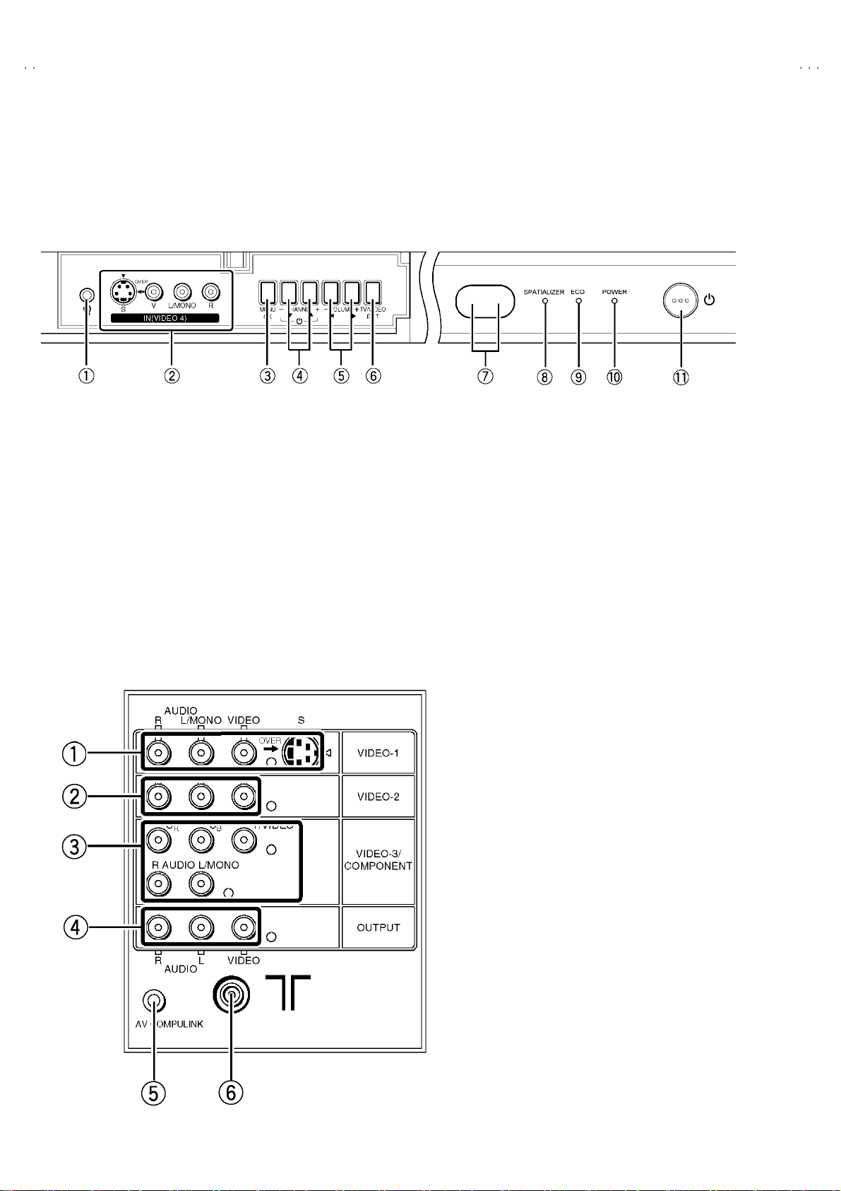
FUNCTIONS
■■■■ Front Terminal & Control
1 HEADPHONE jack 7 SENSOR ( Re mo te C ontro l & EC O)
2
VIDEO-4 terminal
3 MENU/OK Button 9 ECO LAMP
4
CHANNEL - /+ (MENU UP/DOWN) Button
5
VOLUME -/+
6 TV/VIDEO / EXIT Button ( Inpu t s el ect)
(S- VIDEO / VIDEO / L/MON O / R) 8
(MENU LEFT/RIGHT)
Button
SPATIALIZER LAMP
A
POW ER LA MP
B
POWER SW Button
(MAI N P OWER on an d off )
■■■■ Re ar Termin al
1VIDEO-1 (INPUT) terminal (S, V , L , R)
2
VIDEO-2
3 VIDEO-3 (INPUT) terminal (V/Y, Cb, Cr, L, R)
/ COMPONENT
4OUTPUT (AUDI O/VIDEO ) terminal (V, L, R )
5
AV COMPULINK terminal
6
AERIAL socket
(INPUT
) term inal
(V, L , R)
6
No. 52012
Page 7
Z
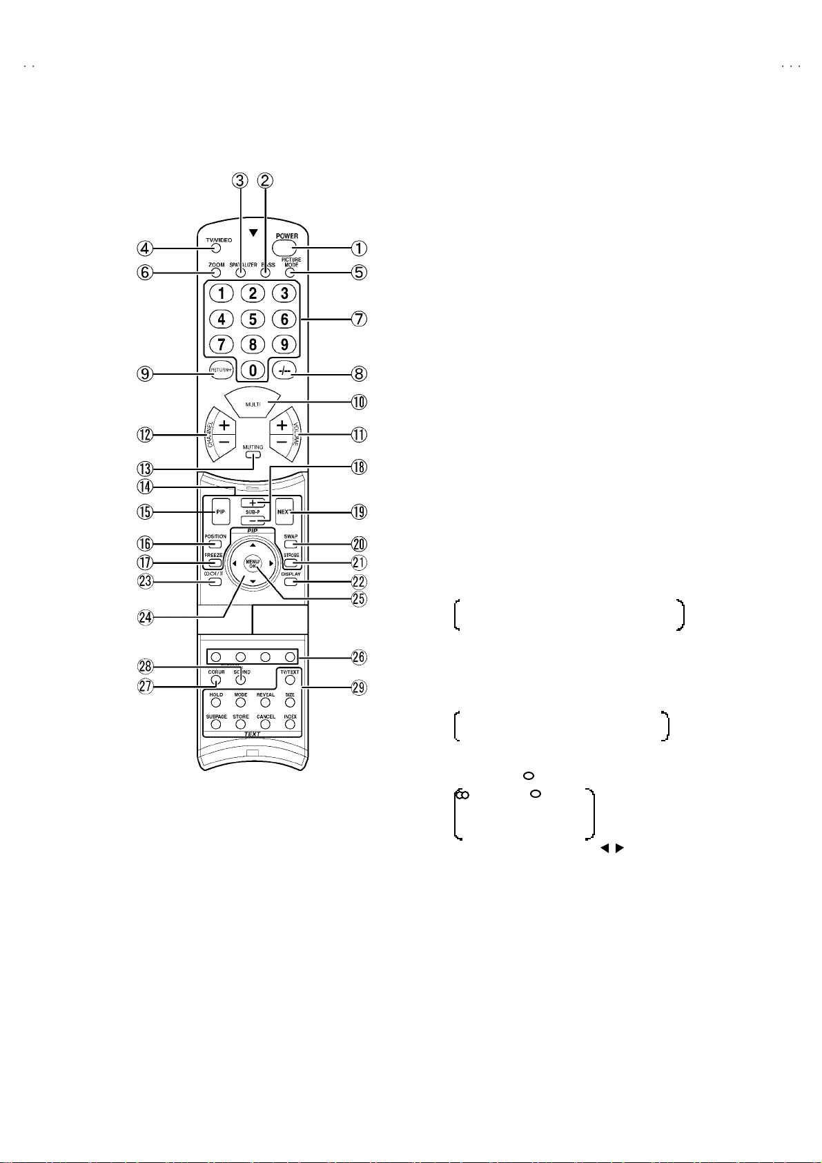
■■■■ Remote Control Unit
1
POWER Key
(SUB PO WER on and of f)
2
BASS Key
(SUPER B ASS function on or off)
3
SPATIAL IZ ER Key
(Choos e a m od e LIVE →MO NO →OFF)
4TV/VIDEO Key
5PICTURE MODE Key
(Choos e a m od e BRIG HT →STANDARD→ SOFT)
6
ZOOM Key
(Choose a mode REGULAR→ZOOM→16 :9)
7CHANNEL Key
8
-/- - Key
9
RETUR N + Key
AMULT I Key
B
VOLUME +/- Key
CCHANNEL +/- Key
D
MUTING Key
E
PIP MODE
FPIP Key
G
POSITION Key
HFREEZE Key
View t he MA IN pi ctu r e’ s f ro z en i ma ge as t he
SUB- PICTU RE.
I
SUB P (PIP)+&- Key
J
NEXT Key
KSWAP Key
L
STROBE Key
View t he MA IN-p ict ure as 1 5 c onsec utiv e
Still image.
MDISPLAY Key
N
STEREO Ⅰ/ⅡKey
: Stereo / : Mono
Ⅰ : Bilingual (subⅠ)
Ⅱ : Bilingual (subⅡ)
O
FUNCTION Key
(▲/▼& / )
PMENU/OK Key
Q
COLOUR Key
(Choos e the appropriate colour system.)
RCOLOUR SYSTEM Key
(Choos e the appropriate colour system.)
SSOUND SYSTEM Key
(Choos e the appropriate sound syst em.)
UTELETEXT Key
(W ith out H V- 29L PZ/HK)
HV-29LP
No. 52012
7
Page 8
HV-29LP
Z
)
SPECIFIC SERVICE INSTRUCTIONS
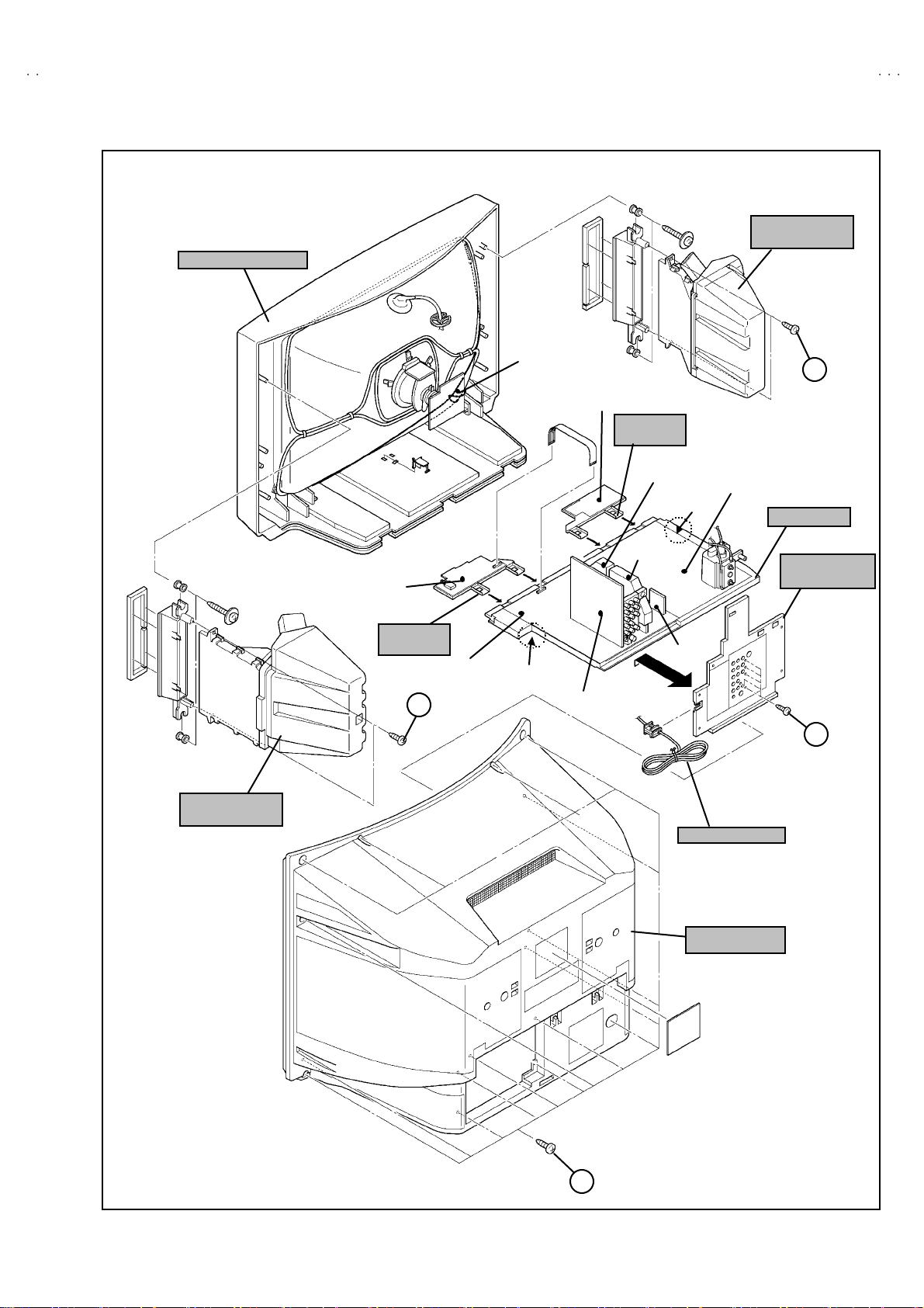
DISASSEMBLY PROCEDURE
REMOVING THE REAR COVER
1. Unplug t he po we r c ord.
2. Remove the 16 screws marked !!!! as sh own in th e Fig. 1.
3. Withdr a w t he r ear co ver to wa rd you .
REMOVING THE AV TERMINAL BOARD
" After removing the rear cover.
1. Remove the 5 scr ew s m ar ked
2. Withdraw the AV terminal board toward you.
""""
as sh ow n in t he Fig . 1.
REMOVING THE CHASSIS
"
After removing the rear cover.
1. Sl ight l y r ai se th e bo th si de s of th e c hass i s by h and and re mo ve
th e 2 claws under th e b oth s id es of the chas sis from th e fr ont
cab inet .
2. Withdr a w t he chass is backw a rd .
(If necessary, take off the wire clamp, co nnectors etc.)
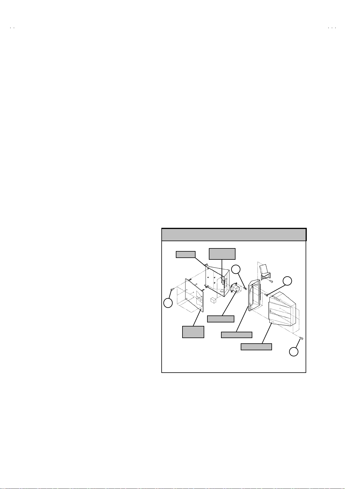
REMOVING THE DOME SPEAKER BOX / SPEAKER
" After removing the rear cover.
1. As s hown in Fi g. 1 , remo v e t he 2 screws mar ked
remove the dome speaker box.
2. Remove the 5 screws marked
remove the dome box.
3. Remove the 4 screws marked
remove the HONE RING.
4. Remove the 4 screws marked
remove the sp eake r.
5. Follow th e sa me step s when r em ov ing th e ot her h and d om e
speaker box / speaker.
NOTE : W hen r emovi ng the scr ews m arked
box, remove th e lo wer side sc rew fi rst , and then remo ve the
up per one .
$$$$
as sho wn i n th e F ig. 2, t he n
%%%%
as sho wn i n th e F ig. 2, t he n
&&&&
as sho wn i n th e F ig. 2, t he n
####
of th e dom e s p ea ker
####
, t hen
REMOVING THE TWEETER SPEAKER
" After removing the rear cover.
1. Remove the 7 screws marked '''' as s ho wn i n th e Fig. 2, t he n
remove the HONE PANEL.
2. The n rem o ve th e twe et er s p eak e r s crews to remo ve it.
CHECKIN G THE PW BOARD
To c h ec k the back s i de of th e PW B oard.
1) Pull out the chassis . (Refe r to RE MOV ING THE CHASSIS).
2) Erect the c hassis vertically so that you can easily check the
b ack side of the PW B oard.
[CAUTION]
"
When erecting the chassis, be careful so that there will be no
contacting with other PW Board.
"
Be fore tur n ing on po wer, ma ke sur e tha t the wire co nnecto r is
prop er l y con nected .
"
When co nduc ti ng a ch eck w i th p ower su ppli ed , b e sure to c onfirm
th at t he CRT E AR T H WI RE (B RAIDED AS S’Y) is co nne c ted t o
th e C R T SOC KE T PW b oard.
WIRE CLAMPIN G AND CABLE T Y ING
1. Be sure t o clamp th e wir e.
2. N ever remo ve th e cable ti e used f or tyi ng the w i re s to gether.
Sh oul d it be i n adv e rt ent l y rem ove d, b e su r e to tie th e wires w it h
a n ew c able tie.
DOME SPEAKER BOX
HORN
G
(×7)
HORN
PANEL
SP EAKER
(Tweete r
SP EAKER
HORN RI NG
F
(×4)
DOME BOX
E
(×4)
D
(×5)
8
Fig . 2
No.52012
Page 9
Z
(×5)
(
)
FRONT CABINET
FRONT
C ONT RO L
PWB (1 /2 )
CRT
SOCKET
PWB
FRONT
C ONT RO L
PWB (2 /2 )
C ONT RO L
BASE
MICOM
PWB
10 0Hz
PWB
HV-29LP
DOME
SP EAKER BOX
C
POWER & DEF
PWB
CLAW
CHASSIS
AV
TERMINAL
DOME
SP EAKER BOX
C ONT RO L
BASE
C
BL K
CLAWMAIN PWB
AV SW PWB
PWB
B
POWER CORD
REAR COVER
A
×15
Fig . 1
No.52012
9
Page 10
HV-29LP
Z
A
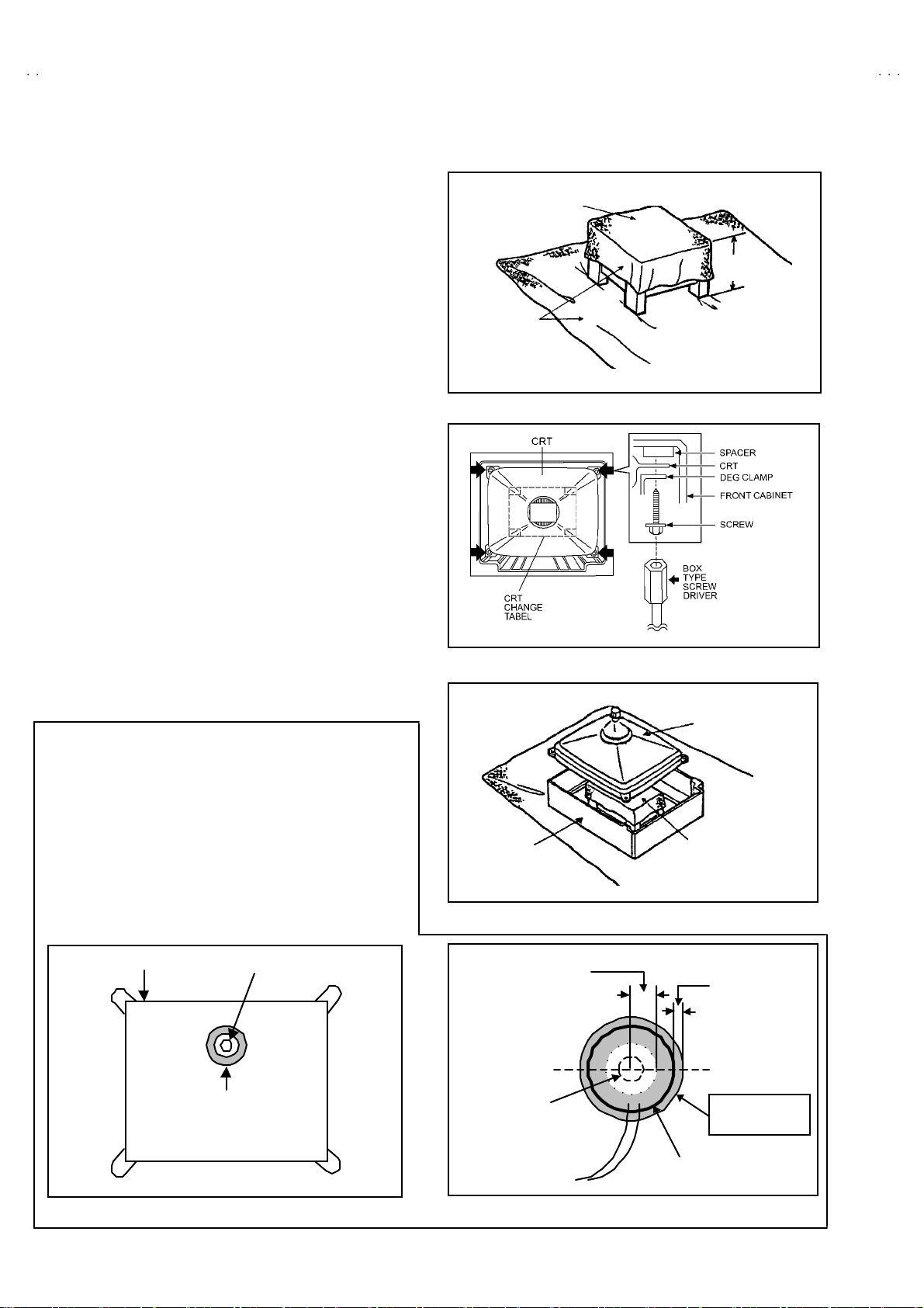
REMOVING THE CRT
∗
Replacem en t of th e CRT s ho ul d be p er for m ed b y 2 or mor e
p ers ons.
• After removing the cover, chassis etc.,
1. Pu tting th e CRT c han ge ta ble o n s of t cloth , th e C R T cha nge ta bl e
sh ould al so b e c over e d w i th s uch soft clot h (s ho wn i n Fig. 3) .
2. While kee pin g th e s urf ace of C RT down , m ount the TV s et on t he
CRT change table balanced will as shown in Fig.4.
3. R em ov e 4 sc rews mark e d by arro ws with a box ty p e scr e w dri ver
as s hown in Fig. 4.
• Si nc e th e cab i net will dr op whe n scr ews h av e be en remove d, b e
sure t o su pp ort t he cabinet with hands.
4. After 4 screws have been removed, put the cabinet slowly on
cloth (At th is time, be ca refully so as not to damage th e front
sur fac e of th e c abin et) s h ow n i n Fig. 5.
• The C RT sh ould b e ass embled accor di n g to th e o pposi te
sequence of its dismounting steps.
∗
The CRT change ta ble sh ou ld pr ef erab ly be smaller tha t th e C R T
sur fac e, and its h ei gh t be abo ut 35c m. (F ig.3 )
∗ Ab out CRT S pacer ( F ig .4 )
An appr o pria te CRT spa cer shou ld be us ed i n t he co rr es p on ding
CRT in acc ordan c e with the t yp e of t he CRT.
When a CRT i s r ep l ace d, sp ecial att enti o n s ho ul d be p aid to this
matter.
CRT CHANGE TABLE
PPROX.
35 cm
CLOTH
Fig. 3
COATING OF SILICON GREASE FOR ELECTRICAL
INSULAT ION ON THE CRT ANODE CAP SECTION.
•
Subse qu ent to re pl ace me nt of th e CR T an d HV tr an s for m er o r
repa ir of th e a no de ca p, etc. b y di smou nti n g the m, be su r e to
coa t si l ic on greas e f or elect ric a l insul at ion as sh own in Fig.6 .
Wipe a r oun d the anod e butt on wi th clea n and dry cl ot h. (Fi g.6 )
Coat sili con gr ea se on t he section arou nd the an od e b utt on. At
this tim e, take care so th at any silico n greases dose not stick to
the ano de button. ( Fig.7)
★★★★
Sil icon grease product No. KS - 650N
CRT
An od e butt on
Silic on gr eas e
coating
CABINET
Ap prox.
20mm (Do not
coat grease on
this section
An od e butt on
(No sti c king of
silicon grease)
Fig. 4
CRT
CRT
CHANGE TABLE
Fig. 5
Silic on gr eas e
sh ould be coa ted
b y 5mm or m or e
fr om th e outs id e
diame ter of
an od e c ap.
Coat in g posit io n
of sili co n g r ease
An od e cap
Fig. 6 Fig. 7
10
No. 52012
Page 11
Z
REPLACEMENT OF MEMORY ICs
O
FUNCTION k
1. Memory ICs
This TV use memory ICs. In the memory ICs, there are memorized data
for correctly op er atin g th e video an d def l ection circ u its . Wh en r ep lac i ng
memory ICs, be s ure t o us e IC s wr itte n with the i ni tial values of da ta.
HV-29LP
2. Procedure for replacin g memory ICs
(1) Power off
Switch the p ow er of f and un plug th e pow er cor d f ro m t he wall outlet.
1. IF 2. V/C
3. AUDIO 4. DEF
5. VS M PRES ET 6. S TATUS
7. PI P 8. W B PR E SET
9. SHIPPING(OFF) 0. BUS FREE
SERVICE MEN U
(2) Repla ce ICs.
Be sure to use memory ICs written with the initial data values.
1-0 : SELECT DISP : EXIT
(3) Powe r on
Plug th e pow er c ord int o th e wall ou tlet and s witch the pow er on .
Fig.1
(4) Check and s et SY ST EM CO NSTA NT SET :
****
It must not adjust witho ut signal.
1) Press the D ISP LA Y ke y an d t he PICTU R E T U BE key of th e R EM OT E CON T RO L U N IT simultan eo usly .
2) The SERVICE MENU screen of Fig. 1 will be displayed.
3) W hi le th e SERVI CE M ENU i s d is play e d, p r ess t he D ISP LA Y k ey an d PI C T URE TU BE ke y sim ulta neo usly, an d t he S YSTE M
CONSTANT S ET scr een of Fig. 2 w i ll be di splay ed.
4) Check th e set ting valu es of the S YSTEM CONSTA NT SET of T ab l e 1 . If th e valu e i s d if fer ent, sel ect the se tti ng it em wi th the
FUNCTION UP/DOWN key, and set the correct value with the FUNCTION -/+ key.
5) Press the MENU(OK) key to memorize the setting value.
6) Press the INFORMATION key, and re turn to the no rmal scr e en.
SERVICE MENU KEY
SY STEM C ON STANT S ET
1. TEXT
**
K
+ : STORE DISP : EXIT
Fig.2
2. BLUE BACK ME NU
3. E.M.C
4. WHITE BACK
5. COLOUR AUTO
6. PICTURE TILT
**
**
**
**
**
(5) Sett ing of re ceive channe ls
Se t th e r ec eiv e ch anne l.
For setting , r ef er to the OPE RATING INS TRUCTIONS.
(6) Setting of SERVICE MENU
Ve rif y the set ting it ems of the SE R VICE MENU of Tabl e 2, and
reset whe re nec es sary.
For setting , r ef er to the SE RVIC E ADJUSTMENTS.
(7) User se tting s
Check th e us er s ett ing valu es o f T ab l e 3 , and if sett ing value is
diff erent , set th e c orrec t val u e.
For setting , r ef er to the OPE RATING INS TRUCTIONS.
ZO OM
(ASPECT)
key
SETTING IT EM
SELECT key
(Numbers key)
PICTURE
CONTENT S
key
PIP key
(UP/DOWN &
LEF T/RIGHT key)
MENU/OK key
MEMORY
(STO RE )
key
SERVICE
MENU/
&SYSTEM
CONSTANT
key
ey
No. 52012
11
Page 12

HV-29LP
Z
S ET T I NG VALU ES OF SY STE M CON STANT S ET (TABLE 1 )
MODEL No.
HV-29LPZ HV-29LPZ
Setting item
1. T EXT YE S YE S NO YE S
/-A
HV-29LPZ
/HK
HV-29LPZ
/EE
2. BL UE BAC K MUTE NO YE S NO
3. E. M. C NO
4. W HITE BACK NO
5. COLOUR AUTO NO YES NO
6. PICTURE TILT YES
←←←
←←←
←←←
SERVICE MENU SETTING ITEMS (TABLE 2)
Setting item Setting value Setting item Setting value
1. IF 1. VCO
2. ATT O N / OFF
2. V / C 1. RGB BLK
2. W D R R
3. W D R G
4. W D R B
5. BRIGHT
6. CONTRAST
7. COLO UR
8. TIN T
9. SHAR P
10. VCO A DJ .
11 . VID A DJ.
12. SY NC S LICE
5. VSM P RESET
BRIGHT
STANDARD
SOFT
6. STATUS
(Do not a dju st)
1. CONT.
2. BRIGHT
3. SHAR P
4. COLO UR
5. TIN T
1. SOF T
2. TELETEXT
3. AS PECT
←
←
3. AUDIO
(Do not a dju st)
4. DE F. 1. V- SH IFT
1. ER R LIMIT
2. A2 ID THR
3. SY STEM
2. V-SIZE
3. H-CENT
4. H-S IZ E
5. TR APE Z
6. EW - PIN
7. COR-P IN
8. COR-UP
9. COR-L O
10. ANGLE
11 . BOW
12. V-S.CR
13 . V.L IN
14. V.BLK-UP
12
7. PIP 1. PIP VCO ADJ
2. PIP VID AGC
3. PIP SYNC S LICE
8. WB PRE SET 1. WDR R
2. W D R G
3. W D R B
No. 52012
Page 13

Z
USER SETTING VALUES (TABLE 3)
Setting item Setting value Setting item Setting value
MAIN POWER SW OFF SUB P OW ER ON
SHIPPING CHANNEL PR1 DISPLAY INDICATED
PRES ET CH AN NEL
PICTURE SE TTING INSTALL
PICTURE MODE BRIGHT LANGUAGE ENGLISH
WHITE MODE MID EDIT " PRES ET CH AN NEL O NLY
ECO MODE OFF
PICTURE FEATURES FEATURES
DIGITAL VNR AUT O SLEEP TIMER OFF
DIGIP URE PRO AUTO BLUE BACK ON
COLOUR S YST E M " TV : Dep ends on PR/CH AUTO S HUT O FF OFF
See ; OPE RATIN G
INSTRUCT IONS.
" EXT : AUTO
VOL UME LEVEL 10
"
OTHER : NO N (SPACE)
VIDEO-3 SETTING COMPONENT
HV-29LP
ZOOM REGU LA R CHI LD LO CK OF F ( for al l t he chann el s)
PICTURE TILT CENTER CHANNEL G UARD ALL CH : OFF
SOUND
BA SS
TR EBL E
BALANCE
SP ATIAL IZER
CENTER
CENTER
CENTER
OFF
BE E ON
SUPE R B AS S ON
AI VOL UME ON
No. 52012
13
Page 14

HV-29LP
Z
SERVICE ADJUSTMENTS
BEFORE STARTING SERVICE ADJUSTMENT
1. Ther e ar e 2 w ays of ad ju st in g this TV: One is wi th t h e
REMOTE CONTROL UNI T and the other is the conventional
method using adjustment parts and components.
2. The setting (adjustment) us ing the REMOTE CONTROL
UNIT is made on the ba sis of th e initial se tting values . Th e
se tting va lu es whic h adjust the sc ree n to the o p t imum
condition can be different from the initial setting values.
3. Make s ur e th at conn ect i on i s c orrec t ly ma de t o AC p ower
source.
4. Tur n on th e pow e r of th e T V and m eas u r in g i ns tr um en t for
warmin g up f or at least 30 min ut es bef ore sta rt in g adju stm ent .
5. If th e r ec ei ve or i np ut sig nal is not sp eci fi ed , use t he m ost
ap pr op ri a te s ig na l f or a dj ust me nt.
6. Never touch parts (suc h as var iable r esis tors, t r ansf orme rs and
condensers) not shown i n the adjustm ent items of this
se rvic e adju st me nt.
7. Pr ep arati o n for ad j ustm en t (pres ettin g):
Unles s oth erw is e sp eci fi ed in th e a dj us t ment it em s , p res e t th e
follo win g fu nct ions with th e REMOTE CONTROL UNIT:
" Setting p ositi on
PICTURE MO DE (VSM) STANDARD
SLEEP TIMER OFF
BALANCE CENTER
ECO OFF
ZO OM REGUL AR
MEASURING INSTRUMENT AND FIXTURES
1. DC voltmeter (or digital voltmeter)
2. Oscilloscope
3. Sign al g en erat or (Patt er n g en erat or) [ PAL / SE CAM / NTSC]
4. Remote control unit
ADJUSTMENT ITEMS
●
Check ing i t ems.
●
Adjustment of FOCUS/SCREEN.
●
VS M p r es et sett in g.
●
VIDEO / CHROMA circuit adjustment.
●
DEFLECTION c ircuit adjustment.
●
AUDIO circui t a djust ment. (Do not adjust)
14
No. 52012
Page 15

Z
ADJUSTMENT LOCATIONS
C
5p
5
CN0
JFC
U/
OKCH U
)
S
d
S
C9 0
CDS
Spe ake
CN00 3
CN00
C
CN004CN00 5
3
CN002C
SC
OC US
OC US
CN013
(
)
(
)
J
HV-29LP
FRONT
FRONT
FRONT CONTROL PWB (1/2)
PO WER SW
Power cor
POWER
F901
PW
ECO
1
P E T IA LI ZE R
LF901
MAIN PWB POWER&DEF PWB
N111
r
AV SW PWB
TUNER 2
W
R
MICOM P WB
7
10 0H z PW B
CN 00 2
TV/VIDEO EXT
W DEG
FRONT CONTROL PWB (2/2)
VOL UP
VOL DOWN
H DOWN
P
MEN
R4 L4 V 4
IN (VIDEO-4
IN
To AV SW P WB
HEA D
PHONE
FRONT
FRONT
FRONT
F
F. CONT.(L) PWB
YH C
VR 2
CN 00 1
CR T
XV C O IL
SYNC
PWB
TUNER
S
IN
BLK P WB
1
CN 01 3
CN 00 6
HV
X
HVT
14
1
1pin:B1(TP-91)
2pin:N
3 pin :X- RAY
4pi n:X-RAY
in:GND
ANT-I N
CRT SOCKET
PWB
F
F
2 VR
1 VR
R EEN VR
YV
VR 1
TP-E
TP-Y
(SO LDE R SI DE)
E1
TP-47B
VM
CN 01 4
TOP
VM
No. 52012
15
Page 16

HV-29LP
Z
BASIC OPERATION SERVICE MENU
1. TOOL OF SERVICE MENU OPERATION
Operate the SERVICE MENU with the REMOTE CONTROL UNIT.
2. SERVICE MENU ITEMS
With the SERVI CE MENU, var i ou s sett ings ( ad ju s tm en ts) c an b e m ade , a nd th ey are b r oad ly classif i ed i n th e f ol lowing ite ms of set tings
(adjus tments ):
(1) 1. IF ・・・・・・・ ・・・・・・・・・・・・・・・・・・・・・・・ This m od e adjust s the setting values of the IF circu it.
(2) 2.V /C ・・・・・・・ ・・・・・・・・・・・・・ ・・・・・・・・・ T his mod e adjust s the setting values of the VIDEO / CHROMA ci rcuit.
(3) 3.AUDIO ・・・・・・・・・・・・・・・・・・・・ ・・・・・・ Thi s m od e adjust s th e setti ng valu es o f th e SOUND circuit . ( Do n ot adju s t)
(4) 4. DEF ・・・・・・・・・・・・・・・・・・・・ ・・・・・・・・・ This mo de adj us t s th e se tti ng valu es of th e DEFLEC T ION ci rc uit for eac h aspect mod e gi ve n
below.
ZOOM ( A SPECT) V. FRE Q.
REGULAR 100Hzi / 60HzP
ZOOM ↑
16 : 9 ↑
(5) 5.VSM PRESET・・・・・・・ ・・・・・・・・・・・・・ Thi s mod e adj ust s th e i n iti a l s ett in g va lues of Br igh t, S tan da rd & s oft.
(VSM : Video Status Memory)
(6) 6.S T AT US ・・・・・・・ ・・・・・・・・・・・・・・・・・・ It is no r equ ire me nt t o adj us tme nt.
(7) 7. PIP ・・・・・・・・・・・・・・・・・・・・ ・・・・・・・・・ This m ode adjust s th e se tti ng valu es o f th e PI P circuit. (P IP : Pictu re In Pictu re)
(8) 8.WB PRES ET ・・・・・・・ ・・・・・・・・・・・・・・ T hi s mod e adj us t s th e se tting valu es o f th e W H IT E B ALANCE.
(9) 9.SHIPPI NG (OFF ) ・・・・・・・ ・・・・・・・・・・・ T hi s mod e adjust s th e setti ng valu es o f th e ch an ne l p res etti n gs .
If you turn the SHIP PING posi tion set ON.
Thi s se tting be c om es c hann el pres etting a uto ma ti cally.
Also you tur n th e TV powe r off, this s etting beco me OFF position automatically.
(10) 0. BUS FRE E
・・・・・・・ ・・・・・・・・・・・・・ ・・
It is n ot req uir ement to ad justme nt.
16
No. 52012
Page 17

Z
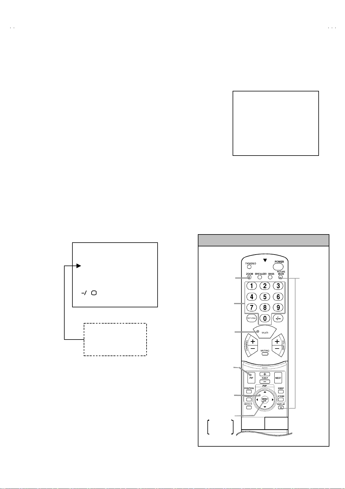
3. BASIC OPERATION OF SERVICE MENU
(1) How to enter SERVICE MENU
Pr es s th e PI CTU R E M ODE ke y and th e D ISP LA Y ke y of the
REMO TE CONTROL UNIT simultaneously, and the SERVICE
MENU screen of Fig. 1 will be displayed.
(2) Selecti on of S UB MENU SCREEN
Press one of keys 1
~
0 of the REMOTE CONTROL UNIT and
select the SERVICE MENU S CRE EN (S ee Fig. 3), f orm the
SERVICE MENU.
SERVICE MENU
→
SUB ME NU
1. IF
2. V / C
3. AUDIO (Do not adj.)
4. DE F.
5. VSM PRE SET
6. ST ATUS (Do not adj.)
7. PI P
8. WB PRE SET
9. SHIP PING (OFF )
0. BUS FREE
ZO OM
(ASPECT)
key
SETTING IT EM
SELECT key
(Numbers key)
SE RVICE MENU
SERVICE MEN U
1. IF 2. V/C
3. AUDIO 4. DEF
5. VS M PRES ET 6. S TATUS
7. PI P 8. W B PR E SET
9. SHIPPING(OFF) 0. BUS FREE
1-0 : SELECT DISP : EXIT
Fig.1
SERVICE MENU KEY
HV-29LP
SERVICE
MENU/
&SYSTEM
CONSTANT
key
PICTURE
CONTENT S
key
PIP key
FUNCTION ke y
(UP/DOWN &
LEF T/RIGHT key)
MENU/OK key
MEMORY
(STO RE )
key
No. 52012
17
Page 18

HV-29LP
Z
O
O
O
SERVICE MENU SCREEN
SUB MENU
SERVICE MENU
SERVICE ME NU
1. I F 2. V /C
3. AUDIO 4. DEF
5. VSM PR ESET 6. STAT US
7. PIP 8. WB PRESET
9. SHIPPING(OFF) 0. BUS FREE
1 - 0 : S ELE C T DI SP : EX IT
BRIGHT
STANDARD
SOFT
1. CONT.
2. B RIGH T
3. SHARP
4. COLOUR
5. TINT
1. SOFT
2. TELE TEXT
3. ASPE CT
1. PIP VCO ADJ
2. PIP VID AGC
3. PIP SNC SLI
5. VSM PRES ET
VSM PRESET STD
1.CONT
- / + : STO RE DISP : EXIT
K
***
6. STATUS (Do not adjust)
STATUS
1 . S OF T
- / + : STO RE DISP : EXIT
OK
***
7. PI P
PIP
1. PIP VCO ADJ
- / + : STO RE DISP : EXIT
K
AUTO
***
1. I F ( CW)
IF SERVICE MENU
1. V CO
2 . A TT O N / O F F
1 - 2 : S ELE C T D I S P : EX IT
2. V/C
V/C
PAL
1. R G B. BL K
- / + : STO RE DISP : EXIT
OK
****
3. AUDIO ( Do not adj ust)
VCO (CW)
MAIN SUB
T OO HIG H
ABOVE REF
JUST REF
BELOW REF
T OO LOW
IF A TT ON /O FF
- / + : STO RE DISP : EXIT
OK
.**
**
***
***.
****
******
DISP : EXIT
MHz
**
**
****
(ON or OFF)
1. RGB BLK
2. WDR R
3. WDR G
4. WDR B
5. BRIGHT
6. CONTRAST
7. COLOUR
8. TINT
9. SHARP
10. VCO ADJ
11. VID AGC
12. SYC SLI
AUDIO
1. E RR LIMIT
ERROR _ RA T E=
***
****
1. ERR LIMIT
2. A2 ID THR
3. SY STEM
8. WB PRESET
- / + : STO RE DISP : EXIT
K
4. DEF
DEF REGUL AR
1. V-SHIF T
- / + : STO RE DISP : EXIT
OK
***
***
******
Hz
*** *
(
*** *
1. V-SHIFT
2. V-SIZE
3. H-CENT
4. H-SIZE
5. TRAPEZ
6. EW-PIN
7. COR-PIN
8 . C O R- UP
)
9. COR-LO
10. ANGLE
11. BOW
12. V-S.CR
13.V.LIN
14. V.BLK-UP
1. WDR R
2. WDR G
3. WDR B
WB PRESET
1. W DR R
- / + : STO RE DISP : EXIT
OK
***
***
******
**
Fig. 3
18
No. 52012
Page 19

Z
(3) Method of Setting
" Meth od of Set ting 1. IF
[VCO] ・・・・・・・ ・・・・・・・・・・・・・・・・・・・・ * It mu st n ot adju st wi thout signa l
① 1 K ey ・・・・・・・・・・・・・・・・・・・・ ・・・・・ Se lect 1 .IF.
② 1 K ey ・・・・・・・・・・・・・・・・・・・・ ・・・・ Se le ct 1 . VCO ( CW)
Check th e ar r ow p os i ti on betw ee n the ABO VE RE F. an d B ELOW R EF .
③
④
"
Meth od of s ett in g 2.V/C, 4.DEF, 5.VSM PRE SET, 7 .PI P and 8.W B PRES ET.
① 2, 4, 5, 7 & 8 Key ・・・・・・・ ・・・・・・・・ Select one from 2. V/C , 4. DE F, 5 . V SM PRESE T, 7. PIP & 8.WB PR ES ET.
② FUNCTION U P/ DOWN K ey ・・・・・・ Select s etting i tems.
③ FUNCTION - /+ ・・・・・・・ ・・・・・・・・・・ Se t ( adjust) th e se tting valu es o f th e settin g it ems.
④ MENU (OK) Key ・・・・・・・・・・・・・・・ Memorize the setting value.
⑤ DISPL AY (DI SP) K ey ・・・・・・・ ・・・・ Ret urn to the SER VICE ME NU scr ee n.
" 3. AUDIO, 6. STATUS, 9. SHIPPING(OFF) & 0. BUS FREE.
・・・・・・・ ・・・・・・・・・・・・・ ・・・・・
2 K ey
DISPLA Y(DISP) Ke y
・・・・・・・ ・・・・・
Select 2 .ATT O N/OFF (Str ong Elec tr ic Field : O N / G enerally Electric Field : OFF)
Retu rn t o the SERVICE MENU screen.
(Bef ore st orin g t he s ett in g valu es in me mo r y, do no t pres s t he CH, TV , P OW ER ON / OFF key -
if you do, the values wi ll not be sto red in mem ory.)
It is not r equ i re me nt to adj u s tm ent .
HV-29LP
(4) Rele as e of SER V ICE M E NU
1) Af ter co mpl eti ng the s e tting , ret urn t o t he SERVICE ME NU, then agai n p ress th e D ISP LA Y (DI SP) ke y.
No. 52012
19
Page 20

HV-29LP
Z
ADJUSTMENT
CHECKING ITEM
Item
Check of B1
Power Supply
Measuring
instrume nt
Signal
Generator
DC vo ltmeter
Remote
Control unit
Test point Adjustment part Description
TP-91(B1)
TP-E(#### )
[X connector
on POWER
DE F PW B ]
1. RGB BLK 1. R eceive any bro adc ast.
2. Pr es s the ZOOM k ey an d se l ect t he F UL L mo de .
3. Select 2 . V/ C from th e S ERVIC E MENU.
4. Select 1 . RGB BLK with function UP / DOW N ke y.
5. Pr ess t he fun ction ( ) key t o f in d t he cut off s creen ( Bl ac k
screen).
6. C on nect a D C voltm et er t o TP- 9 1(B 1) a nd TP-E(#).
7. M ake sure t hat th e volt ag e is D C 13 9.9 ±2.0V.
8. Press the function ( ) key t o return t o service menu.
Check of High
Volt age
Signal
Generator
DC volunteer
Remote
Control unit
Check o f VC O Remot e
control unit
IF SERVICE MENU
1. VCO
2. ATT O N/ OFF
1-2 : SELEC T
CRT anode
Chassis GND
DISP : EXI T
1. RGB BLK 1. R eceive any bro adc ast.
2. Pr es s the ZOOM k ey an d se l ect t he F UL L mo de .
3. Select 2 . V/ C from th e S ERVIC E MENU.
4. Select 1 . RGB BLK with function UP / DOW N ke y.
5. Pr ess t he fun ction ( ) key t o f in d t he cut off s creen ( Bl ac k
screen).
6. Connect a DC voltmeter to CRT ANODE and chassis GND.
7. M ake sure t hat th e volt ag e is D C 3 1.5kV .
8. Press the function ( ) key t o return t o service menu.
* Rem ove th e pro be bef ore re mo ving th e ear th c lip .
1. VC O
2. AT T ON/OFF
"
Und er n orm a l c onditions, no ad just ment is r e quir ed .
" Confirmation adjustment.
1. Select 1 .IF f rom the SERV ICE MEN U.
2. The n se lect 1.VCO fr om the IF S ERVICE MENU.
3. R eceive any br o adc ast.
4. Check th e MAIN a rr o w ( ) posi ti o n betw ee n the A BOV E
REF. and BELOW REF.
5. Press the MENU (OK) key and receive any broadc ast with PIP
Button .
6. C heck th e SU B arrow ( ) posi ti on b etwee n th e A BOV E RE F
an d B ELOW RE F.
+1kV
-1.5kV
20
* The arrow ( ) position means AFC voltage level.
* 2. ATT ON/OFF : G enerall y Electric F ield : OFF
: Strong Elec tric Fie ld : ON
*
Change the M AI N and SU B by MENU/OK ke y .
VCO(CW)
TO O HI GH
ABOVE REF
JUST REF
BELOW REF
TO O LO W
****
MAI N SUB
DISP : EXIT
MHz
No. 52012
Page 21

Z
ADJUS TMENT OF FOCUS & SCREEN
Item
Ad justment of
FOCUS
Measuring
instrume nt
Signal
generator
Test point Adjustment part Description
HVT
FOCUS 2 VR
FOCUS 1 VR
SCREEN VR
FOCUS 1 VR(In HVT)
FOCUS 2 VR(In HV T)
HV-29LP
1. R eceive a cross -hatc h sign al.
2. Pr es s the ZOOM k ey an d se l ect t he re gu lar m ode .
3. By t urning th e FOC U S 1 VR , a djus t th e t o mak e th e v er ti c al
lines as fine and sharp as possible.
4. By tur ni n g th e FOCUS 1 VR, ad jus t the pictur e so th at th e 5t h
ver tic al l ine fr om le ft si d e of the cr oss-ha tch p ict ur e b eco me s
thin nes t.
5. By t urning th e FOCUS 2 VR ( In CRT SOC KE T PW B ), adju st
the 3rd horizontal line from the upper side may become
un if or m at the line c enter an d it s perip hery .
6. C ar r y out adj ustm en t b y rep eat in g the ste ps 3, 4 and 5 abou t.
7. Make su re th at th e scr een is d ar k e ne d, th e lin es rem ain i n
g ood focu s.
Ad justment of
SCREEN VR
12 34 5
Signal
generator
V/C
1. RGB _ BLK
PAL
FOCUS 1 VRFOCUS 2 VR
1
2
3
SCREEN VR
(In HVT)
1. Recei ve a wh ol e bl ac k signa l .
2. Press the ZOOM key an d se lect t he regu lar mode .
3. Se lect 2 . V/ C from th e SERVICE MENU.
4. Rota te th e SC R EEN VR (I n HVT) clock wise( fr om 1→0→1)
from the full counterclockwise sl owly and stop it at th e p oint
where “ C LOW ” statu s (marked in Fig. ) c h ang es fr om 1 to
0 (whic h is i nd ic ated at the 3 rd co lumn from th e ri g ht.).
00
* “ C LOW” : c ontro l l oo pou t of wind ow .
- / + : STORE DISP : EXIT
OK
1
0 0 0 0 0 1 0 0
SERVICE MODE SCREEN
CLOW
status
No. 52012
21
Page 22

HV-29LP
Z
VSM PR ESET S ETTI NG
Item
Setting of
VS M PRESET
Measuring
instrume nt
Remote
control unit
Test point Adjustment part Description
1. CONT.
2. BR I G HT
3. SHARP
4. COLOUR
5. TIN T
1. Se lec t 5 .VS M P RESET from th e S ER VICE ME NU.
2. Select STD with the PICTURE MODE key of the remote control
un it.
3. Ad ju s t t he fu nc ti o n UP/ DOW N a nd LE FT/RIGH T key to br i ng
th e set value s of 1. CON T ~ 5. TINT to the val u es sh ow n in
th e t able.
4. Press the MENU/O K key and memorize the set valu e.
5. Respectively se lect the VSM PRESET mode for REGULAR
an d BR IGH T, and make simi l ar ad j us tm e nt as i n 3 abo ve.
6. Press the MENU/O K key and memorize the set valu e.
∗
Refe r to OPERATING INSTR UCTIO NS f or th e PICTURE
MO DE .
Setting item
VS M pr ese t mo d e
BR IG HT +16 -2 +5 +5 0
STANDARD +20+20 0
SOFT 0-2-10-20
1. CONT. 2. BRIGHT 3. SHARP 4. COLOUR 5. TI NT
SE TTING VA LUES OF VSM PRE SET
22
No. 52012
Page 23

Z
VIDEO/CHROMA CIRCUIT ADJUSTMENT
adjust
The setting (adjustment) using the REMOTE CONTROL UNIT is made on the basis of the initial setting values.
The setting values which adjust the scr een to the optimum condition can be different from the initial setting values.
"
marked % :Do not
Colour syst em
Initial setting value Initial setting value
Colour syst em
HV-29LP
Setting item
RGB BLK 8.TINT
2.WDR R 00 0 9.S HARP +007
3.WDR G
4.WDR B
5. BR IG HT
6.CONTRAST
7.COL O UR
Item
Ad j ust men t
of WHITE
BALANCE
(Hi gh-Light)
Measuring
instrume nt
Signal
generator
Remote
control unit
PA L S E CAM NT SC
00 0
%
-010
00 0
00 0
00 0 00 0 00 0
Test point Adjustment part Description
2.WDR R
3.WDR G
Setting item
PA L S E CAM NT SC
%
10 .V C O AD J US T M E NT
11.VI D AGC
12.SY C SLI
13.A MOVIE
"
Set th e P ICTURE MODE to COOL.
1. R eceive a bl ack a nd w hi te sign al ( colou r off ).
2. Select 2 . V/ C from th e S ERVIC E MENU.
3. Modi f y 2. W DR R and 3. WDR G d ata to ad just t he white
balance ( high light ).
4. Press the ME NU/OK key and memorize the set value.
5. C ha nge th e c ontr as t a nd brigh tnes s wit h th e rem ote co ntrol up
& d ow n from low–light to hi gh –l i ght and c h ec k tha t the tr acki ng
of th e white ba lanc e is g ood .
%
%
%
00 0
+007
+001
00 0
Autom at ic ally o ptim ized
aft er a dj ust me nt
Ad j ust men t
of
SUB BRI GHT
Ad j ust men t
Of S UB
CONTRAST.
Remote
control unit
Remote
control unit
5.BRIGHT 1. R eceive any bro adc ast.
2. Se lect 2 .V/C f r om the SE RV IC E M ENU.
3. Select 5 .BRIG HT with the functio n UP/DOWN key.
4. Set th e initial sett ing value w ith the function LEFT/RIGH T key.
5. If th e b ri gh tn ess is no t th e best with th e in iti al se tti ng val ue ,
make fine adjustment until you get the best brightness.
6. Press the ME NU/OK key and memorize the set value.
6.CONTRAST 1. R ec eive any br o adcast.
2. Se lect 2 .V/C f r om the SE RV IC E M ENU.
3. Select 6.CONTRAST with t he function UP/DOWN key.
4. Se t th e i ni tia l se tting va l ue w it h th e fu ncti on LEFT /R IGHT
key.
5. If the con tr as t is n ot the be st with the initi al se tting va lu e, ma k e
fine adjustment until you get the best contrast.
6. Press the ME NU/OK key and memorize the set value.
No. 52012
23
Page 24

HV-29LP
Z
FUNCTION k
Item
Ad j ust men t
of SUB
COLOURⅠⅠⅠⅠ
Measuring
instrume nt
Remote
control unit
SERVICE MENU KEY
Test point Adjustment part Description
7.COLOUR
[Method of adjustm ent without measuring instrument]
(PAL/SE C AM/NT SC)
(PAL COLOU R)PAL COLOUR
1. Recei v e PA L broad cast.
2. Selec t 2 .V/C f rom the SE RV IC E M ENU.
3. Select 7.COLOUR with th e fu nction U P/DOW N ke y.
4. Set the initial setting value f or PAL COLOUR with t he function
LEFT/ RIGHT key.
5. If th e co lour is not the best with th e initial se t val ue, mak e f ine
adjustment until you get the best colour.
6. Press the ME NU/OK key and memorize the set value.
(SECAM C OLO UR)SECAM COLOUR
1. Recei v e a SECAM b roadc ast.
2. M ak e fi ne ad justmen t of SEC A M COL OUR in th e sam e
mann er as fo r abo v e.
NTSC COLO UR
(NTSC 3.58 COLOUR)
1. Input a NTSC 3.58 MHz COM POS ITE VI DE O signal from th e
EXT t erminal .
2. M ak e s i mil ar f ine ad just me nt of NT SC 3 .58 CO LOUR i n t he
sam e mann er as f or a bo ve .
ZO OM
(ASPECT)
key
SETTING IT EM
SELECT key
(Numbers key)
PICTURE
CONTENT S
key
PIP key
(UP/DOWN &
LEF T/RIGHT key)
MENU/OK key
MEMORY
(STO RE )
key
ey
SERVICE
MENU/
&SYSTEM
CONSTANT
key
(NTSC 4.43 COLOUR)
1. Receive a NTSC 4.43MHz COMPOSITE V IDEO signal from
the EXT te rminal.
2. Make si m ila r fi n e ad jus tm en t of 4. 43 CO LOU R in th e sam e
mann er as fo r abo v e.
24
No. 52012
Page 25

HV-29LP
Z
Item
Ad j ust men t
of SUB
COLOUR ⅡⅡⅡⅡ
Measuring
instrume nt
Signal
generator
Oscilloscope
Remote
control unit
WCyMgB
Test point Adjustment part Description
TP-47B
TP-E(#### )
[CRT
SOCKET
PWB ]
7.COLOUR
(PAL/SE C AM/NT SC)
[Method of adjustm ent using measur ing instrument]
(PAL COLOU R)PAL COLOUR
1. Recei v e a PAL fu ll f i el d co l our b ar si g nal( 75 % white) .
2. Selec t 2 .V/C f rom the SE RV IC E M ENU.
3. Select 7.COLO UR with th e fu nction U P/DOW N ke y.
4. Se t the in it ial setti n g val u e of PAL CO LOUR wit h th e fu nction
LEFT/ RIGHT key.
5. Con nect the os c illosc ope be twee n TP -4 7B an d T P- E
6. Ad ju s t P AL C OLO UR and b rin g t he val u e of (A) in the
illustration t o +5V (vol t ag e d if fere nce be twee n w h it e ( w) an d
cyan (Cy)).
7. Press the MENU/OK key and memorize the setting value.
(SECAM C OLO UR)SECAM COLOUR
1. Recei v e a SECAM fu l l fi el d c olou r bar sign al(75 % white).
2. Selec t 2 .V/C f rom the SE RV IC E M ENU.
3. Select 7.COLO UR with th e fu nction U P/DOW N ke y.
4. Set the in itial s etting value of SECAM COLOUR wit h the
function LEFT/RIGHT key.
5. Ad jus t SECA M COL OUR an d bring th e va l ue of (A) of th e
illustration t o +5V(W~Cy).
6. Press the MENU/OK key and memorize the setting value.
(NTSC 3.58 COLOUR)
(A)
(-)
0
(+)
NTSC COLO UR
1. Input a NTSC 3.58MHz COMPOSITE VIDEO signal (full field
colo ur bar with 75% whit e) from th e EXT t erminal.
2. Selec t 2 .V/C f rom the SE RV IC E M ENU.
3. Select 7.COLO UR with th e fu nction U P/DOW N ke y.
4. Se t th e i n itial s e tti ng v a lu e of NTS C 3.5 8 COLOUR with th e
function LEFT/RIGHT key.
5. Ad jus t N T SC 3 .5 8 C OLO UR an d bri ng th e value of (A) of the
illustration t o +12V(W~Cy).
6. Press the MENU/OK key and memorize the setting value.
(NTSC 4.43 COLOUR)
1. Inp ut a N T SC 4.4 3MHz CO MPO SITE V IDEO sign al (f ul l fi e ld
colo ur bar with 75% whit e) from th e EXT t erminal.
2. Selec t 2 .V/C f rom the SE RV IC E M ENU.
3. Select 7.COLO UR with th e fu nction U P/DOW N ke y.
4. Se t th e i n itial s e tti ng v a lu e of NTS C 4. 43 C OL OUR with t he
function LEFT/RIGHT key.
5. Ad jus t NTS C 4 .43 C OLO UR an d bri ng t he val ue of (A) of the
illustration t o +12V(W~Cy).
6. Press the MENU/OK key and memorize the setting value.
No. 52012
25
Page 26

HV-29LP
Z
Item
Ad j ust men t
of
SUB TINT
Ad j ust men t
of
SUB TINTⅡⅡⅡⅡ
Measuring
instrume nt
Remote
control unit
Signal
generator
Oscilloscope
Remote
control unit
WCyMgB
Test point Adjustment part Description
8.TINT [Method of adjustm ent without measuring instrument]
(NTSC 3.58 TINT)NTSC 3.58 TINT
1. Inp ut a NT SC 3 .58 MHz C OM POSI TE V IDE O s i gn al ( fu ll f ield
colo ur bar with 75% whit e) from th e EXT t erminal.
2. Se lect 2 .V/C f r om the SE RV IC E M ENU.
3. Se le c t 8 .TIN T w ith t he function UP/ DOW N ke y.
4. Set th e initial setting value of NTSC 3. 58 TINT with th e fu nction
LEFT/ RIGHT key.
5. If y ou c a nno t get th e bes t TINT w i th th e i ni t ial set ting val u e,
make fine adju stm en t un ti l you g et the bes t TINT.
6. Press the ME NU/OK key and memorize the set value.
NTSC 4.43 TINT
(NTSC 4.43 TINT)
1. When NTSC 3. 58 is s et, NT S C 4.4 3 will b e automatically set at
the respective values.
TP-47B
TP-E(#### )
[CRT
SOCKET
PWB]
8.TINT [Method of adjustm ent using measur ing instrument]
(NTSC 3.58 TINT)NTSC 3.58 TINT
1. Inp ut a NT SC 3.5 8 MHz C OM POSI TE V IDE O s i gn al (f ull fi e ld
colo ur bar with 75% whit e) from th e EXT t erminal.
2. Selec t 2 .V/C f rom the SE RV IC E M ENU.
3. Se le c t 8 .TIN T w ith t he function UP/ DOW N ke y.
4. Set th e initial setting value of NTSC 3. 58 TINT with th e fu nction
LEFT/ RIGHT key.
5. C on nect th e osc illosc ope be twee n TP -4 7B an d T P- E
6. Ad ju st N TSC 3. 58 TINT to brin g t he va lue of (B) in t he
illustration t o -9V (voltage difference between white (W) and
mag ent a(Mg )).
7. Press the ME NU/OK key and memorize the setting value
(B)
(-)
NTSC 4.43 TINT
0
(+)
(NTSC 4.43 TINT)
1. When NTSC 3.58 is set, NTSC 4.43 will be automatically s et at
the respective values.
Ad j ust men t
of VCO
for colour
decoder
26
Signal
generator
Remote
control unit
10 . VC O
No. 52012
[For main picture]
1. Inp ut a P AL fu ll f iel d c ol our b ar s i gn al ( 75 % white) fr om EX T
terminal.
2. Select 2 . V/ C from th e S ERVIC E MENU.
3. The n Select 10. VCO ad justmen t with th e function UP/DOW N
key.
4. Press the MENU/OK key.
* When t he MENU /OK key is press e d, VCO f or c ol ou r d ec o der
will be automatically set at the respective values.
[For PIP]
5. Select 7 .PIP fr om th e S ERVICE M ENU.
6. Then select 1 .PI P VCO ADJ wi th th e functio n UP/DOW N k ey.
*
When the MENU /OK k ey is pr esse d, V CO f or colou r d eco der
will be automatically set at the respective values.
Page 27

Z
DEF. CIRCUIT ADJUSTMENT
Th ere are 3 as p ect mod es (
depending upon the kind of signals ( ver tical frequency 100Hzi / 60HZp).
" When the 10 0 Hz REG ULAR mode has been esta blished, the s etting of ot her modes will be done automatically.
However, if the picture quality has not been optimized, adjust each mode again, respectively.
" The adjustment using the remote control unit is made on the basis of the initial setting values.
"
The setting val ues which adjust the screen to the optimum condition can be different from the initial setti ng values.
Setting item
1. V- SH IFT 0 + 7 0 0 0 0
2. V- SIZE + 5 +1 0 0 -15 0
3. H-CENT -21 0 0 0 0 0
①①①①
REGULAR,
REGULAR ZOOM 16 : 9
100Hz i 60Hz p 100Hz i 60Hz p 100Hz i
②②②②
ZOOM &
③③③③
16 : 9) of the adjus tment ( 1 ) 10 0Hz i mode & ( 2 ) 60 Hz p mod e
Initial setting value
HV-29LP
60 Hz p
・・・・・・
・・・・・・
・・・・・・・・・・・・
4. H-S IZE - 10 - 6 0 0 -3 +3
5. TR APE Z - 22 +14 0 0 0 0
6. EW-PIN -46 -1 0 0 0 0
7. COR-PIN 0 +16 0 0 0 0
8. COR-UP +25 +6 0 0 0 0
9. COR-LO +18 -8 0 0 0 0
10.ANGLE00000 0
11.BOW00000 0
12 . V- S.CR +7 0 0 0 0 0
13. V-LIN -7 +5 0 0 0 0
14 . V.B LK -UP +80 0 0 0 -82 -6
FIXE D VALUE
: Do not m ove.
No. 52012
27
Page 28

HV-29LP
Z
Item
Ad j ust men t
of
V-SHIF T
Ad j ust men t
of V-SIZE
Scr e en
size
Measuring
instrume nt
Signal
generator
Remote
control unit
Test point Adjustment part Description
1. V- S HI FT [REGULA R m od e]
1. Recei ve a cir cle p att ern sig na l of ve rt ic al fr eque ncy 5 0H z.
2. Se le ct 4 .DEF f rom t he SERVI CE M ENU .
3. Select 1 .V- SHIFT with t he fu nction U P/DOW N ke y.
4. Adjust V-SHIFT to make A = B .
5. Check th e adjustm ent value ab ove in ot her zo om m ode .
If it is a wrong adjustment, re-adjust in ZOOM mode and
ad just b y 1. V-SHIFT a nd 13 .V-LI N.
A
B
2.V-SI ZE 7. Recei v e a cr oss- h atch signa l.
Screen size
Picture
size
10 0%
6. Press the ME NU/OK key and memorize the set value.
8. Select 2.V-SIZE and set t he initial s etting value.
9. Ad ju st V- SI ZE an d m ak e su re th at t he vert ic al scre en siz e of
th e p ict ur e s ize is in t he bellow t able.
10. Press the MENU/OK key and memorize the set value.
11 . Input a NTSC VID EO si g nal ( 60 Hz) fr om the E XT ter m in al ,
an d ma ke sur e tha t the vertical scr e en si ze is in th e bel o w
tabl e.
12 . Pr es s th e MEN U /OK ke y and m emor i z e the s et v alue .
28
Picture size 100%
AS PE CT
SCREEN
POSITION
TOP
BOT TOM 93%
REGULAR ZOOM
93 %
[ SCR EEN S IZ E ]
ZOOM
16 : 9
(FIXED ) (FIXED )
(FIXED ) (FIXED )
No. 52012
Page 29

HV-29LP
Z
Item
Ad justment of
H. CENTER
Ad j ust men t
of H.SIZE
Measuring
instrume nt
Signal
generator
Remote
control unit
CD
Test point Adjustment part Description
3 .H - CE NT. 13 . R ec eive a c ircl e p attern s ig nal.
4.H-SIZE 17 . Receive a cr oss - h atch signa l.
14 . S e lec t 3 .H- CE NT and set th e ini tia l s ett ing val ue .
15 . Ad ju s t H - CE NT to ma ke C=D.
16. Press the ME NU/OK key and memorize the set value.
18 . Se le ct 4 .H - SIZE an d s e t th e i n iti a l sett in g value .
19 . Adju s t H -S IZE an d m a k e sure tha t th e h oriz ont al sc reen si z e
of th e p ict ure s i ze is in th e b ellow t abl e .
20. Press the ME NU/OK key and memorize the set value.
21. Inp ut a NTSC VI DEO signal (60 Hz) fr om the EXT term inal, and
make sure t hat the h ori zo nt al scr ee n siz e i s in t he belo w ta ble.
22. Press the ME NU/OK key an d memorize the set valu e.
Ad j ust men t
of EW- PIN
Straight
AS PE CT
MODE
ADJ. IT E M
H- S IZ E 92 %
6.EW-PIN 23 . Se lect 6.EW -PIN and set th e initial s etting value
REGULAR ZOOM 16 : 9
24 . Adju s t EW -PIN and mak e t he 2 nd.ve rt ical li nes a t t he lef t an d
right ed ges of th e s cr een str ai g ht. Al so make sur e th at the 3r d
vertical lines are straight.
25. Press the ME NU/OK key and memorize the set value.
ZOOM
(FIXED ) ( FI XED)
No. 52012
29
Page 30

HV-29LP
Z
Item
Ad j ust men t
of TRAPEZ
Ad justment of
CORNE R
UP/ LOW
Measuring
instrume nt
Signal
generator
Remote
control unit
Signal
generator
Remote
control unit
Test point Adjustment part Description
5. TRA PEZ 26. R eceive a cross - h atch s igna l.
27. Select 5 .TRAPEZ with t he fu nction U P/DOW N ke y.
28. Se t the initial set ting val ue of T RAP EZ with the functi o n
LEFT/ RIGHT key.
29 . Ad jus t TRAP EZ and br in g the VER T IC AL lines at the r ig ht and
Paralle l
7.COR-PIN
8.COR-UP
9.COR-LO
Straight
left edges of the scr een par al l el .
30. Press the MENU/OK key and memorize the set value.
31. Select 9.COR-LO with the FUNCTION UP / DOWN key.
32 . Se t th e in itial s e tting valu e of 9.COR - LO with th e fu nction
LEFT/ RIG HT ke y.
33 . Ad ju st COR-LO, and b rin g t he s tr ai gh t li ne at the l ow co rner .
34. Se lect 8.COR -UP wit h th e f unction UP / DOW N ke y.
35 . Se t th e ini ti a l s ett ing value of 8 .COR-UP with th e fun ction
LEFT/ RIG HT ke y.
36 . Ad ju st C OR -U P , an d br i n g th e st ra ig ht li n e at th e upp er
corner.
37 . If th e extreme up per & lo w er c or ner s an d a litt l e pi n or b arrel ,
ch ose 7.C OR -P IN an d adju st. A nd ad just t o get the straigh t.
38. Press the MENU/OK key and store the set valu e.
Ad justment of
ANGLE
30
Signal
generator
Remote
control unit
10 .A NG LE
Fig. A
No. 52012
"
In c ase wh er e t here is a p arallel og rammi cal dist orti on of
images on th e scr ee n. (F i g. A)
39. Select 10.ANGLE wit h the FUNCTION UP / DOWN key.
40 . Ad ju st ANG LE, an d brin g t he VERTICAL l i nes str aigh t.
41 . Pr ess the ME NU key a nd m em or iz e the s et va l ue.
Page 31

HV-29LP
Z
Item
Ad j ust men t
of BOW
Ad j ust men t
of V-S .CR &
V.LI N.
Measuring
instrume nt
Signal
generator
Remote
control unit
Test point Adjustment part Description
11.B OW
Fig. B
12.V- S.CR
13.V.LI N.
TOP
CENTER
"
In cas e whe re th er e is a bow-sh ap ed d i s tor tio n of im ag es o n
th e scr een. ( Fig.B)
42. Se lect 11.BOW with th e fu nction UP/ DOWN ke y.
43 . Ad ju st BO W, an d bri n g t he VERTICAL l i nes str ai gh t.
44. Press the ME NU/OK key an d memorize the set valu e.
" W hen the vert ic al l in ear i ty ha s be en det er i or ate d remarkab ly ,
p erf or m t he fo llowin g st eps.
45 . R eceive a c r oss- h atch signa l.
46. Se lect 13. V.LIN w ith the fu nction UP / D OWN key.
47. Set th e initial setting valu e of 1 3. V.L IN with the fun cti on
LEFT/ RIGHT key.
48. Se lect 12. V-S.CR. wit h the functio n UP / DOWN key.
49. Se t the initia l settin g valu e of 12. V-S.CR. wit h t he fu nction
LEFT/ RIGHT key.
50 . Adju s t 13 . V.L IN and 1 2. V- S.CR. so t ha t the space s of e ach
line on TO P, CENTE R, and B OTTOM bec ome u nif orm.
BOT TOM
No. 52012
NOTE : Do not adjust “ZOOM” & “16 : 9” m ode.
* At first the adjustment in 50Hz REGULAR mode should be
d one, then the data for the other ZOOM mode is corrected in
the respectiv e va l ue at th e sa me t ime. An d c onf irm t he
deflection adjustment initi al setting val u e i n 60H z (NTSC EXT
mode) RE GULAR mode.
If the adju stm ent in 5 0H z REGU L AR mo de has be en done and
stored, t he data f or th e oth er ZOO M modes i s c orrec ted in th e
same value at th e same time.
* Only the data for the other ZOOM mode in 60Hz is corrected
for it self.
31
Page 32

HV-29LP
Z
AUDIO CIRCU IT ADJ USTMENT
" Do not tou ch 3. AUDIO adjustment of the SERVICE MENU as it requires no adjustment.
If values ha d ch an ge d for th e s o me r eas on, s et the ini tial values in t he fol l ow i ng ta bl e.
3. AUDIO(D o not adjust)
Setting item Variabl e range fixed val ue
1. ER R LI MIT 00 H~FFH 10H
2. A2 ID THR 00H~FFH 14H
3. QU ASI 00 H~FFH ――――
32
No. 52012
Page 33

Z
PURITY, CONVERGENCE ADJUSTMENT
ug
PURITY ADJUST MENT
HV-29LP
1. Demag ne tiz e C R T with t he dem a gneti z er .
2. L oose n th e re tain er scr ew of th e d eflec tion y oke .
3. Rem ove th e wed ge s .
4. Inp ut a g r een rast er si gn al from the sign al ge ner at or, an d turn
th e scr een t o gr een r aste r.
5. Move the deflection yoke backward.
6. Br i ng t he lo ng l ug of th e p urity magn ets on the sho rt lu g a nd
p osition t he m horizon tall y. ( F ig. 2)
7. Ad ju st t he ga p be tween two l ug s so that th e GREEN RAS T ER
will come into the center of the screen. (Fig.3)
8. M ove the deflec t ion y oke for w ar d, a nd fix the pos iti o n of th e
deflection yoke so that the whole screen will bec ome green.
9. Ins ert th e w e dge t o the t op side of the def lec t io n y o ke so that it
will not move.
WEDGE
DYNAMIC CONVERGENCE ADJUST MENT
PURIT Y MAGNET(P)
CRT
46
DEF. YOKE
P/C MA GN ETS
P : PURITY M AGN E T
4 : 4 P OLES (c on v er gen c e m agn ets)
6 : 6 P OLES (c on v er gen c e m agn ets)
PURITY MAGNETS
P / C MAGNETS
Fig.1
CRT SO CKET PWB
10 . Inp ut a cross hat ch sig na l.
11 . Ve rif y that th e scre en is hor i z on tal.
12 . Inp ut r ed and b l ue r ast er sign al s, a nd m ak e sur e tha t purity is
prop er l y ad juste d.
Short l ug
Bring the long lug over the short lug
and position th em hor izontally.
Fig.2
(FRONT VIEW)
CENTER
Fig.3
Long l
GREEN RASTER
No.52012
33
Page 34

HV-29LP
Z
(
)
(
)
(
)
(
)
(
)
STAT IC CONVERGENCE ADJUSTMENT
1. Inp ut a cross hat ch si g nal.
2. Usin g 4 -po le c on v er ge nc e m agn ets , ove rla p t he re d a nd bl u e
lines i n th e cen ter of th e screen (Fig. 1) a nd tu rn the m to
mag ent a (r ed/ blue ).
3. U s ing 6- p ol e con verge nce ma gn ets, ove rla p th e m age nta
(red/b l ue) an d gree n lines in t he c ent er of th e s creen an d tu rn
them to white.
4. Repeat 2 and 3 ab ove, an d ma ke b est c onver ge nce.
●
After ad justmen t, f ix the wed ge at the origin al p osition .
Fas t en the r eta in er s crew of th e d ef lecti on yoke .
Fi x the 6 magn ets with g lue.
DYNAMIC (p eriphery) CONVERGENCE
ADJUS TMENT
After adjusting p urity & static con vergence.
1. Mov e th e def lection yoke up an d dow n to adj us t t he pin cush i on
dis t orti on in th e scr e en top an d b ott om . ( Se e Fig. 2)
2. M ove th e d eflection yo ke lef t to righ t to ov erla p t he lines in th e
pe rip her y, an d matc h th e Yv(VR1).(As s hown i n F i g. 4 )
BLUE
GREEN
RED
FR O N T V IE W
FR O N T V IE W
FR O N T V IE W
RED
Fig. 1
TO P
BO TTO M
Fig. 2
YH
GREEN
BLUE
RED
GREEN
BLUE
3. Usi ng the V R 1 o n the deflectio n yok e, match t he YH (CRO SS) .
(See F ig. 3 and 6 )
4. Usi ng the V R 2 o n the deflectio n yok e, match t he YH (BOW).
(Se e F ig. 3 and 6 )
5. Rep eat the st eps 1 a nd 4 and o btain a n o ptim um co nverg enc e.
6. Dif fer en tial(XV ) c oil ADJU ST ME NT.
In case wher e the h ori zont al l i nes of re d and blu e a ro un d the
cen ter o f both sides of th e p ictu r e as sh own in Fig. 5 , a djust the
XV differ e nce by using th e di ff er ent ial coil(XV co il) on th e top of
the
deflection yoke (Fig. 6) so as t o minimize th e X V d if fer ence.
CRT
YV
(VR 1 )
FRONT
YHC
(VR 2)
XV COIL
FR O N T V IE W
GREEN
RED
FR O N T V IE W
BLUE(RED)
v
X
RED (BLUE )
BLUE
GREENBLUE
YH
Fig. 3
YV
YV
Fig. 4
RED
BLUE
GREEN
RED
RED
GREEN
BLUE
BLUE
GREEN
RED
GREEN
Fig.6
Fig. 5
34
No.52012
Page 35

Z
REPLACEMENT OF CHIP COMPONENT
! CAUTIONS
1. Avoid heating for more than 3 seconds.
2. D o n ot ru b the elect ro des an d the r esis t p arts of the p att ern.
3. W hen rem oving a c hip part, mel t th e s older adequ ately .
4. D o n ot r euse a ch ip p ar t afte r re mo ving it .
! SOLDERING IRON
1. U se a hi g h i ns ulatio n s older i ng i r on wi th a thin poin ted e nd of it .
2. A 3 0w s older i ng i r on is rec omm end ed for easily r em oving p arts.
!
REPLACEMENT STEPS
1. How to remove Chip parts
####
Resi st o rs, capacitors , et c
(1) As sh own in the f ig ur e, pu sh th e pa rt w ith tw ee zer s and
alte rn at ely melt the s ol de r at eac h end.
(2) Sh if t with tweeze rs and r em ove th e c h i p p art.
#### Trans ist ors, diodes , va ria bl e r esist or s, etc
(1) Ap pl y e xt ra so ld er to eac h le ad .
HV-29LP
2. How to install Chip parts
####
Resi st o rs, ca pacit o rs , etc
(1) Ap ply sold er to the pattern as indic ate d in the figure.
(2) Gr asp the c h i p p art with tw ee zer s and pl ac e it on th e s old er.
The n hea t and me lt th e so lder a t both ends of t he chi p part.
#### Trans ist ors, diodes , va ria bl e r esistor s, etc
(1) Ap ply sold er to the pattern as indic ate d in the figure.
(2) Grasp the ch ip p art wit h t we ezers and p lace it on th e so lder .
(3) First solder lead A as indicated in t he figure.
SOLDE R SOLDE R
(2) As sh own in the f ig ur e, pu sh th e pa rt w ith tw ee zer s and
alte rn at ely melt th e sol d er at each le ad . S hi ft an d r em ove the
chip part.
(4) T he n s o ld er l e ads B and C.
Note : A fte r re moving t he part, r emove rem ain ing solder fr o m the
pattern.
No.52012
A
B
C
A
B
C
35
Page 36

HV-29LP
Z
36
No.52012
 Loading...