

Page 1

YA164200410
SERVICE MANUAL
COLOUR TELEVISION
HV-29JH24,
HV-29JH74/G
ЮЯНЧЭ ЭШЯННЧН
ÓÔî
УЛМЧТЩ
РСЙЫО
НЗНМЫУ
ЭЧТЫУЯ
ЭСФСЛО
НСЛТЬ
НЛООСЛТЬ
ÆÑÑÓ
ЬЧНРФЯЗ
Ð×Ð
ÓÛÒË
ÑÕ
МКсМЫИМ
МКсКЧЬЫС
ï
î
í
РЧЭМЛОЫ
УСЬЫ
ì
ë
ê
é
è
ç
НЛЮуР
ОЫМЛОТх
ð
ЭШЯТТЫФКСФЛУЫ
ЪЯКСОЧМЫ ЭШ
ОУуЭпнлр ÌÊ
РСЙЫО
×Ò øÊ×ÜÛÑóì÷
ÓÛÒËÝØßÒÒÛÔÊÑÔËÓÛÌÊñÊ×ÜÛÑ
ÑÊÛÎ
ÊÎÔñÓÑÒÑÍ
ÑÕ ÛÈ×Ì
TABLE OF CONTENTS
1PRECAUTION. . . . . . . . . . . . . . . . . . . . . . . . . . . . . . . . . . . . . . . . . . . . . . . . . . . . . . . . . . . . . . . . . . . . . . . . . 1-3
2SPECIFIC SERVICE INSTRUCTIONS. . . . . . . . . . . . . . . . . . . . . . . . . . . . . . . . . . . . . . . . . . . . . . . . . . . . . . 1-4
3DISASSEMBLY . . . . . . . . . . . . . . . . . . . . . . . . . . . . . . . . . . . . . . . . . . . . . . . . . . . . . . . . . . . . . . . . . . . . . . . 1-6
4ADJUSTMENT . . . . . . . . . . . . . . . . . . . . . . . . . . . . . . . . . . . . . . . . . . . . . . . . . . . . . . . . . . . . . . . . . . . . . . . 1-12
5TROUBLESHOOTING . . . . . . . . . . . . . . . . . . . . . . . . . . . . . . . . . . . . . . . . . . . . . . . . . . . . . . . . . . . . . . . . . 1-30
COPYRIGHT © 2004 Victor Company of Japan, Limited
No.YA164
2004/1ï
Page 2
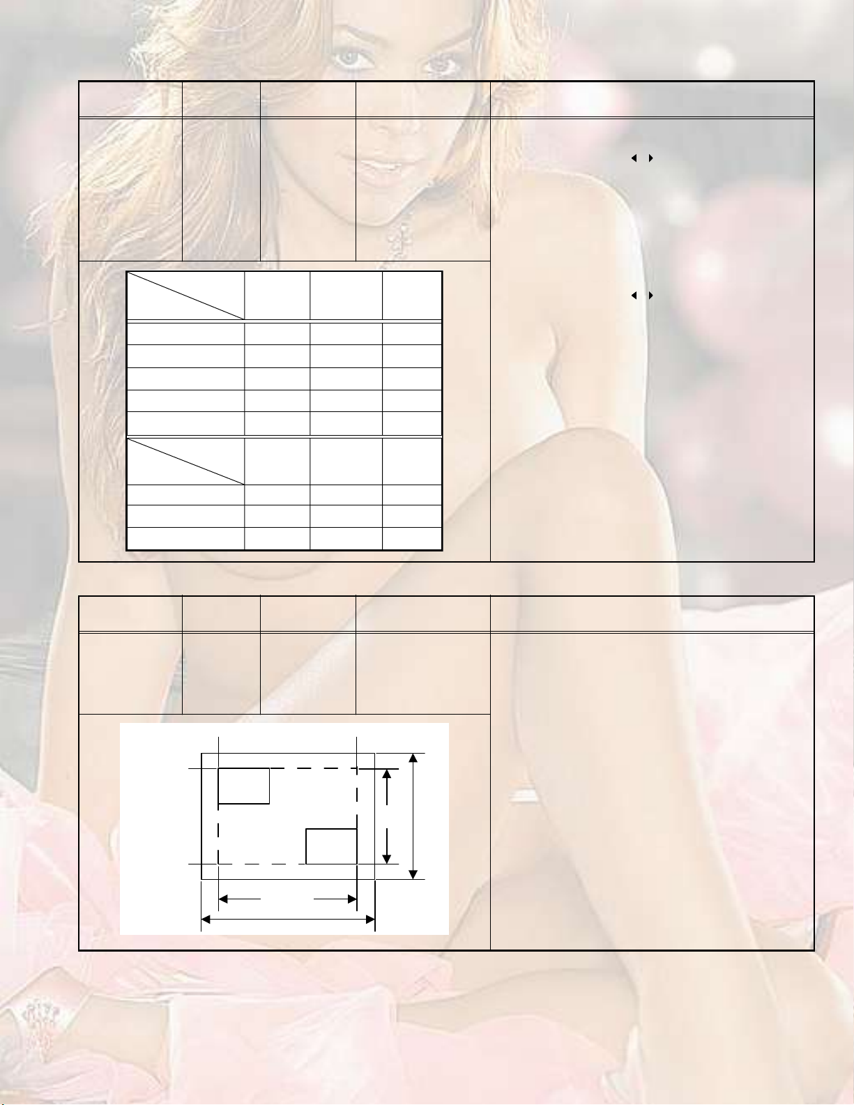
SPECIFICATION
ItemsContents
Dimensions (W I H I D)73.1cm I 62.2cm I 49.4cm
Mass44kg
TV RF SystemB, G, I, D, K, K1, M
Colour SystemPAL / SECAM / NTSC 3.58 / NTSC 4.43
Stereo SystemA2 (B/G, D/K), NICAM (B/G, I, D/K)
Teletext SystemFLOF (Fastext), WST (World Standard System)
Receiving
Frequency
Intermediate
Frequency
Colour Sub
Carrier
Power InputAC110V ~ 240V, 50Hz/60Hz
Power ConsumptionAvg.150W
Picture TubeVisible size : 67.6cm, Measured diagonally H: 55.4cm I V: 41.4cm
High Voltage31.0kV (+1kV / -1.5kV) (at zero beam current)
Speaker6.5cm I 13cm, oval type I 2
Audio Power Output10 W + 10 W (Rated power output)
Aerial Input75 unbalanced, coaxial
Video / Audio
INPUT-1/2/3/4
Video / Audio
Output
Headphone jack3.5 mm stereo mini jack I 1
Remote Control UnitRM-C1351 (UM-3/AA/R6 dry cell battery I 2) [HV-29JH24]
Component Video
625i / 525i / 625p / 525p
VHF Low
VHF High
UHF
CATV
VIF
SIF
PAL
SECAM
NTSC
[INPUT-3]
S-Video
[INPUT-1/4]
Video
Audio
Video
Audio
46.25MHz ~ 168.25MHz
175.25MHz ~ 463.25MHz
471.25MHz ~ 855.25MHz
Mid (X ~ Z+2, S1 ~ S10) / Super (S11 ~ S20) / Hyper (S21 ~ S41) bands
38.0MHz (B, G, I, D, K, L)
32.26MHz (5.74MHz: B), 32.15MHz (5.85MHz: G), 31.45MHz (6.55MHz: I)
31.75MHz (6.25MHz: D), 32.15MHz (5.85MHz: K)
4.43MHz
4.40625MHz / 4.25MHz
3.58MHz / 4.43MHz
RCA pin jack I 3
Y : 1V (p-p), Positive (Negative sync provided), 75
Cb/Cr : 0.7V(p-p), 75
Mini-DIN 4 pin connector I 2
Y: 1V (p-p), Positive (Negative sync provided), 75
C: 0.286V (p-p) (Burst signal), 75
1V (p-p), Positive (Negative sync provided), 75 , RCA pin jack I 4
500mV (rms), High impedance, RCA pin jack I 8
1V (p-p), Positive (Negative sync provided), 75 , RCA pin jack I 1
500mV (rms), Low impedance, RCA pin jack I 2
RM-C1350 (UM-3/AA/R6 dry cell battery I 2) [HV-29JH74/G]
Design and specifications subject to change without notice.
1-2 (No.YA164)
Page 3

SECTION 1
PRECAUTION
1.1SAFETY PRECAUTIONS
(1)The design of this product contains special hardware,
many circuits and components specially for safety
purposes. For continued protection, no changes should be
made to the original design unless authorized in writing by
the manufacturer. Replacement parts must be identical to
those used in the original circuits. Service should be
performed by qualified personnel only.
(2)Alterations of the design or circuitry of the products should
not be made. Any design alterations or additions will void
the manufacturer's warranty and will further relieve the
manufacturer of responsibility for personal injury or
property damage resulting therefrom.
(3)Many electrical and mechanical parts in the products have
special safety-related characteristics. These
characteristics are often not evident from visual inspection
nor can the protection afforded by them necessarily be
obtained by using replacement components rated for
higher voltage, wattage, etc. Replacement parts which
have these special safety characteristics are identified in
the parts list of Service manual. Electrical components
having such features are identified by shading on the
schematics and by ( ) on the parts list in Service
manual. The use of a substitute replacement which does
not have the same safety characteristics as the
recommended replacement part shown in the parts list of
Service manual may cause shock, fire, or other hazards.
(4) Don't short between the LIVE side ground and
ISOLATED (NEUTRAL) side ground or EARTH side
ground when repairing.
Some model's power circuit is partly different in the GND.
The difference of the GND is shown by the LIVE : ( ) side
GND, the ISOLATED (NEUTRAL) : ( ) side GND and
EARTH : ( ) side GND.
Don't short between the LIVE side GND and ISOLATED
(NEUTRAL) side GND or EARTH side GND and never
measure the LIVE side GND and ISOLATED (NEUTRAL)
side GND or EARTH side GND at the same time with a
measuring apparatus (oscilloscope etc.). If above note will
not be kept, a fuse or any parts will be broken.
(5)If any repair has been made to the chassis, it is
recommended that the B1 setting should be checked or
adjusted (See B1 VOLTAGE).
(6)The high voltage applied to the picture tube must conform
with that specified in Service manual. Excessive high
voltage can cause an increase in X-Ray emission, arcing
and possible component damage, therefore operation
under excessive high voltage conditions should be kept to
a minimum, or should be prevented. If severe arcing
occurs, remove the AC power immediately and determine
the cause by visual inspection (incorrect installation,
cracked or melted high voltage harness, poor soldering,
etc.). To maintain the proper minimum level of soft X-Ray
emission, components in the high voltage circuitry
including the picture tube must be the exact replacements
or alternatives approved by the manufacturer of the
complete product.
(7)Do not check high voltage by drawing an arc. Use a high
voltage meter or a high voltage probe with a VTVM.
Discharge the picture tube before attempting meter
connection, by connecting a clip lead to the ground frame
and connecting the other end of the lead through a 10k
2W resistor to the anode button.
(8)When service is required, observe the original lead dress.
Extra precaution should be given to assure correct lead
dress in the high voltage circuit area. Where a short circuit
has occurred, those components that indicate evidence of
overheating should be replaced. Always use the
manufacturer's replacement components.
(9) Isolation Check (Safety for Electrical Shock Hazard)
After re-assembling the product, always perform an
isolation check on the exposed metal parts of the cabinet
(antenna terminals, video/audio input and output terminals,
Control knobs, metal cabinet, screw heads, earphone jack,
control shafts, etc.) to be sure the product is safe to operate
without danger of electrical shock.
a) Dielectric Strength Test
The isolation between the AC primary circuit and all metal
parts exposed to the user, particularly any exposed metal
part having a return path to the chassis should withstand a
voltage of 3000V AC (r.m.s.) for a period of one second. (.
. . . Withstand a voltage of 1100V AC (r.m.s.) to an
appliance rated up to 120V, and 3000V AC (r.m.s.) to an
appliance rated 200V or more, for a period of one second.)
This method of test requires a test equipment not generally
found in the service trade.
b) Leakage Current Check
Plug the AC line cord directly into the AC outlet (do not use
a line isolation transformer during this check.). Using a
"Leakage Current Tester", measure the leakage current
from each exposed metal part of the cabinet, particularly
any exposed metal part having a return path to the chassis,
to a known good earth ground (water pipe, etc.). Any
leakage current must not exceed 0.5mA AC (r.m.s.).
However, in tropical area, this must not exceed 0.2mA AC
(r.m.s.).
Alternate Check Method
Plug the AC line cord directly into the AC outlet (do not
use a line isolation transformer during this check.). Use
an AC voltmeter having 1000 per volt or more
sensitivity in the following manner. Connect a 1500
10W resistor paralleled by a 0.15kF AC-type capacitor
between an exposed metal part and a known good earth
ground (water pipe, etc.). Measure the AC voltage
across the resistor with the AC voltmeter. Move the
resistor connection to each exposed metal part,
particularly any exposed metal part having a return path
to the chassis, and measure the AC voltage across the
resistor. Now, reverse the plug in the AC outlet and
repeat each measurement. Any voltage measured must
not exceed 0.75V AC (r.m.s.). This corresponds to
0.5mA AC (r.m.s.).
However, in tropical area, this must not exceed 0.3V AC
(r.m.s.). This corresponds to 0.2mA AC (r.m.s.).
AC VOLTMETER
(HAVING 1000/V,
OR MORE SENSITIVITY)
0.15F AC-TYPE
PLACE THIS PROBE
1500 10W
GOOD EARTH GROUND
ON EACH EXPOSED
METAL PART
(No.YA164)1-3
Page 4

SECTION 2
SPECIFIC SERVICE INSTRUCTIONS
2.1FEATURES
DigiPure
This function uses the latest in digital technology to give you a
natural-looking picture.
Progressive Scan (525P / 625P signal possible)
This TV can display the Progressive video signal both of 525P
(NTSC) and 625P (PAL) signal.
Cinema Surround
The Cinema Surround function gives you a surround sound
with a "live" effect.
2.2MAIN DIFFERENCE LIST
ItemHV-29JH24HV-29JH74/G
PIP Function NOYES
REMOTE CONTROL UNITRM-C1351-1HRM-C1350-2H
MAIN P.W.BSML-1512A-H2SML-1513A-H2
POWER & DEF P.W.BSML-2505A-H2
CRT SOKET P.W.BSML-3503A-H2
FRONT CONTROL P.W.BSML-8502A-H2
AV JACK P.W.BSML0J505A-H2SML0J506A-H2
MICON/100HZ P.W.BSML0Z504A-H2SML0Z503A-H2
PICTURE MODE
This function can adjust the picture settings automatically.
There are BRIGHT, STANDARD and SOFT in the PICTURE
MODE.
RETURN +
This function can set a channel you frequently view to the
Return Channel and you can view that channel at any time with
one-touch.
1-4 (No.YA164)
Page 5

2.3TECHNINAL INFORMATION
2.3.1MAIN MI-COM (CPU) PIN FUNCTION
Pin
Pin nameI/OFunction
No.
1TCKINot used65D2I/OData bit for PP-RAM/SD-RAM
2TMSINot used66D12I/OData bit for PP-RAM/SD-RAM
3TDIINot used67D10I/OData bit for PP-RAM/SD-RAM
4TDOONot used68VSS33--GND
5P2.8IRemote control 69VDD33i3.3V
6P2.9IKey scan for front control CH+(On: L)70D4I/OData bit for PP-RAM/SD-RAM
7P2.10IKey scan for front control CH- (On: L)71D3I/OData bit for PP-RAM/SD-RAM
8P2.11IKey scan for front control MENU (On: L)72D11I/OData bit for PP-RAM/SD-RAM
9P2.12IReceive data for TV_LINK73RSTINIReset for main CPU
10P2.13OPower on /off control (ON: L)74P3.0I/OData for inter IC control bus
11P2.14I
12P2.15IMain power detection (Normal: H)76P3.2IRemote control
13VSS33--GND77P3.3OPower indication control (On: L)
14VDD33i3.3V78P3.4OAudio muting (Muting: H)
15P4.5/CS3OOutput data for TV_LINK79P3.5OAudio muting (Muting: H)
16P4.4/A20OAddress bit for PP-RAM/SD-RAM80P3.6ONot used
17P4.3/A19OAddress bit for PP-RAM/SD-RAM81P3.7ONot used
18P4.2/A18OAddress bit for PP-RAM/SD-RAM82P3.8I/ONot used
19P4.1/A17OAddress bit for PP-RAM/SD-RAM83P3.9I/ONot used
20VSS25--GND84VSS33--GND
21VDD25I2.5V85VDD33I3.3V
22P4.0/A16OAddress bit for PP-RAM/SD-RAM86VSS25--GND
23A8OAddress bit for PP-RAM/SD-RAM87VDD25I2.5V
24A7OAddress bit for PP-RAM/SD-RAM88TXD0I/ONot used
25A9OAddress bit for PP-RAM/SD-RAM89RXD0I/ONot used
26A6OAddress bit for PP-RAM/SD-RAM90P3.12ONot used
27A5OAddress bit for PP-RAM/SD-RAM91P3.13ONot used
28A10OAddress bit for PP-RAM/SD-RAM92P3.15ONot used
29A11OAddress bit for PP-RAM/SD-RAM93P5.14IRGB input of EXT-2 active
30A12OAddress bit for PP-RAM/SD-RAM94P5.15IHeadphone connection detection (Connect: H)
31VSS33--GND95TRIG_IN--Not used
32VDD33i3.3V96TRIG_OUT--Not used
33A4OAddress bit for PP-RAM/SD-RAM97P6.2ONotifies bus free state (Stop mode: H)
34A3OAddress bit for PP-RAM/SD-RAM98P6.3OClock for inter IC control bus
35A2OAddress bit for PP-RAM/SD-RAM99P6.4I/OData for inter IC control bus
36A1OAddress bit for PP-RAM/SD-RAM100P6.5OMSP reset (Reset: H)
37A0OAddress bit for PP-RAM/SD-RAM101P6.6--Not used
38A13OAddress bit for PP-RAM/SD-RAM102VSYNCIVertical sync
39A14/RASORow address strobe for SD-RAM access103HSYNCIHorizontal sync
40A15/CASOColumn address strobe for SD-RAM access104COR/RSTOUTOOutput for contrast reduction
41VSS33--GND105BLANK/CORBLAOYs for OSD Teletext (blanking)
42VDD33I3.3V106VDD33I3.3V
43MEMCLKOClock for SD-RAM107VSS33--GND
44CSSDRAMOChip select signal for SD-RAM device108XTAL1ISystem clock (4MHz)
45CLKENOEnable for memory clock109XTAL2OSystem clock (4MHz)
46CSROMOChip select signal for PP-ROM device110VSSA--GND
47RDOExternal memory read strobe for PP-ROM111VDDAI2.5V
48UDQMOWrite disable for high byte112RORed for OSD / Teletext
49LDQMOWrite disable for low byte113GOGreen for OSD / Teletext
50WROMemory write strobe114BOBlue for OSD / Teletext
51D15I/OData bit for PP-RAM/SD-RAM115VSSA--GND
52VSS33--GND116VDDA--2.5V
53VDD33I3.3V117CVBS2IComposite video for WSS
54D7I/OData bit for PP-RAM/SD-RAM118VSSA--GND
55D0I/OData bit for PP-RAM/SD-RAM119VDDAI2.5V
56D14I/OData bit for PP-RAM/SD-RAM120CVBS1BIGround for CVBS1A
57D8I/OData bit for PP-RAM/SD-RAM121CVBS1AIComposite video for Teletext decorder
58D6I/OData bit for PP-RAM/SD-RAM122VSSA--GND
59D1I/OData bit for PP-RAM/SD-RAM123VDDAI2.5V
60VSS33--GND124P5.0IAFT voltage for tuner
61VDD33I3.3V125P5.1--Not used
62D13I/OData bit for PP-RAM/SD-RAM126P5.2IAGC voltage for tuner
63D9I/OData bit for PP-RAM/SD-RAM127P5.3--Not used
64D5I/OData bit for PP-RAM/SD-RAM128TMODEITest mode
X-ray HB LB EW correction Protection detection (Normal: H)
Pin
Pin nameI/OFunction
No.
75P3.1I/OData for inter IC control bus
(No.YA164)1-5
Page 6

SECTION 3
DISASSEMBLY
3.1DISASSEMBLY PROCEDURE
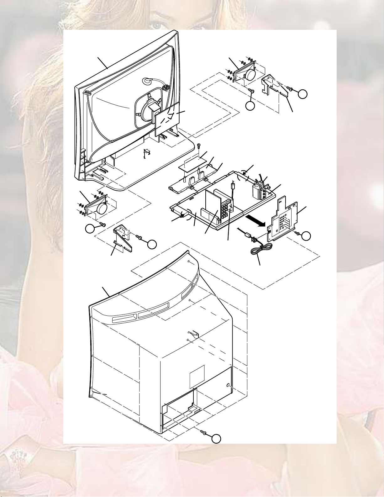
3.1.1REMOVING THE REAR COVER
(1)Unplug the power cord.
(2)Remove the 16 screws [A].
(3)Withdraw the REAR COVER toward you.
3.1.2REMOVING THE AV TERMINAL BOARD
Remove the REAR COVER.
(1)Remove the 5 screws [B].
(2)Withdraw the AV TERMINAL BOARD toward you.
3.1.3REMOVING THE CHASSIS
Remove the REAR COVER.
(1)Slightly raise the both sides of the CHASSIS by hand and
remove the 2 claws under the both sides of the CHASSIS
from the front cabinet.
(2)Withdraw the CHASSIS backward.
(If necessary, take off the wire clamp, connectors etc.)
3.1.4REMOVING THE SPEAKER
Remove the REAR COVER.
(1)Remove the 2 screws [C], then remove the SUPPORT
BRACKET.
(2)Remove the 4 screws [D], then remove the speaker.
(3)Follow the same steps when removing the other
SPEAKER.
3.1.5CHECKING THE PW BOARD
To check the back side of the PW Board.
(1)Pull out the CHASSIS. (Refer to REMOVING THE
CHASSIS).
(2)Remove the CONTROL BASE.
(3)Front side is turned down and a chassis is stood
perpendicularly. The check by the side of the solder side of
MAIN PWB and POWER&DEF PWB is possible.
CAUTION:
When erecting the CHASSIS, be careful so that there will be
no contacting with other PW Board.
Before turning on power, make sure that the wire connector
is properly connected.
When conducting a check with power supplied, be sure to
confirm that the CRT EARTH WIRE (BRAIDED ASS'Y) is
connected to the CRT SOCKET PW board.
3.1.6WIRE CLAMPING AND CABLE TYING
(1)Be sure to clamp the wire.
(2)Never remove the cable tie used for tying the wires
together.
Should it be inadvertently removed, be sue to tie the wires
with a new cable tie.
1-6 (No.YA164)
Page 7
ЪОСТМ ЭЯЮЧТЫМ
НРЫЯХЫО
Ý
НРЫЯХЫО
Ü
НЛРРСОМ ЮОЯЭХЫМ
ОЫЯО ЭСКЫО
ÝÔßÉ
Ý
ЭОМ НСЭХЫМ
РЙЮ
Óß×Ò ÐÉÞ
ßÊ ÍÉ ÐÉÞ
Ü
НЛРРСОМ ЮОЯЭХЫМ
ЪОСТМ ЭСТМОСФшМСРч РЙЮ
ЪОСТМ ЭСТМОСФшЮСММСУч РЙЮ
ЭСТМОСФ ЮЯНЫ
ÝÔßÉ
ÚÞÌ
РСЙЫО ъ ЬЫЪт РЙЮ
ЯК ЮСЯОЬ
Þ
УЧЭСТспррШЖ РЙЮ
РСЙЫО ЭСОЬ
Fig.1
ß
(No.YA164)1-7
Page 8
3.2MEMORY IC REPLACEMENT
This model uses the memory IC.
This memory IC stores data for proper operation of the video and drive circuits.
When replacing, be sure to use an IC containing this (initial value) data.
3.2.1MEMORY IC REPLACEMENT PROCEDURE
1. Power off
Switch off the power and disconnect the power plug from the
AC outlet.
2. Replace the memory IC
Be sure to use the memory IC written with the initial setting
values.
3. Power on
Connect the power plug to the AC outlet and switch on the
power.
4. System constant check and setting
* It must not adjust without signal.
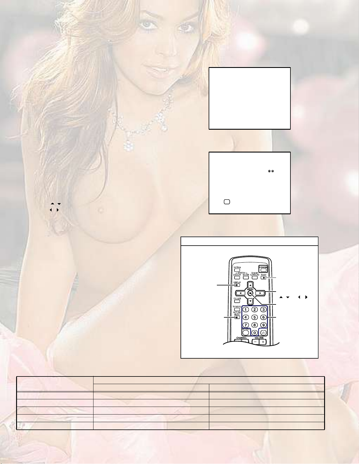
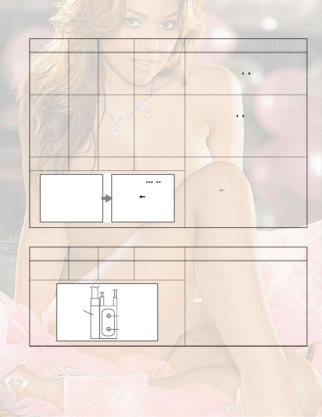
(1)Press the [DISPLAY] key and the [PICTURE MODE] key of
the REMOTE CONTROL UNIT simultaneously.
(2)The SERVICE MODE screen of Fig. 1 will be displayed.
(3)While the SERVICE MODE is displayed, press the
[DISPLAY] key and the [PICTURE MODE] key
simultaneously, and the SYSTEM CONSTANT SET
screen of Fig. 2 will be displayed.
(4)Check the setting values of the SYSTEM CONSTANT
SET. If the value is different, select the setting item with the
[MENU / ] key, and set the correct value with the
[MENU / ] key.
(5)Press the [OK] key to memorize the setting value.
(6)Press the [INFORMATION] key twice, and return to the
normal screen.
5. Receiving channel setting
Refer to the OPERATING INSTRUCTIONS and set the
receive channels (Channels Preset) as described.
6. User settings
Check the user setting items according to the given in page
later.
Where these do not agree, refer to the OPERATING
INSTRUCTIONS and set the items as described.
ЬЧНРФЯЗ µ»§
7. SERVICE MODE setting
Verify what to set in the SERVICE MODE, and set whatever is
necessary (Fig.1).
Refer to the SERVICE ADJUSTMENT for setting.
РЧЭМЛОЫ УСЬЫ
µ»§
НЫОКЧЭЫ УЫТЛ
пт ЧЪ
нт ЯЛЬЧС
лт КНУ РОЫНЫМ
йт РЧР
зт НШЧРРЧТЩшСЪЪч
пуз ж НЫФЫЭМЬЧНР ж ЫИЧМ
от КсЭ
мт ЬЫЪ
кт НМЯМЛН
ит НЛООСЛТЬ
рт ЮЛН ЪОЫЫ
Fig.1
НЗНМЫУ ЭСТНМЯТМ НЫМ
ïò ÌÛÈÌ
ÑÕ
Ü×ÍÐ æ ÛÈ×Ìусх ж НМСОЫ
Fig.2
НЫОКЧЭЫ УЫТЛ
ЖССУ
шЯНРЫЭМч µ»§
ÓÛÒË µ»§
ø ñ ú ñ ÷
ÑÕ µ»§
НЫММЧТЩ ЧМЫУ
НЫФЫЭМ µ»§
шТ«³¾»®- µ»§ч
Fig.3
3.2.2SYSTEM CONSTANT SETTING
Setting item
HV-29JH24HV-29JH74/G
Setting value
1. TEXTYESYES
2. PIPNOYES
3. COLOUR AUTONOYES
4. BLUE BACK MUTENONO
5. TUNERMA1MA1
1-8 (No.YA164)
Page 9

3.2.3SETTINGS OF FACTORY SHIPMENT
3.2.3.1BUTTON OPERATION3.2.3.2REMOTE CONTROL DIRECT OPERATION
Setting itemSetting position
POWEROff
CHANNELPR 1
VOLUME10
TV/VIDEOTV
CHANNELPR1
VOLUME10
ZOOMREGULAR
TV/VIDEOTV
Setting itemSetting position
SLEEP TIMEROFF
DISPLAYIndicated
3.2.3.3REMOTE CONTROL MENU OPERATION
(1) PICTURE SETTING
Setting itemSetting position
PICTURE MODEBRIGHT
CONTRAST / BRIGHT / SHARP
CENTRE
/ COLOUR / HUE
WHITE BALANCEMID
(2) PICTURE FEATURES
Setting itemSetting position
DIGITAL VNR AUTO
DIGIPURE AUTO
PULL DOWN AUTO
COLOUR SYSTEMTVDepend on the preset channel
VIDEOAUTO
ZOOMREGULAR
PICTURE TILTCENTRE
FAVORITE CH CHANNEL
FAVORITE CHANNELCOLOUR
PR01RED
PR02GREEN
(3) SOUND SETTING
Setting itemSetting position
STEREO / I IISTEREO SOUND
BASSCENTRE
TREBLECENTRE
BALANCECENTRE
AI VOLUMEON
CINEMA SURROUNDOFF
(4) FEATURES
Setting itemSetting position
SLEEP TIMEROFF
BLUE BACKON
CHILD LOCKOFF
CAHNNEL GUARDID NO.0000, All CH off
AUTO SHUTOFFOFF
VIDEO-3 SETTINGCOMPONENT
PIP / TWIN [HV-29JH74/G] OFF
SUB INPUT [HV-29JH74/G] VIDEO-1
PIP POSITION [HV-29JH74/G] LOWER LEFT POSITION
PR03YELLOW
PR04BLUE
PICTURE MODEBRIGHT
DIGITAL VNR AUTO
WHITE BALANCEMID
DIGIPURE AUTO
PICTURE EFFECTON
(5) INSTALL
Setting itemSetting position
LANGUAGEENGLISH
AUTO PROGRAMTV channel automatically set
EDIT/MANUALPRESET CH only
TELETEXT LANGUAGEGROUP-1 [HV-29JH74]
GROUP-4 [HV-29JH74/G]
VIDEO SETTING
VIDEO STATUSVIDEO-1, 2, 3, 4
PICTURE MODEBRIGHT
DIGITAL VNR AUTO
WHITE BALANCEMID
DIGIPURE AUTO
PICTURE EFFECTOFF
(No.YA164)1-9
Page 10
3.2.4SERVICE MODE SETTING ITEMS
Setting itemSetting valueSetting itemSetting value
1. IF1. VCO5. VSM PRESETBRIGHT
SOFT
STANDARD
2. V / C1. RGB BLK
2. CUTOFF R
3. CUTOFF G
4. CUTOFF B
5. WDR R
6. STATUS [Do not adjust] 1. SOFT
COOL
WARM
NORMAL
6. WDR G
7. WDR B
7. PIP1. HUE
8. BRIGHT
9. CONT
10. COLOUR
11. HUE
12. SHARP
13. SC ADJ.
14. TOP BLK
15. BTM BLK
16. YUV BRIGHT
17. YUV CONT
18. YUV COLU
19. YUV COLV
20. YUV YDEL
21. YUV UVDEL
22. YCDELM
3. AUDIO1. ERR LIMIT
8. SURROUND1. CH CONFIG
2. A2 ID THR
3. SYSTEM
4. SUB BASS
5. SUB TREBLE
4. DEF1. V-SHIFT
2. V-SIZE
3. H-CENT
4. H-SIZE
5. TRAPEZ
6. EW-PIN
7. COR-UP
8. COR-LO
9. COR-UP-S
10. COR-LO-S
11. ANGLE
12. BOW
13. V-S.CR
14. V-LIN
1. CONT
2. BRIGHT
3. SHARP
4. COLOUR
5. TINT
6. WDR R
7. WDR G
8. WDR B [Do not adjust]
2. EEP MEMORY
2. SC ADJ
3. PIP HORPOS
4. PIP VERPOS
5. YCDELS
2. MATRIX
3. REPRODUCT
4. CENTER MODE
5. SPATIAL EFF
6. VIRTUAL EFF
7. BASS EFFECT
8. HARM
9. HPF
10. LPF
11. AMP LIMIT
12. LEVEL ADJ
13. SWC
14. SW HPF
15. VOLUME
16. HYPER EFF
17. EFFECT MOD
18. HP GAIN
1-10 (No.YA164)
Page 11
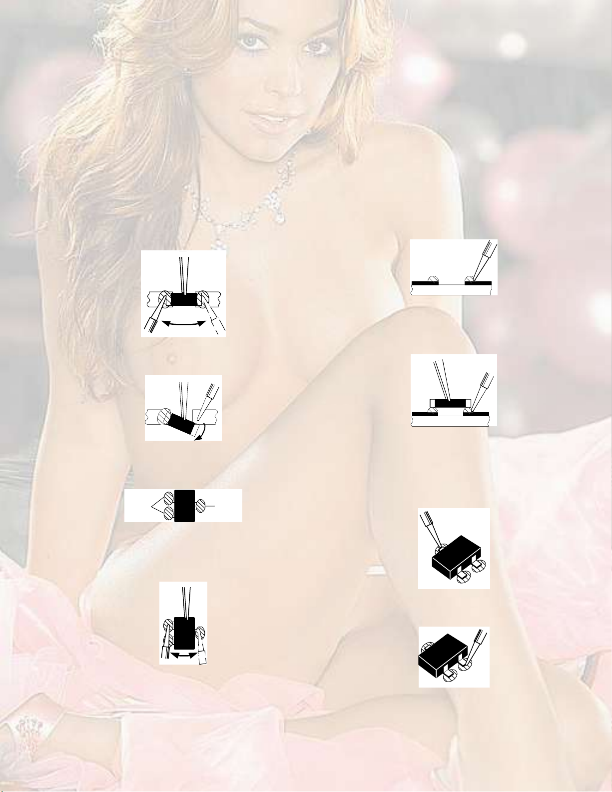
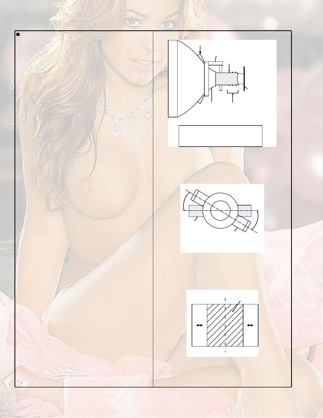
3.3REPLACEMENT OF CHIP COMPONENT
3.3.1CAUTIONS
(1)Avoid heating for more than 3 seconds.
(2)Do not rub the electrodes and the resist parts of the pattern.
(3)When removing a chip part, melt the solder adequately.
(4)Do not reuse a chip part after removing it.
3.3.2SOLDERING IRON
(1)Use a high insulation soldering iron with a thin pointed end of it.
(2)A 30w soldering iron is recommended for easily removing parts.
3.3.3REPLACEMENT STEPS
1. How to remove Chip parts
2. How to install Chip parts
[Resistors, capacitors, etc.]
(1)As shown in the figure, push the part with tweezers and
alternately melt the solder at each end.
(2)Shift with the tweezers and remove the chip part.
[Transistors, diodes, variable resistors, etc.]
(1)Apply extra solder to each lead.
НСФЬЫО
НСФЬЫО
[Resistors, capacitors, etc.]
(1)Apply solder to the pattern as indicated in the figure.
(2)Grasp the chip part with tweezers and place it on the
solder. Then heat and melt the solder at both ends of the
chip part.
[Transistors, diodes, variable resistors, etc.]
(1)Apply solder to the pattern as indicated in the figure.
(2)Grasp the chip part with tweezers and place it on the
solder.
(3)First solder lead A as indicated in the figure.
(2)As shown in the figure, push the part with tweezers and
alternately melt the solder at each lead. Shift and remove
the chip part.
NOTE :
After removing the part, remove remaining solder from the
pattern.
ß
Þ
Ý
(4)Then solder leads B and C.
ß
Þ
Ý
(No.YA164)1-11
Page 12

SECTION 4
ADJUSTMENT
4.1ADJUSTMENT PREPARATION
(1) There are 2 ways of adjusting this TV : One is with the
REMOTE CONTROL UNIT and the other is the
conventional method using adjustment parts and
components.
(2) The adjustment using the REMOTE CONTROL UNIT is
made on the basis of the initial setting values. The
setting values which adjust the screen to the optimum
condition can be different from the initial setting
values.
(3)Make sure that connection is correctly made AC to AC
power source.
(4)Turn on the power of the TV and measuring instruments for
warning up for at least 30 minutes before starting
adjustments.
(5)If the receive or input signal is not specified, use the most
appropriate signal for adjustment.
(6)Never touch the parts (such as variable resistors,
transformers and condensers) not shown in the adjustment
items of this service adjustment.
4.2PRESET SETTING BEFORE ADJUSTMENT
Unless otherwise specified in the adjustment items, preset the
following functions with the REMOTE CONTROL UNIT.
ItemPreset value
PICTURE MODEBRIGHT
CONTRAST / BRIGHT / SHARP / COLOUR / HUECENTRE
WHITE BALANCESTANDARD
DIGITAL VNR AUTO
DIGIPURE AUTO
PULL DOWNAUTO
BASS / TREBLE / BALANCECENTRE
CINEMA SURROUNDOFF
ZOOMREGULAR
PICTURE TILTCENTRE
4.3MEASURING INSTRUMENT AND FIXTURES
(1)DC voltmeter (or digital voltmeter)
(2)Oscilloscope
(3)Signal generator
(Pattern generator : PAL / SECAM / NTSC)
(4)Remote control unit
4.4ADJUSTMENT ITEMS
CHECK ITEMS
B1 POWER SUPPLY check
HIGH VOLTAGE check
IF VCO check
FOCUS
FOCUS adjustment
DEFLECTION CIRCUIT
V. POSITION adjustment
V. SIZE adjustment
H. POSITION adjustment
H. SIZE adjustment
SIDE-PIN adjustment
TRAPEZIUM adjustment
UPPER / LOWER CORNER PIN adjustment
PARALLEL(TILT) adjustment
BOW adjustment
V. S-SHAPE CORRECTION & LINEARITY adjustment
VIDEO CIRCUIT
WHITE BALANCE adjustment
SUB BRIGHT adjustment
SUB CONTRAST adjustment
SUB COLOUR adjustment
SUB HUE adjustment
COLOUR DECODER VCO adjustment
VSM PRESET SETTING
VSM PRESET
PIP SETTING
PIP POSITION adjustment
1-12 (No.YA164)
Page 13
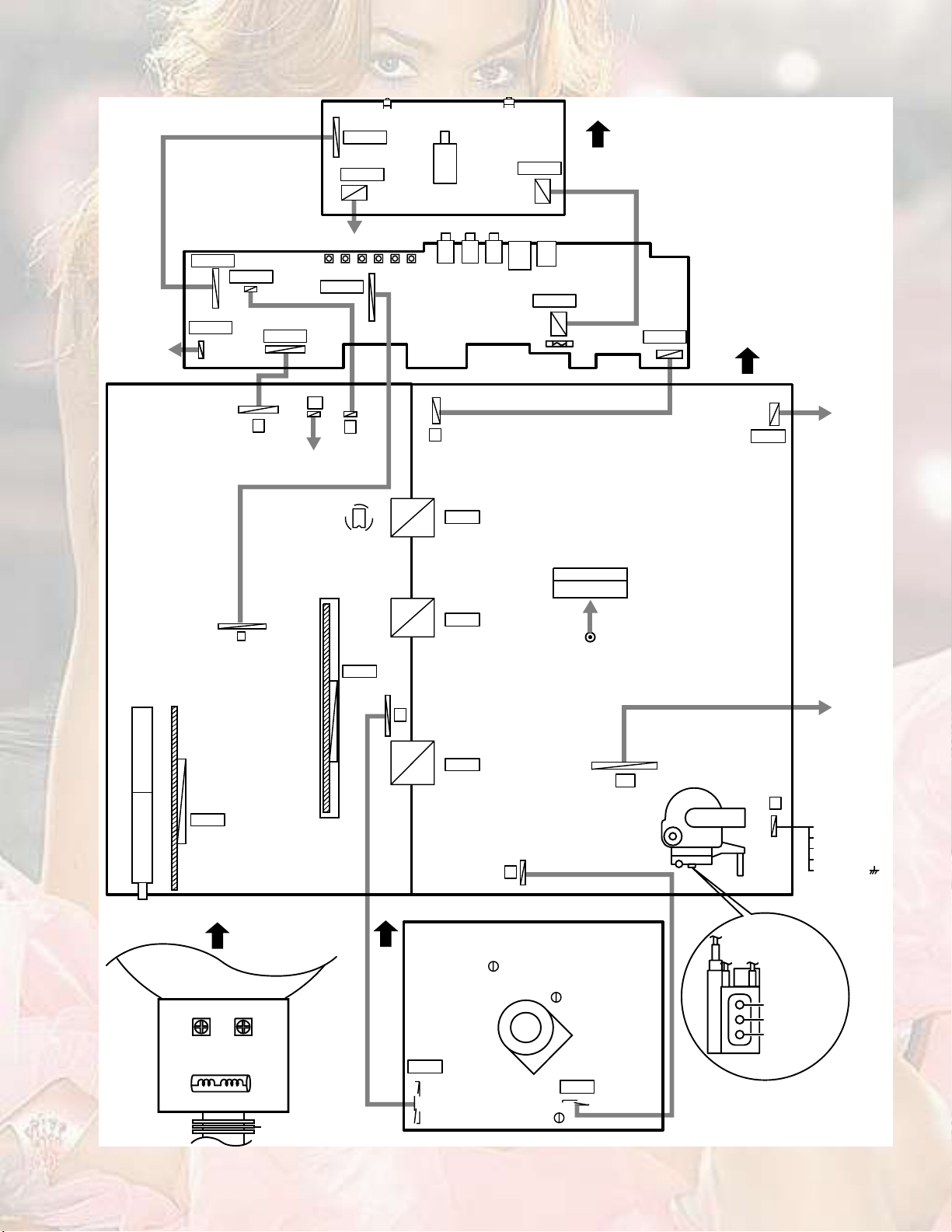
4.5ADJUSTMENT LOCATION
НРЫЯХЫО шФсОч
Óß×Ò ÐÉÞ
ЭТрЦп
ЭТрНР
ЭТррЯ
ЭТррЮ
Þ
ОСМЯМЧСТ ЭСЧФ
ЪОСТМ ЭСТМОСФ РЙЮ шМСРч
ЭТрЦо
ЭТрРЙ
РСЙЫО ЭСОЬ
НиркНирлНирмНирнНироНирп
ЭТррЪ
ÎÌ
ß
УЫУСОЗ ЧЭ
ЧЭйрп
ЪОСТМ ЭСТМОСФ РЙЮ шЮСММСУч
Íçðï
Öèðê
ЦирлЦирм
É
ЭТррн
ЭТрЭо
Öèðí
ЪОСТМ
Öèðï
ЭТрЭп
Úçðï
ЮОЯЧЬЫЬ ЙЧОЫ
ÝÎÌ
ЭТррЙ
ЪОСТМ
ÜÛÙ
РСЙЫО ъЬЫЪ РЙЮ
ÜÛÙ ÝÑ×Ô
МЛТЫО
Ú
ßÊ ÍÉ ÐÉÞ
ЭТррп
УЧЭСУ с пррШ¦
ЪОСТМ
ÝÎÌ
ÈÊ ÝÑ×Ô
ÇÊ
шКОпч
ÇØÝ
шКОоч
ÐÉÞ
ЭТрро
ЭТррм
Î
ЭТррл
ÌÑÐ
ЭОМ НСЭХЫМ РЙЮ
ЭТррО
ÌÐóÛ
ÜÇ
ØÊ
Ù
ÚÞÌ
È
ï
ë
п°·²ж ЮпшМРузпч
о°·²ж ТЭ
н°·²ж ИуОЯЗ
м°·²ж ИуОЯЗ
л°·²ж ЩТЬш ч
шНСФЬЫО НЧЬЫч
МРумйЮ
ЭТррЩ
Ø
Ê
ЪСЭЛН о КО
ЪСЭЛН п КО
НЭОЫЫТ КО
РЭ УЯЩТЫМ
ÌÐóÇ
(No.YA164)1-13
Page 14

4.6BASIC OPERATION OF SERVICE MODE
4.6.1TOOL OF SERVICE MODE OPERATION
Operate the SERVICE MODE with the REMOTE CONTROL UNIT.
4.6.2SERVICE MODE ITEMS
With the SERVICE MODE, various adjustments can be made, and they are broadly classified in the following items of settings.
1.IFThis mode adjusts the setting values of the IF circuit.
2. V/CThis mode adjusts the setting values of the VIDEO circuit.
3.AUDIOThis mode adjusts the setting values of the multiplicity AUDIO circuit.
4. DEFThis mode adjusts the setting values of the DEFLECTION circuit for each aspect mode given below.
5.VSM PRESETThis mode adjusts the initial setting values of BRIGHT, STANDARD and SOFT. (VSM : Video Status Memory)
6.STATUSIt is no requirement to adjustment. [Do not adjust]
7.PIPThis mode adjusts the setting values of the PIP circuit. [HV-29JH74/G only]
8.SURROUNDThis mode adjusts the setting values of the SURROUND circuit.
9.SHIPPINGThis mode is set at shipping setting. [Do no adjust]
0.BUS FREEIt is not requirement to adjustment. [Do no adjust]
4.6.3BASIC OPERATION IN SERVICE MODE
4.6.3.1HOW TO ENTER THE SERVICE MODE
(1)Press the [DISPLAY] key and the [PICTURE MODE] key
simultaneously, then enter the SERVICE MODE.
(2)When the main menu is displayed, press any key of the [0]
to [9] key to enter the corresponding sub menu mode.
4.6.3.2SETTING METHOD
1.IF
[1. VCO] : It must not adjust without signal
(1)[1] key
Select 1.IF.
(2)[1] key
НЫОКЧЭЫ УЫТЛ
пт ЧЪ
нт ЯЛЬЧС
лт КНУ РОЫНЫМ
йт РЧР
зт НШЧРРЧТЩшСЪЪч
пуз ж НЫФЫЭМЬЧНР ж ЫИЧМ
от КсЭ
мт ЬЫЪ
кт НМЯМЛН
ит НЛООСЛТЬ
рт ЮЛН ЪОЫЫ
Select 1.VCO(CW).
Check the arrow position between the ABOVE REF. and
BELOW REF.
(3)[DISPLAY] key
Return to the SERVICE MODE main manu screen.
2. V/C, 4. DEF
(1)[2], [4] key
Select one from 2. V/C, 4. DEF.
Fig.1
НЫОКЧЭЫ УЫТЛ
(2)[MENU / ] key
Select setting items.
(3)[MENU / ] key
Set the setting values of the setting items.
5.VSM PRESET
(1)[5]key
Select 5.VSM PRESET.
(2)[OK] key
Select setting items.
(3)[MENU / ] key
Set the setting values of the setting items.
4.6.3.3MEMORIZE THE ADJUSTMENT DATA
When adjustment is completed, press the [OK] key to memorize
the adjustment value. If not to do it, adjustment data is not
ЬЧНРФЯЗ µ»§
РЧЭМЛОЫ УСЬЫ
µ»§
ЖССУ
шЯНРЫЭМч µ»§
ÓÛÒË µ»§
ø ñ ú ñ ÷
ÑÕ µ»§
Ò«³¾»®- µ»§-
memorized to the memory IC. And if exit the adjustment mode
before memorize the data, the adjustment value which you
change is canceled.
1-14 (No.YA164)
Fig.2
ЕОУуЭпнлрГ
4.6.3.4RELEASE OF SERVICE MODE
After completing the setting, return to the SERVICE MODE, then
again press the [DISPLAY] key.
Page 15
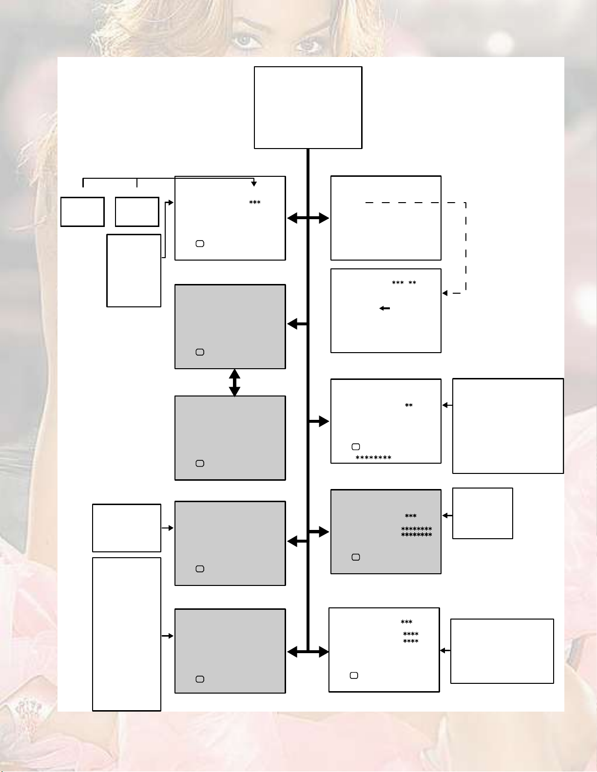
4.6.4SERVICE MODE FLOW CHART
УЯЧТ УЫТЛ НЭОЫЫТ
НЫОКЧЭЫ УЫТЛ
пт ЧЪ
нт ЯЛЬЧС
лт КНУ РОЫНЫМ
йт РЧР
зт НШЧРРЧТЩ шСЪЪч
пуз ж НЫФЫЭМЬЧНР ж ЫИЧМ
от КсЭ
мт ЬЫЪ
кт НМЯМЛН
ит НЛООСЛТЬ
рт ЮЛН ЪОЫЫ
ЭСФСЛО МЫУР
ÝÑÑÔ
ÉßÎÓ
ТСОУЯФ
пт ШЛЫ
от НЭЯЬЦ
нт РЧР ШСОРСН
мт РЧР КЫОРСН
лтЗЭЬЫФН
пт ЭШ ЭСТЪЧЩ
от УЯМОЧИ
нт ОЫРОСЬЛЭМ
мт ЭЫТМЫО УСЬЫ
лт НРЯМЧЯФ ЫЪЪ
кт КЧОМЛЯФ ЫЪЪ
йт ЮЯНН ЫЪЪЫЭМ
ит ШЯОУ
зт ШРЪ
прт ФРЪ
ппт ЯУР ФЧУЧМ
пот ФЫКЫФ ЯЬЦ
пнт НЙЭ
пмт НЙ ШРЪ
плт КСФЛУЫ
пкт ШЗРЫО ЫЪЪ
пйт ЫЪЪЫЭМ УСЬ
пит ШР ЩЯЧТ
РЧЭМЛОЫ УСЬЫ
ЮОЧЩШМ
ÍÑÚÌ
НМЯТЬЯОЬ
пт ЭСТМ
от ЮОЧЩШМ
нт НШЯОР
мт ЭСФСЛО
лт МЧТМ
кт ЙЬО О
йт ЙЬО Щ
ит ЙЬО Ю
лт КНУ РОЫНЫМ
КНУ РОЫНЫМ НМЬ
ïò ÝÑÒÌ
ÑÕ
Ü×ÍÐ æ ÛÈ×Ìусх ж НМСОЫ
кт НМЯМЛН ЕЬ± ²±¬ ¿¼¶«-¬Г
НМЯМЛН
ïò ÍÑÚÌ
ÑÕ
от ЫЫР УЫУСОЗ
ÑÕ
Ü×ÍÐ æ ÛÈ×Ìусх ж НЫФЫМЫ
НМЯМЛН
Ü×ÍÐ æ ÛÈ×Ìусх ж НЫФЫМЫ
éò Ð×Ð Åܱ ²±¬ ¿¼¶«-¬Ã ЕШКуозЦШймсЩГ
Ð×Ð
ïò ØËÛ
ÑÕ
Ü×ÍÐ æ ÛÈ×Ìусх ж НМСОЫ
ит НЛООСЛТЬ ЕЬ± ²±¬ ¿¼¶«-¬Г
НЛООСЛТЬ НжФСЙ
пт ЭШ ЭСТЪЧЩ
ÑÕ
Ü×ÍÐ æ ÛÈ×Ìусх ж НМСОЫ
Fig.3
ïò ×Ú øÝÉ÷
ЧЪ НЫОКЧЭЫ УЫТЛ
ïò ÊÝÑ
Ü×ÍÐ æ ÛÈ×Ìп ж НЫФЫЭМ
КЭСшЭЙч ô Óئ
МСС ШЧЩШ
ЯЮСКЫ ОЫЪ
ЦЛНМ ОЫЪ
ЮЫФСЙ ОЫЪ
МСС ФСЙ
Ü×ÍÐ æ ÛÈ×Ì
îò ÊñÝ
ÊñÝ ÐßÔ
ïò ÎÙÞ ÞÔÕ
ÑÕ
Ü×ÍÐ æ ÛÈ×Ìусх ж НМСОЫ
нт ЯЛЬЧС ЕЬ± ²±¬ ¿¼¶«-¬Г
ЯЛЬЧС
пт ЫОО ФЧУЧМ
ЫЫОСОБФЧУЧМг
ЭБЯЬБЮЧМН г
ÑÕ
Ü×ÍÐ æ ÛÈ×Ìусх ж НМСОЫ
ìò ÜÛÚ
ЬЫЪ ОЫЩЛФЯО Ш¦·
пт КуНШЧЪМ
ÑÕ
ø ÷
Ü×ÍÐ æ ÛÈ×Ìусх ж НМСОЫ
пт ОЩЮ ЮФХ
от ЭЛМСЪЪ О
нт ЭЛМСЪЪ Щ
мт ЭЛМСЪЪ Ю
лт ЙЬО О
кт ЙЬО Щ
йт ЙЬО Ю
ит ЮОЧЩШМ
зт ЭСТМОЯНМ
прт ЭСФСЛО
ппт ШЛЫ
пт ЫОО ФЧУЧМ
от Яо ЧЬ МШО
нт НЗНМЫУ
мт НЛЮ ЮЯНН
лт НЛЮ МОЫЮФЫ
пт КуНШЧЪМ
от КуНЧЖЫ
нт ШуЭЫТМ
мт ШуНЧЖЫ
лт МОЯРЫЖ
кт ЫЙуРЧТ
йт ЭСОуЛР
пот НШЯОР
пнт НЭ ЯЬЦт
пмт МСР ЮФХ
плт ЮМУ ЮФХ
пкт ЗЛК ЮОЧЩШМ
пйт ЗЛК ЭСТМ
пит ЗЛК ЭСФЛ
пзт ЗЛК ЭСФК
орт ЗЛК ЗЬЫФ
опт ЗЛК ЛКЬЫФ
оот ЗЭЬЫФУ
ит ЭСОуФС
зт ЭСОуЛРуН
прт ЭСОуФСуН
ппт ЯТЩФЫ
пот ЮСЙ
пнт КуНтЭО
пмт КуФЧТ
(No.YA164)1-15
Page 16
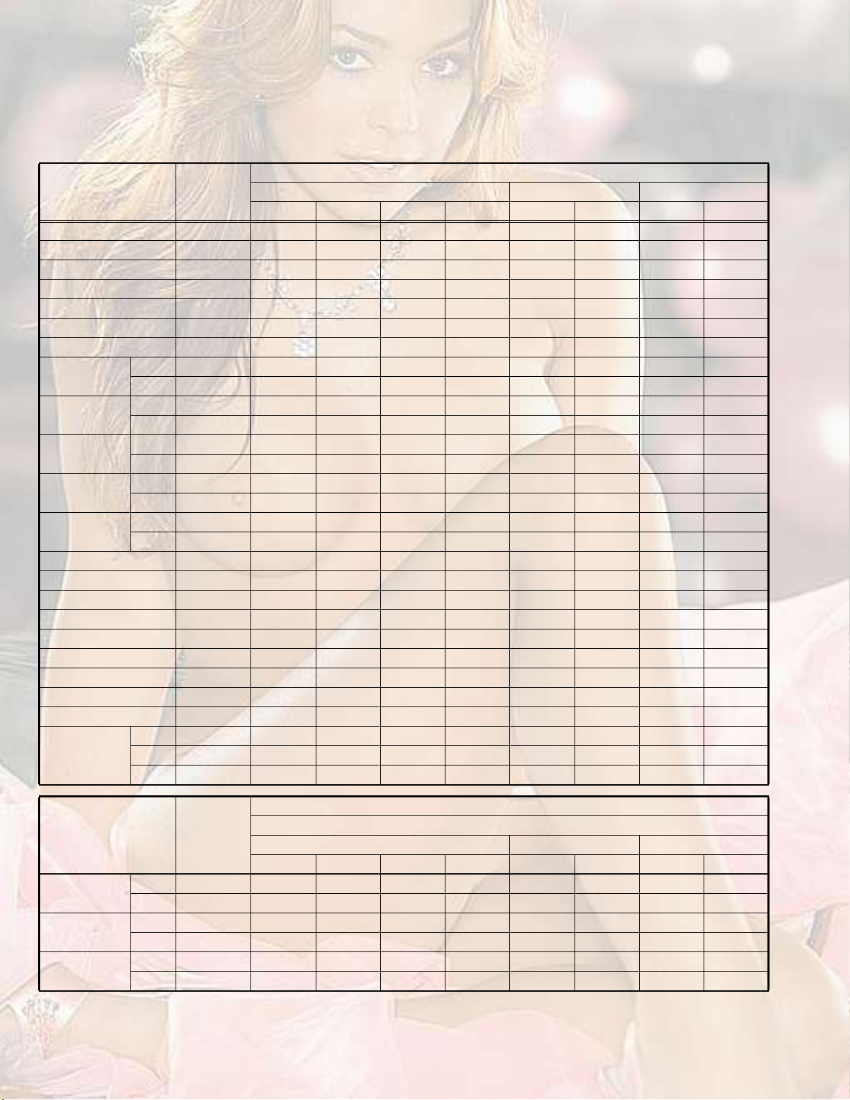
4.7INITIAL SETTING VALUE OF SERVICE MODE
(1)Adjustment of the SERVICE MODE is made on the basis of the initial setting values:however, the new setting values which set
the screen in its optimum condition may differ from the initial setting value.
(2)Do not change the initial setting values of the setting items not listed in "ADJUSTMENT PROCEDURE".
(3)" --- " is impossible to adjustment.
[2. V/C] * is variable values for adjustment.
Setting value
Setting item
Variable
range
RF / Composite Video / S-VideoComponent videoProgressive
PALSECAM
NTSC 3.58NTSC 4.43
50Hz-i60Hz-i50Hz-p60Hz-p
1. RGB BLK---------------------------
2. CUTOFF R0 to 255150*150*150*150*5 5 0 0
3. CUTOFF G0 to 255150*150*150*150*-8 -8 0 0
4. CUTOFF B 0 to 255150 150 150 150 0 0 0 0
5. WDR R0 to 255150*150*150*150*0 0 0 0
6. WDR G0 to 255150*150*150*150*0 0 0 0
7. WDR B 0 to 255150 150 150 150 0 0 0 0
8. BRIGHTRF-128 to 127-25*-25*-25*-25*------------
VIDEO-128 to 127+6 +6 +6 +6 +2 +2 -4 -4
9. CONTRASTRF0 to 6350*50*50*50*------------
VIDEO0 to 63+15 +15 +15 +15 ------------
10. COLOURRF0 to 6336*55*25* 5------------
VIDEO0 to 63-7 -3 -3 0 -14 -5 -10+5
11. HUERF-64 to 63------40 ------------
VIDEO-64 to 63------0 0 ------------
12. SHARP RF-15 to 15-3-3-3-3------------
VIDEO-15 to 150 0 0 0 0 0 0 0
13. SC ADJ0 to 6318*18*18*18*------------
14. TOP BLK 0 to 25535 35 46 46 35 46 51 46
15. BTM BLK -127 to 511-15 -15 -37 -37 -15 -37 -50 -37
16. YUV BRIGHT-64 to 63-------------4-4-4-4
17. YUV CONT0 to 63------------55555555
18. YUV COLU0 to 63------------57 60 0 -10
19. YUV COLV0 to 63------------60 55 0 0
20. YUV YDEL0 to 127------------50 50 30 35
21. YUV UVDEL0 to 127------------49 49 30 35
22. TCDELM RF0 to 1272 0 0 0 ------------
VIDEO0 to 1270 0 0 0 ------------
S-VIDEO
0 to 1271 0 1 1------------
Setting value
Setting item
Variable
range
RF/ Composite Video / S-VideoComponent videoProgressive
PALSECAM
NTSC 3.58NTSC 4.43
Compress (16:9)
50Hz-i60Hz-i50Hz-p60Hz-p
8. BRIGHTRF-128 to 1270 0 0 0 0 0 0 0
VIDEO-128 to 1270 0 0 0 0 0 0 0
9. CONTRASTRF0 to 63-7 -7 -7 -7 ------------
VIDEO0 to 63-7 -7 -7 -7 ------------
10. COLOURRF0 to 630 0 0 0 ------------
VIDEO0 to 630 0 0 0 0 0 0 0
1-16 (No.YA164)
Page 17

[3. AUDIO]
Setting item
1. ERR LIMIT
2. A2 ID THR
3. SYSTEM
4. SUB BASS
5. SUB TREBLE
Variable
range
0000 to 00FF
0000 to 00FF
---
-003 to 0003
-003 to 0003
Setting value
0010
0019
---
0001
0001
[4. DEFLECTION]
Setting value
Setting item
Variable
range
100Hz-i
REGULARZOOM16 : 9
60Hz-p
120Hz-i
50Hz-p
100Hz-i
60Hz-p
120Hz-i
50Hz-p
100Hz-i
60Hz-p
120Hz-i
50Hz-p
1. V-SHIFT-32 to +311-23-200000000
2. V-SIZE-64 to +63-7-1-100000-2700-9
3. H-CENT-128 to +127-16-10-3-20000000
4. H-SIZE-128 to +1278-20-200000000
5. TRAPEZ-63 to +64-40000000200-2
6. EW-PIN-128 to +127-1800000000005
7. COR-UP-64 to +6420000000201-8
8. COR-LO-64 to +64300000002000
9. COR-UP-S-64 to +64100000002002
10. COR-LO-S-64 to +64100000002000
11. ANGLE-128 to +127200000000000
12. BOW-128 to +127100000000000
13. V-S.CR-64 to +631800000000000
14. V-LIN-64 to +63-200-200000000
[5. VSM PRESET]
Setting item
Variable
range
BRIGHTSOFTSTANDARDCOOLWARMNORMAL
Setting value
1. CONT-16 to 1616-20---------
2. BRIGHT-16 to 16-2-20---------
3. SHARP-16 to 160-100---------
4. COLOUR-16 to 160-20---------
5. TINT-16 to 16000---------
6. WDR R-16 to 16----------12220
7. WDR G-16 to 16----------1120
8. WDR B-16 to 16---------000
(No.YA164)1-17
Page 18

[7. PIP] [HV-29JH74/G]
Setting item
1. HUERF
VIDEO
2. SC ADJ
Setting item
(Position display)
3. PIP HOR POS
4. PIP VER POS
Setting item
5. YCDELSRF-016 to 0015-1 -1 -1 -1 ------------
VIDEO-016 to 0015-1 -1 -1 -1 ------------
S-VIDEO-016 to 0015-1 -1 -1 -1 ------------
Variable
range
-128 to 0126
-128 to 0126
0000 to 0063
Variable
range
0000 to 2047
0000 to 1023
Variable
range
RF / Composite Video / S-VideoComponent videoProgressive
PALSECAM
------+4-1 ------------
-------1 -1 ------------
1717171717171717
PAL / SECAM / Component 50Hz-i
Upper leftLower rightUpper leftLower right
222585217585
4719832159
RF / Composite Video / S-VideoComponent videoProgressive
PALSECAM
NTSC 3.58NTSC 4.43
PIP positionPIP position
NTSC 3.58NTSC 4.43
Initial setting value
50Hz-i60Hz-i50Hz-p60Hz-p
Initial setting value
NTSC3.58 / NTSC4.43 /
Component 50Hz-p / 60Hz-i / 60Hz-p
Initial setting value
Regular
50Hz-i60Hz-i60Hz-p60Hz-p
[8. SURROND]
Setting item
1. CH CONFIG
2. MATRIX
3. REPRODUCT
4. CENTER MODE
5. SPATIAL EFF
6. VIRTUAL EFF
7. BASS EFFECT
8. HARM
9. HPF
10. LPF
11. AMP LIMIT
12. LEVEL ADJ
13. SWC
14. SW HPF
15. VOLUME
16. HYPER EFF
17. EFFECT MOD
18. HP GAIN
Variable
range
0000 to 0001
0000 to 0127
0000 to 0015
0000 to 0015
0000 to 0127
0000 to 0127
0000 to 0127
0000 to 0127
0002 to 0030
0005 to 0030
-032 to 0000
-128 to 0012
0005 to 0040
0000 to 0002
0000 to 0003
0000 to 0127
0000 to 0002
0000 to 0008
Initial setting value
LOWHIGH
11
1616
66
33
4050
3547
4652
00
88
1815
-10-15
00
2828
22
33
6363
00
88
1-18 (No.YA164)
Page 19
4.8ADJUSTMENT PROCEDURE
4.8.1CHECK ITEM
Item
B1 VOLTAGE DC voltmeter
Measuring
instrument
X connector
1-pin:TP-E
Remote
control unit
5-pin:TP-91
[POWER DEF
PWB]
HIGH VOLTAGE HV voltmeter
Remote
CRT anode
Chassis GND
control unit
IF VCO Remote
control unit
ЧЪ НЫОКЧЭЫ УЫТЛ
ïò ÊÝÑ
Test pointAdjustment partDescription
[2. V/C]
1. RGB BLK
(1)Receive a any broadcast.
(2)Select 2. V/C from the SERVICE MODE.
(3)Select < 1.RGB BLK >.
(4)Press the [[MENU / ] key to find the cut off
screen (Black screen).
(5)Connect a DC voltmeter to TP-91(B1) and TP-E.
(6)Make sure that the voltage is DC139.9 ±2.0V.
[2. V/C]
1. RGB BLK
(1)Receive a any broadcast.
(2)Select 2. V/C from the SERVICE MODE.
(3)Select < 1. RGB BLK >.
(4)Press the [MENU / ] key to find the cut off screen
(Black screen).
(5)Connect a HV voltmeter to CRT anode and chassis
GND.
(6)Make sure that the voltage is DC31.5kV(+1kV, -1.5kV).
NOTE:
Remove the probe before removing the earth clip.
[1.IF]
1.VCO
Under normal conditions, no adjustment is required.
Confirmation adjustment.
(1)Select 1.IF from the SERVICE MODE.
КЭСшЭЙчфУШ¦
МСС ШЧЩШ
ЯЮСКЫ ОЫЪ
ЦЛНМ ОЫЪ
ЮЫФСЙ ОЫЪ
МСС ФСЙ
(2)Select < 1.VCO >
(3)Receive a any broadcast.
(4)Check the (Arrow) posspition between the ABOVE
REF. and BELLOW REF.
Ü×ÍÐ æ ÛÈ×Ìп ж НЫФЫЭМ
4.8.2FOCUS
Item
Measuring
instrument
FOCUS Signal
generator
ØÊÌ
Ü×ÍÐ æ ÛÈ×Ì
Test pointAdjustment partDescription
FOCUS1 VR
FOCUS2 VR
[In HVT]
(1)Receive the cross hatch signal.
(2)Set the ZOOM mode to REGULAR.
(3)While looking at the screen, adjust the FOCUS VR
to the vertical and horizontal lines will be clear and
infine detail.
(4)Make sure that the picture is in focus even when the
screen gets darkened.
ЪСЭЛН
НЭОЫЫТ
(No.YA164)1-19
Page 20
4.8.3DEFLECTION CIRCUIT
There are 3 aspect modes ( 1. REGULAR, 2. ZOOM, 3. 16 : 9) of the adjustment.
Depending upon the kind of signals ( Vertical frequency 120Hz-i / 100Hz-i / 60Hz-p).
120Hz-i is a signal that is output to a screen when a 60Hz signal is input to a television set. It is an interlace-scanned picture of 120Hz.
100Hz-i is a signal that is output to a screen when a 50Hz signal is input to a television set. It is an interlace-scanned picture of 100Hz.
When the 100Hz mode has been established, the setting of other modes will be done automatically. However, if the picture quality
has not been optimized, adjust each mode again, respectively.
The adjustment using the remote control unit is made on the basis of the initial setting values.
The setting values which adjust the screen to the optimum condition can be different from the initial setting values.
To switch aspect modes, use the [ZOOM] key of the remote controller.
NOTE :
At first the adjustment in 100Hz mode should be done, then the data for the other aspect mode is corrected in the respective value
at the same time. And confirm the deflection adjustment initial setting value in 60Hz (NTSC EXT mode) mode. If the adjustment in
100Hz each aspect mode has been done and stored, the data for the same aspect modes in 60Hz is corrected in the respective
value. Only the data for the other aspect mode in 60Hz is corrected for itself.
Item
V. POSITION Signal
Measuring
instrument
generator
Remote
control unit
Test pointAdjustment partDescription
[4. DEF]
1. V-SHIFT
14. V-LIN
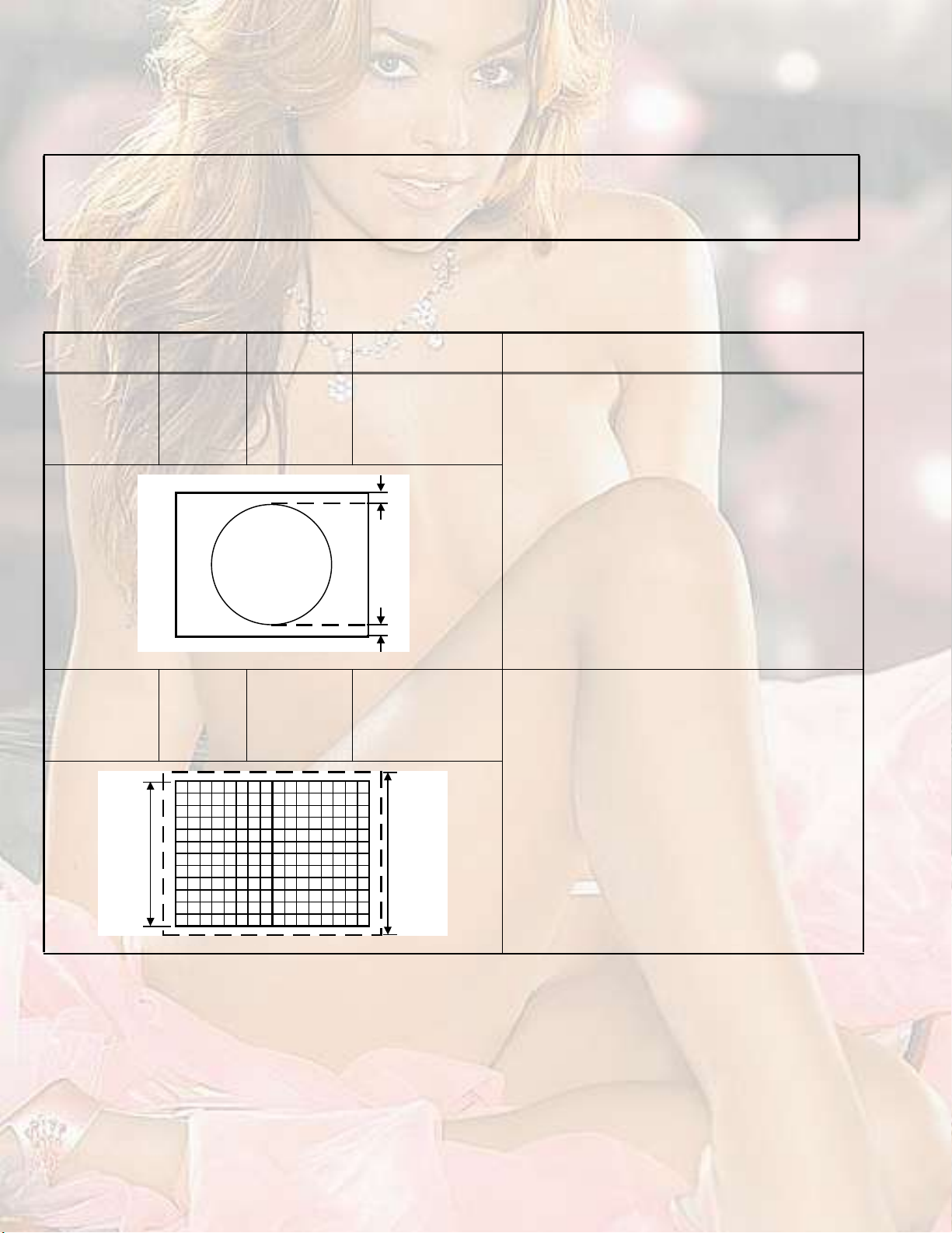
(1)Receive a circle pattern signal of vertical frequency
50Hz (PAL).
(2)Set the ZOOM mode to REGULAR.
(3)Select 4. DEF from the SERVICE MODE.
(4)Select < 1.V-SHIFT >.
(5)Adjust to become A = B.
øß÷
(6)Check the adjustment value above in other zoom
mode. If it is a wrong adjustment, re-adjust in ZOOM
mode and adjust by < 1. V-SHIFT >, < 14.V-LIN >.
(7)Press the [OK] key to memorize the set values.
V. SIZE Signal
generator
Remote
control unit
ͽ®»»²
-·¦»
çíû
øÞ÷
[4. DEF]
2.V-SIZE
з½¬«®»
ïððû
-·¦»
(1)Receive the PAL cross hatch signal.
(2)Set the ZOOM mode to REGULAR.
(3)Select 4. DEF from the SERVICE MODE.
(4)Select < 2.V-SIZE >.
(5)Set the initial setting value of < 2.V-SIZE >.
(6)Adjust to make sure that the vertical screen size of
the picture size is 93%.
(7)Press the [OK] key to memorize the set values.
(8)Input the NTSC VIDEO signal (60Hz) from the EXT
terminal, and make sure that the vertical screen size
is 93%.
(9)Press the [OK] key to memorize the set values.
1-20 (No.YA164)
Page 21
Item
Measuring
instrument
H. POSITION Signal
generator
Remote
control unit
шЯчшЮч
Test pointAdjustment partDescription
[4. DEF]
3.H-CENT.
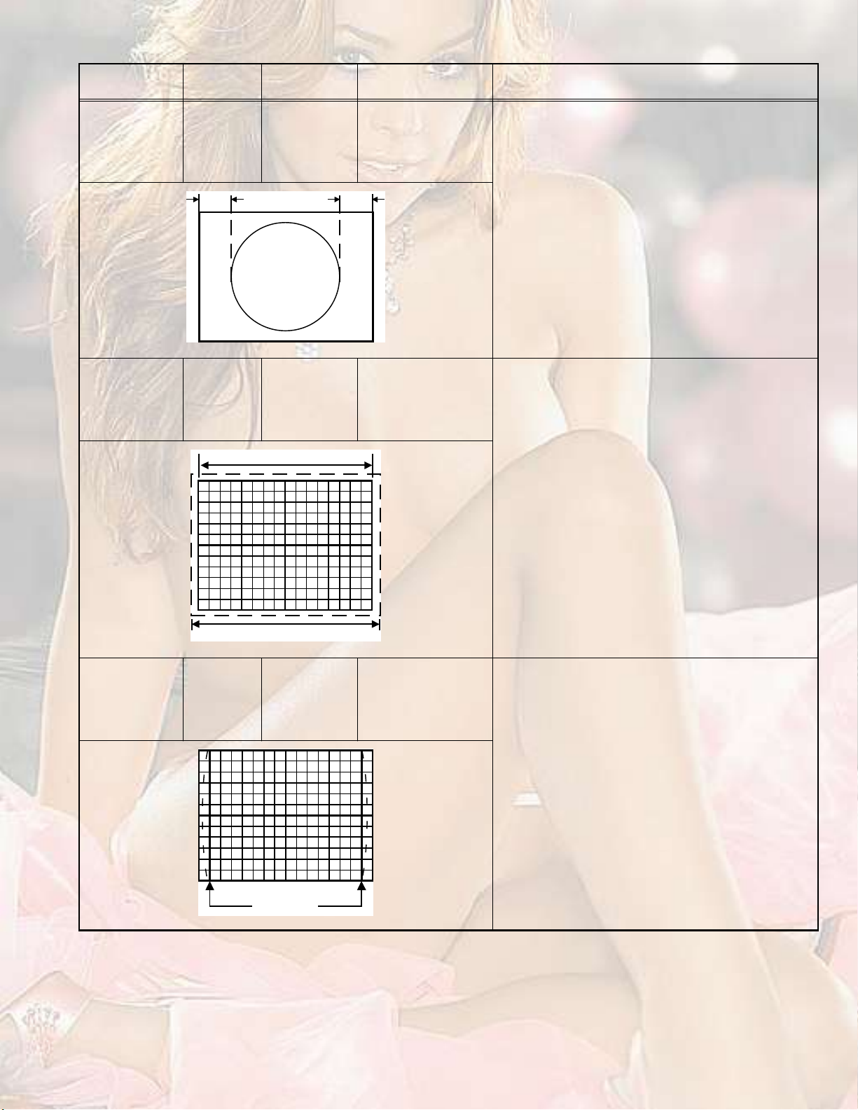
(1)Receive the PAL circle pattern signal.
(2)Set the ZOOM mode to REGULAR.
(3)Select 4. DEF from the SERVICE MODE.
(4)Select < 3.H-CENT. >.
(5)Set the initial setting value of < 3.H-CENT. >.
(6)Adjust to became A=B.
(7)Press the [OK] key to memorize the set values.
H. SIZE Signal
generator
Remote
control unit
SIDE-PIN Signal
generator
Remote
control unit
ͽ®»»² -·¦» çîû
з½¬«®» -·¦» ïððû
[4. DEF]
4.H-SIZE
[4. DEF]
6.EW-PIN
(1)Receive the PAL cross hatch signal.
(2)Set the ZOOM mode to REGULAR.
(3)Select 4. DEF from the SERVICE MODE.
(4)Select < 4.H-SIZE >.
(5)Set the initial setting value of < 4.H-SIZE >.
(6)Adjust to make sure that the horizontal screen size
of the picture size is 92%.
(7)Press the [OK] key to memorize the set value.
(8)Input the NTSC VIDEO signal (60Hz) from the EXT
terminal, and make sure that the horizontal screen
size is 92%.
(9)Press the [OK] key to memorize the set values.
(1)Receive the PAL cross hatch signal.
(2)Set the ZOOM mode to REGULAR.
(3)Select 4. DEF from the SERVICE MODE.
(4)Select < 6.EW-PIN >.
(5)Set the initial setting value of < 6.EW-PIN >.
(6)Adjust to make the vertical lines at the right and left
edges of the screen become straight.
(7)Press the [OK] key to memorize the set values.
ͬ®¿·¹¸¬
(No.YA164)1-21
Page 22
Item
Measuring
instrument
TRAPEZIUM Signal
generator
Remote
control unit
Test pointAdjustment partDescription
[4. DEF]
5.TRAPEZ
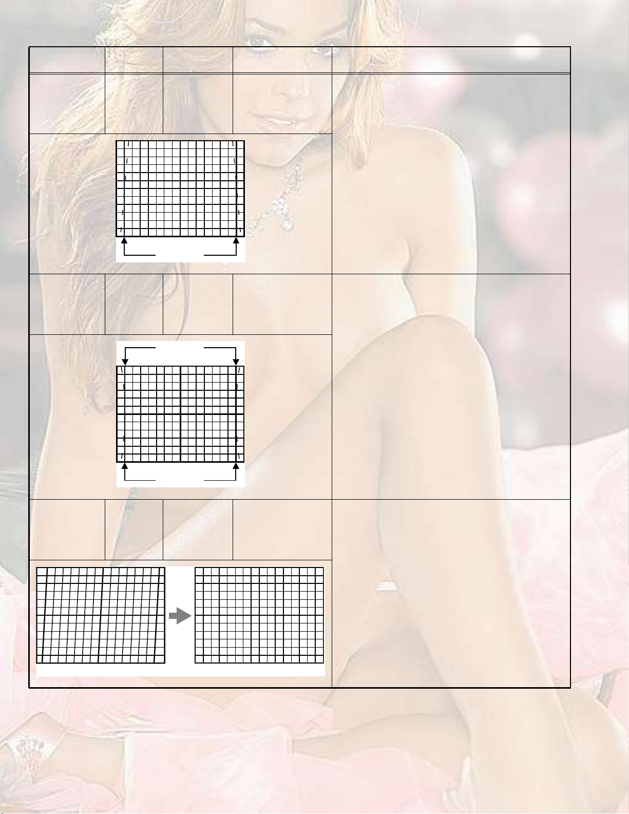
(1)Receive the PAL cross hatch signal.
(2)Set the ZOOM mode to REGULAR.
(3)Select 4. DEF from the SERVICE MODE.
(4)Select < 5.TRAPEZ >.
(5)Set the initial setting value of < 5.TRAPEZ >.
(6)Adjust to bring the vertical lines at the right and left
edges of the screen became parallel.
(7)Press the [OK] key to memorize the set values.
п®¿´´»´
UPPER/LOWER
CORNER PIN
PARALLEL
(TILT)
Signal
generator
Remote
control unit
Signal
generator
Remote
control unit
ͬ®¿·¹¸¬
ͬ®¿·¹¸¬
[4. DEF]
7.COR-UP
8.COR-LO
9.COR-UP-S
10.COR-LO-S
[4. DEF]
11.ANGLE
(1)Receive the PAL cross hatch signal.
(2)Set the ZOOM mode to REGULAR.
(3)Select 4. DEF from the SERVICE MODE.
(4)Select < 8. COR-LO >.
(5)Set the initial setting value of < 8. COR-LO >.
(6)Adjust to bring the straight line at the lower corner.
(7)Select < 7. COR-UP >.
(8)Set the initial setting value of < 7. COR-UP >.
(9)Adjust to bring the straight line at the upper corner.
(10)Adjust < 8. COR-LO > and < 7. COR-UP > so that
the vertical lines at the four corners on the screen
are straight.
(11)If the extreme upper & lower corners are little pin or
barrel, chose < 9. COR-UP-S >, < 10. COR-LO-S >
and adjust to get straight.
(12)Press the [OK] key to memorize the set values.
(1)Receive the PAL cross hatch signal.
(2)Set the ZOOM mode to REGULAR.
(3)Select 4. DEF from the SERVICE MODE.
(4)Select < 11. ANGLE >.
(5)Adjust to bring the vertical lines straight.
(6)Press the [OK] key to memorize the set values.
1-22 (No.YA164)
Bring the vertical lines straight.
Page 23
Item
Measuring
instrument
BOW Signal
generator
Remote
control unit
Test pointAdjustment partDescription
[4. DEF]
12. BOW
(1)Receive the PAL cross hatch signal.
(2)Set the ZOOM mode to REGULAR.
(3)Select 4. DEF from the SERVICE MODE.
(4)Select < 12.BOW >.
(5)Adjust to bring the vertical lines straight.
(6)Press the [OK] key to memorize the set values.
Bring the vertical lines straight.
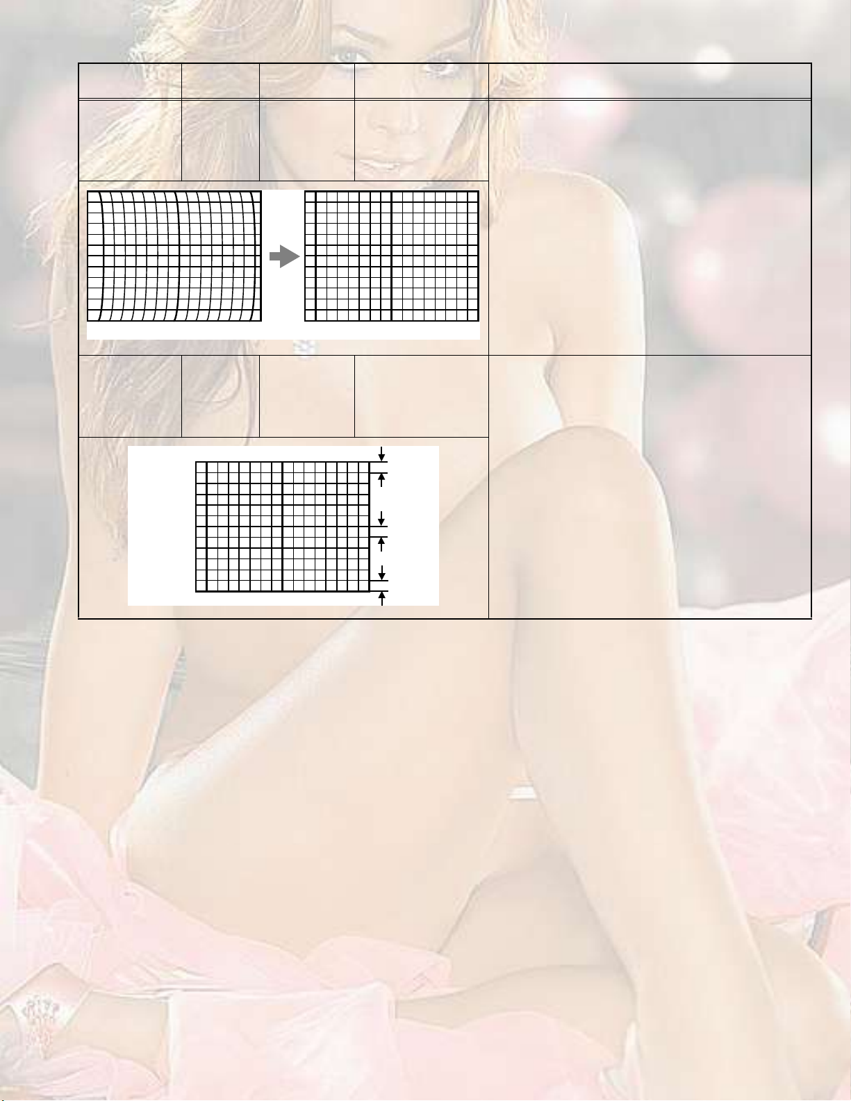
V. S-SHAPE
CORRECTION &
LINEARITY
Signal
generator
Remote
control unit
[4. DEF]
13. V-S. CR
14. V-LIN
ÌÑÐ
ÌÑÐ
ЮСММСУ
When the vertical linearity has been deteriorated
remarkably, perform the following steps.
(1)Receive the PAL cross hatch signal.
(2)Set the ZOOM mode to REGULAR.
(3)Select 4. DEF from the SERVICE MODE.
(4)Select < 14. V-LIN >.
(5)Set the initial setting value of < 14. V-LIN >.
(6)Select < 13. V-S.CR >.
(7)Set the initial setting value of < 13. V-S.CR >.
(8)Adjust < 14. V-LIN > and < 13. V-S.CR > so that the
spaces of each line on TOP, CENTER and
BOTTOM become uniform.
(9)Press the [OK] key to memorize the set values.
(No.YA164)1-23
Page 24
4.8.4VIDEO CIRCUIT
Item
WHITE BALANCE
Measuring
instrument
Signal
generator
Remote
control unit
SUB BRIGHT Remote
control unit
SUB CONTRAST Remote
control unit
Test pointAdjustment partDescription
[2. V/C]
2.CUTOFF R
3.CUTOFF G
4.CUTOFF B
5.WDR R
6.WDR G
(1)Receive a black and white signal (colour off).
(2)Set the ZOOM mode to REGULAR.
(3)Set the PICTURE MODE to STANDARD.
(4)Set the WHITE BALANCE to MID.
(5)Select 2. V/C from the SERVICE MODE.
(6)Select < 2.CUTOFF R >, < 3.CUTOFF G > and
< 4.CUTOFF B >.
(7)Adjust the screen until the black portion in the screen
becomes black.(Low light)
(8)Select < 5.WDR R > and < 6.WDR G >.
(9)Adjust the screen until the white portion in the screen
becomes white (High light).
(10)Press the [OK] key to memorize the set values.
(11)Change the contrast and brightness with the remote
control up & down from low-light to high-light and
check that the tracking of the white balance is good.
[2. V/C]
8. BRIGHT
(1)Receive any broadcast.
(2)Set the ZOOM mode to REGULAR.
(3)Set the PICTURE MODE to STANDARD.
(4)Set the WHITE BALANCE to MID.
(5)Select 2. V/C from the SERVICE MODE.
(6)Select < 8. BRIGHT >.
(7)Set the initial setting value of < 8.BRIGHT >.
(8)If the brightness is not the best with the initial setting
value, make fine adjustment until you get the best
brightness.
(9)Press the [OK] key to memorize the set values.
[2. V/C]
9. CONTRAST
(1)Receive any broadcast.
(2)Set the ZOOM mode to REGULAR.
(3)Set the PICTURE MODE to STANDARD.
(4)Set the WHITE BALANCE to MID.
(5)Select 2. V/C from the SERVICE MODE.
(6)Select < 9.CONTRAST >.
(7)Set the initial setting value of < 9.CONTRAST >.
(8)If the contrast is not the best with the initial setting
value, make fine adjustment until you get the best
contrast.
(9)Press the [OK] key to memorize the set values.
1-24 (No.YA164)
Page 25
Item
Measuring
instrument
SUB COLOUR Signal
generator
Remote
control unit
Signal
generator
Oscilloscope
Remote
control unit
É Ý
Test pointAdjustment partDescription
TP-47B
TP-E
[CRT SOCKET PWB]
ÇÙÎ
Þ
Ó
[2. V/C]
10.COLOUR
[2. V/C]
10.COLOUR
øó÷
øß÷
ð
øõ÷
[Method of adjustment without measuring instrument]
PAL COLOUR
(1)Receive the PAL broadcast.
(2)Set the ZOOM mode to REGULAR.
(3)Set the PICTURE MODE to STANDARD.
(4)Set the WHITE BALANCE to MID.
(5)Select 2. V/C from the SERVICE MODE.
(6)Select < 10.COLOUR >.
(7)Set the initial setting value of < 10.COLOUR >.
(8)If the colour is not the best with the initial set value,
make fine adjustment until you get the best colour.
(9)Press the [OK] key to memorize the set values.
SECAM COLOUR :
(1)Receive the SECAM broadcast.
(2)Follow the same step 2 to 9 as in PAL COLOUR.
NTSC 3.58 COLOUR :
(1)Receive the NTSC broadcast.
(2)Follow the same step 2 to 9 as in PAL COLOUR.
NTSC 4.43 COLOUR :
When NTSC 3.58 COLOUR set, NTSC 4.43
COLOUR will automatically set.
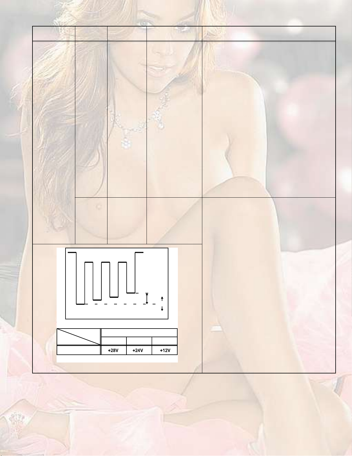
[Method of adjustment using measuring instrument]
PAL COLOUR
(1)Receive the PAL full field colour bar signal (75%
white).
(2)Connect the oscilloscope between TP-47B and TP-E.
(3)Set the ZOOM mode to REGULAR.
(4)Set the PICTURE MODE to STANDARD.
(5)Set the WHITE BALANCE to MID.
(6)Select 2. V/C from the SERVICE MODE.
(7)Select < 10.COLOUR >.
(8)Set the initial setting value of < 10.COLOUR >.
(9)Adjust the value of (A) to the value in the voltage
table in the left.
(10)Press the [OK] key to memorize the set values.
SECAM COLOUR
(1)Receive the SECAM colour bar signal (75% white).
(2)Follow the same step 2 to 10 as in PAL COLOUR.
КСФМЯЩЫ шЙуЮч
ʱ´¬¿¹» -»¬¬·²¹
РЯФНЫЭЯУТМНЭ
ʱ´¬¿¹» ¬¿¾´»
NTSC 3.58 COLOUR
(1)Input the NTSC 3.58MHz full field colour bar signal
(75% white).
(2)Follow the same step 2 to 10 as in PAL COLOUR.
NTSC 4.43 COLOUR
When NTSC 3.58 COLOUR set, NTSC 4.43
COLOUR will automatically set.
(No.YA164)1-25
Page 26
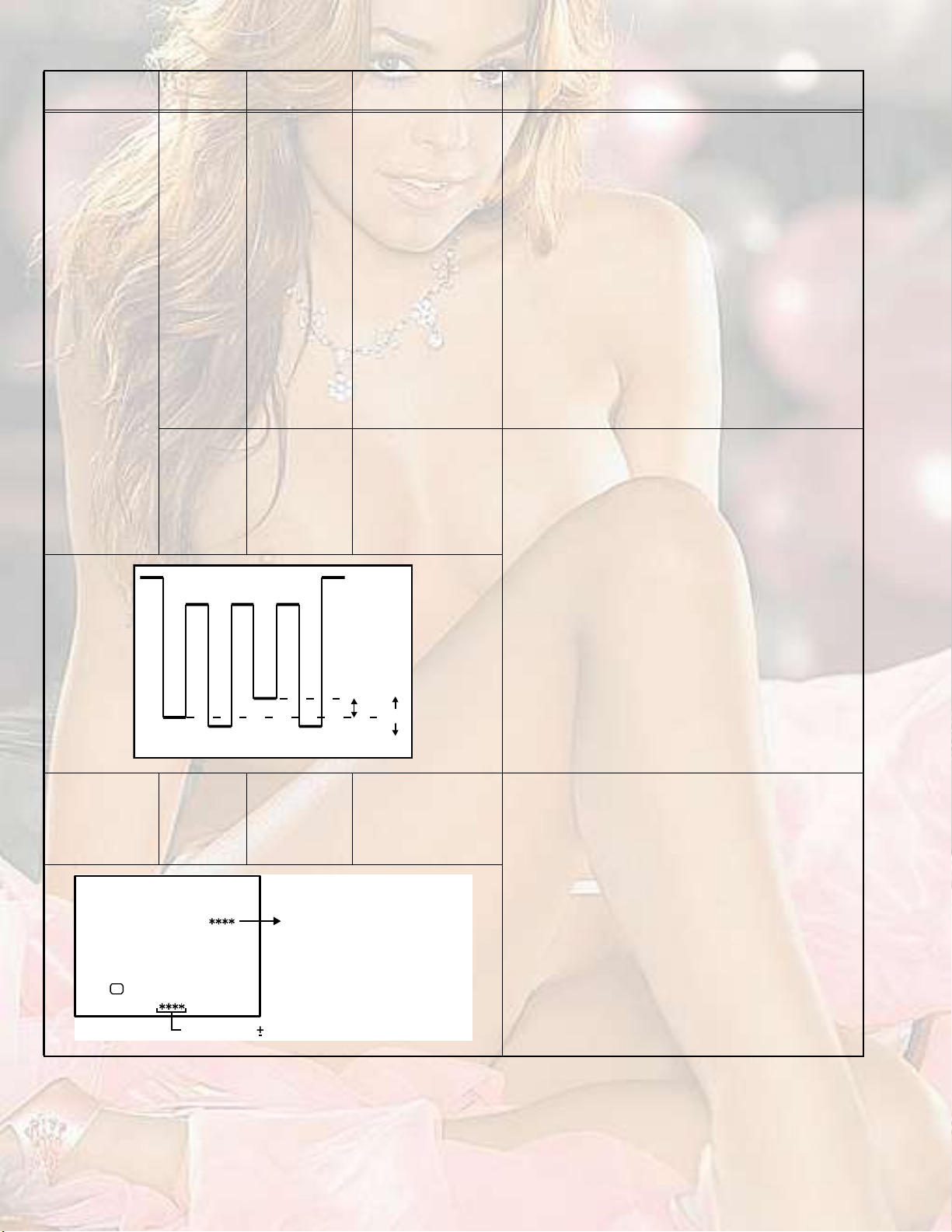
Item
Measuring
instrument
SUB HUE Signal
generator
Remote
control unit
Signal
generator
Oscilloscope
Remote
control unit
É Ý
Test pointAdjustment partDescription
TP-47B
TP-E
[CRT SOCKET PWB]
ÇÙÎ
Ó
Þ
[2. V/C]
11.HUE
[2. V/C]
11.HUE
øó÷
øÞ÷
ð
øõ÷
[Method of adjustment without measuring instrument]
NTSC 3.58 HUE
(1)Input the NTSC 3.58MHz full field colour bar signal
(75% white).
(2)Set the ZOOM mode to REGULAR.
(3)Set the PICTURE MODE to STANDARD.
(4)Set the WHITE BALANCE to MID.
(5)Select 2. V/C from the SERVICE MODE.
(6)Select < 11.HUE >.
(7)Set the initial setting value of < 11.HUE >.
(8)If you cannot get the best HUE with the initial setting
value, make fine adjustment until you get the best
HUE.
(9)Press the [OK] key to memorize the set values.
NTSC 4.43 HUE
When NTSC 3.58 COLOUR set, NTSC 4.43
COLOUR will automatically set.
[Method of adjustment using measuring instrument]
NTSC 3.58 HUE
(1)Input the NTSC 3.58MHz full field colour bar signal
(75% white).
(2)Set the ZOOM mode to REGULAR.
(3)Set the PICTURE MODE to STANDARD.
(4)Set the WHITE BALANCE to MID.
(5)Select 2. V/C from the SERVICE MODE.
(6)Select < 11.HUE >.
(7)Set the initial setting value of < 11.HUE >.
(8)Connect the oscilloscope between TP-47B and TP-E.
(9)Adjust NTSC 3.58 HUE and bring the value of (B) in
the illustration to -13V.
(10)Press the [OK] key to memorize the set values.
NTSC 4.43 HUE
When NTSC 3.58 COLOUR set, NTSC 4.43
COLOUR will automatically set.
COLOUR
DECODER VCO
ÊñÝ ÐßÔ
ïíò ÍÝ ßÜÖò
ÑÕ
НЭ ЬЫКЪЛФФ
1-26 (No.YA164)
Signal
generator
Remote
control unit
Ü×ÍÐ æ ÛÈ×Ìусх ж НМСОЫ
Ù»¬ ·² ðððð ðððí
[2. V/C]
13.SC ADJ
É·¬¸·² ðððé¢ððîì ¿¼¶«-¬³»²¬ò
(1)Receive the PAL full field colour bar signal (75%
white).
(2)Set the ZOOM mode to REGULAR.
(3)Set the PICTURE MODE to STANDARD.
(4)Set the WHITE BALANCE to MID.
(5)Select 2. V/C from the SERVICE MODE.
(6)Select < 13. SC ADJ >.
(7)Adjust the value "SC DEV" indicated below of screen
get in 0000±0003. "SC DEV" should be adjusted
within 0007 to 0024.
(8)Press the [OK] key to memorize the set values.
Note :
When the [OK] key is pressed, VCO for colour decoder
will be automatically set at the respective values.
Page 27
4.8.5VSM PRESET SETTING
Item
Measuring
instrument
VSM PRESET Remote
control unit
ïò ÝÑÒÌ ïêð
от ЮОЧЩШМ óîð
нт НШЯОР ðð
мт ЭСФСЛО ðð
ëò Ì×ÒÌ ð
Test pointAdjustment partDescription
[5.VSM PRESET]
1.CONT.
2.BRIGHT
3.SHARP
4.COLOUR
5.TINT
6.WDR R
7.WDR G
8.WDR B
(1)Select 5.VSM PRESET from the SERVICE MODE.
(2)Select the BRIGHT with the [OK] key.
(3)Adjust the [MENU / ] key to bring the set values
of < 1.CONT > - < 5.TINT > to the values shown in
the table.
(4)Press the [OK] key to memorize the set values.
(5)Select the STANDARD with the [OK] key.
(6)Repeat the steps 3. to 4. as above.
(7)Select the SOFT with the [OK] key.
(8)Repeat the steps 3. to 4. as above.
(9)Select COOL with the [OK] key.
ЮОЧЩШМНМЯТЬЯОЬНСЪМ
(10)Adjust the [MENU / ] key to bring the set values
of < 6.WDR R > to < 8.WDR B > to the values shown
óî
óî
óïð
óî
ð
ð
in the table.
(11)Press the [OK] key to memorize the set values.
(12)Select COOL with the [OK] key.
(13)Repeat the steps 10. to 11. as above.
(14)Select WARM with the [OK] key.
(15)Repeat the steps 10. to 11. as above.
(16)Select NORAML with the [OK] key.
(17)Repeat the steps 10. to 11. as above.
ЭССФЙЯОУТСОУЯФ
ïò ÉÜÎ Î упооор
îò ÉÜÎ Ù îóïïð
íò ÉÜÎ Þ ððð
4.8.6PIP SETTING [HV-29JH74/G]
Item
Measuring
instrument
PIP POSITION Signal
generator
Remote
control unit
LEFT POS.
UPPER POS.
LOWER POS.
PIP
screen
80% ±2%
Test pointAdjustment partDescription
[7. PIP]
3. PIP HORPOS
4. PIP VERPOS
Proceed to the following adjustment after having
completed the adjustments of DEFLECTION circuit.
PAL PIP POSITION
(1)Receive the PAL colour bar signal for Main screen
and input the PAL cross hatch signal for PIP screen.
RIGHT POS.
(2)Set the ZOOM mode to REGULAR.
(3)Select 7. PIP from the SERVICE MODE.
(4)Select < 3. PIP HORPOS > and < 4. PIP VERPOS >.
(5)Adjust the left upper position of PIP screen is roughly
shown in a left figure.
NTSC PIP POSITION
(1)Receive the NTSC colour bar signal for Main screen
and input the NTSC cross hatch signal for PIP
screen.
PIP
screen
80%
±2%
Main
screen
size
(2)Follow the same step 2 to 5 as in PAL POSITION.
Main screen size
(No.YA164)1-27
Page 28
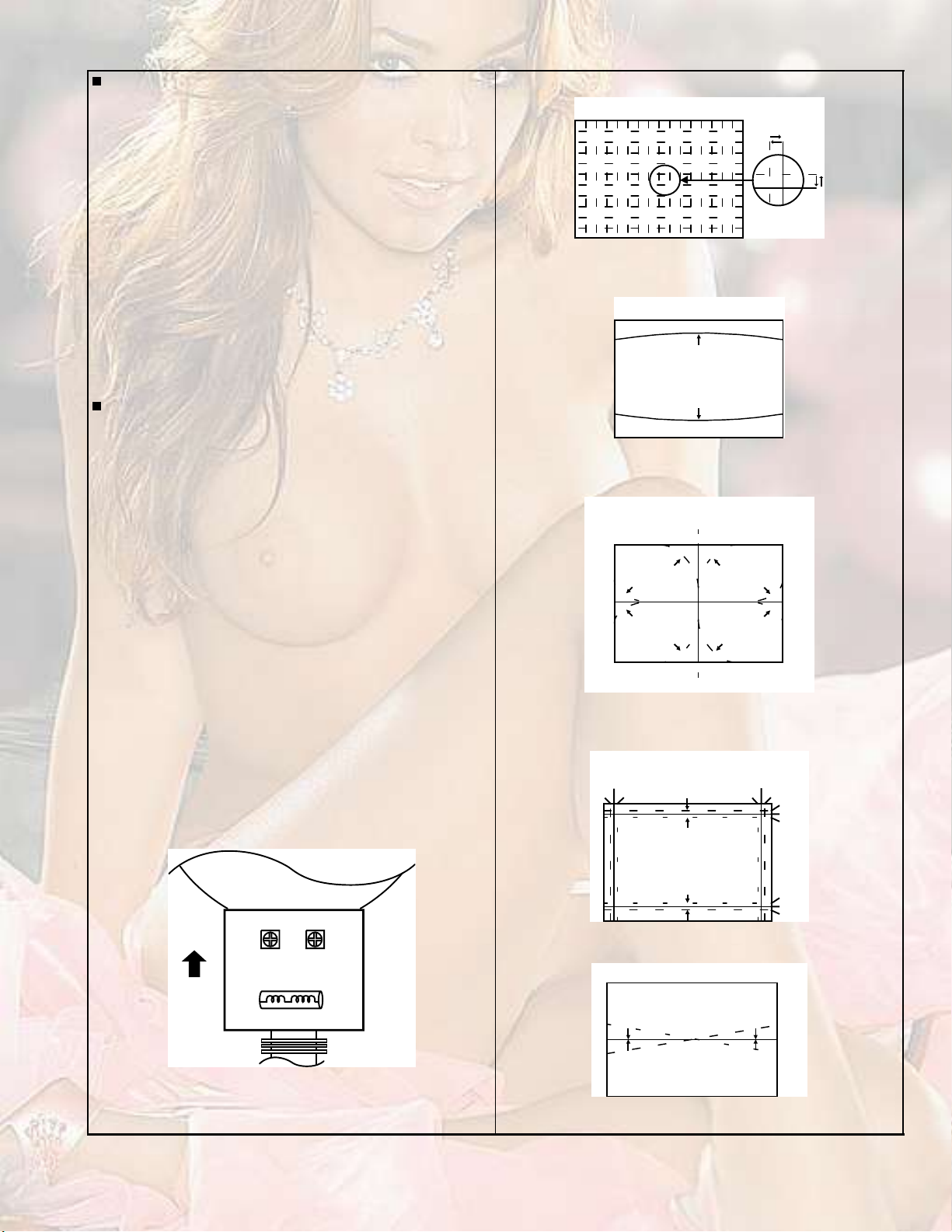
4.8.7PURITY AND CONVERGENCE
PURITY ADJUSTMENT
(1)Demagnetize CRT with the demagnetizer.
(2)Loosen the retainer screw of the deflection yoke.
(3)Remove the wedges.
ЙЫЬЩЫ
ЬЗТЯУЧЭ ЭСТКЫОЩЫТЭЫ
ЯЬЦЛНМУЫТМ
РЛОЧМЗ УЯЩТЫМшРч
(4)Input a green raster signal from the signal generator, and
turn the screen to green raster.
(5)Move the deflection yoke backward.
(6)Bring the long lug of the purity magnets on the short lug and
position them horizontally. (Fig.2)
(7)Adjust the gap between two lugs so that the GREEN
RASTER will come into the center of the screen. (Fig.3)
(8)Move the deflection yoke forward, and fix the position of the
deflection yoke so that the whole screen will become green.
(9)Insert the wedge to the top side of the deflection yoke so that
it will not move.
(10)Input a crosshatch signal.
(11)Verify that the screen is horizontal.
(12)Input red and blue raster signals, and make sure that purity
is properly adjusted.
ÝÎÌ
ìê
ЭОМ НСЭХЫМ РЙЮ
ÜÛÚò ÇÑÕÛ
РсЭ УЯЩТЫМН
РсЭ УЯЩТЫМН
Ð æ
РЛОЧМЗ
УЯЩТЫМ
м ж м РСФЫН ш½±²ª»®¹»²½» ³¿¹²»¬ч
к ж к РСФЫН ш½±²ª»®¹»²½» ³¿¹²»¬ч
Fig.1
PURITY MAGNETS
Short lug
Long lug
Bring the long lug over the short lug and
position them horizontally.
Fig.2
( FRONT VIEW )
GREEN RASTER
CENTER
Fig.3
1-28 (No.YA164)
Page 29
PURITY ADJUSTMENT
(1)Input a crosshatch signal.
(2)Using 4-pole convergence magnets, overlap the red and
blue lines in the center of the screen (Fig.1) and turn them
to magenta (red/blue).
(3)Using 6-pole convergence magnets, overlap the magenta
(red/blue) and green lines in the center of the screen and
turn them to white.
(4)Repeat 2 and 3 above, and make best convergence.
After adjustment, fix the wedge at the original position.Fasten
the retainer screw of the deflection yoke.Fix the 6 magnets with
glue.
DYNAMIC (periphery) CONVERGENCE ADJUSTMENT
After adjusting purity & static convergence.
(1)Move the deflection yoke up and down to adjust the pin
cushion distortion in the screen top and bottom. (See Fig. 2)
( FRONT VIEW )
Fig.1
( FRONT VIEW )
TOP
BOTTOM
Fig.2
(2)Move the deflection yoke left to right to overlap the lines in
the periphery, and match the Yv(VR1).
(As shown in Fig. 4)
(3)Using the VR1 on the deflection yoke, match the YH
(CROSS). (See Fig. 3 and 6)
(4)Using the VR2 on the deflection yoke, match the YH (BOW).
(See Fig. 3 and 6)
(5)Repeat the steps 1 and 4 and obtain an optimum
convergence.
(6)Differential(XV) coil ADJUSTMENT.
In case where the horizontal lines of red and blue around the
center of both sides of the picture as shown in Fig. 5, adjust
the XV difference by using the differential coil (XV coil) on
the top of the deflection yoke (Fig. 6) so as to minimize the
XV difference.
ÝÎÌ
ЪОСТМ
ÇØÝ
шКОоч
ÈÊ ÝÑ×Ô
ÇÊ
шКОпч
( FRONT VIEW )
RED
BLUE
GREEN
RED
( FRONT VIEW )
GREEN
BLUE
RED
шЪОСТМ КЧЫЙч
YH
GREEN
YH
Fig.3
YV
YV
Fig.4
BLUE
REDBLUEGREEN
BLUE
GREEN
RED
RED
GREEN
BLUE
RED
GREEN
BLUE
BLUE
GREEN
RED
Fig.6
Ȫ
ЮФЛЫ шОЫЬч
ЩОЫЫТ
ОЫЬшЮФЛЫч
Fig.5
(No.YA164)1-29
Page 30
SECTION 5
TROUBLESHOOTING
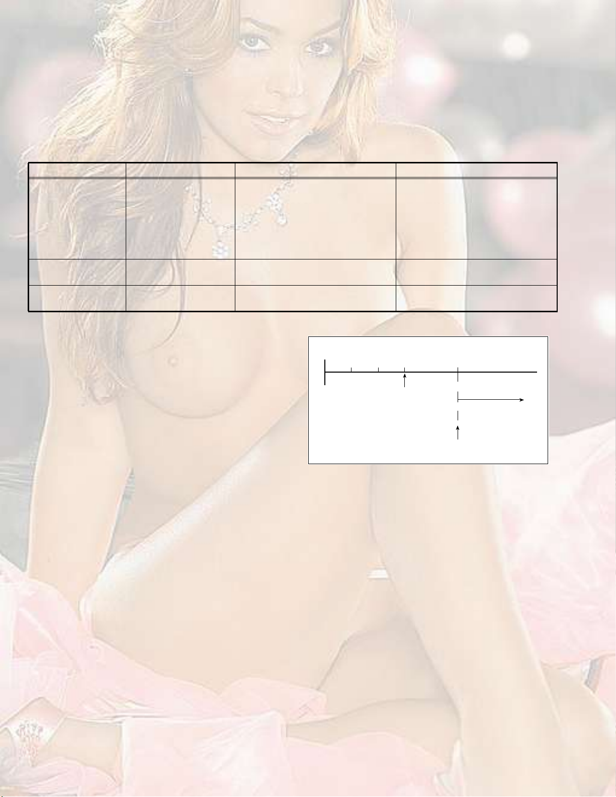
5.1SELF CHECK FUNCTIONS
5.1.1OUTLINE
These models have self-check functions given below. When an abnormality has been detected, the SUB POWER is turned off and
POWER LED is blinking. green An abnormality is detected by the signal input state of the control line connected to the microcomputer.
5.1.2SELF CHECK ITEMS
Check itemDetails of detectionMethod of detectionState of abnormality
B1 over-current
protection
CRT neck broken
protection
X-ray protectionThe rise of a high voltage
5.1.3SELF CHECK INDICATING FUNCTION
When an abnormality has been detected at about 5 seconds
after the power is turned on, the SUB POWER is turned off
immediately and the POWER LED begins blinking green.
An over-current on the low
B line is detected.
Operation of CRT neck
broken protection circuit
valueis detected
The protect port on the microcomputer
(11pin) is always monitored at 150msec
intervals. If an abnormality is detected
nine time successively, it is judged that
there is an abnormality.
DITTODITTO
DITTODITTO
When an abnormality has detected, the
SUB POWER is turned off and POWER
LED begins blinking green. While the
SUB POWER is being turned off, the
POWER key on the remote control unit
is not operational until the power cord is
taken out and put in again.
ߺ¬»® ¿¾±«¬
ë -»½±²¼-
Ü»¬»½¬·±² ±º
¿² ¿¾²±®³¿´·¬§
б©»® ±²
ͬ¿®¬ ±º
¼»¬»½¬·±²
Þ´·²µ·²¹ ÔÛÜ
НЛЮуРСЙЫО СЪЪ
1-30 (No.YA164)
Page 31

Victor Company of Japan, Limited
AV & MULTIMEDIA COMPANY VIDEO DISPLAY CATEGORY 12, 3-chome, Moriya-cho, kanagawa-ku, Yokohama, kanagawa-prefecture, 221-8528, Japan
(No.YA164)
Printed in Japan
VPT
Page 32

ЭСФСЛО МЫФЫКЧНЧСТ
ݱ²¬»²¬-
ШКуозЦШом
ШКуозЦШлм
ШКуозЦШйм
ШКуозКШпм
ШКуозКШлм
ײ¬®±¼«½¬·±² ±º ¬¸» º«²½¬·±²-
Í»¬¬·²¹ «° §±«® ÌÊ
ÌÊ ¾«¬¬±²- ¿²¼ º«²½¬·±²-
λ³±¬» ½±²¬®±´ ¾«¬¬±²-
¿²¼ º«²½¬·±²-
Ë-·²¹ ¬¸» ÌÊù- ³»²«
Þ¿-·½ ±°»®¿¬·±²
РЧЭМЛОЫ НЫММЧТЩ ³»²«
РЧЭМЛОЫ ЪЫЯМЛОЫН ³»²«
НСЛТЬ НЫММЧТЩ ³»²«
ЪЫЯМЛОЫН ³»²«
ЧТНМЯФФ ³»²«
ß¼¼·¬·±²¿´ °®»°¿®¿¬·±²
Ì®±«¾´»-¸±±¬·²¹
Í°»½·º·½¿¬·±²
ò ò ò ò ò ò ò ò ò ò ò ò ò ò ò ò ò ìð
ò ò ò ò ò ò ò ò ò ò ò ò ò í
ò ò ò ò ò ò ò ò ò ò ò ò ïç
ò ò ò ò ò ò ò ò ò ò ò ò ò ò ïç
ò ò ò ò ò ò ò ò ò ò ò îê
ò ò ò ò ò ò ò ò ò ò ò ò ò ò îç
ò ò ò ò ò ò ò ò ò ò íë
ò ò ò ò ò ò ò ò ò ò ò ò ò ò íé
ò ò ò ò ò ò î
ò ò ò ò ò ò ò ò ê
ò ò ò ò ò îð
ò ò ò ò ò ò îë
ò ò ò è
ò ò ò îï
ЩЩМррлкуррпЯуШ
Page 33

Thank you for buying this JVC colour television.
To make sure you understand how to use your new TV, please read this manual thoroughly
before you begin.
WARNING:TO PREVENT FIRE OR SHOCK HAZARD, DO NOT EXPOSE THIS
APPLIANCE TO RAIN OR MOISTURE.
CAUTION:TO ENSURE PERSONAL SAFETY, OBSERVE THE FOLLOWING
RULES REGARDING THE USE OF THIS TV.
1Operate only from the power source indicated on the rear of the TV.
2Avoid damaging the power cord and mains plug. When unplugging the TV, grasp the
mains plug. Do not pull on the power cord.
3Never block or cover the ventilation
openings.
Never install the TV where good ventilation is
unattainable.
When installing this TV, leave spaces for
ventilation around the TV of more than the
minimum distances as shown.
4Do not allow objects or liquid into the cabinet
openings.
5In the event of a fault, unplug the unit and call a service technician. Do not attempt to repair
it yourself or remove the rear cover.
6The surface of the TV screen is easily damaged. Be very careful with it when handling the
TV. Should the TV screen become soiled, wipe it with a soft dry cloth. Never use rub it
forcefully. Never use any cleaner or detergent on it.
7If you are not going to use this TV for a long period of time, be sure to disconnect the AC
plug from the AC socket.
8The apparatus shall not be exposed to dripping or splashing and that no objects filled with
liquids, such as vases, shall be placed on the apparatus.
ïð ½³ ïð ½³ ïë ½³
ïë ½³
ENGLISH
Introduction of the functions
FunctionDescription
DigiPureThe DigiPure function uses the latest digital technology to give you
a natural looking picture.
Progressive Scan
(525P / 625P signal
possible)
Cinema SurroundThe Cinema Surround function gives you a surround sound with a
2
This TV can display the Progressive video signal both of 525P
(NTSC) and 625P (PAL) signal.
live! effect.
Page 34

Setting up your TV
CAUTION
" Turn off all the equipment including the
TV before connecting anything.
1Connecting the aerial and VCR
" Aerial cable is not supplied. Use a
good quality 75-ohm coaxial cable.
" Read the manual that came with the
VCR before connecting.
If not connecting a VCR (see Fig. A):
Connect an aerial cable to the aerial socket
on this TV.
If connecting a VCR (see Fig. B):
1Connect the aerial cable to the aerial
input socket on the VCR, and connect
the VCR and TV with another aerial
cable.
2Connect the VCR s VIDEO OUT (video
output) jack and the TV s VIDEO jack
with a video cable.
Fig. A
Back of the TV
ЯЛЬЧС
Î
ФсУСТС
КЧЬЫС
ÑÊÛÎ
РОсЭОРЮсЭЮЗсКЧЬЫС
ЯЛЬЧС
ФсУСТСÎ
ÎÔ
ЯЛЬЧС
КЧЬЫС
Í
КЧЬЫСуп
КЧЬЫСуо
КЧЬЫСунс
ЭСУРСТЫТМ
СЛМРЛМ
To connect a VCR to the TV with an SVIDEO cable:
Connect the VCR#s S-VIDEO OUT (SVIDEO output) connector and TV#s S
connector with an S-VIDEO cable A,
instead of connecting with a video cable.
3Connect the VCR s AUDIO OUT (audio
L/R output) jacks and the TV s AUDIO
jacks (L/MONO and R) with an audio
cable.
" If the VCR#s audio output is in mono,
connect the VCR#s AUDIO OUT (audio
output) jack and the TV#s AUDIO L/
MONO jack with an audio cable.
Fig. B
ЯЛЬЧС
Î
РОсЭОР
ЯЛЬЧС
ÎÔ
ЯЛЬЧС
Back of the TV
ФсУСТС
КЧЬЫС
ñÝ
ÞÞ
ФсУСТСÎ
КЧЬЫС
Í
ÑÊÛÎ
КЧЬЫСуп
КЧЬЫСуо
ЗсКЧЬЫС
КЧЬЫСунс
ЭСУРСТЫТМ
СЛМРЛМ
3
Page 35

Setting up your TV
2Connecting the power cord
Connect the mains plug to the AC outlet.
3Putting the batteries into the
remote control
Use two AA/R6 batteries.
Insert the batteries from the end, making
surethe and polarities are correct.
" Follow the warnings printed on the
batteries.
" If the remote control does not work
properly, replace the batteries.
" The batteries we supply are only for
setting up and testing your TV. Please
replace them as soon as necessary.
4Making the initial settings
When the TV is first turned on, it enters the
initial setting mode, and the JVC logo is
displayed.
1Press the main power button on the
TV.
The TV is turned on, and the JVC logo
appears.
" If the POWER lamp on the TV lights
red and does not change to green,
your TV is in the standby mode. Press
the POWER button on the remote
control to turn the TV on.
ШКуозЦШом с ШКуозЦШлм с
ШКуозЦШйм
РСЙЫО
×Ò øÊ×ÜÛÑóì÷
ÑÊÛÎ
ÊÎÔñÓÑÒÑ
Í
РСЙЫО
POWER lamp
Main power button
ÓÛÒËÝØßÒÒÛÔÊÑÔËÓÛÌÊñÊ×ÜÛÑ
ÑÕ ÛÈ×Ì
" If the JVC logo does not appear, your
TV has already been turned before. In
this case, use the LANGUAGE! and
AUTO PROGRAM! functions to make
the initial settings. For details, see
INSTALL menu! on page29.
2Press the MENU/OK button.
The LANGUAGE menu appears. You
can choose a language for the on-screen
language.
4
ШКуозКШпм с ШКозКШлм
РСЙЫО
POWER lamp
Main power button
Page 36

3Press the buttons to choose
ENGLISH. Then press the MENU/ OK
button.
The AUTO PROGRAM function starts.
The TV channels you receive are
automatically stored in the PR
(programme numbers) LIST.
" To stop the AUTO PROGRAM
function, press the MENU/OK button.
4After the TV channels have been
stored in the programme numbers
(PR) list, the EDIT menu appears.
Except
HV-29JH24
HV-29VH14
УЛМЧТЩ
НСЛТЬ
ÓÛÒË
ï
ì
é
ОЫМЛОТ
ЪЯКСОЧМЫ ЭШ
ЭЧТЫУЯ
НЛООСЛТЬ
ÑÕ
î
ë
è
õ
ð
НЗНМЫУ
ЭСФСЛО
ЬЧНРФЯЗ
МКсКЧЬЫС
РЧЭМЛОЫ
ÓÑÜÛ
НЛЮуР
ЭШЯТТЫФКСФЛУЫ
Setting up your TV
РСЙЫО
ÆÑÑÓ
Ð×Ð
МКсМЫИМ
í
ê
ç
Except
HV-29JH24
HV-29VH14
Except
HV-29JH54
HV-29VH14
HV-29VH54
" You can proceed to edit the
programme numbers list using the
EDIT/MANUAL function. For details,
see EDIT/MANUAL! on page30.
" If a TV channel you want to view is not
stored in the programme numbers list,
you can register it using the MANUAL
function. For details, see EDIT/
MANUAL! on page30.
" The AUTO PROGRAM function does
not store a TV channel to the
programme number 0 (AV).
" If you do not need to use the EDIT/
MANUAL function, press the MENU/
OK button to close the EDIT menu.
ОУуЭпнлр ÌÊ
HV-29JH74
ЪЯКСОЧМЫ ЭШ
ОУуЭпнлп ÌÊ
HV-29JH24
ЪЯКСОЧМЫ ЭШ
ОУуЭпнлн ÌÊ
HV-29JH54 / HV-29VH54
ЪЯКСОЧМЫ ЭШ
Now, setting up is complete. Please
enjoy your new JVC TV!
HV-29VH14
5
Page 37

TV buttons and functions
ШКуозЦШом с ШКуозЦШлм с
ШКуозЦШйм
РСЙЫО
×Ò øÊ×ÜÛÑóì÷
ÓÛÒËÝØßÒÒÛÔÊÑÔËÓÛÌÊñÊ×ÜÛÑ
ÑÊÛÎ
ÊÎÔñÓÑÒÑÍ
ÑÕ ÛÈ×Ì
РСЙЫО
2
1
ÐÑÉÛÎ
×Ò øÊ×ÜÛÑóì÷
ÓÛÒËÝØßÒÒÛÔÊÑÔËÓÛÌÊñÊ×ÜÛÑ
ÑÊÛÎ
ÊÎÔñÓÑÒÑÍ
ÑÕ ÛÈ×Ì
(Behind the cover)
7
Turn the main power on
Press the main power button .
The POWER lamp 2 lights red and your TV
is in the standby mode.
To turn the main power off:
Press the main power button again. The
POWER lamp 2 goes off.
Turn the TV on from standby
mode
Press the CHANNEL-/+ buttons .
The POWER lamp 2 lights red to green
and your TV will be turned on.
" You can also turn on the TV by
pressing the TV/VIDEO button 3
while it is in standby mode.
Choose a TV channel
Press the CHANNEL-/+ buttons .
ЧТ шКЧЬЫСумч
ÑÊÛÎ
ÊÎФсУСТС
Í
98
ШКуозКШпм с ШКозКШлм
7
УЫТЛЭШЯТТЫФКСФЛУЫМКсКЧЬЫС
ÑÕ ÛÈ×Ì
6543
ÐÑÉÛÎ
2
(Behind the cover)
1
Choose a VIDEO terminal
Press the TV/VIDEO button or
CHANNEL-/+ buttons .
Adjust the volume
Press the VOLUME-/+ buttons .
The volume level indicator appears.
MENU button
Press to open the menu.
For details, see Operation with the buttons
on the TV! on page20.
Remote control sensor
(Behind the cover)
VIDEO-4 terminal
See page35.
Headphone jack
Connect the headphones with a stereo
mini-jack (3.5mm in diameter).
6
ÑÊÛÎ
ÊÎ
ФсУСТС
Í
ЧТ шКЧЬЫСумч
ÓÛÒË
ÝØßÒÛÔ КСФЛУÛÌÊñÊ×ÜÛÑ
ÑÕ
ÛÈ×Ì
Page 38

TV buttons and functions
VIDEO-1 terminal
" See pages 3 and 35.
VIDEO-2 terminal
" See page35.
VIDEO-3/COMPONENT
!
ЯЛЬЧС
ФсУСТС
Î
Î
ЯЛЬЧС
ФсУСТС
Î
Î
ЯЛЬЧС
ЯЛЬЧС
ФсУСТС
Î
РсЭООРсЭ
ЯЛЬЧС
ФсУСТС
Î
Î
ЯЛЬЧС
НКЧЬЫС
ÑÊÛÎ
КЧЬЫСуп
КЧЬЫСуо
ЗсКЧЬЫСЭЮЭ
КЧЬЫСун
ЭСУРСТЫТМ
СЛМРЛМ
Ô
КЧЬЫС
terminal
" See pages 28 and 35.
OUTPUT terminal
" See page35.
Aerial socket
ÑÊÛÎ
ЗсКЧЬЫС
Í
КЧЬЫСуп
КЧЬЫСуо
КЧЬЫСунс
ЭСУРСТЫТМ
СЛМРЛМ
0
-
=
~
Connect the aerial cable.
" See page 3.
КЧЬЫС
ÞÞ
Ô
КЧЬЫС
7
Page 39

Remote control buttons and functions
Turn the TV on from standby
mode
Press the POWER button.
The POWER lamp lights red to green and
your TV will be turned on.
" You can turn on the TV from the
standby mode by pressing the TV/
VIDEO button, the CHANNEL-/+
buttons or the number buttons.
To turn the TV off:
Press the POWER button again.
The POWER lamp changes from green to
red and the TV enters standby mode.
Choose a TV channel
Choose a programme number in which a
TV channel has been set.
Press the CHANNEL-/+ buttons or enter
the programme number (PR) with the
number buttons.
" If you want to put a two-digit channel
into the TV, press the -/--button to
change to the two-digit entry system.
" You can select a channel from the PR
LIST. For details, see DISPLAY
button! on page11.
" If you do not have a clear picture or no
colour appears, follow the operation
procedure COLOUR SYSTEM button!
on page11.
Except
HV-29JH24
HV-29VH14
УЛМЧТЩ
НЗНМЫУ
ЭСФСЛО
ЬЧНРФЯЗ
МКсКЧЬЫС
РЧЭМЛОЫ
ÓÑÜÛ
НЛЮуР
ЭШЯТТЫФКСФЛУЫ
ЭЧТЫУЯ
НЛООСЛТЬ
НСЛТЬ
ÓÛÒË
ÑÕ
ï
ì
é
õ
ОЫМЛОТ
ЪЯКСОЧМЫ ЭШ
ОУуЭпнлр ÌÊ
î
ë
è
ð
HV-29JH74
ЪЯКСОЧМЫ ЭШ
РСЙЫО
ÆÑÑÓ
Ð×Ð
МКсМЫИМ
í
ê
ç
Except
HV-29JH24
HV-29VH14
Except
HV-29JH54
HV-29VH14
HV-29VH54
8
ОУуЭпнлп ÌÊ
HV-29JH24
ЪЯКСОЧМЫ ЭШ
ОУуЭпнлн ÌÊ
HV-29JH54 / HV-29VH54
ЪЯКСОЧМЫ ЭШ
HV-29VH14
Adjust the volume
Press the VOLUME-/+ buttons.
Watch images from an
external device
Choose a VIDEO terminal to which the
external device has been connected.
Press the TV/VIDEO button.
" You can choose a VIDEO terminal with
the CHANNEL-/+ buttons or from the
PR LIST.
To return to a TV channel:
Press the TV/VIDEO button, the
CHANNEL-/+ buttons or the number
buttons.
Page 40

Remote control buttons and functions
MUTING button
Press the MUTING button to turn off the
volume. Pressing the MUTING button again
resumes the previous volume level.
ZOOM button
You can change the screen size according
to the picture aspect ratio. Choose the
optimum one from the following ZOOM
modes.
Press the ZOOM button to choose a
mode.
" The ZOOM button works only in the
normal screen.
REGULAR:
Use to view a normal picture (4:3 aspect
ratio) as its original size is.
ZOOM:
You can zoom up the Wide picture (16:9
aspect ratio) to fill the TV screen.
CINEMA SURROUND button
You can enjoy an enhanced sound for a
wider audience by using CINEMA
SURROUND function.
Press the CINEMA SURROUND button to
select one of CINEMA SURROUND
modes.
HIGH/LOW:
When you listen to the stereo sound, please
select HIGH or LOW mode.
You can enjoy the sound for a wider
audience similar to the experience at the
theatre.
" In case that you setting up the
CINEMA SURROUND function to
HIGH mode, there may be slight
volume distortion. In case that occurs,
please switch the HIGH mode to LOW
mode, the effect of CINEMA
SURROUND functions will be less
noticeable, however, the volume
distortion will be corrected.
MONO:
Select the MONO mode, when you listen to
the mono sound.
You can enjoy the sound for a wider
audience similar to stereo sound.
" The left side and right side of the Wide
picture (16:9 aspect ratio) will be cut
off.
16:9:
This mode converts a normal picture (4:3
aspect ratio) into a Wide picture (16:9
aspect ratio).
" Use for picture with a 16:9 aspect ratio
that have been squeezed into a normal
picture (4:3 aspect ratio), you can
restore their original dimensions.
OFF:
The CINEMA SURROUND function
switches off.
PICTURE MODE button
You can choose one of three PICTURE
MODEs (three kinds of picture setting) to
adjust the picture settings automatically.
Press the PICTURE MODE button to
choose a mode.
BRIGHT:
Heightens contrast and sharpness.
STANDARD:
Standardizes picture adjustment.
SOFT:
Softens contrast and sharpness.
9
Page 41

Remote control buttons and functions
RETURN+ button
The RETURN+ button has two functions;
the RETURN+ function and the RETURN
function. If a channel has been registered
as the Return Channel!, the RETURN+
function operates. If there is no setting for
the Return Channel!, the RETURN function
operates.
RETURN+ function
By registering a channel you frequently
view as the Return Channel!, you can
select that channel at any time simply by
pressing the RETURN+ button.
To register a TV channel as the "Return
Channel#:
Choose the Programme number to which
the channel you want to register has been
set, and press the RETURN+ button and
hold for more than 3 seconds continuously.
RETURN PLUS PROGRAMMED!! is
displayed and the registration is completed.
To cancel a TV channel registered as the
"Return Channel#:
While viewing any TV channel, press the
RETURN+ button and hold for more than 3
seconds continuously. RETURN PLUS
CANCELED!! is displayed and the
registration is cancelled.
" When you turn off the TV, the
registration for the Return Channel! is
cancelled.
" If you want to view the Return
Channel! and another TV channel
alternately, first choose a channel
other than the Return Channel!. And
then press the RETURN+ button to
change the channel to the Return
Channel! In this way, you can view two
channels alternately by pressing the
RETURN+ button.
RETURN function
The TV temporarily memorises the TV
channel that was chosen right before the
current TV channel as the Last Channel!.
By pressing the RETUTN+ button, you can
alternately view the current TV channel and
the Last Channel!.
" If you want to view two channels
alternately by using the RETURN
function, first choose one TV channel
and then choose the other TV channel
with the Number buttons. If you choose
the TV channel without using the
Number buttons, there are cases
where a channel other than the one
you first chose is registered as the
Last Channel!.
/ button
When you are viewing a bilingual broadcast
programme, you can choose the sound
from Bilingual I (Sub I) or Bilingual II (Sub
II).
" When the stereo broadcasting is
received poorly, you can change from
stereo to mono sound so that you can
hear the broadcast more clearly and
easily.
Press the / button to choose a
sound mode.
: Stereo sound
: mono sound
: Bilingual I (sub I)
: Bilingual II (sub II)
MONO: Cancels the Multi Sound function,
and the sound becomes
monaural.
" The sound mode you can choose
differs depending on the TV
programme.
" This function does not work in the
VIDEO modes.
10
Page 42

Remote control buttons and functions
DISPLAY button
You can display the PR LIST, programme
number or VIDEO terminal number on the
screen.
Press the DISPLAY button.
Press the DISPLAY button changes the
display as follows:
No indication
Choose a TV channel or a
VIDEO terminal
1Press the DISPLAY button to display
the PR LIST.
2Press the and buttons to
choose a programme number or
VIDEO terminal.
Then press the MENU/OK button.
" For programme numbers with the
CHANNEL GUARD function set, the n
(CHANNEL GUARD) mark is
displayed next to the programme
number in the PR LIST.
" The VIDEO terminals are registered
after the programme number PR99.
" The AV channel (channel number 0) in
the PR LIST will be chosen only if you
connect the VCR to the TV with an
aerial cable without connecting a video
cable.
COLOUR SYSTEM button
The colour system is chosen automatically.
However, if the picture is not clear or no
colour appears, choose the colour system
manually.
Press the COLOUR SYSTEM button to
choose the appropriate colour system.
AUTO:
This function detects a colour system from
the input signal.
" The AUTO mode may not function
properly if you have poor signal quality.
If the picture is abnormal in the AUTO
mode, choose another colour system
manually.
" The AUTO mode detects a colour
system from the input signal and
chooses the appropriate colour system
automatically.
" For the colour systems in each country
or region, see the table
BROADCASTING SYSTEMS! on
page12.
PAL/SECAM/NTSC3.58/NTSC4.43:
PAL, SECAM, or NTSC colour system.
SOUND SYSTEM button
The sound system is chosen automatically.
However, if you cannot hear the sound
normally even when the picture appears
normally, choose the sound system
manually.
Press the SOUND SYSTEM button to
choose the appropriate sound system.
B/G:B/G system
I:I system
D/K :D/K system
M:M system
" This function does not work in the
VIDEO mode.
" For the sound systems in each country
or region, see the table
BROADCASTING SYSTEMS! on
page12.
11
Page 43

Remote control buttons and functions
BROADCASTING SYSTEMS
For sound and colour systems in your
country or region, refer to the table below:
COLOUR SYSTEM
Area Country or RegionSystem
Bahrain, Kuwait, Oman,
Qatar, United Arab Emirates,
Yemen, etc.
Indonesia, Malaysia,
Singapore, Thailand, India,
Asia,
Middle
East
Europe
OceaniaAustralia, New Zealand, etc.PAL
Africa
etc.
China, Vietnam, etc. PAL
Hong Kong, etc.PAL
Islamic Republic of Iran,
Lebanon, Saudi Arabia, etc.
Philippines, Taiwan,
Myanmar, etc.
Russia, etc.SECAM
Czech Republic, Poland, etc.PAL
Germany, Holland, Belgium,
etc.
UK, etc.PAL
Republic of South Africa, etc.PAL
Nigeria, etc.PAL
Egypt, Morocco, etc.SECAM
PAL
SECAM
NTSC
PAL
Favorite channel
registration
You can register your favorite TV channels
with the colour buttons (Red, Green, Yellow
and Blue). After registration you can recall
the favorite channel by pressing the colour
button.
1In the normal screen, choose a TV
channel (PR01-99) you want to
register.
For detailed operation, see Choose a
TV channel! on page8.
2Press and hold a colour button for 3
seconds or more.
Then FAVORITE CHANNEL
PROGRAMMED!! appears on the screen
and the current channel is registered.
" If the chosen channel is already
registered as the favorite channel,
when a colour button is pressed, the
registered colour button icon appears
on the top right of the screen.
SOUND SYSTEM
Area Country or RegionSystem
Bahrain, Kuwait, Oman,
Qatar, United Arab Emirates,
Yemen, etc.
Indonesia, Malaysia,
Singapore, Thailand, India,
Asia,
Middle
East
Europe
OceaniaAustralia, New Zealand, etc.B/G
Africa
etc.
China, Vietnam, etc. D/K
Hong Kong, etc.I
Islamic Republic of Iran,
Lebanon, Saudi Arabia, etc.
Philippines, Taiwan,
Myanmar, etc.
Russia, etc.D/K
Czech Republic, Poland, etc.D/K
Germany, Holland, Belgium,
etc.
UK, etc.I
Republic of South Africa, etc.I
Nigeria, etc.B/G
Egypt, Morocco, etc.B/G
B/G
B/G
M
B/G
" You cannot register in the Text mode,
or while multiple screens, such as PIP
(picture in picture) are displayed.
" Also you cannot register if the chosen
channel is guarded with the CHANNEL
GUARD function and the screen is
blue, or if an on-screen menu is
displayed.
" Even if you perform AUTO PROGRAM
function, the registration made here
will not be changed. (For AUTO
PROGRAM, see page29.)
Recalling the favorite channel
Press the colour button, then the registered
favorite channel will be displayed.
" You cannot recall the favorite channel
in the Text mode, Menu mode where
an on-screen menu is displayed, or
while multiple screens are displayed.
12
Page 44

Remote control buttons and functions
" The picture effect dedicated for the
colour button applies. For details, see
Setting the picture effect! below:
Setting the picture effect
Each colour button has a dedicated picture
effect. When you choose a favorite channel,
the dedicated picture effect is used. When
shipped, the factory set picture effect is
used for this purpose. However, you can set
this picture effect as required. For details,
see FAVORITE CH SETTING! on page24.
Showing the favorite channels
Press the DISPLAY button to display the
PR LIST.
You can see the favorite channel that has
the registered colour button icon at the right
of the channel number.
Viewing a teletext
programme
[Except HV-29JH54/HV-29VH14/
HV-29VH54]
1Choose a TV channel with a teletext
broadcast.
2Press the TV/TEXT button.
Pressing the TV/TEXT button changes
the mode as follows:
TV mode
TV and
Text mode
ÆÜÚ
ÞÞÝï
Text mode
3Choose a teletext page by pressing
the CHANNEL-/+ buttons, number
buttons or colour buttons.
To return to the TV mode:
Press the TV/TEXT button or TV/VIDEO
button.
" If you have trouble receiving teletext
broadcasts, consult your local dealer
or the broadcast station.
" In the Text mode, the ZOOM mode is
fixed to the REGULAR mode.
" No menu operations are possible
when viewing a teletext programme.
" If characters on a teletext programme
do not appear properly, change the
TELETEXT LANGUAGE setting. For
details, see TELETEXT LANGUAGE!
on page34.
13
Page 45

Remote control buttons and functions
(Hold) button
You can hold a teletext page on the screen
for as long as you want, even while several
other teletext pages are being received.
Press the (Hold) button.
The (hold) are displayed at the top left
of the screen.
To cancel the Hold function:
Press the (Hold) button again.
(Reveal) button
Some teletext pages include hidden text
(such as answers to a quiz).
You can display the hidden text.
Each time you press the (Reveal)
button, text is hidden or revealed.
(Size) button
You can double the height of teletext
display.
Press the (Size) button.
3Press the (Cancel) button to
return to a teletext page when the
page number is on the screen.
" You cannot return to the TV mode with
the (Cancel) button.
(Sub-page) button
Some teletext pages include sub-pages that
are automatically displayed. You can hold
any sub-page, or view it at any time.
1Press the (Sub-page) button to
operate the Sub-page function.
Sub-page numbers are displayed at the
left of the screen.
Colour*Meaning of sub-page number
YellowCurrently being displayed.
WhiteCan be displayed.
Blue or
Red
*: Background colour of the sub-page
number.
Cannot be displayed and it is not
sent.
(Index)button
You can return to the index page instantly.
Press the (Index) button.
" In the List mode, you can return to the
page number displayed in the lower
left area of the screen.
(Cancel) button
You can search for a teletext page while
watching TV.
1Press the number button to enter a
page number, or press the colour
button.
The TV searches for a teletext page.
2Press the (Cancel) button.
The TV programme appears. When the
TV finds the teletext page, its page
number appears in the upper left of the
screen.
2Press the CHANNEL-/+ buttons to
choose a sub-page number.
To cancel the (Sub-page) function:
Press the (Sub-page) button again.
14
Page 46

Remote control buttons and functions
Using the List mode
You can store the numbers of your favorite
teletext pages in memory and call them up
quickly using the colour buttons.
To store the page numbers:
1Press the MODE button to engage the
List mode.
The stored page numbers are displayed
at the bottom of the screen.
2Press a colour button to choose a
position. Then press the number
buttons to enter the page number.
3Press and hold down the (Store)
button.
The four page numbers blink white to
indicate that they are stored in memory.
To call up a stored page:
1Press the MODE button to engage the
List mode.
Twin and PIP (picture in
picture) function
[Except HV-29JH24/HV-29VH14]
You can display two different pictures, the
main picture and sub picture, at a time. In
Twin mode, both pictures are equal in size.
In PIP mode, the small sub picture appears
at a corner of the screen. You can swap the
main picture and sub picture instantly. Note
that the main and sub pictures use different
input sources each other. For example, if
the main picture#s source is TV, the sub
picture#s one will be VIDEO.
While watching a normal picture, press
the PIP button.
Pressing the PIP button changes the mode
as follows:
Normal screen
Twin mode
2Press a colour button to which a page
has been assigned.
To exit the List mode:
Press the MODE button again.
Sub
Main
PIP mode
Sub
Main
" You can also enter this mode while in
the Multi-display mode, Freeze mode
or Strobe mode, except in the Text
mode.
To return to the normal screen:
Press the PIP button until the sub picture
disappears.
" You can hear the sound from the main
picture only.
" In the normal screen, if the current
channel is guarded with the CHANNEL
GUARD function and the screen is
blue, the PIP button does not work.
15
Page 47

Remote control buttons and functions
" When you exit the Twin or PIP mode,
the sub picture lastly displayed will be
saved, and it will appear next time.
" The following table shows what will
happen if the same input sources are
chosen for both main and sub pictures
when you enter the Twin or PIP mode.
If the main picture is the same as the sub
picture, then the sub picture will be
changed to VIDEO-1. But if the main
picture is VIDEO-1, then the sub picture
will be changed to VIDEO-2.
[When the same input sources are chosen]
Main pictureSub picture
TVTV VIDEO-1
VIDEO-1VIDEO-1 VIDEO-2
VIDEO-2VIDEO-2 VIDEO-1
VIDEO-3VIDEO-3 VIDEO-1
VIDEO-4VIDEO-4 VIDEO-1
For the sub picture:
Press the (Input) button.
Each time you press the button, the input
source changes as follow (the one used for
the main picture will be skipped):
VIDEO-1 VIDEO-2 VIDEO-3
VIDEO-4 TV
Swapping the pictures
Press the (Swap) button.
Each time you press the button, the main
picture and the sub picture will be swapped.
Changing the sub picture
position (in PIP mode only)
You can position the sub picture to one of
corners of the main picture.
Press the (Position) button.
Each time you press the button, the sub
picture moves clockwise (lower right
lower left upper left upper right).
" If you press the PIP button when
receiving the Progressive Video Signal
(525P or 625P signal), "525P" or
625P! appears on the screen and the
Twin/PIP function does not operate.
TV channel selection
For the main picture:
Choose a channel using the CHANNEL-/+
buttons or the number buttons.
For the sub picture:
Choose a channel using the SUB-P-/+
buttons.
Input source selection (TV,
VIDEO-1, -2, -3 or -4)
For the main picture:
Press the TV/VIDEO button.
Each time you press the button, the input
source changes as follows (the one used for
the sub picture will be skipped):
VIDEO-1 VIDEO-2 VIDEO-3
VIDEO-4 TV
Setting the colour system of the
sub picture
You can choose the colour system of the
sub picture.
While the sub picture is being displayed,
press the C.SYS button.
Each time you press the button, the colour
system of the sub picture changes as
follows:
AUTO PAL SECAM NTSC3.58
NTSC4.43
" For all source, normally choose AUTO.
" The chosen colour system will not be
saved.
" If the main picture and the sub picture
are of different colour systems, there
will be some differences in the size of
the sub picture and flicker may take
place.
16
Page 48

Remote control buttons and functions
Multi-display function
[Except HV-29JH24/HV-29VH14]
You can watch nine different TV
programmes at a time. As you can display
nine TV programmes successively, this
function is convenient to locate the TV
programme you want. Eight pictures are still
pictures and the last one is the moving
picture with the blue frame. You can choose
any picture as the moving picture and then
watch it in the normal screen.
Entering the Multi-display mode
While watching a TV programme in the
normal screen, press the MULTI button.
The screen changes to the multi-picture
screen and nine pictures are displayed in
the numerical order.
in the Multi-display mode.
" If you press the MULTI button when
receiving the Progressive video signal
(525P or 625P signal), "525P" or
625P! appears on the screen and the
MULTI function does not operate.
Returning to the normal screen
Press the MULTI button or MENU/OK
button, or choose a TV channel with the
number buttons.
The moving picture with the blue frame will
be displayed in the normal screen.
" Pressing the TV/VIDEO button will also
returns the TV to the normal screen.
Choosing a picture as the
moving one
You can choose one of the pictures as the
moving picture with the blue frame.
Moving picture with the blue frame
"
You can also enter this mode while in the
Twin mode, but not in the Text mode.
" Pictures will appear in the assigned
order in the PR LIST (PR01-99).
" If the number of pictures to be
displayed at a time is less than nine,
fewer pictures than nine will be
displayed.
" The guarded channel with the
CHANNEL GUARD function will be
skipped and will not be displayed.
" You cannot display a video image in
the Multi-display mode.
" The RETURN+ button, svt/u button,
COLOUR SYSTEM button and
SOUND SYSTEM button are disabled
Press and buttons to move the
blue frame.
The chosen picture becomes the moving
picture.
" Pressing the 3 button in the right-most
position 3! or 6! will scroll the blue
frame to the next position, 4! or 7!.
While, pressing the 2 button in the leftmost position 4! or 7! will scroll the
blue frame to the previous position, 3!
or 6!.
Displaying the next nine pictures
Press the NEXT button.
The next nine pictures will be displayed at a
time. By pressing the NEXT button
successively, you can display all available
pictures except video images.
Displaying the channel numbers
on the multi-display screen
Press the DISPLAY button.
Respective channel numbers appear on the
nine pictures.
To go off the channel numbers:
Press the DISPLAY button again.
17
Page 49

Remote control buttons and functions
Freeze function
[Except HV-29JH24/HV-29VH14]
While watching a picture, you can capture a
still picture you want. The captured still
picture and the moving picture are
displayed at a time. (They are the pictures
of the same source.)
Press the (Freeze) button.
Still picture is captured and displayed on the
right side of the screen. On the left, the
moving picture is displayed.
Moving
picture
" The (Freeze) button does not work
in the Text mode.
Still
picture
Strobe function
[Except HV-29JH24/HV-29VH14]
You can display eight consecutive still
pictures and one moving picture at a time.
(They are the pictures of the same source.)
Press the STROBE button.
Eight consecutive still pictures which are
captured at intervals of about 0.2 second
are displayed in the order of 1! to 9!.
(These numbers are not actually displayed.)
To return to the normal screen:
Press the (Freeze) button again or
press the number buttons to choose a
channel.
" You cannot use the FREEZE button
when the sub picture or the main
picture are displayed on the screen.
" If the current channel is guarded with
the CHANNEL GUARD function and
the screen is blue, this button does not
work.
" If you press the FREEZE button when
receiving the Progressive video signal
(525P or 625P signal), "525P" or
625P! appears on the screen and the
FREEZE function does not operate.
" The STROBE button does not work in
the Text mode.
To return to the normal screen:
Press the STROBE button again or press
the number buttons to choose a channel.
" If signal level of the main picture is
weak, the still images become
abnormal.
" You cannot use the STROBE button
when the sub picture or the main
picture are displayed on.
" If the current channel is guarded with
the CHANNEL GUARD function and
the screen is blue, the STROBE button
does not work.
" If you press the STROBE button when
receiving the Progressive video signal
(525P or 625P signal), "525P" or
625P! appears on the screen and the
STROBE function does not operate.
18
Page 50

Using the TV s menu
This TV has a number of functions you can operate using menus.
To fully utilize all your TV#s functions, you need to understand the basic menu operating
techniques fully.
" The following remote control is for HV-29JH74. However, the buttons used for setting TV
menus are common to all models.
Basic operation
1Press the MENU/OK button to display
the MENU (main menu).
УЛМЧТЩ
НСЛТЬ
ï
ì
é
ЭЧТЫУЯ
НЛООСЛТЬ
ÓÛÒË
ÑÕ
õ
î
ë
è
НЗНМЫУ
ЭСФСЛО
ЬЧНРФЯЗ
МКсКЧЬЫС
РЧЭМЛОЫ
ÓÑÜÛ
НЛЮуР
ОЫМЛОТ
ð
ЭШЯТТЫФКСФЛУЫ
ЪЯКСОЧМЫ ЭШ
РСЙЫО
ÆÑÑÓ
Ð×Ð
МКсМЫИМ
í
ê
ç
" The display appearing at the bottom of
a menu indicates buttons on the
remote control you can use when you
operate a chosen function.
ÑÕ
ÌÊ
ЬЧНРт
MENU/OK button
TV/VIDEO button
DISPLAY button
2Press the buttons or to
choose a menu title, and press the
MENU/OK button.
The menu appears.
To return to the previous menu:
Press the DISPLAY button.
ОУуЭпнлр ÌÊ
To exit a menu instantly:
Press the TV/VIDEO button.
3Press the buttons to choose a
function.
" For details of the functions in the
menus, see the following pages.
19
Page 51

Using the TV#s menu
4Press the buttons to choose the
setting of that function.
" If you want to operate a function which
appears only with its name, follow the
descriptions of that function on the
following pages.
" The display appearing at the bottom of
a menu shows you a button on the
remote control that you can use when
you operate a chosen function.
5Press the MENU/OK button to
complete the setting.
The menu disappears.
" When watching the television with the
NTSC system, the menus as displayed
at about half of their normal vertical
size.
Operation with the buttons on the
TV
You can also operate the menus using the
buttons on the front panel of the TV.
HV-29JH24/HV-29JH54/HV-29JH74
УЫТЛЭШЯТТЫФ
КСФЛУЫ
МКсКЧЬЫС
PICTURE SETTING menu
PICTURE MODE
You can choose one of three PICTURE
MODEs to adjust the picture settings
automatically.
BRIGHT:
Heightens contrast and sharpness.
STANDARD:
Standardizes picture adjustment.
SOFT:
Softens contrast and sharpness.
" You can also operate the PICTURE
MODE function with the PICTURE
MODE button on the remote control.
For details, see PICTURE MODE
button! on page9.
ÑÕ ÛÈ×Ì
OK
buttons buttons buttons
HV-29VH14/HV-29VH54
OK
buttons buttons buttons
УЫТЛСХЭШЯТТЫФ
КСФЛУЫ
TV/VIDEO
buttons
TV/VIDEO
buttons
МКсКЧЬЫС
ЫИЧМ
" There is no DISPLAY button on the
front panel of the TV, which will be
used for menu operation.
Adjusting the picture
You can change the picture settings of each
picture mode, as you like. The picture
settings changed are stored in the picture
mode.
CONTRAST
You can adjust the picture contrast.
2 : lower
3 : higher
BRIGHT
You can adjust the picture brightness.
2 : darker
3 : brighter
SHARP
You can adjust the picture sharpness.
2 : softer
3 : sharper
20
Page 52

Using the TV#s menu
COLOUR
You can adjust the picture colour.
2 : lighter
3 : deeper
TINT
You can adjust the picture tint.
2 : reddish
3 : greenish
" You can change the TINT setting
(picture tint) only when the colour
system is NTSC 3.58 or NTSC 4.43.
" You cannot select the TINT function
when receiving the Progressive video
signal (525P and 625P signals).
To return to the default settings in each
PICTURE MODE:
Press the blue button. This will return the
picture settings in the currently chosen
PICTURE MODE to the default settings,
and stores them in the PICTURE MODE
again.
WHITE BALANCE
You can select one of three WHITE
BALANCE modes (three tones of white) to
adjust the white balance of the picture.
Since white is the colour which is used as a
reference for all the other colours, changing
the WHITE BALANCE mode affects the
appearance of all the other colours on the
screen.
COOL:
A bluish white. Using this mode when
watching bright pictures allows you to enjoy
a more vivid and bright picture.
MID:
The normal white colour.
WARM:
A radish white. Using this mode when
watching films allows you to enjoy colours
that are characteristic of films.
" You cannot select the WHITE
BALANCE function in the 16:9 mode
of the ZOOM function.
PICTURE FEATURES menu
DIGITAL VNR
The DIGITAL VNR function cuts down the
amount of noise in the original picture.
AUTO:
The TV will be automatically adjust the level
of the DIGITAL VNR effect to match the
amount of noise in the picture, giving you
the best possible picture.
" If you set the DIGITAL VNR effect too
high it can make the picture less sharp.
It is recommended to use the AUTO
setting if you can.
MAX:
The level of the DIGITAL VNR effect is set
to the maximum. If you set the DIGITAL VNR
function to AUTO but still notice some noise,
change the setting from AUTO to MAX.
" The MAX setting is not suitable for
high-quality pictures which contain a
lot of noise.
OFF:
The level of the DIGITAL VNR effect is set
to OFF.
MIN:
The level of the DIGITAL VNR effect is set to
the minimum. If you set the DIGITAL VNR
function to AUTO but feel that the sharpness
of the original picture has not been reproduced
fully, change the setting from AUTO to MIN.
" The MIN setting is not suitable for low-
quality pictures which contain a lot of noise.
21
Page 53

Using the TV#s menu
DigiPure
The Digipure function uses the latest in
digital technology to give you a natural
looking picture. The Digipure function
includes the following two functions.
Digipure function:
This function helps to create a natural
looking picture by eliminating unnecessary
edges from high-contrast and crisp images.
Conversely, for images with low-contrast,
edges are added to produce a sharper,
more detailed picture.
You can choose from the DigiPure function
settings of AUTO, MIN and MAX.
Picture motion compensation function:
This function displays fast-moving pictures
(for example, the players or ball in a football
game) more smoothly and naturally on the
screen.
AUTO:
The TV will automatically adjust the level of
the DigiPure effect to match the amount of
noise in the picture, giving the best possible
picture.
" If you set the DigiPure effect too high
on a low-quality picture that contains a
lot of noise, this may actually make the
noise worse. It is recommended to use
the AUTO setting if you can.
MAX:
The level of the DigiPure effect is set to the
maximum. If you set the DigiPure function
to AUTO but feel that the original picture
quality has not been reproduced fully,
change the setting from AUTO to MAX.
MIN:
The level of the DigiPure effect is set to the
minimum. When you set the DigiPure
function to AUTO and notice some noise,
change the setting from AUTO to MIN.
" The MIN setting is not suitable for
high-quality pictures which contain
very little noise.
PULL DOWN
The PULL DOWN function displays a
cinema film picture more smoothly and
naturally on the screen.
AUTO:
This function is turned on. Normally keep
this function set to AUTO.
ON :
This function is turned on.
OFF:
This function is turned off.
" The motion may appear unnatural
when viewing images with the NTSC
colour system. To make the motion
smoother, switch the PULL DOWN
function from AUTO or ON to OFF.
" You cannot select this function in the
Twin pictures mode.
" You cannot select this function when
receiving the Progressive video signal
(525P and 625P signals).
When TV displays Twin, PIP, Multi-display,
FREEZE, or STROBE function, PULL
DOWN function cannot operate.
" The MAX setting is not suitable for
low-quality pictures which contain a lot
of noise.
OFF:
The DigiPure function is turned off.
22
Page 54

Using the TV#s menu
COLOUR SYSTEM
The colour system is chosen automatically.
However, if the picture is not clear or no
colour appears, choose the colour system
manually.
1Choose COLOUR SYSTEM, then
press the buttons to choose the
appropriate colour system.
" You can also operate the COLOUR
SYSTEM function with the COLOUR
SYSTEM button on the remote control.
For details, see COLOUR SYSTEM
button! on page11.
ZOOM
You can change the screen size according
to the picture aspect ratio. Choose the
optimum one from three ZOOM modes.
1Choose ZOOM, then press the MENU/
OK button.
2Press the buttons to choose a
ZOOM mode. Then press the MENU/
OK button.
" You can choose a ZOOM mode from
REGULAR, ZOOM or 16:9 modes. For
details, see ZOOM button! on page9.
PICTURE TILT
There are cases where the Earth#s
magnetic force may make the picture tilt. If
this happens, you can correct the picture tilt.
1Choose PICTURE TILT, then press the
MENU/OK button.
2Press the buttons until the
picture becomes level. Then press the
MENU/OK button.
23
Page 55

Using the TV#s menu
FAVORITE CH SETTING
You can set a dedicated picture effect for
the favorite channels registered to the
colour buttons (Red, Green, Yellow and
Blue). For favorite channel registration, see
Favorite channel registration! on page12.
1Choose FAVORITE CH SETTING, then
press the MENU/OK button.
2Press the button to choose
FAVORITE CHANNEL, then press the
button to choose the registered
favorite channel.
Each time you press the button, the
colour button icon (Red, Green, Yellow
or Blue) of the registered favorite
channel and its channel number (e.g.
PR1) appear.
3Set the picture effect.
Press the 6 button to choose an item
listed in the following table and press the
5 button to choose one of options.
" As explained in the table, if PICTURE
EFFECT is set to OFF, the dedicated
picture effect for the favorite channel is
not used. In this case, normal picture
effect is used.
" For details of each item, see
PICTURE MODE! on page20,
DIGITAL VNR! on page21, WHITE
BALANCE! on page21, DigiPure! on
page22.
ItemOptions
PICTURE MODEBRIGHT*, STANDARD,
SOFT
DIGITAL VNRAUTO*, MAX, OFF, MIN
WHITE
BALANCE
DigiPureAUTO*, MAX, OFF, MIN
PICTURE
EFFECT
*: When shipped
4Press the MENU/OK button to
complete the setting.
COOL, MID*, WARM
ON*:
Above picture effect
applies to the chosen
favorite channel.
OFF:
No picture effect applies.
VIDEO SETTING
You can set a dedicated picture effect for
the video inputs, VIDEO-1 to -4.
1Choose VIDEO SETTING, then press
the MENU/OK button.
24
2Press the button to choose
VIDEO STATUS, then press the
button to choose one of video inputs,
VIDEO-1 to -4.
Page 56

Using the TV#s menu
3Set the picture effect.
Press the 6 button to choose an item
listed in the following table and press the
5 button to choose one of options.
" As explained in the table, the
PICTURE EFFECT for the video inputs
is set to OFF when shipped. To use it,
you need to set it ON.
ItemOptions
PICTURE MODEBRIGHT*, STANDARD,
SOFT
DIGITAL VNRAUTO*, MAX, OFF, MIN
WHITE
BALANCE
DigiPureAUTO*, MAX, OFF, MIN
PICTURE
EFFECT
*: When shipped
" For details of each item, see
PICTURE MODE! on page20,
DIGITAL VNR! on page21, WHITE
BALANCE! on page21, DigiPure! on
page22.
" Pressing the number button 0! will
return the picture effect to the factory
set value.
4Press the MENU/OK button to
complete the setting.
COOL, MID*, WARM
ON:
Above picture effect
applies to the chosen
video input.
OFF*:
No picture effect applies.
SOUND SETTING menu
STEREO / I$II
When you are viewing a bilingual broadcast
programme, you can choose the sound
from Bilingual I (sub I) or Bilingual II (sub II).
When the stereo broadcasting is received
poorly, you can change from stereo to mono
sound so that you can hear the broadcast
more clearly and easily.
:Stereo sound
: mono sound
: Bilingual I (sub I)
: Bilingual II (sub II)
MONO:Cancels the Multi Sound function,
and the sound becomes monaural.
" The sound mode you can choose
differs depending on the TV
programme.
" This function does not work in the
VIDEO modes.
" You can also operate the STEREO /
I"II function with the svt/u button.
For details, see svt/u button! on
page10.
Adjusting the sound
You can adjust the sound to your liking.
BASS
You can adjust the low tone of the sound.
2 : weaker
3 : stronger
TREBLE
You can adjust the high tone of the sound.
2 : weaker
3 : stronger
25
Page 57

Using the TV#s menu
BALANCE
You can adjust the volume balance
between the left and right speakers.
2 : turn the left speaker#s volume level up.
3 : turn the right speaker#s volume level up.
AI VOLUME
You can prevent the sudden increase or
decrease of sound that occurs when
changing the channel to another channel or
switching the VIDEO mode to another
VIDEO mode.
ON:
This function is turned on.
OFF:
This function is turned off.
" The AI VOLUME function may not
operate as expected if the sound input
level from a broadcast station (or video
software) is extremely low.
FEATURES menu
SLEEP TIMER
You can set the TV to automatically turn off
after a set time.
1Choose SLEEP TIMER, then press the
MENU/OK button.
CINEMA SURROUND
You can enjoy Surround sound with a live!
effect by using the CINEMA SURROUND
function.
" You can choose a CINEMA
SURROUND mode from HIGH, LOW,
MONO and OFF modes. For details,
see CINEMA SURROUND button! on
page9.
" You can also operate the CINEMA
SURROUND function with the
CINEMA SURROUND button. For
details, see CINEMA SURROUND
button! on page9.
2Press the buttons to set the
period of time.
The TV begins count down from the set
time.
" You can set the period of time a
maximum of 120 minutes (2 hours) in
10 minute steps.
To cancel this function:
" Press the 2 button to set a period of
time to OFF!.
3Press the MENU/OK button to
complete the setting.
The menu disappears.
" One minute before this function turns
off the TV, GOOD NIGHT!! appears.
" This function cannot be used to turn off
the TV#s main power.
" When this function is on, you can
display the SLEEP TIMER menu again
to confirm or change the remaining
time.
26
Page 58

Using the TV#s menu
BLUE BACK
You can set the TV to automatically change
to a blue screen and mute the sound if the
signal is weak or absent, or when there is
no input from an external device.
ON:
This function is turned on.
OFF:
This function is turned off.
CHILD LOCK
You can disable the front control buttons of
the TV. When this function is set to ON, the
TV can be operated only by using the
remote control.
Use this function to prevent children from
operating the TV at their own discretion
(without parent consent).
ON:
This function is turned on.
2Set the ID number you want.
To choose a number:
Press the 6 buttons.
To move a cursor:
Press the 5 buttons.
3Press the MENU/OK button.
4Press the buttons to choose a TV
channel.
" The TV shows the TV programme
which the chosen TV channel is now
broadcasting.
OFF:
This function is turned off.
CHANNEL GUARD
When there is a TV channel you do not
want your children to watch, you can lock
out the channel. Even when a child chooses
a programme number for a locked out
channel the screen will change to blue and
display n so the channel cannot be viewed.
To set this function:
1Choose CHANNEL GUARD, then
press the number 0 (AV) button.
5Press the blue button to set this
function to the TV channel.
n (CHANNEL GUARD) appears and the
TV channel is locked.
To cancel this function:
Press the blue button again.
n (CHANNEL GUARD) disappears and
the lock is released.
6Press the MENU/OK button to
complete the setting.
The menu disappears.
To view a locked TV channel:
1Choose a programme number in
which a TV channel locked with the
number buttons or PR LIST.
The screen changes to blue and the n
(CHANNEL GUARD) appears.
" You cannot choose a locked TV
channel with the 6 buttons.
27
Page 59

Using the TV#s menu
2Press the DISPLAY button to display
"ID NO.# (ID number input screen).
3Press the number buttons to enter the
ID number.
The lock is temporarily released so you
can view the TV channel.
If you have forgotten the ID number:
Perform step 1 of To set this function:! on
page27. After confirming the ID number,
press the TV/VIDEO button to exit the menu.
" When you would like to cancel the
CHANNEL GUARD function, you must
perform the operation To set this
function! again.
AUTO SHUTOFF
You can set your TV to turn off if no signal is
received for about 15 minutes or longer
after the end of a broadcast.
ON:
This function is turned on.
OFF:
This function is turned off.
" The AUTO SHUTOFF function does
not turn off the TV#s main power.
" The AUTO SHUTOFF will not work for
a VIDEO mode.
Additional preparation! on page35.
This Television is compatible with the
Progressive video signal (525P signal
and 625P signal) only when the
component video signal is input.
PIP
[Except HV-29JH24/HV-29VH14]
You can enter the Twin or PIP mode from
the menu without using the remote control.
This menu will be useful if you cannot find
the remote control around you.
" For detailed description of Twin and
PIP mode, see Twin and PIP (picture
in picture) function! on page15.
1Choose PIP, then press the MENU/OK
button.
2Display Twin or PIP picture as you like.
First press the 6 button to choose an
item listed, then press the 5 button to
choose one of options, then press the
MENU/OK button.
PIP/TWIN
Each time you press the 5 button, the
screen mode changes as follows:
ÌÉ×Ò Ð×Ð ÑÚÚ ø²±®³¿´ -½®»»²÷
VIDEO-3 SETTING
Set the VIDEO-3 SETTING correctly
according to the video signal input from the
external device connected to the VIDEO-3
terminal. If this setting is incorrect, images
will not be displayed.
VIDEO:
If a normal video signal (composite video
signal) is input.
COMPONENT:
If a Component video signal (Y/CB/CR
signals) is input.
" For detailed connecting methods, see
28
SUB INPUT
Each time you press the 5 button, the
input source of the sub picture changes as
follows:
КЧЬЫСуп КЧЬЫСуо КЧЬЫСун
МК КЧЬЫСум
SWAP
Each time you press the MENU/OKbutton,
the main picture and the sub picture will be
swapped.
" If PIP/TWIN is selected OFF, then
SUB INPUT and SWAP disappears in
PIP menu.
Page 60

INSTALL menu
Using the TV#s menu
" To stop the AUTO PROGRAM
function, press the MENU/OK button.
LANGUAGE
You can choose the language you want to
use for the on-screen display from the
language list in a menu.
1Choose LANGUAGE, then press the
MENU/OK button.
2Press the buttons to choose a
language.
3Press the MENU/OK button to
complete the setting.
The menu disappears.
AUTO PROGRAM
You can automatically register the TV
channels which can be received well at your
residence in the TV#s programme numbers
by performing the following.
1Choose AUTO PROGRAM, then press
the MENU/OK button.
The AUTO PROGRAM function starts.
The TV channels you receive are
automatically stored in the programme
numbers list.
2After the TV channels have been
stored in the programme number list,
the EDIT menu appears.
" You can proceed to edit the
programme numbers list using the
EDIT/MANUAL function. For details,
see EDIT/MANUAL! on page30.
" If a TV channel you want to view is not
stored in the programme numbers list,
you can register it using the MANUAL
function.
For details, see EDIT/MANUAL! on
page30.
" The AUTO PROGRAM function does
not store a TV channel to the
programme number 0 (AV).
" If you do not need to use the EDIT/
MANUAL function, press the MENU/
OK button to exit the EDIT menu.
29
Page 61

Using the TV#s menu
EDIT/MANUAL
The EDIT/MANUAL functions are divided
into two types: editing of the current
programme numbers (EDIT functions) and
manual registration of a TV channel you
want to view to the programme number
(MANUAL function).
CAUTION
" Using the MOVE, DELETE or INSERT
function rewrites the current programme
numbers list.
Resultingly, the programme number of
some of the TV channels will change.
" When a TV channel which has been
locked out using the CHANNEL GUARD
function, using the MANUAL function for
that TV channel cancels the CHANNEL
GUARD function.
" When a TV channel has already been
registered in PR 99, using the INSERT
function deletes the TV channel.
INSERT:
This function adds a new TV channel in
the current programme numbers list by
using the CH/CC number.
DELETE:
This function deletes an unnecessary TV
Channel.
MANUAL:
This function manually registers a new
TV channel in a programme number.
3Press the MENU/OK button to
complete the setting.
" For programme number PR 0, AV!
appears in the programme numbers
list.
FUNCTIONS
MOVE
1Press the buttons to choose a TV
channel.
1Choose EDIT/MANUAL, then press the
MENU/OK button.
2Follow the operation description of a
function you want to use and operate
the function.
MOVE:
This function changes a programme
number of a TV channel.
2Press the button to start the MOVE
function.
3Press the buttons to choose a
new programme number.
To cancel the MOVE function:
Press the DISPLAY button.
4Press the button to change the
programme number of a TV channel
to a new programme number.
30
ID:
This function registers a Channel name
(ID) to a TV channel.
Page 62

ID
1Press the buttons to choose a TV
channel.
2Press the red button to start the ID
function.
3Enter a channel name (ID). Press the
buttons to choose a character.
Press the buttons to move the
cursor.
To cancel the ID function:
Press the DISPLAY button.
4Press the MENU/OK button to register
a channel name to a TV channel.
DELETE
1Press the buttons to choose a TV
channel.
2Press the yellow button to delete the
TV channel.
The TV channel is deleted from the
programme numbers list.
Using the TV#s menu
To cancel the MANUAL function:
Press the DISPLAY button.
3Press the button to choose the
system (sound system) for a TV
channel you want to register.
" For the sound systems in each country
or region, see the table
BROADCASTING SYSTEMS! on
page12.
4Press the green or red button to
search for a TV channel.
Scanning stops when the TV finds a TV
channel. Then the TV channel is
displayed.
5Press the green or red button
repeatedly until the TV channel you
want appears.
If the TV channel reception is poor:
Press the blue or yellow button to finetune the TV channel.
MANUAL
1Press the buttons to choose a
programme number to which you
want to register a new TV channel.
2Press the blue button to activate the
MANUAL function.
At the right side following the CH/CC
number, the SYSTEM (sound system) of
the TV channel appears.
If you cannot hear the normal sound
even when the picture of the TV
channel appears normally:
The SYSTEM setting is wrong. Press the
3 button and choose a SYSTEM that has
normal sound.
6Press the MENU/OK button and
register the TV channel to a
programme number.
The normal EDIT menu is resumed.
31
Page 63

Using the TV#s menu
INSERT
Preparation:
" Find the CH/CC number
corresponding to the channel number
of the TV channel from page33.
1Press the buttons to choose a
programme number for which you will
register a new TV channel.
" When you attempt to insert the TV
channel of NTSC-M system, press
SOUND SYSTEM button to switch
SOUND SYSTEM to M, then proceed
to the next step.
2Press the green button to start the
INSERT function.
3Press the buttons to choose "CC#
or "CH# according to the CH/CC
number of the TV channel.
To cancel the INSERT function:
Press the DISPLAY button.
4Press the Number buttons to enter the
remaining CH/CC number.
The TV shifts to registration mode. When
the registration is completed, the picture
of the TV channel appears on the
screen.
" The CH/CC number is a number
indicating the broadcast frequency to
the TV. If the TV cannot detect the TV
channel corresponding to the
broadcast frequency indicated by the
CH/CC number, a picture in the nosignal state appears.
32
Page 64

Using the TV#s menu
CH/CC number
When you want to use the INSERT function on page32, find the CH/CC number
corresponding to the Channel number of the TV channel from this table.
US: The US channel numbers are the channel numbers used in the United States,
Philippines, etc. CCIR: The CCIR channel numbers are the channel numbers used in the
Middle East, Southeast Asia, etc. OIRT: The OIRT channel numbers are the channel
numbers used in Eastern Europe, Russia, Vietnam, etc. AUSTRALIA: The AUSTRALIA
channel numbers are the channel numbers used in Australia, etc.
ChannelChannel
ЭШЛНЭЭЧОСЧОМЯЛНМОЯФЧЯ
ЭШ роЛНуоЫоОпЯЛур
ЭШ рнЛНунЫнЯЛуп
ЭШ рмЛНумЫмОоЯЛуо
ЭШ рлЛНулЫлОкЯЛук
ЭШ ркЛНукЫкОйЯЛуй
ЭШ рйЛНуйЫйОиЯЛуи
ЭШ риЛНуиЫиОзЯЛуз
ЭШ рзЛНузЫз
ЭШ прЛНупрЫпрОпрЯЛупр
ЭШ ппЛНуппЫппОппЯЛупп
ЭШ поЛНупоЫпоОпо
ЭШ пнЛНупн
ЭШ пмЛНупм
ЭШ плЛНупл
ЭШ пкЛНупк
ЭШ пйЛНупй
ЭШ пиЛНупи
ЭШ пзЛНупз
ЭШ орЛНуор
ЭШ опЛНуопЫоп
ЭШ ооЛНуооЫоо
ЭШ онЛНуонЫон
ЭШ омЛНуомЫом
ЭШ олЛНуолЫол
ЭШ окЛНуокЫок
ЭШ ойЛНуойЫой
ЭШ оиЛНуоиЫои
ЭШ озЛНуозЫоз
ЭШ нрЛНунрЫнр
ЭШ нпЛНунпЫнп
ЭШ ноЛНуноЫно
ЭШ ннЛНуннЫнн
ЭШ нмЛНунмЫнм
ЭШ нлЛНунлЫнл
ЭШ нкЛНункЫнк
ЭШ нйЛНунйЫнй
ЭШ ниЛНуниЫни
ЭШ нзЛНунзЫнз
ЭШ мрЛНумрЫмр
ЭШ мпЛНумпЫмп
ЭШ моЛНумоЫмо
ЭШ мнЛНумнЫмн
ЭШ ммЛНуммЫмм
ЭШ млЛНумлЫмл
ЭШ мкЛНумкЫмк
ЭШ мйЛНумйЫмй
ЭШ миЛНумиЫми
ЭШ мзЛНумзЫмз
ЭШ лрЛНулрЫлр
ЭШ лпЛНулпЫлп
ЭШ лоЛНулоЫло
ЭШ лнЛНулнЫлн
ЭШ лмЛНулмЫлм
ЭШ ллЛНуллЫлл
ЭШ лкЛНулкЫлк
ЭШ лйЛНулйЫлй
ЭШ лиЛНулиЫли
ЭШ лзЛНулзЫлз
ЭШ крЛНукрЫкр
ЭШ кпЛНукпЫкп
ЭШ коЛНукоЫко
ЭШ кнЛНукнЫкн
ЭШ кмЛНукмЫкм
ЭШ клЛНуклЫкл
ЭШ ккЛНуккЫкк
ЭШ кйЛНукйЫкй
ЭШ киЛНукиЫки
ЭШ кзЛНукзЫкз
ЭШ йр
ЭЭЛНЭЭЧОСЧОМЯЛНМОЯФЧЯ
ЭЭ рпНупЯЛул
ЭЭ роНуо
ЭЭ рнНун
ЭЭ рмНум
ЭЭ рлНул
ЭЭ ркНукЯЛулЯ
ЭЭ рйНуй
ЭЭ риНуи
ЭЭ рзНуз
ЭЭ прНупр
ЭЭ ппНупп
ЭЭ поНупо
ЭЭ пнНупн
ЭЭ пмЯНупм
ЭЭ плЮНупл
ЭЭ пкЭНупк
ЭЭ пйЬНупй
ЭЭ пиЫНупи
ЭЭ пзЪНупз
ЭЭ орЩНуор
ЭЭ опШНуоп
ЭЭ ооЧНуоо
ЭЭ онЦНуон
ЭЭ омХНуом
ЭЭ олФНуол
ЭЭ окУНуок
ЭЭ ойТНуой
ЭЭ оиСНуои
ЭЭ озРНуоз
ЭЭ нрПНунр
ЭЭ нпОНунп
ЭЭ ноННуно
ЭЭ ннМНунн
ЭЭ нмЛНунм
ЭЭ нлКНунл
ЭЭ нкЙНунк
ЭЭ нйЙхпНунй
ЭЭ ниЙхоНуни
ЭЭ нзЙхнНунз
ЭЭ мрЙхмНумр
ЭЭ мпЙхлНумп
ЭЭ моЙхк
ЭЭ мнЙхй
ЭЭ ммЙхи
ЭЭ млЙхз
ЭЭ мкЙхпр
ЭЭ мйЙхпп
ЭЭ миЙхпо
ЭЭ мзЙхпн
ЭЭ лрЙхпм
ЭЭ лпЙхпл
ЭЭ лоЙхпк
ЭЭ лнЙхпй
ЭЭ лмЙхпи
ЭЭ ллЙхпз
ЭЭ лкЙхор
ЭЭ лйЙхоп
ЭЭ лиЙхоо
ЭЭ лзЙхон
ЭЭ крЙхом
ЭЭ кпЙхол
ЭЭ коЙхок
ЭЭ кнЙхой
ЭЭ кмЙхои
ЭЭ йлИ
ЭЭ йкЗОн
ЭЭ ййЖОмЯЛун
ЭЭ йиЖхпОл
ЭЭ йзЖхоЯЛум
ЭЭ злЯул
ЭЭ зкЯум
ЭЭ зйЯун
ЭЭ зиЯуо
ЭЭ ззЯуп
33
Page 65

Using the TV#s menu
TELETEXT LANGUAGE
[Except HV-29JH54/HV-29VH14/
HV-29VH54]
There are five types of teletext language
groups. Set the teletext language group that
corresponds to the language of the teletext
program that you want to watch.
1Choose TELETEXT LANGUAGE, then
press the MENU/OK button.
2Press the buttons to choose a
group.
3Press the MENU/OK button to
complete the setting.
The menu disappears.
" Languages that are not included in the
teletext language group that you
select, the sub-titles of the teletext
program will not be displayed properly.
Group Languages
Turkish, Hungarian, English,
GROUP-1
GROUP-2
GROUP-3
GROUP-4
GROUP-5
German, French, Italian,
Spanish, Portuguese, Greek,
Swedish, Finnish
Polish, Serbian, Croatian,
Slovenian, Czech, Slovak,
Rumanian, Hungarian, German, French, Italian, Swedish,
Finnish
Russian, Bulgarian, Lettish,
Lithuanian, Estonian, Ukrainan, Czech, Slovak, English,
German, Rumanian
Arabic, Czech, Slovak. Hungarian, English, German,
French, Italian, Spanish, Portuguese, Swedish, Finnish
Farsi, Czech, Slovak. Hungarian, English, German, French,
Italian, Spanish, Portuguese,
Swedish, Finnish
34
Page 66

Additional preparation
Connecting the external
devices
Connect the devices to the TV, paying
attention to the following connection
diagram.
Before connecting anything:
" Read the manuals provided with the
devices. Depending on the devices,
the connection method may differ from
the figure. In addition, the device
settings may be changed depending
on the connection method to secure
proper operation.
" Turn off all the devices including the
TV.
" The Specifications! on page40
contains the details of the VIDEO
terminals. If you are connecting a
device not listed in the following
connection diagram, see the
Specifications! to choose the best
VIDEO terminal.
" Note that connecting cables are not
supplied.
ШКуозЦШом
ШКуозЦШлм
ШКуозЦШйм
ÐÑÉÛÎ
×Ò øÊ×ÜÛÑóì÷
ÓÛÒËÝØßÒÒÛÔÊÑÔËÓÛÌÊñÊ×ÜÛÑ
ÑÊÛÎ
ÊÎÔñÓÑÒÑÍ
ÑÕ ÛÈ×Ì
(Behind the cover)
ЧТ шКЧЬЫСумч
ÑÊÛÎ
ÊÎФсУСТС
Í
ШКуозКШпм
ШКуозКШлм
ÑÊÛÎ
ÊÎФсУСТС
Í
ЧТ шКЧЬЫСумч
1 VCR (composite signal)
2 VCR (S-VIDEO signal; Y/C)
3 VCR for recording (composite signal)
4 DVD player (composite signal)
5 DVD player (S-VIDEO signal; Y/C)
6 DVD player (component video signals;
Y. PB/CB . PR/CR)
7 TV game (composite signal)
8 TV game (S-VIDEO signal; Y/C)
9 Camcorder (composite signal)
0 Camcorder (S-VIDEO signal; Y/C)
- Headphones
ЯЛЬЧС
Î
ЯЛЬЧС
ФсУСТС
Î
Î
ЯЛЬЧС
ЯЛЬЧС
Î
ÐÎñÝÎÐÞñÝ
ЯЛЬЧС
Î
Î
ЯЛЬЧС
НКЧЬЫС
ФсУСТС
ÑÊÛÎ
КЧЬЫСуï
КЧЬЫСуî
ЗсКЧЬЫСЭÞÝÎ
КЧЬЫСуí
ЭСУРСТЫÒÌ
СЛМРЛÌ
Ô
КЧЬЫС
ФсУСТС
ФсУСТС
ÍКЧЬЫС
ÑÊÛÎ
ÇñÊ×ÜÛÑ
Þ
Ô
КЧЬЫС
КЧЬЫСуп
КЧЬЫСуо
КЧЬЫСунс
ЭСУРСТЫТМ
СЛМРЛМ
35
Page 67

Additional preparation
Connecting methods
1Connect the TV s VIDEO jack and the
device s VIDEO OUT (video output)
jack with a video cable.
If connecting a device to the TV with an
S-VIDEO cable:
Connect the VCR#s S-VIDEO OUT (SVIDEO output) connector and the TV#s S
connector with an S-VIDEO cable, instead
of connecting with a video cable.
Note that the connection with a video cable
will be ignored in case you connect a VCR
to the TV with both video cable and SVIDEO cable.
If connecting a DVD player to the TV with
a component video cable.
Connect three jacks (Y/VIDEO, CB and CR)
in the VIDEO-3 terminal and the DVD
player#s COMPONENT (component video
output) jacks with a component video
cables, instead of connection with a video
cable. Then set the VIDEO-3 SETTING to
COMPONENT, according to VIDEO-3
SETTING! on page28.
" This Television is compatible with the
Progressive video signal (525P and
625P signals) only when the
component video signal is input.
If you have a DVD player that outputs
Progressive video signals (525P and
625P signals) as a component video
signal, then by attaching the device to
the television with a component video
cable you can see the actual images
that are recorded on a DVD disc as an
original image source.
If connecting a device to the VIDEO-3/
COMPONENT terminal with a video
cable.
Connect the TV#s Y/VIDEO jack and the
device#s VIDEO OUT (video output) jack
with a video cable.
Then set the VIDEO-3 SETTING to VIDEO
according to VIDEO-3 SETTING! on
page28.
" In the VIDEO-4 terminal, the VIDEO
jack is indicated by V!.
2Connect the TV s AUDIO jacks (L/
MONO and R) and the device s AUDIO
OUT (audio L/R output) jacks with an
audio cable.
If the device s sound output is in mono:
Connect the device#s AUDIO OUT jack and
the TV#s L/MONO jack with an audio cable.
Connecting devices to the
OUTPUT terminal
The signals of the images and sound you
are currently viewing with this TV are output
through the OUTPUT terminal. By
connecting a VCR to the OUTPUT terminal,
you can record the currently shown image
and sound to that VCR. To do this, connect
the VCR and OUTPUT terminal following
the steps below.
1Connect the VIDEO jack in the
OUTPUT terminal and the VCR s
VIDEO IN (video input) jack with a
video cable.
2Connect the AUDIO jacks (L and R) in
the OUTPUT terminal and the VCR s
AUDIO IN (audio L/R input) jacks with
an audio cable.
" When you turn off the TV, the signals
from the OUTPUT terminal are also
turned off.
" The component signals input from the
VIDEO-3/COMPONENT terminal
cannot be output through the OUTPUT
terminal.
Connecting Headphones
Connect the headphones with a stereo
mini jack (of 3.5 mm in diameter) to the
Headphone jack at the TV front panel.
36
Page 68

Troubleshooting
If a problem arises while you are using the TV, please read this Troubleshooting! well
before you request having the TV repaired. You may be able to fix it easily by yourself. For
example, if the AC plug is disconnected from the AC outlet, or the TV aerial has problems,
you may think there is a problem with the TV itself.
Important:
" This Troubleshooting guide only covers problems whose causes are not easy to
determine. If a question arise when you are operating a function, read the page(s)
corresponding to the operation of the function well, not this Troubleshooting guide.
" After you have followed the Troubleshooting description or the operating description of
the functions concerned without any success, remove the AC plug from the AC outlet
and request a repair of your TV. Do not attempt to repair the TV by yourself or remove
the rear cover of the TV.
If you cannot turn on the TV
" Is the AC plug connected to the AC
outlet?
" Is the POWER lamp lit? If not, press
the Main power button.
No picture/No sound
" Have you chosen a TV channel whose
reception is extremely bad? In this
case, the BLUE BACK function will be
activated, the entire screen becomes
blue, and the sound is muted. In spite
of this, if you want to view the TV
channel, follow the description BLUE
BACK! on page27 to try to change the
BLUE BACK function setting to OFF.
" Are your SOUND SYSTEM settings for
the TV channels correct?
Follow the description SOUND
SYSTEM button! on page11 to try to
solve the trouble.
Poor picture
" If noise totally obscures the picture
(snow), the aerial or aerial cable may
have trouble. Check the following to try
to solve the trouble:
Has the TV and aerial been connected
properly?
Has the aerial cable been damaged?
Is the aerial pointed to the right
direction?
Is the aerial itself faulty?
" If the TV or aerial receives interference
from the other devices, stripes or noise
may appear in the picture. Move such
device as an amplifier, personal
computer, or a hair drier that can
cause interference away from your TV,
or try changing its location. If the aerial
suffers interference from a radio tower
or high-voltage wire, please contact
your local dealer.
" If the TV receives interferences from
signal reflecting from mountains or
building, double-pictures (ghosting) will
occur.
Try to change the aerial#s direction or
replace the antenna with the one with
better directionality.
" Are your COLOUR SYSTEM settings
for the TV channels correct? Follow
the description COLOUR SYSTEM
button! on page11 to try to solve the
trouble.
" Has COLOUR or BRIGHT been
controlled properly? Follow the
description Adjusting the picture! on
page20 to try to adjust them properly.
" Videotaping teletext is not
recommended because it may not
record correctly.
37
Page 69

Troubleshooting
" When a white and bright still image
(such as a white dress) is displayed on
the screen, the white part may look as
if it were coloured.
It is a phenomenon unavoidable due to
the nature of the picture tube itself, and
not due to a TV failure.
When the picture disappears from the
screen, the unnatural colours will also
disappear.
" When viewing images from
commercially available video software
products, or videos from videotapes
which have been recorded improperly,
the top of the image may be distorted.
This is due to the condition of the video
signal, and not because of
malfunction.
Poor sound
" Have you adjusted BASS or TREBLE
properly? If not, follow the description
Adjusting the sound! on page25 to try
to adjust them properly.
" When the TV channel reception is
poor, it can be hard to hear the stereo
or bilingual sound. In this case, follow
the description STEREO / I"II! on
page25 to hear the sound more easily
by changing it to a mono sound.
Operation disabled
" Have the batteries of the remote
control become exhausted?
Follow the description Putting the
batteries into the remote control! on
page4 and replace them with new
batteries to try solve the problem.
" Have you attempted to use the remote
control at the sides or rear of the TV or
at a location more than seven meters
apart from the TV location? Operate
the remote control in the front of your
TV or a location less than seven
meters from your TV to try to solve the
problem.
" When you are viewing a teletext
programme, you cannot operate the
menus.
Press the TV/VIDEO button to return
the teletext programme to the ordinary
TV programme to try operating the
menus.
" Is the CHILD LOCK function set to
ON? If the CHILD LOCK function is set
to ON, you cannot operate the TV with
the front control buttons of the TV.
Follow the description CHILD LOCK!
on page27 to try to set the CHILD
LOCK function to OFF.
" If the TV operation becomes disabled
suddenly, press the Main power button
on the TV and turn off the main power.
Try to press the Main power button
again to turn on the main power. If the
TV returns to a normal state, it is not a
failure.
" The following functions do not operate
when receiving Progressive video
signal (525P and 625P signals).
Remote control function:
PIP, MULTI, FREEZE and STROBE
button.
MENU function:
TINT and PULL DOWN
Other concerns
" When the AUTO SHUTOFF function
operates, the TV is automatically
turned off.
If the TV is turned off suddenly, try to
press the POWER button to turn on
the TV once again. At this time, if the
TV resumes a normal state, there is no
problem.
" If you bring a magnetized device such
as a speaker near to your TV, a picture
may be warped or unnatural colours
appear at the corners of the screen. In
this case, keep the device apart from
your TV. If the speaker causes such
38
Page 70

phenomena, use the magneticshielded speaker instead.
" A picture may be tilted due to the
influence of the earth#s magnetism. In
this case, use the PICTURE TILT! on
page23 to complete the tilt.
" It takes a short period of time from the
time an operation such as changing
channels is performed until an image is
displayed. This is not a malfunction.
This is the time required for the image
to stabilize before it can be displayed.
" The TV may emit a crackling sound
due to a sudden change in
temperature. It does not matter if a
picture or sound does not show any
abnormality. If you hear crackling
sounds frequently while you are
viewing the TV, other causes may be
assumed.
For precautionary purposes, request
your service technician to inspect it.
" Touching the screen may cause you
feel a slight electric shock due to its
static electricity.
It is an unavoidable phenomenon due
to the construction of the picture tube.
It is not a problem with the TV.
You can rest assured that this static
discharge does not have harmful
influence over the human body.
Troubleshooting
39
Page 71

Specifications
Broadcasting systemsB, G, I, D, K, K1, M
Colour systemsPAL, SECAM, NTSC3.58/4.43MHz
Channels and frequenciesVHF low channel (VL) =46.25 to 168.25 MHz
VHF high channel (VH) =175.25 to 463.25 MHz
UHF channel (U) =471.25 to 863.25 MHz
" Receives cable channels in mid band (X to Z+2, S1 to S10), super band (S11
to S20) and hyper band (S21 to S41).
Sound-multiplex systemsA2 (B/G), NICAM (B/G, I, D/K) system
Teletext systemsFLOF(Fastext), WST(World Standard Text)
[Except HV-29JH54/HV-29VH54/HV-29VH14]
Languages displayed by
teletext
Power requirementsAC 110 to 240V, 50/60Hz
Audio outputRated Power output: 10W + 10W
VIDEO-1 terminalRCA connector I 3, S-VIDEO connector I 1
VIDEO-2 terminal RCA connector I 3
VIDEO-3/COMPONENTRCA connector I 5 terminal
VIDEO-4 terminalRCA connector I 3, S-VIDEO connector I 1
OUTPUT terminal RCA connector I 3
Headphone jackStereo mini-jack (3.5 mm in diameter)
Accessories Remote control unit I 1
Speakers(13cm I 6.5cm) I 2
Please see the table in the description TELETEXT LANGUAGE! on page34.
[Except HV-29JH54/HV-29VH54/HV-29VH14]
" Video input, S-VIDEO (Y/C) input and Audio L/R inputs are available.
" Video input and Audio L/R inputs are available.
" Video input/Component video (Y. PB/CB . PR/CR) input and Audio L/R inputs
are available.
" Progressive video signal (525P and 625P signals) input is available.
" Video input, S-VIDEO (Y/C) input and Audio L/R inputs are available.
" Video output and Audio L/R outputs are available.
RM-C1350 [HV-29JH74]
RM-C1351 [HV-29JH24]
RM-C1352 [HV-29VH14]
RM-C1353 [HV-29JH54/HV-29VH54]
AA/R6 dry cell battery I 2
Design and specifications subject to change without notice.
Pictures displayed on the screen using this TV#s ZOOM functions should not be shown for any commercial or
demonstration purpose in public places (cafes, hotels, etc.) without the consent of the owners of copyright of
the original picture sources, as this constitutes an infringement of copyright.
c
îððì Ê·½¬±® ݱ³°¿²§ ±º Ö¿°¿²ô Ô·³·¬»¼
40
0704-CR-JMT
Page 72

НЭШЫУЯМЧЭ ЬЧЯЩОЯУН
ЭСФСЛО МЫФЫКЧНЧСТ
ШКуозЦШомф
ШКуозЦШймñÙ
УЛМЧТЩ
НЗНМЫУ
ЭСФСЛО
ЬЧНРФЯЗ
МКсКЧЬЫС
РЧЭМЛОЫ
ÓÑÜÛ
НЛЮуР
ЭШЯТТЫФКСФЛУЫ
ЭЬуОСУ Т±тНУФоррмпп
ЮЯНЧЭ ЭШЯННЧН
ÓÔî
РСЙЫО
ЭЧТЫУЯ
НСЛТЬ
НЛООСЛТЬ
ÆÑÑÓ
Ð×Ð
ÓÛÒË
ÑÕ
МКсМЫИМ
ï
î
í
ì
ë
ê
é
è
ç
ОЫМЛОТх
ð
ЪЯКСОЧМЫ ЭШ
ОУуЭпнлр ÌÊ
РСЙЫО
×Ò øÊ×ÜÛÑóì÷
ÓÛÒËÝØßÒÒÛÔÊÑÔËÓÛÌÊñÊ×ÜÛÑ
ÑÊÛÎ
ÊÎÔñÓÑÒÑ
ÑÕ ÛÈ×Ì
Í
ЭСРЗОЧЩШМ w оррм К·½¬±® Э±³°¿²§ ±º Ц¿°¿²ф Ф·³·¬»¼т
Т±тЗЯпкм
оррмспп
Page 73

Page 74

ШКуозЦШомô ШКуозЦШймñÙ
НМЯТЬЯОЬ ЭЧОЭЛЧМ ЬЧЯЩОЯУ
ТСМЫ СТ ЛНЧТЩ ЭЧОЭЛЧМ ЬЧЯЩОЯУН
птНЯЪЫМЗ
̸» ½±³°±²»²¬- ·¼»²¬·º·»¼ ¾§ ¬¸»-§³¾±´ ¿²¼ -¸¿¼·²¹ ¿®»
½®·¬·½¿´ º±® -¿º»¬§ò Ú±® ½±²¬·²«»¼ -¿º»¬§ ®»°´¿½» -¿º»¬§ ½·®·¬·½¿´
½±³°±²»²¬- ±²´§ ©·¬¸ ³¿²«º¿½¬«®»- ®»½±³³»²¼»¼ °¿®¬-ò
отНРЫЭЧЪЧЫЬ КСФМЯЩЫ ЯТЬ ЙЯКЫЪСОУ КЯФЛЫН
̸» ª±´¬¿¹» ¿²¼ ©¿ª»º±®³ ª¿´«»- ¸¿ª» ¾»»² ³»¿-«®»¼ «²¼»® ¬¸»
º±´´±©·²¹ ½±²¼·¬·±²-ò
øï÷ײ°«¬ -·¹²¿´æ ݱ´±«® ¾¿® -·¹²¿´
øî÷Í»¬¬·²¹ °±-·¬·±²- ±º
»¿½¸ µ²±¾ñ¾«¬¬±² ¿²¼
ª¿®·¿¾´» ®»-·-¬±®
øí÷ײ¬»®²¿´ ®»-·-¬¿²½» ±º ¬»-¬»®
øì÷Ñ-½·´´±-½±°» -©»»°·²¹ ¬·³»
øë÷ʱ´¬¿¹» ª¿´«»-
Í·²½» ¬¸» ª±´¬¿¹» ª¿´«»- ±º -·¹²¿´ ½·®½«·¬ ª¿®§ ¬± -±³» »¨¬»²¬
¿½½±®¼·²¹ ¬± ¿¼¶«-¬³»²¬-ô «-» ¬¸»³ ¿- ®»º»®»²½» ª¿´«»-ò
æ Ñ®·¹·²¿´ -»¬¬·²¹ °±-·¬·±²
©¸»² -¸·°°»¼
æ ÜÝ îðµ ñÊ
æ Ø îðk- ñ ¼·ª
æ Ê
æ Ѭ¸¬»®-
æ ß´´ ÜÝ ª±´¬¿¹» ª¿´«»-
ë³- ñ ¼·ª
Í©»»°·²¹ ¬·³» ·-
-°»½·º·»¼
нтЧТЬЧЭЯМЧСТ СЪ РЯОМН НЗУЮСФ ЕЫИЯУРФЫГ
ײ ¬¸» ÐÉ ¾±¿®¼
ж Опорз
Îîðç
̧°»
Ò± ·²¼·½¿¬·±² æ Ý»®¿³·½ ½¿°¿½·¬±®
ÓÓ
ÐÐ
ÓÐÐ
ÓÚ
ÌÚ
ÞÐ
ÌßÒ
øí÷ݱ·´-
Ò± «²·¬
Ѭ¸»®-
øì÷б©»® Í«°°´§
λ-°»½¬·ª» ª±´¬¿¹» ª¿´«»- ¿®» ·²¼·½¿¬»¼
øë÷Ì»-¬ °±·²¬
æ Ì»-¬ °±·²¬
øê÷ݱ²²»½¬·²¹ ³»¬¸±¼
æ Ó»¬¿´·¦»¼ ³§´¿® ½¿°¿½·¬±®
æ б´§°®±°§´»²» ½¿°¿½·¬±®
æ Ó»¬¿´·¦»¼ °±´§°®±°§´»²» ½¿°¿½·¬±®
æ Ó»¬¿´·¦»¼ º·´³ ½¿°¿½·¬±®
æ ̸·² º·´³ ½¿°¿½·¬±®
æ Þ·°±´¿® »´»½¬®±´§¬·½ ½¿°¿½·¬±®
æ Ì¿²¬¿´«³ ½¿°¿½·¬±®
æ ÅkØÃ
æ ß- -°»½·º·»¼
æ Þï
æ çÊ
æ Ѳ´§ ¬»-¬ °±·²¬ ¼·-°´¿§
æ ݱ²²»½¬±®
æ λ½»°¬¿½´»
æ Þî øïîÊ
æ ëÊ
æ É®¿°°·²¹ ±® -±´¼»®·²¹
÷
мтЧТЬЧЭЯМЧСТН СТ МШЫ ЭЧОЭЛЧМ ЬЧЯЩОЯУ
øï÷λ-·-¬±®-
λ-·-¬¿²½» ª¿´«»
Ò± «²·¬æ Å Ã
Õ
Ó
כּ¼ ¿´´±©¿¾´» °±©»®
Ò± ·²¼·½¿¬·±²æ ïñïê ÅÉÃ
Ѭ¸»®-æ ß- -°»½·º·»¼
̧°»
Ò± ·²¼·½¿¬·±²
ÑÓÎ
ÓÚÎ
ÓÐÎ
ËÒÚÎ
ÚÎ
ݱ³°±-·¬·±² ®»-·-¬±® ïñî ÅÉà ·- -°»½·º·»¼ ¿- ïñîÍ ±® ݱ³°ò
øî÷Ý¿°¿½·¬±®-
Ý¿°¿½·¬¿²½» ª¿´«»
ï ±® ¸·¹¸»®æ Å°ÚÃ
´»-- ¬¸¿² ï
É·¬¸-¬¿²¼ ª±´¬¿¹»
Т± ·²¼·½¿¬·±²ж ЬЭлрЕКГ
Ѭ¸»®-æ ÜÝ ©·¬¸-¬¿²¼ ª±´¬¿¹» ÅÊÃ
ßÝ ·²¼·½¿¬»¼
Û´»½¬®±´§¬·½ Ý¿°¿½·¬±®-
мйслрЕЫ¨¿³°´»Гж Э¿°¿½·¬¿²½» ª¿´«» ЕkЪГс©·¬¸-¬¿²¼ ª±´¬¿¹»ЕКГ
æ ŵ Ã
æ ÅÓ Ã
æ Ý¿®¾±² ®»-·-¬±®
æ Ѩ·¼» ³»¬¿´ º·´³ ®»-·-¬±®
æ Ó»¬¿´ º·´³ ®»-·-¬±®
æ Ó»¬¿´ °´¿¬» ®»-·-¬±®
æ ˲·²º´¿³³¿¾´» ®»-·-¬±®
æ Ú«-·¾´» ®»-·-¬±®
æ ÅkÚÃ
æ ßÝ ©·¬¸-¬¿²¼ ª±´¬¿¹» ÅÊÃ
øé÷Ù®±«²¼ -§³¾±´
æ Ô×ÊÛ -·¼» ¹®±«²¼
ж ЧНСФЯМЫЬшТЫЛМОЯФч -·¼» ¹®±«²¼
ж ЫЯОМШ ¹®±«²¼
ж ЬЧЩЧМЯФ ¹®±«²¼
лтТСМЫ ЪСО ОЫРЯЧОЧТЩ НЫОКЧЭЫ
М¸·- ³±¼»´щ- °±©»® ½·®½«·¬ ·- °¿®¬´§ ¼·ºº»®»²¬ ·² ¬¸» ЩТЬт М¸»
¼·ºº»®»²½» ±º ¬¸» ЩТЬ ·- -¸±©² ¾§ ¬¸» ФЧКЫ ж ш ч -·¼» ЩТЬ ¿²¼ ¬¸»
ЧНСФЯМЫЬшТЫЛМОЯФч ж ш ч -·¼» ЩТЬт М¸»®»º±®»ф ½¿®» ³«-¬ ¾»
¬¿µ»² º±® ¬¸» º±´´±©·²¹ °±·²¬-т
шпчЬ± ²±¬ ¬±«½¸ ¬¸» ФЧКЫ -·¼» ЩТЬ ±® ¬¸» ФЧКЫ -·¼» ЩТЬ ¿²¼ ¬¸»
ЧНСФЯМЫЬшТЫЛМОЯФч -·¼» ЩТЬ -·³«´¬¿²»±«-´§т ·º ¬¸» ¿¾±ª»
½¿«¬·±² ·- ²±¬ ®»-°»½¬»¼ф ¿² »´»½¬®·½ -¸±½µ ³¿§ ¾» ½¿«-»¼т
М¸»®»º±®»ф ³¿µ» -«®» ¬¸¿¬ ¬¸» °±©»® ½±®¼ ·- -«®»´§ ®»³±ª»¼ º®±³
¬¸» ®»½»°¬¿½´» ©¸»²ф º±® »¨¿³°´»ф ¬¸» ½¸¿--·- ·- °«´´»¼ ±«¬т
шочЬ± ²±¬ -¸±®¬ ¾»¬©»»² ¬¸» ФЧКЫ -·¼» ЩТЬ ¿²¼ ЧНСФЯМЫЬшТЫЛМОЯФ
-·¼» ЩТЬ ±® ²»ª»® ³»¿-«®» ©·¬¸ ¿ ³»¿-«®·²¹ ¿°°¿®¿¬«- ³»¿-«®»
©·¬¸ ¿ ³»¿-«®·²¹ ¿°°¿®¿¬«- ш ±-½·´´±-½±°»ф »¬½тч ¬¸» ФЧКЫ -·¼» ЩТЬ
¿²¼ ЧНСФЯМЫЬшТЫЛМОЯФч -·¼» ЩТЬ ¿¬ ¬¸» -¿³» ¬·³»т
Чº ¬¸» ¿¾±ª» °®»½¿«¬·±² ·- ²±¬ ®»-°»½¬»¼ф ¿ º«-» ±® ¿²§ °¿®¬- ©·´´ ¾» ¾®±µ»²т
Í·²½» ¬¸» ½·®½«·¬ ¼·¿¹®¿³ ·- ¿ -¬¿²¼¿®¼ ±²»ô ¬¸» ½·®½«·¬ ¿²¼
½·®½«·¬ ½±²-¬¿²¬- ³¿§ ¾» -«¾¶»½¬ ¬± ½¸¿²¹» º±® ·³°®±ª»³»²¬
©·¬¸±«¬ ¿²§ ²±¬·½»ò
ÒÑÌÛ
Ü«» ·³°®±ª»³»²¬ ·² °»®º±®³¿²½»ô -±³» °¿®¬ ²«³¾»®- -¸±©
·² ¬¸» ½·®½«·¬ ¼·¿¹®¿³ ³¿§ ²±¬ ¿¹®»» ©·¬¸ ¬¸±-» ·²¼·½¿¬»¼ ·²
¬¸» °¿®¬ ´·-¬ò
ɸ»² ±®¼»®·²¹ °¿®¬-ô °´»¿-» «-» ¬¸» ²«³¾»®- ¬¸¿¬ ¿°°»¿®
·² ¬¸» ﮬ- Ô·-¬ò
÷
(No.YA164)2-1
Page 75

CONTENTS
SEMICONDUCTOR SHAPES......................................................................2-2
BLOCK DIAGRAM........................................................................................2-3
CIRCUIT DIAGRAMS....................................................................................2-5
MAIN PWB CIRCUIT DIAGRAM................................................................................................................2-5
POWER & DEF PWB CIRCUIT DIAGRAM.................................................................................................2-9
CRT SOCKET PWB CIRCUIT DIAGRAM..................................................................................................2-11
MICOM/100Hz PWB CIRCUIT DIAGRAM................................................................................................2-13
AV SW PWB CIRCUIT DIAGRAM............................................................................................................2-17
FRONT CONTROL PWB CIRCUIT DIAGRAM..........................................................................................2-19
PATTERN DIAGRAMS..............................................................................2-21
MAIN PWB PATTERN..............................................................................................................................2-21
POWER & DEF PWB PATTERN...............................................................................................................2-23
AV SW PWB PATTERN............................................................................................................................2-25
CRT SOKET PWB PATTERN...................................................................................................................2-26
FRONT CONTROL PWB PATTERN.........................................................................................................2-27
MICOM/100Hz PWB PATTERN................................................................................................................2-29
USING P.W. BOARD
РЙЮ ЯННщЗ ²¿³»ШКуозЦШомШКуозЦШймсЩ
УЯЧТ РтЙт ЮСЯОЬ НУФуплпоЯуШоНУФуплпнЯуШо
РСЙЫО ъ ЬЫЪ РтЙт ЮСЯОЬ НУФуолрлЯуШо
ЭОМ НСЭХЫМ РтЙт ЮСЯОЬ НУФунлрнЯуШо
ЪОСТМ ЭСТМОСФ РтЙт ЮСЯОЬ
ßÊ ÍÉ ÐòÉò ЮСЯОЬ НУФрЦлрлЯуШо
УЧЭСУспррШЖ РтЙт ЮСЯОЬ НУФрЖлрмЯуШо
ОЫУСМЫ ЭСТМОСФ ЛТЧМ ОУуЭпнлпупШОУуЭпнлруоШ
НУФуилроЯуШо
НУФрЦлркЯуШо
НУФрЖлрнЯуШо
SEMICONDUCTOR SHAPES
МОЯТНЧНМСО
ЮСММСУ КЧЫЙЪОСТМ КЧЫЙМСР КЧЫЙ
ÝØ×Ð ÌÎ
Û
Ý
Þ
ÛÝÞ
×Ý
ЮСММСУ КЧЫЙЪОСТМ КЧЫЙМСР КЧЫЙ
ÑËÌ
Û
×Ò
ЧТСЛМÛ
ÝØ×Ð ×Ý
Ò
Ò
Ò
ï
Ò
2-2(No.YA164)
Þ
Ý
шЩчЫшНч
øÜ÷
ÌÑÐ Ê×ÛÉ
ï Ò
ï
Ò
ÛÝÞ
ÛÝÞ
ï
ï Ò
Ý
ÞÛ
Ò
Page 76

ЮФСЭХ ЬЧЯЩОЯУ
КЧЬЫСуп
КЧЬЫСуо
КЧЬЫСун
СЛМРЛМ
КЧЬЫСум
МЛррп
МЛТЫО
ЗпсЭп
Êï
Ôï
Îï
Êî
Ôî
Îî
ÊíñÇ
ݾ
Ý®
Ôí
Îí
ÊÑËÌ
ÔÑËÌ
ÎÑËÌ
ßÊ ÍÉ ÐÉÞ
ЗмсЭм
Êì
Ôì
Îì
Í×Ú
ÊÁÌÊ
ÊÁÌÊ
Êï
Êî
Êí
Êì
ЗпсЭп
ЗмсЭм
ФМКсОМК
ФпсОп
ФосОо
ФнсОн
ФмсОм
ÔñÎ
ÇñݾñÝ®
ЧЭорп
ЧЭпрп
ЯуЬ
ЭСТКЫОМЫОс
УЛФМЧНСЛТЬ
ЬЫУСЬЛФЯМСО
ЯуЬ
ЭСТКЫОМЫО
ЯК НЫФЫЭМ
КСЛМп
СТФЗ ШКуозЦШймсЩ
КСЛМо
ЗСЛМпс
ЭСЛМп
ФСЛМпсОСЛМп
×îÝ
ЧЭйрп
УЫУСОЗ
УЛФМЧ НСЛТЬ РОСЭЫННСО
ЯЛЬЧС
ЭСТМОСФ
×îÝ
ÍÜßð ÍÝÔð
ЬуЯ
ЭСТКЫОМЫО
ЬуЯ
ЭСТКЫОМЫО
НЭБОосЩосЮо
УБЭКсЗсЭ
ÍÁÝÊ
ÍÜßï ÍÝÔï
ÍÜßð ÍÝÔð
ЧЭорп
ОсЩсЮ
ЯуЬ ЭСТКЫОМЫОс
ЭСФСЛО ЬЫЭСЬЫО
ЯуЬ ЭСТКЫОМЫОс
ЭСФСЛО ЬЫЭСЬЫО
ЯуЬ ЭСТКЫОМЫОс
ЭСФСЛО ЬЫЭСЬЫО
ÕÛÇ
ОЫУСМЫ
ЬЯЭУБФсО
ФМКсОМК
ЯуЬ ЭСТКЫОМс
КЧЬЫС РОСЭЫННс
НЭЯТ ЭСТКЫОМ
ÍÇÒÝ
НЭЯФЧТЩсРЫЯХЧТЩсЭМЧ
ÍÇÒÝ
×îÝ
ÝÊÞÍ
УЧЭОС ЭСУРЛМЫО
ъ МЫФЫМЫИМ ЬЫЭСЬЫО
УЧЭСУ с пррШ¦ РЙЮ
ЗЛК СЛМРЛМ
ТСЧНЫ
ОЫЬЛЭМЧСТ
УЧИЫО
ØñÊ ÑËÌ
ЧЭррп
ЧЭкрп
ÔñÎ
ßÓÐ
Óß×Ò ÐÉÞ
СНЬБОсЩсЮ
ЧЭнрп
ЬЫЪт ъ ОЩЮ РОСЭЫННСО
ЗЛК ЧТРЛМ
УЯМОЧИс
РЧЭМЛОЫ ЪОЯУЫ
ЩЫТЫОЯМСОс
ТСТуФЧТЫЯО
ЭСФСЛОНРЯЭЫ
ЫТШЯТЭЫО
×îÝ
ЧЭклп
ЯЛЬЧС СЛМ
КЧЬЫС ЬуЯ
ЭСТКЫОМЫО
ОЩЮ
ЭСТМОСФ
ÍÝßÒ ÊÓ
НЗТЭ РОСЭЫННЧТЩс
Ш ъ К ЬОЧКЫ
ЧЭррн
ÍÜ ÎßÓ
ЧЭррм
ÎÑÓ
ÔñÎ
ЧЭлрп
РЯОЯЮСФЯ ЬОЧКЫ
Þ
Î
Ù
ÊÓ
ÛÉ
ÊÜ
ØÜ
ЪОСТМ
ЭСТМОСФ
ÐÉÞ
ЧЭорн
Þ ÑËÌ
ЧЭоро
Î ÑËÌ
ЧЭорп
Ù ÑËÌ
Ïïðè
Ïïðç
ÊÓ ÑËÌ
ЭОМ НСЭХЫМ
ÐÉÞ
НРЫЯХЫО
Ô
НРЫЯХЫО
Î
ØÛßÜ
РШСТЫ
ÊÓ ÝÑ×Ô
ÝÎÌ
ßÝ ×Ò
ÕÛÇ
ЧЭирп
ОЫУСуЭСТ
ОЫЭЫЧКЫО
РСЙЫО НЙ
ОЫУСЭСТ
ЪОСТМ ЭСТМОСФ
ÐÉÞ
Úçðï
ФЪзро
РСЙЫО ъ ЬЫЪт РЙЮ
Üçðï
Ìçðï
2-4(No.YA164)(No.YA164)2-3
ÊÜ
ЧЭмрп
КтСЛМ
ШБЬОЧКЫ
НЭОЫЫТ
ÛØÊ
ЪСЭЛНп
Ìëëï
Ïëðï
ШтЬОЧКЫ
Ïëîï
ШтСЛМ
Þï
ØÊÌ
ЫЙБЬОЧКЫ
ЧЭмкп
РЯОЯЮСФЯ
ßÓÐ
Ïìêï
РЯОЯЮРФЯ
ÑËÌ
ÜÛÚò ÇÑÕÛ
øÊ÷
øØ÷
Page 77

ЭЧОЭЛЧМ ЬЧЯЩОЯУН
УЯЧТ РЙЮ ЭЧОЭЛЧМ ЬЧЯЩОЯУ шпсоч НШЫЫМ п
УЯЧТ РЙЮшосоч
НШЫЫМ о
Ýêèî
Ýêèï
ÑÐÛÒ
Îêèì
ÑÐÛÒ
Ýêèí
ÑÐÛÒ
ЧЭкрп
Îêêî
ÑÐÛÒ
Îêîí
Îêîì
Îêêí
ÑÐÛÒÑÐÛÒ
Îêîë
ÑÐÛÒ
Îêïî
îîð
Îêïí
îîð
Ïêîí
Üêîë
ÑÐÛÒ
ð
ð
Ïêèï
ÑÐÛÒ
Îêèë
ÑÐÛÒ
Îêèè
ÑÐÛÒ
Окиз
СРЫТрСРЫТ
Ýêïð
прспк
Ýêðè
òðîî
Ýêðç
òðîî
Экпп
прспк
Îêîê
ÑÐÛÒ
Çêðë
ÑÐÛÒ
Üêîí
Üêîî
ÑÐÛÒ
Îêðê
Ü×
Îêèí
ÑÐÛÒ
Ïêìì
ÑÐÛÒ
Îêçð
ÑÐÛÒ
Ôêëð
ÞÉ
Îêïð
îòîÕ
ÝêðìÝêðï
òðïëïñëð
Îêðè
Ýêðë
íòíµ
тррпо
ïµ
Îêïï
îòîÕ
Ýêðê
òðïë
ЧЭкрп
Ýêðé
Îêðç
тррпо
íòíµ
Ïêîï
ÐÒÐ
Ýêîì
ннслр
Окоп
пррµ
Ïêîî
ÑÐÛÒ
Üêîï
Îêîî
ÑÐÛÒ
ÑÐÛÒ
ЬкипОкик
СРЫТСРЫТ
Ýïîé
Ýïîè Ýïîê
прслр
тпспк тпспк
ÝîïçÝîîð
ïñïð
ïñïð
ОприОпрз
пррпрр
ЬБЩТЬ
Õïðî
ФЭпрп
ЧЭпрп
Ýïðì
пррспк
Ýïîë
прслр
Ýïðë
прслр
Эпом
прслр
Ýïðê
тпспк
Ýïîí
Üîðì
òððï
Ýïîî
òððï
Ýêëð
пррспк
Îêëð
ïðµ
Îêðë
ïµ
Îêðì
íòíÕ
Îêðï
ííµ
Ýêðí
пррспк
Îêðí
Îêíé
ìéÕ
Ïêíî
ïðÕ
Îêðî
ííµ
Ýêðî
Îêðé
ïñëð
íòíµ
Ýêïî
Üêîì
Ü×
Çððì
ð
Üêíð
ÐÒÐ
Ü×
Îêíè
îéÕ
Üêíí
Ü×
Ýïíï
òððï
Ýïíð
òððï
Ýïîï
òðï
Ïïðï
Ýïðí
тпспк
Ôïðî
ìòé
Îïðë
ïðµ
Çððî
ÞÉïð
Üêíï
Çêðì
ÑÐÛÒ
ÙÒÜ
Üêîè
ÑÐÛÒ
Ýêîí
прррсол
Üêîç
Ü×
Ü×
тпспк
Ýððê
òðï
Ýðïé
Ýððè
ÑÐÛÒ
Ýððç
ÑÐÛÒ
Õððï
Ýððí
тпспк
ФЭррл
ЭрпмЭрпл
тпспкпрслр
Ýððì
Îððí
Îððî
ÑÐÛÒ
Ýððï
трроо
Ýðïð
ïñïð
ïðð
ïðð
Îððì
Îððë
прслр
ð
ð
Ýððî
прслр
Ýððé
Ôððí
Ôððî
Ôððï
Эррл
прррспк
Ýïðî
прслр
Ôïðï
Îððé
Çððï
îòîµ
ÑÐÛÒ
Îððê
ð
ОрриОрпр
ïµîé
Îðïî
Îððç
ííð
Ïððï
ÒÐÒ
Ýðïí
тррмй
Ýðïê
îéð
тррмй прслр
Ýðïï
прслр
Ýðïî
òðï
ïð
ïð
îé
Îððï
ÑÐÛÒ
Ýïïç
Ýïîð
Ýïðï
тпспк
ð
Õïðï
Ïððî
ÒÐÒ
Ýïïé
òðï
Îðïï
Ýïïè
òðï
ïµ
Ýïîç
ÑÐÛÒ
î°
î°
Èïðï
Îïðê
ð
Îïðé
ð
Îïðí
ÑÐÛÒ
Îïðì
ÑÐÛÒ
ÎïðîÎïðï
ïððïðð
ÿ
ЧЭклп
Ýêèé
ÑÐÛÒ
Îêëî
ìòéµ
Îêëï
ìòéµ
Îêëí
ïððÕ
Îêëì
ïððÕ
Îêîè
ÑÐÛÒ
ЧЭкип
Ïêîê
ÑÐÛÒ
ÑÐÛÒ
Îêèî
ÑÐÛÒ
Ïêîì
Îêèé
ÑÐÛÒ
Ýêèë
ÑÐÛÒ
Ýêëï
Ýêëî
прслр
Ýêëí
ÑÐÛÒ
Ïêîë
ÑÐÛÒ
Ýêèè
Îêëë
ïðµ
Îêèï
ÎêîéМЛррп
СРЫТ
Ïêîé
ÑÐÛÒ
Üêîê
ÑÐÛÒ
Ýêëì
пррслр
Îêëê
ÑÐÛÒ
ЗкрпЗкро
ð
Ïêîè
Ü×
Ýêèì
ÑÐÛÒÑÐÛÒ
Ýêèê
ÑÐÛÒ
Ýêìí
ÑÐÛÒ
Ýêìì
ÑÐÛÒ
Ýêèç
ÑÐÛÒ
ОкозОкно
ïðµèòîµ
Îêëé
ïðµ
Îêíð
ÑÐÛÒ
Îêíï
Ýêêë
ÑÐÛÒ
ìéµ
тоослр
тоослр
Çêðí
ÑÐÛÒ
Ýêëë
Ýêëê
Ïêìï
ÑÐÛÒ
ЯоБЩТЬ
Ïêîç
Îêíë
èòîµ
ÒÐÒ
Çððí
ÑÐÛÒ
Îêìï
ÑÐÛÒ
прслр
Ýêêê
Îêìî
ÑÐÛÒ
Ïêìí
ÑÐÛÒ
Îêìí
ÑÐÛÒ
Ïêìî
ÑÐÛÒ
Ýêëè
ÑÐÛÒ
Ýêëç
ÑÐÛÒ
ОклзЬкло
СРЫТСРЫТ
Îêíí
ÑÐÛÒ
Ïêíï
ÑÐÛÒ
Îêíê
ÑÐÛÒ
Ïêíð
ÑÐÛÒ
Îêêï
тоослр
тоослр
Ýêêð
Ýêêï
Îêêð
ïèÕ
Îêìì
ÑÐÛÒ
Îêìë
ÑÐÛÒ
Õêìï
ÑÐÛÒ
Õêìî
ÑÐÛÒ
ШНклп
Îêíì
ÑÐÛÒ
Ýêêé
ÑÐÛÒ
Ýêìï
ÑÐÛÒ
Îêéî
ÑÐÛÒ
МШкйп
ÑÐÛÒ
ЯБЩТЬ
Ýêìî
ÑÐÛÒ
Ýêêî
ЭкзоЭкзп
СРЫТтррп
Îêéï
ÑÐÛÒ
Îêéí
Ýêêí
Ýêêì
Üêîé
ÑÐÛÒ
ÑÐÛÒ
Ýêéï
ÑÐÛÒ
ЪЧИБЩТЬ
Öððï
ÑÐÛÒ
ФБСЛМ
ЯБЩТЬ
ОБСЛМ
ЭТрНР
ÑÐÛÒ
ЭТррЯ
ЭТрНЙ
ЯоБЩТЬ
ЯБКЭЭ
ЯБРОСМ
НМЮБлК
РБСТсСЪЪ
ЯУРБУЛМЫ
ÑÐÛÒ
УЯЧТ РЙЮшосоч
НШЫЫМ о
ÒÑÌ
ËÍÛÜ
ÒÑÌ
ËÍÛÜ
ЪОСТМ ЭСТМОСФ
РЙЮшпсо осоч
НШЫЫМ и НШЫЫМ з
УЯЧТ РЙЮшосоч
НШЫЫМ о
ÓÑÜÛ
Ð×Ò ÒÑò
×Ý ïðï
ï ð
î ìòë
í ìòë
ì ïòê
ë ïòë
ê ïòê
é ïòê
è ïòê
ç ïòê
ïð ïòê
ïï ìòç
ïî ìòç
ïí ìòç
ïì ð
ïë ð
ïê ð
ïé ð
ïè ð
ïç ð
îð ð
îï ìòç
îî ð
îí ð
îì ðòï
îë ðòï
îê ð
îé ð
îè ð
îç ð
íð ð
íï ð
íî ð
íí íòè
íì íòè
íë ð
íê íòé
íé íòé
íè êòç
íç è
ìð é
ìï ð
ìî ð
ìí ð
ìì ð
ìë íòé
ìê ð
ìé íòé
ìè íòé
ìç ð
ëð íòé
ëï íòé
ëî ð
ëí íòé
ëì íòé
ëë ð
ëê ìòì
ëé ìòì
ëè îòê
ëç ð
êð íòé
êï ð
êî ð
êí ð
êì ð
êë ìòç
êê ìòç
êé ïòë
êè ð
êç ð
éð ð
éï îòî
éî îòï
éí ð
éì îòê
éë ð
éê ð
éé ð
éè ð
éç îòë
èð ìòç
ÜÝøÊ
÷
ÓÑÜÛ
÷
ÜÝøÊ
Ð×Ò ÒÑò
×Ý êðï
ï ìòì
î ìòì
í ìòí
ì ð
ë ìòí
ê ìòì
é ð
è èòè
×Ý êëï
ï ð
î ð
í îè
ì ð
ë ð
ê ð
é ïìòî
è ðòé
ç ð
ïð îçòê
ïï ïëòë
ïî ïìòï
Ï ððï
Û î
Ý ìòê
Þ îòé
Ï ððî
Û íòç
Ý èòç
Þ ìòê
Ï ïðï
Û ð
Ý ìòç
Þ ð
Ï êîï
Û ðòî
Ý óïòê
Þ ð
Ï êîí
Û ð
Ý ð
Þ óïòê
Ï êîì
Û ð
Ý ð
Þ óïòë
Ï êîè
Û ð
Ý ìòï
Þ ð
Ï êîç
Û ð
Ý ð
Þ ðòê
Ï êíî
Û ëòí
Ý óïòè
Þ ëòè
ÌË ððï
ï íòé
î ïòé
í ð
ì ìòë
ë ìòë
ê ÒÝ
é ëð
è ÒÝ
ç íïòî
ïð ÒÝ
ïï ìòî
ïî ìòî
ïí èòè
ïì î
ïë ð
ïê ïòë
ïé íòé
ïè íòî
ïç ìòç
îð ìòç
îï ð
îî èòé
УЯЧТ РЙЮ ЯННЗ шпсоч
НУФуплпоЯуШоÅШКуозЦШомÃ
НУФуплпнЯуШоÅШКуозЦШймЩÃ
МЛррпупи
îòï Ê°ó°
øØ÷
(No.YA164)2-52-6(No.YA164)
êÊ
ЯБУЛМЫ
ЙБСТсСЪЪ
РОСМЫЭМ
ЯтУЛМЫ
УНРБОНМ
ÍÜßî
НЭФпБо
êÊ
ЯБУЛМЫ
ЙБСТсСЪЪ
РОСМЫЭМ
ЯтУЛМЫ
УНРБОНМ
ÍÜßî
НЭФпБо
Page 78

УЯЧТ РЙЮ ЭЧОЭЛЧМ ЬЧЯЩОЯУ шосоч НШЫЫМ о
ÒÑÌ
ËÍÛÜ
УЯЧТ РЙЮшпсоч
НШЫЫМ п
УЧЭСУспррШÆ РЙЮшпсоч
НШЫЫМ л
УЧЭСУспррШÆ РЙЮшосоч
НШЫЫМ к
ЪОСТМ ЭСТМОСФ
НШЫЫМ и
ßÊ ÍÉ ÐÉÞ
НШЫЫМ й
УЯЧТ РЙЮшпсоч
НШЫЫМ п
ÐÉÞ
ЭТррп
ЙБСТсСЪЪ
РОСМЫЭМ
ЯБКЭЭ
ЯоБЩТЬ
НМЮБлК
ÒÐÒ
Îëíé
ïîµ
ÑÐÛÒ
Îéðé
Îéïî
ÑÐÛÒ
Îíïï
íçð
Îíïî
êè
Ïëðë
ЧЭйрп
ЧЭйро
ÑÐÛÒ
Ýíðì
òðï
тооспк
ОЫНЫМ
Îëíè
ÑÐÛÒ
Ïëðì
ÑÐÛÒ
КРОСМ
ШРОСМ
ØÚÔÞ
ЭТрро
ЭТррЮ
ÔÛÜ
ШРБЬЫМ
ОЫУСЭСТ
ÕÛÇí
ÕÛÇî
ХЫЗп
ФБСЛМ
ЯБЩТЬ
ОБСЛМ
ÍÁì
РОСМЫЭМ
ÍÝÔð
ÍÜßð
ЙБСТсСЪЪ
ЭТрОМ
ЭТррО
×Õ
ÛÉ
Ýíïð
Üëðî
Ü×
Üëðí
Ü×
Üëðì
Ü×
ßÞÔ
Îëìï
ÑÐÛÒ
ÊÍ
ØÍ
ØÜ
ÊÜõ
ÊÜÁ
ЪОСТМ ЭСТМОСФ
РЙЮ
НШЫЫМ и
ЭОМ НСЭХЫМ
РЙЮ
НШЫЫМ м
ÓÑÜÛ
÷
ÜÝøÊ
Ð×Ò ÒÑò
×Ý îðï
ï íòç
î ìòì
í íòç
ì ìòì
ë ìòì
ê êòê
é ð
è íòç
ç ìòì
ïð íòç
ïï ìòì
ïî ìòì
ïí êòê
ïì ð
ïë íòç
ïê ìòì
ïé íòç
ïè ìòì
ïç ìòì
îð êòê
îï ð
îî ìòì
îí ìòí
îì ìòì
îë ð
îê ìòì
îé ìòë
îè ìòì
îç ìòí
íð ìòì
íï íòë
íî ìòì
íí íòë
íì èòç
íë ð
íê ìòç
íé ìòì
íè ìòì
íç ìòì
ìð ìòì
ìï ìòì
ìî íòê
ìí ìòï
ìì ð
ìë ìòí
ìê ìòì
ìé íòç
ìè ìòì
×Ý ëðï
ï ëòé
î ð
í ð
ì ïïòè
ë ð
ê ð
é îòè
è îòî
ç îòí
ïð îòí
ïï ð
ïî îòç
ïí îòç
ïì ëòë
ÓÑÜÛ
÷
ÜÝøÊ
Ð×Ò ÒÑò
×Ý éðï
ï ð
î ð
í ð
ì ð
ë íòí
ê íòí
é ð
è íòí
×Ý çðï
ï ïî
î è
í ð
×Ý çðî
ï ë
î ð
í ð
ì íòì
ë ëòè
ê ð
é ëòè
Ï îïð
Û ðòï
Ý óðòì
Þ ð
Ï îïï
Û ð
Ý ð
Þ óïòî
Ï îïì
Û ð
Ý ð
Þ óðòí
Ï îïê
Û íòè
Ý èòè
Þ ìòì
Ï îïé
Û îòè
Ý èòè
Þ íòë
Ï íðë
Û ï
Ý ëòç
Þ ïòè
Ï ëðï
Û ð
Ý ïî
Þ óïòì
Ï ëðî
Û ïòè
Ý ìòí
Þ îòì
Ï éðï
Û ëòê
Ý ð
Þ ëòè
Ï éðî
Û ð
Ý íòí
Þ ð
ЭТрЭп
ОйрпОйрл
СРЫТоор
Üéðï
Üéðî
ЭТррЪ
ëÊ
çÊ
èÊ
íîÊ
êÊ
ÙÒÜ
Îîéì
îòîµ
Îîéí
îòîµ
Çðïë
ÑÐÛÒ
Çðïê
ÑÐÛÒ
Çðïç
ö
Çðïé Ýîïí
ÑÐÛÒ
Çððë
ÑÐÛÒ
ФЭррн
ЗрркЗррй
СРЫТСРЫТ
Çððç
ÑÐÛÒ
ФЭррп
Çðïð
ÑÐÛÒ
Üçèï
Ü×
Üéðì
Üéðí
Îîéï
Îîéî
ííµ
ÎîðéÎîðêÎîðë
éëéëéë
ФЭрро
Çððè
ÑÐÛÒ
Ýîîí
ííµ
Ýîîì
ШсРБФ
ШсРБО
ЯКБФЧТХ
ЙБСТсСЪЪ
РОСМЫЭМ
РБСТсСЪЪ
ÍÁì
ЯтУЛМЫ
Üçèî
Ü×
ЭТррн ЭТррм ЭТррл
Îì
Ôì
Êì
Çì
Ýì
Ôí
КнсЗБСЛМ
Îí
Êî
Îîðç
Êï
îòîµ
Ôî
Çï
Îî
Ýï
КнсЗБЧТ
Ôí
Îí
ÍÁï
Êî
ФЧТЫСЛМ
Êï
Ôï
КнсЗБСЛМ
Ïîïð
Çï
Îï
Ýï
Îî
ÍÁï
Ôî
Ôï
Îï
ÐÒÐ
Ý®
ݾ
ÎîïðÎîðè
ííµîòîµ
Ýîðì
Îîïê
Ýîìë
Îîïë
прслр
ííµ
îòîµ
Üîïç
ÆÜïî
ОопйОопи
отоµннµ
Îîëè
èîµ
ОолзЬорй
иоµЖЬпо
Îîêð
ïððµ
прслр
прслр
Îîíì
îòîµ
Îîíë
ííµ
Îîíê
Ïîïï
Îîéë
íçð
Îîéê
íçð
Ïîïì
Üîîð
ÆÜïî
Îîíé
îòîµ
ííµ
Ýîïé
ÑÐÛÒ
Îîïî
ïðð
Îîìð
ïðð
Ýîìê
ðòðï
Ýîìé
Îîïí
ðòðï
ïðð
Îîìí
ïðð
Üîïè
ÆÜïî
Îîìì
ïðð
Îîìë
ïðð
Îîìê
ïðð
Îîìé
ïðð
Üîïë
ÆÜïî
Ýîîê
прслр
Üîðê
Ýîîé
ÆÜïî
прслр
Ýîðî
Îîïï
ííµ
Ýîðë
Ýîðê
Ýîðé
Ýîðè
ÑÐÛÒ
Ýîðç
Ýîïð
òðï
Ýîïê
Üîïé
ÆÜïî
Ýîïè
ÑÐÛÒ
Ýîïì
Ýîïë
ÑÐÛÒ
прслр
ЧЭорп
Îîçê
ïðð
Üîðï
ÆÜïî
Îîêê
ïðð
Ýîìð
ÑÐÛÒ
ÎîéðÎîêçÎîêéÎîêë
Îîêè
ïððïððïððïðð
ïðð
Üîðî
ÆÜïî
ОоипОоио
ïµïµ
Îîçë
ííÕ
Üîïê
ÆÜïî
Ýîîë
Üîðí
òðï
ÆÜïî
Ýîîè
Ýëêî
ÑÐÛÒ
òðï
Эонп
прсол
Çðïï
ÑÐÛÒ
ФЭррм
ö
Çðïè
ÑÐÛÒ
Îîéé
ïðð
Эооз
прслр
Îîèê
ïðð
Îîéç
ëòêµ
Îîèð
ëòêµ
ЧЭзрп
Ýçðï
пррспк
прсол
Эзри
оорспк
Çðïî
ÑÐÛÒ
Îéïí
íòí
Î
Ô
Ïîïê
ÒÐÒ
Îîéè
îòîÕ
Ýîíð
Ýîíì
òðï
Эонл
пррспк
Ïîïé
Îîèè
éë
Îîèé
ïëð
Üîðè
ÆÜïî
Îîèç
ïðð
Îîçð
ïðð
Ýîíê
мйрспк
Ýîíé
Ýîíè
Эзро
тпспк
ÎÌÊ
ÔÌÊ
Îéðè
ð
ïîÊ
Эзрн
пррспк
Ýçðë
прслр
Ïéðï
ЭТрро
Ýéïï
тпспк
Îéðê
Ýéðï
Ýéðë
ÑÐÛÒ
ÞÑËÌ
ÙÑËÌ
ÎÑËÌ
Îíïì
îîµ
ÍÊÓ
Энри
тооспк
Ýíðç
òððï
Ü×
ОлокОлой
киµ
Îëîç
ìéÕ
Üëíð
ÑÐÛÒ
Îëíð
ïëðµ
Ýëïð
трннсол
Ýëïï
ÑÐÛÒ
Îëíë
ÑÐÛÒ
прртппрр
Îéïï
ÑÐÛÒ
Îíïí
íçð
Îíïë
êè
ëêµ
Îëíî
ïîµ
Ýëíð
ÑÐÛÒ
Ýëïí
ÑÐÛÒ
Ýëïì
ÑÐÛÒ
Ýíðí
оорспк
Ïíðë
ÎëîìÎëîí
îîðµîîðµ
Îëíê
ïëðÕ
Ýëïë
òðï
Ïëðï
Îëìð
ÑÐÛÒ
Îëíç
ÑÐÛÒ
ЧЭллп
Îëëï
ïîðÕ
Îëëî
Îëëí
ïð
êèÕ
Îëëè
ëòêÕ
Ýëëï
тооспк
тооспк
Üéðë
Ü×
ÐÒÐ
Ýçðì
ï
Îëëì
ëòêÕ
Ýëëî
Õëëî
Îëðî
Ýëðî
ïîµ
ÑÐÛÒ
ЧЭлрп
Îéðç
îòîµ
Ýéðí
Ýéðî
тпспк
Îéïð
ïððµ
Ýçðê
îòî
ÑÐÛÒ
Ýçðé
ìéð°
ЧЭзро
Ýëðí
ïððð°
Îëêð
ìòéÕ
Ýëðï
ÑÐÛÒ
Îëðí
ïîÕ
ОМБЩТЬ
Îëðï
ïîµ
Ïéðî
ÒÐÒ
Îëëê
Îëëë
ïððÕ
ïëðÕ
Îëëç
ííÕ
ОЩЮБлК
Îëðç
Îëïì
íòçµ
Îëðë
ïîðµ
Элрз
тпспк
тооспк
тооспк
Îëïè
Îëðì
ïîÕ
Ýëëí
Îëëé
мйсол
ïð
ОМБпоК
Ýëëì
Ýëëë
ïîµ
Îëïî
Ýëðì
ïëµ
тпспк
Ýëðë
тпспк
Îëïé
ïîµ
Õëëï
Ýíðî
Ýíðï
ÑÐÛÒ
ÑÐÛÒ
Îëðê
ìòéµ
Îëðé
îéµ
Îëïð
Îëïï
ëêµïîµ
êòèµ
Îëïí
íòíµ
Üëðï
Îëîë
îîµ
Îëïë
ííµ
Îëïê
ïîµ
Ïëðî
Îëïç
ìòéµ
Îëîð
Îëîï
ìéµ
ííµ
Îëîî
ÑÐÛÒ
Ýëïî
ÑÐÛÒ
Îëîè
ÒÐÒ
ìòéµ
Îëíï
ìòéµ
Îëíí
îòéµ
Îëíì
ÑÐÛÒ
Ïëðí
ÑÐÛÒ
РСЙЫО ъ ЬЫЪ РЙЮ
НШЫЫМ н
ìð Ê°ó°
РСЙЫО ъ ЬЫЪ РЙЮ НШЫЫМ н
øÊ÷
øØ÷
øØ÷
øØ÷
øØ÷
УЯЧТ РЙЮ ЯННЗ шосоч
НУФуплпоЯуШоÅШКуозЦШомÃ
ÑÐÛÒ
ÑÐÛÒ
НУФуплпнЯуШоÅШКуозЦШймЩÃ
ïòï Ê°ó°
îòî Ê°ó°
îòî Ê°ó°
îòî Ê°ó°
ö
ФЭррм
ÑÐÛÒ
Çðïç
ÑÐÛÒ
ð
СРЫТСРЫТСРЫТ
ð
ÑÐÛÒ
ÑÐÛÒ
ÑÐÛÒ
ÑÐÛÒ
ÑÐÛÒ
ð
ð
2-8(No.YA164)(No.YA164)2-7
Page 79

РСЙЫО ъ ЬЫЪ РЙЮ ЭЧОЭЛЧМ ЬЧЯЩОЯУ НШЫЫМ н
УЯЧТ РЙЮшосоч НШЫЫМ о
ЪОСТМ ЭСТМОСФ
НШЫЫМ и
ÓÑÜÛ
Ð×Ò ÒÑò
ЧЭ мрп
п р
о упкто
н рто
м пктп
л ртк
к ртк
й плтм
и упнтк
з плти
пр упнтп
ЧЭ мкп
п нтм
о птн
н о
м р
л лтй
к нтм
й прто
и ппти
ЧЭ зрп
п ртл
о р
н нртм
м питй
л отз
ЧЭ знп
п упнтз
о упнтз
н пптп
м упнти
л упм
к ТЭ
й нрп
и нрр
ЧЭ злп
п пмртй
о пртк
н р
ЧЭ зкп
п пнтп
о по
н р
ЧЭ зко
п по
о итз
н р
РЭ зрп
п пптл
о пртл
н р
м отк
РЭ знп
п н
о отм
н уппти
м ппто
ÜÝøÊ
÷
ЭТЬЫЩ
ÐÉÞ
ЭТррЙ
ÓÑÜÛ
Ð×Ò ÒÑò
П мкп
Н ртл
Ь пктн
Щ пртл
П мко
Ы р
Э отп
Ю ртм
П мкн
Ы п
Э по
Ю рти
П мкм
Ы отп
Э р
Ю отк
П мип
Ы р
Э р
Ю птк
П мио
Ы р
Э отп
Ю р
П лрп
Н р
Ь нзти
Щ птм
П лоп
Ы р
Э пни
Ю р
П лип
Ы пмртк
Э ртп
Ю пмртн
П лио
Ы р
Э отп
Ю р
П змп
Ы р
Э ртй
Ю ртп
П змо
Ы р
Э ртн
Ю ртй
П змн
Ы пкто
Э ол
Ю пкто
ÜÝøÊ
÷
Ççðì
Ççðë
ÿ ÿ
Ýçðî
Ýççë
ìéð°
ЭТррЬ
ö
ЭТррн
ОЗзрп
ÿ
Üçìé
Ü×
Ýçìí
Îçìî
пррспк
МШзрп
ÑÐÛÒ
ÑÐÛÒ
ÿ
ФЪзрп
Ýçðí
ö
ÿ
ÿ
ö
Ççðê
ÑÐÛÒ
Ççðé
ÑÐÛÒ
Ýççì
ö
Îçðí
ïòè
Ççðç
ö
Ççðè
ö
ЧЭзрп
ШНзрп
Ýçïì
îîð°
íòí
Îçðî
УМЖЦплЮ
Üçðç
УМЖЦплЮ
ÿ
Ýçíï
тррмй
ÿ
Ýçíî
тррмй
Ýçíì
Ýçíí
оосмрр
тррмй
ÿ
Üçíï
Îçíí
ìéðÕ
Ýçíê
ïëð°
Îçíë
ìòé
ЧЭзнп
Îçíê
Ýçíç
êèð
ìéð°
Ççðî
Ççðï
ÑÐÛÒ
ÑÐÛÒ
ÿ
Îçíï
ЭРзнп
ÑÐÛÒ
Ýçíë
ÑÐÛÒ
Üçíî
ÑÐÛÒ
Îçíî
ÿ
Üçíí
ìé
Ýçíé
мтйслр
Îçíì
íòíÕ
Üçíë
РЭзнп
Üçíì
Ýçíè
òðï
ÿ
Ýçðì
ÿ
тррмй
Ýçðë
ÿ
тррмй
Îçðë
íçðÕ
Üçðï
Üçïï
Õçðî
ÑÐÛÒ
ÞÉ
Üçïð
Ýçðé
ö
ÿ
Ýçðê
тррмй
Îçïë
îîð
НсЩТЬ
Îçðê
íçðÕ
Üçðî
Ýçðç
íçð°
Õçðï
Îçïè
Üçðí
Îçðì
êèµ
Эзпр
мйслр
Ýçïî
ëêð°
Îçïí
òîé
Îçïì
òï
Üçðè
îéµ
ïëðð°ñëðð
Üçðé
Ü×
Ýçïë
òï
Ýçïí
Ü×
ÑÐÛÒ
Ýçïê
Îçïð
íí
Üçðì
Üçðë
Ü×
Îçïï
ïòëµ
Ýçïï
Îçïî
тррпи
ïòëÕ
Îçïê
Îçïé
ïòëµ
ïëðµ
Ýçïé
ìòé
ÿ
РЭзрп
îîÕ
Ïçìí
ÒÐÒ
Îçìí
Üçìè
ìéÕ
ÿ
ОЗзнп
Üçìë
Ü×
Üçìê
ОЗзно
ÿ
Ìçíï
ÿ
Ýççî
ÞÉïð
Ýççí
ìéð°
ÿ
Ìçðï
Õçëî
Õçëí
Õçëë
ÑÐÛÒ
Õçëê
Ýççï
ö
ÿ
Îççï
ÿ
èòîÓ
Îçëï
îòîµ
Îçìï
Ççëï
ÑÐÛÒ
ЯБЩТЬ
ÿ
ЭРзмп
Üçìï
Ýçìï
прррспр
Îçèí
ïðð
Üçìî
Îçëð
îîð
Üçìí
íí
Ýçêð
èîð°
Ççëî
ÞÉ
Ççëí
Õçëï
ÑÐÛÒ
Üçëî
ÞÉ
Üçëï
Ýçêï
ÑÐÛÒ
ЭРзлп
Üçëí
ОЩРпрЦ
Ýçêî
ÑÐÛÒ
Üçëê
Ýçêì
ШНзлм
ÑÐÛÒ
ÑÐÛÒ
Üçëì
ЭРзлм
Üçëç
Ü×
Ôçëï
ìê
ÞïÁð
Ýçëï
оорспкр
ÙÒÜ
Ýçëî
ÿ
ïððð
ШНзлк
ЭРзло
ÿ
Ýçëê
ïððð
Îçëì
ÑÐÛÒ
ÿ
Ççëì
ÞÉ
Ýçëì
Ýçëç
òêè
Îçìè
Îçìê
ÞÉïð
íòçÕ
Ïçìî
ÒÐÒ
Îçìé
ÑÐÛÒ
Îçëî
îîµ
Üçëè
ЧЭзко
Îçëë
ÑÐÛÒ
Ççëê
ÞÉ
ЧЭзкп
Ýçëë
ÑÐÛÒ
Ýçêí
ÑÐÛÒ
Ýçëè
Ýçëí
ÑÐÛÒ
оорспк
ШНзкп
ЧЭзлп
Üçëé
ÞÉ
Ýçêê
ÑÐÛÒ
Ôçìî
îî
Îçìç
ííðµ
Ïçìï
Îçìì
ÒÐÒ
ïðµ
Îçìë
ëêµ
Îçèï
ïëµ
Ýçêé
ÑÐÛÒ
Îçèî
ïµ
Ýçëé
Ýçêë
мйрспр
ÑÐÛÒ
Îçëí
òíí
Ççëë
ÑÐÛÒ
Îçêí
ÑÐÛÒ
Ýçêè
прррспр
Îçêì
ÑÐÛÒ
çÊ
НМЮлК
РСЙБСТ
ÞÌíî
Üçèï
Ü×
РОСМЫЭМы
Üçèî
Ü×
çÊ
Üçèí
Ü×
êÊ
ßîèÊ
ЯБЩТЬ
Îëðï
Îëðî
ïîµ
Îëðì
Îëîì
Îìéé
ëêµ
Îìéè
ííµ
РСЙЫО ъ ЬЫЪ РЙЮ ЯННЗ
НУФуолрлЯуШоÅШКуозЦШомсймЩÃ
ЭТррм ЭТррл
ЧЭмрп
ÊÜõ
Üìðï
ÑÐÛÒ
Îìðï
ëòêµ
Îìðî
ëòêµ
Îìïï
ÑÐÛÒ
Ìëðï
Îëðí
ïòëµ
Ïëðï
Ýëðì
ÑÐÛÒ
ìéð
Üëðï
пННип
Îëðë
îòîÕ
Îìéë
ïµ
Îìéê
ïµ
ö
ЭТррЬ
Ýçðî
Ýçðí
Ýçðé
Ýççï
Ýççì
Ççðè
Ççðç
Ýëðî
трпсорр
Îìéî
ïðµ
ЧЭмкп
Îìéí
ìéµ
Îìéì
ïðµ
Îìêç
îòéµ
СРЫТСРЫТ
ÑÐÛÒ
ÞÉïð
ÑÐÛÒ
ÞÉïð
ÑÐÛÒ
îòéµ
ïòëµ
Ïìêí
ÒÐÒ
Üìêí
Ü×
Ýìðí
Îìðí
Ýìðï
îòîµ
ÑÐÛÒ
Ýìðî
ÑÐÛÒ
Îìðè
Îìðé
íòí
ïÎë
ШНлоп
Ïëîï
ëòê
Îëðê
Ýëðí
òîî
Îëîî
ííµ
Üëîì
ÑÐÛÒ
Îëîí
ïðµ
Îìéï
íçð
Ýìéð
Ýìêé
òððï
Ýìéï
òðï
Ýìêê
тррой
ÑÐÛÒ
ÞÉïð
ÞÉïð
Îëèê
Îëçï
ÑÐÛÒ
Üëèì
ÑÐÛÒ
Ýëèí
ÑÐÛÒ
Ýëëè
мйрспк
Ýìðê
прррснл
Îìðç
èîµ
Îìïð
ïðµ
Ýìðé
ÑÐÛÒ
Õìðï
Îìðê
îòîµ
Îìðë
îéð
Ýìïï
тпспрр
Ýìïí
ÑÐÛÒ
Üëîî
Õëîï
ÑÐÛÒ
Ýëîí
òðíç
Ýìêè
мйсол
ìé°
Îìêè
ïµ
Ýìðè
ннрснл
Ýìïì
Üìðí
тррки
Ýìïî
ÑÐÛÒ
Ýëîî
ШНлоо
Ýëîì
Îìêï
èî
Üìêï
Ïìêï
Îìêë
ÞÉ
Ýìêí
Çìèï
ÞÉ
Çìèî
Üìèï
ÑÐÛÒ
Ýìïë
Îìðì
Ýìðç
òìé
Ýìïð
òìé
Эмко
тррпл
Ôìêî
ШНмкп
Üìêî
Ü×
Ü×
Ýìðë
èî°
Ýìðì
òï
Ýëíí
ÑÐÛÒ
Çëîí
ÞÉïë
Çëîì
ÞÉïë
Ýëîè
Ýëîë
Ýëîê
ÑÐÛÒ
ÑÐÛÒ
Ìëîï
Ýëîé
Çëîë
ÞÉïë
Îìêî
ìéµ
Ýìêì
òï
Îìêí
Îìèî
ïðµ
Ïìèï
Ïìèî
ÒÐÒ
Îìèï
êèðÕ
Ýìèï
мтйспкр
Îìèí
ííÕ
Îëîë
ÑÐÛÒ
Üëîë
ÑÐÛÒ
Îëîï
ìéð
ëêð°ñëðð
Ôëîî
Ôëîï
Ýëîç
Çëîê
ÞÉïë
Ôìêï
Çìêï
ÞÉ
Эллм
прррспк
Ýëíð
Ôëêï
ÑÐÛÒ
Õëîí
Ýëëï
тррплслрр
Îëëï
ÿ
Üëëï
ОЩРпрЦ
Ýëëí
тррплслрр
ÿ
Îëëî
Üëëî
ОЩРпрЦ
ÞïÁî
Ýëíï
òëí
Îëèî
êèð
Элип
пррспк
Ïëèï
Îëèì
ïèµ
Ýëèî
Îëèë
мйсол
îòîµ
Ýëíî
оорспкр
Îëêï
ÑÐÛÒ
Ýëêï
ÑÐÛÒ
Üëêï
Üëêî
СРЫТСРЫТ
ЭлкмЭлкл
СРЫТСРЫТ
Îëéð
ÑÐÛÒ
ЭТрШК
Îëêç
ÑÐÛÒ
Ýëêé
ÑÐÛÒ
Ïëêï
ÑÐÛÒ
Îëéï
ÑÐÛÒ
Üëèí
ÑÐÛÒ
ÑÐÛÒ
Ýëèì
Îëèé
ÑÐÛÒ
ÿ
Ìëëï
Õëîì
ÞïÁï
Îëèï
ìòé
Îëèí
êòèµ
Üëèî
Ìëêï
ÑÐÛÒ
Ýëêî
Îëêî
ÑÐÛÒ
ÑÐÛÒ
Îëêì
Îëêë
ОлккОлкй
ÑÐÛÒ
ÑÐÛÒ
СРЫТСРЫТ
Ýëêí
ÑÐÛÒ
Ïëêî
Îëéí
ÑÐÛÒ
ÑÐÛÒ
Ýëêè
ÑÐÛÒ
Îëéî
Îëéì
ÑÐÛÒ
ÑÐÛÒ
Üëëí
ïððð°ñëðð
Ïëèî
Üëìï
ОЩРпрЦ
Ýëëë
КЯлкп
Çëêï
Ïëèí
ÑÐÛÒ
Îëèè
ÑÐÛÒÑÐÛÒ
Îëëë
ÿ
Ôëëï
ÑÐÛÒ
Çëîé
ÑÐÛÒ
Ýëìï
ï
Îëëí
ìòé
Ýëëê
прсолр
Îëêí
ÑÐÛÒ
ÑÐÛÒ
ÑÐÛÒ
Îëêè
ÑÐÛÒ
Ýëêê
ÑÐÛÒ
Îëéë
ÑÐÛÒ
Õëîë
ШЫЯМЫО
ÉóÆï
Îëìí
îòéµ
ßÞÔ
Îëìï
îòîÕ
Îëìî
ÿ
ïòëÕ
ЭТррИ
ÈÁ®¿§ï
ÈÁ®¿§î
РОСМЫЭМы
ÉóÆî
ÑÐÛÒ
РОСМЫЭМы
ШЫЯМЫО
ЭТррЩ
ÚÑÎ
ÌÛÍÌ
ЧЭмрпун
ëð Ê°ó°
ЭОМ НСЭХЫМ
ЧЭмрпул
øÊ÷
ðòë Ê°ó°
ЧЭмрпук
øÊ÷
íð Ê°ó°
ПмкпуЬ
øÊ÷
ìòè Ê°ó°
ПмкпуЩ
øÊ÷
ïî Ê°ó°
ПмкпуН
øØ÷
ì Ê°ó°
ПмкнуЮ
øØ÷
ïï Ê°ó°
ПмкнуЫ
øØ÷
ïð Ê°ó°
ПлрпуЬ
øØ÷
çð Ê°ó°
ПлрпуЩ
øØ÷
ì Ê°ó°
ПлопуЮ
øØ÷
î Ê°ó°
ПлопуЭ
øØ÷
ïíðð Ê°ó°
Мллпуо
øØ÷
îìð Ê°ó°
Мллпум
øØ÷
íë Ê°ó°
Мллпук
øØ÷
øØ÷
ïìð Ê°ó°
Мллпуй
ïíë Ê°ó°
НШЫЫМ м
øØ÷
Мллпуи
øØ÷
îè Ê°ó°
(No.YA164)2-92-10(No.YA164)
Page 80

ЭОМ НСЭХЫМ РЙЮ ЭЧОЭЛЧМ ЬЧЯЩОЯУ НШЫЫМ м
УЯЧТ РЙЮшосоч
НШЫЫМ о
РСЙЫО ъ ЬЫЪ РЙЮ
НШЫЫМ н
ЭТррО
ЭТррЩ
ОнрпОнроОнрмОнрл
мйрХмйрХооХлткХ
Üíðï
öí
ØÞ
ÙÒÜØ
ШЫЯМЫО
ÌÐóÇ
Îíðí
îîÕ
Üíðî
öí
Ïíðí
Îïðí
ïðð
Ïíðï
öî
öî
Îïðï
È
Îïðì
È
Îíðè
ïð
Ýíðï
Üíðí
öí
Îïðë
Îïðé
ШНорн
ЧЭорн
Üîïð
Ýîðí
ïð°
Îîðê
êèð
Îîïï
ïëðÕ
Îîìî
ïðÕ
Ýîðî
ïð°
Îîðë
êèð
Üíðì
È
Üíðë
È
Îíðç
Ýíðî
È
Üîïï
Ýîîî
Îîðé
ïèð°
Îîðè
Îïðî
È
Ïïðï
È
Îïïï
È
È
Îïðê
È
È
Ýïîï
È
Ýïðí
Üïðï
Îïïð
È
È
È
È
È
Ïïðî
È
Ôïðï
Ïïðí
Îíïð
ííð
Ýîîí
ïèð°
È
Ýïðî
È
È
Ýïðì
È
Îïïí
È
È
Îïïî
îòéµ
Üîïî
Îíðé
ïÕ
Îîìí
Îîìì
Çíðï
Çíðî
Îîðì
êèð
Îïðç
ïîÕ
Ýïîì
ïðð°
È
ïÕ
È
ð
Ýîðï
ïð°
Îïïì
ïòëÕ
Üïðî
öí
Üïðë
Ýîðê
òï
Îîíï
Îïïç
È
Ýïðè
Ýîïî
Ýîïï
Ýîïð
È
Îîîç
Ôïðî
ïððÕ
òï
Îîíð
òï
Îïîï
È
ïððÕ
ïððÕ
òï
ÿ
Îïíì
Ýïîî
È
Îïîì
ìé
ЭппоЭппн
Ипрспкр
Ýïîí
îîðð°
Îïîê
ìé
Ýïïë
È
òï
Ïïðë
Üîïì
ëòêÕ
Îîîë
îòéÕ
Îìîê
Ýïðé
пррспк
Îïðè
ïð
ëòêÕ
Ïïðê
È
Îïîð
È
Ïïðé
Ýïðç
È
ЧЭоро
ЧЭорп
È
Îïïè
È
Îîìé
ëòêÕ
Üîðç
Ýîðë
òï
Îîîè
îòéÕ
Îîîé
ïðÕ
Ýîðì
Îîìë
Õïðï
Ýïðê
нтнслр
Îïïë
êè
Îïïé
íçð
Ïïðì
Õïðî
È
Ýïðë
È
ð
Îîíí
íòíÕ
Ôîðï
ëêð
Ýïïï
тррмйслрр
Îîíì
íòíÕ
Ôîðí
ШНоро
Ôîðî
ìòé
ШНорп
Üîðè
Îîíî
íòíÕ
ìòé
Ýïïð
прспкр
ШНпрп
ШНпро
Ýïïì
тррмйслрр
Ýîïì
ïèð°
Îïîí
ëêÕ
Îïîé
ïòîÕ
Ýîïë
ïèð°
ìòé
Ýîïí
ïèð°
Îïîî
ïòîÕ
Îïîë
ëêÕ
Îîíê
ïòëÕ
Üîðë
НХорн
НХоро
НХорп
Üîðì
Üîðê
Îîíë
ïòëÕ
Ýîïè
ннсолр
Îîíé
ïòëÕ
Îïîè
Îïîç
îòé
Îïíð
îòé
Îïíï
Îïíî
ïîð
íç
Ïïðè
Õïðí
Ïïðç
íç
Ýîïé
È
МРумйЮ
Çíðì
ÞÉ
Îîíè
Ýîîð
ÌÐóÛ
È
È
прсолр
Ýïïê
пррспр
Üïðí
Õïðé
Üïðì
Ýïïé
пррспр
Ýïïè
ннрспр
ïÓ
Ýîîï
Îìîï
Õïðì
Îïíí
êèð
ÿ
НХррп
ÙÒÜ
Ýïïç
È
Îîëï
È
Îîìð
ÞÉïë
Üîðé
ÞÉïë
Ýîïç
Õïðê
ÙÒÜ
ЭТрКУ
ЭТрЫп
Õïðë
Îîíç
ìéðÕ
ЧЭорпуи
ïìð Ê°ó°
ЭОМ НСЭХЫМ РЙЮ ЯННЗ
НУФунлрнЯуШоÅШКуозЦШомсймЩÃ
ÿ
ЭТрЫн
ЭТрНЭ
ЧЭороуи
øØ÷
ïìð Ê°ó°
ЧЭорнуи
øØ÷
øØ÷
ïìð Ê°ó°
ÓÑÜÛ
Ð×Ò ÒÑò
ЧЭ орп
п н
о пптз
н оти
м р
л итн
к опм
й пнп
и пнм
з пнр
ЧЭ оро
п н
о пптз
н оти
м р
л итн
к опм
й пнн
и пнл
з пно
ЧЭ орн
п н
о пптз
н оти
м р
л итм
к опм
й пнп
и пнн
з пнр
П прм
Ы птм
Э ктм
Ю отп
П прл
Ы ктй
Э ппти
Ю йтм
П при
Ы поз
Э кк
Ю поитм
П прз
Ы нтп
Э кктм
Ю нтк
П ппр
Ы ктк
Э р
Ю ктн
П нрп
Ы мтз
Э р
Ю пптз
П нро
Ы р
Э отз
Ю упто
П нрн
Ы р
Э н
Ю уптл
ÜÝøÊ
÷
2-12(No.YA164)(No.YA164)2-11
Page 81

УЧЭСУспррШ¦ РЙЮ ЭЧОЭЛЧМ ЬЧЯЩОЯУ шпсоч НШЫЫМ л
НЭБЗНп
НЭБЗНо
НЭБОп
НЭБЩп
НЭБЮп
НЭБОо
НЭБЩо
НЭБЮо
ÍÁÝÊ
УБЭКсЗ
ÓÁÝ
Îîðë
îòîµ
Îîðê
îòîµ
Ôîðï
Ôîðî
Ôîðí
прспк
Ýçðï
ПЯорп
СРЫТ
Ýîðë
òðìé
Ýîðê
òï
Ýîðé
òðìé
ОоолОоок
СРЫТСРЫТ
Îîîð
ð
ð
Îîðï
Ýîðï
ð
Ïîðï
ÐÒÐ
Îîðè
îòîµ
Эзро
прспк
птиКЯ
ÑÐÛÒ
Îîðî
ð
Ýîðî
Îîðí
ÑÐÛÒ
ð
Îîïï
îòîµ
Ôçðï
ïð
Ôçðî
ïð
Ýçðí
Ýîðí
ÑÐÛÒ
Îîïî
îòîµ
Ïîðî
ÐÒÐ
Îîðç
îòîµ
Îîïð
îòîµ
ЧЭзрп
ïòèÊ
ð
ð
Îîðì
îòîµ
Îîðé
îòîµ
ÇÍî
ÎîîìÎîîí
ÑÐÛÒÑÐÛÒ
Ýîðè
ïñïð
Ýîíî
ÑÐÛÒ
Õçðé
Ýîïð
ï
Ýîïí
ï
Ýîîð
ï
ð
нтнКЯ
Ýçðé
ïñïð
Ïîðí
ÐÒÐ
Ýîðç
òðìé
Ýîïï
òï
Ýîïî
òðìé
Ýîðì
Ýîïë
òï
òï
Ýîïç
òðï
Эзпк
прспк
Õçðê
ð
Îîïè
Îîïí
ÑÐÛÒ
ð
ОоопОооо
ðð
Ýîîï
ïñïð
Ýîîî
ï
ЭоомЭооз
пп
Ôçðí
ïð
прспк
Ýçðë
Ôçðì
ïð
прспк
Ýçðì
УЧЭСУспррШ¦ РЙЮ ЯННЗ шпсоч шпррШ¦ч
НУФурЖлрнЯуШоÅШКуозЦШймЩÃ
НУФурЖлрмЯуШоÅШКуозЦШомÃ
птиКЬ
Ýîîê
íç°
Ýçïð
ìéð°
Ýîîé
ïñïð
Õçðë
ð
ЧЭзро
Эзпй
прспк
Ïíðï
ÐÒÐ
ÙÒÜß
ÙÒÜ
Ýîîí
ïñïð
ЧЭорп
ö
ЧЭорп
Ýîîë
íç°
Èîðï
ортолУШ¦
Ýçðè
ïñïð
íòíÊ
Ýçðç Ýçïì
Ýçïï
îòî
прспк
Îíðï
ëòêµ
Ýîîè
ïñïð
Ýíðï
ïñëð
Îîïç
Îîïé
êòèµ
Ýîïì
ïðµ
тннспр
Ýçïë
ïðð
Îíðî
ïðµ
Îíðí
îîµ
Ïíðî
ÒÐÒ
ÓÑÜÛ
УЧЭСУ РЙЮшосоч НШЫЫМ к
НЭФпБп
НЬЯпБп
Îííë
ÑÐÛÒ
Îííé
êòèµ
Îííç
ïµ
Эннп
тррки
Îíìð
ÑÐÛÒ
СНЬБЮ
СНЬБЩ
СНЬБО
СНЬБЗН
ШоНЗТЭ
КоНЗТЭ
ЭннрЭноз
прспктп
Îíìï
îòéµ
Üíðê
Îíìì
ïëð
Îíìé
ïëð
Îíëð
ïëð
Îíëí
îéð
Îíìí
Îíìê
Îíìç
Ýííî
Îíìî
ìé
Ïíðì
òï
Ýííí
прспк
Îíëè
ìé
Ýííì
íí
ëêð°
Ïíðë
ÐÒÐ
ÞÑËÌ
Îíìë
Îíëî
ìéð
ìéð
Ýííë
íí
ëêð°
Ïíðê
ÐÒÐ
ÙÑËÌ
Îíëì
Îíìè
ìéð
ìéð
Ýííê
íí
ëêð°
Ïíðé
ÐÒÐ
ÎÑËÌ
Îíëï
Îíëë
ìéð
ìéð
ÊÓ
нтнКЬ
Ýíðè
ïñëð
Üíðé
Ýíðç
ïñïð
Îííð
ïððÕ
Îííï
ïðð
Îíîç
êòèµ
Îííî
ïðð
Ýíïë
Îííí
ïðµ
Ýíïç
òðï
Ýíîð
òðï
Ýíîï
òðï
Ýíîí
òï
ЭномЭнол
пспрпрспк
Ýíîé
ÑÐÛÒ
Ýíîè
ÑÐÛÒ
Îíîé
êòèµ
Ýíïì
òðíí
Îííê
ïòèÕ
Эноо
нтнслр
Ýíïí
òðíí
Îíîè
Îííì
ïÕ
Ôíðï
ïð
Ýíîê
ÑÐÛÒ
ПЯнрп
Îííè
íòíµ
ïµ
ПЯнро
Îíðì
ð
Îíðë
ð
Îíëé
ð
Îíêî
Îîïì
ïðð
Ýîíð
ïñïð
Îîïë
ïðð
Ýîíï
ïñïð
Îîïê
ïµ
Îçðë
ìéð
Îçðì
ìéð
ëÊ
Ýçïî
îòî
Ýíðé
ëêð°
Îíïï
êèµ
Ýçïí
îòî
ЧЭзрн
Îçðï
ïðð
Îçðî
ïðð
Эзпи
прспк
ìéð°
Õçðï
ð
ð
Îíðé
Îíðç
ÑÐÛÒ
ð
Îíðè
ÑÐÛÒ
Îçðê
ÑÐÛÒ
Îçðí
ÑÐÛÒ
ФЭзрп
ÑÐÛÒ
êÊ
Îíëê
ÑÐÛÒ
Îíïî
ÑÐÛÒ
Ýíïê
ï
Îíïì
ìéð
Ýíðì
Ýíðë
ïñëð
ïè°
Õçðè
ð
ÙÒÜÜ
Ýíðî
ÑÐÛÒ
Îíïë
Îíïð
Îíðê
ð
ð
Ýíðí
ïè°
Îíêð
ïðµ
Îíîð
ЭннйЭнни
СРЫТпррр°
îîµ
Îíëç
ïðµ
Îíîî
íòíµ
ЧЭнрп
Îíîï
ïðµ
Îíïç
îòîµ
Îíîí
íòíµ
Îíêï
ÑÐÛÒ
Ýíïð
ÑÐÛÒ
Îíïé
ÑÐÛÒ
Üíðë
Îíîì
ïðµ
Îíîê
êòèµ
Энпо
тррлк
Ýíïï
ïë°
Îíîë
ëêµ
Îíïè
ïèÕ
Ü×
Èíðï
лтррУШ¦
Ýíðê
ïñïð
Îíïí
ÑÐÛÒ
Ïíðí
ÑÐÛÒ
Îíïê
ð
ÑÐÛÒ
ïîÊ
Üíðï
Üíðî
Üíðí
Üíðì
Ð×Ò ÒÑò
×Ý îðï
ï îòï
î ðòê
í ðòï
ì ð
ë ïòé
ê îòë
é íòî
è ð
ç î
ïð ïòè
ïï ð
ïî íòî
ïí îòë
ïì ð
ïë ïòï
ïê ïòï
ïé ðòí
ïè ðòî
ïç ð
îð ð
îï îòî
îî ïòï
îí ð
îì ïòç
îë íòî
îê ð
îé ð
îè ïòé
îç ð
íð ïòí
íï ïòï
íî ïòï
íí ð
íì ïòé
íë ð
íê ð
íé ð
íè ð
íç ðòé
ìð ðòê
ìï ðòê
ìî ð
ìí ð
ìì íòí
ìë ð
ìê ð
ìé ð
ìè ð
ìç ð
ëð ïòé
ëï ð
ëî ï
ëí ð
ëì ð
ëë ï
ëê ðòé
ëé ð
ëè ð
ëç íòí
êð ð
êï ïòé
êî ðòè
êí ïòé
êì ïòé
êë ð
êê ïòé
êé ð
êè ïòé
êç ðòí
éð ðòë
éï ð
éî íòî
éí ð
éì ïòé
éë îòí
éê ðòé
éé ðòï
éè ïòì
éç ðòí
èð ðòï
ÜÝøÊ
÷
ÓÑÜÛ
÷
ÜÝøÊ
Ð×Ò ÒÑò
×Ý íðï
ï ïòï
î ïòè
í íòî
ì î
ë ðòí
ê ð
é ð
è ð
ç ð
ïð ð
ïï ïòì
ïî ïòì
ïí ð
ïì ð
ïë íòî
ïê ð
ïé ð
ïè ð
ïç ð
îð ð
îï ð
îî ð
îí ð
îì íòí
îë ð
îê ðòï
îé ð
îè ð
îç ð
íð ðòê
íï ðòï
íî ð
íí ð
íì ð
íë ð
íê ð
íé ïòì
íè ïòë
íç îòì
ìð ð
ìï ìòé
ìî ìòé
ìí ìòé
ìì ìòé
ìë ð
ìê îòí
ìé ë
ìè îòë
ìç ð
ëð ð
ëï ðòî
ëî ð
ëí ðòî
ëì ð
ëë ð
ëê ð
ëé ð
ëè ð
ëç ð
êð ð
êï ð
êî ð
êí îòë
êì îòë
êë ð
êê ð
êé ð
êè ð
êç ð
éð ð
éï ð
éî ð
éí íòî
éì ð
éë ïòï
éê ïòï
éé ïòí
éè ïòï
éç îòï
èð ïòï
×Ý çðï
ï ð
î ð
í ð
ì ëòç
ë ïòè
ÓÑÜÛ
÷
ÜÝøÊ
Ð×Ò ÒÑò
ЧЭ зро
п р
о р
н р
м р
л лти
к р
й лти
ЧЭ зрн
п р
о р
н р
м р
л кто
к р
й кто
П орп
Ы ртк
Э р
Ю р
П оро
Ы р
Э р
Ю отп
П орн
Ы отй
Э р
Ю отп
ЭТрро
п р
о р
н отн
м отн
л птл
к птл
й р
и птк
з р
пр отп
пп о
по р
пн р
пм ртн
пл р
пк р
пй мтй
пи мтй
пз р
ор р
оп ппти
оо мти
он р
ом отк
ол отк
ок отй
ой р
ои птл
оз р
кз р
йр р
йп р
йо нтк
йн р
йм р
йл р
йк ппти
йй р
йи р
йз мтй
ир мтй
ип р
ио р
ин р
им м
ил р
ик ото
ий р
ии р
из р
зр ртк
зп р
зо р
зн отз
зм нтм
зл отз
зк р
ЧЭорпупй
íòî Ê°ó°
ÝÊÞÍ
Ô×ÒÕ
ЭТрро
УЯЧТ РЙЮшосоч НШЫЫМ о
ЧЭорпулл
øØ÷
ïòî Ê°ó°
ЧЭорпукз
øØ÷
ðòç Ê°ó°
øðòîk-÷
ЧЭорпуйр
ðòç Ê°ó°
øðòîk-÷
ЧЭнрпупп
í Ê°ó°
øðòîk-÷
ЧЭнрпупо
îòë Ê°ó°
øðòîk-÷
ЧЭнрпуон
í Ê°ó°
ЧЭнрпуок
øØ÷
îòè Ê°ó°
ЧЭнрпуой
øØ÷
îòç Ê°ó°
ЧЭнрпунр
øÊ÷
ëòè Ê°ó°
ЧЭнрпунп
øØ÷
îòè Ê°ó°
ЧЭнрпуно
øØ÷
ïòî Ê°ó°
ЧЭнрпунй
øÊ÷
ïòè Ê°ó°
ЧЭнрпуни
øÊ÷
ïòè Ê°ó°
ЧЭнрпумо
øÊ÷
ðòì Ê°ó°
ЧЭнрпумн
øØ÷
ðòì Ê°ó°
ЧЭнрпумм
øØ÷
øØ÷
ðòì Ê°ó°
(No.YA164)2-132-14(No.YA164)
Page 82

УЧЭСУспррШ¦ РЙЮ ЭЧОЭЛЧМ ЬЧЯЩОЯУ шосоч НШЫЫМ к
ПЯррн
ÑÐÛÒ
Ôðïë
ìòé
Ýðìç
òï
Õððï
Õððí
ð
Ýðëð
òï
Þ
ЧЭррпупри
øØ÷
Îðïï
Ýðëê
òï
Ýðëé
òï
ïòî Ê°ó°
ÑÐÛÒ
Üð
Üï
Üî
Üí
Üì
Üë
Üê
Üé
ÔÜÏÓ
ÉÎ
ßïë
ßïì
ЭННЬОЯУ
ßïí
ßïî
ßïð
ßð
ßï
ßî
ßí
ÞÞ
øðòîk-÷
Îððç
ÑÐÛÒ
Îðïð
ÑÐÛÒ
ПЯррм
ЧЭррн
ЧЭррпупрз
Îððé
ÑÐÛÒ
Îððè
ÑÐÛÒ
ïòî Ê°ó°
Üïë
Üïì
Üïí
Üïî
Üïï
Üïð
Üç
Üè
ËÜÏÓ
ÝÔÕ
ÝÕÛ
ßïï
ßç
ßè
ßé
ßê
ßë
ßì
øðòîk-÷
Ýðêé
ЧЭррпупро
íòï Ê°ó°
Îðïî
ÑÐÛÒ
Îðïí
Ýðîï
ÑÐÛÒ
ÑÐÛÒ
Üððî
ÑÐÛÒ
Üððí
ÑÐÛÒ
ПЯрро
ÑÐÛÒ
ЧЭррм
ßïë
ßïì
ßïí
ßïî
ßïï
ßïð
ßç
ßè
ßïç
ßîð
ÉÎ
òï
ßïè
ßïé
ßé
ßê
ßë
ßì
ßí
ßî
ßï
Îðìî
øØ÷
ð
ЭТрЦо
СРЫТ
ЧЭррпупрн
Þ
ßïë
ßïì
ßïí
ßïî
ßïï
ßïð
ßç
ßè
ßïç
ßîð
ÉÎ
ßïè
ßïé
ßé
ßê
ßë
ßì
ßí
ßî
ßï
Îðïé
ÑÐÛÒ
Îðïë
ÑÐÛÒ
Эрми
мйспк
Ýðîî
ÑÐÛÒ
Îðïì
ÑÐÛÒ
Îðïê
ÑÐÛÒ
ßïê
Üïë
Üé
Üïì
Üê
Üïí
Üë
Üïî
Üì
Üïï
Üí
Üïð
Üî
Üç
Üï
Üè
Üð
ÎÜ
ЭНОСУ
ßð
ßïê
Üïë
Üé
Üïì
Üê
Üïí
Üë
Üïî
Üì
Üïï
Üí
Üïð
Üî
Üç
Üï
Üè
Üð
ÎÜ
ЭНОСУ
ßð
ðòïë Ê°ó°
Îððê
ÑÐÛÒ
Îïíç
îòîµ
Ýðëî
Þ
ÓÑÜÛ
Ð×Ò ÒÑò
×Ý ððï
ï ð
î ï
í ð
ì ï
ë îòì
ê íòï
é íòï
è íòï
ç ð
ïð ð
ïï ð
ïî íòí
ïí ð
ïì íòí
ïë ð
ïê ð
ïé ð
ïè ð
ïç ð
îð ð
îï îòì
îî ð
îí ð
îì ð
îë ð
îê ð
îé ïòí
îè ðòé
îç ð
íð îòê
íï ð
íî íòí
íí ïòí
íì ïòí
íë ïòí
íê ð
íé ð
íè îòê
íç í
ìð íòï
ìï ð
ìî íòí
ìí êòì
ìì íòï
ìë íòí
ìê íòí
ìé íòí
ìè ð
ìç ð
ëð ð
ëï îòê
ëî ð
ëí íòí
ëì ðòí
ëë ðòî
ëê îòê
ëé ðòí
ëè ðòî
ëç ðòí
êð ð
êï íòí
êî ðòí
êí ðòí
êì ðòí
êë ð
êê ð
êé ð
êè ð
êç íòí
éð ð
éï ð
éî ð
éí ó
éì íòï
éë íòï
éê ïòé
éé ð
éè ð
éç ðòï
èð ð
èï îòí
èî ð
èí îòí
èì ð
èë íòí
èê ð
èé îòì
èè ð
èç îòîí
çð ð
çï ð
çî ð
çí í
çì í
çë îòì
çê íòí
Üððê
Îïëë
ïòë
Îïëê
ïòë
УЧЭСУ РЙЮшпсоч
НШЫЫМ л
Îïïî
ïµ
ÊÍÐ
Îïïð
ÑÐÛÒ
Îðçí
Ýðêì
ïµ
ÑÐÛÒ
ÎÈÜÑ
ÌÈÜÑ
Îðçî
ïµ
Ýðêí
ÑÐÛÒ
Ôððè
ìòé
Îðçï
ïµ
Îðçð
îîð
Îðèç
îîð
Ôððé
ìòé
Ýðíê
òï
ïðð
ïðð
ЭТрро
ОпйлОпйк
ðð
ЧЧЭБЪОЫЫ
Эркп
прспк
Îïðî
Îïðí
ÑÐÛÒ
Ýðíè
òï
Ýðíé
òï
ОЯррл
ÒÎÆ
ОЯррк
ÒÎÆ
ÑÐÛÒ
Îïîë
ÑÐÛÒ
Îïîé
Îïéé
Ïðïë
ÑÐÛÒ
Ïðïì
Ïðïí
ÇÍî
Îïéí
ÑÐÛÒ
Îïîê
Ïïðï
ÑÐÛÒ
ÑÐÛÒ
Îïðï
ОпррОрзз
ïðµ
îòîµïòëµ
Îðçè
îîð
Îðçé
îîð
Îðçê
ïµ
Îðìí
ìòéµ
Îðìì
Îðçë
ìéµ
ìòéµ
ЧЭрро
Îïìé
ìòéµ
Üððï
Ü×
Ýððï
òï
Üïï
Üí
Üì
Üïð
Üïî
Üî
Üë
Üç
Ýïçï
îîð
ð
НМЮнтнК
ПЯррп
Îïêê
ÑÐÛÒ
ÑÐÛÒ
Ýïçî
îòî
ïðµ
Îïîè
ïðµ
НМЮотлК
Ýïçí
îòî
Îïêé
ÑÐÛÒ
Îïêè
ÑÐÛÒ
Îïêç
Îïéï
Ýïçì
тпспк
ÔÛÜ
ФЭррн
ð
ÑÐÛÒ
ð
ФЭррл
СРЫТ
Ýïçê
îòî
ЙБСТсСЪЪ
ЯЛЬБУЛМЫ
ЯУРБУЛМЫ
Îïéð
Üððë
ФЭррм
СРЫТ
ð
Ýïçé
îîð
Эпзл
пррсктн
НМЮлК
ÍÜßî
ÍÜßï
ÍÝÔï
ØÍ
ÊÍ
УЧЭСУ РЙЮшпсоч
НШЫЫМ л
ЭТрЦп
СРЫТ
Ýðîð
òï
Ýðëí
Ýðëì
Îïêë
Ýðëë
Ýðïç
òï
мйспк
Ýðïè
ÑÐÛÒ
Îïíé
îòîµ
Îïíè
îòîµ
Эрлп
мйспк
òï
òï
Îïìë
ÑÐÛÒ
Îïìê
ÑÐÛÒ
ïðµ
òï
ШРЬЫМ
ßÚÝï
УНРБОНМ
ЯБРОСМ
ßÙÝ
ÛÝÑ
ОЫУСМЫ
ÕÛÇï
ÕÛÇî
ÕÛÇí
ÐÑÉ
ÐÎÑÌ
РЙЬЫМ
ÎïíðЭромОпоз
пррµòïèîµ
Îïíë
Îïíï
ïµ
Îðíè
Ýðíï
Îïíí
ìéµ
Îïéè
ÑÐÛÒ
ÌÝÕ
ÌÓÍ
ïðµ
ÌÜ×
ÌÜÑ
ОЫУСЭСТ
Îïëï
ïèµ
Ýðíð
òï
Ôððï
ìòé
ßîð
ßïç
ßïè
ßïé
ФЭррп
ßïê
òï
ßè
ßé
ßç
ßê
ßë
ßïð
ßïï
ßïî
Ôððí
ìòé
Þ
Þ
Õððî
Ýðîè
îîð
Ýðîé
мйспк
Îððï
ïµ
Îððî
ïððµ
Ýðîç
ïëð°
Îðíé
ïðµ
Îððí
ïµ
Îððì
ïµ
Îððë
ïµ
Îðïè
ïµ
Îðïç
ïµ
Îðîð
ïµ
Ýðêè
òï
Ýðîë
òðíí
Ýðîí
òðíí
Îïéî
ÒÑÌ
ËÍÛÜ
Îïìí
ïðÕ
Ýðëè
òï
Îïìï
Îïìî
ïðÕ
ïðð
ОплмОпло
оороор
ïµ
Ýðìê
Ýðìì
òï
ÑÐÛÒ
Ýðëç
прспк
ФЭрро
ЧЭррп
Ýðêî
ð
Îïíì
ìéµ
Ýðêð
прспк
ð
Îïíê
ïðµ
ОЯрро
ОЯррп
ÒÎÆ
ÒÎÆ
ÙÒÜ
ЭТрро
Ýðìî
Ýðìï
Îïëð
ÑÐÛÒ
Èððï
íí°
òï
Îïìç
ÑÐÛÒ
Îïëè
Ýðìð
íí°
ОЯрри
Îïìè
ÑÐÛÒ
îîð
Ýðíç
ÒÎÆ
НЬЯпБп
НЭФпБп
Îïéì
îîð
Üððé
òï
ОЯррй
ÒÎÆ
Îðçì
ïµ
Ýðíë
òï
Ôðîð
Ôðîï
ÜÝøÊ
÷
ÓÑÜÛ
Ð×Ò ÒÑò
çé ð
çè îòë
çç îòë
ïðð ð
ïðï ð
ïðî íòî
ïðí íòí
ïðì ð
ïðë ð
ïðê íòí
ïðé ð
ïðè ð
ïðç ðòì
ïïð ð
ïïï ð
ïïî ð
ïïí ð
ïïì ð
ïïë ð
ïïê ð
ïïé ð
ïïè ð
ïïç ð
ïîð ó
ïîï ð
ïîî ð
ïîí ð
ïîì ð
ïîë ð
ïîê ð
ïîé ó
ïîè ó
×Ý ððí
ï íòî
î ð
í íòî
ì ð
ë ð
ê ð
é ð
è ð
ç íòí
ïð ð
ïï ð
ïî ð
ïí ð
ïì íòí
ïë ð
ïê íòî
ïé íòï
ïè í
ïç íòï
îð îòê
îï îòê
îî ðòé
îí ð
îì ð
îë ïòí
îê ïòí
îé íòí
îè ð
îç ïòí
íð ð
íï ïòí
íî ïòí
íí ð
íì ð
íë ð
íê ð
íé íòí
íè ð
íç ð
ìð ð
ìï ð
ìî ð
ìí ð
ìì ð
ìë ð
ìê ð
ìé ðòï
ìè ð
ìç íòî
ëð ð
ëï í
ëî ð
ëí í
ëì ð
×Ý ïçï
ï ìòè
î ð
í ïòî
ì îòì
ë íòí
Ï ðïí
Í îòë
Ü ìòì
Ù íòí
ÜÝøÊ
÷
ÓÑÜÛ
Ð×Ò ÒÑò
П рпм
Н отл
Ь р
Щ нтн
ЭТрро
нр р
нп нто
но нто
нн р
нм р
нл р
нк нтн
нй р
ни р
нз мтм
мр мтл
мп нтн
мо нтн
мн нтн
мм ото
мл р
мк р
мй л
ми лтл
мз нто
лр ртп
лп р
ло р
лн нтн
лм нтн
лл нтн
лк нтн
лй р
ли мтл
лз мтл
кр р
кп нтн
ко ртп
кн р
км р
кл рти
кк нтй
кй р
ки р
ÜÝøÊ
÷
УЧЭСУспррШ¦ РЙЮ ЯННЗ шосоч шУЧЭСУч
УЯЧТ РЙЮшосоч
НШЫЫМ о
НУФурЖлрнЯуШоÅШКуозЦШймЩÃ
НУФурЖлрмЯуШоÅШКуозЦШомÃ
2-16(No.YA164)(No.YA164)2-15
Page 83

ЯК НЙ РЙЮ ЭЧОЭЛЧМ ЬЧЯЩОЯУ НШЫЫМ й
Îððî
ííÕ
Öððï
Îððï
éë
Îððí
éë
Îððì
éë
Çððè
ð
Ýððï
тррпл
Ýððî
тррпл
Öððî
Îðïì
éë
Ýððè
тррпл
Ýððç
тррпл
Îðïë
Ýðïð
îîÕ
прслр
Îðïê
éë
Üððï
Îðïé
ÆÜïî
îîÕ
Öððí
Öððì
Îðïè
Ýðïê
éë
Îðïç
éë
Ýðïï
тррпл
Эрпо
тррпл
Öððë
Эрпм
тррмй
Эрпл
тррмй
прслр
прслр
Ýðïé
Ýðïí
Üððî
ÆÜïî
Üððí
ÆÜïî
ÞÉ
Çððî
Çððì
ð
ФЭрро
È
Çððí
Îðîî
ìéð
ð
ФЭррп
È
Çððï
ð
Îï
Êî
Ôî
Îî
Îðîí
îîÕ
Ýðïè
прслр
Îðíî
Ïððí
öï
Îðîë
îòîÕ
ОрннОрнм
плХотоХ
îîÕ
ÊíñÇ
КнсЗБЩТЬ
ݾ
ݾÁÙÒÜ
Ïððê
öï
Ý®
Ý®ÁÙÒÜ
КБСЛМ
ФоСЛМ
ОоСЛМ
öï
Îðîì
ïëÕ
КпБЩТЬ
Ôï
Ôí
Îí
ð
Ïððî
ЗпБЩТЬ
Êï
Çððë
ð
ÍÁï
Ýï
Çï
Çððé
ð
Çððê
Çððç
ð
ð
ÙÒÜ
ЭТррп
УЯЧТ РЙЮшосоч
НШЫЫМ о
ÓÑÜÛ
ÜÝøÊ
Ð×Ò ÒÑò
Ïððî
Û íòì
Ý èòè
Þ ìòï
Ïððí
Û îòç
Ý èòè
Þ íòë
Ïððê
Û îòç
Ý èòè
Þ íòë
÷
ЯКБФЧТХ
Üðïð
È
Öððê
È
ЯК НЙ РЙЮ ЯННЗ
НУФурЦлрлЯуШоÅШКуозЦШомÃ
НУФурЦлркЯуШоÅШКуозЦШймЩÃ
(No.YA164)2-172-18(No.YA164)
Page 84

ЪОСТМ ЭСТМОСФ РЙЮ ЭЧОЭЛЧМ ЬЧЯЩОЯУ НШЫЫМ и
ЧЭирп
ÓÑÜÛ
Ð×Ò ÒÑò
ЧЭирп
п отк
о мти
н р
Пиро
Ы р
Э л
Ю ртп
Пирн
Ы оти
Э птз
Ю ртл
Пирм
Ы л
Э ртл
Ю л
ÜÝøÊ
÷
ЭТрРЙ
Íçðï
Öèðï
МС НРЫЯХЫО
ЭТрНР
Îèðî
îéð
Îèîî
ïÕ
Ýèïð
тррмй
Öèðê
Çèïð
Çèïï
Çèïî
È
È
È
Эирк
ртррп
Öèðë
Ýèïï
тррмй
Çèðè
ЭТррЪ
È
Çèïé
Öèðì
Çèðç
Çèîð
È
Îèðí
È
Üèïì
Üèðé
È
Ýèðì
òï
Îèðê
È
Îèïè
Íèðï
Îèïí
È
Îèïî
Îèïð
Üèðï
Üèðî
Üèðí
Üèðì
Üèðë
Üèðê
Çèïí
Çèïì
Çèïë
ЭТррЯ
È
È
Ü×
Ü×
Ü×
Ü×
Ü×
Ü×
È
È
È
Îèðï
îéð
Îèîï
ïÕ
Ýèðï
прррснл
Ýèðî
прррснл
Íèðî
Íèðí
È
Íèðì
Íèðë
Íèðê
ÝèïçÜèïè
ÈÈ
УЯЧТ РЙЮ шпсоч
НШЫЫМ п
Ïèðì
Ïèðî
Îèðë
Üèïð
îîð
Îèíç
Ïèðí
ííð
Üèïï
Ü×
Îèðè
ïÕ
Ýèîî
мйсол
Ïèðï
È
Üèðè
È
ОирмЭирн
ÈÈ
ÿ
ЭТрЦо
ЭТрЭо
ЭТрЭп
ЭТрЦп
Úçðï
Ççðí
Ççðì
ÿ
Ýçðï
КЯзрп
ÿ
È
ФЪзрп
È
Ççðï
Ççðî
ÿ
Ýçðî
È
È
Îèïé
Çèðê
Çèðé
È
Çèïê
ð
È
È
Çèïç
È
Çèîï
È
ФЭирп
È
Îèïê
È
Çèïè
Öèðí
УЯЧТ РЙЮ шосоч
НШЫЫМ о
Çèðë
ð
Îèïë
È
È
РСЙЫО ъ ЬЫЪ РЙЮ
НШЫЫМ н
ЭТррЙ
ЗзрлЗзрй
È
Ççðê
È
ÿ
ФЪзро
ÿ
Ýçðí
È
Ççðè
È
ЪОСТМ ЭСТМОСФ РЙЮ ЯННЗ
НУФуилроЯуШоÅШКуозЦШомсймЩÃ
ЭТррЮ
УЯЧТ РЙЮ шосоч
НШЫЫМ о
2-20(No.YA164)(No.YA164)2-19
Page 85

РЯММЫОТ ЬЧЯЩОЯУН
УЯЧТ РЙЮ РЯММЫОТ
ЪОСТМ
Ýêçî
Ýêçï
Éìëí
Éêéï
Ýêèç
Ýêêî
Ýêëç
Îêëç
Üêëí
Üêëï
Üêëî
Îêèè
Îêèê
ЧЭкип
Îêèï
Ýêèê Ýêèî
Ééðí
Éêçë
МШкйп
Éìêè
Îêéí
Îêéî
Îêéï
Éêçè
Îêíì
Îêçð
Îêèì
Ýêëé
Ýêéï
Îêíë
Üêèï
Éëîç
Éîëð
Éêçî
Ýêèí
Ýêêê
Üçèï
Ýêëë Ýêëê
Îêêï
Îêëé
ЧЭклп
Ýêêð
Îêêð
Îêëê
Ýêëí
Çêðí
Çêðî
Éîíé
Ýêêë
Îêîè
Ïêîç
Ïêîè
Üêíð
Ïêíî
Ýçðì
ЧЭзро
Îêëë
Ïêîï
Ïêîê
Ýêîì
Éìêî
Éêêï
Ýêëï
Éìêì
Îêëí
Üêíí
Ééïê
Ééïé
Éêëé
Éêëë
Éêëì
Ééðè
Éîîì
Éëîð
Ïêîî
Çððì
Éìëï
Éîìì
Îêêí
Çêðï
Éîíè
Ýêïï
Éêéë
Éêéí
Éëîë
Éëîê
Éìëë
Ýêëî
Éêèï
Îêïí
Éìëê
Îêðé
Éêêê
Ééïè
Éîìï
Ýêïð
Éìèî
Ýçðî
Éêðï
ЧЭкрп
Éìéì
Çðïé
Îêðì
Îêðê
Ýêðì
Éîîê
Ýêëð
Éîîé
Çðïê
Îïðé
Ýêðé
Üîðë
Çððî
Îîèï
Éîïë
Éëðê
Èïðï
Ôïðî
Îïðí
Îïðì
Îïðç
Îîèî
Ýîíï
Ýïîë
Éêêî
Îïðê
Îïðè
Éêîì
Ýïîç
Ýïïè
Éìëè
Ýïïé
Ýîíè
Üîðè
Õïðï
Ýïðî
Ýîîë
Ýïîè
Ý
Ýîíé
Ýïðï
Îîèé
Üîðí
Þ
ЧЭорп
Îîçð
Îîèç
Îîèè
Îîèð
Îîéç
Éìëé
ФЭррл
Éïðï
Éïðè
Ïîïé
Éîëí
Îðïî
Ýðïê
Ýðïî
Îððè
Îðïð
Îîêè
Îîéð
Ýîíð
Ýîíë
Îîêç
Éêìî
Üîïë
Û
Ýðïé
Éêèì
Ýîîç
Ïððï Ïððî
Üîîð
Éîíî
Éëìë
Ôððí
Éïðç
ß
Þ
Îîìê
Îîìë
Îîïí
Ýîìê
Îîìð
Îîíé
Îîíè
Îîíç
Ýîîè
Îîêì
Îîéé
Îîèê
Éîìî
ЧЭпрп
Îïðë
Éìéç
Éîîë
Îîéì
Îîéï
Îîéî
Îîéí
Ýîîì
ß
Ýî
Üîïê
Ý
Éîïé
Ýðïð
Õððî
Éêçé
Îîìì
Îîïî
Ýîïé
Ýîïí
Îîíë
Ýðïì
Éëðí
Üîïç
Éîïì
Ýîïê
Ýðïë
Éëðï
Éêçð
Éîïç
Éëïí
Éëðç
Éëìï
Éìèð
Ýîðì
Îîðç
Îîíê
Îîïð
Îîïï
Ýîìë
Îîðè
Éêéì
Éëðî
Éìëç
Ôððî
Ü
Ü
Éìêí
Éëíî
Éìêð
ФЭррн
Éêéê
Éêéð
Éêçï
Ýððé
Éëïð
Ýððê
Éêìï
Ôððï
ФЭрро
Éëîí
Õððï
Éëìê
Éêèê
Éìçè
Éêèç
Ýððì
Ýððë
ФЭррп
Éêëê
Éëïï
МЛррп
ЭТррп
Éîíì
Îîéê
Éêðç
Éêéî
Îêìï
Îêìî
Éìëì
Îîëç
Ïêìï
Îêìì
Îððï
Ïêìí
Éîíí
Îêìë
Éîîð
Éìçë
Ïêìî
Îîéë
Çððí
Ýððî
Îîëè
Ïîïï
Éîðî
Éîïê
Îëëç
Îëëì
Îëëî
Îëêð
Îëëé
ЧЭллп
Îëëè
Õëëï
ЧЭйро
Ýéðë
ЧЭйрп
Éìíì
Éëíï
Éììí
Éêíî
Éêëí
Éêëî
Ééïî
Éêíð
Éêîç
Éêîê
Éêîë
Éîìé
Éêïí
Éêðê
ЭТррн
Éêíç
Éêíé
Éêíê
Éìíï
Éìîï
Éìïì
Éêïï
Éìðç
ЭТррм
Çðïè
Üéðë
(No.YA164)2-212-22(No.YA164)
Éîïð
Ïéðî
Îéïð
Ýéðî
Éìîè
Éìîê
Éïðì
Ýíðç
Îíïî
Îíïë
Éëíð
Ýíðè
Î
Îíïí
Îíïï
Éìðí
Éêíè
Ýíðî
Ýíðì
Éîëì
Éêðè
Ýëïî
Îëíè
Îëíì
ФЭррм
Ýëïï
Ýëïì
Ïëðì
Îëíç
Éêïð
Ýëïí
Éìîë
Éìïç
Éìïë
ЭТррл
Îëíë
Éìðì
Éìíî
Éìíð
Éìîé
Éìïí
Éêðé
Éìðê
Éêðë
Ýëðé
Ýëðí
Ýêìì
Îëðç
Îëïì
Ýëðë
Ýëðì
Îëïî
Îëïï
Îëïí
Îëìï
Öððï
Ïëðë
ЭТрро
Éìîí
Üéðí
Ýëðï Ýëðî
Üëðï
Éîðè
Îëíî
Éíëî
Üéðî
Éìïï
Îéðï
Ýëíð
Üéðï
Û
Üéðì
Page 86

РСЙЫО ъ ЬЫЪ РЙЮ РЯММЫОТ
Ýçðí
Ýçðî
É
ФЪзрп
Üçíï
Éêðî
Éêðï
Ýçíî
Ýççì
Ýçíí
Ýççë
Îçíí
Ýççî
Éêîî
Îçìë
Ýçìï
Ïçìî
Üçíî
Ïçìï
Îçìé
Îçìê
Ìçíï
ЧЭзнп
Üçíí
Îçìì
Îçìè
Éêðí
Îçìï
Éêðé
РЭзнп
Ýçíè
Îçíì
ЭТррн
Ýççí
Õçëë
Õçëê
Îçêí
ЭРзлм
Îçêì
Éìðî
Éêîé
Ýçëç
Ýçëî
Éìðì
Ýçëë
Ççëï
Ýçëí
Ýçëè
Éìðê
Îçëë
Ýçêí
Õçëï
Éìðé
Ýçëé
Ýçêë
Éìðè
ЧЭзко
Ýçêð
Ýçêè
ЭРзло
Éêðç
Éìïï
Ýçëê
Üçëî
Üçëï
Ýçëï
ЭТррм
Éìïî
Îìèï
Îìðî
Ýìðî
Ýëêí
Îìðè
Îìðé
Ýìïì
Îìðí
Îìðï
Ýìðï
Îëêï
Îëêî
Éêîè
Éêïê
Éìîì
ШНмрп
Éîïë
Ýëëì
Éêïé
Çìèï
Çìèî
Éìîí
Éìîî
Éîïç
Õëîë
Ù
Çëîé
Ôëëï
Üëèì
ЪОСТМ
Îìêï
Üìêï
Ïìêï
Üìêî
Ïìêî
Éîðè
Ýìêë
Éîðê
Éîðé
Îìêî
Üìêí
Îìéè
Îëîî
Îìéé
Îìéê
Îìêë
Îëîí
Îëîì
Üëîí
Éîïð
Îìéë
Îìêè
Îìêç
ЭТррл
Éîïï
Ýìéð
Ýìéï
Éìïç
Ýìïð
Éîïí
Îìéì
Îìéî
Îìéí
Éîïì
Îëéï
Îëéì
Ïëêí
Îëéë
Ýëêè
Éìîð
Éìîï
Îçèî
Éîðì
Éîðë
Îìêì
ШНмкп
Îçëî
Çëêï
Ýìðç
Îìðì
Ýìïï
Ôëîï
Ýëîç
Ð
Çëîê
Çëîë
Ûï
Ôçëï
Ýëíí
Ýëîë
Üëîë
Ýëîê
Ýëîè
Îëîë
Îëêë
Æ
Îëêì
Ýëêê
Ìëêï
Éêïç
Éêîð
Ççðî
Ççðï
ÜÛÙ
ОЗзно
Ýçðê
Îçðì
Ýççï
Éêðë
Éêîç
Îçðç
Ýçðè
Îçðë
Îçðè
Îçðê
Üçðî
Ýçðç
Éìðí
Îçïì
Ýçïí
Ýçïî
Ìçðï
Îçïð
Üçðí
Ýçïê
ЧЭзрп
Üçðë
Üçðì
Üçðê
Üçðé
Éìðç
Ýçïï
Îçïî
Ýçïé
Üçïï
Ýçïë
ЧЭзлп
РЭзрп
Éêïð
Éêïï
Ýçêê
Îëðì
Îëðî
Ïëðï
Îëðí
Îëðë
Îëîï
Ýëîî
Ýëîï
Ýëèî
Îëèë
Ïëèî
Ýëíð
Ôëîî
ß
Üëìï
Ïëèï
Îëèï
È
Ýëìï
Éîïè
Îëìï
Æ
Éîîð
Îëìí
Îëìî
Ýëèì
Îëèè
Ïëèí
ß
Çëîî
Õëîï
Ìëîï
Ð
Ýëîì
Üëîì
Ýëîí
Éìïë
Ýëðî
Ýëðì
Ýëðï
Îëðê
Ýëíî
Çëîï
Ïëîï
Ýëðí
2-24(No.YA164)(No.YA164)2-23
Page 87

ЯК НЙ РЙЮ РЯММЫОТ ЭОМ НСЭХЫМ РЙЮ РЯММЫОТ
ÌÑÐ
ÌÑÐ
ЪОСТМ
Çððé
Éðîë
Éðîç
Ü
Éðïì
Éðïê
ЭТррп
Çððê
Ý
Çððë
Éðîè
Îïíî
Ýïðí
Îïðë
Ýïïè
Ýïïé
Îïîï
Ýïðç
Ýïðè
Îïîð
Ýïðé
Õïðî
Õïðï
Îïïð
Éíîí
Îïîé
Õïðì
Îïíð
Éíîé
Õïðé
Îïíí
Éíîï
Îïïè
Îïðè
Çíðí
Üïðì
ЭТрКУ
Ýïðê
Ýïïë
Îïðì
Îïðí
Éííì
Ïïïð
Îïðê
Õïðí
Üïðí
Ïïðî
Îïðî
Ýïîî
Éííí
Üïðë
Îïîè
Îïîí
Îïðç
ШНпрп
Ïïðè
Ýïïê
Îïîì
Ýïîí
Îïîê
Éííë
Ýïïð
Ýïîì
Îïïî
Îïïí
Éííê
Ïïðë
Üïðî
Îîðê
Ýîðí
НЩорн
НХррп
Îîìé
Ýîïî
Îîíï
Çíðì
ÌÐóÇ
Îîíé
Ôîðí
Õïðë
Éíðï
ЧЭорн
ЭТрЫн
ЭТрЫп
Õïðê
ЭТррЩ
Ôïðî
Îîëï
Éðïë
Çððï
Çððî
Çððí
Çððì
Çððè
Üððï
Ü
Ý
Þ
Éíðç
Îîïï
Îîìî
Îîðé
Üîïï
Îîðè
Îîîì
Îîðë
Ýîðî
Îîìê
Ýîðè
Üîðç
Éíîê
Éííð
Éíïë
Éíïî
Üîïë
Éíðè
Îîíð
Éíïì
ЧЭоро
Ýîïï
Üîïí
Ïððí
Îîîç
Éíîè
Ýîîî
Ôîðì
Éíïï
Éíïè
Ýîïí
Îîíî
Éðïî
Éðïï
Éððè
Éððé
Éðïí
Éíïð
Þ
Éðîê
Éððì
Éððí
Îíðè
Ïíðí
Üíðî
Îíðé
Éíïê
Ôîðï
Üîðè
Éíðé
Éðîé
Îíðî
Îíðï
Üîðì
Ôîðî
Çíðï
Îîíë
Îîìì
Îîîé
Ýîïì
Üíðì
Îíðì
Îíðë
Üíðí
ß
Üîðë
Îîìí
Îîîè
Üíðï
Ïíðï
Îíðê
Ýîðê
Üîïð
ШНоро
НЩоро
ß
(No.YA164)2-252-26(No.YA164)
Page 88

ЪОСТМ ЭСТМОСФ РЙЮ РЯММЫОТ
ЭТрЭо
Íçðï
Ïèðî
ЪОСТМ
ÝÒðð Þ
Éèðç
Úçðï
Ýçðï
Îèðî
Çèðê
Çèïè
Íèðë Íèðê
Çèðë
Çèðè
Çèîï
Çèðé
Íèðî
Íèðí Íèðì
Íèðï
Çèðç
Çèîð
Éèðî
Öèðì Öèðë Öèðê
Çèïç
Çèïê
Öèðï
ФЪзрп
Ýçðî
ЭТррЙ
Ýçð í
ФЪзро
Ýèðí
ЭТрЦо
ÝÒðð ß
Éèðë
Îèï î
Îèï í
2-28(No.YA164)(No.YA164)2-27
Page 89

УЧЭСУспррШ¦ РЙЮ РЯММЫОТ ЕНСФЬЫО НЧЬЫГ УЧЭСУспррШ¦ РЙЮ РЯММЫОТ ЕРЯОМН НЧЬЫГ
Ì
ÌÑÐ
Ì
ÌÑÐ
Îðîè
Îðîì
Îðîî
Îðíî
Îðíð
Îðîê
Îðíé
Îðíè
Îïëï
Îðíê
Îðíë
Îðíì
ЭТрЦп
Îðíí
Îðíï
Îðîç
Îðîé
Îðîë
Îðîí
Îðîð
Îðïç
Îðïè
Îððë
Îððì
Îððí
Îððî
Ýðîç
Ôððí
Ýðíî
ФЭррп
Ôððï
Ýðíð
Ýðíí
Îïîì
Ýðìï
ÚÎÑÒ
ЭТрЦо
Ýíðè
Ýíðç
Îíîï
Îíîî
Îíïð
Îíðè
Îíðç
Ýíîé
Õçðê
Ýíðê
Õçðé
Õçðë
Ýíðì
Îííê
Îííé
Îíðë
Îíðê
Ýíðí
Üíðè
Îîïì
Îîïë
Ýîíï
Ýîíð
Ýîîç
Îîîï
Ýîðè
Ýîïí
Ýîðï
Ýîðî
Ýîðí
Îííð
Ýíïë
Îíðé
Îíêî
Îíëé
ЧЭррм
Ýðêì
Îðçí
Îðçî
Ýðêí
Îïìè Îïìç Îïëð
Ýðíç
Îïðí
Îïðî
Îðìì
Îðìí
Üððê
Ýíîç
Üððé
Îçðï
Îçðî
Ýííî
Îíîð
Îíêð
Îíîí
Õçðè
Îîðê
Îîðë
Îîðì
Îîðè
Îîðé
Îîïï
Îîïð
Îîðç
Îíïì
Îîïî
Îíïí
Ïíðí
Îíïë
Ýîðë
Ýîðê
Ýîðé
Ýîðç
Ýîíî
Ýîïî
Ýîïï
Ïîðï
Ïîðî
Ïîðí
Îíïê
Ýçðï
Ýçðî
Ýîîë
ЧЭорп
Ýçðê
Ýçðí
Ôçðï
Ôçðî
Îîîí
ЧЭзрп
Ýçðì
ПЯорп
Èîðï
Ýçðë
Ýçïê
Îîîê
Ýçðé
Ýîîê
Îîîë
Îîîì
Îíîç
Ýíðë
Ôçðí
Îíðì
Ýíîè
Îííè
Ýííï
Ýíïì
Ýíïê
ПЯнро
Ýçðè
Ýçðç
ЧЭнрп
Ýííé
Ýííè
Îíëð
Îíëï
ЧЭзрн
Ýçïí
Îíìè
Îíðï
Üíðê
Îííí
Îíìé
Ýíïç
Ýíîí
Ýííð
Îííï
Îííî
Ïíðì
Ýííí
Îíìë
ÚÎÑÒ
Îíìì
Îíëè
Îíìî
Ýðëð Ýðëï
Ýðìç
Õððí
Ýïçï
Опкк
ЧЭрро
Ýðíé
Îðèç
Îðçð
Îïðï
Îðçê
Îðçï
Ôððè
Ýðíè
Îïïï
Îïïð
Îïïî
Îïïí
Îïïì
Îðçì
Îïïë Îïïê
Îïïè Îïíð
Îïéé
Üððë
Ýðïç
Ýïçë
Ýïçê
Ýïçé
Îïêé
Îïêè
ЧЭпзп
Èððï
Ýðëç
ЧЭррн
Ýðëí Ýðëì Ýðëê Ýðëé
Îðéç Îðèî
Ýðëî
ОЯррп
ОЯрро
Ýðêè
ЧЭррп
Ýðîï
ПЯррн
ПЯррм
Îïíç
Îðïí
Îïìð
ЭТрро
ЭТрро
(No.YA164)2-292-30(No.YA164)
Page 90

Page 91

К·½¬±® Э±³°¿²§ ±º Ц¿°¿²ф Ф·³·¬»¼
ЯК ъ УЛФМЧУЫЬЧЯ ЭСУРЯТЗ КЧЬЫС ЬЧНРФЯЗ ЭЯМЫЩСОЗ поф ну½¸±³»ф У±®·§¿у½¸±ф µ¿²¿¹¿©¿уµ«ф З±µ±¸¿³¿ф µ¿²¿¹¿©¿у°®»º»½¬«®»ф оопуилоиф Ц¿°¿²
шТ±тЗЯпкмч
Ю·²¬»¼ ·² Ö¿°¿²
ÊÐÌ
Page 92

PARTS LIST
CAUTION
The parts identified by the symbol are important for the safety . Whenever replacing these parts, be sure to use specified ones to secure the
safety.
The parts not indicated in this Parts List and those which are filled with lines --- in the Parts No. columns will not be supplied.
P.W. BOARD Ass'y will not be supplied, but those which are filled with the Parts No. in the Parts No. columns will be supplied.
ABBREVIATIONS OF RESISTORS, CAPACITORS AND TOLERANCES
RESISTORSCAPACITORS
CRCarbon ResistorC CAP.Ceramic Capacitor
FRFusible ResistorE CAP. Electrolytic Capacitor
PRPlate ResistorM CAP.Mylar Capacitor
VRVariable ResistorCH CAP.Chip Capacitor
HV RHigh Voltage ResistorHV CAP.High Voltage Capacitor
MF RMetal Film ResistorMF CAP.Metalized Film Capacitor
MG RMetal Glazed ResistorMM CAP.Metalized Mylar Capacitor
MP RMetal Plate ResistorMP CAP. Metalized Polystyrol Capacitor
OM RMetal Oxide Film Resistor PP CAP.Polypropylene Capacitor
CMF RCoating Metal Film ResistorPS CAP.Polystyrol Capacitor
UNF RNon-Flammable ResistorTF CAP.Thin Film Capacitor
CH V RChip Variable ResistorMPP CAP. Metalized Polypropylene Capacitor
CH MG RChip Metal Glazed ResistorTAN. CAP.Tantalum Capacitor
COMP. RComposition ResistorCH C CAP.Chip Ceramic Capacitor
LPTC RLinear Positive Temperature Coefficient ResistorBP E CAP.Bi-Polar Electrolytic Capacitor
CH AL E CAP.Chip Aluminum Electrolytic Capacitor
CH AL BP CAP.Chip Aluminum Bi-Polar Capacitor
CH TAN. E CAP.Chip Tantalum Electrolytic Capacitor
CH AL BP E CAP.Chip Tantalum Bi-Polar Electrolytic Capacitor
RESISTORS
FGJKMNRHZP
±1%±2%±5%±10%±20%±30%
+30%
-10%
+50%
-10%
+80%
-20%
+100%
-0%
(No.YA164)3-1
Page 93

CONTENTS
USING P.W. BOARD & REMOTE CONTROL UNIT ...................................................................................................3-3
EXPLODED VIEW PARTS LIST -1 .............................................................................................................................3-3
EXPLODED VIEW -1 ...................................................................................................................................................3-3
EXPLODED VIEW PARTS LIST -2 .............................................................................................................................3-4
EXPLODED VIEW -2 ...................................................................................................................................................3-5
PRINTED WIRING BOARD PARTS LIST [HV-29JH24] .............................................................................................3-6
MAIN P.W. BOARD ASS'Y (SML-1512A-H2) ....................................................................................................3-6
POWER & DEF P.W. BOARD ASS'Y (SML-2505A-H2) ....................................................................................3-8
CRT SOKET P.W. BOARD ASS'Y (SML-3503A-H2) ........................................................................................3-9
FRONT CONTROL P.W. BOARD ASS'Y (SML-8502A-H2) ............................................................................3-10
AV JACK P.W. BOARD ASS'Y (SML0J505A-H2) ...........................................................................................3-11
MICON/100HZ P.W. BOARD ASS'Y (SML0Z504A-H2) ..................................................................................3-11
PRINTED WIRING BOARD PARTS LIST [HV-29JH74/G] ......................................................................................3-14
MAIN P.W. BOARD ASS'Y (SML-1513A-H2) .................................................................................................3-14
POWER & DEF P.W. BOARD ASS'Y (SML-2505A-H2) ..................................................................................3-16
CRT SOKET P.W. BOARD ASS'Y (SML-3503A-H2) ......................................................................................3-16
FRONT CONTROL P.W. BOARD ASS'Y (SML-8502A-H2) ............................................................................3-16
AV JACK P.W. BOARD ASS'Y (SML0J506A-H2) ...........................................................................................3-16
MICON/100HZ P.W. BOARD ASS'Y (SML0Z503A-H2) .................................................................................3-16
REMOTE CONTROL UNIT PARTS LIST (RM-C1351-1H) (RM-C1350-2H) .............................................................3-18
PACKING ...................................................................................................................................................................3-19
PACKING PARTS LIST .............................................................................................................................................3-19
3-2(No.YA164)
Page 94

USING P.W. BOARD & REMOTE CONTROL UNIT
P.W.B ASS'Y HV-29JH24HV-29JH74/G
MAIN P.W.BSML-1512A-H2SML-1513A-H2
POWER & DEF P.W.BSML-2505A-H2
CRT SOKET P.W.BSML-3503A-H2
FRONT CONTROL P.W.BSML-8502A-H2
AV JACK P.W.BSML0J505A-H2SML0J506A-H2
MICON/100HZ P.W.BSML0Z504A-H2SML0Z503A-H2
REMOTE CONTROL UNITRM-C1351-1HRM-C1350-2H
EXPLODED VIEW PARTS LIST -1
Ref.No. Part No. Part Name Description Local
1GG30109-001A-HJVC MARK ASSY
2GG10280-004A-HFRONT PANELHV-29JH24
2GG10280-003A-HFRONT PANELHV-29JH74/G
3GG20059-001A-HOPERATION SHEET
4GG30098-002A-HPOWER KNOB
5CM35235-009-HSPRING
6CM48229-00A-CDOOR LATCH
7GG30099-001A-HREMOCON LENS
8GG20064-001A-HCONTROL PANEL
9GG30100-001A-HLED LENS
100GG10278-001B-HFRONT CABINET ASSYInc.No.101
101GG20058-001A-HDOOR
EXPLODED VIEW -1
î
ï
ïðï
ïðð
í
ê
é
ç
ì
è
ë
(No.YA164)3-3
Page 95

EXPLODED VIEW PARTS LIST -2
Ref.No. Part No. Part Name Description Local
V01A68QCU770XV1KPICTURE TUBE(ITC)Inc.DEF YOKE
L01QQW0150-001DEG COIL
T551QQH0172-001FB TRANSF
1CHGB0020-0B-FHBRAIDED ASSY
2CHGB0017-0CBRAIDED SUB ASSY
3A48457-3-HSPRING
4CE40764-00AWEDGE ASSY(x4)
5CE42730-00APC MAGNET
6LC30103-001B-HCHASSIS ADAPTER
7QAS0139-001SPEAKERSP01/SP02(x2)
8GG40010-003A-HWASHER SHEET(x16)
9QYSBSF4012ZATAP SCREWM4 x 12mm(x8)
10GG20065-001A-HSUPPORT BRACKETRIGHT
11GG20065-002A-HSUPPORT BRACKETLEFT
12QYSBSF4012ZATAP SCREWM4 x 12mm(x4)
13QYSBSFG3012ZATAP SCREWM3 x 12mm(x2)
14CHFB119-08BDFFC WIRE
15GG10277-003A-HCONTROL BASE
16LC10764-002A-HCHASSIS BASE
17QQR0491-001FERRITE CORE
18LC10766-004A-HAV BOARD
19QYSBSF3012ZATAP SCREWM3 x 12mm(x5)
20QMPR340-165-K2POWER CORD1.65m BLACK
21CM23167-A01-HPOWER CORD CLAMP
22QQR0491-001FERRITE CORE
23GG10276-001B-HREAR COVER
24QYSBSFG4016ZATAP SCREWM4 x 16mm(x16)
25GG20024-001B-HRATING LABEL
40SML-1512A-H2MAIN PWBHV-29JH24
40SML-1513A-H2MAIN PWBHV-29JH74/G
41SML-2505A-H2POWER & DEF PWB
42SML0J505A-H2AV JACK PWBHV-29JH24
42SML0J506A-H2AV JACK PWBHV-29JH74/G
43SML0Z504A-H2MICON/100HZ PWBHV-29JH24
43SML0Z503A-H2MICON/100HZ PWBHV-29JH74/G
44SML-3503A-H2CRT SOCKET PWB
45SML-8502A-H2FRONT CONTROL PWB
3-4(No.YA164)
Page 96

EXPLODED VIEW -2
Ôðï
ì
Êðï
ïì
è
è
è
ç
é
ê
ïë
ïê
ïî
ïð
í
ï
ë
î
ìì
ïí
ìð
ìî
ìë
è
è
îï
ìí
ïé
è
ïî
ç
Ìëëï
ìï
ïï
ïè
ïç
é
è
îî
îí
îð
îë
îì
(No.YA164)3-5
Page 97

PRINTED WIRING BOARD PARTS LIST [HV-29JH24]
MAIN P.W. BOARD ASS'Y (SML-1512A-H2)
Ref No.Part No.Part NameDescriptionLocal
IC101MSP3413G-QA-B3IC
IC201CXA2089Q-XIC
IC501BA10324AF-XEIC
IC551LA6515IC
IC601BA4558F-XIC
IC651AN5277IC
IC701ATE32-29JH24IC(SERVICE)
IC901AN78L08-TIC
IC902MM1565AF-XIC
Q0012SC3928A/QR/-XTRANSISTOR
Q0022SC3928A/QR/-XTRANSISTOR
Q101UN2213-XDIGI TRANSISTOR
Q2102SA1530A/QR/-XTRANSISTOR
Q211DTC323TK-XDIGI TRANSISTOR
Q214DTC323TK-XDIGI TRANSISTOR
Q2162SC3928A/QR/-XTRANSISTOR
Q2172SC1740S/QR/-TTRANSISTOR
Q305KTC3199/YG/-TTRANSISTOR
Q5012SC3928A/QR/-XTRANSISTOR
Q5022SC3928A/QR/-XTRANSISTOR
Q6212SA1530A/QR/-XTRANSISTOR
Q623DTC323TK-XDIGI TRANSISTOR
Q624DTC323TK-XDIGI TRANSISTOR
Q628UN2213-XDIGI TRANSISTOR
Q6292SC3928A/QR/-XTRANSISTOR
Q6322SA1530A/QR/-XTRANSISTOR
Q7012SA1530A/QR/-XTRANSISTOR
Q7022SC3928A/QR/-XTRANSISTOR
D201MA3120/M/-XZ DIODE
D202MA3120/M/-XZ DIODE
D203MA3120/M/-XZ DIODE
D204MA3120/M/-XZ DIODE
D205MA3120/M/-XZ DIODE
D206MA3120/M/-XZ DIODE
D207MA3120/M/-XZ DIODE
D208MA3120/M/-XZ DIODE
D215MA3120/M/-XZ DIODE
D216MA3120/M/-XZ DIODE
D217MA3120/M/-XZ DIODE
D218MA3120/M/-XZ DIODE
D219MA3120/M/-XZ DIODE
D220MA3120/M/-XZ DIODE
D501MA111-XSI DIODE
D502MA111-XSI DIODE
D503MA111-XSI DIODE
D504MA111-XSI DIODE
D623MA111-XSI DIODE
D626MA111-XSI DIODE
D629MA111-XSI DIODE
D630MA111-XSI DIODE
D631MA111-XSI DIODE
D633MA111-XSI DIODE
D651MA3330/L/-XZ DIODE
D653MA3330/L/-XZ DIODE
D701MA3056/M/-XZ DIODE
D702MA3056/M/-XZ DIODE
D703MA3056/M/-XZ DIODE
D704MA3056/M/-XZ DIODE
D705MA111-XSI DIODE
D981MA111-XSI DIODE
D982MA111-XSI DIODE
C001NCB31HK-222XC CAPACITOR2200pF 50V K
C002QETN1HM-106ZE CAPACITOR10uF 50V M
C004NCB31CK-104XC CAPACITOR0.1uF 16V K
C005QETN1CM-108ZE CAPACITOR1000uF 16V M
C006NCB31HK-103XC CAPACITOR0.01uF 50V K
C007QETN1HM-106ZE CAPACITOR10uF 50V M
C010NCF31AZ-105XC CAPACITOR1uF 10V Z
C011QETN1HM-106ZE CAPACITOR10uF 50V M
C012NCB31HK-103XC CAPACITOR0.01uF 50V K
C013NCB31HK-472XC CAPACITOR4700pF 50V K
C014NCB31CK-104XC CAPACITOR0.1uF 16V K
C015QETN1HM-106ZE CAPACITOR10uF 50V M
C016NCB31HK-472XC CAPACITOR4700pF 50V K
C017NCB31CK-104XC CAPACITOR0.1uF 16V K
C101NCB31CK-104XC CAPACITOR0.1uF 16V K
C102QETN1HM-106ZE CAPACITOR10uF 50V M
C103NCB31CK-104XC CAPACITOR0.1uF 16V K
C104QETN1CM-107ZE CAPACITOR100uF 16V M
Ref No.Part No.Part NameDescriptionLocal
C105QETN1HM-106ZE CAPACITOR10uF 50V M
C106NCB31CK-104XC CAPACITOR0.1uF 16V K
C117NCB31HK-103XC CAPACITOR0.01uF 50V K
C118NCB31HK-103XC CAPACITOR0.01uF 50V K
C119NDC31HJ-2R0XC CAPACITOR2pF 50V J
C120NDC31HJ-2R0XC CAPACITOR2pF 50V J
C121NCB31HK-103XC CAPACITOR0.01uF 50V K
C122NDC31HJ-102XC CAPACITOR1000pF 50V J
C123NDC31HJ-102XC CAPACITOR1000pF 50V J
C124QETN1HM-106ZE CAPACITOR10uF 50V M
C125QETN1HM-106ZE CAPACITOR10uF 50V M
C126NCB31CK-104XC CAPACITOR0.1uF 16V K
C127QETN1HM-106ZE CAPACITOR10uF 50V M
C128NCB31CK-104XC CAPACITOR0.1uF 16V K
C130NDC31HJ-102XC CAPACITOR1000pF 50V J
C131NDC31HJ-102XC CAPACITOR1000pF 50V J
C201QETN1HM-106ZE CAPACITOR10uF 50V M
C202QETN1HM-106ZE CAPACITOR10uF 50V M
C204NCF31AZ-105XC CAPACITOR1uF 10V Z
C205NCF31AZ-105XC CAPACITOR1uF 10V Z
C206QETN1HM-106ZE CAPACITOR10uF 50V M
C207NCF31AZ-105XC CAPACITOR1uF 10V Z
C209NCF31AZ-105XC CAPACITOR1uF 10V Z
C210NCB31HK-103XC CAPACITOR0.01uF 50V K
C213NCF31AZ-105XC CAPACITOR1uF 10V Z
C215QETN1HM-106ZE CAPACITOR10uF 50V M
C216NCF31AZ-105XC CAPACITOR1uF 10V Z
C219NCF31AZ-105XC CAPACITOR1uF 10V Z
C220NCF31AZ-105XC CAPACITOR1uF 10V Z
C222QETN1HM-106ZE CAPACITOR10uF 50V M
C223NCF31AZ-105XC CAPACITOR1uF 10V Z
C224NCF31AZ-105XC CAPACITOR1uF 10V Z
C225NCB31HK-103XC CAPACITOR0.01uF 50V K
C226QETN1HM-106ZE CAPACITOR10uF 50V M
C227QETN1HM-106ZE CAPACITOR10uF 50V M
C228NCB31HK-103XC CAPACITOR0.01uF 50V K
C229QETN1HM-106ZE CAPACITOR10uF 50V M
C230QENC1EM-106ZBP E CAPACITOR10uF 25V M
C231QENC1EM-106ZBP E CAPACITOR10uF 25V M
C234NCB31HK-103XC CAPACITOR0.01uF 50V K
C235QETN1CM-107ZE CAPACITOR100uF 16V M
C236QETN1CM-477ZE CAPACITOR470uF 16V M
C237NCF31AZ-105XC CAPACITOR1uF 10V Z
C238NCF31AZ-105XC CAPACITOR1uF 10V Z
C245QETN1HM-106ZE CAPACITOR10uF 50V M
C246NCB31HK-103XC CAPACITOR0.01uF 50V K
C247NCB31HK-103XC CAPACITOR0.01uF 50V K
C303QETN1CM-227ZE CAPACITOR220uF 16V M
C304NCB31HK-103XC CAPACITOR0.01uF 50V K
C308NCB31CK-224XC CAPACITOR0.22uF 16V K
C309NCB31HK-102XC CAPACITOR1000pF 50V K
C310NCB31CK-224XC CAPACITOR0.22uF 16V K
C503NDC31HJ-102XC CAPACITOR1000pF 50V J
C504NCB31CK-104XC CAPACITOR0.1uF 16V K
C505NCB31CK-104XC CAPACITOR0.1uF 16V K
C506NCB31CK-104XC CAPACITOR0.1uF 16V K
C507NCB31CK-104XC CAPACITOR0.1uF 16V K
C508QETN1CM-107ZE CAPACITOR100uF 16V M
C509NCB31CK-104XC CAPACITOR0.1uF 16V K
C510NCB31EK-333XC CAPACITOR0.033uF 25V K
C515NCB31HK-103XC CAPACITOR0.01uF 50V K
C551NCF31CZ-224XC CAPACITOR0.22uF 16V Z
C552NCF31CZ-224XC CAPACITOR0.22uF 16V Z
C553QETN1EM-476ZE CAPACITOR47uF 25V M
C554NCF31CZ-224XC CAPACITOR0.22uF 16V Z
C555NCF31CZ-224XC CAPACITOR0.22uF 16V Z
C561NDC31HJ-390XC CAPACITOR39pF 50V J
C601QENC1HM-105ZBP E CAPACITOR1uF 50V M
C602QENC1HM-105ZBP E CAPACITOR1uF 50V M
C603QETN1CM-107ZE CAPACITOR100uF 16V M
C604NCB31HK-153XC CAPACITOR0.015uF 50V K
C605NCB31HK-122XC CAPACITOR1200pF 50V K
C606NCB31HK-153XC CAPACITOR0.015uF 50V K
C607NCB31HK-122XC CAPACITOR1200pF 50V K
C608NCB31HK-223XC CAPACITOR0.022uF 50V K
C609NCB31HK-223XC CAPACITOR0.022uF 50V K
C610QENC1CM-106ZBP E CAPACITOR10uF 16V M
C611QENC1CM-106ZBP E CAPACITOR10uF 16V M
C623QETN1EM-108ZE CAPACITOR1000uF 25V M
C624QETN1HM-336ZE CAPACITOR33uF 50V M
C650QETN1CM-107ZE CAPACITOR100uF 16V M
C651QETN1HM-106ZE CAPACITOR10uF 50V M
C652QETN1HM-106ZE CAPACITOR10uF 50V M
C654QETN1HM-107ZE CAPACITOR100uF 50V M
3-6(No.YA164)
Page 98

Ref No.Part No.Part NameDescriptionLocal
Ref No.Part No.Part NameDescriptionLocal
C655NCF21HZ-224XC CAPACITOR0.22uF 50V Z
C656NCF21HZ-224XC CAPACITOR0.22uF 50V Z
C657QETM1VM-228E CAPACITOR2200uF 35V M
C660NCF21HZ-224XC CAPACITOR0.22uF 50V Z
C661NCF21HZ-224XC CAPACITOR0.22uF 50V Z
C666QETN1HM-106ZE CAPACITOR10uF 50V M
C691NCB31HK-102XC CAPACITOR1000pF 50V K
C701NCB31HK-104XC CAPACITOR0.1uF 50V K
C702NCB31CK-104XC CAPACITOR0.1uF 16V K
C711NCB31CK-104XC CAPACITOR0.1uF 16V K
C901QETN1CM-107ZE CAPACITOR100uF 16V M
C902NCB31CK-104XC CAPACITOR0.1uF 16V K
C903QETN1CM-107ZE CAPACITOR100uF 16V M
C904NCF31AZ-105XC CAPACITOR1uF 10V Z
C905QETN1HM-106ZE CAPACITOR10uF 50V M
C906NCB20JK-225XC CAPACITOR2.2uF 6.3V K
C907NDC31HJ-471XC CAPACITOR470pF 50V J
C908QETN1CM-227ZE CAPACITOR220uF 16V M
R002NRSA63J-101XMG RESISTOR100 1/16W J
R003NRSA63J-101XMG RESISTOR100 1/16W J
R004NRSA63J-0R0XMG RESISTOR0 1/16W J
R005NRSA63J-0R0XMG RESISTOR0 1/16W J
R006NRSA63J-0R0XMG RESISTOR0 1/16W J
R007NRSA63J-222XMG RESISTOR2.2k 1/16W J
R008NRSA63J-102XMG RESISTOR1k 1/16W J
R009NRSA63J-331XMG RESISTOR330 1/16W J
R010NRSA63J-270XMG RESISTOR27 1/16W J
R011NRSA63J-102XMG RESISTOR1k 1/16W J
R012NRSA63J-271XMG RESISTOR270 1/16W J
R101NRSA63J-101XMG RESISTOR100 1/16W J
R102NRSA63J-101XMG RESISTOR100 1/16W J
R105NRSA63J-103XMG RESISTOR10k 1/16W J
R106NRSA63J-0R0XMG RESISTOR0 1/16W J
R107NRSA63J-0R0XMG RESISTOR0 1/16W J
R108NRSA63J-101XMG RESISTOR100 1/16W J
R109NRSA63J-101XMG RESISTOR100 1/16W J
R205NRSA63J-750XMG RESISTOR75 1/16W J
R206NRSA63J-750XMG RESISTOR75 1/16W J
R207NRSA63J-750XMG RESISTOR75 1/16W J
R208NRSA63J-222XMG RESISTOR2.2k 1/16W J
R209NRSA63J-222XMG RESISTOR2.2k 1/16W J
R210NRSA63J-333XMG RESISTOR33k 1/16W J
R211NRSA63J-333XMG RESISTOR33k 1/16W J
R212NRSA63J-101XMG RESISTOR100 1/16W J
R213NRSA63J-101XMG RESISTOR100 1/16W J
R215NRSA63J-222XMG RESISTOR2.2k 1/16W J
R216NRSA63J-333XMG RESISTOR33k 1/16W J
R217NRSA63J-222XMG RESISTOR2.2k 1/16W J
R218NRSA63J-333XMG RESISTOR33k 1/16W J
R234NRSA63J-222XMG RESISTOR2.2k 1/16W J
R235NRSA63J-333XMG RESISTOR33k 1/16W J
R236NRSA63J-222XMG RESISTOR2.2k 1/16W J
R237NRSA63J-333XMG RESISTOR33k 1/16W J
R238NRSA63J-101XMG RESISTOR100 1/16W J
R239NRSA63J-101XMG RESISTOR100 1/16W J
R240NRSA63J-101XMG RESISTOR100 1/16W J
R243NRSA63J-101XMG RESISTOR100 1/16W J
R244NRSA63J-101XMG RESISTOR100 1/16W J
R245NRSA63J-101XMG RESISTOR100 1/16W J
R246NRSA63J-101XMG RESISTOR100 1/16W J
R247NRSA63J-101XMG RESISTOR100 1/16W J
R258NRSA63J-823XMG RESISTOR82k 1/16W J
R259NRSA63J-823XMG RESISTOR82k 1/16W J
R260NRSA63J-104XMG RESISTOR100k 1/16W J
R264NRSA63J-101XMG RESISTOR100 1/16W J
R265NRSA63J-101XMG RESISTOR100 1/16W J
R266NRSA63J-101XMG RESISTOR100 1/16W J
R267NRSA63J-101XMG RESISTOR100 1/16W J
R268NRSA63J-101XMG RESISTOR100 1/16W J
R269NRSA63J-101XMG RESISTOR100 1/16W J
R270NRSA63J-101XMG RESISTOR100 1/16W J
R271NRSA63J-333XMG RESISTOR33k 1/16W J
R272NRSA63J-333XMG RESISTOR33k 1/16W J
R273NRSA63J-222XMG RESISTOR2.2k 1/16W J
R274NRSA63J-222XMG RESISTOR2.2k 1/16W J
R275NRSA63J-391XMG RESISTOR390 1/16W J
R276NRSA63J-391XMG RESISTOR390 1/16W J
R277NRSA63J-101XMG RESISTOR100 1/16W J
R278NRSA63J-222XMG RESISTOR2.2k 1/16W J
R279NRSA63J-562XMG RESISTOR5.6k 1/16W J
R280NRSA63J-562XMG RESISTOR5.6k 1/16W J
R281NRSA63J-102XMG RESISTOR1k 1/16W J
R282NRSA63J-102XMG RESISTOR1k 1/16W J
R286NRSA63J-101XMG RESISTOR100 1/16W J
R287QRK126J-151XUNF C RESISTOR150 1/2W J
R288NRSA63J-750XMG RESISTOR75 1/16W J
R289NRSA63J-101XMG RESISTOR100 1/16W J
R290NRSA63J-101XMG RESISTOR100 1/16W J
R295NRSA63J-333XMG RESISTOR33k 1/16W J
R296NRSA63J-101XMG RESISTOR100 1/16W J
R311QRK126J-391XUNF C RESISTOR390 1/2W J
R312NRSA63J-680XMG RESISTOR68 1/16W J
R313QRK126J-391XUNF C RESISTOR390 1/2W J
R314NRSA63J-223XMG RESISTOR22k 1/16W J
R315NRSA63J-680XMG RESISTOR68 1/16W J
R501NRSA63J-123XMG RESISTOR12k 1/16W J
R502NRSA63J-123XMG RESISTOR12k 1/16W J
R503NRSA63J-123XMG RESISTOR12k 1/16W J
R504NRSA63J-123XMG RESISTOR12k 1/16W J
R505NRSA63J-124XMG RESISTOR120k 1/16W J
R506NRSA63J-472XMG RESISTOR4.7k 1/16W J
R507NRSA63J-273XMG RESISTOR27k 1/16W J
R509NRSA63J-123XMG RESISTOR12k 1/16W J
R510NRSA63J-563XMG RESISTOR56k 1/16W J
R511NRSA63J-682XMG RESISTOR6.8k 1/16W J
R512NRSA63J-153XMG RESISTOR15k 1/16W J
R513NRSA63J-332XMG RESISTOR3.3k 1/16W J
R514NRSA63J-392XMG RESISTOR3.9k 1/16W J
R515NRSA63J-333XMG RESISTOR33k 1/16W J
R516NRSA63J-123XMG RESISTOR12k 1/16W J
R517NRSA63J-123XMG RESISTOR12k 1/16W J
R518NRSA63J-123XMG RESISTOR12k 1/16W J
R519NRSA63J-472XMG RESISTOR4.7k 1/16W J
R520NRSA63J-333XMG RESISTOR33k 1/16W J
R521NRSA63J-473XMG RESISTOR47k 1/16W J
R523NRSA63J-224XMG RESISTOR220k 1/16W J
R524NRSA63J-224XMG RESISTOR220k 1/16W J
R525NRSA63J-223XMG RESISTOR22k 1/16W J
R526NRSA63J-683XMG RESISTOR68k 1/16W J
R527NRSA63J-563XMG RESISTOR56k 1/16W J
R528NRSA63J-472XMG RESISTOR4.7k 1/16W J
R529NRSA63J-473XMG RESISTOR47k 1/16W J
R530NRSA63J-154XMG RESISTOR150k 1/16W J
R531NRSA63J-472XMG RESISTOR4.7k 1/16W J
R532NRSA63J-123XMG RESISTOR12k 1/16W J
R533NRSA63J-272XMG RESISTOR2.7k 1/16W J
R536NRSA63J-154XMG RESISTOR150k 1/16W J
R537NRSA63J-123XMG RESISTOR12k 1/16W J
R551NRSA63J-124XMG RESISTOR120k 1/16W J
R552NRSA63J-100XMG RESISTOR10 1/16W J
R553NRSA63J-683XMG RESISTOR68k 1/16W J
R554NRSA63J-562XMG RESISTOR5.6k 1/16W J
R555NRSA63J-154XMG RESISTOR150k 1/16W J
R556NRSA63J-104XMG RESISTOR100k 1/16W J
R557NRSA63J-100XMG RESISTOR10 1/16W J
R558NRSA63J-562XMG RESISTOR5.6k 1/16W J
R559NRSA63J-333XMG RESISTOR33k 1/16W J
R560NRSA63J-472XMG RESISTOR4.7k 1/16W J
R601NRSA63J-333XMG RESISTOR33k 1/16W J
R602NRSA63J-333XMG RESISTOR33k 1/16W J
R603NRSA63J-103XMG RESISTOR10k 1/16W J
R604NRSA63J-332XMG RESISTOR3.3k 1/16W J
R605NRSA63J-102XMG RESISTOR1k 1/16W J
R606NRSA63J-102XMG RESISTOR1k 1/16W J
R607NRSA63J-332XMG RESISTOR3.3k 1/16W J
R608NRSA63J-332XMG RESISTOR3.3k 1/16W J
R609NRSA63J-332XMG RESISTOR3.3k 1/16W J
R610NRSA63J-222XMG RESISTOR2.2k 1/16W J
R611NRSA63J-222XMG RESISTOR2.2k 1/16W J
R612NRSA63J-221XMG RESISTOR220 1/16W J
R613NRSA63J-221XMG RESISTOR220 1/16W J
R621NRSA63J-104XMG RESISTOR100k 1/16W J
R623NRSA63J-0R0XMG RESISTOR0 1/16W J
R624NRSA63J-0R0XMG RESISTOR0 1/16W J
R629NRSA63J-103XMG RESISTOR10k 1/16W J
R631NRSA63J-473XMG RESISTOR47k 1/16W J
R632NRSA63J-822XMG RESISTOR8.2k 1/16W J
R635NRSA63J-822XMG RESISTOR8.2k 1/16W J
R637NRSA63J-473XMG RESISTOR47k 1/16W J
R638NRSA63J-273XMG RESISTOR27k 1/16W J
R650NRSA63J-103XMG RESISTOR10k 1/16W J
R651NRSA63J-472XMG RESISTOR4.7k 1/16W J
R652NRSA63J-472XMG RESISTOR4.7k 1/16W J
R653NRSA63J-104XMG RESISTOR100k 1/16W J
R654NRSA63J-104XMG RESISTOR100k 1/16W J
R655NRSA63J-103XMG RESISTOR10k 1/16W J
R657NRSA63J-103XMG RESISTOR10k 1/16W J
R658QRE121J-8R2YC RESISTOR8.2 1/2W J
R660QRE121J-8R2YC RESISTOR8.2 1/2W J
R661NRSA63J-183XMG RESISTOR18k 1/16W J
R673NRSA63J-0R0XMG RESISTOR0 1/16W J
R702NRSA63J-221XMG RESISTOR220 1/16W J
R703NRSA63J-221XMG RESISTOR220 1/16W J
(No.YA164)3-7
Page 99

Ref No.Part No.Part NameDescriptionLocal
Ref No.Part No.Part NameDescriptionLocal
R704NRSA63J-221XMG RESISTOR220 1/16W J
R705NRSA63J-221XMG RESISTOR220 1/16W J
R706NRSA63J-101XMG RESISTOR100 1/16W J
R707NRSA63J-101XMG RESISTOR100 1/16W J
R708NRSA63J-0R0XMG RESISTOR0 1/16W J
R709NRSA63J-222XMG RESISTOR2.2k 1/16W J
R710NRSA63J-104XMG RESISTOR100k 1/16W J
R713QRT039J-3R3MF RESISTOR3.3 3W J
L001QQL244K-270ZPEAKING COIL27uH K
L002QQL244K-100ZPEAKING COIL10uH K
L003QQL244K-100ZPEAKING COIL10uH K
L101QRN143J-0R0XC RESISTOR0 1/4W J
L102QQL244K-4R7ZPEAKING COIL4.7uH K
CN001QGB1505J1-35CONNECTOR B-B (1-35)
CN003QGB1506L1-16CONNECTOR B-B (1-16)
CN004QGB1506L1-16CONNECTOR B-B (1-16)
CN005QGB1506L1-16CONNECTOR B-B (1-16)
CN00AQJB003-031813SIN ID C-B WIRE
CN00BQGF1220C2-19CONNECTOR FFC/FPC (1-19)
HS651LC32265-001AHEAT SINK/AL-F/
K001NQR0389-003XFERRITE BEADS
K002NQR0389-003XFERRITE BEADS
K101NQR0389-003XFERRITE BEADS
K102NQR0389-003XFERRITE BEADS
K551QQR0621-002ZFERRITE BEADS
K552QQR0621-002ZFERRITE BEADS
LC001QQR1199-001EMI FILTER
LC002QQR1199-001EMI FILTER
LC003QQR1199-001EMI FILTER
LC005QQR1199-001EMI FILTER
LC101NQR0431-001XEMI FILTER0.22uF 50V Z
TU001QAU0197-002TUNER
X101CE42546-001ZCRYSTAL
POWER & DEF P.W. BOARD ASS'Y (SML-2505A-H2)
Ref No.Part No.Part NameDescriptionLocal
IC401LA7876NZIC
IC461BA10393IC
IC901STR-F6256S-F7IC
IC931STR-A6359IC
IC951SE140NIC
IC961L7812CPIC
IC962L7809CPIC
Q461RDN050N20POWER MOS FET
Q462KTC3199/YG/-TTRANSISTOR
Q463KTC3199/YG/-TTRANSISTOR
Q464KTA1267/YG/-TTRANSISTOR
Q481DTC124ESA-TDIGI TRANSISTOR
Q482KTC3199/YG/-TTRANSISTOR
Q501BSN304-TTRANSISTOR
Q5212SC5857-LBPOW TRANSISTORH.OUT
Q5812SA1208/ST/Z1-TTRANSISTOR
Q582DTC144ESA-TDIGI TRANSISTOR
Q941KTC3199/YG/-TTRANSISTOR
Q942KTC3199/YG/-TTRANSISTOR
Q943KTC3199/YG/-TTRANSISTOR
D4021SR35-400A-T2SI DIODE
D4031SR35-400A-T2SI DIODE
D461RGP10J-5025-T3SI DIODE
D4621SS133-T2SI DIODE
D4631SS133-T2SI DIODE
D4811SS133-T2SI DIODE
D5011SS81-T5SI DIODE
D521V11CA-C1SI DIODE
D522FMV-3FU-F1SI DIODE
D523MTZJ22B-T2Z DIODE
D541RGP10J-5025-T3SI DIODE
D542MTZJ3.9B-T2Z DIODE
D551RGP10J-5025-T3SI DIODE
D552RGP10J-5025-T3SI DIODE
D553RH1S-T3SI DIODE
D582MTZJ7.5B-T2Z DIODE
D901D3SB60BRIDGE DIODE
D902RG1C-LFA1SI DIODE
D903MTZJ15A-T2Z DIODE
D904EU2-T2FR DIODE
D9051SS133-T2SI DIODE
D906MTZJ27B-T2Z DIODE
D9071SS133-T2SI DIODE
D9081SS133-T2SI DIODE
D910MTZJ15B-T2Z DIODE
D911MTZJ15B-T2Z DIODE
D931S1WB/A/60-4101BRIDGE DIODE
D933AU01Z-T2FR DIODE
D934MTZJ27B-T2Z DIODE
D935MTZJ27B-T2Z DIODE
D941RGP10J-5025-T3SI DIODE
D942MTZJ7.5B-T2Z DIODE
D943MTZJ3.9B-T2Z DIODE
D9451SS133-T2SI DIODE
D9461SS133-T2SI DIODE
D9471SS133-T2SI DIODE
D9481SR35-400A-T2SI DIODE
D951RU4AM-LFT2SI DIODE
D952RU4AM-LFT2SI DIODE
D953RGP10J-5025-T3SI DIODE
D954RU3YX-LFC4SI DIODE
D956FMX-G12SSI DIODE
D958MTZJ33B-T2Z DIODE
D9591SS133-T2SI DIODE
D9811SS133-T2SI DIODE
D9821SS133-T2SI DIODE
D9831SS133-T2SI DIODE
C403QFLC2AJ-104ZM CAPACITOR0.1uF 100V J
C404QCZ0120-104ZC CAPACITOR0.1uF 25V Z
C405QDC31HJ-820ZC CAPACITOR82pF 50V J
C406QETM1VM-108E CAPACITOR1000uF 35V M
C408QETN1VM-337ZE CAPACITOR330uF 35V M
C409QFVF1HJ-474ZMF CAPACITOR0.47uF 50V J
C410QFVF1HJ-474ZMF CAPACITOR0.47uF 50V J
C411QFLC2AJ-104ZM CAPACITOR0.1uF 100V J
C414QCB31HK-682ZC CAPACITOR6800pF 50V K
C415QETN1VM-107ZE CAPACITOR100uF 35V M
C461QEZ0414-226BP E CAPACITOR22uF 50V M
C462QFN32DJ-152ZM CAPACITOR1500pF 200V J
C463QFM72DJ-122ZM CAPACITOR1200pF 200V J
C464QCZ0120-104ZC CAPACITOR0.1uF 25V Z
C465QETN1HM-106ZE CAPACITOR10uF 50V M
C466QFP31HJ-272ZPP CAPACITOR2700pF 50V J
C467QFLC1HJ-102ZM CAPACITOR1000pF 50V J
C468QETN1EM-476ZE CAPACITOR47uF 25V M
C470QCS31HJ-470ZC CAPACITOR47pF 50V J
C471QFLC1HJ-103ZM CAPACITOR0.01uF 50V J
C481QETN2CM-475ZE CAPACITOR4.7uF 160V M
C501QCB32HK-331ZC CAPACITOR330pF 500V K
C502QFN32DK-103M CAPACITOR0.01uF 200V K
C503QFVF1HJ-224ZMF CAPACITOR0.22uF 50V J
C521QFZ0122-152MPP CAPACITOR1500pF 1.8kV H
C522QFZ0196-113MPP CAPACITOR0.011uF 1.5kV H
C523QFM72DJ-393M CAPACITOR0.039uF 200V J
C524QFP32GJ-273PP CAPACITOR0.027uF 400V J
C526QFZ0197-104MPP CAPACITOR0.1uF 250V J
C527QFZ0197-154MPP CAPACITOR0.15uF 250V J
C528QFZ0197-104MPP CAPACITOR0.1uF 250V J
C529QFZ0197-154MPP CAPACITOR0.15uF 250V J
C530QCB32HK-561ZC CAPACITOR560pF 500V K
C531QFZ0194-534MPP CAPACITOR0.53uF 250V J
C532QETM2CM-227E CAPACITOR220uF 160V M
C541QFVF1HJ-105ZMF CAPACITOR1uF 50V J
C551QCB32HK-152ZC CAPACITOR1500pF 500V K
C552QETN1CM-108ZE CAPACITOR1000uF 16V M
C553QCB32HK-152ZC CAPACITOR1500pF 500V K
C554QETN1CM-108ZE CAPACITOR1000uF 16V M
C555QCB32HK-102ZC CAPACITOR1000pF 500V K
C556QETN2EM-106ZE CAPACITOR10uF 250V M
C558QETN1CM-477ZE CAPACITOR470uF 16V M
C581QETN1CM-107ZE CAPACITOR100uF 16V M
C582QETN1EM-476ZE CAPACITOR47uF 25V M
C902QFZ9072-224MM CAPACITOR0.22uF AC250V K
C903QFZ9072-224MM CAPACITOR0.22uF AC250V K
C904QCZ9054-472C CAPACITOR4700pF AC250V Z
C905QCZ9054-472C CAPACITOR4700pF AC250V Z
C906QCZ9054-472C CAPACITOR4700pF AC250V Z
C907QEZ0371-397E CAPACITOR390uF 400V M
C908QCB32HK-103C CAPACITOR0.01uF 500V K
C909QCZ0340-391C CAPACITOR390pF 2kV K
C910QETN1HM-476ZE CAPACITOR47uF 50V M
C911QCB31HK-182ZC CAPACITOR1800pF 50V K
C912QCZ0340-561C CAPACITOR560pF 2kV K
C914QCB31HK-221ZC CAPACITOR220pF 50V K
C915QFLC1HJ-104ZM CAPACITOR0.1uF 50V J
C916QCB32HK-152ZC CAPACITOR1500pF 500V K
C917QETN1HM-475ZE CAPACITOR4.7uF 50V M
C931QCZ9054-472C CAPACITOR4700pF AC250V Z
3-8(No.YA164)
Page 100

Ref No.Part No.Part NameDescriptionLocal
Ref No.Part No.Part NameDescriptionLocal
C932QCZ9054-472C CAPACITOR4700pF AC250V Z
C933QCZ9054-472C CAPACITOR4700pF AC250V Z
C934QEZ0632-226E CAPACITOR22uF 400V M
C936QCZ0340-151C CAPACITOR150pF 2kV K
C937QETN1HM-475ZE CAPACITOR4.7uF 50V M
C938QFLC1HJ-103ZM CAPACITOR0.01uF 50V J
C939QCB31HK-471ZC CAPACITOR470pF 50V K
C941QETN1AM-108ZE CAPACITOR1000uF 10V M
C943QETN1CM-107ZE CAPACITOR100uF 16V M
C951QEZ0203-227E CAPACITOR220uF 160V M
C952QETN1CM-108ZE CAPACITOR1000uF 16V M
C953QEHR1CM-227ZE CAPACITOR220uF 16V M
C954QETM1VM-228E CAPACITOR2200uF 35V M
C956QETN1AM-108ZE CAPACITOR1000uF 10V M
C957QETN1AM-477ZE CAPACITOR470uF 10V M
C959QFVF1HJ-684ZMF CAPACITOR0.68uF 50V J
C960QCZ0325-102C CAPACITOR1000pF 2kV K
C968QETN1AM-108ZE CAPACITOR1000uF 10V M
C991QCZ9079-102C CAPACITOR1000pF AC250V M
C993QCZ9079-471C CAPACITOR470pF AC250V K
C994QCZ9079-471C CAPACITOR470pF AC250V K
C995QCZ9079-471C CAPACITOR470pF AC250V K
R401QRE141J-562YC RESISTOR5.6k 1/4W J
R402QRE141J-562YC RESISTOR5.6k 1/4W J
R403QRE141J-222YC RESISTOR2.2k 1/4W J
R404QRT01EJ-1R0XMF RESISTOR1 1W J
R405QRL02EJ-271XOMF RESISTOR270 2W J
R406QRE141J-222YC RESISTOR2.2k 1/4W J
R407QRX01GJ-1R0MF RESISTOR1 1W J
R408QRE121J-3R3YC RESISTOR3.3 1/2W J
R409QRE141J-823YC RESISTOR82k 1/4W J
R410QRE141J-103YC RESISTOR10k 1/4W J
R461QRG029J-820OMF RESISTOR82 2W J
R462QRE141J-473YC RESISTOR47k 1/4W J
R463QRE141J-682YC RESISTOR6.8k 1/4W J
R464QRX01GJ-2R7MF RESISTOR2.7 1W J
R468QRE141J-102YC RESISTOR1k 1/4W J
R469QRE141J-272YC RESISTOR2.7k 1/4W J
R471QRE141J-391YC RESISTOR390 1/4W J
R472QRA14CF-1002YCMF RESISTOR10k 1/4W F
R473QRE141J-473YC RESISTOR47k 1/4W J
R474QRE141J-103YC RESISTOR10k 1/4W J
R475QRE141J-102YC RESISTOR1k 1/4W J
R476QRE141J-102YC RESISTOR1k 1/4W J
R477QRE141J-563YC RESISTOR56k 1/4W J
R478QRE141J-333YC RESISTOR33k 1/4W J
R481QRE141J-684YC RESISTOR680k 1/4W J
R482QRE141J-103YC RESISTOR10k 1/4W J
R483QRE141J-333YC RESISTOR33k 1/4W J
R501QRE141J-471YC RESISTOR470 1/4W J
R502QRE141J-123YC RESISTOR12k 1/4W J
R503QRE121J-152YC RESISTOR1.5k 1/2W J
R504QRL03EJ-272XOMF RESISTOR2.7k 3W J
R505QRL03EJ-222XOMF RESISTOR2.2k 3W J
R506QRE121J-5R6YC RESISTOR5.6 1/2W J
R521QRE121J-471YC RESISTOR470 1/2W J
R522QRE141J-333YC RESISTOR33k 1/4W J
R523QRE141J-103YC RESISTOR10k 1/4W J
R524QRL029J-152OMF RESISTOR1.5k 2W J
R541QRE141J-222YC RESISTOR2.2k 1/4W J
R542QRE141J-152YC RESISTOR1.5k 1/4W J
R543QRE121J-272YC RESISTOR2.7k 1/2W J
R551QRZ9023-3R3FUSIBLE RESISTOR3.3
R552QRZ9023-1R8FUSIBLE RESISTOR1.8
R553QRZ9011-4R7FUSI RESISTOR4.7 1/2W J
R555QRZ9022-R33FUSI RESISTOR0.33 1W K
R581QRF154K-4R7UNF WW RESISTOR4.7 15W K
R582QRE141J-681YC RESISTOR680 1/4W J
R583QRE121J-682YC RESISTOR6.8k 1/2W J
R584QRE141J-183YC RESISTOR18k 1/4W J
R585QRE141J-222YC RESISTOR2.2k 1/4W J
R902QRF054K-3R3UNF WW RESISTOR3.3 5W K
R903QRF154K-1R8UNF WW RESISTOR1.8 15W K
R904QRL039J-683OMF RESISTOR68k 3W J
R905QRE121J-394YC RESISTOR390k 1/2W J
R906QRE121J-394YC RESISTOR390k 1/2W J
R908QRL039J-823OMF RESISTOR82k 3W J
R909QRL039J-823OMF RESISTOR82k 3W J
R910QRE121J-330YC RESISTOR33 1/2W J
R911QRE121J-152YC RESISTOR1.5k 1/2W J
R912QRE121J-152YC RESISTOR1.5k 1/2W J
R913QRT02EJ-R27XMF RESISTOR0.27 2W J
R914QRM059J-R10MP RESISTOR0.1 5W J
R915QRE121J-221YC RESISTOR220 1/2W J
R916QRE121J-152YC RESISTOR1.5k 1/2W J
R917QRE141J-154YC RESISTOR150k 1/4W J
R918QRE141J-273YC RESISTOR27k 1/4W J
R932QRZ9017-470FUSI RESISTOR47 1/4W J
R933QRE121J-474YC RESISTOR470k 1/2W J
R934QRE141J-332YC RESISTOR3.3k 1/4W J
R935QRX01GJ-4R7MF RESISTOR4.7 1W J
R936QRE121J-681YC RESISTOR680 1/2W J
R941QRE121J-330YC RESISTOR33 1/2W J
R942QRE141J-223YC RESISTOR22k 1/4W J
R943QRE141J-473YC RESISTOR47k 1/4W J
R944QRE141J-103YC RESISTOR10k 1/4W J
R945QRE141J-563YC RESISTOR56k 1/4W J
R946QRE141J-392YC RESISTOR3.9k 1/4W J
R949QRE141J-334YC RESISTOR330k 1/4W J
R950QRE141J-221YC RESISTOR220 1/4W J
R951QRE121J-222YC RESISTOR2.2k 1/2W J
R952QRL039J-223OMF RESISTOR22k 3W J
R953QRT039J-R33MF RESISTOR0.33 3W J
R981QRE141J-153YC RESISTOR15k 1/4W J
R982QRE141J-102YC RESISTOR1k 1/4W J
R983QRE141J-101YC RESISTOR100 1/4W J
R991QRZ9046-825ZC RESISTOR8.2M 1/2W K
L461QQR1195-001LINE FILTER
L462QQLZ028-272COIL2.7mH
L521QQLZ031-180CHOKE COIL18uH
L522QQR1196-001LINE FILTER
L942QQL26AK-220ZCHOKE COIL22uH K
L951QQLZ026-460COIL46uH o7%
T501QQR1431-001DRIVE TRANSF
T901QQS0235-001SW TRANSF
T931QQS0173-001SW TRANSF
CN003QGB1506M1-16CONNECTOR B-B (1-16)
CN004QGB1506M1-16CONNECTOR B-B (1-16)
CN005QGB1506M1-16CONNECTOR B-B (1-16)
CN0E1CE41507-001PLV CONNECTOR
CN0HVCHC802T-05N-TLV CONNECTOR
CP931QMFZ043-2R0Z-J1FUSE2A AC250V
CP941ICP-N25-YIC PROTECTOR 1.0A
CP951ICP-N75-YIC PROTECTOR 2.7A
CP952ICP-N75-YIC PROTECTOR 2.7A
CP954ICP-N75-YIC PROTECTOR 2.7A
HS401LC31695-001AHEAT SINK/AL-F/
HS461CEHT11B-002QSHEAT SINK
HS521LC31212-002AHEAT SINK/AL-F/
HS522CEHT11B-006QSHEAT SINK
HS901LC30774-001AHEAT SINK/AL-F/
HS956CEHT11B-002QSHEAT SINK
HS961CEHT11B-002QSHEAT SINK
K401QQR0621-002ZFERRITE BEADS
K522CE41832-001LEAD CORE
K523CE41832-001LEAD CORE
K524CE41832-001LEAD CORE
K525CE41832-001LEAD CORE
K901QQR0679-001FERRITE BEADS
K952QQR0621-002ZFERRITE BEADS
K953QQR0621-002ZFERRITE BEADS
K956QQR0621-002ZFERRITE BEADS
LF901QQR1433-001LINE FILTER
PC901PC123Y22PHOTO COUPLER
PC931PC123Y22PHOTO COUPLER
RY901QSK0061-001RELAY
RY931QSK0099-001RELAY
RY932QSK0099-001RELAY
TH901QAD0145-2R3P THERMISTOR2.3
CRT SOKET P.W. BOARD ASS'Y (SML-3503A-H2)
Ref No.Part No.Part NameDescriptionLocal
IC201TDA6111QIC
IC202TDA6111QIC
IC203TDA6111QIC
Q1042SC2412K/QR/-XTRANSISTOR
Q105KTC3199/YG/-TTRANSISTOR
Q1082SA1837POW TRANSISTOR
Q1092SC4793POW TRANSISTOR
Q110KTA1267/YG/-TTRANSISTOR
Q3012SA1530A/QR/-XTRANSISTOR
Q3022SC2412K/QR/-XTRANSISTOR
Q3032SA1530A/QR/-XTRANSISTOR
D102MA111-XSI DIODE
(No.YA164)3-9
 Loading...