

Page 1
EN
21
On-screen Language Set (DVD deck)
This DVD deck offers you the choice to view on-screen
messages in 3 different languages. You can change the
language setting manually as required.
Turn on the unit.
A
POWER
Press
B
On the unit
VCR/DVD
Press
lights up.
On the Remote
DVD
Press
C
A
Press
B
Press we to select
“ LANGUAGE”.
(1).
Select the DVD deck.
repeatedly so that the DVD indicator
so that the DVD indicator lights up.
Access the DVD Set Up menu screen.
SET UP MENU
.
LANGUAGE
MENU LANGUAGE
AUDIO LANGUAGE
SUBTITLE
ON SCREEN LANGUAGE
SELECT
USE TO SELECT USE OK TO CONFIRM
TO EX T PRESS [SET UP MENU]
OK
ENGLISH
ENGLISH
OFF
ENGLISH
Select the mode.
D
Press rt to move 0 to “ON
SCREEN LANGUAGE”, then
press OK.
Select the mode setting.
E
LANGUAGE
MENU LANGUAGE
AUDIO LANGUAGE
SUBTITLE
ON SCREEN LANGUAGE
SELECT
USE TO SELECT USE OK TO CONFIRM
TO EX T PRESS [SET UP MENU]
OK
ENGLISH
ENGLISH
OFF
ENGLISH
Press rt to select the desired setting, then press OK.
Return to the normal screen.
F
SET UP MENU
Press
.
Page 2
22
EN
INITIAL SETTINGS (cont.)
Menu/Audio/Subtitle Language Set
(DVD deck only)
Some DVD discs contain the DVD menu display, audio,
subtitle in the multiple languages. With these discs, you
can set the default language as you like.
●
The procedure shows how to set “MENU LANGUAGE”
on the DVD Set Up menu screen as an example.
Turn on the unit.
A
POWER
Press
B
On the unit
VCR/DVD
Press
lights up.
On the Remote
DVD
Press
C
A
Press
B
Press we to select
“ LANGUAGE”.
(1).
Select the DVD deck.
repeatedly so that the DVD indicator
so that the DVD indicator lights up.
Access the DVD Set Up menu screen.
SET UP MENU
.
LANGUAGE
MENU LANGUAGE
AUDIO LANGUAGE
SUBTITLE
ON SCREEN LANGUAGE
ENGLISH
ENGLISH
OFF
ENGLISH
SELECT
USE TO SELECT USE OK TO CONFIRM
TO EX T PRESS [SET UP MENU]
OK
Select the mode.
D
Press rt to move 0 to
“MENU LANGUAGE”, then
press OK.
Select the mode setting.
E
LANGUAGE
MENU LANGUAGE
AUDIO LANGUAGE
SUBTITLE
ON SCREEN LANGUAGE
SELECT
USE TO SELECT USE OK TO CONFIRM
TO EX T PRESS [SET UP MENU]
OK
ENGLISH
ENGLISH
OFF
ENGLISH
Press rt to select the desired setting, then press OK.
●
See “Language Code List” (
Return to the normal screen.
F
SET UP MENU
Press
墌
pg. 23).
.
NOTE:
When the selected language is not available on the disc, the
disc’s default menu language is played back.
Page 3

Language Code List
EN
23
AA
AB
AF
AM
AR
AS
AY
AZ
BA
BE
BG
BH
BI
BN
BO
BR
CA
CO
CS
CY
DA
DZ
EL
EO
ET
EU
FA
FI
FJ
FO
FY
GA
GD
GL
GN
GU
HA
HI
HR
HU
HY
IA
IE
Afar
Abkhazian
Afrikaans
Ameharic
Arabic
Assamese
Aym ara
Azerbaijani
Bashkir
Byelorussian
Bulgarian
Bihari
Bislama
Bengali, Bangla
Tibetan
Breton
Catalan
Corsican
Czech
Welsh
Danish
Bhutani
Greek
Esperanto
Estonian
Basque
Persian
Finnish
Fiji
Faroes e
Frisian
Irish
Scots Gaelic
Galician
Guarani
Gujarati
Hausa
Hindi
Croatian
Hungarian
Armenian
Interlingua
Interlingue
IK
IN
IS
IW
JI
JW
KA
KK
KL
KM
KN
KO
KS
KU
KY
LA
LN
LO
LT
LV
MG
MI
MK
ML
MN
MO
MR
MS
MT
MY
NA
NE
NL
NO
OC
OM
OR
PA
PL
PS
PT
QU
RM
Inupiak
Indonesian
Icelandic
Hebrew
Yiddish
Javanese
Georgian
Kazakh
Greenlandic
Cambodian
Kannada
Korean (KOR)
Kashmiri
Kurdish
Kirghiz
Latin
Lingala
Laothian
Lithuanian
Latvian, Lettish
Malagasy
Maori
Macedonian
Malayalam
Mongolian
Moldavian
Marathi
Malay (MAY)
Maltese
Burmese
Nauru
Nepali
Dutch
Norwegian
Occitan
(Afan) Oromo
Oriya
Pa nj ab i
Polish
Pashto, Pushto
Portuguese
Quechua
Rhaeto-Romance
RN
RO
RU
RW
SA
SD
SG
SH
SI
SK
SL
SM
SN
SO
SQ
SR
SS
ST
SU
SV
SW
TA
TE
TG
TH
TI
TK
TL
TN
TO
TR
TS
TT
TW
UK
UR
UZ
VI
VO
WO
XH
YO
ZU
Kirundi
Rumanian
Russian
Kinyarwanda
Sanskrit
Sindhi
Sangho
Serbo-Croatian
Singhalese
Slovak
Slovenian
Samoan
Shona
Somali
Albanian
Serbian
Siswati
Sesotho
Sundanese
Swedish
Swahili
Ta m il
Te l ug u
Tajik
Thai
Tig ri nya
Tu r km e n
Tagalog
Setswana
To n ga
Tu r ki s h
Tsonga
Ta t ar
Tw i
Ukrainian
Urdu
Uzbek
Vietnamese
Volapuk
Wolof
Xhosa
Yoruba
Zulu
Page 4
24
EN
Clock Set
●
Turn on the TV and select the VCR channel (or AV
mode).
●
Slide the
TV/VCR/DVD
switch to the right.
INITIAL SETTINGS (cont.)
Perform clock setting only if the clock has not been set
correctly by the Plug&Play setting.
Preparations
Turn on the unit.
A
POWER
Press
B
On the unit
VCR/DVD
Press
lights up.
On the Remote
VCR
Press
C
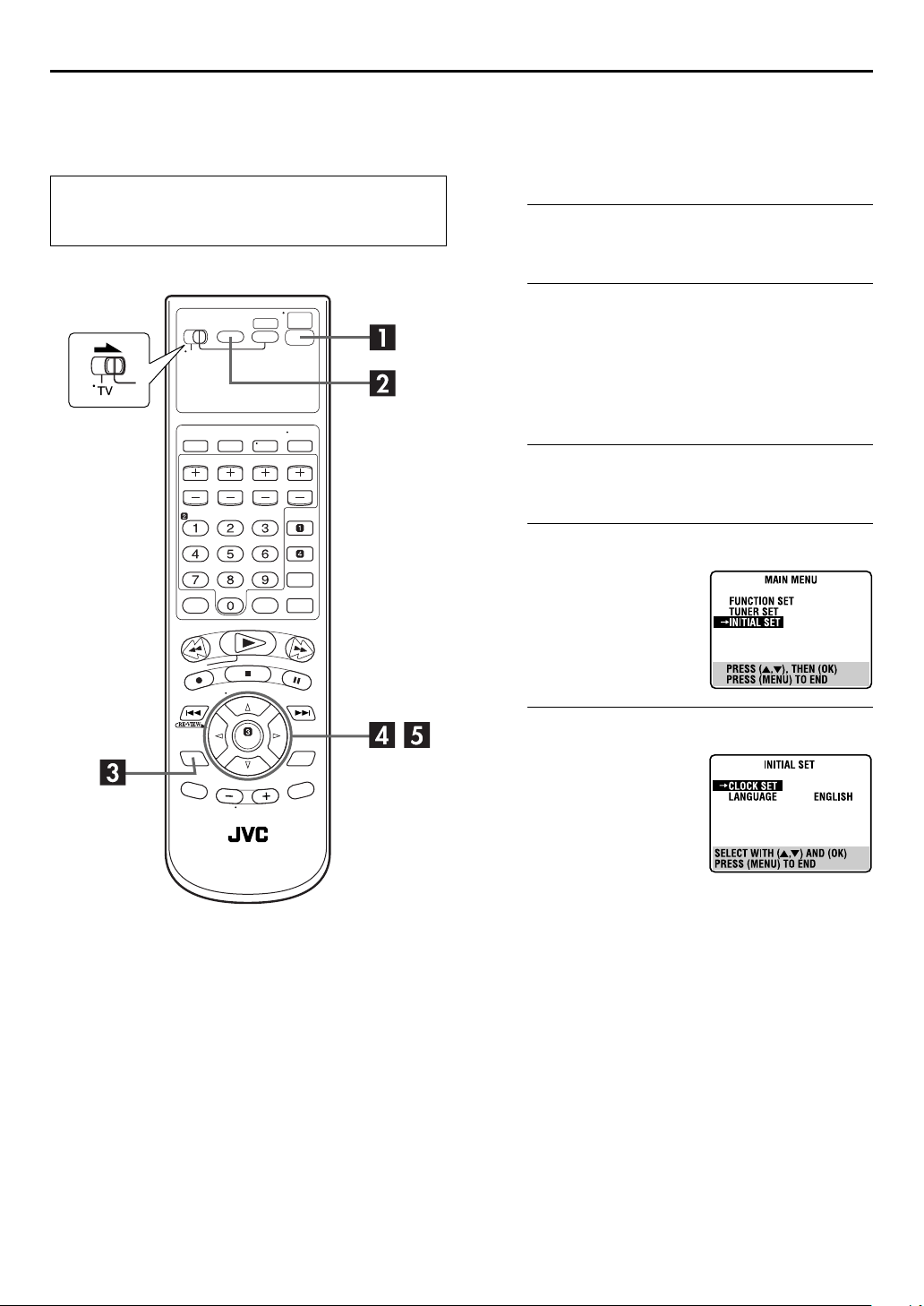
SET UP MENU
Press
D
Press rt to move the
highlight bar (arrow) to
“INITIAL SET”, then press OK
or e.
(1).
Select the VCR deck.
repeatedly so that the VCR indicator
so that the VCR indicator lights up.
Access the Main Menu screen.
.
Access the Initial Set screen.
Access the Clock Set screen.
E
Press rt to move the
highlight bar (arrow) to
“CLOCK SET”, then press OK
or e.
Page 5
EN
25
Semiauto Clock Set
You can change the host channel/D.S.T. (Daylight Saving Time)/
time zone setting manually. First follow steps A to E in
“Preparations” (
NOTE:
The time set previously will be erased when “AUTO CLOCK”,
“HOST CH”, “D.S.T.” or “TIME ZONE” setting is changed.
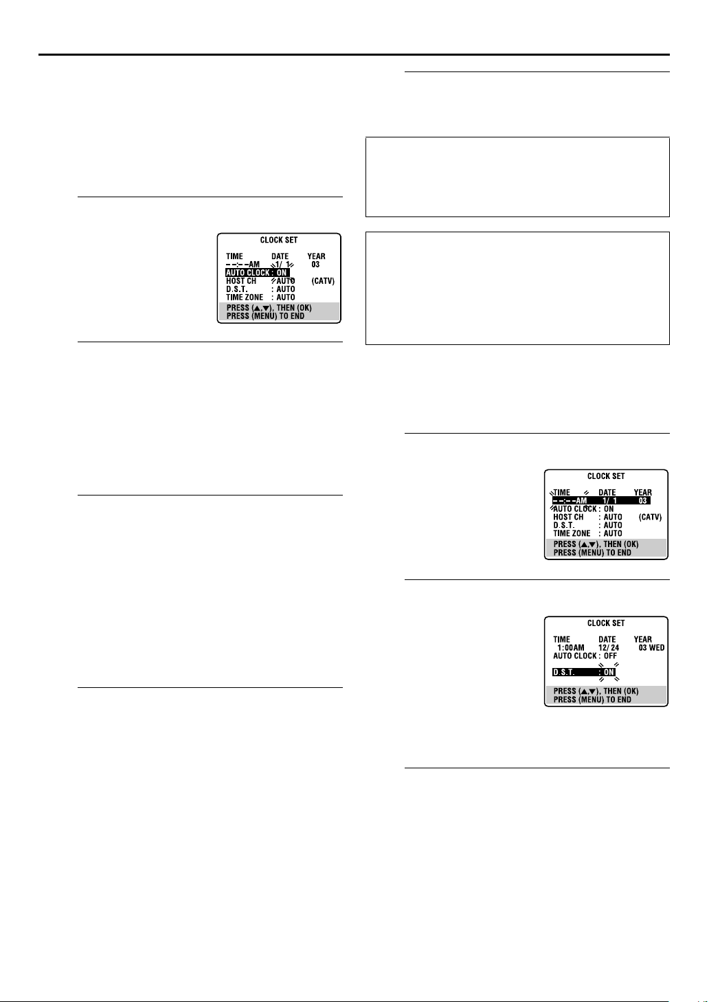
A
Press OK or e repeatedly to
move the highlight bar to
“AUTO CLOCK”, then press
so that “ON” is selected.
rt
B
You can either select “AUTO” or enter a PBS channel
number.
Press OK or e to move the highlight bar to “HOST CH”,
then press rt repeatedly until “AUTO” or the desired
PBS channel number is selected.
NOTE:
Some PBS channels do not transmit clock setting data.
C
Press OK or e to move the highlight bar to “D.S.T.”, then
press rt repeatedly until the desired setting is selected.
AUTO
: Select if you want to adjust your VCR’s clock
ON
: Adjustment will be made by the built-in clock
OFF
: Select when Daylight Saving Time does not apply
D
Press OK or e to move the highlight bar to “TIME
ZONE”, then press rt repeatedly until “AUTO” or the
desired time zone is selected. Each time you press the
button, the time zone changes as follows:
AUTO{ATL ANT IC{EASTERN{CENTRAL
{
MOUNTAIN{PACIFIC{ALASKA{HAWAII
(back to the beginning)
NOTE:
If an incorrect time is displayed by the Plug & Play function, you
may be receiving the clock setting data of a PBS channel from an
adjacent time zone or from an incorrect PBS channel from a
cable TV system. If you selected “AUTO” for the host channel in
step B, be sure to select the correct time zone manually.
墌
pg. 24), then go to the following steps.
Set “AUTO CLOCK” to “ON”.
Select the host channel.
Select the D.S.T. mode.
automatically by the incoming signal from the
host channel. Be sure to select the correct time
zone manually in step D.
itself.
to you.
Select the time zone.
{
{
Complete the Semiauto Clock Set.
E
SET UP MENU
Press
to return to normal screen.
IMPORTANT
Turn off the unit after performing Semiauto Clock. “AUTO”
will appear on the front display panel while the clock is
being set. The current clock time will appear automatically
when the clock setting is complete.
AUTO DAYLIGHT SAVING TIME
This function enables automatic adjustment of the unit’s
clock at the start and end of Daylight Saving Time.
With Auto DST activated, —
— on the first Sunday of April at 2:00 AM, the clock is
adjusted to 3:00 AM.
— on the last Sunday of October at 2:00 AM, the clock is
adjusted to 1:00 AM.
Manual Clock Set
First follow steps A to E in “Preparations” (墌pg. 24), then go
to the following steps.
Set time, date and year.
A
Press rt until the desired
time appears, then press OK
or e. Set the date and year in
the same way.
●
Holding rt changes the time
in 30-minute intervals, or
changes the date in 15-day
intervals.
Select D.S.T. mode.
B
Press OK or e to move the
highlight bar to “D.S.T.”, then
press rt to select the
desired setting.
ON
: Adjustment will be
made by the built-in
clock itself.
OFF
: Select when Daylight
Saving Time does not
apply to you.
Start clock.
C
SET UP MENU
Press
To make corrections any time during the process
Press OK or e repeatedly until the item you want to change
blinks, then press rt.
and normal screen appears.
Page 6
26
EN
Tuner Set
●
Turn on the TV and select the VCR channel (or AV
mode).
●
Slide the
TV/VCR/DVD
switch to the right.
INITIAL SETTINGS (cont.)
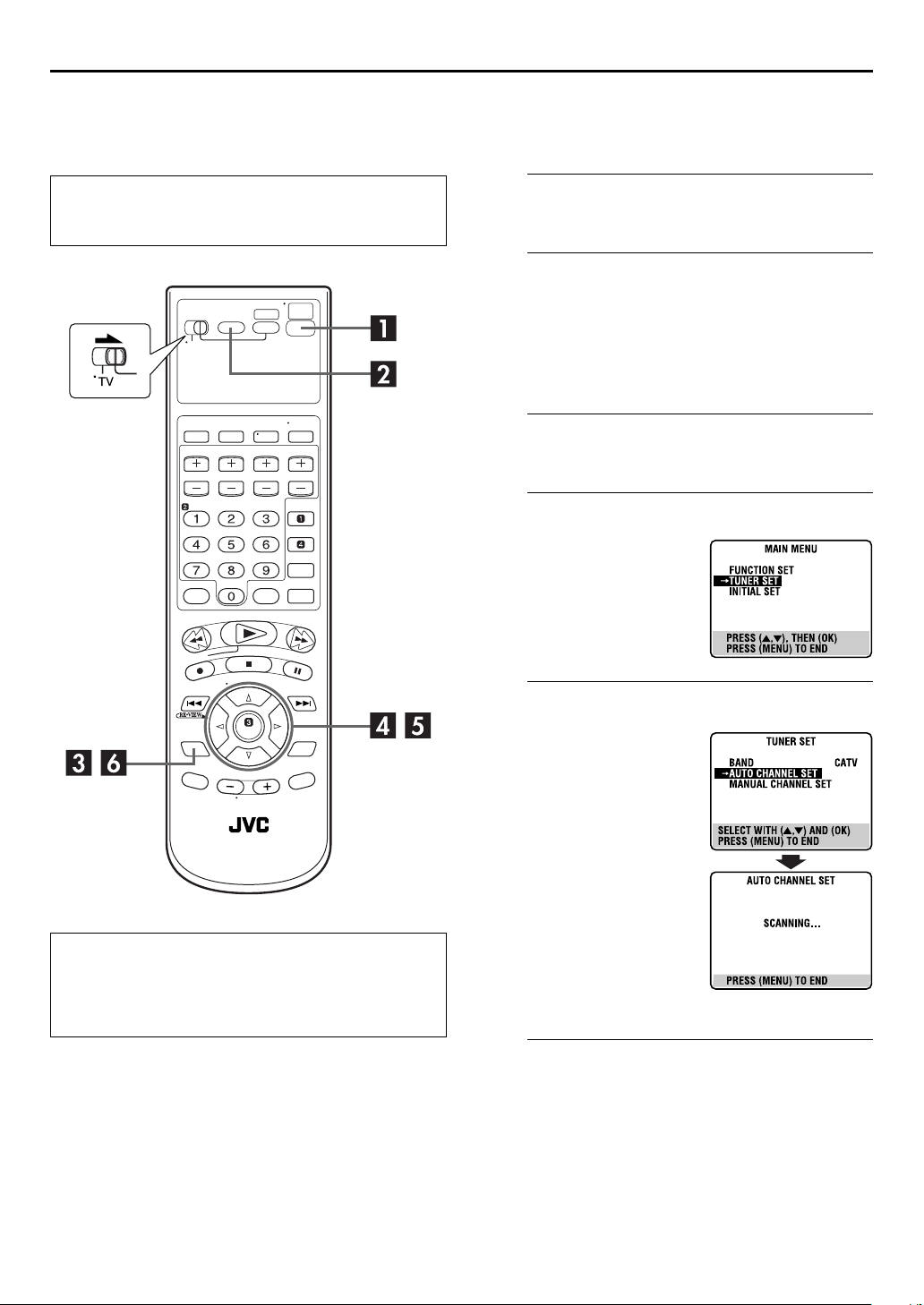
Auto Channel Set
Perform Auto Channel Set only if channels have not been set
correctly by the Plug&Play setting.
Turn on the unit.
A
POWER
Press
B
On the unit
VCR/DVD
Press
lights up.
On the Remote
VCR
Press
C
SET UP MENU
Press
D
Press rt to move the
highlight bar (arrow) to
“TUNER SET”, then press OK
or e.
(1).
Select the VCR deck.
repeatedly so that the VCR indicator
so that the VCR indicator lights up.
Access the Main Menu screen.
.
Access the Tuner Set screen.
INFORMATION
The unit selects the correct band (TV or CATV) automatically
during Auto Channel Set. The selected band will be
displayed on the right side of “BAND” on the Tuner Set
screen.
Perform Auto Channel Set.
E
Press rt to move the
highlight bar (arrow) to
“AUTO CHANNEL SET”, then
press OK or e. You can
automatically set the
receivable channels in your
area in the order of their
frequencies.
●
When Auto Channel Set is
complete, “SCAN
COMPLETED” appears on the
TV screen.
●
If the scan was unsuccessful,
“SCAN COMPLETED–NO
SIGNAL–” appears on screen.
Check the connections and start
again.
Return to the normal screen.
F
SET UP MENU
Press
.
Page 7
EN
27
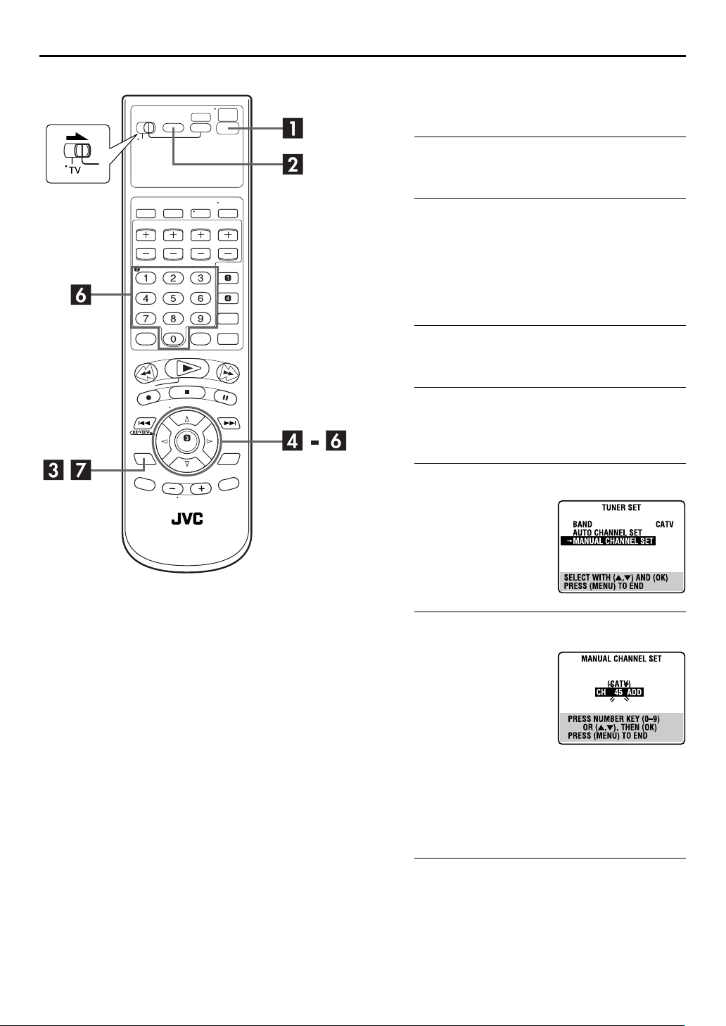
Manual Channel Set
You can add the channels you want or delete the channels you
do not want manually.
Turn on the unit.
A
POWER
Press
B
On the unit
VCR/DVD
Press
lights up.
On the Remote
VCR
Press
C
SET UP MENU
Press
D
Press rt to move the highlight bar (arrow) to “TUNER
SET”, then press OK or e.
(1).
Select the VCR deck.
repeatedly so that the VCR indicator
so that the VCR indicator lights up.
Access the Main Menu screen.
.
Access the Tuner Set screen.
Access the Manual Channel Set screen.
E
Press rt to move the
highlight bar (arrow) to
“MANUAL CHANNEL SET”,
then press OK or e.
Add or skip the desired channels.
F
To add channels
A
Press the
input a channel number you
want to add.
B
Press OK or e to set to
“ADD”.
C
Repeat A and B to add
other channels.
To skip channels
A
Press rt or the
number you want to skip.
B
Press OK or e to set to “SKIP”.
C
Repeat A and B to skip other channels.
G
Press
number keys
to
number keys
to select a channel
Return to the normal screen.
SET UP MENU
.
Page 8
)
28
EN
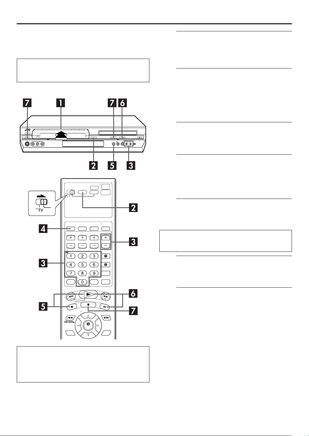
Basic Playback
●
Turn on the TV and select the VCR channel (or AV
mode).
●
Slide the
TV/VCR/DVD
switch to the right.
OPERATIONS ON VCR DECK
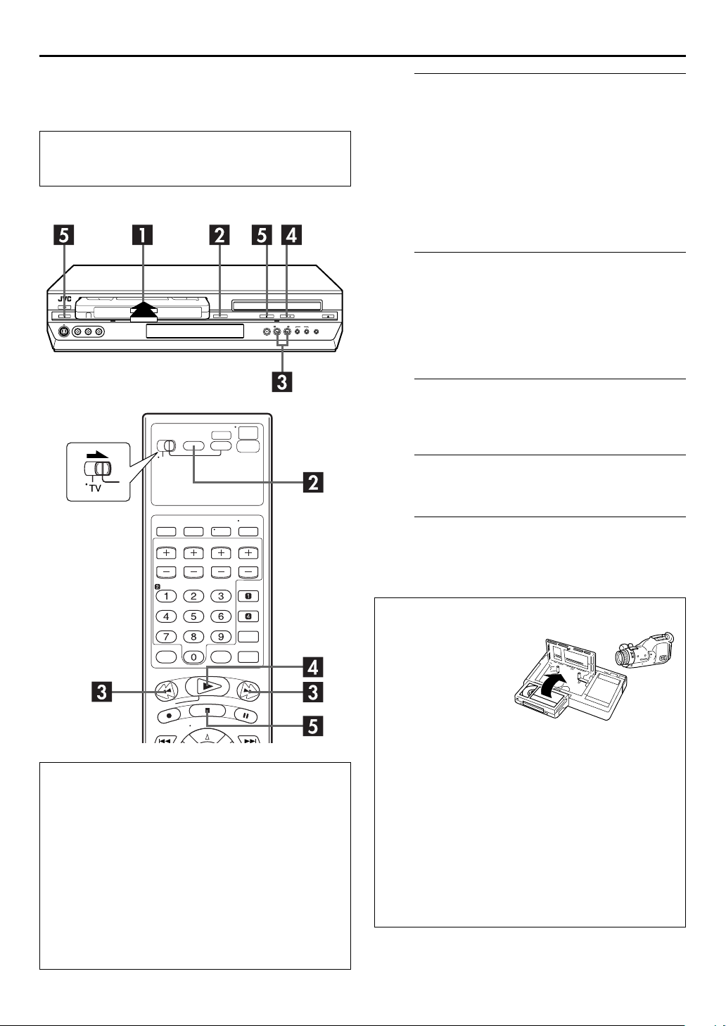
Load a cassette.
A
Make sure the window side is up, the rear label side is
facing you and the arrow on the front of the cassette is
pointed toward the unit.
●
Do not apply too much pressure when inserting.
●
If the record safety tab has been removed, playback begins
automatically. Although the DVD deck is selected, the VCR
deck is selected automatically if the DVD deck is in stop
mode.
●
The unit’s power comes on automatically and the counter is
reset to 0:00:00.
Select the VCR deck.
B
On the unit
VCR/DVD
Press
lights up.
On the Remote
VCR
Press
Find the program start point.
C
If the tape is advanced past the start point, press
(3). To go forward, press FF (5).
repeatedly so that the VCR indicator
so that the VCR indicator lights up.
REW
Clean the video heads using a dry cleaning
cassette — ECL-3F — when:
●
Rough, poor picture appears while a tape is played back.
●
The picture is unclear or no picture appears.
●
“USE CLEANING CASSETTE” appears on the screen (only
with “SUPERIMPOSE” set to “ON”). (
墌
pg. 77)
NOTE:
The heads get dirty in the following cases:
●
in an environment prone to extreme temperature or
humidity
●
in a dusty environment
●
flaw, dirt or mold on video tapes
●
continuous usage for a long time
Start playback.
D
PLAY
Press
E
Press
to remove the cassette.
(4).
Stop playback.
STOP
(8). Then press
EJECT
(x) on the VCR deck
Usable cassettes
Full-Size VHS
T-30 (ST-30**)
T-60 (ST-60**)
T90
T-120 (ST-120**)
T-160 (ST-160**)
ST-210**
Compact VHS*
TC-20 (ST-C20**)
TC-30 (ST-C30**)
TC-40 (ST-C40**)
* Compact VHS camcorder recordings can be played on
this unit. Simply place the recorded cassette into a VHS
Cassette Adapter and it can be used just like any full-sized
VHS cassette.
** This unit can record on regular VHS and Super VHS
cassettes. While only VHS signals can be recorded on
regular VHS cassettes , both VHS and Super VHS signals
can be recorded and played back using Super VHS
cassettes.
1) By using the S-VHS ET function, it is possible to record
and play back with S-VHS picture quality on VHS
cassettes with this unit.
1
Page 9
Playback Features
●
Turn on the TV and select the VCR channel (or AV
mode).
●
Slide the
TV/VCR/DVD
switch to the right.
EN
29
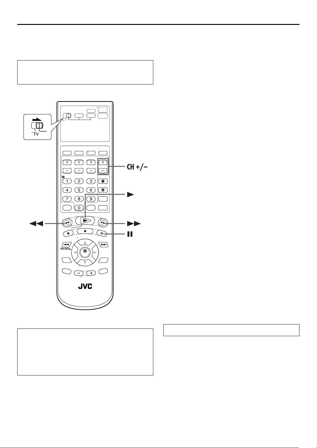
Still Picture/Frame-By-Frame
Playback
1
Pause during playback.
PAUSE
Press
●
If there is vertical jitter, press
the picture.
2
Activate frame-by-frame playback.
Press
(9).
PAUSE
(9) to advance a still picture.
CH +/–
on the Remote to correct
Slow Motion
1
Pause during playback.
PAUSE
Press
2
Activate slow motion playback.
Press and hold
Press
picture.
●
The speed changes for each direction by pressing
and FF (5) repeatedly.
NOTE:
During slow motion playback, some noise may appear on the TV
screen. Press
(9).
PAUSE
PAUSE
(9) and release again to return to still
CH +
(9) for 2 seconds, then release.
or – on the Remote to eliminate the noises.
REW
(3)
ATTENTION
In the search, still, slow-motion or frame-by-frame playback
mode,
●
the picture will be distorted.
●
the noise bars will appear.
●
there may be a loss of colour.
●
you cannot hear the sound.
Variable Speed Search
During playback, press FF (5) for forward variable
speed search, or
search.
●
The speed changes for each direction by pressing
and FF (5) repeatedly.
When pressing FF (5):
(SP): +5x{+7x
(EP): +11x{+21x
When pressing
REW
Once
normal playback speed. After this process, each press of
(3) changes the search speed between –5x and –7x in SP
mode, –11x and –21x in EP mode.
(SP): –1x]–5x{–7x
(EP): –1x]–11x{–21x
To resume normal playback, press
REW
(3) for reverse variable speed
REW
REW
(3) is pressed, reverse search starts in –1x
(3):
PLAY
(4).
(3)
REW
Page 10
30
EN
OPERATIONS ON VCR DECK (cont.)
x
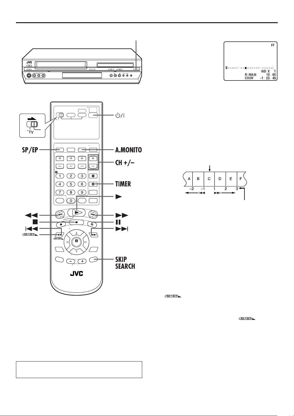
Index Search
Your unit automatically marks
index codes at the beginning of
each recording. This function gives
you quick access to any one of 9
index codes in either direction.
NOTE:
Before starting, make sure the unit
is in the Stop mode.
Activate Index Search.
INDEX
Press
“INDEX 1” is displayed on the TV screen and search
begins in the corresponding direction.
●
To access index codes 2 through 9, press
INDEX
displayed.
Example:
To locate the beginning of B from the current position, press
INDEX
To locate the beginning of D from the current position, press
INDEX
(2) or
(6) repeatedly until the correct index number is
(2) twice.
(6) once.
INDEX
(6). “INDEX –1” or
Current position
INDEX
(2) or
Skip Search
During playback, press
over unwanted sections.
Each press initiates a 30-second period of fast-motion
playback. Normal playback resumes automatically.
To resume normal playback during a Skip Search,
PLAY
press
(4).
SKIP SEARCH
1 to 6 times to skip
Index number
●
When the specified index code is located, playback begins
automatically.
Instant ReView
Simply by pressing a single button, the unit power comes on,
rewinds, and begins playback of the last timer-recorded
program. If you have several programs recorded, you can easily
access any of them.
NOTE:
Before starting, make sure that the unit is off and that the Timer
mode is disengaged.
Activate Instant ReView.
Press . The unit power comes on and the unit
searches for the index code indicating the start of the last
timer-recorded program. Once it’s found, playback begins
automatically.
●
To watch the first of the 3 programs, press three
times. The unit searches and begins playback automatically.
You can access a program as far as 9 index codes away from
the current tape position.
Page 11
EN
31
Next Function Memory
The Next Function Memory “tells” the unit what to do after
rewinding. Before continuing, make sure the unit is in the Stop
mode.
a-
For Automatic Start Of Playback
REW
Press
2 seconds.
b-
For Automatic Power Off
Press
2 seconds.
c-
For Automatic Timer Standby
Press
d-
For Automatic Cassette Ejection After Tape Rewind
Press
seconds.
(3), then press
REW
(3), then press
REW
(3), then press
REW
(3), then press
PLAY
(4) within
POWER
TIMER
EJECT
(1) within
within 2 seconds.
(x) within 2
Repeat Playback
Your unit can automatically play back the whole tape 100 times
repeatedly.
1
Start playback.
PLAY
Press
2
Press
●
The Play indicator ($) on the front display panel blinks slowly.
●
After playing back a tape 100 times, the unit stops
automatically.
3
Press
●
Pressing
stops Repeat Playback.
(4).
Activate Repeat Playback.
PLAY
(4) and hold for over 5 seconds, then release.
Stop Repeat Playback.
STOP
(8) at any time.
PLAY
(4),
REW
(3), FF (5) or
PAU SE
(9) also
Manual Tracking
Your unit is equipped with automatic tracking control. During
playback, you can override this and adjust the tracking manually
by pressing the CH buttons.
1
Override automatic tracking.
During playback, press SP/EP on the Remote.
2
Adjust the tracking manually.
CH +
Press
●
Press SP/EP again to return to automatic tracking.
or – on the Remote.
NOTE:
When a new tape is inserted, the unit enters the automatic
tracking mode automatically.
Soundtrack Selection
Your unit is capable of recording three soundtracks (HI-FI L,
HI-FI R and NORM) and will play back the one you select.
During Playback
Pressing
●
A.MONITOR
You can also select the soundtrack on the Function Set screen.
墌
pg. 75)
(
TRACK
On-Screen Display
H I-F I Hi-Fi sound is played back
H I-F I L
changes the soundtrack as follows:
USE
Sound on the left Hi-Fi channel is
played back
H I-F I R
NORM
NORM
H I-F I
Sound on the right Hi-Fi channel is
played back
Sound on the normal track is played
back
Both sounds on the Hi-Fi track and
normal track are mixed and played
back
NOTES:
●
“HIFI” should normally be selected. In this mode, Hi-Fi stereo
tapes are played back in stereo, and the normal audio track is
played back automatically for tapes with only normal audio.
●
“SUPERIMPOSE” must be set to “ON” or the on-screen
displays will not appear. (
墌
pg. 77)
Page 12
32
EN
Basic Recording
●
Turn on the TV and select the VCR channel (or AV
mode).
●
Slide the
TV/VCR/DVD
switch to the right.
OPERATIONS ON VCR DECK (cont.)
Load a cassette.
A
Insert a cassette with the record safety tab intact.
●
The unit’s power comes on automatically and the counter is
reset to 0:00:00.
Select the VCR deck.
B
On the unit
VCR/DVD
Press
lights up.
On the Remote
VCR
Press
Choose a program.
C
CH +/–
Press
you wish to record.
Set the tape speed.
D
Press SP/EP. The current setting appears on the front
display panel or TV screen. Press SP/EP again to change
the setting while the tape speed is displayed on the TV
screen.
repeatedly so that the VCR indicator
so that the VCR indicator lights up.
number keys
or the
to select the channel
Recording Resume Function
If there is a power outage during recording, Instant Timer
Recording or timer recording (
recording will resume automatically when power is restored
to the unit unless the unit’s memory backup has expired.
墌
pg. 32, 33, 36), the
Start recording.
E
Press and hold
Remote, or press
Video Calibration takes place at the beginning of both the
first SP and the first EP recording after inserting the cassette.
墌
pg. 35)
(
Pause/Resume recording.
F
PAUSE
Press
●
You can select channel during the Record Pause mode.
Stop recording.
G
STOP
Press
to remove the cassette.
REC
(7) and press
REC
(7) on the unit.
(9). Press
(8). Then press
PLAY
PLAY
(4) on the
(4) to resume recording.
EJECT
(x) on the VCR deck
Page 13
Recording Features
●
Turn on the TV and select the VCR channel (or AV
mode).
●
Slide the
TV/VCR/DVD
switch to the right.
EN
33
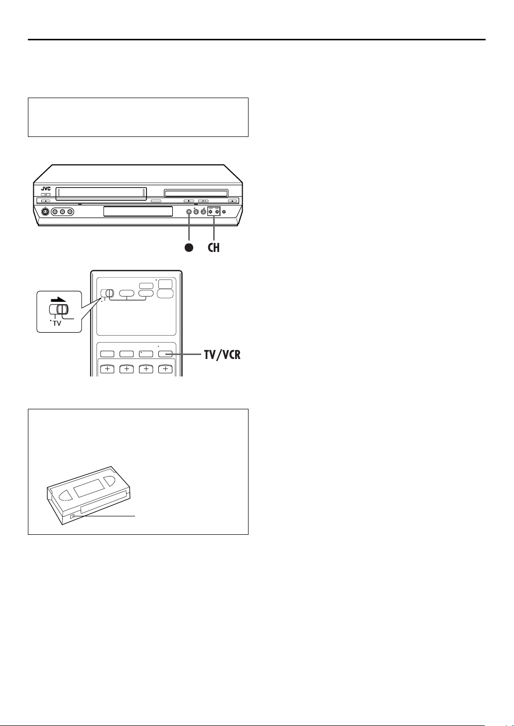
Record One Program While Watching
Another
If your unit is connected to the TV via the AV connection,
TV/VCR
press
display panel and the TV broadcast being recorded
disappear.
Once recording is in progress, all you need to do is to set
the channel controls on the TV for the station you wish to
view.
●
The program selected with the TV’s channel controls appears
on the TV screen, while the one selected with the unit’s CH
buttons is recorded on the tape.
. The unit’s VCR indicator on the front
NOTE:
You can also use the DVD deck in the following cases. Before
use, be sure to turn on the unit and select the DVD deck.
●
During recording
●
During timer recording
●
During timer standby mode
Instant Timer Recording (ITR)
This easy method lets you record for from 30 minutes to 6 hours
(selectable in 30-min. increments), and shuts the unit off after
recording is finished.
Accidental erasure prevention
To prevent accidental recording on a recorded cassette,
remove its safety tab. To record on it later, cover the hole
with adhesive tape.
Record safety tab
1
Start recording.
REC
Press
2
Press
the front display panel.
3
If you want to record for more than 30 minutes, press
REC
time by 30 minutes.
(7) on the unit.
Engage the ITR mode.
REC
(7) again. “䡬” blinks and “0:30” appears on
Set the recording duration.
(7) to extend the time. Each press extends recording
NOTES:
●
You can only perform ITR using the
unit’s front panel.
●
Still picture playback stops automatically after 5 minutes to
protect the heads.
●
When the end of the tape is reached during timer recording,
the unit stops and “
panel.
●
When the end of the tape is reached during timer recording or
Instant Timer Recording, the unit is turned off and “
“$” blink on the front display panel.
●
During Instant Timer Recording, any other timer programed
recording won’t start even if their start time has come. In such
a case, the timer programed recording starts (if the end time of
the timer programed recording is set after the end of Instant
Timer Recording) after the Instant Timer Recording finishes.
䡬
” and “$” blink on the front display
REC
(7) button on the
䡬
” and
Page 14
34
EN
OPERATIONS ON VCR DECK (cont.)
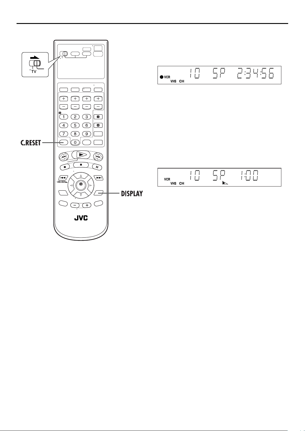
Elapsed Recording Time Indication
1
Set the counter display.
DISPLAY
Press
front display panel.
2
Reset the counter.
C.RESET
Press
●
The counter is reset to “0:00:00” and shows the exact elapsed
time as the tape runs. You can check the exact time of a
recording or playback.
until a counter reading appears on the
before starting recording or playback.
Tape Remaining Time
DISPLAY
Press
appears.
●
The front display panel shows the tape remaining time with
“z” displayed.
until the time remaining on the tape
●
By pressing the
show the clock time, counter reading or tape remaining time.
DISPLAY
button, you can change display to
NOTES:
●
When you press
the TV screen for 5 seconds, then the displays other than the
counter disappears. To clear the counter display, press
DISPLAY
●
Depending on the type of tape being used, the tape remaining
time reading may not appear right away, or is not correct.
“– –:––” may sometimes appear, or the display may blink on
occasion.
DISPLAY
.
, the on-screen display appears on
Second Audio Recording
This unit’s built-in MTS decoder enables reception of
Multichannel TV Sound broadcast. To record a SAP program
received, set “2ND AUDIO RECORD” to “ON”. (
NOTE:
When the channel is changed on the unit;
●
The “STEREO” indicator appears on the screen for about
5 seconds if the program is a stereo broadcast.
●
The “SAP” indicator appears on the screen for about 5 seconds
if the program is a SAP broadcast.
●
Both indicators appear when a stereo program is accompanied
by SAP sound.
墌
pg. 78)
Page 15
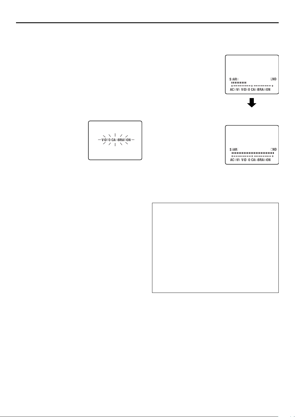
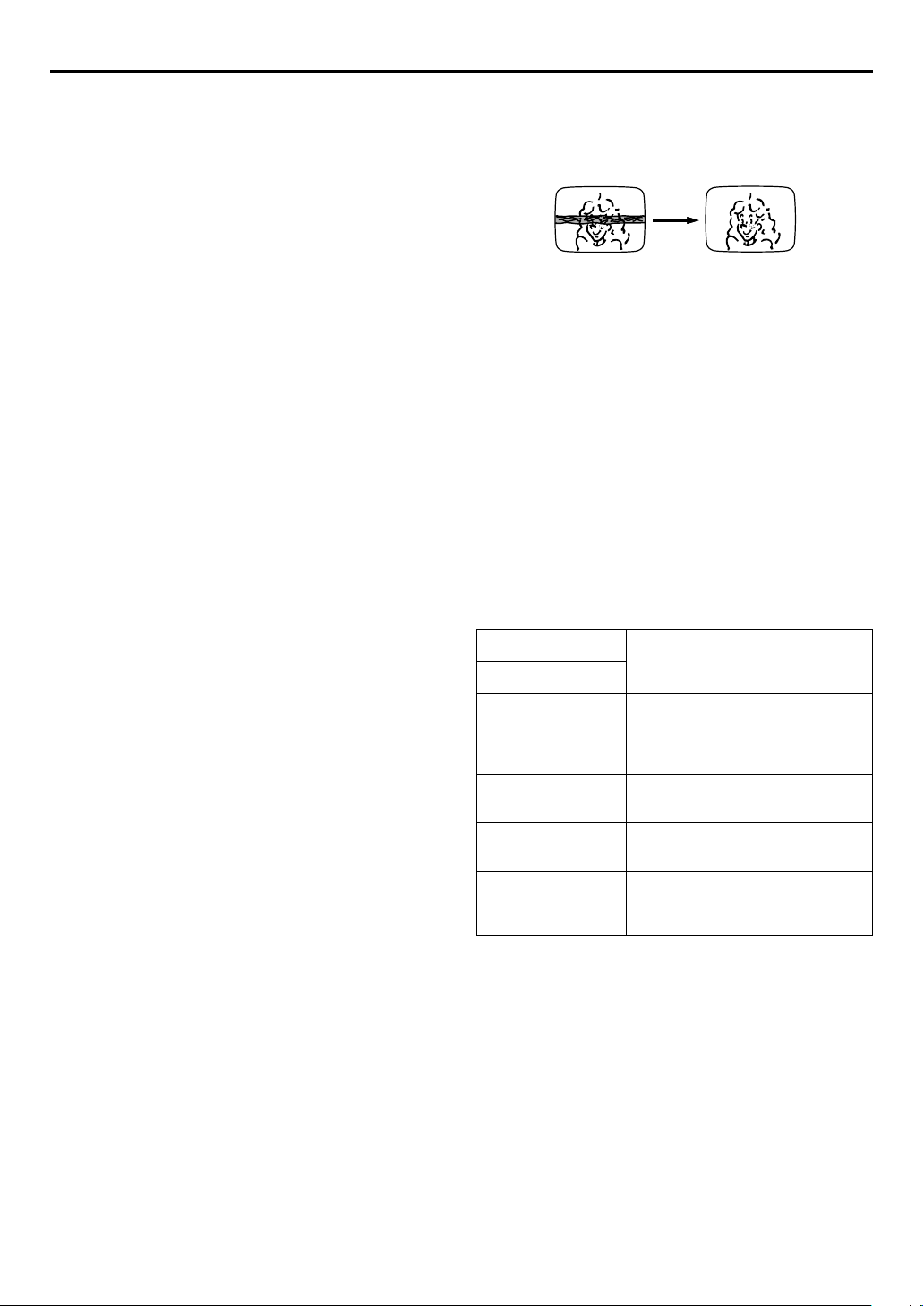
Active Video
Calibration
The Video Calibration checks the condition of the tape in
use during playback and recording, and compensates to
provide the highest-possible playback and recording
pictures. You can set “VIDEO CALIBRATION” to “ON” or
“OFF” to your preference. (墌pg. 76)
Playback
The unit assesses the quality
of the tape once you initiate
playback.
●
The unit adjusts the playback
picture quality based on the
quality of the tape in use.
●
Video Calibration is active
during automatic tracking. The
Video Calibration screen
appears blinking on the TV screen.
NOTES:
●
When watching a tape recorded with “VIDEO CALIBRATION”
set to “ON”, it is recommended that you leave VIDEO
CALIBRATION on during playback as well.
●
When watching a rental tape or one recorded on another VCR,
or when using this unit as the player for editing, set VIDEO
CALIBRATION to your preference. (
●
The Video Calibration only appears at the beginning of
automatic tracking. Even though it doesn’t appear after that,
the VIDEO CALIBRATION function is operative.
墌
pg. 76)
EN
Recording
The unit assesses the quality
of the tape once you initiate
recording.
●
The unit spends approximately
7 seconds assessing the
condition of the tape, then
begins recording.
NOTES:
●
The Video Calibration works for
both SP and EP modes only
after a tape has been inserted
and the Record mode is first
initiated. It does not work
during recording.
●
The Video Calibration does not
work while Satellite Auto
Recording is in progress.
墌
pg. 41)
(
●
In the case of timer recordings,
the Video Calibration works
before recording is initiated.
●
Once the cassette is ejected,
the Video Calibration data is
cancelled. The next time the
cassette is used for recording, Video Calibration is reperformed.
●
Pressing the unit’s
is displayed does not start Instant Timer Recording. (
REC
(7) button while the Video Calibration
ATTENTION
Since the Video Calibration works before recording actually
starts, there is a delay of approximately 7 seconds after
PLAY
(7) and
the unit is pressed. To make sure you record the desired
scene or program in its entirety, first perform the following
steps:
A
Press and hold
the Record Pause mode.
●
The unit then automatically checks the condition of the
tape and, after approximately 7 seconds, re-enters Record
Pause mode.
B
Press
If you want to bypass the Video Calibration and begin
recording immediately, set “VIDEO CALIBRATION” to
“OFF”. (
(4) on the Remote are pressed, or
PAUSE
(9) and press
PLAY
(4) to start recording.
墌
pg. 76)
DURING VIDEO
CALIBRATION
VIDEO CALIBRATION
COMPLETE
墌
REC
(7) on
REC
(7) to engage
35
pg. 33)
REC
Page 16
36
EN
Express Timer
Programing
Before performing Express Timer Programing:
●
Make sure that the unit’s built-in clock is set properly.
●
Insert a cassette with the safety tab in place. The unit will
come on automatically.
●
Turn on the TV and select the VCR channel (or AV mode).
●
Slide the
TV/VCR/DVD
switch to the right.
OPERATIONS ON VCR DECK (cont.)
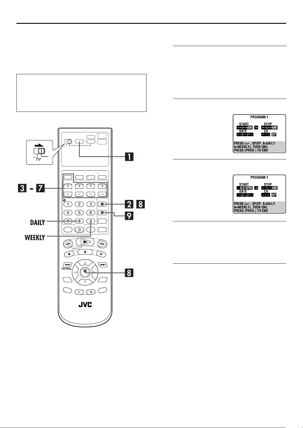
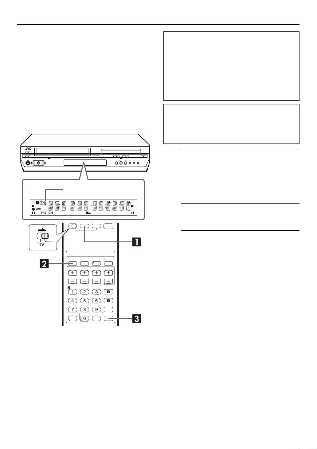
Example: To timer-record the program from 8:00 to
10:00 on 24th December, on channel 12.
Select the VCR deck.
A
On the unit
VCR/DVD
Press
lights up.
On the Remote
VCR
Press
Access the Program screen.
B
PROG.
Press
starting out, “P1” appears.)
Enter the program start time.
C
START +/–
Press
time you want recording to
start.
●
Press and hold
move in 30-minute
increments, or press and
release repeatedly to move
1 minute at a time.
repeatedly so that the VCR indicator
so that the VCR indicator lights up.
. (If you’re just
to enter the
START +/–
to
Enter the program stop time.
D
STOP +/–
Press
stop.
●
Press and hold
press and release repeatedly to move 1 minute at a time.
Enter the program date.
E
DATE +/–
Press
●
The current date appears on the TV screen. The date you enter
appears in its place.
to enter the time you want recording to
STOP +/–
.
to move in 30-minute increments, or
Page 17

EN
37
Enter the channel position.
F
CH +/–
Press
G
Press SP/EP.
H
Press
on the TV screen for about 5 seconds, then the normal
screen appears. If “PROGRAM NOT COMPLETED
PROGRAM OVERLAP” appears on the TV screen, see
page 40.
●
Repeat steps B–H for each additional program.
I
Press
appears on the front display panel.
●
To disengage the timer mode, press
To Timer-Record Weekly Or Daily Serials:
— anytime during stepsC through G, press
key “9”
serials (Monday – Friday). Either “WEEKLY” or “DAI LY” appears
on the TV screen. Pressing the button again makes the
corresponding indication disappear.
.
Set the tape speed.
Return to the normal screen.
PROG.
or OK. “PROGRAM COMPLETED” appears
Engage the unit’s timer mode.
TIMER
. The unit turns off automatically and “#”
TIMER
again.
) for weekly serials or
DAI LY (number key “8”
WEEKLY (number
) for daily
NOTES:
●
You can program this unit to timer-record as many as 8
programs. If you try to program the unit to record a ninth,
“PROGRAM FULL” appears on the TV screen. To record the
extra program, you must first cancel any unnecessary
programs. (
●
In case of a power failure after programing, the unit’s memory
backup keeps your selections for approximately 5 seconds.
●
Programs that start after midnight must have the next day’s
date.
Cable Box or DBS Receiver Users
To timer-record a satellite broadcast using Express Timer
Programing:
A
B
C
墌
pg. 39)
Perform steps A–I. In stepF, enter “F-1” or “L-1” for
the channel position depending on the connector being
used.
Set the DBS receiver to the appropriate channel before
the selected program begins.
Leave the DBS receiver’s power on.
Page 18
38
EN
OPERATIONS ON VCR DECK (cont.)
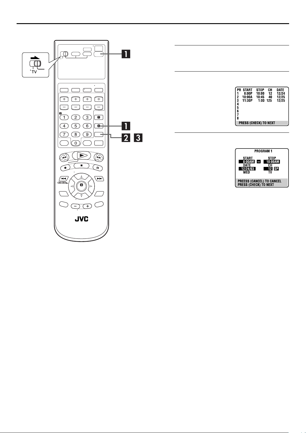
Check, cancel and change programs
Disengage the timer mode.
A
TIMER
Press
B
Press
C
Press
to check more information.
Each time you press
PROG. CHECK
program’s information
appears.
, then press
Access the Program Check screen.
PROG. CHECK
Access the Program screen.
PROG. CHECK
, the next
POWER
.
again
(1).
Page 19

EN
39
To cancel or change a program
Cancel or change a program.
D
CANCEL
Press
settings, press the appropriate button:
STOP +/–, DATE +/–, CH +/–, DAI LY (number key “8”
WEEKLY (number key “9”
E
PROG. CHECK
Press
are still some programs remaining, go on to stepF.
F
TIMER
Press
to cancel a program. To change program
START +/–
) and/or SP/EP.
Return to the normal screen.
as many times as necessary. If there
Return to the timer mode.
.
,
),
Page 20
40
A
EN
OPERATIONS ON VCR DECK (cont.)
When programs overlap each other
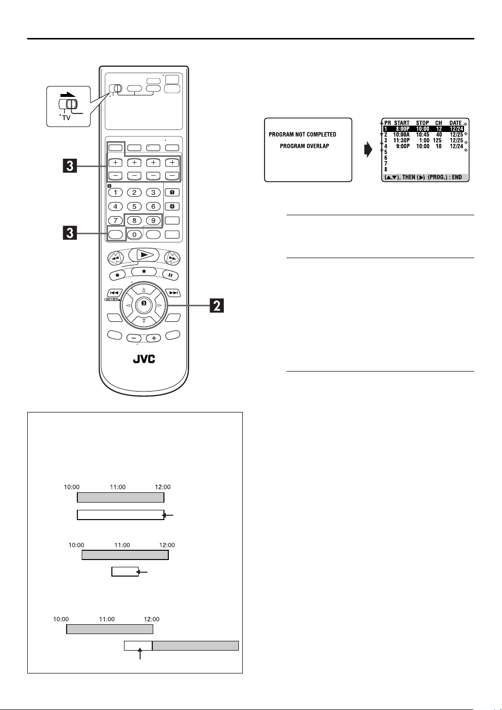
If “PROGRAM NOT COMPLETED PROGRAM OVERLAP”
appears, you have another program overlapping the program
you have just made.
The Program Check screen appears and conflicting programs
will start blinking.
Example: Program 1 (you have just made) and Program 4
overlap each other.
Confirm the overlapping programs.
A
Overlapping programs blink on the TV screen.
Select the program to modify.
B
Press rt, then press OK or e.
●
You can only select one of the overlapping programs.
TTENTION
If there is a conflict in the timer schedule and one
program overlaps with another, only the parts shown
below in gray will be recorded.
Pattern 1:
Program 1
Program 2
Pattern 2:
Program 1
Pattern 3:
The program with the lower program number
will be recorded.
CH10
CH40
The program starting earlier will be recorded.
CH10
Program 2
The program starting earlier will be recorded,
followed by the remaining portion of the other
program.
CH40
Not recorded
Not recorded
NOTE:
If you do not mind this overlap, press
program setting. The program with the lower program number
will be recorded and the other one will not be recorded
correctly. If no changes are made for approximately 1 minute,
the unit will return to the normal screen.
Cancel or change program setting.
C
To cancel a program,
screen you do not want is shown. “PROGRAM
COMPLETED” appears on the TV screen for about
5 seconds, then the normal screen appears.
To change a program,
START +/–, STOP +/–, DATE +/–, CH +/–, DAILY
number key “8”
(
EP
when the Program screen on which you want to make
changes is shown, then press OK. “PROGRAM
COMPLETED” appears on the TV screen for about
5 seconds, then the normal screen appears.
press
press the appropriate button:
WEEKLY (number key “9”
),
PROG.
CANCEL
to finish the timer
when the Program
) and/or SP/
NOTE:
If the overlap is not yet solved, or another overlap occurs with
the timer program setting after making the last correction on a
program, the conflicting programs will be shown on the Program
Check screen again. Repeat the above steps again until the
overlap is solved.
Program 1
CH10
Program 2
CH40
Not recorded
Page 21
Satellite Auto
Recording
This function allows you to automatically record a
satellite program which is timer-programed on your
external DBS receiver. Connect a DBS receiver to the
unit’s AUDIO/VIDEO INPUT (L-1) connectors and
program the timer on the DBS receiver. The unit starts or
stops recording by the signals input from the DBS
receiver. After recording, the unit’s power shuts off
automatically.
●
You can also connect the cable box if it has a timer.
“N” indicator
EN
ATTENTION
●
Be sure not to turn on the DBS receiver before the program
is executed; otherwise, the unit will start recording when
the DBS receiver’s power is turned on.
●
If you have connected another appliance other than a DBS
receiver to the AUDIO/VIDEO INPUT (L-1) connectors, be
sure not to engage the Satellite Auto Recording mode;
otherwise, the unit will start recording when the connected
appliance’s power is turned on.
●
Satellite Auto Recording and timer-recording cannot be
done at the same time.
Before performing the following steps:
●
Make sure the DBS receiver is connected to the unit’s
AUDIO/VIDEO INPUT (L-1) connectors.
●
Program the timer on the DBS receiver.
●
Insert a cassette with the safety tab in place.
●
Slide the
A
On the unit
Press
lights up.
On the Remote
Press
TV/VCR/DVD
switch to the right.
Select the VCR deck.
VCR/DVD
VCR
repeatedly so that the VCR indicator
so that the VCR indicator lights up.
41
Set the tape speed.
B
Press SP/EP.
Engage the Satellite Auto Recording mode.
C
Press and hold
and “#” indicators light up and the unit turns off
automatically.
REC LINK
for about 2 seconds. The “N”
NOTES:
●
To disengage the Satellite Auto Recording mode, press
●
If the unit’s power is off, it is not possible to engage the Satellite Auto Recording mode.
●
In stepC, if the “N” indicator does not light but instead blinks quickly even though your DBS receiver’s power is off, Satellite Auto
Recording will not work properly with that DBS receiver*. If this is the case, perform “Express Timer Programing” (
timer-record a satellite program.
* Some DBS receivers output signals even if the power is off. Satellite Auto Recording is not possible with those DBS receivers.
●
The “N” indicator blinks while Satellite Auto Recording is in progress.
●
For timer programing of the DBS receiver, refer to the instruction manual of the DBS receiver.
●
Satellite Auto Recording is not possible if your DBS receiver does not have a timer.
●
Pressing the unit’s
Satellite Auto Recording mode.
●
If there are more than one satellite programs you wish to record with Satellite Auto Recording, it is not possible to set different tape
speeds for each program.
●
Depending on the type of DBS receiver, the unit may not record a slight portion of the beginning of the program or may record
slightly longer than the actual length of the program.
●
If you engage the Satellite Auto Recording mode when the DBS receiver’s power is on, the unit will not start Satellite Auto Recording
even though the “N” and “#” indicators blink. When the DBS receiver shuts off once and is turned back on again, the unit starts
recording.
●
You can also record a program from your cable system in the same way if the system has a timer.
POWER
(1) button while Satellite Auto Recording is in progress turns off the unit’s power and disengages the
REC LINK
. The “N” indicator goes off.
墌
pg. 36) to
Page 22

42
EN
OPERATIONS ON DVD DECK
To play back a MP3/WMA/JPEG disc, see pages 62 – 67.
Basic Playback
●
Turn on the TV and select the VCR channel (or AV
mode).
●
Slide the
TV/VCR/DVD
switch to the right.
Load the disc.
A
A
●
B
●
C
●
●
B
On the unit
Press
lights up.
On the Remote
Press
C
Press
Example: DVD VIDEO
OPEN/CLOSE
Press
disc tray.
The unit’s power comes on automatically.
Place the disc in the disc tray.
For details, refer to “Placing a Disc” (
OPEN/CLOSE
Press
disc tray.
Pressing
Playback begins automatically if the auto-playback DVD disc
is loaded. Although the VCR deck is selected, the DVD deck is
selected automatically if the VCR deck is in stop mode.
PLAY
(4) also close the disc tray.
(x) on the DVD deck to open the
墌
(x) on the DVD deck to close the
pg. 9).
Select the DVD deck.
VCR/DVD
DVD
repeatedly so that the DVD indicator
so that the DVD indicator lights up.
Start playback.
PLAY
(4).
ATTENTION
●
You can not use the DVD deck when the VCR deck is in
the Automatic Satellite Recording standby and recording
mode.
●
You can use the DVD deck when the VCR deck is in the
timer standby mode.
Title number Chapter
●
It may take a few seconds to start playback.
●
If you load a DVD disc whose region code does not match the
DVD deck, “REGION CODE ERROR!” appears on the TV
screen. For details, refer to “Region Number” (
●
With Video CD discs with PBC control or some DVD discs, the
menu display may appear on the TV screen after starting
playback. In this case, select an item which you want to play
back from the menu. Otherwise, the playback cannot go
forward. Refer to “Locating a desired scene using the menu of
the Video CD with PBC” (
scene using the DVD menu” (
Pause playback.
D
PAUSE
Press
●
To resume normal playback, press
E
Press
deck to open the disc tray, then remove the disc.
●
Pressing
you stop playback. For details, see “Resume Function” on
page 45.
(9).
Stop playback.
STOP
(8). Press
PLAY
number
墌
pg. 43) or “Locating a desired
墌
OPEN/CLOSE
(4) resume playback from the position where
Elapsed time
pg. 43).
PLAY
(4).
(x) on the DVD
墌
pg. 7).
NOTE:
When you press
the unit’s power comes on and the disc tray opens automatically.
OPEN/CLOSE
(x) while the unit is turned off,
Page 23
Playback Features
●
Turn on the TV and select the VCR channel (or AV
mode).
●
Slide the
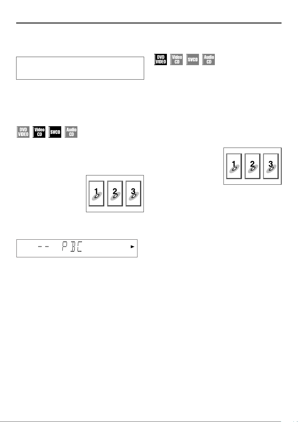
Playback Control (PBC) Function
— Locating a desired scene using the
menu of the Video CD with PBC
Some Video CD discs supports the PBC function. PBC is an
abbreviation of “PlayBack Control.” A Video CD disc recorded
with PBC has its own menus, such as a list of the songs of the
disc. You can locate a specific scene by using the menu.
1
Access the PBC menu.
In stop mode
Press
●
Depending on a disc, PBC
menu may automatically
appear on the TV screen by
simply loading a disc on the
unit.
During playback
Press
●
“PBC” appears on the front
display panel.
2
Start playback.
Press the appropriate
●
The unit starts playback of the selected item.
●
When “NEXT” or “PREVIOUS” appears on the TV screen:
Pressing
Pressing
●
You can return to the menu by pressing
●
The method of the operation is different depending on the
disc.
PLAY
(4).
RETURN
SKIP
SKIP
TV/VCR/DVD
.
(6) advances to the next page.
(2) returns to the previous page.
switch to the right.
number keys
.
RETURN
.
EN
43
Locating a desired scene using the
DVD menu
DVD VIDEO discs may have two types of the menus; top menu
and disc menu.
Top menu
DVD discs generally have their own menus which show the disc
contents. These menus contain various items such as titles of a
movie, names of songs, or artist information. You can locate a
desired scene by using the top menu displayed on the TV screen.
TOP MENU
Press
Disc menu
DVD discs have the disc menu to select subtitle and audio
language etc. for each title.
MENU
Press
1
Access the DVD menu.
TOP MENU
Press
2
Start playback.
Press
rt w e
●
It may be possible to select the desired item using the
keys
depending on the disc.
NOTES:
●
When “X” appears on the TV screen in step1, the disc does
not have a top menu or disc menu.
●
Top menu or disc menu may not appear depending on the
discs even if it is recorded in DVD VIDEO format and
finalized. In that case, press
number of titles on a disc, then press the appropriate
keys
to select the desired title.
to access the top menu.
to access the disc menu.
MENU
or
to select a desired item, then press OK.
.
Example:
STOP
(8) to display the total
number
number
NOTES:
●
If you want to playback a PBC-compatible Video CD disc
without activating the PBC function, start playback by using
number keys
the
●
To activate the PBC function when a PBC-compatible Video
CD disc is being played back without the PBC function, press
TOP MENU
“RESUME” is set to “ON”) then press
instead of the
MENU
or
, or press
PLAY
(4) button.
STOP
(8) (press twice when
PLAY
(4).
Page 24
44
EN
OPERATIONS ON DVD DECK (cont.)
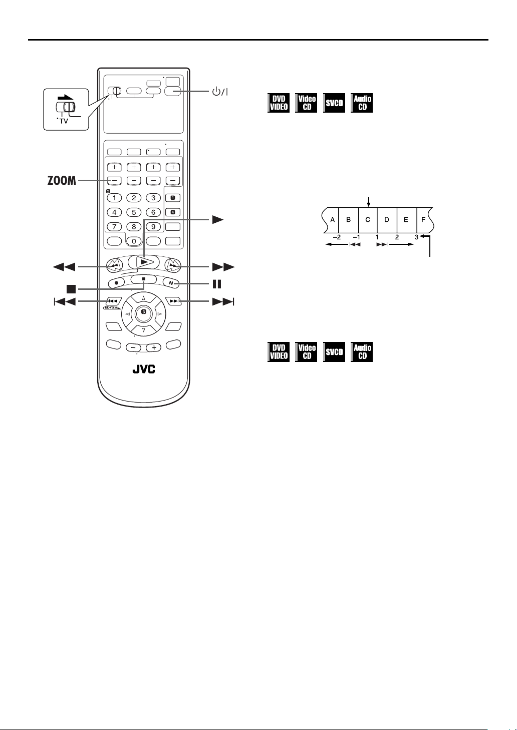
Locating the start point of the item or
skip the item
SKIP
Press
Example:
To locate the beginning of item B from the current position, press
SKIP
To locate the beginning of item D from the current position,
press
●
When the specified item is located, playback begins
automatically.
(2) or
(2) twice.
SKIP
(6) once.
SKIP
(6) during playback.
Current position
The number you press the
button
Variable Speed Search
During playback, press FF (5) for forward variable
speed search, or
search.
●
The more times you press, the faster the playback picture
moves.
●
To resume normal playback, press
OR
During playback, press and hold
variable speed search, or press and hold
reverse variable speed search.
●
While you press and hold the button, the image is played back
at 5x speed.
●
To resume normal playback, release
REW
(3) for reverse variable speed
PLAY
(4).
SKIP
(6) for forward
SKIP
SKIP
(2) or
(2) for
SKIP
(6).
NOTES:
●
Actual speed may be different from that displayed on the TV
screen depending on the discs.
●
Playback sound is not heard in any variable speed search
mode other than in 1.5x speed search mode.
●
During 1.5x speed search of a DVD VIDEO disc, you can hear
the played back audio converted into Linear PCM format in
stereo. In such a case, the pitch and sound quality may change
depending on the disc.
●
In case of DVD VIDEO discs formatted in DTS format, SVCD
or Audio CD discs, playback sound is not heard during 1.5x
speed search.
●
When switching to 1.5x speed search during variable speed
Search, first press
press FF (5).
PLAY
(4) to return to normal playback, then
Page 25
Still Picture/Frame-By-Frame
Playback
1
Pause during playback.
Press
PAUSE (9
2
Activate frame-by-frame playback.
Press
PAUSE (9
● To resume normal playback, press
).
) to advance a still picture.
PLAY
(4).
Slow Motion
During playback, press
for reverse slow motion playback, or FF (5) for forward
slow motion playback.
● Each press of FF (5) changes the playback speed as follows:
1/32]1/16]1/4]1/2
● Each press of
follows (only for DVD VIDEO discs):
–1/32]–1/16]–1/4]–1/2
● To resume normal playback, press
REW
PAUSE (9
(3) changes the playback speed as
NOTES:
● Reverse slow motion playback is possible only with the DVD
VIDEO discs.
● This function may not works for some Video CD or SVCD.
), then press
(4).
PLAY
REW (3
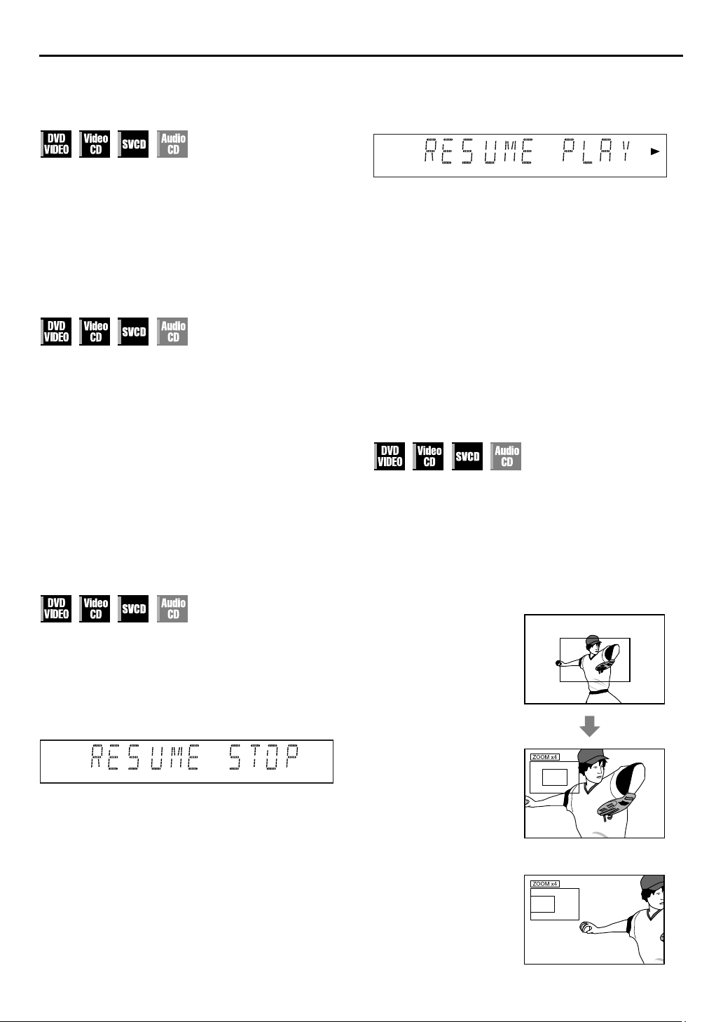
Resume Function
It is possible to memorize the position where you stop playback
and resume playback from that position.
● Be sure to set “RESUME” to “ON” or “DISC RESUME”.
pg. 83)
(
墌
2
Resume playback.
Press
PLAY (4
point.
● “RESUME PLAY” appears on the front display panel.
). The unit start playback from the resume
NOTES:
● Resume Function does not work on the Audio CD. It also may
not work depending on the discs.
● If you stop the playback of a disc for which an resume point
has already been memorized, the memory will be updated
with the new resume point.
● After the unit has memorized the resume point for 30 discs,
remembering a new resume point will cause the unit to delete
the oldest memorized point. Stopping playback of a disc for
which a resume point is already stored may change the order
in which the points are stored. This may potentially change the
order in which points are deleted.
● When the unit memorizes a resume point for a disc, it also
)
remembers audio language, subtitle and angle settings.
● This function may not works for some Video CD or SVCD.
Zooming
Press
● Each press of
1.8x]4x]8x]16x]32x]64x
● When a 16:9 aspect picture source is displayed on a 4:3
aspect TV (conventional TV) in Letter Box conversion mode,
the margins in black shown on top and bottom of the TV
screen will be cropped by selecting 1.8x magnification. In
such a case, note that both left and right side parts of the
picture will also be cropped.
● While zoomed, the picture may look coarse or distorted.
during playback or while paused.
ZOOM
Current magnification
changes the magnification as follows:
ZOOM
EN
45
1
Memorize the resume point.
Press
STOP (8
● “RESUME STOP” appears on the front display panel.
● The unit enters Resume Stop mode and memorise the position
where you stop playback as the resume point.
● The unit retains a memory of the resume points of the last 30
discs played back, even though they have been ejected if
“RESUME” is set to “DISC RESUME”. (
● To clear the resume point:
When “RESUME” is set to “ON”:
•Press
•Press
• Eject the disc.
When “RESUME” is set to “DISC RESUME”:
• Set “RESUME” to “OFF”. (
•Press
) during playback.
(8) in stop mode.
STOP
(1) to turn off the unit.
POWER
(8) in stop mode.
STOP
墌
pg. 83)
墌
pg. 83)
Zoomed-in area
Press
rt w e
● To resume normal playback, press OK.
to move the zoomed-in scene.
Page 26
46
EN
OPERATIONS ON DVD DECK (cont.)
●
Each time you press we, the setting changes as follows:
NONE]ACTION]DRAMA]THEATER](Back to the
beginning)
NONE
: No effect
ACTION
: Suitable for action movies and sports
programs in which sounds dynamically
DRAMA
THEATER
●
The selection menu disappears automatically if you do not
change the selection for 10 seconds.
3
Select the effect level.
Press rt to select the desired effect level. (level 1 to 5)
●
To resume normal playback, press
move.
: Provides the natural and warm sound. You
can enjoy movies in a relaxed mood.
: You can enjoy sound effects like in a major
theater.
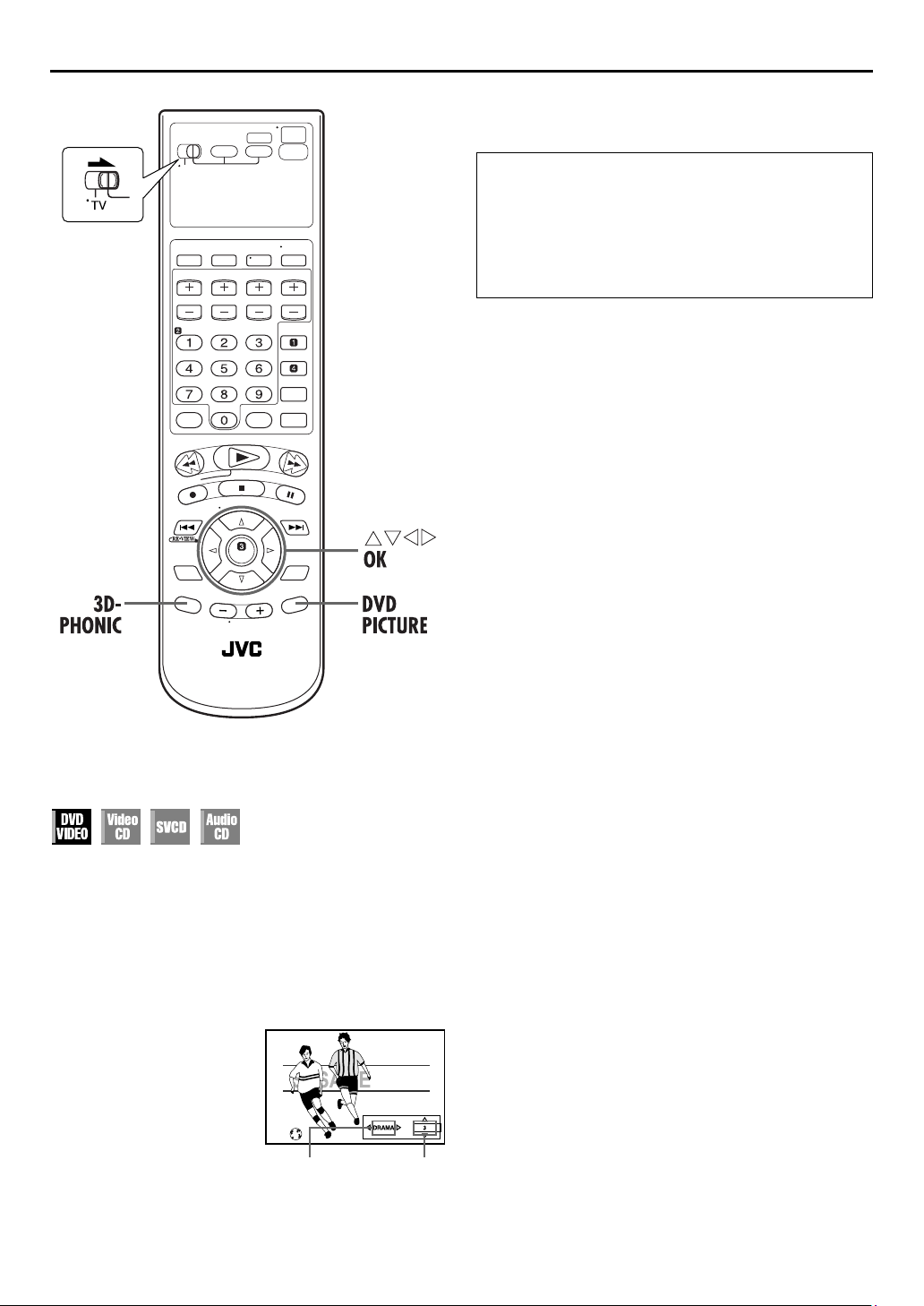
3D-PHONIC
.
NOTES:
●
The 3D Phonic function works correctly only when playing
back a DVD VIDEO disc recorded in the Dolby Digital format.
With other sources, you cannot get any effect if you activate
3D Phonic function.
●
When playing back a DVD VIDEO disc recorded with the
Dolby Digital that does not contain the rear signal, you cannot
get a correct 3D Phonic sound even if you activate 3D Phonic
function.
●
The 3D Phonic function does not affect the Dolby Digital
bitstream signal from the DIGITAL AUDIO OUT connector.
●
When 3D Phonic function is activated, Analog Down Mix and
D. Range Control functions are disabled. (
墌
pg. 82)
3D Phonic
3D Phonic function allows you to get a simulated surround
effect from your stereo system. You can enjoy the vertical
surround sound with your 2-channel stereo system.
1
Access the selection menu.
3D-PHONIC
Press
●
The current setting appears on the right bottom corner of the
TV screen.
2
Select the mode.
Press we repeatedly, then
press OK.
during playback.
Selected mode Effect level
Page 27

VFP function
— Adjusting the picture quality
EN
47
4
Select the parameter.
Press rt repeatedly to select a parameter you want to
adjust, then press OK.
●
Adjust gradually and confirm picture appearance results are as
preferred.
The VFP (Video Fine Processor) function enables you to adjust
the picture character according to the type of programing,
picture tone or personal preference.
NOTE:
Before you start operation;
The VFP setting screen disappears if no operations are done for
more than about 10 seconds. If the setting screen disappears
before you finish, start from step 1 again.
1
Access the VFP setting menu.
DVD PICTU RE
Press
playback.
●
The current setting appears on
the TV screen.
2
Select the VFP mode.
Press we repeatedly.
●
Each time you press we, the VFP mode changes as follows:
NORMAL]CINEMA]USER 1]USER 2](Back to the
beginning)
NORMAL
CINEMA
USER 1
USER 2
: Select this normally.
: Suitable for movie.
/
:
during
NORMAL
GAMMA
BRIGHTNESS
CONTRAST
SATURATION
TINT
SHARPNESS
Y DELAY
+
0
+
0
+
0
+
0
+
0
+
3
+
0
You can adjust parameters that affect picture
appearance and store settings. Go to step 3.
GAMMA
(–4 to +4):
Controls brightness of neutral tints while
maintaining brightness of dark and bright
portions.
BRIGHTNESS
Controls screen brightness.
(–16 to +16):
CONTRAST
Controls screen contrast.
(–16 to +16):
SATURATION
Controls screen color depth.
(–16 to +16):
TINT
Controls screen tint.
(–16 to +16):
SHARPNESS
Controls screen sharpness.
(+0 to +3):
Y DELAY
Controls screen color gap.
(–2 to +2):
●
VFP menu disappears and the following pop-up window
appears on the TV screen.
+
0
+
0
GAMMA
5
Adjust the parameter.
GAMMA
Press rt repeatedly to change the setting, then press
OK
.
●
The current VFP settings appear again.
NOTE:
You cannot adjust the parameters of “NORMAL” and “CINEMA”.
To adjust picture appearance manually
3
Access USER menu.
Press we repeatedly to
select “USER 1” or “USER 2”.
USER 1
GAMMA
BRIGHTNESS
CONTRAST
SATURATION
TINT
SHARPNESS
Y DELAY
+
0
+
0
+
0
+
0
+
0
+
3
+
0
6
Adjust the other parameters.
Repeat steps 4 and 5 to adjust other parameters.
To return to the normal screen
DVD PICTURE
Press
.
To activate your setting
DVD PICTURE
Press
, then press we repeatedly to select
“USER 1” or “USER 2” that you have changed the
parameters.
Page 28

48
EN
Using the on-
OPERATIONS ON DVD DECK (cont.)
How to Access the on-screen bar
PLAY SETUP
Press
twice whenever a disc is loaded.
screen bar
You can check disc information while the disc is loaded and you
can use some functions using the on-screen bar. The on-screen
bar allows you the various playback operations.
Example: During DVD VIDEO playback
Example: During Video CD playback
Contents of the on-screen bar during playback
DVD
Video CD
A
Disc type
B
Current transfer rate (Megabits per second)
C
Current title (for DVD)
D
Current chapter number (for DVD) or track number
(for other type of discs)
E
Time information (
F
Playback status
: appears during playback.
/ : appears during fast forward/reverse.
/ : appears during playback in forward slow-
motion/reverse slow-motion.
: appears when paused.
: appears when stopped.
G
Select this to change time information. (See 5 in the
illustration above) (
H
Select this for Repeat Playback. (
I
Select this for time search function. (墌pg. 51)
J
Select this for chapter search function. (墌pg. 52)
K
Select this to change audio language or channel.
墌
pg. 56, 57)
(
L
Select this to change subtitle language. (
M
Select this to change view angle. (
N
Select this for Program Playback. (
O
Select this for Random Playback. (
墌
墌
pg. 49)
pg. 49)
墌
墌
墌
墌
pg. 50)
墌
pg. 55)
pg. 53)
pg. 53)
pg. 54)
Page 29
EN
49
Basic operation on the on-screen bar
Example: When selecting the Repeat mode of DVD
During playback or while stopped
Access the on-screen bar.
A
PLAY SETUP
Press
the TV screen.
●
The currently selected item is highlighted.
Select menu item.
B
Press we to move 0 to , then press OK. The
pop-up window appears under the selected item.
●
The current setting appears.
Select the option.
C
Press rt to select the desired option, then press OK.
●
Each time you press rt, the options change.
To clear the on-screen bar
PLAY SETUP
Press
NOTE:
See the corresponding pages for details on each function.
twice. The on-screen bar appears on
.
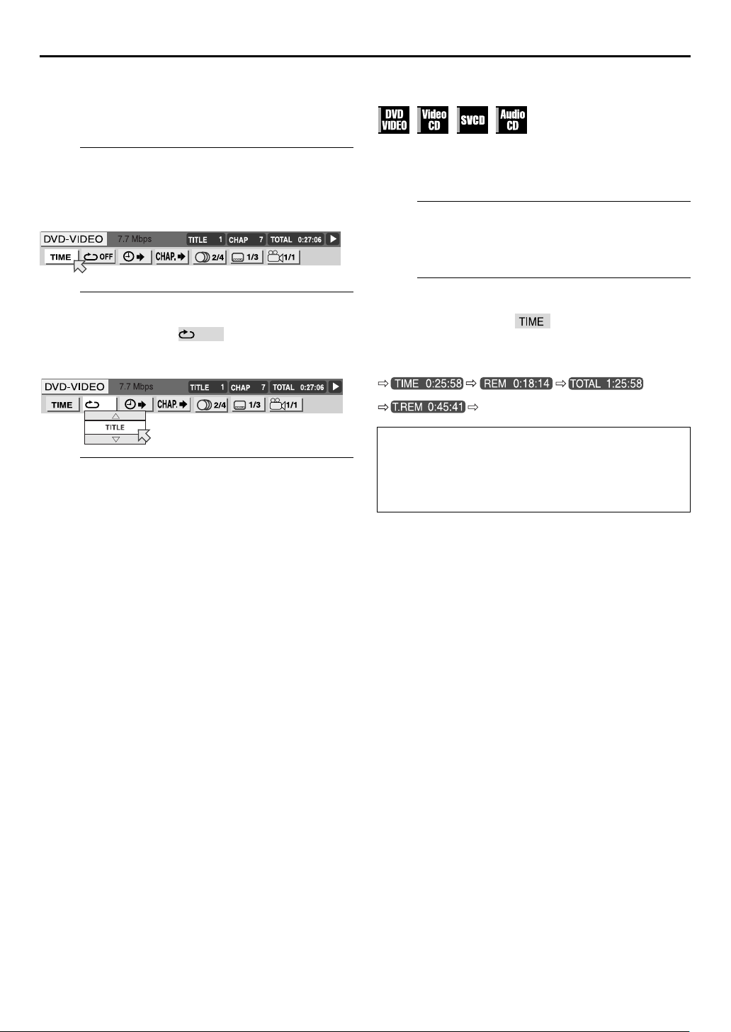
Change the time information
You can change the time information in the on-screen bar on the
TV screen and the front display panel of the unit.
During playback or while stopped
Access the on-screen bar.
A
PLAY SETUP
Press
the TV screen.
Select menu item.
B
Press we to move 0 to then press OK.
●
Each time you press OK, the time information changes as
follows;
Example: During DVD playback
TIME
: Elapsed playing time of current chapter/track
REM
: Remaining time of current chapter/track
TOTAL
: Elapsed time of title/disc
T. R EM
: Remaining time of title/disc
To clear the on-screen bar
PLAY SETUP
Press
NOTES:
●
While playing a Video CD, Audio CD or SVCD, the hour digit
indication does not appear.
●
While a DVD is stopped, “– – : ––” appears in the time
information display.
twice. The on-screen bar appears on
(Back to the beginning)
.
Page 30
50
EN
OPERATIONS ON DVD DECK (cont.)
Select the repeat mode.
C
Press rt repeatedly to select the Repeat mode, then
press OK.
●
The mode changes as follows:
DVD VIDEO
CHAPTER]TITLE]A-B]OFF](Back to the beginning)
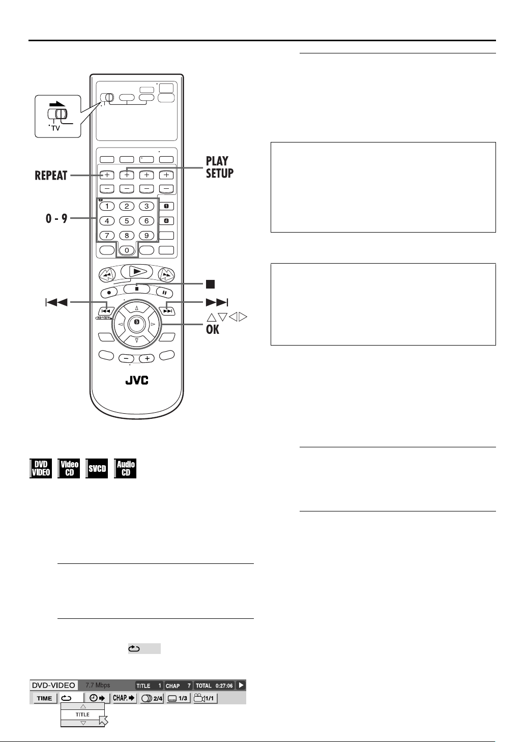
Repeat Playback
CHAPTER
TITLE
A-B
OFF:
Video CD/SVCD/CD
TRACK]ALL]A-B]OFF](Back to the beginning)
TRACK
ALL
A-B
OFF:
●
“A-B” cannot be selected while stopped.
To clear the on-screen bar
Press
To cancel Repeat Playback
Repeat from step A, select “OFF” in step C, then press
OK
When using the REPEAT button:
: The current chapter is played back
: The current title is played back
:
:
:
:
PLAY SETUP
.
repeatedly.
repeatedly.
The desired part is played back
repeatedly. (
Each title and chapter is played
back once.
The current track is played back
repeatedly.
All tracks are played back
repeatedly.
The desired part is played back
repeatedly. (
Each track is played back once.
.
墌
墌
pg. 51)
pg. 51)
You can repeat playback as you like according to the type of
disc.
DVD VIDEO: during playback
Audio CD: during playback or in stop mode
Video CD/SVCD: in stop mode or during playback with PBC
When using the on-screen bar
Access the on-screen bar.
A
PLAY SETUP
Press
the TV screen.
Select menu item.
B
Press we to move 0 to , then press OK.
●
The following pop-up window appears under the selected
item.
disactivated
twice. The on-screen bar appears on
Access the repeat mode.
A
REPEAT
Press
repeat.
●
Repeat mode is displayed on the TV.
B
Press
mode, then press OK.
●
To stop Repeat Playback, press
●
To cancel Repeat Playback, press
“OFF” appears on the TV screen, then press OK.
during playback of the item you want to
Select the repeat mode.
REPEAT
repeatedly to select the desired repeat
STOP
(8).
REPEAT
repeatedly until
NOTES:
●
Repeat Playback is not possible with a Video CD and SVCD
with PBC function.
●
Repeat Playback may not work properly depending on the
type of disc being used.
●
You cannot select A-B Repeat Playback by pressing
REPEAT
.
Page 31

EN
51
A-B Repeat Playback
You can repeat the desired part.
Access the on-screen bar.
A
PLAY SETUP
Press
the TV screen.
Select menu item.
B
Press we to move 0 to , then press OK.
●
The following pop-up window appears under the selected
item.
Select the repeat mode.
C
Press rt repeatedly to select “A-B”.
Select the start point.
D
Press OK at the beginning of the part you want to repeat
(point A).
●
The following display appears in the on-screen bar.
Select the end point
E
Press OK at the end of the part you want to repeat (point B).
●
A-B Repeat Playback starts. The selected part of the disc
(between point A and B) is played repeatedly.
To cancel A-B Repeat Playback
Repeat from step A, select “OFF” in step C, then press
OK
.
●
You can also cancel Repeat Playback by pressing
SKIP
or
(6).
To clear the on-screen bar
PLAY SETUP
Press
NOTES:
●
A-B Repeat Playback may not work properly depending on the
type of disc being used.
●
The subtitles recorded around A-B point may not appear.
●
The end of the item will be set as “B” point if the end of the
item reached before you set the “B” point.
●
When playing back a DVD, A-B Repeat Playback is possible
only within the same title.
●
“A-B” cannot be selected during Program and Random
Playback.
●
“A-B” cannot be selected while stopped.
twice. The on-screen bar appears on
SKIP
(2)
.
Time Search
You can play back a disc from the desired point by specifying the
elapsed time from the beginning of the current title (for DVD
VIDEO) or the disc (for Audio CD/Video CD) using the Time
Search.
When a PBC-compatible Video CD is played back, be sure to
inactivate PBC function before you perform Time search by
pressing the
you start playback.
A
Press
the TV screen.
B
Press we to move 0 to , then press OK.
●
The following pop-up window appears under the selected
item.
C
Press the
OK
Example:
To play back from a point 2 (hours): 34 (minutes): 08 (seconds)
elapsed
If you have specified a wrong selection,
Press w repeatedly until the wrong number is erased,
then press
●
The unit starts playback from the specified time.
To clear the on-screen bar
Press
NOTES:
●
When “X” is displayed on the TV screen in stepC, you have
selected a point that excesses the recording time of the disc.
●
Some DVD VIDEO discs do not contain time information, and
it is no possible to use the Time Search function. In such a
case, “X” is displayed on the TV screen as well.
●
Time Search does not work while you play back the Video CD
or SVCD with the PBC Function.
Reactivate the Playback Control (PBC) Function
You can reactivate the PBC function when you play back a PBCcompatible Video CD disc without PBC function.
●
Press
number keys
instead of the
Access the on-screen bar.
PLAY SETUP
twice. The on-screen bar appears on
Select menu item.
Select the time.
number keys
.
TIME _ : _ _ : _ _
TIME : _ : _ _TIME 2 : 3 _ : _ _
TIME : : _TIME 2 : 3 4 : 0 _
number keys
PLAY SETUP
TOP MENU
(0-9) to enter the time, then press
Press 2
Press 4
Press 8
to enter the correct numbers.
.
during playback.
PLAY
(4) button when
TIME : _ _ : _ _TIME 2 : _ _ : _ _
TIME : : _ _TIME 2 : 3 4 : _ _
TIME 2 : 3 4 : 0 8
Press 3
Press 0
Page 32

52
EN
OPERATIONS ON DVD DECK (cont.)
Chapter Search
You can start playback the desired chapter using the on-screen
bar.
Access the on-screen bar.
A
PLAY SETUP
Press
the TV screen.
Select menu item.
B
Press we to move 0 to , then press OK.
●
The following pop-up window appears under the selected
item.
Select the chapter.
C
Press the
number, then press OK.
●
number keys
The unit starts playback from the selected chapter.
twice. The on-screen bar appears on
(0-10) to enter the desired chapter
Examples:
To select track 5, press the
To select track 15, press the
To select track 25, press
●
It is not possible to use the
If you have specified a wrong selection
Enter the appropriate
To clear the on-screen bar
PLAY SETUP
Press
number key “5”
number key “1”
number key “2”
number keys
.
.
and
“5”
number key “+10”
and
again.
“5”
.
.
NOTES:
●
When “X” is displayed on the TV screen in stepC, the
chapter you have selected is not contained in the disc, or
chapter search does not work on the disc.
●
Chapter Search starts automatically when you select the
desired chapter in stepC depending on the disc.
.
Page 33

EN
53
Program Playback
You can play back up to 99 tracks in the desired order.
Access the on-screen bar.
A
Press
PLAY SETUP
Select the menu item.
B
Press we to move 0 to , then press OK.
● The program table appears under the on-screen bar.
Select the tracks in the desired order.
C
Press the appropriate
number keys
tracks.
twice in stop mode.
to select the
Program time
Random Playback
You can play back all the tracks on the disc in random order.
Access the on-screen bar.
A
Press
PLAY SETUP
Select the menu item.
B
Press we to move 0 to , then press OK.
● Playback starts in random order.
● To stop and quit Random Playback, press
● To cancel Random playback, repeat step B during Random
Playback. Normal playback resumes at the current point.
To clear the on-screen bar
Press
PLAY SETUP
NOTES:
● The same track will not be played back more than once during
Random Playback.
● Random playback is canceled when all the tracks have been
played back.
twice in stop mode.
.
STOP
(8).
Examples:
● To select track 5, press the
● To select track 15, press the
● To select track 25, press
.
“5”
If you have specified a wrong selection
Press
D
Press
● When all of the programed tracks have been played back,
Program Playback stops, but the programed information
remains.
● To stop Program Playback, press
● To clear all the programed tracks, press
playback and press
then press
● During Program Playback, pressing
selection of the program. Pressing
beginning of the current selection.
To clear the program table
Press
(8). The last selection programed is erased.
STOP
Start playback.
PLAY (4
PLAY SETUP
). Playback starts in the selected order.
PLAY SETUP
(8) again.
STOP
.
number key “5”
number key “+10”
number key “+10”
STOP
to clear the program table,
SKIP
SKIP
.
and
twice, then
(8).
STOP
(6) skip to the next
(2) returns to the
“5”
(8) to stop
.
NOTE:
Program Playback is not possible depending on the type of disc.
Page 34

54
EN
OPERATIONS ON DVD DECK (cont.)
Select the subtitle language.
C
Press rt repeatedly to select the desired subtitle
language, then press OK.
●
Each time you press the button, the subtitle language changes.
To clear the on-screen bar
PLAY SETUP
Press
.
NOTES:
●
For DVD VIDEO
Some subtitle languages are abbreviated in the pop-up
window. See “Language Code List” (
●
For SVCD
SVCD can contain up to four subtitles. Pressing
changes the subtitles regardless of whether the subtitles are
recorded or not. (Subtitles will not change if no subtitle is
recorded.)
●
When “X” appears on the TV screen in stepC, subtitle
language is not recorded.
When using the SUB TITLE button:
Access the menu.
A
SUB TITLE
Press
●
The following pop-up window appears on the TV screen.
.
墌
pg. 23).
SUB TITLE
Subtitle Selection
You can select subtitle language.
●
During playback
When using the on-screen bar
Access the on-screen bar.
A
PLAY SETUP
Press
the TV screen.
Select menu item.
B
Press we to move 0 to , then press OK.
●
The following pop-up window appears under the selected
item.
Example (DVD):“ENGLISH” is selected out of 3 subtitle
twice. The on-screen bar appears on
languages recorded.
Example (DVD):“ENGLISH” is selected out of 3 subtitle
B
Press rt or
subtitle language, then press OK.
●
Each time you press the button, the subtitle language changes.
●
The pop-up window disappears if no operation is done for
about 5 seconds.
languages recorded.
Select the subtitle language.
SUB TITLE
repeatedly to select the desired
NOTE:
When “X” appears on the TV screen in stepB, subtitle language
is not recorded.
Page 35

EN
55
Angle Selection
You can enjoy a variety of scene angles if the DVD VIDEO disc
contains “multi-angle” parts, where multiple cameras were used
to shoot the same scene from different angles.
If the disc contains “multi-angle” parts, “” appears on the TV
screen at the beginning of the “multi-angle” part when “ON
SCREEN GUIDE” is set to “ON”.
●
During playback
When using the on-screen bar
Access the on-screen bar.
A
PLAY SETUP
Press
the TV screen.
Select menu item.
B
Press we to move 0 to , then press OK.
●
The following pop-up window appears under the selected
item.
Example: The first view angle is selected out of 3 view angles
recorded.
twice. The on-screen bar appears on
When using the ANGLE button:
Access the menu.
A
ANGLE
Press
●
The following pop-up window appears on the TV screen.
Example:The first view angle is selected out of 3 view angles
B
Press rt or
view angle, then press OK.
●
Each time you press the button, the angle of the scene
changes.
●
The pop-up window disappears if no operation is done for
about 5 seconds.
Example:
1/3]2/3]3/3
.
recorded.
Select the view angle.
ANGLE
repeatedly to select the desired
(Back to the beginning)
]
1 1
1
Select the view angle.
C
Press rt repeatedly to select the desired view angle,
then press OK.
●
Each time you press the button, the angle of the scene
changes.
To clear the on-screen bar
PLAY SETUP
Press
.
NOTE:
When “X” appears on the TV screen in stepC, the current
scene is not recorded from multiple angles.
1
Page 36

56
EN
OPERATIONS ON DVD DECK (cont.)
Select menu item.
B
Press we to move 0 to , then press OK.
●
The following pop-up window appears under the selected
item.
Example:“ENGLISH” is selected out of 4 audio languages
C
Press rt repeatedly to select the desired audio
language, then press OK.
●
To clear the on-screen bar
Press
recorded.
Select the audio language.
Each time you press the button, the audio language changes.
PLAY SETUP
.
NOTES:
●
Some audio languages are abbreviated in the pop-up window.
See “Language Code List” (
●
If “X” appears on the TV, the current scene does not contain
plural audio languages.
When using the A.MONITOR button:
墌
pg. 23)
Audio Language Selection
Some DVD discs contain the multiple audio.
You can select the audio language of movies (DVD VIDEO).
●
During playback
When using the on-screen bar
Access the on-screen bar.
A
PLAY SETUP
Press
the TV screen.
twice. The on-screen bar appears on
Access the menu.
A
A.MONITOR
Press
●
The following pop-up window appears on the TV screen.
Example: “ENGLISH” is selected out of 3 audio languages
B
Press rt or
desired audio language, then press OK.
●
●
recorded.
Select the audio language.
Each time you press the button, the audio language changes.
The pop-up window disappears if no operation is done for
about 5 seconds.
.
A.MONITOR
repeatedly to select the
NOTE:
Some audio languages are abbreviated in the pop-up window.
See “Language Code List” (
墌
pg. 23).
Page 37

EN
57
Audio Channel Selection
When you play certain karaoke (DVD/Video CD/SVCD), you can
enjoy karaoke by selecting the audio channel to play.
●
The sound of each audio channel depends on the contents of
the disc.
●
During playback
When using the on-screen bar
Access the on-screen bar.
A
PLAY SETUP
Press
the TV screen.
Select menu item.
B
Press we to move 0 to , then press OK.
●
The following pop-up window appears under the selected
item.
Example: “ST” (stereo) is selected.
Select the audio channel.
C
Press rt repeatedly to select the desired audio channel,
then press OK.
●
Each time you press the button, the audio channel changes.
To clear the on-screen bar
PLAY SETUP
Press
twice. The on-screen bar appears on
.
When using the A.MONITOR button:
Access the menu.
A
A.MONITOR
Press
●
The following pop-up window appears on the TV screen.
Example:“ST” (stereo) is selected out of 3 audio channels
B
Press rt or
desired audio channel, then press OK.
●
●
For Video CD
ST]L]R](Back to the beginning)
For SVCD
ST 1]ST 2]L 1]R 1]L 2]R 2](Back to the beginning)
recorded.
Select the audio channel.
Each time you press the button, the audio channel changes.
The pop-up window disappears if no operation is done for
about 5 seconds.
To listen to normal stereo playback.
ST
:
To listen to L (left) audio channel only.
L
:
To listen to R (right) audio channel only.
R:
ST 1/ST 2
L 1/L 2
R 1/R 2:
:
:
.
A.MONITOR
To listen to normal stereo playback of ST 1 or
ST 2 channel.
To listen to the L (left) 1 or 2 audio channel.
To listen to the R (right) 1 or 2 audio channel.
repeatedly to select the
Page 38

58
EN
Parental Lock
This function restricts playback of DVD VIDEO discs which
contain violent (and other) scenes according to the level set by
the user. For example, if a movie which includes violent scenes
supports the parental lock feature, such scenes which you do not
want to let children view can be cut or replaced with other
scenes.
Turn on the TV and select the VCR channel (or AV
●
mode).
Slide the
●
TV/VCR/DVD
switch to the right.
OPERATIONS ON DVD DECK (cont.)
Access the DVD Set Up menu.
C
Press
A
B
D
SET UP MENU
Press we to select “ OTHERS”.
Access the “PARENTAL LOCK“ menu.
Press rt repeatedly to
move 0 to “PARENTAL
LOCK“, then press OK.
● The “PARENTAL LOCK“ submenu appears on the TV
screen.
● It is possible to access the
“PARENTAL LOCK“ menu only
in the stop mode when a DVD
disc is loaded on the unit.
Access the country code menu.
E
Press rt repeatedly to
move 0 to “COUNTRY
CODE“, then press OK.
.
PARENTAL LOCK
COUNTRY CODE
SET LEVEL
PASSWORD
EXIT
SELECT
USE TO SELECT USE OK TO CONFIRM
TO EXIT PRESS [SET UP MENU]
OK
US
NONE
To set Parental Lock for the first time
Turn on the unit.
A
Press
POWER (1
Select the DVD deck.
B
On the unit
Press
VCR/DVD
lights up.
On the Remote
Press
DVD
).
repeatedly so that the DVD indicator
so that the DVD indicator lights up.
Select the country code.
F
Press rt repeatedly to
move 0 to select the country
code, then press OK.
● See “Country/Area Code List
for Parental Lock” (
墌
pg. 60).
● The 0 moves to “SET LEVEL”.
Select the Level.
G
Press OK, then press rt
repeatedly to move 0 to
select the level of restriction,
then press OK.
● The 0 moves to
“PASSWORD”.
● The smaller the value of level
is, the more restrictive the
Parental Lock level is.
● Select “NONE” to cancel this
function.
PARENTAL LOCK
COUNTRY CODE
SET LEVEL
PASSWORD
EXIT
SELECT
USE TO SELECT USE OK TO CONFRM
TO EXIT PRESS [SET UP MENU]
OK
PARENTAL LOCK
COUNTRY CODE
SET LEVEL
PASSWORD
EXIT
SELECT
USE TO SELECT USE OK TO CONFRM
TO EXIT PRESS SET UP MENU]
OK
US
NONE
US
NONE
UG
UM
US
UY
UZ
VA
VC
NONE
8
7
6
5
4
3
Page 39

EN
59
Enter the password.
H
Press the
enter a four-digit number as
your password, then press
OK
●
I
number keys
to
.
The 0 moves to “EXIT”.
Return to the OTHERS menu screen.
PARENTAL LOCK
COUNTRY CODE
SET LEVEL
PASSWORD
EXIT
SELECT
OK
US
4
NEW PASSWORD
? •••
PRESS 0 ~ 9 KEY
TO EX T PRESS [SET UP MENU]
Press OK.
●
The “ OTHERS” menu resumes.
To return to the normal screen
SET UP MENU
Press
.
NOTE:
Remember your password, or make a note of it.
To change the settings
You can change the Parental lock settings later.
Access the Parental Lock screen.
A
A
B
C
●
●
B
Press the appropriate
keys
password, then press OK.
If you enter the wrong
password, “WRONG!
RETRY...” appears at the
bottom of the TV screen.
Enter the correct password.
C
Press rt to select the country code, then press OK.
●
●
SET UP MENU
Press
.
Press we to select “ OTHERS”.
Press rt repeatedly to move 0 to “PARENTAL
LOCK“, then press OK.
The “PARENTAL LOCK“ sub-menu appears on the TV screen.
You can only move 0 to “PAS SWORD” or to “EXIT” before
you enter your password.
Enter the password.
number
to enter 4-digit
PARENTAL LOCK
COUNTRY CODE
SET LEVEL
PASSWORD
EXIT
SELECT
OK
US
4
NEW PASSWORD
? •••
PRESS 0 ~ 9 KEY
TO EX T PRESS [SET UP MENU]
Change the country code.
See “Country/Area Code List for Parental Lock” (
When you change the country code, you must select the level.
墌
pg. 60).
Enter your new password.
E
Press the appropriate
number keys
to enter 4-digit
password, then press OK.
●
The password entered in the this step becomes the new
password. If you do not change the password, enter the same
password as in the stepB.
●
Even if you want to change only the country code and/or level,
do not forget to enter the password after changing the country
code and/or the level. Otherwise, the new country code and/
or the level will not become effective.
Return to the normal screen.
F
SET UP MENU
Press
.
NOTES:
●
When you enter the wrong password more than 3 times in
stepB on the left column, the arrow moves to “EXIT”
automatically and rt does not work.
●
If you forget your password, enter “8888” in stepB.
To temporarily release the Parental
Lock
When you set the parental level strictly, some discs may not be
played back at all. When you insert such a disc and try to play
back it, the following Parental Lock screen appears on the TV
screen, asking you whether you want the Parental Lock to be
temporarily released or not.
Access the password screen.
A
A
Place the disc in the disc
tray.
●
If the disc rated higher than the
selected level, the following
screen appears.
B
Press rt to move 0 to
“TEMPORARY RELEASE”,
then press OK.
●
If you select “NOT RELEASE”,
you cannot play back that disc.
Enter the password.
B
Press the appropriate
number keys
password, then press OK.
●
If you enter the wrong password, “WRONG! RETRY...” appears
on the TV screen. Enter the correct password.
●
If you enter the correct password, the Parental lock is released
and the unit starts playback.
PARENTAL LOCK
TEMPORARY RELEASE
NOT RELEASE
PASSWORD
SELECT
OK
PASSWORD? •• PRESS 0 ~ 9 KEY
to enter 4-digit
Change the level.
D
Press rt to select the desired level, then press OK.
NOTES:
●
When you enter the wrong password more than 3 times in
stepB above, the arrow moves to “NOT RELEASE”
automatically and rt do not work. In such a case, press OK,
then press
●
If you forget your password, enter “8888” in stepB.
OPEN/CLOSE
(x) to remove the disc.
Page 40

60
EN
Country/Area Code List for Parental Lock
OPERATIONS ON DVD DECK (cont.)
AD
AE
AF
AG
AI
AL
AM
AN
AO
AQ
AR
AS
AT
AU
AW
AZ
BA
BB
BD
BE
BF
BG
BH
BI
BJ
BM
BN
BO
BR
BS
BT
BV
BW
BY
BZ
CA
CC
CF
CG
CH
CI
CK
CL
CM
CN
CO
CR
CU
CV
CX
CY
CZ
DE
DJ
DK
DM
DO
DZ
EC
EE
EG
EH
ER
Andorra
United Arab Emirates
Afghanistan
Antigua and Barbuda
Anguilla
Albania
Armenia
Netherlands Antilles
Angola
Antarctica
Argentina
American Samoa
Austria
Australia
Aruba
Azerbaijan
Bosnia and Herzegovina
Barbados
Bangladesh
Belgium
Burkina Faso
Bulgaria
Bahrain
Burundi
Benin
Bermuda
Brunei Darussalam
Bolivia
Brazil
Bahamas
Bhutan
Bouvet Island
Botswana
Belarus
Belize
Canada
Cocos (Keeling) Islands
Central African Republic
Congo
Switzerland
Côte d’Ivoire
Cook Islands
Chile
Cameroon
China
Colombia
Costa Rica
Cuba
Cape Verde
Christmas Island
Cyprus
Czech Republic
Germany
Djibouti
Denmark
Dominica
Dominican Republic
Algeria
Ecuador
Estonia
Egypt
Western Sahara
Eritrea
ES
ET
FI
FJ
FK
FM
FO
FR
FX
GA
GB
GD
GE
GF
GH
GI
GL
GM
GN
GP
GQ
GR
GS
GT
GU
GW
GY
HK
HM
HN
HR
HT
HU
ID
IE
IL
IN
IO
IQ
IR
IS
IT
JM
JO
JP
KE
KG
KH
KI
KM
KN
KP
KR
KW
KY
KZ
LA
LB
Spain
Ethiopia
Finland
Fiji
Falkland Islands (Malvinas)
Micronesia (Federated States of)
Faroe Islands
France
France, Metropolitan
Gabon
United Kingdom
Grenada
Georgia
French Guiana
Ghana
Gibraltar
Greenland
Gambia
Guinea
Guadeloupe
Equatorial Guinea
Greece
South Georgia and the South Sandwich Islands
Guatemala
Guam
Guinea-Bissau
Guyana
Hong Kong
Heard Island and McDonald Islands
Honduras
Croatia
Haiti
Hungary
Indonesia
Ireland
Israel
India
British Indian Ocean Territory
Iraq
Iran (Islamic Republic of)
Iceland
Italy
Jamaica
Jordan
Japan
Kenya
Kyrgyzstan
Cambodia
Kiribati
Comoros
Saint Kitts and Nevis
Korea, Democratic People’s Republic of
Korea, Republic of
Kuwait
Cayman Islands
Kazakhstan
Lao People’s Democratic Republic
Lebanon
Page 41

EN
61
LC
LI
LK
LR
LS
LT
LU
LV
LY
MA
MC
MD
MG
MH
ML
MM
MN
MO
MP
MQ
MR
MS
MT
MU
MV
MW
MX
MY
MZ
NA
NC
NE
NF
NG
NI
NL
NO
NP
NR
NU
NZ
OM
PA
PE
PF
PG
PH
PK
PL
PM
PN
PR
PT
PW
PY
QA
RE
RO
RU
RW
Saint Lucia
Liechtenstein
Sri Lanka
Liberia
Lesotho
Lithuania
Luxembourg
Latvia
Libyan Arab Jamahiriya
Morocco
Monaco
Moldova, Republic of
Madagascar
Marshall Islands
Mali
Myanmar
Mongolia
Macau
Northern Mariana Islands
Martinique
Mauritania
Montserrat
Malta
Mauritius
Maldives
Malawi
Mexico
Malaysia
Mozambique
Namibia
New Caledonia
Niger
Norfolk Island
Nigeria
Nicaragua
Netherlands
Norway
Nepal
Nauru
Niue
New Zealand
Oman
Pa na ma
Peru
French Polynesia
Papua New Guinea
Philippines
Pa ki st a n
Poland
Saint Pierre and Miquelon
Pitcairn
Puerto Rico
Portugal
Pa la u
Pa ra gu ay
Qatar
Réunion
Romania
Russian Federation
Rwanda
SA
SB
SC
SD
SE
SG
SH
SI
SJ
SK
SL
SM
SN
SO
SR
ST
SV
SY
SZ
TC
TD
TF
TG
TH
TJ
TK
TM
TN
TO
TP
TR
TT
TV
TW
TZ
UA
UG
UM
US
UY
UZ
VA
VC
VE
VG
VI
VN
VU
WF
WS
YE
YT
YU
ZA
ZM
ZR
ZW
Saudi Arabia
Solomon Islands
Seychelles
Sudan
Sweden
Singapore
Saint Helena
Slovenia
Svalbard and Jan Mayen
Slovakia
Sierra Leone
San Marino
Senegal
Somalia
Suriname
Sao Tome and Principe
El Salvador
Syrian Arab Republic
Swaziland
Turks and Caicos Islands
Chad
French Southern Territories
To g o
Thailand
Tajikistan
Tokelau
Tu r km e n is t a n
Tu n is i a
To n ga
East Timor
Tu r ke y
Trinidad and Tobago
Tu va l u
Taiwan, Province of China
Tanzania, United Republic of
Ukraine
Uganda
United States Minor Outlying Islands
United States
Uruguay
Uzbekistan
Vatican City State (Holy See)
Saint Vincent and the Grenadines
Ven ezuela
Virgin Islands (British)
Virgin Islands (U.S.)
Viet Nam
Vanuatu
Wallis and Futuna Islands
Samoa
Ye m e n
Mayotte
Yu g o s l a v i a
South Africa
Zambia
Zaire
Zimbabwe
Page 42

62
EN
About MP3/WMA
Disc
This unit can playback CD discs recorded by the MP3/WMA
format (we refer to those discs as MP3/WMA discs in this
manual).
Operations for MP3/WMA discs are similar to those for Audio
CD discs, though there are some restrictions and differences.
What is MP3?
MP3 is the abbreviation of “MPEG1 Audio Layer 3.” MPEG
Audio is a compression specification that compresses the audio
portion only. This image compression method is used in DVD or
Video CD, etc. The audio data has been compressed into about
1/10.
What is WMA?
WMA is an abbreviation of “Windows Media Audio”, and is an
audio data compression format developed by Microsoft
Corporation. Sound quality of data compressed using WMA is
the same as that of MP3, though the WMA file size is smaller
than that of MP3.
On an MP3/WMA disc, each material (song) is recorded on each
Track (file), which usually belongs to a Group (folder).
OPERATIONS ON DVD DECK (cont.)
NOTES:
● Because of the disc characteristics or recording condition,
some discs may not be played back or it takes time to start
playback.
● The unit does not support “packet writing” discs.
● If there are any Tracks (files) which are stored on a disc directly
and do not belong to any Group (directory), the unit
recognized them as belonging to an independent Group.
● The unit plays back Groups/Tracks on an MP3/WMA disc in
the alphabetical order.
● For example, if there are three title Groups [one], [two] and
[three] on a disc, the playback order is [one], [three] then
[two]. Tracks in a Group are played back in the same way.
● Therefore, an MP3/WMA disc on the market may be played
back in the different order from the order printed on its sleeve.
MP3/WMA control display
The MP3/WMA control display appears on the TV screen and
playback starts when an MP3/WMA disc is loaded.
Total group number on
disc
Current track
number
Total track number
in current group
*
Tra ck A.mp3
Tra ck B. m p 3
Tra ck C.mp3
MP3 disc
Group 2
Group 4
This unit can recognize up to 99 Groups and up to 150 Tracks
per Group.
If a disc includes more than the Tracks above limit, the unit stops
detecting Tracks when the number of detected Tracks reaches the
limit and ignores the subsequent Tracks. The unit also ignores
any non-MP3/WMA file in the disc.
NOTES for making a private MP3/WMA disc using a
CD-R/CD-RW disc:
● Select “ISO9660” as the disc format.
● Finalize the disc.
Group 1
Track D.mp3
Track E.mp3
Track F.mp3
Group 3
Current group
number
Current group
* Elapsed playing time of current track
Elapsed playing time is only shown during playback.
Current track
Total track number
on disc
Page 43

MP3/WMA
Playback
You can search and play back desired groups and tracks using
the MP3/WMA control display.
●
Turn on the TV and select the VCR channel (or AV
mode).
●
Slide the
TV/VCR/DVD
switch to the right.
EN
63
Using the MP3/WMA control display
Turn on the unit.
A
POWER
Press
B
On the unit
VCR/DVD
Press
lights up.
On the Remote
DVD
Press
C
Be sure to set “MP3&WMA/JPEG” to “MP3&WMA”
before loading a disc. (
●
You cannot access the DVD Set Up screen and “X” appears
on the TV screen if a disc is already placed.
D
A
Press
disc tray.
B
Place the MP3/WMA disc in the disc tray.
●
For details, refer to “Placing a Disc” (
C
Press
disc tray.
●
The MP3/WMA control display appears on the TV screen
when an MP3/WMA disc is loaded. (
(1).
Select the DVD deck.
repeatedly so that the DVD indicator
so that the DVD indicator lights up.
Select the mode.
墌
pg. 81)
Load the disc.
OPEN/CLOSE
OPEN/CLOSE
(x) on the DVD deck to open the
(x) on the DVD deck to close the
墌
墌
pg. 62)
pg. 9).
NOTES:
●
PLAY
buttons function the same as with Audio CD discs, however,
REW
WMA playback.
●
Resume playback, Program playback or Random playback also
does not function for MP3/WMA playback.
STOP
(4),
(3) and FF (5) buttons do not function for MP3/
(8),
PAUSE
(9),
SKIP
(2) and
SKIP
(6)
Select the group.
E
Press we to select the desired group.
Start playback.
F
Press rt to select the desired track, then press OK or
PLAY
(4).
●
You can skip a track across a group. Press
the first track of the next group when the last track of the
current group is selected.
Pause playback.
G
PAUSE
Press
●
To resume normal playback, press
H
Press
deck to open the disc tray, then remove the disc.
(9).
Stop playback.
STOP
(8). Press
OPEN/CLOSE
SKIP
(6) to skip to
PLAY
(4).
(x) on the DVD
Page 44

64
EN
OPERATIONS ON DVD DECK (cont.)
Repeat Playback
You can repeat playback of the current group, track or all groups.
●
While MP3/WMA control display is on the TV:
Access the repeat mode.
A
PLAY SETUP
Press
●
The current repeat mode is displayed on the MP3/WMA
control display.
Select the mode.
B
Press rt to select the desired repeat mode, then press
OK
.
●
Each time you press
TRACK]GROUP]ALL]OFF (No indication
beginning)
during playback.
REPEAT
, the mode changes as follows:
(Back to the
)
]
Group/track selection
To start playback by specifying the group/track number
A
B
C
Example:
To select 3: Press 3.
To select 14: Press +10, then 4.
To select 20: Press +10, then 10.
To select 24: Press +10, +10, then 4.
To select 110: Press +10 ten times, then 10.
●
TITLE
Press
Press the
number.
Press the
number.
The entered number appears in the track number indication
and playback starts from the track you have specified.
.
number keys
number keys
Or press +10 twice, then 0.
(0-10, +10) to enter the group
(0-10, +10) to enter the track
TRACK
:
GROUP
:
ALL
:
OFF (no indication):
●
To stop Repeat Playback, press
●
To cancel Repeat Playback, press
repeat mode display disappears on the TV screen.
●
You can also quit Repeat Playback in the following cases:
OPEN/CLOSE
• Press
• Turn off the unit.
To return to the MP3/WMA control display
STOP
Press
(8).
The current track is played back
repeatedly.
All tracks of the current group are
played back repeatedly.
All tracks are played back
repeatedly.
Each track is played back once.
STOP
(8).
REPEAT
repeatedly until the
(x) to open the disc tray.
Page 45

About JPEG Disc
This unit can playback CD discs recorded by the JPEG format
(we refer to those discs as JPEG discs in this manual).
Operations for JPEG discs are similar to those for Audio CD
discs, though there are some restrictions and differences.
What is JPEG?
JPEG is the abbreviation of “Joint Photographic Expert Group.”
JPEG is a still-picture data compression system.
On a JPEG disc, each still picture is recorded as a file, which
usually belongs to a Group (folder).
File A.jpg
File B.jpg
File C.jpg
JPEG disc
Group 2
Group 4
Group 1
File D.jpg
File E.jpg
File F.jpg
EN
65
NOTES:
●
We recommend to record a file at 640 x 480 resolution. (If a
file has been recorded at a resolution of more than 640 x 480,
it will take a longer time to be displayed.)
●
This unit can only play back baseline JPEG files*. Progressive
JPEG files* or lossless JPEG files* cannot be played back.
* Baseline JPEG format: Used for digital cameras, web, etc.
Progressive JPEG format: Used for web.
Lossless JPEG format: An old type and rarely used now.
●
Some files on a JPEG disc may be played back distortedly.
●
Because of the disc characteristics or recording condition,
some discs may not be played back or it takes time to start
playback.
●
The unit does not support “packet writing” discs.
●
If there are any Files which are stored on a disc directly and do
not belong to any Group (directory), the unit recognized them
as belonging to an independent Group.
●
The unit plays back Groups/Files on an JPEG disc in the
alphabetical order.
●
For example, if there are three title Groups [one], [two] and
[three] on a disc, the playback order is [one], [three] then
[two]. Files in a Group are played back in the same way.
●
Therefore, an JPEG disc on the market may be played back in
the different order from the order printed on its sleeve.
JPEG control display
The JPEG control display appears on the TV screen and playback
starts when a JPEG disc is loaded.
Total group number on
disc
Current file
number
Total file number in
current group
Group 3
This unit can recognize up to 99 Groups and up to 150 Files per
Group.
If a disc includes more than the Files above limit, the unit stops
detecting Files when the number of detected Files reaches the
limit and ignores the subsequent Files. The unit also ignores any
non-JPEG file in the disc.
NOTES for making a private JPEG disc using a CD-R/
CD-RW disc:
●
Select “ISO9660” as the disc format.
●
Finalize the disc.
Current group
number
Current group
Current file
Total file number on
disc
Page 46

66
EN
JPEG Playback
You can search and play back desired groups and files using the
JPEG control display.
●
Turn on the TV and select the VCR channel (or AV
mode).
●
Slide the
TV/VCR/DVD
switch to the right.
OPERATIONS ON DVD DECK (cont.)
Using the JPEG control display
Turn on the unit.
A
POWER
Press
B
On the unit
VCR/DVD
Press
lights up.
On the Remote
DVD
Press
C
Be sure to set “MP3&WMA/JPEG” to “JPEG” before
loading a disc. (
●
You cannot access the DVD Set Up screen and “X” appears
on the TV screen if a disc is already placed.
D
A
Press
disc tray.
B
Place the JPEG disc in the disc tray.
●
For details, refer to “Placing a Disc” (
C
Press
disc tray.
●
The JPEG control display appears on the TV screen when a
JPEG disc is loaded. (
(1).
Select the DVD deck.
repeatedly so that the DVD indicator
so that the DVD indicator lights up.
Select the mode.
墌
pg. 81)
Load the disc.
OPEN/CLOSE
OPEN/CLOSE
(x) on the DVD deck to open the
(x) on the DVD deck to close the
墌
pg. 65)
墌
pg. 9).
NOTES:
●
PLAY
buttons function the same as with Audio CD discs, however,
REW
playback.
●
Resume playback, Program playback or Random playback also
does not function for JPEG playback.
STOP
(4),
(3) and FF (5) buttons do not function for JPEG
(8),
PAUSE
(9),
SKIP
(2) and
SKIP
(6)
Select the group.
E
Press we to select the desired group.
Start playback.
F
Press rt to select the desired file, then press OK or
PLAY
(4).
●
You can skip a file across a group. Press
the first file of the next group when the last file of the current
group is selected.
The slide-show playback starts from the selected file.
●
After selecting a file, press
playback from the selected file, or press OK to show the
selected file.
Pause playback.
G
PAUSE
Press
●
To resume normal playback, press
H
Press
deck to open the disc tray, then remove the disc.
(9).
Stop playback.
STOP
(8). Press
PLAY
OPEN/CLOSE
SKIP
(6) to skip to
(4) to starts slide-show
PLAY
(4).
(x) on the DVD
Page 47

EN
67
Repeat Playback
You can repeat playback of the current group, file or all groups.
●
While JPEG control display is on the TV:
Access the repeat mode.
A
PLAY SETUP
Press
displayed.
●
The current repeat mode is displayed on the JPEG control
display.
Select the mode.
B
Press rt to select the desired repeat mode, then press
OK
.
●
Each time you press
GROUP]ALL]OFF (No indication)](Back to the beginning)
while the JPEG Control screen is
REPEAT
, the mode changes as follows:
Group/file selection
To start slide-show playback by specifying the group/file
number
A
B
C
Example:
To select 3: Press 3.
To select 14: Press +10, then 4.
To select 20: Press +10, then 10.
To select 24: Press +10, +10, then 4.
To select 110: Press +10 ten times, then 10.
●
●
TITLE
Press
Press the
number.
Press the
number.
The slide-show playback starts from the file you have
specified.
To display only the selected file, then press OK. To start slideshow playback from that file, press OK again.
.
number keys
number keys
Or press +10 twice, then 0.
(0-10, +10) to enter the group
(0-10, +10) to enter the file
GROUP
:
ALL
:
OFF (No indication):
Start playback.
C
PLAY
Press
●
To stop Repeat Playback, press
●
To cancel Repeat Playback, press
repeat mode display disappears on the TV screen.
●
You can also quit Repeat Playback in the following cases:
• Press
• Turn off the unit.
To return to the JPEG control display
Press
(4).
OPEN/CLOSE
STOP
(8).
All files of the current group are
played back repeatedly.
All files are played back
repeatedly.
Each file is played back once.
STOP
(8).
REPEAT
repeatedly until the
(x) to open the disc tray.
Zooming
ZOOM
Press
●
When you want to zoom the picture during slide-show
playback, first press
●
For details, refer to “Zooming” (
during playback.
PAUSE
(9), then press
墌
pg. 45).
ZOOM
.
Page 48

68
EN
Edit From A
EDITING (VCR DECK)
You can use a camcorder as the source player and your
unit as the recording deck.
Slide the
TV/VCR/DVD
switch to the right.
Camcorder
If the camcorder has no S-VIDEO output connector:
A
Recorder
AUDIO input
VIDEO
input
Audio cable (not provided)
Video cable (not provided)
VIDEO OUT
Camcorder
Player
AUDIO OUT
Make connections.
A
If the camcorder has no S-VIDEO output connector:
A
— connect the camcorder’s AUDIO OUT and VIDEO
OUT connectors to the unit’s front panel AUDIO and
VIDEO input connectors.
If the camcorder has an S-VIDEO output connector:
B
— connect the camcorder’s AUDIO OUT and
S-VIDEO OUT connectors to the unit’s front panel
AUDIO and S-VIDEO input connectors.
● When using a monaural camcorder, connect its AUDIO OUT
connector to the AUDIO L input connector on your unit.
Select the VCR deck.
B
On the unit
Press
VCR/DVD
lights up.
On the Remote
Press
VCR
Set the unit’s input mode.
C
Press
AUX (number key “0”
● When using S VIDEO connector, set “FRONT AUX INPUT” to
“S-VIDEO”. (
● When using VIDEO connector, set “FRONT AUX INPUT” to
“VIDEO”. (
repeatedly so that the VCR indicator
so that the VCR indicator lights up.
) and/or CH to select “F-1”.
pg. 79)
墌
pg. 79)
墌
If the camcorder has an S-VIDEO output connector:
B
S-VIDEO input
Recorder
AUDIO input
Audio cable (not provided)
S-Video cable (provided)
S-VIDEO OUT
Camcorder
Player
AUDIO OUT
Set the edit mode.
D
See “PICTURE CONTROL” on page 76.
Engage the Record Pause mode.
E
Use
PLAY (4
point where you start recording, then press and hold
PAUSE (9
mode.
F
Engage the Play mode of the camcorder.
G
Press
),
REW (3
) and press
REC (7
Start the camcorder.
Start the unit.
PLAY (4
) to engage the Record mode of the unit.
), or FF (5) to locate the
) to engage the Record Pause
NOTES:
● Dubbing is also possible using the rear panel connectors.
● All necessary cables can be obtained from your dealer.
● When you select “EDIT” to dub tapes in stepD, be sure to
select “AUTO” (or “NORM” when “VIDEO CALIBRATION” is
set to “OFF”) after you finish dubbing the tapes.
Page 49

Edit To Or From
EN
You can use your unit as the source player or as the
recording deck.
Slide the
TV/VCR/DVD
switch to the right.
69
Another Video
Recorder
A
AV mode
B
Your unit
TV receiver
Player
S-Video cable
Audio/video cable
Recorder
Recorder
Audio/video
cable
Another recorder
Your unit
TV receiver
Make connections.
A
When using your unit as the source player ...
A
... connect its AUDIO/VIDEO OUTPUT connectors to the
audio/video input connectors on another recorder.
When using your unit as the recording deck ...
B
... connect its AUDIO/VIDEO INPUT connectors to the
audio/video output connectors on another recorder.
● If connecting a unit with an S-VIDEO input/output connector,
it is recommended to use the supplied S-Video cable to
minimize picture degradation while editing.
Select the VCR deck.
B
On the unit
Press
VCR/DVD
lights up.
On the Remote
Press
VCR
Set the input mode of recording deck.
C
With this video unit, press
to select “L-1”.
CH
● When using S VIDEO connector, set “REAR AUX INPUT” to
“S-VIDEO”. (
● When using VIDEO connector, set “REAR AUX INPUT” to
“VIDEO”. (
● When using another recorder as the recording deck, refer to its
instruction manual.
repeatedly so that the VCR indicator
so that the VCR indicator lights up.
AUX (number key “0”
pg. 79)
墌
pg. 79)
墌
) and/or
AV mode
S-Video cable
Audio/video
cable
Audio/video
cable
Another recorder
Player
Advantages of S-VHS video recorders
You can edit from VHS to S-VHS, S-VHS to VHS, or, from
S-VHS to S-VHS.
● From VHS to S-VHS: Record VHS playback signals in the
S-VHS mode. Although the picture quality is inherently
limited by that of the original, the edited tape has better
picture quality than those made by VHS-to-VHS editing.
● From S-VHS to VHS: Because the picture quality of the
source material is very high, the edited tape has better
picture quality than those made by VHS-to-VHS editing.
● From S-VHS to S-VHS: All signals will be transferred with
minimum degradation.
Set the edit mode.
D
See “PICTURE CONTROL” on page 76.
Engage the Record Pause mode of the
E
recording deck.
Locate the point where you start recording, then engage
the Record Pause mode.
Start the source player.
F
Engage the Play mode of the source player.
Start the recording deck.
G
Engage the Record mode of the recording deck.
NOTES:
● All necessary cables can be obtained from your dealer.
● When you select “EDIT” to dub tapes in stepD, be sure to
select “AUTO” (or “NORM” when “VIDEO CALIBRATION” is
set to “OFF”) after you finish dubbing the tapes.
● When you use this unit as the source player for editing, be sure
to set “SUPERIMPOSE” to “OFF” before starting. (
墌
pg. 77)
Page 50

70
EN
Dubbing
EDITING (VCR DECK) (cont.)
You can dub selected scenes from the DVD disc to a cassette,
starting and stopping wherever you wish.
However, it is not possible to dub the copy-protected disc.
In such case, “ERROR” appears on the front display panel.
(from DVD to VCR)
●
Turn on the TV and select the VCR channel (or AV
mode).
●
Slide the
TV/VCR/DVD
switch to the right.
Load a cassette and place a disc.
A
For the VCR deck
Insert a cassette with the record safety tab intact.
For the DVD deck
A
B
C
B
A
B
C
C
A
B
C
D
Press and hold
Remote.
●
OPEN/CLOSE
Press
disc tray.
Place the disc in the disc tray.
OPEN/CLOSE
Press
disc tray.
(x) on the DVD deck to open the
(x) on the DVD deck to close the
Prepare the VCR deck for dubbing.
VCR
Press
Press
Search for the point where you want to start dubbing
by pressing
press
.
SP/EP
to select recording speed.
PLAY
STOP
(4), FF (5) or
(8).
REW
(3) then
Prepare the DVD deck for dubbing.
DVD
Press
Search for the point where you want to start dubbing
by pressing
Press
start point.
.
PLAY
PAUSE
(4), FF (5) or
(9) to pause playback a little before the
REW
(3).
Start dubbing.
REC
(7), then press
“DUB” lights on the front display panel.
PLAY
(4) on the
End dubbing.
E
STOP
Press
●
Be sure to press
the unit.
●
If you press
selected, the dubbing stopped, but the opening screen is also
recorded.
(8).
STOP
STOP
(8) while the VCR indicator lights up on
EJECT
(8) or
(x) with the DVD deck
NOTES:
●
You cannot start dubbing when the scan mode is set to the
progressive mode. Set it to the interlace mode. (
●
Set “ON SCREEN GUIDE” to “OFF” (
want to record the on-screen display for DVD discs during
dubbing.
●
There may be a discrepancy of several seconds between where
you intend editing to start, and where it actually starts.
●
The superimposed indication during the operation or dubbing
is not recorded.
●
Set “PICTURE CONTROL” to “EDIT”. (
墌
墌
墌
pg. 83) if you do not
pg. 76)
pg. 84)
Page 51

EDITING (DVD DECK)
Digital Audio
EN
71
You can dub selected audio from the DVD or Audio CD disc to a
MD etc.
However, it is not possible to dub the copy-protected disc.
Example: Dubbing to a MD
Dubbing
●
Turn on the TV and select the VCR channel (or AV
mode).
●
Slide the
Rear of unit
TV/VCR/DVD
Recorder
Digital audio device
(MD deck etc.)
Optical cable
(not supplied)
switch to the right.
Player
Make connections.
A
Connect the optical cable between the unit and the
digital audio device.
Place a disc and load a MD.
B
For the DVD deck
A
B
C
For the digital audio device
Insert a MD.
C
A
B
C
D
D
Select the input mode.
OPEN/CLOSE
Press
disc tray.
Place the disc in the disc tray.
OPEN/CLOSE
Press
disc tray.
(x) on the DVD deck to open the
(x) on the DVD deck to close the
Prepare the DVD deck for dubbing.
DVD
Press
Search for the point where you want to start dubbing
by pressing
press
Press
playback.
Press
start point.
and select the audio to be dubbed.
PLAY
STOP
REW
PAUSE
(4), FF (5) or
(8).
(3) a little, then press
(9) to pause playback a little before the
REW
PLAY
(3) then
(4) to start
Prepare the audio device for dubbing.
DIGITAL AUDIO OUT
Note for connection:
Remove the connector cover
from the unit and remove the
protection cap from the
cable.
Start dubbing.
E
A
B
F
Stop recording on the audio device. Then press
to stop playback on the DVD deck.
PLAY
Press
Start recording on the audio device.
(4) to start playback on the DVD deck.
End dubbing.
STOP
NOTES:
●
There may be a discrepancy of several seconds between where
you intend editing to start, and where it actually starts.
●
You can also dub a Video CD or SVCD. Set “DIGITAL AUDIO
OUTPUT” to “PCM ONLY”. (
墌
pg. 81)
(8)
Page 52

72
EN
Remote Control
Functions
On the Remote
Keep pressing
A
Press the
“4”
for D.
VCR
down during steps A–B.
Change the remote control code.
number key “1”
for A,
“2”
for B,
REMOTE
“3”
for C or
Remote A/B/C/D Code Switching
The Remote is capable of controlling four JVC video units
independently. Each of units can respond to one of four codes
(A, B, C or D). The remote control is preset to send A code
signals because your unit is initially set to respond to A code
signals. You can easily modify your unit to respond to B, C or D
code signals.
Before performing the following steps:
Slide the
TV/VCR/DVD
switch to the right.
Set the remote control code.
B
Press OK to set the code.
On the unit
Turn off the unit.
C
POWER
Press
D
PLAY
Press
unit is turned off. The code currently set appears on the
front display panel.
●
If the code displayed on the front display panel is different
from the code set on the Remote, go to stepE.
E
STOP
Press
the Remote will be applied to the unit.
(1).
Display the code.
(4) on the unit for over 5 seconds while the
Change the unit’s code.
(8) on the Remote. The code currently set on
NOTE:
Once you unplug the end of the mains power cord from the
mains, the remote control code is back to A.
Page 53

EN
73
TV Multi-Brand Remote Control
Your Remote can operate the basic functions of your TV set. In
addition to JVC TVs, other manufacturer’s TVs can also be
controlled.
Before performing the following steps:
●
Turn off the TV using its Remote.
●
Slide the
TV/VCR/DVD
switch to the left.
Set the TV brand code.
A
Keep pressing
Enter your TV’s brand code using the
press OK.
POWER
Press
and try operations (
●
Once you have set the remote control to operate the TV, you
do not have to repeat this step until you replace your Remote’s
batteries.
●
Some brands of TV have more than one code. If the TV does
not function with one code, try entering another.
B
Press the corresponding button:
TV/VCR CH +/–, TV VOL+/–
Muting),
●
For some brands of TV, you must press OK after having pressed
number keys
the
BRAND NAME CODE
JVC
HITACHI
MAGNAVOX
MITSUBISHI
PANASO NIC
RCA
SHARP
SONY
SAMSUNG
SANYO
SEARS
TOSHIBA
ZENITH
VCR
down during stepA.
(1) on the unit’s Remote to turn on the TV
墌
stepB).
number keys
Operate the TV.
number keys
.
POWER
(Volume),
.
01, 03
10
02
03
04, 11
05
06
07
12
13
13
08
09
(1),
MUTE
, then
TV/VCR
(TV
,
IMPORTANT
Although the supplied remote control unit is compatible with
JVC televisions, as well as many other models, it may not work
with your TV, or in some instances, may have limited function
capability.
Page 54

74
EN
REMOTE (cont.)
Connecting To A Dolby Digital Decoder
or An Amplifier With A Built-in DTS
(DVD deck only)
These instructions enable you to connect your unit to dolby digital decoder or amplifier with a built-in DTS.
DIGITAL AUDIO OUT
Back of unit
To DIGITAL AUDIO
input
Dolby Digital decoder or
amplifier with a built-in DTS
Optical cable
(not supplied)
Make connections.
Connect the optical cable between the unit and the
Dolby Digital decoder or amplifier with a built-in DTS.
NOTES:
●
For Dolby digital sound, set “DIGITAL AUDIO OUTPUT” to
“DOLBY DIGITAL/PCM”. (
●
For DTS sound, set “DIGITAL AUDIO OUTPUT” to “STREAM/
墌
PCM”. (
pg. 81)
墌
pg. 81)
Note for connection:
Remove the connector cover from the
unit and remove the protection cap from
the cable.
CAUTIONS:
●
This unit has a dynamic range of more than 80 dB with regards
to its Hi-Fi audio capability. It is recommended that you check
the maximum level if you are going to listen to the Hi-Fi audio
signals through a stereo amplifier. A sudden surge in the input
level to the speakers may damage them.
●
Some speakers and televisions are specially shielded to
prevent television interference. If both are of the non-shielded
type, do not place the speakers adjacent to the TV set as this
can adversely affect the video playback picture.
Page 55

SUBSIDIARY SETTINGS
Mode Set
EN
75
You can change various mode settings on the Function
Set screen by following the procedure described below.
●
For each mode setting, see pages 76 to 79.
(VCR deck)
●
Turn on the TV and select the VCR channel (or AV
mode).
●
Slide the
TV/VCR/DVD
switch to the right.
Turn on the unit.
A
POWER
Press
B
On the unit
VCR/DVD
Press
lights up.
On the Remote
VCR
Press
C
SET UP MENU
Press
D
Press rt to move the
highlight bar (arrow) to
“FUNCTION SET”, then
press OK or e.
E
Press rt to move the highlight bar (arrow) to the item
you want to change.
S-VHS ET
VIDEO CALIBRATION
PICTURE CONTROL
SUPERIMPOSE
AUTO SPEP TIMER
VIDEO STABILIZER
NEXT PAGE
(1).
Select the VCR deck.
repeatedly so that the VCR indicator
so that the VCR indicator lights up.
Access the Main Menu screen.
.
Access the Function Set screen.
Select the mode.
FUNCTION
PREVIOUS PAGE
BLUE BACK
2ND AUDIO RECORD
AUDIO MONITOR
S-VHS MODE
FRONT AUX INPUT
REAR AUX INPUT
NEXT PAGE
PREVIOUS PAGE
AUTO POWER OFF OFF
Select the mode setting.
F
Press OK or e.
Return to the normal screen.
G
SET UP MENU
Press
.
Page 56

76
EN
SUBSIDIARY SETTINGS (cont.)
* The default setting is bold in the table below.
8 S-VHS ET
ON
OFF
8 VIDEO CALIBRATION
ON
OFF
You can record in SP mode on VHS cassettes with S-VHS picture quality. You can
play back a tape recorded using the S-VHS ET function on most of S-VHS recorders
and of VHS recorders equipped with SQPB (S-VHS QUASI PLAYBACK) function.
(Notice some recorders are not compatible with the S-VHS ET function.)
When this function is set to “ON”, the S-VHS indicator lights up on the front
display panel.
NOTES:
● You can activate the S-VHS ET function only before you start recording on a VHS cassette.
● Before recording, make sure that “VIDEO CALIBRATION” is set to “ON”. (
● You cannot activate the S-VHS ET function:
— while recording is in progress.
— while timer-recording or Instant Timer Recording (
— while Video Calibration (
● The S-VHS ET function does not work with S-VHS cassettes.
● To keep the highest quality recording and playback pictures over a long period of time,
S-VHS recording on S-VHS cassettes is recommended.
● Use of high grade tapes is recommended for S-VHS ET recordings. On some tapes, picture
quality will not improve even if the S-VHS ET function is used. Check the recording quality
before you start important recordings.
● While playing back a tape recorded using the S-VHS ET function on some recorders, noise
may appear. (If playback picture becomes blurred or interrupted, use a cleaning cassette.)
● In the variable speed search, still, slow-motion or frame-by-frame playback modes
pg. 29), noise may appear. If these modes are performed frequently on a tape recorded
(
墌
using the S-VHS ET function, the tape may be damaged and the picture may be
deteriorated.
When this function is set to “ON”, this unit checks the condition of the tape in use
during playback and recording, and compensates to provide the highest-possible
pictures. This takes place whenever you play back a tape or start recording after
inserting a tape. (
墌
pg. 35)
pg. 35) is in progress.
墌
pg. 33, 36) is in progress.
墌
墌
below)
8 PICTURE CONTROL
AUTO
EDIT
SOFT
SHARP
This feature helps you to adjust the playback picture quality according to your
preference. Normally select “AUTO”.
: Provides the optimised picture benefits of the VIDEO CALIBRATION
AUTO
: Minimizes picture degradation during editing (recording and playback).
EDIT
: Reduces image coarseness when viewing overplayed tapes containing a
SOFT
SHARP
Picture System.
lot of noise.
Clearer, sharper-edged picture when viewing images with lots of flat,
same-coloured surfaces such as cartoons.
NOTES:
● When you select “EDIT”, “SOFT” or “SHARP”, the selected mode will not change until you
select another mode.
● When you select “EDIT” to dub tapes, be sure to select “AUTO” after you finish dubbing the
tapes.
● When “VIDEO CALIBRATION” is “OFF”, “PICTURE CONTROL” switches automatically
from “AUTO” to “NORM”.
Page 57

EN
77
SUPERIMPOSE
8
ON
OFF
AUTO SP]EP TIMER
8
ON
OFF
墌
bold
in the table below.
pg. 20)
* The default setting is
When this function is set to “ON”, various operational indicators appear on the
TV screen. Messages appear in the selected language. (
NOTES:
●
When you use this unit as the source player for editing, be sure to set “SUPERIMPOSE”
to “OFF” before starting.
●
During playback, the operation mode indicators may be disturbed depending on the
type of tape being used.
When this function is set to “ON”, the unit automatically switches to EP mode
to allow complete recording if there is not enough tape to record the entire
program while timer-recording in SP mode.
For Example:
Recording a program of 140 minutes in length onto a 120-minute tape
Approximately 110 minutes Approximately 30 minutes
SP mode EP mode
Total 140 minutes
Make sure you set this function to “ON”, before the timer-recording starts.
NOTES:
●
If you have programed the unit to timer-record 2 or more programs, the second
program and those thereafter may not fit on the tape if you set “AUTO SP]EP TIMER”
to “ON”. In this case, make sure the mode is not engaged, then set the tape speed
manually during timer programing.
●
In order to ensure that the recording fits on the tape, this feature may leave a slight nonrecorded section at the end of the tape.
●
There may be some noise and sound disturbance at the point on the tape where the unit
switches from SP to EP mode.
●
The Auto SP
and the feature will not work properly on the following tapes: T(ST)-30, T(ST)-60,
T(ST)-90, and T(ST)-120
]
EP Timer feature is not available during ITR (Instant Timer Recording),
VIDEO STABILIZER
8
ON
OFF
BLUE BACK
8
ON
OFF
When this function is set to “ON”, you can automatically correct vertical
vibration in the picture when playing back unstable recordings made on
another recorder.
NOTES:
●
When you finish viewing a tape, be sure to set this function to “OFF”.
●
Regardless of the setting, this function has no effect during recording and during special
effects playback.
●
The on-screen display may jitter vertically when this function is set to “ON”.
●
To watch recordings with close-caption, set this function to “OFF”.
When this function is set to “ON”, the TV screen becomes all blue when
receiving a channel not in use.
NOTE:
When you want to receive an unstable channel with poor signals, set this function to
“OFF”.
Page 58

78
EN
SUBSIDIARY SETTINGS (cont.)
2ND AUDIO RECORD
8
ON
OFF
AUDIO MONITOR
8
HI-FI
HI-FI L
HI-FI R
NORM
MIX
* The default setting is
● When this function is set to “ON”;
If a SAP program is received, the SAP audio is recorded on both the normal and
Hi-Fi tracks. The main audio is not recorded.
If a non-SAP program is received, the main audio is recorded on both the Hi-Fi
and normal tracks.
● When this function is set to
“OFF”, the SAP audio cannot be recorded.
bold
in the table below.
NOTES:
When the channel is changed on the unit;
●
The “STEREO” indicator appears on the screen for about 5 seconds if the program is a
stereo broadcast.
●
The “SAP” indicator appears on the screen for about 5 seconds if the program is a SAP
broadcast.
●
Both indicators appear when a stereo program is accompanied by SAP sound.
This unit can record two sound tracks simultaneously (normal and Hi-Fi) on a
Hi-Fi stereo tape. You can select the sound track(s) to listen to while playing
back a Hi-Fi stereo tape. In addition, when playing back a prerecorded tape
containing two separate audio programs on the Hi-Fi tracks, you can choose
either one by selecting either “HI-FI L” or “HI-FI R”.
HI-FI
: Normally select this. Hi-Fi sound is played back.
HI-FI L
: Sound on the left Hi-Fi channel is played back.
HI-FI R
: Sound on the right Hi-Fi channel is played back.
NORM
: Sound on the normal track is played back.
MIX
: Both sounds on the Hi-Fi track and normal track are mixed
and played back.
NOTES:
●
While playing back a monaural tape, sounds on the normal track will be heard
regardless of this setting.
●
You can also use the
墌
sound. (
pg. 31)
A.MONITOR
button on the Remote to select the desired monitor
Page 59

EN
79
S-VHS MODE
8
ON
OFF
FRONT AUX INPUT
8
VIDEO
S-VIDEO
* The default setting is
Your unit can record in S-VHS (Super VHS), S-VHS ET or VHS.
To record in S-VHS:
●
Set “S-VHS MODE” to “ON”. Then, insert a cassette marked “S-VHS”. The
S-VHS indicator lights up on the front display panel.
The S-VHS recording mode is selected.
To record in S-VHS ET on a VHS cassette:
●
Set “S-VHS ET” to “ON”. (墌pg. 76) Then, insert a cassette marked “VHS”. The
S-VHS indicator lights up on the front display panel.
To record in VHS:
●
Insert a cassette marked “VHS”.
Set “S-VHS ET” to “OFF”. (
The VHS recording mode is automatically selected regardless of the “S-VHS
MODE” setting.
To record in VHS on an S-VHS cassette:
●
Insert a cassette marked “S-VHS”. The S-VHS indicator lights up on the front
display panel. Then, set “S-VHS MODE” to “OFF”. The S-VHS indicator goes
off.
The VHS recording mode is selected.
墌
pg. 76)
bold
in the table below.
NOTE:
When playing back a tape that has been recorded in S-VHS or S-VHS ET, the S-VHS
indicator lights up on the front display panel regardless of the “S-VHS MODE” setting.
Select the appropriate mode depending on the connector being used on the
front panel.
VIDEO
: To use the VIDEO input connector on the front panel.
S-VIDEO
: To use the S-VIDEO input connector on the front panel.
REAR AUX INPUT
8
VIDEO
S-VIDEO
AUTO POWER OFF
8
3H
OFF
Select the appropriate mode depending on the connector being used on the
rear panel.
VIDEO
: To use the VIDEO input connector on the rear panel.
S-VIDEO
When this function is set to “3H”, the unit is turned off automatically if no
operation is done within 3 hours. “AUTO POWER OFF IN 3 MIN” appears on
the screen 3 minutes before the unit is turned off.
: To use the S-VIDEO input connector on the rear panel.
Page 60

80
EN
Mode Set
(DVD deck)
●
Turn on the TV and select the VCR channel (or AV
mode).
●
Slide the
TV/VCR/DVD
switch to the right.
SUBSIDIARY SETTINGS (cont.)
●
The procedure shows how to set “RESUME” to “ON”
on the DVD Set Up menu screen as an example.
Turn on the unit.
A
POWER
Press
B
On the unit
VCR/DVD
Press
lights up.
On the Remote
DVD
Press
C
A
Press
B
Press we to select
“ OTHERS”.
●
Each time you press the
button, the setup menus
change as follows;
(1).
Select the DVD deck.
repeatedly so that the DVD indicator
so that the DVD indicator lights up.
Access the DVD Set Up menu screen.
SET UP MENU
.
OTHERS
RESUME
ON SCREEN GUIDE
PARENTAL LOCK
SELECT
USE TO SELECT USE OK TO CONF RM
TO EXIT PRESS SET UP MENU]
OK
ON
ON
You can change various mode settings on the Mode Set
screen by following the procedure described below.
●
For each mode setting, see pages 81 to 83.
LANGUAGE
PICTURE
MENU LANGUAGE (
AUDIO LANGUAGE (
SUBTITLE (
ON SCREEN LANGUAGE (
MONITOR TYPE (
PICTURE SOURCE (
SCREEN SAVER (
MP3&WMA/JPEG (
墌
墌
pg. 22)
墌
墌
墌
墌
pg. 22)
pg. 22)
墌
墌
pg. 18, 81)
pg. 81)
pg. 81)
pg. 81)
pg. 21)
LANGUAGE
(Back to the beginning)
]
Select the mode.
D
Press rt to move 0 to “RESUME”, then press OK.
Select the mode setting.
E
Press rt to select “ON”, then press OK.
Return to the normal screen.
F
SET UP MENU
Press
]
PICTURE
.
AUDIO ]OTHERS
]
AUDIO
OTHERS
DIGITAL AUDIO OUTPUT (
ANALOG DOWN MIX (
D. RANGE CONTROL (
OUTPUT LEVEL (
RESUME (
ON SCREEN GUIDE (
PARENTAL LOCK (
墌
墌
pg. 83)
墌
墌
墌
pg. 82)
墌
pg. 58)
墌
pg. 82)
pg. 82)
pg. 83)
pg. 81)
Page 61

EN
81
Picture Settings
MONITOR TYPE
8
16:9 NORMAL
16:9 AUTO
4:3 LB
4:3 PS
PICTURE SOURCE
8
VIDEO (NORMAL)
VIDEO (ACTIVE)
FILM
AUTO
SCREEN SAVER
8
ON
OFF
* The default setting is
You can select the monitor type depending the TV used when you play back
DVD VIDEO discs recorded for wide-screen TVs. For more details, refer to
“Monitor Set (DVD deck)” (
You can obtain optimal picture quality by selecting whether the content on the
disc is processed by field (video source) or by frame (film source).
Normally set to “AUTO”.
VIDEO (NORMAL)
Suitable for playing back a video source disc with relatively a
VIDEO (ACTIVE)
FILM
: Suitable for playing back a film or progressive source disc.
AUTO
: Used to play back a disc containing both video and film
●
If the playback picture is unclear or noisy, or the oblique lines of the picture
are rough, try to change to other modes.
The TV screen may be burned out if a static picture is displayed for a long time.
When this function is set to “ON”, the unit automatically activates the screen
saver function if a static picture, such as an on-screen display or menu is
displayed for over 5 minutes.
few moments.
:
Suitable for playing back a video source disc with relatively a
lot of movements.
source materials. This unit recognizes the picture type (film or
video source) of the current disc according to the disc
information.
墌
pg. 18)
:
bold
in the table below.
MP3&WMA/JPEG
8
MP3&WMA
JPEG
Audio Settings
DIGITAL AUDIO OUTPUT
8
PCM ONLY
DOLBY DIGITAL/PCM
STREAM/PCM
NOTE:
This function is not available for Audio CDs and MP3/WMA discs.
You can select files to play back, when both MP3/WMA files and JPEG files are
recorded on a disc.
MP3&WMA
JPEG
: Select this to play back MP3/WMA files.
: Select this to play back JPEG files.
NOTE:
You cannot access the DVD Set Up screen and “X” appears on the TV screen if a disc is
already placed.
* The default setting is
Set to the appropriate mode according to the type of the device connected to
DIGITAL AUDIO OUT connector on the rear of unit.
It is not necessary to set this mode when you connect no device to DIGITAL
AUDIO OUTconnector.
PCM ONLY
DOLBY DIGITAL/PCM
STREAM/PCM
:
Select this when you connect the unit’s DIGITAL AUDIO OUT
connector to the linear PCM digital input connector of other audio
device.
:
Select this when you connect the unit’s DIGITAL AUDIO OUT
connector to the digital input connector of a Dolby Digital decoder
or an amplifier with a built-in Dolby Digital decoder.
:
Select this when you connect the unit’s DIGITAL AUDIO OUT
connector to the digital input connector of an amplifier with a builtin DTS, Dolby Digital, or MPEG multichannel decoder.
bold
in the table below.
Page 62

82
EN
SUBSIDIARY SETTINGS (cont.)
ANALOG DOWN MIX
8
DOLBY SURROUND
STEREO
D. RANGE CONTROL
8
WIDE RANGE
NORMAL
TV MODE
Set to the appropriate mode according to your audio system when you play
back a DVD VIDEO disc recorded with surround multichannel audio. This
setting affects only the analogue audio output signal from the AUDIO OUTPUT
connectors (DVD) when playing back a DVD VIDEO disc recorded with
surround multichannel audio.
DOLBY SURROUND
STEREO
: Select this when you enjoy conventional 2-channel stereo
:
Select this when you enjoy multichannel surround audio by
connecting the unit’s analogue AUDIO OUTPUT connector
(DVD) to a surround decoder or an internal amplifier.
audio by connecting the unit’s analogue AUDIO OUTPUT
connectors (DVD) to a stereo amplifier/receiver or TV, or when
you dub audio of a DVD VIDEO disc recorded with surround
audio to your MD, cassette, etc.
NOTE:
The “ANALOG DOWN MIX” function does not work when the 3D Phonic function is
activated. (
The dynamic range (the difference between the loudest sound and the quietest
one) can be compressed during playback of a program encoded in Dolby
Digital format.
This function takes effect when a DVD VIDEO disc recorded in Dolby Digital
format is played back at low or middle volume.
墌
pg. 46)
WIDE RANGE
NORMAL
TV MODE
: Normally select this setting to activate this function.
: Select this when you hear the sound through the TV's
: Select this to inactivate this function when you enjoy wide
dynamic range program.
speaker(s).
OUTPUT LEVEL
8
STANDARD
LOW
NOTES:
●
This function works only when playing back a disc recorded with Dolby Digital format.
The setting is not effective for other discs.
●
This function does not work when the 3D Phonic function is activated. (
You can lower the output level of analog audio to accommodate the unit to the
connected A/V equipment.
STANDARD
LOW
: Normally select this.
: The output level of analog audio is lowered.
墌
pg. 46)
Page 63

EN
83
Playback discs
DVD VIDEO with
48 kHz, 16/20/24 bit linear
PCM
DVD VIDEO with DTS DTS bitstream 44.1 kHz, 16 bit stereo linear PCM
DVD VIDEO with Dolby
Digital
Audio CD/Video CD 44.1 kHz, 16 bit stereo linear PCM
Audio CD with DTS DTS bitstream 44.1 kHz, 16 bit stereo linear PCM
MP3/WMA disc Linear PCM
STREAM/PCM DOLBY DIGITAL/PCM PCM ONLY
48 kHz, 16 bit linear PCM
Dolby Digital bitstream
Output
48 kHz, 16 bit stereo linear
PCM
NOTES:
●
The unit is not equipped with the DTS decoding function.
●
When you play back a DVD VIDEO or Audio CD disc with DTS, use a DTS decoder to get correct signals from your speakers.
Never use the unit’s analog output connectors, which output incorrect signals that may damage your speakers.
●
If you connect the analog outputs and digital outputs simultaneously, be sure to select the source of the amplifier correctly, or
set the level control of the amplifier connected to the analog outputs to minimum.
Others Settings
RESUME
8
ON
OFF
DISC RESUME
* The default setting is
When this function is set to “ON”, you can use the resume function.
(
墌
pg. 45)
ON
: You can start playback from the resume point of the
OFF
: You cannot use the resume function.
DISC RESUME
placed disc.
:
The unit retains a memory of the resume points of
the last 30 discs played back, even though they
have been ejected.
bold
in the table below.
ON SCREEN GUIDE
8
ON
OFF
NOTE:
This function is not available for Audio CDs and MP3/WMA discs.
When this function is set to “ON”, the unit can display “on-screen
guide” icons or characters which shows the conditions of the unit or
disc.
Page 64

84
EN
SUBSIDIARY SETTINGS (cont.)
Child Lock
●
Turn on the TV and select the VCR channel (or AV
mode).
●
Slide the
You can disable the unit’s operation.
A
Press and hold
than 10 seconds while the unit is turned on. The unit
turns off, and “CL“ appears on the front display panel.
●
To release the child lock, press and hold
Remote until the unit turns on.
NOTES:
●
When the child lock function is in use, keep the Remote out of
the children’s reach.
●
Timer recording programs will be performed even if the child
lock function activated.
TV/VCR/DVD
Set the Child Lock.
POWER
(1) on the Remote for more
switch to the right.
POWER
(1) on the
Scan Mode Set
(DVD deck)
●
Turn on the TV and select the VCR channel (or AV
mode).
●
Slide the
This unit supports the progressive scan system (eg. 480p*)
as well as the conventional interlaced scan system (eg.
480i*).
If your TV equipped with component video connectors
supports the progressive video input, you can enjoy a
high quality picture by setting the progressive scan mode
to active.
●
Refer also to the instruction manuals supplied with your TV.
●
If your TV equipped with component video connectors does
not support the progressive video input, do not change the
scan mode to the “PROGRESSIVE”.
* 480p and 480i indicate the number of scanning lines and
scanning format of an image signal.
• 480p indicates 480 scanning lines with progressive format.
• 480i indicates 480 scanning lines with interlaced format.
A
During playback or while stopped, press and hold
PROGRESSIVE SCAN
for more than 3 seconds, to change the scan mode
between Progressive and Interlace mode.
TV/VCR/DVD
Switch the mode.
on the unit or
switch to the right.
DVD
on the Remote
Page 65

EN
TROUBLESHOOTING
85
Before requesting service for a problem, use this chart and see if you can repair the trouble yourself. Small problems are
often easily corrected, and this can save you the trouble of sending your unit off for repair.
POWER
SYMPTOM POSSIBLE CAUSE CORRECTIVE ACTION
1. No power is supplied to the unit.
2. The Remote won’t function.
●
The AC power cord is disconnected. Connect the AC power cord.
●
The batteries are discharged. Replace the dead batteries with new ones.
TAPE TRANSPORT (VCR deck)
SYMPTOM POSSIBLE CAUSE CORRECTIVE ACTION
1. During recording, the tape does not
2. The tape will not rewind or fast-
䡬
” lights up on the front display
run. “
panel.
forward.
●
The unit is in the Record Pause mode. Press
●
The tape is already fully rewound or
fast-forwarded.
PLAY
(4) to resume recording.
Check the cassette.
PLAYBACK (VCR deck)
SYMPTOM POSSIBLE CAUSE CORRECTIVE ACTION
1. The VCR deck can not be operated.
2. The playback picture does not appear
while the tape is running.
3. Noise appears during visual search.
4. Noise appears during normal
playback.
5. The playback picture is blurred or
interrupted while TV broadcasts are
clear or “USE CLEANING CASSETTE”
message appears on the screen.
6. Breaks are noticeable in Hi-Fi
soundtrack.
●
The VCR deck is not selected.
●
If you are using the RF connection,
— the TV receiver’s channel selector is
not set to the VCR channel.
— the unit’s VCR channel has not been
correctly set.
●
If you are using the AV, S-VIDEO or
Component Video connection, the TV
receiver is not set to the AV mode.
●
This is normal.
●
The automatic tracking mode is
engaged.
●
The video heads may be dirty. Use a dry cleaning cassette ECL-3F, or
●
The automatic tracking mode is
engaged.
On the unit
VCR/DVD
Press
VCR indicator lights up.
On the Remote
VCR
Press
up.
If you are using the RF connection,
— set the TV receiver to the VCR channel.
— perform “Set the VCR channel.”
墌
pg. 14).
(
If you are using the AV or S-VIDEO
Component Video connection, set the TV
to its AV mode.
Try manual tracking. (
consult your JVC dealer.
Try manual tracking. (
repeatedly so that the
so that the VCR indicator lights
墌
pg. 31)
墌
pg. 31)
Page 66

86
EN
PLAYBACK (DVD deck)
SYMPTOM POSSIBLE CAUSE CORRECTIVE ACTION
1. The button do not work.
2. The DVD deck can not be operated.
3. “X” appears on the TV screen.
4. “REGION CODE ERROR!” appears on
the TV screen.
5. The disc cannot be played back.
6. The language is not played back as you
set.
7. Changing audio/subtitle language is
not possible.
8. The subtitles do not appears on the TV
screen.
9. Angle cannot be changed.
TROUBLESHOOTING (cont.)
●
The operation is prohibited on the
placed disc.
●
The DVD deck is not selected.
●
The operation is prohibited on the
placed disc.
●
The disc’s region number does not
match that of the unit.
●
The disc’s region number does not
match that of the unit.
●
This type of the disc cannot be played
back.
●
The disc is not placed properly. Remove the disc, then place the disc
●
The Parental Lock is engaged, and the
placed disc is rated higher than the set
level.
●
The disc does not contain the language
you set.
●
The disc does not contain the audio/
subtitle in the multiple languages.
●
The disc does not contain the subtitles. —
●
The subtitle display is set to off. Set the subtitles display to on. (
●
A-B Repeat Playback is in progress.
墌
(
pg. 51)
●
The scene is not recorded from the
multiple angles.
On the unit
VCR/DVD
Press
DVD indicator lights up.
On the Remote
DVD
Press
lights up.
Use the discs whose region number
includes “ALL” or “1”. (
Use the discs whose region number
includes “ALL” or “1”. (
See “Unplayable Discs” (
properly in the disc tray. (
“Placing a Disc”)
Release the Parental Lock temporarily
墌
(
墌
(
With some discs, the language should be
set on the top menu. (
The subtitles recorded around A-B point
may not appear.
so that the DVD indicator
pg. 59), or change the set level
pg. 59).
—
repeatedly so that the
—
墌
pg. 7)
墌
pg. 7)
墌
pg. 7).
墌
pg. 9,
—
墌
pg. 43)
—
墌
pg. 54)
MP3/WMA Playback (DVD deck)
SYMPTOM POSSIBLE CAUSE CORRECTIVE ACTION
1. A disc cannot be played.
●
No MP3/WMA files are recorded to the
disc.
●
MP3/WMA files do not have the correct
file extension in their file names.
●
MP3/WMA files are not recorded in a
format compliant with ISO 9660 Level 1
or 2.
●
The different types of files are recorded
to the disc.
Replace the disc.
Add correct file extension (.mp3, .MP3 or
any uppercase and lowercase combination
such as “.Mp3”) to their file names.
Replace the disc. (Record MP3/WMA files
using a compliant application.)
The disc which contains the different types
of files may not be played because of its
disc characteristics or recording
conditions.
Page 67

EN
87
2. Not MP3/WMA files but JPEG files are
played.
3. The MP3/WMA control display
appears on the TV screen, but no
operation can be performed.
●
The MP3&WMA/JPEG setting is set to
“JPEG”.
●
No MP3/WMA files or JPEG files are
recorded to the disc, or the disc is an
unplayable disc (such as CD-ROM).
JPEG Playback (DVD deck)
SYMPTOM POSSIBLE CAUSE CORRECTIVE ACTION
1. A disc cannot be played.
2. Not JPEG files but MP3/WMA files are
played back.
●
No JPEG files are recorded to the disc. Replace the disc.
●
JPEG files do not have the correct file
extension in their file names.
●
JPEG files are not recorded in a format
compliant with ISO 9660 Level 1 or 2.
●
The MP3&WMA/JPEG setting is set to
“MP3&WMA”.
RECORDING (VCR deck)
SYMPTOM POSSIBLE CAUSE CORRECTIVE ACTION
1. Recording cannot be started.
2. TV broadcasts cannot be recorded.
3. Tape-to-tape editing is not possible.
4. Camcorder recording is not possible.
䡬
” and “$” on the front display
5. “
panel won’t stop blinking.
●
There is no cassette loaded, or the
cassette loaded has had its record safety
tab removed.
●
“F-1” or “L-1” has been selected as the
input mode.
●
The source (another video recorder,
camcorder) has not been properly
connected.
●
All necessary power switches have not
been turned on.
●
The input mode is not correct. Set the input mode to “F-1” or “L-1”.
●
The camcorder has not been properly
connected.
●
The input mode is not correct. Set the input mode to “F-1” or “L-1”.
●
The end of the tape was reached during
recording.
When both MP3/WMA files and JPEG files
are recorded to a disc, set “MP3&WMA/
JPEG” to “MP3&WMA” to play MP3/WMA
墌
files. (
Replace the disc. (墌pg. 9)
Add correct file extension (.jpg, .jpeg,
.JPG, .JPEG or any uppercase and
lowercase combination such as “.Jpg”) to
their file names.
Replace the disc. (Record JPEG files using
a compliant application.)
When both MP3/WMA files and JPEG files
are recorded to a disc, set “MP3&WMA/
JPEG” to “JPEG” to play JPEG files.
墌
(
Insert a cassette, or using adhesive tape,
cover the hole where the tab was
removed.
Set to the desired channel.
Confirm that the source is properly
connected.
Confirm that all units’ power switches are
turned on.
Confirm that the camcorder is properly
connected.
The program may not have been recorded
in its entirety. Next time make sure you
have enough time on the tape to record
the entire program.
pg. 81)
pg. 81)
Page 68

88
EN
TIMER RECORDING (VCR deck)
SYMPTOM POSSIBLE CAUSE CORRECTIVE ACTION
1. Timer recording won’t work.
2. Timer programing is not possible.
3. “#” on the front display panel won’t
stop blinking.
䡬
4. “#”, “
display panel won’t stop blinking.
5. “#” blinks for 10 seconds and the
Timer mode is disengaged.
6. “
panel won’t stop blinking.
7. “N”, “
panel won’t stop blinking.
” and “$” on the front
䡬
” and “$” on the front display
䡬
” and “$” on the front display
●
The clock and/or the timer have been set
incorrectly.
●
The timer is not engaged. Press
●
Timer recording is in progress. Timer programing can’t be performed
●
The timer is engaged but there’s no
cassette loaded.
●
The loaded cassette has had its record
safety tab removed.
●
The end of the tape was reached during
timer recording.
●
TIMER
has been pressed when there are
no programs in memory, or the timer
record information has been programed
incorrectly.
●
The end of the tape was reached during
Instant Timer Recording.
●
The loaded cassette has had its record
safety tab removed.
●
The end of the tape was reached during
Satellite Auto Recording.
TROUBLESHOOTING (cont.)
Re-perform the clock and/or timer
settings.
TIMER
displayed on the front display panel.
while a timer recording is in progress.
Wait until it finishes.
Load a cassette with the record safety tab
intact.
Remove the cassette and cover the hole
with adhesive tape, or insert a cassette
with the record safety tab intact.
The program may not have been recorded
in its entirety. Next time make sure you
have enough time on the tape to record
the entire program.
Check the programed data and reprogram as necessary, then press
again.
The program may not have been recorded
in its entirety. Next time make sure you
have enough time on the tape to record
the entire program.
Remove the cassette and cover the hole
with adhesive tape, or insert a cassette
with the record safety tab intact.
The program may not have been recorded
in its entirety. Next time make sure you
have enough time on the tape to record
the entire program.
and confirm that “#” is
TIMER
Page 69

OTHER PROBLEMS
SYMPTOM POSSIBLE CAUSE CORRECTIVE ACTION
1. The image of TV broadcast appears
distorted on the TV screen.
2. Whistling or howling is heard from the
TV during camcorder recording.
3. When scanning channels, some of
them are skipped over.
4. The channel cannot be changed.
5. Channel settings that were made
manually seem to have changed or
disappeared.
6. Even though Auto or Semiauto Clock
Set has been performed, the clock is
incorrect.
●
The unit leaves turned on and the DVD
deck is selected.
●
The camcorder’s microphone is too
close to the TV.
●
The TV’s volume is too high. Turn the TV’s volume down.
●
Those channels have been designated to
be skipped.
●
Recording is in progress. Press
●
After the manual settings were made,
Auto Channel Set was performed.
●
The clock setting data received from the
host channel is incorrect.
Turn off the unit, or press
VCR deck, then press
VCR indicator disappears from the front
display panel.
Position the camcorder so its microphone
is away from the TV.
If you need the skipped channels, restore
墌
them. (
change channels, then press
resume recording.
Perform manual setting again.
Select a different host channel during
“Semiauto Clock Set” (
perform “Manual Clock Set” (
pg. 27)
PAUSE
(9) to pause the recording,
VCR
TV/VCR
墌
pg. 25), or
EN
89
to select the
so that the
PLAY
(4) to
墌
pg. 25).
ATTENTION
This unit contains microcomputers. External electronic noise or interference could cause malfunctioning. In such cases, switch the
unit off and unplug the AC power cord. Then plug it in again and turn the unit on. Take out the cassette. After checking the cassette,
operate the unit as usual.
Page 70

90
EN
QUESTIONS AND ANSWERS
PLAYBACK
Q. What happens if the end of the tape is reached
during playback or search?
A.
The tape is automatically rewound to the
beginning.
Q. During search, slow, still and frame-by-frame
playback, I can’t hear any audio. What’s the
problem?
A.
This is normal.
Q. Can the unit indefinitely remain in the still
mode?
A.
No. It stops automatically after 5 minutes to
protect the heads.
Q. When returning from search to normal
playback, the picture is disturbed. Should I be
concerned about this?
A.
No, it is normal.
Q. Noise bar appear during search. What’s the
problem?
A.
This is normal.
Q. Sometimes, during Index Search, the unit can’t
find the program I want to see. Why not?
A.
There may be index codes too close together.
TIMER RECORDING
Q. “䡬” and “#” remain lit on the front display
panel. Is there a problem?
A.
No. This is a normal condition for a timer
recording in progress.
Q. Can I program the timer while I’m watching a
tape or a TV broadcast?
A.
Yo u w o n ’t see the picture as it is replaced by the
on-screen menu, but the audio from the
program or tape you’re viewing can be heard.
RECORDING
Q. When I pause and then resume a recording, the
end of the recording before the pause is
overlapped by the beginning of the
continuation of recording. Why does this
happen?
A.
This is normal. It reduces distortion at the pause
and resume points.
Q. Can the unit indefinitely remain in the Record-
Pause mode?
A.
No. The unit goes to its Stop mode
automatically after 5 minutes to protect the
heads.
Q. What happens if the tape runs out during
recording?
A.
The unit stops recording, and “䡬” and “$” on
the front display panel won’t stop blinking.
Page 71

SPECIFICATIONS
EN
91
GENERAL
Power requirement : AC 120 Vd, 60 Hz
Power consumption
Power on : 28 W
Power off : 3.1 W
Temperature
Operating : 5°C to 40°C (41°F to 104°F)
Storage : –20°C to 60°C (–4°F to140°F)
Operating position : Horizontal only
Dimensions (WxHxD)
: 435 mm x 93 mm x 272 mm
Weight : 4.4 kg
Format : S-VHS/VHS NTSC standard
Maximum recording time
(SP) : 210 min. with ST-210 video cassette
(EP) : 630 min. with ST-210 video cassette
VIDEO/AUDIO (VCR deck)
Signal system : NTSC colour signal and EIA
monochrome signal, 525 lines/60
fields
Recording system : DA4 (Double Azimuth) head helical
scan system
Signal-to-noise ratio: 45 dB
Horizontal resolution
: 230 lines (VHS)
400 lines (S-VHS)
Frequency range : 70 Hz to 10,000 Hz (Normal audio)
20 Hz to 20,000 Hz (Hi-Fi audio)
Input/Output : RCA connectors:
IN x 2, OUT x 1
S-Video connectors:
IN x 2, OUT x1
TUNER
Tuning system : Frequency synthesized tuner
Channel coverage
VHF : Channels 2 – 13
UHF : Channels 14 – 69
CATV : 113 Channels
RF output : Channel 3 or 4 (switchable; preset
to Channel 3 when shipped)
75 ohms, unbalanced
TIMER
Clock reference : Quartz
Program capacity : 1-year programmable timer/
8 programs
Memory backup time
: Approx. 5 seconds
ACCESSORIES
Provided accessories
: RF cable,
S-Video cable (4-pin)
Infrared remote control unit,
“AA” battery x 2
Specifications shown are for SP mode unless otherwise
specified.
E.& O.E. Design and specifications subject to change without
notice.
VIDEO/AUDIO (DVD deck)
Signal system : NTSC
Applicable disc : DVD (12 cm, 8 cm)
Audio characteristics
DVD : 4 Hz – 22 KHz
Frequency response
CD : 4 Hz – 20 KHz
S/N Ratio : 90 dB
Harmonic distortion
Wow and flutter : Below Measurable Level
Dynamic range : 90 dB
Output
Component-Y : (RCA) 1.0 Vp-p/75 ohm
Component-P
Audio : (RCA) 2 Vrms, 1 Kohm
Digital Audio : (COAXIAL) 0.5 Vp-p/75 ohm
CD (12 cm, 8 cm)
: 0.1 %
B/PR
: (RCA) 0.7 Vp-p/75 ohm
(OPTICAL) –21 dBm to –15 dBm
(peak)
Page 72

92
EN
LIST OF TERMS
A
A-B Repeat Playback
About Discs
.............................................................. 65
JPEG
MP3/WMA
Placing a Disc
Playable Discs
Region Number
Unplayable Discs
Angle Selection
Audio Channel Selection
Audio Language Selection
Auto Channel Set
............................................ 51
..................................................... 62
.................................................. 9
.................................................. 7
................................................ 7
.............................................. 7
.................................................... 55
....................................... 57
..................................... 56
................................................. 26
C
Chapter Search
Check, cancel and change programs
Child Lock
Clock Set
Component Video Connection
Connecting To A Dolby Digital Decoder or
An Amplifier With A Built-in DTS
.................................................... 52
....................... 38
.......................................................... 84
............................................................ 24
............................... 16
...................... 74
D
Digital Audio Dubbing
Disc menu
Dubbing (from DVD to VCR)
.......................................................... 43
.......................................... 71
................................. 70
E
EDITING (DVD DECK)
Digital Audio Dubbing
EDITING (VCR DECK)
Dubbing (from DVD to VCR)
Edit From A Camcorder
Edit To Or From Another Video Recorder
Elapsed Recording Time Indication
Express Timer Programing
..................................... 71
............................ 70
.................................... 68
......................... 34
..................................... 36
G
Group/file selection
Group/track selection
.............................................. 67
........................................... 64
I
................................................................ 10
INDEX
Index Search
Instant ReView
Instant Timer Recording (ITR)
........................................................ 30
..................................................... 30
................................. 33
........... 69
J
JPEG control display
.............................................65
L
Language
Letter Box
Locating the start point of the item or skip the item
............................................................ 20
Language Code List
Menu/Audio/Subtitle Language Set
(DVD deck only)
On-screen Language Set (DVD deck)
On-screen Language Set (VCR deck)
............................................................ 19
..........................................23
........................................22
................. 21
.................. 20
M
Manual Channel Set
Manual Clock Set
Manual Tracking
Mode Set (DVD deck)
ANALOG DOWN MIX
AUDIO LANGUAGE
D. RANGE CONTROL
DIGITAL AUDIO OUT
MENU LANGUAGE
MONITOR TYPE
MP3&WMA/JPEG
ON SCREEN GUIDE
ON SCREEN LANGUAGE
OUTPUT LEVEL
PICTURE SOURCE
RESUME
SCREEN SAVER
SUBTITLE
Mode Set (VCR deck)
2ND AUDIO RECORD
AUDIO MONITOR
AUTO POWER OFF
AUTO SP]EP TIMER
BLUE BACK
FRONT AUX INPUT
PICTURE CONTROL
REAR AUX INPUT
SUPERIMPOSE
S-VHS ET
S-VHS MODE
VIDEO CALIBRATION
VIDEO STABILIZER
.............................................. 27
................................................. 25
.................................................. 31
..................................... 82
....................................... 22
..................................... 82
..................................... 81
.........................................22
....................................... 19, 81
............................................81
........................................83
................................. 21
.............................................. 82
..........................................81
........................................................ 83
............................................... 81
....................................................... 22
.................................... 78
..........................................78
........................................79
...................................... 77
.................................................... 77
........................................79
........................................76
...........................................79
................................................ 77
....................................................... 76
................................................. 79
............................... 35, 76
.........................................77
....44
MP3/WMA control display
..................................... 62
N
Next Function Memory
.........................................31
O
OPERATIONS ON DVD DECK
OPERATIONS ON VCR DECK
........................ 42–67
......................... 28–41
Page 73

EN
93
P
Pan&Scan
Parental Lock
Playback (DVD deck)
Playback (JPEG)
Playback (MP3/WMA)
Playback (VCR deck)
Playback Control (PBC) Function
Plug&Play Set
Program Playback
........................................................... 19
Country/Area Code List
To change the settings
To set Parental Lock for the first time
To temporarily release the Parental Lock
............................................ 66–67
...................................................... 17
................................................ 53
.................................... 60
..................................... 59
.................. 58
.................................... 42–67
.................................... 63–64
..................................... 28–31
.......................43, 51
R
Random Playback
Record One Program While Watching Another
Recording
Recording Resume Function
Region Number
Remote Control Functions
Repeat Playback
Resume Function
................................................ 53
.................................................... 32–35
.................................. 32
..................................................... 7
..................................... 72
................................. 31, 50, 64, 67
................................................. 45
S
Satellite Auto Recording
Scan Mode Set (DVD deck)
Second Audio Recording
Semiauto Clock Set
Skip Search
Slow Motion
Soundtrack Selection
Still Picture/Frame-By-Frame Playback
Subtitle Selection
S-VHS
S-VIDEO Connection
......................................................... 30
...................................................29, 45
................................................................. 69
........................................ 41
................................... 84
....................................... 34
............................................... 25
............................................ 31
...............29, 45
................................................. 54
............................................ 15
............ 59
........ 33
T
Tape Position Indicator
Tape Remaining Time
Time Search
Timer Recording
Top menu
Tuner Set
......................................................... 51
............................................................ 43
............................................................. 26
..........................................12
...........................................34
............................................36–41
V
Variable Speed Search
VFP function
........................................................ 47
.....................................29, 44
W
When programs overlap each other
Z
Zooming
3D Phonic
....................................................... 45, 67
........................................................... 46
......................... 40
Page 74

94
EN
FOR SERVICING (Only in U.S.A.)
HOW TO LOCATE YOUR JVC SERVICE CENTER
TOLL FREE: 1-800-537-5722
http://www.jvc.com
Dear Customer,
In order to receive the most satisfaction from your purchase, please read the instruction booklet before operating
the unit. In the event that repair is necessary, or for the address nearest your location within the Continental United
States, please call 1-800-537-5722 for your nearest authorized servicer or visit our website at www.JVC.com.
Remember to retain your Bill of Sale for Warranty Service.
— JVC
JVC SERVICE & ENGINEERING
COMPANY OF AMERICA
DIVISION OF JVC AMERICAS CORP.
Sophisticated electronic products may require occasional service. Just as quality is a keyword in the engineering
and production of the wide array of JVC products, service is the key to maintaining the high level performance for
which JVC is world famous. The JVC service and engineering organization stands behind our products.
NATIONAL HEADQUARTERS
JVC SERVICE & ENGINEERING COMPANY OF AMERICA
DIVISION OF JVC AMERICAS CORP.
10 New Maple Avenue
Pine Brook, NJ 07058-9641
ACCESSORIES Don’t service the product yourself.
To purchase accessories for your JVC product, you
may contact your local JVC Dealer.
From the 48 Continental United States call toll free:
1-800-882-2345 or on the web at www.JVC.com
CAUTION
To prevent electrical shock, do not open the cabinet.
There are no user serviceable parts inside.
Please refer to qualified service personnel for repairs.
Page 75

WARRANTY (Only in U.S.A.)
EN
95
LIMITED WARRANTY
JVC COMPANY OF AMERICA warrants this product and all parts thereof, except as set forth below ONLY TO THE ORIGINAL
PURCHASER AT RETAIL to be FREE FROM DEFECTIVE MATERIALS AND WORKMANSHIP from the date of original retail
purchase for the period as shown below. (“The Warranty Period”)
THIS LIMITED WARRANTY IS VALID ONLY IN THE FIFTY (50) UNITED STATES, THE DISTRICT OF COLUMBIA AND IN
COMMONWEALTH OF PUERTO RICO.
CONSUMER VIDEO 1-90
WHAT WE WILL DO:
If this product is found to be defective, JVC will repair or replace defective parts at no charge to the original owner. Such repair
and replacement services shall be rendered by JVC during normal business hours at JVC authorized service centers. Parts
used for replacement are warranted only for the remainder of the Warranty Period. All products and parts thereof may be
brought to a JVC authorized service center on a carry-in basis except for Television sets having a screen size 25 inches and
above which are covered on an in-home basis.
WHAT YOU MUST DO FOR WARRANTY SERVICE:
Return your product to a JVC authorized service center with a copy of your bill of sale. For your nearest JVC authorized service
center, please call toll free: (800) 537-5722.
If service is not available locally, box the product carefully, preferably in the original carton, and ship, insured, with a copy of your
bill of sale plus a letter of explanation of the problem to the nearest JVC Factory Service Center, the name and location of which
will be given to you by the toll-free number.
If you have any questions concerning your JVC Product, please contact our Customer Relations Department.
WHAT IS NOT COVERED:
This limited warranty provided by JVC does not cover:
1. Products which have been subject to abuse, accident, alteration, modification, tampering, negligence, misuse, faulty
installation, lack of reasonable care, or if repaired or serviced by anyone other than a service facility authorized by JVC to
render such service, or if affixed to any attachment not provided with the products, or if the model or serial number has been
altered, tampered with, defaced or removed;
2. Initial installation and installation and removal for repair;
3. Operational adjustments covered in the Owner’s Manual, normal maintenance, video and audio head cleaning;
4. Damage that occurs in shipment, due to act of God, and cosmetic damage;
5. Signal reception problems and failures due to line power surge;
6. Video Pick-up Tubes/CCD Image Sensor, Cartridge, Stylus (Needle) are covered for 90 days from the date of purchase;
7. Accessories;
8. Batteries (except that Rechargeable Batteries are covered for 90 days from the date of purchase);
There are no other express warranties except as listed above.
THE DURATION OF ANY IMPLIED WARRANTIES INCLUDING THE IMPLIED WARRANTY OF MERCHANTABILITY, IS
LIMITED TO THE DURATION OF THE EXPRESS WARRANTY HEREIN.
JVC SHALL NOT BE LIABLE FOR THE LOSS OF USE OF THE PRODUCT, INCONVENIENCE, LOSS OR ANY OTHER
DAMAGES, WHETHER DIRECT, INCIDENTAL OR CONSEQUENTIAL (INCLUDING, WITHOUT LIMITATION, DAMAGE TO
TAPES, RECORDS OR DISCS) RESULTING FROM THE USE OF THIS PRODUCT, OR ARISING OUT OF ANY BREACH OF
THIS WARRANTY. ALL EXPRESS AND IMPLIED WARRANTIES, INCLUDING THE WARRANTIES OF MERCHANTABILITY
AND FITNESS FOR PARTICULAR PURPOSE, ARE LIMITED TO THE WARRANTY PERIOD SET FORTH ABOVE.
Some states do not allow the exclusion of incidental or consequential damages or limitations on how long an implied warranty
lasts, so these limitations or exclusions may not apply to you. This warranty gives you specific legal rights and you may also
have other rights which vary from state to state.
JVC COMPANY OF AMERICA
DIVISION OF JVC AMERICAS CORP.
REFURBISHED PRODUCTS CARRY A SEPARATE WARRANTY, THIS WARRANTY DOES NOT APPLY. FOR DETAILS OF
REFURBISHED PRODUCT WARRANTY, PLEASE REFER TO THE REFURBISHED PRODUCT WARRANTY INFORMATION
PACKAGED WITH EACH REFURBISHED PRODUCT.
1700 Valley Road
Wayne, New Jersey 07470
For customer use:
Enter below the Model No. and Serial No. which is located either on the rear, bottom or side of the cabinet. Retain this
information for future reference.
Model No.: Serial No.:
Purchase date: Name of dealer:
Page 76

HR-XVS44U
Printed in Beijing
0803-TY-ID-BJ
Page 77

PARTS LIST
SAFETY PRECAUTION
Parts identified by the symbol are critical for safety. Replace only with specified part numbers.
BEWARE OF BOGUS PARTS
Parts that do not meet specifications may cause trouble in regard to safety and performance. We recommend that genuine
JVC parts be used.
1. EXPLODED VIEW
1.1 PACKING AND ACCESSORY ASSEMBLY <M1>
The instruction manual to be provided with this product will differ according to the destination.
310
315
302
303
302
312
309
317
308
306
307
316
316A
314
305
320
301
FINAL ASSY<M2>
CUSHION
PACKING CASE
SPEC OF BARCODE
(No.YD001)3-1
Page 78

1.2 FINAL ASSEMBLY <M2>
596
594
DVD SERVO CONTROL BOARD ASSY
<99>
597
505
522
MAIN BOARD ASSY<03>
MECHANISM ASSY
<M4>
j
524
506
504
506
595
TRAVERSE
MECHANISM ASSY
<M5>
591
591
591
530
505
506
Grease
JVS-1003
592
592
BACK SIDE
LOADING
MECHANISM
ASSY
<M6>
522
516
527
522
i
i
j
f
e
521
TU6 01
,
521
524
c
523
540
2D DIGITAL
BOARD ASS'Y<05>
c
b
i
524
515
d
542
515
541
517
527
527
527
m
DVD UNIT
i
i
<M5>, <M6>
<98>, <99>
520
520
d
507
d
d
d
520
501
3-2(No.YD001)
503
518
f
501D
501A
j
j
c
510
i
i
544
i
525
a
501C
i
h
a
518
a
526
f
501B
f
f
i
F
E
h
a
D
FRAME NO LABEL
515
525
545
546
m
REGULATOR
BOARD ASSY<01>
529
525
514
Page 79

CN2001
A/C HEAD
about 4mm
about 4mm
CN7103
CN7191
WR1
DRAWING FROM DIRECTION
After Assembling FRONT PANEL After Assembling FRONT PANEL
D
CN7103
CN5311CN5313
CN5001
CN5303 CN5301
WR3 WR2
CN3103CN3102
DRAWING FROM DIRECTION C
FRONT PWB
CN7003
FRONT PWB
CN7004
D
JACK BOARD ASS'Y
JACK BOARD ASSY
J7191
502
WR1
548
NOTE) INSERT FFC WIRE TO THE CONNECTOR BEFORE ATTACHING TO FRONT PANEL.
1. Insert direction of FCC WIRE as follows.
right side
erectrode side
CN7191
CN7191
502
back side
back side
502
supporting side
BOTTOM
TOP
TRAY
502
WR3
FITTING
CN3102
C
CN3103
WR2
<
A
DRAWING FROM DIRECTION A
502
CN7004
CN7003
502
SPACER should be stuck high cohesive
sheet side (transparent film side) to IC.
CN5311
/CN5313
NOTE) FJ CONN should be insert as follows
CN5301
/CN5303
NG
OK
CN
CN
514
<
DVD UNIT
2.FFC WIRE and DRUM FPC WIRE should be insert as follows.
OK
q
CN
NG
CN
CN
3.Insert direction of POWER CORD.
CN5001
expect U/U(C)/JPN
BLUE
NEUTRAL
CN5001
U/U(C)/JPN
WHITE LINE
NEUTRAL
4.Insert the wire to even the root of connector completely
at the same time as inserting each wire.
<
Z Z SECTION
THE POSITION OF HEATSINK REFERS
TO FIGURE BELOW.
DRAWING FROM DIRECTION A
FIG.1
k
511
543
k
531
k
531
k
FIG.2
<
512
513
513
DRAWING FROM DIRECTION B
FIG.3
ONLY THIS PORTION IS PUSHED
WHEN ATTACHING DVD UNIT.
FIG.4
(No.YD001)3-3
Page 80

1.3 MECHANISM ASSEMBLY <M4>
112
AA
124
127
128
126
AA
110
AA
118
77
76
134
AA
122
130
121
74
105
88
BB
90
89
21
4
AA
BB
BB
BB
BB
90
72
71
AA
73
75
37
AA
36
78
89
38
AA
107
AA
Not used
79
137
151
123
125
126
119
107
111
115
80
105
117
26
86
AA
83
81
AA
56
52
58
161
55
53
1
39
3
AA
120
82
113
112
116
114
A/C HEAD
BOARD ASSY <12>
WR2
57
58
42
50
44
49
WR1
51
85
PMD0044A-C, PMD0046A-C
Classification
Grease KYODO-SH-JB AA
3-4(No.YD001)
102
AA
69
70
AA
96
94
Part No. Symbol in drawing
Oil COSMO-HV56 BB
AA
23B
AA
64
65
23
23A
WR3
67
62
59
68
AA
84
61
60
63
66
AA
48
AA
95
93
15
AA
18B
18A
22
AA
24
18
19
20
LOADING MOTOR
BOARD ASSY <55>
16
87
AA
AA
46
47
NOTE:The section marked in AA and BB
indicate lubrication and greasing areas.
Page 81

1.4 TRAVERSE MECHANISM ASSEMBLY <M5>
Grease
=JVG-31N
=CFD-4007ZY2
=PG-641
=1401C
<BACK SIDE>
27
26
25
16
17
24
23
6
5
A
15
14
13
18
12
19
A
10.5mm
+
-
2
0.1mm
+
0.1mm
-
28
28
63.3mm
22
21
20
4
11
8
11
9
3
7
10
1
EXL-V10-1C
(No.YD001)3-5
Page 82

1.5 LOADING MECHANISM ASSEMBLY <M6>
18
20
19
17
14
22
16
3
5
21
Grease
JVG-31N
4
JVS-1003
13
1
12
0.10mm
-
+
11
(All circumferenced)
10
8
9
7.95mm
BACK SIDE
7
a
b
6
SWITCH BOARD ASSY<98>
a
b
ELM-J2-1C
3-6(No.YD001)
Page 83

2. PARTS LIST
PACKING AND ACCESSORY ASSEMBLY <M1>
Symbol No.
301 LP31263-004A PACK NG CASE
301 LP31263-009A PACK NG CASE
301 LP31263-008A PACK NG CASE
301 LP31263-022A PACK NG CASE
301 LP31263-021A PACK NG CASE
302 LP31265-00 1B CUSHION ASSY
303 PQM30021-95 POLY BAG
305 QPC0 2202230P POLY BAG 22cm x 22cm
306 QAM0501-003 RF CABLE
307 PEMC 1012 CONVERSION PLUG
308 ------------ BATTERY (AA TYPE)(x2)
309 QPC0 2202230P POLY BAG 22cm x 22cm
310 LPT0838-001C INST BOOK (ENGLISH)
310 LPT0853-002A INSTBOOK (FRENCH)
310 LPT0854-001B INSTBOOK (ENGLISH)
310 LPT0854-002B INSTBOOK (SPANISH)
310 LPT0853-001C INST BOOK (ENGLISH)
310 LPT0856-002B INSTBOOK (FRENCH)
310 LPT0857-001B INSTBOOK (ENGLISH)
310 LPT0856-001B INSTBOOK (ENGLISH)
312 QPC0 2503530P POLY BAG 25cm x 35cm
314 QAM0246-001 S CABLE
315 BT-52006-2 WARRANTY CARD
316 LP21036-034B REMOCON
316 LP21036-033B REMOCON
316A LP40254-001B COVER(BATTERY)
316A LP40254-009A COVER(BATTERY)
317 BT-51034-1 REGISTER CARD
320 QPH0 2702705 POLY SHEET
Part No. Part Name Description Local
B,D
E,G
E,F,G
C,F
B,D
E,G
E,F,G
B,E
B,C,D,E,F ,G
B,C,D,E,F ,G
A,D,G
A,B,D,E,G
MODEL MARK
HR XVC30US
HR XVC33UC
HR XVC33UM
HR XVC33US
Symbol No.
521 QYSPSPD3008Z SCREW
522 LP40980-001A SPECIAL SCREW MECHANISM(x3)
A
C
F
A
B
C
C
E
F
A
A
523 LP40990-001A SPECIAL SCREW HOUSING
524 LP40990-001A SPECIAL SCREW MAIN(x3)
525 LP40990-001A SPECIAL SCREW REGULATOR(x3)
526 LP40696-008A HOLDER(PWB) REGULATOR(x2)
527 QYTDSF3008M TAP SCREW
529 QMP73J0-170 POW E R CO R D ( U S / C A) 1.7m BLACK
529 QMPD400-165-JT P O W E R C O RD ( U S / C A ) 1.65m BLACK
530 PDV2531A DRUM F NAL ASSY
530 PDV2542A DRUM F NAL ASSY
531 LP30002-0E5A SPACER (x2)
540 PQ21623-2-5 EARTH PLA TE (RF)
541 PQ44695-1-1 EARTH PLA TE
542 LP40990-001A SPECIAL SCREW
543 LP40983-001A SH ELD TIGHT
544 LP31306-001A SHEET(SHIELD)
545 QQR0491-002 CORE FILTER
546 PU43192-4 BINDER
548 LP31337-001A EARTH PLATE
591 LE40900-003A INSULATOR (x4)
592 LE40901-001A SPECIAL SCREW (x4)
594 QYSDSF2608Z SCREW 2.6mm x 8 m m( x4 )
595 QUQ110-0518BF FFC WIRE
596 LE30001-034A SPACER
597 VYSH101-034 SPACER
WR1 QUQ112-0714CG FFC WIRE
WR1 QUQ112-1115CG FFC WIRE
WR2 QUQ112-1414CG FFC WIRE
WR3 QUQ112-1422CG FFC WIRE
Part No. Part Name Description Local
MODEL MARK
A
HR XVS44UC
B
HR XVS44UJ
C
HR XVS44US
D
3mm x 8mm,DRUM(x3)
M3 x 8mm,REAR JACK(x5)
MAIN CN7103-JACK CN7191
MAIN CN7103-JACK CN7191
MAIN CN3103-DISPLAY CN7004
MAIN CN3102-DISPLAY CN7003
E
F
G
C,F
A,B,D,E,G
A,B,C,D
E,F,G
E,F,G
A,B,C,D
E,F,G
FINAL ASSEMBLY <M2>
Symbol No.
501 LP10492-00 1C FRONT PANEL ASSY
501 LP10492-00 3B FRONT PANEL ASSY
501 LP10492-00 2B FRONT PANEL ASSY
501 LP10492-00 6A FRONT PANEL ASSY
501 LP10492-00 5A FRONT PANEL ASSY
501A LP21188-001A CASSETTE DOOR
501A LP21188-002A CASSETTE DOOR
501A LP21188-003A CASSETTE DOOR
501B LP31269-001A ORNAMENT(C.DR)
501B LP31269-002A ORNAMENT(C.DR)
501C PQ46448 TORSION SPRING
501D LP31292-001A MARK(C.DOOR)
502 QYTDSF2608Z TAP SCREW
502 QYTDSF2608Z TAP SCREW
503 LP40990-00 1A SPECIAL SCREW FRONT PANEL(x2)
504 LP10488-00 4A TOP COVER
504 LP10488-00 2A TOP COVER
505 QYSBSG3006M TAP SCREW M3 x 6mm,SIDE(x2)
505 QYSBSG3006N TAP SCREW
506 QYSBSG3006M TAP SCREW
506 QYSBSG3006N TAP SCREW
507 LP21190-001A FITTING
507 LP21190-002A FITTING
507 LP21189-001A FITTING ASSY
510 LP10489-001B BOTTOM CHASSIS
510 LP10489-001A BOTTOM CHASSIS
511 LP21177-001B BRACKET(DVD)
512 LP21182-001A HEAT SINK
513 QYSDST3006Z TAP SCREW 3mm x 6mm(x2)
514 LP40769-001A SPACER
515 LP40990-001A SPECIAL SCREW BRACKET(x3)
516 LP21178-004B REAR COVER
516 LP21178-002C REAR COVER
516 LP21178-011A REAR COVER
516 LP21178-010A REAR COVER
517 QYSBSG3006M TAP SCREW
518 LP31348-001A FOOT (x2)
520 QYSBSG3010Z TAPPING SCREW
Part No. Part Name Description Local
M2.6 x 8mm,DISPLAY,JACK(x9) F
M2.6 x 8mm,DISPLA Y,JACK(x10) A,B,C,D,E,G
3mm x 6mm,S DE(x2)
M3 x 6mm,REAR(x6)
3mm x 6mm,REAR(x6)
M3 x 6mm,REAR COVER
3mm x 10mm,DVD UNIT(x3)
B,D
E,G
B,C,D
E,F,G
B,C,D,E,F ,G
E,F,G
B,C,D,E,F ,G
B,C,D,E,F ,G
B,C,D,E,F ,G
B,C,D
E,F,G
A,B,C,D,E,G
A,B,D
E,G
MECHANISM ASSEMBL Y <M4>
Symbol No.
1 LP21039-001W MAIN DECK ASSY
A
C
F
A
A
A
A
A
A
F
C
F
3 LP40097-002E GUIDE POLE CAP
4 NAH0004-001 FE HEAD
15 LP30958-001B LOADING GEAR BASE
16 QYTPST2620Z TAP SCREW 2.6mm x 20mm(x2)
18 LP40798-001A
18A LP21040-001A
18B LP40799-001A
19 LP40837-001A
20 LP40903-002B FIXING PLATE
21 LP40806-001D
22 LP30959-001B LOADING GEAR
23 LP40802-001C
23A LP21041-001D
23B LP40803-001A
24 LP40838-001A
26 LP40808-001E
36 LP21055-001G TAKE UP LEVER
37 LP40943-001A TENSION SPRING
38 LP40859-001D TAKE UP HEAD
39 LP30961-001C LID GUIDE
42 LP40810-001C
44 LP40840-001D TORSION SPRNG
46 LP30963-001C PRESS LEVER
47 PQM30017-24 SLIT WASHER
48 LP40930-002F S-SWITCH
49 LP40813-001D GUIDE ARM ASSY
50 LP40841-001A TORSION SPR NG
51 LP30002-090A SPACER
52 NAH0003-001 AC HEAD
53 LP30965-001A HEAD BASE
55 LP40842-001D COMP.SPRING
56 QYTDST2006M TAP SCREW M2 x 6mm
57 LP41036-001A A/C ADJ.SCREW (x2)
58 QYTDST2606Z TAP SCREW 2.6mm x 6m m (x 2)
59 QAR0289-001 LOADING MOTOR
60 QYTPSP3003Z SCREW 3mm x 3mm(x2)
61 LP21056-002J MOTOR BRACKET
62 QYTPST2620Z TAP SCREW 2.6mm x 20mm
Part No. Part Name Description Local
LOADING GEAR(SUPPL Y) ASSY
LOADING GEAR(SUPPLY)
LOADING ARM(SUPPLY) ASSY
TORSION SPR NG(SUPPLY)
POLE BASE ASSY(SUPPLY)
LOADING GEAR(TAKE UP) ASSY
LOADNG GEAR(TAKE UP)
LOADING ARM(T AKE UP) ASSY
TORSION SPRING(TAKE UP)
POLE BASE ASSY(T AKE UP)
PNCH ROLLER ARM ASSY
E,F,G
A,B,C,D
(No.YD001)3-7
Page 84

Symbol No.
Part No. Part Name Description Local
Symbol No.
MODEL MARK
HR XVC30US
HR XVC33UC
HR XVC33UM
HR XVC33US
Part No. Part Name Description Local
MODEL MARK
A
HR XVS44UC
B
HR XVS44UJ
C
HR XVS44US
D
E
F
G
63 LP40814-001B WORM BEARING
64 LP21044-001E CONTROL CAM
65 PQM30017-24 SLIT WASHER
66 LP40815-001A WORM GEAR
67 LP40816-001B HELICAL GEAR
68 LP40817-001A CONNECT GEAR
69 LP10400-001K CONTROL PLATE
70 LP40843-001A TORSION SPRING
71 LP40818-001B TENSION ARM ASSY
72 LP40844-001F TENSION SPR NG
73 LP21045-001D TENSION ARM BASE
74 LP40821-001A TENSION BAND ASSY
75 LP30967-001B BAND HOLDER-1
76 LP30968-001C BAND HOLDER-2
77 LP40822-002B ADJUST PIN
78 LP31000-005E TENSION A R M LEVER
79 LP21046-001C
80 LP40824-001A BAND BRAKE ASSY
81 LP30969-002B BRAKE LEVER
82 LP30003-033B TENSION SPR NG
83 LP30003-035B TENSION SPR NG
84 LP40825-001B CAPSTAN BRAKE ASSY
85 QAR0267-002 CAPSTAN MOTOR
86 QYTPSG2606Z TAP SCREW 2.6mm x 6m m (x 3 )
87 LP30005-010A BELT
88 LP30970-001A IDLER ARM
89 LP40828-004A IDLER GEAR 1 (x2)
90 LP40829-002A IDLER GEAR 2 (x2)
93 LP40934-001B CLUTCH UNIT
94 PQM30017-47 SLIT WASHER
95 LP30973-001A DIRECT GEAR
96 LP40939-001A COMP.SPR NG
102 LP30974-001C CHANGE LEVER
105 LP21049-001A REEL DISK (x2)
107 LP30017-004A SPACER (x2)
110 LP10401-001J S DE FRAME(L)
111 LP10402-001L S DE FRAME(R)
112 QYTDST2606Z TAP SCREW 2.6mm x 6mm (x 2)
113 LP40917-001D TORSION SPRING
114 LP30976-001E S DE PLATE
115 LP30977-002D LIMIT PLATE
116 LP40846-001C LIMIT SPR NG
117 LP31100-002A DRIVE LEVER
118 LP30978-001B DRIVE ARM(L)
119 LP30979-001N DRIVE ARM(R)
120 LP40847-001B TORSION SPRING
121 LP30980-001E CONNECT PLATE
122 LP10403-001C S DE HOLDER(L)
123 LP10404-001E S DE HOLDER(R)
124 LP30983-001B LOCK LEVER(L)
125 LP30984-001B LOCK LEVER(R)
126 LP40924-001D TENSION SPR NG (x2)
127 LP40972-001A EARTH SPR NG(1)
128 LP40857-001B EARTH SPR NG(2)
130 LP30981-001G C.HOLDER ASSY
134 LP21051-002C REC SAFETY LEVER
137 LP21052-001K TOP FRAME
151 LP30985-002K DOOR OPENER
161 LP40993-001A TAPE GUIDE
WR1 WJT0117-0 01A E-CARD W RE DRUM
WR2 WJT0067-001B E-CARD W RE A/C H E A D C N 2 0 0 1
WR3 WJS0022-001A E-FL/RB W RE LOADNG MOTOR
MAIN BRAKE(TAKE UP)
TRAVERSE MECHANISM ASSEMBLY <M5>
Symbol No.
1 LE20697-002A MECHA BASE
2 LE20699-001A SPINDLE BASE
3 QYSDST2604M TAPPING SCREW 2.6mm x 4mm(x2)
4 LE40931-001A SHAFT
5 LV33991-001A ADJUST SPRING
6 QYSPSFU2040M TAPPNG SCREW M2 x 4mm
7 LE20698-001A FEED HOLDER
8 QAR0215-001 FEED MOTOR
Part No. Part Name Description Local
9 LV41510-001A FEED GEAR T
10 QYSPSPU2040M TAPP NG SCREW M2 x 4mm(x2)
11 QYSDST2604M TAPP NG SCREW 2.6mm x 4mm(x2)
12 QAL0507-001 PICK UP
13 LE20700-001A SW ACTUATOR
14 LE31067-002A LEAD SPRING
15 QYSPSFU1740Z TAPP NG SCREW M 1.7 x 4mm(x2)
16 LE40929-001A SW.LEVER
17 QYSPSFU1740Z TAPP NG SCREW M1.7 x 4mm
18 QUQ105-24X8AC FFC
19 LE40931-001A SHAFT
20 LE40855-001A FEED GEAR E
21 LE40918-001A LEAD SCREW
22 LE40930-001A FEED GEAR M
23 LE40928-001A THURUST SPRING
24 LE40927-001A PLATE
25 QYSDST2614Z TAPP NG SCREW M2.6 x 14mm
26 QAR0284-001 SPINDLE MOTOR
27 QYSPSPU1740Z TAPP NG SCREW M1.7 x 4mm(x3)
28 LE40858-002A SPECIAL SCREW (x3)
LOADING MECHANISM ASSEMBLY <M6>
Symbol No.
1 LE10275-004A LOADING BASE
3 LE31043-001A PULLEY GEAR
4 LE31042-001A MIDDLE GEAR
5 LE20665-002A SLIDE CAM
6 LE20666-002A ELEVATOR
7 LE10276-002A TRAY
8 LE31045-001A BUSHING
9 LE40898-001A SHAFT
10 QYSSSF2008Z TAP SCREW M2 x 8mm
11 QAR0197-001 MOTOR
12 LV42087-002A MOTOR PULLEY
13 QYSPSPU1730Z SCREW FOR MOTOR(x2)
14 QYSDSF2008Z TAP SCREW M2 x 8mm(x2)
16 LE40897-001A BELT
17 LE31046-003A CLAMPER
18 LV42930-003A MAGNET
19 LE40899-001A YOKE
20 LE40906-001A SPECIAL SCREW
21 LE31044-001A DLE GEAR
22 LE40937-001A LEAF SPRING
Part No. Part Name Description Local
REGULATOR BOARD ASSEMBLY <01>
Symbol No.
PW1 LPA10206-07B1 REGULATOR BOARD ASSY
PW1 LPA10206-04B1 REGULATOR BOARD ASSY
PW1 LPA10206-13A1 REGULATOR BOARD ASSY
PW1 LPA10206-12B1 REGULATOR BOARD ASSY
PW1 LPA10206-04B1 REGULATOR BOARD ASSY
IC5201 UTCTL431-T IC
IC5201 or MM1431AT-T IC
IC5201 or L5431-T IC
IC5201 or TL431/A/-T IC
IC5301 UTCTL431-T IC
IC5301 or MM1431AT-T IC
IC5301 or L5431-T IC
IC5301 or TL431/A/-T IC
IC5302 MM1565AF-X IC
Q5101 2SK2632-CB14 POWER MOS FET
Q5101 2SK2043-CB14 FET
Q5102 2SD2144S/UV/-T TRANSISTOR
Q5103 2SB709A/QR/-X TRANSISTOR
Q5103 or 2SA1037AK/QR/-X TRANSISTOR
Q5311 2SC5739/QP/ TRANSISTOR
Part No. Part Name Description Local
C
A,D
F
E,G
B
C,F
A,B,D,E,G
3-8(No.YD001)
Page 85

Symbol No.
Part No. Part Name Description Local
Symbol No.
MODEL MARK
HR XVC30US
HR XVC33UC
HR XVC33UM
HR XVC33US
MODEL MARK
A
HR XVS44UC
B
HR XVS44UJ
C
HR XVS44US
D
E
F
G
Part No. Part Name Description Local
Q5315 2SC5739/QP/ TRANSISTOR
Q5315 or 2SD2394/EF/ TRANSISTOR
D5001 D3SBA60 DIODE
D5001 or GBJ4J BR DGE DIODE
D5101 10ERB40-T2 FR DIODE
D5101 or AU01-T2 SI DIODE
D5102 10ERB40-T2 FR DIODE
D5102 or AU01-T2 SI DIODE
D5103 1SS133-T2 DIODE
D5103 or 1SS270A-T2 SI DIODE
D5105 1SS133-T2 DIODE
D5105 or 1SS270A-T2 SI DIODE
D5106 MTZJ33D-T2 Z DIODE
D5106 or RD33ES/B4/-T2 Z DIODE
D5201 10ERB20-T2 FR DIODE
D5201 or AU01Z-T2 FR DIODE
D5201 or 1F4G-T2 FR DIODE
D5202 SB240-F26 SB DIODE
D5202 or RK14LF-B2 SBD
D5202 or 21DQ04-F SBD
D5205 AU01Z-T2 FR DIODE
D5205 or 10ERB20-T2 FR DIODE
D5205 or 1F4G-T2 FR DIODE
D5206 AU01Z-T2 FR DIODE
D5206 or 10ERB20-T2 FR DIODE
D5206 or 1F4G-T2 FR DIODE
D5207 SB240-F26 SB DIODE
D5207 or RK14LF-B2 SBD
D5207 or 21DQ04-F SBD
D5208 SB240-F26 SB DIODE
D5208 or RK14LF-B2 SBD
D5208 or 21DQ04-F SBD
D5209 PG104RS-T2 FR DIODE
D5209 or 10ERB20-T2 FR DIODE
D5209 or 1F4G-T2 FR DIODE
D5209 or AU01Z-T2 FR DIODE
D5209 or 1SR153-400-T2 FR DIODE
D5210 PG104RS-T2 FR DIODE
D5210 or 10ERB20-T2 FR DIODE
D5210 or 1F4G-T2 FR DIODE
D5210 or AU01Z-T2 FR DIODE
D5210 or 1SR153-400-T2 FR DIODE
D5212 SB240-F26 SB DIODE
D5212 or RK14LF-B2 SBD
D5212 or 21DQ04-F SBD
D5301 MTZJ15C-T2 Z DIODE
D5301 or RD15ES/B3/-T2 Z DIODE
D5302 1SS133-T2 DIODE
D5302 or 1SS270A-T2 SI DIODE
D5303 MTZJ27C-T2 Z DIODE
D5303 or RD27ES/B3/-T2 Z DIODE
D5310 MTZJ10B-T2 Z DIODE
D5310 or RD10ES/B2/-T2 Z DIODE
PC5101 PC123Y22 PHOTO COUPLER
C5001 QFZ9077-473 MPP CAPACITOR 0.047uF 275V M
C5002 QFZ9051-223 MM CAPACITOR 0.022uF 250V M
C5003 QCZ9079-101 C CAPACITOR 100pF AC250V K
C5004 QCZ9079-222 C CAPACITOR 2200pF AC250V M
C5004 QCZ9079-472 C CAPACITOR 4700pF AC250V M
C5006 QEZ0374-107 E CAPACITOR 100uF 400V M
C5006 QETM2DM-157 E CAPACITOR 150uF 200V M
C5101 QCZ0336-330Z C CAPACITOR 33pF 1kV J
C5102 QCZ0333-472 C CAPACITOR 4700pF 1kV K
C5104 QETN1HM-105Z E CAPACITOR 1uF 50V M
C5105 QFLC1HJ-183Z M CAPA CITOR 0.018uF 50V J
C5106 NCB31HK-271X C CAPACITOR 270pF 50V K
C5107 QFVF1HJ-104Z MF CAPACITOR 0.1uF 50V J
C5201 QFVF1HJ-154Z MF CAPACITOR 0.15uF 50V J
C5202 QEMU1AM-567Z E CAPACITOR 560uF 10V M
C5203 QEMX0JM-227Z E CAPACITOR 220uF 6.3V M
C5204 QEMU1AM-567Z E CAPACITOR 560uF 10V M
C5205 QEMU1CM-397Z E CAPACITOR 390uF 16V M
C5206 QEMU1AM-567Z E CAPACITOR 560uF 10V M
C5207 QETN2AM-475Z E CAPACITOR 4.7uF 100V M
C5208 QEMU1HM-186Z E CAPACITOR 18uF 50V M
C,F
C,F
A,B,D,E,G
C,F
A,B,D,E,G
C,F
A,B,D,E,G
C5209 QETN1AM-107Z E CAPA CITOR 100uF 10V M
C5210 QETN1CM-107Z E CAPACITOR 100uF 16V M
C5211 QETN1AM-107Z E CAPA CITOR 100uF 10V M
C5301 NCB31EK-103X C CAPACITOR 0.01uF 25V K
C5306 NCF31AZ-105X C CAPACITOR 1uF 10V Z
C5307 NDC31HJ-471X C CAPACITOR 470pF 50V J
C5309 QETN1AM-107Z E CAPA CITOR 100uF 10V M
C5310 QETN1AM-107Z E CAPA CITOR 100uF 10V M
C5311 QETN1AM-107Z E CAPA CITOR 100uF 10V M
C5312 QETN1AM-107Z E CAPA CITOR 100uF 10V M
C5313 QETN1AM-107Z E CAPA CITOR 100uF 10V M
C5314 QETN1CM-107Z E CAPACITOR 100uF 16V M
R5001 QRZ9046-475Z C RESISTOR 4.7MΩ 1/2W K
R5101 QRE141J-224Y C RESISTOR 220kΩ 1/4W J
R5102 QRE141J-224Y C RESISTOR 220kΩ 1/4W J
R5103 QRE141J-683Y C RESISTOR 68kΩ 1/4W J
R5104 QRG02GJ-683 OMF RESISTOR 68kΩ 2W J
R5106 QRT01DJ-R27X MF RESISTOR 0.27Ω 1W J
R5107 QRE121J-331Y C RESISTOR 330Ω 1/2W J
Ω
R5108 NRSA63J-222X MG RESISTOR 2.2k
1/16W J
R5108 NRSA63J-152X MG RESISTOR 1.5kΩ 1/16W J
R5109 NRSA63J-681X MG RESISTOR 680Ω 1/16W J
R5110 NRSA63J-224X MG RESISTOR 220kΩ 1/16W J
R5111 NRSA63J-681X MG RESISTOR 680Ω 1/16W J
R5112 NRSA63J-221X MG RESISTOR 220Ω 1/16W J
R5113 NRSA63J-104X MG RESISTOR 100kΩ 1/16W J
R5201 NRSA63J-221X MG RESISTOR 220Ω 1/16W J
R5202 NRSA63J-102X MG RESISTOR 1kΩ 1/16W J
R5203 NRSA63J-102X MG RESISTOR 1kΩ 1/16W J
R5204 NRSA63D-332X MG RESISTOR 3.3kΩ 1/16W D
R5205 NRSA63D-123X MG RESISTOR 12kΩ 1/16W D
R5206 NRSA63D-332X MG RESISTOR 3.3kΩ 1/16W D
R5302 NRSA63J-102X MG RESISTOR 1kΩ 1/16W J
R5305 NRSA63J-3R3X MG RESISTOR 3.3Ω 1/16W J
R5306 NRSA63J-3R3X MG RESISTOR 3.3Ω 1/16W J
R5307 NRSA63J-0R0X MG RESISTOR 0Ω 1/16W J
R5317 NRSA63J-473X MG RESISTOR 47kΩ 1/16W J
R5318 QRZ9005-470X FUSI RESISTOR 47
R5319 NRSA63J-560X MG RESISTOR 56Ω 1/16W J
R5320 NRSA63D-153X MG RESISTOR 15kΩ 1/16W D
R5321 NRSA63D-473X MG RESISTOR 47kΩ 1/16W D
R5325 NRSA63J-101X MG RESISTOR 100Ω 1/16W J
L5201 PELN1184 CHOKE COIL
L5202 PELN1184 CHOKE COIL
L5203 PELN1184 CHOKE COIL
L5301 QQL29BJ-220Z P COIL 22uH J
L5302 QQL231J-220Y COIL 22uH J
L5303 QQL231J-220Y COIL 22uH J
T5001 QQS0219-001 SW TRANSF
CN5001 QGA7901C3-02 CONNECTOR W-B (1-2)
CN5301 QGB1231L1-11 CONNECTOR B-B (1-11)
CN5302 QGB2027MA-22 CONNECTOR B-B (1-22)
CN5303 QGB1231L1-11 CONNECTOR B-B (1-11)
CP5301 QMFZ050-1R5X-E FUSE 1.5A 125V
CP5302 QMFZ050-1R5X-E FUSE 1.5A 125V
F5001 QMF51W2-2R0-J8 FUSE 2A AC250V
F5001 QMF51N2-1R25-J1 FUSE 1 25A AC250V
FC5001 QNG0020-001Z FUSE CLIP
FC5002 QNG0020-001Z FUSE CLIP
HS1 LP40621-001A HEAT SINK Q5101
K5101 QQR0678-001Z FERRITE BEADS
LF5002 QQR0532-001 LINE F LTER
OT1 QYTDST3008Z TAP SCREW M3 x 8mm,Q5101
VA5001 QAF0039-431Z VARISTOR 430V
MAIN BOARD ASSEMBLY <03> (LPB10207 TYPE)
Symbol No.
PW1 LPA10207-07B MA N BOARD ASSY
PW1 LPA10207-04B MA N BOARD ASSY
PW1 LPA10207-12A MA N BOARD ASSY
Part No. Part Name Description Local
A,B,D,E,G
C,F
A,B,D,E,G
C,F
Ω
C,F
C,F
A,B,D,E,G
A,B,D,E,G
C
A,B,D
F
(No.YD001)3-9
Page 86

Symbol No.
Part No. Part Name Description Local
Symbol No.
MODEL MARK
HR XVC30US
HR XVC33UC
HR XVC33UM
HR XVC33US
MODEL MARK
A
HR XVS44UC
B
HR XVS44UJ
C
HR XVS44US
D
Part No. Part Name Description Local
E
F
G
PW1 LPA10207-11B MAIN BOARD ASSY
IC1 JCP8060-NVA IC
IC1 JCP8060-NSA IC
IC1 or JCP8060-MSA IC
IC2 MM1504XN-X IC
IC501 JCP8058-2 IC
IC2201 AN3663FBP IC
IC3001 HD6432199RB02F IC(MCU)
IC3001 or HD64F2199RFB02 IC(MCU)
IC3002 IC-PST3427U-X IC
IC3003 LPN0825-002C-02 IC(EEPROM)
IC3003 LPN0825-001C-01 IC(EEPROM)
IC3003 LPN0840-002B-04 IC(EEPROM)
IC3003 LPN0840-001B-03 IC(EEPROM)
IC7101 74HC4052D-X IC
IC7101 or TC74HC4052AF-XE IC(DIGITAL)
IC7102 MM1507XN-X IC
IC7104 MM1623XF-X IC
IC7501 74VHCT08ASJ-X IC
IC8001 HA17558AF-X IC
IC8001 or RC4558D-X IC
Q1 DTC144WUA-X DIGI TRANSISTOR
Q1 or PDTC144WU-X DIGI TRANSISTOR
Q1 or UN521E-X DIGI TRANSISTOR
Q1 or RN1309-X DIGI TRANSISTOR
Q2 2SD601A/QRS/-X TRANSISTOR
Q2 or 2SC2412K/QRS/-X TRANSISTOR
Q202 2SC4081/QRS/-X TRANSISTOR
Q202 or 2PC4081/R/-X TRANSISTOR
Q501 2SA1576A/QR/-X TRANSISTOR
Q501 or 2PA1576/R/-X TRANSISTOR
Q2001 2SC4081/QRS/-X TRANSISTOR
Q2001 or 2SD1819A/QRS/-X TRANSISTOR
Q2001 or 2PC4081/R/-X TRANSISTOR
Q2002 2SC4081/QRS/-X TRANSISTOR
Q2002 or 2SD1819A/QRS/-X TRANSISTOR
Q2002 or 2PC4081/R/-X TRANSISTOR
Q2003 UN211E-X DIGI TRANSISTOR
Q2003 or DTA144WKA-X TRANSISTOR
Q2051 2SD601A/QRS/-X TRANSISTOR
Q2051 or 2SC2412K/QRS/-X TRANSISTOR
Q2052 2SA1576A/QR/-X TRANSISTOR
Q2052 or 2SB1218A/QR/-X TRANSISTOR
Q2052 or 2PA1576/R/-X TRANSISTOR
Q2053 DTC144WUA-X DIGI TRANSISTOR
Q2053 or PDTC144WU-X DIGI TRANSISTOR
Q2053 or UN521E-X DIGI TRANSISTOR
Q2053 or RN1309-X DIGI TRANSISTOR
Q2054 2SA1576A/QR/-X TRANSISTOR
Q2054 or 2SB1218A/QR/-X TRANSISTOR
Q2054 or 2PA1576/R/-X TRANSISTOR
Q2055 DTC144WUA-X DIGI TRANSISTOR
Q2055 or PDTC144WU-X DIGI TRANSISTOR
Q2055 or UN521E-X DIGI TRANSISTOR
Q2055 or RN1309-X DIGI TRANSISTOR
Q2201 DTA144WUA-X DIGI TRANSISTOR
Q2201 or PDTA144WU-X DIGI TRANSISTOR
Q2201 or UN511E-X DIGI TRANSISTOR
Q2201 or RN2309-X DIGI TRANSISTOR
Q2202 DTC144WUA-X DIGI TRANSISTOR
Q2202 or PDTC144WU-X DIGI TRANSISTOR
Q2202 or UN521E-X DIGI TRANSISTOR
Q2202 or RN1309-X DIGI TRANSISTOR
Q2203 2SC4081/QRS/-X TRANSISTOR
Q2203 or 2PC4081/R/-X TRANSISTOR
Q2203 or 2SD1819A/QRS/-X TRANSISTOR
Q2204 2SC4081/QRS/-X TRANSISTOR
Q2204 or 2PC4081/R/-X TRANSISTOR
Q2204 or 2SD1819A/QRS/-X TRANSISTOR
Q2251 DTC144WUA-X DIGI TRANSISTOR
Q2251 or PDTC144WU-X DIGI TRANSISTOR
Q2251 or UN521E-X DIGI TRANSISTOR
Q2251 or RN1309-X DIGI TRANSISTOR
Q2252 DTC144WUA-X DIGI TRANSISTOR
Q2252 or PDTC144WU-X DIGI TRANSISTOR
Q2252 or UN521E-X DIGI TRANSISTOR
*(REFER TO BELOW)
*(REFER TO BELOW)
*(REFER TO BELOW)
*(REFER TO BELOW)
E,G
A,B,C,D
E,F,G
E,F,G
E,F,G
A,B,D
E,G
E,F,G
E,F,G
E,F,G
E,F,G
E,F,G
E,F,G
E,F,G
E,F,G
E,F,G
E,F,G
E,F,G
E,F,G
E,F,G
E,F,G
E,F,G
E,F,G
E,F,G
Q2252 or RN1309-X DIGI TRANSISTOR
Q2253 DTC144WUA-X DIGI TRANSISTOR
Q2253 or PDTC144WU-X DIGI TRANSISTOR
Q2253 or UN521E-X DIGI TRANSISTOR
Q2253 or RN1309-X DIGI TRANSISTOR
Q2254 DTC114EUA-X DIGI TRANSISTOR
Q2254 or PDTC114EU-X DIGI TRANSISTOR
Q2254 or UN5211-X DIGI TRANSISTOR
Q2254 or RN1302-X DIGI TRANSISTOR
E,F,G
E,F,G
E,F,G
E,F,G
E,F,G
E,F,G
E,F,G
E,F,G
E,F,G
Q3002 PTZ-NV16A IC(PHOTO SENSOR
Q3004 2SD1819A/QRS/-X TRANSISTOR
C
Q3004 or 2SC4081/QRS/-X TRANSISTOR
Q3004 or 2PC4081/R/-X TRANSISTOR
F
Q3005 2SD1819A/QRS/-X TRANSISTOR
Q3005 or 2SC4081/QRS/-X TRANSISTOR
Q3005 or 2PC4081/R/-X TRANSISTOR
Q3007 UN521E-X DIGI TRANSISTOR
Q3007 or DTC144WUA-X DIGI TRANSISTOR
Q3007 or PDTC144WU-X DIGI TRANSISTOR
Q3007 or RN1309-X DIGI TRANSISTOR
C,F
C,F
C,F
C,F
Q3401 2SD1858/QR/-T TRANSISTOR
Q4001 UN5211-X DIGI TRANSISTOR
Q4001 or DTC114EUA-X DIGI TRANSISTOR
Q4001 or PDTC114EU-X DIGI TRANSISTOR
Q4001 or RN1302-X DIGI TRANSISTOR
Q5306 2SD2144S/UV/-T TRANSISTOR
Q5306 or 2SC3576-JVC-T TRANSISTOR
Q5306 2SD1302/ST/-T TRANSISTOR
A,B,C,D
A,B,C,D
E,F,G
Q5307 PDTA144WU-X DIGI TRANSISTOR
Q5307 or DTA144WUA-X DIGI TRANSISTOR
Q5307 or UN511E-X DIGI TRANSISTOR
Q5307 or RN2309-X DIGI TRANSISTOR
Q5309 PDTC114EU-X DIGI TRANSISTOR
Q5309 or DTC114EUA-X DIGI TRANSISTOR
Q5309 or UN5211-X DIGI TRANSISTOR
Q5309 or RN1302-X DIGI TRANSISTOR
Q5310 2SD1858/QR/-T TRANSISTOR
A,B,C,D
Q5312 PDTA114EU-X DIGI TRANSISTOR
Q5312 or DTA114EUA-X DIGI TRANSISTOR
Q5312 or UN5111-X DIGI TRANSISTOR
Q5312 or RN2302-X DIGI TRANSISTOR
Q5313 2SD1819A/QRS/-X TRANSISTOR
Q5313 or 2SC4081/QRS/-X TRANSISTOR
Q5313 2SD1819A/RS/-X TRANSISTOR
Q5313 or 2SC4081/RS/-X TRANSISTOR
A,B,C,D
A,B,C,D
E,F,G
E,F,G
Q5313 or 2PC4081/R/-X TRANSISTOR
Q5314 2SC5739/QP/ TRANSISTOR
Q5314 or 2SD2394/EF/ TRANSISTOR
E,F,G
E,F,G
Q6030 2SB1218A/QR/-X TRANSISTOR
Q6030 or 2SA1576A/QR/-X TRANSISTOR
Q6030 or 2PA1576/R/-X TRANSISTOR
Q6031 DTC143TUA-X DIGI TRANSISTOR
Q6031 or UN5216-X DIGI TRANSISTOR
Q6031 or RN1310-X DIGI TRANSISTOR
Q7105 2SA1576A/QR/-X TRANSISTOR
Q7105 or 2PA1576/R/-X TRANSISTOR
Q7106 2SA1576A/QR/-X TRANSISTOR
Q7106 or 2PA1576/R/-X TRANSISTOR
Q7113 2SA1576A/QR/-X TRANSISTOR
Q7114 2SA1576A/QR/-X TRANSISTOR
Q7114 or 2PA1576/R/-X TRANSISTOR
Q7115 2SA1576A/QR/-X TRANSISTOR
Q7115 or 2PA1576/R/-X TRANSISTOR
E,F,G
E,F,G
E,F,G
E,F,G
E,F,G
E,F,G
E,F,G
A,B,C,D
E,F,G
E,F,G
E,F,G
E,F,G
Q7116 DTC144WUA-X DIGI TRANSISTOR
Q7116 or PDTC144WU-X DIGI TRANSISTOR
Q7116 or UN521E-X DIGI TRANSISTOR
Q7116 or RN1309-X DIGI TRANSISTOR
E,F,G
E,F,G
E,F,G
Q8001 2SC4081/QRS/-X TRANSISTOR
Q8001 or 2SD1819A/QRS/-X TRANSISTOR
Q8001 or 2PC4081/R/-X TRANSISTOR
Q8002 2SC4081/QRS/-X TRANSISTOR
Q8002 or 2SD1819A/QRS/-X TRANSISTOR
Q8002 or 2PC4081/R/-X TRANSISTOR
Q8051 DTC114EUA-X DIGI TRANSISTOR
Q8051 or PDTC114EU-X DIGI TRANSISTOR
Q8051 or UN5211-X DIGI TRANSISTOR
Q8051 or RN1302-X DIGI TRANSISTOR
Q8052 2SC4081/QRS/-X TRANSISTOR
3-10(No.YD001)
*The VCR goes to jig RCU mode after replacing the EEPROM and the VCR does not accept some RCU command.
Therefore please set the VCR to the user RCU mode after replacing the EEPROM.
The method of setting the VCR to the user RCU mode is written on the service manual.
Page 87

Symbol No.
Part No. Part Name Description Local
Symbol No.
MODEL MARK
HR XVC30US
HR XVC33UC
HR XVC33UM
HR XVC33US
MODEL MARK
A
HR XVS44UC
B
HR XVS44UJ
C
HR XVS44US
D
E
F
G
Part No. Part Name Description Local
Q8052 or 2SD1819A/QRS/-X TRANSISTOR
Q8052 or 2PC4081/R/-X TRANSISTOR
Q8053 DTA114EUA-X DIGI TRANSISTOR
Q8053 or PDTA114EU-X DIGI TRANSISTOR
Q8053 or UN5111-X DIGI TRANSISTOR
Q8053 or RN2302-X DIGI TRANSISTOR
D201 1SS133-T2 DIODE
D2001 1SS133-T2 DIODE
D2001 or 1SS270A-T2 SI DIODE
D2251 1SS133-T2 DIODE
D2251 or 1SS270A-T2 SI DIODE
D3001 LNB2301L01VI LED
D3002 1SS133-T2 DIODE
D3002 or 1SS270A-T2 SI DIODE
D3003 RD33ES/B3/-T2 Z DIODE
D3003 or MTZJ33C-T2 Z DIODE
D3004 10EDB20-T2 SI DIODE
D3004 or 1A3G-T2 SI DIODE
D3005 10EDB20-T2 SI DIODE
D3005 or 1A3G-T2 SI DIODE
D3008 1SS133-T2 DIODE
D3008 or 1SS270A-T2 SI DIODE
D3401 RD3.6ES/B2/-T2 Z DIODE
D3401 or MTZJ3.6B-T2 Z DIODE
D5305 MTZJ11C-T2 Z DIODE
D5305 or RD11ES/B3/-T2 Z DIODE
D5306 MTZJ5.6C-T2 Z DIODE
D5306 or RD5.6ES/B3/-T2 Z DIODE
D5307 1SS133-T2 DIODE
D5307 or 1SS270A-T2 SI DIODE
D6002 HZ30-2L-T2 Z DIODE
D6002 or HZ30-2LTD Z DIODE
D8001 1SS133-T2 DIODE
D8001 or 1SS270A-T2 SI DIODE
PC3001 RPI-304J IC(PHOTO SENSOR)
PC3002 RPI-304J IC(PHOTO SENSOR)
C1 NDC21HJ-151X C CAPACITOR 150pF 50V J
C2 NDC21HJ-330X C CAPACITOR 33pF 50V J
C2 NDC21HJ-4R0X C CAPACITOR 4pF 50V J
C3 NDC21HJ-470X C CAPACITOR 47pF 50V J
C4 QEKJ1EM-106Z E CAPACITOR 10uF 25V M
C5 NCB21EK-104X C CAPACITOR 0.1uF 25V K
C6 NCB21EK-104X C CAPACITOR 0.1uF 25V K
C7 NCB21EK-104X C CAPACITOR 0.1uF 25V K
C8 NCF21CZ-105X C CAPACITOR 1uF 16V Z
C9 QEKJ1HM-225Z E CAPACITOR 2.2uF 50V M
C10 QEKJ0JM-476Z E CAPACITOR 47uF 6.3V M
C11 QEKJ1HM-105Z E CAPACITOR 1uF 50V M
C12 QEKJ1HM-105Z E CAPACITOR 1uF 50V M
C13 QEPF1HM-105Z E CAPACITOR 1uF 50V M
C13 QEKJ1HM-105Z E CAPACITOR 1uF 50V M
C14 QEKJ1HM-105Z E CAPACITOR 1uF 50V M
C15 NCB21EK-104X C CAPACITOR 0.1uF 25V K
C16 NCB21HK-103X C CAPAC ITOR 0 01uF 50V K
C17 NCB21EK-104X C CAPACITOR 0.1uF 25V K
C18 NCB21EK-104X C CAPACITOR 0.1uF 25V K
C19 NCB21EK-104X C CAPACITOR 0.1uF 25V K
C20 NCB21EK-104X C CAPACITOR 0.1uF 25V K
C21 NCB21HK-103X C CAPAC ITOR 0 01uF 50V K
C22 NCB21EK-104X C CAPACITOR 0.1uF 25V K
C23 NCB21EK-104X C CAPACITOR 0.1uF 25V K
C24 NCB21EK-104X C CAPACITOR 0.1uF 25V K
C25 QEKJ1HM-335Z E CAPACITOR 3.3uF 50V M
C26 QEKJ1EM-106Z E CAPACITOR 10uF 25V M
C27 NCB21HK-103X C CAPAC ITOR 0 01uF 50V K
C30 NCB21HK-331X C CAPAC ITOR 330pF 50V K
C31 QEKJ0JM-476Z E CAPACITOR 47uF 6.3V M
C32 QCBB1HK-104Y C CAPACITOR 0.1uF 50V K
C33 QEKJ1EM-106Z E CAPACITOR 10uF 25V M
C34 NCB21HK-103X C CAPAC ITOR 0 01uF 50V K
C35 NCB21HK-103X C CAPAC ITOR 0 01uF 50V K
C36 QEKJ1HM-105Z E CAPACITOR 1uF 50V M
C37 NDC21HJ-4R0X C CAPACITOR 4pF 50V J
C38 NCB21HK-103X C CAPAC ITOR 0 01uF 50V K
C39 QEKJ0JM-476Z E CAPACITOR 47uF 6.3V M
C,F
C,F
A,B,C,D
E,F,G
E,F,G
A,B,C,D
C,E,G
E,F,G
A,B,C,D
E,F,G
E,F,G
A,B,C,D
E,F,G
C40 NCB21HK-103X C CAPACITOR 0.01uF 50V K
C41 NCB21EK-104X C CAPACITOR 0.1uF 25V K
C43 QEKJ1HM-335Z E CAPACITOR 3.3uF 50V M
C44 QEKJ1HM-225Z E CAPACITOR 2.2uF 50V M
C45 NCB21HK-472X C CAPACITOR 4700pF 50V K
C46 NCB21EK-333X C CAPACITOR 0.033uF 25V K
C46 NCB21EK-104X C CAPACITOR 0.1uF 25V K
A,B,C,D
E,F,G
C47 QEKJ1HM-474Z E CAPACITOR 0.47uF 50V M
C48 NCB21EK-223X C CAPACITOR 0.022uF 25V K
C49 QEKJ1HM-475Z E CAPACITOR 4.7uF 50V M
C50 NCB21HK-103X C CAPACITOR 0.01uF 50V K
C52 NDC21HJ-120X C CAPACITOR 12pF 50V J
E,F,G
E,F,G
C56 NCB21EK-104X C CAPACITOR 0.1uF 25V K
C57 NCF21EZ-104X C CAPACITOR 0.1uF 25V Z
C58 NCF21EZ-104X C CAPACITOR 0.1uF 25V Z
C59 NCF21EZ-104X C CAPACITOR 0.1uF 25V Z
C60 NCF21EZ-104X C CAPACITOR 0.1uF 25V Z
C61 QEKC0JM-476Z E CAPACITOR 47uF 6.3V M
C62 QCBB1HK-103Y C CAPACITOR 0.01uF 50V K
C64 NRSA02J-0R0X MG RESISTOR 0Ω 1/10W J
C66 QEKJ1EM-106Z E CAPACITOR 10uF 25V M
C67 NCB21HK-103X C CAPACITOR 0.01uF 50V K
E,F,G
E,F,G
C201 NDC21HJ-220X C CAPACITOR 22pF 50V J
C202 QEKJ1HM-475Z E CAPACITOR 4.7uF 50V M
C203 NCB21HK-102X C CAPACITOR 1000pF 50V K
C204 NCB21HK-681X C CAPACITOR 680pF 50V K
C205 QEKJ1HM-475Z E CAPACITOR 4.7uF 50V M
C206 NCB21HK-681X C CAPACITOR 680pF 50V K
C207 QEKJ1HM-475Z E CAPACITOR 4.7uF 50V M
C209 QEKJ0JM-476Z E CAPACITOR 47uF 6.3V M
C209 QEKJ0JM-107Z E CAPACITOR 100uF 6.3V M
A,B,C,D
E,F,G
C210 NCB21HK-103X C CAPACITOR 0.01uF 50V K
C212 NCB21HK-103X C CAPACITOR 0.01uF 50V K
C213 NDC21HJ-100X C CAPACITOR 10pF 50V J
C501 QEKJ0JM-107Z E CAPACITOR 100uF 6.3V M
C502 NCB21HK-103X C CAPACITOR 0.01uF 50V K
C503 QEKJ1HM-225Z E CAPACITOR 2.2uF 50V M
C504 QEKJ1HM-225Z E CAPACITOR 2.2uF 50V M
C507 QCBB1HK-103Y C CAPACITOR 0.01uF 50V K
C508 NCB21HK-104X C CAPACITOR 0.1uF 50V K
C509 NCB21HK-103X C CAPACITOR 0.01uF 50V K
C510 QCBB1HK-103Y C CAPACITOR 0.01uF 50V K
C511 QEKJ0JM-337Z E CAPACITOR 330uF 6.3V M
C513 NDC21HJ-221X C CAPACITOR 220pF 50V J
C514 NDC21HJ-271X C CAPACITOR 270pF 50V J
C515 NDC21HJ-121X C CAPACITOR 120pF 50V J
C516 NDC21HJ-271X C CAPACITOR 270pF 50V J
C517 QEKJ1HM-475Z E CAPACITOR 4.7uF 50V M
C518 QEKJ1HM-225Z E CAPACITOR 2.2uF 50V M
C519 NDC21HJ-271X C CAPACITOR 270pF 50V J
C520 QEKJ1HM-225Z E CAPACITOR 2.2uF 50V M
C521 NCB21HK-103X C CAPACITOR 0.01uF 50V K
F
C522 QEKJ1HM-475Z E CAPACITOR 4.7uF 50V M
C523 QCBB1HK-103Y C CAPACITOR 0.01uF 50V K
C524 QEKJ1EM-106Z E CAPACITOR 10uF 25V M
C525 QCBB1HK-103Y C CAPACITOR 0.01uF 50V K
C528 NCB21EK-104X C CAPACITOR 0.1uF 25V K
C529 NCB21HK-103X C CAPACITOR 0.01uF 50V K
C530 NCB21HK-103X C CAPACITOR 0.01uF 50V K
C536 NCB21HK-103X C CAPACITOR 0.01uF 50V K
C539 QCBB1HK-103Y C CAPACITOR 0.01uF 50V K
C540 NCB21HK-103X C CAPACITOR 0.01uF 50V K
C541 QEKJ1HM-475Z E CAPACITOR 4.7uF 50V M
C542 QDYB1CM-103Y C CAPACITOR 0 01uF 16V M
E,F,G
E,F,G
E,F,G
E,F,G
E,F,G
E,F,G
E,F,G
E,F,G
E,F,G
E,F,G
E,F,G
E,F,G
E,F,G
E,F,G
E,F,G
E,F,G
E,F,G
E,F,G
E,F,G
E,F,G
E,F,G
E,F,G
E,F,G
E,F,G
E,F,G
E,F,G
E,F,G
E,F,G
E,F,G
E,F,G
C2001 QEKJ1HM-475Z E CAPACITOR 4.7uF 50V M
C2002 QEKJ1HM-105Z E CAPACITOR 1uF 50V M
C2003 QEKJ0JM-476Z E CAPACITOR 47uF 6.3V M
C2004 NCB21HK-103X C CAPACITOR 0 01uF 50V K
C2005 QEKJ1HM-475Z E CAPACITOR 4.7uF 50V M
C2006 NCB21HK-682X C CAPACITOR 6800pF 50V K
C2007 QEKJ1CM-226Z E CAPACITOR 22uF 16V M
C2008 QEKJ1HM-475Z E CAPACITOR 4.7uF 50V M
C2009 NCB21HK-821X C CAPACITOR 820pF 50V K
C2010 NCB21HK-821X C CAPACITOR 820pF 50V K
C2011 QEKJ1HM-475Z E CAPACITOR 4.7uF 50V M
C2012 QEKJ1HM-475Z E CAPACITOR 4.7uF 50V M
C2051 NCB21HK-331X C CAPACITOR 330pF 50V K
C2052 QFV61HJ-823Z MF CAPACITOR 0.082uF 50V J
(No.YD001)3-11
Page 88

Symbol No.
Part No. Part Name Description Local
Symbol No.
MODEL MARK
HR XVC30US
HR XVC33UC
HR XVC33UM
HR XVC33US
MODEL MARK
A
HR XVS44UC
B
HR XVS44UJ
C
HR XVS44US
D
Part No. Part Name Description Local
E
F
G
C2053 NCB21HK-472X C CAPACITOR 4700pF 50V K
C2054 NCB21HK-223X C CAPACITOR 0 022uF 50V K
C2055 QEKJ1EM-106Z E CAPACITOR 10uF 25V M
C2201 QEKJ1EM-106Z E CAPACITOR 10uF 25V M
C2202 QEKJ1HM-475Z E CAPACITOR 4.7uF 50V M
C2203 QEKJ1HM-475Z E CAPACITOR 4.7uF 50V M
C2204 QEKJ0JM-336Z E CAPACITOR 33uF 6.3V M
C2205 QEKJ1EM-106Z E CAPACITOR 10uF 25V M
C2206 QEKJ1EM-106Z E CAPACITOR 10uF 25V M
C2207 NCB21HK-153X C CAPACITOR 0 015uF 50V K
C2208 NCB21HK-153X C CAPACITOR 0 015uF 50V K
C2209 QEKJ1EM-106Z E CAPACITOR 10uF 25V M
C2210 QEKJ1EM-106Z E CAPACITOR 10uF 25V M
C2211 QEKJ0JM-336Z E CAPACITOR 33uF 6.3V M
C2212 QEKJ0JM-476Z E CAPACITOR 47uF 6.3V M
C2214 QEKC1EM-106Z E CAPACITOR 10uF 25V M
C2215 QEKC1EM-106Z E CAPACITOR 10uF 25V M
C2216 QER61CM-476Z E CAPACITOR 47uF 16V M
C2218 QEKJ1EM-106Z E CAPACITOR 10uF 25V M
C2219 QEKJ1CM-226Z E CAPACITOR 22uF 16V M
C2220 QEKJ1EM-106Z E CAPACITOR 10uF 25V M
C2221 NCB21EK-223X C CAPACITOR 0 022uF 25V K
C2222 NCB21HK-103X C CAPACITOR 0.01uF 50V K
C2230 NDC21HJ-470X C CAPACITOR 47pF 50V J
C2231 NDC21HJ-470X C CAPACITOR 47pF 50V J
C2234 NCB21AK-105X C CAPACITOR 1uF 10V K
C2235 NCB21AK-105X C CAPACITOR 1uF 10V K
C2251 QDYB1CM-103Y C CAPACITOR 0.01uF 16V M
C2252 NCB21HK-103X C CAPACITOR 0.01uF 50V K
C2253 NCB21HK-103X C CAPACITOR 0.01uF 50V K
C2254 QEKJ0JM-476Z E CAPACITOR 47uF 6.3V M
C2255 NCB21HK-103X C CAPACITOR 0.01uF 50V K
C2256 NCB21HK-103X C CAPACITOR 0.01uF 50V K
C2257 NCB21HK-103X C CAPACITOR 0.01uF 50V K
C2259 QEKJ1HM-334Z E CAPACITOR 0.33uF 50V M
C3011 QETN0JM-108Z E CAPACITOR 1000uF 6.3V M
C3011 QETN1CM-107Z E CAPACITOR 100uF 16V M
C3012 QEKJ0JM-476Z E CAPACITOR 47uF 6.3V M
C3014 QEKJ0JM-476Z E CAPACITOR 47uF 6.3V M
C3016 NCB21EK-473X C CAPACITOR 0 047uF 25V K
C3022 NCB21EK-473X C CAPACITOR 0 047uF 25V K
C3024 NDC21HJ-120X C CAPACITOR 12pF 50V J
C3025 QAT3725-300Z TRIM CAPACITOR
30pF ,TMER CLOCK
C3030 QEKJ0JM-476Z E CAPACITOR 47uF 6.3V M
C3031 NCB21EK-473X C CAPACITOR 0 047uF 25V K
C3033 NCB21EK-473X C CAPACITOR 0 047uF 25V K
C3036 NDC21HJ-180X C CAPACITOR 18pF 50V J
C3037 NDC21HJ-120X C CAPACITOR 12pF 50V J
C3041 NDC21HJ-180X C CAPACITOR 18pF 50V J
C3045 NCB21HK-103X C CAPACITOR 0.01uF 50V K
C3047 NCB21HK-103X C CAPACITOR 0.01uF 50V K
C3048 NCB21HK-103X C CAPACITOR 0.01uF 50V K
C3050 NCF21EZ-104X C CAPACITOR 0.1uF 25V Z
C3052 QEKJ1EM-106Z E CAPACITOR 10uF 25V M
C3054 NCB21HK-222X C CAPACITOR 2200pF 50V K
C3071 QETJ1HM-336Z E CAPACITOR 33uF 50V M
C3301 NCF21EZ-104X C CAPACITOR 0.1uF 25V Z
C3401 NCB21HK-103X C CAPACITOR 0.01uF 50V K
C4002 NCB21HK-103X C CAPACITOR 0.01uF 50V K
C4004 QEKJ1CM-226Z E CAPACITOR 22uF 16V M
C4005 NCB21HK-222X C CAPACITOR 2200pF 50V K
C4005 NDC21HJ-181X C CAPACITOR 180pF 50V J
C4006 QEKJ0JM-476Z E CAPACITOR 47uF 6.3V M
C4008 QEQF1HM-105Z E CAPACITOR 1uF 50V M
C4009 NRSA02J-0R0X MG RESISTOR 0
Ω
1/10W J
C4010 NCB21EK-223X C CAPACITOR 0 022uF 25V K
C4011 NCB21EK-104X C CAPACITOR 0.1uF 25V K
C4012 QEKJ1HM-105Z E CAPACITOR 1uF 50V M
C4014 NDC21HJ-101X C CAPACITOR 100pF 50V J
C4015 NCB21HK-102X C CAPACITOR 1000pF 50V K
C4015 NDC21HJ-221X C CAPACITOR 220pF 50V J
C5303 QETN1HM-225Z E CAPACITOR 2 2uF 50V M
C5304 QETN1CM-107Z E CAPACITOR 100uF 16V M
C5305 QETN1AM-107Z E CAPACITOR 100uF 10V M
C6013 NDC21HJ-120X C CAPACITOR 12pF 50V J
C6020 NDC21HJ-270X C CAPACITOR 27pF 50V J
C6033 NCB21HK-472X C CAPACITOR 4700pF 50V K
C6054 NDC21HJ-101X C CAPACITOR 100pF 50V J
A,B,D,E,F ,G
A,B,D,E,F ,G
A,B,C,D
E,F,G
A,B,C,D
E,F,G
E,F,G
C6501 NCB21EK-104X C CAPACITOR 0.1uF 25V K
C6502 QEKC1EM-106Z E CAPACITOR 10uF 25V M
C6503 QEKJ1HM-105Z E CAPACITOR 1uF 50V M
C6504 NCF21EZ-104X C CAPACITOR 0.1uF 25V Z
C6505 QEKJ1HM-335Z E CAPACITOR 3.3uF 50V M
C6508 NCB21EK-223X C CAPACITOR 0.022uF 25V K
C6509 NCB21EK-104X C CAPACITOR 0.1uF 25V K
C6511 NCB21EK-103X C CAPACITOR 0.01uF 25V K
C6512 NCB21EK-223X C CAPACITOR 0.022uF 25V K
C6513 QEKJ1HM-225Z E CAPACITOR 2.2uF 50V M
C6514 NCB21EK-223X C CAPACITOR 0.022uF 25V K
C6515 QEKC1HM-335Z E CAPACITOR 3.3uF 50V M
C6516 QEKJ1EM-475Z E CAPACITOR 4.7uF 25V M
C6517 NCB21CK-224X C CAPACITOR 0.22uF 16V K
C6532 NCB21EK-104X C CAPACITOR 0.1uF 25V K
C7108 NCB21HK-103X C CAPACITOR 0.01uF 50V K
C7109 QEKJ1CM-476Z E CAPACITOR 47uF 16V M
C7110 NCB21HK-103X C CAPACITOR 0.01uF 50V K
C7112 NCB21HK-103X C CAPACITOR 0.01uF 50V K
C7113 QEKJ0JM-337Z E CAPACITOR 330uF 6.3V M
C7114 QEKJ0JM-337Z E CAPACITOR 330uF 6.3V M
C7116 NRSA02J-0R0X MG RESISTOR 0Ω 1/10W J
A,C,D,E
E,F,G
E,F,G
E,F,G
E,F,G
E,F,G
E,F,G
E,F,G
C7117 QEKJ1EM-106Z E CAPACITOR 10uF 25V M
C7118 QEKJ1EM-106Z E CAPACITOR 10uF 25V M
C7119 NCB21HK-103X C CAPACITOR 0.01uF 50V K
C7120 QETJ0JM-477Z E CAPACITOR 470uF 6.3V M
C7121 NCB21HK-103X C CAPACITOR 0.01uF 50V K
A,B,C,D
A,B,C,D
C7123 QETJ0JM-477Z E CAPACITOR 470uF 6.3V M
C7124 QETJ0JM-477Z E CAPACITOR 470uF 6.3V M
C7125 QETJ0JM-477Z E CAPACITOR 470uF 6.3V M
C7128 QEKJ0JM-476Z E CAPACITOR 47uF 6.3V M
C7129 NCB21HK-103X C CAPACITOR 0.01uF 50V K
C7130 NCB21HK-103X C CAPACITOR 0.01uF 50V K
C7131 NCB21HK-103X C CAPACITOR 0.01uF 50V K
C7132 NCB21EK-104X C CAPACITOR 0.1uF 25V K
C
C7133 QEKJ1CM-226Z E CAPACITOR 22uF 16V M
C7134 NCB21EK-104X C CAPACITOR 0.1uF 25V K
C7135 NCF21CZ-105X C CAPACITOR 1uF 16V Z
C7136 NCF21CZ-105X C CAPACITOR 1uF 16V Z
C7142 NCB21HK-103X C CAPACITOR 0.01uF 50V K
C7144 QETN0JM-477Z E CAPACITOR 470uF 6.3V M
E,F,G
A,B,C,D
C7501 QEKJ0JM-476Z E CAPACITOR 47uF 6.3V M
C
C7502 NCB21EK-104X C CAPACITOR 0.1uF 25V K
C7503 QEKJ1HM-475Z E CAPACITOR 4.7uF 50V M
C7504 NDC21HJ-151X C CAPACITOR 150pF 50V J
C7505 NCB21HK-331X C CAPACITOR 330pF 50V K
C7506 NCB21EK-104X C CAPACITOR 0.1uF 25V K
C7507 QEKJ0JM-476Z E CAPACITOR 47uF 6.3V M
C7508 NCB21EK-104X C CAPACITOR 0.1uF 25V K
C8001 NCB21HK-332X C CAPACITOR 3300pF 50V K
C8002 NCB21HK-332X C CAPACITOR 3300pF 50V K
C8003 NCB21HK-471X C CAPACITOR 470pF 50V K
C8004 NCB21HK-471X C CAPACITOR 470pF 50V K
C8005 NCB21HK-471X C CAPACITOR 470pF 50V K
C8006 NCB21HK-471X C CAPACITOR 470pF 50V K
C8007 QEKJ1CM-226Z E CAPACITOR 22uF 16V M
C8008 QEKJ1CM-226Z E CAPACITOR 22uF 16V M
C8009 NCB21HK-222X C CAPACITOR 2200pF 50V K
C8010 NCB21HK-222X C CAPACITOR 2200pF 50V K
C8051 QEKJ1CM-107Z E CAPACITOR 100uF 16V M
C8052 QEKJ1AM-107Z E CAPACITOR 100uF 10V M
C8053 NCB21HK-152X C CAPACITOR 1500pF 50V K
R1 NRSA02J-622X MG RESISTOR 6.2kΩ 1/10W J
R2 NRSA02J-152X MG RESISTOR 1.5kΩ 1/10W J
Ω
R3 NRSA02J-822X MG RESISTOR 8.2k
1/10W J
R3 NRSA02J-121X MG RESISTOR 120Ω 1/10W J
R4 NRSA02J-682X MG RESISTOR 6.8kΩ 1/10W J
R5 NRSA02J-333X MG RESISTOR 33kΩ 1/10W J
R6 NRSA02J-101X MG RESISTOR 100Ω 1/10W J
R7 NRSA02J-471X MG RESISTOR 470Ω 1/10W J
A,B,C,D
E,F,G
E,F,G
E,F,G
E,F,G
E,F,G
R11 NRSA02J-472X MG RESISTOR 4.7kΩ 1/10W J
R12 NRSA02J-102X MG RESISTOR 1kΩ 1/10W J
Ω
F
F
R19 NCB21HK-103X C CAPACIT O R 0.01uF 50V K
R27 NRSA02J-122X MG RESISTOR 1.2kΩ 1/10W J
R14 NRSA02J-182X MG RESISTOR 1.8k
1/10W J
R36 NRSA02J-272X MG RESISTOR 2.7kΩ 1/10W J
R36 NRSA02J-472X MG RESISTOR 4.7kΩ 1/10W J
E,F,G
E,F,G
E,F,G
A,B,C,D
E,F,G
3-12(No.YD001)
Page 89

Symbol No.
Part No. Part Name Description Local
Symbol No.
MODEL MARK
HR XVC30US
HR XVC33UC
HR XVC33UM
HR XVC33US
MODEL MARK
A
HR XVS44UC
B
HR XVS44UJ
C
HR XVS44US
D
E
F
G
Part No. Part Name Description Local
R37 NRSA02J-153X MG RESISTOR 15kΩ 1/10W J
R38 NRSA02J-475X MG RESISTOR 4.7MΩ 1/10W J
R39 NRSA02J-471X MG RESISTOR 470Ω 1/10W J
R41 NRSA02J-105X MG RESISTOR 1MΩ 1/10W J
R201 NRSA02J-471X MG RESISTOR 470Ω 1/10W J
Ω
R202 NRSA02J-103X MG RESISTOR 10k
R203 NRSA02J-103X MG RESISTOR 10k
1/10W J
Ω
1/10W J
R204 NRSA02J-474X MG RESISTOR 470kΩ 1/10W J
R205 NRSA02J-301X MG RESISTOR 300Ω 1/10W J
R206 NRSA02J-474X MG RESISTOR 470kΩ 1/10W J
R209 NRSA02J-0R0X MG RESISTOR 0Ω 1/10W J
R210 NRSA02J-0R0X MG RESISTOR 0Ω 1/10W J
R211 QRE141J-101Y C RESISTOR 100Ω 1/4W J
R212 NRSA02J-471X MG RESISTOR 470Ω 1/10W J
R501 NRSA02J-221X MG RESISTOR 220Ω 1/10W J
R503 NRSA02J-152X MG RESISTOR 1 5kΩ 1/10W J
R504 NRSA02J-561X MG RESISTOR 560Ω 1/10W J
R505 NRSA02J-102X MG RESISTOR 1kΩ 1/10W J
R506 NRSA02J-392X MG RESISTOR 3 9kΩ 1/10W J
R507 NRSA02J-392X MG RESISTOR 3 9kΩ 1/10W J
R508 NRSA02J-102X MG RESISTOR 1kΩ 1/10W J
R510 NRSA02J-475X MG RESISTOR 4.7MΩ 1/10W J
R512 NRSA02J-821X MG RESISTOR 820Ω 1/10W J
R2007 NRSA02J-123X MG RESISTOR 12kΩ 1/10W J
R2010 NRSA02J-123X MG RESISTOR 12kΩ 1/10W J
R2013 NRSA02J-123X MG RESISTOR 12kΩ 1/10W J
R2014 NRSA02J-394X MG RESISTOR 390kΩ 1/10W J
R2015 NRSA02J-331X MG RESISTOR 330Ω 1/10W J
R2016 NRSA02J-333X MG RESISTOR 33kΩ 1/10W J
R2017 NRSA02J-223X MG RESISTOR 22kΩ 1/10W J
R2018 NRSA02J-472X MG RESISTOR 4.7kΩ 1/10W J
R2019 NRSA02J-472X MG RESISTOR 4.7kΩ 1/10W J
R2021 NRSA02J-333X MG RESISTOR 33kΩ 1/10W J
R2022 QRE141J-103Y C RESISTOR 10kΩ 1/4W J
R2023 QRE141J-103Y C RESISTOR 10kΩ 1/4W J
R2024 NRSA02J-103X MG RESISTOR 10kΩ 1/10W J
R2053 NRSA02J-682X MG RESISTOR 6 8kΩ 1/10W J
R2054 NRSA02J-123X MG RESISTOR 12kΩ 1/10W J
R2055 NRSA02J-3R3X MG RESISTOR 3.3Ω 1/10W J
R2056 QRE141J-820Y C RESISTOR 82Ω 1/4W J
R2057 NRSA02J-473X MG RESISTOR 47kΩ 1/10W J
R2058 NRSA02J-183X MG RESISTOR 18kΩ 1/10W J
R2059 NRSA02J-473X MG RESISTOR 47kΩ 1/10W J
R2060 NRSA02J-183X MG RESISTOR 18kΩ 1/10W J
R2201 NRSA02J-473X MG RESISTOR 47kΩ 1/10W J
R2202 NRSA02J-682X MG RESISTOR 6 8kΩ 1/10W J
R2203 NRSA02J-473X MG RESISTOR 47kΩ 1/10W J
R2204 NRSA02J-682X MG RESISTOR 6 8kΩ 1/10W J
R2205 NRSA02J-473X MG RESISTOR 47kΩ 1/10W J
Ω
R2206 NRSA02J-682X MG RESISTOR 6 8k
1/10W J
R2207 NRSA02J-473X MG RESISTOR 47kΩ 1/10W J
R2208 NRSA02J-682X MG RESISTOR 6 8kΩ 1/10W J
R2209 NRSA02J-101X MG RESISTOR 100Ω 1/10W J
R2210 NRSA02J-472X MG RESISTOR 4.7kΩ 1/10W J
R2211 NRSA02J-332X MG RESISTOR 3.3k
R2212 NRSA02J-332X MG RESISTOR 3.3k
Ω
1/10W J
Ω
1/10W J
R2213 NRSA02J-472X MG RESISTOR 4.7kΩ 1/10W J
R2214 NRSA02J-101X MG RESISTOR 100
Ω
1/10W J
R2216 NRSA02J-122X MG RESISTOR 1 2kΩ 1/10W J
Ω
R2217 NRSA02J-472X MG RESISTOR 4.7k
R2218 NRSA02J-392X MG RESISTOR 3 9k
1/10W J
Ω
1/10W J
R2219 NRSA02J-102X MG RESISTOR 1kΩ 1/10W J
Ω
R2220 NRSA02J-102X MG RESISTOR 1k
R2221 NRSA02J-392X MG RESISTOR 3 9k
1/10W J
Ω
1/10W J
R2222 NRSA02J-392X MG RESISTOR 3 9kΩ 1/10W J
Ω
R2223 NRSA02J-561X MG RESISTOR 560
R2224 NRSA02J-561X MG RESISTOR 560
R2230 NRSA02J-471X MG RESISTOR 470
R2231 NRSA02J-471X MG RESISTOR 470
1/10W J
Ω
1/10W J
Ω
1/10W J
Ω
1/10W J
R2251 NRSA02J-472X MG RESISTOR 4.7kΩ 1/10W J
Ω
R2252 NRSA02J-332X MG RESISTOR 3.3k
R2253 QRE141J-101Y C RESISTOR 100
1/10W J
Ω
1/4W J
R2254 NRSA02J-103X MG RESISTOR 10kΩ 1/10W J
R2255 NRSA02J-273X MG RESISTOR 27kΩ 1/10W J
R2256 NRSA02J-222X MG RESISTOR 2 2k
Ω
1/10W J
R2257 NRSA02J-684X MG RESISTOR 680kΩ 1/10W J
Ω
R3024 NRSA02J-0R0X MG RESISTOR 0
R3025 NRSA02J-0R0X MG RESISTOR 0
1/10W J
Ω
1/10W J
E,F,G
E,F,G
E,F,G
E,F,G
E,F,G
E,F,G
E,F,G
E,F,G
E,F,G
E,F,G
E,F,G
C,E,F,G
C,E,F,G
C,E,F,G
C,E,F,G
E,F,G
E,F,G
R3026 NRSA02J-0R0X MG RESISTOR 0Ω 1/10W J
R3028 NRSA02J-0R0X MG RESISTOR 0Ω 1/10W J
R3029 NRSA02J-0R0X MG RESISTOR 0Ω 1/10W J
R3030 NRSA02J-0R0X MG RESISTOR 0Ω 1/10W J
R3031 NRSA02J-0R0X MG RESISTOR 0Ω 1/10W J
Ω
R3032 NRSA02J-0R0X MG RESISTOR 0
R3033 NRSA02J-472X MG RESISTOR 4.7k
1/10W J
Ω
1/10W J
R3034 NRSA02J-472X MG RESISTOR 4.7kΩ 1/10W J
R3035 NRSA02J-0R0X MG RESISTOR 0Ω 1/10W J
R3037 NRSA02J-0R0X MG RESISTOR 0Ω 1/10W J
R3038 NRSA02J-0R0X MG RESISTOR 0Ω 1/10W J
R3039 NRSA02J-0R0X MG RESISTOR 0Ω 1/10W J
R3041 NRSA02J-0R0X MG RESISTOR 0Ω 1/10W J
R3042 NRSA02J-0R0X MG RESISTOR 0Ω 1/10W J
R3043 NRSA02J-102X MG RESISTOR 1kΩ 1/10W J
R3047 NRSA02J-0R0X MG RESISTOR 0Ω 1/10W J
R3048 NRSA02J-331X MG RESISTOR 330Ω 1/10W J
R3049 NRSA02J-331X MG RESISTOR 330Ω 1/10W J
R3050 NRSA02J-331X MG RESISTOR 330Ω 1/10W J
R3051 NRSA02J-102X MG RESISTOR 1kΩ 1/10W J
Ω
R3053 NRSA02J-0R0X MG RESISTOR 0
R3054 NRSA02J-0R0X MG RESISTOR 0
1/10W J
Ω
1/10W J
R3055 NRSA02J-0R0X MG RESISTOR 0Ω 1/10W J
R3058 NRSA02J-472X MG RESISTOR 4.7kΩ 1/10W J
R3059 NRSA02J-0R0X MG RESISTOR 0Ω 1/10W J
R3060 NRSA02J-0R0X MG RESISTOR 0Ω 1/10W J
R3061 NRSA02J-331X MG RESISTOR 330Ω 1/10W J
R3062 NRSA02J-331X MG RESISTOR 330Ω 1/10W J
R3063 NRSA02J-102X MG RESISTOR 1kΩ 1/10W J
R3064 NRSA02J-102X MG RESISTOR 1kΩ 1/10W J
R3065 NRSA02J-271X MG RESISTOR 270Ω 1/10W J
R3066 NRSA02J-0R0X MG RESISTOR 0Ω 1/10W J
R3067 NRSA02J-0R0X MG RESISTOR 0Ω 1/10W J
R3068 NRSA02J-0R0X MG RESISTOR 0Ω 1/10W J
R3069 NRSA02J-102X MG RESISTOR 1kΩ 1/10W J
R3070 NRSA02J-0R0X MG RESISTOR 0Ω 1/10W J
R3072 NRSA02J-0R0X MG RESISTOR 0Ω 1/10W J
R3073 NRSA02J-0R0X MG RESISTOR 0Ω 1/10W J
R3074 NRSA02J-103X MG RESISTOR 10kΩ 1/10W J
R3077 NRSA02J-102X MG RESISTOR 1kΩ 1/10W J
R3080 NRSA02J-101X MG RESISTOR 100Ω 1/10W J
R3082 NRSA02J-102X MG RESISTOR 1kΩ 1/10W J
R3084 NRSA02J-0R0X MG RESISTOR 0Ω 1/10W J
R3085 NRSA02J-182X MG RESISTOR 1.8kΩ 1/10W J
R3086 NRSA02J-0R0X MG RESISTOR 0Ω 1/10W J
R3087 NRSA02J-0R0X MG RESISTOR 0Ω 1/10W J
R3088 NRSA02J-0R0X MG RESISTOR 0Ω 1/10W J
R3091 NRSA02J-0R0X MG RESISTOR 0Ω 1/10W J
R3092 NRSA02J-0R0X MG RESISTOR 0Ω 1/10W J
R3093 NRSA02J-0R0X MG RESISTOR 0Ω 1/10W J
R3094 NRSA02J-0R0X MG RESISTOR 0Ω 1/10W J
R3095 NRSA02J-0R0X MG RESISTOR 0
R3096 NRSA02J-102X MG RESISTOR 1k
Ω
1/10W J
Ω
1/10W J
R3098 NRSA02J-102X MG RESISTOR 1kΩ 1/10W J
R3099 NRSA02J-102X MG RESISTOR 1k
R3100 NRSA02J-0R0X MG RESISTOR 0
Ω
1/10W J
Ω
1/10W J
R3101 NRSA02J-472X MG RESISTOR 4.7kΩ 1/10W J
R3102 NRSA02J-0R0X MG RESISTOR 0
Ω
1/10W J
R3205 QRE141J-181Y C RESISTOR 180Ω 1/4W J
Ω
R3207 NRSA02J-183X MG RESISTOR 18k
R3208 NRSA02J-121X MG RESISTOR 120
1/10W J
Ω
1/10W J
R3209 NRSA02J-183X MG RESISTOR 18kΩ 1/10W J
Ω
R3210 NRSA02J-121X MG RESISTOR 120
R3211 NRSA02J-183X MG RESISTOR 18k
1/10W J
Ω
1/10W J
R3212 QRE141J-474Y C RESISTOR 470kΩ 1/4W J
Ω
R3213 NRSA02J-334X MG RESISTOR 330k
R3214 NRSA02J-103X MG RESISTOR 10k
R3215 NRSA02J-103X MG RESISTOR 10k
R3216 NRSA02J-103X MG RESISTOR 10k
1/10W J
Ω
1/10W J
Ω
1/10W J
Ω
1/10W J
R3217 NRSA02J-103X MG RESISTOR 10kΩ 1/10W J
Ω
R3218 NRSA02J-472X MG RESISTOR 4.7k
R3219 NRSA02J-472X MG RESISTOR 4.7k
1/10W J
Ω
1/10W J
R3220 QRE141J-104Y C RESISTOR 100kΩ 1/4W J
Ω
R3221 NRSA02J-103X MG RESISTOR 10k
1/10W J
R3222 NRSA02J-103X MG RESISTOR 10kΩ 1/10W J
R3223 NRSA02J-332X MG RESISTOR 3.3kΩ 1/10W J
Ω
R3224 NRSA02J-332X MG RESISTOR 3.3k
R3225 NRSA02J-103X MG RESISTOR 10k
1/10W J
Ω
1/10W J
A,B,C,D
C,F
E,F,G
E,F,G
E,F,G
(No.YD001)3-13
Page 90

Symbol No.
Part No. Part Name Description Local
Symbol No.
MODEL MARK
HR XVC30US
HR XVC33UC
HR XVC33UM
HR XVC33US
MODEL MARK
A
HR XVS44UC
B
HR XVS44UJ
C
HR XVS44US
D
Part No. Part Name Description Local
E
F
G
R3229 NRSA02J-105X MG RESISTOR 1MΩ 1/10W J
R3232 NRSA02J-0R0X MG RESISTOR 0Ω 1/10W J
R3234 NRSA02J-473X MG RESISTOR 47kΩ 1/10W J
R3235 NRSA02J-332X MG RESISTOR 3.3kΩ 1/10W J
R3236 NRSA02J-332X MG RESISTOR 3.3kΩ 1/10W J
Ω
R3243 NRSA02J-332X MG RESISTOR 3.3k
1/10W J
R3244 NRSA02J-333X MG RESISTOR 33kΩ 1/10W J
R3246 NRSA02J-103X MG RESISTOR 10kΩ 1/10W J
R3248 NRSA02J-472X MG RESISTOR 4.7kΩ 1/10W J
R3253 NRSA02J-103X MG RESISTOR 10kΩ 1/10W J
R3256 NRSA02J-222X MG RESISTOR 2.2kΩ 1/10W J
R3301 NRSA02J-101X MG RESISTOR 100Ω 1/10W J
R3302 NRSA02J-101X MG RESISTOR 100Ω 1/10W J
R3303 NRSA02J-101X MG RESISTOR 100Ω 1/10W J
R3304 NRSA02J-101X MG RESISTOR 100Ω 1/10W J
R3305 NRSA02J-101X MG RESISTOR 100Ω 1/10W J
R3306 NRSA02J-182X MG RESISTOR 1.8kΩ 1/10W J
R3307 NRSA02J-182X MG RESISTOR 1.8kΩ 1/10W J
R3308 NRSA02J-182X MG RESISTOR 1.8kΩ 1/10W J
R3401 NRSA02J-101X MG RESISTOR 100Ω 1/10W J
Ω
R3402 NRSA02J-271X MG RESISTOR 270
R4003 NRSA02J-561X MG RESISTOR 560
1/10W J
Ω
1/10W J
R4004 NRSA02J-561X MG RESISTOR 560Ω 1/10W J
R4005 NRSA02J-562X MG RESISTOR 5.6kΩ 1/10W J
R4007 NRSA02J-102X MG RESISTOR 1kΩ 1/10W J
R4009 NRSA02J-102X MG RESISTOR 1kΩ 1/10W J
R4010 NRSA02J-0R0X MG RESISTOR 0Ω 1/10W J
R4012 NRSA02J-222X MG RESISTOR 2.2kΩ 1/10W J
R4015 NRSA02J-562X MG RESISTOR 5.6kΩ 1/10W J
R4017 NRSA02J-102X MG RESISTOR 1kΩ 1/10W J
R5311 NRSA63J-103X MG RESISTOR 10kΩ 1/16W J
R5312 NRSA63J-102X MG RESISTOR 1kΩ 1/16W J
R5313 NRSA63J-122X MG RESISTOR 1.2kΩ 1/16W J
R5316 QRE141J-181Y C RESISTOR 180Ω 1/4W J
R5322 QRE121J-681Y C RESISTOR 680Ω 1/2W J
R5323 QRE121J-561Y C RESISTOR 560Ω 1/2W J
R5324 NRSA63J-102X MG RESISTOR 1kΩ 1/16W J
R6020 NRSA02J-102X MG RESISTOR 1kΩ 1/10W J
R6021 NRSA02J-102X MG RESISTOR 1kΩ 1/10W J
R6030 NRSA02J-332X MG RESISTOR 3.3kΩ 1/10W J
R6031 NRSA02J-101X MG RESISTOR 100Ω 1/10W J
R6034 NRSA02J-105X MG RESISTOR 1MΩ 1/10W J
R6050 NRSA02J-0R0X MG RESISTOR 0Ω 1/10W J
R6051 NRSA02J-102X MG RESISTOR 1kΩ 1/10W J
R6502 NRSA02J-332X MG RESISTOR 3.3kΩ 1/10W J
R7104 NRSA02J-273X MG RESISTOR 27kΩ 1/10W J
R7105 NRSA02J-103X MG RESISTOR 10kΩ 1/10W J
R7117 NRSA02J-103X MG RESISTOR 10kΩ 1/10W J
R7118 NRSA02J-153X MG RESISTOR 15kΩ 1/10W J
R7121 NRSA02J-101X MG RESISTOR 100Ω 1/10W J
R7122 QRE121J-331Y C RESISTOR 330Ω 1/2W J
R7123 NRSA02J-101X MG RESISTOR 100Ω 1/10W J
R7124 QRE121J-331Y C RESISTOR 330Ω 1/2W J
R7129 NRSA02J-750X MG RESISTOR 75Ω 1/10W J
R7130 NRSA02J-750X MG RESISTOR 75Ω 1/10W J
R7131 NRSA02J-750X MG RESISTOR 75Ω 1/10W J
R7132 NRV A02D-680X CMF RESISTOR 68Ω 1/10W D
R7132 NRV A02D-750X CMF RESISTOR 75Ω 1/10W D
R7133 NRSA02J-750X MG RESISTOR 75Ω 1/10W J
R7134 NRV A02D-750X CMF RESISTOR 75Ω 1/10W D
R7136 NRSA02J-471X MG RESISTOR 470
Ω
1/10W J
R7137 NRSA02J-471X MG RESISTOR 470Ω 1/10W J
R7138 NRSA02J-101X MG RESISTOR 100Ω 1/10W J
R7139 NRSA02J-821X MG RESISTOR 820Ω 1/10W J
R7140 NRV A02D-121X CMF RESISTOR 120Ω 1/10W D
R7141 NRSA02J-0R0X MG RESISTOR 0Ω 1/10W J
R7142 NRV A02D-101X CMF RESISTOR 100Ω 1/10W D
R7143 NRSA02J-101X MG RESISTOR 100Ω 1/10W J
R7145 NRV A02D-471X CMF RESISTOR 470Ω 1/10W D
R7146 NRSA02J-0R0X MG RESISTOR 0Ω 1/10W J
R7147 NRSA02J-101X MG RESISTOR 100Ω 1/10W J
R7154 NRV A02D-750X CMF RESISTOR 75Ω 1/10W D
R7155 NRV A02D-750X CMF RESISTOR 75Ω 1/10W D
R7156 NRSA02J-103X MG RESISTOR 10kΩ 1/10W J
R7164 NRV A02D-750X CMF RESISTOR 75Ω 1/10W D
R7165 NRV A02D-750X CMF RESISTOR 75Ω 1/10W D
Ω
R7166 NRV A02D-750X CMF RESISTOR 75
R7173 NRV A02D-390X CMF RESISTOR 39
1/10W D
Ω
1/10W D
C,F
E,F,G
E,F,G
E,F,G
E,F,G
E,F,G
E,F,G
E,F,G
E,F,G
E,F,G
E,F,G
E,F,G
C,E,F,G
E,G
E,F,G
A,B,C,D
A,B,C,D
A,B,C,D
E,F,G
E,F,G
E,F,G
E,F,G
E,F,G
E,F,G
E,F,G
E,F,G
A,B,C,D
A,B,C,D
A,B,C,D
R7174 NRSA02J-391X MG RESISTOR 390Ω 1/10W J
R7175 NRVA02D-390X CMF RESISTOR 39Ω 1/10W D
R7176 NRSA02J-331X MG RESISTOR 330Ω 1/10W J
R7176 NRSA02J-391X MG RESISTOR 390Ω 1/10W J
A,B,C,D
E,F,G
R7177 NRVA02D-390X CMF RESISTOR 39Ω 1/10W D
Ω
R7178 NRSA02J-331X MG RESISTOR 330
R7179 NRVA02D-390X CMF RESISTOR 39
1/10W J
Ω
1/10W D
R7180 NRSA02J-331X MG RESISTOR 330Ω 1/10W J
R7181 NRSA02J-472X MG RESISTOR 4.7kΩ 1/10W J
R7182 NRSA02J-101X MG RESISTOR 100Ω 1/10W J
R7183 NRSA02J-101X MG RESISTOR 100Ω 1/10W J
R7193 NRSA02J-101X MG RESISTOR 100Ω 1/10W J
E,F,G
C,F
R7311 NRSA02J-101X MG RESISTOR 100Ω 1/10W J
R7319 NRSA02J-101X MG RESISTOR 100Ω 1/10W J
R7501 NRSA02J-100X MG RESISTOR 10Ω 1/10W J
R7502 NRSA02J-301X MG RESISTOR 300Ω 1/10W J
R7503 NRSA02J-301X MG RESISTOR 300Ω 1/10W J
R7504 NRSA02J-820X MG RESISTOR 82Ω 1/10W J
R7505 NRSA02J-100X MG RESISTOR 10Ω 1/10W J
R7506 NRSA02J-220X MG RESISTOR 22Ω 1/10W J
Ω
R7507 NRSA02J-104X MG RESISTOR 100k
R8001 NRSA02J-392X MG RESISTOR 3.9k
1/10W J
Ω
1/10W J
R8002 NRSA02J-392X MG RESISTOR 3.9kΩ 1/10W J
R8003 NRSA02J-392X MG RESISTOR 3.9kΩ 1/10W J
R8004 NRSA02J-392X MG RESISTOR 3.9kΩ 1/10W J
R8005 NRSA02J-472X MG RESISTOR 4.7kΩ 1/10W J
R8006 NRSA02J-472X MG RESISTOR 4.7kΩ 1/10W J
R8007 NRSA02J-472X MG RESISTOR 4.7kΩ 1/10W J
R8008 NRSA02J-472X MG RESISTOR 4.7kΩ 1/10W J
R8009 NRSA02J-201X MG RESISTOR 200Ω 1/10W J
R8010 NRSA02J-201X MG RESISTOR 200Ω 1/10W J
R8011 NRSA02J-201X MG RESISTOR 200Ω 1/10W J
R8012 NRSA02J-201X MG RESISTOR 200Ω 1/10W J
R8013 NRSA02J-273X MG RESISTOR 27kΩ 1/10W J
R8014 NRSA02J-273X MG RESISTOR 27kΩ 1/10W J
R8015 NRSA02J-821X MG RESISTOR 820Ω 1/10W J
R8016 NRSA02J-821X MG RESISTOR 820Ω 1/10W J
R8017 NRSA02J-103X MG RESISTOR 10kΩ 1/10W J
R8018 NRSA02J-103X MG RESISTOR 10kΩ 1/10W J
R8051 NRSA02J-221X MG RESISTOR 220Ω 1/10W J
R8052 NRSA02J-221X MG RESISTOR 220Ω 1/10W J
R8054 NRSA02J-473X MG RESISTOR 47kΩ 1/10W J
R8055 NRSA02J-103X MG RESISTOR 10kΩ 1/10W J
R8056 NRSA02J-473X MG RESISTOR 47kΩ 1/10W J
VR2251 QRE141J-472Y C RESISTOR 4.7kΩ 1/4W J
L1 QQL231J-101Y COIL 100uH J
E,F,G
E,F,G
L3 QQL29BJ-100Z P COIL 10uH J
L5 QQL29BJ-100Z P COIL 10uH J
L6 QQL29BJ-100Z P COIL 10uH J
L7 QQL071J-120Y COIL 12uH J
L9 QQL231J-100Y COIL 10uH J
L10 QQL29BJ-100Z P COIL 10uH J
E,F,G
L201 QQL231J-150Y COIL 15uH J
L202 QQL29BJ-100Z P COIL 10uH J
L203 QQL231J-560Y COIL 56uH J
F
L501 QQL29BJ-101Z P COIL 100uH J
L502 QQL29BJ-100Z P COIL 10uH J
E,F,G
E,F,G
L2251 QQL29BJ-100Z P COIL 10uH J
L4001 QQL231J-1R0Y COIL 1uH J
L6001 QQL29BK-1R0Z P COIL 1uH K
L6003 QQL29BK-1R0Z P COIL 1uH K
L7101 QQL29BJ-100Z P COIL 10uH J
L7103 QQL29BJ-100Z P COIL 10uH J
L7501 QQL231K-1R0Y COIL 1uH K
L7502 QQL29BK-1R0Z P COIL 1uH K
T2051 PELN0832 OSC TRANS
B4 NRSA02J-0R0X MG RESISTOR 0Ω 1/10W J
B10 NRSA02J-0R0X MG RESISTOR 0Ω 1/10W J
Ω
B11 NRSA02J-0R0X MG RESISTOR 0
B12 NRSA02J-0R0X MG RESISTOR 0
1/10W J
Ω
1/10W J
B201 NRSA02J-0R0X MG RESISTOR 0Ω 1/10W J
Ω
B503 NRSA02J-0R0X MG RESISTOR 0
1/10W J
B2201 NRSA02J-0R0X MG RESISTOR 0Ω 1/10W J
B2202 NRSA02J-0R0X MG RESISTOR 0Ω 1/10W J
E,F,G
C,E,F,G
C,E,F,G
B3003 NRSA02J-0R0X MG RESISTOR 0Ω 1/10W J
B3301 NRSA02J-0R0X MG RESISTOR 0
Ω
1/10W J
3-14(No.YD001)
Page 91

Symbol No.
Part No. Part Name Description Local
Symbol No.
MODEL MARK
HR XVC30US
HR XVC33UC
HR XVC33UM
HR XVC33US
MODEL MARK
A
HR XVS44UC
B
HR XVS44UJ
C
HR XVS44US
D
E
F
G
Part No. Part Name Description Local
B3302 NRSA02J-0R0X MG RESISTOR 0Ω 1/10W J
B3303 NRSA02J-0R0X MG RESISTOR 0Ω 1/10W J
B3304 NRSA02J-0R0X MG RESISTOR 0Ω 1/10W J
B5301 NRSA63J-0R0X MG RESISTOR 0Ω 1/16W J
B5303 NRSA63J-0R0X MG RESISTOR 0Ω 1/16W J
Ω
B5304 NRSA63J-0R0X MG RESISTOR 0
B6020 NRSA02J-0R0X MG RESISTOR 0
1/16W J
Ω
1/10W J
B6022 NRSA02J-0R0X MG RESISTOR 0Ω 1/10W J
B7101 NRSA02J-0R0X MG RESISTOR 0Ω 1/10W J
B7103 NRSA02J-0R0X MG RESISTOR 0Ω 1/10W J
B7104 NRSA02J-0R0X MG RESISTOR 0Ω 1/10W J
B7105 NRSA02J-0R0X MG RESISTOR 0Ω 1/10W J
B7106 NRSA02J-0R0X MG RESISTOR 0Ω 1/10W J
B7113 NRSA02J-0R0X MG RESISTOR 0Ω 1/10W J
B7115 NRSA02J-0R0X MG RESISTOR 0Ω 1/10W J
B7191 NRSA02J-0R0X MG RESISTOR 0Ω 1/10W J
B7192 NRSA02J-0R0X MG RESISTOR 0Ω 1/10W J
B7351 NRSA02J-0R0X MG RESISTOR 0Ω 1/10W J
B7352 NRSA02J-0R0X MG RESISTOR 0Ω 1/10W J
B7501 NRSA02J-0R0X MG RESISTOR 0Ω 1/10W J
Ω
B7502 NRSA02J-0R0X MG RESISTOR 0
B7504 NRSA02J-0R0X MG RESISTOR 0
1/10W J
Ω
1/10W J
B7506 NRSA02J-0R0X MG RESISTOR 0Ω 1/10W J
CN1 QGF1201C2-09 CONNECTOR FFC/FPC (1-9)
CN2001 QGF1207C1-06 CONNECTOR FFC/FPC (1-6)
CN2002 QGB2532J1-02 CONNECTOR B-B (1-2)
CN3001 QGB2032M4-12 CONNECTOR B-B (1-12)
CN3102 QGF1207C1-14 CONNECTOR FFC/FPC (1-14)
CN3103 QGF1207C1-14 CONNECTOR FFC/FPC (1-14)
CN5311 QGB1231M1-11 CONNECTOR B-B (1-11)
CN5313 QGB1231M1-11 CONNECTOR B-B (1-11)
CN7103 QGF1207C1-07 CONNECTOR FFC/FPC (1-7)
CN7103 QGF1207C1-11 CONNECTOR FFC/FPC (1-11)
CN7301 QGB2027MB-22 CONNECTOR B-B (1-22)
CP3002 NMFZ012-1R0X-M FUSE 1A
CP4002 NMFZ012-1R0X-M FUSE 1A
J7002 QNN0526-001 PIN JACK REAR A / V N OUT
J7002 QNN0586-001 PIN JACK REAR A / V N OUT
J7002 QNZ0609-001 AV JACK REA R A / V N OUT
J7004 QNZ0652-001 AV JACK DVD OUT
J7004 QNN0588-001 PIN JACK DVD OUT
J7005 QNN0587-002 PIN JACK
COMPONENT V DEO OUT
J7008 QNS0100-001 3.5 JACK REMOTE PAUSE
J7009 QNN0347-001 PIN JACK COAXIAL OUT
J7010 GP1FA352TZ OPT TRANSMITTER OPTICAL OUT
JS3001 QSW0954-002 ROTARY ENCODER
K2253 NRSA02J-0R0X MG RESISTOR 0Ω 1/10W J
K7503 NQR0227-004X FERRITE BEADS
K7504 NQR0007-002X FERRITE BEADS
K7505 NQR0007-002X FERRITE BEADS
K7506 NQR0007-002X FERRITE BEADS
K7507 NQR0007-002X FERRITE BEADS
K7508 NQR0007-002X FERRITE BEADS
OT1 LP31158-001A BOSS(MECHA) 1
OT2 LP31185-001A BOSS(MECHA) 2 (x2)
S3001 QSW0602-004 PUSH SWITCH REC SAFETY
S3002 QSW0602-004 PUSH SWITCH S-VHS
SD1 LP31179-001A
SH LD PLATE(PRE/REC)
TU6001 QAU0296-001 TUNER
Ω
W1 NRSA02J-0R0X MG RESISTOR 0
W2 NRSA02J-0R0X MG RESISTOR 0
1/10W J
Ω
1/10W J
W4 NRSA02J-0R0X MG RESISTOR 0Ω 1/10W J
Ω
W6 NRSA02J-0R0X MG RESISTOR 0
W8 NRSA02J-0R0X MG RESISTOR 0
1/10W J
Ω
1/10W J
W9 NRSA02J-0R0X MG RESISTOR 0Ω 1/10W J
Ω
W10 NRSA02J-0R0X MG RESISTOR 0
W11 NRSA02J-0R0X MG RESISTOR 0
W12 NRSA02J-0R0X MG RESISTOR 0
W13 NRSA02J-0R0X MG RESISTOR 0
1/10W J
Ω
1/10W J
Ω
1/10W J
Ω
1/10W J
W14 NRSA02J-0R0X MG RESISTOR 0Ω 1/10W J
Ω
W16 NRSA02J-0R0X MG RESISTOR 0
W17 NRSA02J-0R0X MG RESISTOR 0
1/10W J
Ω
1/10W J
W18 NRSA02J-0R0X MG RESISTOR 0Ω 1/10W J
Ω
W19 NRSA02J-0R0X MG RESISTOR 0
W20 NRSA02J-0R0X MG RESISTOR 0
1/10W J
Ω
1/10W J
W21 NRSA02J-0R0X MG RESISTOR 0Ω 1/10W J
Ω
W22 NRSA02J-0R0X MG RESISTOR 0
W23 NRSA02J-0R0X MG RESISTOR 0
1/10W J
Ω
1/10W J
E,F,G
E,F,G
E,F,G
E,F,G
A,B,C,D
C,F
C,F
C,E,F,G
C,E,F,G
A,B,C,D
E,F,G
A,B,D
E,F,G
A,B,C,D
E,F,G
C,F
E,F,G
W24 NRSA02J-0R0X MG RESISTOR 0Ω 1/10W J
W25 NRSA02J-0R0X MG RESISTOR 0Ω 1/10W J
W26 NRSA02J-0R0X MG RESISTOR 0Ω 1/10W J
W27 NRSA02J-0R0X MG RESISTOR 0Ω 1/10W J
W28 NRSA02J-0R0X MG RESISTOR 0Ω 1/10W J
Ω
W29 NRSA02J-0R0X MG RESISTOR 0
W30 NRSA02J-0R0X MG RESISTOR 0
1/10W J
Ω
1/10W J
W31 NRSA02J-0R0X MG RESISTOR 0Ω 1/10W J
W32 NRSA02J-0R0X MG RESISTOR 0Ω 1/10W J
C
W33 NRSA02J-0R0X MG RESISTOR 0Ω 1/10W J
W34 NRSA02J-0R0X MG RESISTOR 0Ω 1/10W J
W35 NRSA02J-0R0X MG RESISTOR 0Ω 1/10W J
W36 NRSA02J-0R0X MG RESISTOR 0Ω 1/10W J
W37 NRSA02J-0R0X MG RESISTOR 0Ω 1/10W J
W38 NRSA02J-0R0X MG RESISTOR 0Ω 1/10W J
W39 NRSA02J-0R0X MG RESISTOR 0Ω 1/10W J
W40 NRSA02J-0R0X MG RESISTOR 0Ω 1/10W J
W41 NRSA02J-0R0X MG RESISTOR 0Ω 1/10W J
W43 NRSA02J-0R0X MG RESISTOR 0Ω 1/10W J
W44 NRSA02J-0R0X MG RESISTOR 0Ω 1/10W J
Ω
W45 NRSA02J-0R0X MG RESISTOR 0
W46 NRSA02J-0R0X MG RESISTOR 0
1/10W J
Ω
1/10W J
W47 NRSA02J-0R0X MG RESISTOR 0Ω 1/10W J
W48 NRSA02J-0R0X MG RESISTOR 0Ω 1/10W J
W50 NRSA02J-0R0X MG RESISTOR 0Ω 1/10W J
W51 NRSA02J-0R0X MG RESISTOR 0Ω 1/10W J
W52 NRSA02J-0R0X MG RESISTOR 0Ω 1/10W J
W53 NRSA02J-0R0X MG RESISTOR 0Ω 1/10W J
E,F,G
W55 NRSA02J-0R0X MG RESISTOR 0Ω 1/10W J
W56 NRSA02J-0R0X MG RESISTOR 0Ω 1/10W J
W57 NRSA02J-0R0X MG RESISTOR 0Ω 1/10W J
W58 NRSA02J-0R0X MG RESISTOR 0Ω 1/10W J
W59 NRSA02J-0R0X MG RESISTOR 0Ω 1/10W J
W60 NRSA02J-0R0X MG RESISTOR 0Ω 1/10W J
W61 NRSA02J-0R0X MG RESISTOR 0Ω 1/10W J
W62 NRSA02J-0R0X MG RESISTOR 0Ω 1/10W J
C
W63 NRSA02J-0R0X MG RESISTOR 0Ω 1/10W J
W64 NRSA02J-0R0X MG RESISTOR 0Ω 1/10W J
W65 NRSA02J-0R0X MG RESISTOR 0Ω 1/10W J
W66 NRSA02J-0R0X MG RESISTOR 0Ω 1/10W J
W69 NRSA02J-0R0X MG RESISTOR 0Ω 1/10W J
W70 NRSA02J-0R0X MG RESISTOR 0Ω 1/10W J
W71 NRSA02J-0R0X MG RESISTOR 0Ω 1/10W J
W72 NRSA02J-0R0X MG RESISTOR 0Ω 1/10W J
W73 NRSA02J-0R0X MG RESISTOR 0Ω 1/10W J
E,F,G
W74 NRSA02J-0R0X MG RESISTOR 0Ω 1/10W J
W75 NRSA02J-0R0X MG RESISTOR 0Ω 1/10W J
W76 NRSA02J-0R0X MG RESISTOR 0Ω 1/10W J
W77 NRSA02J-0R0X MG RESISTOR 0Ω 1/10W J
Ω
W78 NRSA02J-0R0X MG RESISTOR 0
1/10W J
W79 NRSA02J-0R0X MG RESISTOR 0Ω 1/10W J
W80 NRSA02J-0R0X MG RESISTOR 0
W81 NRSA02J-0R0X MG RESISTOR 0
Ω
1/10W J
Ω
1/10W J
W82 NRSA02J-0R0X MG RESISTOR 0Ω 1/10W J
W83 NRSA02J-0R0X MG RESISTOR 0
W84 NRSA02J-0R0X MG RESISTOR 0
Ω
1/10W J
Ω
1/10W J
W87 NRSA02J-0R0X MG RESISTOR 0Ω 1/10W J
W88 NRSA02J-0R0X MG RESISTOR 0
Ω
1/10W J
W89 NRSA02J-0R0X MG RESISTOR 0Ω 1/10W J
Ω
W90 NRSA02J-0R0X MG RESISTOR 0
W91 NRSA02J-0R0X MG RESISTOR 0
1/10W J
Ω
1/10W J
W92 NRSA02J-0R0X MG RESISTOR 0Ω 1/10W J
Ω
W93 NRSA02J-0R0X MG RESISTOR 0
W96 NRSA02J-0R0X MG RESISTOR 0
1/10W J
Ω
1/10W J
E,F,G
W97 NRSA02J-0R0X MG RESISTOR 0Ω 1/10W J
Ω
W98 NRSA02J-0R0X MG RESISTOR 0
W99 NRSA02J-0R0X MG RESISTOR 0
W100 NRSA02J-0R0X MG RESISTOR 0
W104 NRSA02J-0R0X MG RESISTOR 0
1/10W J
Ω
1/10W J
Ω
1/10W J
Ω
1/10W J
E,F,G
W105 NRSA02J-0R0X MG RESISTOR 0Ω 1/10W J
X2 QAX0739-001 CRYSTAL 3.57MHz
X3001 QAX0444-001 CRYSTAL 32.768kHz
X3002 QAX0527-001 CRYSTAL 10.000000MHz
(No.YD001)3-15
Page 92

MAIN BOARD ASSEMBLY <03> (LPB10221 TYPE)
Symbol No.
PW1 LPA10221-04B MAIN BOARD ASSY
PW1 LPA10221-07B MAIN BOARD ASSY
IC1 JCP8060-NVA IC
IC1 or JCP8060-MSA IC
IC2201 AN3663FBP IC
IC3001 HD6432199RB02F IC(MCU)
IC3001 or HD64F2199RFB02 IC(MCU)
IC3002 IC-PST3427U-X IC
IC3003 LPN0825-001C-01 IC(EEPROM)
IC3003 LPN0825-002C-02 IC(EEPROM)
IC7102 MM1507XN-X IC
IC7104 MM1623XF-X IC
IC7501 74VHCT08ASJ-X IC
IC8001 HA17558AF-X IC
IC8001 or RC4558D-X IC
Q202 2SC2412K/QRS/-X TRANSISTOR
Q202 or 2SC3928A/QRS/-X TRANSISTOR
Q2001 2SD601A/QRS/-X TRANSISTOR
Q2001 or 2SC2412K/QRS/-X TRANSISTOR
Q2001 or 2SC3928A/QRS/-X TRANSISTOR
Q2002 2SD601A/QRS/-X TRANSISTOR
Q2002 or 2SC2412K/QRS/-X TRANSISTOR
Q2002 or 2SC3928A/QRS/-X TRANSISTOR
Q2003 UN211E-X DIGI TRANSISTOR
Q2003 or DTA144WKA-X TRANSISTOR
Q2051 2SD601A/QRS/-X TRANSISTOR
Q2051 or 2SC2412K/QRS/-X TRANSISTOR
Q2052 2SB709A/QR/-X TRANSISTOR
Q2052 or 2SA1037AK/QR/-X TRANSISTOR
Q2052 or 2SA1530A/QR/-X TRANSISTOR
Q2053 UN221E-X TRANSTSTOR
Q2053 or DTC144WKA-X DIGI TRANSISTOR
Q2053 or RT1N44HC-X DIGI TRANSISTOR
Q2054 2SB709A/QR/-X TRANSISTOR
Q2054 or 2SA1037AK/QR/-X TRANSISTOR
Q2054 or 2SA1530A/QR/-X TRANSISTOR
Q2055 UN221E-X TRANSTSTOR
Q2055 or DTC144WKA-X DIGI TRANSISTOR
Q2055 or RT1N44HC-X DIGI TRANSISTOR
Q2201 UN211E-X DIGI TRANSISTOR
Q2201 or DTA144WKA-X TRANSISTOR
Q2201 or RT1P44HC-X DIGI TRANSISTOR
Q2202 UN221E-X TRANSTSTOR
Q2202 or DTC144WKA-X DIGI TRANSISTOR
Q2202 or RT1N44HC-X DIGI TRANSISTOR
Q2203 2SD601A/QRS/-X TRANSISTOR
Q2203 or 2SC2412K/QRS/-X TRANSISTOR
Q2203 or 2SC3928A/QRS/-X TRANSISTOR
Q2204 2SD601A/QRS/-X TRANSISTOR
Q2204 or 2SC2412K/QRS/-X TRANSISTOR
Q2204 or 2SC3928A/QRS/-X TRANSISTOR
Q3002 PTZ-NV16A IC(PHOTO SENSOR)
Q3004 2SD601A/QRS/-X TRANSISTOR
Q3004 or 2SC2412K/QRS/-X TRANSISTOR
Q3004 or 2SC3928A/QRS/-X TRANSISTOR
Q3005 2SD601A/QRS/-X TRANSISTOR
Q3005 or 2SC2412K/QRS/-X TRANSISTOR
Q3005 or 2SC3928A/QRS/-X TRANSISTOR
Q3007 UN221E-X TRANSTSTOR
Q3007 or DTC144WKA-X DIGI TRANSISTOR
Q3007 or RT1N44HC-X DIGI TRANSISTOR
Q3401 2SD1858/QR/-T TRANSISTOR
Q4001 UN2211-X TRANSISTOR
Q4001 or DTC114EKA-X TRANSISTOR
Q4001 or RT1N141C-X DIGI TRANSISTOR
Q5306 2SD2144S/UV/-T TRANSISTOR
Q5306 or 2SC3576-JVC-T TRANSISTOR
Q5307 UN211E-X DIGI TRANSISTOR
Q5307 or DTA144WKA-X TRANSISTOR
Q5307 or RT1P44HC-X DIGI TRANSISTOR
Q5309 UN2211-X TRANSISTOR
Q5309 or DTC114EKA-X TRANSISTOR
Q5309 or RT1N141C-X DIGI TRANSISTOR
Q5310 2SD1858/QR/-T TRANSISTOR
Part No. Part Name Description Local
*(REFER TO BELOW)
*(REFER TO BELOW)
A,B,D
A,B,C,D
A,B,C,D
A,B,C,D
A,B,C,D
A,B,C,D
A,B,C,D
A,B,D
A,B,C,D
A,B,C,D
A,B,C,D
A,B,C,D
A,B,C,D
A,B,C,D
A,B,C,D
A,B,C,D
A,B,C,D
A,B,C,D
A,B,C,D
A,B,C,D
A,B,C,D
A,B,C,D
A,B,C,D
A,B,C,D
A,B,C,D
A,B,C,D
A,B,C,D
A,B,C,D
A,B,C,D
A,B,C,D
A,B,C,D
A,B,C,D
A,B,C,D
A,B,C,D
A,B,C,D
A,B,C,D
A,B,C,D
A,B,C,D
A,B,C,D
A,B,C,D
A,B,C,D
A,B,C,D
A,B,C,D
A,B,C,D
A,B,C,D
A,B,C,D
A,B,C,D
A,B,C,D
A,B,C,D
A,B,C,D
A,B,C,D
A,B,C,D
A,B,C,D
A,B,C,D
A,B,C,D
A,B,C,D
A,B,C,D
A,B,C,D
A,B,C,D
A,B,C,D
A,B,C,D
A,B,C,D
A,B,C,D
A,B,C,D
A,B,C,D
A,B,C,D
A,B,C,D
A,B,C,D
A,B,C,D
MODEL MARK
HR XVC30US
HR XVC33UC
HR XVC33UM
HR XVC33US
Symbol No.
Part No. Part Name Description Local
Q5312 UN2111-X TRANSISTOR
Q5312 or DTA114EKA-X DIGI TRANSISTOR
C
Q5312 or RT1P141C-X DIGI TRANSISTOR
Q5313 2SD601A/QRS/-X TRANSISTOR
Q5313 or 2SC2412K/QRS/-X TRANSISTOR
Q5313 or 2SC3928A/QRS/-X TRANSISTOR
Q6030 2SB709A/QR/-X TRANSISTOR
Q6030 or 2SA1037AK/QR/-X TRANSISTOR
Q6030 or 2SA1530A/QR/-X TRANSISTOR
Q7113 2SA1037AK/QR/-X TRANSISTOR
Q7113 or 2SB709A/QR/-X TRANSISTOR
C
Q7113 or 2SA1530A/QR/-X TRANSISTOR
Q7116 UN221E-X TRANSTSTO R
Q7116 or DTC144WKA-X DIGI TRANSISTOR
Q71 16 or RT1N44HC-X DIGI TRANSISTOR
Q8001 2SD601A/QRS/-X TRANSISTOR
Q8001 or 2SC2412K/QRS/-X TRANSISTOR
Q8001 or 2SC3928A/QRS/-X TRANSISTOR
Q8002 2SD601A/QRS/-X TRANSISTOR
Q8002 or 2SC2412K/QRS/-X TRANSISTOR
Q8002 or 2SC3928A/QRS/-X TRANSISTOR
Q8051 UN2211-X TRANSISTOR
Q8051 or DTC114EKA-X TRANSISTOR
Q8051 or RT1N141C-X DIGI TRANSISTOR
Q8052 2SD601A/QRS/-X TRANSISTOR
Q8052 or 2SC2412K/QRS/-X TRANSISTOR
Q8052 or 2SC3928A/QRS/-X TRANSISTOR
Q8053 UN2111-X TRANSISTOR
Q8053 or DTA114EKA-X DIGI TRANSISTOR
Q8053 or RT1P141C-X DIGI TRANSISTOR
D201 1SS133-T2 DIODE
D2001 1SS133-T2 DIODE
D2001 or 1SS270A-T2 SI DIODE
D2251 1SS133-T2 DIODE
D2251 or 1SS270A-T2 SI DIODE
D3001 LNB2301L01VI LED
D3002 1SS133-T2 DIODE
D3002 or 1SS270A-T2 SI DIODE
D3003 RD33ES/B3/-T2 Z DIODE
D3003 or MTZJ33C-T2 Z DIODE
D3004 10EDB20-T2 SI DIODE
D3004 or 1A3G-T2 SI DIODE
D3005 10EDB20-T2 SI DIODE
D3005 or 1A3G-T2 SI DIODE
D3008 1SS133-T2 DIODE
D3008 or 1SS270A-T2 SI DIODE
D3401 RD3.6ES/B2/-T2 Z DIODE
D3401 or MTZJ3.6B-T2 Z DIODE
D5305 MTZJ11C-T2 Z DIODE
D5305 or RD11ES/B3/-T2 Z DIODE
D5306 MTZJ5.6C-T2 Z DIODE
D5306 or RD5.6ES/B3/-T2 Z DIODE
D5307 1SS133-T2 DIODE
D5307 or 1SS270A-T2 SI DIODE
D6002 HZ30-2L-T2 Z DIODE
D6002 or HZ30-2LTD Z DIODE
D8001 1SS133-T2 DIODE
D8001 or 1SS270A-T2 SI DIODE
PC3001 RPI-304J IC(PHOTO SENSOR)
C
C
C
PC3002 RPI-304J IC(PHOTO SENSOR)
C1 NDC21HJ-151X C CAPACITOR 150pF 50V J
C2 NDC21HJ-330X C CAPACITOR 33pF 50V J
C4 QEKJ1EM-106Z E CAPACITOR 10uF 25V M
C5 NCB21EK-104X C CAPACITOR 0.1uF 25V K
C6 NCB21EK-104X C CAPACITOR 0.1uF 25V K
C7 NCB21EK-104X C CAPACITOR 0.1uF 25V K
C8 NCF21CZ-105X C CAPACITOR 1uF 16V Z
C9 QEKJ1HM-225Z E CAPACITOR 2.2uF 50V M
C10 QEKJ0JM-476Z E CAPACITOR 47uF 6.3V M
C11 NCF21CZ-105X C CAPACITOR 1uF 16V Z
C12 NCF21CZ-105X C CAPACITOR 1uF 16V Z
C13 NCF21CZ-105X C CAPACITOR 1uF 16V Z
C14 NCF21CZ-105X C CAPACITOR 1uF 16V Z
C15 NCB21EK-104X C CAPACITOR 0.1uF 25V K
C17 NCB21EK-104X C CAPACITOR 0.1uF 25V K
MODEL MARK
A
HR XVS44UC
B
HR XVS44UJ
C
HR XVS44US
D
E
F
G
A,B,C,D
A,B,C,D
A,B,C,D
A,B,C,D
A,B,C,D
A,B,C,D
A,B,C,D
A,B,C,D
A,B,C,D
A,B,C,D
A,B,C,D
A,B,C,D
A,B,C,D
A,B,C,D
A,B,C,D
A,B,C,D
A,B,C,D
A,B,C,D
A,B,C,D
A,B,C,D
A,B,C,D
A,B,C,D
A,B,C,D
A,B,C,D
A,B,C,D
A,B,C,D
A,B,C,D
A,B,C,D
A,B,C,D
A,B,C,D
A,B,C,D
A,B,C,D
A,B,C,D
A,B,C,D
A,B,C,D
A,B,C,D
A,B,C,D
A,B,C,D
A,B,C,D
A,B,C,D
A,B,C,D
A,B,C,D
A,B,C,D
A,B,C,D
C
C
A,B,C,D
A,B,C,D
A,B,C,D
A,B,C,D
A,B,C,D
A,B,C,D
A,B,C,D
A,B,C,D
A,B,C,D
A,B,C,D
A,B,C,D
A,B,C,D
A,B,C,D
A,B,C,D
A,B,C,D
A,B,C,D
A,B,C,D
A,B,C,D
A,B,C,D
A,B,C,D
A,B,C,D
A,B,C,D
A,B,C,D
A,B,C,D
A,B,C,D
C
A,B,C,D
A,B,C,D
A,B,C,D
3-16(No.YD001)
*The VCR goes to jig RCU mode after replacing the EEPROM and the VCR does not accept some RCU command.
Therefore please set the VCR to the user RCU mode after replacing the EEPROM.
The method of setting the VCR to the user RCU mode is written on the service manual.
Page 93

Symbol No.
Part No. Part Name Description Local
Symbol No.
MODEL MARK
HR XVC30US
HR XVC33UC
HR XVC33UM
HR XVC33US
MODEL MARK
A
HR XVS44UC
B
HR XVS44UJ
C
HR XVS44US
D
E
F
G
Part No. Part Name Description Local
C19 NCB21EK-104X C CAPACITOR 0.1uF 25V K
C20 NCB21EK-104X C CAPACITOR 0.1uF 25V K
C22 NCB21EK-104X C CAPACITOR 0.1uF 25V K
C24 NCB21EK-104X C CAPACITOR 0.1uF 25V K
C25 QEKJ1HM-335Z E CAPACITOR 3.3uF 50V M
C26 QEKJ1EM-106Z E CAPACITOR 10uF 25V M
C27 NCB21HK-103X C CAPAC ITOR 0 01uF 50V K
C30 NCB21HK-331X C CAPAC ITOR 330pF 50V K
C31 QEKJ0JM-476Z E CAPACITOR 47uF 6.3V M
C32 QCBB1HK-103Y C CAPACITOR 0 01uF 50V K
C33 QEKJ1EM-106Z E CAPACITOR 10uF 25V M
C34 NCB21HK-103X C CAPAC ITOR 0 01uF 50V K
C35 NCB21HK-103X C CAPAC ITOR 0 01uF 50V K
C36 QEKJ1HM-105Z E CAPACITOR 1uF 50V M
C37 NDC21HJ-4R0X C CAPACITOR 4pF 50V J
C39 QEKJ0JM-476Z E CAPACITOR 47uF 6.3V M
C40 NCB21HK-103X C CAPAC ITOR 0 01uF 50V K
C41 NCB21EK-104X C CAPACITOR 0.1uF 25V K
C43 QEKJ1HM-335Z E CAPACITOR 3.3uF 50V M
C44 QEKJ1HM-225Z E CAPACITOR 2.2uF 50V M
C45 NCB21HK-472X C CAPAC ITOR 4700pF 50V K
C46 NCB21EK-333X C CAPACITOR 0.033uF 25V K
C47 QEKJ1HM-474Z E CAPACITOR 0.47uF 50V M
C48 NCB21EK-223X C CAPACITOR 0.022uF 25V K
C49 QEKJ1HM-475Z E CAPACITOR 4.7uF 50V M
C56 NCB21EK-104X C CAPACITOR 0.1uF 25V K
C57 NCF21EZ-104X C CAPACITOR 0.1uF 25V Z
C58 NCF21EZ-104X C CAPACITOR 0.1uF 25V Z
C59 NCF21EZ-104X C CAPACITOR 0.1uF 25V Z
C60 NCF21EZ-104X C CAPACITOR 0.1uF 25V Z
C61 QEKC0JM-476Z E CAPACITOR 47uF 6.3V M
C62 QCBB1HK-103Y C CAPACITOR 0 01uF 50V K
C63 NRSA0 2J-0R0X MG RESISTOR 0Ω 1/10W J
C201 NDC21HJ-220X C CAPACITOR 22pF 50V J
C202 QEKJ1HM-475Z E CAPACITOR 4.7uF 50V M
C203 NCB21HK-102X C CAPACITOR 1000pF 50V K
C204 NCB21HK-681X C CAPACITOR 680pF 50V K
C205 QEKJ1HM-475Z E CAPACITOR 4.7uF 50V M
C206 NCB21HK-681X C CAPACITOR 680pF 50V K
C207 QEKJ1HM-475Z E CAPACITOR 4.7uF 50V M
C209 QEKJ0JM-476Z E CAPACITOR 47uF 6.3V M
C210 NCB21HK-103X C CAPACITOR 0 01uF 50V K
C212 NCB21HK-103X C CAPACITOR 0 01uF 50V K
C213 NCB21HK-103X C CAPACITOR 0 01uF 50V K
C2001 QEKJ1HM-475Z E CAPACITOR 4.7uF 50V M
C2002 QEKJ1HM-105Z E CAPACITOR 1uF 50V M
C2003 QEKJ0JM-476Z E CAPACITOR 47uF 6.3V M
C2004 NCB21HK-103X C CAPACITOR 0 01uF 50V K
C2005 QEKJ1HM-475Z E CAPACITOR 4.7uF 50V M
C2006 NCB21HK-682X C CAPACITOR 6800pF 50V K
C2007 QEKJ1CM-226Z E CAPACITOR 22uF 16V M
C2008 QEKJ1HM-475Z E CAPACITOR 4.7uF 50V M
C2009 NCB21HK-821X C CAPACITOR 820pF 50V K
C2010 NCB21HK-821X C CAPACITOR 820pF 50V K
C2011 QEKJ1HM-475Z E CAPACITOR 4.7uF 50V M
C2012 QEKJ1HM-475Z E CAPACITOR 4.7uF 50V M
C2051 NCB21HK-331X C CAPACITOR 330pF 50V K
C2052 QFV61HJ-823Z MF CAPACITOR 0.082uF 50V J
C2053 NCB21HK-472X C CAPACITOR 4700pF 50V K
C2054 NCB21HK-223X C CAPACITOR 0.022uF 50V K
C2055 QEKJ1EM-106Z E CAPACITOR 10uF 25V M
C2201 QEKJ1EM-106Z E CAPACITOR 10uF 25V M
C2202 QEKJ1HM-475Z E CAPACITOR 4.7uF 50V M
C2203 QEKJ1HM-475Z E CAPACITOR 4.7uF 50V M
C2204 QEKJ0JM-336Z E CAPACITOR 33uF 6.3V M
C2205 QEKJ1EM-106Z E CAPACITOR 10uF 25V M
C2206 QEKJ1EM-106Z E CAPACITOR 10uF 25V M
C2207 NCB21HK-153X C CAPACITOR 0.015uF 50V K
C2208 NCB21HK-153X C CAPACITOR 0.015uF 50V K
C2209 QEKJ1EM-106Z E CAPACITOR 10uF 25V M
C2210 QEKJ1EM-106Z E CAPACITOR 10uF 25V M
C2211 QEKJ0JM-336Z E CAPACITOR 33uF 6.3V M
C2212 QEKJ0JM-476Z E CAPACITOR 47uF 6.3V M
C2214 QEKC1EM-106Z E CAPACITOR 10uF 25V M
C2215 QEKC1EM-106Z E CAPACITOR 10uF 25V M
C2216 QEKJ1CM-476Z E CAPACITOR 47uF 16V M
C2218 QEKJ1EM-106Z E CAPACITOR 10uF 25V M
C2219 QEKJ1CM-226Z E CAPACITOR 22uF 16V M
A,B,C,D
A,B,C,D
A,B,C,D
A,B,C,D
A,B,C,D
A,B,C,D
A,B,C,D
A,B,C,D
A,B,C,D
A,B,C,D
A,B,C,D
A,B,C,D
A,B,C,D
A,B,C,D
A,B,C,D
A,B,C,D
A,B,C,D
A,B,C,D
A,B,C,D
A,B,C,D
A,B,C,D
A,B,C,D
A,B,C,D
A,B,C,D
A,B,C,D
A,B,C,D
A,B,C,D
A,B,C,D
A,B,C,D
A,B,C,D
A,B,C,D
A,B,C,D
A,B,C,D
A,B,C,D
A,B,C,D
A,B,C,D
A,B,C,D
A,B,C,D
A,B,C,D
A,B,C,D
A,B,C,D
A,B,C,D
A,B,C,D
A,B,C,D
A,B,C,D
A,B,C,D
A,B,C,D
A,B,C,D
A,B,C,D
A,B,C,D
A,B,C,D
A,B,C,D
A,B,C,D
A,B,C,D
A,B,C,D
A,B,C,D
A,B,C,D
A,B,C,D
A,B,C,D
A,B,C,D
A,B,C,D
A,B,C,D
A,B,C,D
A,B,C,D
A,B,C,D
A,B,C,D
A,B,C,D
A,B,C,D
A,B,C,D
A,B,C,D
A,B,C,D
A,B,C,D
A,B,C,D
A,B,C,D
A,B,C,D
A,B,C,D
A,B,C,D
A,B,C,D
C2220 QEKJ1EM-106Z E CAPACITOR 10uF 25V M
C2221 NCB21EK-223X C CAPACITOR 0.022uF 25V K
C2222 NCB21HK-103X C CAPACITOR 0 01uF 50V K
C2230 NDC21HJ-470X C CAPACITOR 47pF 50V J
C2231 NDC21HJ-470X C CAPACITOR 47pF 50V J
C2234 NCB21AK-105X C CAPACITOR 1uF 10V K
C2235 NCB21AK-105X C CAPACITOR 1uF 10V K
C2251 NCB21HK-103X C CAPACITOR 0 01uF 50V K
C2252 NCB21HK-103X C CAPACITOR 0 01uF 50V K
C2253 NCB21HK-103X C CAPACITOR 0 01uF 50V K
C2254 QEKJ0JM-476Z E CAPACITOR 47uF 6.3V M
C2255 NCB21HK-103X C CAPACITOR 0 01uF 50V K
C2256 NCB21HK-103X C CAPACITOR 0 01uF 50V K
C2257 NCB21HK-103X C CAPACITOR 0 01uF 50V K
C2259 QEKJ1HM-334Z E CAPACITOR 0.33uF 50V M
C3011 QETN1CM-107Z E CAPACITOR 100uF 16V M
C3011 QETN0JM-108Z E CAPACITOR 1000uF 6.3V M
C3012 QEKJ0JM-476Z E CAPACITOR 47uF 6.3V M
C3014 QEKJ0JM-476Z E CAPACITOR 47uF 6.3V M
C3016 NCB21EK-473X C CAPACITOR 0.047uF 25V K
C3022 NCB21EK-473X C CAPACITOR 0.047uF 25V K
C3024 NDC21HJ-120X C CAPACITOR 12pF 50V J
C3025 QAT3725-300Z TRIM CAPACITOR
30pF,TIMER CLOCK
C3030 QEKJ0JM-476Z E CAPACITOR 47uF 6.3V M
C3031 NCB21EK-473X C CAPACITOR 0.047uF 25V K
C3033 NCB21EK-473X C CAPACITOR 0.047uF 25V K
C3036 NDC21HJ-180X C CAPACITOR 18pF 50V J
C3037 NDC21HJ-120X C CAPACITOR 12pF 50V J
C3041 NDC21HJ-180X C CAPACITOR 18pF 50V J
C3045 NCB21HK-103X C CAPACITOR 0 01uF 50V K
C3047 NCB21HK-103X C CAPACITOR 0 01uF 50V K
C3048 NCB21HK-103X C CAPACITOR 0 01uF 50V K
C3050 NCF21EZ-104X C CAPACITOR 0.1uF 25V Z
C3052 QEKJ1EM-106Z E CAPACITOR 10uF 25V M
C3054 NCB21HK-222X C CAPACITOR 2200pF 50V K
C3071 QETJ1HM-336Z E CAPACITOR 33uF 50V M
C3401 NCB21HK-103X C CAPACITOR 0 01uF 50V K
C4002 NCB21HK-103X C CAPACITOR 0 01uF 50V K
C4004 QEKJ1CM-226Z E CAPACITOR 22uF 16V M
C4005 NCB21HK-222X C CAPACITOR 2200pF 50V K
C4006 QEKJ0JM-476Z E CAPACITOR 47uF 6.3V M
C4008 QEQF1HM-105Z E CAPACITOR 1uF 50V M
C4009 NRSA02J-0R0X MG RESISTOR 0Ω 1/10W J
C4010 NCB21EK-223X C CAPACITOR 0.022uF 25V K
C4011 NCB21EK-104X C CAPACITOR 0.1uF 25V K
C4012 QEKJ1HM-105Z E CAPACITOR 1uF 50V M
C4014 NDC21HJ-101X C CAPACITOR 100pF 50V J
C4015 NCB21HK-102X C CAPACITOR 1000pF 50V K
C5303 QETN1HM-225Z E CAPACITOR 2.2uF 50V M
C5304 QETN1CM-107Z E CAPACITOR 100uF 16V M
C5305 QETN1AM-107Z E CAPA CITOR 100uF 10V M
C6013 NDC21HJ-120X C CAPACITOR 12pF 50V J
C6020 NDC21HJ-270X C CAPACITOR 27pF 50V J
C6054 NDC21HJ-101X C CAPACITOR 100pF 50V J
C6501 NCB21EK-104X C CAPACITOR 0.1uF 25V K
C6502 QEKC1EM-106Z E CAPACITOR 10uF 25V M
C6503 QEKJ1HM-105Z E CAPACITOR 1uF 50V M
C6504 NCF21EZ-104X C CAPACITOR 0.1uF 25V Z
C6505 QEKJ1HM-335Z E CAPACITOR 3.3uF 50V M
C6508 NCB21EK-223X C CAPACITOR 0.022uF 25V K
C6509 NCB21EK-104X C CAPACITOR 0.1uF 25V K
C6511 NCB21EK-103X C CAPACITOR 0.01uF 25V K
C6512 NCB21EK-223X C CAPACITOR 0.022uF 25V K
C6513 QEKJ1HM-225Z E CAPACITOR 2.2uF 50V M
C6514 NCB21EK-223X C CAPACITOR 0.022uF 25V K
C6515 QEKJ1HM-335Z E CAPACITOR 3.3uF 50V M
C6516 QEKJ1EM-475Z E CAPACITOR 4.7uF 25V M
C6517 NCB21CK-224X C CAPACITOR 0 22uF 16V K
C6532 NCB21EK-104X C CAPACITOR 0.1uF 25V K
C7114 QETJ0JM-477Z E CAPACITOR 470uF 6.3V M
C7117 QEKJ1EM-106Z E CAPACITOR 10uF 25V M
C7118 QEKJ1EM-106Z E CAPACITOR 10uF 25V M
C7119 NCB21HK-103X C CAPACITOR 0.01uF 50V K
C7120 QETJ0JM-477Z E CAPACITOR 470uF 6.3V M
C7121 NCB21HK-103X C CAPACITOR 0 01uF 50V K
C7123 QETJ0JM-477Z E CAPACITOR 470uF 6.3V M
C7124 QETJ0JM-477Z E CAPACITOR 470uF 6.3V M
C7125 QETJ0JM-477Z E CAPACITOR 470uF 6.3V M
A,B,C,D
A,B,C,D
A,B,C,D
A,B,C,D
A,B,C,D
A,B,C,D
A,B,C,D
A,B,C,D
A,B,C,D
A,B,C,D
A,B,C,D
A,B,C,D
A,B,C,D
A,B,C,D
A,B,C,D
A,B,D
C
A,B,C,D
A,B,C,D
A,B,C,D
A,B,C,D
A,B,C,D
C
A,B,C,D
A,B,C,D
A,B,C,D
A,B,C,D
A,B,C,D
A,B,D
A,B,C,D
A,B,C,D
A,B,C,D
A,B,C,D
A,B,C,D
A,B,C,D
A,B,C,D
A,B,C,D
A,B,C,D
A,B,C,D
A,B,C,D
A,B,C,D
A,B,C,D
A,B,C,D
A,B,C,D
A,B,C,D
A,B,C,D
A,B,C,D
A,B,C,D
A,B,C,D
A,B,C,D
A,B,C,D
A,B,C,D
A,B,C,D
A,B,C,D
A,B,C,D
A,B,C,D
A,B,C,D
A,B,C,D
A,B,C,D
A,B,C,D
A,B,C,D
A,B,C,D
A,B,C,D
A,B,C,D
A,B,C,D
A,B,C,D
A,B,C,D
A,B,C,D
A,B,C,D
A,B,C,D
A,B,C,D
A,B,C,D
A,B,C,D
A,B,C,D
A,B,C,D
A,B,C,D
A,B,C,D
A,B,C,D
(No.YD001)3-17
Page 94

Symbol No.
Part No. Part Name Description Local
Symbol No.
MODEL MARK
HR XVC30US
HR XVC33UC
HR XVC33UM
HR XVC33US
MODEL MARK
A
HR XVS44UC
B
HR XVS44UJ
C
HR XVS44US
D
Part No. Part Name Description Local
E
F
G
C7128 QEKJ0JM-476Z E CAPACITOR 47uF 6.3V M
C7129 NCB21HK-103X C CAPACITOR 0.01uF 50V K
C7131 NCB21HK-103X C CAPACITOR 0.01uF 50V K
C7132 NCB21EK-104X C CAPACITOR 0.1uF 25V K
C7133 QEKJ1CM-226Z E CAPACITOR 22uF 16V M
C7134 NCB21EK-104X C CAPACITOR 0.1uF 25V K
C7135 NCF21CZ-105X C CAPACITOR 1uF 16V Z
C7136 NCF21CZ-105X C CAPACITOR 1uF 16V Z
C7501 QEKJ0JM-476Z E CAPACITOR 47uF 6.3V M
C7502 NCB21EK-104X C CAPACITOR 0.1uF 25V K
C7503 QEKJ1HM-475Z E CAPACITOR 4.7uF 50V M
C7504 NDC21HJ-151X C CAPACITOR 150pF 50V J
C7505 NCB21HK-331X C CAPACITOR 330pF 50V K
C7506 NCB21EK-104X C CAPACITOR 0.1uF 25V K
C7507 QEKJ0JM-476Z E CAPACITOR 47uF 6.3V M
C7508 NCB21EK-104X C CAPACITOR 0.1uF 25V K
C8001 NCB21HK-332X C CAPACITOR 3300pF 50V K
C8002 NCB21HK-332X C CAPACITOR 3300pF 50V K
C8003 NCB21HK-471X C CAPACITOR 470pF 50V K
C8004 NCB21HK-471X C CAPACITOR 470pF 50V K
C8005 NCB21HK-471X C CAPACITOR 470pF 50V K
C8006 NCB21HK-471X C CAPACITOR 470pF 50V K
C8007 QEKJ1CM-226Z E CAPACITOR 22uF 16V M
C8008 QEKJ1CM-226Z E CAPACITOR 22uF 16V M
C8009 NCB21HK-222X C CAPACITOR 2200pF 50V K
C8010 NCB21HK-222X C CAPACITOR 2200pF 50V K
C8051 QEKJ1CM-107Z E CAPACITOR 100uF 16V M
C8052 QEKJ1AM-107Z E CAPACITOR 100uF 10V M
C8053 NCB21HK-152X C CAPACITOR 1500pF 50V K
R1 NRSA02J-622X MG RESISTOR 6.2kΩ 1/10W J
R2 NRSA02J-152X MG RESISTOR 1.5kΩ 1/10W J
R3 NRSA02J-822X MG RESISTOR 8.2kΩ 1/10W J
R11 NRSA02J-472X MG RESISTOR 4.7kΩ 1/10W J
R12 NRSA02J-102X MG RESISTOR 1kΩ 1/10W J
R36 NRSA02J-472X MG RESISTOR 4.7kΩ 1/10W J
R37 NRSA02J-103X MG RESISTOR 10kΩ 1/10W J
R201 NRSA02J-471X MG RESISTOR 470Ω 1/10W J
R202 NRSA02J-103X MG RESISTOR 10kΩ 1/10W J
R203 NRSA02J-103X MG RESISTOR 10kΩ 1/10W J
R204 NRSA02J-474X MG RESISTOR 470kΩ 1/10W J
R205 NRSA02J-301X MG RESISTOR 300Ω 1/10W J
R206 NRSA02J-474X MG RESISTOR 470kΩ 1/10W J
R210 NRSA02J-0R0X MG RESISTOR 0Ω 1/10W J
R211 QRE141J-101Y C RESISTOR 100Ω 1/4W J
R212 NRSA02J-471X MG RESISTOR 470Ω 1/10W J
R2007 NRSA02J-123X MG RESISTOR 12kΩ 1/10W J
R2010 NRSA02J-123X MG RESISTOR 12kΩ 1/10W J
R2013 NRSA02J-123X MG RESISTOR 12kΩ 1/10W J
R2014 NRSA02J-394X MG RESISTOR 390kΩ 1/10W J
R2015 NRSA02J-331X MG RESISTOR 330Ω 1/10W J
R2016 NRSA02J-333X MG RESISTOR 33kΩ 1/10W J
R2017 NRSA02J-223X MG RESISTOR 22kΩ 1/10W J
R2018 NRSA02J-472X MG RESISTOR 4.7kΩ 1/10W J
R2019 NRSA02J-472X MG RESISTOR 4.7kΩ 1/10W J
R2021 NRSA02J-333X MG RESISTOR 33kΩ 1/10W J
R2022 QRE141J-103Y C RESISTOR 10kΩ 1/4W J
R2023 QRE141J-103Y C RESISTOR 10kΩ 1/4W J
R2024 NRSA02J-103X MG RESISTOR 10kΩ 1/10W J
R2053 NRSA02J-682X MG RESISTOR 6.8kΩ 1/10W J
R2054 NRSA02J-123X MG RESISTOR 12kΩ 1/10W J
R2055 NRSA02J-3R3X MG RESISTOR 3.3Ω 1/10W J
R2056 QRE141J-820Y C RESISTOR 82Ω 1/4W J
R2057 NRSA02J-473X MG RESISTOR 47kΩ 1/10W J
R2058 NRSA02J-183X MG RESISTOR 18kΩ 1/10W J
R2059 NRSA02J-473X MG RESISTOR 47kΩ 1/10W J
R2060 NRSA02J-183X MG RESISTOR 18kΩ 1/10W J
R2201 NRSA02J-473X MG RESISTOR 47kΩ 1/10W J
R2202 NRSA02J-682X MG RESISTOR 6.8kΩ 1/10W J
R2203 NRSA02J-473X MG RESISTOR 47kΩ 1/10W J
R2204 NRSA02J-682X MG RESISTOR 6.8kΩ 1/10W J
R2205 NRSA02J-473X MG RESISTOR 47kΩ 1/10W J
R2206 NRSA02J-682X MG RESISTOR 6.8kΩ 1/10W J
R2207 NRSA02J-473X MG RESISTOR 47kΩ 1/10W J
R2208 NRSA02J-682X MG RESISTOR 6.8kΩ 1/10W J
R2209 QRE141J-101Y C RESISTOR 100Ω 1/4W J
R2210 NRSA02J-472X MG RESISTOR 4.7kΩ 1/10W J
R2211 NRSA02J-332X MG RESISTOR 3.3kΩ 1/10W J
A,B,C,D
A,B,C,D
A,B,C,D
A,B,C,D
A,B,C,D
A,B,C,D
A,B,C,D
A,B,C,D
A,B,C,D
A,B,C,D
A,B,C,D
A,B,C,D
A,B,C,D
A,B,C,D
A,B,C,D
A,B,C,D
A,B,C,D
A,B,C,D
A,B,C,D
A,B,C,D
A,B,C,D
A,B,C,D
A,B,C,D
A,B,C,D
A,B,C,D
A,B,C,D
A,B,C,D
A,B,C,D
A,B,C,D
A,B,C,D
A,B,C,D
A,B,C,D
A,B,C,D
A,B,C,D
A,B,C,D
A,B,C,D
A,B,C,D
A,B,C,D
A,B,C,D
A,B,C,D
A,B,C,D
A,B,C,D
A,B,C,D
A,B,C,D
A,B,C,D
A,B,C,D
A,B,C,D
A,B,C,D
A,B,C,D
A,B,C,D
A,B,C,D
A,B,C,D
A,B,C,D
A,B,C,D
A,B,C,D
A,B,C,D
A,B,C,D
A,B,C,D
A,B,C,D
A,B,C,D
A,B,C,D
A,B,C,D
A,B,C,D
A,B,C,D
A,B,C,D
A,B,C,D
A,B,C,D
A,B,C,D
A,B,C,D
A,B,C,D
A,B,C,D
A,B,C,D
A,B,C,D
R2212 NRSA02J-332X MG RESISTOR 3.3kΩ 1/10W J
R2213 NRSA02J-472X MG RESISTOR 4.7kΩ 1/10W J
R2214 QRE141J-101Y C RESISTOR 100Ω 1/4W J
R2216 NRSA02J-122X MG RESISTOR 1.2kΩ 1/10W J
R2217 NRSA02J-472X MG RESISTOR 4.7kΩ 1/10W J
R2218 NRSA02J-392X MG RESISTOR 3.9kΩ 1/10W J
R2219 NRSA02J-102X MG RESISTOR 1kΩ 1/10W J
R2220 NRSA02J-102X MG RESISTOR 1kΩ 1/10W J
R2221 NRSA02J-392X MG RESISTOR 3.9kΩ 1/10W J
R2222 NRSA02J-392X MG RESISTOR 3.9kΩ 1/10W J
R2223 NRSA02J-561X MG RESISTOR 560Ω 1/10W J
R2224 NRSA02J-561X MG RESISTOR 560Ω 1/10W J
R2230 NRSA02J-471X MG RESISTOR 470Ω 1/10W J
R2231 NRSA02J-471X MG RESISTOR 470Ω 1/10W J
R2251 NRSA02J-472X MG RESISTOR 4.7kΩ 1/10W J
R2252 NRSA02J-332X MG RESISTOR 3.3kΩ 1/10W J
R2255 NRSA02J-273X MG RESISTOR 27kΩ 1/10W J
R2257 NRSA02J-684X MG RESISTOR 680kΩ 1/10W J
R3033 QRE141J-472Y C RESISTOR 4.7kΩ 1/4W J
R3034 QRE141J-472Y C RESISTOR 4.7kΩ 1/4W J
R3043 NRSA02J-102X MG RESISTOR 1kΩ 1/10W J
R3048 NRSA02J-331X MG RESISTOR 330Ω 1/10W J
R3049 NRSA02J-331X MG RESISTOR 330Ω 1/10W J
R3050 NRSA02J-331X MG RESISTOR 330Ω 1/10W J
R3051 QRE141J-102Y C RESISTOR 1kΩ 1/4W J
R3058 NRSA02J-472X MG RESISTOR 4.7kΩ 1/10W J
R3061 QRE141J-331Y C RESISTOR 330Ω 1/4W J
R3062 QRE141J-331Y C RESISTOR 330Ω 1/4W J
R3063 NRSA02J-102X MG RESISTOR 1kΩ 1/10W J
R3064 NRSA02J-102X MG RESISTOR 1kΩ 1/10W J
R3065 NRSA02J-271X MG RESISTOR 270Ω 1/10W J
R3069 QRE141J-102Y C RESISTOR 1kΩ 1/4W J
R3077 NRSA02J-102X MG RESISTOR 1kΩ 1/10W J
R3080 NRSA02J-101X MG RESISTOR 100Ω 1/10W J
R3085 NRSA02J-182X MG RESISTOR 1.8kΩ 1/10W J
R3098 QRE141J-102Y C RESISTOR 1kΩ 1/4W J
R3101 NRSA02J-472X MG RESISTOR 4.7kΩ 1/10W J
R3205 QRE141J-181Y C RESISTOR 180Ω 1/4W J
R3207 QRE141J-183Y C RESISTOR 18kΩ 1/4W J
R3208 NRSA02J-121X MG RESISTOR 120Ω 1/10W J
R3209 NRSA02J-183X MG RESISTOR 18kΩ 1/10W J
R3210 NRSA02J-121X MG RESISTOR 120Ω 1/10W J
R3211 NRSA02J-183X MG RESISTOR 18kΩ 1/10W J
R3212 QRE141J-474Y C RESISTOR 470kΩ 1/4W J
R3213 NRSA02J-334X MG RESISTOR 330kΩ 1/10W J
R3214 NRSA02J-103X MG RESISTOR 10kΩ 1/10W J
R3215 NRSA02J-103X MG RESISTOR 10kΩ 1/10W J
R3216 NRSA02J-103X MG RESISTOR 10kΩ 1/10W J
R3217 NRSA02J-103X MG RESISTOR 10kΩ 1/10W J
R3218 NRSA02J-472X MG RESISTOR 4.7kΩ 1/10W J
R3219 NRSA02J-472X MG RESISTOR 4.7kΩ 1/10W J
R3220 QRE141J-104Y C RESISTOR 100kΩ 1/4W J
R3222 NRSA02J-103X MG RESISTOR 10kΩ 1/10W J
R3223 NRSA02J-332X MG RESISTOR 3.3kΩ 1/10W J
R3224 NRSA02J-332X MG RESISTOR 3.3kΩ 1/10W J
R3225 NRSA02J-103X MG RESISTOR 10kΩ 1/10W J
R3229 NRSA02J-105X MG RESISTOR 1MΩ 1/10W J
R3234 NRSA02J-473X MG RESISTOR 47kΩ 1/10W J
R3235 QRE141J-332Y C RESISTOR 3.3kΩ 1/4W J
R3236 QRE141J-332Y C RESISTOR 3.3kΩ 1/4W J
R3243 NRSA02J-332X MG RESISTOR 3.3kΩ 1/10W J
R3244 NRSA02J-333X MG RESISTOR 33kΩ 1/10W J
R3246 NRSA02J-103X MG RESISTOR 10kΩ 1/10W J
R3248 NRSA02J-472X MG RESISTOR 4.7kΩ 1/10W J
R3256 NRSA02J-222X MG RESISTOR 2.2kΩ 1/10W J
R3301 QRE141J-101Y C RESISTOR 100Ω 1/4W J
R3302 QRE141J-101Y C RESISTOR 100Ω 1/4W J
R3303 QRE141J-101Y C RESISTOR 100Ω 1/4W J
R3304 NRSA02J-101X MG RESISTOR 100Ω 1/10W J
C
C
R3305 QRE141J-101Y C RESISTOR 100Ω 1/4W J
R3306 NRSA02J-182X MG RESISTOR 1.8kΩ 1/10W J
R3307 NRSA02J-182X MG RESISTOR 1.8kΩ 1/10W J
R3308 NRSA02J-182X MG RESISTOR 1.8kΩ 1/10W J
C
C
R3401 NRSA02J-101X MG RESISTOR 100Ω 1/10W J
R3402 NRSA02J-271X MG RESISTOR 270Ω 1/10W J
R4003 NRSA02J-561X MG RESISTOR 560Ω 1/10W J
R4004 NRSA02J-561X MG RESISTOR 560Ω 1/10W J
R4005 NRSA02J-562X MG RESISTOR 5.6kΩ 1/10W J
A,B,C,D
A,B,C,D
A,B,C,D
A,B,C,D
A,B,C,D
A,B,C,D
A,B,C,D
A,B,C,D
A,B,C,D
A,B,C,D
A,B,C,D
A,B,C,D
A,B,C,D
A,B,C,D
A,B,C,D
A,B,C,D
A,B,C,D
A,B,C,D
A,B,C,D
A,B,C,D
A,B,C,D
A,B,C,D
A,B,C,D
C
A,B,C,D
A,B,C,D
A,B,C,D
A,B,C,D
A,B,C,D
A,B,C,D
A,B,C,D
A,B,C,D
A,B,C,D
A,B,C,D
A,B,C,D
A,B,C,D
A,B,C,D
A,B,C,D
A,B,C,D
A,B,C,D
A,B,C,D
A,B,C,D
A,B,C,D
A,B,C,D
A,B,C,D
A,B,C,D
A,B,C,D
A,B,C,D
A,B,C,D
A,B,C,D
A,B,C,D
A,B,C,D
A,B,C,D
A,B,C,D
A,B,C,D
A,B,C,D
A,B,C,D
A,B,C,D
A,B,C,D
A,B,C,D
C
A,B,C,D
A,B,C,D
A,B,C,D
A,B,C,D
A,B,C,D
A,B,C,D
A,B,C,D
A,B,C,D
A,B,C,D
A,B,C,D
A,B,C,D
A,B,C,D
A,B,C,D
A,B,C,D
A,B,C,D
A,B,C,D
A,B,C,D
3-18(No.YD001)
Page 95

Symbol No.
Part No. Part Name Description Local
Symbol No.
MODEL MARK
HR XVC30US
HR XVC33UC
HR XVC33UM
HR XVC33US
MODEL MARK
A
HR XVS44UC
B
HR XVS44UJ
C
HR XVS44US
D
E
F
G
Part No. Part Name Description Local
R4007 NRSA02J-102X MG RESISTOR 1kΩ 1/10W J
R4009 NRSA02J-102X MG RESISTOR 1kΩ 1/10W J
R4012 NRSA02J-222X MG RESISTOR 2.2kΩ 1/10W J
R4015 NRSA02J-562X MG RESISTOR 5.6kΩ 1/10W J
R4017 NRSA02J-102X MG RESISTOR 1kΩ 1/10W J
R5311 NRSA63J-103X MG RESISTOR 10kΩ 1/16W J
R5312 NRSA63J-102X MG RESISTOR 1kΩ 1/16W J
R5313 NRSA63J-152X MG RESISTOR 1.5kΩ 1/16W J
R5316 QRE141J-181Y C RESISTOR 180Ω 1/4W J
R5322 QRE121J-681Y C RESISTOR 680Ω 1/2W J
R5323 QRE121J-561Y C RESISTOR 560Ω 1/2W J
R5324 NRSA63J-102X MG RESISTOR 1kΩ 1/16W J
R6020 NRSA02J-102X MG RESISTOR 1kΩ 1/10W J
R6021 NRSA02J-102X MG RESISTOR 1kΩ 1/10W J
R6030 NRSA02J-332X MG RESISTOR 3.3kΩ 1/10W J
R6031 NRSA02J-101X MG RESISTOR 100Ω 1/10W J
R6050 NRSA02J-0R0X MG RESISTOR 0Ω 1/10W J
R6051 QRE141J-102Y C RESISTOR 1kΩ 1/4W J
R6502 NRSA02J-332X MG RESISTOR 3.3kΩ 1/10W J
R7131 NRSA02J-750X MG RESISTOR 75Ω 1/10W J
R7134 NRVA02D-750X CMF RESISTOR 75Ω 1/10W D
R7136 NRSA02J-471X MG RESISTOR 470Ω 1/10W J
R7137 NRSA02J-471X MG RESISTOR 470Ω 1/10W J
R7138 QRE141J-101Y C RESISTOR 100Ω 1/4W J
R7154 NRVA02D-750X CMF RESISTOR 75Ω 1/10W D
R7155 NRSA02J-750X MG RESISTOR 75Ω 1/10W J
R7156 NRSA02J-103X MG RESISTOR 10kΩ 1/10W J
R7164 NRVA02D-750X CMF RESISTOR 75Ω 1/10W D
R7165 NRVA02D-750X CMF RESISTOR 75Ω 1/10W D
R7166 NRVA02D-750X CMF RESISTOR 75Ω 1/10W D
R7173 NRVA02D-390X CMF RESISTOR 39Ω 1/10W D
R7174 NRSA02J-391X MG RESISTOR 390Ω 1/10W J
R7175 NRVA02D-390X CMF RESISTOR 39Ω 1/10W D
R7176 NRSA02J-331X MG RESISTOR 330Ω 1/10W J
R7177 NRVA02D-390X CMF RESISTOR 39Ω 1/10W D
R7178 NRSA02J-331X MG RESISTOR 330Ω 1/10W J
R7179 NRVA02D-390X CMF RESISTOR 39Ω 1/10W D
R7180 NRSA02J-331X MG RESISTOR 330Ω 1/10W J
R7181 NRSA02J-472X MG RESISTOR 4.7kΩ 1/10W J
R7182 QRE141J-101Y C RESISTOR 100Ω 1/4W J
R7193 NRSA02J-101X MG RESISTOR 100Ω 1/10W J
R7501 NRSA02J-100X MG RESISTOR 10Ω 1/10W J
R7502 NRSA02J-301X MG RESISTOR 300Ω 1/10W J
R7503 NRSA02J-301X MG RESISTOR 300Ω 1/10W J
R7504 NRSA02J-820X MG RESISTOR 82Ω 1/10W J
R7505 NRSA02J-100X MG RESISTOR 10Ω 1/10W J
R7506 NRSA02J-220X MG RESISTOR 22Ω 1/10W J
R7507 NRSA02J-104X MG RESISTOR 100kΩ 1/10W J
R8001 NRSA02J-392X MG RESISTOR 3.9kΩ 1/10W J
R8002 NRSA02J-392X MG RESISTOR 3.9kΩ 1/10W J
R8003 NRSA02J-392X MG RESISTOR 3.9kΩ 1/10W J
R8004 NRSA02J-392X MG RESISTOR 3.9kΩ 1/10W J
R8005 NRSA02J-472X MG RESISTOR 4.7kΩ 1/10W J
R8006 NRSA02J-472X MG RESISTOR 4.7kΩ 1/10W J
R8007 NRSA02J-472X MG RESISTOR 4.7kΩ 1/10W J
R8008 NRSA02J-472X MG RESISTOR 4.7kΩ 1/10W J
R8009 NRSA02J-201X MG RESISTOR 200Ω 1/10W J
R8010 NRSA02J-201X MG RESISTOR 200Ω 1/10W J
R8011 NRSA02J-201X MG RESISTOR 200Ω 1/10W J
R8012 NRSA02J-201X MG RESISTOR 200Ω 1/10W J
R8013 NRSA02J-273X MG RESISTOR 27kΩ 1/10W J
R8014 NRSA02J-273X MG RESISTOR 27kΩ 1/10W J
R8015 NRSA02J-821X MG RESISTOR 820Ω 1/10W J
R8016 NRSA02J-821X MG RESISTOR 820Ω 1/10W J
R8017 NRSA02J-103X MG RESISTOR 10kΩ 1/10W J
R8018 NRSA02J-103X MG RESISTOR 10kΩ 1/10W J
R8051 QRE141J-221Y C RESISTOR 220Ω 1/4W J
R8052 NRSA02J-221X MG RESISTOR 220Ω 1/10W J
R8054 NRSA02J-473X MG RESISTOR 47kΩ 1/10W J
R8055 NRSA02J-103X MG RESISTOR 10kΩ 1/10W J
R8056 NRSA02J-473X MG RESISTOR 47kΩ 1/10W J
L3 QQL29BJ-100Z P COIL 10uH J
L5 QQL29BJ-100Z P COIL 10uH J
L6 QQL29BJ-100Z P COIL 10uH J
L7 QQL071J-120Y COIL 12uH J
L10 QQL29BJ-100Z P COIL 10uH J
L201 QQL231J-150Y COIL 15uH J
A,B,C,D
A,B,C,D
A,B,C,D
A,B,C,D
A,B,C,D
A,B,C,D
A,B,C,D
A,B,C,D
A,B,C,D
A,B,C,D
A,B,C,D
A,B,C,D
A,B,C,D
A,B,C,D
A,B,C,D
A,B,C,D
A,B,C,D
A,B,C,D
A,B,C,D
A,B,C,D
A,B,C,D
A,B,C,D
A,B,C,D
A,B,C,D
A,B,C,D
A,B,C,D
A,B,C,D
A,B,C,D
A,B,C,D
A,B,C,D
A,B,C,D
A,B,C,D
A,B,C,D
A,B,C,D
A,B,C,D
A,B,C,D
A,B,C,D
A,B,C,D
A,B,C,D
A,B,C,D
A,B,C,D
A,B,C,D
A,B,C,D
A,B,C,D
A,B,C,D
A,B,C,D
A,B,C,D
A,B,C,D
A,B,C,D
A,B,C,D
A,B,C,D
A,B,C,D
A,B,C,D
A,B,C,D
A,B,C,D
A,B,C,D
A,B,C,D
A,B,C,D
A,B,C,D
A,B,C,D
A,B,C,D
A,B,C,D
A,B,C,D
A,B,C,D
A,B,C,D
A,B,C,D
A,B,C,D
A,B,C,D
A,B,C,D
A,B,C,D
A,B,C,D
A,B,C,D
A,B,C,D
A,B,C,D
A,B,C,D
L202 QQL29BJ-100Z P COIL 10uH J
L2251 QQL29BJ-100Z P COIL 10uH J
L4001 QQL231K-1R0Y COIL 1uH K
L6001 QQL29BK-1R0Z P COIL 1uH K
L6003 QQL29BK-1R0Z P COIL 1uH K
L7101 QQL29BJ-100Z P COIL 10uH J
L7103 QQL29BJ-100Z P COIL 10uH J
L7501 QQL231K-1R0Y COIL 1uH K
L7502 QQL29BK-1R0Z P COIL 1uH K
T2051 PELN0832 OSC TRANS
B201 NRSA02J-0R0X MG RESISTOR 0Ω 1/10W J
B2201 NRSA02J-0R0X MG RESISTOR 0Ω 1/10W J
B2202 NRSA02J-0R0X MG RESISTOR 0Ω 1/10W J
B3003 NRSA02J-0R0X MG RESISTOR 0Ω 1/10W J
B5301 NRSA63J-0R0X MG RESISTOR 0Ω 1/16W J
B6020 NRSA02J-0R0X MG RESISTOR 0Ω 1/10W J
B6022 NRSA02J-0R0X MG RESISTOR 0Ω 1/10W J
B7101 NRSA02J-0R0X MG RESISTOR 0Ω 1/10W J
C
B7191 NRSA02J-0R0X MG RESISTOR 0Ω 1/10W J
B7192 NRSA02J-0R0X MG RESISTOR 0Ω 1/10W J
B7501 NRSA02J-0R0X MG RESISTOR 0Ω 1/10W J
B7502 NRSA02J-0R0X MG RESISTOR 0Ω 1/10W J
B7504 NRSA02J-0R0X MG RESISTOR 0Ω 1/10W J
B7506 NRSA02J-0R0X MG RESISTOR 0Ω 1/10W J
CN1 QGF1201C2-09 CONNECTOR FFC/FPC (1-9)
CN2001 QGF1207C1-06 CONNECTOR FFC/FPC (1-6)
CN2002 QGB2532J1-02 CONNECTOR B-B (1-2)
CN3001 QGB2032M4-12 CONNECTOR B-B (1-12)
CN3102 QGF1207C1-14 CONNECTOR FFC/FPC (1-14)
CN3103 QGF1207C1-14 CONNECTOR FFC/FPC (1-14)
CN5311 QGB1231M1-11 CONNECTOR B-B (1-11)
CN5313 QGB1231M1-11 CONNECTOR B-B (1-11)
CN7103 QGF1207C1-07 CONNECTOR FFC/FPC (1-7)
CN7301 QGB2027MB-22 CONNECTOR B-B (1-22)
CP3002 NMFZ012-1R0X-M FUSE 1A
CP4002 NMFZ012-1R0X-M FUSE 1A
J7002 QNN0586-001 PIN JACK
J7002 QNN0526-001 PIN JACK
REAR A/V N OUT
REAR A/V N OUT
J7004 QNZ0652-001 AV JACK DVD OUT
C
J7005 QNN0587-002 PIN JACK
COMPONENT VIDEO OUT A,B,C,D
J7008 QNS0100-001 3.5 JACK REMOTE PAUSE
J7009 QNN0347-001 PIN JACK COAXIAL OUT
J7010 GP1FA352TZ OPT TRANSMITTER OPTICAL OUT
JS3001 QSW0954-003 ROTARY ENCODER
K7503 NQR0227-004X FERRITE BEADS
K7504 NQR0007-002X FERRITE BEADS
K7505 NQR0007-002X FERRITE BEADS
K7506 NQR0007-002X FERRITE BEADS
K7507 NQR0007-002X FERRITE BEADS
K7508 NQR0007-002X FERRITE BEADS
OT1 LP31158-001A BOSS(MECHA) 1
OT2 LP31185-001A BOSS(MECHA) 2 (x2)
S3001 QSW0602-004 PUSH SWITCH REC SAFETY
SD1 LP31179-001A SHILD PLATE(PRE/REC)
TU6001 QAU0296-001 TUNER
W1 NRSA02J-0R0X MG RESISTOR 0Ω 1/10W J
W2 NRSA02J-0R0X MG RESISTOR 0Ω 1/10W J
W4 NRSA02J-0R0X MG RESISTOR 0Ω 1/10W J
W5 NRSA02J-0R0X MG RESISTOR 0Ω 1/10W J
W6 NRSA02J-0R0X MG RESISTOR 0Ω 1/10W J
W7 NRSA02J-0R0X MG RESISTOR 0Ω 1/10W J
W8 NRSA02J-0R0X MG RESISTOR 0Ω 1/10W J
W9 NRSA02J-0R0X MG RESISTOR 0Ω 1/10W J
W11 NRSA02J-0R0X MG RESISTOR 0Ω 1/10W J
W12 NRSA02J-0R0X MG RESISTOR 0Ω 1/10W J
W13 NRSA02J-0R0X MG RESISTOR 0Ω 1/10W J
W14 NRSA02J-0R0X MG RESISTOR 0Ω 1/10W J
W16 NRSA02J-0R0X MG RESISTOR 0Ω 1/10W J
W17 NRSA02J-0R0X MG RESISTOR 0Ω 1/10W J
W18 NRSA02J-0R0X MG RESISTOR 0Ω 1/10W J
W19 NRSA02J-0R0X MG RESISTOR 0Ω 1/10W J
W20 NRSA02J-0R0X MG RESISTOR 0Ω 1/10W J
W23 NRSA02J-0R0X MG RESISTOR 0Ω 1/10W J
W24 NRSA02J-0R0X MG RESISTOR 0Ω 1/10W J
W25 NRSA02J-0R0X MG RESISTOR 0Ω 1/10W J
W26 NRSA02J-0R0X MG RESISTOR 0Ω 1/10W J
W27 NRSA02J-0R0X MG RESISTOR 0Ω 1/10W J
A,B,C,D
A,B,C,D
A,B,C,D
A,B,C,D
A,B,C,D
A,B,C,D
A,B,C,D
A,B,C,D
A,B,C,D
A,B,C,D
A,B,C,D
C
C
A,B,C,D
A,B,C,D
A,B,C,D
A,B,C,D
A,B,C,D
C
C
A,B,C,D
A,B,C,D
A,B,C,D
A,B,C,D
A,B,C,D
A,B,C,D
A,B,C,D
A,B,C,D
A,B,C,D
A,B,C,D
A,B,C,D
A,B,C,D
A,B,C,D
A,B,C,D
A,B,C,D
A,B,C,D
A,B,D
C
A,B,C,D
C
A,B,C,D
A,B,C,D
A,B,C,D
A,B,C,D
A,B,C,D
A,B,C,D
A,B,C,D
A,B,C,D
A,B,C,D
A,B,C,D
A,B,C,D
A,B,C,D
A,B,C,D
A,B,C,D
A,B,C,D
A,B,C,D
A,B,C,D
A,B,C,D
A,B,C,D
A,B,C,D
A,B,C,D
A,B,C,D
A,B,C,D
A,B,C,D
A,B,C,D
A,B,C,D
A,B,C,D
A,B,C,D
A,B,C,D
A,B,C,D
A,B,C,D
A,B,C,D
A,B,C,D
A,B,C,D
A,B,C,D
A,B,C,D
(No.YD001)3-19
Page 96

Symbol No.
Part No. Part Name Description Local
Symbol No.
Part No. Part Name Description
Local
W28 NRSA02J-0R0X MG RESISTOR 0Ω 1/10W J
W29 NRSA02J-0R0X MG RESISTOR 0Ω 1/10W J
W30 NRSA02J-0R0X MG RESISTOR 0Ω 1/10W J
W67 NRSA02J-0R0X MG RESISTOR 0Ω 1/10W J
X2 QAX0739-001 CRYSTAL 3 57MHz
X3001 QAX0444-001 CRYSTAL 32.768kHz
X3002 QAX0527-001 CRYSTAL 10 000000MHz
2D DIGITAL BOARD ASSEMBLY <05>
Symbol No.
PW1 LPA10162-06A
IC1201 JCP8036 IC
IC1201 or JCP8057 IC
Q1201 2SC1317/RS/-T TRANSISTOR
Q1202 2SA1576A/QR/-X TRANSISTOR
Q1202 or 2PA1576/R/-X TRANSISTOR
Q1203 2SA1576A/QR/-X TRANSISTOR
Q1203 or 2PA1576/R/-X TRANSISTOR
Q1204 2SC4081/QRS/-X TRANSISTOR
Q1204 or 2PC4081/R/-X TRANSISTOR
Q1205 2SC4081/S/-X TRANSISTOR
D1201 RD4.3ES/B3/-T2 Z DIODE
C1201 QEKJ0JM-476Z E CAPACITOR 47uF 6.3V M
C1208 NDC21HJ-101X C CAPACITOR 100pF 50V J
C1211 QEKJ0JM-476Z E CAPACITOR 47uF 6.3V M
C1212 NCB21HK-102X C CAPACITOR 1000pF 50V K
C1213 NCF21EZ-104X C CAPACITOR 0.1uF 25V Z
C1214 NCF21CZ-105X C CAPACITOR 1uF 16V Z
C1215 QEKJ0JM-476Z E CAPACITOR 47uF 6.3V M
C1216 NCF21EZ-104X C CAPACITOR 0.1uF 25V Z
C1217 NCF21EZ-104X C CAPACITOR 0.1uF 25V Z
C1218 NCF21EZ-104X C CAPACITOR 0.1uF 25V Z
C1219 NCF21CZ-105X C CAPACITOR 1uF 16V Z
C1220 QEKJ0JM-476Z E CAPACITOR 47uF 6.3V M
C1227 NCB21EK-104X C CAPACITOR 0.1uF 25V K
C1228 QEKJ1EM-475Z E CAPACITOR 4.7uF 25V M
C1229 NCB21HK-103X C CAPACITOR 0.01uF 50V K
C1230 NCF21EZ-104X C CAPACITOR 0.1uF 25V Z
C1231 NCF21EZ-104X C CAPACITOR 0.1uF 25V Z
C1232 NCF21EZ-104X C CAPACITOR 0.1uF 25V Z
C1233 QDYB1CM-103Y C CAPACITOR 0.01uF 16V M
C1234 NCF21EZ-104X C CAPACITOR 0.1uF 25V Z
C1235 QEKJ0JM-476Z E CAPACITOR 47uF 6.3V M
C1236 NCF21EZ-104X C CAPACITOR 0.1uF 25V Z
C1237 NCF21EZ-104X C CAPACITOR 0.1uF 25V Z
C1243 NCB21HK-103X C CAPACITOR 0.01uF 50V K
C1244 QEKJ1EM-475Z E CAPACITOR 4.7uF 25V M
C1246 QEKJ0JM-476Z E CAPACITOR 47uF 6.3V M
R1201 NRSA02J-121X MG RESISTOR 120Ω 1/10W J
R1202 NRSA02J-101X MG RESISTOR 100Ω 1/10W J
R1203 NRSA02J-221X MG RESISTOR 220Ω 1/10W J
R1204 NRSA02J-221X MG RESISTOR 220Ω 1/10W J
R1205 NRSA02J-102X MG RESISTOR 1kΩ 1/10W J
R1206 NRSA02J-561X MG RESISTOR 560Ω 1/10W J
R1207 NRSA02J-562X MG RESISTOR 5.6kΩ 1/10W J
R1208 NRSA02J-123X MG RESISTOR 12kΩ 1/10W J
R1209 NRSA02J-180X MG RESISTOR 18Ω 1/10W J
R1210 NRV A02D-393X CMF RESISTOR 39kΩ 1/10W D
R1211 NRV A02D-183X CMF RESISTOR 18kΩ 1/10W D
R1212 NRSA02J-102X MG RESISTOR 1kΩ 1/10W J
R1214 NRSA02J-750X MG RESISTOR 75Ω 1/10W J
R1215 NRSA02J-102X MG RESISTOR 1kΩ 1/10W J
R1217 NRV A02D-680X CMF RESISTOR 68Ω 1/10W D
R1218 NRV A02D-301X CMF RESISTOR 300Ω 1/10W D
R1220 NRSA02J-0R0X MG RESISTOR 0Ω 1/10W J
R1222 NRSA02J-471X MG RESISTOR 470Ω 1/10W J
R1224 NRSA02J-561X MG RESISTOR 560Ω 1/10W J
Part No. Part Name Description
2D DIGIT AL BOARD ASSY
A,B,C,D
A,B,C,D
A,B,C,D
A,B,C,D
A,B,C,D
A,B,C,D
A,B,C,D
Local
E,F,G
E,F,G
E,F,G
E,F,G
E,F,G
E,F,G
E,F,G
E,F,G
E,F,G
E,F,G
E,F,G
E,F,G
E,F,G
E,F,G
E,F,G
E,F,G
E,F,G
E,F,G
E,F,G
E,F,G
E,F,G
E,F,G
E,F,G
E,F,G
E,F,G
E,F,G
E,F,G
E,F,G
E,F,G
E,F,G
E,F,G
E,F,G
E,F,G
E,F,G
E,F,G
E,F,G
E,F,G
E,F,G
E,F,G
E,F,G
E,F,G
E,F,G
E,F,G
E,F,G
E,F,G
E,F,G
E,F,G
E,F,G
E,F,G
E,F,G
E,F,G
E,F,G
E,F,G
E,F,G
E,F,G
E,F,G
E,F,G
L1202 QQL29BJ-101Z P COIL 100uH J
L1203 QQL29BJ-101Z P COIL 100uH J
L1204 QQL29BJ-101Z P COIL 100uH J
L1207 QQL29BJ-101Z P COIL 100uH J
BK1 LP40425-001A BRACKET(PWB)
CN1201 QGG2502K1-12 CONNECTOR (1-12)
LC1201 QQL29BJ-101Z P COIL 100uH J
W1251 NRSA02J-0R0X MG RESISTOR 0Ω 1/10W J
A/C HEAD BOARD ASSEMBLY <12>
Symbol No.
PW1 LPA10158-01A1 A/C H E A D B ARD ASSY
Part No. Part Name Description Local
DISPLAY BOARD ASSEMBLY <28>
Symbol No.
PW1 LPA10206-04B2 DIS P L AY BOA R D A S S Y
IC7001 MN101C35DJC IC(MCU)
IC7002 GP1UM281XK R DETECT UNIT 38kHz
IC7002 or PNA4652M00XB R DETECT UNIT 38kHz
IC7003 SN74HCT08APW-X IC
D7002 SLR-325MC-T LED
D7002 or LTL-816GE-T LED
D7021 RD6.8ES/B1/-T2 Z DIODE
D7021 or MTZJ6.8A-T2 Z DIODE
C7001 QEKJ0JM-107Z E CAPACITOR 100uF 6.3V M
C7002 NCF21EZ-104X C CAPACITOR 0.1uF 25V Z
C7003 QEKJ1HM-106Z E CAPACITOR 10uF 50V M
C7008 NCF21EZ-104X C CAPACITOR 0.1uF 25V Z
C7009 NCF21EZ-104X C CAPACITOR 0.1uF 25V Z
C7011 QEKJ0JM-476Z E CAPACITOR 47uF 6.3V M
C7017 NCF21EZ-104X C CAPACITOR 0.1uF 25V Z
R7001 NRSA02J-102X MG RESISTOR 1kΩ 1/10W J
R7002 NRSA02J-102X MG RESISTOR 1kΩ 1/10W J
R7003 NRSA02J-102X MG RESISTOR 1kΩ 1/10W J
R7005 QRE141J-103Y C RESISTOR 10k
R7006 NRSA02J-0R0X MG RESISTOR 0Ω 1/10W J
R7007 NRSA02J-103X MG RESISTOR 10k
R7010 NRSA02J-103X MG RESISTOR 10k
R7011 QRE141J-122Y C RESISTOR 1.2k
R7012 NRSA02J-182X MG RESISTOR 1.8k
R7013 NRSA02J-222X MG RESISTOR 2.2kΩ 1/10W J
R7014 NRSA02J-272X MG RESISTOR 2.7k
R7015 QRE141J-472Y C RESISTOR 4.7kΩ 1/4W J
R7020 NRSA02J-103X MG RESISTOR 10k
R7021 QRE141J-122Y C RESISTOR 1.2k
R7022 NRSA02J-182X MG RESISTOR 1.8kΩ 1/10W J
R7023 NRSA02J-222X MG RESISTOR 2.2k
R7024 NRSA02J-272X MG RESISTOR 2.7k
R7026 NRSA02J-102X MG RESISTOR 1kΩ 1/10W J
R7033 QRE141J-222Y C RESISTOR 2.2k
R7034 QRE141J-222Y C RESISTOR 2.2k
R7035 NRSA02J-182X MG RESISTOR 1.8kΩ 1/10W J
R7036 QRE141J-102Y C RESISTOR 1k
R7037 NRSA02J-102X MG RESISTOR 1k
R7039 NRSA02J-102X MG RESISTOR 1kΩ 1/10W J
R7040 NRSA02J-102X MG RESISTOR 1k
R7041 NRSA02J-102X MG RESISTOR 1k
R7042 NRSA02J-102X MG RESISTOR 1kΩ 1/10W J
R7044 NRSA02J-102X MG RESISTOR 1k
R7046 NRSA02J-102X MG RESISTOR 1k
R7048 NRSA02J-221X MG RESISTOR 220Ω 1/10W J
R7051 NRSA02J-221X MG RESISTOR 220
Part No. Part Name Description Local
Ω
1/4W J
Ω
1/10W J
Ω
1/10W J
Ω
1/4W J
Ω
1/10W J
Ω
1/10W J
Ω
1/10W J
Ω
1/4W J
Ω
1/10W J
Ω
1/10W J
Ω
1/4W J
Ω
1/4W J
Ω
1/4W J
Ω
1/10W J
Ω
1/10W J
Ω
1/10W J
Ω
1/10W J
Ω
1/10W J
Ω
1/10W J
E,F,G
E,F,G
E,F,G
E,F,G
E,F,G
E,F,G
E,F,G
E,F,G
3-20(No.YD001)
Page 97

Symbol No.
Part No. Part Name Description Local
Symbol No.
Part No. Part Name Description Local
CN7003 QGF1201F2-14 CONNECTOR FFC/FPC (1-14)
CN7004 QGF1201F2-14 CONNECTOR FFC/FPC (1-14)
DI7001 QLF0123-001 FL TUBE
FW7002 QUM023-06A4A4 PARA RIBON WIRE
HD1 PQ34949-1-1 FDP HOLDER(L)
HD2 PQ34950-1-1 FDP HOLDER(R)
S7001 QSW0456-002Z TACT SWITCH OPEN/CLOSE
S7002 QSW0456-002Z TACT SWITCH
S7003 QSW0456-002Z TACT SWITCH CH +
S7004 QSW0456-002Z TACT SWITCH FF
S7005 QSW0456-002Z TACT SWITCH REW
S7006 QSW0456-002Z TACT SWITCH REC
S7010 QSW0456-002Z TACT SWITCH CH S7011 QSW0456-002Z TACT SWITCH PLAY
S7012 QSW0456-002Z TACT SWITCH STOP
S7013 QSW0456-002Z TACT SWITCH VCR/DVD
X7001 QAX0246-001Z C RESONATOR 8.00MHz
PROGRESSIVE SCAN
JACK BOARD ASSEMBLY <36>
Symbol No.
PW1 LPA10206-04B3 JACK BOARD ASSY
PW1 LPA10206-12B3 JACK BOARD ASSY
D7001 SLR-325MC-T LED
D7001 or LTL-816GE-T LED
C7196 NRSA02J-0R0X MG RESISTOR 0Ω 1/10W J
R7025 NRSA02J-472X MG RESISTOR 4.7kΩ 1/10W J
R7191 NRSA02J-750X MG RESISTOR 75Ω 1/10W J
R7192 NRSA02J-0R0X MG RESISTOR 0Ω 1/10W J
R7193 NRSA02J-750X MG RESISTOR 75Ω 1/10W J
R7194 NRSA02J-750X MG RESISTOR 75Ω 1/10W J
L7193 QRE141J-101Y C RESISTOR 100Ω 1/4W J
CN7191 QGF1201F2-07 CONNECTOR FFC/FPC (1-7)
CN7191 QGF1201F2-11 CONNECTOR FFC/FPC (1-11)
J7191 QNN0591-002 PIN JACK FR O N T AV INP U T
J7194 QND0084-001 S JACK FRONT S INPUT
S7014 QSW0456-002Z TACT SWITCH POWER
S7015 QSW0456-002Z TACT SWITCH VHS EJECT
Part No. Part Name Description Local
LOADING MOTOR BOARD ASSEMBLY <55>
Symbol No.
PW1 LPA10158-01A2
Part No. Part Name Description Local
LOADING MOTOR BOARD ASSY
SWITCH BOARD ASSEMBLY <98>
Symbol No.
CN1 QGF1016F3-05 CONNECTOR FFC/FPC (1-5)
S1 QSW1007-001 DETECT SWITCH DET SW
Part No. Part Name Description Local
DVD SERVO CONTROL BOARD ASSEMBLY <99>
Symbol No.
IC101 AN8703FH-V IC
IC201 BA5983FM-X IC
IC251 BA6664FM-X IC
Part No. Part Name Description Local
A,B,C,D
E,F,G
E,F,G
E,F,G
E,F,G
A,B,C,D
E,F,G
E,F,G
IC301 MN103S26EDC-H IC
IC301 or MN103S26EGB-H IC
IC402 AK4381VT-X IC
IC501 JCE8045 IC
IC501 or NDV8601VWA-BE IC
IC501 NDV8604VWA IC
IC501 or NDV8611VWA IC
IC505 K4S643232F-TC60 IC
IC505 or K4S643232E-TC60 IC
IC505 or W986432DH-7 IC
IC505 or HY57643220CT55 IC
IC505 or HY57643220CT7 IC
IC509 SST39VF160H0C60 I C (FLASH) (SERVICE)
IC509 SST39VF160H0AB0 IC (FLASH) (SERVICE)
IC509 SST39VF160H0A92 IC (FLASH) (SERVICE)
IC511 LM1117MP1.8-X IC
IC512 74LCX373MTC-X IC(DIGITAL)
IC512 or 74LVC373APW-X IC(DIGITAL)
IC513 74LCX373MTC-X IC(DIGITAL)
IC513 or 74LVC373APW-X IC(DIGITAL)
Q101 2SB1424/R/-W TRANSISTOR
Q101 or KTA1001/Y/-X TRANSISTOR
Q102 2SB1424/R/-W TRANSISTOR
Q102 or KTA1001/Y/-X TRANSISTOR
Q103 DTA144EE-X DIGI TRANSISTOR
D101 RB521S-30-X SB DIODE
D301 RB521S-30-X SB DIODE
C105 NEA70JM-476X E CAPACITOR 47uF 6.3V M
C106 NEA70JM-476X E CAPACITOR 47uF 6.3V M
C109 NCB31CK-104X C CAPACITOR 0.1uF 16V K
C110 NCS31HJ-221X C CAPACITOR 220pF 50V J
C111 NCF31CZ-104X C CAPACITOR 0.1uF 16V Z
C112 NCF31CZ-104X C CAPACITOR 0.1uF 16V Z
C116 NCB31CK-104X C CAPACITOR 0.1uF 16V K
C117 NCB31CK-473X C CAPACITOR 0.047uF 16V K
C118 NCB31CK-273X C CAPACITOR 0.027uF 16V K
C119 NCB31HK-561X C CAPACITOR 560pF 50V K
C120 NCB31HK-561X C CAPACITOR 560pF 50V K
C121 NCB31CK-104X C CAPACITOR 0.1uF 16V K
C122 NCS31HJ-120X C CAPACITOR 12pF 50V J
C123 NCF31CZ-104X C CAPACITOR 0.1uF 16V Z
C124 NCS31HJ-470X C CAPACITOR 47pF 50V J
C125 NCB31HK-271X C CAPACITOR 270pF 50V K
C126 NCF31CZ-104X C CAPACITOR 0.1uF 16V Z
C127 NCF31CZ-104X C CAPACITOR 0.1uF 16V Z
C128 NCF31CZ-104X C CAPACITOR 0.1uF 16V Z
C129 NCB31HK-472X C CAPACITOR 4700pF 50V K
C135 NEA70JM-476X E CAPACITOR 47uF 6.3V M
C137 NEA70GM-476X E CAPACITOR 47uF 4V M
C138 NCF31CZ-104X C CAPACITOR 0.1uF 16V Z
C141 NCF31CZ-104X C CAPACITOR 0.1uF 16V Z
C142 NCF31CZ-104X C CAPACITOR 0.1uF 16V Z
C144 NCB31CK-103X C CAPACITOR 0.01uF 16V K
C204 NCF31CZ-104X C CAPACITOR 0.1uF 16V Z
C205 NCS31HJ-121X C CAPACITOR 120pF 50V J
C207 NCB31HK-391X C CAPACITOR 390pF 50V K
C208 NCB31HK-391X C CAPACITOR 390pF 50V K
C211 NCB31HK-223X C CAPACITOR 0.022uF 50V K
C212 NCB31CK-103X C CAPACITOR 0.01uF 16V K
C216 NCB30JK-105X C CAPACITOR 1uF 6.3V K
C217 NCF31CZ-104X C CAPACITOR 0.1uF 16V Z
C218 NCB30JK-105X C CAPACITOR 1uF 6.3V K
C251 NCF31CZ-104X C CAPACITOR 0.1uF 16V Z
C253 NCF31CZ-104X C CAPACITOR 0.1uF 16V Z
C255 NCB31CK-153X C CAPACITOR 0.015uF 16V K
C256 NCB31CK-104X C CAPACITOR 0.1uF 16V K
C257 NCF31CZ-104X C CAPACITOR 0.1uF 16V Z
C258 NCF31CZ-104X C CAPACITOR 0.1uF 16V Z
C259 NCF31CZ-104X C CAPACITOR 0.1uF 16V Z
C260 NCF31CZ-104X C CAPACITOR 0.1uF 16V Z
C261 NCF31CZ-104X C CAPACITOR 0.1uF 16V Z
C262 NCF31CZ-104X C CAPACITOR 0.1uF 16V Z
C263 NCF31CZ-104X C CAPACITOR 0.1uF 16V Z
C264 NCB31CK-103X C CAPACITOR 0.01uF 16V K
C301 NCF31CZ-104X C CAPACITOR 0.1uF 16V Z
A,B,C,D
A,B,C,D
E,F,G
E,F,G
C
A,B,D
E,F,G
(No.YD001)3-21
Page 98

Symbol No.
Part No. Part Name Description Local
Symbol No.
Part No. Part Name Description Local
C302 NCF31CZ-104X C CAPACITOR 0.1uF 16V Z
C303 NCF31CZ-104X C CAPACITOR 0.1uF 16V Z
C304 NEA70GM-476X E CAPACITOR 47uF 4V M
C306 NEA70GM-476X E CAPACITOR 47uF 4V M
C308 NEA70GM-476X E CAPACITOR 47uF 4V M
C310 NCF31CZ-104X C CAPACITOR 0.1uF 16V Z
C311 NCB31HK-561X C CAPACITOR 560pF 50V K
C312 NCB31HK-561X C CAPACITOR 560pF 50V K
C313 NCB31HK-561X C CAPACITOR 560pF 50V K
C314 NCB31HK-331X C CAPACITOR 330pF 50V K
C315 NCB31HK-471X C CAPACITOR 470pF 50V K
C316 NCB31HK-271X C CAPACITOR 270pF 50V K
C317 NCS31HJ-121X C CAPACITOR 120pF 50V J
C318 NCF31CZ-104X C CAPACITOR 0.1uF 16V Z
C319 NCB31HK-102X C CAPACITOR 1000pF 50V K
C320 NCB31HK-102X C CAPACITOR 1000pF 50V K
C321 NCB31HK-102X C CAPACITOR 1000pF 50V K
C322 NCB31HK-562X C CAPACITOR 5600pF 50V K
C323 NCB31HK-102X C CAPACITOR 1000pF 50V K
C324 NCF31CZ-104X C CAPACITOR 0.1uF 16V Z
C325 NCS31HJ-470X C CAPACITOR 47pF 50V J
C326 NCB31CK-183X C CAPACITOR 0 018uF 16V K
C327 NCB31HK-102X C CAPACITOR 1000pF 50V K
C328 NCF31CZ-104X C CAPACITOR 0.1uF 16V Z
C329 NCB31CK-103X C CAPACITOR 0.01uF 16V K
C330 NCB31CK-104X C CAPACITOR 0.1uF 16V K
C331 NCB31CK-103X C CAPACITOR 0.01uF 16V K
C332 NCF31CZ-104X C CAPACITOR 0.1uF 16V Z
C333 NCB31CK-104X C CAPACITOR 0.1uF 16V K
C334 NCB31CK-104X C CAPACITOR 0.1uF 16V K
C337 NCF31CZ-104X C CAPACITOR 0.1uF 16V Z
C338 NCF31CZ-104X C CAPACITOR 0.1uF 16V Z
C339 NCB31CK-104X C CAPACITOR 0.1uF 16V K
C340 NCB31CK-104X C CAPACITOR 0.1uF 16V K
C341 NCF31CZ-104X C CAPACITOR 0.1uF 16V Z
C342 NCS31HJ-101X C CAPACITOR 100pF 50V J
C343 NCF31CZ-104X C CAPACITOR 0.1uF 16V Z
C344 NCS31HJ-101X C CAPACITOR 100pF 50V J
C345 NCF31CZ-104X C CAPACITOR 0.1uF 16V Z
C346 NCF31CZ-104X C CAPACITOR 0.1uF 16V Z
C347 NCF31CZ-104X C CAPACITOR 0.1uF 16V Z
C348 NCB31CK-104X C CAPACITOR 0.1uF 16V K
C349 NCF31CZ-104X C CAPACITOR 0.1uF 16V Z
C350 NCF31CZ-104X C CAPACITOR 0.1uF 16V Z
C351 NCS31HJ-101X C CAPACITOR 100pF 50V J
C360 NEA70GM-476X E CAPACITOR 47uF 4V M
C400 NCB31HK-102X C CAPACITOR 1000pF 50V K
C407 NCF31CZ-104X C CAPACITOR 0.1uF 16V Z
C408 NEA70JM-227X E CAPACITOR 220uF 6.3V M
C409 NEA70JM-227X E CAPACITOR 220uF 6.3V M
C502 NCF31CZ-104X C CAPACITOR 0.1uF 16V Z
C503 NCF31CZ-104X C CAPACITOR 0.1uF 16V Z
C504 NCF31CZ-104X C CAPACITOR 0.1uF 16V Z
C505 NCF31CZ-104X C CAPACITOR 0.1uF 16V Z
C506 NDC31HJ-150X C CAPACITOR 15pF 50V J
C507 NDC31HJ-180X C CAPACITOR 18pF 50V J
C508 NCF31CZ-104X C CAPACITOR 0.1uF 16V Z
C509 NCF31CZ-104X C CAPACITOR 0.1uF 16V Z
C510 NCF31CZ-104X C CAPACITOR 0.1uF 16V Z
C512 NCF31CZ-104X C CAPACITOR 0.1uF 16V Z
C514 NCS31HJ-471X C CAPACITOR 470pF 50V J
C515 NCS31HJ-471X C CAPACITOR 470pF 50V J
C516 NCS31HJ-471X C CAPACITOR 470pF 50V J
C517 NCF31CZ-104X C CAPACITOR 0.1uF 16V Z
C518 NCF31CZ-104X C CAPACITOR 0.1uF 16V Z
C519 NCF31CZ-104X C CAPACITOR 0.1uF 16V Z
C520 NCS31HJ-471X C CAPACITOR 470pF 50V J
C521 NCF31CZ-104X C CAPACITOR 0.1uF 16V Z
C523 NCF31CZ-104X C CAPACITOR 0.1uF 16V Z
C524 NEA70GM-476X E CAPACITOR 47uF 4V M
C527 NEA70GM-476X E CAPACITOR 47uF 4V M
C528 NCS31HJ-471X C CAPACITOR 470pF 50V J
C529 NCS31HJ-471X C CAPACITOR 470pF 50V J
C531 NCF31CZ-104X C CAPACITOR 0.1uF 16V Z
C532 NCF31CZ-104X C CAPACITOR 0.1uF 16V Z
C533 NCF31CZ-104X C CAPACITOR 0.1uF 16V Z
C534 NCF31CZ-104X C CAPACITOR 0.1uF 16V Z
C535 NCS31HJ-471X C CAPACITOR 470pF 50V J
C536 NCS31HJ-471X C CAPACITOR 470pF 50V J
C537 NCS31HJ-471X C CAPACITOR 470pF 50V J
C538 NCS31HJ-471X C CAPACITOR 470pF 50V J
C539 NCS31HJ-471X C CAPACITOR 470pF 50V J
C540 NCF31CZ-104X C CAPACITOR 0.1uF 16V Z
C541 NCF31CZ-104X C CAPACITOR 0.1uF 16V Z
C542 NCB31CK-104X C CAPACITOR 0.1uF 16V K
C543 NCF31CZ-104X C CAPACITOR 0.1uF 16V Z
C544 NCF31CZ-104X C CAPACITOR 0.1uF 16V Z
C545 NCF31CZ-104X C CAPACITOR 0.1uF 16V Z
C546 NCS31HJ-471X C CAPACITOR 470pF 50V J
C547 NCS31HJ-471X C CAPACITOR 470pF 50V J
C548 NCF31CZ-104X C CAPACITOR 0.1uF 16V Z
C549 NEA70GM-476X E CAPACITOR 47uF 4V M
C550 NCF31CZ-104X C CAPACITOR 0.1uF 16V Z
C551 NCB31CK-104X C CAPACITOR 0.1uF 16V K
C554 NCF31CZ-104X C CAPACITOR 0.1uF 16V Z
C556 NRSA63J-0R 0X MG RESISTOR 0Ω 1/16W J
C557 NCF31CZ-104X C CAPACITOR 0.1uF 16V Z
C558 NCF31CZ-104X C CAPACITOR 0.1uF 16V Z
C559 NCS31HJ-471X C CAPACITOR 470pF 50V J
C560 NCS31HJ-471X C CAPACITOR 470pF 50V J
C561 NCS31HJ-471X C CAPACITOR 470pF 50V J
C562 NCF31CZ-104X C CAPACITOR 0.1uF 16V Z
C563 NCS31HJ-471X C CAPACITOR 470pF 50V J
C566 NCF31CZ-104X C CAPACITOR 0.1uF 16V Z
C567 NRSA63J-0R 0X MG RESISTOR 0Ω 1/16W J
C568 NRSA63J-0R 0X MG RESISTOR 0Ω 1/16W J
C569 NCF31CZ-104X C CAPACITOR 0.1uF 16V Z
C572 NCF31CZ-104X C CAPACITOR 0.1uF 16V Z
C573 NEA70GM-476X E CAPACITOR 47uF 4V M
C578 NCF31CZ-104X C CAPACITOR 0.1uF 16V Z
C581 NEA70GM-227X E CAPACITOR 220uF 4V M
C596 NCS31HJ-471X C CAPACITOR 470pF 50V J
R101 NRSA63J-333X MG RESISTOR 33kΩ 1/16W J
R102 NRSA63J-223X MG RESISTOR 22kΩ 1/16W J
R103 NRSA63J-223X MG RESISTOR 22kΩ 1/16W J
R104 NRS125J-270X MG RESISTOR 27Ω 1/2W J
R105 NRS125J-270X MG RESISTOR 27Ω 1/2W J
R106 NRSA63J-273X MG RESISTOR 27kΩ 1/16W J
R107 NRSA63J-273X MG RESISTOR 27kΩ 1/16W J
R108 NRSA63J-222X MG RESISTOR 2.2kΩ 1/16W J
R109 NRSA63J-182X MG RESISTOR 1.8kΩ 1/16W J
R110 NRSA63J-333X MG RESISTOR 33kΩ 1/16W J
R111 NRVA63D-243X CMF RESISTOR 24kΩ 1/16W D
R112 NRSA63J-822X MG RESISTOR 8.2kΩ 1/16W J
R113 NRSA63J-103X MG RESISTOR 10kΩ 1/16W J
R115 NRSA63J-0R0X MG RESISTOR 0Ω 1/16W J
R116 NRSA63J-101X MG RESISTOR 100
R117 NRSA63J-101X MG RESISTOR 100Ω 1/16W J
R119 NRSA63J-2R 2 X MG RESISTOR 2 2
R120 NRSA63J-2R 2X MG RESISTOR 2 2
R125 NRSA63J-105X MG RESISTOR 1MΩ 1/16W J
R126 NRSA63J-105X MG RESISTOR 1M
R127 NRSA63J-222X MG RESISTOR 2.2k
R128 NRS125J-1R0X MG RESISTOR 1Ω 1/2W J
R129 NRS125J-1R0X MG RESISTOR 1
R130 NRSA63J-182X MG RESISTOR 1.8kΩ 1/16W J
R201 NRSA63J-470X MG RESISTOR 47
R202 NRS125J-1R0X MG RESISTOR 1
R204 NRSA63J-273X MG RESISTOR 27kΩ 1/16W J
R205 NRSA63J-273X MG RESISTOR 27k
R206 NRSA63J-303X MG RESISTOR 30k
R207 NRSA63J-473X MG RESISTOR 47kΩ 1/16W J
R208 NRSA63J-223X MG RESISTOR 22k
R209 NRSA63J-223X MG RESISTOR 22k
R210 NRSA63J-392X MG RESISTOR 3.9k
R211 NRSA63J-392X MG RESISTOR 3.9k
R212 NRSA63J-103X MG RESISTOR 10kΩ 1/16W J
R213 NRSA63J-103X MG RESISTOR 10k
R214 NRSA63J-103X MG RESISTOR 10k
R215 NRSA63J-103X MG RESISTOR 10kΩ 1/16W J
R216 NRSA63J-912X MG RESISTOR 9.1k
R219 NRSA63J-183X MG RESISTOR 18k
R220 NRSA63J-243X MG RESISTOR 24kΩ 1/16W J
R221 NRSA63J-682X MG RESISTOR 6.8k
R222 NRSA63J-103X MG RESISTOR 10k
Ω
1/16W J
Ω
1/16W J
Ω
1/16W J
Ω
1/16W J
Ω
1/16W J
Ω
1/2W J
Ω
1/16W J
Ω
1/2W J
Ω
1/16W J
Ω
1/16W J
Ω
1/16W J
Ω
1/16W J
Ω
1/16W J
Ω
1/16W J
Ω
1/16W J
Ω
1/16W J
Ω
1/16W J
Ω
1/16W J
Ω
1/16W J
Ω
1/16W J
3-22(No.YD001)
Page 99

Symbol No.
Part No. Part Name Description Local
Symbol No.
Part No. Part Name Description Local
R223 NRSA63J-912X MG RESISTOR 9.1kΩ 1/16W J
R230 NRSA63J-332X MG RESISTOR 3.3kΩ 1/16W J
R251 NRS125J-R47X MG RESISTOR 0.47Ω 1/2W J
R252 NRSA63J-2R2X MG RESISTOR 2.2Ω 1/16W J
R254 NRSA63J-203X MG RESISTOR 20kΩ 1/16W J
R255 NRSA63J-103X MG RESISTOR 10k
R256 NRSA63J-470X MG RESISTOR 47
R259 NRSA63J-103X MG RESISTOR 10kΩ 1/16W J
R280 NRSA63J-332X MG RESISTOR 3.3kΩ 1/16W J
R301 NRSA63J-473X MG RESISTOR 47kΩ 1/16W J
R302 NRSA63J-473X MG RESISTOR 47kΩ 1/16W J
R303 NRSA63J-473X MG RESISTOR 47kΩ 1/16W J
R304 NRSA63J-473X MG RESISTOR 47kΩ 1/16W J
R305 NRSA63J-473X MG RESISTOR 47kΩ 1/16W J
R306 NRSA63J-473X MG RESISTOR 47kΩ 1/16W J
R307 NRSA63J-473X MG RESISTOR 47kΩ 1/16W J
R308 NRSA63J-0R0X MG RESISTOR 0Ω 1/16W J
R309 NRSA63J-473X MG RESISTOR 47kΩ 1/16W J
R313 NRSA63J-473X MG RESISTOR 47kΩ 1/16W J
R317 NRSA63J-473X MG RESISTOR 47kΩ 1/16W J
R320 NRSA63J-105X MG RESISTOR 1M
R321 NRSA63J-473X MG RESISTOR 47k
R323 NRSA63J-473X MG RESISTOR 47kΩ 1/16W J
R324 NRSA63J-473X MG RESISTOR 47kΩ 1/16W J
R325 NRSA63J-123X MG RESISTOR 12kΩ 1/16W J
R326 NRSA63J-473X MG RESISTOR 47kΩ 1/16W J
R327 NRSA63J-105X MG RESISTOR 1MΩ 1/16W J
R328 NRSA63J-153X MG RESISTOR 15kΩ 1/16W J
R329 NRSA63J-473X MG RESISTOR 47kΩ 1/16W J
R330 NRSA63J-473X MG RESISTOR 47kΩ 1/16W J
R331 NRSA63J-473X MG RESISTOR 47kΩ 1/16W J
R332 NRSA63J-102X MG RESISTOR 1kΩ 1/16W J
R333 NRSA63J-183X MG RESISTOR 18kΩ 1/16W J
R334 NRSA63J-102X MG RESISTOR 1kΩ 1/16W J
R336 NRSA63J-273X MG RESISTOR 27kΩ 1/16W J
R337 NRSA63J-273X MG RESISTOR 27kΩ 1/16W J
R338 NRSA63J-472X MG RESISTOR 4.7kΩ 1/16W J
R339 NRSA63J-472X MG RESISTOR 4.7kΩ 1/16W J
R340 NRSA63J-103X MG RESISTOR 10kΩ 1/16W J
R341 NRSA63J-562X MG RESISTOR 5.6kΩ 1/16W J
R342 NRSA63J-0R0X MG RESISTOR 0Ω 1/16W J
R343 NRSA63J-103X MG RESISTOR 10kΩ 1/16W J
R344 NRSA63J-103X MG RESISTOR 10kΩ 1/16W J
R345 NRSA63J-681X MG RESISTOR 680Ω 1/16W J
R403 NRSA63J-100X MG RESISTOR 10Ω 1/16W J
R404 NRSA63J-332X MG RESISTOR 3.3kΩ 1/16W J
R501 NRSA63J-470X MG RESISTOR 47Ω 1/16W J
R511 NRSA63J-0R0X MG RESISTOR 0Ω 1/16W J
R512 NRSA63J-0R0X MG RESISTOR 0Ω 1/16W J
R513 NRSA63J-0R0X MG RESISTOR 0
R514 NRSA63J-220X MG RESISTOR 22Ω 1/16W J
R515 NRSA63J-102X MG RESISTOR 1k
R519 NRSA63J-103X MG RESISTOR 10k
R520 NRSA63J-0R0X MG RESISTOR 0Ω 1/16W J
R523 NRSA63J-102X MG RESISTOR 1k
R524 NRSA63J-0R0X MG RESISTOR 0
R525 NRSA63J-0R0X MG RESISTOR 0Ω 1/16W J
R526 NRSA63J-102X MG RESISTOR 1k
R527 NRSA63J-102X MG RESISTOR 1kΩ 1/16W J
R528 NRSA63J-102X MG RESISTOR 1k
R529 NRSA63J-102X MG RESISTOR 1k
R550 NRSA63J-471X MG RESISTOR 470Ω 1/16W J
R565 NRSA63J-103X MG RESISTOR 10k
R566 NRVA63D-122X CMF RESISTOR 1.2k
R567 NRVA63D-102X CMF RESISTOR 1kΩ 1/16W D
R568 NRVA63D-102X CMF RESISTOR 1k
R569 NRVA63D-102X CMF RESISTOR 1k
R570 NRSA63J-100X MG RESISTOR 10
R572 NRVA63D-102X CMF RESISTOR 1k
R573 NRSA63J-162X MG RESISTOR 1.6kΩ 1/16W J
R574 NRSA63J-162X MG RESISTOR 1.6k
R575 NRSA63J-151X MG RESISTOR 150
R576 NRSA63J-151X MG RESISTOR 150Ω 1/16W J
R578 NRSA63J-151X MG RESISTOR 150
R583 NRSA63J-101X MG RESISTOR 100
R584 NRSA63J-332X MG RESISTOR 3.3kΩ 1/16W J
R589 NRSA63J-0R0X MG RESISTOR 0
R590 NRSA63J-0R0X MG RESISTOR 0
Ω
1/16W J
Ω
1/16W J
Ω
1/16W J
Ω
1/16W J
Ω
1/16W J
Ω
1/16W J
Ω
1/16W J
Ω
1/16W J
Ω
1/16W J
Ω
1/16W J
Ω
1/16W J
Ω
1/16W J
Ω
1/16W J
Ω
1/16W D
Ω
1/16W D
Ω
1/16W D
Ω
1/16W J
Ω
1/16W D
Ω
1/16W J
Ω
1/16W J
Ω
1/16W J
Ω
1/16W J
Ω
1/16W J
Ω
1/16W J
R591 NRSA63J-0R0X MG RESISTOR 0Ω 1/16W J
R592 NRSA63J-0R0X MG RESISTOR 0Ω 1/16W J
R593 NRSA63J-0R0X MG RESISTOR 0Ω 1/16W J
R594 NRSA63J-0R0X MG RESISTOR 0Ω 1/16W J
L501 NQL044K-100X COIL 10uH K
CN101 QGF0523F1-24W CONNECTOR FFC/FPC (1-24)
CN201 QGF1016F2-15W CONNECTOR FFC/FPC (1-15)
CN202 QGF1016F2-05W CONNECTOR FFC/FPC (1-5)
CN501 QGB2027L1-22X CONNECTOR B-B (1-22)
CN502 QGB2027L1-22X CONNECTOR B-B (1-22)
K101 NRSA02J-151X MG RESISTOR 150Ω 1/10W J
K201 NQR0129-002X FERRITE BEADS
K202 NQR0129-002X FERRITE BEADS
K203 NQR0339-001X FERRITE BEADS
K204 NQR0339-001X FERRITE BEADS
K501 NQR0339-001X FERRITE BEADS
K504 NQR0339-001X FERRITE BEADS
K519 NQR0339-001X FERRITE BEADS
K555 NQR0129-002X FERRITE BEADS
K556 NQR0129-002X FERRITE BEADS
K557 NQR0129-002X FERRITE BEADS
K558 NQR0129-002X FERRITE BEADS
K559 NQR0129-002X FERRITE BEADS
K560 NQR0129-002X FERRITE BEADS
K562 NRSA63J-0R0X MG RESISTOR 0Ω 1/16W J
K563 NRSA63J-0R0X MG RESISTOR 0Ω 1/16W J
K564 NRSA63J-0R0X MG RESISTOR 0Ω 1/16W J
K565 NRSA63J-0R0X MG RESISTOR 0Ω 1/16W J
K566 NRSA63J-0R0X MG RESISTOR 0Ω 1/16W J
K567 NRSA63J-0R0X MG RESISTOR 0Ω 1/16W J
K568 NRSA63J-0R0X MG RESISTOR 0Ω 1/16W J
K569 NRSA63J-0R0X MG RESISTOR 0Ω 1/16W J
K570 NRSA63J-0R0X MG RESISTOR 0Ω 1/16W J
X301 NAX0566-001X C RESONATOR 16 934MHz
X571 NAX0550-001X CRYSTAL 27 000MHz
(No.YD001)3-23
Page 100

SCHEMATIC DIAGRAMS
DVD PLAYER & VIDEO CASSETTE RECORDER
HR-XVC30US, HR-XVC33UC,
HR-XVC33UM, HR-XVC33US,
HR-XVS44UC, HR-XVS44UJ,
HR-XVS44US
CD-ROM No.SML200311
(S-VHS model)
(VHS model)
HR-XVC30US,HR-XVC33UC,HR-XVC33UM,HR-XVC33US,HR-XVS44UC,HR-XVS44UJ,HR-XVS44US [D3PV1,D3PS1]
(S-VHS model)
(VHS model)
COPYRIGHT © 2003 VICTOR COMPANY OF JAPAN, LIMITED
No.YD001SCH
2003/10
 Loading...