

Page 1
SERVICE MANUAL
DVD/CD PLAYER Hi-Fi STEREO VIDEO CASETTE RECORDER
HR-XVC1U
POWER
TV
VCR
DVD
OPEN/
MARKER RETURN
DVD MENU
CLOSE
ZERO RETURN
C.RESET
DISPLAY A.TRK
SEARCH
SUB TITLE
ANGLE
MODE
SP/EP
PLAY
REPEAT
ZOOM
TITLE
MODE
A-B
TV
POWER
INPUT
TV VOL
TIMER
TV/VCR
0
PLAY
FF
REW
STOP
PAU
SE
REC
R
C
V
C
/
V
H
T
+
SKIP
SKIP
/INDEX
/INDEX
ENTER/
SET SET
SELECT
SET UP
CANCEL
MENU
T
—
V
/
H
V
C
C
R
SLOW
OSD
SKIP
ARCH
SE
A.MONITOR
VCR/DVD/TV
SPECIFICATIONS
GENERAL
Power supply:
Power consumption:
Weight:
Dimensions:
Inputs/Outputs:
Video:
Audio:
Antenna:
Hi-Fi Frequency Response:
Hi-Fi Dynamic Range:
VCR section
Video Head:
Audio Track:
Tuner:
RF Channel Output:
F .FWD/REW Time:
AC 120V 60Hz
Operation: 20W
Stand by: 3W
9.9lbs (4.5 kg)
Width : 16-15/16 inches (430 mm)
Height: 3-7/8 inches (99 mm)
Depth : 12-1/4 inches (311 mm)
In: 1Vp-p/75 ohm
Out: 1Vp-p/75 ohm
In: -8 dBm/50K ohm
Out: -8 dBm/1K ohm
UHF/VHF IN/OUT: 75 ohm coaxial
20Hz to 20,000Hz
More than 90dB
4 Rotary Heads
Hi-Fi Sound - 2 Tracks / MONO Sound - 1 Track
181 Channel Freq. Synthesized
VHF 2-13
UHF 14-69
CATV 14-36 (A)-(W)
Channel 3 or 4, Switchable
Approx. 1minutes and 48 seconds (with T-120 Cassette Tape) (at+25 C)
37-59 (AA)-(WW)
60-85 (AAA)-(ZZZ)
86-94 (86)-(94)
95-99 (A-5)-(A-1)
100-125 (100)-(125)
01 (5A)
DVD section
Signal system:
Applicable disc:
Audio characteristics:
Frequency response:
S/N Ratio:
Harmonic distortion:
Wow and flutter:
Dynamic range:
Output:
Pickup:
ACCESSORIES:
NTSC
DVD (12cm, 8cm), CD (12cm, 8cm)
DVD: 4Hz - 22KHz
CD: 4Hz - 20KHz
90dB
0.01%
Below Measurable Level
90dB
Video : (RCA) 1 Vp-p/75ohm
Audio : (RCA) -8 dBm/1Kohm
Digital Audio : 0.5Vp-p 75 ohm
CD : Wavelength: 775 - 805 nm
Maximum output power: 0.5 mW
DVD : Wavelength: 640 - 660 nm
Maximum output power: 1.0 mW
Remote control x 1
Batteries (2 x AA)
75 ohm Coaxial Cable x 1
AUDIO/VIDEO Cable x 1
This service manual is printed on 100% recycled paper.
COPYRIGHT © 2002 VICTOR COMPANY OF JAPAN, LTD
No.82902
January 2002
Page 2

Page 3

TABLE OF CONTENTS
Section Title Page Section Title Page
Important Safety Precautions
INSTRUCTIONS
DISASSEMBLY INSTRUCTIONS
1.REMOVAL OF MECHANICAL PARTS AND
P.C.BOARDS .................................................................. 1-1
1-1 TOP CABINET AND FRONT CABINET ..................1-1
1-2 FLAP .......................................................................1-1
1-3 VCR DECK ..............................................................1-1
1-4 VCR MT PCB .......................................................... 1-1
1-5 DECK CD AND MPEG MT PCB..............................1-2
1-6 POWER PCB ..........................................................1-2
2.REMOVAL OF VCR DECK PARTS.................................1-1
2-1 TOP BRACKET .......................................................1-3
2-2 CASSETTE HOLDER ASS’Y ..................................1-3
2-3 CASSETTE SIDE L/R .............................................1-3
2-4 LINK UNIT ...............................................................1-3
2-5 LINK LEVER/FLAP LEVER .....................................1-3
2-6 LOADING MOTOR/WORM .....................................1-4
2-7 TENSION ASS’Y .....................................................1-4
2-8 T BRAKE ARM/T BRAKE BAND.............................1-5
S REEL/T REEL/IDLER ARM ASS’Y/IDLER GESR ........
2-9
2-10 CASSETTE OPENER/PINCH ROLLER
BLOCK/P5 ARM ASS’Y........................................... 1-6
2-11 A/C HEAD ...............................................................1-6
2-12 FE HEAD(RECORDER ONLY) ............................... 1-6
2-13 AHC ASS’Y/CYLINDER UNIT ASS’Y......................1-6
2-14 CAPSTAN DD UNIT................................................1-7
MAIN CAM/PINCH ROLLER CAM/JOINT GEAR ............
2-15
LOADING GEAR S/T UNIT..............................................
2-16
CLUTCH ASS’Y/RING SPRING/
2-17
CLUTCH LEVER/CLUTCH GEAR ...................................
CASSETTE GUIDE POST/
2-18
INCLINED BASE S/T UNIT/P4 CAP ................................
REMOVAL AND INSTALLATION OF FLAT PACKAGE IC.......
3.
REMOVAL........................................................................1-9
INSTALLATION .............................................................. 1-10
KEY TO ABBREVIATIONS ............................................. 1-11
SERVICE MODE LIST..................................................... 1-13
WHEN REPLACING EEPROM (MEMORY) IC ...............1-14
PARENTAL CONTROL - RATING LEVEL ...................... 1-14
PREVENTIVE CHECKS AND SERVICE INTERVALS
CONFIRMATION OF HOURS USED.............................. 1-15
CLEANING...................................................................... 1-16
PECULUIAR SERVICE ................................................... 1-17
1.DVD SECTION .............................................................1-17
DISC REMOVAL METHOD AT NO POWER SUPPLY...1-17
ELECTRICAL ADJUSTMENT PAR TS
LOCATION GUIDE (WIRING CONNECTION)............... 1-18
2.VHS SECTION.............................................................. 1-19
SERVICING FIXTURES AND TOOLS ...........................1-19
MECHANISM ADJUSTMENT PARTS LOCATION GUIDE......
MECHANICAL ADJUSTMENTS
TAPE REMOVAL METHOD AT NO POWER SUPPLY .... 1-20
1.CONFIRMATION AND ADJUSTMENT .........................1-20
1-1 CONFIRMATION AND ADJUSTMENT OF
TENSION POST POSITION ................................. 1-20
1-2 CONFIRMATION OF PLAYBACK TORQUE AND
BACK TENSION TORQUE DURING PLAY BACK..1-20
1-3 CONFIRMATION OF VSR TORQUE ....................1-20
1-4 CONFIRMATION OF REEL BRAKE TORQUE .....1-21
1-5
1-7
1-7
1-8
1-8
1-9
1-19
2.CONFIRMATION AND ADJUSTMENT OF
TAPE RUNNING MECHANISM .................................... 1-21
2-1 GUIDE ROLLER ...................................................1-21
2-2 CONFIRMATION AND ADJUSTMENT OF
AUDIO/CONTROL HEAD .....................................1-22
2-3 TAPE RUNNING ADJUSTMENT ..........................1-22
ELECTRICAL ADJUSTMENTS
1.BASIC ADJUSTMENT .................................................. 1-23
1-1 SWITCHING POINT ..............................................1-23
ELECTRICAL ADJUSTMENT PAR TS LOCATION GUIDE........
IC DESCRIPTIONS .........................................................1-24
SERVO TIMING CHART ................................................. 1-27
MECHANISM TIMING CHART........................................1-28
TROUBLESHOOTING GUIDE
VCR SECTION ..........................................................................
DVD SECTION ..........................................................................
INTERCONNECTION DIAGRAM ................................................
POWER SCHEMATIC DIAGRAM................................................
MPEG SCHEMATIC DIAGRAM...................................................
SDRAM SCHEMATIC DIAGRAM ................................................
DVD SYSCON SCHEMATIC DIAGRAM......................................
VIDEO ENCORDER SCHEMATIC DIAGRAM...........................
Y/C AUDIO/CCD/HEAD AMP SCHEMATIC DIAGRAM.............
VCR SYSCON SCHEMATIC DIAGRAM....................................
TUNER/JACK SCHEMATIC DIAGRAM.....................................
REGULATOR SCHEMATIC DIAGRAM .....................................
OPERATION/DISPLAY SCHEMATIC DIAGRAM.......................
Hi-Fi/DEMODULATOR SCHEMATIC DIAGRAM .......................
DVD IN/OUT SCHEMATIC DIAGRAM.......................................
OPERATION SCHEMATIC DIAGRAM ......................................
PRINTED CIRCUIT BOARDS
POWER/OPERATION ..............................................................
MPEG
..............................................................................2-30
VCR
..............................................................................2-31
WAVEFORMS ............................................................................
DVD BLOCK DIAGRAM ............................................................
Y/C/AUDIO/CCD/HEAD AMP BLOCK DIAGRAM .....................
SYSTEM CONTROL BLOCK DIAGRAM ...................................
REGULATOR BLOCK DIAGRAM ..............................................
OPERATION/DISPLAY BLOCK DIAGRAM ...............................
HIFI/DEMODULATOR BLOCK DIAGRAM.................................
TUNER/JACK BLOCK DIAGRAM .............................................
DVD IN/OUT BLOCK DIAGRAM ...............................................
POWR BLOCK DIAGRAM .........................................................
PARTS LIST
3.1 PACKING AND ACCESSOR Y ASSEMBL Y <M1> ..... 3-1
3.2 FINAL ASSEMBL Y <M2>...........................................3-2
3.3 MECHANISM ASSEMBLY <M4>...............................3-3
3.4 ELECTRICAL PARTS LIST ....................................... 3-7
VCR MT PCB ASSEMBLY <03> ............................... 3-7
MPEG MT PCB ASSEMBLY <50> .......................... 3-11
POWER PCB ASSEMBLY <01>..............................3-13
OPERATION PCB ASSEMBLY <28> ...................... 3-14
Reference.......................................................................... 4-1
1-23
1-29
1-52
2-1
2-3
2-5
2-7
2-9
2-11
2-13
2-15
2-17
2-19
2-21
2-23
2-25
2-27
2-29
2-35
2-39
2-41
2-43
2-45
2-47
2-49
2-51
2-53
2-55
The following table lists the differing points between Models (HR-XVC1U and HR-XVC1U(C)) in this series.
ITEM
INSTRUCTION LANGUAGE ENGLISH ENGLISH, FRENCH
REGISTRATION CARD USED NOT USED
GUARANTEE CARD NOT USED USED
SERVICE STAION LIST NOT USED USED
MODEL
HR-XVC1U HR-XVC1U(C)
Page 4
Important Safety Precautions
cut close to connector
Prior to shipment from the factory, JVC products are strictly inspected to conform with the recognized product safety and electrical codes
of the countries in which they are to be sold. However, in order to maintain such compliance, it is equally important to implement the
following precautions when a set is being serviced.
v
Precautions during Servicing
1. Locations requiring special caution are denoted by labels and
inscriptions on the cabinet, chassis and certain parts of the
product. When performing service, be sure to read and comply with these and other cautionary notices appearing in the
operation and service manuals.
2. Parts identified by the
critical for safety.
Replace only with specified part numbers.
Note: Parts in this category also include those specified to com-
ply with X-ray emission standards for products using
cathode ray tubes and those specified for compliance
with various regulations regarding spurious radiation
emission.
3. Fuse replacement caution notice.
Caution for continued protection against fire hazard.
Replace only with same type and rated fuse(s) as specified.
4. Use specified internal wiring. Note especially:
1) Wires covered with PVC tubing
2) Double insulated wires
3) High voltage leads
5. Use specified insulating materials for hazardous live parts.
Note especially:
1) Insulation Tape 3) Spacers 5) Barrier
2) PVC tubing 4) Insulation sheets for transistors
6. When replacing AC primary side components (transformers,
power cords, noise blocking capacitors, etc.) wrap ends of
wires securely about the terminals before soldering.
symbol and shaded ( ) parts are
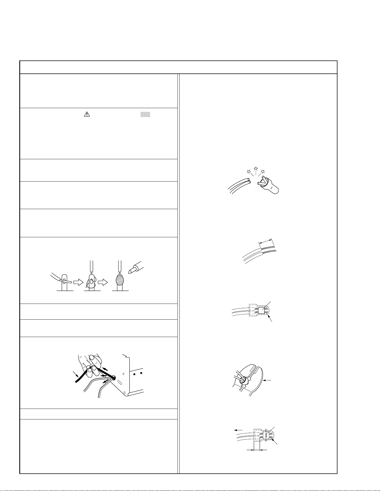
12. Crimp type wire connector
In such cases as when replacing the power transformer in sets
where the connections between the power cord and power
transformer primary lead wires are performed using crimp type
connectors, if replacing the connectors is unavoidable, in order to prevent safety hazards, perform carefully and precisely
according to the following steps.
1) Connector part number : E03830-001
2) Required tool : Connector crimping tool of the proper type
which will not damage insulated parts.
3) Replacement procedure
(1) Remove the old connector by cutting the wires at a point
close to the connector.
Important : Do not reuse a connector (discard it).
Fig.3
(2) Strip about 15 mm of the insulation from the ends of
the wires. If the wires are stranded, twist the strands to
avoid frayed conductors.
15 mm
Fig.1
7. Observe that wires do not contact heat producing parts
(heatsinks, oxide metal film resistors, fusible resistors, etc.)
8. Check that replaced wires do not contact sharp edged or
pointed parts.
9. When a power cord has been replaced, check that 10-15 kg of
force in any direction will not loosen it.
Power cord
Fig.2
10. Also check areas surrounding repaired locations.
11. Products using cathode ray tubes (CRTs)
In regard to such products, the cathode ray tubes themselves,
the high voltage circuits, and related circuits are specified for
compliance with recognized codes pertaining to X-ray emission.
Consequently, when servicing these products, replace the cathode ray tubes and other parts with only the specified parts.
Under no circumstances attempt to modify these circuits.
Unauthorized modification can increase the high voltage value
and cause X-ray emission from the cathode ray tube.
Fig.4
(3) Align the lengths of the wires to be connected. Insert
the wires fully into the connector.
Metal sleeve
Connector
Fig.5
(4) As shown in Fig.6, use the crimping tool to crimp the
metal sleeve at the center position. Be sure to crimp fully
to the complete closure of the tool.
1.25
2.0
5.5
Fig.6
(5) Check the four points noted in Fig.7.
Not easily pulled free
Wire insulation recessed
more than 4 mm
Fig.7
Crimping tool
Crimped at approx. center
of metal sleeve
Conductors extended
1
S40888-01
Page 5
v
d'
d
Chassis
Power cord,
primary wire
Safety Check after Servicing
Examine the area surrounding the repaired location for damage or deterioration. Observe that screws, parts and wires have been
returned to original positions, Afterwards, perform the following tests and confirm the specified values in order to verify compliance with safety standards.
1. Insulation resistance test
Confirm the specified insulation resistance or greater between power cord plug prongs and
externally exposed parts of the set (RF terminals, antenna terminals, video and audio input
and output terminals, microphone jacks, earphone jacks, etc.). See table 1 below.
2. Dielectric strength test
Confirm specified dielectric strength or greater between power cord plug prongs and exposed
accessible parts of the set (RF terminals, antenna terminals, video and audio input and output
terminals, microphone jacks, earphone jacks, etc.). See table 1 below.
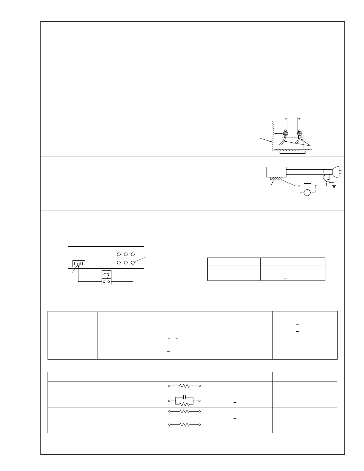
3. Clearance distance
When replacing primary circuit components, confirm specified clearance distance (d), (d’) between soldered terminals, and between terminals and surrounding metallic parts. See table 1
below.
Fig. 8
4. Leakage current test
Confirm specified or lower leakage current between earth ground/power cord plug prongs
and externally exposed accessible parts (RF terminals, antenna terminals, video and audio
input and output terminals, microphone jacks, earphone jacks, etc.).
Measuring Method : (Power ON)
Insert load Z between earth ground/power cord plug prongs and externally exposed accessible parts. Use an AC voltmeter to measure across both terminals of load Z. See figure 9 and
following table 2.
Externally
exposed
accessible part
Z
V
Fig. 9
ab
c
5. Grounding (Class 1 model only)
Confirm specified or lower grounding impedance between earth pin in AC inlet and externally exposed accessible parts (Video in,
Video out, Audio in, Audio out or Fixing screw etc.).
Measuring Method:
Connect milli ohm meter between earth pin in AC inlet and exposed accessible parts. See figure 10 and grounding specifications.
AC inlet
Earth pin
AC Line Voltage
100 V
100 to 240 V
110 to 130 V
110 to 130 V
200 to 240 V
Exposed accessible part
Milli ohm meter
Fig. 10
Region
Japan
USA & Canada
Europe & Australia R 10 MΩ/500 V DC
Region Load Z
Insulation Resistance (R)
≤
R 1 MΩ/500 V DC
≥≥
1 MΩ R 12 MΩ/500 V DC
≤
Table 1 Specifications for each region
Grounding Specifications
Region
USA & Canada
Europe & Australia
Dielectric Strength
AC 1 kV 1 minute
AC 1.5 kV 1 miute
AC 1 kV 1 minute
AC 3 kV 1 minute
AC 1.5 kV 1 minute
(Class 2)
(Class 1)
Grounding Impedance (Z)
≤
Z 0.1 ohm
≤
Z 0.5 ohm
Clearance Distance (d), (d')
≤
d, d' 3 mm
≤
d, d' 4 mm
≤
d, d' 3.2 mm
≤
d 4 mm
≤
d' 8 mm (Power cord)
≤
d' 6 mm (Primary wire)
a, b, cLeakage Current (i)AC Line Voltage
100 V
110 to 130 V
110 to 130 V
220 to 240 V
Note: These tables are unofficial and for reference only. Be sure to confirm the precise values for your particular country and locality.
Japan
USA & Canada
Europe & Australia
Table 2 Leakage current specifications for each region
1 kΩ
0.15 µF
1.5 kΩ
2 kΩ
50 kΩ
2
≤
i 1 mA rms Exposed accessible parts
≤
i 0.5 mA rms
≤
i 0.7 mA peak
≤
i 2 mA dc
≤
i 0.7 mA peak
≤
i 2 mA dc
Exposed accessible parts
Antenna earth terminals
Other terminals
S40888-01
Page 6
IMPORTANT WARNING
CAUTION:
DVD PLA YER IS A CLASS 1 LASER PRODUCT. HOWEVER THIS PLAYER USES A VISIBLE LASER
BEAM WHICH COULD CAUSE HAZARDOUS RADIATION EXPOSURE IF DIRECTED. BE SURE TO
OPERATE THE PLAYER CORRECTLY AS INSTRUCTED.
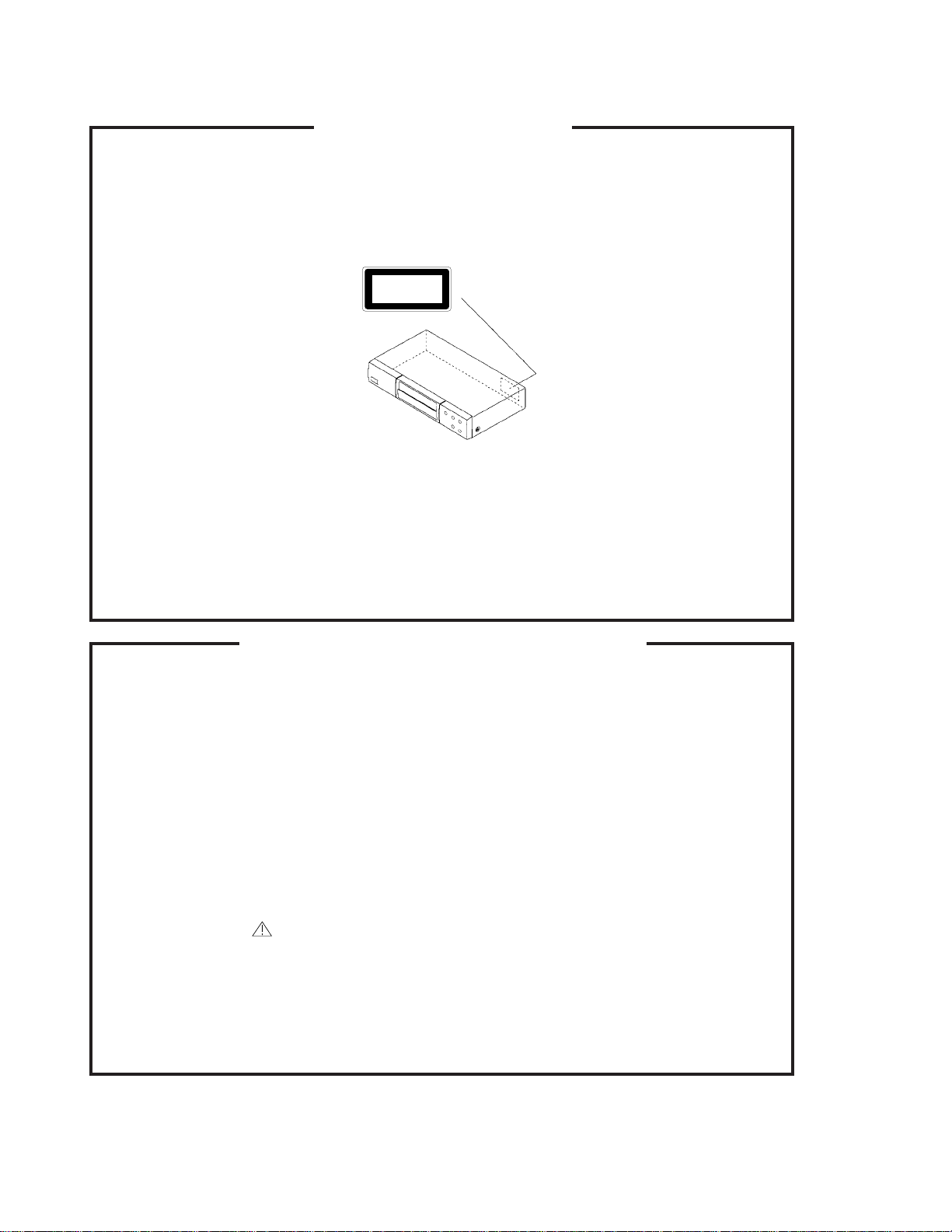
THE FOLLOWING CAUTION LABEL IS LOCATED ON THE REAR PANEL OF THE PLAYER.
CLASS 1
(Printed on the Rear Panel)
WHEN THIS PLAYER IS PLUGGED TO THE WALL OUTLET, DO NOT PLACE YOUR EYES CLOSE
TO THE OPENING OF THE DISC TRAY AND OTHER OPENINGS TO LOOK INTO THE INSIDE OF
THIS PLAYER.
USE OF CONTROLS OR ADJUSTMENTS OR PERFORMANCE OF PROCEDURES OTHER THAN
THOSE SPECIFIED HEREIN MAY RESULT IN HAZARDOUS RADIATION EXPOSURE.
DO NOT OPEN COVERS AND DO NOT REPAIR YOURSELF. REFER SERVICING TO QUALIFIED
PERSONNEL.
SERVICING NOTICES ON CHECKING
1. KEEP THE NOTICES 3. PUT PARTS AND WIRES IN THE
As for the places which need special attentions,
they are indicated with the labels or seals on the
cabinet, chassis and parts. Make sure to keep the
indications and notices in the operation manual.
2. USE THE DESIGNATED PARTS
The parts in this equipment have the specific
characters of incombustibility and withstand
voltage for safety. Therefore, the part which is
replaced should be used the part which has
the same character.
Especially as to the important parts for safety
which is indicated in the circuit diagram or the
table of parts as a mark, the designated
parts must be used.
LASER PRODUCT
ORIGINAL POSITION AFTER
ASSEMBLING OR WIRING
There are parts which use the insulation
material such as a tube or tape for safety, or
which are assembled in the condition that
these do not contact with the printed board.
The inside wiring is designed not to get closer
to the pyrogenic parts and high voltage parts.
Therefore, put these parts in the original
positions.
PERFORM A SAFETY CHECK AFTER
4.
SERVICING
Confirm that the screws, parts and wiring which
were removed in order to service are put in the
original positions, or whether there are the
portions which are deteriorated around the
serviced places serviced or not. Check the
insulation between the antenna terminal or
external metal and the AC cord plug blades.
And be sure the safety of that.
Page 7
DISASSEMBLY INSTRUCTIONS
1.
REMOVAL OF MECHANICAL PARTS
AND P.C. BOARDS
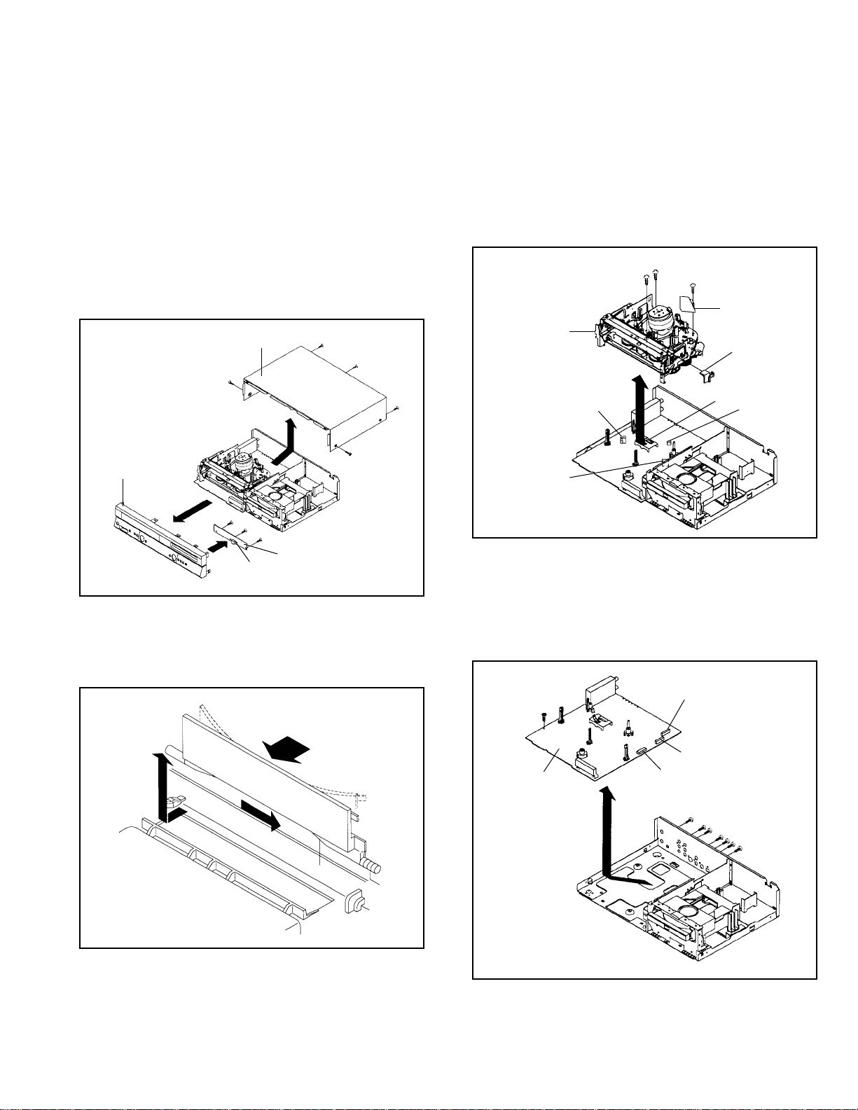
1-1:
TOP CABINET AND FRONT CABINET
(Refer to Fig. 2-1)
1.
Remove the 5 screws 1.
2.
Remove the Top Cabinet in the direction of arrow (A).
3.
Disconnect the following connector: (CP651).
4.
Unlock the 7 supports 2.
5.
Remove the Front Cabinet in the direction of arrow (B).
6.
Remove the 3 screws 3.
7.
Remove the Operation PCB in the direction of arrow (C).
Top Cabinet
1
(A)
Front Cabinet
(B)
2
2
2
2
3
3
2
2
3
CP651
2
1-2: FLAP (Refer to Fig. 1-2)
1.2.Open Flap to 90˚ and flex in direction of arrow (A), at the
same time slide in direction of arrow (B).
Then lift in direction of arrow (C).
1
1
1
1
Operation PCB
Fig. 1-1
1-3: VCR DECK (Refer to Fig. 1-3)
1.
Unlock the 2 supports 1 and remove the Top Holder.
2.
Remove the 3 screws 2.
3.
Disconnect the following connectors: (CP101, CP102,
CP103 and CP3001).
4.
Remove the AC Head Cover and VCR Deck in the
direction of arrow.
1
1
VCR Deck
CP103
CP3001
1
AC Head Cover
Top Holder
1
1
CP101
CP102
1-4: VCR MT PCB (Refer to Fig. 1-4)
1.
Remove the screw 1.
2.
Remove the 7 screws 2.
3.
Disconnect the following connectors: (CP1701,
CP8001 and CP8002).
4.
Remove the VCR MT PCB in the direction of arrow.
2
CP1701
Fig. 1-3
(C)
(B)
(A)
Flap
Fig. 1-2
VCR MT PCB
CP8002
CP8001
1
2
2
2
2
2
2
Fig. 1-4
1-1
Page 8
DISASSEMBLY INSTRUCTIONS
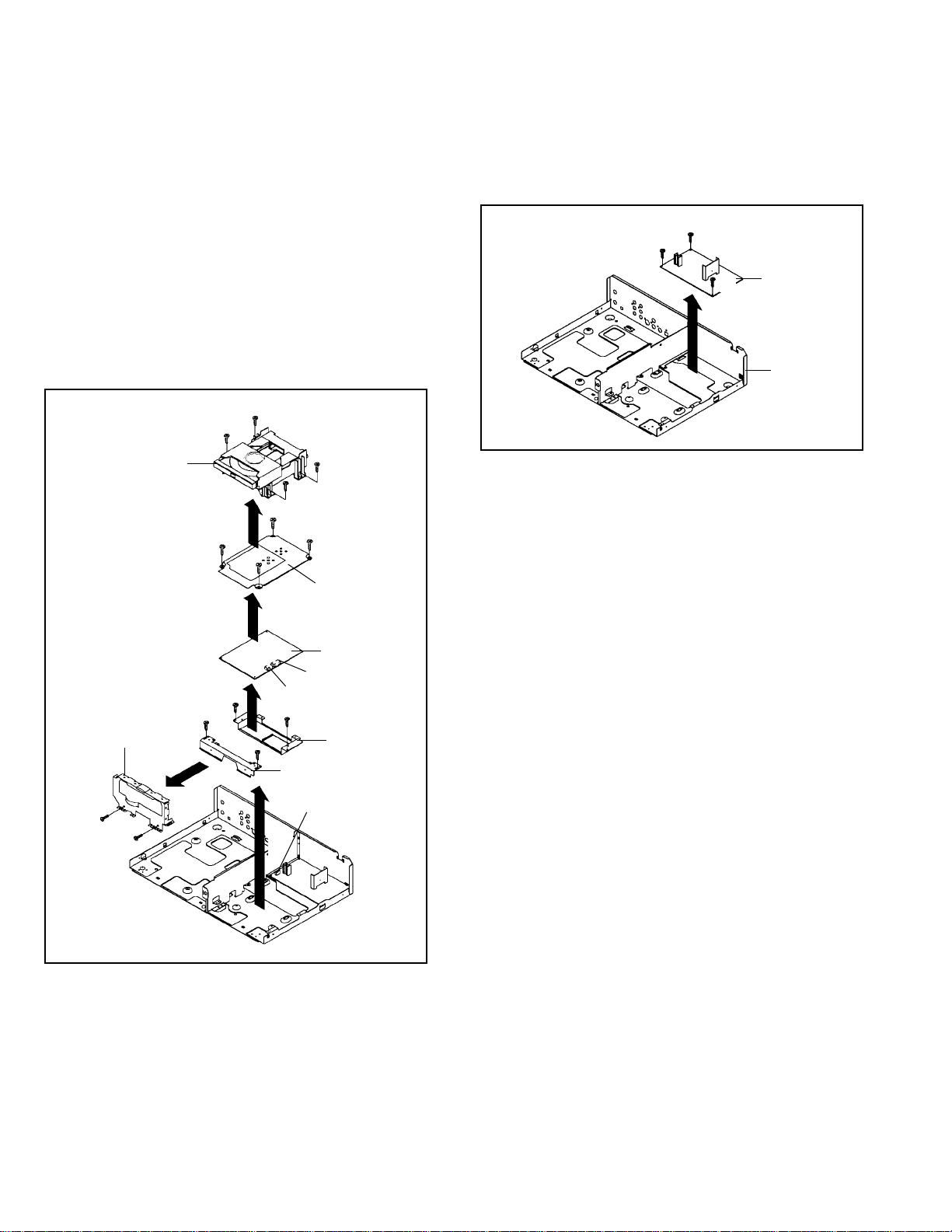
1-5: DECK CD AND MPEG MT PCB (Refer to Fig. 1-5)
1.
Disconnect the following connector: (CP503).
2.
Remove the 2 screws 1.
3.
Remove the 2 screws 2.
4.
Remove the Deck Angle 1/2 in the direction of arrow (A).
5.
Remove the 2 screws 3.
6.
Remove the Front Shield in the direction of arrow (B).
7.
Disconnect the following connectors: (CP4001 and
CP4002).
8.
Remove the 4 screws 4.
9.
Remove the Deck CD in the direction of arrow (C).
10.
Remove the 4 screws 5.
11.
Remove the MPEG Shield in the direction of arrow (D).
12.
Remove the MPEG MT PCB in the direction of arrow (E).
4
4
Deck CD
(C)
5
5
4
4
5
5
MPEG Shield
1-6: POWER PCB (Refer to Fig. 1-6)
1.2.Remove the 3 screws 1.
Remove the Power PCB in the direction of arrow.
1
1
1
Power PCB
Bottom Plate
Fig. 1-6
(D)
MPEG MT PCB
CP4001
CP4002
2
1
(B)
3
3
(E)
1
Deck Angle 1
(A)
2
Deck Angle 2Front Shield
CP503
Fig. 1-5
1-2
Page 9
DISASSEMBLY INSTRUCTIONS
2. REMOVAL OF VCR DECK PARTS
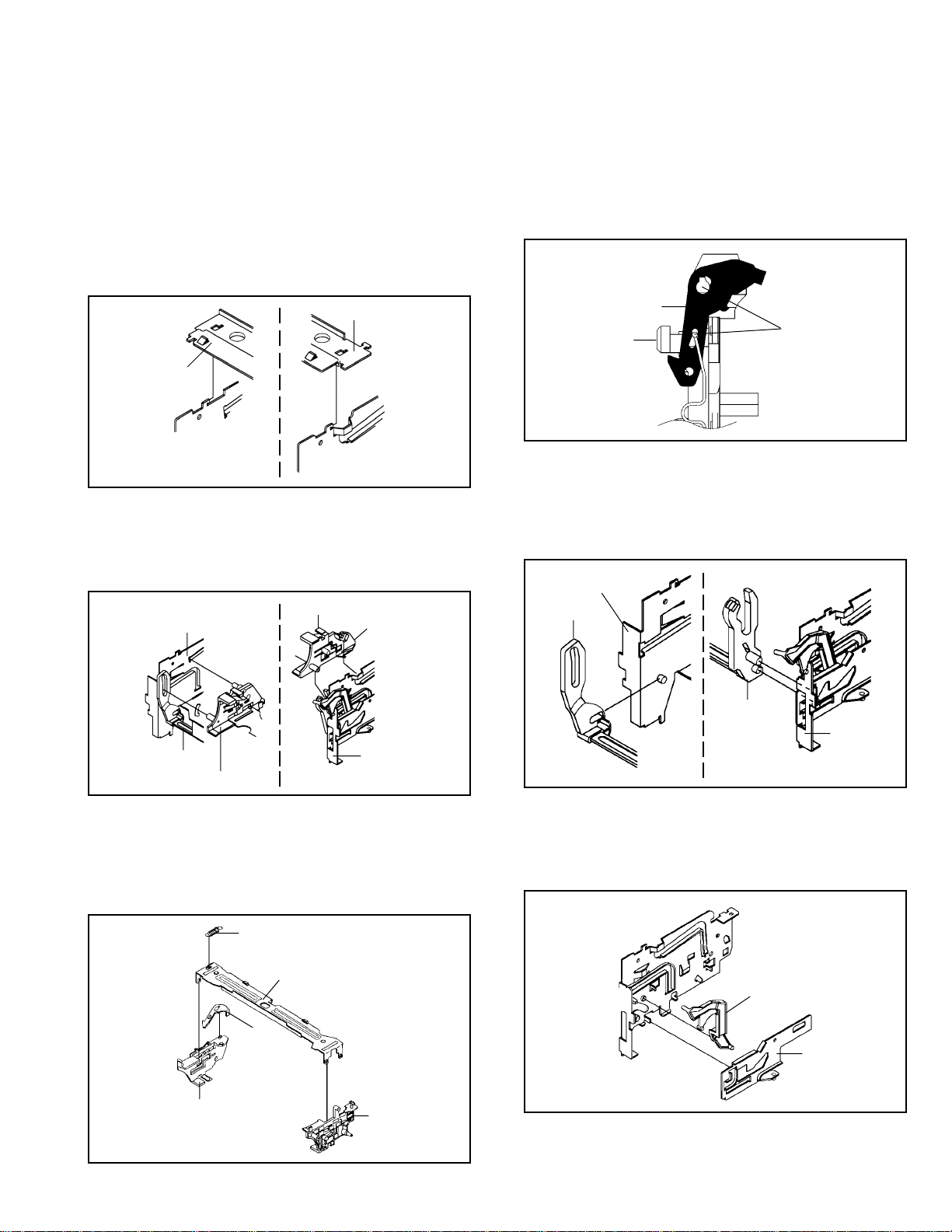
2-1: TOP BRACKET (Refer to Fig. 2-1)
Extend the 2 supports 1.
1.
Slide the 2 supports 2 and remove the Top Bracket.
2.
NOTE
After the installation of the Top Bracket, bend the support
1.
1 so that the Top Bracket is fixed.
Top Bracket
1
Top Bracket
2
Main Chassis
2
Main Chassis
2-2: CASSETTE HOLDER ASS'Y (Refer to Fig. 2-2)
1.
Move the Cassette Holder Ass'y to the front side.
2.
Push the Locker R to remove the Cassette Side R.
3.
Remove the Cassette Side L.
Cassette Side R
Main Chassis
1
Locker R
Fig. 2-1
NOTE
In case of the Locker R installation, check if the two
1.
positions of Fig. 2-3-B are correctly locked.
When you install the Cassette Side R, be sure to move
2.
the Locker R after installing.
Locker R
Check if these
Cassette Side R
positions are locked.
2-4: LINK UNIT (Refer to Fig. 2-4)
1.
Set the Link Unit to the Eject position.
2.
Unlock the support 1.
3.
Remove the (A) side of the Link Unit first, then remove
the (B) side.
Main Chassis
Link Unit
Fig. 2-3-B
Link Unit
Cassette Side L
Main Chassis
2-3: CASSETTE SIDE L/R (Refer to Fig. 2-3-A)
1.
Remove the Locker Spring.
2.
Unlock the 4 supports 1 and then remove the Cassette
Side L/R.
3.
Unlock the support 2 and then remove the Locker R.
Locker Spring
1
1
2
Cassette Side R
Cassette Holder
Locker R
1
1
Cassette Side L
Fig. 2-2
(A)
(B)
Link Unit
Main Chassis
2-5: LINK LEVER/FLAP LEVER (Refer to Fig. 2-5)
1.
Extend the support 1.
2.
Remove the Link Lever.
3.
Remove the Flap Lever.
1
Flap Lever
Link Lever
Fig. 2-4
Fig. 2-5
Fig. 2-3-A
1-3
Page 10
DISASSEMBLY INSTRUCTIONS
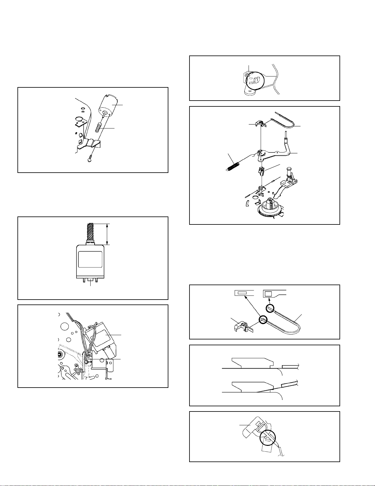
2-6: LOADING MOTOR/WORM (Refer to Fig. 2-6-A)
1.
Remove the screw 1.
2.
Remove the Loading Motor.
3.
Remove the Worm.
Loading Motor
Worm
Main Chassis
• Screw Torque: 3 ± 0.5kgf•cm
1
Fig. 2-6-A
NOTE
1.2.In case of the Worm installation, check if the value of the
Fig. 2-6-B is correct.
In case of the Loading Motor installation, hook the wire
on the Cassette Opener as shown Fig. 2-6-C.
19.2 ± 0.1mm
Safety surface for pressing
of the insert.
Fig. 2-6-B
T ension Arm Ass’y
Fig. 2-7-A
1
Tension Connect
Tension Spring
2
4
1
3
Tension Holder
Tension Band
T ension Arm Ass’y
Fig. 2-7-B
NOTE
1.
In case of the Tension Band installation, note the direction of the installation. (Refer to Fig. 2-7-C)
2.
In case of the Tension Band installation, install correctly
as Fig. 2-7-D.
3.
In case of the Tension Connect installation, install as the
circled section of Fig. 2-7-E.
Loading Motor
Cassette Opener
Fig. 2-6-C
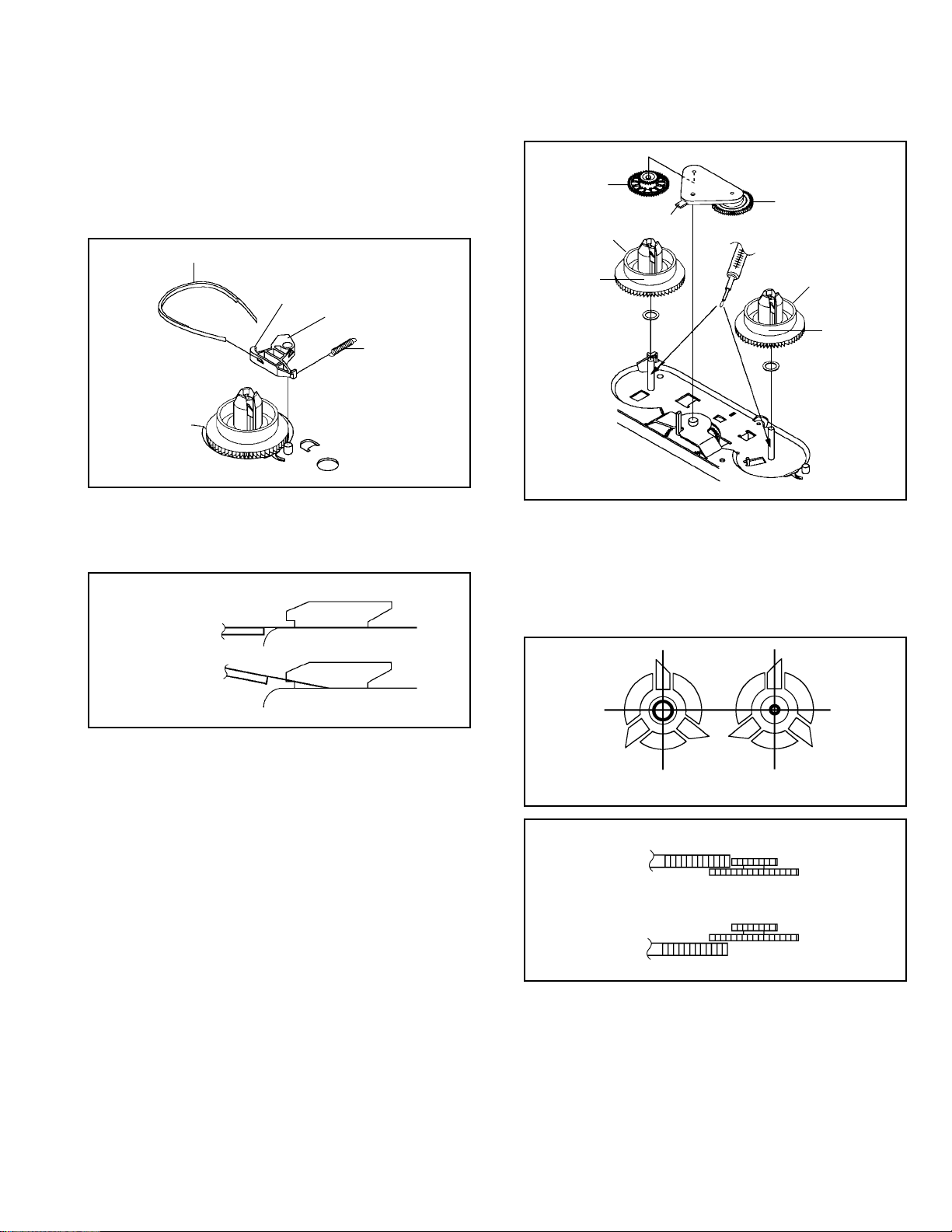
2-7: TENSION ASS’Y (Refer to Fig. 2-7-B)
1.
Turn the Pinch Roller Cam clockwise so that the Tension
Holder hook is set to the position of Fig. 2-7-A to move
the Tension Arm Ass’y.
2.
Remove the Tension Spring.
3.
Unlock the 2 supports 1 and remove the Tension Band.
4.
Unlock the support 2 and remove the Tension Arm Ass’y.
5.
Unlock the support 3 and remove the Tension Connect.
6.
Float the hook 4 and turn it clockwise then remove the
Tension Holder.
1-4
Tension Connect
[OK]
[NG]
Tension Connect
Tension Connect
Tension Connect
Main Chassis
Tension Band
Fig. 2-7-C
Tension Band
Tension Band
Fig. 2-7-D
Fig. 2-7-E
Page 11
DISASSEMBLY INSTRUCTIONS
2-8: T BRAKE ARM/T BRAKE BAND (Refer to Fig. 2-8-A)
Remove the T Brake Spring.
1.
Turn the T Brake Arm clockwise and bend the hook
2.
section to remove it.
Unlock the 2 supports 1 and remove the T Brake Band.
3.
T Brake Band
Hook section
1
1
T Brake Arm
T Brake Spring
Idler Gear
(A)
Idler Arm Ass’y
(B)
S Reel
T Reel
1
(A)
1
Fig. 2-8-A
NOTE
1. In case of the T Brake Band installation, install correctly
as Fig. 2-8-B.
[OK]
T Brake Band
[NG]
T Brake Band
T Brake Arm
T Brake Arm
Fig. 2-8-B
2-9: S REEL/T REEL/IDLER ARM ASS’Y/IDLER GEAR
(Refer to Fig. 2-9-A)
1.
Remove the S Reel and T Reel.
2.
Remove the 2 Polyslider Washers 1.
3.
Remove the Idler Arm Ass’y and Idler Gear.
NOTE
1.
Take care not to damage the gears of the S Reel and T
Reel.
2.
The Polyslider Washer may be remained on the back of
the reel.
3.
Take care not to damage the shaft.
4.
Do not touch the section “A” of S Reel and T Reel. (Use
gloves.) (Refer to Fig. 2-9-A) Do not adhere the stains
on it.
5.
When you install the reel, clean the shaft and grease it
(FG-84M). (If you do not grease, noise may be heard in
FF/REW mode.)
6.
After installing the reel, adjust the height of the reel.
(Refer to MECHANICAL ADJUSTMENT)
Fig. 2-9-A
NOTE
1.2.In case of the S Reel and T Reel installation, check if the
correct parts are installed. (Refer to Fig. 2-9-B)
In case of the Idler Arm Ass’y installation, install correctly
as Fig. 2-9-C. And also set it so that the section “B” of
Fig. 2-9-A is placed under the Main Chassis tab.
Big Hole
(S Reel)
Small Hole
(T Reel)
Fig. 2-9-B
[OK]
Clutch Gear
Idler Arm Ass’y
[NG]
Idler Arm Ass’y
Clutch Gear
Fig. 2-9-C
1-5
Page 12
DISASSEMBLY INSTRUCTIONS
2-10: CASSETTE OPENER/PINCH ROLLER BLOCK/P5
ARM ASS’Y (Refer to Fig. 2-10-A)
1.2.Unlock the support 1 and remove the Cassette Opener.
Remove the Pinch Roller Block and P5 Arm Ass’y.
1
Cassette Opener
Pinch Roller Block
P5 Arm Ass’y
Main Chassis
Fig. 2-10-A
NOTE
1.2.Do not touch the Pinch Roller. (Use gloves.)
In case of the Pinch Roller Block and the Pinch Roller
Cam installation, install correctly as Fig. 2-10-B.
Pinch Roller Block
P5 Arm Ass’y
Can be seen the hole of the
Main Cam.
Can be seen the hole of
the Pinch Roller Cam.
Fig. 2-10-B
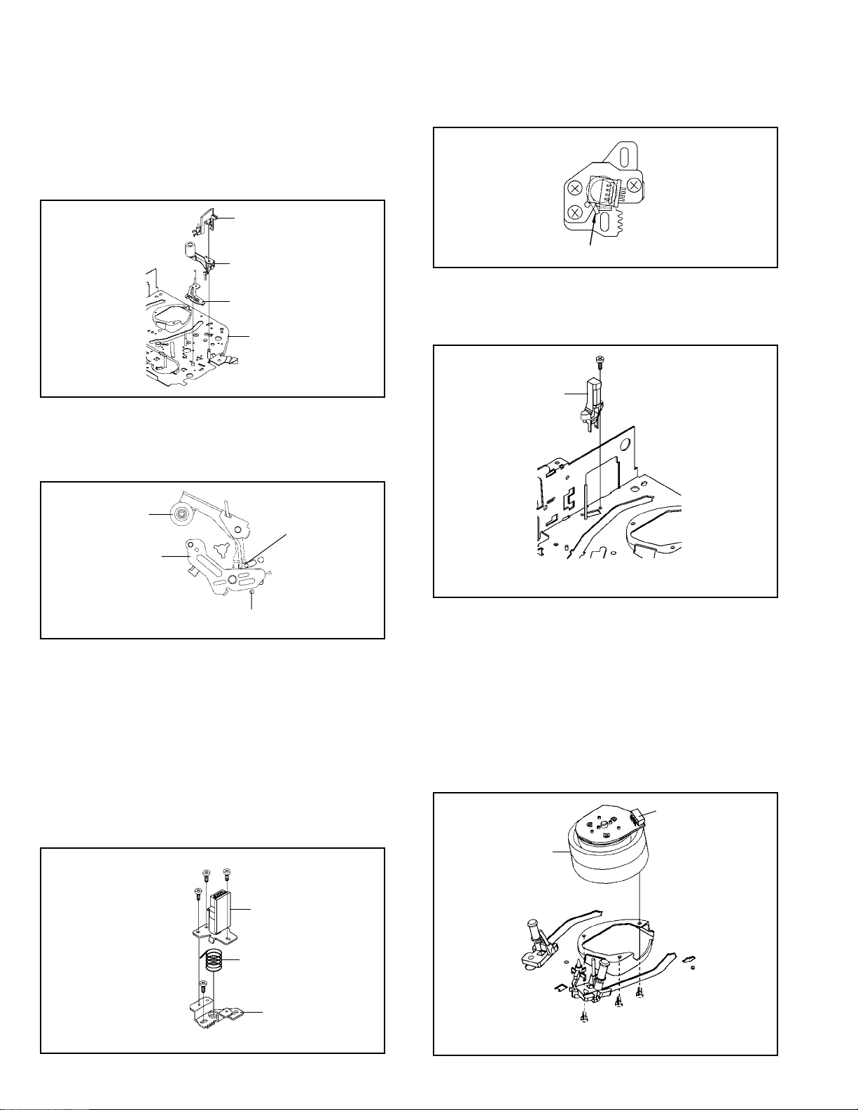
2-11: A/C HEAD (Refer to Fig. 2-11-A)
1.
Remove the screw 1.
2.
Remove the A/C Head Base.
3.
Remove the 3 screws 2.
4.
Remove the A/C Head and A/C Head Spring.
NOTE
1.
Do not touch the A/C Head. (Use gloves.)
2.
When you install the A/C Head Spring, install as shown in
Fig. 2-11-B.
3.
When you install the A/C Head, tighten the screw (1) first,
then tighten the screw (2), finally tighten the screw (3).
(3)
(1)
2
2
(2)
2
A/C Head
Spring Position
Fig. 2-11-B
2-12: FE HEAD (RECORDER ONLY) (Refer to Fig. 2-12)
1.2.Remove the screw 1.
Remove the FE Head.
1
FE Head
• Screw Torque: 5 ± 0.5kgf•cm
• The FE Head is not installed on the Video Cassette Player.
Fig. 2-12
2-13: AHC ASS’Y/CYLINDER UNIT ASS’Y
(Refer to Fig. 2-13)
1.
Disconnect the following connector:
(CD2001)
2.
Remove the 3 screws 1.
3.
Remove the Cylinder Unit Ass’y.
NOTE
1. When you install the Cylinder Unit Ass’y, tighten the
screws from (1) to (3) in order while pulling the Ass’y
toward the left front direction.
CD2001
Cylinder Unit Ass’y
• Screw Torque: 5 ± 0.5kgf•cm (Screw 1)
1-6
A/C Head Spring
1
A/C Head Base
Fig. 2-11-A
• Screw Torque: 3 ± 0.5kgf•cm
(2)
(1)
1
(3)
1
1
Fig. 2-13
Page 13
DISASSEMBLY INSTRUCTIONS
2-14: CAPSTAN DD UNIT (Refer to Fig. 2-14-A)
1.
Remove the Capstan Belt.
2.
Remove the 3 screws 1.
3.
Remove the Capstan DD Unit.
Capstan Belt
Capstan DD Unit
1
1
1
• Screw Torque: 4 ± 0.5kgf•cm
Fig. 2-14-A
NOTE
1. In case of the Capstan DD Unit installation, apply the
silicon bond (TSE3843-W) on the position Fig. 2-14-B
correctly. (If no silicon bond applied, abnormal noise will
be heard on the deck operation.)
(Refer to Fig. 2-14-B, C)
Applied position of
silicon bond
2-15: MAIN CAM/PINCH ROLLER CAM/JOINT GEAR
(Refer to Fig. 2-15-A)
1.2.Remove the E-Ring 1, then remove the Main Cam.
Remove the E-Ring 2, then remove the Pinch Roller
Cam and Joint Gear.
1
Main Cam
2
Pinch Roller Cam
Joint Gear
Fig. 2-15-A
NOTE
1. In case of the Pinch Roller Cam and Main Cam installation, install them as the circled section of Fig. 2-15-B so
that the each markers are met. (Refer to Fig. 2-15-B)
And also can be seen the Main Chassis hole through the
Main Cam maker hole.
Pinch Roller Cam
Marker
Main Cam
Be careful not to apply the silicon
bond to the Pinch Roller.
Capstan DD Unit
Silicon Bond
Main Chassis
Fig. 2-14-B
Fig. 2-14-C
Fig. 2-15-B
2-16: LOADING GEAR S/T UNIT (Refer to Fig. 2-16-A)
1.2.Remove the E-Ring 1 and remove the Main Loading
Gear.
Remove the Main Rod, Tension Lever, Loading Arm S
Unit and Loading Arm T Unit.
1
Main Rod
Tension Lever
Main Loading Gear
Loading Arm T Unit
Loading Arm S Unit
Fig. 2-16-A
1-7
Page 14
DISASSEMBLY INSTRUCTIONS
NOTE
1. When you install the Loading Arm S Unit, Loading Arm T
Unit and Main Loading Gear, align each marker. (Refer
to Fig. 2-16-B)
Marker
Main Loading Gear
Marker
Loading Arm T Unit Loading Arm S Unit
Fig. 2-16-B
2-17: CLUTCH ASS’Y/RING SPRING/CLUTCH LEVER/
CLUTCH GEAR (Refer to Fig. 2-17-A)
1.
Remove the Polyslider Washer 1.
2.
Remove the Clutch Ass’y and Ring Spring.
3.
Remove the Clutch Lever.
4.
Remove the Coupling Gear, Coupling Spring and Clutch
Gear.
1
Clutch Ass’y
Ring Spring
2-18: CASSETTE GUIDE POST/INCLINED BASE S/T
UNIT/P4 CAP (Refer to Fig. 2-18-A)
1.
Remove the P4 Cap.
2.
Unlock the support 1 and remove the Cassette Guide
Post.
3.
Remove the Inclined Base S Unit and Inclined Base T
Unit.
1
Inclined Base S
Unit Inclined Base T
Cassette Guide Post
Unit
P4 Cap
Fig. 2-18-A
NOTE
1.
Do not touch the roller of Guide Roller.
2.
In case of the P4 Cap installation, install it with parallel
for “A” and “B” of Fig. 2-18-B.
3.
In case of the Cassette Guide Post installation, install
correctly as the circled section of Fig. 2-18-C.
Coupling Gear
Coupling Spring
Clutch Gear
Clutch Lever
Fig. 2-17-A
NOTE
1. In case of the Clutch Ass’y installation, install it with
inserting the spring of the Clutch Ass’y into the dent of the
Coupling Gear. (Refer to Fig. 2-17-B)
Clutch Ass’y
Coupling Gear
Fig. 2-17-B
“A”“B”
P4 Cap
[OK]
Cassette Guide Post
[NG]
Cassette Guide Post
Cassette Opener
Fig. 2-18-B
Fig. 2-18-C
1-8
Page 15
DISASSEMBLY INSTRUCTIONS
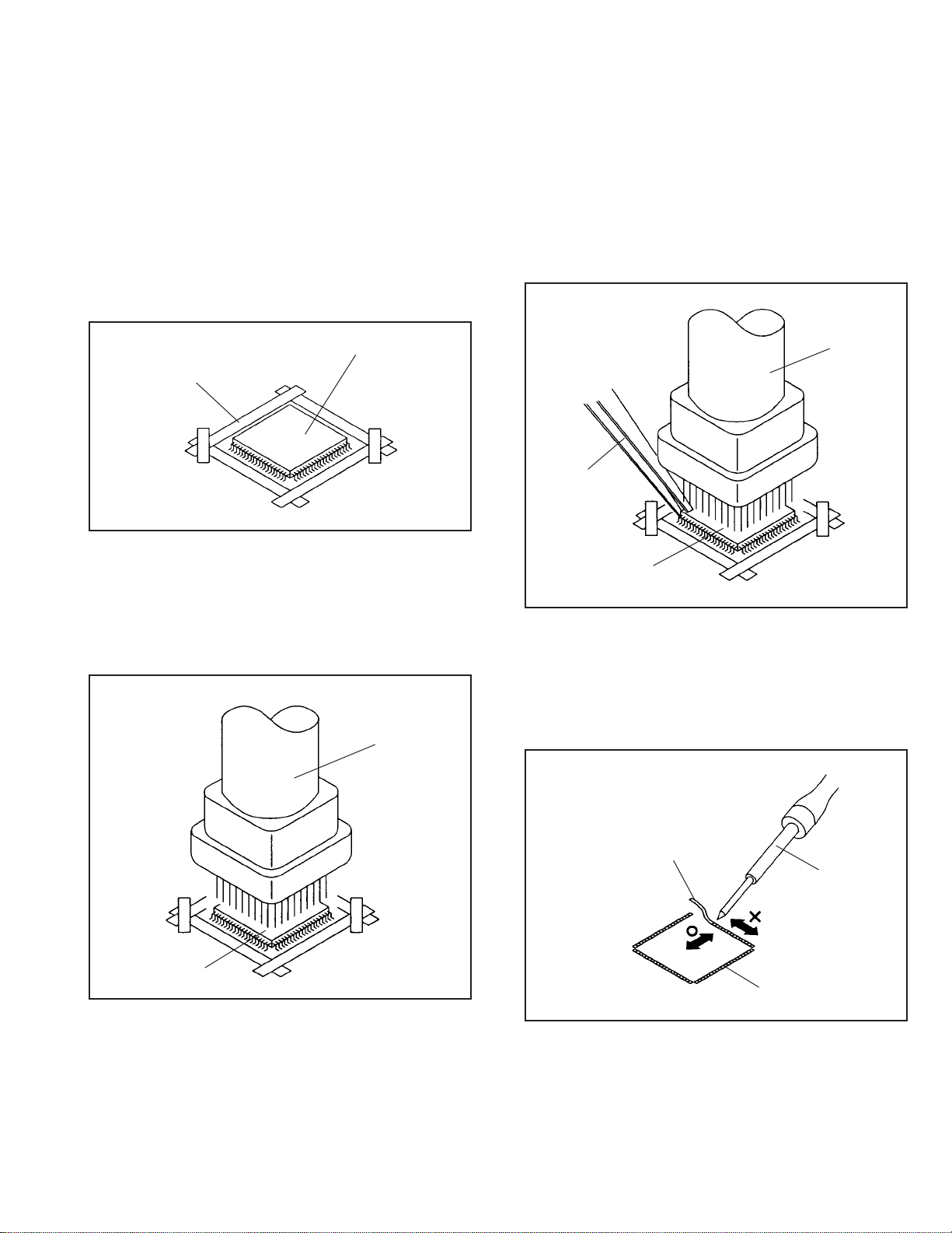
3. REMOVAL AND INSTALLATION OF FLAT PACKAGE IC
REMOVAL
1. Put the Masking Tape (cotton tape) around the Flat
Package IC to protect other parts from any damage.
(Refer to Fig. 4-1.)
NOTE
Masking is carried out on all the parts located within
10 mm distance from IC leads.
Masking T ape
(Cotton Tape)
2. Heat the IC leads using a blower type IC desoldering
machine. (Refer to Fig. 4-2.)
NOTE
Do not add the rotating and the back and forth directions force on the IC, until IC can move back and forth
easily after desoldering the IC leads completely.
IC
Fig. 4-1
Blower type IC
desoldering machine
3. When IC starts moving back and forth easily after
desoldering completely, pickup the corner of the IC using
a tweezers and remove the IC by moving with the IC
desoldering machine. (Refer to Fig. 4-3.)
NOTE
Some ICs on the PCB are affixed with glue, so be
careful not to break or damage the foil of each IC
leads or solder lands under the IC when removing it.
Blower type IC
desoldering machine
Tweezers
IC
4.5.Peel off the Masking Tape.
Absorb the solder left on the pattern using the Braided
Shield Wire. (Refer to Fig. 4-4.)
NOTE
Do not move the Braided Shield Wire in the vertical
direction towards the IC pattern.
Fig. 43
Braided Shield Wire
Soldering Iron
IC
Fig. 4-2
IC pattern
Fig. 4-4
1-9
Page 16
DISASSEMBLY INSTRUCTIONS
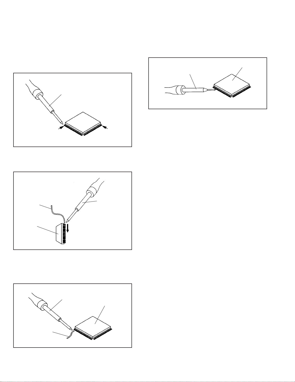
INSTALLATION
1. Take care of the polarity of new IC and then install the
new IC fitting on the printed circuit pattern. Then solder
each lead on the diagonal positions of IC temporarily.
(Refer to Fig. 4-5.)
Soldering Iron
Solder temporarily Solder temporarily
Fig. 4-5
2. Supply the solder from the upper position of IC leads
sliding to the lower position of the IC leads.
(Refer to Fig. 4-6.)
4. When bridge-soldering between terminals and/or the
soldering amount are not enough, resolder using a Thintip Soldering Iron. (Refer to Fig. 4-8.)
IC
Thin-tip Soldering Iron
Fig. 4-8
5. Finally, confirm the soldering status on four sides of the
IC using a magnifying glass.
Confirm that no abnormality is found on the soldering
position and installation position of the parts around the
IC. If some abnormality is found, correct by resoldering.
NOTE
When the IC leads are bent during soldering and/or
repairing, do not repair the bending of leads. If the
bending of leads are repaired, the pattern may be
damaged. So, be always sure to replace the IC in this
case.
Solder
IC
Supply soldering
from upper position
to lower position
Soldering Iron
Fig. 4-6
3. Absorb the solder left on the lead using the Braided
Shield Wire. (Refer to Fig. 4-7.)
NOTE
Do not absorb the solder to excess.
Soldering Iron
IC
Braided Shield Wire
1-10
Fig. 4-7
Page 17

A
A/C
ACC
AE
AFC
AFT
AFT DET
AGC
AMP
ANT
A.PB
APC
ASS’Y
AT
AUTO
A/V
B
BGP
BOT
BPF
BRAKE SOL
BUFF
B/W
C
C
CASE
CAP
CARR
CH
CLK
CLOCK (SY-SE)
COMB
CONV
CPM
CTL
CYL
CYL-M
CYL SENS
D
DATA (SY-CE)
dB
DC
DD Unit
DEMOD
DET
DEV
E
E
EF
EMPH
ENC
ENV
EOT
EQ
EXT
F
F
FBC
FE
FF
FG
FL SW
FM
FSC
FWD
G
GEN
GND
H
H.P.F
KEY TO ABBREVIATIONS
:
Audio/Control
:
Automatic Color Control
:
Audio Erase
:
Automatic Frequency Control
:
Automatic Fine Tuning
:
Automatic Fine Tuning Detect
:
Automatic Gain Control
:
Amplifier
:
Antenna
:
Audio Playback
:
Automatic Phase Control
:
Assembly
:
All Time
:
Automatic
:
Audio/Video
:
Burst Gate Pulse
:
Beginning of Tape
:
Bandpass Filter
:
Brake Solenoid
:
Buffer
:
Black and White
:
Capacitance, Collector
:
Cassette
:
Capstan
:
Carrier
:
Channel
:
Clock
:
Clock (Syscon to Servo)
:
Combination, Comb Filter
:
Converter
:
Capstan Motor
:
Control
:
Cylinder
:
Cylinder-Motor
:
Cylinder-Sensor
:
Data (Syscon to Servo)
:
Decibel
:
Direct Current
:
Direct Drive Motor Unit
:
Demodulator
:
Detector
:
Deviation
:
Emitter
:
Emitter Follower
:
Emphasis
:
Encoder
:
Envelope
:
End of Tape
:
Equalizer
:
External
:
Fuse
:
Feed Back Clamp
:
Full Erase
:
Fast Forward, Flipflop
:
Frequency Generator
:
Front Loading Switch
:
Frequency Modulation
:
Frequency Sub Carrier
:
Forward
:
Generator
:
Ground
:
High Pass Filter
H.SW
Hz
I
IC
IF
IND
INV
K
KIL
L
L
LED
LIMIT AMP
LM, LDM
LP
L.P.F
LUMI.
M
M
MAX
MINI
MIX
MM
MOD
MPX
MS SW
N
NC
NR
O
OSC
OPE
P
PB
PB CTL
PB-C
PB-Y
PCB
P. CON
PD
PG
P-P
R
R
REC
REC-C
REC-Y
REEL BRK
REEL S
REF
REG
REW
REV, RVS
RF
RMC
RY
S
S. CLK
S. COM
S. DATA
SEG
SEL
SENS
SER
SI
SIF
SO
SOL
SP
STB
SW
:
Head Switch
:
Hertz
:
Integrated Circuit
:
Intermediate Frequency
:
Indicator
:
Inverter
:
Killer
:
Left
:
Light Emitting Diode
:
Limiter Amplifier
:
Loading Motor
:
Long Play
:
Low Pass Filter
:
Luminance
:
Motor
:
Maximum
:
Minimum
:
Mixer, mixing
:
Monostable Multivibrator
:
Modulator, Modulation
:
Multiplexer, Multiplex
:
Mecha State Switch
:
Non Connection
:
Noise Reduction
:
Oscillator
:
Operation
:
Playback
:
Playback Control
:
Playback-Chrominance
:
Playback-Luminance
:
Printed Circuit Board
:
Power Control
:
Phase Detector
:
Pulse Generator
:
Peak-to Peak
:
Right
:
Recording
:
Recording-Chrominance
:
Recording-Luminance
:
Reel Brake
:
Reel Sensor
:
Reference
:
Regulated, Regulator
:
Rewind
:
Reverse
:
Radio Frequency
:
Remote Control
:
Relay
:
Serial Clock
:
Sensor Common
:
Serial Data
:
Segment
:
Select, Selector
:
Sensor
:
Search Mode
:
Serial Input
:
Sound Intermediate Frequency
:
Serial Output
:
Solenoid
:
Standard Play
:
Serial Strobe
:
Switch
1-11
Page 18

S
SYNC
SYNC SEP
T
TR
TRAC
TRICK PB
TP
U
UNREG
V
V
VCO
VIF
VP
V.PB
VR
V.REC
VSF
VSR
VSS
V-SYNC
VT
X
X’TAL
Y
Y/C
KEY TO ABBREVIATIONS
:
Synchronization
:
Sync Separator, Separation
:
Transistor
:
Tracking
:
Trick Playback
:
Test Point
:
Unregulated
:
Volt
:
Voltage Controlled Oscillator
:
Video Intermediate Frequency
:
Vertical Pulse, Voltage Display
:
Video Playback
:
Variable Resistor
:
Video Recording
:
Visual Search Fast Forward
:
Visual Search Rewind
:
Voltage Super Source
:
Vertical-Synchronization
:
Voltage Tuning
:
Crystal
:
Luminance/Chrominance
1-12
Page 19
SERVICE MODE LIST
This unit provided with the following SERVICE MODES so you can repair, examine and adjust easily.
To enter to the SERVICE MODE function, press and hold both buttons simultaneously on the main unit or on the main unit and on
the remote control for more than a standard time (second).
Set Key Operations
CH UP
CH UP STOP 2
CH UP PLAY 2
Set Key
REC 5 2
Set Key
FF 2
Standard Time
(seconds)
Standard Time
(seconds)
PLAY/REC total hours are displayed on the screen.
Refer to the “PREVENTIVE CHECKS AND SERVICE INTERVALS”
(CONFIRMATION OF HOURS USED).
Can be checked of the INITIAL DATA of MEMORY IC.
Refer to the “NOTE FOR THE REPLACING OF MEMORY IC”.
Adjust the SWITHCHING POINT automatically.
Refer to the “ELECTRICAL ADJUSTMENT” (SWITHCHING POINT).
Initialization of the factory on VCR.
NOTE: Do not use this for the normal servicing.
If you set a factory initialization, the memories are reset such as
the clock setting, the channel setting, and PLAY/REC total hours.
OperationsRemocon Key
Initialization of the factory on DVD.
NOTE: The function will only work without the setting of DVD disc at DVD
mode.
Do not use this for the normal servicing.
REC 6 2
STOP 1 3
STOP 7 3
Method Operations
Press the ATR button on the
remote control for more than
2 seconds during PLAY.
Make the short circuit
between the test point of
SERVICE and the GND.
Adjusting of the Tracking to the center position.
Refer to the “MECHANICAL ADJUSTMENT” (GUIDE ROLLER) and “ELECTRICAL
ADJUSTMENT” (SWITHCHING POINT).
The BOT, EOT, and the Reel Sensor do not work and the VCR deck can be operated
without a cassette tape.
Refer to the “PREPARATION FOR SERVICING”
DVD Write mode.
Refer to the “UP-DATE FOR THE FIRMWARE”.
NOTE: The function will only work at the DVD stop mode.
Do not use this for the normal servicing.
Check for the firmware version.
Refer to the “CHECK FOR THE FIRMWARE VERSION”.
NOTE: The function will only work at the DVD stop mode.
Do not use this for the normal servicing.
Releasing of PARENTAL LOCK.
Refer to the “PARENTAL CONTROL - RATING LEVEL”.
NOTE:
The function will only work without the setting of DVD disc at DVD
mode.
1-13
Page 20
WHEN REPLACING EEPROM (MEMORY) IC
If a service repair is undertaken where it has been required to change the MEMORY IC, the following steps should be taken to
ensure correct data settings while making reference to TABLE 1.
NOTE: No need setting for after INI 2D.
INI+0+1+2+3+4+5+6+7+8+9+A+B+C+D+E+F
00
0A A0 CA 10 64 64 4A 86 0B 2F 86 2F 0A 08 0A 0F
10 AF 97 95 8A 40 55 31 04 24 A5 9F 3A 00 10 BF 00
20
29 01 15 77 61 31 29 04 00 00 00 00 A2 B0 --- ---
Tabl e 1
1.
Connect the set to TV Monitor.
2.
Turn on the POWER.
3.
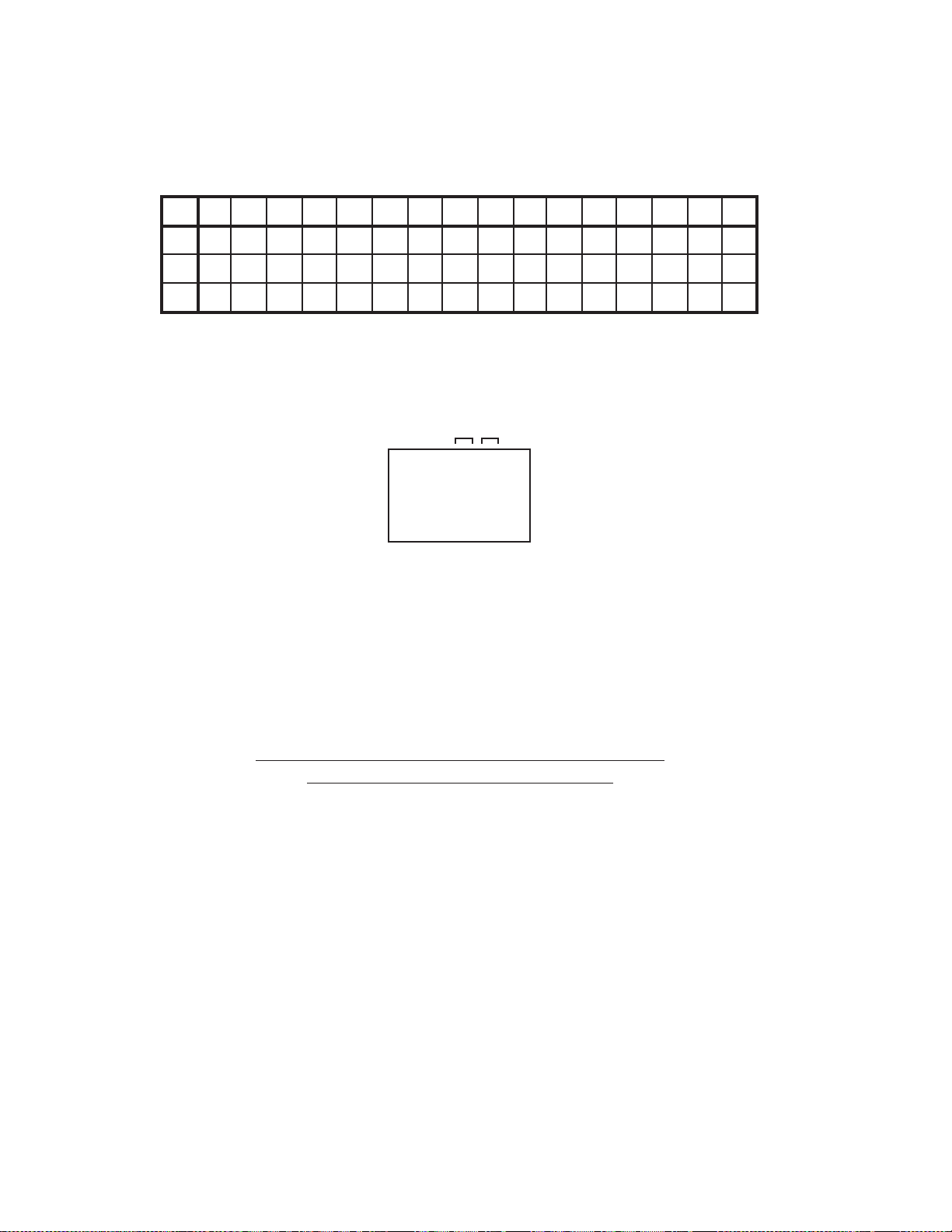
Press both CH UP button on the set and the FF button on the set for more than 2 seconds.
ADDRESS and DATA will appear on TV Monitor as Fig 1.
ADDRESS DATA
INIT 00 C2
Y/REC 0000
PLA
Fig. 1
ADDRESS is now selected and should “blink”. Using the SET + or - button on the remote, step through the ADDRESS until
4.
required ADDRESS to be changed is reached.
Press ENTER to select DATA. When DATA is selected, it will “blink”.
5.
Again, step through the DATA using SET + or - button until required DATA value has been selected.
6.
Pressing ENTER will take you back to ADDRESS for further selection if necessary.
7.
Repeat steps 4 to 7 until all data has been checked.
8.
When satisfied correct DATA has been entered, turn POWER off (return to STANDBY MODE) to finish DATA input.
9.
The unit will now have the correct DATA for the new MEMORY IC.
PARENTAL CONTROL - RATING LEVEL
4 DIGIT PASSWORD CANCELLATION
If the stored 4 digit password in the Rating Level menu needs to be cancelled, please follow the steps below.
Ensure the DVD Set is connected to the TV.
1.
Turn Unit ON.
2.
Confirm that no sisc on the disc tray.
3.
Press and hold the '7' key on the remote control unit.
4.
Simultaneously press and hold the 'STOP' key on the front panel.
5.
Hold both keys for more than 3 seconds.
6.
The On Screen Display message 'INITIALIZED' will appear.
7.
The 4 digit password has now been cleared.
8.
NB:
The above procedure will reset ALL of the player's settings to the default factory state.
1-14
Page 21
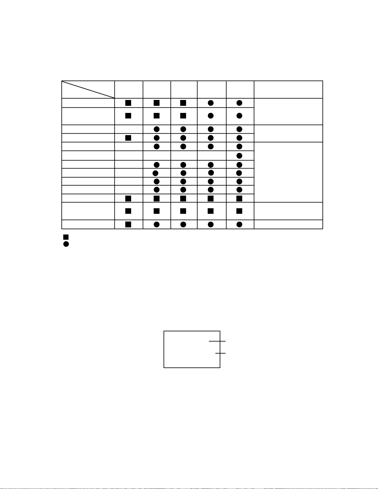
PREVENTIVE CHECKS AND SERVICE INTERVALS
The following standard table depends on environmental conditions and usage.
Parts replacing time does not mean the life span for individual parts.
Also, long term storage or misuse may cause transformation and aging of rubber parts.
The following list means standard hours, so the checking hours depends on the conditions.
Time
Parts Name
Audio Control Head
Full Erase Head
(Recorder only)
Capstan Belt
Pinch Roller
Capstan DD Unit
Loading Motor
Tension Band
T Brake Band
Clutch Ass’y
Idler Arm Ass’y
Capstan Shaft
Tape Running
Guide Post
Cylinder Unit
: Clean
: Check it and if necessary, replace it.
500
hours
1,000
hours
1,500
hours
2,000
hours
3,000
hours
Notes
Clean those parts in
contact with the tape.
Clean the rubber, and parts
which the rubber touches.
Replace when rolling
becomes abnormal.
Clean the Head
CONFIRMATION OF HOURS USED
PLAY/REC total hours can be checked on the screen.
Total hours are displayed in 16 system of notation.
NOTE: If you set a factory initialization, the total hours is reset to “0”.
1.
Connect the set to TV Monitor.
2.
Turn on the POWER.
3.
Press both CH UP button on the set and the FF button on the set for more than 2 seconds.
4.
After the confirmation of using hours, turn off the power.
INIT 00 C2
PLAY/REC 0000
Initial setting content of MEMORY IC.
PLAY/REC total hours.
= (16 x 16 x 16 x thousands digit value)
+ (16 x 16 x hundreds digit value)
+ (16 x tens digit value)
+ (ones digit value)
1-15
Page 22
PREVENTIVE CHECKS AND SERVICE INTER VALS
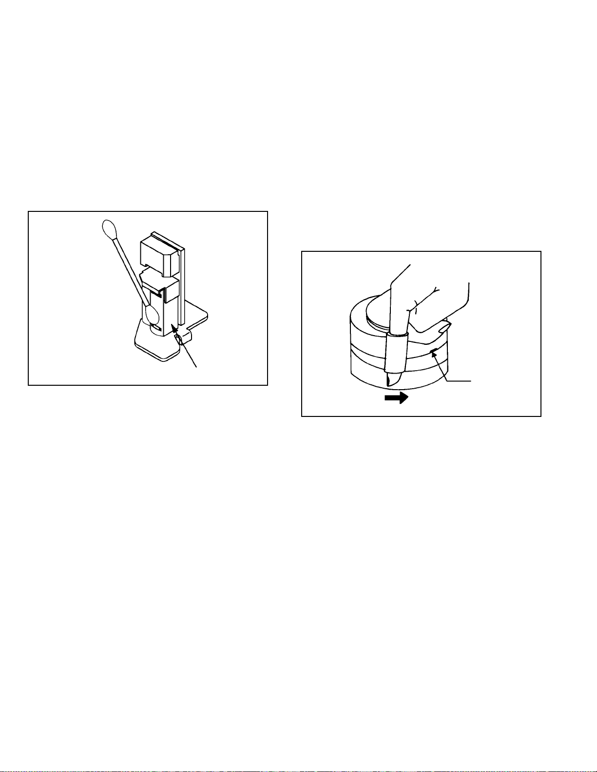
CLEANING
NOTE
After cleaning the heads with isopropyl alcohol, do not
run a tape until the heads dry completely. If the heads are
not completely dry and alcohol gets on the tape, damage
may occur.
1. AUDIO CONTROL HEAD
Clean the Audio Control Head with the cotton stick
soaked by alcohol. Clean the full erase head in the same
manner. (Refer to the figure below.)
2. TAPE RUNNING SYSTEM
When cleaning the tape transport system, use the gauze
moistened with isopropyl alcohol.
3. CYLINDER
Wrap a piece of chamois around your finger. Dip it in
isopropyl alcohol. Hold it to the cylinder head softly.
Turn the cylinder head counterclockwise to clean it (in the
direction of the arrow). (Refer to the figure below.)
NOTE
Do not exert force against the cylinder head. Do not move
the chamois upward or downward on the head.
Use the chamois one by one.
Audio Control Head
Cylinder Head
1-16
Page 23
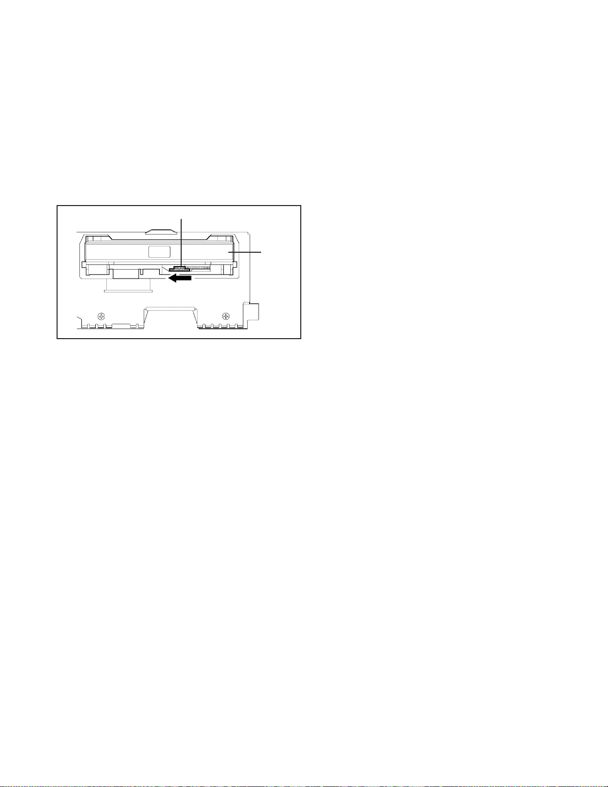
PECULUIAR SER VICE
1. DVD SECTION
DISC REMOVAL METHOD AT NO POWER SUPPLY
1. Remove the Top Cabinet and Front Cabinet.
(Refer to item 1 of the DISASSEMBLY INSTRUCTIONS.)
2. Rotate the white gear of Deck CD section in the direction of
the arrow by hand, remove the disc from Deck CD.
(Refer to Fig. 3-1)
Gear (White)
Deck CD
Fig. 3-1
1-17
Page 24

ELECTRICAL ADJUSTMENT PARTS LOCATION GUIDE (WIRING CONNECTION)
CP502
CP503
AC IN
POWER PCB
TU301
TP3002
TP101
J8003
TP8001
J8004
J8001
J8008
J8005
VCR MT PCB
J8006
CP101
J8009
C
D
1
0
2
A/C HEAD
J8007
TP3001
OS8001
V651
CP1701
CP8001
CP8002
CP651
CD651
CD502
CD8501
CD503
CD8002
DECK CD
CP8502
CD4001
CD4002
CP681
OPERATION PCB
CP4001
CP4002
MPEG PCB
1-18
Page 25

2. VHS SECTION
SERVICING FIXTURES AND TOOLS
PECULUIAR SER VICE
VHS Alignment Tape
MHP & MHP-L
Torque Tape Short Jumper
MECHANISM ADJUSTMENT PARTS LOCATION GUIDE
Torque Gauge
PUJ48075-2
Roller Driver
PTU94002-2
X-JG153 X Value Adjustment
Screwdriver
4
5
6
3
2
1
8910
1. Tension Connect
2. Tension Arm
3. Guide Roller
4. Audio/Control Head
5. X value adjustment driver hole
6.
P4 Post
7.
T Brake Spring
8.
T Reel
9.
S Reel
10.
Adjusting section for the Tension Ar m position
7
1-19
Page 26

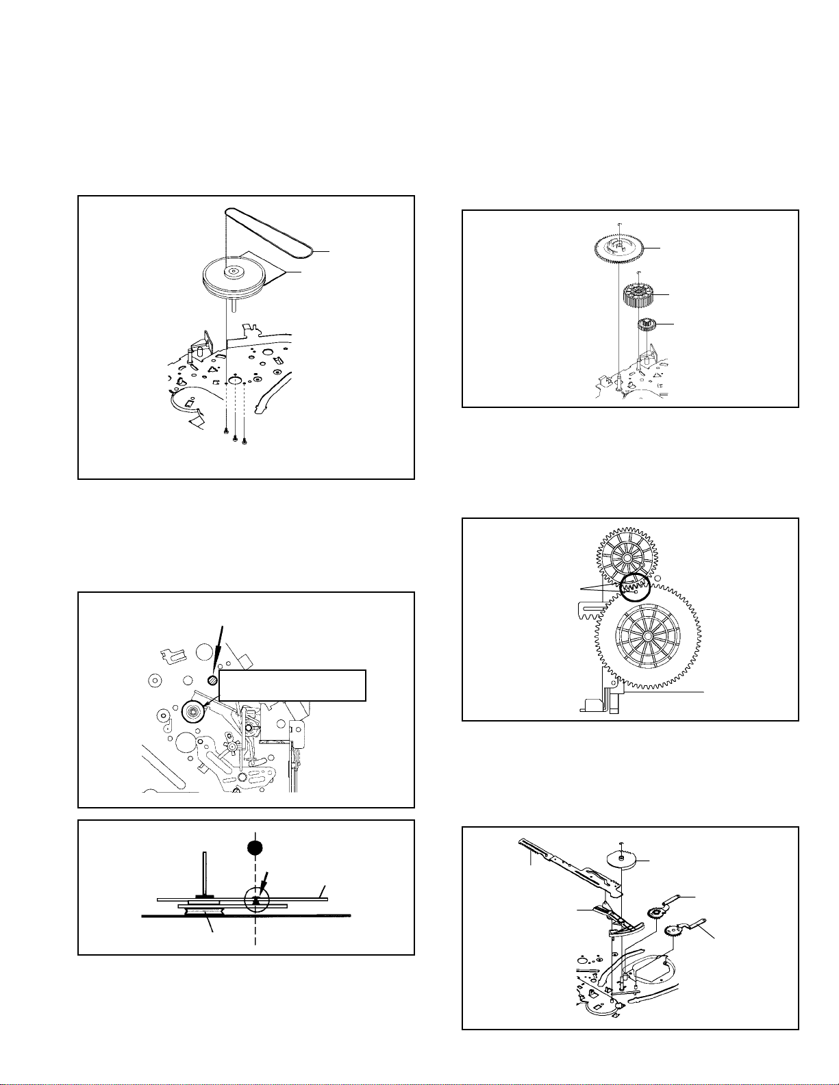
MECHANICAL ADJUSTMENTS
TAPE REMOVAL METHOD AT NO POWER SUPPLY
Remove the Top Cabinet, Front Cabinet, DVD Block, Power
1.
PCB and Center Angle and the Fig. A below can be seen.
(Refer to item 1 of the DISASSEMBLY INSTRUCTIONS.)
Remove the screw 1 of the VCR Deck and remove the
2.
Loading Motor. (Refer to Fig. B)
Rotate the Pinch Roller Cam in the direction of the arrow by
3.
hand to slacken the Video Tape.
Rotate the Clutch Ass'y either of the derections to wind the
4.
Video Tape in the Cassette Case.
Repeat the above step 3~4. Then take out the Video Cassette
5.
from the Deck Chassis. Be careful not to
scratch on the tape.
1. CONFIRMATION AND ADJUSTMENT
Read the following NOTES before starting work.
• Place an object which weighs between 450g~500g on the
Cassette Tape to keep it steady when you want to make
the tape run without the Cassette Holder. (Do not place
an object which weighs over 500g.)
1-1: CONFIRMATION AND ADJUSTMENT OF TENSION
POST POSITION
1.
Set to the PLAY mode.
2.
Adjust the adjusting section for the Tension Arm position
so that the Tension Arm top is within the standard line of
Main Chassis.
3.
While turning the S Reel clockwise, confirm that the edge
of the Tension Arm is located in the position described
above.
Standard line of Main Chassis
T ension Arm
0.5mm (Adjusting range)
Fig. 1-1-A
Loading Motor
Screw 1
Pinch Roller Cam
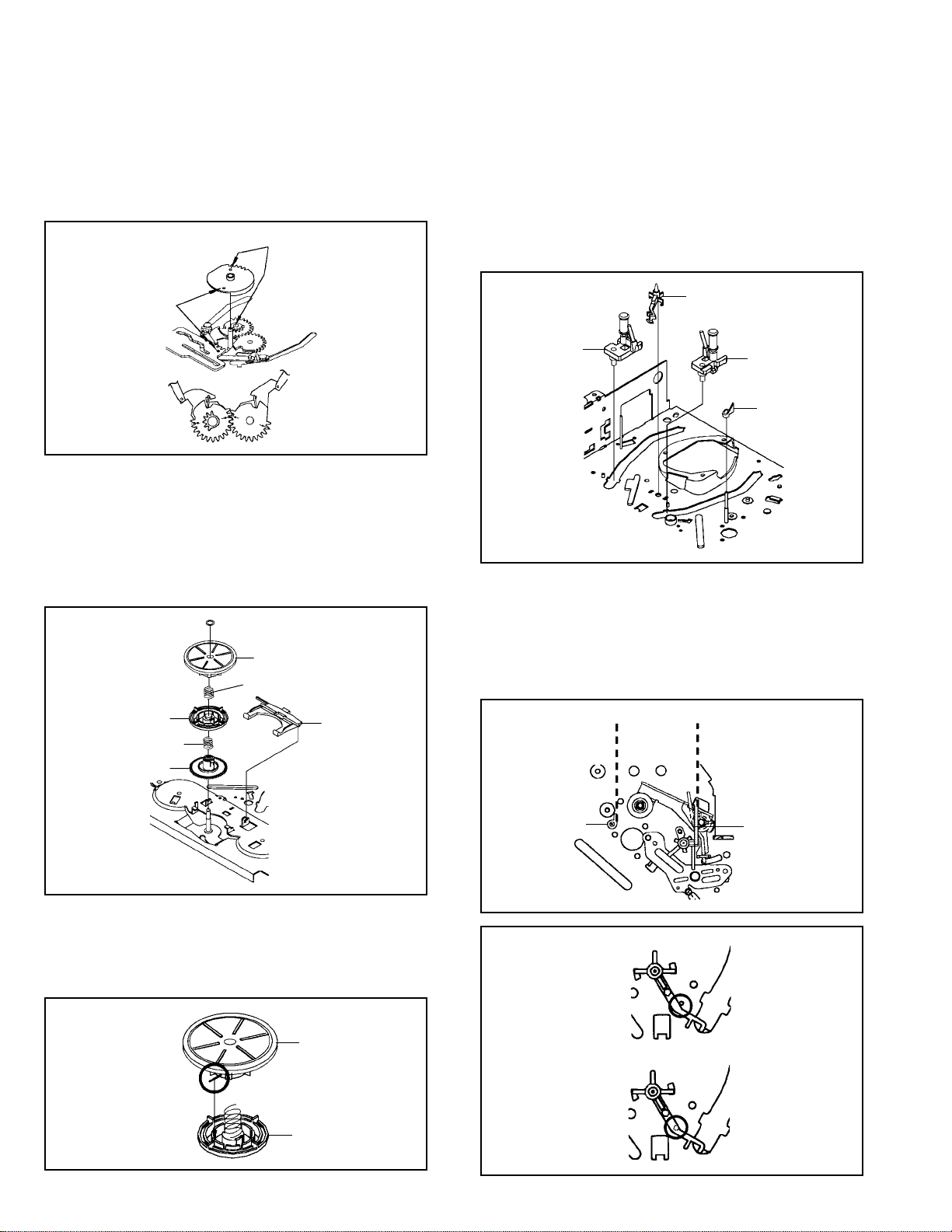
Main Cam
1-20
Main Chassis (Front Side)
Fig. A
Capstan DD Unit
Clutch Ass'y
Fig. B
Adjusting section for the
Tension Arm position
Tension Band
The Tension Arm top will
move to the inside direction
of the Main Chassis.
Bend
The Tension Arm top will
move to the outside direction
of the Main Chassis.
Fig. 1-1-B
1-2: CONFIRMATION OF PLAYBACK TORQUE AND
BACK TENSION TORQUE DURING PLAYBACK
1.
After confirmation and adjustment of Tension Post
position (Refer to item 1-2), load the cassette type
torque tape and set to the PLAY mode.
2.
Confirm that the right meter of the torque tape indicates
50~90gf•cm during playback in SP mode.
3.
Confirm that the left meter of the torque tape indicates
25~40gf•cm during playback in SP mode.
1-3: CONFIRMATION OF VSR TORQUE
1.2.Install the Torque Gauge on the S Reel. Set to the Picture
Search (Rewind) mode. (Refer to Fig.1-4-B)
Then, confirm that it indicates 120~180gf•cm.
NOTE
Install the Torque Gauge on the reel disk firmly. Press the
REW button to turn the reel disk.
Page 27

MECHANICAL ADJUSTMENTS
1-4: CONFIRMATION OF REEL BRAKE TORQUE
(S Reel Brake) (Refer to Fig. 1-4-B)
1.
Once set to the Fast Forward mode then set to the Stop
mode. While, unplug the AC cord when the Pinch Roller
Block is on the position of Fig. 1-4-A.
2.
Move the Idler Ass’y from the S Reel.
3.
Install the Torque Gauge on the S Reel. Turn the Torque
Gauge clockwise.
4.
Then, confirm that it indicates 60~100gf•cm.
(T Reel Brake) (Refer to Fig. 1-4-B)
1.
Once set to the Fast Forward mode then set to the Stop
mode. While, unplug the AC cord when the Pinch Roller
Block is on the position of Fig. 1-4-A.
2.
Move the Idler Ass’y from the T Reel.
3.
Install the Torque Gauge on the T reel. Turn the Torque
Gauge counterclockwise.
4.
Then, confirm that it indicates 30~50gf•cm.
Stop at this position.
The position at
STOP mode.
Capstan DD Unit
The position at FF mode.
Cassette Holder Ass’y
Pinch Roller Block
Cassette Opener
Fig. 1-4-A
2. CONFIRMATION AND ADJUSTMENT OF TAPE RUNNING MECHANISM
Tape Running Mechanism is adjusted precisely at the
factory. Adjustment is not necessary as usual. When you
replace the parts of the tape running mechanism because of
long term usage or failure, the confirmation and adjustment
are necessary.
2-1: GUIDE ROLLER
1.
Playback the VHS Alignment Tape (MHP).
2.
Connect CH-1 of the oscilloscope to TP101 (Envelope)
and CH-2 to TP3002 (SW Pulse).
3.
Press and hold the Tracking-Auto button on the remote
control more than 2 seconds to set tracking to center.
4.
Trigger with SW Pulse and observe the envelope. (Refer
to Fig. 2-1-A)
5.
When observing the envelope, adjust the Roller Driver
(PTU94002) slightly until the envelope will be flat.
Even if you press the Tracking Button, adjust so that
flatness is not moved so much. (Refer to Fig. 2-1-B)
6.
Adjust so that the A : B ratio is better than 3 : 2 as shown
in Fig. 2-1-C, even if you press the Tracking Button to
move the envelope (The envelope waveform will begin to
decrease when you press the Tracking Button).
7.
Adjust the PG shifter during playback.
(Refer to the ELECTRICAL ADJUSTMENTS)
NOTE
After adjustment, confirm and adjust A/C head.
(Refer to item 2-2)
Torque Gauge
Torque Gauge
S Reel
T Reel
Fig. 1-4-B
NOTE
If the torque is out of the range, replace the following parts.
Check item
1-3
1-4
S Reel side:
Replacement Part
Idler Ass’y/Clutch Ass’y
S Reel/Tension Band/Tension
Connect/Tension Arm Ass’y
T Reel side:
T Reel/T Brake Band//T Brake
Spring/T Brake Arm
CH-1
Envelope
(TP101)
CH-2
SW Pulse (TP3002)
Improper
(a) Guide roller
(b) Guide pole
Entrance
Max
A B
CH-1
Track
A : B ≥
CH-2
Track
3 : 2
Fig. 2-1-A
Proper
Fig. 2-1-B
Exit
Max
Fig. 2-1-C
1-21
Page 28

MECHANICAL ADJUSTMENTS
2-2: CONFIRMATION AND ADJUSTMENT OF AUDIO/
CONTROL HEAD
When the Tape Running Mechanism does not work well,
adjust the following items.
1.
Playback the VHS Alignment Tape (MHP).
2.
Confirm that the reflected picture of stamp mark is
appeared on the tape prior to P4 Post as shown in Fig. 2-
2-A.
a)
When the reflected picture is distorted, turn the screw
1 clockwise until the distortion is disappeared.
b)
When the reflected picture is not distorted, turn the
screw 1 counterclockwise until little distortion is
appeared, then adjust the a).
3.
Turn the screw 2 to set the audio level to maximum.
4.
Confirm that the bottom of the Audio/ Control Head and
the bottom of the tape is shown in Fig. 2-2-C.
c)
When the height is not correct, turn the screw 3 to
adjust the height. Then, adjust the 1~3 again.
Audio/Control Head
Reflected picture of
Stamp Mark
P4 Cap
2-3: TAPE RUNNING ADJUSTMENT
(X VALUE ADJUSTMENT)
1.
Confirm and adjust the position of the Tension Post.
(Refer to item 1-1)
2.
Adjust the Guide Roller. (Refer to item 2-1)
3.
Confirm and adjust the Audio/Control Head.
(Refer to item 2-2)
4.
Connect CH-1 of the oscilloscope to TP3002, CH-2 to
TP101 and CH-3 to HOT side of Audio Out Jack.
5.
Playback the VHS Alignment Tape (MHP).
6.
Press and hold the Tracking-Auto button on the remote
control more than 2 seconds to set tracking to center.
7. Set the X Value adjustment driver (X-JG153) to the 4 of
Fig. 2-2-B. At first, turn the Audio/Control Head position
fully toward the capstan side. Then adjust X Value to turn
it back gradually toward the cylinder side and stop on the
second peak point position of the envelope.
Play MHP
Waveform output
X-value adjustment point
Drum side Control head position Capstan side
Play MHP-L
Audio/Control Head
3
2
Audio/Control Head
Tape
Stamp Mark
1
4
Fig. 2-2-A
Fig. 2-2-B
0.25±0.05mm
Fig. 2-2-C
Maximum
Perform tracking operation and confirm the envelope is
8.
maximum on the tracking center position.
Playback the VHS Alignment Tape (MHP-L).
9.
Perform tracking operation and confirm the envelope is
10.
maximum on the tracking center position. If envelop is not
maximum, should be fine-tune the X-VALUE.
Fig. 2-3
1-22
Page 29

ELECTRICAL ADJUSTMENTS
Read and perform this adjustment when repairing the
circuits or replacing electrical parts or PCB assemblies.
1. BASIC ADJUSTMENT
1-1: SWITCHING POINT CONDITIONS
MODE-PLAYBACK
Input Signal-Alignment Tape (MHP)
INSTRUCTIONS
Connect CH-1 on the oscilloscope to TP3002 and CH-2
1.
to TP8001.
Playback the alignment tape. (MHP)
2.
Press and hold the Tracking-Auto button on the remote
3.
control more than 2 seconds to set tracking to center.
Press both CH UP button on the set and the STOP button
4.
on the set for more than 2 seconds.
ELECTRICAL ADJUSTMENT PARTS LOCATION GUIDE
6.5H
6.5H
CH-2
CH-1
CH-2
CH-1
Fig. 1-1-A
Fig. 1-1-B
TU301
TP8001
TP101
TP3002
J8001
J8008
J8006J8009J8007OS8001
VCR MT PCB
TP101 : Envelope
TP3001: Service Mode
TP3002: Switching Pulse
TP8001: Switching Point
TP3001
J8003 J8004 J8005
V651
1-23
Page 30

IC DESCRIPTIONS
SYSCON PCB OEC0110A (IC3001)
No. PORT PIN NAME I/O DESCRIPTION
1 SVSS SVSS - Ground.
2 CTL_REF CTL_REF Output terminal for CTL amp REF (1/2 SVCC)
3 CTL-H(+) CTL-H(+) Input and output terminal of Control Head.
4 CTL-H(-) CTL-H(-) Input terminal of Control Head.
5 CTL_BIAS CTL_BIAS Output terminal for bias.
6 CTL_FB CTL_FB Input terminal for CTL feedback
7 CTL_AMP(O) CTL_AMP(O) Output terminal for amp out.
8 CTL_AMP(I) CTL_AMP(I) Input terminal for CTL shumit amp .
9 CFG CFG Input terminal for CAPSTAN FG signal detection.
10 SVCC SVCC + 5V (Servo)
11 AFC_PC AFC_PC AFC oscilator (external circuit).
12 AFC_OSC AFC_OSC AFC oscilator (external circuit).
13 AFC_LPF AFC_LPF LPF connection for AFC OSC.
14 CSYN/HSYN CSYNC OUT Output terminal for composite SYNC.
15 VLPF/VSYN VSYNC IN Input terminal for composite SYNC.(from 14pin)
16 CV_IN2 CV_IN2 IN Composite Video input terminal.(for data slicer)
17 CV_IN1 CV_IN1 IN Composite Video input terminal.(for OSD)
18 OSD VCC OSDVCC - + 5V
19 CV_OUT CV_OUT OUT Composite Video output.(with OSD)
20 OSD_VSS OSD_VSS - Ground.
21 4/2 FSC_OUT 4/2 FSC_OUT OUT 2 FSC pulse.
22 4/2 FSC_IN 4/2 FSC_IN IN 2 FSC pulse.
23 AVSS AVSS - Ground.
24 AN-B VIDEO_ENV IN Input terminal of video RF envelope.
25 AN-A BOT-H IN Tape start sensor input signal.
26 AN-9 EOT-H IN Tape end sensor input signal.
27 AN8 MS_SEN-B IN Input terminal of mecha state sensor.
28 P07/AN7 MS_SEN-A IN
29 P06/AN6 KEY-B IN Main unit key input.
30 P05/AN5 KEY-A IN
31 P04/AN4 STEREO_SEL IN Input terminal for the judgement of voice reception condition.
32 P03/AN3 HI-FI_ENV IN Input terminal of HiFi RF envelope.
33 P02/AN2 AFT-S_CURVE IN AFT S CURVE input for tuner.
34 P01/AN1 SERVICE IN Input terminal for Service Mode.
35 P00/AN0 TAB SW IN Input terminal for judge the tape if it has TAB or not.
36 AVCC AVCC - ON/OFF control Micon AD section.
37 P10/IRQ0 POWER_FAIL IN Input terminal of Power fail signal.
38 P11/IRQ1 CFG IN2 IN Input terminal for CAPSTAN FG signal detection.
39 P12/IRQ2 NC IN Not used.(for FZTAT)
1-24
Page 31

IC DESCRIPTIONS
SYSCON PCB OEC0110A (IC3001)
No. PORT PIN NAME I/O DESCRIPTION
40 P13/IRQ3 VIDEO_MUTE OUT H for at AUTO_CLOCK in POWER OFF. L for except above case.
41 P14/IRQ4 POWER_ON_L OUT For control the user power switch ON/OFF.
42 P15/IRQ5 POWER ON-H OUT For control the user power switch ON/OFF.
43 P16/IC REM_IN IN Receive the remote control signal.
44 P17/TMOW DVD RESET OUT For control the DVD RESET.
45 P67/RP7/TMB NC OUT Not used.
46 P66/RP6/ADTRG DVD LED OUT The DVD LED light-up/put-off control output.
47 P65/RP5 VCR LED OUT The VCR LED light-up/put-off control output.
48 P64/RP4 GRID1 OUT LEM(LED Module) control terminal.
49 P63/RP3 GRID2 OUT LEM(LED Module) control terminal.
50 P62/RP2 GRID3 OUT LEM(LED Module) control terminal.
51 P61/RP1 GRID4 OUT LEM(LED Module) control terminal.
52 P60/RP0 GRID5 OUT LEM(LED Module) control terminal.
53 P37/TM0 Y/C CLOCK OUT Control terminal for Y/C. (CLOCK).
54 P36/BUZZ Y/C DATA OUT Control terminal for Y/C.(DATA).
55
56 VCC VCC - Power of CPU.
57 VSS VSS - Ground.
58
59
60 P25 SEG4 OUT LEM(LED Module) control terminal.
61 P24/SCL1 IIC CLK OUT CLOCK terminal for IIC BUS communication.
62 P23/SDA1 IIC DATA OUT/IN DATA terminal for IIC BUS communication.
63 P22/SCK1 SEG5 OUT LEM(LED Module) control terminal.
64 P21/SO1 TX OUT Input terminal for DVD communication.(asynchronous)
65 P20/SI1 RX IN Output terminal for DVD communication.(asynchronous)
66 P47/RPTRG SEG6 OUT LEM(LED Module) control terminal.
67 P46/FTOB SEG7 OUT LEM(LED Module) control terminal.
68 P45/FTOA SEG8 OUT LEM(LED Module) control terminal.
69 P44/FTID REEL-S IN Input terminal of reel sensor supply.
70 P43/FTIC REEL-T IN Input terminal of reel sensor take up.
71 P42/FTIB SEG9 OUT LEM(LED Module) control terminal.
72 P41/FTIA JUST_CLOCK IN not used.
73 P40/PWM14 SEG10 OUT LEM(LED Module) control terminal.
74 FEW FEW IN FZTAT Write protect.
75 X2 X2 OUT Subclock pulse(32.768KHz)
76 X1 X1 IN
77 /RESET /RESET IN RESET will be done when the voltage goes to HIGH after the
P35 SEG1 OUT/IN
P27 SEG2 OUT
P26 SEG3 OUT
LEM(LED Module) control terminal.
LEM(LED Module) control terminal.
LEM(LED Module) control terminal.
reset signal.
1-25
Page 32

IC DESCRIPTIONS
SYSCON PCB OEC0110A (IC3001)
No. PORT PIN NAME I/O DESCRIPTION
78 OSC1 OSC1 IN Connect the main crystal(10MHz)
79 DVSS VSS - Ground.
80 OSC2 OSC2 OUT Connect the main crystal(10MHz)
81 VCL VCL IN Connect the capacitor
82 MD0 MD0 IN FZTAT Write MODE.
83 P34/PWM2 NC OUT not used.
84 P33/PWM1 CAP_LIMIT OUT Switch the maximum output current of the Capstan Motor.
85 P32/PWM0 T.AUDIO_MUTE OUT H for at PLAY in VCR MODE. L for except above case.
86 P31/SV2 TV/VCR OUT H for at RF modulator ON. L for except above case.
87 P30/SV1 POWER_MUTE OUT audio mute at POWER ON/OFF.
88 P70/PPG0 SURROUND_ON OUT Control the surround IC.
89 P71/PPG1 NC OUT Not used.
90 P72/PPG2 NC OUT Not used.
91 P73/PPG3 AV SW_2 OUT Control rear/front video signal.(at AV X 2)
92 P74/PPG4/RP8 AV SW_1 OUT Control DVD/VCR video/audio signal.
93 P74/PPG5/RP9 Y/C CS OUT Control terminal for Y/C. (CHIP SELECT).
94 P76/PPG6/RPA CENTER LED OUT The CENTER LED light-up/put-off control output.
95 P77/RPG7/RPB AUDIO_OUT_MUTE OUT H for at AUDIO MUTE . L for except above case.
96 P80/YCO V_REC_ST-H OUT On control of A/V recording(Whole width erase) circuit.
97 P81/EXCAP/YBO LDM CTL OUT Loading motor control terminal.
98 P82/EXCTL CAP_FWD-H OUT Capstan forward and backward command.
99 P83/C,ROT/R C.ROTARY OUT Color Rotary Control output.
100 P84/H.AMP/G H.AMP.SW OUT Switching output of Head Amp SW.
101 P85/COMP/B COMP IN Comparison results input of Playback Envelope level on SP/LP
heads (4 heads).
102 P86/EZTTRG CAP_FULL OUT Output the HIGH during the acceleration force of capstan motor at
SLOW mode.
103 P87/DPG CYL_SPEED_UP OUT Output terminal for correct cylinder during SLOW.
104 DFG D FG/PG IN Input terminal for DRUM FG signal detection.
105 VIDEO_FF H.SW OUT Output terminal of Video Head SW.
106 AUDIO_FF HI-FI H.SW OUT Output terminal of HI-FI Head SW.
107 DRUM_PWM DRUM_PWM OUT PWM output of Cylinder control.
108 CAP_PWM CAP_PWM OUT PWM output of Capastan control.
109 V-PULSE DUMMY_V-SYNC OUT Virtual V Pulse output.
110 SV VSS SV VSS - Ground.
111 C.SYNC_IN SYNC IN Input terminal for composite SYNC.
112 VCC VCC(SV) - + 5V
1-26
Page 33

VCR MT PCB IC3001 (OEC0110A)
DPG 104 PIN
DFG 104 PIN
SERVO TIMING CHART
24 Cycle
H. SW. P 105 PIN
V-SYNC (E-E) 111 PIN
REC CTL (REC)
7 PIN
V-SYNC (TRICK PB)
109 PIN
• WAVEFORM CHANGES DEPENDED ON THE TAPE SPEED
CH 1
CH 2
1-27
Page 34

C
Y
MECHANISM TIMING CHART
Please see the list below for the operational timing and the mode sensor output of the main parts on each mechanism modes.
MECHANISM MODE UNLOAD STOP3
Mode Dealing
Directions
Revolutional Angle of
MAIN CAM
Moving Quantity of
MAIN ROD (mm)
MODE MS-1
SENSOR
HIGH
LOW
EJECT
0
STBY
15
3
206.3100
180
Output
HIGH
MS-2
LOW
INCLINED BASE S/T UNIT
PINCH ROLLER BLOCK
P5 ARM ASS'Y (T BRAKE:LOW)
TENSION LEVER
TENSION ARM ASS'
(S REEL BRAKE)
VSR
S BRAKE:LOW
255
26.5
PRESS
PRESS
P5-ON (T BRAKE HIGH)
BRAKE-ON
PBF.SLOW
S BRAKE:HIGH
FF/REWSTOP2
323.8303.7272.2226.4
38.53529.521.5
TENSION CONNECT
(S REEL BRAKE)
T BRAKE ARM
(T REEL BRAKE)
LUTCH LEVER
LINK UNIT
FLAP LEVER
BRAKE-ON
BRAKE-ON
CLUTCH-ON
UP
BRAKE-ON
DIRECT
PRESS
1-28
Page 35

(VCR SECTION)
POWER DOES NOT TURN ON
TROUBLESHOOTING CUIDE
Does display light?
YES
Is there voltage at
pin 42 of IC 3001?
NO
Check IC3001.
NO
YES
Is the voltage at pin 14
of CP502 about 5.2V?
YES
Check IC3001.
NO
Check pin 13 of T501
and peripheral circuit.
Check Q506,Q504.
1-29
Page 36

THE POWER SUPPLY CUT
Inserting a casette
and push play button.
TROUBLESHOOTING CUIDE
Does the power cut
after 3 seconds?
NO
Does the power cut
after about 6 seconds?
NO
Does intermittently
the power cut?
NO
Check the POWER BLOCK.
YES
YES
YES
Check CAPSTAN DD UNIT
and CYLINDER UNIT.
Check Q3001,Q3002
and CAPSTAN BELT.
Check Q3001,Q3002,IC3001
and sag of CAPSTAN BELT.
1-30
Page 37

AUDIO SHAKES
TROUBLESHOOTING CUIDE
Is AUDIO HEAD
scratched?
NO
At playback,is input about
4.5Vp-p of a rectangular
wave at pin 9 of IC3001?
YES
At playback,is pin 5 of
CP3001 3.5V?
YES
Check AUDIO BLOCK.
YES
NO
NO
Change AUDIO HEAD.
Change CAPSTAN DD UNIT.
Check IC3001.
1-31
Page 38

The CASSETTE TAPE
CAN NOT BE INSERTED
TROUBLESHOOTING CUIDE
Does WORM GEAR of
cassette loading block
move?
YES
When a CASSETTE can
not inserted,is pin 25 of
IC3001 5V ?
YES
When a CASSETTE is
inserted,is pin 8 of
CP3001 12.6V ?
NO
When a CASSETTE is
inserted,is pin 5 of
IC3001 5V ?
NO
NO
YES
NO
Check WORM GEAR
of cassette loading block.
Check LED of DECK,
PHOTO SENSOR.
Change
LOADING MOTOR.
Change IC3001.
YES
Check circuit of loading motor.
1-32
Page 39

When inserting a CASSETTE,
it ejects immediately.
TROUBLESHOOTING CUIDE
Does another CASSETTE
insert?
YES
Does SW3001 and
REC LEVER
correctly set ?
YES
After inserting
CASSETTE,is pin 35
of IC3001 0V ?
YES
Check IC3001.
NO
NO
NO
Defective CASSETTE
or cassette loading
block.
Correctly SW3001
and REC LEVER set.
Check SW3001.
1-33
Page 40

Can not FF/REW
TROUBLESHOOTING CUIDE
at pin98 of IC3001
change?
YES
Check DECK MECHANISM.
WHEN PLAYBACK,FF OR REW
MODE IS ACTIVE ,UNIT STOPS
IMMEDIATELY
Does CAPSTAN DD
MOTOR rotate?
NOAt FF/REW,does voltage
NO
Check line of IC3001
at pin29 and pin30.
Refer to section "CAPSTAN
DD MOTOR NOT
ROTAING".
1-34
YES
Is there REEL SENSOR
PULSE signal at pin 69
and pin 70 of IC3001
YES
Change IC3001
NO
Check Q3001 and Q3002
Page 41

TAPE loading is ok,but
unloads immediately.
TROUBLESHOOTING CUIDE
Does CYLINDER
rotate?
YES
Is there HEAD SW
PULSE at TP3002
YES
NO
NO
Is the voltage
at pin 2 of CP502
12.6V ?
YES
At play,is the voltage
at pin 12 of CP3001 2.6V ?
YES
Change CYLINDER unit.
NO
Is PG PULSE signal
inputted to pin 104
of IC3001 ?
YES
NO
NO
Check power block.
Check Q3001 and Q3002
Change IC3001.
1-35
Page 42

At play,the picture
jitters vertical minutely
TROUBLESHOOTING CUIDE
Is FG wave of CP3001
at pin 11 5V ?
5V
YES
Is pin 12 of CP3001 2.6V ?
YES
Change CYLINDER MOTOR
NO
NO
Change
CYLINDER MOTOR
Change IC3001
Auto tracking
does not operate
In auto tracking,is the
voltage at pin 24 of IC3001
more than DC 0.2V?
CHANGE IC3001
1-36
YES
NO
Does the CLT pulse
signal (about 2.5Vp-p)
appear at pin 7 of IC3001.
2.5Vp-p
YES
NO
Check CONTROL HEAD.
Page 43

TROUBLESHOOTING CUIDE
AT PLAY,PICTURE JITTERS
HORIZONTALLY
NO
Does a noise on the picture
appear?
YES
By adjusting the MANUAL
TRACKING UP/DOWN
BUTTONS,will the line
disappear?
YES
Is a height of GUIDE POST
maximum?
YES
Is PG SHIFTER
adjustment 6.5H?
NO
NO
NO
Check P/B ENVELOPE.
The height of GUIDE POST
readjust
Adjust PG SHIFTER.
YES
Is a wave of PB-Y unusual?
YES
Change IC1001
NO
Change IC101
1-37
Page 44

AT PLAYBACK,THE PICTUER
DOES NOT APPEAR
TROUBLESHOOTING CUIDE
Does E-E picture
appear?
YES
Is there video signal
of IC101 at pin 26?
YES
Is there video signal
of IC8001 at pin 6?
YES
Is there video signal of
IC3001 at pin 19?
NO
NO
NO
NO
Is the voltage of IC101 at
pin 44,45,52 and 68 5V?
YES
NO
Check POWER BLOCK.
Change IC101
Change IC8001
Change IC3001
1-38
YES
Check jack J8001
Page 45

AT PLAYBACK,THE COLOR DOES
NOT APPEAR
TROUBLESHOOTING CUIDE
Is there color signal in
video signal at pin 26 of
IC101
YES
Check pin 19 of IC3001
NO COLOR DURING SELF
RECORDING AND PLAYBACK
NO
Is there video signal at pin
26 of IC101
YES
Change IC101
NO
Change X'tal
Is there CHROMA signal at
pin 30,32 of IC101
YES
Is there CHROMA signal at
pin 26 of IC101
YES
Check circuit around of J8001
NO
NO
Check TU301,J8003,
circuit around it.
Change IC101
1-39
Page 46

AT PLAYBACK AND RECORDING,
CYLINDER MOTOR UNLOAD
TROUBLESHOOTING CUIDE
Is the voltage at pin 8 of
CP3001 about DC12.6V?
YES
In playback,is at pin 12 of
CP3001 about DC2.6V?
YES
Change CYLINDER MOTOR.
PLAYBACK PICTURE IS NOISY
(EVEN AFTER CLEANING HEADS)
NO
NO
Check at 12.6V line,
power block.
Check IC3001.
Is noisy a wave of video
signal at pin 26 of IC101?
YES
Is noisy a wave of video signal
of EMITTER of Q8004
NO
Check J8001
1-40
NO
YES
Check CYLINDER.
Check Q8004
Page 47

AT PLAY,AUDIO DOES NOT
APPEAR
TROUBLESHOOTING CUIDE
At E-E,does audio appear?
YES
Is the voltage at pin 6 of
IC101 about 2.5V?
YES
Is there audio signal at pin
10 of IC101?
YES
Is there audio signal at pin
22,24 of IC701?
NO
NO
NO
YES
Refer to section"E-E DOES
NOT APPEAR".
Check C4024 and around
circuit of it.
Check circuit around at pin
10 of IC101.
Check circuit around at pin
22,24 of IC701.
NO
Check whether there are not a
damage ,dirt in AUDIO HEAD
1-41
Page 48

THE AUDIO CAN NOT
RECORD
TROUBLESHOOTING CUIDE
Is bias level at L101 OK?
YES
Is there audio signal at
pin 76,78 and 80 of IC101?
NO
NO
In starting recording,
is there sine wave at
pin 7 of IC101?
YES
Check disconnection
and short of L101.
NO
Check POWER BLOCK and
voltage of base of Q103.
Check IC701 and
the circuit from TUNER
or audio input juck to IC701 .
YES
Is there voltage
of base of Q103
about 5V?
YES
Is there sine wave at
pin 5 of L101?
YES
Check lead wire of A/C HEAD
and CONNECTOR.
NO
NO
Change Q103.
Change L101.
1-42
Page 49

THE CASSETTE INSERT,BUT
THE TAPE DOES NOT MOVE
TROUBLESHOOTING CUIDE
Does the mode
appear at display?
YES
Does operate with
remote control?
YES
Check operation PCB.
CAPSTAN DD MOTOR NOT
ROTATING
NO
NO
Check LOADING MOTOR and
MODE SENSOR
RELATION DEPARTMENT.
Check IC3001.
In playback,is there voltage at
pin 2 of CP3001 27V?
YES
In playback,is there voltage at
pin 102 of IC3001 2.5V?
YES
DD MOTOR rotate now?
If not,replace it.
NO
NO
Check POWER BLOCK.
Change IC3001.
1-43
Page 50

RECORDING MECHANISM WORKS,
BUT NO VIDEO RECORD FROM
INPUT JACK OR TUNER
TROUBLESHOOTING CUIDE
Is there video signal at
pin 30,32 of IC 3001?
YES
Is the BASE of
Q103 5V?
YES
Is there video signal
at pin 26 of IC101?
NO
NO
NO
Is the voltage at pin 96
of IC3001 5V?
YES
NO
Check cricuit of video signal from
VIDEO IN or
TUNER to IC3001.
Change IC3001
Change IC101
Check CYLINDER UNIT and
circuit around of CP101
1-44
YES
Page 51

E-E DOES NOT APPEAR
(THE PICTURE DOES NOT
APPEAR FROM TUNER)
TROUBLESHOOTING CUIDE
Does normality AUDIO JACK
CONNECT?
YES
Are there thevoltage
of MB(5V),PB(5V),
TU(32V) of TU301?
YES
Check the picture.
Is there video signal at
pin 24 of TU301?
NO
NO
NO
Connection is done over again
Check POWER BLOCK.
Change TU301.
YES
Is there video signal
at pin 26 of IC101?
YES
Is there video signal at
pin 19 of IC301?
YES
Check J8001.
NO
NO
Change IC101.
Change IC301.
1-45
Page 52

E-E AUDIO(MONO)
DOES NOT APPEAR
TROUBLESHOOTING CUIDE
Does E-E AUDIO
(STEREO) appear?
YES
Is the voltage at pin 7
of IC101 5V?
YES
Is the voltage at pin 95 of
IC3001 5V?
NO
Is there audio signal at
pin 10,15 of IC701?
NO
NO
YES
NO
Refer to section "E-E AUDIO
(STEREO) DOES NOT APPEAR".
Check POWER BLOCK.
Change IC301.
Change IC101.
YES
Is there audio signal at
pin 61 of IC701?
YES
Check circuit around of J8001.
NO
Change IC701.
1-46
Page 53

E-E AUDIO(STEREO)
DOES NOT APPEAR
TROUBLESHOOTING CUIDE
Is the voltage at pin
25,40,51 of IC701 5V?
YES
Is the voltage at pin
58 of IC701 12V?
YES
Is there video signal at
pin 10,15 of IC701?
YES
Is there video signal at
pin 53,57 of IC701
NO
NO
NO
NO
Check POWER BLOCK.
Check POWER BLOCK.
Change IC101.
Change IC701.
YES
Check circuit around of J8001.
1-47
Page 54

TUNER AUDIO(MONO)
DOES NOT APPEAR
TROUBLESHOOTING CUIDE
Does E-E AUDIO
(MONO) appear?
YES
Is there video signal
at pin 48 of IC701?
YES
Is there audio signal at
pin 53,57 of IC701?
YES
Is there audio signal
a collector of Q8005
and Q8006?
NO
NO
NO
NO
Refer to section "E-E AUDIO
(MONO) DOES NOT APPEAR".
Check circuit around of TU301
at pin 22.
Change IC701.
Check IC8001 at pin 3,5.
YES
Check circuit around of J8001.
1-48
Page 55

TUNER AUDIO(STEREO)
DOES NOT APPEAR
TROUBLESHOOTING CUIDE
Does TUNER AUDIO
(MONO) appear?
YES
Does E-E AUDIO
(STEREO) appear?
YES
At the time of channel
change,does the display of a
stereo come out to the screen?
YES
Is there audio signal at
pin 48 of IC701?
NO
NO
NO
NO
Refer to section "TUNER AUDIO
(MONO) DOES NOT APPEAR".
Refer to section "E-E AUDIO
(STEREO) DOES NOT APPEAR".
Change IC701.
Check ciruit around of TU301.
YES
Is there audio signal
at pin of IC701?
YES
Is there audio signal
a collector of
Q8005 and Q8006
YES
Check circuit around of J8001.
NO
NO
Change IC701.
Check IC8001 of pin 3 and 5.
1-49
Page 56

PB AUDIO(Hi-Fi)
DOES NOT APPEAR
TROUBLESHOOTING CUIDE
Does E-E AUDIO
(STEREO) appear?
YES
Does NORMAL PB
AUDIO appear?
YES
Is there audio signal at
pin 22,24 of IC701?
YES
Is there audio signal at
pin 53,57 of IC701?
NO
NO
NO
NO
Refer to section "E-E AUDIO
(STEREO) DOES NOT APPEAR".
Refer to section "AT PLAY,
AUDIO DOES NOT APPEAR".
Check circuit of HEAD AMP
and CYLINDER UNIT.
Change IC701.
YES
Check circuit around of J8001.
1-50
Page 57

Hi-Fi AUDIO
CAN NOT RECORD
TROUBLESHOOTING CUIDE
Does E-E AUDIO appear?
YES
AT state of video recording,
is there audio signal at
pin 10 and 15 of IC701?
YES
Is there audio signal at
pin 53,57 of IC701?
YES
At recording and play,is
there signal at pin 7,8
and 9 of CP101?
NO
NO
NO
NO
Refer to section "E-E AUDIO
(MONO) DOES NOT APPEAR".
Check circuit arounf of
J8004,J8005 and TU301.
Change IC701.
Check CYLINDER UNIT.
YES
Check IC101.
1-51
Page 58

(DVD SECTION)
Deck does not accept
open/close
TROUBLESHOOTING CUIDE
Is the DVD
display out ?
YES
Can it open and close
it manually? (*1)
YES
DVD mode unstable
NO
NO
YES
Is CD503 connected
correctly ?
YES
Confirmation of the MPEG PCB
(P.CON 5V,P.CON 9V,P.CON 5V D)
Change DECK CD
"DVD mode unstable"
page reference
NO
CD503 is connected again
1-52
NO
*1:Turn GEAR of DECK CD front lower part,
to open and close TRAY manually
Change DECK CD
Page 59

DVD screen without going out
TROUBLESHOOTING CUIDE
Are CD4001,CD4002
connected correctly ?
YES
Connector on the side of
DECK CD is not
turning or short
YES
Is X1001 oscillating?
YES
NO
NO
NO
CD4001,CD4002 are
connected again
Change DECK CD
Change X1001
Are there signals at pins
24,25 of IC8501
NO
Change IC4001
YES
Change IC8501
1-53
Page 60

Do not playback DVD
TROUBLESHOOTING CUIDE
Does display "Incorrect
Disc" after reading ?
NO
When it playback dvd disc
as for SPINDLE MOTOR
is it revolve ?
YES
NO
Is CD4001 connected
correctly ?
NO
CD4001 is connected again
YESYES
Change DECK CD
Change DECK CD
Are there output signals
at pins 57,58,59 of
C8501
NO
"DVD screen without going out"
page reference
YES
Check IC8001 and
peripheral circuit.
1-54
Page 61

DVD mode unstable
TROUBLESHOOTING CUIDE
Is CD4001 connected
correctly ?
YES
Connector on the side of
DECK CD is not
turning or short
YES
Are CD8002, CD8501
connected correctly ?
YES
NO
NO
NO
CD4001 is connected again
Change DECK CD
CD8002,CD8501
are connected again
Change DECK CD
1-55
Page 62

Do not playback CD
TROUBLESHOOTING CUIDE
As for the motor is it
revolve at the time of
reading ?
YES
Connector on the side of
DECK CD is not
turning or short
YES
Are there input signals
at pin 3,4,5,6 of IC4001
YES
NO
NO
NO
Change DECK CD
Change DECK CD
Check connection of CP4002
and peripheral circuit
1-56
Change IC4001
Page 63

No digital audio on playback
TROUBLESHOOTING CUIDE
Is there waveform
at pin 3 of IC8504 ?
NO
Are there audio signals at
pin 1,4 of IC8504 ?
NO
Is there audio waveform
at pin 117 of IC4001 ?
NO
YES
YES
YES
Is there waveform
at pin 16 of CP4002 ?
Check OS8001 and peripheral
circuit of J8007
Change IC8504
Check peripheral circuit of
IC8504
YES
Change IC4001
NO
Change DECK CD
1-57
Page 64

DVD/CD ANLOG AUDIO DOES
NOT APPEAR
TROUBLESHOOTING CUIDE
Is there audio
waveform at pin 3,5 of
IC8001?
NO
Is there audio waveform
at pin 1,14 of IC8504?
NO
Is there audio waveform
at pin 3,14 of IC8007?
NO
YES
YES
YES
Check circuit around of J8001.
Change IC8504.
Check circuit around of IC8007.
Is there audio
waveform at pin 3,5
of IC8004?
Is there audio waveform
at pin 7,8 of IC8503?
Change IC8503 or IC4001.
1-58
NO
NO
YES
YES
Change IC8007.
Change IC8007.
Page 65

NO PLAYBACK PICTURE
OF Y.U.V OUT
TROUBLESHOOTING CUIDE
Is there Y.U.V waveform at
pin 42,43,44 of IC8501?
NO
Are there signals at pins
13,14,15,16,19,20
0f IC8501 ?
NO
YES
YES
Is there Y.U.V
waveform at pin 7,9
and 11 of CP8502?
NO
Check circuit around of
D8504,D8508 and D8512.
YES
Check circuit around of J8008.
Check circuit around of IC8501
Are there signals at
pins 92,94,95,96,97
99 of IC4001 ?
NO
Change IC4001 or DECK CD
YES
Change IC8501
1-59
Page 66

No playback picture of
S-VIDEO jack
TROUBLESHOOTING CUIDE
Are there Y signal at pin 59
and C signal at pin 58 of
IC8501 ?
NO
Are there waveform at
pins 13~16,19~22
of IC8501 ?
NO
Are there waveform at
pins 92,94~97,99~
101 of IC8501 ?
NO
YES
YES
YES
Check D8506 and circuit
around of D8510
Change IC8501
Check IC8501 and circuit
around of IC4001
1-60
Change IC4001
Page 67

<Reference><Reference>
GENERAL SPECIFICATIONS [HR-XVC1U]
G-1 Outline of the product DVD VIDEO PLAYER & VHS Player / Recorder
G-2 DVD System Color System NTSC
G-3 VCR System VHS Player / Recorder
System Video System NTSC
Disc DVD, CD-DA, CD-R/RW, VIDEO CD
Disc Diameter 120 mm , 80 mm
Deck Disc Loading System Front Disc Loding
Motor 3 Motors
Pick up 1-Lens 2-Beams System
Playback time (Max) DVD 1-Layer 135min (4.7GB)
DVD 2-Layer 245min (8.5GB)
CD 74min
VIDEO CD 74min
Search speed Fwd 2-20 times / 4 step (DVD, VIDEO CD)
6-16 times / 2 step (CD)
Actual 2-45 times (DVD, VIDEO CD)
4-40 times (CD)
Rev 2-20 times / 4 step (DVD, VIDEO CD)
6-16 times / 2 step (CD)
Actual 2-45 times (DVD, VIDEO CD)
4-40 times (CD)
Slow speed Fwd 1/7-1/2 times
Actual --
Rev --
Actual --
Hi-Fi STEREO Yes
NTSC PB(PAL60Hz) No
Deck DECK OVD-7
Loading System Front
Motor 3
Heads Video Head 4Head
FM Audio Head 2Head
Audio /Control Mono/Yes
Tape Rec PAL Speed NTSC SP/SLP(EP)
Fast Forward / Rewind Time (Approx.) FF:1'48"/REW:1'48"
Forward/Reverse NTSC or PAL-M SP/SLP(EP) = 3x,5x / 9x,15x
Picture Search PAL or SECAM Frame Advance 1/10
Slow Speed 1/10
G-4 Tuning Broadcasting System US System M
System Tuner and System 1Tuner
Receive CH Destination US(w/CATV)
Intermediate Picture(FP) 45.75 MHz
Frequency Sound(FS) 41.25 MHz
Preset CH RF Converter Output Yes
Stereo/Dual TV Sound US-ST
Tuner Sound Muting Yes
G-5 Power Power Source AC 120V 60Hz
Power Consumption 20 W at 120V 60Hz
Protector Power Fuse Yes
G-6 Regulation Safety UL/CSA
Erase(Full Track Erase) Yes
Play PAL -
Channel 3 or 4 ch
Level/Impedance 66 dBu / 75 Ohm
Sound Selector No
NTSC SP/SLP(EP)
with Cassette T-120
Tuning System F-Synth
Input Impedance VHF/UHF 75 OHM
CH Coverage
FP-FS 4.50 MHz
DC -
Stand by 3 W at 120V 60Hz
Per Year -- W
Radiation FCC/IC
Laser DHHS
2-69,4A,A-5~ A-1,A~I,
J~ W, W+1-W+84
4-1
Page 68

<Reference>
GENERAL SPECIFICATIONS [HR-XVC1U]
G-7 Temperature Operation 5C - 40C
G-8 Operating Humidity Less then 80% RH
G-9 Signal Video Signal Output Level 1 V p-p/75 ohm (DVD,VCR)
RGB Signal Output Level Audio Signal Input Level Microphone -
(0dB=0.775Vrms) Output Level Line -8 dBm/ 1k ohm(DVD,VCR)
Hi-Fi Audio Signal Dynamic Range : More than 90dB
G-10 On Screen Menu Yes
Display(DVD) Menu Type Character
Open Yes
Close Yes
No disc Yes
Reading Yes
Play Yes
Still/Pause Yes
Stop Yes
Prohibit Mark Yes
Step Yes
Next Yes
Back Yes
Random Yes (CD, VIDEO CD )
Repeat Yes
Slow+ ## Yes
Slow- ## No
Search+ ## Yes
Search- ## Yes
Jump Yes
Resume Yes
Title No. Yes
Chapter No. Yes
Track No. Yes
Time Yes
Sub Title No. Yes
Angle No. Yes
Vocal On/Off Yes
Audio No. Yes
Audio Stereo L/R Yes (VIDEO CD )
Zoom Yes
Marker No. Yes
Program Play Back Yes (CD, VIDEO CD )
MP3 File Name Yes
Storage -20C - 60C
S/N Ratio (Weighted) 65 dB(DVD) 50 dB(VCR)
Horizontal Resolution 500 Lines (DVD) 230 Lines(VCR Mode)
Input Level Line -8 dBm/ 50k ohm(VCR)
Digtal Output Level 0.5 V p-p / 75 ohm(DVD)
S/N Ratio at (Weighted) 90dB(DVD), 42dB(VCR at SP)
Harmonic Distortion : 0.01% (1KHz) (DVD,VCR)
Frequency Response : DVD Mode at DVD 4 Hz - 22 KHz
DVD Mode at VIDEO CD 4 Hz - 20 KHz
DVD Mode at CD 4 Hz - 20 KHz
VCR Mode at SP 100Hz - 10 KHz
VCR Mode at LP -
VCR Mode at SLP 100Hz - 4 KHz
Frequency Response 20Hz ~20kHz
Wow And Flutter : Less than 0.01 %Wrms
Channel Separation : More than 60 dB
Harmonic Distortion : Less than 0.01
Rating Level Yes
Audio Yes
Sub Title Yes
TV Screen Size Yes
OSD Display On/Off Yes
Menu Language Yes
Audio Output No
Video Output RGB/Composite No
Set Up Language Yes
Password Lock/Unlock Yes
File No Yes
Time Yes
Track No Yes
4-2
Page 69

<Reference>
,FF(
GENERAL SPECIFICATIONS [HR-XVC1U]
On Screen Menu Yes
Display(VCR) Menu Type Character
G-CODE(or SHOWVIEW or PLUSCODE)No. Entry No
Stereo,Audio Output,SAP Yes
Play/Stop/FF/Rew/Rec/OTR/T-Rec/Pause/Eject/Tape In (Symbol Mark) Yes
G-11 OSD Language DVD OSD Eng Fre Spa
G-12 Clock,Timer Calendar 1990/1/1 ~ 2081/12/31
and Timer Timer Events 8 Program/ 1 Month
Back-up One Touch Recording Max Time 5 Hours(30,60,90,120,180,240,300)
OTPB Valid Time No
Timer Back-up (at Power Off Mode) 5 sec
G-13 Display DISPLAY Yes
Timer Rec Set Yes
Auto Repeat On/Off Yes
SAP On/Off Yes
Surround On/Off Yes
CH Set-Up Yes
System Set Up Yes
VCR OSD Eng Fre Spa
OSD Language Setting English
TV/CATV Yes
Auto CH Memory Yes
Add/Delete Yes
Clock Set Yes (Calendar 12H)
Language Yes
No Noise Back Ground Yes
Auto Clock Yes
Standard Time Yes
Daylight Saving Time Yes
CH/AV Yes
Clock Yes
Repeat Yes
Pin Code No
Tape Counter Yes
Index Yes
Hotel Lock No
Tape Speed Yes
ATR / Manual Tracking Yes
Hi-Fi Yes
DISPLAY type LED Module (Amber, "Rec" &Timer symbol = Red)
Clock/Counter,CH,Timer Rec,OTR, Play
Rec
VCR Yes
DVD Yes
CD Yes
Clock
Counter VCR Yes (hour:min)
Eject Yes
Counter Remain No
Play Yes
Stop No
Rec Yes
FF / Cue No
REW /Review No
Pause/Still Yes
OTR No
T-Rec Yes
Chapter No
TITLE No
TRACK Yes
Repeat No
Hi-Fi No
SP No
LP No
SLP No
CH Yes
RF Output CH No
Tape In Yes
Cue),Rew(Rev),Stop,ATR,Eject
Yes (12h)
AM
Yes
PM
DVD Yes (hour:min)
CD Yes (min:sec)
No
No
4-3
Page 70

<Reference>
GENERAL SPECIFICATIONS [HR-XVC1U]
G-14 Remote Unit RC-FB
Control Glow in Dark Remocon Yes
Format JVC
Custom Code 43,53(DVD,VCR), 03(TV)
Power Source Voltage(D.C) 3V
UM size x pcs UM-3 x 2 pcs
Total Keys 50 Key
Keys Power Yes
DISPLAY/CALL Yes
1 Yes
2 Yes
3 Yes
4 Yes
5 Yes
6 Yes
7 Yes
8 Yes
9 Yes
0 Yes
Input Select No
UP/CH+- Yes
DOWN/CH- Yes
LEFT/ SET- / TRACKING- Yes
RIGHT/ SET+ / TRACKING+ Yes
TV No
VCR Yes
DVD Yes
VCR/DVD No
TV/VCR Yes
DVD MENU Yes
TITLE Yes
SET UP / VCR MENU Yes
SELECT/ENTER Yes
CLEAR/CANCEL Yes
RETURN Yes
PLAY Yes
STOP Yes
PAUSE/STILL Yes
FF(Cue)/SEARCH+ Yes
REW(Review)/SEARCH- Yes
REC/OTR Yes
SKIP+ / INDEX+ Yes
SKIP- / INDEX- Yes
AUDIO / AUDIO SELECT Yes
ANGLE/COUNTER RESET Yes
SUB TITLE/ATR Yes
PLAY MODE/SPEED Yes
T-REC Yes
CLOCK / COUNTER Yes
JUMP / ZERO RETURN Yes
ZOOM Yes
REPEAT A-B Yes
SLOW(Forward) Yes
SLOW+ No
SLOW- No
MARKER Yes
OPEN/CLOSE Yes
EJECT No
TV POWER Yes
TV INPUT Yes
TV VOL+ Yes
TV VOL- Yes
CM SKIP Yes
Sride SW TV / VCR&DVD Select Yes
4-4
Page 71

<Reference>
GENERAL SPECIFICATIONS [HR-XVC1U]
G-15 Features Auto Power Off No
G-16 Accessories Owner's Manual Language English
(DVD) Parental Lock Yes
Echo No
Mic Mixing No
Video CD Playback Yes
MP3 Playback Yes
Digital Out Dolby Digtal Yes
PCM Yes
DTS Yes
Down Mix Out (Dolby Digtal) Yes
Self Diagnostic No
Features Auto Head Cleaning No
(VCR) Auto Trac king Yes
HQ (VHS Standard High Quality) Yes
Auto Power On, Auto Play, Auto Rewind, Auto Eject Yes
Auto Power Off No
Forward/Reverse Picture Search Yes
VIDEO PLUS+(SHOWVIEW,G-CODE) No
One T ouch Playback No
Auto CH Memory Yes
AREA CODE No
Auto Clock Set Yes
Index Search Yes
SQPB (Option) Yes
CATV Yes
Energy Star No
MTS(SAP) Yes
CM Skip(30sec x 6 Times) Yes
Surround Yes
French (U(C)only)
w/Guarantee Card Yes
Remote Control Unit Yes
Guarantee Card No
Product Registration Card Yes
Warning Sheet No
Service Station List No
Important Tag No
AC Plug Adapter No
Quick Set-up Sheet No
Battery Yes
UM size x pcs UM-3 x 2 pcs
AC Cord No
AV Cord Yes (1.2m)
75 Ohm Coaxial Cable Yes
S-Video Cable No
21pin cable No
800 No Sticker No
Toll Free Insert Sheet No
Safety Tip No
4-5
Page 72

<Reference>
GENERAL SPECIFICATIONS [HR-XVC1U]
G-17 Interface Switch Front Power Yes
Rear Attenuator No
Volume Phones Volume No
Terminals Front Video In RCA x 1 (Black)
Rear Video Output RCA x1(Yellow)
Indicator LED Power No
G-18 Set Size Approx. W x D x H (mm) 430 x 310.5 x 99
G-19 Weight Net (Approx.) 4.5 kg( 9.9 lbs)
G-20 Carton Master Carton No
Gift Box Yes
Drop Test Natural Dropping At
Container Stuffing 1,595 Sets/40' container
G-21 Cabinet Material Cabinet Front PS 94V2 or More / DECABROM
Play Yes
Eject (VCR) Yes
Stop Yes
Rec/OTR Yes
Open/Close (DVD) Yes
CH + Yes
CH - Yes
FF/ Search(>>) Yes
Rew/Search(<<) Yes
Still/Pause No
Shuttle(Search/REV/FWD) No
DVD/VCR Yes
Main Power SW No
Video/RGB Selector No
RF Out(Slide SW) Yes (3ch/4ch)
Main Power SW No
Mic Volume No
Echo Volume No
Rec/OTR No
Audio In RCA x 2(Stereo,Black)
S-Video x 1(DVD Signal Only)
Component x1 (RCA 3pin,DVD Signal Only)
Audio Output RCA x 4(Stereo, White/Red)
Coaxial x 1 (Digital Audio,DVD Signal Only)
Optical Out (Option) Yes (Digital Audio,DVD Signal Only)
Video Input (Option) No
Audio Input (Option) No
RF Input / Output Yes
Euro Scart No
AC Inlet No
Rec No
T-Rec No
TV/VCR No
DVD Yes (GREEN)
VCR Yes (GREEN)
Surround No
Level Meter No
Gross (Approx.) 5.5 kg( 12.1 lbs)
Content --- Sets
Material --- / --Dimensions W x D x H(mm) --Description of Origin ---
Material Single/White
W/Color Phote Label No
Dimensions W x D x H(mm) 500 x 430 x 180
Design As Per BUYER 's
Description of Origin Yes
1 Corner / 3 Edges / 6 Surfaces
Height (cm) 80 cm
4-6
Page 73

Page 74

JVC SERVICE & ENGINEERING COMPANY OF AMERICA
DIVISION OF JVC AMERICAS CORP.
Head office
East Coast
Midwest
West Coast
Atlanta
Hawaii
Head office
Montreal
Vancouver
:
1700 Valley Road Wayne, New Jersey 07470-9976
10 New Maple Avenue Pine Brook, New Jersey 07058-9641
:
705 Enterprise Street Aurora, Illinois 60504-8149
:
5665 Corporate Avenue Cypress, California 90630-0024
:
1500 Lakes Parkway Lawrenceville, Georgia 30043-5857
:
2969 Mapunapuna Place Honolulu, Hawaii 96819-2040
:
JVC CANADA INC.
:
21 Finchdene Square Scarborough, Ontario M1X 1A7
:
16800 Rte Trans-Canadienne, Kirkland, Quebec H9H 5G7
:
13040 Worster Court Richmond, B.C. V6V 2B3
(973)317-5000
(973)396-1000
(630)851-7855
(714)229-8011
(770)339-2582
(808)833-5828
(416)293-1311
(514)871-1311
(604)270-1311
S40895-04
Printed in Japan
 Loading...