

Page 1
SERVICE MANUAL
HDD&DVD VIDEO RECORDER
YD089200512
DR-MH300BE, DR-MH300BEK,
DR-MH300SE,DR-MH300SEF,
DR-MH300SEK,DR-MH300SER,
DR-ED400SE
Area Suffix
Only ver.E,EF,EK
Only ver.EK
TM
Only ver.ER
E ------- Continental Europe
Northern Europe
EF --------------------- France
EK ------------------------ U.K.
ER ---- Russian Federation
Only ver.E,EF,ER
TM
HDD DVD
STANDBY/ON
DR-MH300BE, DR-MH300BEK, DR-MH300SE, DR-MH300SEF,
DR-MH300SEK, DR-MH300SER, DR-ED400SE [D5HR10]
Since the whole mechanism assembly unit is replaced, the DVD recorder
mechanism of this unit need not be adjusted.
RAM/RW
NAVIGATION
GUIDE
PR
ENTER
PUSH-OPEN
PR
TABLE OF CONTENTS
1 PRECAUTION. . . . . . . . . . . . . . . . . . . . . . . . . . . . . . . . . . . . . . . . . . . . . . . . . . . . . . . . . . . . . . . . . . . . . . . . . 1-3
2 SPECIFIC SERVICE INSTRUCTIONS . . . . . . . . . . . . . . . . . . . . . . . . . . . . . . . . . . . . . . . . . . . . . . . . . . . . . . 1-6
3 DISASSEMBLY . . . . . . . . . . . . . . . . . . . . . . . . . . . . . . . . . . . . . . . . . . . . . . . . . . . . . . . . . . . . . . . . . . . . . . . 1-7
4 ADJUSTMENT . . . . . . . . . . . . . . . . . . . . . . . . . . . . . . . . . . . . . . . . . . . . . . . . . . . . . . . . . . . . . . . . . . . . . . . 1-10
5 TROUBLESHOOTING . . . . . . . . . . . . . . . . . . . . . . . . . . . . . . . . . . . . . . . . . . . . . . . . . . . . . . . . . . . . . . . . . 1-11
COPYRIGHT © 2005 Victor Company of Japan, Limited
No.YD089
2005/12
Page 2
SPECIFICATION
GENERAL
Power requirement AC 220 V - 240 V~, 50 Hz/60 Hz
Power consumption Power on : 36 W
Temperature Operating : 5°C to 35°C
Operating position Horizontal only
Dimensions (W × H × D) 435 mm × 70 mm × 300 mm
VIDEO/AUDIO (DVD Deck)
Recordable disc DVD-RAM 12 cm (4.7 GB/9.4 GB*1),DVD-RAM 8 cm (1.4 GB/2.8 GB*2),DVD-R 12 cm (4.7 GB),DVD-R 8 cm (1.4 GB),DVD-RW 12
Recording format DVD-RAM : DVD Video Recording format
Audio recording system Dolby Digital (2 ch)
Video recording compression system
VIDEO/AUDIO (HDD Deck)
Audio recording system
Video recording compression system
Input/Output
21-pin SCART connectors
Component video output Y : 1.0 Vp-p, 75 ohms
Digital audio output Coaxial
G-LINK - 3.5 mm Jack
TUNER/TIMER
TV channel storage capacity
Channel coverage
Channel coverage(PAL) VHF : 47 MHz - 89 MHz/
Memory backup time Approx. 10 minutes.
E.& O.E. Design and specifications subject to change without notice.
• Manufactured under license from Dolby Laboratories. “Dolby” and the double-D symbol are trademarks of Dolby Laboratories.
• “DTS” and “DTS Digital Out” are trademarks of Digital Theater Systems, Inc.
• This product incorporates copyright protection technology that is protected by U.S. patents and other intellectual property rights. Use of this copyright protection
technology must be authorized by Macrovision. Reverse engineering or disassembly is prohibited.
• GUIDE Plus+, SHOWVIEW,VIDEO Plus+, G-LINK are (1) registered trademarks or trademarks of, (2) manufactured under license from and (3) subject of various
international patents and patent applications owned by, or licensed to, Gemstar-TV Guide International, Inc. and/or its related affiliates.
• GEMSTAR-TV GUIDE INTERNATIONAL, INC. AND/OR ITS RELATED AFFILIATES ARE NOT IN ANY WAY LIABLE FOR THE ACCURACY OF THE PROGRAM SCHEDULE INFORMATION PROVIDED BY THE GUIDE PLUS+ SYSTEM. IN NO EVENT SHALL GEMSTAR-TV GUIDE INTERNATIONAL, INC. AND
/OR ITS RELATED AFFILIATES BE LIABLE FOR ANY AMOUNTS REPRESENTING LOSS OF PROFITS, LOSS OF BUSINESS, OR INDIRECT, SPECIAL,
OR CONSEQUENTIAL DAMAGES IN CONNECTION WITH THE PROVISION OR USE OF ANY INFORMATION, EQUIPMENT, OR SERVICES RELATING
TO THE GUIDE PLUS+ SYSTEM.
• i-LINK is a trademark of Sony Corp .
• HDMI is a trademark of HDMI Licensing, LLC .
Weight 4.6 kg
Recording time
Capacity 160 GB
Recording time (DV) : Approx. 11 hours,(XP) : Approx. 34 hours,(SP) : Approx. 69 hours,(LP) : Approx. 138 hours,
S-video input Y:1.0 Vp-p,75 ohms
Video input 1.0 Vp-p, 75 ohms (pin jack)
Audio input 2 Vrms (pin jack)
i.Link 4-pin for DV Input/Output
HDMI output 19-pin, Corresponding to HDCP
Tuning system Frequency synthesised tuner
Signal system PAL/SECAM colour signal, 625 lines/50 fields
(SECAM-L)
DR-MH300SER
Power off : 6.4 W
Storage : -20°C to 60°C
cm (4.7 GB),DVD-RW 8 cm (1.4 GB)
*1 9.4 GB double-sided discs
*2 2.8 GB double-sided discs
DVD-R : DVD Video format, DVD Video Recording format
DVD-RW : DVD Video format, DVD Video Recording format
Maximum 8 hours (with 4.7 GB disc)
(XP) : Approx. 1 hour, (SP) : Approx. 2 hours, (LP) : Approx. 4 hours, (EP) : Approx. 6 hours, (FR) : Approx. 1 hour - 8 hours
Linear PCM (XP mode only)
MPEG2 (CBR/VBR)
(EP) : Approx. 209 hours,(FR480) : Approx. 300 hours
Dolby Digital (2 ch)
Linear PCM (XP mode only)
MPEG2 (VBR)
IN/OUT X 1, IN/DECODER X 1
C : 0.3Vp-p, 75 ohms
PB/PR: 0.7 Vp-p, 75 ohms
Corresponding to copy protection
Video : 576i/576p/1080i/720p
Audio : 2 ch PCM/Bitstream
Corresponding to Dolby Digital and DTS Digital Surround,
Bit stream
Selectable in digital audio output setting menu
99 positions (+AUX position)
-
104 MHz - 300 MHz/
302 MHz - 470 MHz
UHF : 470MHz - 862MHz
DR-MH300BE,DR-MH300SE,DR-ED400SE
DR-MH300SEF
VHF(LOW):49 MHz-65 MHz(2-4)
VHF(HIGH):104 MHz-300 MHz(510CATV)
Hyper:300 MHz-470 MHz(CATV)
UHF:470 MHz-862 MHz(21-69)
VHF(LOW):47 MHz-89 MHz
(E2-E4,X,Y,Z)
VHF(HIGH):104 MHz-300 MHz
(E5-E12,S1-S20,M1-M10,U1-U10)
Hyper:302 MHz-470 MHz(S21-S41)
UHF:470 MHz-862 MHz(E21-E69)
DR-MH300BEK,DR-MH300SEK
PAL colour signal,625 lines/50 fields
-
VHF : 44.5MHz - 143MHz/
143MHz - 470MHz/
UHF : 470MHz - 862MHz
1-2 (No.YD089)
Page 3
SECTION 1
PRECAUTION
1.1 Safety Precautions
(1) This design of this product contains special hardware and
many circuits and components specially for safety purposes. For continued protection, no changes should be made
to the original design unless authorized in writing by the
manufacturer. Replacement parts must be identical to
those used in the original circuits. Services should be performed by qualified personnel only.
(2) Alterations of the design or circuitry of the product should
not be made. Any design alterations of the product should
not be made. Any design alterations or additions will void
the manufacturers warranty and will further relieve the
manufacture of responsibility for personal injury or property
damage resulting therefrom.
(3) Many electrical and mechanical parts in the products have
special safety-related characteristics. These characteristics are often not evident from visual inspection nor can the
protection afforded by them necessarily be obtained by using replacement components rated for higher voltage, wattage, etc. Replacement parts which have these special
safety characteristics are identified in the Parts List of Service Manual. Electrical components having such features
are identified by shading on the schematics and by ( ) on
the Parts List in the Service Manual. The use of a substitute
replacement which does not have the same safety characteristics as the recommended replacement parts shown in
the Parts List of Service Manual may create shock, fire, or
other hazards.
(4) The leads in the products are routed and dressed with ties,
clamps, tubings, barriers and the like to be separated from
live parts, high temperature parts, moving parts and/or
sharp edges for the prevention of electric shock and fire
hazard. When service is required, the original lead routing
and dress should be observed, and it should be confirmed
that they have been returned to normal, after reassembling.
(5) Leakage shock hazard testing
After reassembling the product, always perform an isolation check on the exposed metal parts of the product (antenna terminals, knobs, metal cabinet, screw heads,
headphone jack, control shafts, etc.) to be sure the product
is safe to operate without danger of electrical shock.Do not
use a line isolation transformer during this check.
• Plug the AC line cord directly into the AC outlet. Using a
"Leakage Current Tester", measure the leakage current
from each exposed metal parts of the cabinet, particularly any exposed metal part having a return path to the
chassis, to a known good earth ground. Any leakage current must not exceed 0.5mA AC (r.m.s.).
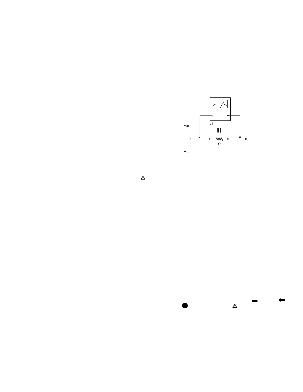
• Alternate check method
Plug the AC line cord directly into the AC outlet. Use an
AC voltmeter having, 1,000Ω per volt or more sensitivity
in the following manner. Connect a 1,500Ω 10W resistor
paralleled by a 0.15µF AC-type capacitor between an ex-
posed metal part and a known good earth ground.
Measure the AC voltage across the resistor with the AC
voltmeter.
Move the resistor connection to each exposed metal
part, particularly any exposed metal part having a return
path to the chassis, and measure the AC voltage across
the resistor. Now, reverse the plug in the AC outlet and
repeat each measurement. Voltage measured any must
not exceed 0.75 V AC (r.m.s.). This corresponds to 0.5
mA AC (r.m.s.).
AC VOLTMETER
(Having 1000
ohms/volts,
or more sensitivity)
0.15 F AC TYPE
Place this
probe on
1500 10W
Good earth ground
1.2 Warning
(1) This equipment has been designed and manufactured to
meet international safety standards.
(2) It is the legal responsibility of the repairer to ensure that
these safety standards are maintained.
(3) Repairs must be made in accordance with the relevant
safety standards.
(4) It is essential that safety critical components are replaced
by approved parts.
(5) If mains voltage selector is provided, check setting for local
voltage.
1.3 Caution
Burrs formed during molding may be left over on some parts
of the chassis.
Therefore, pay attention to such burrs in the case of preforming repair of this system.
1.4 Critical parts for safety
In regard with component parts appearing on the silk-screen
printed side (parts side) of the PWB diagrams, the parts that are
printed over with black such as the resistor ( ), diode ( )
and ICP ( ) or identified by the " " mark nearby are critical
for safety. When replacing them, be sure to use the parts of the
same type and rating as specified by the manufacturer.
(This regulation dose not Except the J and C version)
each exposed
metal part.
(No.YD089)1-3
Page 4
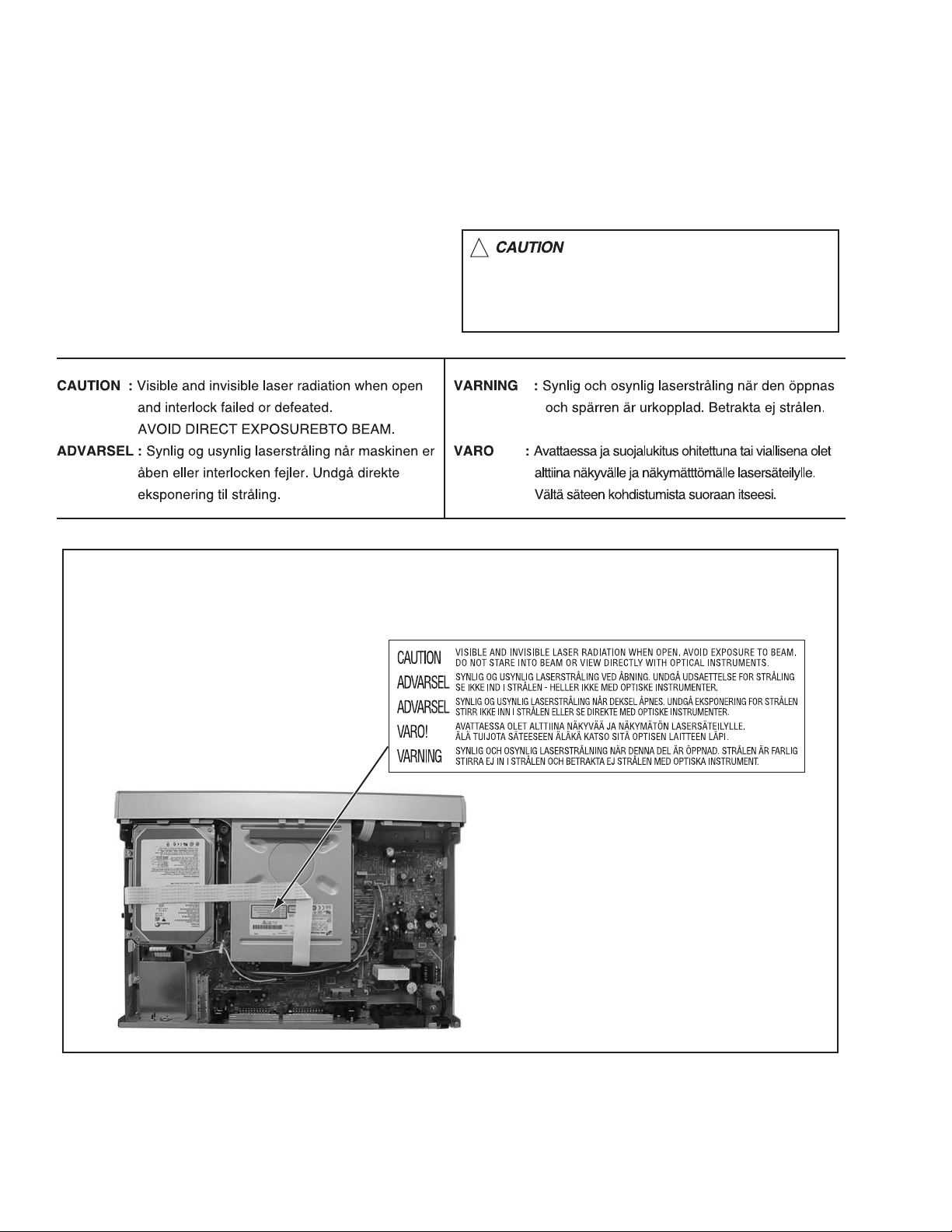
1.5 Important for laser products
!
1.CLASS 1 LASER PRODUCT
2.DANGER : Invisible laser radiation when open and inter
lock failed or defeated. Avoid direct exposure to beam.
3.CAUTION : There are no serviceable parts inside the
Laser Unit. Do not disassemble the Laser Unit. Replace
the complete Laser Unit if it malfunctions.
4.CAUTION : The CD,MD and DVD player uses invisible
laser radiation and is equipped with safety switches which
prevent emission of radiation when the drawer is open and
the safety interlocks have failed or are defeated. It is
dangerous to defeat the safety switches.
5.CAUTION : If safety switches malfunction, the laser is able
to function.
6.CAUTION : Use of controls, adjustments or performance of
procedures other than those specified here in may result in
hazardous radiation exposure.
Please use enough caution not to
see the beam directly or touch it
in case of an adjustment or operation
check.
REPRODUCTION AND POSITION OF LABEL
On mechaism assembly
1-4 (No.YD089)
Page 5
1.6 Hard Disk Drive (HDD) Handling Precautions
The HDD is a precision device for use in reading and writing a large amount of data on or from a disk rotating at a high speed. If it is
not handled carefully, either abnormal operation may result or it may not be possible to read data. The HDD is sensitive to the following
items and special care is required in safeguarding against them when handling an HDD. Also take care in handling a set incorporating
an HDD.
(1) Vibrations and impacts
(2) Static electricity
(3) Rough handling
1.6.1 Handling in transport, etc.
• Be sure to place the HDD in the manufacturer's specified package carton before transport.
• When receiving a package containing an HDD, check that the
package carton is not damaged (such as having holes in the
carton, crushed corners, etc.).
• Do not impact the packaging carton when loading or unloading
HDD
Do not throw or
drop packages.
it.
• It is not permitted to use the inner package carton only for
transporting an HDD.
• Do not stack package cartons one upon another.
Be sure to package and
transport the HDDs correctly.
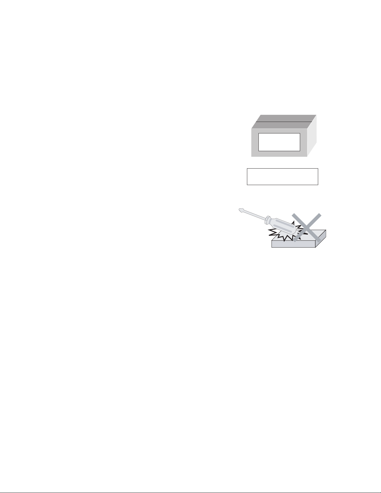
1.6.2 Handling an HDD in the stand-alone status
• When handling an HDD on a hard workbench, place an antistatic mat (rubber sheet) or similar object on the hard surface
(to prevent any impacts occurring between the HDD and
bench).
• Do not stack the HDDs one upon another.
• Do not knock an HDD with a hard object (such as a screwdriver).
• Do not place an HDD on its side panel without using a support
(do not place an HDD in an unstable position).
1.6.3 Handling the installation of an HDD
• Place antistatic mats or similar sheets on all of the surfaces on which work is conducted or when the HDD is transported.
• Do not permit the HDD to knock against the set's brackets.
• When screwing the brackets, be careful not to knock the HDD. When using a power screwdriver, use a low-shock model and arrange
the tightening torque properly.
• When mounting an HDD in a main body, take care not to apply excessive force to the brackets.
(No.YD089)1-5
Page 6

SECTION 2
SPECIFIC SERVICE INSTRUCTIONS
This service manual does not describe SPECIFIC SERVICE INSTRUCTIONS.
1-6 (No.YD089)
Page 7

SECTION 3
TOP COVER
Hook b
DISASSEMBLY
3.1 Main body section
3.1.1 Remove the top cover (See figure 1)
(1) Remove the four screws A attaching the top cover on both
sides of the main body.
(2) Remove the five screws B attaching the top cover on the
back of the main body.
(3) Raise the both sides and lower part of the rear of the top
cover, with opening them slightly in an outward direction.
And the top cover will be removed.
3.1.2 Remove the front panel assembly and HDD (See figure 2, figure 3, figure 4)
• Prior to performing the following procedure, remove the top
cover.
• There is no need to remove the drive unit.
(1) Remove the four screws C attaching the HDD.
(2) Disconnect the card wire from connector CN2201
digital board.
(3) Disconnect the socket wire from connector CN5304
main board.
(4) Disconnect the card wire from connector on the HDD.
(5) Disconnect the card wire from connector CN4001
main board.
(6) Disconnect the card wires from connector CN7002
CN7003 on the display board.
(7) Remove the two screws D attaching the front panel assem-
bly.
(8) Hooks a and b are removed respectively, and the front
panel assembly is removed.
CN2201
HDD
C
Main board
on the
on the
on the
,
A x 2
CN4001
A x 2
TOP COVER
TOP COVER
B
Fig.1
Main board
Fig.3
B
B
B
B
CN7003CN7002
D
Hook a
C
C
Connector
Front panel assembly
D
Hook b
C
Fig.2
CN5304
Hook a
Fig.4
(No.YD089)1-7
Page 8

3.1.3 Remove the drive unit (See figure 5)
• Prior to performing the following procedure, remove the top
cover.
• There is no need to remove the front panel assembly.
(1) Disconnect the socket wire from connector CN5301 on the
main board.
(2) Disconnect the card wire from connector CN2201
on the
digital board.
(3) Remove the four screws E attaching the drive unit.
E
Drive unit
CN5301
E
CN2201
3.1.4 Remove the HDMI board and digital board (See figure 6, figure 7)
• Prior to performing the following procedure, remove the top
cover and HDD.
(1) Disconnect the socket wire from connector CN2404
on the
HDMI board.
Digital board
CN2401
(2) Remove the three screws F attaching the HDMI board.
(3) Remove the two screws G (G1, G2) attaching the HDMI
board from rear side.
(4) Disconnect the connector from CN2401
on the HDMI board
from digital board.
(5) Disconnect the card wire from connector CN1103
on the
digital board.
(6) Disconnect the socket wire from connector CN1101,
CN1102
, CN1801 on the digital board.
(7) Remove the four screws H attaching the digital board.
H
F
F
CN2404
HDMI board
CN1103
CN1801
HH
F
Main board
E
CN1101
H
Rear panel
E
Fig.5
CN1102
Fig.6
1-8 (No.YD089)
G2G1
Torque
Please note tightening too much.
G1 --- 0.784 N-m +- 0.078N-m ( 8.0 kgf-cm +- 0.8 kgf-cm )
G2 --- 0.25 N-m ~ 0.35N-m ( 2.6 kgf-cm ~ 3.6 kgf-cm )
Fig.7
Page 9

3.1.5 Remove the main board (See figure 8, figure 9)
• Prior to performing the following procedure, remove the top
cover, drive unit, HDD.
(1) Disconnect the card wire from connector CN4103
on the main board.
(2) Disconnect the socket wire from connector CN1101
CN1102
(3) Disconnect the socket wire from connector CN3004,
CN5303
(4) Disconnect the power cord from connector CN5001
main board.
(5) Remove the six screws I attaching the main board.
(6) Remove the seven screws J attaching the rear panel with
main board.
(7) Remove the one screw K attaching the tuner.
, CN7001 on the digital board and display board.
on the main board.
, CN4001
on the
CN1101
CN1102
CN4001
,
Display board
I
CN7001
CN3004
I
I
I
I
3.1.6 Remove the display board (See figure 10)
• Prior to performing the following procedure, remove the top
cover, drive unit, HDD, front panel assembly.
(1) Disconnect the socket wire from connector CN7001 on the
display board.
(2) Remove the two screws L attaching the display board.
Digital board
CN4103
L
I
CN7001
Main board
Fig.8
Fig.9
Display board
Fig.10
CN5303
JJ Rear panelK
CN5001
L
(No.YD089)1-9
Page 10

SECTION 4
ADJUSTMENT
4.1 Timer clock adjustment (for only ver.E,ER)
If an error comes to arise for a clock, the following procedure will adjust.
Signal (A1) No signal
Mode (B) EE
Equipment (C) Frequency counter
Measuring point (D1)
Adjustment part (F) C3033 (TIMER CLOCK)
Specified value (G1) 1024.008 ±0.001 Hz
(1) Connect the frequency counter to the measuring point (D1).
(2) Connect the short wire between the short point (D2) and Vcc (5V).
(3) Short the leads of capacitor (D3) once in order to reset the microprocessor of the system controller.
(4) Disconnect the short wire between the short point (D2) and Vcc then connect it again.
(5) Adjust the Adjustment part (F) so that the output frequency becomes the specified value (G).
IC3001 pin 29
(D2)
IC3001 pin 83
(D3)
C3021 + and -
(976.5549 ±0.0010 usec)
1-10 (No.YD089)
Page 11

SECTION 5
TROUBLESHOOTING
5.1 JIG Mode
The following remote control units are required to set and cancel JIG mode.
For setting : a remote control unit attached to product.
For cancellation : JIG remote control unit (part number : PTU94023B)
Remote control unit
attached to product
JIG remote control unit
JIG remote control unit
[Data transmission]
Set the data code,
and then press the
" " button.
3
Custom code
43:A Code
53:B Code
6F:C Code
7F:D Code
Data code
Initial mode
When the main body is set to JIG mode and when the main body is under JIG mode, the remote control unit attached to product operates only in "Remote Control Code 1". Since main body is in "Remote Control Code 3" when it is shipped and just after its batteries
are changed, "Remote Control Code 3" needs to be changed to "Remote Control Code 1."
< Changing Remote Control Code >
(1) The switch of remote controller is switched to the DVD side.
(2) Press the numeric button "1" of the remote control unit while pressing the "SET UP" button of the remote control unit. Then,
press the "ENTER" button, and then release the "SET UP" button.
(3) Press the "PLAY" button of the main body for five seconds or longer while the main body is in stand-by mode, and a current
remote control code of the main body is displayed in FL indicator of the main body.
(4) While keeping the state of (3), press the "STOP" button of the remote control unit toward the main body.
(5) The code that was set by the remote control unit blinks for 5 seconds, before the code is set to the main body. When the FL
indicator changes to “DVD 1”, it shows that the Remote Control Code has been changed to “1”.
(1)
(2)b
(2)c
(4)
(2)a
"(2) a-c" shows the order of pressing the buttons.
HDD DVD
STANDBY/ON
RAM/RW
DVD 1
(3)(3),(5)
NAVIGATION
GUIDE
PUSH-OPEN
PR
PR
ENTER
(No.YD089)1-11
Page 12

5.1.1 Setting JIG mode
To display SYSTEM INFO or to update firmware, the main body needs to be set to JIG mode.
(1) Turn the main body ON.
(2) Press the buttons of the remote control unit attached to product in the following order : "SET UP" → "2" → "8" → "ENTER"
(3) When a colon ":" between "hour" and "minute" of a clock in FL indicator blink, it means that the main body has been set to JIG
mode properly.
[ Example ]
Not in JIG mode In JIG mode
15 : 07
15 07
A colon blinks.
(4) Turn the main body OFF, and then turn it ON again.
*Once the main body is set to JIG mode, the JIG mode cannot be cancelled even if the power cord is pulled out from the wall
socket.
"(2) a-d" shows the order of pressing the buttons.
(2)b
(2)c
(2)d
(3)(1),(4)
PR
ENTER
PUSH-OPEN
PR
(2)a
STANDBY/ON
HDD DVD
RAM/RW
15 : 07
NAVIGATION
GUIDE
5.1.2 Canceling JIG mode
(1) Transmit "43-9D" to the main body by using JIG remote control unit.(Please end a setting menu pushing “SET UP” button of the
remote control unit appended to the commodity beforehand when a setting menu is displayed.)
(2) A colon ":" between "hour" and "minute" of a clock in FL indicator light.
(3) Turn the main body OFF, and then turn it ON again.
NOTE:
After repair work, be sure to cancel JIG mode. Before returning product to a user, confirm that a colon ":" between "hour" and
"minute" of a clock in FL indicator light.
1-12 (No.YD089)
Page 13

5.2 Displaying SYSTEM INFO
In the SYSTEM INFO there is information including Firmware Versions of the main body and the drive unit.
(1) Set the main body to JIG mode.
(2) Transmit "43-8B" to the main body by using JIG remote control unit.(Please end a setting menu pushing “SET UP” button of the
remote control unit appended to the commodity beforehand when a setting menu is displayed.)
(3) SYSTEM INFO menu is displayed in the television screen.
(4) To move cursor in SYSTEM INFO, use the "", "", "", and "" buttons of a main body or remote control unit attached to
product.
The example of a display < Version Info 1 >
System Info
Version Info 1
Version Info 2 NAVI Info Initialize
Application Software Version
Boot Loader Software Version
DVD Drive Firmware Version
Regiaon
CPRM Key DownLoad
HDMI CPU Version
OK
EXIT
SELECT
SELECT WITH [ ] THEN PRESS [ENTER]
PRESS [ "8b" ] TO EXIT
0.58
1.2/276
P020
2
Done
16
Firmware version of the main body.
When the firmware of the main body is updated,
this part is changed.
Firmware version of the drive unit.
When the firmware of the main body is updated,
this part is changed.
NOTE :
Items other than the ones described above are not used in service work.
(5) To quit the SYSTEM INFO menu, transmit "43-8B" to the main body by using JIG remote control unit.
(6) Cancel JIG mode.
5.2.1 Displaying the firmware version of the main body in the user mode
The version information of the main body firmware can be displayed in the normal mode (user mode) without using the Jig mode.
The version can be checked by the user operation when it is required to check the version when there are failure inquiries from the
users.
(1) Turn the power of the main body ON.
(2) Press the “SET UP” button of the supplied remote control unit to display the setting menu screen.
(3) Move the arrow to the “INITIAL SET UP” tab, keep pressing the “STOP” button of the main body for 10 seconds in that condition.
(4) The screen changes to the display shown in the below diagram, and the firmware version of the main body is indicated.
DVD VIDEO SET UP
HDD/DVD SET UP
TUNER SET CLOCK SET
FUNCTION SET UP
INITIAL SET UP
VERSION : 0.58
O K
(No.YD089)1-13
Page 14

5.3 Updating the firmware of the main body
• Firmware update disc supports CD-R media.
• When firmware update is necessary, information is available from the website of DIGITAL VIDEO STORAGE CATEGORY, CS
group.
5.3.1 Creating an update disc
Please check the details of the update disc creation method with JS-NET.
(1) Down load the update file from JS-NET.
(2) Write the update file into CD-R. Pay attention in the following points when writing the update disc.
• Make sure to write in "Disc at Once".
• Set the file compatibility to "ISO9660 format". (ROMEO, JOLIET are disapproved.)
If the writing method is not correct, the update results in an error.
5.3.2 Update procedure
• There are two methods of updating firmware, using JIG mode <method 1> or not using JIG mode(User update mode) <method 2>.
Both methods can be used to update the firmware.
<Method 1>
(1) Set to the JIG mode.
(2) Switch the main body to “DVD”, load the update disc on the tray, and then close the tray.
(3) When the disc reading operation is completed, transmit “43-70” with the JIG remote control unit.
If the update disc is not correct, FL indicator displays “ERROR” after transmitting “43-70”. Transmit “43-70” once and make
the FL indicator to normal display, and then reload the disc then transmit “43-70” again.
(4) “UPDATE” is displayed in the FL indicator, and the FL indicator changes to “FW UPDATE” afterwards. It takes approx. 2 min-
utes for the change.
(5) Remove the disc as the tray is ejected, and then transmit “43-70” with the JIG remote control unit. Then the FL indicator chang-
es from “UPDATE” to the normal display.
(6) Close the tray and turn the power of the main body OFF. Pull out the power cord from the wall socket, and then plug the power
cord into the wall socket again.
(7) “PLEASE” and “WAIT” blink alternately and it is displayed in FL indicator. Then, turn the main body ON.
(8) Check the version of the firmware.
(9) Cancel the JIG mode.
<Method 2>
(1) Turn the power ON. Load the update disc on the tray and close the tray.
(2) Switch the main body to “DVD”.
(3) When the disc reading operation is completed, check “CD” or “DVD-RAM” display in the FL indicator.
(4) When keep pressing the “STOP” button for 5 seconds, “UPDATE” is displayed in the FL indicator and the update is started.
(5) In approx. 2 minutes the tray is ejected, remove the disc. The tray is automatically closed.
(6) Reset operation is carried out automatically, and it becomes standby status.
(7) Check the version of the firmware.
1-14 (No.YD089)
Page 15

5.4 Updating the firmware of the drive unit
• Firmware update disc supports only DVD-RAM media.
• When firmware update is necessary, written discs are distributed by DIGITAL VIDEO STORAGE CATEGORY, CS group.
(1) Turn the main body ON, and switch the main body to “DVD”.
(2) Load the update DVD-RAM disc on the tray and close the tray.
(3) “READING” is displayed in the FL indicator and the update is started.
(4) In a short while “READING” in the FL indicator disappears, open the tray to remove the disc and close the tray.
(5) Turn the power OFF and pull out the power code from the wall socket, then plug the power cord into the wall socket again.
(6) Set to the JIG mode and check the firmware version of the drive.
5.5 Taking out a disc
<Method 1 >
There is a forced tray eject mode with electrical operation.
(1) Right after plugging in the power code (while “PLEASE” and “WAIT” blink alternately and it is displayed), keep pressing the
OPEN/CLOSE button of the main body.
(2) Remove the disc as the tray is ejected in a short while.
(3) The tray closes automatically at about five seconds.
<Method 2 >
When the disc cannot be removed by operating above <Method 1 >, open the front door of the main body manually and directly
press the EJECT button located in the lower right of the drive unit.
<Method 3 >
When neither <Method 1> nor <Method 2> can remove the disc, the tray can be ejected mechanically without turning the power on.
(1) Open the front door of the main body manually.
(2) Insert a fine wire (e.g. a straightened paper clip) into the hole in the lower part of the tray of the drive unit.
(3) As the tray ejects a little, pull out the tray manually.
Front door Hole EJECT Button
5.6 Exchanging the fitting
As the fitting that comes with the service drive unit cannot be used, make sure to attach a service fitting when the drive unit is exchanged. The fitting that is removed from the old drive unit can be attached to the new drive unit.
The fitting can be removed by pulling upwards while opening out the lower part of the fitting outwards.
Tray
Fitting
(No.YD089)1-15
Page 16

5.7 Initialization to the factory shipment state
When the initialization is operated, internal information changes as follows. It is essential to obtain the client’s permission before the
operation.
• All DVD library is all deleted.
• All the DVD initial settings go back to the initial status.
(1) Set to the JIG mode.
(2) Transmit “43-6F” with the JIG remote control unit.
(3) FL indicator displays “FACTORY”, and changes to “CHECK OK” after blinking for a short while.
(4) Pull out the power code from the wall socket.
(5) The JIG mode is forced to cancel at the same time with the initialization, check whether the JIG mode is canceled by plugging
the power code into the wall socket again. (The colon “:” in time display should be continuously ON, not blinking.)
If the JIG mode is not canceled, transmit “43-9D” with JIG remote control unit to cancel the JIG mode.
5.8 Setting after the drive unit replacement
When the drive unit is replaced, it is necessary to set a region code. Service drive units for replacement are not set for any region
code, and they are in an indefinite condition.
Make sure to set region code after attaching the drive unit to the main body.
Without the setting of the region code, discs that have regions cannot be played back.
5.8.1 Creating a region setting disc.
Please check the details of the region setting disc creation method by JS-NET.
(1) Download the region setting file from JS-NET.
(2) Write the region setting file into CD-R. Pay attention in the following points when writing the file into CD-R.
• Make sure to write in “Disc at Once”.
• Set the file compatibility to “ISO9660 format”. (ROMEO, JOLIET are disapproved).
If the writing method is not correct, the normal setting cannot be performed.
5.8.2 Setting the region
(1) Set for the JIG mode, and switch the main body to “DVD”.
(2) Load the region setting disc on the tray, and then close the tray.
(3) When the disc reading operation is completed, transmit “43-70” with the JIG remote control unit.
(4) FL indicator changes to “UPDATE”. Remove the disc as the tray will open for a few seconds.
(5) Then, check whether the FL indicator is “REGION 2”, and then close the tray.
(6) Turn the power OFF, and pull out the power code, and then plug the power code in again.
(7) Cancel the JIG mode.
5.9 When it is displayed in FDP, “RESETTING”
When the following operations are carried out, “RESETTING” is displayed in the FDP of the main body.
(1) When the “POWER” button and the “STOP” button of the main body are pressed at the same time
(2) When the code “9B” is transmitted to the main body by using JIG remote control unit in JIG mode.
(3) When transmission failure occurs between the main CPU and the DVD host CPU due to defect.
If “RESETTING” is displayed in the FDP after the power code is plugged into the outlet, check the followings.
• The peripheral circuitry of each microcomputer
• Whether the wire between the DVD drive and the board is properly connected
• Whether the wire between the main board and the digital board is properly connected
1-16 (No.YD089)
Page 17

(No.YD089)1-17
Page 18

Victor Company of Japan, Limited
DIGITAL VIDEO STORAGE CATEGORY 12, 3-chome, Moriya-cho, kanagawa-ku, Yokohama, kanagawa-prefecture, 221-8528, Japan
(No.YD089)
Printed in Japan
VPT
 Loading...