

Page 1
Operating Instructions
51105427
DFG/TFG 316s-320s
G
04.08 -
07.08
Page 2

0108.GB
Foreword
The present ORIGINAL OPERATING INSTRUCTIONS are designed to provide
sufficient instruction for the safe operation of the industrial truck. The information is
provided clearly and concisely. The chapters are arranged by letter. Each chapter
starts with page 1. The page identification consists of a chapter letter and a page
number.
For example: Page B 2 is the second page in chapter B.
The operating instructions detail different truck models. When operating and servicing
the truck, make sure that the instructions apply to your truck model.
Safety instructions and important explanations are indicated by the following
graphics:
F
Used before safety instructions which must be observed to avoid danger to
personnel.
M
Used before notices which must be observed to avoid material damage.
Z
Used before notices and explanations.
t Used to indicate standard equipment.
o Used to indicate optional equipment.
Our trucks are subject to ongoing development. Jungheinrich reserves the right to
alter the design, equipment and technical features of the truck. No guarantee of
particular features of the truck should therefore be inferred from the present operating
instructions.
Copyright
Copyright of these operating instructions remains with JUNGHEINRICH AG.
Jungheinrich Aktiengesellschaft
Am Stadtrand 35
22047 Hamburg - GERMANY
Telephone: +49 (0) 40/6948-0
www.jungheinrich.com
Page 3

0108.GB
Page 4

I 1
0708.GB
Table of contents
A Correct Use and Application
B Truck Description
1 Application ........................................................................................... B 1
2 Assemblies and Functional Description .............................................. B 2
2.1 Truck ................................................................................................... B 3
2.2 Load handler ....................................................................................... B 4
3 Standard Version Specifications ......................................................... B 5
3.1 DFG/TFG 316s/320s Specifications .................................................... B 8
4 Identification points and data plates .................................................... B 11
4.1 Truck data plate .................................................................................. B 12
4.2 Truck load chart .................................................................................. B 13
4.3 Attachment load chart ......................................................................... B 14
C Transport and Commissioning
1 Transport ............................................................................................. C 1
2 Lifting by crane .................................................................................... C 1
3 Securing the truck during transport ..................................................... C 2
4 Using the truck for the first time .......................................................... C 3
5 Operating the truck without its own drive system ................................ C 3
D Fuelling the Truck
1 Safety regulations for handling diesel fuel and LPG ........................... D 1
2 Filling with diesel ................................................................................. D 2
3 Replace the LPG bottle ....................................................................... D 3
E Operation
1 Safety Regulations for the Operation of Forklift Trucks ...................... E 1
2 Controls and Displays ......................................................................... E 3
3 Operating the lift and tilt mechanisms (o) .......................................... E 8
4 Twin Pedal Operation (o) ................................................................... E 9
5 Tests and tasks to be performed before starting the truck .................. E 14
6 Starting up the truck ............................................................................ E 19
6.1 Adjusting the driver’s seat ................................................................... E 20
6.2 Adjusting the steering column ............................................................. E 21
6.3 Seat belt .............................................................................................. E 21
7 Starting the truck ................................................................................. E 22
7.1 Starting procedure for the TFG ........................................................... E 23
7.2 Starting procedure for the DFG ........................................................... E 24
7.3 Operating Error Displays ..................................................................... E 26
7.4 Switching off the engine ...................................................................... E 26
Page 5

0708.GB
I 2
8 Industrial Truck Operation ................................................................... E 27
8.1 Safety regulations for truck operation ................................................. E 27
9 Travel .................................................................................................. E 29
9.1 Steering ............................................................................................... E 31
9.2 Brakes ................................................................................................. E 31
10 Mast and Attachment Operation ......................................................... E 33
10.1 Controlling the speed of the lifting device ........................................... E 35
10.2 Lifting, transporting and depositing load units ..................................... E 36
11 Transporting loads .............................................................................. E 39
12 Hazardous situations ........................................................................... E 41
12.1 Parking the truck safely ....................................................................... E 42
13 Engine bonnet and service covers ...................................................... E 43
13.1 Service covers ..................................................................................... E 44
13.2 Towing the truck .................................................................................. E 45
13.3 Towing trailers ..................................................................................... E 45
14 Troubleshooting .................................................................................. E 46
F Truck Maintenance
1 Operational Safety and Environmental Protection .............................. F 1
2 Maintenance Safety Regulations ........................................................ F 1
3 Servicing and Inspection ..................................................................... F 3
4 DFG/TFG maintenance checklist ........................................................ F 4
5 DFG maintenance checklist ................................................................ F 6
6 TFG maintenance checklist ................................................................. F 7
7 Coolant specification ........................................................................... F 8
8 Consumables ...................................................................................... F 9
9 DFG fuel specifications ....................................................................... F 9
10 Lubrication chart .................................................................................. F 10
10.1 Lubrication chart - DFG/TFG ............................................................... F 11
11 Maintenance and repairs ..................................................................... F 12
11.1 Preparing the truck for maintenance and repairs ................................ F 12
11.2 Starting aid .......................................................................................... F 12
11.3 Servicing the engine - TFG 316s/320s ................................................ F 13
11.4 Engine servicing - DFG 316s/320s ..................................................... F 16
11.5 Checking the coolant concentration .................................................... F 19
11.6 Filling the cooling circuit ...................................................................... F 19
11.7 Cleaning/replacing the air filter cartridge ............................................. F 20
11.8 Checking the wheel attachment and air pressure ............................... F 21
11.9 Hydraulic system ................................................................................. F 22
11.10 Electrical system ................................................................................. F 23
11.11 Relay layout ........................................................................................ F 26
12 Exhaust system ................................................................................... F 27
13 Restoring the truck to service after cleaning or repairs ....................... F 27
14 Decommissioning the industrial truck .................................................. F 27
14.1 Prior to decommissioning .................................................................... F 27
14.2 During decommissioning: .................................................................... F 28
Page 6

I 3
0708.GB
14.3 Returning the truck to operation after decommissioning ..................... F 28
15 Periodic safety checks and after unusual events ................................ F 29
16 Final de-commissioning, disposal ....................................................... F 29
17 HUSS FS - MK Series Diesel Particle Filter Operating Instructions .... F 30
17.1 Important General Instructions ............................................................ F 30
17.2 Important safety instructions ............................................................... F 30
17.3 Functional description ......................................................................... F 31
17.4 HUSS Control Operation ..................................................................... F 32
17.5 HUSS Control Operating Instructions ................................................. F 33
17.6 Regeneration ....................................................................................... F 34
17.7 Maintenance ........................................................................................ F 37
Page 7

0708.GB
I 4
Page 8

A 1
03.08.GB
A Correct Use and Application
Z
The “Guidelines for the Correct Use and Application of Industrial Trucks” (VDMA) are
supplied with the truck. The guidelines form part of these operating instructions and
must be observed. National regulations apply in full.
It must be used, operated and serviced in accordance with the present instructions.
Any other type of use is beyond the scope of application and can result in damage to
personnel, the industrial truck or property. In particular, avoid overloading the truck
with loads which are too heavy or placed on one side. The data plate attached to the
truck or the load chart are binding for the maximum load capacity. The industrial truck
must not be used in fire or explosion endangered areas, or areas threatened by
corrosion or excessive dust.
Proprietor responsibilities: For the purposes of the present operator manual the
“proprietor” is defined as any natural or legal person who either uses the industrial
truck himself, or on whose behalf it is used. In special cases (e.g. leasing or renting)
the proprietor is considered the person who, in accordance with existing contractual
agreements between the owner and user of the industrial truck, is charged with
operational duties.
The proprietor must ensure that the industrial truck is used only for the purpose it is
intended for and that danger to life and limb of the user and third parties are excluded.
Furthermore, accident prevention regulations, safety regulations and operating,
servicing and repair guidelines must be followed. The owner must ensure that all
users have read and understood these operating instructions.
M
Failure to comply with the operating instructions shall invalidate the warranty. The
same applies if improper work is carried out on the truck by the customer or third
parties without the permission of the manufacturer’s customer service department.
Attaching accessories: The mounting or installation of additional equipment which
affects or enhances the performance of the industrial truck requires the written
permission of the manufacturer. In some cases, local authority approval shall be
required.
Approval of the local authorities however does not constitute the manufacturer’s
approval.
Towing trailers
Z
see Chapter E, Section 13.3.
Page 9

03.08.GB
A 2
Page 10
B 1
04.08.GB
B Truck Description
1 Application
The DFG/TFG series trucks are 4-wheel sit-down IC engine forklifts. The DFG series
are diesel engine trucks, while the TFG series are fitted with a petrol engine for LPG
operation.
The DFG/TFG 316-320s is equipped with a hydrostatic drive system. The IC engine
drives a high pressure pump for the hydraulic functions and two hydraulic motors to
drive wheels.
Truck models and maximum capacity.
*) The load charts attached to the truck are binding in terms of capacity
Model Capacity (kg)*) Wheel base (mm)
DFG/TFG 316s 1600 1400
DFG/TFG 320s 2000 1400
Page 11

04.08.GB
B 2
2 Assemblies and Functional Description
Item Description Item Description
1 t Lift cylinder 8 t Trailer coupling
2 t Load chain 9 t Counterweight
3 t Mast 10 t Steering axle
4 t Dashboard 11 t Engine cover
5 t Steering column 12 t Hydrostatic drive axle
6 t Overhead guard 13 t Fork carriage
7 t Driver's seat 14 t Fork
Page 12

B 3
04.08.GB
2.1 Truck
Chassis/Superstructure: A rigid chassis which protects the units and controls,
provides the truck with maximum static safety. The operator position is articulating,
which cushions vibrations and noise.
Maintenance and servicing are made easy through the wide opening cover and the
two side panels of the engine housing (11). The hydraulic oil reservoir is integrated
on the right-hand side and the fuel tank for the DFG series on the opposite side in the
chassis. The LPG bottle for the TFG series is secured to a bracket on the
counterbalance weight (9). The exhaust system and exhaust pipe prevents exhaust
from entering the operator position and reduces exhaust noise.
Operator position: Non-slip steps and a handle on the posts of the overhead guard
provide easy entry and exit. The driver is protected by the overhead guard (6). On the
driver’s seat (7) the seat cushioning and the seat position are adjustable, while the
steering wheel tilt can be set on the steering column (5). Easy operation through
ergonomically arranged controls and a practically vibration-proof cab mean that the
driver is only subjected to minimum stress. The control and warning displays on the
dashboard (4) enable the system to be monitored during operation, thereby ensuring
a very high level of safety.
Engine: Silent, water-cooled engines featuring high performance and low
consumption. In the DFG series diesel engines are used with very clean fuel
combustion under all operating conditions and soot levels below the visibility level.
For the TFG series petrol engines are used with very low residual exhaust levels.
Drive: Both drive wheels are powered by individual hydraulic motors which in turn are
driven by a hydraulic pump. Forward/reverse or neutral can be set with the travel lever
on the control panel.
Steering: Hydrostatic steering with a steering cylinder integrated in the steering axle
(10). The steering axle is fully floating in the chassis to ensure excellent grip even on
non-level surfaces.
Brakes: The truck brakes to a halt via the hydraulic motors, keeping energy
consumption to a minimum. The parking brake is an automatic multi-plate brake.
Hydraulic system: All operations can be performed sensitively, proportionally and
simultaneously.
Hydraulic functions are controlled by the control lever through a multiple control valve.
Page 13

04.08.GB
B 4
Electrical system: 12 volt system with starter battery and AC generator with
integrated controller. A repeat start block prevents incorrect operation during start-up
and a safety switch ensures the engine can only start when the travel direction lever
is in neutral. For diesel motors, a rapid pre-heat system is installed, LPG motors have
a non-contact electronic ignition system for rapid and trouble-free engine starting.
The ignition / start switch is used to stop the engine.
2.2 Load handler
Mast: The aim is to optimise visibility. The maximum strength steel section are
narrow, allowing for good fork visibility in particular with the three-stage mast. The
same standard has been achieved for the fork carriage. The mast and the fork
carriage run on permanently-lubricated and hence maintenance-free angled castors.
Attachments: The trucks can be optionally fitted with mechanical and hydraulic
attachments.
Page 14
B 5
04.08.GB
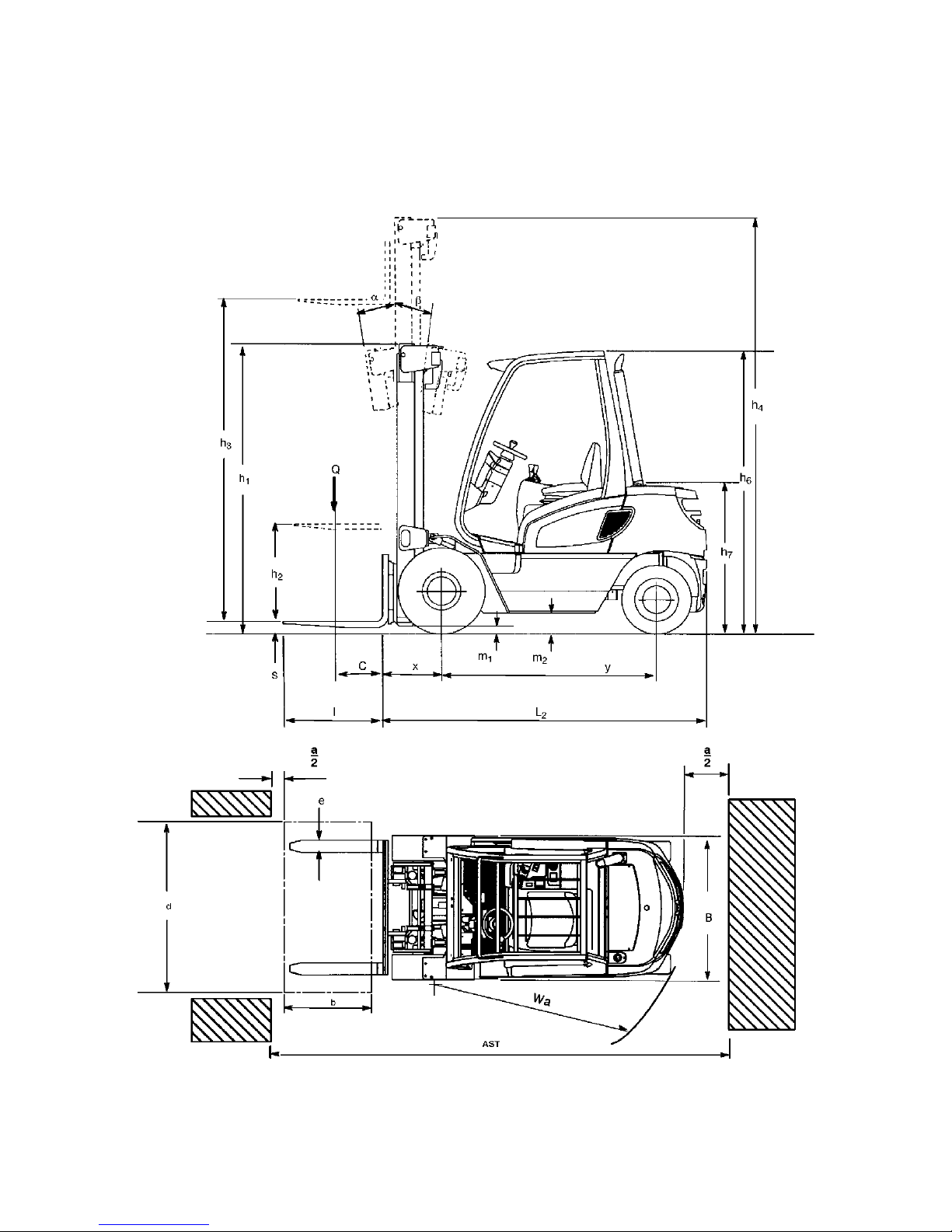
3 Standard Version Specifications
Z
Technical specification details in accordance with VDI 2198. Technical modifications
and additions reserved.
Page 15

04.08.GB
B 6
DFG 316s/320s Specification Sheet
No. Description Code
(Unit)
AH-J
Specification
1 Manufacturer Jungheinrich Jungheinrich
1.2 Model DFG 316s DFG 320s
1.3 Drive system: electric, diesel, petrol, LPG, other Diesel Diesel
1.4 Steering: manual, pedestrian truck, stand-up, sit-down,
order picker
Sit-down Sit-down
1.5 Capacity Q(t) 1.6 2.0
1.6 Load centre of gravity c(mm) 500 500
1.8 Load distance x(mm) 395 395
1.9 Wheel base y(mm) 1400 1400
Weight
2:1 Weight - unladen (kg) 3020 3270
2.2 Axle load, laden, front/rear (kg) 4000/620 4600/670
2.3 Axle load, unladen, front/rear (kg) 1320/1700 1240/2030
Longitudinal stability 1.66 1.59
Tyres/chassis
3.1 Tyre type: elastic, super elastic, pneumatic Polyurethane tyres
SE(L)/SE(L) SE(L)/SE(L)
3.2 Tyre size: Front 6.50-10 (14PR) 6.50-10 (14PR)
3.3 Tyre size: rear 18x7-8 (16PR) 18x7-8 (16PR)
3.5 No. of wheels front/rear (x = mechanical pull) 2x/2 2x/2
3.6 Track width, front b
10
(mm) 895 895
3.7 Track width, rear b
11
(mm) 870 (offset) 870 (offset)
Dimensions
4.1 Mast/chassis tilt, front/rear Degrees 7/10 7/10
4.2 Lowered mast height h
1
(mm) 2080 2080
4.3 Free lift h
2
(mm) 100 100
4.4 Lift height h
3
(mm) 3090 3090
4.5 Extended mast height h
4
(mm) 3670 3670
4.7 Overhead guard height (cabin) h
6
(mm) 2130 2130
4.8 Seat height / headroom (SIP 100 mm) h
7
(mm) 1005/1065 1005/1065
4.12 Hitch height h
10
(mm) 375/545 375/545
4.19 Overall length l
1
(mm) 3245 3300
4.20 Length to fork surface l
2
(mm) 2245 2300
4.21 Overall width b
1/b2
(mm) 1070 1070
4.22 Fork dimensions s/e/l(mm) 40/100/1000 40/100/1000
4.23 Carriage DIN 15173, ISO 2328, class/type A,B ISO 2A ISO 2A
4.24 Fork carriage width / outer forks b
3
(mm) 1000/849 1000/849
4.31 Ground clearance laden below mast m
1
(mm) 115 115
4.32 Ground clearance (centre wheelbase) m
2
(mm) 135 135
4.33 Working aisle width for pallets 1000 x 1200 traverse Ast(mm) 3570 3615
4.34 Working aisle width for pallets 800 x 1200 lengthwise Ast(mm) 3770 3815
4.35 Turning radius Wa(mm) 1975 2020
Power
5.1 Travel speed w. / w.o. load (km/h) 18.5/19 18.5/19
5.2 Lift speed w. / w.o. load (m/s) 0.61/0.65 0.60/0.65
5.3 Lower speed w. / w.o. load (m/s) 0.55/0.52 0.55/0.53
5.5 Tow force w. / w.o. load (kN) 16.5/8.4 16.2/7.6
5.7 Gradeability w. / w.o. load (%) 36/28 29/22
5.9 Acceleration time w. / w.o. load s 5.1/4.8 5.3/5.0
5.10 Service brake type Hydrostatic Hydrostatic
Engine
7.1 Engine: Manufacturer/Model 404D.22 404D.22
7.2 Engine output in accordance with ISO 1585 (kw) 34.1 34.1
7.3 Speed (rpm) 2400 2400
7.4 Number of cylinders/capacity ( /cm
3
) 4/2216 4/2216
Max. torque Nm/rpm 143/1800 143/1800
Misc.
8.1 Drive type Hydrostatic Hydrostatic
8.2 Hydraulic oil pressure for attachments (bar) 160 160
8.3 Oil flow for attachments l/min 45 45
Page 16

B 7
04.08.GB
TFG 316s/320s Specification Sheet
No. Description Code
(Unit)
AH-J
Specification
1 Manufacturer Jungheinrich Jungheinrich
1.2 Model TFG 316s TFG 320s
1.3 Drive system: electric, diesel, petrol, LPG, other LPG LPG
1.4 Steering: manual, pedestrian truck, stand-up, sit-down,
order picker
Sit-down Sit-down
1.5 Capacity Q(t) 1.6 2.0
1.6 Load centre of gravity c(mm) 500 500
1.8 Load distance x(mm) 395 395
1.9 Wheel base y(mm) 1400 1400
Weight
2:1 Weight - unladen (kg) 3000 3250
2.2 Axle load, laden, front/rear (kg) 4030/570 4630/620
2.3 Axle load, unladen, front/rear (kg) 1270/1730 1190/2060
Longitudinal stability 1.69 1.61
Tyres/chassis
3.1 Tyre type: elastic, super elastic, pneumatic Polyurethane tyres
SE(L)/SE(L) SE(L)/SE(L)
3.2 Tyre size: Front 6.50-10 (14PR) 6.50-10 (14PR)
3.3 Tyre size: rear 18x7-8 (16PR) 18x7-8 (16PR)
3.5 No. of wheels front/rear (x = mechanical pull) 2x/2 2x / 2
3.6 Track width, front b10(mm) 895 895
3.7 Track width, rear b11(mm) 870 (offset) 870 (offset)
Dimensions
4.1 Mast/chassis tilt, front/rear Degrees 7/10 7/10
4.2 Lowered mast height h
1
(mm) 2080 2080
4.3 Free lift h
2
(mm) 100 100
4.4 Lift height h
3
(mm) 3090 3090
4.5 Extended mast height h
4
(mm) 3670 3670
4.7 Overhead guard height (cabin) h
6
(mm) 2130 2130
4.8 Seat height / headroom (SIP 100 mm) h
7
(mm) 1005/1065 1005/1065
4.12 Hitch height h
10
(mm) 375/545 375/545
4.19 Overall length l
1
(mm) 3245 3300
4.20 Length to fork surface l
2
(mm) 2245 2300
4.21 Overall width b
1/b2
(mm) 1070 1070
4.22 Fork dimensions s/e/l(mm) 40/100/1000 40/100/1000
4.23 Carriage DIN 15173, ISO 2328, class/type A,B ISO 2A ISO 2A
4.24 Fork carriage width / outer forks b
3
(mm) 1000/849 1000/849
4.31 Ground clearance laden below mast m
1
(mm) 115 115
4.32 Ground clearance (centre wheelbase) m
2
(mm) 135 135
4.33 Working aisle width for pallets 1000 x 1200 traverse Ast(mm) 3570 3615
4.34 »Working aisle width for pallets 800 x 1200 lengthwise Ast(mm) 3770 3815
4.35 Turning radius Wa(mm) 1975 2020
Power
5.1 Travel speed w. / w.o. load (km/h) 18.0/18.5 18.0/18.5
5.2 Lift speed w. / w.o. load (m/s) 0.56/0.65 0.55/0.65
5.3 Lower speed w. / w.o. load (m/s) 0.55/0.52 0.55/0.53
5.5 Tow force w. / w.o. load (kN) 14.6/7.4 14.5/7.1
5.7 Gradeability w. / w.o. load (%) 32/25 28/22
5.9 Acceleration time w. / w.o. load s 4.8/4.6 4.9/4.7
5.10 Service brake type Hydrostatic Hydrostatic
Engine
7.1 Engine: Manufacturer/Model FE 2.0 FE 2.0
7.2 Engine output in accordance with ISO 1585 (kw) 26 26
7.3 Revolutions (rpm) 2400 2400
7.4 Number of cylinders/displacement ( /cm
3
) 4/1998 4/1998
Max. torque Nm/rpm 120/1600 120/1600
Misc.
8.1 Drive type Hydrostatic Hydrostatic
8.2 Hydraulic oil pressure for attachments (bar) 160 160
8.3 Oil flow for attachments l/min 45 45
Page 17

04.08.GB
B 8
3.1 DFG/TFG 316s/320s Specifications
Steering system
Drive axle
Engine - DFG 316s/320s
Engine - TFG 316s/320s
Air filter
Brake system
MODEL Fully hydrostatic
PUMP As for main hydraulic system
NUMBER OF TURNS STOP TO STOP 5
MODEL Radial piston axle
MODEL ESE 02
LUBRICANT CAPACITY N/A
MODEL 404D.22 four cylinder
IGNITION ORDER 1 3 4 2
CONTROL SPEED 2400 rpm (unladen) / 880 rpm (idle)
VALVE CLEARANCE (inlet/outlet) 0.20mm cold
OIL PRESSURE 4.5 bar @ 2300 rpm
OIL CAPACITY 8.9 litres
FUEL TANK 42 litres
COOLANT CAPACITY 9.0 litres
MODEL FE 2.0 four cylinder
IGNITION ORDER 1 3 4 2
CAPACITY 1998cc
CONTROL SPEED 3100 rpm (unladen) / 830 rpm (idle)
OIL PRESSURE 3.0 bar @ 2300 rpm
SPARK PLUG TYPE NGK BPR 2E or DENSO W9EXR-U
SPARK PLUG ELECTRODE DISTANCE 0.80mm
OIL CAPACITY 4.3 litres
FUEL TANK N/A
COOLANT CAPACITY 9.0 litres
MODEL Cyclopac – dry element
MODEL Multiplate brake
PARKING BRAKE Disc works via a hydraulic pressure system
Page 18

B 9
04.08.GB
Wheels and Tyres
Tires
Z
Permissible tyre types: Only use tyres approved by the lift truck manufacturer, if in
doubt contact your local JH service branch.
Noise Emissions
Vibrations
TYRE SIZE See specifications sheet
TYRE PRESSURE
6.50-10
Model Drive axle - bar Steer axle - bar
DFG/TFG 316s/320s 7.75 9.0
23x9-10 DFG/TFG 316s/320s 9.0 9.0
WHEEL NUT TORQUE Model Drive axle - Nm Steer axle - Nm
DFG/TFG 316s/320s 210 176
APPLICATION AREA TYRE SIZE TYPE MODEL
Drive axle 6.50x10 10PR Pneumatic tyres diagonal DFG/TFG 316s/320s
Steer axle 18x7-8 14PR
Drive axle 6.50x10 Full rubber profile DFG/TFG 316s/320s
Steer axle 18x7-8
Drive axle 23x9x10 18PR Pneumatic tyres diagonal DFG/TFG 316s/320s
Steer axle 18x7-8 14PR
Drive axle 23x9x10 Full rubber profile DFG/TFG 316s/320s
Steer axle 18x7-8
NOISE EMISSION LEVEL in accordance with
EN 12053 as harmonised with ISO 4871.
<80 dB(A)
Cyclopac – dry element
The noise emission level is calculated in
accordance with standard procedures and takes
into account the noise level when travelling,
lifting and when idle. The noise level is
measured at the driver’s ear.
WHOLE BODY VIBRATIONS THROUGH
AVERAGE VALUE in accordance with EN 13059
0.57 m/s
The vibration acceleration acting on the body in
the operating position is, in accordance with
standard procedures, the linearly integrated,
weighted acceleration in the vertical direction. It
is calculated when travelling over bumps at
constant speed.
Page 19

04.08.GB
B 10
Electrical system
Hydraulic system
Conditions of use
Z
For constant use below 0°C it is recommended to fill the hydraulic system with frostresistant oil as indicated by the manufacturer. Special equipment and authorisation
are required if the truck is to be used in cold stores or conditions of extreme
temperature or air humidity fluctuations.
SYSTEM 12 volt negative earth
ELECTROMAGNETIC COMPATIBILITY
(EMC)
Within the following limits in accordance with
“Industrial Truck Electromagnetic Compatibility
(9/95)” product standards:
t interference emission (EN 50081-1)
t resistance (EN 50 082-2)
t electrostatic discharge (EN 61000-4-2)
HYDRAULIC PUMP 1PX series
CONTROL VALVE 5000 series
STEER PRESSURE 106 bar
MAIN PRESSURE 215 bar
TANK CAPACITY 46 litres
HYDRAULIC SYSTEM CAPACITY 51 litres
AMBIENT TEMPERATURE
t during operation -15
°C to +40°C
Page 20
B 11
04.08.GB
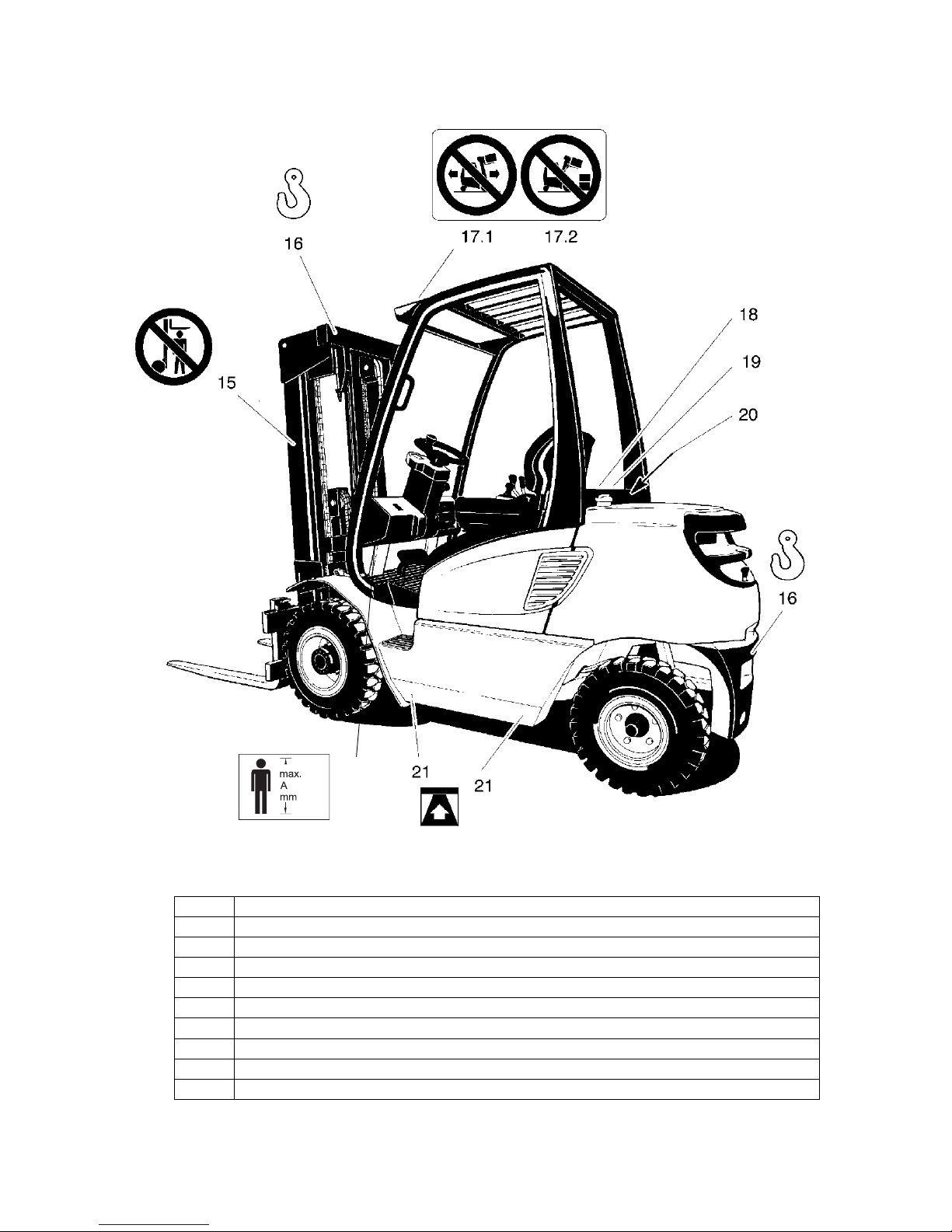
4 Identification points and data plates
Item Description
15 "Do not stand under the load handler" warning
16 Strap points for crane lifting
17.1 “Do not travel with a raised load” warning
17.2 “Do not tilt the mast forward with a raised load” warning
18 Forks, capacity / load centre of gravity / lift height load chart
19 Sideshift, capacity / load centre of gravity / lift height load chart
20 Truck data plate
21 Jack contact points decal
22 “Maximum body size” notice
22
Page 21
04.08.GB
B 12
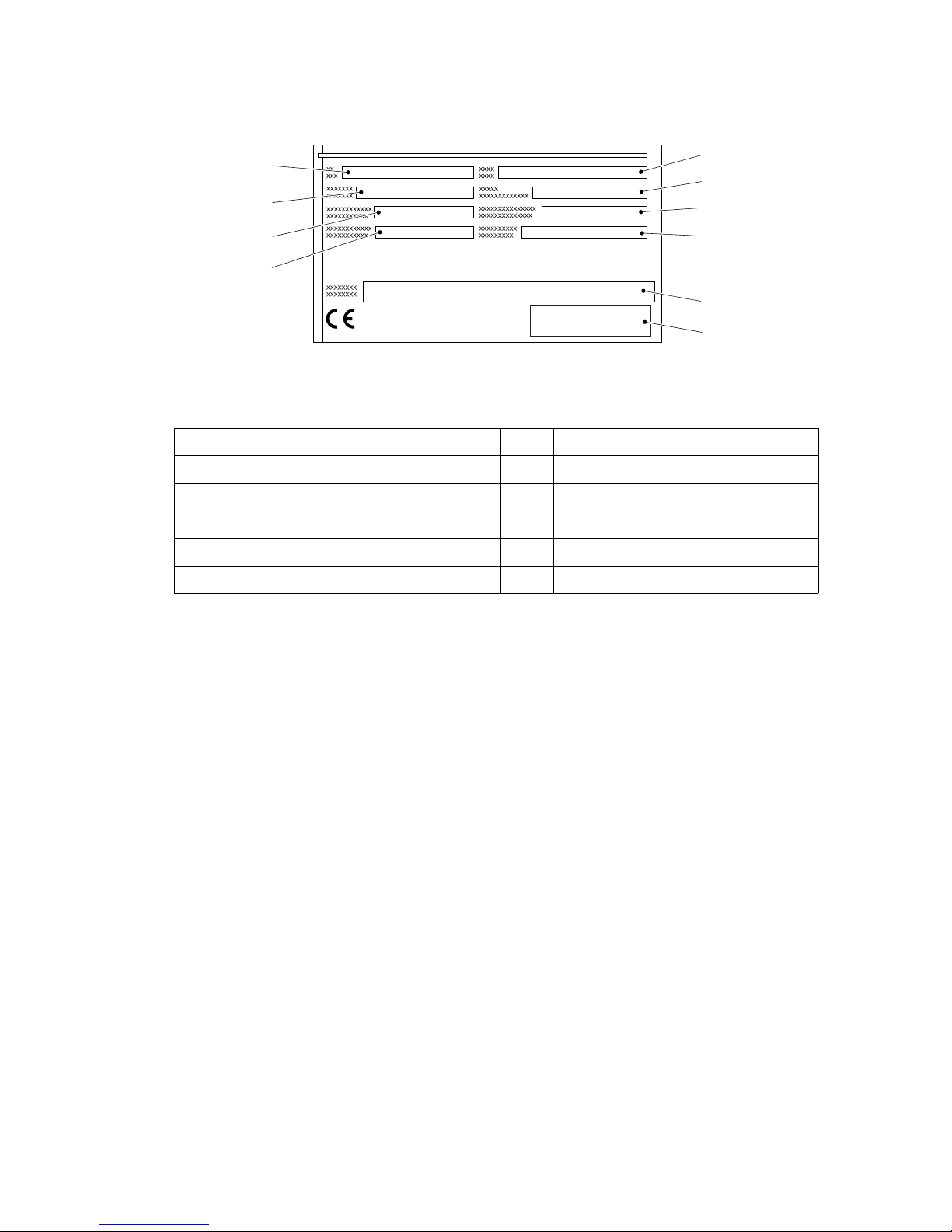
4.1 Truck data plate
Z
For queries regarding the truck or ordering spare parts always quote the truck serial
number (24).
Item Description Item Description
23 Type 28 Manufacturer
24 Serial no. 29 Net weight in kg
25 Rated capacity in kg 30 Load centre of gravity (mm)
26 Rated output (kW) 31 Year of manufacture
27 Manufacturer’s logo 32 Option
23
24
25
26
31
30
27
29
32
28
Page 22
B 13
04.08.GB
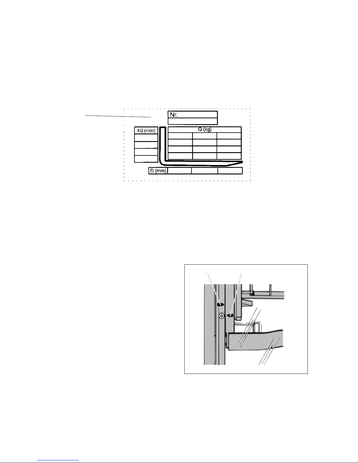
4.2 Truck load chart
The load chart (16) gives the capacity (Q) of the truck in kg with a vertical mast. The
diagram will differ, depending on the height of the mast used. The maximum capacity
is shown as a table with a given load centre of gravity D (in mm) and the required lift
height H (in mm). The truck load chart shows the truck's capacity with new forks (as
supplied). From a fork length of 1300 mm this means a decrease in load. Trucks
supplied without fork tines are given a standard data plate.
The arrow shape markings (38 and 39)
on the inner and outer masts show the
driver when the specified lift limits have
been reached. These arrows are
attached to all masts with a heightdependent capacity rating.
4250
3600
2900
1250 1250
850
500
600 700
1105
1105
850
850
850
600
Example:
16
38 39
Page 23

04.08.GB
B 14
4.3 Attachment load chart
The attachment load chart gives the truck’s capacity Q in combination with the
respective attachment in kg. The serial number specified in the load chart must match
the data plate of the attachment, as the capacity for each truck is specifically indicated
by the manufacturer. It is shown in the same way as the truck’s capacity and can be
determined accordingly.
Z
For loads with a centre of gravity above 500 mm upward, the capacities are reduced
by the difference of the altered centre of gravity.
Page 24
C 1
04.08.GB
C Transport and Commissioning
1 Transport
Transport can be carried out in two different ways, depending on the height of the
mast and the local conditions.
– Vertically, with the mast assembled (for low heights)
– Vertically, with the mast dismantled (for large heights), all hydraulic lines between
the basic truck and the mast separated.
Safety Instructions for Assembly and Commissioning
F
On site assembly of the truck, commissioning and driver instruction may only be
carried out by personnel trained and authorised by the manufacturer.
The hydraulic lines may only be connected to the basic truck / mast interface and the
truck commissioned when the mast has been properly assembled.
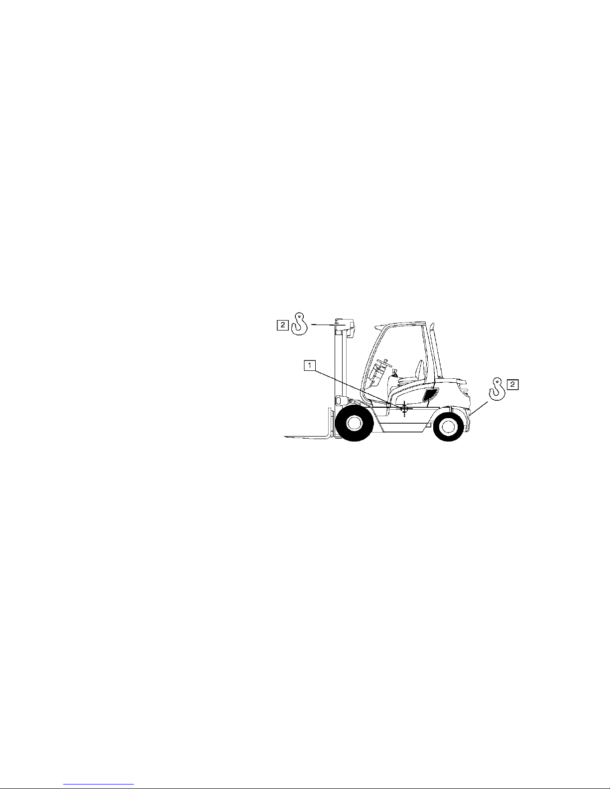
2 Lifting by crane
M
Only use lifting gear with
sufficient capacity (for
transport weight see truck data
plate).
– Parking the truck securely
(see Chapter E).
– Attach the crane slings to the
top cross member of the
mast (1) and the trailer
coupling (2).
M
Only suspend crane belts/chains to the top eye of the counterbalance weight and the
eyes of the upper cross member (mast).
The mast must be tilted back fully.
The crane belt or the chain on the mast must be at least 2m long.
M
Lifting slings should be fastened to the harness in such a way that they do not come
into contact with any attachments or the overhead guard when it is being raised.
Page 25
04.08.GB
C 2
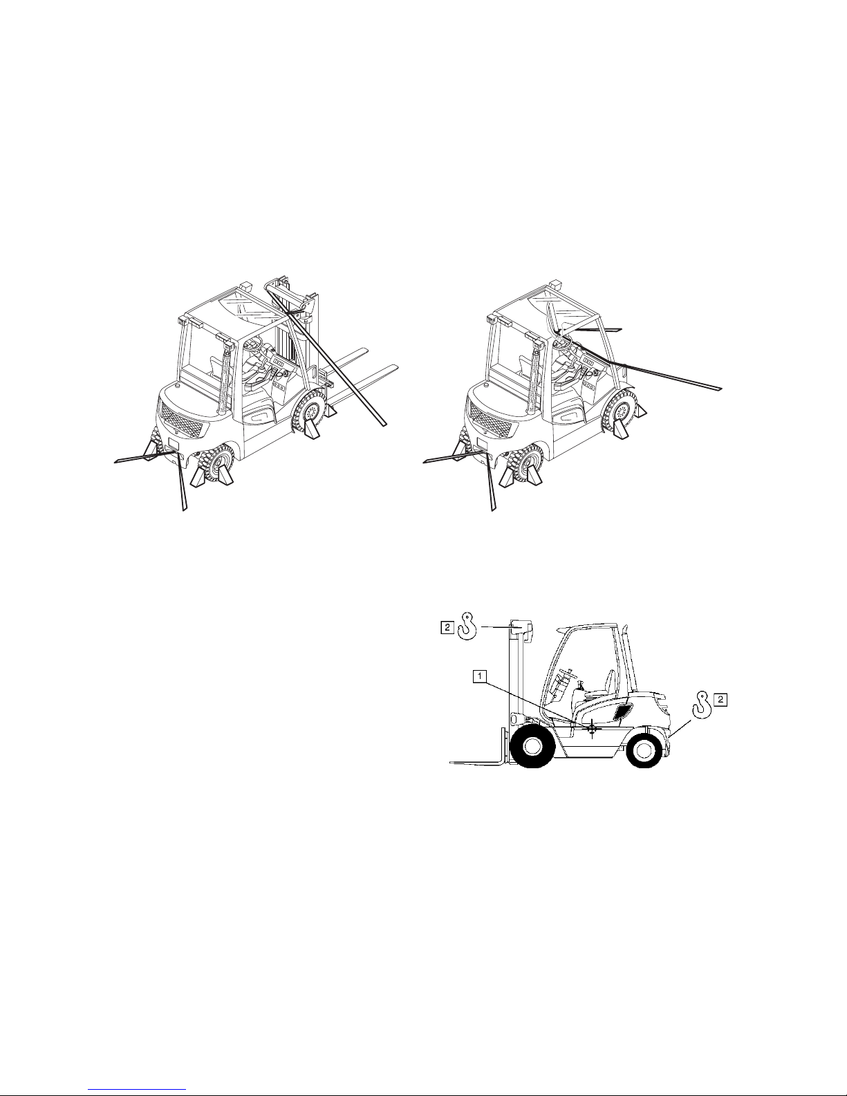
3 Securing the truck during transport
F
The truck must be securely fastened when being transported on a lorry or a trailer.
The lorry / trailer must have fastening rings and a wooden floor.
M
Loading must be carried out by specially trained staff in accordance with
recommendations contained in Guidelines VDI 2700 and VDI 2703. In each case
correct measurements must be made and appropriate safety measures adopted.
– To secure the truck with the mast assembled, use the eyes on the upper cross
member of the mast and the trailer pins.
– If the truck is to be transported without a mast, it must be tied down at the front of
the chassis.
The attached picture shows the
approximate centre of gravity location.
Page 26

C 3
04.08.GB
4 Using the truck for the first time
F
Commissioning and driver instruction must be performed by trained personnel. If
several trucks have been delivered, make sure that always the serial numbers of the
load handlers, masts and basic trucks match each other.
To prepare the truck after delivery or after transport, proceed as follows:
– Make sure the truck’s equipment is complete and in a satisfactory condition.
– Check the engine oil level.
– Hydrostatic drive axle oil level
– Check hydraulic oil level.
– Check battery terminals and acid level.
Start up the truck as indicated.
5 Operating the truck without its own drive system
The brake system is designed so that the multi-plate brakes are automatically
activated when the truck comes to rest. It must therefore be released for towing as
described below.
F
Support the mast and carriage on blocks before working underneath the forklift truck.
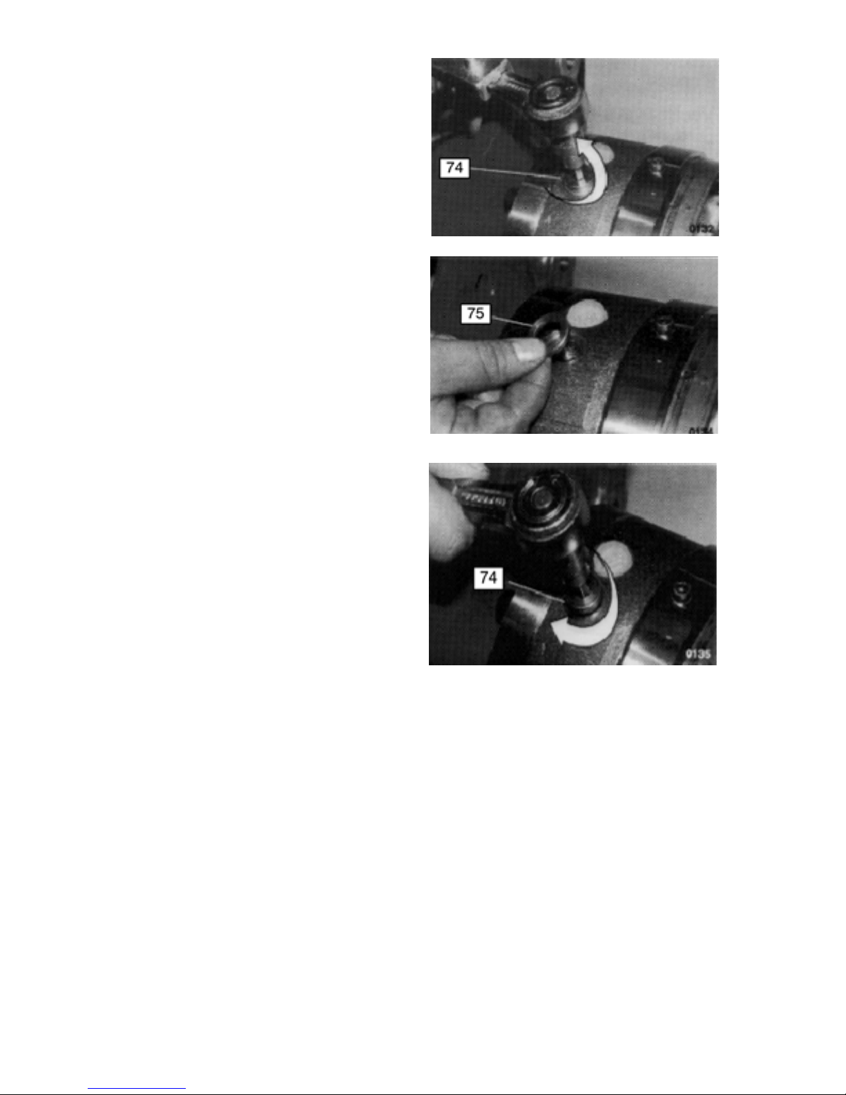
Releasing the mechanical brake
Should you need to tow the truck,
observe the following procedure:
Components
73 Ball
74 Plug
75 Washer
76 O ring
– Plug (74) position
Page 27
04.08.GB
C 4
– Remove the four plugs (74) from the
hydrostatic drive axle.
M
Leave the drive axle housing balls in
place.
– Pull out the washers (75) and
O rings (76).
– Refit the plugs (74) in pairs while
applying a torque of 30 Nm.
– Tow the truck slowly. You may
notice some resistance on the first
quarter turn of the wheels. This
depends on the period of time the
truck has not been in operation.
M
Towing a truck with a decommissioned engine will cause the hydrostatic drive axle to
overheat. To avoid this, the truck must only be towed a short distance at a maximum
speed of 4 km/h.
– After towing the truck it is essential to refit the washers and O rings. Failure to
comply with this instruction will prevent the emergency or parking brakes from
working.
– Remove the plugs (74) and washers (75) and attach new O rings (76). Torque the
plugs to 60 ± 6 Nm.
Page 28
C 5
04.08.GB
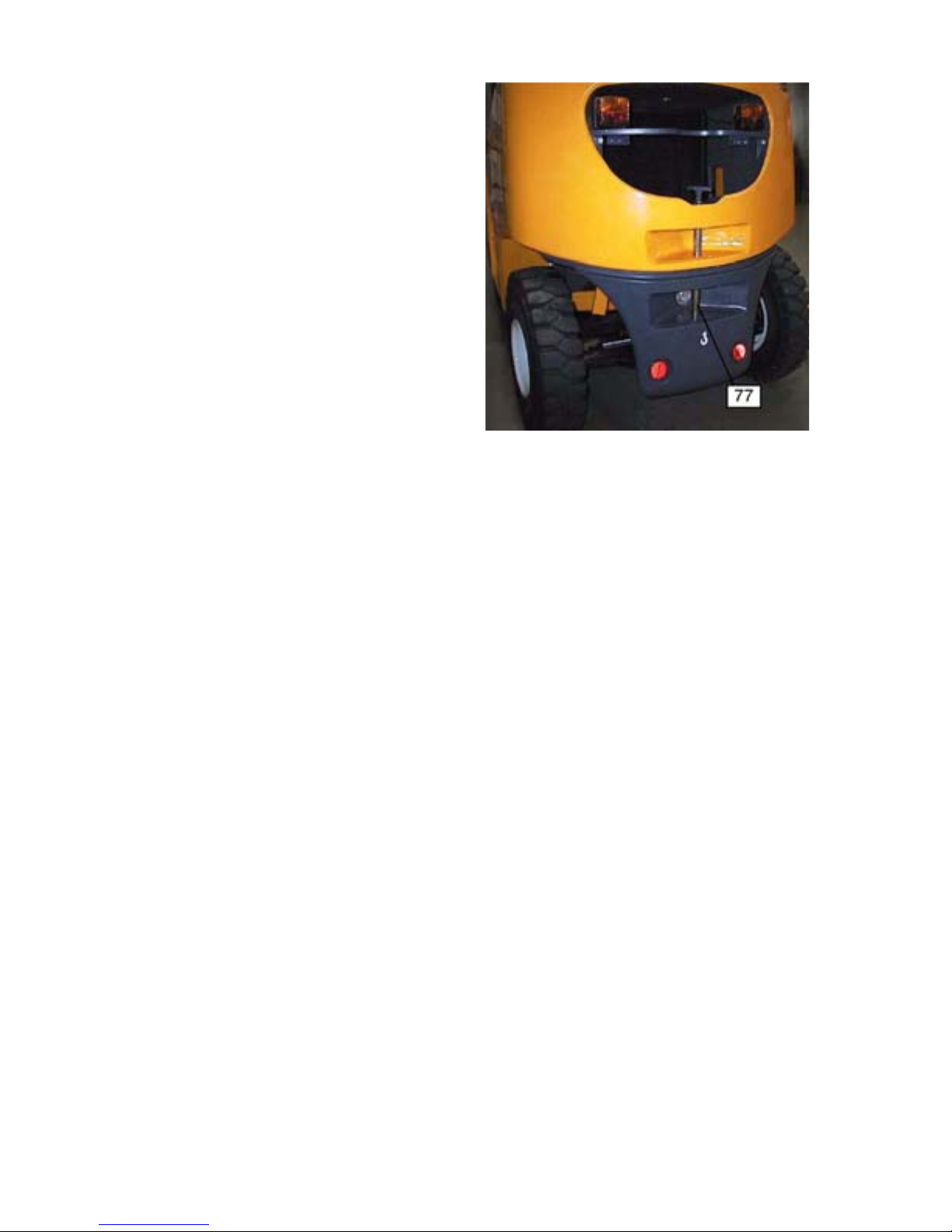
Hitch point
A rigid tow bar must be used to move
a forklift truck.
The tow point of the truck is
indicated (77).
Using the hitch point
– Push the tow pin (78) down and turn
it 90 degrees.
– Pull the tow pin up and insert the tow
eye or tiller of the trailer vehicle into
the opening (79).
– Insert the tow pin, push it down, turn
it 90 degrees and engage it.
F
One person must be seated in the towed truck to steer it. Tow the truck at walking
pace.
Z
As the steering auxiliary unit is not operational, extra effort is required to steer the
truck.
Page 29

04.08.GB
C 6
Page 30

D 1
04.08.GB
D Fuelling the Truck
1 Safety regulations for handling diesel fuel and LPG
Before filling up or replacing the LPG bottle, first park the truck securely (see Chapter E).
Fire protection: When handling fuels and LPG, smoking, naked flames and other
ignition sources are strictly prohibited in the immediate vicinity. Labels indicating the
hazard zone must be positioned where they are clearly visible. It is prohibited to store
flammable materials in this area. Fire equipment in full working order must be
provided within easy reach of the filling area.
F
Use only a carbon dioxide dry fire extinguisher or a carbon dioxide gas extinguisher
to fight LPG fires.
Storage and transport: The diesel and LPG storage and transport devices must
comply with statutory requirements. If there is no filling point available, the fuel must
be stored and transported in clean, approved containers. The contents must be
clearly indicated on the container. Unsealed LPG bottles must be brought
immediately into the open air, stored in well ventilated areas and the supplier must be
notified. Spilled diesel must be set using a suitable agent and disposed of in
accordance with environmental regulations.
Personnel for filling fuel and replacing LPG bottles: Personnel handling LPG
must be have sufficient knowledge of the nature of liquid gases to ensure safe
operation.
Filling up the LPG tank: LPG tanks remain connected to the truck and are filled up
at LPG stations. Always follow the instructions of the tank system and LPG container
manufacturer as well as statutory and local regulations when filling up.
Hose / pipe safety valve
M
Attention: A hose / pipe safety valve must be present when using fluid gas, to prevent
the gas from escaping suddenly if a line fails.
– Use only gas bottles with a hose / pipe safety valve.
– The bottle connection to the truck must have a hose / pipe safety valve (available
from the factory).
The owner must comply with all legal requirements, technical standards and health
and safety regulations applicable to liquid gas.
F
Liquid gas produces frost damage when it comes into contact with bare skin.
Page 31

04.08.GB
D 2
2 Filling with diesel
F
The truck must only be filled at locations
specifically designed for this purpose.
– Park the truck securely before filling
up (see Chapter E).
– Open the cap (1).
– Fill up with clean diesel.
Z
Do not overfill the tank.
Level:
DFG 316s/320s: 42 l
M
Only use DIN 590 diesel with a cetane
rating above 50.
The fuel indicator (2) shows the fuel
level. When the indicator points to the
red area the tank must be filled up.
M
Never allow the fuel tank to run dry. Air
in the fuel system will result in
malfunctions.
– Tighten the cap back on after filling
with fuel.
Page 32

D 3
04.08.GB
3 Replace the LPG bottle
F
The LPG bottle must only be replaced at designated areas by trained and authorised
personnel.
– Park the truck securely before
filling up (see Chapter E).
– Close the shut-off valve (3)
securely.
– Start the engine and allow the
LPG system to run empty in
neutral.
– Unscrew the union nut (4) with
an appropriate key while holding
against the handle (6).
– Remove the hose (5) and
immediately screw the valve cap
onto the empty LPG bottle.
– Slacken the sealing straps (8)
and remove the cover (7).
– Carefully remove the LPG bottle
from the bracket and place it
down securely.
F
Use only 18 kg (29l) LPG
replacement bottles.
– Insert the new LPG bottle in the
bracket and turn it so that the
neck of the shut off valve is
facing down.
– Secure the LPG bottle with the
sealing straps.
– Refit the hose in accordance with
regulations.
– Carefully open the shut off valve
and check the connection is
sealed using a foam-based
agent.
Page 33

04.08.GB
D 4
o Reusable LPG bottles with central filling device
F
Refillable liquid gas bottles contain a
dispensing valve (10), a filling stop valve
(11), a relief valve (12) and a level
display (13). To fill the tank close the
dispensing valve, unscrew the cover of
the filling stop valve and insert the
nozzle of the LPG pump into the filling
port. The filling stop valve automatically
stops the gas from being filled when the
bottle reaches the maximum level. At
filling, screw the lid back on.Observe
any guidelines or regulations on filling
LPG bottles that are attached to the LPG
pump.
Z
Safety notices:
– The tank and the fittings must be checked regularly for physical damage, corrosion
and other damage in accordance with the regulations of the country of use.
– Tank repairs must only be carried out by trained personnel.
o Lift trucks with two LPG bottles
F
A twin LPG bottle container may only be used if the truck is equipped with an
operational reverse camera system and outer mirrors on both sides.
A supply valve is also attached to the unit in addition to the shutoff valves on both gas
bottles. This valve can be used to select from which of the two bottles the gas is to be
taken. The two bottles cannot be used together.
M
Close both shutoff valves on the gas bottles to interrupt the supply of gas.
1110
13
12
Page 34

E 1
04.08.GB
E Operation
1 Safety Regulations for the Operation of Forklift Trucks
Driver authorisation: The forklift truck may only be used by suitably trained
personnel, who have demonstrated to the proprietor or his representative that they
can drive and handle loads and have been authorised to operate the truck by the
proprietor or his representative.
Driver’s rights, obligations and responsibilities: The driver must be: informed of
his rights and duties; trained in the operation of the forklift truck; and familiar with the
contents of these operating instructions. The driver shall be afforded all due rights.
Safety shows must be worn for pedestrian operated trucks.
Unauthorised use of truck: The driver is responsible for the truck during the time it
is in use. He shall prevent unauthorised persons from driving or operating the truck.
Do not carry passengers or lift other people.
Damage and Faults: The supervisor must be immediately informed of any damage
or faults to the forklift truck or attachment. Trucks which are unsafe for operation (e.g.
wheel or brake problems) must not be used until they have been rectified.
Repairs: The driver must not carry out any repairs or alterations to the industrial truck
without the necessary training and authorisation to do so. The driver must never
disable or adjust safety mechanisms or switches.
Hazardous area: A hazardous area is defined as the area in which a person is at risk
due to truck movement, lifting operations, the load handler (e.g. forks or attachments)
or the load itself. This also includes areas which can be reached by falling loads or
lowering operating equipment.
F
Unauthorised persons must be kept away from the hazardous area. Where there is
danger to personnel, warning shall be sounded in good time. If unauthorised
personnel are still within the hazardous area the truck shall be brought to a halt
immediately.
Safety devices and warning signs: Safety devices, warning signs and warning
instructions shall be strictly observed.
M
Trucks with reduced headroom are equipped with a warning sign within the driver's
line of sight. The max. recommended body size indicated on this sign must be
observed.
Page 35

04.08.GB
E 2
Page 36

E 3
04.08.GB
2 Controls and Displays
Item Control /
display item
Function
1 Parking brake
indicator
t When lit, indicates that the parking
brake is applied.
2 Fuel display (DFG) t Indicates how much fuel is left in the
tank.
3 Coolant temperature
indicator
t Indicates the coolant temperature.
4 Neutral position t When lit, indicates that the travel
direction switch is in neutral.
5 o Not used.
6 Hydrostatic drive
indicator
o When lit, indicates that the hydrostatic
drive is faulty.
Slow flashing indicates a minor error
in the hydrostatic drive, such as
accelerator potentiometer, mast lever
or engine actuator.
Rapid flashing indicates a more
serious error in the hydrostatic drive
(truck automatically brakes), such as
the pump potentiometer, brake pedal,
error in 5 volt circuit.
A permanently lit indicator during
travel indicates an error in the engine
speed sensor.
7Light o Indicates that the headlights are on.
8 Engine oil pressure
indicator
t When lit, indicates insufficient engine
lubricant oil pressure.
9 Not used o
10 Not used o
Page 37

04.08.GB
E 4
Page 38

E 5
04.08.GB
Item Control /
display item
Function
11 t Not used.
12 Seat belt indicator o When lit indicates that the seat belt
has not been properly attached.
13 Indicator control light o Shows the indicator status (right/left).
14 Fuel supply
indicator (DFG)
t When lit, indicates the fuel supply is
too low.
15 Time / service hours
display
t Indicates the time or number of
service hours operated.
16 Preheat control light
(DFG)
t Indicates the cold start mechanism is
operating.
17 Charge current
indicator
t When lit, indicates that the battery is
not charged.
18 Steering wheel t Steers truck in desired direction.
19 Set heating/air
connection
o
20 Steering column
adjusting lever
t Adjusts the steering column tilt.
Page 39

04.08.GB
E 6
Page 40

E 7
04.08.GB
Item Control /
display item
Function
21 Heating
o Controls the heating (page E13)
22 Accelerator pedal t Controls the engine speed and / travel and
lift speeds.
23 Raise/lower
control lever
t Raises and lowers the fork carriage. To
raise the fork carriage: pull the lever back.
To lower the fork carriage: push the lever
forward.
24 Mast tilt control
lever
t Tilts the mast forward and back.
To tilt the mast forward: push the lever
forward. To tilt the mast back: pull the lever
back.
25 Switch o Lamps, demister etc.
26 Ignition / starter
switch
t Switches power supply on and off.
Starts and stops the engine. Removing the
ignition key prevents the truck from being
switched on by unauthorised personnel.
27 Main switch /
isolator
(emergency
disconnect)
t Interrupts the main circuit, all electrical
functions are deactivated.
The engine switches off.
The truck brakes suddenly.
This switch should only be used to stop in
an emergency.
In normal circumstances the stopping
instructions listed on page E 25 should be
observed.
28 Warning switch
t Activates a warning sound.
29 Travel direction
lever
t Selects the travel direction.
30 Slow travel /
brake pedal
t 1st zone: controls slow travel.
2nd zone: applies service brake.
31 Parking brake
switch
t Applies / releases parking brake.
To engage, turn switch to position 1. To
release, turn switch to position 0.
32 5 level selector t Each level increases or reduces the
acceleration and brake speeds.
Page 41

04.08.GB
E 8
3 Operating the lift and tilt mechanisms (o)
Symbol Purpose Symbol Purpose
1. Tilt mast forward. 5. Tilt mast back.
2. Raise forks and tilt mast
forward.
6. Lower forks and tilt mast back.
3. Raise forks. 7. Lower forks.
4. Raise forks and tilt mast
back.
8. Lower forks and tilt mast forward.
Main control mechanism
Main control lever
Additional control levers
Page 42

E 9
04.08.GB
4 Twin Pedal Operation (o)
Introduction
This option enables the driver to control the travel direction with two pedals. The
system offers precise speed and direction control through two user-friendly pedals.
Right foot: forward. Left foot: backward.
Twin pedal
Direction / Accelerator Pedals
Pressing the direction pedal increases the engine speed and travel speed. When you
release your foot from the pedal, the truck slows down. Suddenly removing your foot
from the pedal causes the truck to slow down in a controlled manner and then stop.
Brake / slow travel pedal
When the brake / slow travel pedal is used in conjunction with a direction or
accelerator pedal, the speed and direction of the truck are controlled with precision.
Reverse /
accelerator pedal
Brake /
slow travel pedal
Forward /
accelerator pedal
Page 43

04.08.GB
E 10
t Gear shift lever
Z
When the gear shift lever is in the
middle position, the gear is in
neutral.
– To select forward gear, push the
lever forward.
– To select reverse gear, push the
lever back.
Z
The engine will not start when the
gear shift lever is in the forward or
reverse position.
Page 44

E 11
04.08.GB
o Gear selector mounted o the steering column
If your truck is equipped with a
steering column lever, it replaces
the standard gear selector.
Z
When the steering column lever is in
the middle position, the gear is in
neutral.
– To select forward gear, push the
lever forward.
– To select reverse gear, push the
lever back.
Z
The engine cannot start when the
lever is in the forward or reverse
position.
t 5 stage switch for travel mode
The Total Control System (TCS)
can control 36 performance
parameters. This provides a wide
range of setting options. To simplify
the complexity of this, five preprogrammed combinations can be
selected by the switch. The software
parameters have been designed to
correspond to five typical truck
applications. By simply shifting over
the 5 stage switch the truck’s
characteristics can be set to suit the
application at hand.
5 stage
switch
Parking brake
switch
Page 45

04.08.GB
E 12
M
Stop the truck and apply the parking brake. Select the required travel mode.
Z
The travel mode can only be altered when the truck is idle.
F
The truck can only be operated when the travel mode has been set correctly.
Z
The travel characteristics of trucks not fitted with a 5 stage switch are factory-set.
Loading / depositing: maximum performance and
productivity for intensive loading/unloading
operations over short distances and at low heights.
Outdoor operation: fast outdoor duty cycles over
short to medium distances, with medium heights.
Fast-reacting auxiliary hydraulics.
Mixed application: good all-round performance for
mixed operations.
Indoor operation: reduced engine speed. Basic
travel characteristics, high lift speeds. For controlled
working in tight areas.
Safety: reduced performance and exhaust levels
and low fuel consumption. For working with fragile
loads, in pedestrian zones, at night or noise-sensitive
areas.
Page 46

E 13
04.08.GB
o Heating controller
– Turn the thermostat control button (41)
anti-clockwise to reduce the driver's
cab temperature.
– Turn the fan control button (42)
clockwise to control the air flow. To
switch it off, turn the fan control button
to the O position.
– Push the air flow controller (43) as far
down as possible to direct the air flow
to the cabin floor. Push the air flow
controller (43) as far up as possible to
switch off the air flow to the cabin floor.
The air flow to the windscreen is
controlled independently of this lever.
Page 47

04.08.GB
E 14
Horn
– Press the button (25) to sound the
horn.
5 Tests and tasks to be performed before starting the truck
Truck
M
Visually inspect the whole of the truck (especially the wheels and the lifting device)
for obvious signs of damage.
– Test the seat belt (see page E21).
– Make sure the load chains are evenly tensioned.
Checking the engine oil - TFG
– Open the engine bonnet
(see page E 43).
– Remove the oil dipstick (44 / 46
or 48).
– Wipe the dipstick with a lint-free cloth
and put in back fully into its port.
– Remove the dipstick again and
check whether the oil level is
between the MIN and MAX
markings.
– If the oil level is below the centre
point, remove the fuel cap (43) and
add the correct grade of oil to the
engine until the oil level has reached
the MAX mark on the dipstick.
Page 48

E 15
04.08.GB
Checking the engine oil - DFG
– Remove the dipstick (50).
– Wipe the dipstick with a lint-free cloth
and put in back fully into its port.
– Remove the dipstick again and check
whether the oil level is between the
MIN and MAX markings.
– If the oil level is below the centre point,
remove the fuel cap (49) and add the
correct grade of oil to the engine until
the oil level has reached the MAX mark
on the dipstick.
Page 49

04.08.GB
E 16
Checking the hydraulic oil level
If the oil is cold
– Fully extend and retract the mast a
single time.
– Stop the engine.
– Remove the dipstick (53) and wipe it
with a clean cloth. Check the hydraulic
oil level. It should lie between the MIN
and MAX markings on the dipstick. If
necessary, top up to the MIN marking
on the dipstick.
If the oil is hot
– Fully extend and retract the mast a
single time.
– Stop the engine.
– Remove the dipstick (53) and wipe it
with a clean cloth. Check the hydraulic
oil level. It should lie just above the
MAX marking on the dipstick. If
necessary, top up to just above the
MAX marking on the dipstick.
Z
If the engine goes out or does not run
smoothly when the mast is extended,
lower the mast fully.
Page 50

E 17
04.08.GB
Checking the coolant level
– Cheeck the coolant level on the
reservoir (56).
The coolant level should be between
the “MIN” and “MAX” markings.
M
If the coolant is below the MIN
marking, this indicates possible
leakage in the radiator system. In this
case the truck should only be used
once the cause has been removed.
F
If the engine is hot, the radiator
system is pressurised. Slowly open
the reservoir lid until the pressure
has dropped.
When adding the coolant include a
premixed solution of water and antifreeze in the same concentration
levels as for a car.
Bleeding the coolant system
It should be possible to empty the system by opening the drain taps in the radiator
and on the side of the cylinder block. When bleeding the coolant system remove the
reservoir lid. Prevent the truck against authorised use.
Checking the fuel supply - (DFG)
– Set the ignition / starter key (26) to the
“I” position.
– Check the fuel supply on the fuel
gauge (2).
– If necessary, add diesel (see
Chapter D, Section 2).
Page 51

04.08.GB
E 18
Checking the windscreen fluid level
– Make sure there is sufficient
windscreen fluid in the container (1).
Top up if required.
– In winter, use windscreen fluid with
anti-freeze.
Wheels and Tyres
– Check wheels and tyres for wear (see
Chapter F). Measure the tyre pressure
(pneumatic tyres only) (see tyre
pressure table in Chapter B).
1
Page 52

E 19
04.08.GB
6 Starting up the truck
F
Before the truck can be commissioned, operated or a load unit lifted, the driver must
ensure that there is nobody within the hazardous area.
o Trucks with reduced headroom X
M
Failure to observe the recommended
body size can cause stress and
endanger the driver and may lead to
lasting ill health due to an unhealthy
posture and excessive strain on the
driver.
The owner must ensure that truck
operators do not exceed the max. body
size indicated.
In addition the owner must check that
the driver’s used can sit in an upright
position without having to strain.
Page 53

04.08.GB
E 20
6.1 Adjusting the driver’s seat
Z
To achieve optimum seat cushioning, the driver’s seat must be adapted to the driver’s
weight.
Adjusting the seat to the driver's weight:
– Sit on the driver’s seat. When the correct weight adjustment has been made, the
arrow of the driver weight display (59) will be above the calibration line. If the arrow
is facing too far to the left or right, the seat must be adjusted to the driver's weight.
– To do this, move the weight adjustment lever (1) approx. 90° forward.
– To set the seat to a lesser weight, push the weight adjustment lever (1) down.
– To set the seat to a greater weight, push the weight adjustment lever (1) up.
– After adjusting, return the lever to its original position.
To adjust the backrest:
– Sit on the driver’s seat.
– Lift up the backrest adjuster (2) and adjust the backrest tilt.
– Release the backrest tilt adjuster (2) to lock the backrest in position.
To adjust the seat position:
– Pull up the longitudinal adjuster (3) and push the driver’s seat forwards or
backwards to the desired position.
– Engage the longitudinal adjuster (3) in position again.
F
The longitudinal adjuster must be securely located in the desired position. The
driver’s seat setting must not be changed during travel.
59
1
2
3
Page 54

E 21
04.08.GB
6.2 Adjusting the steering column
– Release the steering column adjusting
lever (20) in the direction of the arrow
towards the driver’s seat (L).
– Tilt the steering column (62) forward or
backward as required.
– Push the steering column adjusting
lever in the direction of the arrow (F).
6.3 Seat belt
F
Put on the seat belt each time before starting the industrial truck.
The belt protects against serious injury.
Protect the belt from contamination (e.g. cover it when the truck is idle) and clean it
regularly. Frozen belt locks or pulleys must be thawed out and dried to prevent them
from freezing up again.
Z
The dry temperature of the warm air should not exceed +60 °C.
F
Do not alter the belt setting.
This will increase the risk of malfunctioning.
– Always replace the seat belt after an accident.
– Only original spare parts must be used for retrofits or repairs.
F
Damaged or non-operational belts must only be replaced by contractual dealers or
branches.
– Withdraw the belt completely and check the belt is frayed.
– Check the belt lock and that the belt enters the take up roller mechanism.
Check the cover for damage
Testing the automatic blocking system:
– Park the truck horizontally.
– Jerk the belt outwards.
M
The automatic system should lock the belt in the retractor.
– Open the engine bonnet by approx. 30°.
M
The automatic system should lock the belt in the retractor.
Starting the industrial truck on steep slopes
The automatic blocking system locks the belt in the retractor when the truck is
positioned on a steep slope. This prevents the belt from being pulled out of the
retractor.
Z
Carefully drive the truck off the slope and then put on the belt.
Page 55

04.08.GB
E 22
7 Starting the truck
Before starting the truck.
F
Before starting the truck, inspect the overhead guard for cracks and repair or replace
if damaged.
If the engine has not been run for several weeks or if the oil filter has been changed,
start the engine (see section 4.1 or 4.2) and leave it to run in idle for a few minutes
before starting.
Starting the engine
F
The truck should only be operated from the driver’s seat.
– Set the key switch to the I position.
– Set the travel direction lever to neutral “N”.
Z
The engine can only be started if the travel direction lever is in neutral and the parking
brake switch in the I position.
Key operated ignition
Key settings
Position Function
O=O° Disconnects all main circuits, the
key can be removed.
I=30° All consumers off
II=60° All consumers on
pre-heat Pre-heat
III=90° Start
Page 56

E 23
04.08.GB
7.1 Starting procedure for the TFG
F
Note the safety regulations for handling
liquid gas (see Chapter D, section 1).
– Slowly open the shutoff valve (63) on
the LPG bottle.
– Put the key in the ignition / starter
switch (26).
– Set the ignition / starter key to the “II”
position.
– Press the warning switch (28) and test
the horn.
The charging current (17), engine oil
pressure (8), neutral setting (4) and
parking brake (1) indicators light up.
– Gently apply the accelerator pedal
(22).
– Now move the ignition / starter key to
the “III” position.
M
Only apply the starter for a maximum of
15 seconds without interruption. Before
starting again, wait 30-60 seconds and
reset the ignition / starter switch to 0.
– Release the key as soon as the engine
starts. It automatically reverts to the
“II“ position.
F
When working with LPG trucks always
observe the following safety regulations.
If the truck does not start:
– Close the gas bottle shutoff valve.
– Turn off the ignition / starter O.
– Call for a trained, authorised customer
service engineer.
M
All indicators lights except for neutral
setting (4) and parking brake (1) should
go out as soon as the engine starts. If
not, stop the engine immediately and
rectify the fault.
Page 57

04.08.GB
E 24
7.2 Starting procedure for the DFG
– Put the key in the ignition / starter
switch (26).
– Set the ignition / starter key to the “II”
position.
– Press the warning switch (28) and test
the horn.
– After setting the ignition / starter (26) to
the II position, the charge current (17),
engine oil pressure (8), neutral setting
(4) and parking brake (1) indicators
will light up.
– Keep turning the key slowly until the
pre-heat indicator (16) goes on.
Z
On the DFG 316s/320s models if the bulb
does not go out, turn the ignition key to the
“III” position after approx. 4 seconds.
M
Only apply the starter for a maximum of
15 seconds without interruption. Before
starting again, wait 30-60 seconds and
reset the ignition / starter switch to 0.
– Release the key as soon as the engine
starts. It automatically reverts to the
II position.
M
All indicators lights except for neutral
setting (4) and parking brake (1) should
go out as soon as the engine starts. If
not, stop the engine immediately and
rectify the fault.
Page 58

E 25
04.08.GB
F
Once the engine has started, Carry out a
test run and perform the following
checks:
– Test the parking brake (31) and
service brake (30).
– Test the engine speed with the
accelerator pedal (22) over a range of
speeds while checking the freedom of
movement of the pedal.
– Test the operation of the raise/lower
(23), tilt (24) and if applicable the
attachment hydraulic control
functions.
– Turn the steering wheel (18) as far as
it will go in both directions and test the
steering.
M
Do not run up the engine in idle The
engine soon reaches operating
temperature at a moderate charge
and when the speed alternates.
Only fully charge the engine when
the engine coolant temperature
display (3) shows operating
temperature (indicator horizontal).
The truck is ready for operation
once all the functional controls have
been satisfactorily performed and
operating temperature is reached.
24
23
3
Page 59

04.08.GB
E 26
7.3 Operating Error Displays
When the following indicators are lit:
– Engine oil pressure (8),
– Charge current (17),
– Coolant temperature (3),
– Hydrostatic drive (6),
the engine must be stopped
immediately.
M
The engine should only be started
again once the fault has been
removed.
Z
For troubleshooting procedures, see
section 6.
When the truck is operating check
the fuel display (3) (DFG).
7.4 Switching off the engine
M
Do not switch off the engine from full
charge. Instead, let it run for a short
while to allow the temperature to
compensate.
– Stop the truck.
– Set the travel direction switch (29)
to neutral.
– Apply the parking brake lever (31).
– Set the ignition / starter switch
(26) to “0”.
M
Additional requirements for the
TFG:
Close the shutoff valve (63) on the
LPG bottle.
If the ignition key is set to “0” while
the engine is running, the engine will
continue to run for a short while. This
ensures that the remaining gas in
the lines between the engine and the
automatic shutoff valve of the gas
system is used up.
Page 60

E 27
04.08.GB
8 Industrial Truck Operation
8.1 Safety regulations for truck operation
Travel routes and work areas: Only use lanes and routes specifically designated for
truck traffic. Unauthorised third parties must remain clear of the work area. Loads
must only be stored in places specially designated for this purpose.
Driving conduct: The driver must adapt the travel speed to local conditions. The
truck must be driven at slow speed when negotiating bends or narrow passageways,
when passing through swing doors and at blind spots. The driver must always
observe an adequate braking distance between the forklift truck and the vehicle in
front and must be in control of the truck at all times. Abrupt stopping (except in
emergencies), rapid U turns and overtaking at dangerous or blind spots are not
permitted. Do not lean out or reach beyond the working and operating area.
Travel visibility: The driver must look in the direction of travel and must always have
a clear view of the route ahead. When carrying loads which affect visibility, these must
be stored at the rear of the truck. If this is not possible, a second person must walk in
front of the truck as a lookout.
Negotiating slopes and inclines: Slopes or inclines may only be negotiated if they
are designated traffic routes, are clean and have a non-slip surface and providing
they can be safely negotiated in accordance with the technical specifications of the
truck. The truck must always be driven with the load unit facing uphill. The industrial
truck must not be turned, operated at an angle or parked on inclines or slopes.
Inclines must only be negotiated at slow speed, with the driver ready to brake at any
moment.
Negotiating lifts and docks: Lifts and docks must only be used if they have sufficient
capacity, are suitable for driving on and authorised for truck traffic by the owner. The
driver must satisfy himself of the above before entering these areas. The truck must
enter lifts with the load in front and must take up a position which does not allow it to
come into contact with the walls of the lift shaft. People travelling in the lift with the
forklift truck must only enter the lift after the truck has come to a halt and must exit the
lift before the truck.
Nature of loads to be carried: The operator must make sure that the load is in a
satisfactory condition. Loads must always be positioned safely and carefully. Use
suitable precautions, e.g. a load guard, to prevent parts of the load from tipping or
falling down.
Page 61

04.08.GB
E 28
Towing trailers
(see page E46)
F
Exhaust emissions: The truck must only be operated in well ventilated areas. If the
truck is operated in enclosed areas, this can lead to a build-up of harmful exhaust
emissions, resulting in dizziness, tiredness and even death.
M
The user must comply with legal requirements, technical standards and health and
safety regulations when operating an IC engine powered lift truck in closed rooms.
Page 62

E 29
04.08.GB
9 Travel
F
Adapt the travel speed to the conditions
of the travel lane, the work area and the
load
– Set the travel direction switch (29) to
neutral.
– Raise the fork carriage approx. 200
mm so that the forks are clear of the
ground.
– Tilt the mast fully backward:
– Release the parking brake.
Forward travel
– Set the travel direction switch (29)
forward.
M
In normal operation do not set the
isolator (27) from max. speed to “OFF”.
The truck brakes automatically. (full
braking).
– Slowly apply the accelerator pedal
(22) until you reach the required travel
speed.
Changing direction
– Set the travel direction switch (29) via
neutral to the required direction.
– Slowly apply the accelerator pedal
(22) until you reach the required travel
speed.
Page 63

04.08.GB
E 30
Reversing
F
Make sure you have sufficient space to reverse into.
– Move the travel direction switch (29) backwards.
Accelerating
– Slowly apply the accelerator pedal (22) until the truck starts to move.
– Continue to depress the accelerator. The engine and travel speeds will increase.
Braking
F
The brake pattern depends largely on
the ground conditions. The driver must
take this into consideration when
handling the truck. Brake carefully to
prevent the load from slipping.
Braking
– Take your foot off the accelerator pedal (22). The truck brakes slowly.
– Depress the brake pedal (30) fully to increase the brake force.
Page 64

E 31
04.08.GB
9.1 Steering
F
Very little steering force is required for
the hydrostatic steering, therefore turn
the steering wheel (26) with caution.
9.2 Brakes
Service brake
The parking brake acts on the multi-plate
brakes via a hydraulic pressure system.
This system is fail-safe as the parking
brakes automatically apply in the event
of pressure loss.
– Take your foot off the accelerator
pedal (22).
The truck will brake hydrostatically
depending on the travel program that is
active.
Additional braking can be achieved by
pressing the brake / slow travel pedal (30).
The parking brake is applied during the
last movement of the brake / slow travel
pedal.
Parking brake
The parking brake switch secures the
automatic multi-plate brake in the brake
position.
To apply the parking brake set the switch
(31) to the I position.
To release the parking brake set the
switch (31) to the O position.
Page 65

04.08.GB
E 32
Z
Before leaving the truck apply the parking brake switch and switch off the engine.
An audible warning will sound if the parking brake is not applied.
F
The parking brake will keep the truck with the maximum permissible load, on a clean
concrete surface, at a 15% incline.
Page 66

E 33
04.08.GB
10 Mast and Attachment Operation
F
The control levers must only be operated from the driver’s seat.
The lift mechanism is operated by the control levers on the right-hand side of the
driver's seat.
Lifting/lowering the fork carriage
F
Never reach through the mast!
– Pull the control lever (23) back to raise
the fork carriage.
– Push the control lever (23) forward to
lower the fork carriage.
Tilting the mast forward / backward
F
When tilting the mast back, do not
position any part of your body between
the mast and the front wall.
– Pull the control lever (24) back to tilt
the mast back.
– Push the control lever (24) forward to
tilt the mast forward.
Operating attachments
Attachments are operated via the control
levers (25.26) to the right of control lever
(24) (mast tilt).
F
Note the manufacturer’s operating
instructions and the capacity of the
attachment.
Auxiliary hydraulics ZH1
The auxiliary hydraulics ZH 1 (control lever 25) can be used to control hydraulic
attachments (e.g. sideshift). They are applied by pressing the lever forward or pulling
it back.
1
Page 67

04.08.GB
E 34
Auxiliary hydraulics ZH2 +ZH3
The auxiliary hydraulics ZH2 (e.g. for
fork positioners) are controlled in the
same way as for ZH1 by applying the
control lever (26). You can toggle from
ZH2 to ZH3 with the switch (1).
o Intergrated sideshift ISS
The fork carriage can be moved sideways using the ISS.
– Sideshift left: Push the control lever (25) forward.
– Sideshift right: Pull the control lever (25) back.
F
Note the reduced capacity for sideshift (Chapter B, page 14)
o Integrated fork positioner
The integrated fork positioner allows the distance between the forks to be changed.
– Push the lever (26) to increase the fork spread
– Pull the lever (26) to reduced the fork spread
To synchronise the alignment of the forks, open them as far as the stop and then
close them again.
Other attachments
Z
Always follow the manufacturer’s operating instructions when using other
attachments.
Z
Mark the control levers with symbols to indicate their function.
M
The attachments must have a e mark. The reduced residual capacity must be
re-calculated and indicated on a separate capacity plate.
1
Page 68

E 35
04.08.GB
10.1 Controlling the speed of the lifting device
Moving the control levers (23-26) and
changing the engine speed governs the
operating speed of the hydraulic
cylinders.
When the control levers are released
(23-26) they automatically revert to
neutral and the lifting device remains in
the position it has reached.
M
Always apply the control lever
sensitively, never with a sudden jerk.
Release the control lever as soon as you
reach the stop.
– Set the travel direction switch (23) to
neutral
– Keep moving the control lever back to
increase the speed of the lifting
device.
Z
On the hydrostatic drive the engine
speed automatically increases as the
control lever is moved. (greater angle =
higher speed)
Z
The engine speed does not affect the
lowering speed of the fork carriage.
F
Do not lift other people with the lifting
device.
Page 69

04.08.GB
E 36
10.2 Lifting, transporting and depositing
load units
F
The control levers must only be operated
from the driver’s seat.
M
Before lifting a load the driver must make
sure that it has been correctly palletised
and does not exceed the truck’s
capacity.
Note the capacity chart.
Adjusting the forks
F
Adjust the forks in such a way that both
are equidistant from the outer edge of
the fork carriage and the load centre of
gravity lies between the forks.
– Raise the locking lever (65).
– Push the forks (66) into the correct
position on the fork carriage (67).
– Turn the locking lever down and move
the forks until the locking pin engages
in a slot.
Lifting loads
– Carefully approach the load to be
lifted.
– Set the travel direction switch (29) to
neutral.
– Raise the forks to the correct height for
the load.
– Set the travel direction lever to forward
travel.
Page 70

E 37
04.08.GB
– Carefully enter the load until ideally it
touches the fork shank.
F
At least two thirds of the length of the
load fork must extend into the load.
– Set the travel direction lever (29) to
neutral.
– Raise the fork carriage until the load
rests freely on the forks.
– Set the travel direction lever to
reverse.
F
Make sure you have enough space to
reverse into.
– Reverse carefully and slowly until the
load is outside the storage area.
Page 71

04.08.GB
E 38
F
Do not stand underneath a raised load.
– Tilt the mast back fully.
– Lower the load as far as is absolutely
necessary for transport (ground
clearance approx. 150…200mm).
F
The higher the load is transported, the
less secure the truck will be.
Page 72

E 39
04.08.GB
11 Transporting loads
F
If the load is stacked so high that it
affects forward visibility, then reverse.
– Gently accelerate with the accelerator
pedal (22) and slowly brake with the
slow travel / brake pedal (30), while
being ready to brake at all times.
– Adapt your travel speed to the
conditions of the route and the load
you are transporting.
– Watch out for other traffic at crossings
and passageways.
– Always travel with a lookout at
blindspots.
F
On slopes and inclines always carry the
load facing uphill, never approach at an
angle or turn.
Page 73

04.08.GB
E 40
Depositing a load
– Drive carefully up to the rack.
– Set the travel direction switch (29) to
neutral.
– Raise the forks to the correct height for
the rack space.
– Set the mast vertical.
– Set the travel direction lever to forward
travel.
– Carefully enter the load into the rack
space.
– Slowly lower the load until the forks
are clear.
M
Avoid placing the load down suddenly to
avoid damaging the load and the load aid.
Handling individually suspended loads
Travel at max. crawl speed when transporting suspended loads. For operations
involving suspended loads, the safety of the truck must be individually assessed by a
specialist.” The capacity is reduced by at least 1/3.
F
THE RATED CAPACITY OF THE TRUCK AND THE ATTACHMENT MUST NOT BE
EXCEEDED.
Page 74

E 41
04.08.GB
12 Hazardous situations
F
If the truck is about to tip over, never
undo the restraint belt and try to jump
out.
This will only increase the risk of injury.
Correct procedure:
– Lean your upper body over the
steering wheel.
– Grip the steering wheel with both
hands and brace feet.
– Lean your body against the opposite
direction of fall
Page 75

04.08.GB
E 42
12.1 Parking the truck safely
F
When you leave the truck it must be
securely parked even if you only intend
to leave it for a short time.
M
Never park and abandon a truck with a
raised load.
– Drive the truck onto a level surface.
F
LPG powered trucks must not be
operated on ground floors with a
basement.
Liquid gas is colourless, heavier than
air and does not easily dissipate. It
tends to sink to the lowest possible
level and can collect in pits, drains,
basements and other recesses.
This means that LPG gas can gather in
areas far away from the truck and
constitutes a hazard for people who
are unaware of the potential risks from
explosions and frostbite.
– Fully lower the load fork and tilt the mast forward.
– Set the travel direction switch (29) to neutral.
– Set the parking brake switch (31) to the I position.
Page 76

E 43
04.08.GB
13 Engine bonnet and service covers
Engine bonnet
Z
Before opening the engine
compartment push the steering
column as far forward as it will go and
push the seat fully back along its guide
rails.
– To open the engine compartment fit a
suitable instrument (e.g. screwdriver
(68)) through the access hole and
push it onto the locking device of the
engine bonnet (69).
– Lift up the engine bonnet fully. A gas
pressure damper keeps the engine
bonnet in the raised position.
M
If a forklift truck is equipped with a
steel cabin, both cabin doors must be
opened before raising the motor panel.
M
Make sure the engine bonnet has
engaged correctly before operating
the truck again.
To aid visibility the truck is shown
without a protective plate.
Page 77

04.08.GB
E 44
13.1 Service covers
When the engine bonnet has been
opened the service covers (70) can be
removed as follows:
To remove:
– Tilt the top of the cover plate away
from the truck and lift off the service
cover.
To assemble:
– Insert the bottom bracket of the
cover plate in the receptacles
provided.
– Push the top of the service cover
towards the truck until it engages.
o Steel cabin
If a truck is fitted with a steel cabin,
both doors can be closed.
– To unlock the cabin door turn the
key anti-clockwise.
– To lock the cabin door turn the key
clockwise.
– To open the cabin door, unlock the
door and remove the handle (71).
Page 78

E 45
04.08.GB
13.2 Towing the truck
– See chapter C, item 5
13.3 Towing trailers
The truck can occasionally be used to tow a light trailer on a dry, level and well
maintained surface.
Z
The max. tow load is the capacity indicated on the capacity data plate (see decals
diagram in chapter B).
The tow load consists of the weight of the trailer and the stated capacity.
If a load is transported on the forks, the tow load must be reduced by the same
amount.
F
Important notes for safe towing
• A truck must not be continually operated with trailers.
• No supporting loads are permitted.
• The maximum speed is 5 km/h.
• Towing must only be performed on level, secure travel routes.
• Follow the instructions of the coupling manufacturer if using special trailer
couplings.
• The owner must test trailer operation with the permissible tow load by means of a
trial run under the applicable operating conditions on site.
Page 79

04.08.GB
E 46
14 Troubleshooting
This chapter allows the user to identify and rectify basic faults or the effects of
incorrect operation. When locating a fault, proceed in the order shown in the table.
Z
If the fault cannot be rectified after carrying out the remedial procedure, notify the
manufacturer’s service department, as any further troubleshooting can only be
performed by specially trained and qualified service personnel.
Fault Possible Cause Action
Starter does
not turn
yTravel direction lever not in
neutral
yBattery charge too low
yBattery terminal cable loose or
terminals oxidized.
yStarter cable loose or broken
yStarter solenoid jammed
ySet the travel direction lever to neutral.
yCheck battery charge, charge battery if
necessary
yClean and grease terminals, tighten battery
terminal cable
yCheck starter cable, tighten or replace as
required
yCheck if the magnetic switch audibly engages
Engine does
not start
yAir filter contaminated
Additional for LPG
yLPG bottle shutoff valve closed
yLPG bottle empty
yIgnition distributor cap damp
ySpark plugs damp, oily or loose
ySpark plugs faulty
Additional for diesel
yFuel tank empty, injection
system has suctioned in air
yWater in fuel system
yClean / replace air filter
yShutoff valve open
yReplace LPG bottle
yDry ignition distributor cap, if necessary apply
contact spray
yDry, clean and tighten spark plugs
yReplace spark plugs
yFill up with diesel and bleed the injection system
yDrain the fuel system, fill up the truck, bleed the
fuel system
Engine does
not start
(continued)
yFuel filter blocked
yParaffin separation from the
diesel (flakes forming)
yCheck fuel flow, replace fuel filter if necessary
yPark the truck in a warm room and wait until the
separation has returned to its original state.
Replace the fuel filter if necessary. Add winter
diesel fuel
Page 80

E 47
04.08.GB
Fault Possible Cause Action
Engine oil
indicator lit
during
operation
yEngine oil level too low yCheck engine oil level, top up if necessary
Engine
temperature
display in red
zone
yEngine oil level too low
yRadiator contaminated
yCoolant level too low
yFan V belt slipping
yCheck engine oil level, top up if necessary
yClean radiator
yCheck engine radiator system for leaks, add
coolant if necessary
yCheck V belt tension, tighten or replace as
required
Transmission
oil indicator lit
during
operation
yTransmission oil level too low
yRadiator contaminated
yCheck transmission oil level, top up if necessary
yClean radiator
Engine
running but
truck does not
travel
ySet the travel direction lever to
neutral.
yParking brake applied
ySet travel direction lever to required direction
yRelease parking brake
Truck does not
reach max.
speed
yTransmission oil level too low yCheck transmission oil level, top up if necessary
Lift speed too
low
yHydraulic reservoir oil level too
low
yHydraulic reservoir discharge
system contaminated or
blocked
yCheck hydraulic oil, if necessary top up
yClean / replace hydraulic reservoir discharge
system
Load cannot
be raised to
max. height.
yHydraulic reservoir oil level too
low
yCheck hydraulic oil, if necessary top up
Steering is
sluggish
ySteering axle tyre air pressure
too low
yCheck tyre air pressure, increase to correct
pressure if necessary
Excessive
steering play
yAir in steering system yCheck hydraulic oil level and top up if necessary,
then turn the steering wheel several times from
one end to the other.
Page 81

04.08.GB
E 48
Page 82

F 1
07.08.GB
F Truck Maintenance
1 Operational Safety and Environmental Protection
The servicing and inspection duties contained in this chapter must be performed in
accordance with the intervals indicated in the maintenance checklists.
F
Any modification to the forklift truck assemblies, in particular the safety mechanisms,
is prohibited. Do not alter the truck operating speeds under any circumstances.
M
Only original spare parts have been certified by our quality assurance department. To
ensure safe and reliable operation of the truck, use only the manufacturer's spare
parts. Used parts, oils and fuels must be disposed of in accordance with the relevant
environmental protection regulations. For oil changes, contact the manufacturer’s
specialist department.
At the end of testing, cleaning and service operations carry out the procedures listed
under section 14 “Initial tests and tests after major repairs or modifications”.
2 Maintenance Safety Regulations
Maintenance personnel: The fork lift truck must only be serviced and maintained by
trained personnel of the manufacturer. The manufacturer’s service department has
field technicians specially trained for these tasks. We therefore recommend a maintenance contract with the manufacturer’s local service centre.
Lifting and jacking up: When an industrial truck is to be lifted, the lifting gear must
only be secured to the points specially provided for this purpose. When the truck is to
be jacked up, take appropriate measures to prevent the truck from slipping or tipping
over (e.g. wedges, wooden blocks). You may only work underneath a raised load
handler if it is supported by a sufficiently strong chain.
Z
For jack points see Chapter B.
Cleaning: Do not use flammable liquids to clean the industrial truck. Prior to cleaning,
all safety measures required to prevent sparking (e.g. through short circuits) must be
taken. For battery-operated trucks, the battery connector must be removed. Only
weak suction or compressed air and non-conductive antistatic brushes may be used
for cleaning electric or electronic assemblies.
M
If the truck is to be cleaned with a water jet or a high-pressure cleaner, all electrical
and electronic components must be carefully covered beforehand as moisture can
cause malfunctions. Do not clean with pressurised water.
F
Switch off the engine and remove the ignition key before opening any doors or bonnets or removing any panels. Always let the engine cool down before carrying out
maintenance and repair work.
Page 83

07.08.GB
F 2
Electrical System: Only suitably trained personnel may operate on the truck’s electrical system. Before commencing work on the electrical system, take all precautionary measures to avoid electric shocks.
Welding: Disconnect the battery (batteries) and generator before carrying out any
welding operations to avoid damaging electric or electronic components. The computer system on hydrostatic trucks must be unplugged. Welding operations on forklift
trucks must only be carried out by suitably qualified personnel.
Settings: When repairing or replacing hydraulic, electric or electronic components or
assemblies, always note the truck-specific settings.
Wheels/tyres: The quality of tyres affects the stability and performance of the truck.
Changes can only be made with the approval of the manufacturer. When replacing
wheels or tyres make sure that the forklift truck does not become uneven (i.e. when
replacing wheels always replace left and right together).
Lift chains: Lift chains wear rapidly if not lubricated. The intervals stated in the service checklist apply to normal duty use. More demanding conditions (dust, temperature) require more regular lubrication. The prescribed chain spray must be used in
accordance with the instructions. Applying grease externally will not provide sufficient
lubrication.
Hydraulic hoses: The hoses must be replaced every six years. When replacing
hydraulic components replace also the hoses in the hydraulic system.
Starter battery disposal: Batteries may only be disposed of in accordance with
national environmental protection regulations or disposal laws. Do not dispose of
used batteries with general waste. The manufacturer’s disposal instructions must be
followed. End users, both private and commercial, are legally obliged to return used
truck starter batteries to the battery manufacturer through the trade, i.e. wherever batteries are sold, or through authorized disposal agents. If in doubt, contact the Jungheinrich service department.
Page 84

F 3
07.08.GB
3 Servicing and Inspection
Thorough and expert servicing is one of the most important requirements for the safe
operation of the industrial truck. Failure to perform regular servicing can lead to truck
failure and poses a potential hazard to personnel and equipment.
M
The application conditions of an industrial truck have a considerable impact on the
wear of the service components.
We recommend that a Jungheinrich customer adviser carries out an application analysis on site to work out specific service intervals to prevent damage due to wear.
The service intervals stated are based on single shift operation under normal operating conditions. They must be reduced accordingly if the truck is to be used in conditions of extreme dust, temperature fluctuations or multiple shifts.
The following maintenance checklist states the tasks and intervals after which they
should be carried out. Maintenance intervals are defined as:
W = Every 50 service hours, at least weekly
A = Every 500 service hours
B = Every 1000 service hours, or at least annually.
C = Every 2000 service hours, or at least annually.
Z
W service intervals must be performed by the owner.
– During the run-in period – after approx. 100 service hours – the owner must check
the wheel nuts/bolts and re-tighten if necessary.
Page 85

07.08.GB
F 4
4 DFG/TFG maintenance checklist
Maintenance Intervals
Standard = z WA BC
Cold store = 7
Chassis/
Superstructure:
1.1 Check all load bearing components for damage
z
1.2 Check screw connection
z
1.3 Check overhead guard for damage and make sure it is secure
z
1.4 Check trailer hitch
z
Drive system: 2.1 IC engine – see separate checklist
2.2 Check transmission for noise and leakage
z
2.3 Check pedal mechanism, adjust and lubricate if necessary
z
2.4 Check transmission oil level
z
2.5 Change transmission oil
z
2.6 Clean transmission oil suction filter and discharge
z
2.7 Change transmission oil filter
z
2.8 Check drive axle for noise and leakage
z
2.9 Check drive axle oil level (hydrokinetic only)
z
2.10 Replace drive axle oil level (hydrokinetic only)
z
2.11 Check switching mechanism on switch lever for wear and
lubricate the contact surfaces (hydrokinetic only)
z
2.12 Lubricate drive axle / mast swivel axle (hydrokinetic only).
z
Brake
system:
3.1 Test operation and settings
z
3.2 Check brake lining wear (hydrokinetic only)
z
3.3 Check brake mechanism, adjust and lubricate if necessary
(hydrokinetic only)
z
3.4 Check brake lines, connections and brake fluid level (hydrokinetic only)
z
3.5 Change brake fluid (hydrokinetic only)
z
Wheels: 4.1 Check wheels for wear and damage
z
4.2 Check suspension and attachment
z
4.3 Check air pressure
z
Steering: 5.1 Check the steering play
z
5.2 Check the mechanical parts of the steering column; grease if
necessary
z
5.3 Check steering axle, axle knuckle, stops for wear and deformation
z
5.4 Test operation of hydraulic components and check for leaks
z
Mast: 6.1 Check mast attachment
z
6.2 Check and lubricate mast suspension
z
6.3 Check operation, wear and setting
z
6.4 Visually inspect rollers, slide pieces and stops
z
6.5 Check lift chains and guides for wear, adjust and lubricate.
z
6.6 Check lateral slack and ensure mast sections are parallel
z
6.7 Check forks and fork carriage for wear and damage
z
6.8 Check protective mechanisms for damage and make sure
they are secure
z
6.9 Check tilt cylinder suspension and attachment
z
6.10 Check mast tilt angle
z
Page 86

F 5
07.08.GB
Maintenance intervals
Standard = z WA BC
Cold store = 7
Hydraulic
System
7.1 Test operation z
7.2 Check connections and ports for leaks and damage z
7.3 Check hydraulic cylinder for leaks and damage and make
sure it is secure
z
7.4 Check oil level z
7.5 Replace hydraulic oil
7.6 Replace filter cartridge z
7.7 Clean hydraulic oil suction filter and discharge z
7.8 Test operation of pressure relief valves z
7.9 Test hose guide and check for damage z
Electrical
system
8.1 Test operation z
8.2 Make sure wire connections are secure and check for damage z
8.3 Test all warning devices and safety switches. z
8.4 Test operation of instruments and displays z
Battery: 9.1 Check acid density, acid level and battery voltage z
9.2 Check terminals are securely attached, and apply terminal
screw grease
z
9.3 Check battery cables for damage, replace if necessary. z
Attachment: 10.1 Test operation z
10.2 Check attachment on truck and load bearing components z
10.3 Check position of bearings, guides and stops for wear and
damage, grease these components.
z
Lubrication: 11.1 Lubricate truck in accordance with Lubrication Schedule. z
General
Measurements:
12.1 Test travel speed and braking distance z
12.2 Test lift and lowering speeds z
12.3 Test safety devices and cutouts z
Demonstration:
13.1 Test run with rated load z
13.2 After carrying out maintenance, present the truck to the supervisor.
z
Page 87

07.08.GB
F 6
5 DFG maintenance checklist
d) Replace coolant annually.
Maintenance intervals
Standard = z WA BC
Cold store = 7
Engine: 1.1 Check engine for noise and leaks z
1.2 Check injection pump flow start, adjust if necessary z
1.3 Check injection nozzle pressure, adjust if necessary z
1.4 Tighten cheese head screws z
1.5 Check valve play, adjust if necessary z
1.6 Check engine oil level, top up if necessary z
1.7 Replace the engine oil. z
1.8 Replace the engine oil filter z
1.9 Check V belt for tension and damage z
1.10 Check maximum speed (without load), adjust if necessary z
Coolant: 2.1 Check coolant level, top up if necessary z
2.2 Check anti-freeze content, top up if necessary z
Exhaust: 3.1 Check exhaust system for leaks and damage z
3.2 Check exhaust levels, adjust if necessary z
Air filter: 4.1 Clean air filter cartridge z
4.2 Replace air filter cartridge z
Hydraulic
system:
5.1 Check and lubricate the hydraulic pump drive z
Fuel system: 6.1 Replace the fuel filter z
6.2 Check fuel/water separator, and discharge if necessary z
6.3 Check fuel tank and lines for leaks and damage z
Page 88

F 7
07.08.GB
6 TFG maintenance checklist
d) Replace coolant annually.
Maintenance intervals
Standard = z WA BC
Cold store = 7
Engine: 1.1 Check engine for noise and leaks z
1.2 Check spark plugs, replace if necessary z
1.3 Check ignition time, adjust if necessary z
1.4 Check ignition distributor, adjust if necessary z
1.5 Check valve play, adjust if necessary z
1.6 Check engine oil level, top up if necessary z
1.7 Replace the engine oil z
1.8 Replace the engine oil filter z
1.9 Check V belt for tension and damage z
1.10 Check maximum speed (without load), adjust if necessary z
Coolant: 2.1 Check coolant level, top up if necessary z
2.2 Check anti-freeze content, top up if necessary z
Exhaust: 3.1 Check exhaust system for leaks and damage z
3.2 Check exhaust levels, adjust if necessary z
Air filter: 4.1 Clean air filter cartridge z
4.2 Replace air filter cartridge z
Hydraulic
system:
5.1 Check and lubricate the hydraulic pump drive z
LPG system: 6.1 Check LPG system for leaks and damage z
6.2 Have LPG filter replaced by specialist z
6.3 Have LPG system examined by specialist z
6.4 Have the exhaust pollutant levels checked by a specialist and
adjust to the lowest level achievable.
z
6.5 Check and service Impco units z
Page 89

07.08.GB
F 8
7 Coolant specification
The quality of the coolant has a considerable effect on the efficiency and useful life of
the cooling system. The following instructions are designed to provide the best servicing in terms of frost and corrosion protection.
– Always use clean, soft water.
– To avoid frost and corrosion damage use an ethylene-glycol based anti-freeze mix-
ture. Use a standard anti-freeze with a pH value of 7.0 – 8.5.
– Make sure the mixture ratio is correct when using an anti-freeze. The frost protec-
tion level must satisfy the above standard.
The manufacturer cannot be held liable for frost or corrosion damage caused by
incorrect procedures.
F
The anti-freeze contains ethylene-glycol and other poisonous substances.
Ingression into the human body can result if large quantities come into contact
with the skin for long or repeated periods.
When handling anti-freeze always observe the following safety measures:
– NEVER swallow anti-freeze. If anti-freeze is accidentally swallowed, seek IMMEDI-
ATE medical attention.
– Avoid prolonged skin contact with anti-freeze.
– Wipe off spray from the skin immediately.
– If anti-freeze is sprayed into the eyes, rinse them immediately.
– Clothing sprayed with anti-freeze must be removed and washed before being worn
again.
– Wear protective clothing if you are regularly handling anti-freeze (plastic or rubber
gloves, boots and non-permeable overalls or aprons).
F
Anti-corrosion solutions contain additives which are poisonous if swallowed
and which can be absorbed in poisonous quantities through persistent,
repeated contact with the skin. Observe the same safety precautions as for
anti-freeze.
U.S.A. ASTM D4985 or SAE J1941 Ethylene—glycol based engine coolant
Lowest temperature
required for protection
% volume of anti-freeze Volume ratio
of anti-freeze:
water
-37 °C 50 1:1
Page 90

F 9
07.08.GB
8 Consumables
Handling consumables: Consumables must always be handled correctly. Follow
the manufacturer’s instructions.
F
Improper handling is hazardous to health, life and the environment. Consumables
must only be stored in appropriate containers. They may be flammable and must
therefore not come into contact with hot components or naked flames.
Only use clean containers when filling up with consumables. Do not mix consumables
of different grades. The only exception to this is when mixing is expressly stipulated
in the Operating Instructions.
Spilled liquids must be removed immediately with suitable bonding agents and the
bonding agent / consumable mixture must be disposed of in accordance with regulations.
Z
The volumes indicated are approximate.
Z
Bio oils
Bio-degradeable hydraulic oils may only be used after consultation with the relevant
JH service department.
Grease guidelines
9 DFG fuel specifications
Use only DIN EN 590 diesel with a Cetane rating above 50.
Code Order no. Capacity Description Used for
A 52017728 55 l HVLP46 Hydraulic system
B 50055726 K-P-2K grease
C 29201280 Chain spray Chains
D 51094056
4.3 l TFG
8.2 l DFG
Titan Unic Plus SAE 10W-40 Engine oil
Code Saponification Dew point °CWorked penetra-
tion at 25 °C
NLG1 class Application
temperature °C
E Lithium 185 265-295 2 -35/+120
Page 91

07.08.GB
F 10
10 Lubrication chart
Key to lubrication chart 10.1 - DFG/TFG
Item Description Lub. type
1. Chain rollers B
2. Lift chains C
3. Mast channels B
4. Tilt cylinder bolts B
5. Hydrostatic drive axle. A
6. Hydropump A
7. Displacement pump A
8. Hydraulic oil and filter A
9. Hinges and locks B
10. Steering axle hub B
11. Steering knuckle pins B
12. Knuckle bolts B
13. Engine oil and filter D
14. Pedals B
15. Mast and fork carriage rollers B
Page 92

F 11
07.08.GB
10.1 Lubrication chart - DFG/TFG
Page 93

07.08.GB
F 12
11 Maintenance and repairs
11.1 Preparing the truck for maintenance and repairs
All necessary safety measures must be taken to avoid accidents when carrying out
maintenance and repairs. The following preparations must be made:
– Park the truck securely (see Chap-
ter E, Section 5.8).
– Pull the key out of the ignition/
starter switch (2) to prevent the
truck from being switched on acci-
dentally.
– Turn off the main switch/isolator (1).
– When work has to be performed
under the raised fork or under the
jacked up truck, suitable meas-
ures must be taken to prevent any
dropping, tilting or slipping of the
fork or truck.
F
Note the following when raising the
forklift truck:
M
Only use lifting gear with sufficient capacity (for transport weight see truck data plate).
– Park the truck securely (see Chapter E, Section 5.8).
– Attach crane slings to the mast at the appropriate points.
– Attach the crane slings to the counterweight of the trailer coupling.
M
The crane lifting gear couplings must be fitted in such a way that they do not touch
any attachments or the overhead guard during lifting.
11.2 Starting aid
M
Only use an ISO 6722 battery jump lead with fully insulated terminal pliers and a lead
diameter of at least 25 mm
2
.
Procedure:
– First connect the red lead to the positive terminal
– Connect the black lead to the feeder battery and the earth point on the engine block
– Start the engine with the ignition key
– When the engine has started first remove the negative lead-then remove the posi-
tive lead
Z
Note: If the starter motor does not switch on the engine after connecting the battery
terminals, check that the battery terminal clips are positioned correctly.
Page 94

F 13
07.08.GB
11.3 Servicing the engine - TFG 316s/320s
Replacing the engine oil and
engine oil filter
M
Only change the engine oil when the
engine is at operating temperature
and the truck is horizontal. Always
replace the engine oil and engine oil
filter together.
Draining the engine oil
– Unscrew the lid (3).
– Thoroughly clean the oil drain plug
(4) and around the drain hole.
– Unscrew the oil drain plug and
drain the oil into a suitable con-
tainer.
F
Risk of scalding through hot oil.
– Screw in the oil drain plug with a
new seal.
F
Dispose of used oil in accordance
with environmental regulations.
Replace the engine oil filter
– Undo the oil filter (5) with a filter
wrench and manually unscrew it.
F
Collect any emerging oil and dispose
of the oil and oil filter in accordance
with environmental regulations.
– Thoroughly clean the raised faces
of the oil filter flange.
Page 95

07.08.GB
F 14
– Apply a thin layer of fresh engine
oil to the seal of the new oil filter.
Hand-tighten the oil filter.
Adding engine oil
– Add fresh engine oil through the filler
port in accordance with the consum-
ables table (see Section 8).
Capacity: 4.3 l
– Check the engine oil level with the
dipstick (6) and adjust as neces-
sary (see Chapter E, Section 3).
– Screw the lid back on.
– Fully insert the dipstick again.
M
After changing the oil and the oil filter, note the engine oil pressure indicator (7) when running the engine
again and check the oil drain plug
and oil filter are sealed.
Page 96

F 15
07.08.GB
Replacing the spark plugs
– Remove spark plug connector (8).
– Thoroughly clean around the spark
plugs on the cylinder head.
– Unscrew the spark plugs.
– Check the electrode distance of
the new spark plugs with a feeler
gauge, and adjust as required.
Rated value: 0.8 mm
M
Only use original spark plugs.
– Manually screw in the spark plugs
and then torque them to 20 Nm.
Checking the V belt tension
– Insert the V belt between the fan V
belt pulley (9) and the generator V
belt pulley (10) using a force of 45 N.
It should be possible to insert the V
belt after approx. 11 mm.
Adjusting the V belt tension
– Undo the screws (11) and pull the
AC generator (12) until you reach
the prescribed V belt tension.
– Re-tighten the screws.
– Check the V belt tension again and
repeat the adjustment if neces-
sary.
Page 97

07.08.GB
F 16
11.4 Engine servicing - DFG 316s/320s
Replacing the engine oil and
engine oil filter
M
Only change the engine oil when the
engine is at operating temperature
and the truck is horizontal. Always
replace the engine oil and engine oil
filter together.
Draining the engine oil
– Unscrew the lid (13).
– Thoroughly clean the oil drain plug
(14) and around the drain hole.
– Unscrew the oil drain plug and
drain the oil into a suitable con-
tainer.
F
Risk of scalding from hot oil.
– Screw in the oil drain plug with a
new seal.
F
Dispose of used oil in accordance
with environmental regulations.
Replace the engine oil filter
– Undo the oil filter (15) with a filter
wrench and manually unscrew it.
F
Collect any emerging oil and dispose
of the oil and oil filter in accordance
with environmental regulations.
– Thoroughly clean the raised faces of the oil filter flange.
– Apply a thin layer of fresh engine oil to the seal of the new oil filter.
– Hand-tighten the oil filter.
Page 98

F 17
07.08.GB
Adding engine oil
– Add fresh engine oil through the
filler port (16) in accordance with
the consumables table (see Sec-
tion 8).
Capacity: 8.2 l
– Check the engine oil level with the
dipstick (6) and adjust as neces-
sary (see Chapter E, Section 3).
– Screw the lid back on.
– Fully insert the dipstick again.
M
After changing the oil and the oil filter, note the engine oil pressure indicator (18) when running the engine
again and check the oil drain plug
and oil filter are sealed.
Checking the V belt tension
– Insert the V belt between the fan V
belt pulley (19) and the generator
V belt pulley (20) using a force of
100 N.
It should be possible to insert the V
belt after approx. 5 mm.
Adjusting the V belt tension
– Undo the screws (21) and pull the
AC generator (22) until you reach
the prescribed V belt tension.
– Re-tighten the screws.
– Check the V belt tension again and
repeat the adjustment if neces-
sary.
Page 99

07.08.GB
F 18
Replacing the fuel filter
– Drain the fuel from the filter into a
suitable container.
– Undo the fuel filter (23) with a filter
wrench and manually unscrew it.
F
Dispose of the fuel filter and fuel in
accordance with environmental regulations.
– Screw the fuel filter with a new O
ring into the new fuel filter.
– Before assembling, apply a thin
layer of diesel to the O ring.
– Thoroughly clean the raised faces
of the filter flange.
– Apply a thin layer of diesel to the
seal of the new fuel filter.
– Manually screw in the fuel filter
until the seal contacts the filter
flange.
– Tighten the fuel filter another third
of a turn.
– Bleed the fuel system
Bleeding the fuel system
F
Collect any emerging fuel and dispose of it in accordance with environmental regulations.
– Open the discharge screw (24).
– Apply the manual pump lever on
the fuel pump (25) until fuel
escapes from the discharge screw
without bubbles.
– Tighten the discharge screw.
– Set the ignition / starter key to the I
position for approx. 10 seconds.
– Wait for 10 seconds.
– Repeat the process until the
engine starts up.
M
While running the engine check the
fuel filter, the discharge valve and the
union nuts of the injection nozzles for
leaks.
Z
If the engine does not start up or
stops after a short time, repeat the
bleeding procedure.
Page 100

F 19
07.08.GB
11.5 Checking the coolant concentration
F
Do not open the radiator lid when the engine is hot.
To prevent the build up of lime as well as front and corrosion damage, and to raise
the boiling point temperature, the cooling circuit must be filled each year with a mixture of water and anti-freeze with anti-corrosion additives.
– If there is insufficient anti-
freeze, drain the coolant and
add anti-freeze to the reservoir
(68) until you obtain the correct
proportion in the mixture.
M
Use anti-freeze in accordance
with the coolant specifications
(see section 7).
The water/anti-freeze mixture
proportion and the degree of frost
protection to be achieved can be taken from the anti-freeze specifications.
Cooling circuit capacity:
DFG 316s/320s: 9.0 l
TFG 316s/320s: 9.0 l
11.6 Filling the cooling circuit
F
Leave the engine to cool down in order to fill it with coolant. Slowly open the lid; dangerously hot coolant can escape if the coolant circuit is still pressurized. Do not add
too much coolant to the circuit. The lid contains a safety valve which opens to let hot
coolant dissipate if the fluid level is too high.
M
If coolant is added in the course of servicing, it must meet the specifications of the
original fluid (see Section 7). If you add coolant too quickly or if the truck is not horizontal, air will enter the cooling circuit. Running the engine with air in the coolant circuit will result in excessive operating temperatures and can damage the engine.
 Loading...