

Page 1

SLT 100
SLT 100
Operating instructions
50451882
SLT 100
G
10.04 -
11.15
Page 2

V1
11.15.GB
Foreword
The safe operation of the charger requires
the application of expertise contained in the
present ORIGINAL OPERATING
INSTRUCTIONS. The information is
presented in a precise and clear manner.
The chapters are arranged by letter.
Our equipment is subject to ongoing
development. We reserve the right to alter
the design, features and technical aspects
of the equipment. No guarantee of
particular features of the truck should
therefore be assumed from the present
operating instructions.
Safety instructions and important
explanations are indicated by the following
graphics:
F
Used before safety instructions which must
be observed to avoid danger to personnel.
M
Used before notices which must be
observed to avoid material damage.
Z
Used before notices and explanations.
t Used to indicate standard equipment.
o Used to indicate optional equipment.
Copyright
Copyright of these operating instructions
remains with JUNGHEINRICH AG.
Jungheinrich Aktiengesellschaft
Friedrich-Ebert-Damm 129
D-22047 Hamburg - Germany
Tel: +49 (0) 40/6948-0
www.jungheinrich.com
Page 3

I1
0709.GB
Table of contents
A Correct use and
application 1
B Description of battery
charger 2
1 Technical description 2
2 Charging electronics 4
3 Protection / Ambient conditions 4
4 Identification label, 4
C Transportation and
Commissioning 5
1 Transporting the charger 5
2 Charger Assembly 5
3 Starting up the charger 5
D Battery - Servicing,
recharging, replacement 6
1 Safety regulations governing
the handling of lead-acid
batteries 6
E Operation 7
1 Safety regulations relating to
the operation of battery chargers 7
2 Description of the operating
controls and indicating elements 8
3 Commissioning the battery
charger 9
3.1 Connecting the charger 9
3.2 Starting the charging operation 9
3.3 Battery charging sequence 9
3.4 Mains supply 9
3.5 Fault indication (safety cut-out) 9
3.6 Manual charging interruption 10
3.7 Boosting charge 10
3.8 Manual Compensation Charge 10
3.9 Automatic equilising charge
function 10
4 Charging state indicator 10
F Charger Maintenance 11
1 Operational safety and
environmental protection 11
2 Safety instructions to
be observed during servicing 11
3 Cleaning operations 11
4 Working on the SLT 100
charger 11
5 Fuses 11
5.1 Small battery charger 11
5.2 Large battery charger 12
G Internal electrolyte stirrer
(EUW) 13
1 Correct use and application 13
2 Charger Assembly 13
3 Electrolyte circulation (EUW) 13
4 Description of the device 13
5 Commissioning 15
5.1 Air volume flow presetting 15
6 Maintenance of the filter 15
7 Aid for malfunctions 16
7.1 Malfunction: Pump does not
react during charging. 16
7.2 Malfunction: Charging time is
not reduced 16
7.3 Malfunction: Loud pump noises 16
H “LIS” charge information
system (
o) 17
I Sample data plate 18
Page 4

I2
0709.GB
17
1115.GB
H “LIS” charge information system (o)
Chargers with the charge information
system (LIS) store the data from the last
200 charges.
The curves for the individual charges can
be viewed on a PC. The necessary
software is supplied on a CD with the
charge information system.
Z
For information on operating the charge
information system, software installation
instructions and PC connection to the
charger, see “Charge information system”
operating instructions.
Page 5

1
1115.GB
A Correct use and application
The SLT 100 battery charger is designed
for the fully automatic charging of lead
batteries and may only be operated for this
purpose. The charger operates in
accordance with the Wa characteristic
specified in DIN 41774. This characteristic
is optimized by current pulses at the end of
the charge. This current characteristic
curve, which slopes downwards as the
battery charge level rises, allows for optimal
charging. Safe functioning of the battery
charger is ensured by the reliable charging
electronics monitoring the battery charging
operation.
The technical data and specifications
regarding the connection requirements can
be found on the identification plate and in
the operating instructions. These
specifications must always be heeded.
Operation of the battery chargers is subject
to the provisions contained in the relevant
legislation and regulations, from industry
association guidelines (VDE), from the
EMC directive (2004/108/EC) and
directives issued by local authorities.
Excerpts of such provisions are given in
chapter E1.
The battery charger must only be used for
charging batteries which are of the type
stipulated by the manufacturer.
The battery charger must always be
operated with the housing closed. It is
forbidden to loosen and remove parts of the
housing or any type of suppressor
elements.
Do not place any objects on the charger or
climb onto it.
Additional components may only be
installed after a written approval by the
manufacturer has been obtained.
User obligations:
User within the meaning of these operating
instructions is any natural person or legal
person who either uses the battery charger
himself, or on whose behalf it is used.
In special cases (e.g. leasing or renting),
the user is deemed to be the person, who,
in accordance with existing contractual
agreements between the owner and the
user of the SLT 100 battery charger, is
charged with the observance of the
operating duties.
The user is responsible for choosing the
assembly location. He must check whether
the battery charger will affect any devices
that are sensitive to electromagnetic
interference.
The assembly location of the charger must
be chosen so that operation (high DC
currents generate magnetic interference
fields) does not affect the functioning of
sensitive electromagnetic devices and
magnetic data media, such as
pacemakers, monitors, disks, magnetic
tapes, magnetic cards, watches, see
“Charger Assembly” on page 5.
The user must ensure that the SLT 100
battery charger is used only within its
design limits and that all danger to life and
limb of the operator and third parties is
avoided.
Furthermore, applicable accident
prevention and other health and safety
regulations, along with the operating and
maintenance guidelines, must be observed
at all times.
M
The battery charger must only be operated
when stationary.
The user must also ensure that all persons
operating the battery chargers have read
and understood these operating
instructions.
Page 6
2
1115.GB
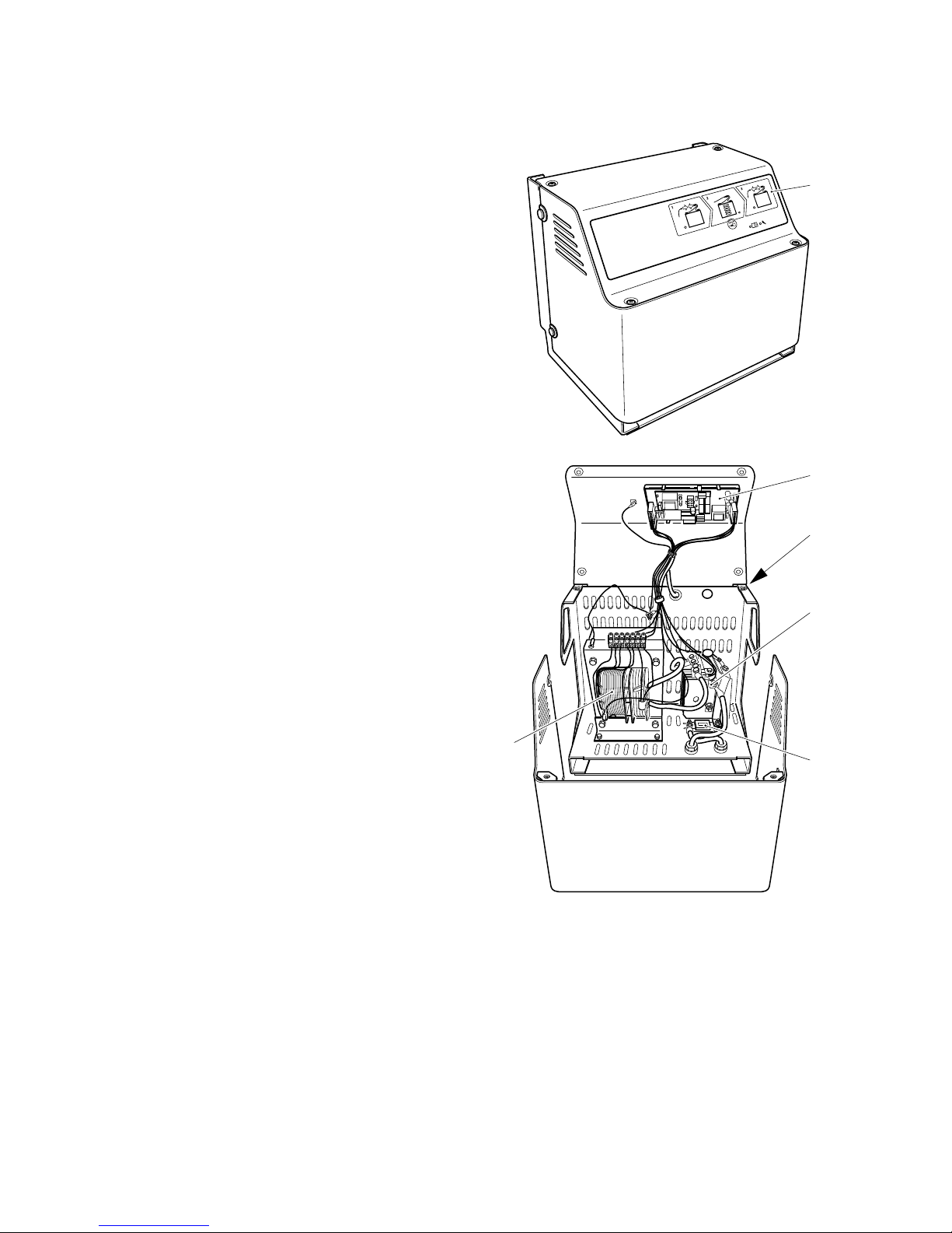
B Description of battery charger
1 Technical description
The SLT 100 battery charger is designed
for the fully automatic charging and
recharging of lead batteries and is
equipped with a special electronic charging
system (1, 2). The rated charging current
specified flows at a charging voltage of
2.0 volts per cell. The battery must be
assigned so that the initial charging current
is approx. 16 Amperes per 100 Ah of
battery capacity.
The difference lies in the initial charging
current – see data plate (3).
Initial charging voltage: 24, 48, 80 volt
depending on type
Initial charging current: 20 A-160 A,
depending on type
The battery charger is protected on the
secondary side by a fuse (5) acting as
a short circuit protection and by a sensor to
limit the transformer temperature.
To ensure the operational safety of the
system, only self-cooled stacked silicon
rectifier elements (4) are used.
Stray field transformers (6) are used to
comply with the specified charging
characteristic.
The stray field transformers are equipped
with additional primary tapping to
DIN 41 774, corresponding to +10 %,
+5 %, 0 % and -5 % to allow for mains
voltage deviations.
Z
Modifications should only be carried out by
the manufacturer’s service department.
2
3
1
4
5
6
SLT 100
SLT 100
15
1115.GB
5 Commissioning
Z
For transport and assembly see chapter C
on page 5.
For chargers with electrolyte circulation the
air volume flow must also be adapted to the
battery, see "Air volume flow presetting” on
page 15.
5.1 Air volume flow presetting
Switch (3) has the following factory settings
for all SLT 100 large battery chargers:
6 Maintenance of the filter
The blue suction filter (5) on the bottom of
the pump must be checked for soiling at
regular intervals.
In strongly dusty areas, it is to be replaced
every 3 months, otherwise at least every 6
months.
To replace the suction filter (5) tip the blue
insertion sleeve to the side and replace the
polishing cotton.
Figure: Large battery charger
Figure: Small battery charger
Voltage class
in V
Volume in l/min
24 4
48 8
80 12
Item Description
4 Cable to the charging switch
5 Filter
6 Air hose
4
5
6
6
54
Page 7

3
1115.GB
Charging electronics extra option
(Aquamatic)
Z
The Aquamatic serves to control an
external solenoid valve of an automatic
water refilling system.
When a cell voltage of 2.4 V/cell is reached,
a relay contact (normally open contact,
contact rating 5 A) is triggered by the
following pulse train:
- 6-7 pulses with a duration of 3 sec., then
maintained contact for 7 min.
The contact is potential-free, a 230 V power
connection of the battery charger is
available.
Electrolyte circulation:
Z
The charger has an option for controlling an
electrolyte circulation pump.
M
Observe the respective manufacturer’s
guidelines! It should only be connected by
the manufacturer’s service department.
The Aquamatic and electrolyte circuluation
systems are monitored. Any faults are
displayed on the front panel.
M
The connection of external additional
equipment may only be carried out by
skilled electricians.
Z
To attach additional external equipment,
contact the manufacturer’s service
department.
Charging curve / pulse charging:
-T1 = Battery gassing phase reached.
Start of the recharging phase
-T2 = Start of the pulse charging phase
(1-5 pulses depending on the main
charging time)
-T3 = End of battery charge.
Z
If the battery remains attached to the
charger at the end of the charging time
(T3), there will follow an 8 minute trickle
charge every 8 hours and after 24 hours a
one-off compensation charge lasting
2 hours.
Characteristic curve:
Wa Charging characteristic
Uz Cell voltage (V/cell)
ILCharging current
(in % of rated current)
IdN Rated battery current
The curve of the Wa characteristic is
determined by points 1), 2) and 3):
1) 100 % I
dN
at V = 2.0V/cell
2) 50 % I
dN
at V = 2,4V/cell
3) 25 % I
dN
at V = 2,65V/cell
Z
A controlled thorough acid mixing by means
of current pulses is carried out at the end of
the recharging phase.
T
U, I
T1
T2 T3
2,8V
2,6
2,4
2,2
2,0
1,8
2,65
0 25 50 75 100%
1)
2)
3)
IL / I
dN
U
Z
Page 8

4
1115.GB
2 Charging electronics
The SLT 100 charging electronics monitor
and control the charging operation.
Progress of the charging operation is
shown by the light-emitting diodes (7).
An electronic monitoring unit detects the
gassing time and determines the optimum
recharging time from the charged capacity
(Ah balancing).
Charging starts automatically with a time
delay (approx. 10 sec. to protect the plug
contacts) after the battery has been
connected to the charger.
The control key (12) can be used to cancel
operation at any time.
The standby (13), charging (7), charging
completed (9), and compensation
charge (8) conditions are indicated by the
LEDs (13,7,9,8).
An automatic safety cut-out is provided,
when the gassing voltage has not been
reached within an initial charging phase of
12 hours.
Z
The automatic safety cutout is displayed by
the yellow warning display LED (11)
(flashing code): 3x / interval / 3x.
If the transformer overheats, a warning
is indicated (11) (flashing code: 4x /
interval / 4x). As soon as the transformer
temperature is in the permissible range
again, charging will be continued and the
LED goes off.
Optimum battery charging requires
adaptation to the mains supply. The
charging electronics are zero-voltage proof,
i.e. no malfunctions are possible as a result
of mains failures, as all times are stored
and charging will recommence at the point
the failure had occurred.
3 Protection / Ambient conditions
Protection: IP 22
Ambient conditions:
The charger is self-cooled and is designed
for a max. ambient temperature of
40 °C and a max. relative humidity of 80 %.
Minimum ambient temperatures:
- for storage -20 °C
- for operation 0 °C
If the charger thaws due to sudden
temperature changes, leave the charger for
a least 3 hours before switching it on again.
M
The charger must only be stored in
enclosed areas. Operation of the battery
charger is only permitted in spaces
specially provided for this purpose.
4 Identification label,
e.g. E230 G24/50 SLT 100
(see “Sample Data Plate” on page 18)
Z
The identification label is located on the
rear wall of the unit.
13 12 11 10 9
87
D = 3-phase curr
E = Alternating curr
Mains voltage (V)
Charging rectifier
Initial charging voltage (V)
Initial charging current (A)
Battery load
E 230 G 24 / 50 B SLT 10
0
13
1115.GB
G Internal electrolyte stirrer (EUW)
1 Correct use and application
Z
See also Chapter A ,“Correct use and
application”.
The battery charging device with a built-in
pump and hose system is suitable only for
batteries with electrolyte stirring.
User obligations:
The user must make sure that only
batteries with electrolyte stirring or with a
hose system are permitted to be charged.
M
The pump must not be operated without
counterpressure.
2 Charger Assembly
F
The battery charger must not be operated
outdoors.
Choose the assembly location so that:
- There is sufficient ventilation.
- The flow of cooling air through the
charger is not restricted. It must not be
installed close to radiators or similar heat
sources.
- No flammable gases or dust mixtures
can penetrate inside the charger.
- The charger is placed only on a solid and
secure surface. The surface must not
consist of flammable material.
- The bottom of the charger is approx.
0.5 m above the battery to be charged.
F
It is forbidden to store food in the vicinity of
battery chargers.
Z
The VDE 0510 safety regulations must be
observed.
3 Electrolyte circulation (EUW)
During charging the electrolyte circulation
pump is switched on for approx. 2.5 min.
and off for approx. 7 min.
Charging is recognised by the charge
switch insofar as it:
- Detects the connected battery.
- Detects a charge current.
During the pulse charge phase there is no
electrolyte circulation. The pump is
switched off.
4 Description of the device
During the main charging phase, batteries
without electrolyte circulation generate acid
layers. The charging factor is set according
to the charging device.
Internal electrolyte circulation:
Internal electrolyte stirring is automatically
switched on at the beginning of the
charging procedure. Electrolyte stirring
mixes the acid before the gassing phase.
Z
In the main charging phase, the battery’s
energy consumption increases so that the
recharging phase can be shortened.
The internal charging electronics detect via
the sensor that the pump is switched on
and reduce the recharging time. This
shortens the total charging time at the same
battery charge level.
Page 9

5
1115.GB
C Transportation and Commissioning
1 Transporting the charger
F
Always wear solid leather safety boots and
gloves when transporting and assembling
the charger.
Before starting the charger make sure it is
complete and in satisfactory working order.
2 Charger Assembly
F
The battery charger must not be operated
outdoors.
M
Fire hazard Flammable materials must not
be located in the immediate vicinity of the
battery charger. This includes transport and
packaging material delivered with the unit.
- No flammable materials must be located
within 2.5 metres of the battery charger
Choose the assembly location so that:
- There is sufficient ventilation.
- The flow of cooling air through the
charger is not restricted. It must not be
installed close to radiators or similar heat
sources.
- No flammable gases or dust mixtures
can penetrate inside the charger.
- The charger is placed only on a solid and
secure surface. The surface must not
consist of flammable material.
F
It is forbidden to store food in the vicinity of
battery chargers.
Z
The VDE 0510 safety regulations must be
observed.
Operations to be carried out before
assembly or installation of the battery
charger
Procedure
- Remove packaging material (film or
cardboard).
- If the battery charger was delivered on a
transport pallet, lift the battery charger
from the transport pallet
Z
This does not apply to pallets on which the
battery charger is permanently mounted.
These pallets have a fireproof base.
- Packaging material is to be disposed of
correctly.
Z
In addition to the restrictions listed in the
operating instructions, national requirements must be observed when choosing
the place of installation.
3 Starting up the charger
Charging cable connection:
The SLT 100 charger is supplied with
a charging cable.
The charging cable connections with strain
relief can be accessed when the yellow
panel is opened.
M
Use only the charging cables provided by
the manufacturer.
Mains connection:
M
All operations involving the opening of the
charger must be performed solely by
trained and authorized electricians.
F
Remove the battery and mains plugs before
opening the charger.
The mains voltage must correspond with
the mains voltage indicated on the
identification label. The identification label
is located on the rear wall of the unit.
M
Fuse protection of the mains cable to the
battery charger is the responsibility of the
customer. The fuse must have a delayaction release characteristic. Where
automatic cut-outs are used, they must
have a D, S or K rating (for the rated current
consumption of the charger see data plate).
To ensure adequate selectivity, the backup
fuse should at least be 10 % above the
current consumption of the charger.
The charger must be protected against
excessive contact voltage in accordance
with the regulations of the local electricity
provider.
Page 10

6
1115.GB
D Battery - Servicing, recharging, replacement
1 Safety regulations governing the
handling of lead-acid batteries
Maintenance personnel:
Recharging, servicing and replacing of
batteries must only be performed by
qualified personnel. The instructions
contained in this operating manual, and the
instructions as prepared by the battery
supplier must be observed, when
performing the above operations.
F
Metal watch bracelets, bracelets and
necklaces must not be worn when handling
batteries!
Fire protection measures:
Smoking and open flames are not permitted
when handling batteries. There must be no
flammable substances within at least 2.5
metres and no equipment capable of
creating sparks (e.g. machine tools) within
at least a 1 metre radius of the truck when
it is parked for battery recharging. It is
forbidden to operate devices with a high
surface temperature (e.g. soldering irons,
heater blowers, etc.).
Place the charger only on a solid and
secure surface.
M
The surface must not consist of flammable
material.
F
Charging batteries leads to the generation
of explosive gases. Sufficient ventilation
must be provided during charging and at
least for one hour after charging has been
completed.
The room must be ventilated. Check the
ventilation system each time before you
charge. Fire fighting equipment must be
held ready.
M
Parts that can be sucked in due to the
suction of the ventilation fans must not be
stored in the vicinity of the battery charger.
Clogged ventilation slits cause overheating
and fire hazard.
F
Do not use water to cool overheated battery
chargers.
Battery servicing:
The battery cell screw caps must be kept
dry and clean. Terminals and cable shoes
must be clean, lightly greased with pole
grease and must be securely tightened.
F
Batteries contain dissolved acid, which is
toxic and caustic. For this reason protective
clothing and goggles must be worn
whenever work is undertaken on batteries.
Avoid physical contact with battery acid.
If clothing, skin or eyes accidentally come
into contact with battery acid, liberally rinse
the affected parts with clean water. If it has
come into contact with the skin or eyes,
seek medical attention. Spilled battery acid
should be neutralised immediately with
plenty of water.
11
1115.GB
F Charger Maintenance
1 Operational safety and environmental
protection
The SLT 100 charger is maintenance-free.
It does not need to be cleaned regularly.
F
Any modification to the SLT 100 charger, in
particular its safety mechanisms, is strictly
prohibited.
M
Only original spare parts have been passed
by our quality assurance service. In order to
ensure safe and reliable operation,
exclusively use spare parts supplied by the
manufacturer. Old parts, oils and fuels must
be disposed of in accordance with the
applicable environmental protection
regulations.
2 Safety instructions to be observed
during servicing
Maintenance personnel:
Maintenance and repair of SLT 100
chargers must only be carried out by
qualified personnel.
The manufacturer’s service department
has field technicians specially trained for
these tasks.
3 Cleaning operations
F
Disconnect the unit from the mains before
starting cleaning work.
Do not use flammable liquids to clean the
charger.
4 Working on the SLT 100 charger
F
Operations of any kind on the battery
chargers must only be performed by
qualified electricians. Prior to the
commencement of any work on a battery
charger, all required measures must be
taken to prevent electric shocks.
5 Fuses
Z
The fuses used depend on the model.
5.1 Small battery charger
- Primary:
F2 fuse (15)
- Secondary:
F1 fuse (16)
- electrolyte circulation pump/
Aquamatik (o):
F3 fuse (14)
M
Version and rated value of the fuses must
not be changed. Refer to label showing the
rated values.
15
F2
14
F3
16
F1
Page 11

7
1115.GB
E Operation
1 Safety regulations relating to the
operation of battery chargers
To ensure the safety of a battery charger,
the equipment (charger, cables, battery)
must be in good working order. Operation
must be in such a way that no danger is
posed to persons.
F
Check the insulation before using the
charging cables and connectors.
Faults and defects must be rectified
immediately by trained personnel
(see “Safety instructions to be observed
during servicing” on page 11).
The following items are taken from the legal
requirements and guidelines of German
and international associations and
organizations.
Ventilation:
Battery chargers must be set up so that
they are not exposed to charging gases and
electrolytic mist.
Chargers and batteries must therefore be
housed in separate locations wherever
possible. If this is not possible, adequate
natural and artificial ventilation must be
provided to ensure that the gas mixture
generated during charging will lose its
explosiveness.
Functional test:
When commissioning new charging
equipment, and thereafter at adequate
intervals, checks must be performed to
ensure correct operation of the battery
charger, and especially correct functioning
of automatic charging switches and
measurement instrument display.
At the start of charging, the amperage and
voltage must be checked in order to detect
any irregularities in the patterns of the
battery or charging equipment.
Mains supply:
If, in the event of mains voltage fluctuations
lasting over a long period of time, the output
voltage changes, the battery chargers must
be readjusted ensuring that the admissible
limits as indicated by the battery supplier
are observed (e.g. final charging current in
the case of lead batteries).
Z
Short-time mains voltage fluctuations may
be ignored.
Charger assignment:
The charging procedures, or charging
characteristics, as well as the charging
equipment must be adapted to the
operating conditions and technical data of
the batteries.
Battery charging:
The connector must only be disconnected
from the socket after the battery charger
has been switched off. The top of the
battery cells must be exposed during
recharging to ensure adequate ventilation.
Do not rest any metal objects on the
batteries.
Z
Note the battery manufacturer’s
regulations.
M
Do not exceed the temperature limits
stipulated by the battery supplier. This
applies also to any heating that may occur
as the battery is recharged.
Page 12

8
1115.GB
2 Description of the operating controls and indicating elements
1 3 5 6 7
42
Item Operating control /
indicating element
Function
1 “Standby” LED (green)
t
lights up when the battery charger is ready for operation
2 “Charging” LED
(yellow)
t
indicates the charging process
3 Control key
t
The control key has the following functions:
- Stop / Continue charging (break function)
- Manual equilising charge
- Charging state indicator
4 LED
”Compensation
charge”
t
indicates the equilising charge
5 LED
“Warning messages”
(yellow)
t
Indicates faults that affect charging, via a flashing code.
Flashing pulses:Meaning:
2 Incorrect battery voltage
3 Safety charge exceeded
(Main charging time or recharging time in case of
pulse charging)
4 Excess temperature
5 Mains failure (is only indicated when the charging
state indicator is queried)
6 Warning requested by the optional board.
The exact error is indicated on the optional board.
6 LED
“Service messages”
(red)
t
Indicates problems, via a flashing code, that can only be rectified by
repair work
Flashing pulses:Meaning:
2 Charging switch or current measurement defective
3 Voltage coding/setting incorrect
4 Service message requested by the options board.
The exact error is indicated on the optional board.
7 “Charging completed”
LED (green)
t
Charging complete, battery is fully charged.
t = Standard equipment o = Optional equipment
9
1115.GB
3 Commissioning the battery charger
3.1 Connecting the charger
M
When connecting the charger, make sure
the contact of the charging cable is secure.
A poor contact, for instance at the charging
connection, can result in constant charging
current fluctuations which will affect the
charging electronics and show an incorrect
charging current display.
3.2 Starting the charging operation
When the mains plug is connected, the
green “Standby” LED (1) lights up.
The battery charger automatically switches
on when the charger and the battery are
connected. The first yellow LED (2) on the
charge display lights up.
Z
Charging is delayed by approx. 5 to
7 seconds in order to prevent charging
connector sparking.
Charging will not start, as long as the
battery voltage is outside the expected
range.
3.3 Battery charging sequence
Charging is indicated by the ascending
yellow “Charge” LED's (2) on the charge
indicator.
When the battery is fully charged, the green
“Charging completed” LED (7) lights up.
The battery charger automatically stops
charging.
Trickle charging:
When the battery remains connected, every
8 hours, following the completion of the
charging operation, a trickle charge is
initiated lasting for 8 minutes. The yellow
LEDs (2) light up. The green LED (7) for
“Charging complete” goes off during the
trickle charge phase.
Z
The battery charger automatically
terminates charging when the charging
time has elapsed. This process is repeated
for as long as the battery is connected to
the charger.
3.4 Mains supply
Mains failure:
If the battery is connected, a mains failure
will stop the time basis of the charging
switch and store the position of the
charging program.
All LED displays go out. When the mains
supply is restored the LEDs display the
previous condition. The battery charge
continues. The stored charging indication,
however, will be lost, when a mains failure
occurs without a battery being connected.
Low voltage:
Dropping below the admissible charging
current, for instance as a result of low
mains voltage, requires longer charging
periods or can result in insufficient charging
(warning message).
3.5 Fault indication (safety cut-out)
Gassing voltage:
If the battery does not reach the gassing
voltage within 12 hours, the safety system
interrupts the charging operation.
The yellow warning LED (5) flashes (3x /
interval / 3x). Disconnect the battery from
the battery charger and check it.
Battery voltage:
In the event of battery overvoltage or
undervoltage, the charge switch will not
start up charging. The yellow warning
LED (5) flashes (2x / interval / 2x). Observe
a short pause, until the battery voltage is
within the expected range. Check the
voltage class of the battery, if necessary.
Transformer overheating:
A sensor interrupts charging in the event of
excessive transformer temperature.
The yellow warning LED (5) flashes (4x /
interval / 4x). When the transformer cools
down to the permissible temperature, the
error indication goes off and charging is
continued.
Charging switch error:
The red “Service message” LED (6)
flashes. Disconnect the battery from the
mains, then restart the charging operation.
Check the battery assignment and adjust if
necessary. Otherwise notify the
manufacturer’s authorised customer
service department and withdraw the
charger from use.
Z
The operating state “Charging
completed” (7) can only be cancelled, when
the battery connector is removed from the
charging socket. This will prevent
unintentional double chargings.
Page 13

9
1115.GB
3 Commissioning the battery charger
3.1 Connecting the charger
M
When connecting the charger, make sure
the contact of the charging cable is secure.
A poor contact, for instance at the charging
connection, can result in constant charging
current fluctuations which will affect the
charging electronics and show an incorrect
charging current display.
3.2 Starting the charging operation
When the mains plug is connected, the
green “Standby” LED (1) lights up.
The battery charger automatically switches
on when the charger and the battery are
connected. The first yellow LED (2) on the
charge display lights up.
Z
Charging is delayed by approx. 5 to
7 seconds in order to prevent charging
connector sparking.
Charging will not start, as long as the
battery voltage is outside the expected
range.
3.3 Battery charging sequence
Charging is indicated by the ascending
yellow “Charge” LED's (2) on the charge
indicator.
When the battery is fully charged, the green
“Charging completed” LED (7) lights up.
The battery charger automatically stops
charging.
Trickle charging:
When the battery remains connected, every
8 hours, following the completion of the
charging operation, a trickle charge is
initiated lasting for 8 minutes. The yellow
LEDs (2) light up. The green LED (7) for
“Charging complete” goes off during the
trickle charge phase.
Z
The battery charger automatically
terminates charging when the charging
time has elapsed. This process is repeated
for as long as the battery is connected to
the charger.
3.4 Mains supply
Mains failure:
If the battery is connected, a mains failure
will stop the time basis of the charging
switch and store the position of the
charging program.
All LED displays go out. When the mains
supply is restored the LEDs display the
previous condition. The battery charge
continues. The stored charging indication,
however, will be lost, when a mains failure
occurs without a battery being connected.
Low voltage:
Dropping below the admissible charging
current, for instance as a result of low
mains voltage, requires longer charging
periods or can result in insufficient charging
(warning message).
3.5 Fault indication (safety cut-out)
Gassing voltage:
If the battery does not reach the gassing
voltage within 12 hours, the safety system
interrupts the charging operation.
The yellow warning LED (5) flashes (3x /
interval / 3x). Disconnect the battery from
the battery charger and check it.
Battery voltage:
In the event of battery overvoltage or
undervoltage, the charge switch will not
start up charging. The yellow warning
LED (5) flashes (2x / interval / 2x). Observe
a short pause, until the battery voltage is
within the expected range. Check the
voltage class of the battery, if necessary.
Transformer overheating:
A sensor interrupts charging in the event of
excessive transformer temperature.
The yellow warning LED (5) flashes (4x /
interval / 4x). When the transformer cools
down to the permissible temperature, the
error indication goes off and charging is
continued.
Charging switch error:
The red “Service message” LED (6)
flashes. Disconnect the battery from the
mains, then restart the charging operation.
Check the battery assignment and adjust if
necessary. Otherwise notify the
manufacturer’s authorised customer
service department and withdraw the
charger from use.
Z
The operating state “Charging
completed” (7) can only be cancelled, when
the battery connector is removed from the
charging socket. This will prevent
unintentional double chargings.
Page 14

7
1115.GB
E Operation
1 Safety regulations relating to the
operation of battery chargers
To ensure the safety of a battery charger,
the equipment (charger, cables, battery)
must be in good working order. Operation
must be in such a way that no danger is
posed to persons.
F
Check the insulation before using the
charging cables and connectors.
Faults and defects must be rectified
immediately by trained personnel
(see “Safety instructions to be observed
during servicing” on page 11).
The following items are taken from the legal
requirements and guidelines of German
and international associations and
organizations.
Ventilation:
Battery chargers must be set up so that
they are not exposed to charging gases and
electrolytic mist.
Chargers and batteries must therefore be
housed in separate locations wherever
possible. If this is not possible, adequate
natural and artificial ventilation must be
provided to ensure that the gas mixture
generated during charging will lose its
explosiveness.
Functional test:
When commissioning new charging
equipment, and thereafter at adequate
intervals, checks must be performed to
ensure correct operation of the battery
charger, and especially correct functioning
of automatic charging switches and
measurement instrument display.
At the start of charging, the amperage and
voltage must be checked in order to detect
any irregularities in the patterns of the
battery or charging equipment.
Mains supply:
If, in the event of mains voltage fluctuations
lasting over a long period of time, the output
voltage changes, the battery chargers must
be readjusted ensuring that the admissible
limits as indicated by the battery supplier
are observed (e.g. final charging current in
the case of lead batteries).
Z
Short-time mains voltage fluctuations may
be ignored.
Charger assignment:
The charging procedures, or charging
characteristics, as well as the charging
equipment must be adapted to the
operating conditions and technical data of
the batteries.
Battery charging:
The connector must only be disconnected
from the socket after the battery charger
has been switched off. The top of the
battery cells must be exposed during
recharging to ensure adequate ventilation.
Do not rest any metal objects on the
batteries.
Z
Note the battery manufacturer’s
regulations.
M
Do not exceed the temperature limits
stipulated by the battery supplier. This
applies also to any heating that may occur
as the battery is recharged.
10
1115.GB
3.6 Manual charging interruption
M
The battery charger must only be switched
off using the control key (3) if charging is to
be interrupted manually.
This procedure will avoid malfunctions and
the charging connector cannot be damaged
by sparking.
If charging has been interrupted with the
control key (3) it can be continued by
pressing the key (3) again provided the
battery has not been disconnected.
3.7 Boosting charge
- Start the charging operation by
connecting the battery requiring
recharging (mains connector switched
on).
- The yellow “Charging” LEDs (2) light up
when battery charging is in progress.
- When the battery is fully charged, the
green “Charging complete” LED (7)
lights up. The battery and charging cable
can be disconnected.
- If you wish to disconnect the battery from
the battery charger while it is “half-full”,
first press the control key (3) (see
“Manual charging interruption” on
page 10).
3.8 Manual Compensation Charge
The battery charger has a “manual
compensation charge” function.
Z
Compensation charging should be carried
out regularly (1x a week) in order to
compensate the charge differences
between the individual cells. When the
compensation charge is complete, the
recharging time is increased on a single
occasion by 2 hours.
When you press the control key (3) for
10 sec., prior to connecting the battery, the
compensation charge function is activated
once for the following charging operation.
The “Equilising charge” LED (4) lights up.
If the battery is not connected within
2.5 min., the “Equilising charge” function is
deleted.
3.9 Automatic equilising charge function
If the battery charger remains connected to
the battery for more than 24 hours after
charging operation is completed
(weekend), the compensation charge is
carried out automatically for 2 hours.
The “Equilising charge” LED (4) lights up
when the automatic equilising charge
function is carried out.
Z
When applying a manual compensation
charge (see “Manual Compensation
Charge” on page 10), automatic
compensation charge will not be performed
for the following charging operation.
4 Charging state indicator
Z
If no battery is connected, the final charging
state of the last charging operation can be
viewed on the display.
Press down on the control key (3) for
a maximum of 2 seconds and then release
it. The final condition of the last charge is
displayed.
The display goes out either automatically or
by briefly pressing the control key (3).
Page 15

11
1115.GB
F Charger Maintenance
1 Operational safety and environmental
protection
The SLT 100 charger is maintenance-free.
It does not need to be cleaned regularly.
F
Any modification to the SLT 100 charger, in
particular its safety mechanisms, is strictly
prohibited.
M
Only original spare parts have been passed
by our quality assurance service. In order to
ensure safe and reliable operation,
exclusively use spare parts supplied by the
manufacturer. Old parts, oils and fuels must
be disposed of in accordance with the
applicable environmental protection
regulations.
2 Safety instructions to be observed
during servicing
Maintenance personnel:
Maintenance and repair of SLT 100
chargers must only be carried out by
qualified personnel.
The manufacturer’s service department
has field technicians specially trained for
these tasks.
3 Cleaning operations
F
Disconnect the unit from the mains before
starting cleaning work.
Do not use flammable liquids to clean the
charger.
4 Working on the SLT 100 charger
F
Operations of any kind on the battery
chargers must only be performed by
qualified electricians. Prior to the
commencement of any work on a battery
charger, all required measures must be
taken to prevent electric shocks.
5 Fuses
Z
The fuses used depend on the model.
5.1 Small battery charger
- Primary:
F2 fuse (15)
- Secondary:
F1 fuse (16)
- electrolyte circulation pump/
Aquamatik (o):
F3 fuse (14)
M
Version and rated value of the fuses must
not be changed. Refer to label showing the
rated values.
15
F2
14
F3
16
F1
Page 16

5
1115.GB
C Transportation and Commissioning
1 Transporting the charger
F
Always wear solid leather safety boots and
gloves when transporting and assembling
the charger.
Before starting the charger make sure it is
complete and in satisfactory working order.
2 Charger Assembly
F
The battery charger must not be operated
outdoors.
M
Fire hazard Flammable materials must not
be located in the immediate vicinity of the
battery charger. This includes transport and
packaging material delivered with the unit.
- No flammable materials must be located
within 2.5 metres of the battery charger
Choose the assembly location so that:
- There is sufficient ventilation.
- The flow of cooling air through the
charger is not restricted. It must not be
installed close to radiators or similar heat
sources.
- No flammable gases or dust mixtures
can penetrate inside the charger.
- The charger is placed only on a solid and
secure surface. The surface must not
consist of flammable material.
F
It is forbidden to store food in the vicinity of
battery chargers.
Z
The VDE 0510 safety regulations must be
observed.
Operations to be carried out before
assembly or installation of the battery
charger
Procedure
- Remove packaging material (film or
cardboard).
- If the battery charger was delivered on a
transport pallet, lift the battery charger
from the transport pallet
Z
This does not apply to pallets on which the
battery charger is permanently mounted.
These pallets have a fireproof base.
- Packaging material is to be disposed of
correctly.
Z
In addition to the restrictions listed in the
operating instructions, national require-
ments must be observed when choosing
the place of installation.
3 Starting up the charger
Charging cable connection:
The SLT 100 charger is supplied with
a charging cable.
The charging cable connections with strain
relief can be accessed when the yellow
panel is opened.
M
Use only the charging cables provided by
the manufacturer.
Mains connection:
M
All operations involving the opening of the
charger must be performed solely by
trained and authorized electricians.
F
Remove the battery and mains plugs before
opening the charger.
The mains voltage must correspond with
the mains voltage indicated on the
identification label. The identification label
is located on the rear wall of the unit.
M
Fuse protection of the mains cable to the
battery charger is the responsibility of the
customer. The fuse must have a delay-
action release characteristic. Where
automatic cut-outs are used, they must
have a D, S or K rating (for the rated current
consumption of the charger see data plate).
To ensure adequate selectivity, the backup
fuse should at least be 10 % above the
current consumption of the charger.
The charger must be protected against
excessive contact voltage in accordance
with the regulations of the local electricity
provider.
12
1115.GB
5.2 Large battery charger
- Primary:
F2 control fuse contactors (18)
Secondary:
F1 fuse (3)
electrolyte circulation pump/
Aquamatik (o):
F3 fuse (17)
- D400V devices without neutral
conductor:
F12 fuse (19)
M
Version and rated value of the fuses must
not be changed. Refer to label showing the
rated values.
18
F2
17
F3
19
F12
3
F1
Page 17

13
1115.GB
G Internal electrolyte stirrer (EUW)
1 Correct use and application
Z
See also Chapter A ,“Correct use and
application”.
The battery charging device with a built-in
pump and hose system is suitable only for
batteries with electrolyte stirring.
User obligations:
The user must make sure that only
batteries with electrolyte stirring or with a
hose system are permitted to be charged.
M
The pump must not be operated without
counterpressure.
2 Charger Assembly
F
The battery charger must not be operated
outdoors.
Choose the assembly location so that:
- There is sufficient ventilation.
- The flow of cooling air through the
charger is not restricted. It must not be
installed close to radiators or similar heat
sources.
- No flammable gases or dust mixtures
can penetrate inside the charger.
- The charger is placed only on a solid and
secure surface. The surface must not
consist of flammable material.
- The bottom of the charger is approx.
0.5 m above the battery to be charged.
F
It is forbidden to store food in the vicinity of
battery chargers.
Z
The VDE 0510 safety regulations must be
observed.
3 Electrolyte circulation (EUW)
During charging the electrolyte circulation
pump is switched on for approx. 2.5 min.
and off for approx. 7 min.
Charging is recognised by the charge
switch insofar as it:
- Detects the connected battery.
- Detects a charge current.
During the pulse charge phase there is no
electrolyte circulation. The pump is
switched off.
4 Description of the device
During the main charging phase, batteries
without electrolyte circulation generate acid
layers. The charging factor is set according
to the charging device.
Internal electrolyte circulation:
Internal electrolyte stirring is automatically
switched on at the beginning of the
charging procedure. Electrolyte stirring
mixes the acid before the gassing phase.
Z
In the main charging phase, the battery’s
energy consumption increases so that the
recharging phase can be shortened.
The internal charging electronics detect via
the sensor that the pump is switched on
and reduce the recharging time. This
shortens the total charging time at the same
battery charge level.
Page 18

3
1115.GB
Charging electronics extra option
(Aquamatic)
Z
The Aquamatic serves to control an
external solenoid valve of an automatic
water refilling system.
When a cell voltage of 2.4 V/cell is reached,
a relay contact (normally open contact,
contact rating 5 A) is triggered by the
following pulse train:
- 6-7 pulses with a duration of 3 sec., then
maintained contact for 7 min.
The contact is potential-free, a 230 V power
connection of the battery charger is
available.
Electrolyte circulation:
Z
The charger has an option for controlling an
electrolyte circulation pump.
M
Observe the respective manufacturer’s
guidelines! It should only be connected by
the manufacturer’s service department.
The Aquamatic and electrolyte circuluation
systems are monitored. Any faults are
displayed on the front panel.
M
The connection of external additional
equipment may only be carried out by
skilled electricians.
Z
To attach additional external equipment,
contact the manufacturer’s service
department.
Charging curve / pulse charging:
-T1 = Battery gassing phase reached.
Start of the recharging phase
-T2 = Start of the pulse charging phase
(1-5 pulses depending on the main
charging time)
-T3 = End of battery charge.
Z
If the battery remains attached to the
charger at the end of the charging time
(T3), there will follow an 8 minute trickle
charge every 8 hours and after 24 hours a
one-off compensation charge lasting
2 hours.
Characteristic curve:
Wa Charging characteristic
Uz Cell voltage (V/cell)
ILCharging current
(in % of rated current)
IdN Rated battery current
The curve of the Wa characteristic is
determined by points 1), 2) and 3):
1) 100 % I
dN
at V = 2.0V/cell
2) 50 % I
dN
at V = 2,4V/cell
3) 25 % I
dN
at V = 2,65V/cell
Z
A controlled thorough acid mixing by means
of current pulses is carried out at the end of
the recharging phase.
T
U, I
T1
T2 T3
2,8V
2,6
2,4
2,2
2,0
1,8
2,65
0 25 50 75 100%
1)
2)
3)
IL / I
dN
U
Z
14
1115.GB
The internal electrolye stirrer consists of the
following parts:
- An additional switch contact to switch on
the pump;
- A sensor to switch or adapt the charging
factor;
- A membrane pump with an air filter and
air pressure monitor. The pump delivers
a constant pressure of 100 mbar and
overcomes an acid level of ca. 80 cm in
the main charging phase;
- A connecting hose with an air plug
connection in the pilot contacts of the
charging connector.
Air pressure monitor:
If the system is working correctly and the
recharging time is reduced, the green
LED (1) is lit on the control board.
Z
A defective hose system can be identified
via the air pressure monitor. Service
message flashes: (4x / break / 4x).
Air volume flow:
The air volume flow can be adjusted within
the range of 2 l/min to 12 l/min. It is
independent of the hose system and thus of
the number of cells.
The air volume flow can be set according to
requirements with the switch (3):
Item Description
1
Green LED
2
Fuse (1 AT)
3
Switch
4
Cable to the charging switch
5
Filter
6
Air hose
12
3
4
5
6
Switch setting
top = 1
Volume
in l/min
Volume
in l/h
0000 2 120
1000 4 240
0100 6 360
0010 8 480
0001 10 600
1111 12 720
Page 19

15
1115.GB
5 Commissioning
Z
For transport and assembly see chapter C
on page 5.
For chargers with electrolyte circulation the
air volume flow must also be adapted to the
battery, see "Air volume flow presetting” on
page 15.
5.1 Air volume flow presetting
Switch (3) has the following factory settings
for all SLT 100 large battery chargers:
6 Maintenance of the filter
The blue suction filter (5) on the bottom of
the pump must be checked for soiling at
regular intervals.
In strongly dusty areas, it is to be replaced
every 3 months, otherwise at least every 6
months.
To replace the suction filter (5) tip the blue
insertion sleeve to the side and replace the
polishing cotton.
Figure: Large battery charger
Figure: Small battery charger
Voltage class
in V
Volume in l/min
24 4
48 8
80 12
Item Description
4 Cable to the charging switch
5 Filter
6 Air hose
4
5
6
6
54
Page 20

1
1115.GB
A Correct use and application
The SLT 100 battery charger is designed
for the fully automatic charging of lead
batteries and may only be operated for this
purpose. The charger operates in
accordance with the Wa characteristic
specified in DIN 41774. This characteristic
is optimized by current pulses at the end of
the charge. This current characteristic
curve, which slopes downwards as the
battery charge level rises, allows for optimal
charging. Safe functioning of the battery
charger is ensured by the reliable charging
electronics monitoring the battery charging
operation.
The technical data and specifications
regarding the connection requirements can
be found on the identification plate and in
the operating instructions. These
specifications must always be heeded.
Operation of the battery chargers is subject
to the provisions contained in the relevant
legislation and regulations, from industry
association guidelines (VDE), from the
EMC directive (2004/108/EC) and
directives issued by local authorities.
Excerpts of such provisions are given in
chapter E1.
The battery charger must only be used for
charging batteries which are of the type
stipulated by the manufacturer.
The battery charger must always be
operated with the housing closed. It is
forbidden to loosen and remove parts of the
housing or any type of suppressor
elements.
Do not place any objects on the charger or
climb onto it.
Additional components may only be
installed after a written approval by the
manufacturer has been obtained.
User obligations:
User within the meaning of these operating
instructions is any natural person or legal
person who either uses the battery charger
himself, or on whose behalf it is used.
In special cases (e.g. leasing or renting),
the user is deemed to be the person, who,
in accordance with existing contractual
agreements between the owner and the
user of the SLT 100 battery charger, is
charged with the observance of the
operating duties.
The user is responsible for choosing the
assembly location. He must check whether
the battery charger will affect any devices
that are sensitive to electromagnetic
interference.
The assembly location of the charger must
be chosen so that operation (high DC
currents generate magnetic interference
fields) does not affect the functioning of
sensitive electromagnetic devices and
magnetic data media, such as
pacemakers, monitors, disks, magnetic
tapes, magnetic cards, watches, see
“Charger Assembly” on page 5.
The user must ensure that the SLT 100
battery charger is used only within its
design limits and that all danger to life and
limb of the operator and third parties is
avoided.
Furthermore, applicable accident
prevention and other health and safety
regulations, along with the operating and
maintenance guidelines, must be observed
at all times.
M
The battery charger must only be operated
when stationary.
The user must also ensure that all persons
operating the battery chargers have read
and understood these operating
instructions.
16
1115.GB
7 Aid for malfunctions
F
Faults may only be rectified by skilled
electricians in compliance with safety
regulations. Remove the battery and mains
plugs before opening the charger.
Z
This chapter enables the user to localize
and rectify basic faults or the results of
incorrect operation himself.
7.1 Malfunction: Pump does not react
during charging.
Possible causes:
- The cables are not connected tightly
enough.
- Fuse (2) faulty.
Elimination measures:
- Connect the cables tightly.
- Check fuse (2) and replace if necessary
(1 AT).
7.2 Malfunction: Charging time is not
reduced
Possible causes:
- The hose system is defective
(see “Air pressure monitor” on page 14).
- Filter (5) is clogged.
Elimination measures:
- Replace the hose system.
- Replace filter (5).
7.3 Malfunction: Loud pump noises
Possible causes:
- The hose system is defective
(see “Air pressure monitor” on page 14).
- Filter (5) is clogged.
Elimination measures:
- Replace the hose system.
- Replace filter (5).
Z
If the charger cannot be restored to
operational status after carrying out the
remedial operations, contact the
manufacturer’s service department.
Further remedial work should only be
carried out by the manufacturer’s trained
service personnel. The manufacturer’s
service department has field technicians
specially trained for these tasks.
12
3
4
5
6
Page 21

17
1115.GB
H “LIS” charge information system (o)
Chargers with the charge information
system (LIS) store the data from the last
200 charges.
The curves for the individual charges can
be viewed on a PC. The necessary
software is supplied on a CD with the
charge information system.
Z
For information on operating the charge
information system, software installation
instructions and PC connection to the
charger, see “Charge information system”
operating instructions.
Page 22

I1
0709.GB
Table of contents
A Correct use and
application 1
B Description of battery
charger 2
1 Technical description 2
2 Charging electronics 4
3 Protection / Ambient conditions 4
4 Identification label, 4
C Transportation and
Commissioning 5
1 Transporting the charger 5
2 Charger Assembly 5
3 Starting up the charger 5
D Battery - Servicing,
recharging, replacement 6
1 Safety regulations governing
the handling of lead-acid
batteries 6
E Operation 7
1 Safety regulations relating to
the operation of battery chargers 7
2 Description of the operating
controls and indicating elements 8
3 Commissioning the battery
charger 9
3.1 Connecting the charger 9
3.2 Starting the charging operation 9
3.3 Battery charging sequence 9
3.4 Mains supply 9
3.5 Fault indication (safety cut-out) 9
3.6 Manual charging interruption 10
3.7 Boosting charge 10
3.8 Manual Compensation Charge 10
3.9 Automatic equilising charge
function 10
4 Charging state indicator 10
F Charger Maintenance 11
1 Operational safety and
environmental protection 11
2 Safety instructions to
be observed during servicing 11
3 Cleaning operations 11
4 Working on the SLT 100
charger 11
5 Fuses 11
5.1 Small battery charger 11
5.2 Large battery charger 12
G Internal electrolyte stirrer
(EUW) 13
1 Correct use and application 13
2 Charger Assembly 13
3 Electrolyte circulation (EUW) 13
4 Description of the device 13
5 Commissioning 15
5.1 Air volume flow presetting 15
6 Maintenance of the filter 15
7 Aid for malfunctions 16
7.1 Malfunction: Pump does not
react during charging. 16
7.2 Malfunction: Charging time is
not reduced 16
7.3 Malfunction: Loud pump noises 16
H “LIS” charge information
system (
o) 17
I Sample data plate 18
18
1115.GB
I Sample data plate
1 2
4 5
98
3
6
7
10
11
Item Designation Item Designation
1 Series 7 No. of cells/type
2 Type 8 Protection class
3 Serial No. 9 Output
4 Year of manufacture 10 Battery capacity
5 Fuse 11 Manufacturer
6 Input
Page 23

Page 24

SLT 100
SLT 100
Operating instructions
50451882
SLT 100
G
10.04 -
11.15
 Loading...