

Page 1
Operating instructions
50047886
KMS 100
G
07.99-
04.02
Page 2

0108.GB
Foreword
The present ORIGINAL OPERATING INSTRUCTIONS are designed to provide
sufficient instruction for the safe operation of the industrial truck. The information is
provided clearly and concisely. The chapters are arranged by letter. Each chapter
starts with page 1. The page identification consists of a chapter letter and a page
number.
For example: Page B 2 is the second page in chapter B.
The operating instructions detail different truck models. When operating and servicing
the truck, make sure that the instructions apply to your truck model.
Safety instructions and important explanations are indicated by the following
graphics:
f
Used before safety instructions which must be observed to avoid danger to
personnel.
m
Used before notices which must be observed to avoid material damage.
A
Used before notices and explanations.
t Used to indicate standard equipment.
o Used to indicate optional equipment.
Our trucks are subject to ongoing development. Jungheinrich reserves the right to
alter the design, equipment and technical features of the truck. No guarantee of
particular features of the truck should therefore be inferred from the present operating
instructions.
Copyright
Copyright of these operating instructions remains with JUNGHEINRICH AG.
Jungheinrich Aktiengesellschaft
Am Stadtrand 35
22047 Hamburg - GERMANY
Telephone: +49 (0) 40/6948-0
www.jungheinrich.com
Page 3

0108.GB
0108.GB
Page 4

I 1
1298.GB
Table of contents
A Correct use and application of the truck ..............................A 1
B Truck description
1 Description of application .................................................................... B 1
2 Description of assemblies and functions ............................................. B 2
2.1 Description of truck ............................................................................. B 3
3 Technical data of standard version ..................................................... B 4
3.1 General technical data ........................................................................ B 5
3.2 Hoist frame construction ..................................................................... B 7
3.3 EN Standards ...................................................................................... B 8
3.4 Operation conditions ........................................................................... B 8
4 Location of instruction labels and identification labels ........................ B 9
4.1 Truck identification label ...................................................................... B 10
4.2 Load capacity ...................................................................................... B 10
C Transportation and commissioning
1 Transport ............................................................................................. C 1
2 Transportation by crane ...................................................................... C 1
3 First commissioning ............................................................................ C 2
3.1 Commissioning without battery ........................................................... C 2
3.2 Commissioning with dismounted or tilted mast ................................... C 2
4 Commissioning .................................................................................... C 3
D Battery - servicing, recharging, replacing
1 Safety regulations governing the handling of lead-acid batteries ........ D 1
2 Battery types ....................................................................................... D 1
3 Charging the battery ............................................................................ D 2
4 Removing and installing the battery .................................................... D 3
4.1 Removing and installing using a battery trolly ..................................... D 3
5 Checking battery condition, acid level, and acid density ..................... D 4
6 Battery discharge indicator .................................................................. D 4
Page 5

1298.GB
I 2
E Operation
1 Safety regulations governing the operation of the truck ...................... E 1
2 Operating panel arrangement variants ................................................ E 2
3 Description of controls and indicating instruments .............................. E 4
3.1 Operating controls and displays at the instrument panel .................... E 4
3.2 Operating controls and indications at the Display .............................. E 5
3.3 Symbols indicating the truck’s operating status .................................. E 6
4 Putting vehicle in operation ................................................................. E 7
5 Working with the truck ......................................................................... E 8
5.1 Safety regulations for operating mode Drive ....................................... E 8
5.2 Driving, steering, braking .................................................................... E 9
5.3 Lifting and lowering outside and inside the shelf aisles ...................... E 14
5.4 Combined driving (simultaneous driving and lifting). ........................... E 15
5.5 Commissioning and stacking .............................................................. E 16
5.6 Safe parking of the truck ..................................................................... E 17
6 Fault location ....................................................................................... E 18
6.1 Emergency-STOP ............................................................................... E 19
6.2 Emergency lowering of driver’s cabin ................................................. E 19
6.3 Leaving the driver’s cabin using the emergency rope-down facility .... E 20
6.4 Slack chain protection (acknowledge signal) ...................................... E 21
6.5 Drive switch-off (o) ............................................................................. E 21
6.6 Lift switch-off (o) ................................................................................. E 21
6.7 End of aisle safety device (o).............................................................. E 22
6.8 IG emergency operation ...................................................................... E 23
6.9 Recovering the truck from a narrow aisle ............................................ E 24
Page 6

I 3
1298.GB
F Truck maintenance
1 Operational safety and protection of the environment .........................F 1
2 Safety regulations for repair .................................................................F 1
3 Maintenance and service .....................................................................F 3
4 Maintenance checklist KMS 100 ..........................................................F 4
4.1 Operating material ................................................................................F 8
5 Description of servicing operations ......................................................F 9
5.1 Prepare the truck for the performance of servicing and
maintenance operations .......................................................................F 9
5.2 Securing the driver platform .................................................................F 9
5.3 Cleaning the hoisting chains ................................................................F 9
5.4 Inspecting the hoisting chains ..............................................................F 10
5.5 Repairing the chain ..............................................................................F 10
5.6 Changing the transmission oil ..............................................................F 10
5.7 Cleaning the vent filter .........................................................................F 11
5.8 Changing of hydraulic oil filter ..............................................................F 11
5.9 Hydraulic oil ..........................................................................................F 12
5.10 Hydraulic hoses ....................................................................................F 12
5.11 Checking the brake fluid .......................................................................F 12
5.12 Checking the electric fuses ..................................................................F 13
5.13 Recommissioning the truck ..................................................................F 14
6 Taking the floor conveyor out of service ..............................................F 14
6.1 Operations to be performed prior to decommissioning ........................F 14
6.2 Measures to be taken during decommissioning ...................................F 14
6.3 Recommissioning the truck ..................................................................F 15
7 Safety checks to be performed at regular intervals and following
any untoward incidents (D: UVV according to UVB 36) ...................F 15
Page 7

1298.GB
I 4
1298.GB
I 4
Page 8

A 1
1298.GB
A Correct use and application of the truck
The “Guidelines for the Correct Use and Application of Industrial Trucks” (VDMA) are
included in the scope of delivery for this truck. The guidelines are part of these operating instructions and must always be heeded. National regulations are fully applicable.
The fork-lift truck described in these operating instructions is a truck that is suitable
for lifting and transporting loads. It must be used, operated and maintained according
to the information in these operating instructions. Any other uses are outside the design envelope and can lead to injury to persons or damage to equipment and property. Above all, overloading caused by excessively heavy or unbalanced loads must be
avoided. The max. admissible load to be picked up is indicated on the identification
plate or load diagram label shown on the truck. The fork-lift truck must not be operated in spaces subject to fire or explosion hazards, or in spaces where corrosive or
very dusty atmospheres prevail.
Duties of the user: A “user” within the meaning of these operating instructions is defined as any natural or legal person who either uses the fork-lift truck himself, or on
whose behalf it is used. In special cases (e.g. leasing or renting), the user is considered the person, who, in accordance with existing contractual agreements between the
owner and the user of the fork-lift truck, is charged with the observance of the operating duties.
The user must ensure that the truck is not abused and only used within its design limits and that all danger to life and limb of the operator, or third parties, is avoided. In
addition to this, it must be ensured that the relevant accident prevention regulations
and other safety-related provisions, as well as the operating, servicing and maintenance guidelines, are observed. The user must also ensure that all persons operating
the truck have read and understood these operating instructions.
m
If these operating instructions are not observed the warranty becomes void. The
same applies if improper works are carried out at the device by the customer and/or
third parties without permission of our Customer Service.
Mounting of attachments: The mounting or installation of any attachments which
will interfere with, or supplement, the functions of the truck is permitted only after written approval by the manufacturer has been obtained. If necessary, the approval of
local authorities has to be obtained. Any approval obtained from local authorities does
not, however, make the approval by the manufacturer unnecessary.
A 1
1298.GB
A Correct use and application of the truck
The “Guidelines for the Correct Use and Application of Industrial Trucks” (VDMA) are
included in the scope of delivery for this truck. The guidelines are part of these ope-
rating instructions and must always be heeded. National regulations are fully applica-
ble.
The fork-lift truck described in these operating instructions is a truck that is suitable
for lifting and transporting loads. It must be used, operated and maintained according
to the information in these operating instructions. Any other uses are outside the de-
sign envelope and can lead to injury to persons or damage to equipment and proper-
ty. Above all, overloading caused by excessively heavy or unbalanced loads must be
avoided. The max. admissible load to be picked up is indicated on the identification
plate or load diagram label shown on the truck. The fork-lift truck must not be opera-
ted in spaces subject to fire or explosion hazards, or in spaces where corrosive or
very dusty atmospheres prevail.
Duties of the user: A “user” within the meaning of these operating instructions is de-
fined as any natural or legal person who either uses the fork-lift truck himself, or on
whose behalf it is used. In special cases (e.g. leasing or renting), the user is conside-
red the person, who, in accordance with existing contractual agreements between the
owner and the user of the fork-lift truck, is charged with the observance of the opera-
ting duties.
The user must ensure that the truck is not abused and only used within its design li-
mits and that all danger to life and limb of the operator, or third parties, is avoided. In
addition to this, it must be ensured that the relevant accident prevention regulations
and other safety-related provisions, as well as the operating, servicing and mainte-
nance guidelines, are observed. The user must also ensure that all persons operating
the truck have read and understood these operating instructions.
m
If these operating instructions are not observed the warranty becomes void. The
same applies if improper works are carried out at the device by the customer and/or
third parties without permission of our Customer Service.
Mounting of attachments: The mounting or installation of any attachments which
will interfere with, or supplement, the functions of the truck is permitted only after writ-
ten approval by the manufacturer has been obtained. If necessary, the approval of
local authorities has to be obtained. Any approval obtained from local authorities does
not, however, make the approval by the manufacturer unnecessary.
Page 9

1298.GB
A 2
1298.GB
A 2
Page 10
B 1
1298.GB
B Truck description
1 Description of application
The commissioner KMS 100 is an industrial truck with powered mechanism according
to DIN 15140. It is operated from the vertically movable driver position and approved
for one operating person.
The load carrying area can always be moved to a convenient working height with the
auxiliary fork lift.
The commissioner is suitable for operation in narrow aisles with racks arranged at the
side. It is especially designed for driving with lifted load.
A perfect floor condition is a prerequisite:
– flat and horizontal floor according to the instructions of the manufacturer of the
commissioner; the floor must be suitable for carrying the weight of the commissioner, the driver and the load during operation
– floor free of foreign matters and parts which might effect the operation or the stabi-
lity of the commissioner
The load capacity is stated on the identification plate.
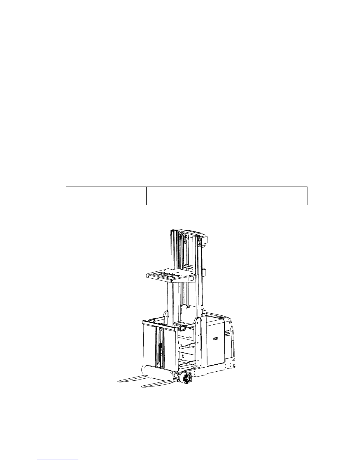
Model Load capacity Load centre
KMS 100 1000 kg 600 mm
B 1
1298.GB
B Truck description
1 Description of application
The commissioner KMS 100 is an industrial truck with powered mechanism according
to DIN 15140. It is operated from the vertically movable driver position and approved
for one operating person.
The load carrying area can always be moved to a convenient working height with the
auxiliary fork lift.
The commissioner is suitable for operation in narrow aisles with racks arranged at the
side. It is especially designed for driving with lifted load.
A perfect floor condition is a prerequisite:
– flat and horizontal floor according to the instructions of the manufacturer of the
commissioner; the floor must be suitable for carrying the weight of the commissio-
ner, the driver and the load during operation
– floor free of foreign matters and parts which might effect the operation or the stabi-
lity of the commissioner
The load capacity is stated on the identification plate.
Model Load capacity Load centre
KMS 100 1000 kg 600 mm
Page 11
1298.GB
B 2
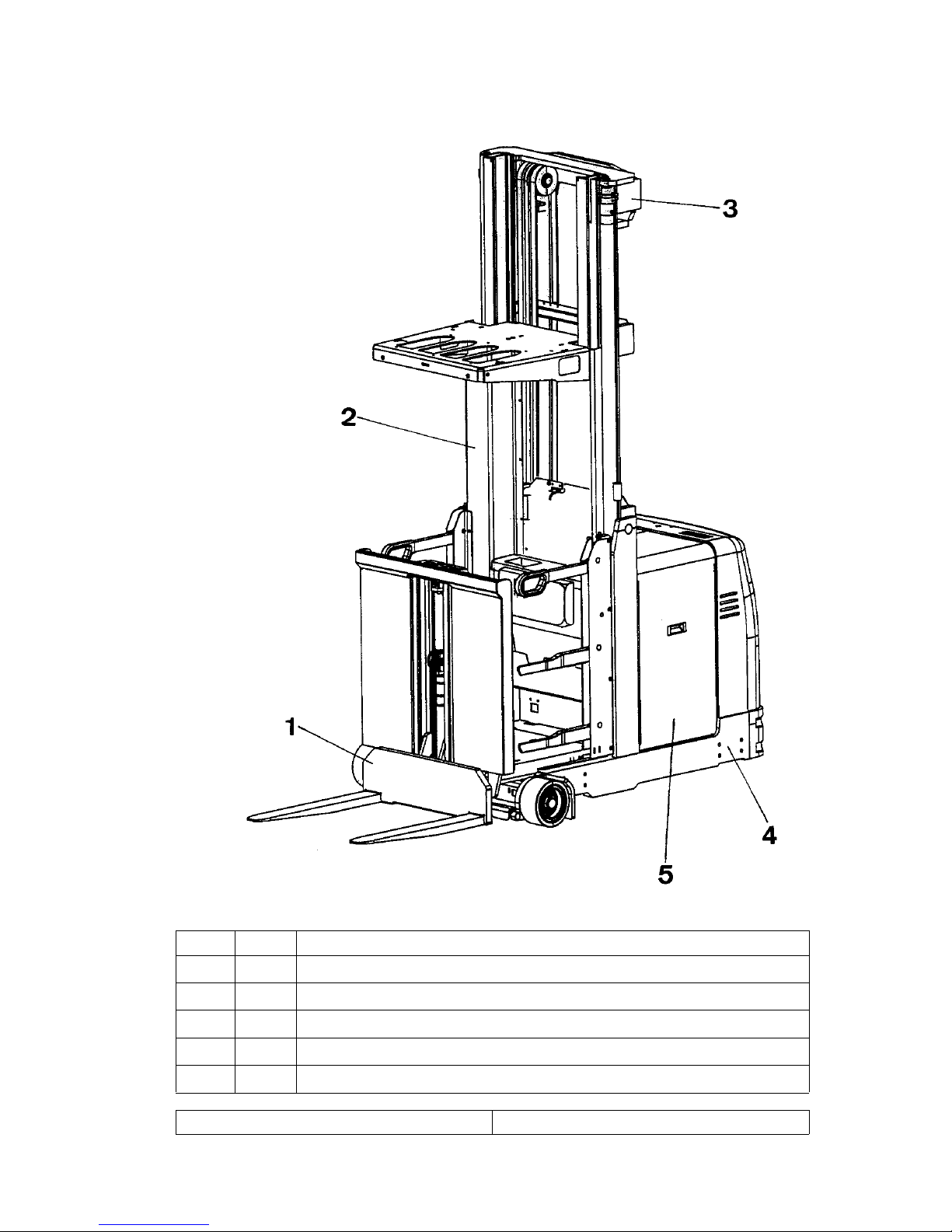
2 Description of assemblies and functions
Pos. Description
1
o
Auxiliary lifter
2
t
Vertically movable operator stand
3
t
Lift mast
4
t
Hoist frame
5
t
Battery
t = Standard equipment o = Optional equipment
1298.GB
B 2
2 Description of assemblies and functions
Pos. Description
1
o
Auxiliary lifter
2
t
Vertically movable operator stand
3
t
Lift mast
4
t
Hoist frame
5
t
Battery
t = Standard equipment o = Optional equipment
Page 12

B 3
1298.GB
2.1 Description of truck
Integrated information display to display all important information to the driver, like
steering wheel position, platform height, truck status signals (e.g. malfunctions, entrance doors open, etc.), operating hours, battery capacity, time as well as status of
the inductive guidance, etc.
Electric steering system with small handy steering handle - steering wheel for precise and easy steering of the compact truck.
Two-hand operation via capacitive sensors at the handle element and master pilot
for relieved hand rest; no uncomfortable operation of dead man's circuits with strain
on the wrists.
Master pilot for simultaneous driving and lifting even if the truck is not operated directly. Functions are operated by natural thumb and hand movements for fatigueless
operation without wrist strain; sensitive adjustment of drive and hydraulic motion for
saving the commissioning goods. Exact driving to the commissioning position as well
as exact positioning of the goods in stacking operation.
Load-side, clear operating panels with a small front part provide
good accessibility of the pallets for a high commissioning capacity. The driver must
never move around to operate the devices and carry out commissioning. Roadway,
load or fork tines are always visible.
Different operating panel arrangement variants (see extras) to adjust the device
operation to the corresponding commissioning goods or the warehouse conditions
Flexibility through variable mounting of the operating panels even if the operating
conditions change.
Arrangement of auxiliary functions (e.g. auxiliary lifter) beside the supporting strap
for efficient and safe device operation without changing the position of the hands. Release and speed control of the auxiliary functions through the master pilot.
Multiple brake system with at least two independently operating systems. Soft and
safe reduction of the truck speed is guaranteed in every situation. Wear-free dynamic
service brake with energy regeneration as well as spring-loaded brake on drive motor
as parking brake during stacking and as emergency stop brake. In due course the vehicles are equipped with an additional hydraulic load wheel brake.
B 3
1298.GB
2.1 Description of truck
Integrated information display to display all important information to the driver, like
steering wheel position, platform height, truck status signals (e.g. malfunctions, ent-
rance doors open, etc.), operating hours, battery capacity, time as well as status of
the inductive guidance, etc.
Electric steering system with small handy steering handle - steering wheel for pre-
cise and easy steering of the compact truck.
Two-hand operation via capacitive sensors at the handle element and master pilot
for relieved hand rest; no uncomfortable operation of dead man's circuits with strain
on the wrists.
Master pilot for simultaneous driving and lifting even if the truck is not operated di-
rectly. Functions are operated by natural thumb and hand movements for fatigueless
operation without wrist strain; sensitive adjustment of drive and hydraulic motion for
saving the commissioning goods. Exact driving to the commissioning position as well
as exact positioning of the goods in stacking operation.
Load-side, clear operating panels with a small front part provide
good accessibility of the pallets for a high commissioning capacity. The driver must
never move around to operate the devices and carry out commissioning. Roadway,
load or fork tines are always visible.
Different operating panel arrangement variants (see extras) to adjust the device
operation to the corresponding commissioning goods or the warehouse conditions
Flexibility through variable mounting of the operating panels even if the operating
conditions change.
Arrangement of auxiliary functions (e.g. auxiliary lifter) beside the supporting strap
for efficient and safe device operation without changing the position of the hands. Re-
lease and speed control of the auxiliary functions through the master pilot.
Multiple brake system with at least two independently operating systems. Soft and
safe reduction of the truck speed is guaranteed in every situation. Wear-free dynamic
service brake with energy regeneration as well as spring-loaded brake on drive motor
as parking brake during stacking and as emergency stop brake. In due course the ve-
hicles are equipped with an additional hydraulic load wheel brake.
Page 13
1298.GB
B 4
3 Technical data of standard version
A
Technical data is stated according to VDI 2198.
Subject to technical changes and supplements.
1298.GB
B 4
3 Technical data of standard version
A
Technical data is stated according to VDI 2198.
Subject to technical changes and supplements.
Page 14

B 5
1298.GB
3.1 General technical data
Identification
1.2 Type index of the manufacturer KMS 100
1.3 Drive electric, diesel, fuel, fuel gas, net electric Electric
1.4
Operation hand, walking, standing, seat, commissioner
Commissioner
1.5 Capacity/load Q (t) 1,0
1.6 Load centre distance c (mm) 600
1.8 Load spacing x (mm) 247
1.9 Wheel base y (mm) 1490
Weights
2.1 Dead weight with battery kg 3430
2.2 Axle load with load front/back kg 3260 / 1170
2.3 Axle load without load front/back kg 1690 / 1740
Wheels, travelling gear
3.1
Tire equipment solid-rubber, superelastic, air,
polyurethane
Tractothane
3.2 Tire size, front d
1
(mm) 230 φ/ 115
3.3 Tire size, back d
2
(mm) 310 φ/ 100
3.5 Wheels, number front/back (x=driven) 2/1x
3.6 Wheel gauge, front b
10
(mm) 895
3.7 Wheel gauge, back b
11
(mm) 0
Electric motor
6.1 Drive motor, capacity S2 60 min kW 4,5
6.2 Lifting motor, capacity at S3 25% kW 9,5
6.3
Battery according to DIN 43531/35/36 A, B, C, no
(max.)
4 PzS 560 A (600)
6.4 Battery voltage, nominal capacity K
5
V/Ah 48
6.5 Weight of battery kg 933
Others
8.1 Type of driving control Impuls/MOSFET
8.4 Sound level, driver's ear dB(A) -
8.6 Steering system electrically
B 5
1298.GB
3.1 General technical data
Identification
1.2 Type index of the manufacturer KMS 100
1.3 Drive electric, diesel, fuel, fuel gas, net electric Electric
1.4
Operation hand, walking, standing, seat, com-
missioner
Commissioner
1.5 Capacity/load Q (t) 1,0
1.6 Load centre distance c (mm) 600
1.8 Load spacing x (mm) 247
1.9 Wheel base y (mm) 1490
Weights
2.1 Dead weight with battery kg 3430
2.2 Axle load with load front/back kg 3260 / 1170
2.3 Axle load without load front/back kg 1690 / 1740
Wheels, travelling gear
3.1
Tire equipment solid-rubber, superelastic, air,
polyurethane
Tractothane
3.2 Tire size, front d
1
(mm) 230 φ/ 115
3.3 Tire size, back d
2
(mm) 310 φ/ 100
3.5 Wheels, number front/back (x=driven) 2/1x
3.6 Wheel gauge, front b
10
(mm) 895
3.7 Wheel gauge, back b
11
(mm) 0
Electric motor
6.1 Drive motor, capacity S2 60 min kW 4,5
6.2 Lifting motor, capacity at S3 25% kW 9,5
6.3
Battery according to DIN 43531/35/36 A, B, C, no
(max.)
4 PzS 560 A (600)
6.4 Battery voltage, nominal capacity K
5
V/Ah 48
6.5 Weight of battery kg 933
Others
8.1 Type of driving control Impuls/MOSFET
8.4 Sound level, driver's ear dB(A) -
8.6 Steering system electrically
Page 15

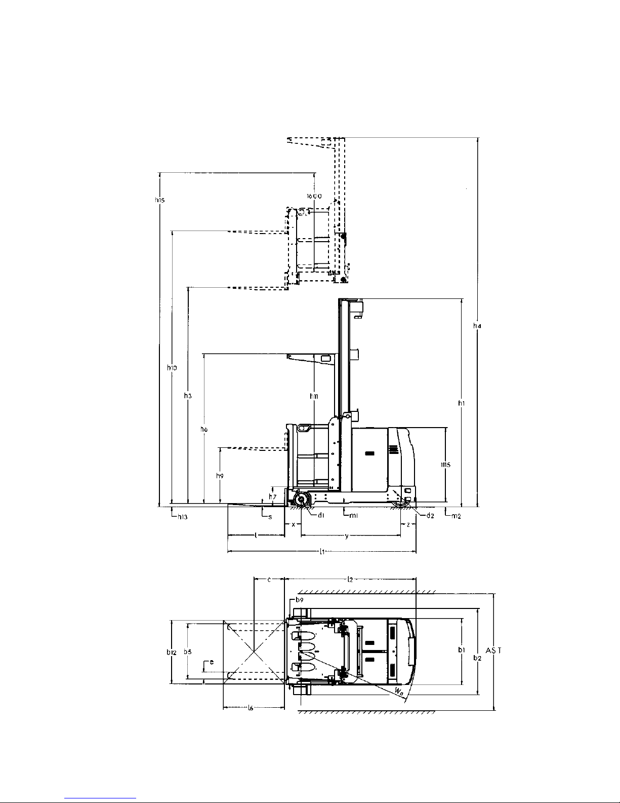
1298.GB
B 6
Basic dimensions
4.2 Height with hoist frame retracted h
1
(mm) 3830
4.3 Free lift h
2
(mm) -
4.4 Length of lift h
3
(mm) 5500
4.5 Height with hoist frame extended h
4
(mm) 7820
4.7 Height above vehicle shed (cabin) h
6
(mm) 2300
4.8 Seating/standing height h
7
(mm) 290
4.11 Auxiliary lifter h
9
(mm) 840
4.12 Total length of lift h
10
(mm) 6340
4.14 Commissioning height h
15
(mm) 7390
4.15 Lowered height h
13
(mm) 70
4.19 Total length without load l
1
(mm) 2870
4.20 Length incl. fork back l
2
(mm) 2070
Distance swivel reach fork pivot L
3
(mm) -
4.21 Total width b
1/b2
(mm) 1010 / 1000
4.22 Fork tine dimensions s/e/l (mm) 40 x 100 x 800
4.23 Fork carrier DIN 15173, class/shape A, B - -
4.24 Fork carrier width b
3
(mm) 830
4.25 Overall distance of fork b
5
(mm) 830
4.27 Width of guide rollers b
6
(mm) 1200
4.29 Reach, sidewards b
7
(mm) -
4.30 Reach, sidewards from the center of the vehicle b
8
(mm) -
4.31 Road clearance with load below hoist frame m
1
(mm) 75
4.32 Ground clearance in wheel base center m
2
(mm) 67
4.33
Working aisle width for pallet
1000 x 1200
sideways
A
st
(mm) 1400
4.34
Working aisle width for pallet
800
x 1200 lengthways
A
st
(mm) 1200
4.35 Turning circle W
a
(mm) 1723
4.36 Pallet width b
12
(mm) 1200
4.37 Pallet length l
6
(mm) 800
4.38 Distance swivel fork pivot l
8
(mm) -
4.39 Cabin depth entrance (mm) 530
4.41 Clear cabin height inside h
11
(mm) 2000
4.42 Driver's seat carrier width outside b
9
(mm) 1200
4.43 Width swivel push frame b
14
(mm) -
4.44 Width jib l
10
(mm) -
Page 16

B 7
1298.GB
3.2 Hoist frame construction
Double telescope (DT) and tripe telescope (TT) hoist frame with complete free lift
Performance data
5.1 Driving speed with / without load km/h 10,0 / 10,5
5.2 Lifting speed with/without load m/s 0,28/0,35
5.3 Lowering speed with / without load m/s 0,40/0,40
5.4 Traverse speed with/without load m/s -
5.7 Hill climbing ability with/without capacity % -
5.8 max. hill-climbing ability with/without load % -
5.9 Acceleration time with/without load s -
5.10 Service brake dynamic
5.11 Parking brake/dead man electr. spring-load
accumulator
Model
Lift
h
3
[mm]
Overall height
retracted
(ZT)
h
1
[mm]
Overall height
retracted
(DZ)
h1 [mm]
Free lift
for DZ
h
2
[mm]
Overall height
extended
h4 [mm]
300 3000 2380 - - 5320
350 3500 2630 2302 - 5820
400 4000 2880 2320 - 6320
450 4500 3130 2320 - 6820
500 5000 3380 2483 163 7320
550 5500 3830 2650 330 7820
600 6000 4080 2816 406 8320
650 6500 4330 3104 784 8820
700 7000 4580 3354 1034 9320
750 7500 4830 3604 1284 9820
800 8000 5080 3854 1534 10320
850 8500 5530 4104 1784 10820
Model
Height above
vehicle shed
h
6
[mm]
Auxiliary
lifter
h9 [mm]
Total
lifting height
h
10
[mm]
Commissioning
height
h
15
[mm]
300 2300 840 3840 4890
350 2300 840 4340 5390
400 2300 840 4840 5890
450 2300 840 5340 6390
500 2300 840 5840 6890
550 2300 840 6340 7390
600 2300 840 6840 7890
650 2300 840 7340 8390
700 2300 840 7840 8890
750 2300 840 8340 9390
800 2300 840 8840 9890
850 2300 840 9340 10390
Page 17

1298.GB
B 8
3.3 EN Standards
Continuous sound level:
65 dB(A)
according to prEN 12053 as stipulated in ISO 4871.
A
The permanent sound level is an average value determined according to the standard’s guidelines and takes into consideration the sound level when driving, lifting
and in idle mode. The sound level is measured at the driver’s ear.
Vibration:
Vibration acceleration in standing position:
1,11 m/s
2
according to document N47E of CEN/TC 150/WG8.
A
The vibration acceleration applied to the operator’s body is measured according the
standard’s guidelines as a linearly integrated, weighted acceleration in vertical direction. The acceleration is measured when driving across bumps at steady speed.
Electromagnetic compatibility (EMC)
The following limit values are observed according to the
product standards “Electromagnetic Compatibility of Industrial Trucks (9/95)“:
- interference emission (EN 50081-1)
- interference immunity (EN 50082-2)
- electrostatic discharge (EN 61000-4-2).
A
Electrical or electronic components and their arrangement may only be modified after
written approval by the manufacturer has been obtained.
3.4 Operation conditions
Environmental temperature
– in operation 0°C bis + 40°C.
1298.GB
B 8
3.3 EN Standards
Continuous sound level:
65 dB(A)
according to prEN 12053 as stipulated in ISO 4871.
A
The permanent sound level is an average value determined according to the stan-
dard’s guidelines and takes into consideration the sound level when driving, lifting
and in idle mode. The sound level is measured at the driver’s ear.
Vibration:
Vibration acceleration in standing position:
1,11 m/s
2
according to document N47E of CEN/TC 150/WG8.
A
The vibration acceleration applied to the operator’s body is measured according the
standard’s guidelines as a linearly integrated, weighted acceleration in vertical direc-
tion. The acceleration is measured when driving across bumps at steady speed.
Electromagnetic compatibility (EMC)
The following limit values are observed according to the
product standards “Electromagnetic Compatibility of In-
dustrial Trucks (9/95)“:
- interference emission (EN 50081-1)
- interference immunity (EN 50082-2)
- electrostatic discharge (EN 61000-4-2).
A
Electrical or electronic components and their arrangement may only be modified after
written approval by the manufacturer has been obtained.
3.4 Operation conditions
Environmental temperature
– in operation 0°C bis + 40°C.
Page 18
B 9
1298.GB
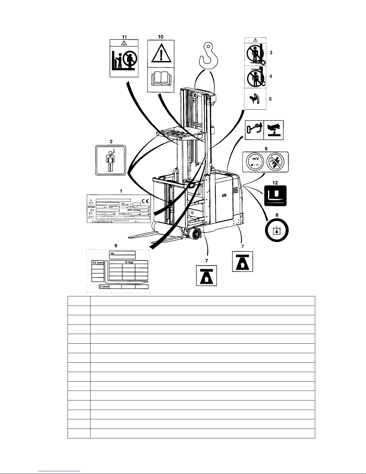
4 Location of instruction labels and identification labels
Pos. Description
1 Truck identification label
2 Sign “Emergency lowering device”
3 Warning sign “Lifting of persons prohibited”
4 Warning sign “Keep away from under the load lifting device”
5 Warning sign “Danger of crushing”
6 Warning sign “Caution: Low-voltage electronics”
7 Attachment point for jack
8 Fill in hydraulic oil
9 Capacity plate
10 Sign “Read operating instructions”
11 Prohibitive sign “Do not travel on load lifting device”
12 Emergency outlet
13 Sign for opening and closing the hood
14 Pick-up points for crane transportation
B 9
1298.GB
4 Location of instruction labels and identification labels
Pos. Description
1 Truck identification label
2 Sign “Emergency lowering device”
3 Warning sign “Lifting of persons prohibited”
4 Warning sign “Keep away from under the load lifting device”
5 Warning sign “Danger of crushing”
6 Warning sign “Caution: Low-voltage electronics”
7 Attachment point for jack
8 Fill in hydraulic oil
9 Capacity plate
10 Sign “Read operating instructions”
11 Prohibitive sign “Do not travel on load lifting device”
12 Emergency outlet
13 Sign for opening and closing the hood
14 Pick-up points for crane transportation
Page 19
1298.GB
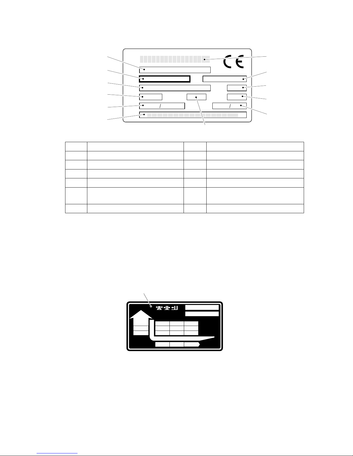
B 10
4.1 Truck identification label
In the event of queries relating to the truck or spare part orders, please state the serial
no. (19) of the truck.
4.2 Load capacity
The label (12) shows a table with the capacity Q of the truck in relation to the load
center distance (D in mm) and the lifting height (H in mm).
Pos. Description Pos. Description
18 Model 24 Load centre distance in mm
19 Serial no. 25 Min./max. battery weight in kg
20 Order no. 26 Net weight without battery in kg
21 Capacity in kg 27 Year of manufacture
22 Battery: voltage V
Ampere hours Ah
28 Type no.
23 Maker 29 Maker’s logotype
X xx xx
xxxx xx
Xxx
Xxxx
Xxxx
Xxxx
Xxxxxxx
Xxxxxx
Xxxxxxxx
Xxxxxx
Xxxxxx
Xxxxxxxxx
Xxxxxxxxxx
Xxxxxxxxx
Xxxxxxxxx
Xxxxx
Xxxxx
Xxxxx
Xxxxx
Xxxxxxx
Xxxxxxxxxx
Xxxxxx
Xxxxxxxxx
Xxxxxx
Xxxxxx
Xxxxxxx
Xxxxxx
Xxxxxx
Xxxxxxxxxxxxxx
Xxxxxxxxxxxxxxx
Xxxxxxx
Xxxxxxxxxxxxxxxxxxxx
Xxxxxxxxxxxxxxxxxxxxx
Xxxxxxxxxxxxxxxxxxx
Xxxxxxxxxxxxxxxxxxxx
Xxxxxxxxxxxxxxxxxxx
Xxxxxxxxxxxxxxxxx
Xxxxxxxxxxxxxxxxxxxxxxxxx
Xxxxxxxxxxxxxxxxxx
Xxxxxxxxxxxxxxxxxx
Xxxxxxxxxxxxxxxxxx
Xxxxxxxxxxxxxxxxxxxxxx
Xxxxxxxxxxxxxxxxxx
Xx
18
19
20
21
22
24
28
29
27
26
25
23
-Nr.
Serien-Nr.
Dmm
Hmm
Qkg
12
1298.GB
B 10
4.1 Truck identification label
In the event of queries relating to the truck or spare part orders, please state the serial
no. (19) of the truck.
4.2 Load capacity
The label (12) shows a table with the capacity Q of the truck in relation to the load
center distance (D in mm) and the lifting height (H in mm).
Pos. Description Pos. Description
18 Model 24 Load centre distance in mm
19 Serial no. 25 Min./max. battery weight in kg
20 Order no. 26 Net weight without battery in kg
21 Capacity in kg 27 Year of manufacture
22 Battery: voltage V
Ampere hours Ah
28 Type no.
23 Maker 29 Maker’s logotype
X xx xx
xxxx xx
Xxx
Xxxx
Xxxx
Xxxx
Xxxxxxx
Xxxxxx
Xxxxxxxx
Xxxxxx
Xxxxxx
Xxxxxxxxx
Xxxxxxxxxx
Xxxxxxxxx
Xxxxxxxxx
Xxxxx
Xxxxx
Xxxxx
Xxxxx
Xxxxxxx
Xxxxxxxxxx
Xxxxxx
Xxxxxxxxx
Xxxxxx
Xxxxxx
Xxxxxxx
Xxxxxx
Xxxxxx
Xxxxxxxxxxxxxx
Xxxxxxxxxxxxxxx
Xxxxxxx
Xxxxxxxxxxxxxxxxxxxx
Xxxxxxxxxxxxxxxxxxxxx
Xxxxxxxxxxxxxxxxxxx
Xxxxxxxxxxxxxxxxxxxx
Xxxxxxxxxxxxxxxxxxx
Xxxxxxxxxxxxxxxxx
Xxxxxxxxxxxxxxxxxxxxxxxxx
Xxxxxxxxxxxxxxxxxx
Xxxxxxxxxxxxxxxxxx
Xxxxxxxxxxxxxxxxxx
Xxxxxxxxxxxxxxxxxxxxxx
Xxxxxxxxxxxxxxxxxx
Xx
18
19
20
21
22
24
28
29
27
26
25
23
-Nr.
Serien-Nr.
Dmm
Hmm
Qkg
12
Page 20
C 1
1298.GB
C Transportation and commissioning
1 Transport
Depending on the overall height of the hoist frame and local conditions the on-site
transport can be carried out in one of three different ways:
– Standing, with hoist frame and load lifting device mounted
(for low height versions)
– Standing, with tilted hoist frame and dismounted load lifting device, resting on
transport frame
– Standing, with hoist frame and load lifting device dismounted
(for tall versions)
m
On-site assembly of the truck, commissioning, and instructing of operator must be
carried out by trained personnel of the manufacturer. Transport regulations and erection instructions must be observed!
2 Transportation by crane
m
Ensure that only lifting gear of adequate capacity is used (for weight of the truck refer
to the truck identification label. See chapter B).
– Park the truck and render it safe (refer to
chapter E).
– If the mast is mounted, the crane points
are at the top of the mast crosshead.
– If the mast is tilted, the lifting gear must
be mounted at the top of the mast crosshead and at the crosshead on the bottom of the mast.
– If the truck is to be lifted by crane with til-
ted mast, the transportation parts must
be mounted.
m
Secure the hoisting gear to the hoisting
points (1) ensuring that the hoisting gear
will not slip!
1
1
C 1
1298.GB
C Transportation and commissioning
1 Transport
Depending on the overall height of the hoist frame and local conditions the on-site
transport can be carried out in one of three different ways:
– Standing, with hoist frame and load lifting device mounted
(for low height versions)
– Standing, with tilted hoist frame and dismounted load lifting device, resting on
transport frame
– Standing, with hoist frame and load lifting device dismounted
(for tall versions)
m
On-site assembly of the truck, commissioning, and instructing of operator must be
carried out by trained personnel of the manufacturer. Transport regulations and erec-
tion instructions must be observed!
2 Transportation by crane
m
Ensure that only lifting gear of adequate capacity is used (for weight of the truck refer
to the truck identification label. See chapter B).
– Park the truck and render it safe (refer to
chapter E).
– If the mast is mounted, the crane points
are at the top of the mast crosshead.
– If the mast is tilted, the lifting gear must
be mounted at the top of the mast cros-
shead and at the crosshead on the bot-
tom of the mast.
– If the truck is to be lifted by crane with til-
ted mast, the transportation parts must
be mounted.
m
Secure the hoisting gear to the hoisting
points (1) ensuring that the hoisting gear
will not slip!
1
1
Page 21
1298.GB
C 2
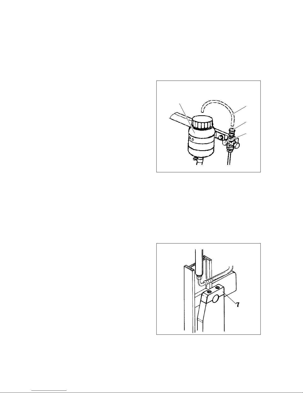
3 First commissioning
3.1 Commissioning without battery
m
This operating mode is not permitted when negotiating inclines and gradients (no brake!).
A
If the truck is operated without battery, the load bearing wheel brake must be released
before commissioning.
– Screw off the protective cover (5) of
the vent valve.
– Push tube (4) onto vent connection
and insert the other end of the tube
into the brake fluid reservoir (3) located above.
f
Brake fluid is under pressure.
Danger of causticization.
– Open vent valve (6) and allow emer-
ging brake fluid to drain into the brake
fluid reservoir.
– Close vent valve and brake fluid re-
servoir.
A
The operatability of the brake system is restored after inserting the battery and after
operating the foot switch several times.
m
Test the brake deceleration.
These measures may only be performed by service engineers of the manufacturer.
3.2 Commissioning with dismounted or tilted mast
If the truck has been delivered with dismounted or tilted mast due to tall height, the
mast has to be mounted by a trained mechanic.
– If mast is tilted, loosen lift mast pede-
stal (7) (do not remove screws).
– Set hoist frame with suitable hoisting
equipment to a vertical position. Add
compensating sheets, if available,
and screw down mast and lifting mast
bearing.
3
4
5
6
1298.GB
C 2
3 First commissioning
3.1 Commissioning without battery
m
This operating mode is not permitted when negotiating inclines and gradients (no bra-
ke!).
A
If the truck is operated without battery, the load bearing wheel brake must be released
before commissioning.
– Screw off the protective cover (5) of
the vent valve.
– Push tube (4) onto vent connection
and insert the other end of the tube
into the brake fluid reservoir (3) loca-
ted above.
f
Brake fluid is under pressure.
Danger of causticization.
– Open vent valve (6) and allow emer-
ging brake fluid to drain into the brake
fluid reservoir.
– Close vent valve and brake fluid re-
servoir.
A
The operatability of the brake system is restored after inserting the battery and after
operating the foot switch several times.
m
Test the brake deceleration.
These measures may only be performed by service engineers of the manufacturer.
3.2 Commissioning with dismounted or tilted mast
If the truck has been delivered with dismounted or tilted mast due to tall height, the
mast has to be mounted by a trained mechanic.
– If mast is tilted, loosen lift mast pede-
stal (7) (do not remove screws).
– Set hoist frame with suitable hoisting
equipment to a vertical position. Add
compensating sheets, if available,
and screw down mast and lifting mast
bearing.
3
4
5
6
Page 22

C 3
1298.GB
4 Commissioning
m
The truck must only be operated on battery current. Rectified alternate current will damage the electronics. Cables connected to the battery (towing cable) must be less
than 6 meters in length.
In order to prepare the truck for work following delivery or transportation, the following
operations must be performed:
– If necessary, install and charge the battery (see chapter D, sections 4 and 5).
– Commission the truck as detailed in chapter E, section 3.
m
Please check if the tilting protection (1) is
existing before commissioning the
trucks.
All safety devices must be checked on
their availability and function.
1
1
C 3
1298.GB
4 Commissioning
m
The truck must only be operated on battery current. Rectified alternate current will da-
mage the electronics. Cables connected to the battery (towing cable) must be less
than 6 meters in length.
In order to prepare the truck for work following delivery or transportation, the following
operations must be performed:
– If necessary, install and charge the battery (see chapter D, sections 4 and 5).
– Commission the truck as detailed in chapter E, section 3.
m
Please check if the tilting protection (1) is
existing before commissioning the
trucks.
All safety devices must be checked on
their availability and function.
1
1
Page 23

1298.GB
C 4
1298.GB
C 4
Page 24

D 1
1298.GB
D Battery - servicing, recharging, replacing
1 Safety regulations governing the handling of lead-acid batteries
The truck must be parked and rendered safe before any operations on batteries are
to be undertaken (refer to chapter E).
Servicing staff: Recharging, servicing and replacing of batteries must only be performed by qualified personnel. The instructions contained in this operating manual,
and the instructions as prepared by the battery supplier and as available at the battery
recharging station must be observed, when performing the above operations.
Fire protection measures: Smoking and naked flames are not permitted when
handling batteries. No inflammable substances or spark-generating materials must
be present or stored within a distance of 2 meters of the truck parked for battery recharging. The location must be well ventilated. Fire fighting equipment must be kept
ready.
Servicing of batteries: The battery cell screw caps must be kept dry and clean. Terminals and cable shoes must be clean, lightly greased with pole grease and must be
securely tightened.
Disposal of the battery: Batteries must only be disposed of as stipulated in the national environmental protection regulations or waste disposal provisions. The manufacturer’s specifications for the disposal must be heeded.
m
Before closing the battery hood, make sure that the battery cable cannot be damaged.
f
Batteries contain dissolved acid, which is toxic and caustic. For this reason protective
clothing and goggles must be worn whenever work is undertaken on batteries. Avoid
physical contact with battery acid. If clothing, skin or eyes have accidentally come into
contact with battery acid, liberally flush the affected parts with clean water. Consult a
doctor, when skin or eyes have come into contact with battery acid. Spilled battery
acid must be immediately neutralised.
2 Battery types
Depending on their application, the WK truck is equipped different with battery types.
All battery types are approved according to DIN 43531-A. The following table shows
the standard battery combinations and battery capacities:
The battery weights can be seen from the battery identification plates.
f
Battery weight and dimensions have a considerable influence on the stability of the
truck. Therefore, a change of the battery type is only permitted with the prior consent
of the truck manufacturer.
Battery type Truck type
48V 560 AH KMS 100
48V 600 AH KMS 100
D 1
1298.GB
D Battery - servicing, recharging, replacing
1 Safety regulations governing the handling of lead-acid batteries
The truck must be parked and rendered safe before any operations on batteries are
to be undertaken (refer to chapter E).
Servicing staff: Recharging, servicing and replacing of batteries must only be per-
formed by qualified personnel. The instructions contained in this operating manual,
and the instructions as prepared by the battery supplier and as available at the battery
recharging station must be observed, when performing the above operations.
Fire protection measures: Smoking and naked flames are not permitted when
handling batteries. No inflammable substances or spark-generating materials must
be present or stored within a distance of 2 meters of the truck parked for battery re-
charging. The location must be well ventilated. Fire fighting equipment must be kept
ready.
Servicing of batteries: The battery cell screw caps must be kept dry and clean. Ter-
minals and cable shoes must be clean, lightly greased with pole grease and must be
securely tightened.
Disposal of the battery: Batteries must only be disposed of as stipulated in the na-
tional environmental protection regulations or waste disposal provisions. The manu-
facturer’s specifications for the disposal must be heeded.
m
Before closing the battery hood, make sure that the battery cable cannot be dama-
ged.
f
Batteries contain dissolved acid, which is toxic and caustic. For this reason protective
clothing and goggles must be worn whenever work is undertaken on batteries. Avoid
physical contact with battery acid. If clothing, skin or eyes have accidentally come into
contact with battery acid, liberally flush the affected parts with clean water. Consult a
doctor, when skin or eyes have come into contact with battery acid. Spilled battery
acid must be immediately neutralised.
2 Battery types
Depending on their application, the WK truck is equipped different with battery types.
All battery types are approved according to DIN 43531-A. The following table shows
the standard battery combinations and battery capacities:
The battery weights can be seen from the battery identification plates.
f
Battery weight and dimensions have a considerable influence on the stability of the
truck. Therefore, a change of the battery type is only permitted with the prior consent
of the truck manufacturer.
Battery type Truck type
48V 560 AH KMS 100
48V 600 AH KMS 100
Page 25

1298.GB
D 2
3 Charging the battery
f
Park the truck and render it safe (see chapter E).
– Turn the key switch to “0” (Zero) and push the Emergency stop switch.
– Lift the battery hood to its full extent.
f
The battery connector and socket must only be connected or disconnected with both
the truck and the battery charger switched off.
– Withdraw the battery connector.
– Remove any insulating matting from the batteries.
f
During the recharging operation the tops of the battery cells must be exposed to ensure adequate ventilation. Metal objects must not be placed on the battery. Prior to
starting the recharging operation, check all cable connections and plugged connections for visible damage.
– Connect the charging cable of the battery charger to the battery connector.
– Switch on the battery charger.
– Recharge the battery observing the instructions provided by the battery supplier
and by the battery charger supplier.
f
All safety instructions as provided by the battery supplier and battery charger supplier
must be strictly observed.
1298.GB
D 2
3 Charging the battery
f
Park the truck and render it safe (see chapter E).
– Turn the key switch to “0” (Zero) and push the Emergency stop switch.
– Lift the battery hood to its full extent.
f
The battery connector and socket must only be connected or disconnected with both
the truck and the battery charger switched off.
– Withdraw the battery connector.
– Remove any insulating matting from the batteries.
f
During the recharging operation the tops of the battery cells must be exposed to en-
sure adequate ventilation. Metal objects must not be placed on the battery. Prior to
starting the recharging operation, check all cable connections and plugged connec-
tions for visible damage.
– Connect the charging cable of the battery charger to the battery connector.
– Switch on the battery charger.
– Recharge the battery observing the instructions provided by the battery supplier
and by the battery charger supplier.
f
All safety instructions as provided by the battery supplier and battery charger supplier
must be strictly observed.
Page 26

D 3
1298.GB
4 Removing and installing the battery
f
Batteries with exposed terminals or connectors must be covered with a rubber mat to
prevent short-circuits.
f
When replacing batteries, ensure that a battery of the same type is fitted. Additional
weights must not be removed and their position must not be changed.
– Turn the key switch to “0” (Zero) and push the emergency stop switch.
– Lift the battery hood to its full extent.
f
The battery connector and socket must only be connected or disconnected with both
the truck and the battery charger switched off.
– Withdraw the battery connector.
– Lift out the chassis lateral part.
4.1 Removing and installing using a battery trolly
f
The vehicle must be on level ground, to prevent accidental movement of the battery
after loosening the battery safety device.
– Release the battery safety device.
– Pull the battery laterally onto a battery trolley.
Installation is in the reverse order.
f
Following reinstallation of the battery, visually check all leads and connectors for damage and prior to the recommissioning of the truck check
– that the battery safety device is tightened again,
– that the battery hood is safely locked.
D 3
1298.GB
4 Removing and installing the battery
f
Batteries with exposed terminals or connectors must be covered with a rubber mat to
prevent short-circuits.
f
When replacing batteries, ensure that a battery of the same type is fitted. Additional
weights must not be removed and their position must not be changed.
– Turn the key switch to “0” (Zero) and push the emergency stop switch.
– Lift the battery hood to its full extent.
f
The battery connector and socket must only be connected or disconnected with both
the truck and the battery charger switched off.
– Withdraw the battery connector.
– Lift out the chassis lateral part.
4.1 Removing and installing using a battery trolly
f
The vehicle must be on level ground, to prevent accidental movement of the battery
after loosening the battery safety device.
– Release the battery safety device.
– Pull the battery laterally onto a battery trolley.
Installation is in the reverse order.
f
Following reinstallation of the battery, visually check all leads and connectors for da-
mage and prior to the recommissioning of the truck check
– that the battery safety device is tightened again,
– that the battery hood is safely locked.
Page 27

1298.GB
D 4
5 Checking battery condition, acid level, and acid density
– The service instructions of the battery supplier apply.
– Check the battery casing for cracks and acid leaks.
– Remove oxidation residues from the battery terminals and lightly grease with acid-
free pole grease.
– Screw out the screw caps and check the acid level.
The acid level must be a minimum of 10-15mm above the plate top.
– Check the acid density according to the suppliers specifications with an acid pipette
and subsequently remount the screw caps.
– If necessary, recharge the battery.
6 Battery discharge indicator
After turning the key in the key-operated
switch to the right and pulling the emergency stop switch, the battery discharge
indicator steplessly displays the remaining capacity. The indicator is flashing at
a remaining capacity of 30 %. If the capacity indication falls below 20 %, the lifting unit is switched off.
+-
50%
1298.GB
D 4
5 Checking battery condition, acid level, and acid density
– The service instructions of the battery supplier apply.
– Check the battery casing for cracks and acid leaks.
– Remove oxidation residues from the battery terminals and lightly grease with acid-
free pole grease.
– Screw out the screw caps and check the acid level.
The acid level must be a minimum of 10-15mm above the plate top.
– Check the acid density according to the suppliers specifications with an acid pipette
and subsequently remount the screw caps.
– If necessary, recharge the battery.
6 Battery discharge indicator
After turning the key in the key-operated
switch to the right and pulling the emer-
gency stop switch, the battery discharge
indicator steplessly displays the remai-
ning capacity. The indicator is flashing at
a remaining capacity of 30 %. If the ca-
pacity indication falls below 20 %, the lif-
ting unit is switched off.
+-
50%
Page 28

E 1
1298.GB
E Operation
1 Safety regulations governing the operation of the truck
Driving licence: The truck must only be operated by personnel that have been ade-
quately trained and have proved to the persons in charge or their representatives
their ability to handle the truck correctly and who have been explicitly entrusted with
the operation of the truck.
Rights, obligations and behavioural rules for the driver: The driver must have
been informed about his rights and duties, must have been trained in the operation of
the truck and must be familiar with these operating instructions. All necessary rights
must be granted to him.
If the floor conveyor is to be accompanied by a second person, it is required to wear
protective shoes.
Operation through unauthorised persons is prohibited: The driver is responsible
for his truck during working time. He must forbid unauthorised persons to drive or operate the truck. The transport or lifting of persons is forbidden.
Damages and defects: Damage or defects noted on the truck or on the attachments
must immediately be brought to the notice of the person in charge. Trucks that cannot
be safely operated (e.g. due to worn tires or defective brakes) must not be used until
they have been properly repaired.
Repairs: Without specific training and express authorisation the driver is not allowed
to perform any repairs or modifications on the truck. Under no circumstances must
the driver change the setting of switches or safety installations, or render them ineffective.
Danger zone: The danger zone is that area in which persons are endangered by driving or lifting movements of the floor conveyor, its load lifting devices (e.g. fork or attachments) or the load. Also the area in which the load may fall down or in which a
operating device may be lowered or fall down belongs to this area.
f
Unauthorised persons must be told to leave the danger area. The driver must give a
warning signal, whenever a situation presenting danger to persons might develop.
The truck must immediately be brought to a standstill, if persons, although asked, do
not leave the danger area.
Safety devices and warning labels: The safety devices, warning labels and warning
notes described in the present operating instructions must always be heeded.
E 1
1298.GB
E Operation
1 Safety regulations governing the operation of the truck
Driving licence: The truck must only be operated by personnel that have been ade-
quately trained and have proved to the persons in charge or their representatives
their ability to handle the truck correctly and who have been explicitly entrusted with
the operation of the truck.
Rights, obligations and behavioural rules for the driver: The driver must have
been informed about his rights and duties, must have been trained in the operation of
the truck and must be familiar with these operating instructions. All necessary rights
must be granted to him.
If the floor conveyor is to be accompanied by a second person, it is required to wear
protective shoes.
Operation through unauthorised persons is prohibited: The driver is responsible
for his truck during working time. He must forbid unauthorised persons to drive or ope-
rate the truck. The transport or lifting of persons is forbidden.
Damages and defects: Damage or defects noted on the truck or on the attachments
must immediately be brought to the notice of the person in charge. Trucks that cannot
be safely operated (e.g. due to worn tires or defective brakes) must not be used until
they have been properly repaired.
Repairs: Without specific training and express authorisation the driver is not allowed
to perform any repairs or modifications on the truck. Under no circumstances must
the driver change the setting of switches or safety installations, or render them inef-
fective.
Danger zone: The danger zone is that area in which persons are endangered by dri-
ving or lifting movements of the floor conveyor, its load lifting devices (e.g. fork or at-
tachments) or the load. Also the area in which the load may fall down or in which a
operating device may be lowered or fall down belongs to this area.
f
Unauthorised persons must be told to leave the danger area. The driver must give a
warning signal, whenever a situation presenting danger to persons might develop.
The truck must immediately be brought to a standstill, if persons, although asked, do
not leave the danger area.
Safety devices and warning labels: The safety devices, warning labels and warning
notes described in the present operating instructions must always be heeded.
Page 29

1298.GB
E 2
2 Operating panel arrangement variants
Variant I
In case of standard equipment the operating
panels are arranged at the front, i.e. in front of
the auxiliary lifter. Accordingly the information
display under the driver's overhead guard is
also arranged in load direction.
Variant II
The operating panel and the information display are arranged at the mast side. The information display is arranged under the driver's
overhead guard.
Variant III
The operating controls are arranged diagonally. The driver is looking to the left in load direction.
The operating panel module "stearing" is arranged at the mast side and the "master pilot"
is arranged at the load side. The information
display is located at the load side under the
overhead guard of the driver. The auxiliary lifter is operated at the load side.
1298.GB
E 2
2 Operating panel arrangement variants
Variant I
In case of standard equipment the operating
panels are arranged at the front, i.e. in front of
the auxiliary lifter. Accordingly the information
display under the driver's overhead guard is
also arranged in load direction.
Variant II
The operating panel and the information dis-
play are arranged at the mast side. The infor-
mation display is arranged under the driver's
overhead guard.
Variant III
The operating controls are arranged diagonal-
ly. The driver is looking to the left in load direc-
tion.
The operating panel module "stearing" is ar-
ranged at the mast side and the "master pilot"
is arranged at the load side. The information
display is located at the load side under the
overhead guard of the driver. The auxiliary lif-
ter is operated at the load side.
Page 30

E 3
1298.GB
Variant IV
The operating controls are arranged at the
load side and diagonally. The driver is directly
or diagonally looking to the left in load direction. The operating panel module "stearing" is
additionally available at the mast side. The information display is located at the load side
under the overhead guard of the driver.
The auxiliary lifter is operated at the load side.
Variant V
The operating controls are arranged at the
mast side and diagonally. The driver is directly
or diagonally looking to the left in mast direction. The operating panel module "stearing" is
additionally available at the load side. The information display is located at the mast side
under the overhead guard of the driver.
The auxiliary lifter is operated at the load side.
Variant VI
Double arrangement of operating controls in
load and mast direction. The information display is arranged at the load or at the mast side.
The auxiliary lifter is operated at the load and
at the mast side.
E 3
1298.GB
Variant IV
The operating controls are arranged at the
load side and diagonally. The driver is directly
or diagonally looking to the left in load direc-
tion. The operating panel module "stearing" is
additionally available at the mast side. The in-
formation display is located at the load side
under the overhead guard of the driver.
The auxiliary lifter is operated at the load side.
Variant V
The operating controls are arranged at the
mast side and diagonally. The driver is directly
or diagonally looking to the left in mast direc-
tion. The operating panel module "stearing" is
additionally available at the load side. The in-
formation display is located at the mast side
under the overhead guard of the driver.
The auxiliary lifter is operated at the load side.
Variant VI
Double arrangement of operating controls in
load and mast direction. The information dis-
play is arranged at the load or at the mast si-
de.
The auxiliary lifter is operated at the load and
at the mast side.
Page 31

1298.GB
E 4
3 Description of controls and indicating instruments
3.1 Operating controls and displays at the instrument panel
Pos. Function
1 Emergency stop master switch
2 Steering
3 Supporting strap (two-hand operation)
4 "Pushbutton“ lift switch-off
5 "Pushbutton“ track guidance = drive wheel in straight forward position
induction guide = induction guide on
6 Drive control knob
7Horn
8 Hydraulic control knob (two-hand operation)
9 Key switch
10 Optional function keys
10
Page 32

E 5
1298.GB
3.2 Operating controls and indications at the Display
Pos. Operating control
resp. display
Function
12 Display “Crawling pace” t Drive is switched to crawling pace
13 Steering position indicator t
RG
IG
Indicates the current position of the drive
wheel referring to neutral position
Aisle recognition
track-in possible, track-in in progress, vehic-
le on track
14 Indication "main lift“ t Indicates the height of the cabin
15 Display “Operating hours” t Indicates the operating hours since commis-
sioning
16 Display “Time” t Indicates the time of day
17 Battery discharge indica-
tor
t Indicates the charging condition of the batte-
ry
18 Display “Parking brake
on”
t Illuminates, when the parking brake is enga-
ged
19 Display “Emergency-
STOP”
t Illuminates, when the Emergency-STOP has
been activated
20 Display “Service required/
malfunction”
t Illuminates, when a service action is required
or a malfunction has occurred
21 Slack-chain safety device
display
t Indicates that the slack-chain safety device
has responded
24 Display “Induction guide
on”
RGIGIndicates the straight forward position of the
drive wheel
Indicates that the induction guide is active
26 Display “
“Lift switch-off inactive“
o Indicates that the automatic lift switch-off has
been deactivated
28 Display “Synchronous
turning right”
t Indicates that the function “Synchronous
turning right” has been activated
t = Standard equipment o = Optional equipment
RG = rail guide IG = induction guide
Page 33

1298.GB
E 6
3.3 Symbols indicating the truck’s operating status
After switching on the truck’s operating status is indicated in the display.
Barriers open
Foot-operated switch not activated
If the following symbols are displayed, a reference run must be carried out according
to the indication, i.e. the main lift must be lifted by approx. 30 cm and lowered again.
Then the control gives a release to carry out all movements of the truck with full
speed.
Reference run: Lift main lifter
Reference run: Lower main lifter
Page 34

E 7
1298.GB
4 Putting vehicle in operation
f
Before starting or operating the truck, or before lifting any loads, the driver has to
make sure that nobody is within the danger area.
Checks and actions before routine start-up
– Perform a visual check of the entire truck for obvious damages or leakages.
– Check the battery attachment and the cable connections for damages and tight se-
at.
– Check the battery connector for tight seat.
– Check the overhead guard for damages.
– Check the load lifting device for obvious damages such as cracks, bent or heavily
abrased fork.
– Check the load bearing wheels for damages.
– Check whether the load chains are tightened evenly.
– Check whether all safety measures are in good condition and working properly.
– In case of a rail guide, check idler pulleys on true running and damages.
– Check brakes for correct function.
f
Only one person is allowed in the driver’s cabin!
Provide operatability
f
When closing or opening the cabin lock
between barrier and frame, take care not
to pinch your fingers.
– Fully close the safety barriers on both
sides.
– Insert key into the key switch (3) and
turn clockwise.
– Turn the Emergency-OFF switch (2) to
unlock it.
– Check the warning signal (horn) for
correct function.
– Check the service brake and parking
brake for correct function.
– Carry out reference run of the lifting
mast to adjust height indication and
maximum movements.
f
If during start-up procedure any unwanted driving or lifting movements are observed, immediately operate the
Emergency-OFF switch.
3
E 7
1298.GB
4 Putting vehicle in operation
f
Before starting or operating the truck, or before lifting any loads, the driver has to
make sure that nobody is within the danger area.
Checks and actions before routine start-up
– Perform a visual check of the entire truck for obvious damages or leakages.
– Check the battery attachment and the cable connections for damages and tight se-
at.
– Check the battery connector for tight seat.
– Check the overhead guard for damages.
– Check the load lifting device for obvious damages such as cracks, bent or heavily
abrased fork.
– Check the load bearing wheels for damages.
– Check whether the load chains are tightened evenly.
– Check whether all safety measures are in good condition and working properly.
– In case of a rail guide, check idler pulleys on true running and damages.
– Check brakes for correct function.
f
Only one person is allowed in the driver’s cabin!
Provide operatability
f
When closing or opening the cabin lock
between barrier and frame, take care not
to pinch your fingers.
– Fully close the safety barriers on both
sides.
– Insert key into the key switch (3) and
turn clockwise.
– Turn the Emergency-OFF switch (2) to
unlock it.
– Check the warning signal (horn) for
correct function.
– Check the service brake and parking
brake for correct function.
– Carry out reference run of the lifting
mast to adjust height indication and
maximum movements.
f
If during start-up procedure any unwan-
ted driving or lifting movements are ob-
served, immediately operate the
Emergency-OFF switch.
3
Page 35

1298.GB
E 8
5 Working with the truck
5.4 Safety regulations for operating mode Drive
Routes and working areas: Only such lanes and routes that are specially allocated
for truck traffic may be used. Unauthorised third parties must stay away from the working area. Loads may only be stored at places specially provided for this purpose.
Driving the vehicle: The driver must choose a driving speed suitable for the local
conditions. The truck must be driven at slow speed when negotiating bends or narrow
passages, when passing through swing doors and at blind spots. The driver must always observe an adequate braking distance between his truck and the vehicle in front
and he must be in control of his truck at all times. Sudden stopping (except in emergencies), rapid U-turns and overtaking at dangerous or blind spots is not permitted.
Visibility during driving: The driver must look into the driving direction and have a
sufficient overview of the driving route. When loads that obstruct the clear view are
transported, the truck must travel with the load at the rear. If this is not possible, a
second person must give suitable warnings.
Driving on slopes: It is not allowed to drive on ascending and decending gradients!
Driving in lifts or on loading platforms: Lifts and loading platforms must only be
used, if they are of adequate load bearing capacity, if suitable for driving on, and if
authorised by the user of the truck for truck traffic. The truck must enter lifts with the
load in front and must take up a position which does not allow it to come into contact
with the walls of the lift shaft.
Persons riding in the lift together with the truck must only enter the lift after the truck
has come safely to a standstill, and must leave the lift before the truck.
Requirements for the load to be transported: Only loads that have been securely
fastened according to the regulations may be transported. Never transport any loads
that have been stacked higher than the top of the fork carrier or the load backrest.
1298.GB
E 8
5 Working with the truck
5.4 Safety regulations for operating mode Drive
Routes and working areas: Only such lanes and routes that are specially allocated
for truck traffic may be used. Unauthorised third parties must stay away from the wor-
king area. Loads may only be stored at places specially provided for this purpose.
Driving the vehicle: The driver must choose a driving speed suitable for the local
conditions. The truck must be driven at slow speed when negotiating bends or narrow
passages, when passing through swing doors and at blind spots. The driver must al-
ways observe an adequate braking distance between his truck and the vehicle in front
and he must be in control of his truck at all times. Sudden stopping (except in emer-
gencies), rapid U-turns and overtaking at dangerous or blind spots is not permitted.
Visibility during driving: The driver must look into the driving direction and have a
sufficient overview of the driving route. When loads that obstruct the clear view are
transported, the truck must travel with the load at the rear. If this is not possible, a
second person must give suitable warnings.
Driving on slopes: It is not allowed to drive on ascending and decending gradients!
Driving in lifts or on loading platforms: Lifts and loading platforms must only be
used, if they are of adequate load bearing capacity, if suitable for driving on, and if
authorised by the user of the truck for truck traffic. The truck must enter lifts with the
load in front and must take up a position which does not allow it to come into contact
with the walls of the lift shaft.
Persons riding in the lift together with the truck must only enter the lift after the truck
has come safely to a standstill, and must leave the lift before the truck.
Requirements for the load to be transported: Only loads that have been securely
fastened according to the regulations may be transported. Never transport any loads
that have been stacked higher than the top of the fork carrier or the load backrest.
Page 36

E 9
1298.GB
5.5 Driving, steering, braking
Emergency stop
– Push master switch (2) down.
All electrical functions are switched
off.
Do not impair the operation of the
main switch by laying objects onto the
instrument panel!
Driving
Two different operating modes are
available for driving: freely travelling or
restricted guidance. The restricted guidance is either carried out by rail or induction guide.
The operating mode used is dependent
on the guidance system of the shelf system where the truck is operated.
m
Do not drive the truck unless the hoods
are closed and locked in the stipulated
manner.
The foot switch must always be pressed
during all movements of the truck.
Driving outside aisles
– Close safety barriers (1).
– Insert key into key switch and switch
on.
– Loosen main switch (emergency-
OFF) by turning.
– Step on the foot-operated button (4).
– Lower auxiliary lifter completely, carry
out reference run of the main lift as in-
dicated on the display and lift main lift
by turning the hydraulic control knob
(13) to the right until the fork tine is lif-
ted from the ground.
– Slowly turn drive control knob (5) with
your right hand.
Turning direction is the driving direc-
tion
– Adjust the driving speed by turning the
drive control knob further clockwise or
counterclockwise.
– Steer the truck in the desired direction
with the steering wheel (7).
E 9
1298.GB
5.5 Driving, steering, braking
Emergency stop
– Push master switch (2) down.
All electrical functions are switched
off.
Do not impair the operation of the
main switch by laying objects onto the
instrument panel!
Driving
Two different operating modes are
available for driving: freely travelling or
restricted guidance. The restricted gui-
dance is either carried out by rail or in-
duction guide.
The operating mode used is dependent
on the guidance system of the shelf sy-
stem where the truck is operated.
m
Do not drive the truck unless the hoods
are closed and locked in the stipulated
manner.
The foot switch must always be pressed
during all movements of the truck.
Driving outside aisles
– Close safety barriers (1).
– Insert key into key switch and switch
on.
– Loosen main switch (emergency-
OFF) by turning.
– Step on the foot-operated button (4).
– Lower auxiliary lifter completely, carry
out reference run of the main lift as in-
dicated on the display and lift main lift
by turning the hydraulic control knob
(13) to the right until the fork tine is lif-
ted from the ground.
– Slowly turn drive control knob (5) with
your right hand.
Turning direction is the driving direc-
tion
– Adjust the driving speed by turning the
drive control knob further clockwise or
counterclockwise.
– Steer the truck in the desired direction
with the steering wheel (7).
Page 37
1298.GB
E 10
Steering
Outside narrow aisles the truck is steered
using the steering wheel.
The angle of the drive wheel is indicated
in the display (13).
Braking
A
The braking behavior of the truck strongly
depends on the state of the floor. This
must be taken into account by the driver
for his driving behavior.
Braking by means of the service brake
While driving, turn the drive direction switch to its zero position or into the opposite
travelling direction, the truck is now braked by counter-current.
Braking by means of foot-operated switch
If the foot switch is released, the truck is decelerated dynamically until standstill. Then
the holding brake is activated.
A
Do not use this method of braking as service brake!
Braking by means of Emergency-STOP switch
By activating the Emergency-STOP switch the truck is abruptly braked to standstill.
m
Only activate the Emergency-STOP switch in emergency situations!
Page 38

E 11
1298.GB
Driving in narrow aisles
m
Unauthorized persons must stay away from narrow aisles (travelling routes of trucks
in shelf systems without safety measures for persons walking in opposite direction);
through-traffic is prohibited for persons. These work areas must be marked accordingly. Existing safety equipment at the trucks or the shelf system to avoid risks and protect persons must be inspected daily. This equipment must not be rendered unusable
nor must it be misused, obstructed or removed. Any defect of the safety equipment
must be immediately reported and corrected.
A
Before entering a narrow aisle the driver must make sure that there are no persons
or other vehicles in the aisle. You must only drive into free narrow aisles. If there are
persons in the narrow aisle, any operation must be stopped immediately.
A
You must only drive into narrow aisles with trucks intended for use in narrow aisles.
If a narrow aisle is equipped with a non-mechanical way striping guidance, the truck
must only be driven out of the narrow aisle with crawling speed if the way striping guidance is faulty or switched off.
Trucks with rail guide
Rail-guided trucks are equipped with sensors activating the aisle recognition when
driving into the self aisles.
– Drive the truck with reduced speed towards the narrow aisle so that it is in line with
the aisle and its markings.
A
Observe all markings on the travel path.
– Slowly drive the truck into the narrow aisle.
Make sure that the guide rollers of the truck thread into the guide rails of the narrow
aisle.
E 11
1298.GB
Driving in narrow aisles
m
Unauthorized persons must stay away from narrow aisles (travelling routes of trucks
in shelf systems without safety measures for persons walking in opposite direction);
through-traffic is prohibited for persons. These work areas must be marked accordin-
gly. Existing safety equipment at the trucks or the shelf system to avoid risks and pro-
tect persons must be inspected daily. This equipment must not be rendered unusable
nor must it be misused, obstructed or removed. Any defect of the safety equipment
must be immediately reported and corrected.
A
Before entering a narrow aisle the driver must make sure that there are no persons
or other vehicles in the aisle. You must only drive into free narrow aisles. If there are
persons in the narrow aisle, any operation must be stopped immediately.
A
You must only drive into narrow aisles with trucks intended for use in narrow aisles.
If a narrow aisle is equipped with a non-mechanical way striping guidance, the truck
must only be driven out of the narrow aisle with crawling speed if the way striping gui-
dance is faulty or switched off.
Trucks with rail guide
Rail-guided trucks are equipped with sensors activating the aisle recognition when
driving into the self aisles.
– Drive the truck with reduced speed towards the narrow aisle so that it is in line with
the aisle and its markings.
A
Observe all markings on the travel path.
– Slowly drive the truck into the narrow aisle.
Make sure that the guide rollers of the truck thread into the guide rails of the narrow
aisle.
Page 39

1298.GB
E 12
– Press push-button “Induction guide
on” (23).
– The drive wheel is automatically adju-
sted in straight direction and the indi-
cator light “Induction guide on” (24)
illuminates. The manual steering is
now inoperative.
– To prepare starting, grasp the handle
of the handrest with the left hand (two-
hand operation).
– Continue driving the truck with the
desired speed in the narrow aisle.
– Carry on driving the truck in the narrow
aisle with the desired speed.
Trucks with induction guide
– Drive the truck with reduced speed at
an angle towards the guiding wire.
For tracking-in the truck must not be
standing in parallel to the guiding wire.
The tracking-in angle must be smaller
than 35°.
The tracking procedure should be started in forward direction, since the least
time and distance are required in this direction.
– When close to the guiding wires,
switch on the induction guidance with
the push-button (23).
Indicating light "induction guide active“
(24) is illuminated. The driving speed is
reduced.
When reaching the guiding wire, the automatic guidance of the truck is started.
The indicator “Tracking-in in progress”
(35) illuminates. The audible tracking signal sounds.
1298.GB
E 12
– Press push-button “Induction guide
on” (23).
– The drive wheel is automatically adju-
sted in straight direction and the indi-
cator light “Induction guide on” (24)
illuminates. The manual steering is
now inoperative.
– To prepare starting, grasp the handle
of the handrest with the left hand (two-
hand operation).
– Continue driving the truck with the
desired speed in the narrow aisle.
– Carry on driving the truck in the narrow
aisle with the desired speed.
Trucks with induction guide
– Drive the truck with reduced speed at
an angle towards the guiding wire.
For tracking-in the truck must not be
standing in parallel to the guiding wire.
The tracking-in angle must be smaller
than 35°.
The tracking procedure should be star-
ted in forward direction, since the least
time and distance are required in this di-
rection.
– When close to the guiding wires,
switch on the induction guidance with
the push-button (23).
Indicating light "induction guide active“
(24) is illuminated. The driving speed is
reduced.
When reaching the guiding wire, the au-
tomatic guidance of the truck is started.
The indicator “Tracking-in in progress”
(35) illuminates. The audible tracking si-
gnal sounds.
Page 40
E 13
1298.GB
The forced induction control takes over
the truck steering and slues the truck to
the guiding wire.
After the truck has been exactly trackedin to the guiding wire, the tracking-in process is terminated. The indicator (36)
changes to „Induction guided“ and the
audible signal is turned off. The truck is
now guided by forced induction control.
A
In narrow aisles operating mode, the
drive and hydraulic function can only be
initiated by two-hand control.
For two-hand operation the supporting
strap (1) of the operating panel module
"stearing" and the hydraulic control knob
(2) must be grasped.
Simultaneous operation of both control
knobs (2 and 3) enables combined driving (simultaneous driving and lifting /lowering).
To leave the guiding wire the ON/OFFswitch for the forced induction control
switch must switched off.
f
Switching from forced to manual control
must not be performed before the entire
truck has left the shelf aisle.
E 13
1298.GB
The forced induction control takes over
the truck steering and slues the truck to
the guiding wire.
After the truck has been exactly tracked-
in to the guiding wire, the tracking-in pro-
cess is terminated. The indicator (36)
changes to „Induction guided“ and the
audible signal is turned off. The truck is
now guided by forced induction control.
A
In narrow aisles operating mode, the
drive and hydraulic function can only be
initiated by two-hand control.
For two-hand operation the supporting
strap (1) of the operating panel module
"stearing" and the hydraulic control knob
(2) must be grasped.
Simultaneous operation of both control
knobs (2 and 3) enables combined dri-
ving (simultaneous driving and lifting /lo-
wering).
To leave the guiding wire the ON/OFF-
switch for the forced induction control
switch must switched off.
f
Switching from forced to manual control
must not be performed before the entire
truck has left the shelf aisle.
Page 41

1298.GB
E 14
5.6 Lifting and lowering outside and inside the shelf aisles
A
In elevated position the operator is not permitted to leave the operator's seat - it is
prohibited to climb onto building structures or other vehicles.
Lifting - lowering (main lifter)
– Step on the foot-operated button.
– Turn hydraulic control knob (2) simul-
taneously
Clockwise turn = lifting
Anti-clockwise turn = lowering
A
The lifting and lowering speeds are proportional to the rotary motion of the hydraulic control knob.
If the line break safety device is activated, it can be unlocked by lifting it again.
Lifting - lowering (auxiliary lifter)
– Step on the foot-operated button.
– Press pushbutton (4) for auxiliary lifter.
– Turn hydraulic control knob (2) simultaneously
Clockwise turn = lifting
Anti-clockwise turn = lowering
The lifting and lowering speeds are proportional to the excursion of the hydraulic con-
trol knob.
1298.GB
E 14
5.6 Lifting and lowering outside and inside the shelf aisles
A
In elevated position the operator is not permitted to leave the operator's seat - it is
prohibited to climb onto building structures or other vehicles.
Lifting - lowering (main lifter)
– Step on the foot-operated button.
– Turn hydraulic control knob (2) simul-
taneously
Clockwise turn = lifting
Anti-clockwise turn = lowering
A
The lifting and lowering speeds are pro-
portional to the rotary motion of the hy-
draulic control knob.
If the line break safety device is activa-
ted, it can be unlocked by lifting it again.
Lifting - lowering (auxiliary lifter)
– Step on the foot-operated button.
– Press pushbutton (4) for auxiliary lifter.
– Turn hydraulic control knob (2) simultaneously
Clockwise turn = lifting
Anti-clockwise turn = lowering
The lifting and lowering speeds are proportional to the excursion of the hydraulic con-
trol knob.
Page 42
E 15
1298.GB
5.7 Combined driving (simultaneous driving and lifting).
– Step on the foot-operated button (1).
– Trun driving control knob (3) accor-
ding to the desired driving direction
and speed (see chapter "Driving, stearing, decelerating"). Swing hydraulic
control knob (2) simultaneously to lift
or lower the main lift.
Clockwise turn = lifting
Anti-clockwise turn = lowering
A
The hydraulics control knob can be used
to control the movements of the load lifting device sensitively.
To avoid unnecessary mechanical and
hydraulic strain, the corresponding hydraulics control knob must be set to its
zero position when a hydraulic pressure
limiting valve has been activated.
The warning lights are automatically
switched on when lowering or driving.
E 15
1298.GB
5.7 Combined driving (simultaneous dri-
ving and lifting).
– Step on the foot-operated button (1).
– Trun driving control knob (3) accor-
ding to the desired driving direction
and speed (see chapter "Driving, stea-
ring, decelerating"). Swing hydraulic
control knob (2) simultaneously to lift
or lower the main lift.
Clockwise turn = lifting
Anti-clockwise turn = lowering
A
The hydraulics control knob can be used
to control the movements of the load lif-
ting device sensitively.
To avoid unnecessary mechanical and
hydraulic strain, the corresponding hy-
draulics control knob must be set to its
zero position when a hydraulic pressure
limiting valve has been activated.
The warning lights are automatically
switched on when lowering or driving.
Page 43

1298.GB
E 16
5.8 Commissioning and stacking
Picking up, transporting and setting down of loads
m
Before picking up a load, the driver has to make sure that it is correctly palletized and
that the capacity of the truck is not exceeded. Observe the capacity diagram!
– Check the fork tine distance for the pallet and adjust, if necessary.
– Load fork tines symmetrically.
Picking up a load from the front
– Drive truck in crawling pace.
– Slowly insert the fork tines into the pal-
let until the fork back touches the load
resp. the pallet.
– Slightly lift the load off the ground and
drive the truck slowly (at crawling pace) backwards.
m
Prerequisite for problem-free working is
a perfect ground structure.
Transporting a load
– Outside the shelf aisle, transport the load as low as possible above the floor obser-
ving the minimum ground clearance.
– Only transport loads on both fork tines. When transporting heavy loads, make ab-
solutely sure that the load is evenly distributed across both fork tines.
– Accelerate the truck sensitively.
– Travel at a steady speed.
– Be prepared to brake at any time.
– Sufficiently lower the travelling speed in tight bends.
– It is not allowed to drive on ramps as well as ascending and decending gradients.
– The use is only permitted in closed halls and on flat floors according to DIN 15185
Part 1.
1298.GB
E 16
5.8 Commissioning and stacking
Picking up, transporting and setting down of loads
m
Before picking up a load, the driver has to make sure that it is correctly palletized and
that the capacity of the truck is not exceeded. Observe the capacity diagram!
– Check the fork tine distance for the pallet and adjust, if necessary.
– Load fork tines symmetrically.
Picking up a load from the front
– Drive truck in crawling pace.
– Slowly insert the fork tines into the pal-
let until the fork back touches the load
resp. the pallet.
– Slightly lift the load off the ground and
drive the truck slowly (at crawling pa-
ce) backwards.
m
Prerequisite for problem-free working is
a perfect ground structure.
Transporting a load
– Outside the shelf aisle, transport the load as low as possible above the floor obser-
ving the minimum ground clearance.
– Only transport loads on both fork tines. When transporting heavy loads, make ab-
solutely sure that the load is evenly distributed across both fork tines.
– Accelerate the truck sensitively.
– Travel at a steady speed.
– Be prepared to brake at any time.
– Sufficiently lower the travelling speed in tight bends.
– It is not allowed to drive on ramps as well as ascending and decending gradients.
– The use is only permitted in closed halls and on flat floors according to DIN 15185
Part 1.
Page 44

E 17
1298.GB
Setting down a load
– Carefully approach the storage location.
m
Before setting down a load the driver must see for himself that the storage location is
suited for the load (measurements and adequate load bearing capacity).
– Lift the load lifting device to a height sufficient to drive to the storage location wit-
hout bumping.
– Carefully stack the load into the storage bay.
– Lower the load lifting device sensitively until the fork tines are being released.
m
Avoid pancaking the load, in order to prevent damaging the load and the load lifting
device.
– Carefully move the load lifting device out of the load.
– Fully lower the load lifting device.
5.9 Safe parking of the truck
If the truck is left unattended, even for only short periods of time, it must be rendered
safe.
f
Parking the truck on slopes or inclines is not permitted. In some cases it may be required to secure the truck with chocks, for example.
A
Choose a parking location considering that persons cannot get caught by the lowered
fork tines.
– Lower cabin completely.
– Lower the fork tines to ground level.
– Remove safety key in neutral position.
E 17
1298.GB
Setting down a load
– Carefully approach the storage location.
m
Before setting down a load the driver must see for himself that the storage location is
suited for the load (measurements and adequate load bearing capacity).
– Lift the load lifting device to a height sufficient to drive to the storage location wit-
hout bumping.
– Carefully stack the load into the storage bay.
– Lower the load lifting device sensitively until the fork tines are being released.
m
Avoid pancaking the load, in order to prevent damaging the load and the load lifting
device.
– Carefully move the load lifting device out of the load.
– Fully lower the load lifting device.
5.9 Safe parking of the truck
If the truck is left unattended, even for only short periods of time, it must be rendered
safe.
f
Parking the truck on slopes or inclines is not permitted. In some cases it may be re-
quired to secure the truck with chocks, for example.
A
Choose a parking location considering that persons cannot get caught by the lowered
fork tines.
– Lower cabin completely.
– Lower the fork tines to ground level.
– Remove safety key in neutral position.
Page 45

1298.GB
E 18
6 Fault location
This chapter enables the user to locate and to remedy simple faults or the consequences of operating errors. The disturbances are shown on the display. The order
of the work stated in the table must be observed for fault location.
If it was not possible to eliminate the fault by performing the remedial actions indicated above, or if a fault or malfunction is indicated by a corresponding error code, please inform the customer service. More intricate faults can only be rectified by specially
trained and qualified service staff.
Fault Possible cause Remedy
Truck does not
move
– Battery connector not
connected
– Check the battery connector and re-
connect it, if necessary
– Safety barriers open – Close safety barriers
– Emergency stop pressed – Unlock emergency stop
– Key switch in position "0“ – Set the key switch to position "I"
– Battery voltage too low – Check the charging condition of the
battery and recharge if necessary
– Foot-operated switch not
activated
– Step on foot-operated switch
– Drive switch-off activated – Press override drive switch-off key
and leave danger area
– Drive switch-off by aisle
protection
– Switch off automatic drive control
and re-align truck to guiding wire
– Slack chain protection
activated
– Override slack chain protection and
remedy the cause
Load cannot be
lifted
– See "Truck does not
drive“
– Perform all troubleshooting measu-
res that are mentioned under "truck
does not drive"
– Battery voltage too low,
lift switch-off
– Check the charging condition of the
battery and recharge if necessary
– Level of hydraulic oil too
low
– Check hydraulic oil level and refill, if
necessary
Fast travel not
possible
– Main lifter lifted more
than 1,2 m
– Lower main lifter below 1,2 m
– IG search mode activa-
ted
– Track-in truck or deactivate IG
mode
– IG track-in process not
completed
– Repeat track-in process
– Floor system release is
missing
– run in again
Vehicle cannot
be steered
– See "Truck does not
drive“
– Perform all troubleshooting measu-
res that are mentioned under "truck
does not drive"
– Push-button for narrow
aisle operating mode has
been pressed
– Switch off narrow aisle operating
mode
1298.GB
E 18
6 Fault location
This chapter enables the user to locate and to remedy simple faults or the conse-
quences of operating errors. The disturbances are shown on the display. The order
of the work stated in the table must be observed for fault location.
If it was not possible to eliminate the fault by performing the remedial actions indica-
ted above, or if a fault or malfunction is indicated by a corresponding error code, plea-
se inform the customer service. More intricate faults can only be rectified by specially
trained and qualified service staff.
Fault Possible cause Remedy
Truck does not
move
– Battery connector not
connected
– Check the battery connector and re-
connect it, if necessary
– Safety barriers open – Close safety barriers
– Emergency stop pressed – Unlock emergency stop
– Key switch in position "0“ – Set the key switch to position "I"
– Battery voltage too low – Check the charging condition of the
battery and recharge if necessary
– Foot-operated switch not
activated
– Step on foot-operated switch
– Drive switch-off activated – Press override drive switch-off key
and leave danger area
– Drive switch-off by aisle
protection
– Switch off automatic drive control
and re-align truck to guiding wire
– Slack chain protection
activated
– Override slack chain protection and
remedy the cause
Load cannot be
lifted
– See "Truck does not
drive“
– Perform all troubleshooting measu-
res that are mentioned under "truck
does not drive"
– Battery voltage too low,
lift switch-off
– Check the charging condition of the
battery and recharge if necessary
– Level of hydraulic oil too
low
– Check hydraulic oil level and refill, if
necessary
Fast travel not
possible
– Main lifter lifted more
than 1,2 m
– Lower main lifter below 1,2 m
– IG search mode activa-
ted
– Track-in truck or deactivate IG
mode
– IG track-in process not
completed
– Repeat track-in process
– Floor system release is
missing
– run in again
Vehicle cannot
be steered
– See "Truck does not
drive“
– Perform all troubleshooting measu-
res that are mentioned under "truck
does not drive"
– Push-button for narrow
aisle operating mode has
been pressed
– Switch off narrow aisle operating
mode
Page 46
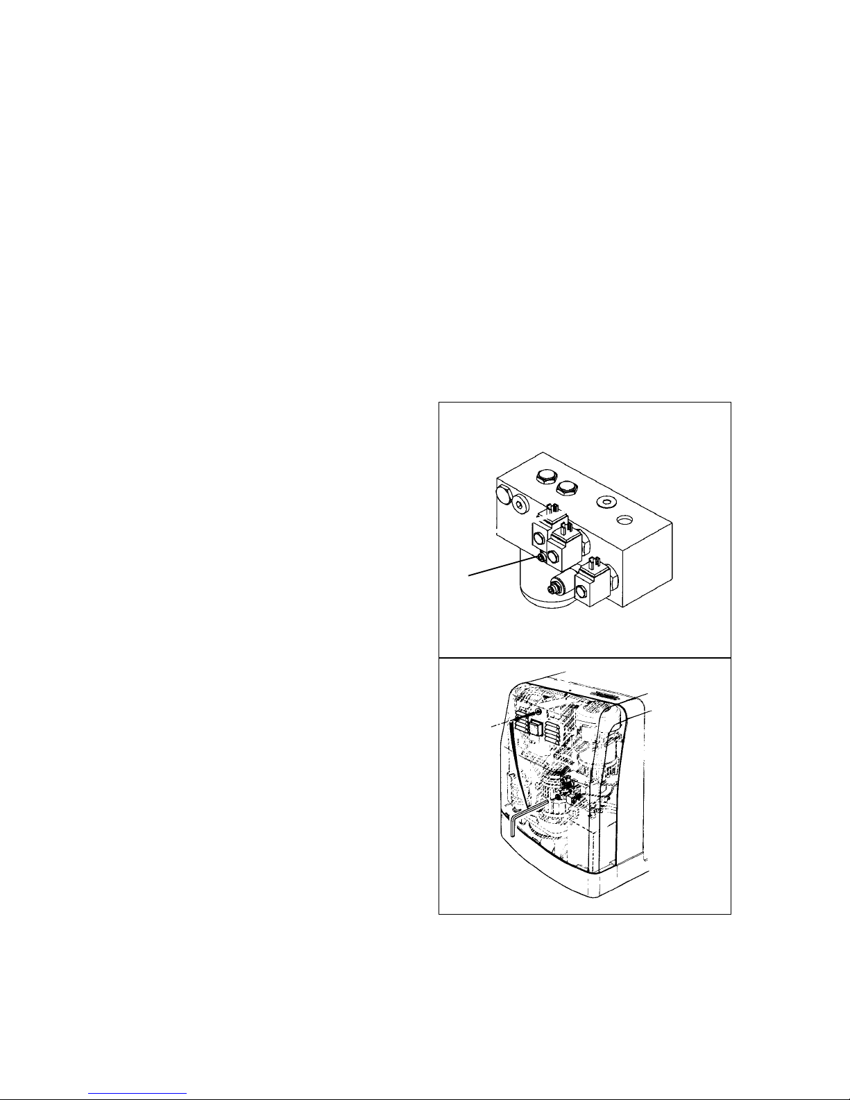
E 19
1298.GB
6.1 Emergency-STOP
When the automatic emergency stop facility has been activated (if, for example, the
guidance is lost, the electrical steering fails or the safety device is activated) the truck
is decelerated until standstill. Before putting it into operation again you must determine cause for the malfunction and eliminate the fault. Setting into operation has to be
performed according to these operating instruction of the manufacturer.
6.2 Emergency lowering of driver’s cabin
f
When using the emergency lowering facility make sure that all personnel stands clear
of the danger zone. The load lifting device is lowered by a person with the emergency
lowering facility located at the lower part. Driver and the helping person must communicate during this process. Both persons must stand in an area considered as safe,
so that they are not endangered by the actions.
The truck may only be put into operation again when the fault has been located and
eliminated.
If necessary, the cabin can be lowered by a second person at the ground.
– Slowly open drain valve (37) through
the bore hole with Allan key. Do not
unscrew screw completely.
– The cabin is lowered.
– Fasten Allan key to the truck again af-
ter opening the drain valve.
37
E 19
1298.GB
6.1 Emergency-STOP
When the automatic emergency stop facility has been activated (if, for example, the
guidance is lost, the electrical steering fails or the safety device is activated) the truck
is decelerated until standstill. Before putting it into operation again you must determi-
ne cause for the malfunction and eliminate the fault. Setting into operation has to be
performed according to these operating instruction of the manufacturer.
6.2 Emergency lowering of driver’s cabin
f
When using the emergency lowering facility make sure that all personnel stands clear
of the danger zone. The load lifting device is lowered by a person with the emergency
lowering facility located at the lower part. Driver and the helping person must commu-
nicate during this process. Both persons must stand in an area considered as safe,
so that they are not endangered by the actions.
The truck may only be put into operation again when the fault has been located and
eliminated.
If necessary, the cabin can be lowered by a second person at the ground.
– Slowly open drain valve (37) through
the bore hole with Allan key. Do not
unscrew screw completely.
– The cabin is lowered.
– Fasten Allan key to the truck again af-
ter opening the drain valve.
37
Page 47
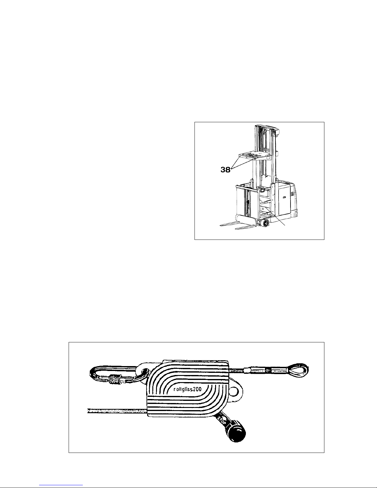
1298.GB
E 20
6.3 Leaving the driver’s cabin using the emergency rope-down facility
In addition to an emergency lowering device, load-handling trucks with a liftable operator seat having a reach of more than 3 m are equipped with a facility (emergency
rope-down facility) for the operator to reach the floor in the event the movement of the
elevated operator seat is blocked.
A
In the event the driver’s cabin is blocked and cannot be lowered manually, the operator must leave the cabin by means of the emergency rope-down facility.
The operator must be instructed in the handling of the emergency rope-down facility.
To leave the cabin using the emergency rope-down facility, proceed as follows:
– Turn the key switch to “0”.
– Push the main switch (Emergency-
STOP).
– Take out the emergency rope-down
device from the storage container
(39).
– Secure the rope-down device to the
eyelet (38) to the left or right of the
overhead guard.
– Uncoil and lower the rope without
loops; do not lead the rope over sharp
edges.
– Strap on emergency belt or harness.
– Secure belt to the rope-down device.
Roping down
f
Do not suspend yourself from the slack rope. Watch out for obstacles when roping
down!
– Pull rope tight.
– Leave cabin facing the truck.
– To lower yourself, push lever of the rope-down device upwards.
– To reduce the lowering speed, pull the braking lever downward.
– Please observe enclosed instructions.
39
secure to seat belt or
safety harness
secure to eyelet of
Driver's cabin
rope to ground level
push lever slowly up
to rope down
Slowly press
lever upwards
brake lever
downwards - STOP
1298.GB
E 20
6.3 Leaving the driver’s cabin using the emergency rope-down facility
In addition to an emergency lowering device, load-handling trucks with a liftable ope-
rator seat having a reach of more than 3 m are equipped with a facility (emergency
rope-down facility) for the operator to reach the floor in the event the movement of the
elevated operator seat is blocked.
A
In the event the driver’s cabin is blocked and cannot be lowered manually, the ope-
rator must leave the cabin by means of the emergency rope-down facility.
The operator must be instructed in the handling of the emergency rope-down facility.
To leave the cabin using the emergency rope-down facility, proceed as follows:
– Turn the key switch to “0”.
– Push the main switch (Emergency-
STOP).
– Take out the emergency rope-down
device from the storage container
(39).
– Secure the rope-down device to the
eyelet (38) to the left or right of the
overhead guard.
– Uncoil and lower the rope without
loops; do not lead the rope over sharp
edges.
– Strap on emergency belt or harness.
– Secure belt to the rope-down device.
Roping down
f
Do not suspend yourself from the slack rope. Watch out for obstacles when roping
down!
– Pull rope tight.
– Leave cabin facing the truck.
– To lower yourself, push lever of the rope-down device upwards.
– To reduce the lowering speed, pull the braking lever downward.
– Please observe enclosed instructions.
39
secure to seat belt or
safety harness
secure to eyelet of
Driver's cabin
rope to ground level
push lever slowly up
to rope down
Slowly press
lever upwards
brake lever
downwards - STOP
Page 48

E 21
1298.GB
6.4 Slack chain protection (acknowledge signal)
If the slack chain protection is activated, e.g. if the lift chain is slack or broken, all
functions are deactivated. After moving the adjusting levers to neutral position, the
cabin can be lifted by using (acknowledging) the operating switch (slack chain).
m
Before continuing with any operation the damage must be repaired.
All functions can be used again after the slack chain key went out.
6.5 Drive switch-off (o )
A difference is been made between drive switch-off with override or without override.
In case of drive switch-off with override, the "unlock driving" key must be pressed and
the driving lever must be operated as described under "Driving". In this way the truck
can be driven a crawling speed.
6.6 Lift switch-off (o)
If required by the local characteristics, the truck may be equipped for safety reasons
with automatic lift switch-off that is activated when reaching a certain lifting height.
A difference is been made between lift switch-off with override or without override.
f
If the lift switch-off is bypassed, the operator has to take special care to recognize any
obstacles when driving with the mast extended.
– The lift switch-off is bypassed by permanently pressing the pushbutton “Override
lift switch-off”.
– Inverted displaying of the lift switch-off on the display.
The pushbutton for drive switch-off and lift switch-off are located in the display.
Page 49

1298.GB
E 22
6.7 End of aisle safety device (o)
Vehicles with end of aisle safety device are decelerated before the aisle exit or in the
branch aisle. There are two basic versions:
1. Deceleration to standstill
2. Deceleration to 2.5 km/h
Other versions (affecting the subsequent travel speed, affecting the lifting height, etc.)
are available.
1. Deceleration to standstill:
When crossing the end of aisle safety magnet the vehicle is decelerated to standstill.
To continue the travel:
– Briefly release foot switch and press down again
The vehicle can be driven out of the narrow aisle at max. 2.5 km/h.
2. Deceleration to 2.5 km/h:
When crossing the end of aisle safety magnet the vehicle is decelerated to 2.5 km/h
and can be driven out of the narrow aisle at this speed.
m
In both cases the stopping distance depends on the travel speed.
f
The end of aisle safety deceleration is an optional function to support the operator
which, however, does not release the operator from his responsibility, for example, to
check the deceleration at the end of aisle and, if necessary, to initiate braking.
Page 50

E 23
1298.GB
6.8 IG Emergency operation
If the guiding antenna of the truck leaves the predetermined level area of the guiding
wire when operating the truck in induction guided operating mode, an emergency
stop is initiated immediately.
If the truck is travelling exactly in parallel along the guiding wire, no drive switch-off
will occur. However, the operator is warned by the indicator for „Tracking-in in
progress“ and the audible tracking signal being continuously on.
Automatic Emergency-STOP of the truck
If any of the monitoring functions for steering control, steering system, induction
guide, or safety circuits of the drive electronics or the power electronics of the truck
are activated, the truck will be stopped by the safety facilities to standstill.
To be able to resume driving after an Emergency-STOP, performing the following actions is required:
– Determine the possible cause for the Emergency-STOP.
– Press the Emergency-STOP button and release it again by turning it.
– If activated, switch off induction guide.
– Operate drive lever.
f
If the truck now starts to travel, check its proper function by manual steering and inductive forced steering.
Automatic and manual Emergency-STOP
If the truck cannot be restarted after eliminating the problem following automatic or
manual Emergency-STOP, the key-switch must be turned off and on again.
Subsequently, perform a reference drive in the following way:
Lift and lower the main lifter and the auxiliary lifter according to the symbol indicators
until the corresponding indicator extinguishes.
Perform reference drive
:
- REF- Reference drive: lift main lifter
-REF- Reference drive: lower main lifter
-REF- Reference drive: lift auxiliary lifter
-REF- Reference drive: lower auxiliary lifter
E 23
1298.GB
6.8 IG Emergency operation
If the guiding antenna of the truck leaves the predetermined level area of the guiding
wire when operating the truck in induction guided operating mode, an emergency
stop is initiated immediately.
If the truck is travelling exactly in parallel along the guiding wire, no drive switch-off
will occur. However, the operator is warned by the indicator for „Tracking-in in
progress“ and the audible tracking signal being continuously on.
Automatic Emergency-STOP of the truck
If any of the monitoring functions for steering control, steering system, induction
guide, or safety circuits of the drive electronics or the power electronics of the truck
are activated, the truck will be stopped by the safety facilities to standstill.
To be able to resume driving after an Emergency-STOP, performing the following ac-
tions is required:
– Determine the possible cause for the Emergency-STOP.
– Press the Emergency-STOP button and release it again by turning it.
– If activated, switch off induction guide.
– Operate drive lever.
f
If the truck now starts to travel, check its proper function by manual steering and in-
ductive forced steering.
Automatic and manual Emergency-STOP
If the truck cannot be restarted after eliminating the problem following automatic or
manual Emergency-STOP, the key-switch must be turned off and on again.
Subsequently, perform a reference drive in the following way:
Lift and lower the main lifter and the auxiliary lifter according to the symbol indicators
until the corresponding indicator extinguishes.
Perform reference drive
:
- REF- Reference drive: lift main lifter
-REF- Reference drive: lower main lifter
-REF- Reference drive: lift auxiliary lifter
-REF- Reference drive: lower auxiliary lifter
Page 51

1298.GB
E 24
6.9 Recovering the truck from a narrow aisle
To recover the truck from the narrow aisle, disengage brakes.
m
Deactivating the brakes may only be carried out by authorized and trained personnel!
If the brakes are deactivated, the truck must be parked at even floor level, since there
is no braking action.
– Fully lower the driver’s cabin.
A
Ask for the help of a second person. The second person must be trained and familiar
with the recovery procedure.
Loosen brake of the drive wheel
– Dismount the cover of the rear electro-
nics compartment.
– Screw in set screws (40) at the ma-
gnetic brake located above the drive
motor in order to loosen it.
Loosen brake of the drive wheel
Push tube (39) onto vent connection and
insert the other end of the tube into the
brake fluid reservoir located above.
f
Brake fluid is under pressure.
Danger of causticization!
– Open vent valve and allow emerging
brake fluid to drain into the brake fluid
reservoir.
– Close vent valve and brake fluid reser-
voir.
– The operatability of the brake system
is restored after restoring power and
after operating the foot switch several
times.
– Secure the tow rope to the rear weight
and carefully pull truck out of the nar-
row aisle.
m
Check braking deceleration value when
recommissioning the truck.
This work must only be carried out by
authorized service personnel.
40
Page 52

F 1
1298.GB
F Truck maintenance
1 Operational safety and protection of the environment
The checks and servicing operations contained in this chapter must be performed in
accordance with the intervals as indicated in the servicing checklists.
f
Modifications of truck assemblies, especially of the safety installations, are not permitted. On no account must the operational speeds of the truck be changed.
m
Only original spare parts have been passed by our quality assurance service. In order
to ensure safe and reliable operation only original spare parts of the manufacturer
must be used. Old parts and changed consumption type materials must be disposed
of in accordance with the applicable environmental protection regulations. The Oil
Change Service of the manufacturer is available for oil changes.
Upon completion of any checking and servicing activities, the operations contained in
section “Recommissioning” must be performed.
2 Safety regulations for repair
Servicing and maintenance personnel: Maintenance and repair of the floor
conveyors may only be performed by expert personnel of the manufacturer. The Service Organisation of the manufacturer has service engineers available that have been
specifically trained for these tasks. We therefore advise to conclude a maintenance
contract with the manufacturer’s Service Base responsible for the area.
Lifting and jacking up: When a fork-lift truck is to be lifted, the lifting gear must only
be secured to the points specially provided for this purpose. When the truck is to be
jacked up, suitable measures must be taken to prevent the truck from slipping or tipping over (use of chocks, wooden blocks). Work underneath raised forks must only
be carried out, when the fork is immobilised and supported by a chain of adequate
strength.
Cleaning operations: No inflammable liquids must be used when cleaning the industrial truck. Prior to performing cleaning operations all appropriate safety measures
must be taken to avoid sparking (e.g. due to short circuits). The battery connector
must be disconnected. Electric and electronic components must be cleaned with lowpressure air or suction air and a non-conducting, antistatic brush.
m
If the truck is to be cleaned using water or a steam jet, all electric and electronic assemblies have to be carefully covered beforehand, as humidity will cause malfunctions.
Steam-cleaning is not permitted.
Upon the completion of cleaning work the operations detailed in section “Recommissioning” have to be performed.
F 1
1298.GB
F Truck maintenance
1 Operational safety and protection of the environment
The checks and servicing operations contained in this chapter must be performed in
accordance with the intervals as indicated in the servicing checklists.
f
Modifications of truck assemblies, especially of the safety installations, are not per-
mitted. On no account must the operational speeds of the truck be changed.
m
Only original spare parts have been passed by our quality assurance service. In order
to ensure safe and reliable operation only original spare parts of the manufacturer
must be used. Old parts and changed consumption type materials must be disposed
of in accordance with the applicable environmental protection regulations. The Oil
Change Service of the manufacturer is available for oil changes.
Upon completion of any checking and servicing activities, the operations contained in
section “Recommissioning” must be performed.
2 Safety regulations for repair
Servicing and maintenance personnel: Maintenance and repair of the floor
conveyors may only be performed by expert personnel of the manufacturer. The Ser-
vice Organisation of the manufacturer has service engineers available that have been
specifically trained for these tasks. We therefore advise to conclude a maintenance
contract with the manufacturer’s Service Base responsible for the area.
Lifting and jacking up: When a fork-lift truck is to be lifted, the lifting gear must only
be secured to the points specially provided for this purpose. When the truck is to be
jacked up, suitable measures must be taken to prevent the truck from slipping or tip-
ping over (use of chocks, wooden blocks). Work underneath raised forks must only
be carried out, when the fork is immobilised and supported by a chain of adequate
strength.
Cleaning operations: No inflammable liquids must be used when cleaning the indu-
strial truck. Prior to performing cleaning operations all appropriate safety measures
must be taken to avoid sparking (e.g. due to short circuits). The battery connector
must be disconnected. Electric and electronic components must be cleaned with low-
pressure air or suction air and a non-conducting, antistatic brush.
m
If the truck is to be cleaned using water or a steam jet, all electric and electronic as-
semblies have to be carefully covered beforehand, as humidity will cause mal-
functions.
Steam-cleaning is not permitted.
Upon the completion of cleaning work the operations detailed in section “Recommis-
sioning” have to be performed.
Page 53

1298.GB
F 2
Working on the electrical installation: All work on the electrical installation must be
carried out only by electrotechnically skilled personnel. Before commencing any work
on the electric system, all measures required to prevent electric shocks have to be
taken. For battery-operated floor conveyors, the floor conveyor must also be depowered by removing the battery plug.
Welding operations: To prevent any damage to electric or electronic components,
these have to be removed from the fork-lift truck before any welding operations are
undertaken.
Settings: When repairing or replacing hydraulic, electric or electronic components or
assemblies, all truck-specific settings have to be retained.
Tire equipment: The quality of the tires greatly affects the stability and the driving
behaviour of the fork-lift truck. Modifications must only be carried out after discussion
with the manufacturer. When replacing wheels or tires, it must be ensured that the
truck remains level (tires and wheels must always be replaced in pairs, i.e. left and
right together).
Lift chains: The lift chains wear rapidly if not lubricated. The intervals stated in the
service checklist apply for use in normal environment. For applications in aggravated
conditions (dust, temperature), frequent re-lubrication must be performed. Use the
correct chain spray oil as prescribed. The mere exterior application of grease does
not provide sufficient lubrication.
Hydraulic hoses: The hoses must be replaced after a service life of six years. When
replacing hydraulic components the hoses in this hydraulic system should be replaced.
1298.GB
F 2
Working on the electrical installation: All work on the electrical installation must be
carried out only by electrotechnically skilled personnel. Before commencing any work
on the electric system, all measures required to prevent electric shocks have to be
taken. For battery-operated floor conveyors, the floor conveyor must also be depowe-
red by removing the battery plug.
Welding operations: To prevent any damage to electric or electronic components,
these have to be removed from the fork-lift truck before any welding operations are
undertaken.
Settings: When repairing or replacing hydraulic, electric or electronic components or
assemblies, all truck-specific settings have to be retained.
Tire equipment: The quality of the tires greatly affects the stability and the driving
behaviour of the fork-lift truck. Modifications must only be carried out after discussion
with the manufacturer. When replacing wheels or tires, it must be ensured that the
truck remains level (tires and wheels must always be replaced in pairs, i.e. left and
right together).
Lift chains: The lift chains wear rapidly if not lubricated. The intervals stated in the
service checklist apply for use in normal environment. For applications in aggravated
conditions (dust, temperature), frequent re-lubrication must be performed. Use the
correct chain spray oil as prescribed. The mere exterior application of grease does
not provide sufficient lubrication.
Hydraulic hoses: The hoses must be replaced after a service life of six years. When
replacing hydraulic components the hoses in this hydraulic system should be repla-
ced.
Page 54

F 3
1298.GB
3 Maintenance and service
Thorough and expert servicing is one of the most important preconditions for safe
operation of the fork-lift truck. The neglect of regular servicing intervals can lead to
fork-lift failure and constitutes a potential hazard to personnel and operation.
m
The indicated servicing intervals are based on single-shift operation under normal
operating conditions. For applications in dusty environments, or involving large temperature fluctuations or multiple-shift operation, the servicing intervals must be shortened accordingly.
The following servicing checklist indicates the operations to be performed and the respective intervals to be observed. The following maintenance intervals are defined:
W1 = Every 50 operating hours, but at least once per week
M3 = Every 500 operating hours, but at least every 3 months
M6 = Every 1000 operating hours, but at least every 6 months
M12 = Every 2000 operating hours, but at least every 12 months
In the running-in phase of the truck, the following additional operations have to be carried out:
After the first 100 operating hours:
– Check the wheel nuts for security and retighten, if required.
– Check the hydraulic connections for leaks and retighten, if required.
After the first 500 operating hours:
– Change the hydraulic oil and hydraulic oil filter.
F 3
1298.GB
3 Maintenance and service
Thorough and expert servicing is one of the most important preconditions for safe
operation of the fork-lift truck. The neglect of regular servicing intervals can lead to
fork-lift failure and constitutes a potential hazard to personnel and operation.
m
The indicated servicing intervals are based on single-shift operation under normal
operating conditions. For applications in dusty environments, or involving large tem-
perature fluctuations or multiple-shift operation, the servicing intervals must be shor-
tened accordingly.
The following servicing checklist indicates the operations to be performed and the re-
spective intervals to be observed. The following maintenance intervals are defined:
W1 = Every 50 operating hours, but at least once per week
M3 = Every 500 operating hours, but at least every 3 months
M6 = Every 1000 operating hours, but at least every 6 months
M12 = Every 2000 operating hours, but at least every 12 months
In the running-in phase of the truck, the following additional operations have to be car-
ried out:
After the first 100 operating hours:
– Check the wheel nuts for security and retighten, if required.
– Check the hydraulic connections for leaks and retighten, if required.
After the first 500 operating hours:
– Change the hydraulic oil and hydraulic oil filter.
Page 55

1298.GB
F 4
4 Maintenance checklist KMS 100
a) Wheel nuts to be first checked for tightness after approx. 100 operating hours; tighten, if
necessary.
b) Hydraulic connections to be first checked for leakage after approx. 100 operating hours;
tighten, if necessary.
d) First change after 500 operating hours
A
The maintenance intervals refer to normal service conditions.
In case of aggravated conditions, the intervals must be reduced as required.
Maintenance intervals
Standard = t WMMM
13612
Chassis/
superstructure:
1.1 Check all load bearing elements for damage t
1.2 Check all bolted connections t
1.3 Check Operator platform for correct functioning and damages
t
1.4 Check marking locations, identification labels and warning
signs for readability; replace if necessary
t
Drive unit: 2.1 Grease seating between drive motor and transmission t
2.2 Check the transmission for noises and leakage t
2.3 Check the transmission oil level t
2.4 Change the gear oil t
Wheels: 3.1 Check for wear and damage t
3.2 Check seating and fixing a) t
Steering: 4.1 Lubricate steering pinion and ring gear at the transmission t
4.2 Check the wheel position indicator for correct functioning
and alignment
t
4.3 Check the distance between guide rollers and rail guide on
the entire length of the rails. The play between the two guide rollers should be 0 to 5 mm (measured across the axle).
Rollers must not jam.
t
Brake
system:
5.1 Check for correct function and adjustment t
5.2 Check the brake linings for wear t
5.3 Check the brake linkage; adjust and grease, if necessary t
5.4 Check the brake lines, connections and brake fluid level t
5.5 Check the brake fluid t
5.6 Change the brake fluid t
1298.GB
F 4
4 Maintenance checklist KMS 100
a) Wheel nuts to be first checked for tightness after approx. 100 operating hours; tighten, if
necessary.
b) Hydraulic connections to be first checked for leakage after approx. 100 operating hours;
tighten, if necessary.
d) First change after 500 operating hours
A
The maintenance intervals refer to normal service conditions.
In case of aggravated conditions, the intervals must be reduced as required.
Maintenance intervals
Standard = t WMMM
13612
Chassis/
superstruc-
ture:
1.1 Check all load bearing elements for damage t
1.2 Check all bolted connections t
1.3 Check Operator platform for correct functioning and dama-
ges
t
1.4 Check marking locations, identification labels and warning
signs for readability; replace if necessary
t
Drive unit: 2.1 Grease seating between drive motor and transmission t
2.2 Check the transmission for noises and leakage t
2.3 Check the transmission oil level t
2.4 Change the gear oil t
Wheels: 3.1 Check for wear and damage t
3.2 Check seating and fixing a) t
Steering: 4.1 Lubricate steering pinion and ring gear at the transmission t
4.2 Check the wheel position indicator for correct functioning
and alignment
t
4.3 Check the distance between guide rollers and rail guide on
the entire length of the rails. The play between the two gui-
de rollers should be 0 to 5 mm (measured across the axle).
Rollers must not jam.
t
Brake
system:
5.1 Check for correct function and adjustment t
5.2 Check the brake linings for wear t
5.3 Check the brake linkage; adjust and grease, if necessary t
5.4 Check the brake lines, connections and brake fluid level t
5.5 Check the brake fluid t
5.6 Change the brake fluid t
Page 56

F 5
1298.GB
b) Hydraulic connections to be first checked for leakage after approx. 100 operating hours;
tighten, if necessary.
d) First change after 500 operating hours
p) Replace hydraulic hoses after 6 years of operation
Maintenance intervals
Standard = t WMMM
13612
Hydraulic
system:
6.1 Check function t
6.2 Check all connections for leakage and damage b) t
6.3 Check hydraulic cylinders for leakage, damage and secure
attachment
t
6.4 Check the oil level t
6.5 Check the hose line for correct functioning and damage t
6.6 Check breather and vent filters at the hydraulic reservoir t
6.7 Change breather and vent filters at the hydraulic reservoir t
6.8 Change hydraulic oil and filter insert d) t
6.9 Check the pressure relief valves for correct functioning t
6.10 Check hydraulic lines for tightness and damage p) t
Electrical
system.
7.1 Check the discharge of static electricity t
7.2 Check function t
7.3 Check all cables for secure connection and damage t
7.4 Check the cable runs for correct functioning and damage t
7.5 Check the warning facilities and safety switches for correct
functioning
t
7.6 Check all sensors for secure attachment, damage, cleanliness and correct functioning
t
7.7 Check the instrument and indicators for correct functioning t
7.8 Check contactors and relays, replace wearing parts, if necessary
t
7.9 Check the fuses for correct amperage t
Electric
motors:
8.2 Check the motor for secure attachment t
Battery: 9.1 Check acid density, acid level and cell voltage t
9.2 Check the terminals for secure attachment and apply pole
grease
t
9.3 Clean battery connections, check for tight fit t
9.4 Check the battery cables for damage and replace, if necessary
t
F 5
1298.GB
b) Hydraulic connections to be first checked for leakage after approx. 100 operating hours;
tighten, if necessary.
d) First change after 500 operating hours
p) Replace hydraulic hoses after 6 years of operation
Maintenance intervals
Standard = t WMMM
13612
Hydraulic
system:
6.1 Check function t
6.2 Check all connections for leakage and damage b) t
6.3 Check hydraulic cylinders for leakage, damage and secure
attachment
t
6.4 Check the oil level t
6.5 Check the hose line for correct functioning and damage t
6.6 Check breather and vent filters at the hydraulic reservoir t
6.7 Change breather and vent filters at the hydraulic reservoir t
6.8 Change hydraulic oil and filter insert d) t
6.9 Check the pressure relief valves for correct functioning t
6.10 Check hydraulic lines for tightness and damage p) t
Electrical
system.
7.1 Check the discharge of static electricity t
7.2 Check function t
7.3 Check all cables for secure connection and damage t
7.4 Check the cable runs for correct functioning and damage t
7.5 Check the warning facilities and safety switches for correct
functioning
t
7.6 Check all sensors for secure attachment, damage, cleanli-
ness and correct functioning
t
7.7 Check the instrument and indicators for correct functioning t
7.8 Check contactors and relays, replace wearing parts, if ne-
cessary
t
7.9 Check the fuses for correct amperage t
Electric
motors:
8.2 Check the motor for secure attachment t
Battery: 9.1 Check acid density, acid level and cell voltage t
9.2 Check the terminals for secure attachment and apply pole
grease
t
9.3 Clean battery connections, check for tight fit t
9.4 Check the battery cables for damage and replace, if neces-
sary
t
Page 57

1298.GB
F 6
j) Chain to be first checked after approx. 100 operating hours; tighten, if necessary.
e) IG: induction-guided trucks
Maintenance intervals
Standard = t WMMM
13612
Lifting device 10.1 Apply grease to rollers and side run areas of idler pulleys
in the hoist frame profiles.
t
10.2 Check secure attachment of hoist frame t
10.3 Check hoisting chains and chain guide for wear; adjust
and grease j)
t
10.4 Visual check of rollers, slide pieces and stops t
10.5 Check hoisting frame seatings t
10.7 Check fork tines and fork carrier for wear and damage t
10.8 Lubricate lubricating points of the chain rollers t
Attachments: 11.1 Check function t
11.2 Check secure attachment at the device and supporting
elements
t
11.3 Check seatings, guides and stops for wear and damage;
apply grease
t
Lubrication
service:
12.1 Grease truck according to lubrication plan t
General measurements:
13.1 Check electrical system for short to ground t
13.2 Check driving speed and braking distance t
13.3 Check lifting and lowering speed t
13.4 Check safety faciliti es and switch-off devices t
13.5 IG: Check amperage of guide wire; re-adjust,
if necessary e)
t
13.6 Check driving behavior on IG wire and maximum deviation; re-adjust, if necessary e)
t
13.7 Check track-in and driving behaviour on the IG wire
during aisle track-in e)
t
13.8 Check IG emergency STOP function e) t
Demonstration:
14.1 Perform a trial run under a nominal load t
14.2 Upon completion of servicing operations, demonstrate
the truck to the person responsible
t
1298.GB
F 6
j) Chain to be first checked after approx. 100 operating hours; tighten, if necessary.
e) IG: induction-guided trucks
Maintenance intervals
Standard = t WMMM
13612
Lifting device 10.1 Apply grease to rollers and side run areas of idler pulleys
in the hoist frame profiles.
t
10.2 Check secure attachment of hoist frame t
10.3 Check hoisting chains and chain guide for wear; adjust
and grease j)
t
10.4 Visual check of rollers, slide pieces and stops t
10.5 Check hoisting frame seatings t
10.7 Check fork tines and fork carrier for wear and damage t
10.8 Lubricate lubricating points of the chain rollers t
Attachments: 11.1 Check function t
11.2 Check secure attachment at the device and supporting
elements
t
11.3 Check seatings, guides and stops for wear and damage;
apply grease
t
Lubrication
service:
12.1 Grease truck according to lubrication plan t
General mea-
surements:
13.1 Check electrical system for short to ground t
13.2 Check driving speed and braking distance t
13.3 Check lifting and lowering speed t
13.4 Check safety faciliti es and switch-off devices t
13.5 IG: Check amperage of guide wire; re-adjust,
if necessary e)
t
13.6 Check driving behavior on IG wire and maximum devia-
tion; re-adjust, if necessary e)
t
13.7 Check track-in and driving behaviour on the IG wire
during aisle track-in e)
t
13.8 Check IG emergency STOP function e) t
Demonstrati-
on:
14.1 Perform a trial run under a nominal load t
14.2 Upon completion of servicing operations, demonstrate
the truck to the person responsible
t
Page 58

F 7
1298.GB
s slide faces g grease nipples
D
E
g
s
G
G
E
gs
E
g
A
B
E
s
D
F 7
1298.GB
s slide faces g grease nipples
D
E
g
s
G
G
E
gs
E
g
A
B
E
s
D
Page 59

1298.GB
F 8
4.1 Operating material
Handling operating material: Consumption type material must always be handled
properly. Manufacturer's instructions to be observed.
f
Improper handling endangers health, life and environment. Operating material must
only be stored in containers conforming to specification. They might be inflammable
and must not come into contact with hot components or open fire.
When filling in consumption type materials, use clean containers only. It is prohibited
to mix consumption type materials of different grades or qualities, except if mixing is
expressively prescribed in these operating instructions. -This instruction may only be
ignored, if another mixing ratio is explicitly prescribed in this manual.
Avoid any spilling. Spilled liquid must be removed immediately using a suitable binding agent, and the mixture of consumption type material and binding agent is to be
disposed of according to the regulations.
* In addition 2% additive 68/D from Dea Fuchs
Qty Description Used for:
*A 33 l Hydraulic oil
H-LPD22
Hydraulic system
B 2.5 l SAE 80 EP API GL 4 Transmission
D 0.18 l SAE J 1703
FMVSS 116
DOT 3 and DOT 4
Hydraulic
braking system
E Multi-purpose Lithium
grease KP 2 (N)
DIN 51502
General
F Multi-purpose Lithium
grease
KPF L2 N (M) with MOS
2
DIN 502
Toothed racks
G Chain spray Hoisting chains
H High-temperature grease Front wheel bearings
1298.GB
F 8
4.1 Operating material
Handling operating material: Consumption type material must always be handled
properly. Manufacturer's instructions to be observed.
f
Improper handling endangers health, life and environment. Operating material must
only be stored in containers conforming to specification. They might be inflammable
and must not come into contact with hot components or open fire.
When filling in consumption type materials, use clean containers only. It is prohibited
to mix consumption type materials of different grades or qualities, except if mixing is
expressively prescribed in these operating instructions. -This instruction may only be
ignored, if another mixing ratio is explicitly prescribed in this manual.
Avoid any spilling. Spilled liquid must be removed immediately using a suitable bin-
ding agent, and the mixture of consumption type material and binding agent is to be
disposed of according to the regulations.
* In addition 2% additive 68/D from Dea Fuchs
Qty Description Used for:
*A 33 l Hydraulic oil
H-LPD22
Hydraulic system
B 2.5 l SAE 80 EP API GL 4 Transmission
D 0.18 l SAE J 1703
FMVSS 116
DOT 3 and DOT 4
Hydraulic
braking system
E Multi-purpose Lithium
grease KP 2 (N)
DIN 51502
General
F Multi-purpose Lithium
grease
KPF L2 N (M) with MOS
2
DIN 502
Toothed racks
G Chain spray Hoisting chains
H High-temperature grease Front wheel bearings
Page 60
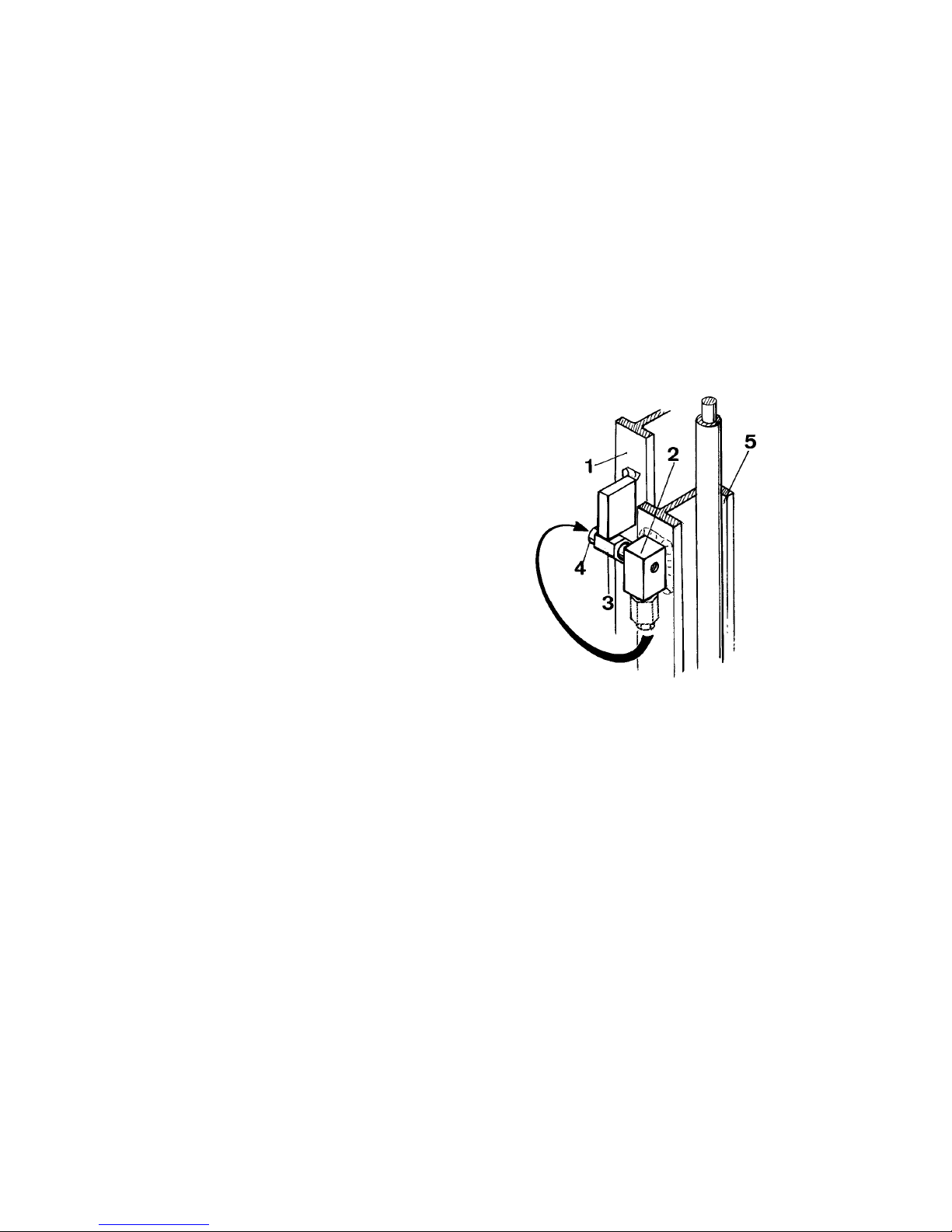
F 9
1298.GB
5 Description of servicing operations
5.2 Prepare the truck for the performance of servicing and maintenance operations
All required safety measures must be taken to prevent any accidents in the course of
the servicing and maintenance operations. The following preparatory operations
must be performed:
– Park the truck and render it safe (refer to chapter E).
– Disconnect the battery plug to prevent accidental starting of the truck.
– When work has to be performed under the jacked-up truck, suitable measures must
be taken to prevent any dropping, tilting or slipping of the truck.
f
When lifting the truck, the instructions contained in chapter “Transportation and Commissioning” have to be observed (refer to chapter C).
5.3 Securing the driver platform
The driver platform can be secured in
elevated position.
– Lift the driver platform until the inner
mast (1) is positioned above the carrier of the load lifting safety device.
– Screw out the fastening screw (4) and
dismount the safety bolt (3) from the
carrier (2) at the hoisting frame (5).
– Position the safety bolt to the vertical
hole of the carrier and screw on.
– Lower the driver platform very slowly
until the inner mast rests on the safety
bolt.
5.4 Cleaning the hoisting chains
m
It is very important to keep all hoisting
chains and swivels are kept clean and
well greased. Hoisting chains are safety
elements.
The chains must not show any considerable dirt accumulations. Cleaning is
only allowed with paraffin derivatives,
e.g. kerosene or Diesel oils.
Never clean chains with high-pressure
steam cleaners, cold cleaners, or chemical cleaning solutions.
F 9
1298.GB
5 Description of servicing operations
5.2 Prepare the truck for the performance of servicing and maintenance operations
All required safety measures must be taken to prevent any accidents in the course of
the servicing and maintenance operations. The following preparatory operations
must be performed:
– Park the truck and render it safe (refer to chapter E).
– Disconnect the battery plug to prevent accidental starting of the truck.
– When work has to be performed under the jacked-up truck, suitable measures must
be taken to prevent any dropping, tilting or slipping of the truck.
f
When lifting the truck, the instructions contained in chapter “Transportation and Com-
missioning” have to be observed (refer to chapter C).
5.3 Securing the driver platform
The driver platform can be secured in
elevated position.
– Lift the driver platform until the inner
mast (1) is positioned above the carri-
er of the load lifting safety device.
– Screw out the fastening screw (4) and
dismount the safety bolt (3) from the
carrier (2) at the hoisting frame (5).
– Position the safety bolt to the vertical
hole of the carrier and screw on.
– Lower the driver platform very slowly
until the inner mast rests on the safety
bolt.
5.4 Cleaning the hoisting chains
m
It is very important to keep all hoisting
chains and swivels are kept clean and
well greased. Hoisting chains are safety
elements.
The chains must not show any consi-
derable dirt accumulations. Cleaning is
only allowed with paraffin derivatives,
e.g. kerosene or Diesel oils.
Never clean chains with high-pressure
steam cleaners, cold cleaners, or chemi-
cal cleaning solutions.
Page 61
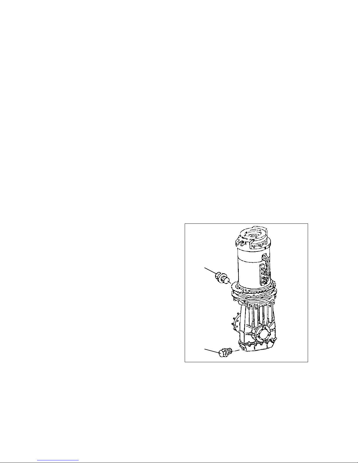
1298.GB
F 10
5.5 Inspecting the hoisting chains
Excessive wear and exterior damages:
According to the official regulations a chain is to be considered as worn-off, when it
has stretched by 3% in the section around the guide pulley. For safety reasons, the
manufacturer recommends to replace the chain when it has stretched by 2%.
If exterior damages are noticeable the chain is to be replaced immediately, since these damages will lead to fatigue fractures.
m
If the truck is equipped with two sets of hoisting chains, the chains must always be
replaced in pairs. Only this guarantees a balanced load distribution to both chains.
When replacing the chain, the link pins between chain latch and the chain itself must
also be replaced. Only original replacement parts of the manufacturer may be used.
5.6 Repairing the chain
Only original replacement parts of the manufacturer may be used when repairing a
chain. The rivet heads must be ground-off before dismounting. This prevents the pin
from damaging the borehole when being forced through the intermediate ring respectively the inner link. Dismounted pins and rings may not be re-used.
5.7 Changing the transmission oil
m
Under no circumstances oil may be allowed to enter the ground or the sewer system.
Waste oil must be securely stored until it is disposed of properly.
Draining the oil:
– Place an oil pan under the transmissi-
on.
– Open the oil drain plug (7) at the trans-
mission bottom and drain the oil.
Refilling oil:
– Screw in oil drain plug (7) and tighten.
– Open the oil level and filling plug (6) at
the transmission top.
– Fill with new transmission oil up to the
oil level plug opening.
– Screw in the oil level and filling plug
(6).
A
Since the waste oils must be disposed of
in accordance with the applicable environmental protection regulations and because special tools and skills may be required for changing transmission oil, hydraulic
oil, and brake fluid as well for replacing filters, these operations should be performed
by the manufacturer’s service personnel.
6
7
1298.GB
F 10
5.5 Inspecting the hoisting chains
Excessive wear and exterior damages:
According to the official regulations a chain is to be considered as worn-off, when it
has stretched by 3% in the section around the guide pulley. For safety reasons, the
manufacturer recommends to replace the chain when it has stretched by 2%.
If exterior damages are noticeable the chain is to be replaced immediately, since the-
se damages will lead to fatigue fractures.
m
If the truck is equipped with two sets of hoisting chains, the chains must always be
replaced in pairs. Only this guarantees a balanced load distribution to both chains.
When replacing the chain, the link pins between chain latch and the chain itself must
also be replaced. Only original replacement parts of the manufacturer may be used.
5.6 Repairing the chain
Only original replacement parts of the manufacturer may be used when repairing a
chain. The rivet heads must be ground-off before dismounting. This prevents the pin
from damaging the borehole when being forced through the intermediate ring respec-
tively the inner link. Dismounted pins and rings may not be re-used.
5.7 Changing the transmission oil
m
Under no circumstances oil may be allowed to enter the ground or the sewer system.
Waste oil must be securely stored until it is disposed of properly.
Draining the oil:
– Place an oil pan under the transmissi-
on.
– Open the oil drain plug (7) at the trans-
mission bottom and drain the oil.
Refilling oil:
– Screw in oil drain plug (7) and tighten.
– Open the oil level and filling plug (6) at
the transmission top.
– Fill with new transmission oil up to the
oil level plug opening.
– Screw in the oil level and filling plug
(6).
A
Since the waste oils must be disposed of
in accordance with the applicable envi-
ronmental protection regulations and be-
cause special tools and skills may be required for changing transmission oil, hydraulic
oil, and brake fluid as well for replacing filters, these operations should be performed
by the manufacturer’s service personnel.
6
7
Page 62

F 11
1298.GB
5.8 Cleaning the vent filter
Screw out the vent filter together with the
oil dip stick (8) and clean with compressed air or cleaning solution.
m
Used filters must be disposed of properly.
5.9 Changing of hydraulic oil filter
– Screw off the hydraulic oil filler cap (9).
– Change the filter insert; if the O-ring is
damaged, it must be replaced, too.
Slightly oil the O-ring before insertion.
– Remount the filler cap.
F 11
1298.GB
5.8 Cleaning the vent filter
Screw out the vent filter together with the
oil dip stick (8) and clean with compres-
sed air or cleaning solution.
m
Used filters must be disposed of proper-
ly.
5.9 Changing of hydraulic oil filter
– Screw off the hydraulic oil filler cap (9).
– Change the filter insert; if the O-ring is
damaged, it must be replaced, too.
Slightly oil the O-ring before insertion.
– Remount the filler cap.
Page 63
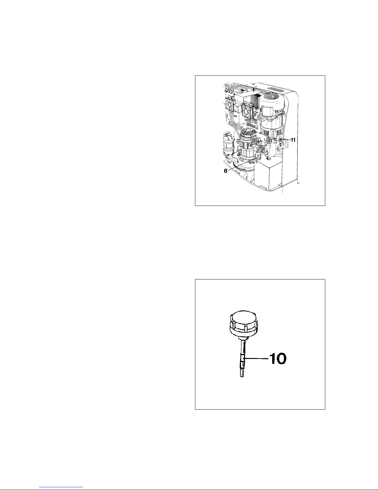
1298.GB
F 12
5.10 Hydraulic oil
– Prepare the truck for the performance of servicing and maintenance operations.
m
Under no circumstances oil may be allowed to enter the ground or the sewer system.
Waste oil must be securely stored until it is disposed of properly.
Draining the oil:
Take out the vent filter (8) and remove oil
by suction. If this is not possible, the oil
can be drained at the bottom of the hydraulic reservoir after unscrewing the oil
drain plug.
Refilling oil:
Remount the oil drain plug. Fill with hydraulic oil to the upper level mark (max.)
at the oil dip stick (10). Remount the vent
filter.
Check hydraulic oil level:
With the hoisting frame fully lowered,
check whether the hydraulic oil level is between minimum and maximum mark of the
oil dip stick (10).
If not, refill new hydraulic oil up to the correct level.
5.11 Hydraulic hoses
The hydraulic hose lines must be replaced after a service life of 6 years, see “Safety
Regulation for Hydraulic Hose Lines ZH 1/74”.
5.12 Checking the brake fluid
f
Brake fluid is poisonous and must only
be stored in closed original containers.
Furthermore, be aware that brake fluid is
aggressive to the trucks painted surfaces.
The brake fluid is filled in the factory and
must be changed at least after two
years, since the brake fluid changes in
the course of time and loses its original
characteristics.
The brake fluid reservoir (11) is located
in the rear of the truck and can be accessed after removing the cover. The brake
fluid reservoir should always be filled up
to 2 cm below the reservoir’s closing cap.
The stipulated brake fluid must be used.
The braking system must always be sealed tightly.
1298.GB
F 12
5.10 Hydraulic oil
– Prepare the truck for the performance of servicing and maintenance operations.
m
Under no circumstances oil may be allowed to enter the ground or the sewer system.
Waste oil must be securely stored until it is disposed of properly.
Draining the oil:
Take out the vent filter (8) and remove oil
by suction. If this is not possible, the oil
can be drained at the bottom of the hy-
draulic reservoir after unscrewing the oil
drain plug.
Refilling oil:
Remount the oil drain plug. Fill with hy-
draulic oil to the upper level mark (max.)
at the oil dip stick (10). Remount the vent
filter.
Check hydraulic oil level:
With the hoisting frame fully lowered,
check whether the hydraulic oil level is between minimum and maximum mark of the
oil dip stick (10).
If not, refill new hydraulic oil up to the correct level.
5.11 Hydraulic hoses
The hydraulic hose lines must be replaced after a service life of 6 years, see “Safety
Regulation for Hydraulic Hose Lines ZH 1/74”.
5.12 Checking the brake fluid
f
Brake fluid is poisonous and must only
be stored in closed original containers.
Furthermore, be aware that brake fluid is
aggressive to the trucks painted sur-
faces.
The brake fluid is filled in the factory and
must be changed at least after two
years, since the brake fluid changes in
the course of time and loses its original
characteristics.
The brake fluid reservoir (11) is located
in the rear of the truck and can be acces-
sed after removing the cover. The brake
fluid reservoir should always be filled up
to 2 cm below the reservoir’s closing cap.
The stipulated brake fluid must be used.
The braking system must always be sealed tightly.
Page 64

F 13
1298.GB
5.13 Checking the electric fuses
– Prepare the truck for the performance of servicing and maintenance operations (re-
fer to chapter F).
– Referring to the table, check all fuses for correct rating and replace, where required.
Item Description Protection of: Value
12 2F15 Hydraulic system 250 A
13 1F11 Driving 160 A
14 3F10 Steering system 30 A
15 F3.1 Control current 24 V / 10 A
16 F1.2 Converter U16 input 48 V / 3.15 A
17 5F2 Converter U16 output 6,3 A
18 F2.1 Control current 48 V / 10 V
19 1F3 Drive control 3.15 A
20 2F10 Hydraulic control 3.15 A
Page 65

1298.GB
F 14
5.14 Recommissioning the truck
Recommissioning of the truck following the performance of cleaning or maintenance
work is permitted only after the following operations have been performed:
– Check the horn for proper functioning.
– Check the main switch (Emergency-STOP) for correct function.
– Check the brake for correct function.
6 Taking the floor conveyor out of service
If the truck is to be decommissioned for more than two months, it must be parked in
a frost-free and dry location and all measures to be taken before, during and following
decommissioning must be performed as detailed below.
m
During decommissioning the truck must be jacked up ensuring that the wheels are
clear of the ground. Only this measure will ensure that wheels and wheel bearings do
not suffer damage.
If the truck is to be decommissioned for periods in excess of six months, the service
of the manufacturer must be contacted for further measures to be taken.
6.15 Operations to be performed prior to decommissioning
– Thoroughly clean the truck.
– Check the brakes.
– Check the hydraulic oil level and refill, if required (se chapter F).
– Apply a thin film of oil or grease to all parts not protected by a paint coating.
– Grease the truck as detailed in the lubrication chart (refer to chapter F).
– Recharge the battery (see chapter D).
– Disconnect and clean the battery. Apply pole grease to the battery terminals.
A
In addition to this, all instructions as given by the battery supplier have to be observed.
– Spray all exposed electrical contacts with a suitable contact spray.
6.16 Measures to be taken during decommissioning
Every 2 months:
– Recharge the battery (see chapter D).
m
For battery-driven trucks:
Regular recharging of the battery is very important. Otherwise, excessive depletion
of the battery would occur caused by self-discharging, which will result in the destruction of the battery caused by sulfatisation.
1298.GB
F 14
5.14 Recommissioning the truck
Recommissioning of the truck following the performance of cleaning or maintenance
work is permitted only after the following operations have been performed:
– Check the horn for proper functioning.
– Check the main switch (Emergency-STOP) for correct function.
– Check the brake for correct function.
6 Taking the floor conveyor out of service
If the truck is to be decommissioned for more than two months, it must be parked in
a frost-free and dry location and all measures to be taken before, during and following
decommissioning must be performed as detailed below.
m
During decommissioning the truck must be jacked up ensuring that the wheels are
clear of the ground. Only this measure will ensure that wheels and wheel bearings do
not suffer damage.
If the truck is to be decommissioned for periods in excess of six months, the service
of the manufacturer must be contacted for further measures to be taken.
6.15 Operations to be performed prior to decommissioning
– Thoroughly clean the truck.
– Check the brakes.
– Check the hydraulic oil level and refill, if required (se chapter F).
– Apply a thin film of oil or grease to all parts not protected by a paint coating.
– Grease the truck as detailed in the lubrication chart (refer to chapter F).
– Recharge the battery (see chapter D).
– Disconnect and clean the battery. Apply pole grease to the battery terminals.
A
In addition to this, all instructions as given by the battery supplier have to be obser-
ved.
– Spray all exposed electrical contacts with a suitable contact spray.
6.16 Measures to be taken during decommissioning
Every 2 months:
– Recharge the battery (see chapter D).
m
For battery-driven trucks:
Regular recharging of the battery is very important. Otherwise, excessive depletion
of the battery would occur caused by self-discharging, which will result in the destruc-
tion of the battery caused by sulfatisation.
Page 66

F 15
1298.GB
6.17 Recommissioning the truck
– Thoroughly clean the truck.
– Grease the truck as detailed in the lubrication chart (refer to chapter F).
– Clean the battery. Grease the terminal screws using pole grease and reconnect the
battery.
– Recharge the battery (see chapter D).
– Check if the transmission oil contains condensed water and change, if required.
– Check if the hydraulic oil contains condensed water and change, if required.
– Start up the truck (refer to chapter E).
A
For battery-driven trucks:
If switching troubles are experienced in the electric system, spray the exposed contacts with contact spray and remove a possible oxide layer on the contacts of the operating controls by repeated operation.
f
Upon recommissioning of the truck perform several brake tests immediately.
7 Safety checks to be performed at regular intervals and following any untoward
incidents
(D: UVV according to UVB 36)
At least once yearly, or after any untoward incident, the truck has to be checked by a
qualified inspector. The inspector must assess the condition of the truck from a standpoint purely concerned with safety aspects, uninfluenced by any company or economic circumstances. The inspector must be adequately informed and experienced to
be able to assess the condition of the truck and the effectiveness of the safety installations based on the technical rules and principles governing the inspection of trucks.
The inspection must comprise a comprehensive check of the technical condition of
the truck with regard to accident prevention aspects. Apart from this, the truck must
be thoroughly inspected for damage possibly caused by incorrect use of the truck.
The inspection results must be recorded in an inspection report. The report must be
kept available for a period spanning at least the next two inspection intervals.
The user has to ensure that all defects are eliminated without delay.
A
The manufacturer has set up a special safety service with specially qualified staff. As
visual proof that the truck has passed the safety inspection, a plaque will be affixed
to it. This plaque indicates in which month of which year the next test will be due.
F 15
1298.GB
6.17 Recommissioning the truck
– Thoroughly clean the truck.
– Grease the truck as detailed in the lubrication chart (refer to chapter F).
– Clean the battery. Grease the terminal screws using pole grease and reconnect the
battery.
– Recharge the battery (see chapter D).
– Check if the transmission oil contains condensed water and change, if required.
– Check if the hydraulic oil contains condensed water and change, if required.
– Start up the truck (refer to chapter E).
A
For battery-driven trucks:
If switching troubles are experienced in the electric system, spray the exposed con-
tacts with contact spray and remove a possible oxide layer on the contacts of the ope-
rating controls by repeated operation.
f
Upon recommissioning of the truck perform several brake tests immediately.
7 Safety checks to be performed at regular intervals and following any untoward
incidents
(D: UVV according to UVB 36)
At least once yearly, or after any untoward incident, the truck has to be checked by a
qualified inspector. The inspector must assess the condition of the truck from a stand-
point purely concerned with safety aspects, uninfluenced by any company or econo-
mic circumstances. The inspector must be adequately informed and experienced to
be able to assess the condition of the truck and the effectiveness of the safety instal-
lations based on the technical rules and principles governing the inspection of trucks.
The inspection must comprise a comprehensive check of the technical condition of
the truck with regard to accident prevention aspects. Apart from this, the truck must
be thoroughly inspected for damage possibly caused by incorrect use of the truck.
The inspection results must be recorded in an inspection report. The report must be
kept available for a period spanning at least the next two inspection intervals.
The user has to ensure that all defects are eliminated without delay.
A
The manufacturer has set up a special safety service with specially qualified staff. As
visual proof that the truck has passed the safety inspection, a plaque will be affixed
to it. This plaque indicates in which month of which year the next test will be due.
Page 67

1298.GB
F 16
1298.GB
F 16
 Loading...