

Page 1

Operating instructions
50274119
HC 10
G
05.02-
07.08
Page 2

0108.GB
Foreword
The present ORIGINAL OPERATING INSTRUCTIONS are designed to provide
sufficient instruction for the safe operation of the industrial truck. The information is
provided clearly and concisely. The chapters are arranged by letter. Each chapter
starts with page 1. The page identification consists of a chapter letter and a page
number.
For example: Page B 2 is the second page in chapter B.
The operating instructions detail different truck models. When operating and servicing
the truck, make sure that the instructions apply to your truck model.
Safety instructions and important explanations are indicated by the following
graphics:
f
Used before safety instructions which must be observed to avoid danger to
personnel.
m
Used before notices which must be observed to avoid material damage.
A
Used before notices and explanations.
t Used to indicate standard equipment.
o Used to indicate optional equipment.
Our trucks are subject to ongoing development. Jungheinrich reserves the right to
alter the design, equipment and technical features of the truck. No guarantee of
particular features of the truck should therefore be inferred from the present operating
instructions.
Copyright
Copyright of these operating instructions remains with JUNGHEINRICH AG.
Jungheinrich Aktiengesellschaft
Am Stadtrand 35
22047 Hamburg - GERMANY
Telephone: +49 (0) 40/6948-0
www.jungheinrich.com
Page 3

0108.GB
0108.GB
Page 4

I 1
0708.GB
Table of contents
A Correct use and application of the truck
B Description of the truck
1 Application ........................................................................................... B 1
2 Description of the assemblies and functions ....................................... B 2
2.1 Truck ................................................................................................... B 3
3 Technical data - standard version ....................................................... B 4
3.1 Performance data for standard trucks ................................................. B 4
3.2 Dimensions ......................................................................................... B 4
3.3 Batteries and motor output .................................................................. B 4
3.4 EN standards ...................................................................................... B 6
3.5 Conditions for application .................................................................... B 6
4 Labels .................................................................................................. B 7
4.1 Truck identification plate ..................................................................... B 8
4.2 Load Diagram ...................................................................................... B 8
C Transportation and commissioning
1 Transportation by crane ...................................................................... C 1
2 Commissioning .................................................................................... C 1
D Battery - Servicing, recharging, replacement
1 Safety regulations governing the handling of lead-acid batteries ........ D 1
2 Battery types ....................................................................................... D 1
3 Charging the battery using the integrated charger .............................. D 2
4 Replacing the batteries ........................................................................ D 3
5 Battery Monitor .................................................................................... D 4
E Operation
1 Safety regulations governing the operation of the fork-lift truck .......... E 1
2 Description of the operating controls and indicators ........................... E 2
3 Starting up the truck ............................................................................ E 3
4 Operation of the fork-lift truck .............................................................. E 4
4.1 Safety regulations applicable when operating the truck ...................... E 4
4.2 Driving, steering, braking .................................................................... E 5
4.3 Picking up and setting down loads ...................................................... E 6
4.4 Parking the truck and rendering it safe ............................................... E 6
Page 5

0708.GB
I 2
F Maintenance of the fork-lift truck
1 Operational safety and environmental protection .................................F 1
2 Safety regulations applicable to truck maintenance .............................F 1
3 Maintenance and Inspection ................................................................F 3
4 Maintenance checklist HC ...................................................................F 4
5 HC Lubrication Schedule ......................................................................F 5
5.1 Fuels, coolants and lubricants ..............................................................F 6
6 Notes regarding maintenance ..............................................................F 6
6.1 Preparing the truck for maintenance work ...........................................F 6
6.2 Checking the electric fuses ..................................................................F 7
6.3 Recommissioning the truck ..................................................................F 7
7 Decommissioning the fork-lift truck ......................................................F 8
7.1 Measures to be taken during decommissioning ...................................F 8
7.2 Recommissioning the truck .................................................................F 8
8 Safety checks to be performed at regular intervals and following
any unusual incidents............................................................................F 9
9 Final de-commissioning, disposal ........................................................F 9
10 Faul localisation and identification .......................................................F 10
10.1 Fault localisation ..................................................................................F 10
Page 6

A 6
0502.GB
A Correct use and application of the truck
A
The “Guidelines for the Correct Use and Application of Industrial Trucks” (VDMA) are
included in the scope of delivery for this truck. The guidelines are part of these operating instructions and must always be heeded. National regulations are fully applicable.
The fork-lift truck described in these operating instructions is a truck that is suitable
for lifting and transporting loads.
It must be used, operated and maintained according to the information in these operating instructions. Any other uses are outside the design envelope and can lead to
injury to persons or damage to equipment and property. Above all, overloading
caused by excessively heavy or unbalanced loads must be avoided. The max. admissible load to be picked up is indicated on the identification plate or load diagram label
shown on the truck. The fork-lift truck must not be operated in spaces subject to fire
or explosion hazards, or in spaces where corrosive or very dusty atmospheres prevail.
Duties of the user: A “user” within the meaning of these operating instructions is defined as any natural or legal person who either uses the fork-lift truck himself, or on
whose behalf it is used. In special cases (e.g. leasing or renting), the user is considered the person, who, in accordance with existing contractual agreements between the
owner and the user of the fork-lift truck, is charged with the observance of the operating duties.
The user must ensure that the truck is not abused and only used within its design limits and that all danger to life and limb of the operator, or third parties, is avoided. In
addition to this, it must be ensured that the relevant accident prevention regulations
and other safety-related provisions, as well as the operating, servicing and maintenance guidelines, are observed. The user must also ensure that all persons operating
the truck have read and understood these operating instructions.
m
If these operating instructions are not observed the warranty becomes void. The
same applies if improper works are carried out at the device by the customer and/or
third parties without permission of our Customer Service.
Mounting of attachments: The mounting or installation of any attachments which
will interfere with, or supplement, the functions of the truck is permitted only after written approval by the manufacturer has been obtained. If necessary, the approval of
local authorities has to be obtained. Any approval obtained from local authorities does
not, however, make the approval by the manufacturer unnecessary.
A 6
0502.GB
A Correct use and application of the truck
A
The “Guidelines for the Correct Use and Application of Industrial Trucks” (VDMA) are
included in the scope of delivery for this truck. The guidelines are part of these ope-
rating instructions and must always be heeded. National regulations are fully applica-
ble.
The fork-lift truck described in these operating instructions is a truck that is suitable
for lifting and transporting loads.
It must be used, operated and maintained according to the information in these ope-
rating instructions. Any other uses are outside the design envelope and can lead to
injury to persons or damage to equipment and property. Above all, overloading
caused by excessively heavy or unbalanced loads must be avoided. The max. admis-
sible load to be picked up is indicated on the identification plate or load diagram label
shown on the truck. The fork-lift truck must not be operated in spaces subject to fire
or explosion hazards, or in spaces where corrosive or very dusty atmospheres pre-
vail.
Duties of the user: A “user” within the meaning of these operating instructions is de-
fined as any natural or legal person who either uses the fork-lift truck himself, or on
whose behalf it is used. In special cases (e.g. leasing or renting), the user is conside-
red the person, who, in accordance with existing contractual agreements between the
owner and the user of the fork-lift truck, is charged with the observance of the opera-
ting duties.
The user must ensure that the truck is not abused and only used within its design li-
mits and that all danger to life and limb of the operator, or third parties, is avoided. In
addition to this, it must be ensured that the relevant accident prevention regulations
and other safety-related provisions, as well as the operating, servicing and mainte-
nance guidelines, are observed. The user must also ensure that all persons operating
the truck have read and understood these operating instructions.
m
If these operating instructions are not observed the warranty becomes void. The
same applies if improper works are carried out at the device by the customer and/or
third parties without permission of our Customer Service.
Mounting of attachments: The mounting or installation of any attachments which
will interfere with, or supplement, the functions of the truck is permitted only after writ-
ten approval by the manufacturer has been obtained. If necessary, the approval of
local authorities has to be obtained. Any approval obtained from local authorities does
not, however, make the approval by the manufacturer unnecessary.
Page 7

0502GB
A 7
0502GB
A 7
Page 8

B 1
0502.GB
B Description of the truck
1 Application
The truck is intended for transporting goods on a level floor. It can pick up pallets that
are open to the ground or trolleys. The capacity of the truck can be found on the capacity label Q
max
.
Truck type, load capacity and motor output:
Type Load capacity Motor output
HC 10 1000 kg 1,8 kW
B 1
0502.GB
B Description of the truck
1 Application
The truck is intended for transporting goods on a level floor. It can pick up pallets that
are open to the ground or trolleys. The capacity of the truck can be found on the ca-
pacity label Q
max
.
Truck type, load capacity and motor output:
Type Load capacity Motor output
HC 10 1000 kg 1,8 kW
Page 9

0502.GB
B 2
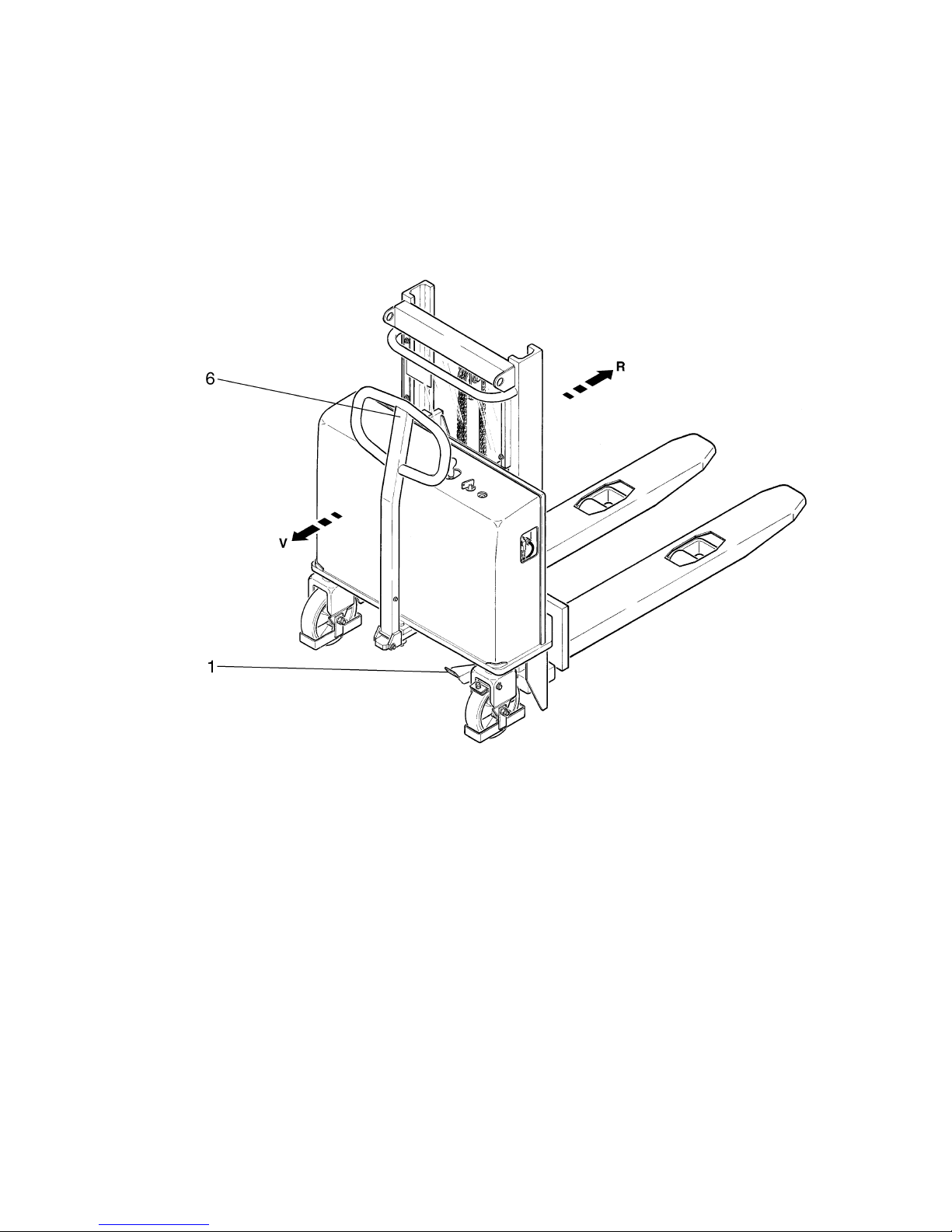
2 Description of the assemblies and functions
Item Designation
1 o
Battery monitor
2 t
Key switch
3 t
Operating lever, raise / lower fork
4 t Control shaft
5 t Hoist frame
6 t Load lifting device
7 t Load-bearing wheel arm
8 t Battery charge plug 230 VAC (integrated battery charger)
9 t
Wheel guard
10 t
Steering wheels
11 t
Parking brake
12 t
Brake pedal (parking brake)
t = Standard equipment o = Optional equipment
0502.GB
B 2
2 Description of the assemblies and functions
Item Designation
1 o
Battery monitor
2 t
Key switch
3 t
Operating lever, raise / lower fork
4 t Control shaft
5 t Hoist frame
6 t Load lifting device
7 t Load-bearing wheel arm
8 t Battery charge plug 230 VAC (integrated battery charger)
9 t
Wheel guard
10 t
Steering wheels
11 t
Parking brake
12 t
Brake pedal (parking brake)
t = Standard equipment o = Optional equipment
Page 10

B 3
0502.GB
2.1 Truck
Construction: The HC is a four-wheeled vehicle incorporating two steering wheels
(11) and two load-bearing wheel arms (8). An easily opened cover gives very good
access to all units. The operating controls are located on top of the cover.
Safety features:
– The wheel guard (9) protects the operator’s feet.
Operating controls and indicators: The operating controls for raising and lowering
the fork are located on the cover.
The vehicle is fitted with a battery monitor (1).
Steering system: The truck is steered using the control shaft (4). The steering range
is approx. 90° to either side. A connecting rod transfers the steering movements to
the two steering wheels.
Brake system: One of the steering wheels (10) is fitted with a parking brake (11)
which is operated by a brake pedal (12).
Hydraulic system: The functions raising and lowering are controlled using the operating lever (3). When the lifting function is activated, the pump unit starts up. Hydraulic
oil is pumped from the oil reservoir into the cylinder. The load lifting device 6) is lifted.
Electrical system: 24 Volt system.
B 3
0502.GB
2.1 Truck
Construction: The HC is a four-wheeled vehicle incorporating two steering wheels
(11) and two load-bearing wheel arms (8). An easily opened cover gives very good
access to all units. The operating controls are located on top of the cover.
Safety features:
– The wheel guard (9) protects the operator’s feet.
Operating controls and indicators: The operating controls for raising and lowering
the fork are located on the cover.
The vehicle is fitted with a battery monitor (1).
Steering system: The truck is steered using the control shaft (4). The steering range
is approx. 90° to either side. A connecting rod transfers the steering movements to
the two steering wheels.
Brake system: One of the steering wheels (10) is fitted with a parking brake (11)
which is operated by a brake pedal (12).
Hydraulic system: The functions raising and lowering are controlled using the oper-
ating lever (3). When the lifting function is activated, the pump unit starts up. Hydraulic
oil is pumped from the oil reservoir into the cylinder. The load lifting device 6) is lifted.
Electrical system: 24 Volt system.
Page 11

0502.GB
B 4
3 Technical data - standard version
A
Technical data specified according to VDI 2198.
Technical data are subject to alteration and additions.
3.1 Performance data for standard trucks
3.2 Dimensions
* Ast includes a safety distance of 200 mm
3.3 Batteries and motor output
f
It is essential that the battery type for the double hoist frame model is observed, as
the weight of the batteries acts as a counterweight and must be present in the vehicle.
Designation HC
Q Rated load capacity 1000 kg
C Load centre 600 mm
Lifting speed with / without load 8 / 10 cm/s
Lowering speed with / without load 27 / 15 cm/s
Designation HC single hoist
frame
HC double hoist
frame
h
1
Height 1295/1975/2175 1775/1975 mm
h2Free-lift - 175 mm
h
3
Lifting height 814/1514/1714 2414/2814 mm
h
4
Height, mast extended 1295/1995/2195 2910/3310 mm
h
13
Height, fork lowered 86 86 mm
s Thickness of fork 62 62 mm
y Wheel base, load part lowered 1055 1055 mm
l Fork length 1150 1150 mm
l
1
Truck length 1651 1651 mm
l
2
Front section length 501 501 mm
e Fork width 160 160 mm
b
1
Truck width 850 850 mm
b
5
Distance between the forks,
outside
520/560 520/560
mm
b
11
Track width of load section 400 400 mm
m2Ground clearance 24 24 mm
Wa Turning radius 1650 1650 mm
Ast* Aisle width
800x1200 in longitudinal dir.
3170 3170 mm
HC single hoist frame HC double hoist frame
Battery 2 x 12 V / 55 Ah in series 2 x 12 V / 110 Ah in series
Battery weight Approx. 2 x 17 kg Approx. 2 x 28 kg
Motor output,
S3 12%
1,8 kW 1,8 kW
Page 12

B 5
0502.GB
B 5
0502.GB
Page 13

0502.GB
B 6
3.4 EN standards
Continuous sound level: 61,0 dB(A)
according to prEN 12053 as stipulated in ISO 4871
A
The continuous sound level is a value averaged according to standard regulations,
taking the sound pressure level into account when driving, lifting and idling. The
sound pressure level is measured at the ear.
Electromagnetic compatibility (EMC)
The manufacturer confirms compliance with the limit values for electromagnetic emission and interference immunity as well as testing of static electricity discharge according to prEN 12895 and the references to other
standards contained therein.
A
Electrical or electronic components and their arrangement may only be modified after
written approval by the manufacturer has been obtained.
3.5 Conditions for application
Ambient temperature
- during operation: 0 °C to 40 °C
A
Industrial trucks must be specially equipped and approved for continuous use in environments with temperatures below 5°C or in cold stores respectively with extreme
temperatures or humidity changes.
0502.GB
B 6
3.4 EN standards
Continuous sound level: 61,0 dB(A)
according to prEN 12053 as stipulated in ISO 4871
A
The continuous sound level is a value averaged according to standard regulations,
taking the sound pressure level into account when driving, lifting and idling. The
sound pressure level is measured at the ear.
Electromagnetic compatibility (EMC)
The manufacturer confirms compliance with the limit va-
lues for electromagnetic emission and interference im-
munity as well as testing of static electricity discharge ac-
cording to prEN 12895 and the references to other
standards contained therein.
A
Electrical or electronic components and their arrangement may only be modified after
written approval by the manufacturer has been obtained.
3.5 Conditions for application
Ambient temperature
- during operation: 0 °C to 40 °C
A
Industrial trucks must be specially equipped and approved for continuous use in en-
vironments with temperatures below 5°C or in cold stores respectively with extreme
temperatures or humidity changes.
Page 14

B 7
0502.GB
4 Labels
Item Designation
13 Load capacity Q
max
14 Load diagram
15 Eye for crane loading
16 Danger: Risk of crushing
17 Do not ride on the lifting fork
18 Do not stand under the load.
19 Truck identification plate
B 7
0502.GB
4 Labels
Item Designation
13 Load capacity Q
max
14 Load diagram
15 Eye for crane loading
16 Danger: Risk of crushing
17 Do not ride on the lifting fork
18 Do not stand under the load.
19 Truck identification plate
Page 15
0502.GB
B 8
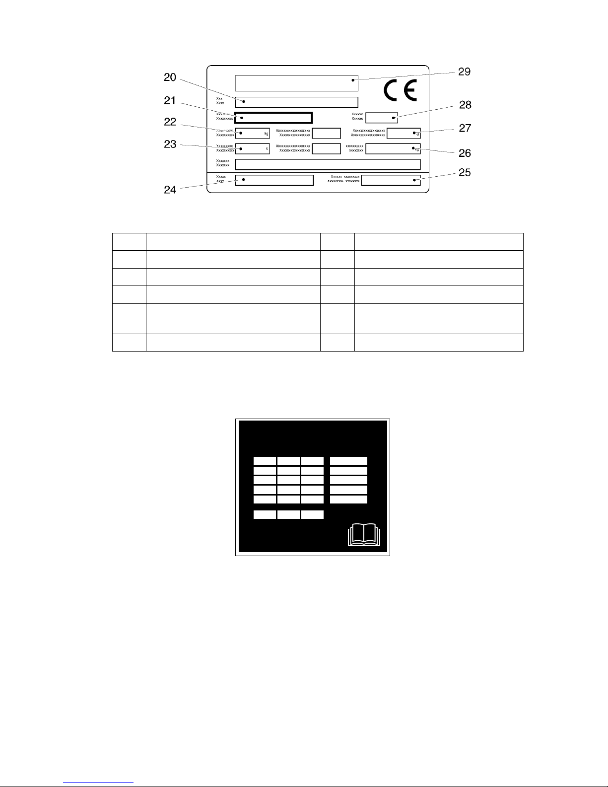
4.1 Truck identification plate
A
In the event of queries relating to the truck or spare part orders, please state the serial
no. (21) of the truck.
4.2 Load Diagram (14)
The load diagram gives the lifting capacity Q kg. of the vehicle when the hoist frame
is vertical. The maximum lifting capacity at a standardised load centre distance * C
(in mm) for a desired lifting height H (in mm) is shown in the form of a table.
*) The standardised load centre distance takes into account the width of the load as
well as its height.
Item Designation Item Designation
20 Type 25 Load centre distance in mm
21 Serial No. 26 Min./max. battery weight in kg
22 Rated capacity in kg 27 Empty weight without battery in kg
23 Battery: Voltage V
Ampere hours Ah
28 Year of manufacture
24 Manufacturer 29 Manufacturer logo
kg
mm
mm
066 594 000 F - D - GB - NL
Distance du centre de la charge
Lastschwerpunktabstand
Load centre distance
Zwaartepuntsafstand
Capacité
Tragfähigkeit
Capacity
Draagvermogen
Hauteur de levée
Hubhöhe
Lift height
Hefhoogte
0502.GB
B 8
4.1 Truck identification plate
A
In the event of queries relating to the truck or spare part orders, please state the serial
no. (21) of the truck.
4.2 Load Diagram (14)
The load diagram gives the lifting capacity Q kg. of the vehicle when the hoist frame
is vertical. The maximum lifting capacity at a standardised load centre distance * C
(in mm) for a desired lifting height H (in mm) is shown in the form of a table.
*) The standardised load centre distance takes into account the width of the load as
well as its height.
Item Designation Item Designation
20 Type 25 Load centre distance in mm
21 Serial No. 26 Min./max. battery weight in kg
22 Rated capacity in kg 27 Empty weight without battery in kg
23 Battery: Voltage V
Ampere hours Ah
28 Year of manufacture
24 Manufacturer 29 Manufacturer logo
kg
mm
mm
066 594 000 F - D - GB - NL
Distance du centre de la charge
Lastschwerpunktabstand
Load centre distance
Zwaartepuntsafstand
Capacité
Tragfähigkeit
Capacity
Draagvermogen
Hauteur de levée
Hubhöhe
Lift height
Hefhoogte
Page 16

C 16
0502.GB
C Transportation and commissioning
14 Transportation by crane
m
Only use lifting gear of adequate capacity
(loading weight = dead weight + battery weight; see truck identification plate).
A
Lifting points (1) are provided or loading the truck by means of crane gear.
– Park the truck and render it safe
(see chapter E).
– Attach the crane gear to the lifting eye
(1) (according to labelling).
m
The crane gear must be attached to the
lifting eye in such a manner that it
cannot slip!
The crane gear must be attached in
such a manner that it does not touch
any attachments during lifting.
15 Commissioning
To prepare the truck for operation after delivery or transportation, the following operations must be performed:
– Check the equipment for completeness.
– If necessary, install the battery. Make sure that the battery cable is not damaged.
– Charge the battery (see chapter D).
– Put the truck into operation in the stipulated manner (see chapter E).
A
When the truck is parked, the surface of the tyres may flatten. The flattening will disappear after the truck has been operated for a short time.
C 16
0502.GB
C Transportation and commissioning
14 Transportation by crane
m
Only use lifting gear of adequate capacity
(loading weight = dead weight + battery weight; see truck identification plate).
A
Lifting points (1) are provided or loading the truck by means of crane gear.
– Park the truck and render it safe
(see chapter E).
– Attach the crane gear to the lifting eye
(1) (according to labelling).
m
The crane gear must be attached to the
lifting eye in such a manner that it
cannot slip!
The crane gear must be attached in
such a manner that it does not touch
any attachments during lifting.
15 Commissioning
To prepare the truck for operation after delivery or transportation, the following ope-
rations must be performed:
– Check the equipment for completeness.
– If necessary, install the battery. Make sure that the battery cable is not damaged.
– Charge the battery (see chapter D).
– Put the truck into operation in the stipulated manner (see chapter E).
A
When the truck is parked, the surface of the tyres may flatten. The flattening will dis-
appear after the truck has been operated for a short time.
Page 17

0502GB
C 17
0502GB
C 17
Page 18

D 18
0502GB
D Battery-Servicing,recharging,replacement
14 Safety regulations governing the handling of lead-acid batteries
The truck must be parked and rendered safe before any operations on batteries are
undertaken (refer to chapter E).
Servicing staff: Recharging, servicing and replacing of batteries must only be performed by qualified personnel. The instructions contained in this operating manual,
and the instructions of the manufacturer of the battery and of the battery recharging
station, must be observed when performing the above operations.
Fire protection measures: Smoking and naked flames are not permitted when
handling batteries. No inflammable substances or spark-generating materials must
be present or stored within a distance of 2 meters of the truck parked for battery recharging. The location must be well ventilated and fire fighting equipment must be
kept ready.
Servicing of batteries: The battery cell screw caps must be kept dry and clean. Terminals and cable shoes must be clean, lightly greased with pole grease and must be
securely tightened. Batteries with bare terminal posts must be covered using a nonskid insulating mat.
Disposal of the battery: Batteries must only be disposed of as stipulated in the national environmental protection regulations or waste disposal provisions. The manufacturer’s specifications for the disposal must be heeded.
m
Before closing the battery hood, make sure that the battery cable cannot be damaged.
f
Batteries contain dissolved acid which is toxic and caustic. For this reason, protective
clothing and goggles must be worn whenever work is undertaken on batteries. Avoid
physical contact with battery acid.
If clothing, skin or eyes accidentally come into contact with battery acid, liberally flush
the affected parts with clean water. Consult a doctor when skin or eyes come into contact with battery acid. Spilled battery acid must be immediately neutralized.
m
Use only batteries of the correct capacity (see chapter B).
f
Battery weight and dimensions have considerable influence on operational safety of
the truck. Changing the battery equipment is not permitted without prior approval by
the manufacturer.
15 Battery types
m
Do not add distilled water if the vehicle is fitted with maintenance free batteries! The
covers of the cells are tightly closed. Opening the covers will destroy the battery! Ob-
serve the written instructions on the batteries.
The battery weight is given on the battery identification plate.
D 18
0502GB
D Battery-Servicing,recharging,replacement
14 Safety regulations governing the handling of lead-acid batteries
The truck must be parked and rendered safe before any operations on batteries are
undertaken (refer to chapter E).
Servicing staff: Recharging, servicing and replacing of batteries must only be per-
formed by qualified personnel. The instructions contained in this operating manual,
and the instructions of the manufacturer of the battery and of the battery recharging
station, must be observed when performing the above operations.
Fire protection measures: Smoking and naked flames are not permitted when
handling batteries. No inflammable substances or spark-generating materials must
be present or stored within a distance of 2 meters of the truck parked for battery re-
charging. The location must be well ventilated and fire fighting equipment must be
kept ready.
Servicing of batteries: The battery cell screw caps must be kept dry and clean. Ter-
minals and cable shoes must be clean, lightly greased with pole grease and must be
securely tightened. Batteries with bare terminal posts must be covered using a non-
skid insulating mat.
Disposal of the battery: Batteries must only be disposed of as stipulated in the na-
tional environmental protection regulations or waste disposal provisions. The manu-
facturer’s specifications for the disposal must be heeded.
m
Before closing the battery hood, make sure that the battery cable cannot be dama-
ged.
f
Batteries contain dissolved acid which is toxic and caustic. For this reason, protective
clothing and goggles must be worn whenever work is undertaken on batteries. Avoid
physical contact with battery acid.
If clothing, skin or eyes accidentally come into contact with battery acid, liberally flush
the affected parts with clean water. Consult a doctor when skin or eyes come into con-
tact with battery acid. Spilled battery acid must be immediately neutralized.
m
Use only batteries of the correct capacity (see chapter B).
f
Battery weight and dimensions have considerable influence on operational safety of
the truck. Changing the battery equipment is not permitted without prior approval by
the manufacturer.
15 Battery types
m
Do not add distilled water if the vehicle is fitted with maintenance free batteries! The
covers of the cells are tightly closed. Opening the covers will destroy the battery! Ob-
serve the written instructions on the batteries.
The battery weight is given on the battery identification plate.
Page 19
0502.GB
D 19
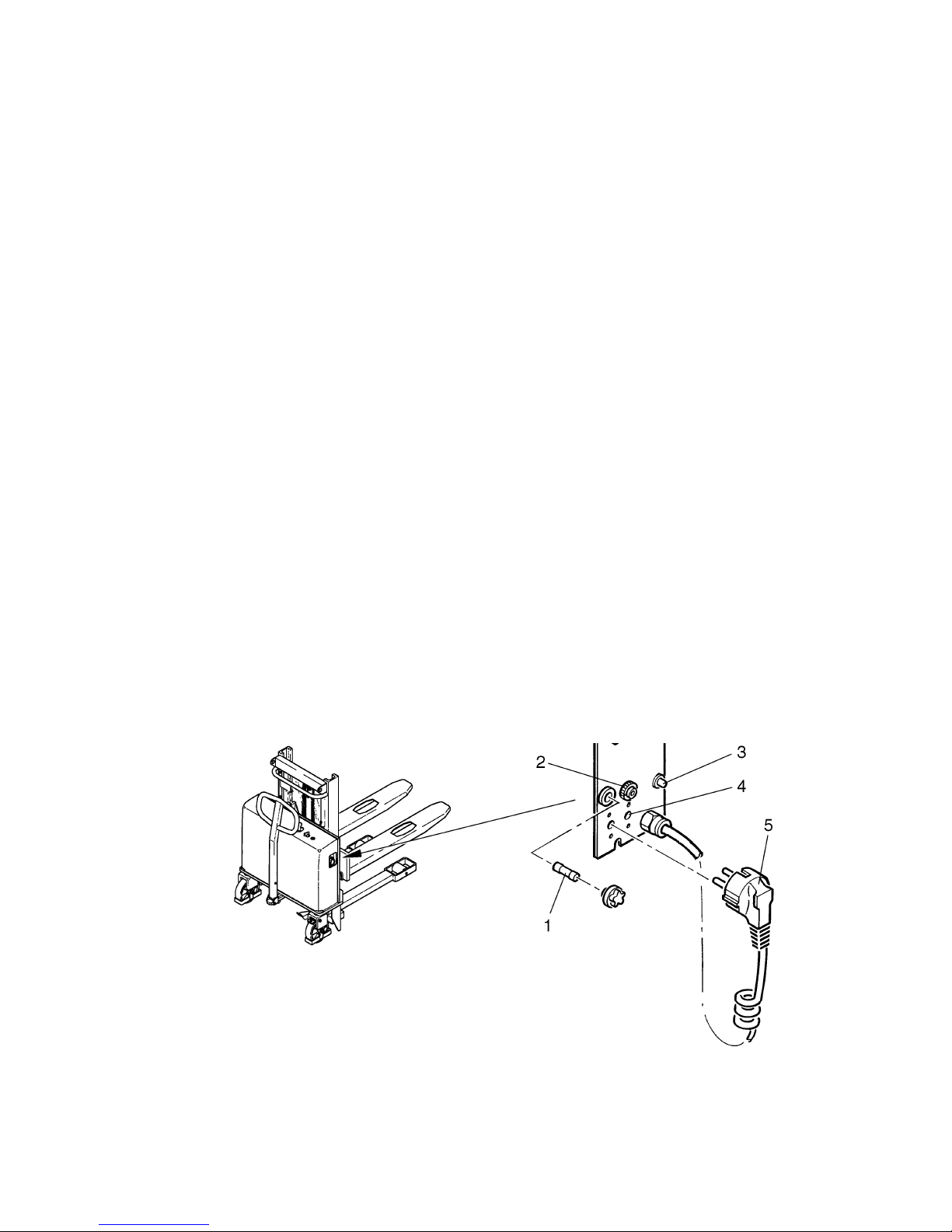
16 Charging the battery using the integrated charger
The mains cable of the charger is accessible from outside.
f
Do not remove the cover before or during the charging process. If the cover is open,
there is a risk of electrocution and danger to life.
f
It is essential to disconnect the vehicle from the mains electricity supply before changing the fuse (1).
m
It is advisable to charge the batteries whenever possible (for instance when the vehicle is not being used). This is easier on the batteries and the charging unit as these
are then deeply discharged less often. This extends the service life. Ensure that the
mains charging cable is stowed inside the cover to prevent damage, and to avoid the
cable being pulled off when the vehicle is put into operation.
A
The integrated battery charger charges the batteries on the principle of the falling WU
charging characteristic. The charging time for a battery which has been discharged
to the maximum limit of 80% is approximately 9 to 12 hours.
– Park the vehicle near to a suitable power outlet, and secure the vehicle (see chap-
ter E).
– Remove the mains plug (5) from its holder under the cover and connect it to the
mains electricity supply.
– If the battery is discharged, the LED (3) will light up and the charging process will
begin.
– When the battery is fully charged, the charger will automatically switch to disconti-
nuous charging, which continues for as long as the mains supply voltage is present.
The LED (3) now flashes on and off (we do not advise using the vehicle until this
point is reached).
– If the LED (3) goes out during the charging process, check whether mains voltage
is present and whether the magnetic cut-out switch (2) has tripped (if this is the
case turn it back on by resetting it).
Mains supply
Mains voltage: 230 V ±10% Mains frequency: 50 Hz ±4%
0502.GB
D 19
16 Charging the battery using the integrated charger
The mains cable of the charger is accessible from outside.
f
Do not remove the cover before or during the charging process. If the cover is open,
there is a risk of electrocution and danger to life.
f
It is essential to disconnect the vehicle from the mains electricity supply before chang-
ing the fuse (1).
m
It is advisable to charge the batteries whenever possible (for instance when the vehi-
cle is not being used). This is easier on the batteries and the charging unit as these
are then deeply discharged less often. This extends the service life. Ensure that the
mains charging cable is stowed inside the cover to prevent damage, and to avoid the
cable being pulled off when the vehicle is put into operation.
A
The integrated battery charger charges the batteries on the principle of the falling WU
charging characteristic. The charging time for a battery which has been discharged
to the maximum limit of 80% is approximately 9 to 12 hours.
– Park the vehicle near to a suitable power outlet, and secure the vehicle (see chap-
ter E).
– Remove the mains plug (5) from its holder under the cover and connect it to the
mains electricity supply.
– If the battery is discharged, the LED (3) will light up and the charging process will
begin.
– When the battery is fully charged, the charger will automatically switch to disconti-
nuous charging, which continues for as long as the mains supply voltage is present.
The LED (3) now flashes on and off (we do not advise using the vehicle until this
point is reached).
– If the LED (3) goes out during the charging process, check whether mains voltage
is present and whether the magnetic cut-out switch (2) has tripped (if this is the
case turn it back on by resetting it).
Mains supply
Mains voltage: 230 V ±10% Mains frequency: 50 Hz ±4%
Page 20
D 20
0502GB
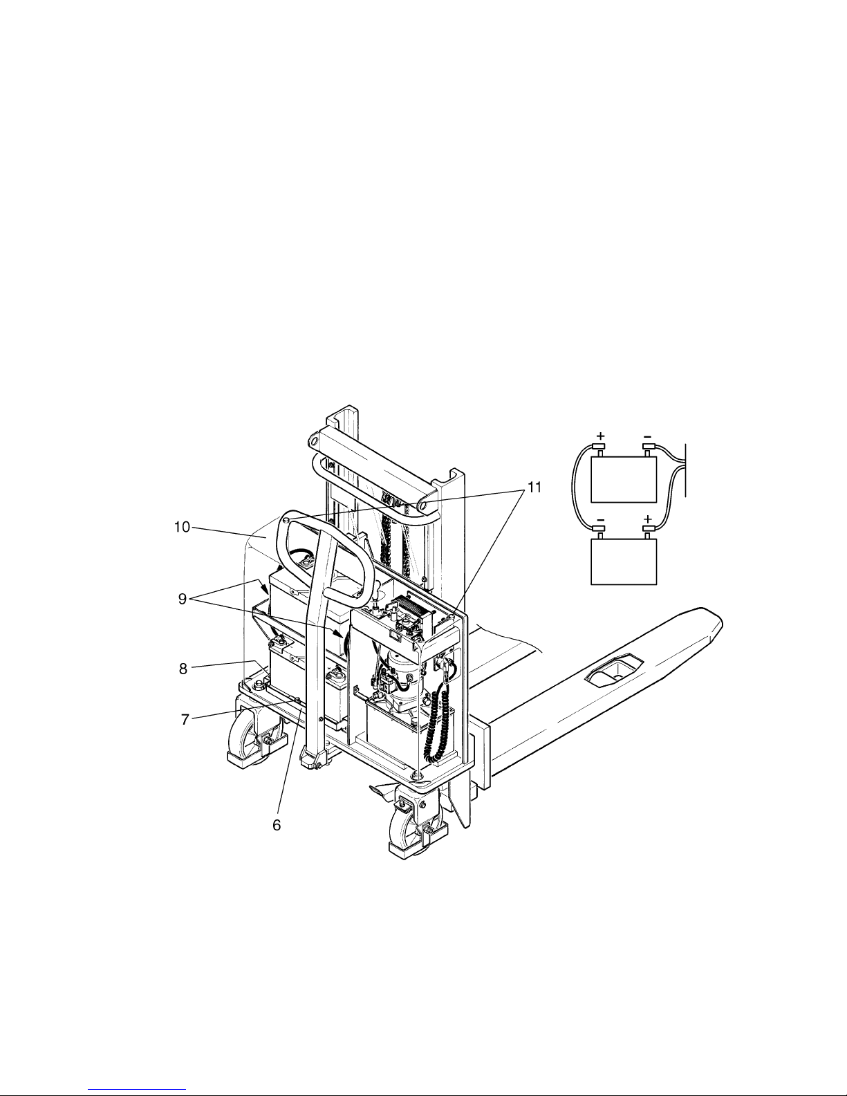
17 Replacing the batteries
– Park the vehicle and secure it (see chapter E).
– Loosen the screws (11) and lift off the cover (10) (allen key is supplied).
m
Route the battery cables in such a way that they do not catch on the battery when it
is lifted out.
Upper battery:
– Unscrew the battery fixtures (9); there are 4 screws.
– Undo the terminal screws and pull the battery cables off of the terminals.
– Lift out the upper battery.
Lower battery:
– Loosen (do not remove completely) the screws (8) securing the battery platform (6)
and pull the platform together with the battery forward.
– Undo the lower battery fixtures (7); there is one nut to be undone.
– Undo the terminal screws and pull the battery cables off of the terminals.
– Lift out the lower battery.
m
Re-assemble in reverse order; ensure that the batteries are correctly orientated and
that the electrical connections are correctly made (see diagram).
– After the battery has been reinstalled, check all cable connections and plugged
connections for visible damage.
Connection Diagram
D 20
0502GB
17 Replacing the batteries
– Park the vehicle and secure it (see chapter E).
– Loosen the screws (11) and lift off the cover (10) (allen key is supplied).
m
Route the battery cables in such a way that they do not catch on the battery when it
is lifted out.
Upper battery:
– Unscrew the battery fixtures (9); there are 4 screws.
– Undo the terminal screws and pull the battery cables off of the terminals.
– Lift out the upper battery.
Lower battery:
– Loosen (do not remove completely) the screws (8) securing the battery platform (6)
and pull the platform together with the battery forward.
– Undo the lower battery fixtures (7); there is one nut to be undone.
– Undo the terminal screws and pull the battery cables off of the terminals.
– Lift out the lower battery.
m
Re-assemble in reverse order; ensure that the batteries are correctly orientated and
that the electrical connections are correctly made (see diagram).
– After the battery has been reinstalled, check all cable connections and plugged
connections for visible damage.
Connection Diagram
Page 21

0502.GB
D 21
18 Battery Monitor (o)
The charge status of the battery is shown by the
light-emitting diode (12) once the key switch has
been turned on.
Light-emitting diode (12) steady green:
– Normal condition, battery voltage 1,7 V per cell.
Light-emitting diode (12) flashes red:
– It is recommended that the batteries be
charged; battery voltage is between 1,7 V and
1,5 V per cell.
Light-emitting diode (12) steady red:
– It is essential that the batteries are charged, battery voltage is < 1,5 V per cell.
12
Page 22

E 1
0502.GB
E Operation
1 Safety regulations governing the operation of the fork lift truck
Driving permission: The fork lift truck must only be operated by persons who have
been trained in the operation of trucks, who have demonstrated to the user or his representative their capability of moving and handling loads, and who have expressly
been charged by the user or his representative with the operation of the truck.
Rights, duties and conduct of the driver: The driver must be: informed of his rights
and duties; trained in the operation of the fork lift truck; and familiar with the contents
of these operating instructions. All necessary rights must be granted to him. If the fork
lift truck can be used in the pedestrian-controlled mode, the driver must wear safety
boots when operating the truck.
Prohibition of unauthorised use: The driver is responsible for the fork lift truck during working time. He must forbid unauthorised persons to drive or operate the fork
lift truck. The transport or lifting of persons is forbidden.
Damage and defects: Damage or defects noted on the fork lift truck or on the attachments must immediately be brought to the notice of the person in charge. fork lift
trucks that cannot be safely operated (e.g. due to worn tyres or defective brakes)
must not be used until they have been properly repaired.
Repairs: Without specific training and express authorisation, the driver is not allowed
to perform any repairs or modifications on the fork lift truck. Under no circumstances
must the driver change the setting of switches or safety installations or render them
ineffective.
Danger area: A “danger area” is considered to be the area within which persons are
endangered by the travelling or lifting movements of the fork lift truck or its load lifting
devices (e.g. fork or attachments), or by the loads being transported. This also includes the area within reach of falling loads or falling / lowering truck attachments.
f
Unauthorised persons must be asked to leave the danger area. The driver must give
a warning signal whenever a situation presenting danger to persons might develop.
The fork lift truck must immediately be brought to a standstill if persons, although asked, do not leave the danger area.
Safety devices and warning labels: The safety devices, warning labels and warning
notes described in the present operating instructions must always be heeded.
E 1
0502.GB
E Operation
1 Safety regulations governing the operation of the fork lift truck
Driving permission: The fork lift truck must only be operated by persons who have
been trained in the operation of trucks, who have demonstrated to the user or his re-
presentative their capability of moving and handling loads, and who have expressly
been charged by the user or his representative with the operation of the truck.
Rights, duties and conduct of the driver: The driver must be: informed of his rights
and duties; trained in the operation of the fork lift truck; and familiar with the contents
of these operating instructions. All necessary rights must be granted to him. If the fork
lift truck can be used in the pedestrian-controlled mode, the driver must wear safety
boots when operating the truck.
Prohibition of unauthorised use: The driver is responsible for the fork lift truck du-
ring working time. He must forbid unauthorised persons to drive or operate the fork
lift truck. The transport or lifting of persons is forbidden.
Damage and defects: Damage or defects noted on the fork lift truck or on the attach-
ments must immediately be brought to the notice of the person in charge. fork lift
trucks that cannot be safely operated (e.g. due to worn tyres or defective brakes)
must not be used until they have been properly repaired.
Repairs: Without specific training and express authorisation, the driver is not allowed
to perform any repairs or modifications on the fork lift truck. Under no circumstances
must the driver change the setting of switches or safety installations or render them
ineffective.
Danger area: A “danger area” is considered to be the area within which persons are
endangered by the travelling or lifting movements of the fork lift truck or its load lifting
devices (e.g. fork or attachments), or by the loads being transported. This also inclu-
des the area within reach of falling loads or falling / lowering truck attachments.
f
Unauthorised persons must be asked to leave the danger area. The driver must give
a warning signal whenever a situation presenting danger to persons might develop.
The fork lift truck must immediately be brought to a standstill if persons, although as-
ked, do not leave the danger area.
Safety devices and warning labels: The safety devices, warning labels and warning
notes described in the present operating instructions must always be heeded.
Page 23
0502.GB
E 2
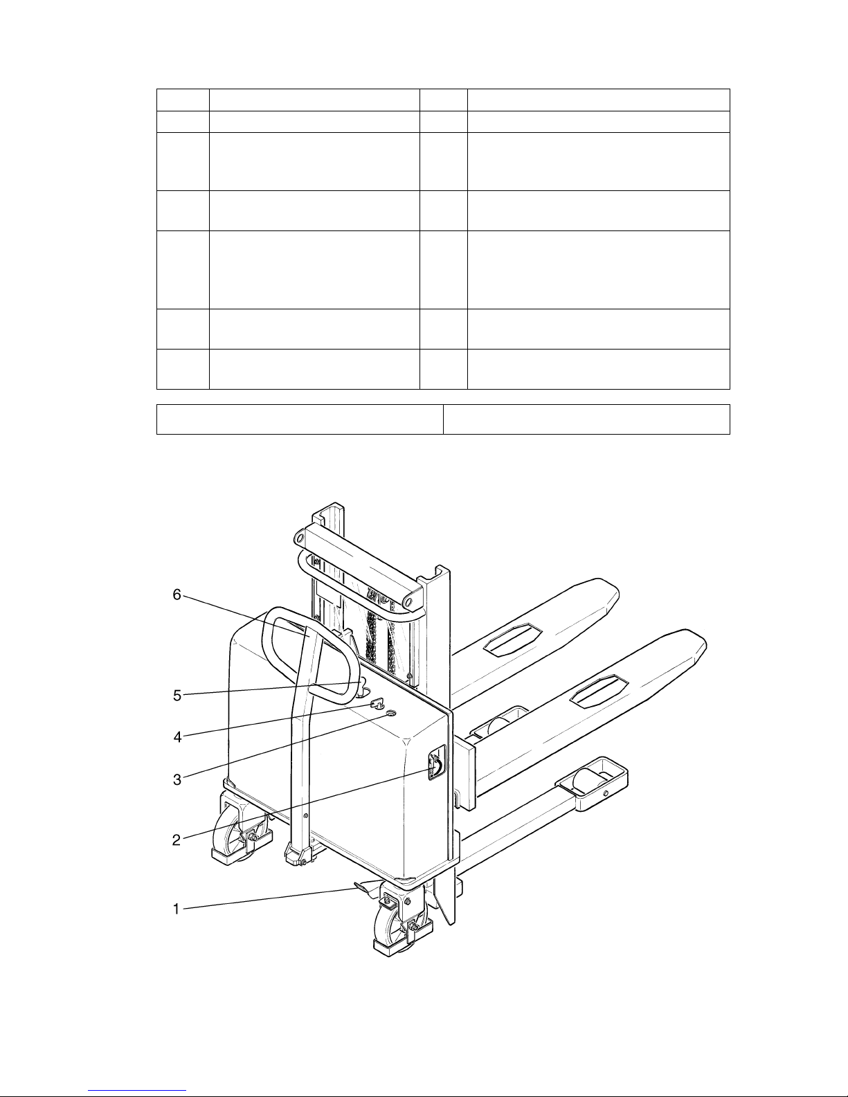
2 Description of the operating controls and indicators
Item Control or indicator Function
1 Brake pedal t Prevents the vehicle rolling.
2 Integrated charger
(incl. safety cut-out)
t
The battery is charged when the
mains plug is plugged into an electric
outlet.
3 Battery monitor o Shows the charging condition of the
battery (refer to chapter D).
4 Key swith t For switching the control current on
and off.
Prevents unauthorised use of the ve-
hicle.
5 Operating lever, raise / lower
fork.
t Raises or lowers the fork
6 Control shaft t Moves vehicle forwards and back-
wards and steers vehicle.
t = Standard equipment o = Optional equipment
0502.GB
E 2
2 Description of the operating controls and indicators
Item Control or indicator Function
1 Brake pedal t Prevents the vehicle rolling.
2 Integrated charger
(incl. safety cut-out)
t
The battery is charged when the
mains plug is plugged into an electric
outlet.
3 Battery monitor o Shows the charging condition of the
battery (refer to chapter D).
4 Key swith t For switching the control current on
and off.
Prevents unauthorised use of the ve-
hicle.
5 Operating lever, raise / lower
fork.
t Raises or lowers the fork
6 Control shaft t Moves vehicle forwards and back-
wards and steers vehicle.
t = Standard equipment o = Optional equipment
Page 24

E 3
0502.GB
3 Starting up the truck
f
The driver must make sure that nobody is within the danger area of the truck before
the truck is switch on or operated or before a load is lifted.
Checks and operations to be performed before starting daily work
– Check the entire truck (especially the wheels and the load lifting device) for dama-
ge.
Switching on the truck
– Check whether the charging cable is connected and finish charging procedure if ne-
cessary (see chapter D9).
– Insert the key into the key switch (4) and turn it clockwise as far as it will go.
A
The discharge control LED (discharge indicator) (3) shows the present battery capacity.
– Check whether the fork can be raised and lowered, by using the operating lever (5).
– Check that the brake works (see section 4.2).
The truck is now ready for operation.
E 3
0502.GB
3 Starting up the truck
f
The driver must make sure that nobody is within the danger area of the truck before
the truck is switch on or operated or before a load is lifted.
Checks and operations to be performed before starting daily work
– Check the entire truck (especially the wheels and the load lifting device) for dama-
ge.
Switching on the truck
– Check whether the charging cable is connected and finish charging procedure if ne-
cessary (see chapter D9).
– Insert the key into the key switch (4) and turn it clockwise as far as it will go.
A
The discharge control LED (discharge indicator) (3) shows the present battery capa-
city.
– Check whether the fork can be raised and lowered, by using the operating lever (5).
– Check that the brake works (see section 4.2).
The truck is now ready for operation.
Page 25

0502.GB
E 4
4 Operation of the fork lift truck
4.1 Safety regulations applicable when operating the truck
Driving lanes and work areas: Only such lanes and routes that are specially alloca-
ted for truck traffic must be used. Unauthorized persons must stay away from work
areas. Loads must only be stored at places specially provided for this purpose.
Driving conduct: The travelling speed must be adapted to the prevailing local conditions. The truck must be driven at slow speed when negotiating bends or narrow
passages, when passing through swing doors and at blind spots. The driver must always observe an adequate braking distance between the fork lift truck and the vehicle
in front and he must be in control of his truck at all times. Sudden stopping (except in
emergencies), rapid U-turns and overtaking at dangerous or blind spots is not permitted. It is forbidden to lean out of or reach beyond the working and operating area.
Visibility: The driver must look in the direction of travel and must always have a clear
view of the route ahead. When loads blocking the view are carried, the fork lift truck
must be driven with the load at the rear. If this is not possible, a second person must
walk in front of the fork lift truck to give suitable warnings.
Negotiating slopes and inclines: Negotiating of slopes and inclines is permitted
only when they are recognised lanes, when they are clean and non-slipping, and
when the technical specification of the truck permits safe driving on such slopes or
inclines. Loads must always be carried at that end of the truck facing uphill. U-turns,
cutting obliquely over slopes or inclines and parking of the fork lift truck on slopes or
inclines is not permitted. Inclines must only be negotiated at slow speed, with the
driver ready to brake at any moment.
Use of lifts and driving on loading platforms: Lifts and loading platforms must only
be used if they are of adequate load bearing capacity, if suitable for driving on, and if
authorised by the user of the truck for truck traffic. The fork lift truck driver has to satisfy himself accordingly before driving into lifts or on to loading platforms. The truck
must enter lifts with the load in front and must take up a position which does not allow
it to come into contact with the walls of the lift shaft. Persons riding in the lift together
with the fork lift truck must only enter the lift after the fork lift truck has come safely to
a standstill, and must leave the lift before the fork lift truck.
Nature of the loads carried: Only loads that have been safely and correctly secured
must be carried. Never transport loads stacked higher than the top of the fork carriage, or stacked higher than the guard grille.
Transporting liquids: when transporting liquids, the centre of gravity can change,
depending upon the attitude of the vehicle and can considerably affect stability. For
this reason all possible precautions are to be taken, in particular avoiding sudden
movements when accelerating, braking and when negotiating bends.
0502.GB
E 4
4 Operation of the fork lift truck
4.1 Safety regulations applicable when operating the truck
Driving lanes and work areas: Only such lanes and routes that are specially alloca-
ted for truck traffic must be used. Unauthorized persons must stay away from work
areas. Loads must only be stored at places specially provided for this purpose.
Driving conduct: The travelling speed must be adapted to the prevailing local con-
ditions. The truck must be driven at slow speed when negotiating bends or narrow
passages, when passing through swing doors and at blind spots. The driver must al-
ways observe an adequate braking distance between the fork lift truck and the vehicle
in front and he must be in control of his truck at all times. Sudden stopping (except in
emergencies), rapid U-turns and overtaking at dangerous or blind spots is not permit-
ted. It is forbidden to lean out of or reach beyond the working and operating area.
Visibility: The driver must look in the direction of travel and must always have a clear
view of the route ahead. When loads blocking the view are carried, the fork lift truck
must be driven with the load at the rear. If this is not possible, a second person must
walk in front of the fork lift truck to give suitable warnings.
Negotiating slopes and inclines: Negotiating of slopes and inclines is permitted
only when they are recognised lanes, when they are clean and non-slipping, and
when the technical specification of the truck permits safe driving on such slopes or
inclines. Loads must always be carried at that end of the truck facing uphill. U-turns,
cutting obliquely over slopes or inclines and parking of the fork lift truck on slopes or
inclines is not permitted. Inclines must only be negotiated at slow speed, with the
driver ready to brake at any moment.
Use of lifts and driving on loading platforms: Lifts and loading platforms must only
be used if they are of adequate load bearing capacity, if suitable for driving on, and if
authorised by the user of the truck for truck traffic. The fork lift truck driver has to sa-
tisfy himself accordingly before driving into lifts or on to loading platforms. The truck
must enter lifts with the load in front and must take up a position which does not allow
it to come into contact with the walls of the lift shaft. Persons riding in the lift together
with the fork lift truck must only enter the lift after the fork lift truck has come safely to
a standstill, and must leave the lift before the fork lift truck.
Nature of the loads carried: Only loads that have been safely and correctly secured
must be carried. Never transport loads stacked higher than the top of the fork carria-
ge, or stacked higher than the guard grille.
Transporting liquids: when transporting liquids, the centre of gravity can change,
depending upon the attitude of the vehicle and can considerably affect stability. For
this reason all possible precautions are to be taken, in particular avoiding sudden
movements when accelerating, braking and when negotiating bends.
Page 26
E 5
0502.GB
4.2 Driving, steering, braking
f
It is not admissible to stay on the vehicle during driving.
Driving
m
Only drive with the hoods closed and properly locked.
– Start up the truck (see section 3).
– Tilt the control shaft (6) downwards and move it in the desired direction by either
pulling the vehicle forwards (V) or pushing it backwards (R).
Steering
– Swivel the control shaft (6) to the left or the right.
m
In narrow bends, the control shaft protrudes beyond the truck contour!
Braking
f
The vehicle’s braking distance depends to a great extent upon the nature of the floor
surface. The operator is to take this into account when moving the vehicle.
The truck can be braked in two ways:
– By hand (by pushing or pulling against the direction of motion).
– Brake pedal (parking brake only).
Page 27

0502.GB
E 6
4.3 Picking up and setting down loads
m
Before picking up a load, the driver must make sure that the load rests properly on its
pallet and that it does not exceed the maximum load capacity of the truck.
Picking up long loads crosswise is not permitted.
– Move the truck so that the load lifting device passes completely below the load.
Lifting
– Move the operating lever raise / lower fork (5)
to “H” until the desired height has been
reached.
Lowering
– Move the operating lever raise / lower fork (5)
to “S” until the desired height has been
reached.
4.4 Parking the truck and rendering it safe
f
Always render the truck safe when parking it.
Do not park the truck on slopes.
The load lifting device must always be completely lowered.
– Lower the load lifting device.
– Turn the key (4) to the vertical position and remove it.
– Apply the brake using the pedal (1).
Page 28

F 1
0708.GB
F Maintenance of the fork-lift truck
1 Operational safety and environmental protection
The checks and servicing operations contained in this chapter must be performed in
accordance with the intervals as indicated in the servicing checklists.
f
Modifications of fork-lift truck assemblies, especially of the safety installations, are not
permitted. On no account must the operational speeds of the truck be changed.
m
Only original spare parts have been certified by our quality assurance service. To ensure safe and reliable operation of the fork-lift truck, only spare parts of the manufacturer must be used. Used parts, oils and fuels must be disposed of in accordance with
the applicable environmental protection regulations. For oil changes, the oil service
of the manufacturer is available to you.
Upon completion of any checking and servicing activities, the operations contained in
the section “Recommissioning” must be performed (see section F).
2 Safety regulations applicable to truck maintenance
Servicing and maintenance personnel: The fork-lift truck must only be serviced
and maintained by trained personnel of the manufacturer. The service organization
of the manufacturer has external technicians trained especially for these assignments. We thus recommend signing a maintenance contract with the relevant service
location of the manufacturer.
Lifting and jacking up: When a fork-lift truck is to be lifted, the lifting gear must only
be secured to the points specially provided for this purpose. When the truck is to be
jacked up, suitable measures must be taken to prevent the truck from slipping or tipping over (use of wedges, wooden blocks). Work underneath the raised load lifting
device must only be carried out when the fork is immobilised and supported by a
chain of adequate strength.
Cleaning operations: No inflammable liquids must be used when cleaning the forklift truck. Prior to commencing cleaning operations, all safety measures that are required to prevent sparking (e.g. by short-circuits) have to be taken. In the case of battery driven vehicles, remove the battery cable or ensure that the batteries are disconnected. Only weak indraft, weak compressed air and non-conducting, antistatic
brushes must be used for the cleaning of electric or electronic assemblies.
m
If the fork-lift truck is to be cleaned using a water jet or a high-pressure cleaner, all
electric and electronic components must be carefully covered beforehand because
moisture can lead to incorrect functioning.
Cleaning by means of a steam jet is not permitted.
Upon completion of cleaning work, the operations detailed in the section “Recommissioning” must be performed.
F 1
0708.GB
F Maintenance of the fork-lift truck
1 Operational safety and environmental protection
The checks and servicing operations contained in this chapter must be performed in
accordance with the intervals as indicated in the servicing checklists.
f
Modifications of fork-lift truck assemblies, especially of the safety installations, are not
permitted. On no account must the operational speeds of the truck be changed.
m
Only original spare parts have been certified by our quality assurance service. To en-
sure safe and reliable operation of the fork-lift truck, only spare parts of the manufac-
turer must be used. Used parts, oils and fuels must be disposed of in accordance with
the applicable environmental protection regulations. For oil changes, the oil service
of the manufacturer is available to you.
Upon completion of any checking and servicing activities, the operations contained in
the section “Recommissioning” must be performed (see section F).
2 Safety regulations applicable to truck maintenance
Servicing and maintenance personnel: The fork-lift truck must only be serviced
and maintained by trained personnel of the manufacturer. The service organization
of the manufacturer has external technicians trained especially for these assign-
ments. We thus recommend signing a maintenance contract with the relevant service
location of the manufacturer.
Lifting and jacking up: When a fork-lift truck is to be lifted, the lifting gear must only
be secured to the points specially provided for this purpose. When the truck is to be
jacked up, suitable measures must be taken to prevent the truck from slipping or tip-
ping over (use of wedges, wooden blocks). Work underneath the raised load lifting
device must only be carried out when the fork is immobilised and supported by a
chain of adequate strength.
Cleaning operations: No inflammable liquids must be used when cleaning the fork-
lift truck. Prior to commencing cleaning operations, all safety measures that are re-
quired to prevent sparking (e.g. by short-circuits) have to be taken. In the case of bat-
tery driven vehicles, remove the battery cable or ensure that the batteries are discon-
nected. Only weak indraft, weak compressed air and non-conducting, antistatic
brushes must be used for the cleaning of electric or electronic assemblies.
m
If the fork-lift truck is to be cleaned using a water jet or a high-pressure cleaner, all
electric and electronic components must be carefully covered beforehand because
moisture can lead to incorrect functioning.
Cleaning by means of a steam jet is not permitted.
Upon completion of cleaning work, the operations detailed in the section “Recommis-
sioning” must be performed.
Page 29

0708.GB
F 2
Work on the electric system: Work on the electric system of the truck must only be
performed by personnel specially trained for such operations. Before commencing
any work on the electric system, all measures required to prevent electric shocks
have to be taken. In the case of battery driven vehicles, the battery plug is to be disconnected additionally or the batteries are to be disconnected to ensure that the vehicle is electrically isolated.
Welding operations: To prevent any damage to electric or electronic com-ponents,
these have to be removed from the fork-lift truck before any welding operations are
undertaken.
Settings: When repairing or replacing hydraulic, electric or electronic compo-nents
or assemblies, all truck-specific settings have to be retained.
Tyres: The quality of the tyres greatly affects the stability and the driving behaviour
of the fork-lift truck. The factory-mounted tyres must only be replaced by original spare parts of the manufacturer, since otherwise the specification of the data sheet
cannot be met. When replacing wheels or tyres, it must be ensured that the fork-lift
truck remains level (tyres and wheels must always be replaced in pairs, i.e. left and
right together).
Lift chains: The lift chains wear rapidly if not lubricated. The intervals in the service
checklist apply to normal duty. If requirements are higher (dust, temperature), lubrication is required more often. The specified chain spray must be used as specified.
The external application of grease does not provide sufficient lubrication.
Hydraulic hoses: The hoses must be renewed every six years. When replacing hydraulic components, also renew the hoses in this hydraulic system.
0708.GB
F 2
Work on the electric system: Work on the electric system of the truck must only be
performed by personnel specially trained for such operations. Before commencing
any work on the electric system, all measures required to prevent electric shocks
have to be taken. In the case of battery driven vehicles, the battery plug is to be dis-
connected additionally or the batteries are to be disconnected to ensure that the ve-
hicle is electrically isolated.
Welding operations: To prevent any damage to electric or electronic com-ponents,
these have to be removed from the fork-lift truck before any welding operations are
undertaken.
Settings: When repairing or replacing hydraulic, electric or electronic compo-nents
or assemblies, all truck-specific settings have to be retained.
Tyres: The quality of the tyres greatly affects the stability and the driving behaviour
of the fork-lift truck. The factory-mounted tyres must only be replaced by original spa-
re parts of the manufacturer, since otherwise the specification of the data sheet
cannot be met. When replacing wheels or tyres, it must be ensured that the fork-lift
truck remains level (tyres and wheels must always be replaced in pairs, i.e. left and
right together).
Lift chains: The lift chains wear rapidly if not lubricated. The intervals in the service
checklist apply to normal duty. If requirements are higher (dust, temperature), lubri-
cation is required more often. The specified chain spray must be used as specified.
The external application of grease does not provide sufficient lubrication.
Hydraulic hoses: The hoses must be renewed every six years. When replacing hy-
draulic components, also renew the hoses in this hydraulic system.
Page 30

F 3
0708.GB
3 Maintenance and Inspection
One of the most important factors for the safe operation of the vehicle is a thorough
and competent maintenance service. If regular maintenance is neglected, the vehicle
may suffer breakdowns and in addition it creates a potential source of danger for the
personnel and the workplace.
m
The maintenance intervals given assume single-shift operation and normal working
conditions. These intervals are to be shortened as appropriate where higher demands are placed on the vehicle such as a very dusty environment, large variations
in temperature or multiple-shift operation.
The following maintenance checklist details the measures to be taken and when
these are to be carried out. The maintenance intervals are defined as follows:
W1 = Every 50 operational hours, or once a week at the latest.
W2 = Every 250 operational hours, or once every 4 weeks at the latest.
M3 = Every 500 operational hours, or once every 3 months at the latest.
M6 = Every 1000 operational hours, or once every 6 months at the latest.
M12 = Every 2000 operational hours, or once every 12 months at the latest.
A
W1 service intervals are to be performed by the customer.
In the run-in period - after approx. 100 service hours - or after repair work, the owner
must check the wheel nuts/bolts and re-tighten if necessary.
F 3
0708.GB
3 Maintenance and Inspection
One of the most important factors for the safe operation of the vehicle is a thorough
and competent maintenance service. If regular maintenance is neglected, the vehicle
may suffer breakdowns and in addition it creates a potential source of danger for the
personnel and the workplace.
m
The maintenance intervals given assume single-shift operation and normal working
conditions. These intervals are to be shortened as appropriate where higher de-
mands are placed on the vehicle such as a very dusty environment, large variations
in temperature or multiple-shift operation.
The following maintenance checklist details the measures to be taken and when
these are to be carried out. The maintenance intervals are defined as follows:
W1 = Every 50 operational hours, or once a week at the latest.
W2 = Every 250 operational hours, or once every 4 weeks at the latest.
M3 = Every 500 operational hours, or once every 3 months at the latest.
M6 = Every 1000 operational hours, or once every 6 months at the latest.
M12 = Every 2000 operational hours, or once every 12 months at the latest.
A
W1 service intervals are to be performed by the customer.
In the run-in period - after approx. 100 service hours - or after repair work, the owner
must check the wheel nuts/bolts and re-tighten if necessary.
Page 31

0708.GB
F 4
4 Maintenance checklist
Maintenance intervals
Standard = t WWMMM
Cold store
= k 123612
Chassis /
superstructure:
1.1 Check all load bearing elements for damage ttttt
1.2 Check all bolted connections ttttt
Wheels:
3.1 Check for wear and damage ttttt
3.2 Check the wheel bearings and ensure secure fastening of
wheels
tttt
Steering: 4.1 Check play. tttt
4.2 Check steering for functionality and adjustment, lubricate if
necessary.
tttt
Brake
system:
5.1 Performance and adjustment check ttttt
5.2 Check release functionality. ttttt
5.3 Check brake pad wear. tttt
Hydraulic
system:
6.1 Performance check tttt
6.2 Check hoses and connections for leaks and damage. tttt
6.3 Check hydraulic cylinder for leaks and damage. Check hydraulic cylinder mountings.
tttt
6.4 Check the oil level tttt
6.5 Change hydraulic oil and filter. t
6.6 Check functionality of the pressure-limiting valves. tttt
Electrical
system:
7.1 Check that connections are properly seated. tttt
7.2 Check cable for tight seating of connections and for
damage
tttt
7.3 Check the fuses for correct amperage tttt
7.4 Check that the switches and switch cams are properly seated and work correctly.
tttt
Batteries:
9.1 Check specific gravity of acid, acid level and cell voltage*
*) Does not apply to maintenance free batteries.
ttttt
9.2 Check the terminals for secure attachment and apply
grease
ttttt
9.3 Clean battery terminal connections and check that they are
firmly seated.
ttttt
9.4 Check that the cables are in order and replace if necessary. ttttt
9.5 Check that the battery is properly secured. tttt
Hoist frame: 10.1 Check for functionality and wear, readjust if necessary. tttt
10.2 Check the condition of the rollers and connecting rods. ttttt
10.3 Check that the fork is in order. ttttt
Lubrication: 11.1 Lubricate the vehicle according to the lubrication schedule. tttt
General
checks:
12.1 Check lifting and lowering speed ttt
Technial
check:
13.1 Test the machine with nominal load. ttt
0708.GB
F 4
4 Maintenance checklist
Maintenance intervals
Standard = t WWMMM
Cold store
= k 123612
Chassis /
super-
structure:
1.1 Check all load bearing elements for damage ttttt
1.2 Check all bolted connections ttttt
Wheels:
3.1 Check for wear and damage ttttt
3.2 Check the wheel bearings and ensure secure fastening of
wheels
tttt
Steering: 4.1 Check play. tttt
4.2 Check steering for functionality and adjustment, lubricate if
necessary.
tttt
Brake
system:
5.1 Performance and adjustment check ttttt
5.2 Check release functionality. ttttt
5.3 Check brake pad wear. tttt
Hydraulic
system:
6.1 Performance check tttt
6.2 Check hoses and connections for leaks and damage. tttt
6.3 Check hydraulic cylinder for leaks and damage. Check hy-
draulic cylinder mountings.
tttt
6.4 Check the oil level tttt
6.5 Change hydraulic oil and filter. t
6.6 Check functionality of the pressure-limiting valves. tttt
Electrical
system:
7.1 Check that connections are properly seated. tttt
7.2 Check cable for tight seating of connections and for
damage
tttt
7.3 Check the fuses for correct amperage tttt
7.4 Check that the switches and switch cams are properly sea-
ted and work correctly.
tttt
Batteries:
9.1 Check specific gravity of acid, acid level and cell voltage*
*) Does not apply to maintenance free batteries.
ttttt
9.2 Check the terminals for secure attachment and apply
grease
ttttt
9.3 Clean battery terminal connections and check that they are
firmly seated.
ttttt
9.4 Check that the cables are in order and replace if necessary. ttttt
9.5 Check that the battery is properly secured. tttt
Hoist frame: 10.1 Check for functionality and wear, readjust if necessary. tttt
10.2 Check the condition of the rollers and connecting rods. ttttt
10.3 Check that the fork is in order. ttttt
Lubrication: 11.1 Lubricate the vehicle according to the lubrication schedule. tttt
General
checks:
12.1 Check lifting and lowering speed ttt
Technial
check:
13.1 Test the machine with nominal load. ttt
Page 32

F 5
0708.GB
5 HC Lubrication Schedule
g Sliding surfaces
s Grease nipple
Filler plug for hydraulic oil
F 5
0708.GB
5 HC Lubrication Schedule
g Sliding surfaces
s Grease nipple
Filler plug for hydraulic oil
Page 33

0708.GB
F 6
5.1 Fuels, coolants and lubricants
Handling consumption-type material: Consumption-type material must always be
handled properly. Manufacturer’s instructions are to be observed.
f
Improper handling is injurious to health, life and environment. Consumption-type materials must be stored in adequate containers. They might be inflammable and, therefore, must not come into contact with hot components or open fire.
When filling in consumption-type materials, use clean containers only. Mixing consumption-type materials of different grades or qualities is prohibited, except if mixing
is expressly prescribed in these operating instructions.
Avoid spilling. Spilt liquid must be removed immediately using a suitable binding
agent and the mixture of consumption-type material and binding agent is to be disposed of according to the regulations.
Grease nipple
6 Notes regarding maintenance
6.1 Preparing the truck for maintenance work
All required safety measures must be taken to prevent any accidents in the course of
the servicing and maintenance operations. The following preparatory operations
must be performed:
– Park the truck and render it safe (see chapter E).
f
When work has to be performed under the raised fork or under the jacked up truck,
suitable measures must be taken to prevent any dropping, tilting or slipping of the fork
or truck. When lifting the truck, the instructions contained in chapter “Transportation
and commissioning” have to be observed.
When performing work on the parking brake, the truck must be secured against moving.
Code Order No Quantity Designation Used for
A 29 200 670 5,0 l ISO VG-32 Hydraulic system
E 29 201 430 1,0 kg Grease, DIN 51825 Lubrcation
G 29 201 280 0,51 kg Chain spray Chains
Code Saponification
type
Dropping
point °C
Working penetrati-
on at 25 °C
NLGI
class
Operating
temperature °C
E Lithium 185 265 - 295 2 -35/+120
0708.GB
F 6
5.1 Fuels, coolants and lubricants
Handling consumption-type material: Consumption-type material must always be
handled properly. Manufacturer’s instructions are to be observed.
f
Improper handling is injurious to health, life and environment. Consumption-type ma-
terials must be stored in adequate containers. They might be inflammable and, the-
refore, must not come into contact with hot components or open fire.
When filling in consumption-type materials, use clean containers only. Mixing con-
sumption-type materials of different grades or qualities is prohibited, except if mixing
is expressly prescribed in these operating instructions.
Avoid spilling. Spilt liquid must be removed immediately using a suitable binding
agent and the mixture of consumption-type material and binding agent is to be dispo-
sed of according to the regulations.
Grease nipple
6 Notes regarding maintenance
6.1 Preparing the truck for maintenance work
All required safety measures must be taken to prevent any accidents in the course of
the servicing and maintenance operations. The following preparatory operations
must be performed:
– Park the truck and render it safe (see chapter E).
f
When work has to be performed under the raised fork or under the jacked up truck,
suitable measures must be taken to prevent any dropping, tilting or slipping of the fork
or truck. When lifting the truck, the instructions contained in chapter “Transportation
and commissioning” have to be observed.
When performing work on the parking brake, the truck must be secured against mo-
ving.
Code Order No Quantity Designation Used for
A 29 200 670 5,0 l ISO VG-32 Hydraulic system
E 29 201 430 1,0 kg Grease, DIN 51825 Lubrcation
G 29 201 280 0,51 kg Chain spray Chains
Code Saponification
type
Dropping
point °C
Working penetrati-
on at 25 °C
NLGI
class
Operating
temperature °C
E Lithium 185 265 - 295 2 -35/+120
Page 34
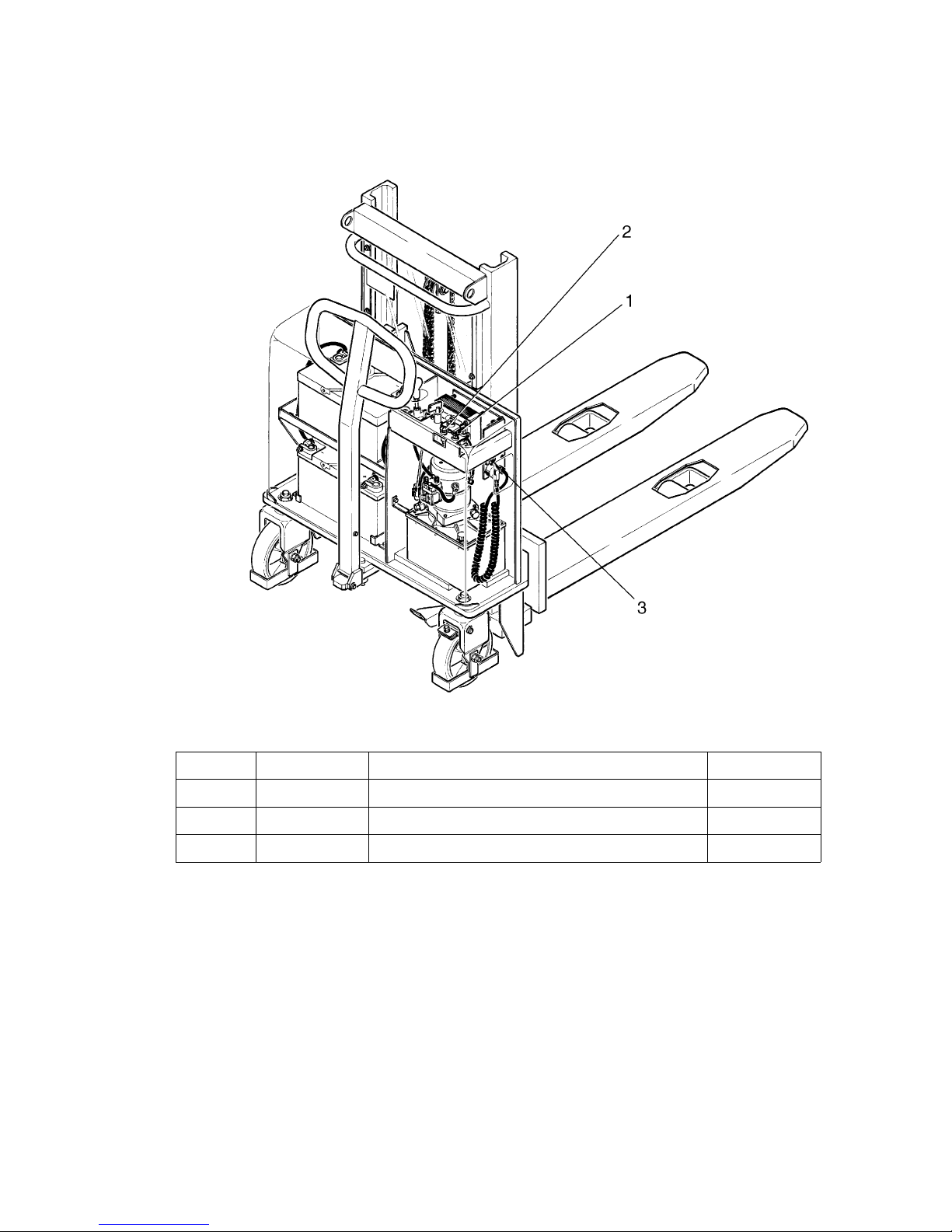
F 7
0708.GB
6.2 Checking the electric fuses
– Prepare the truck for maintenance work (see section 6.1).
– Remove cover.
– Check all fuses for the correct rating and, if necessary, replace.
6.3 Recommissioning the truck
Recommissioning of the truck following the performance of cleaning or maintenance
work is permitted only after the following operations have been performed:
– Check the brake for correct functioning.
Item Designation Type of fuse: HC
1 1F1 Power fuse 100 A
2 F1 Control fuse 8 A
3 F2 Fuse, battery charger 2 A
Page 35

0708.GB
F 8
7 Decommissioning the fork-lift truck
If the fork-lift truck is to be decommissioned for more than 6 months, it must be parked
in a frost-free and dry location and all measures to be taken before, during and following decommissioning must be performed as detailed below.
m
During decommissioning, the fork-lift truck must be jacked up, ensuring that the
wheels are clear of the ground. Only this measure will ensure that wheels and wheel
bearings do not suffer damage.
– Recharge the battery (refer to chapter D).
– Disconnect and clean the battery. Apply pole grease to the battery poles.
A
In addition to this, all instructions given by the battery supplier must be observed.
– Spray all exposed electrical contacts with a suitable contact spray.
7.1 Measures to be taken during decommissioning
Every 6 months:
– Recharge the battery (refer to chapter D).
m
Battery-operated fork lift trucks:
Regular recharging of the battery is very important; otherwise, exhaustive depletion
of the battery caused by self-discharging would occur. Owing to sulfatisation, this will
result in the destruction of the battery.
A
When continiously trickle-charging, it is not necessary to charge the battery every 6
months as a protection against draining.
7.2 Recommissioning the truck
– Thoroughly clean the fork-lift truck.
– Clean the battery. Grease the pole screws using pole grease and reconnect the
battery.
– Recharge the battery (refer to chapter D).
– Check if the hydraulic oil contains condensed water and change if required.
– Start up the fork-lift truck (refer to chapter E).
f
Perform several brake tests immediately after recommissioning the truck.
0708.GB
F 8
7 Decommissioning the fork-lift truck
If the fork-lift truck is to be decommissioned for more than 6 months, it must be parked
in a frost-free and dry location and all measures to be taken before, during and follo-
wing decommissioning must be performed as detailed below.
m
During decommissioning, the fork-lift truck must be jacked up, ensuring that the
wheels are clear of the ground. Only this measure will ensure that wheels and wheel
bearings do not suffer damage.
– Recharge the battery (refer to chapter D).
– Disconnect and clean the battery. Apply pole grease to the battery poles.
A
In addition to this, all instructions given by the battery supplier must be observed.
– Spray all exposed electrical contacts with a suitable contact spray.
7.1 Measures to be taken during decommissioning
Every 6 months:
– Recharge the battery (refer to chapter D).
m
Battery-operated fork lift trucks:
Regular recharging of the battery is very important; otherwise, exhaustive depletion
of the battery caused by self-discharging would occur. Owing to sulfatisation, this will
result in the destruction of the battery.
A
When continiously trickle-charging, it is not necessary to charge the battery every 6
months as a protection against draining.
7.2 Recommissioning the truck
– Thoroughly clean the fork-lift truck.
– Clean the battery. Grease the pole screws using pole grease and reconnect the
battery.
– Recharge the battery (refer to chapter D).
– Check if the hydraulic oil contains condensed water and change if required.
– Start up the fork-lift truck (refer to chapter E).
f
Perform several brake tests immediately after recommissioning the truck.
Page 36

F 9
0708.GB
8 Safety checks to be performed at regular intervals and following any unusual
incidents
A
Carry out a safety check in accordance with national regulations. Junheinrich recommends checks in accordance with FEM Guideline 4.004. Jungheinrich has a special
safety department with trained personnel to carry out such checks.
The truck must be inspected at least annually (refer to national regulations) or after
any unusual event by a qualified inspector. The inspector shall assess the condition
of the truck from purely a safety viewpoint, without regard to operational or economic
circumstances. The inspector shall be sufficiently instructed and experienced to be
able to assess the condition of the truck and the effectiveness of the safety
mechanisms based on the technical regulations and principles governing the
inspection of forklift trucks.
A thorough test of the truck must be undertaken with regard to its technical condition
from a safety aspect. The truck must also be examined for damage caused by
possible improper use. A test report shall be provided. The test results must be kept
for at least the next 2 inspections.
The owner is responsible for ensuring that faults are immediately rectified.
A
A test plate is attached to the truck as proof that it has passed the safety inspection.
This plate indicates the due date for the next inspection.
9 Final de-commissioning, disposal
A
Final, proper decommissioning or disposal of the truck must be performed in accordance with the regulations of the country of application. In particular, regulations governing the disposal of batteries, fuels and electronic and electrical systems must be
observed.
F 9
0708.GB
8 Safety checks to be performed at regular intervals and following any unusual
incidents
A
Carry out a safety check in accordance with national regulations. Junheinrich recom-
mends checks in accordance with FEM Guideline 4.004. Jungheinrich has a special
safety department with trained personnel to carry out such checks.
The truck must be inspected at least annually (refer to national regulations) or after
any unusual event by a qualified inspector. The inspector shall assess the condition
of the truck from purely a safety viewpoint, without regard to operational or economic
circumstances. The inspector shall be sufficiently instructed and experienced to be
able to assess the condition of the truck and the effectiveness of the safety
mechanisms based on the technical regulations and principles governing the
inspection of forklift trucks.
A thorough test of the truck must be undertaken with regard to its technical condition
from a safety aspect. The truck must also be examined for damage caused by
possible improper use. A test report shall be provided. The test results must be kept
for at least the next 2 inspections.
The owner is responsible for ensuring that faults are immediately rectified.
A
A test plate is attached to the truck as proof that it has passed the safety inspection.
This plate indicates the due date for the next inspection.
9 Final de-commissioning, disposal
A
Final, proper decommissioning or disposal of the truck must be performed in accor-
dance with the regulations of the country of application. In particular, regulations go-
verning the disposal of batteries, fuels and electronic and electrical systems must be
observed.
Page 37

0708.GB
F 10
10 Faul localisation and identification
10.1 Fault localisation
A
IIf the fault cannot be eliminated, decommission the truck and inform the service department.
Fault Possible cause Remedial action
Vehicle does
not work.
– Battery is still being
charged
– The key switch is set to
OFF.
– Batteries are insuf-
ficiently charged.
– Fuses defiective
– Battery does not char-
ge.
– Disconnect 230 V connection
– Turn the key clockwise as far as it will
go.
– Check battery charge and charge batte-
ry, if necessary
– Check fuses 1F1 and F1
– Check the charger fuse F2, check the
battery terminal connections.
– Check the magnetic switch (see D2).
Load cannot
be lifted
– Truck is not operational
– Fuse defective
– Hydraulic oil level too
low.
– Carry out all of the remedial actions li-
sted under “Vehicle does not work”.
– Check fuse 1F1.
– Check level of hydraulic oil.
0708.GB
F 10
10 Faul localisation and identification
10.1 Fault localisation
A
IIf the fault cannot be eliminated, decommission the truck and inform the service de-
partment.
Fault Possible cause Remedial action
Vehicle does
not work.
– Battery is still being
charged
– The key switch is set to
OFF.
– Batteries are insuf-
ficiently charged.
– Fuses defiective
– Battery does not char-
ge.
– Disconnect 230 V connection
– Turn the key clockwise as far as it will
go.
– Check battery charge and charge batte-
ry, if necessary
– Check fuses 1F1 and F1
– Check the charger fuse F2, check the
battery terminal connections.
– Check the magnetic switch (see D2).
Load cannot
be lifted
– Truck is not operational
– Fuse defective
– Hydraulic oil level too
low.
– Carry out all of the remedial actions li-
sted under “Vehicle does not work”.
– Check fuse 1F1.
– Check level of hydraulic oil.
 Loading...