

Page 1
ETM/V 320/325 ETV-H 320
06.99-
Operating instructions
50048198
03.06
G
Page 2

1
0903.GB
Important notes on transporting and mounting load lifting devices
to reach trucks
Transport
Depending on the overall height of the lifting mast and the local conditions transport
can be performed in three different ways
– Standing, with the lifting mast mounted (for trucks with low overall height)
– Standing, with martially mounted lifting mast tilted towards the overhead guard (for
trucks with medium overall height). Hydraulic line for the lifting function is interrupted.
– Standing, with the lifting mast dismounted (for trucks with large overall height)
Safety Instructions for Assembly and Commissioning
f
The assembly of the truck on site, commissioning the truck and instructing the driver
must be carried out by personnel trained and authorised by the manufacturer
Connect the hydraulic lines to the basic machine / mast interface and commission the
truck only after having installed the mast as per the instructions.
1
0903.GB
Important notes on transporting and mounting load lifting devices
to reach trucks
Transport
Depending on the overall height of the lifting mast and the local conditions transport
can be performed in three different ways
– Standing, with the lifting mast mounted (for trucks with low overall height)
– Standing, with martially mounted lifting mast tilted towards the overhead guard (for
trucks with medium overall height). Hydraulic line for the lifting function is interrup-
ted.
– Standing, with the lifting mast dismounted (for trucks with large overall height)
Safety Instructions for Assembly and Commissioning
f
The assembly of the truck on site, commissioning the truck and instructing the driver
must be carried out by personnel trained and authorised by the manufacturer
Connect the hydraulic lines to the basic machine / mast interface and commission the
truck only after having installed the mast as per the instructions.
Page 3

0903.GB 20903.GB
2
Page 4

0108.GB
Foreword
The present ORIGINAL OPERATING INSTRUCTIONS are designed to provide
sufficient instruction for the safe operation of the industrial truck. The information is
provided clearly and concisely. The chapters are arranged by letter. Each chapter
starts with page 1. The page identification consists of a chapter letter and a page
number.
For example: Page B 2 is the second page in chapter B.
The operating instructions detail different truck models. When operating and servicing
the truck, make sure that the instructions apply to your truck model.
Safety instructions and important explanations are indicated by the following
graphics:
f
Used before safety instructions which must be observed to avoid danger to
personnel.
m
Used before notices which must be observed to avoid material damage.
A
Used before notices and explanations.
t Used to indicate standard equipment.
o Used to indicate optional equipment.
Our trucks are subject to ongoing development. Jungheinrich reserves the right to
alter the design, equipment and technical features of the truck. No guarantee of
particular features of the truck should therefore be inferred from the present operating
instructions.
Copyright
Copyright of these operating instructions remains with JUNGHEINRICH AG.
Jungheinrich Aktiengesellschaft
Am Stadtrand 35
22047 Hamburg - GERMANY
Telephone: +49 (0) 40/6948-0
www.jungheinrich.com
Page 5

0108.GB
0108.GB
Page 6

I 1
0903.GB
Table of contents
A Correct use and application of the truck
B Description of the truck
1 Application ........................................................................................... B 1
2 Assembly description and functional description ............................... B 2
2.1 Truck ................................................................................................... B 3
2.2 Load lifting system .............................................................................. B 5
3 Technical data - Standard version ...................................................... B 6
3.1 Output data ......................................................................................... B 6
3.2 Dimensions ......................................................................................... B 6
3.3 Standard hoist frame versions ............................................................ B 8
3.4 EN standards ...................................................................................... B 9
3.5 Operation conditions ........................................................................... B 9
4 Location of instruction labels and identification plates ....................... B 10
4.1 Truck identification plate ..................................................................... B 11
4.2 Load diagram / capacity / load centre / lifting height ........................... B 11
4.3 Load diagram, capacity / load centre / fork ......................................... B 12
4.4 Load diagram, capacity / lateral traversing device .............................. B 12
4.5 Pick-up points for lifting jack ................................................................ B 12
4.6 Information sign: Observe the operating instructions! ......................... B 12
C Transportation and commissioning
1 Loading and unloading of trucks by crane .......................................... C 1
2 Commissioning .................................................................................... C 2
3 Parking brake transport restraint ......................................................... C 2
D Battery - servicing, recharging, replacement
1 Safety regulations governing the handling of lead-acid batteries ........ D 1
2 Battery type ......................................................................................... D 2
3 Exposing the battery ........................................................................... D 2
3.1 Bypassing the drive current interruption .............................................. D 3
3.2 Battery trolley emergency unlocking system ....................................... D 3
4 Charging the battery ............................................................................ D 4
5 Removing and installing the battery .................................................... D 5
6 Battery discharge indicator, battery discharge monitor
and hour meter .................................................................................... D 6
Page 7

0903.GB
I 2
E Operation
1 Safety regulations governing the operation of the truck ...................... E 1
2 Description of the operating controls and indicators ........................... E 2
3 Start-up of truck ................................................................................... E 6
3.1 How to use the safety belt o .............................................................. E 7
3.2 Emergency stop device ....................................................................... E 9
4 Truck operation ................................................................................... E 10
4.1 Safety regulations applicable when operating the truck ...................... E 10
4.2 Driving, steering, braking .................................................................... E 11
4.3 Adjusting the fork tines ........................................................................ E 13
4.4 Picking up and setting down loads ...................................................... E 13
4.5 Picking up, lifting and transporting of loads ......................................... E 16
4.6 Operating an attachment ..................................................................... E 17
4.7 Rendering vehicle safe when parking ................................................. E 17
5 Information and service display (LISA) ............................................... E 18
5.1 LED warning lamps ............................................................................. E 19
5.2 Key assignment ................................................................................... E 19
5.3 Displays ............................................................................................... E 20
5.4 Changing truck parameters ................................................................. E 21
6 Fault locating operations ..................................................................... E 22
7 Mechanical stand-by steering system (emergency steering operation) E 23
8 Auxiliary electrical system ................................................................... E 25
8.1 Seat heating ........................................................................................ E 25
8.2 Floodlight ............................................................................................ E 25
8.3 360° warning light ............................................................................... E 26
8.4 Flash lamp ........................................................................................... E 26
8.5 Override button (ESA / Electrical lifting limitation) ............................... E 27
9 Single-lever operation o ..................................................................... E 28
9.1 Driving, steering, braking .................................................................... E 28
9.2 Picking up and setting down loads ...................................................... E 30
9.3 Picking up, lifting and transporting of loads ......................................... E 32
9.4 Operating an attachment ..................................................................... E 33
Page 8

I 3
0903.GB
F Maintenance of the fork-lift truck
1 Operational safety and environmental protection .................................F 1
2 Safety regulations applicable to truck maintenance .............................F 1
3 Servicing and inspection ......................................................................F 3
4 Maintenance Check - list ETM/V 320-325 ...........................................F 4
5 Lubrication Schedule ETMV 320-325 ..................................................F 6
5.1 Fuels, coolants and lubricants ..............................................................F 7
5.2 Reservoir filling level ETM/V 320/325 ..................................................F 7
6 Instructions for the servicing operations ...............................................F 8
6.1 Preparing the truck for the performance of servicing
and maintenance operations ................................................................F 8
6.2 Safety belt maintenance o ..................................................................F 8
6.3 Opening the arm rest ...........................................................................F 9
6.4 Opening the hood .................................................................................F 9
6.5 Opening the battery doors and the seat hood ......................................F 10
6.6 Checking the hydraulic oil level ............................................................F 10
6.7 Pressure filter for regenerative lowering ..............................................F 11
6.8 Checking the electric fuses ..................................................................F 12
6.9 Recommissioning the truck ..................................................................F 13
7 Decommissioning the truck ..................................................................F 13
7.1 Operations to be performed prior to decommissioning ........................F 13
7.2 Measures to be taken during decommissioning ...................................F 13
7.3 Recommissioning the truck ..................................................................F 14
8 Safety checks to be performed at regular intervals and following
any untoward incidents (D: Accident prevention check
according to BGV D27) ........................................................................F 14
Page 9

0903.GB
I 4
0903.GB
I 4
Page 10

A 1
0600.GB
A Correct use and application of the truck
A
The “Guidelines for the Correct Use and Application of Industrial Trucks” (VDMA) are
included in the scope of delivery for this truck. The guidelines are part of these operating instructions and must always be heeded. National regulations are fully applicable.
The fork lift truck described in these operating instructions is a truck that is suitable
for lifting and transporting loads.
It must be used, operated and maintained according to the information in these operating instructions. Any other uses are outside the design envelope and can lead to
injury to persons or damage to equipment and property. Above all, overloading
caused by excessively heavy or unbalanced loads must be avoided. The max. admissible load to be picked up is indicated on the identification plate or load diagram label
shown on the truck. The fork lift truck must not be operated in spaces subject to fire
or explosion hazards, or in spaces where corrosive or very dusty atmospheres prevail.
Duties of the user: A “user” within the meaning of these operating instructions is defined as any natural or legal person who either uses the fork lift truck himself, or on
whose behalf it is used. In special cases (e.g. leasing or renting), the user is considered the person, who, in accordance with existing contractual agreements between the
owner and the user of the fork lift truck, is charged with the observance of the operating duties.
The user must ensure that the truck is not abused and only used within its design limits and that all danger to life and limb of the operator, or third parties, is avoided. In
addition to this, it must be ensured that the relevant accident prevention regulations
and other safety-related provisions, as well as the operating, servicing and maintenance guidelines, are observed. The user must also ensure that all persons operating
the truck have read and understood these operating instructions.
m
If these operating instructions are not observed the warranty becomes void. The
same applies if improper works are carried out at the device by the customer and/or
third parties without permission of our Customer Service.
Mounting of attachments: The mounting or installation of any attachments which
will interfere with, or supplement, the functions of the truck is permitted only after written approval by the manufacturer has been obtained. If necessary, the approval of
local authorities has to be obtained.
Any approval obtained from local authorities does not, however, make the approval
by the manufacturer unnecessary.
A 1
0600.GB
A Correct use and application of the truck
A
The “Guidelines for the Correct Use and Application of Industrial Trucks” (VDMA) are
included in the scope of delivery for this truck. The guidelines are part of these ope-
rating instructions and must always be heeded. National regulations are fully applica-
ble.
The fork lift truck described in these operating instructions is a truck that is suitable
for lifting and transporting loads.
It must be used, operated and maintained according to the information in these ope-
rating instructions. Any other uses are outside the design envelope and can lead to
injury to persons or damage to equipment and property. Above all, overloading
caused by excessively heavy or unbalanced loads must be avoided. The max. admis-
sible load to be picked up is indicated on the identification plate or load diagram label
shown on the truck. The fork lift truck must not be operated in spaces subject to fire
or explosion hazards, or in spaces where corrosive or very dusty atmospheres pre-
vail.
Duties of the user: A “user” within the meaning of these operating instructions is de-
fined as any natural or legal person who either uses the fork lift truck himself, or on
whose behalf it is used. In special cases (e.g. leasing or renting), the user is conside-
red the person, who, in accordance with existing contractual agreements between the
owner and the user of the fork lift truck, is charged with the observance of the opera-
ting duties.
The user must ensure that the truck is not abused and only used within its design li-
mits and that all danger to life and limb of the operator, or third parties, is avoided. In
addition to this, it must be ensured that the relevant accident prevention regulations
and other safety-related provisions, as well as the operating, servicing and mainte-
nance guidelines, are observed. The user must also ensure that all persons operating
the truck have read and understood these operating instructions.
m
If these operating instructions are not observed the warranty becomes void. The
same applies if improper works are carried out at the device by the customer and/or
third parties without permission of our Customer Service.
Mounting of attachments: The mounting or installation of any attachments which
will interfere with, or supplement, the functions of the truck is permitted only after writ-
ten approval by the manufacturer has been obtained. If necessary, the approval of
local authorities has to be obtained.
Any approval obtained from local authorities does not, however, make the approval
by the manufacturer unnecessary.
Page 11

0600.GB
A 2
0600.GB
A 2
Page 12
B 1
0903.GB
B Description of the truck
1 Application
The ETM/V 320-325 is an electrically driven three-wheel truck incorporating a traversing mast and a lateral seat. It is intended for the lifting and transportation of goods
on level ground. It can pick up pallets of open ground support, pallets provided with
lateral boards arranged outside or inside the range of the load-bearing wheels, or trolleys. Loads can be stacked in and out and transported across greater distances.
Its capacity is shown on the identification label.
Type Capacity Load centre distance
ETM/V 320 1400 kg 600 mm
ETM/V 325 1600 kg 600 mm
B 1
0903.GB
B Description of the truck
1 Application
The ETM/V 320-325 is an electrically driven three-wheel truck incorporating a traver-
sing mast and a lateral seat. It is intended for the lifting and transportation of goods
on level ground. It can pick up pallets of open ground support, pallets provided with
lateral boards arranged outside or inside the range of the load-bearing wheels, or trol-
leys. Loads can be stacked in and out and transported across greater distances.
Its capacity is shown on the identification label.
Type Capacity Load centre distance
ETM/V 320 1400 kg 600 mm
ETM/V 325 1600 kg 600 mm
Page 13
0903.GB
B 2
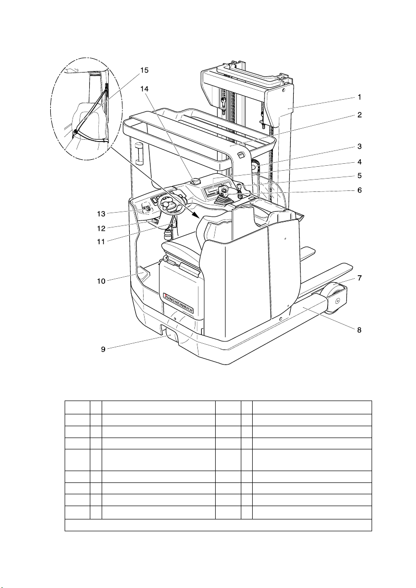
2 Assembly description and functional description
Item Designation Item Designation
1 t Clear-view lifting mast 9 t Drive wheel
2 t Overhead guard 10 t Foot switch
3 t Free-lift cylinder 11 t Battery trolley unlocking system
4 t Information and
service display (LISA)
12 t Parking brake
5 o Auxiliary hydraulics (ZH2) 13 t Key switch
6 t Multi-pilot stick 14 t Master switch (emergency stop)
7 t Load-bearing wheels 15 o Safety belt
8 t Wheel arm
t = Standard equipment o = Optional equipment
0903.GB
B 2
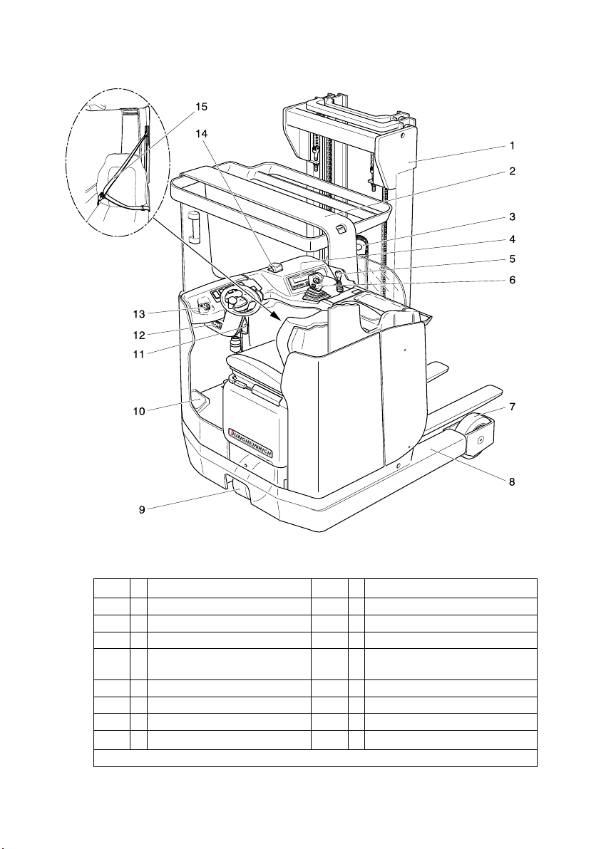
2 Assembly description and functional description
Item Designation Item Designation
1 t Clear-view lifting mast 9 t Drive wheel
2 t Overhead guard 10 t Foot switch
3 t Free-lift cylinder 11 t Battery trolley unlocking system
4 t Information and
service display (LISA)
12 t Parking brake
5 o Auxiliary hydraulics (ZH2) 13 t Key switch
6 t Multi-pilot stick 14 t Master switch (emergency stop)
7 t Load-bearing wheels 15 o Safety belt
8 t Wheel arm
t = Standard equipment o = Optional equipment
Page 14

B 3
0903.GB
2.1 Truck
Safety installations: The enclosed truck contour featuring rounded edges ensures
safe handling of the ETM/V 320-325 truck. The driver is protected by the overhead
guard (2). The drive wheel (9) and the load-bearing wheels (7) are enclosed by a sturdy collision guard.
The master switch (14) ensures instant cut-out of all electrical functions in an emergency. Six red LED warning lights in the information and service display (4) indicate
the following states:
– Direction of motion Forward(V), „Drive direction“
– Parking brake applied
– Direction of motion Backward (R), „Load direction“
– Lack of brake liquid
– Center position of lateral traversing device (option)
– Battery locking
In case of malfunctions within the hydraulic system, line break safety devices limit the
speed at which the load is lowered.
Indicating instruments: Information and service display (LISA) (4) with large indications in LCD-technology. Hour meter and battery discharge indicator with lifting movement cut-out function.
Drive system: The complete drive unit is screwed into the vehicle chassis. A 6 kW
rotary current generator runs the driving wheel (9) via a front bevel-wheel gear mechanism.
The electronic drive current control system provides variable speed to the drive motor, thus allowing smooth starting without jerks, vigorous accelerating and electronically controlled regenerative braking.
The rate of energy regeneration can be set with the LISA system.
Brake system: Two independent brake systems act on the drive wheel. The service
brake is designed as a hydraulic drum brake with asbestos-free brake linings and is
applied by means of the foot pedal. The parking brake (12) acts mechanically as an
electromagnetic brake on the drum brake by pulling a rope.
The brake fluid level is monitored by the LISA system. A warning light shows when
the parking brake is applied.
Malfunctions in the steering system and in the parking brake system (release of emergency stop) are indicated in the LISA diplay.
Steering system: Chain-operated steering using a steering gear and, as standard,
electric steering. The pivoted drive unit can be swivelled by 90° to both sides.
Driver position: The driver’s place is ergonomically designed and equipped with a
large foot space. In order to obtain an ergonomic seating position, the driver can adjust the driver’s seat and the steering column horizontally and vertically.
Accelerator and brake pedals are arranged as found in normal vehicles.
B 3
0903.GB
2.1 Truck
Safety installations: The enclosed truck contour featuring rounded edges ensures
safe handling of the ETM/V 320-325 truck. The driver is protected by the overhead
guard (2). The drive wheel (9) and the load-bearing wheels (7) are enclosed by a stur-
dy collision guard.
The master switch (14) ensures instant cut-out of all electrical functions in an emer-
gency. Six red LED warning lights in the information and service display (4) indicate
the following states:
– Direction of motion Forward(V), „Drive direction“
– Parking brake applied
– Direction of motion Backward (R), „Load direction“
– Lack of brake liquid
– Center position of lateral traversing device (option)
– Battery locking
In case of malfunctions within the hydraulic system, line break safety devices limit the
speed at which the load is lowered.
Indicating instruments: Information and service display (LISA) (4) with large indica-
tions in LCD-technology. Hour meter and battery discharge indicator with lifting mo-
vement cut-out function.
Drive system: The complete drive unit is screwed into the vehicle chassis. A 6 kW
rotary current generator runs the driving wheel (9) via a front bevel-wheel gear me-
chanism.
The electronic drive current control system provides variable speed to the drive mo-
tor, thus allowing smooth starting without jerks, vigorous accelerating and electroni-
cally controlled regenerative braking.
The rate of energy regeneration can be set with the LISA system.
Brake system: Two independent brake systems act on the drive wheel. The service
brake is designed as a hydraulic drum brake with asbestos-free brake linings and is
applied by means of the foot pedal. The parking brake (12) acts mechanically as an
electromagnetic brake on the drum brake by pulling a rope.
The brake fluid level is monitored by the LISA system. A warning light shows when
the parking brake is applied.
Malfunctions in the steering system and in the parking brake system (release of emer-
gency stop) are indicated in the LISA diplay.
Steering system: Chain-operated steering using a steering gear and, as standard,
electric steering. The pivoted drive unit can be swivelled by 90° to both sides.
Driver position: The driver’s place is ergonomically designed and equipped with a
large foot space. In order to obtain an ergonomic seating position, the driver can ad-
just the driver’s seat and the steering column horizontally and vertically.
Accelerator and brake pedals are arranged as found in normal vehicles.
Page 15
0903.GB
B 4
Item Designation Item Designation
1 t Clear-view lifting mast 9 t Drive wheel
2 t Overhead guard 10 t Foot switch
3 t Free-lift cylinder 11 t Battery trolley unlocking system
4 t Information and
service display (LISA)
12 t Parking brake
5 o Auxiliary hydraulics (ZH2) 13 t Key switch
6 t Multi-pilot stick 14 t Master switch (emergency stop)
7 t Load-bearing wheels 15 o Safety beltt
8 t Wheel arm
t = Standard equipment o = Optional equipment
Page 16

B 5
0903.GB
Operating controls and indicators: The operating controls and indicators are clearly laid out and arranged at the driver position.
The logically structured multi-pilot stick (6) allows single-handed operation of the
drive direction, lifting/ lowering, forward/backward traversing of mast, mast inclination, traversing to the left/right (in lateral traversing operation - auxiliary hydraulics
ZH1) and horn functions.
The information and service display (LISA) (4) combines a battery discharge indicator
and a working hour meter. The battery discharge indicator is designed as a discharge
monitor and will interrupt the lifting function when the battery is depleted to prevent
battery exhaustion.
As an option, an auxiliary hydraulic system ZH2 can be operated via the control lever
(5).
Hydraulic system: Pump unit with a remotely ventilated series-wound motor and a
noiseless precision jetting pump integrated in the oil reservoir. The system is controlled via the multi-pilot stick (6) and the optional auxiliary hydraulics (5).
Instead of the multi-pilot, an optional control via individual levers is possible
(see chapter E).
Electric system: 48 V two-wire system.
As a standard feature, the truck is equipped with an electronic drive and lifting control
system. The electronic drive control system variably controls the travelling speed and
allows counter-current braking when switching the direction of travel.
The information and service display (LISA) (4) allows a adjustment of the driving and
lifting parameters according to the current requirements. Warning indications, operating error indications and service functions are also shown on the LISA.
(For possible drive batteries, see chapter D.)
2.2 Load lifting system
Mast holder: The mast holder is borne by supporting rollers. The protracting and re-
tracting movements are carried out directly by a simply telescoping traversing cylinder. The guide rails for the mast holder are screwed onto the wheel arms (8).
Hoist frame: The trucks are equipped with tiltable, telescoping free-vision hoist frames (1) supported by the mast holder. Adjustable lateral rollers and guide pieces absorb the lateral pressure acting on the fork carrier when transporting unbalanced
loads. The mounting of the fork to the fork carrier permits adjustments to be made to
the tines. In the case of the double-lift triplex mast (DZ), the initial lifting sequence of
the load carriage (free lift), which does not change the total height, is effected by a
short free-lift cylinder (3) arranged off-centre. In the case of the telescopic mast (ZT),
the free-lift sequence is limited to 80 mm due to the construction of the truck.
Attachments: Mechanical and hydraulic attachments are available as optional
equipment.
B 5
0903.GB
Operating controls and indicators: The operating controls and indicators are clear-
ly laid out and arranged at the driver position.
The logically structured multi-pilot stick (6) allows single-handed operation of the
drive direction, lifting/ lowering, forward/backward traversing of mast, mast inclinati-
on, traversing to the left/right (in lateral traversing operation - auxiliary hydraulics
ZH1) and horn functions.
The information and service display (LISA) (4) combines a battery discharge indicator
and a working hour meter. The battery discharge indicator is designed as a discharge
monitor and will interrupt the lifting function when the battery is depleted to prevent
battery exhaustion.
As an option, an auxiliary hydraulic system ZH2 can be operated via the control lever
(5).
Hydraulic system: Pump unit with a remotely ventilated series-wound motor and a
noiseless precision jetting pump integrated in the oil reservoir. The system is control-
led via the multi-pilot stick (6) and the optional auxiliary hydraulics (5).
Instead of the multi-pilot, an optional control via individual levers is possible
(see chapter E).
Electric system: 48 V two-wire system.
As a standard feature, the truck is equipped with an electronic drive and lifting control
system. The electronic drive control system variably controls the travelling speed and
allows counter-current braking when switching the direction of travel.
The information and service display (LISA) (4) allows a adjustment of the driving and
lifting parameters according to the current requirements. Warning indications, opera-
ting error indications and service functions are also shown on the LISA.
(For possible drive batteries, see chapter D.)
2.2 Load lifting system
Mast holder: The mast holder is borne by supporting rollers. The protracting and re-
tracting movements are carried out directly by a simply telescoping traversing cylin-
der. The guide rails for the mast holder are screwed onto the wheel arms (8).
Hoist frame: The trucks are equipped with tiltable, telescoping free-vision hoist fra-
mes (1) supported by the mast holder. Adjustable lateral rollers and guide pieces ab-
sorb the lateral pressure acting on the fork carrier when transporting unbalanced
loads. The mounting of the fork to the fork carrier permits adjustments to be made to
the tines. In the case of the double-lift triplex mast (DZ), the initial lifting sequence of
the load carriage (free lift), which does not change the total height, is effected by a
short free-lift cylinder (3) arranged off-centre. In the case of the telescopic mast (ZT),
the free-lift sequence is limited to 80 mm due to the construction of the truck.
Attachments: Mechanical and hydraulic attachments are available as optional
equipment.
Page 17

0903.GB
B 6
3 Technical data - Standard version
A
Technical data to VDI 2198.
Technical data are subject to alteration and extension in scope.
3.1 Output data
d)h3 ≥ 6201 - 8000 mm = 0,10 m/s
h3 ≥ 8001 mm = 0,08 m/s
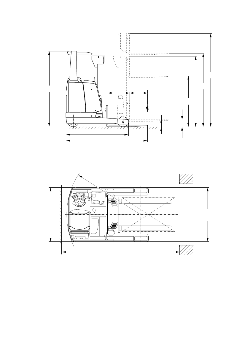
3.2 Dimensions
a) Length of fork: 800 mm; 560 Ah battery: +90 mm; 700 Ah battery: +162 mm
b) 560 Ah battery: -90 mm; 700 Ah battery: +162 mm
c) ± 5 mm; 560 Ah battery: +90 mm; 700 Ah battery: +162 mm
d) 700 Ah battery: a( +162 mm, b) -162 mm, c) +162 mm
e)Overall height h
1
≤2500: 2075 mm
Overall height h
1
≥2200: 2400 mm, 420/560 Ah battery: 2075mm
700 Ah battery: 2190 mm
Overall height h
1
>2400 mm = 2190 mm
Designation ETM/V 320 ETM/V 325
Q Capacity (at C = 600 mm) 2000 2500 Kg
C Load centre distance 600 600 mm
Travelling speed
with / without load
11,7 11,7 Km/h
Lifting speed
with / without load
0,28 / 0,43 0,23 / 0,37 m/s
(±10%)
Lowering speed
with / without load
0,50 / 0,50 0,50 / 0,50 m/s
(±15%)
Traversing speed
with / without load d)
0,12 0,12 m/s
Climbing ability
with / without load
7 / 11 6 / 11 %
Max. climbing ability (max. 5 min)
with / without load
10 / 15 10 / 15 %
Designation ETM/V 320
(ZT/DZ)
ETM/V325
(ZT/DZ)
s Height of lowered fork 50 50 mm
h
6
Height above overhead guard e) 2075/2190 2075/2190 mm
l
1
Total length a) 2034/2060 2124/2150 mm
l
4
Traversing distance b) 690/664 755/729 mm
l
7
Length across wheel arms 1903 2058 mm
b
1
Total width 1126/1244 1216/1334 mm
b
2
Total width 1106/1186 1106/1186 mm
W
a
Turning radius 1745/1753 1897/1905 mm
Ast
Working aisle width
800 x 1200 pallets, lengthwise c)
2669/2695 2756/2782 mm
Ast
Working aisle width
1000 x 1200 pallets, crosswise c)
2469/2495 2556/2582 mm
Dead weight: Refer to truck identification plate
0903.GB
B 6
3 Technical data - Standard version
A
Technical data to VDI 2198.
Technical data are subject to alteration and extension in scope.
3.1 Output data
d)h3 ≥ 6201 - 8000 mm = 0,10 m/s
h3 ≥ 8001 mm = 0,08 m/s
3.2 Dimensions
a) Length of fork: 800 mm; 560 Ah battery: +90 mm; 700 Ah battery: +162 mm
b) 560 Ah battery: -90 mm; 700 Ah battery: +162 mm
c) ± 5 mm; 560 Ah battery: +90 mm; 700 Ah battery: +162 mm
d) 700 Ah battery: a( +162 mm, b) -162 mm, c) +162 mm
e)Overall height h
1
≤2500: 2075 mm
Overall height h
1
≥2200: 2400 mm, 420/560 Ah battery: 2075mm
700 Ah battery: 2190 mm
Overall height h
1
>2400 mm = 2190 mm
Designation ETM/V 320 ETM/V 325
Q Capacity (at C = 600 mm) 2000 2500 Kg
C Load centre distance 600 600 mm
Travelling speed
with / without load
11,7 11,7 Km/h
Lifting speed
with / without load
0,28 / 0,43 0,23 / 0,37 m/s
(±10%)
Lowering speed
with / without load
0,50 / 0,50 0,50 / 0,50 m/s
(±15%)
Traversing speed
with / without load d)
0,12 0,12 m/s
Climbing ability
with / without load
7 / 11 6 / 11 %
Max. climbing ability (max. 5 min)
with / without load
10 / 15 10 / 15 %
Designation ETM/V 320
(ZT/DZ)
ETM/V325
(ZT/DZ)
s Height of lowered fork 50 50 mm
h
6
Height above overhead guard e) 2075/2190 2075/2190 mm
l
1
Total length a) 2034/2060 2124/2150 mm
l
4
Traversing distance b) 690/664 755/729 mm
l
7
Length across wheel arms 1903 2058 mm
b
1
Total width 1126/1244 1216/1334 mm
b
2
Total width 1106/1186 1106/1186 mm
W
a
Turning radius 1745/1753 1897/1905 mm
Ast
Working aisle width
800 x 1200 pallets, lengthwise c)
2669/2695 2756/2782 mm
Ast
Working aisle width
1000 x 1200 pallets, crosswise c)
2469/2495 2556/2582 mm
Dead weight: Refer to truck identification plate
Page 18
B 7
0903.GB
.
h
2
s
h
2
l
4
l
7
l
1
h
1
h
6
h
3
h
4
Q
c
Ast
b
1
b
2
Wa
B 7
0903.GB
.
h
2
s
h
2
l
4
l
7
l
1
h
1
h
6
h
3
h
4
Q
c
Ast
b
1
b
2
Wa
Page 19
0903.GB
B 8
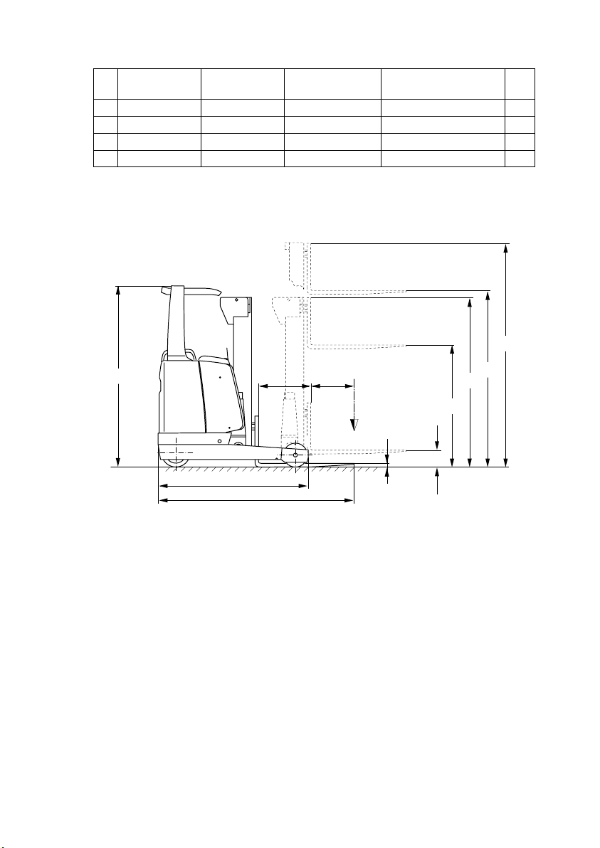
3.3 Standard hoist frame versions
* ETM/V 320 / ETM/V 325
** ETV-H 320 / ETV 320
Designation Telescopic
mast (ZT)*
Double lift
triplex mast (DZ)*
Double lift triplex mast
(DZ), reinforced **
h
1
Total height 2050 - 2700 2050 - 3440 3100 - 4470 mm
h
2
Free lift 100 1320 - 2710 2370 - 3740 mm
h
3
Lift 2900 - 4200 4250 - 8420 7400 - 11510 mm
h
4
Max. height 3591 - 4891 4996 - 9166 8146 - 12256 mm
h
2
s
h
2
l
4
l
7
l
1
h
1
h
6
h
3
h
4
Q
c
0903.GB
B 8
3.3 Standard hoist frame versions
* ETM/V 320 / ETM/V 325
** ETV-H 320 / ETV 320
Designation Telescopic
mast (ZT)*
Double lift
triplex mast (DZ)*
Double lift triplex mast
(DZ), reinforced **
h
1
Total height 2050 - 2700 2050 - 3440 3100 - 4470 mm
h
2
Free lift 100 1320 - 2710 2370 - 3740 mm
h
3
Lift 2900 - 4200 4250 - 8420 7400 - 11510 mm
h
4
Max. height 3591 - 4891 4996 - 9166 8146 - 12256 mm
h
2
s
h
2
l
4
l
7
l
1
h
1
h
6
h
3
h
4
Q
c
Page 20

B 9
0903.GB
3.4 EN standards
Continuous sound level:
70 dB(A)
according to EN 12053 as stipulated in ISO 4871.
A
The continues sound level is an average value determined according to the standard’s guidelines and takes into consideration the sound level when driving, lifting
and in idle mode. The sound level is measured at the driver’s ear.
Vibration: 0.40 m/s
2
according to document N47E of CEN/TC 150/WG8.
A
The vibration acceleration applied to the operator’s body is measured according the
standard’s guidelines as a linearly integrated, weighted acceleration in vertical direction. The acceleration is measured when driving across bumps at steady speed.
Electromagnetic compatibility (EMC)
The following limit values are observed according to the
product standards “Electromagnetic Compatibility of Industrial Trucks (9/95)“:
- interference emission (EN 50081-1)
- interference immunity (EN 50082-2)
- electrostatic discharge (EN 61000-4-2).
A
Electrical or electronic components and their arrangement may only be modified after
written approval by the manufacturer has been obtained.
3.5 Operation conditions
Environmental temperature
– in operation –25°C to 40°C
A
If the truck is operated continuously below 0°C, it is recommended to fill the hydraulic
system with frost resisting oil as approved by the manufacturer.
For applications in cold stores resp. in areas with extreme temperature or humidity
changes the truck has to be specially equipped and approved.
B 9
0903.GB
3.4 EN standards
Continuous sound level:
70 dB(A)
according to EN 12053 as stipulated in ISO 4871.
A
The continues sound level is an average value determined according to the stan-
dard’s guidelines and takes into consideration the sound level when driving, lifting
and in idle mode. The sound level is measured at the driver’s ear.
Vibration: 0.40 m/s
2
according to document N47E of CEN/TC 150/WG8.
A
The vibration acceleration applied to the operator’s body is measured according the
standard’s guidelines as a linearly integrated, weighted acceleration in vertical direc-
tion. The acceleration is measured when driving across bumps at steady speed.
Electromagnetic compatibility (EMC)
The following limit values are observed according to the
product standards “Electromagnetic Compatibility of In-
dustrial Trucks (9/95)“:
- interference emission (EN 50081-1)
- interference immunity (EN 50082-2)
- electrostatic discharge (EN 61000-4-2).
A
Electrical or electronic components and their arrangement may only be modified after
written approval by the manufacturer has been obtained.
3.5 Operation conditions
Environmental temperature
– in operation –25°C to 40°C
A
If the truck is operated continuously below 0°C, it is recommended to fill the hydraulic
system with frost resisting oil as approved by the manufacturer.
For applications in cold stores resp. in areas with extreme temperature or humidity
changes the truck has to be specially equipped and approved.
Page 21
0903.GB
B 10
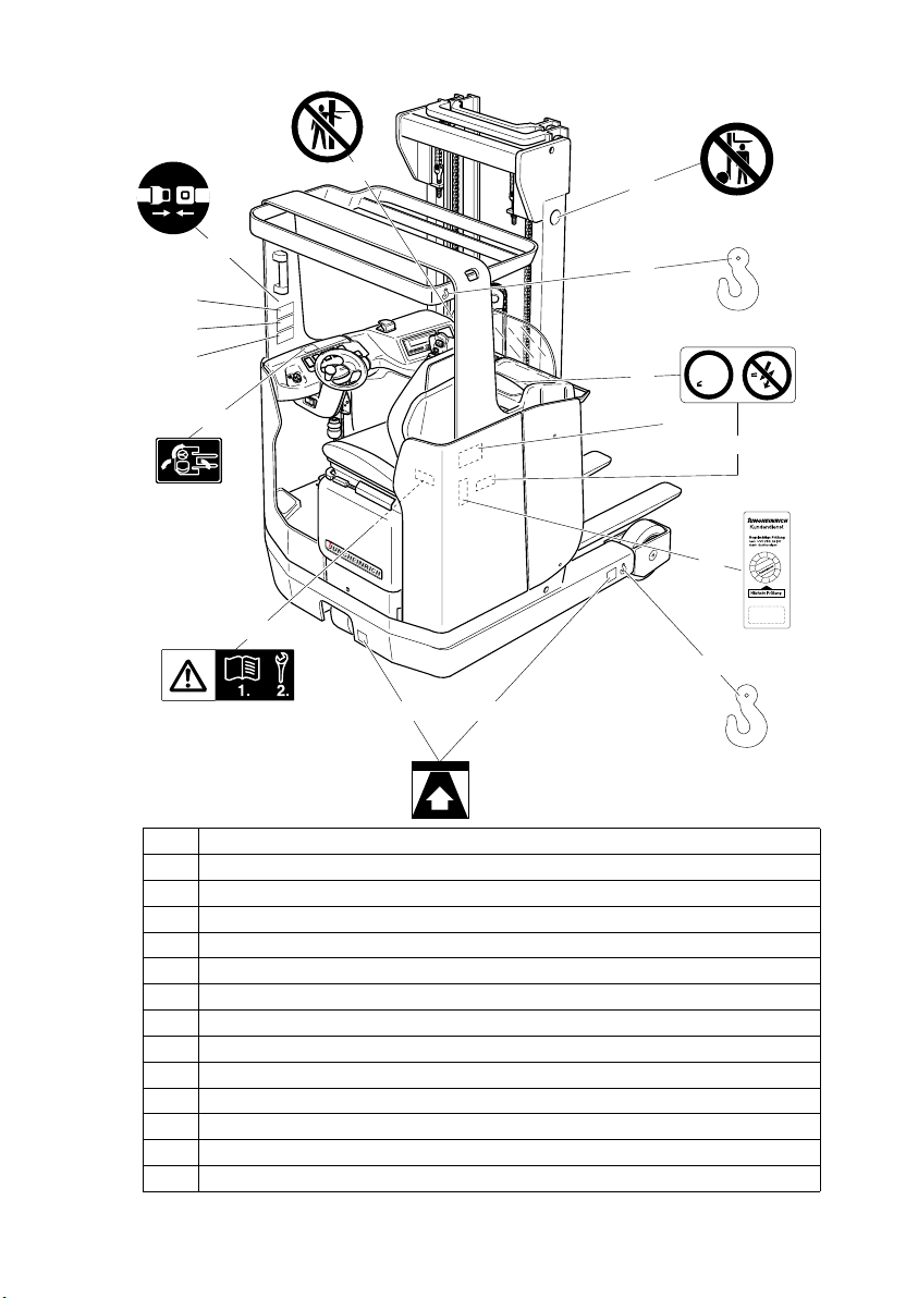
4 Location of instruction labels and identification plates
Item Designation
16 Prohibitive sign “Keep away from under the load lifting device”
17 Pick-up points for crane transportation
18 Warning sign "Low voltage electronics"
19 Truck identification plate
20 Plaque confirming accident prevention checks (only D)
21 Pick-up points for lifting jack
22 Attention: Observe the operating instructions
23 Drive direction when locking the steering wheel
24 Load diagram, capacity / lateral traversing device
25 Load diagram, capacity / load centre / fork
26 Load diagram, capacity / load centre / lifting height
26.1 Sign: Put on safety belt
27 Prohibitive sign “Do not reach through the hoist frame”
19
26
24
25
16
17
18
23
21
17
mV
1,5 V
21
22
20
18
27
1
2
1
1
1
0
9
8
7
6
5
4
3
2
1
1
9
9
6
Ihr Kundendienst-Partner
26.1
0903.GB
B 10
4 Location of instruction labels and identification plates
Item Designation
16 Prohibitive sign “Keep away from under the load lifting device”
17 Pick-up points for crane transportation
18 Warning sign "Low voltage electronics"
19 Truck identification plate
20 Plaque confirming accident prevention checks (only D)
21 Pick-up points for lifting jack
22 Attention: Observe the operating instructions
23 Drive direction when locking the steering wheel
24 Load diagram, capacity / lateral traversing device
25 Load diagram, capacity / load centre / fork
26 Load diagram, capacity / load centre / lifting height
26.1 Sign: Put on safety belt
27 Prohibitive sign “Do not reach through the hoist frame”
19
26
24
25
16
17
18
23
21
17
mV
1,5 V
21
22
20
18
27
1
2
1
1
1
0
9
8
7
6
5
4
3
2
1
1
9
9
6
Ihr Kundendienst-Partner
26.1
Page 22
B 11
0903.GB
4.1 Truck identification plate
A
In event of queries relating to the truck or spare part orders, please state the serial
no. (29) of the truck.
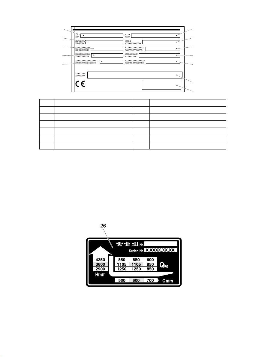
4.2 Load diagram / capacity / load centre / lifting height
The load diagram (26) shows the capacity of the truck in Q kg with the hoist frame in
vertical position. The diagram indicates the maximum capacity at a standard load
centre* C (in mm) and at the desired lifting height H (in mm) in the form of a table.
*) Apart from the height of the load, the standard load centre also includes the width
of the load.
Example showing the determination of the max. capacity:
At a load centre C of 600 mm and a max. lifting height H of 3600 mm, the max. capacity Qkg is 1105 kg.
Item Designation Item Designation
28 Type 34 Manufacturer
29 Serial No. 35 Min./max. battery weight in kg
30 Rated capacity in kg 36 Drive power in kW
31 Battery: Voltage V 37 Load centre distance in mm
32 Empty weight without battery in kg 38 Year of manufacture
33 Manufacturer logo 39 Option
34
33
3532
3631
3730
3829
3928
B 11
0903.GB
4.1 Truck identification plate
A
In event of queries relating to the truck or spare part orders, please state the serial
no. (29) of the truck.
4.2 Load diagram / capacity / load centre / lifting height
The load diagram (26) shows the capacity of the truck in Q kg with the hoist frame in
vertical position. The diagram indicates the maximum capacity at a standard load
centre* C (in mm) and at the desired lifting height H (in mm) in the form of a table.
*) Apart from the height of the load, the standard load centre also includes the width
of the load.
Example showing the determination of the max. capacity:
At a load centre C of 600 mm and a max. lifting height H of 3600 mm, the max. capa-
city Qkg is 1105 kg.
Item Designation Item Designation
28 Type 34 Manufacturer
29 Serial No. 35 Min./max. battery weight in kg
30 Rated capacity in kg 36 Drive power in kW
31 Battery: Voltage V 37 Load centre distance in mm
32 Empty weight without battery in kg 38 Year of manufacture
33 Manufacturer logo 39 Option
34
33
3532
3631
3730
3829
3928
Page 23
0903.GB
B 12
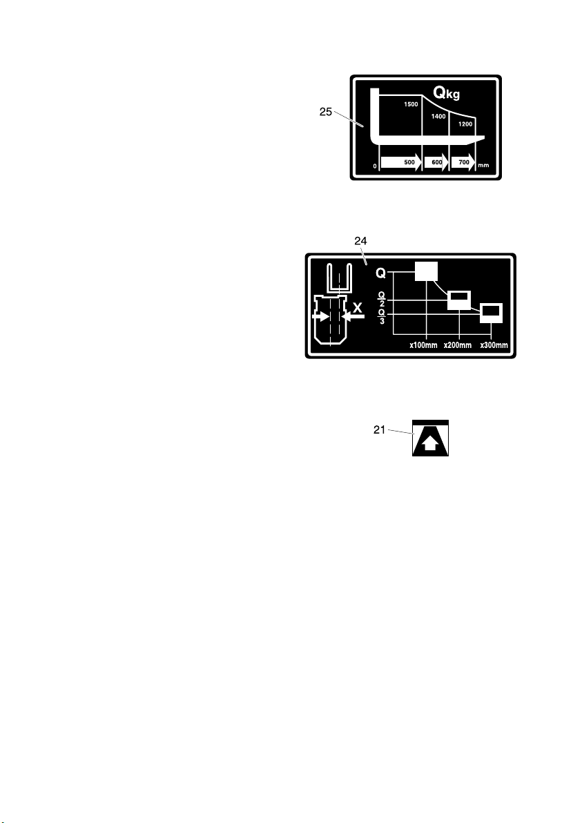
4.3 Load diagram, capacity / load centre / fork
The load diagram (25) shows the capacity Q of the fork in kg. A diagram shows
the max. capacity at different load
centres (C in mm).
4.4 Load diagram, capacity / lateral traversing device
The load diagram (24) shows the reduced capacity Q in kg with the lateral traversing device extended.
4.5 Pick-up points for lifting jack
For lifting and jacking up the truck.
(see chapter F)
4.6 Information sign: Observe the operating instructions!
The notes contained in the operating instructions regarding the commissioning (see
chapter C) and the mechanical stand-by steering system (see chapter E) must always
be observed!
0903.GB
B 12
4.3 Load diagram, capacity / load centre / fork
The load diagram (25) shows the capa-
city Q of the fork in kg. A diagram shows
the max. capacity at different load
centres (C in mm).
4.4 Load diagram, capacity / lateral traversing device
The load diagram (24) shows the redu-
ced capacity Q in kg with the lateral tra-
versing device extended.
4.5 Pick-up points for lifting jack
For lifting and jacking up the truck.
(see chapter F)
4.6 Information sign: Observe the operating instructions!
The notes contained in the operating instructions regarding the commissioning (see
chapter C) and the mechanical stand-by steering system (see chapter E) must always
be observed!
Page 24
C 1
0699.GB
C Transportation and commissioning
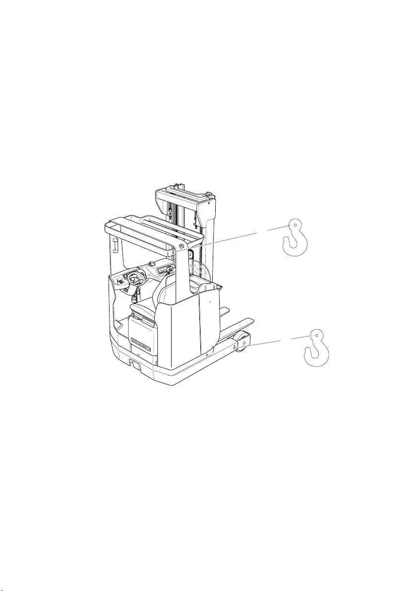
1 Loading and unloading of trucks by crane
m
Ensure that the lifting gear is of adequate capacity (Transportation weight = net
weight + battery weight; see truck identification plate)
– To load the truck with lifting gear, lay the loop of the rope around the strut of the
overhead guard (1). Two lifting points (2) are provided on the wheel arms.
– Park the truck and render it safe (see chapter E).
– Use chocks to prevent the truck from moving!
m
The lifting gear must be secured to the lifting points in such a way that it does not
come into contact with any attachments when the truck is lifted.
Moving the truck without battery
f
The transport restraint prevents the parking brake from being applied. In this state,
the truck is not braked!
– Press the brake pedal. Use the service brake to prevent the truck from moving!
– Remove the safety chocks.
– Release the service brake.
A
The truck can now be pulled or pushed.
1
2
C 1
0699.GB
C Transportation and commissioning
1 Loading and unloading of trucks by crane
m
Ensure that the lifting gear is of adequate capacity (Transportation weight = net
weight + battery weight; see truck identification plate)
– To load the truck with lifting gear, lay the loop of the rope around the strut of the
overhead guard (1). Two lifting points (2) are provided on the wheel arms.
– Park the truck and render it safe (see chapter E).
– Use chocks to prevent the truck from moving!
m
The lifting gear must be secured to the lifting points in such a way that it does not
come into contact with any attachments when the truck is lifted.
Moving the truck without battery
f
The transport restraint prevents the parking brake from being applied. In this state,
the truck is not braked!
– Press the brake pedal. Use the service brake to prevent the truck from moving!
– Remove the safety chocks.
– Release the service brake.
A
The truck can now be pulled or pushed.
1
2
Page 25

0699.GB
C 2
2 Commissioning
m
The truck must only be operated on battery current. Rectified alternate current will damage the electronics. Cables connected to the battery (towing cable) must be less
than 6 meters in length.
To prepare the truck for work following delivery or transportation, the following operations must be performed:
– If necessary, install the battery. Do not damage the battery cable.
– Charge the battery. (see chapter D)
– Remove the transport restraint of the parking brake, if required.
(see chapter C)
– Commission the truck as prescribed. (see chapter E)
A
When supplied without battery, the truck can only be steered using the mechanical
spare steering system (see chapter E).
3 Parking brake transport restraint
f
Before commissioning the truck, the transport restraint must be removed. This device
is used to lock the magnet actuating the parking brake so that the the truck is not braked when no power is available.
The transport restraint is applied if the truck is delivered with an uncharged battery.
The transport restraint consists of a retaining ring (3) attached to a red cable tie which
visibly protrudes from the seat hood. The retaining ring is inserted at the tie rod of the
magnet. This prevents the magnet from moving.
Removing the transport restraint:
– Connect the charged battery.
– Open the seat hood.
(see chapter F)
– Remove the retaining ring (3) with the
cable tie from the tie rod.
m
The second retaining ring inserted at the
tie rod must not be removed during commissioning!
– Close and lock the seat hood.
– Switch on the master switch and the
key switch.
A
The truck is now ready for operation.
3
0699.GB
C 2
2 Commissioning
m
The truck must only be operated on battery current. Rectified alternate current will da-
mage the electronics. Cables connected to the battery (towing cable) must be less
than 6 meters in length.
To prepare the truck for work following delivery or transportation, the following ope-
rations must be performed:
– If necessary, install the battery. Do not damage the battery cable.
– Charge the battery. (see chapter D)
– Remove the transport restraint of the parking brake, if required.
(see chapter C)
– Commission the truck as prescribed. (see chapter E)
A
When supplied without battery, the truck can only be steered using the mechanical
spare steering system (see chapter E).
3 Parking brake transport restraint
f
Before commissioning the truck, the transport restraint must be removed. This device
is used to lock the magnet actuating the parking brake so that the the truck is not bra-
ked when no power is available.
The transport restraint is applied if the truck is delivered with an uncharged battery.
The transport restraint consists of a retaining ring (3) attached to a red cable tie which
visibly protrudes from the seat hood. The retaining ring is inserted at the tie rod of the
magnet. This prevents the magnet from moving.
Removing the transport restraint:
– Connect the charged battery.
– Open the seat hood.
(see chapter F)
– Remove the retaining ring (3) with the
cable tie from the tie rod.
m
The second retaining ring inserted at the
tie rod must not be removed during com-
missioning!
– Close and lock the seat hood.
– Switch on the master switch and the
key switch.
A
The truck is now ready for operation.
3
Page 26

D 1
0699.GB
D Battery - servicing, recharging,
replacement
1 Safety regulations governing the handling of lead-acid batteries
The truck must be parked and rendered safe, before any operations on batteries are
to be undertaken (see Chapter E).
Servicing staff: Recharging, servicing and replacing of batteries must only be performed by qualified personnel. The instructions contained in this operating manual,
and the instructions as prepared by the battery supplier and as available at the battery
recharging station must be observed, when performing the above operations.
Fire protection measures: Smoking and naked flames are not permitted when
handling batteries. No inflammable substances or spark-generating materials must
be present or stored within a distance of 2 meters of the truck parked for battery recharging. The location must be well ventilated and fire fighting equipment must be
kept ready.
Servicing of batteries: The battery cell screw caps must be kept dry and clean. Terminals and cable shoes must be clean, lightly greased with pole grease and must be
securely tightened.
Disposal of the battery: Batteries must only be disposed of as stipulated in the national environmental protection regulations or waste disposal provisions. The manufacturer’s specifications for the disposal must be heeded.
m
Before closing the battery hood, make sure that the battery cable cannot be damaged.
f
Batteries contain dissolved acid, which is toxic and caustic. For this reason protective
clothing and goggles must be worn whenever work is undertaken on batteries. Avoid
physical contact with battery acid. If clothing, skin or eyes have accidentally come into
contact with battery acid, liberally flush the affected parts with clean water. Consult a
doctor, when skin or eyes have come into contact with battery acid. Spilled battery
acid must be immediately neutralized.
D 1
0699.GB
D Battery - servicing, recharging,
replacement
1 Safety regulations governing the handling of lead-acid batteries
The truck must be parked and rendered safe, before any operations on batteries are
to be undertaken (see Chapter E).
Servicing staff: Recharging, servicing and replacing of batteries must only be per-
formed by qualified personnel. The instructions contained in this operating manual,
and the instructions as prepared by the battery supplier and as available at the battery
recharging station must be observed, when performing the above operations.
Fire protection measures: Smoking and naked flames are not permitted when
handling batteries. No inflammable substances or spark-generating materials must
be present or stored within a distance of 2 meters of the truck parked for battery re-
charging. The location must be well ventilated and fire fighting equipment must be
kept ready.
Servicing of batteries: The battery cell screw caps must be kept dry and clean. Ter-
minals and cable shoes must be clean, lightly greased with pole grease and must be
securely tightened.
Disposal of the battery: Batteries must only be disposed of as stipulated in the na-
tional environmental protection regulations or waste disposal provisions. The manu-
facturer’s specifications for the disposal must be heeded.
m
Before closing the battery hood, make sure that the battery cable cannot be dama-
ged.
f
Batteries contain dissolved acid, which is toxic and caustic. For this reason protective
clothing and goggles must be worn whenever work is undertaken on batteries. Avoid
physical contact with battery acid. If clothing, skin or eyes have accidentally come into
contact with battery acid, liberally flush the affected parts with clean water. Consult a
doctor, when skin or eyes have come into contact with battery acid. Spilled battery
acid must be immediately neutralized.
Page 27

0699.GB
D 2
2Battery type
The batteries are designed in accordance with IEC 254 EN 60254.
The table below shows the capacity of the batteries and also the combinations used
as standard equipment:
The battery weights can be seen on the battery identification plate.
Depending on the type of battery used, it is also possible to use models with enhanced performance or maintenance-free batteries.
m
When replacing or installing batteries, ensure that the battery is correctly secured in
the battery compartment of the truck.
f
Battery weight and battery dimensions have a considerable effect on the stability of
the truck. Battery type changes are therefore permitted only after obtaining approval
from the manufacturer.
3 Exposing the battery
– Render the truck ready for operation (see chapter E).
– Tilt the multi-pilot stick (1) in direction of arrow (U), drive mast holder to its limit stop
position towards the battery and release multi-pilot (1) (mast is in final position).
– Tilt the multi-pilot stick (1) once again in direction of arrow (U) and go on driving
mast holder to its limit stop position towards the battery (preparation of battery unlocking).
– Actuate the battery trolley unlocking system (3). The control lamp (4) lights up.
– Tilt the multi-pilot stick (1) in the T direction and push the mast holder with the cou-
pled battery trolley forward until the battery is exposed for servicing.
– Switch off the master switch and the key switch.
f
Connecting and disconnecting of battery connector and socket is permitted only with
the master switch and battery charger switched off.
– Withdraw the battery connector (2) from the socket.
– Remove any insulating matting from the batteries.
A
The safety switch of the battery unlocking system interrupts the driving function as
long as the battery trolley is unlocked and the control lamp (4) is lit. Before commissioning the truck again, the battery trolley must be returned to the original position to
uncouple the battery trolley and the mast holder. The control lamp (4) must have gone
out.
capacity standard (L) performance-enhanced (HX)
48 V - 3PzS - battery 420 Ah X 48 V - 3PzS - battery 450 Ah - X
48 V - 4PzS - battery 560 Ah X 48 V - 4PzS - battery 600 Ah - X
48 V - 5PzS - battery 700 Ah X 48 V - 5PzS - battery 750 Ah - X
48 V - 6PzS - battery 840 Ah X 48 V - 6PzS - battery 900 Ah - X
0699.GB
D 2
2Battery type
The batteries are designed in accordance with IEC 254 EN 60254.
The table below shows the capacity of the batteries and also the combinations used
as standard equipment:
The battery weights can be seen on the battery identification plate.
Depending on the type of battery used, it is also possible to use models with enhan-
ced performance or maintenance-free batteries.
m
When replacing or installing batteries, ensure that the battery is correctly secured in
the battery compartment of the truck.
f
Battery weight and battery dimensions have a considerable effect on the stability of
the truck. Battery type changes are therefore permitted only after obtaining approval
from the manufacturer.
3 Exposing the battery
– Render the truck ready for operation (see chapter E).
– Tilt the multi-pilot stick (1) in direction of arrow (U), drive mast holder to its limit stop
position towards the battery and release multi-pilot (1) (mast is in final position).
– Tilt the multi-pilot stick (1) once again in direction of arrow (U) and go on driving
mast holder to its limit stop position towards the battery (preparation of battery un-
locking).
– Actuate the battery trolley unlocking system (3). The control lamp (4) lights up.
– Tilt the multi-pilot stick (1) in the T direction and push the mast holder with the cou-
pled battery trolley forward until the battery is exposed for servicing.
– Switch off the master switch and the key switch.
f
Connecting and disconnecting of battery connector and socket is permitted only with
the master switch and battery charger switched off.
– Withdraw the battery connector (2) from the socket.
– Remove any insulating matting from the batteries.
A
The safety switch of the battery unlocking system interrupts the driving function as
long as the battery trolley is unlocked and the control lamp (4) is lit. Before commis-
sioning the truck again, the battery trolley must be returned to the original position to
uncouple the battery trolley and the mast holder. The control lamp (4) must have gone
out.
capacity standard (L) performance-enhanced (HX)
48 V - 3PzS - battery 420 Ah X -
48 V - 3PzS - battery 450 Ah - X
48 V - 4PzS - battery 560 Ah X -
48 V - 4PzS - battery 600 Ah - X
48 V - 5PzS - battery 700 Ah X -
48 V - 5PzS - battery 750 Ah - X
48 V - 6PzS - battery 840 Ah X -
48 V - 6PzS - battery 900 Ah - X
Page 28

D 3
0699.GB
3.1 Bypassing the drive current interruption
– Switch on the switch “Cut-back speed” (5).
f
If the battery is protruding, the truck may only be driven at cut-back speed in the battery charging station!
3.2 Battery trolley emergency unlocking system
– Render the truck ready for operation
(see chapter E).
– Tilt multi-pilot stick (1) in direction of
arrow (U), drive mast holder to its limit
stop position towards the battery and
release multi-pilot (1).
– Tilt multi-pilot stick (1) once again in
direction of arrow (U) and go on driving mast holder to its limit stop position towards the battery.
– Switch off the master switch and the
key switch.
– Open seat hood (see chapter F)
– Loosen screws (6) of the battery lok-
king system and pull out locking sy-
stem (7).
– Close seat hood.
– Connect master switch and key switch.
– Tilt the multi-pilot stick (1) in the (T) direction and push the mast holder with the cou-
pled battery trolley forward until the battery is exposed for servicing.
– Control lamp (4) lights up.
– Disconnect main switch and key switch.
A
Eliminate the malfunction of the battery unlocking system before mounting the battery
locking system.
3
U
5
T
1
2
4
6
7
D 3
0699.GB
3.1 Bypassing the drive current interruption
– Switch on the switch “Cut-back speed” (5).
f
If the battery is protruding, the truck may only be driven at cut-back speed in the bat-
tery charging station!
3.2 Battery trolley emergency unlocking system
– Render the truck ready for operation
(see chapter E).
– Tilt multi-pilot stick (1) in direction of
arrow (U), drive mast holder to its limit
stop position towards the battery and
release multi-pilot (1).
– Tilt multi-pilot stick (1) once again in
direction of arrow (U) and go on dri-
ving mast holder to its limit stop positi-
on towards the battery.
– Switch off the master switch and the
key switch.
– Open seat hood (see chapter F)
– Loosen screws (6) of the battery lok-
king system and pull out locking sy-
stem (7).
– Close seat hood.
– Connect master switch and key switch.
– Tilt the multi-pilot stick (1) in the (T) direction and push the mast holder with the cou-
pled battery trolley forward until the battery is exposed for servicing.
– Control lamp (4) lights up.
– Disconnect main switch and key switch.
A
Eliminate the malfunction of the battery unlocking system before mounting the battery
locking system.
3
U
5
T
1
2
4
6
7
Page 29

0699.GB
D 4
A
The safety switch of the battery unlocking system interrupts the driving function as
long as the battery trolley is unlocked and the control lamp (4) is lit. Before commissioning the truck again, the battery trolley must be returned to the original position to
uncouple the battery trolley and the mast holder. The control lamp (4) must have gone
out.
4 Charging the battery
– Expose the battery (see chapter D).
f
During the recharging operation the tops of the battery cells must be exposed to ensure adequate ventilation. No metal objects must be placed on the battery. Prior to
starting the recharging operation, check all cable connections and plugged connections for visible damage.
– Remove any insulating mats from the battery.
– Connect the charging cable of the battery charger to the battery connector (2).
– Recharge the battery observing the instructions provided by the battery supplier
and by the battery charger supplier.
f
All safety instructions as provided by the battery supplier and battery charger supplier
must be strictly observed.
0699.GB
D 4
A
The safety switch of the battery unlocking system interrupts the driving function as
long as the battery trolley is unlocked and the control lamp (4) is lit. Before commis-
sioning the truck again, the battery trolley must be returned to the original position to
uncouple the battery trolley and the mast holder. The control lamp (4) must have gone
out.
4 Charging the battery
– Expose the battery (see chapter D).
f
During the recharging operation the tops of the battery cells must be exposed to en-
sure adequate ventilation. No metal objects must be placed on the battery. Prior to
starting the recharging operation, check all cable connections and plugged connec-
tions for visible damage.
– Remove any insulating mats from the battery.
– Connect the charging cable of the battery charger to the battery connector (2).
– Recharge the battery observing the instructions provided by the battery supplier
and by the battery charger supplier.
f
All safety instructions as provided by the battery supplier and battery charger supplier
must be strictly observed.
Page 30

D 5
0699.GB
5 Removing and installing the battery
– Expose the battery (see section 3).
f
Batteries with open poles, or open cell bridges, must be covered with a rubber mat to
prevent short-circuiting. When using a crane in battery replacing operations, ensure
that the crane is of adequate capacity (see the battery weight indicated on the battery
identification plate located at the battery trough). The battery must be lifted vertically
to prevent crushing of the battery trough. Lifting hooks must be applied in such a way
that, with the lifting gear slack, they will not drop on to the battery cells.
Removing and installing the battery using lifting gear
– Secure the lifting gear to the battery trough (8).
– Loosen counternut (10) and screw (11) at the red battery lock (9).
– Pull out the red battery lock (9).
– With the lifting gear attached, lift out the battery and move it to one side.
Installation is in the reverse order of operations.
Removing and installing the battery using a battery trolley
f
The truck must stand horizontally so that the battery does not automatically roll out
when the battery safety device is removed.
– Use the service key to open the side door (12).
– Loosen counternut (10) and screw (11) at the red battery lock (9).
– Pull out the red battery lock (9).
– Pull the battery laterally onto the battery transport trolley.
Installation is in the reverse order of operations.
f
When replacing batteries, ensure that a battery of the same type is fitted. Upon completion of the battery refitting operations, check all cable connections and plugged
connections for any visible damage. Covers and side doors must be safely locked.
10
11
9
8
12
D 5
0699.GB
5 Removing and installing the battery
– Expose the battery (see section 3).
f
Batteries with open poles, or open cell bridges, must be covered with a rubber mat to
prevent short-circuiting. When using a crane in battery replacing operations, ensure
that the crane is of adequate capacity (see the battery weight indicated on the battery
identification plate located at the battery trough). The battery must be lifted vertically
to prevent crushing of the battery trough. Lifting hooks must be applied in such a way
that, with the lifting gear slack, they will not drop on to the battery cells.
Removing and installing the battery using lifting gear
– Secure the lifting gear to the battery trough (8).
– Loosen counternut (10) and screw (11) at the red battery lock (9).
– Pull out the red battery lock (9).
– With the lifting gear attached, lift out the battery and move it to one side.
Installation is in the reverse order of operations.
Removing and installing the battery using a battery trolley
f
The truck must stand horizontally so that the battery does not automatically roll out
when the battery safety device is removed.
– Use the service key to open the side door (12).
– Loosen counternut (10) and screw (11) at the red battery lock (9).
– Pull out the red battery lock (9).
– Pull the battery laterally onto the battery transport trolley.
Installation is in the reverse order of operations.
f
When replacing batteries, ensure that a battery of the same type is fitted. Upon com-
pletion of the battery refitting operations, check all cable connections and plugged
connections for any visible damage. Covers and side doors must be safely locked.
10
11
9
8
12
Page 31

0699.GB
D 6
6 Battery discharge indicator, battery discharge monitor and hour meter
Battery discharge indicator: The charging state of the battery (13) is indicated in
10% steps in the LISA display.
m
The standard setting of the battery discharge indicator / discharge monitor is
made using standard batteries..
When using maintenance-free batteries,
the indication has to be adjusted in a
way that the symbol (T) (14) comes up
behind the percent indication. When this
setting is not performed, the battery
might suffer damage caused by exhaustive discharge.
Setting of the instrument should be performed by service staff from the manufacturer of the truck.
In case of a rest capacity of the battery of
20% for standard batteries or
40% for maintenance-free batteries, a
battery charge is necessary.
Battery discharge monitor: In case of undershooting the rest capacity the lifting
function is disconnected. LISA indicates a corresponding message.
A
Lifting will only become possible again, after the battery has been recharged to at
least 70 per cent.
Hour meter: The service hours (15) are indicated besides the charging state of the
battery. The hour meter indicates the overall time of the driving and the lifting movements.
BAT T T:0 0%4471h
13 14 15
0699.GB
D 6
6 Battery discharge indicator, battery discharge monitor and hour meter
Battery discharge indicator: The charging state of the battery (13) is indicated in
10% steps in the LISA display.
m
The standard setting of the battery di-
scharge indicator / discharge monitor is
made using standard batteries..
When using maintenance-free batteries,
the indication has to be adjusted in a
way that the symbol (T) (14) comes up
behind the percent indication. When this
setting is not performed, the battery
might suffer damage caused by exhau-
stive discharge.
Setting of the instrument should be per-
formed by service staff from the manu-
facturer of the truck.
In case of a rest capacity of the battery of
20% for standard batteries or
40% for maintenance-free batteries, a
battery charge is necessary.
Battery discharge monitor: In case of undershooting the rest capacity the lifting
function is disconnected. LISA indicates a corresponding message.
A
Lifting will only become possible again, after the battery has been recharged to at
least 70 per cent.
Hour meter: The service hours (15) are indicated besides the charging state of the
battery. The hour meter indicates the overall time of the driving and the lifting move-
ments.
BAT T T:0 0%4471h
13 14 15
Page 32

E 1
0903.GB
E Operation
1 Safety regulations governing the operation of the truck
Driving permission: The truck must only be operated by persons who have been
trained in the operation of trucks, who have demonstrated to the user or his representative their capability of moving and handling loads, and who have expressly been
charged by the user or his representative with the operation of the truck.
Rights, duties and conduct of the driver: The driver must be: informed of his rights
and duties; trained in the operation of the fork-lift truck; and familiar with the contents
of these operating instructions. All necessary rights must be granted to him. If the
fork-lift truck can be used in the pedestrian-controlled mode, the driver must wear
safety boots when operating the truck.
Prohibition of unauthorized use: The driver is responsible for his truck during working time. He must forbid unauthorized persons to drive or operate the truck. The
transport or lifting of persons is forbidden.
Damage and defects: Damage or defects noted on the truck or on the attachments
must immediately be brought to the notice of the person in charge. Trucks that cannot
be safely operated (e.g. due to worn tyres or defective brakes) must not be used until
they have been properly repaired.
Repairs: Without specific training and express authorization the driver is not allowed
to perform any repairs or modifications on the truck. Under no circumstances must
the driver change the setting of switches or safety installations, or render them ineffective.
Danger area: As danger area is considered the area within which persons are endangered by the travelling or lifting movements of the truck or its load lifting devices (e.g.
fork or attachments), or by the loads being transported. This includes also the area
within reach of dropping loads or dropping truck attachments.
f
Unauthorized persons must be asked to leave the danger area. The driver must give
a warning signal, whenever a situation presenting danger to persons might develop.
The truck must immediately be brought to a standstill, if persons, although asked, do
not leave the danger area.
Safety devices and warning labels: The safety devices, warning labels and warning
notes described in the present operating instructions must always be heeded.
E 1
0903.GB
E Operation
1 Safety regulations governing the operation of the truck
Driving permission: The truck must only be operated by persons who have been
trained in the operation of trucks, who have demonstrated to the user or his represen-
tative their capability of moving and handling loads, and who have expressly been
charged by the user or his representative with the operation of the truck.
Rights, duties and conduct of the driver: The driver must be: informed of his rights
and duties; trained in the operation of the fork-lift truck; and familiar with the contents
of these operating instructions. All necessary rights must be granted to him. If the
fork-lift truck can be used in the pedestrian-controlled mode, the driver must wear
safety boots when operating the truck.
Prohibition of unauthorized use: The driver is responsible for his truck during wor-
king time. He must forbid unauthorized persons to drive or operate the truck. The
transport or lifting of persons is forbidden.
Damage and defects: Damage or defects noted on the truck or on the attachments
must immediately be brought to the notice of the person in charge. Trucks that cannot
be safely operated (e.g. due to worn tyres or defective brakes) must not be used until
they have been properly repaired.
Repairs: Without specific training and express authorization the driver is not allowed
to perform any repairs or modifications on the truck. Under no circumstances must
the driver change the setting of switches or safety installations, or render them inef-
fective.
Danger area: As danger area is considered the area within which persons are endan-
gered by the travelling or lifting movements of the truck or its load lifting devices (e.g.
fork or attachments), or by the loads being transported. This includes also the area
within reach of dropping loads or dropping truck attachments.
f
Unauthorized persons must be asked to leave the danger area. The driver must give
a warning signal, whenever a situation presenting danger to persons might develop.
The truck must immediately be brought to a standstill, if persons, although asked, do
not leave the danger area.
Safety devices and warning labels: The safety devices, warning labels and warning
notes described in the present operating instructions must always be heeded.
Page 33

0903.GB
E 2
2 Description of the operating controls and indicators
Item Operating
control /indicator
Function
1 Multi-pilot stick t Operates the following functions:
Forward / reverse drive direction
Lifting / lowering the load lifting device
Pushing forward / retracting the mast holder
Tilting the hoist frame forward / backward
Moving the lateral traversing device to the left /
right
Horn key
2 Control lever ZH 2 o Controls the second auxiliary hydraulic system.
3 Switch - emergency
steering
t Bypasses the steering control system.
4 Driver seat lock t Horizontal adjustment of the driver seat.
5 Driver seat weight
adjustment
t Setting of driver weight for optimum seat dam-
ping.
6 Foot key t – not pressed: The driving and lifting functions,
as well as the auxiliary functions, are locked.
The lowering function remains functional. The
truck rolls to a stop.
– pressed: The driving and lifting functions, as
well as the auxiliary functions, are released.
7 Double pedal o Regulates driving direction and speed
8 Brake pedal t Braking of the truck.
9 Accelerator t Stepless control of the truck travelling speed.
10 Backrest adjustment t Adjustment of the driver seat backrest.
11 Steering column adju-
sting mechanism
t The steering column is adjusted to the required
distance and locked in that position.
12 Battery trolley unlocking
system
t Unlocks the battery trolley.
13 Parking brake t Prevents the truck from moving when parked.
t = Standard equipment o = Optional equipment
Page 34

E 3
0903.GB
E 3
0903.GB
Page 35

0903.GB
E 4
Item Operating
control /indicator
Function
14 Key switch with key t For connection and disconnection of the battery
voltage to the truck.
A
Red key (No. 702):
- for the user
Grey key (No. 738):
- for service and workshop
15 Switch -
cut-back speed
t Switches cut-back speed on and off.
16 Master switch
(emergency stop)
t The circuit is interrupted, all electrical functions
are switched off and automatic braking of the
truck is triggered.
17 Information and service
display (LISA)
t Display of essential driving parameters, lifting
parameters, warning signals, operating error indications and service indications
t = Standard equipment o = Optional equipment
0903.GB
E 4
Item Operating
control /indicator
Function
14 Key switch with key t For connection and disconnection of the battery
voltage to the truck.
A
Red key (No. 702):
- for the user
Grey key (No. 738):
- for service and workshop
15 Switch -
cut-back speed
t Switches cut-back speed on and off.
16 Master switch
(emergency stop)
t The circuit is interrupted, all electrical functions
are switched off and automatic braking of the
truck is triggered.
17 Information and service
display (LISA)
t Display of essential driving parameters, lifting
parameters, warning signals, operating error in-
dications and service indications
t = Standard equipment o = Optional equipment
Page 36

E 5
0903.GB
E 5
0903.GB
Page 37

0903.GB
E 6
3 Start-up of truck
f
The driver must make sure that nobody is within the danger area of the truck, before
the truck is switched on or operated, or before a load is lifted.
Checks and operations to be performed before starting daily work
– Perform a visual check of the entire truck (especially wheels and load lifting equip-
ment) for visible damage.
– Check the load chains for uniform tension.
– Visually check the security of the battery and the cable connections.
Adjusting the driver seat
A
To ensure optimum shock absorption, the driver seat must be adjusted to the weight
of the driver.
The driver seat must not be occupied while being adjusted to the driver weight.
Setting the driver weight:
– Pull the lever (5) in the direction indi-
cated by the arrow and release it
again.
A
The previously set driver weight is reset
to the minimum value. Setting range for
the shock absorption: 50 kg to 130 kg.
– Pull the lever (5) again in the direction
indicated indicated by the arrow until
reaching the ap-propriate weight mark
on the scale (17). Then release the le-
ver again.
– Sit down on the driver seat.
f
Do not reach between the seat and the
chassis wall/overhead guard.
Adjusting the backrest:
– Pull the locking lever (10) upward and adjust the inclination of the backrest (19).
– Release the locking lever again, the backrest is locked in position.
Adjusting the seat position:
– Pull the locking lever (4) of the driver seat locking system outward and move the
driver seat forward or backward to a comfortable position.
– Let the locking lever (4) engage again.
f
The driver seat locking system must be properly engaged in the set position. The position of the seat must not be changed while driving!
A
The driver seat adjusting mechanism shown relates to the standard version. For all
different designs the adjusting instructions as supplied by the manufacturer apply.
When performing the seat adjustments, ensure that all operating controls are within
easy reach.
10
18
5
4
19
0903.GB
E 6
3 Start-up of truck
f
The driver must make sure that nobody is within the danger area of the truck, before
the truck is switched on or operated, or before a load is lifted.
Checks and operations to be performed before starting daily work
– Perform a visual check of the entire truck (especially wheels and load lifting equip-
ment) for visible damage.
– Check the load chains for uniform tension.
– Visually check the security of the battery and the cable connections.
Adjusting the driver seat
A
To ensure optimum shock absorption, the driver seat must be adjusted to the weight
of the driver.
The driver seat must not be occupied while being adjusted to the driver weight.
Setting the driver weight:
– Pull the lever (5) in the direction indi-
cated by the arrow and release it
again.
A
The previously set driver weight is reset
to the minimum value. Setting range for
the shock absorption: 50 kg to 130 kg.
– Pull the lever (5) again in the direction
indicated indicated by the arrow until
reaching the ap-propriate weight mark
on the scale (17). Then release the le-
ver again.
– Sit down on the driver seat.
f
Do not reach between the seat and the
chassis wall/overhead guard.
Adjusting the backrest:
– Pull the locking lever (10) upward and adjust the inclination of the backrest (19).
– Release the locking lever again, the backrest is locked in position.
Adjusting the seat position:
– Pull the locking lever (4) of the driver seat locking system outward and move the
driver seat forward or backward to a comfortable position.
– Let the locking lever (4) engage again.
f
The driver seat locking system must be properly engaged in the set position. The po-
sition of the seat must not be changed while driving!
A
The driver seat adjusting mechanism shown relates to the standard version. For all
different designs the adjusting instructions as supplied by the manufacturer apply.
When performing the seat adjustments, ensure that all operating controls are within
easy reach.
10
18
5
4
19
Page 38

E 7
0903.GB
Adjusting the steering column
– Release the steering column locking
mechanism (10) and adjust the incli-
nation and the height of the steering
column (19) as required.
– Tighten steering column locking me-
chanism.
3.1 How to use the safety belt o
f
Read this section completely before
starting up the floor conveyor.
– Fasten the belt before performing any
movement of the floor conveyor.
– Adjust the belt height setting (52) ac-
cording to your size.
f
The belt protects you against severe injuries.
– If the belt buckle (50) or the belt reel-
up device is frozen in, let it thaw and
dry.
m
The temperature of the warm air-stream
must not exceed +60°C.
f
Do not modify the safety belt.
– After an accident has occurred, check
the safety belt and the seating cover
for damages. Exchange them, if requi-
red.
– Damaged or not fully functioning safety belts may only be exchanged by contract
dealers or branches.
– Only original spare parts may be used for upgrading or repairs.
14 16
1120
17
52
50 51
E 7
0903.GB
Adjusting the steering column
– Release the steering column locking
mechanism (10) and adjust the incli-
nation and the height of the steering
column (19) as required.
– Tighten steering column locking me-
chanism.
3.1 How to use the safety belt o
f
Read this section completely before
starting up the floor conveyor.
– Fasten the belt before performing any
movement of the floor conveyor.
– Adjust the belt height setting (52) ac-
cording to your size.
f
The belt protects you against severe in-
juries.
– If the belt buckle (50) or the belt reel-
up device is frozen in, let it thaw and
dry.
m
The temperature of the warm air-stream
must not exceed +60°C.
f
Do not modify the safety belt.
– After an accident has occurred, check
the safety belt and the seating cover
for damages. Exchange them, if requi-
red.
– Damaged or not fully functioning safety belts may only be exchanged by contract
dealers or branches.
– Only original spare parts may be used for upgrading or repairs.
14 16
1120
17
52
50 51
Page 39

0903.GB
E 8
o Behaviour in unusual situations
m
Proceed as follows, if there is danger of the floor conveyor tipping over.
– Press the upper part of your body against the the backrest.
– Keep both hands at the steering wheel and use your feed for
additional support.
– Bend your body against the falling direction.
o Operating instruction of the safety belt
Before starting up the floor conveyor, pull the belt continuously out of the reel-up device and let it catch in with the belt fitting tight to your body.
f
The belt must not be twisted when being fastened.
When operating the floor conveyor (e.g. driving, lifting, lowering,
etc.) always try to sit with your back having contact with the
backrest.
The locking mechanism of the reel-up device permits enough
freedom of motion when sitting.
f
If you are sitting on the front edge of the seat, protecton will decrease due to the belt band being too loose.
A
Use the belt only for protecting one person.
– After using the belt, press the red button and direct the belt
locking tongue back to the reel-up device with your hand.
o Behaviour for starting up the floor conveyor on steep slopes
The locking mechanism blocks the belt drawing mechanism if the floor conveyor is
parked on a steep slope. The belt can no longer be pulled out of the reel-up device.
A
Drive the floor conveyor carefully out of its slope position and fasten the belt.
0903.GB
E 8
o Behaviour in unusual situations
m
Proceed as follows, if there is danger of the floor conveyor tipping over.
– Press the upper part of your body against the the backrest.
– Keep both hands at the steering wheel and use your feed for
additional support.
– Bend your body against the falling direction.
o Operating instruction of the safety belt
Before starting up the floor conveyor, pull the belt continuously out of the reel-up de-
vice and let it catch in with the belt fitting tight to your body.
f
The belt must not be twisted when being fastened.
When operating the floor conveyor (e.g. driving, lifting, lowering,
etc.) always try to sit with your back having contact with the
backrest.
The locking mechanism of the reel-up device permits enough
freedom of motion when sitting.
f
If you are sitting on the front edge of the seat, protecton will de-
crease due to the belt band being too loose.
A
Use the belt only for protecting one person.
– After using the belt, press the red button and direct the belt
locking tongue back to the reel-up device with your hand.
o Behaviour for starting up the floor conveyor on steep slopes
The locking mechanism blocks the belt drawing mechanism if the floor conveyor is
parked on a steep slope. The belt can no longer be pulled out of the reel-up device.
A
Drive the floor conveyor carefully out of its slope position and fasten the belt.
Page 40

E 9
0903.GB
Switching on the truck
– Pull up the master switch (16).
– Insert the key in the key switch (14)
and turn clockwise against the stop to
position "I".
– Check the horn for proper function.
The truck is now ready for operation.The
battery discharge monitor shows the
current battery capacity.
– Check the brake pedal and the par-
king brake for correct functioning
(see section 4.2).
3.2 Emergency stop device
A
The truck is equipped with an emergency stop device. After connecting the master
switch (16) and the key switch (14) an automatic safety inquiry is performed.
Emergency stop indication
LISA (17) displays an indication after recognizing a trouble in the steering system or
in the braking system (see section 5).
Triggering of an emergency stop
If a malfunction endangering the safety of the operator occurs in the steering system
while driving, the truck is automatically braked in a controlled manner until it is at a
standstill.
Resetting an emergency stop
– Switch the master switch and the key switch off and then on again.
A
If the emergency-stop indication appears on the LISA display even after repeatedly
performing the emergency-stop reset, contact the customer service of the manufacturer for further troobleshooting.
m
If the truck is in a danger zone or between racks after an emergency stop has been
triggered, the truck can only be moved and thus recovered by means of the mechanical stand-by steering system! (see section 7)
14 16
1120
17
E 9
0903.GB
Switching on the truck
– Pull up the master switch (16).
– Insert the key in the key switch (14)
and turn clockwise against the stop to
position "I".
– Check the horn for proper function.
The truck is now ready for operation.The
battery discharge monitor shows the
current battery capacity.
– Check the brake pedal and the par-
king brake for correct functioning
(see section 4.2).
3.2 Emergency stop device
A
The truck is equipped with an emergency stop device. After connecting the master
switch (16) and the key switch (14) an automatic safety inquiry is performed.
Emergency stop indication
LISA (17) displays an indication after recognizing a trouble in the steering system or
in the braking system (see section 5).
Triggering of an emergency stop
If a malfunction endangering the safety of the operator occurs in the steering system
while driving, the truck is automatically braked in a controlled manner until it is at a
standstill.
Resetting an emergency stop
– Switch the master switch and the key switch off and then on again.
A
If the emergency-stop indication appears on the LISA display even after repeatedly
performing the emergency-stop reset, contact the customer service of the manufac-
turer for further troobleshooting.
m
If the truck is in a danger zone or between racks after an emergency stop has been
triggered, the truck can only be moved and thus recovered by means of the mecha-
nical stand-by steering system! (see section 7)
14 16
1120
17
Page 41

0903.GB
E 10
4 Truck operation
4.1 Safety regulations applicable when operating the truck
Driving lanes and work areas: Only such lanes and routes that are specially alloca-
ted for truck traffic must be used. Unauthorized persons must stay away from work
areas. Loads must only be stored at places specially provided for this purpose.
Driving conduct: The travelling speed must be adapted to the prevailing local conditions. The truck must be driven at slow speed when negotiating bends or narrow
passages, when passing through swing doors and at blind spots. The driver must always observe an adequate braking distance between his truck and the vehicle in front
and he must be in control of his truck at all times. Sudden stopping (except in emergencies), rapid U-turns and overtaking at dangerous or blind spots is not permitted. It
is forbidden to lean out of or reach beyond the working and operating area.
Visibility: The driver must look in the direction of travel and must always have a clear
view of the route ahead. When loads blocking the view are carried, the truck must be
driven with the load at the rear. If this is not possible, a second person must walk in
front of the truck to give suitable warnings.
Negotiating slopes and inclines: Negotiating of slopes and inclines is permitted only, when they are recognized lanes, when they are clean and non-slipping, and when
the technical specification of the truck permits safe driving on such slopes or inclines.
Loads must always be carried at that end of the truck facing uphill. U-turns, cutting
obliquely over slopes or inclines and parking of the truck on slopes or inclines is not
permitted. Inclines must only be negotiated at slow speed with the driver ready to brake at any moment.
Use of lifts and driving on loading platforms: Lifts and loading platforms must only
be used, if they are of adequate load bearing capacity, if suitable for driving on, and
if authorized by the user of the truck for truck traffic. The truck driver has to satisfy
himself accordingly before driving into lifts or on to loading platforms. The truck must
enter lifts with the load in front and must take up a position which does not allow it to
come into contact with the walls of the lift shaft. Persons riding in the lift together with
the truck must only enter the lift after the truck has come safely to a standstill, and
must leave the lift before the truck.
Nature of the loads carried: Only loads that have been safely and correctly secured
must be carried. Never transport loads stacked higher than the top of the fork carriage, or stacked higher than the guard grille.
0903.GB
E 10
4 Truck operation
4.1 Safety regulations applicable when operating the truck
Driving lanes and work areas: Only such lanes and routes that are specially alloca-
ted for truck traffic must be used. Unauthorized persons must stay away from work
areas. Loads must only be stored at places specially provided for this purpose.
Driving conduct: The travelling speed must be adapted to the prevailing local con-
ditions. The truck must be driven at slow speed when negotiating bends or narrow
passages, when passing through swing doors and at blind spots. The driver must al-
ways observe an adequate braking distance between his truck and the vehicle in front
and he must be in control of his truck at all times. Sudden stopping (except in emer-
gencies), rapid U-turns and overtaking at dangerous or blind spots is not permitted. It
is forbidden to lean out of or reach beyond the working and operating area.
Visibility: The driver must look in the direction of travel and must always have a clear
view of the route ahead. When loads blocking the view are carried, the truck must be
driven with the load at the rear. If this is not possible, a second person must walk in
front of the truck to give suitable warnings.
Negotiating slopes and inclines: Negotiating of slopes and inclines is permitted on-
ly, when they are recognized lanes, when they are clean and non-slipping, and when
the technical specification of the truck permits safe driving on such slopes or inclines.
Loads must always be carried at that end of the truck facing uphill. U-turns, cutting
obliquely over slopes or inclines and parking of the truck on slopes or inclines is not
permitted. Inclines must only be negotiated at slow speed with the driver ready to bra-
ke at any moment.
Use of lifts and driving on loading platforms: Lifts and loading platforms must only
be used, if they are of adequate load bearing capacity, if suitable for driving on, and
if authorized by the user of the truck for truck traffic. The truck driver has to satisfy
himself accordingly before driving into lifts or on to loading platforms. The truck must
enter lifts with the load in front and must take up a position which does not allow it to
come into contact with the walls of the lift shaft. Persons riding in the lift together with
the truck must only enter the lift after the truck has come safely to a standstill, and
must leave the lift before the truck.
Nature of the loads carried: Only loads that have been safely and correctly secured
must be carried. Never transport loads stacked higher than the top of the fork carria-
ge, or stacked higher than the guard grille.
Page 42

E 11
0903.GB
4.2 Driving, steering, braking
Emergency cut-out
– Depress the master switch (16).
This will switch off all electric functions.
Functioning of the switch must not be affected by object placed on it.
Driving
f
Do not drive the truck unless the hoods
are closed and locked in the stipulated
manner.
The main direction of travel is in the direction of the drive (V). Be especially careful when driving in the direction of the
load (R).
A
The truck should only be driven in the direction of the load (R) for positioning purposes and for picking up or depositing loads.
– Render truck ready for operation (see section 3).
– Release the parking brake (13).
– Set the travel direction switch (21) to the desired travelling direction (V or R).
– Press the accelerator pedal (9) and the foot key (6).
The truck will now move in the selected direction.
f
The foot key (6) prevents the operator's foot from protuding beyond the truck's contour while driving.
If it is not pressed, all electrical func-tions except for the steering, the information and
service display (LISA), the horn and the battery discharge indicator are deactivated.
The truck rolls to a stop.
The lowering function remains functional.
A
The travelling speed is controlled by means of the accelerator (9).
o Douple-pedal version
Driving
Floor conveyors from the double-pedal
series are provided with two pedals
which can be used for selecting the driving direction. They can also be used for
regulating the driving speed.
Driving pedal 7.1: Driving in fork direc-
tion.
Driving pedal 7.2: Driving in actuation di-
rection.
When driving, both feet are to kept on
the pedals.
R
V
16
21
13
9
6
E 11
0903.GB
4.2 Driving, steering, braking
Emergency cut-out
– Depress the master switch (16).
This will switch off all electric functions.
Functioning of the switch must not be af-
fected by object placed on it.
Driving
f
Do not drive the truck unless the hoods
are closed and locked in the stipulated
manner.
The main direction of travel is in the di-
rection of the drive (V). Be especially ca-
reful when driving in the direction of the
load (R).
A
The truck should only be driven in the direction of the load (R) for positioning purpo-
ses and for picking up or depositing loads.
– Render truck ready for operation (see section 3).
– Release the parking brake (13).
– Set the travel direction switch (21) to the desired travelling direction (V or R).
– Press the accelerator pedal (9) and the foot key (6).
The truck will now move in the selected direction.
f
The foot key (6) prevents the operator's foot from protuding beyond the truck's con-
tour while driving.
If it is not pressed, all electrical func-tions except for the steering, the information and
service display (LISA), the horn and the battery discharge indicator are deactivated.
The truck rolls to a stop.
The lowering function remains functional.
A
The travelling speed is controlled by means of the accelerator (9).
o Douple-pedal version
Driving
Floor conveyors from the double-pedal
series are provided with two pedals
which can be used for selecting the dri-
ving direction. They can also be used for
regulating the driving speed.
Driving pedal 7.1: Driving in fork direc-
tion.
Driving pedal 7.2: Driving in actuation di-
rection.
When driving, both feet are to kept on
the pedals.
R
V
16
21
13
9
6
Page 43

0903.GB
E 12
Steering
Contradirectional steering (standard version)
When travelling forward (travel direction switch (21) set to (V) = drive direction),
turning the steering wheel to the left results in a left turn and turning the wheel to the
right in a right turn.
The position of the drive wheel is shown on the LISA display.
o Synchronized steering
When travelling forward (travel direction switch (21) set to (V) = drive direction),
turning the steering wheel to the left results in a right turn and turning the wheel to the
right to a left turn.
The position of the drive wheel is shown on the LISA display.
Braking
A
The braking behaviour of the truck strongly depends on the state of the floor. This
must be taken into account by the driver for his driving behaviour.
The truck can be braked in three ways:
– by counter-current braking,
– by coasting, or by
– using the service brake.
f
If the truck is operated by several drivers
(for instance in multi-shift operations),
the braking and travelling behaviour of
the truck must be checked, when the parameters are individually set. Check the
truck reactions when taking over the
truck.
Counter-current braking:
– Change over the travelling direction
switch (21) during travel to the opposi-
te driving direction. The truck is then
braked by the drive current control system until movement in the opposite direction
commences.
A
This mode of braking reduces energy consumption, as it involves energy recovery via
the drive current control system.
Braking by coasting:
– Slowly release the accelerator pedal while driving. The truck is braked by the drive
current control according to the position of the accelerator pedal.
Braking using the service brake:
– Depress the brake pedal (8).
A
The vehicle is braked by hydraulic drum brakes.
0903.GB
E 12
Steering
Contradirectional steering (standard version)
When travelling forward (travel direction switch (21) set to (V) = drive direction),
turning the steering wheel to the left results in a left turn and turning the wheel to the
right in a right turn.
The position of the drive wheel is shown on the LISA display.
o Synchronized steering
When travelling forward (travel direction switch (21) set to (V) = drive direction),
turning the steering wheel to the left results in a right turn and turning the wheel to the
right to a left turn.
The position of the drive wheel is shown on the LISA display.
Braking
A
The braking behaviour of the truck strongly depends on the state of the floor. This
must be taken into account by the driver for his driving behaviour.
The truck can be braked in three ways:
– by counter-current braking,
– by coasting, or by
– using the service brake.
f
If the truck is operated by several drivers
(for instance in multi-shift operations),
the braking and travelling behaviour of
the truck must be checked, when the pa-
rameters are individually set. Check the
truck reactions when taking over the
truck.
Counter-current braking:
– Change over the travelling direction
switch (21) during travel to the opposi-
te driving direction. The truck is then
braked by the drive current control system until movement in the opposite direction
commences.
A
This mode of braking reduces energy consumption, as it involves energy recovery via
the drive current control system.
Braking by coasting:
– Slowly release the accelerator pedal while driving. The truck is braked by the drive
current control according to the position of the accelerator pedal.
Braking using the service brake:
– Depress the brake pedal (8).
A
The vehicle is braked by hydraulic drum brakes.
Page 44

E 13
0903.GB
4.3 Adjusting the fork tines
f
To ensure safe picking up of loads, the tines should be apart as far as possible
and set centrally to the truck. The load
centre must be located centrally between the fork tines.
– Swivel the locking lever (22) upwards.
– Push the fork tines (23) along the fork
carrier (24) to the required position.
– Swivel the locking lever downwards
and deplace the fork until it engages a
groove.
4.4 Picking up and setting down loads
m
Before picking up a load, the driver has
to check that the load rests properly on
its pallet and that it does not exceed the
capacity of his truck.
– Pass the fork tines as far as possible
under the load.
Lifting
f
Persons must not be allowed to stand
under raised forks.
Pull the multi-pilot stick (1) in the (H) direction.
A
The inclination angle of the multi-pilot
stick controls the lifting speed.
– Do not release the multi-pilot stick until
the desired lifting height has been rea-
ched.
A
If the fork moves against the end stop
(audible noise emitted by the pressure limiting valve), the multi-pilot stick must
immediately be returned to its neutral position.
Lowering
– Push the multi-pilot stick (1) in the (S) direction.
A
The inclination angle of the multi-pilot stick controls the lowering speed.
m
Avoid impacting of the load to prevent damage to the load and to the racking.
23
22
24
1
H
S
U
T
E 13
0903.GB
4.3 Adjusting the fork tines
f
To ensure safe picking up of loads, the ti-
nes should be apart as far as possible
and set centrally to the truck. The load
centre must be located centrally bet-
ween the fork tines.
– Swivel the locking lever (22) upwards.
– Push the fork tines (23) along the fork
carrier (24) to the required position.
– Swivel the locking lever downwards
and deplace the fork until it engages a
groove.
4.4 Picking up and setting down loads
m
Before picking up a load, the driver has
to check that the load rests properly on
its pallet and that it does not exceed the
capacity of his truck.
– Pass the fork tines as far as possible
under the load.
Lifting
f
Persons must not be allowed to stand
under raised forks.
Pull the multi-pilot stick (1) in the (H) di-
rection.
A
The inclination angle of the multi-pilot
stick controls the lifting speed.
– Do not release the multi-pilot stick until
the desired lifting height has been rea-
ched.
A
If the fork moves against the end stop
(audible noise emitted by the pressure li-
miting valve), the multi-pilot stick must
immediately be returned to its neutral po-
sition.
Lowering
– Push the multi-pilot stick (1) in the (S) direction.
A
The inclination angle of the multi-pilot stick controls the lowering speed.
m
Avoid impacting of the load to prevent damage to the load and to the racking.
23
22
24
1
H
S
U
T
Page 45

0903.GB
E 14
4.4.1 Lowering in case of emergency
f
No personnel must be in the danger area when the emergency lowering device is
being used.
If the hoist frame cannot be lowered due to a malfunction of the lifting control system,
the emergency lowering valve (24) on the rear of the mast holder must be actuated.
f
Do not actuate the emergency lowering
valve unless you are standing next to the
truck!
Do not reach through the hoist frame to
actuate the valve!
– Switch off the master switch and the
key switch.
– Pull out the battery plug.
– Press the red valve button down and
keep it in this position (if necessary,
use a suitable extension).
– Slowly lower the hoist frame and the
load lifting device.
f
The truck must not be used until the malfunction has been eliminated.
4.4.2 Lowering in case of emergency - Regenerative lowering o
f
No personnel must be in the danger area when the emergency lowering device is
being used.
If the hoist frame cannot be lowered due
to a malfunction of the lifting control system, the emergency lowering valve (25)
on the load holding valve block below
the driver’s seat hood must be actuated.
– Switch off the master switch and the
key switch.
– Pull out the battery plug.
– Open the seat hood
(see chapter F).
– Open the emergency lowering valve
and slowly lower the hoist frame and
the load lifting device.
f
The truck must not be used until the malfunction has been eliminated.
24
25
0903.GB
E 14
4.4.1 Lowering in case of emergency
f
No personnel must be in the danger area when the emergency lowering device is
being used.
If the hoist frame cannot be lowered due to a malfunction of the lifting control system,
the emergency lowering valve (24) on the rear of the mast holder must be actuated.
f
Do not actuate the emergency lowering
valve unless you are standing next to the
truck!
Do not reach through the hoist frame to
actuate the valve!
– Switch off the master switch and the
key switch.
– Pull out the battery plug.
– Press the red valve button down and
keep it in this position (if necessary,
use a suitable extension).
– Slowly lower the hoist frame and the
load lifting device.
f
The truck must not be used until the malfunction has been eliminated.
4.4.2 Lowering in case of emergency - Regenerative lowering o
f
No personnel must be in the danger area when the emergency lowering device is
being used.
If the hoist frame cannot be lowered due
to a malfunction of the lifting control sy-
stem, the emergency lowering valve (25)
on the load holding valve block below
the driver’s seat hood must be actuated.
– Switch off the master switch and the
key switch.
– Pull out the battery plug.
– Open the seat hood
(see chapter F).
– Open the emergency lowering valve
and slowly lower the hoist frame and
the load lifting device.
f
The truck must not be used until the malfunction has been eliminated.
24
25
Page 46

E 15
0903.GB
f
The fork must be free before they can be lowered from the rack.
Do not start before the fork is completely lowered.
Pushing the mast holder forward
f
Do not reach between the mast and the
battery hood.
– Tilt the multi-pilot stick (1) in the (T) di-
rection to push the mast holder for-
ward and in the (U) direction to retract
it.
A
The inclination angle of the multi-pilot
stick controls the traversing speed.
o Dampening of the mast traversing
movement
Hydraulic dampening of the mast holder
traversing movement is automatically
activated when the inner mast is lifted.
t Mast tilting / o Forktilting
– Press rocker (V) of the rocker switch
(26) to tilt the mast forward.
– Press rocker (R) to tilt the mast back-
ward.
1
H
S
U
T
26
R
V
1
Page 47

0903.GB
E 16
4.5 Picking up, lifting and transporting of loads
– Press rocker (V) or (R) on the rocker switch (26) to bring the fork tines into a hori-
zontal position.
– Move the truck up to the load.
– Tilt the multi-pilot stick (1) in the (T) direction to push the mast holder forward.
– Pull the multi-pilot stick (1) in the (H) direction to lift the fork tines to the appropriate
height.
– Move the fork tines under the load.
– Pull the multi-pilot stick (1) in the (H) direction to lift the load clear.
– Tilt the multi-pilot stick (1) in the (U) direction to retract the mast holder.
f
Transport runs with or without load must only be performed with the mast holder retracted, the hoist frame tilted backwards and the load lifting device lowered.
– Press the multi-pilot stick (1) in the (S) dir. to lower the load to the transport position.
– Press rocker (R) on the rocker switch (26) to tilt the load backward.
– Transport the load to the required location.
– Press rocker (V) on the rocker switch (26) to bring the load into a horizontal pos.
– Bring load to the desired height: Pull the multi-pilot stick (1) the (H) direction, if ne-
cessary, tilt the multi-pilot stick (1) the (T) direction in order to extraxt the mast hol-
der.
– Press the multi-pilot stick (1) in the (S) direction to set down the load.
– Tilt the multi-pilot stick (1) in the (U) direction to retract the mast holder.
0903.GB
E 16
4.5 Picking up, lifting and transporting of loads
– Press rocker (V) or (R) on the rocker switch (26) to bring the fork tines into a hori-
zontal position.
– Move the truck up to the load.
– Tilt the multi-pilot stick (1) in the (T) direction to push the mast holder forward.
– Pull the multi-pilot stick (1) in the (H) direction to lift the fork tines to the appropriate
height.
– Move the fork tines under the load.
– Pull the multi-pilot stick (1) in the (H) direction to lift the load clear.
– Tilt the multi-pilot stick (1) in the (U) direction to retract the mast holder.
f
Transport runs with or without load must only be performed with the mast holder re-
tracted, the hoist frame tilted backwards and the load lifting device lowered.
– Press the multi-pilot stick (1) in the (S) dir. to lower the load to the transport position.
– Press rocker (R) on the rocker switch (26) to tilt the load backward.
– Transport the load to the required location.
– Press rocker (V) on the rocker switch (26) to bring the load into a horizontal pos.
– Bring load to the desired height: Pull the multi-pilot stick (1) the (H) direction, if ne-
cessary, tilt the multi-pilot stick (1) the (T) direction in order to extraxt the mast hol-
der.
– Press the multi-pilot stick (1) in the (S) direction to set down the load.
– Tilt the multi-pilot stick (1) in the (U) direction to retract the mast holder.
Page 48

E 17
0903.GB
4.6 Operating an attachment
o Integrated lateral traversing device
A
The directions “to the left” and “to the
right” refer to the load lifting device as
seen from the operator’s position.
Moving the lateral traversing device to
the left:
– Press the switch (21) in the (X1) direc-
tion.
Moving the lateral traversing device to
the right:
– Press the switch (21) in the (Y1) direc-
tion.
f
Reduced capacity must be taken into account when traversing of load is required
(see chapter B).
o Hydraulic attachments
The control lever (2) controlling the functions (X2) and (Y2) is provided for the operation of a hydraulic attachment. (Refer to the operating instructions provided by the
manufacturer).
f
Check the capacity of the respective attachment.
4.7 Rendering vehicle safe when parking
When the vehicle is parked and left unattended, it has to be rendered safe, even if it
is left unattended for only a short period of time.
f
Never park the truck on a slope or incline. The load lifting device must always be completely lowered.
– Press the parking brake switch (13).
– Completely lower the load lifting de-
vice and move it to a horizontal positi-
on.
– Completely retract the mast holder.
– Depress the master switch (16) to the
position "OFF".
– Switch the key switch (14) to the posi-
tion "0" and remove the key from the
key switch.
221
Y1
Y2
X1
X2
14 16
13
E 17
0903.GB
4.6 Operating an attachment
o Integrated lateral traversing device
A
The directions “to the left” and “to the
right” refer to the load lifting device as
seen from the operator’s position.
Moving the lateral traversing device to
the left:
– Press the switch (21) in the (X1) direc-
tion.
Moving the lateral traversing device to
the right:
– Press the switch (21) in the (Y1) direc-
tion.
f
Reduced capacity must be taken into ac-
count when traversing of load is required
(see chapter B).
o Hydraulic attachments
The control lever (2) controlling the functions (X2) and (Y2) is provided for the opera-
tion of a hydraulic attachment. (Refer to the operating instructions provided by the
manufacturer).
f
Check the capacity of the respective attachment.
4.7 Rendering vehicle safe when parking
When the vehicle is parked and left unattended, it has to be rendered safe, even if it
is left unattended for only a short period of time.
f
Never park the truck on a slope or incline. The load lifting device must always be com-
pletely lowered.
– Press the parking brake switch (13).
– Completely lower the load lifting de-
vice and move it to a horizontal positi-
on.
– Completely retract the mast holder.
– Depress the master switch (16) to the
position "OFF".
– Switch the key switch (14) to the posi-
tion "0" and remove the key from the
key switch.
221
Y1
Y2
X1
X2
14 16
13
Page 49

0903.GB
E 18
5 Information and service display (LISA)
The display (27) of the LCD information and service display (LISA) shows the operation data, the battery charge, the service hours as well as service data and diagnostical data. Below the display there are six LEDs (28) - (33). The keyboard (four keys
(34) - (37) serves for the selection, the reading and the modification of vehicle parameters.
A
The vehicle is delivered with two different keys:
for the user Key code: 702 (red):
Use of vehicle possible,
LISA only displays current driving data.
for service / workshop Key code: 738 (grey):
Use of vehicle possible,
LISA allows modifications of vehicle
parameters in the user mode
(see section 5.4).
m
Modifications in the service mode must only be performed by authorized service personnel of the manufacturer!
28 29 30 31 32 33 34 35 36 37
27
0903.GB
E 18
5 Information and service display (LISA)
The display (27) of the LCD information and service display (LISA) shows the opera-
tion data, the battery charge, the service hours as well as service data and diagnosti-
cal data. Below the display there are six LEDs (28) - (33). The keyboard (four keys
(34) - (37) serves for the selection, the reading and the modification of vehicle para-
meters.
A
The vehicle is delivered with two different keys:
for the user Key code: 702 (red):
Use of vehicle possible,
LISA only displays current driving data.
for service / workshop Key code: 738 (grey):
Use of vehicle possible,
LISA allows modifications of vehicle
parameters in the user mode
(see section 5.4).
m
Modifications in the service mode must only be performed by authorized service per-
sonnel of the manufacturer!
28 29 30 31 32 33 34 35 36 37
27
Page 50

E 19
0903.GB
5.1 LED warning lamps
Six red light-emitting diodes indicate the following states:
5.2 Key assignment
Item Function
28 Direction of motion forward (drive direction) (green LED)
29 Parking brake applied (red LED)
30 Direction of motion backward (load direction) (green LED)
31 Brake liquid level too low (red LED)
32 Lateral traversing device in center position (green LED)
33 Battery unlocked (red LED)
Item Function
34
Double function
- incremental increase of the selected parameter
- selection of the individual menu items in ascending order
35
Double function
- incremental decrease of the selected parameter
- selection of the individual menu items in descending order
36
Double function
- release of a selection menu from the main menu
- acknowledging a query with "NO" -> "x"
37
Quadruple function
– exiting from a selected menu point
– storing of modified parameters
– acknowledging a query with "YES" -> "
q"
– Display change between „service hours“ / „time“
Page 51

0903.GB
E 20
5.3 Displays
The display shows operating data and fault messages. The user menu permits the
setting of the following driving parameters:
Here the time between max. operation of
the controller and 100 % control by the
electronics is set.
When releasing the controller, the drive
current control system will start braking
the truck. The value is between 0%
(rolling to a standstill) and a max. value,
which is equal to the minimum value for
counter-current braking.
The setting of the counter-current brake
affects braking when changing direction.
Actual braking when changing direction
is also a function of the accelerator position.
Adjustment of maximum speed in drive
wheel direction af motion.
Adjustment of maximum speed in drive
wheel direction af motion when actuating the slow speed switch.
Adjustment of maximum speed in load
part direction af motion.
Adjustment of maximum speed in load
part direction af motion when actuating
the slow speed switch.
Issues an acoustic alarm in case of operating errors.
Preset values can be called up and adjusted.
Time adjustment.
Select hour or minute with key (36). Modify adjustment with keys (34) and (35).
ACCEL ERAT I ON
L
RELEASE BRAKE
L
I NVERS I ON BRAKE
L
MAX . SPEED FORW.
L
CUT BACK FORW.
L
MAX REVERS . SPEED
L
CUT BACK REVERS .
L
BUZZER ON / OF F
O FF L
RELOAD
L
ADJUS T T I ME
12 : 22
0903.GB
E 20
5.3 Displays
The display shows operating data and fault messages. The user menu permits the
setting of the following driving parameters:
Here the time between max. operation of
the controller and 100 % control by the
electronics is set.
When releasing the controller, the drive
current control system will start braking
the truck. The value is between 0%
(rolling to a standstill) and a max. value,
which is equal to the minimum value for
counter-current braking.
The setting of the counter-current brake
affects braking when changing direction.
Actual braking when changing direction
is also a function of the accelerator posi-
tion.
Adjustment of maximum speed in drive
wheel direction af motion.
Adjustment of maximum speed in drive
wheel direction af motion when actua-
ting the slow speed switch.
Adjustment of maximum speed in load
part direction af motion.
Adjustment of maximum speed in load
part direction af motion when actuating
the slow speed switch.
Issues an acoustic alarm in case of ope-
rating errors.
Preset values can be called up and adju-
sted.
Time adjustment.
Select hour or minute with key (36). Mo-
dify adjustment with keys (34) and (35).
ACCEL ERAT I ON
L
RELEASE BRAKE
L
I NVERS I ON BRAKE
L
MAX . SPEED FORW.
L
CUT BACK FORW.
L
MAX REVERS . SPEED
L
CUT BACK REVERS .
L
BUZZER ON / OF F
O FF L
RELOAD
L
ADJUS T T I ME
12 : 22
Page 52

E 21
0903.GB
5.4 Changing truck parameters
f
Changing of truck parameters will also change the driving behaviour of the truck. This
must be taken into account when commissioning the truck!
Parameters may only be changed while the truck is at a standstill and no lifting movements are performed.
– Commission the truck (see chapter E).
Insert key (738) into key switch and turn to the right until reaching the limit stop.
The display shows the user menu with vehicle name for about three seconds, after
that the current steering angle, the battery charge and the service hours are indicated.
– Press the selection menu key (36).
The display shows „acceleration" with the corresponding parameter.
– To view or change the truck parameters, proceed in accordance with the following
diagram.
– Moving between the 10 setting parameters is effected by means of the keys (34)
and (35).
1) L = Operating parameters are read out (Reading mode)
2) S = The chosen operational parameter can be modified (Writing mode)
3) Service hours display
4) Time display
5) Selection of parameters
6) Changing parameters
no
Acceleration
L
1)
Release brake
Adjust time
XX:XX
Inversion brake
Maximum speed
forward
Cut-back speed
forward
Maximum reversing
speed
Cut-back speed
reversing
Buzzer on/off
OFF
Acceleration
S
2)
Release brake
Adjust time
XX:XX
Inversion brake
Maximum speed
forward
Cut-back speed
forward
Maximum reversing
speed
Cut-back speed
reversing
Buzzer on/off
ON/OFF
Are you
sure?
yes
BATT xxx % xxh
3)
BATT xxx % xx:xx
4)
Reload
Reload
5) 6)
E 21
0903.GB
5.4 Changing truck parameters
f
Changing of truck parameters will also change the driving behaviour of the truck. This
must be taken into account when commissioning the truck!
Parameters may only be changed while the truck is at a standstill and no lifting mo-
vements are performed.
– Commission the truck (see chapter E).
Insert key (738) into key switch and turn to the right until reaching the limit stop.
The display shows the user menu with vehicle name for about three seconds, after
that the current steering angle, the battery charge and the service hours are indica-
ted.
– Press the selection menu key (36).
The display shows „acceleration" with the corresponding parameter.
– To view or change the truck parameters, proceed in accordance with the following
diagram.
– Moving between the 10 setting parameters is effected by means of the keys (34)
and (35).
1) L = Operating parameters are read out (Reading mode)
2) S = The chosen operational parameter can be modified (Writing mode)
3) Service hours display
4) Time display
5) Selection of parameters
6) Changing parameters
no
Acceleration
L
1)
Release brake
Adjust time
XX:XX
Inversion brake
Maximum speed
forward
Cut-back speed
forward
Maximum reversing
speed
Cut-back speed
reversing
Buzzer on/off
OFF
Acceleration
S
2)
Release brake
Adjust time
XX:XX
Inversion brake
Maximum speed
forward
Cut-back speed
forward
Maximum reversing
speed
Cut-back speed
reversing
Buzzer on/off
ON/OFF
Are you
sure?
yes
BATT xxx % xxh
3)
BATT xxx % xx:xx
4)
Reload
Reload
5) 6)
Page 53

0903.GB
E 22
6 Fault locating operations
This chapter enables the user to locate and to remedy simple faults or the consequences of operating errors. Fault locating operations should be performed in the order as set out in the table below.
A
If the fault could not be eliminated after performing the "troubleshooting procedures",
contact the customer service of the manufacturer since all follow-up troubleshooting
can only be performed by specially trained and qualified service staff.
Fault Possible cause Remedy
Truck does not
move
Battery connector
not connected
Check the battery connector, or con-
nect, if required
Master switch depressed Release the master switch
Key switch in position "0" Switch the key switch to position "I"
Battery charge too low Check the charge condition of the
battery and recharge if required
Defective fuse Check fuses
"Parking brake" switch in bra-
king position
Toggle the switch to "Parking brake
released"
Foot switch not pressed Press foot switch
Steering control system de-
tects a malfunction.
Emergency stop triggered!
Emergency stop reset:
Switch the master switch off/on se-
veral times
Load cannot be
raised
Truck not operative Perform all remedial actions indica-
ted under fault "Truck does not mo-
ve"
Hydraulic oil level
too low
Check the hydraulic oil level
Battery charge too low,
lift cut-out active
Check the charge condition of the
battery and recharge if required
Defective fuse Check fuses
Load too high Comply with maximum load
(see nameplate)
0903.GB
E 22
6 Fault locating operations
This chapter enables the user to locate and to remedy simple faults or the conse-
quences of operating errors. Fault locating operations should be performed in the or-
der as set out in the table below.
A
If the fault could not be eliminated after performing the "troubleshooting procedures",
contact the customer service of the manufacturer since all follow-up troubleshooting
can only be performed by specially trained and qualified service staff.
Fault Possible cause Remedy
Truck does not
move
Battery connector
not connected
Check the battery connector, or con-
nect, if required
Master switch depressed Release the master switch
Key switch in position "0" Switch the key switch to position "I"
Battery charge too low Check the charge condition of the
battery and recharge if required
Defective fuse Check fuses
"Parking brake" switch in bra-
king position
Toggle the switch to "Parking brake
released"
Foot switch not pressed Press foot switch
Steering control system de-
tects a malfunction.
Emergency stop triggered!
Emergency stop reset:
Switch the master switch off/on se-
veral times
Load cannot be
raised
Truck not operative Perform all remedial actions indica-
ted under fault "Truck does not mo-
ve"
Hydraulic oil level
too low
Check the hydraulic oil level
Battery charge too low,
lift cut-out active
Check the charge condition of the
battery and recharge if required
Defective fuse Check fuses
Load too high Comply with maximum load
(see nameplate)
Page 54

E 23
0903.GB
7 Mechanical stand-by steering system
(emergency steering operation)
If the electrical steering system fails, the mechanical stand-by steering system must be used to
recover the truck.
A
The mechanical steering system may only be
used by an expert from the service personnel
who is trained in the operation of the system.
– Switch off the master switch and the key
switch.
– Secure the truck against moving.
– Open the seat hood (see chapter F).
– Remove the retaining ring (38) inserted on the pull rod below the supporting disk
of the potentiometer lever.
– Using a suitable lever (hammer handle), lift the tie rod up to the stop and insert the
retaining ring into the lower groove on the pull rod.
This releases the parking brake.
– Then close and lock the seat
hood.
– Sit on the driver’s seat.
– Swing the armrest upward, un-
lock the hood lock and open the
hood (see chapter F).
– Toggle the switch (3) to the posi-
tion "Emergency stop operation"
A
The switch "Emergency stop operation" (3) bypasses the steering
control system!
– Switch on the main switch and the key switch. The LISA display shows an info mes-
sage.
f
When the truck is steered while standing, the tyre of the drive wheel folds in. This may
result in an aligning torque when the crank handle is released.
– Assemble the crank handle (39) according to the tool kit table.
– Through the opening in the bottom plate, plug the crank handle onto the steering
drive and turn the drive wheel in the desired steering position.
– Switch on the cut-back speed switch (15). The LISA display shows an indication.
– Remove the safety chocks and carefully drive the truck out of the working area.
f
The truck may only be moved at cut-back speed! At the destination, restore the brake
system to its operational status! The truck may not be parked with the brake lifted!
– Reinsert the retaining ring (38) into the groove of the pull rod below the supporting
disk of the potentiometer lever. This restores the braking state.
38
15 16 3
E 23
0903.GB
7 Mechanical stand-by steering system
(emergency steering operation)
If the electrical steering system fails, the mecha-
nical stand-by steering system must be used to
recover the truck.
A
The mechanical steering system may only be
used by an expert from the service personnel
who is trained in the operation of the system.
– Switch off the master switch and the key
switch.
– Secure the truck against moving.
– Open the seat hood (see chapter F).
– Remove the retaining ring (38) inserted on the pull rod below the supporting disk
of the potentiometer lever.
– Using a suitable lever (hammer handle), lift the tie rod up to the stop and insert the
retaining ring into the lower groove on the pull rod.
This releases the parking brake.
– Then close and lock the seat
hood.
– Sit on the driver’s seat.
– Swing the armrest upward, un-
lock the hood lock and open the
hood (see chapter F).
– Toggle the switch (3) to the posi-
tion "Emergency stop operation"
A
The switch "Emergency stop ope-
ration" (3) bypasses the steering
control system!
– Switch on the main switch and the key switch. The LISA display shows an info mes-
sage.
f
When the truck is steered while standing, the tyre of the drive wheel folds in. This may
result in an aligning torque when the crank handle is released.
– Assemble the crank handle (39) according to the tool kit table.
– Through the opening in the bottom plate, plug the crank handle onto the steering
drive and turn the drive wheel in the desired steering position.
– Switch on the cut-back speed switch (15). The LISA display shows an indication.
– Remove the safety chocks and carefully drive the truck out of the working area.
f
The truck may only be moved at cut-back speed! At the destination, restore the brake
system to its operational status! The truck may not be parked with the brake lifted!
– Reinsert the retaining ring (38) into the groove of the pull rod below the supporting
disk of the potentiometer lever. This restores the braking state.
38
15 16 3
Page 55

0903.GB
E 24
o Crank handle tool kit (39)
Item Qty. Order No. Designation
1 1 95 600 210 Socket for wrenches, size 6 mm 1/2 " DIN 3120
2 1 95 608 130 Crank shaft
3 1 95 601 240 Lengthening piece, 1/2 " 125 mm long
4 2 95 608 140 Lengthening piece, 1/2 " 250 mm long
5 1 27 636 010 Cardan joint
39
0903.GB
E 24
o Crank handle tool kit (39)
Item Qty. Order No. Designation
1 1 95 600 210 Socket for wrenches, size 6 mm 1/2 " DIN 3120
2 1 95 608 130 Crank shaft
3 1 95 601 240 Lengthening piece, 1/2 " 125 mm long
4 2 95 608 140 Lengthening piece, 1/2 " 250 mm long
5 1 27 636 010 Cardan joint
39
Page 56

E 25
0903.GB
8 Auxiliary electrical system
8.1 Seat heating
A
All auxiliary electrical systems are activated regardless of the key switch position. The
battery master switch must have been switched on (see section E3, “Switching on the
truck”).
To prevent discharge of the battery after the truck has been parked, always heed section E, “Rendering vehicle safe when parking”.
8.2 Floodlight
A
The floodlight is equipped with a joint that can be swivelled in all directions.
Item Designation
40
o
Heatable seat surface (fabric or imitation leather)
41
o
Control lamp - seat heating
42
o
Switch - seat heating ON/OFF
Item Designation
43
o
Floodlight
44
o
Switch - floodlight ON/OFF
40
41 42
43
44
E 25
0903.GB
8 Auxiliary electrical system
8.1 Seat heating
A
All auxiliary electrical systems are activated regardless of the key switch position. The
battery master switch must have been switched on (see section E3, “Switching on the
truck”).
To prevent discharge of the battery after the truck has been parked, always heed sec-
tion E, “Rendering vehicle safe when parking”.
8.2 Floodlight
A
The floodlight is equipped with a joint that can be swivelled in all directions.
Item Designation
40
o
Heatable seat surface (fabric or imitation leather)
41
o
Control lamp - seat heating
42
o
Switch - seat heating ON/OFF
Item Designation
43
o
Floodlight
44
o
Switch - floodlight ON/OFF
40
41 42
43
44
Page 57

0903.GB
E 26
8.3 360° warning light
8.4 Flash lamp
Item Designation
45
o
360° warning light
46
o
Switch - 360° warning light ON/OFF
Item Designation
47
o
Flash lamp
48
o
Switch - flash lamp ON/OFF
46
45
48
47
0903.GB
E 26
8.3 360° warning light
8.4 Flash lamp
Item Designation
45
o
360° warning light
46
o
Switch - 360° warning light ON/OFF
Item Designation
47
o
Flash lamp
48
o
Switch - flash lamp ON/OFF
46
45
48
47
Page 58

E 27
0903.GB
8.5 Override button (ESA / Electrical lifting limitation)
I
o Override switch ESA
If the side shifting device is not in the centre position and below the required safety
height in front of the wheel arms, retraction of the mast holder is locked by the limit
switch - the control lamp (32) is no longer lit.
If the side shifting device is within the wheel arms and below the required safety
height, lateral traversing is locked by the limit switch - the control lamp (32) is no longer lit.
Locking of the mast holder retraction movement by the safety switch (ESA) can be
overridden by pressing the override button (49) while simultaneously actuating the
multi-pilot stick (1).
o Control lamp for the side shifting device centre position
Retraction of the mast holder is released when the green control lamp (32) is lit.
o Bridging switch electrical lifting limitation
In vehicles with „electrical lifting limitation“ the maximum admissible lifting height is
limited by limit switches at the load lifting device.
The blocking of the „electrical lifting limitation“ can be bridged by pressing the bridging
switch (49) and simultaneous use of the multi-pilot stick (1).
Item Designation
49
o
Override switch
32
o
Control lamp - side shifting device centre position
49 32 1
E 27
0903.GB
8.5 Override button (ESA / Electrical lifting limitation)
I
o Override switch ESA
If the side shifting device is not in the centre position and below the required safety
height in front of the wheel arms, retraction of the mast holder is locked by the limit
switch - the control lamp (32) is no longer lit.
If the side shifting device is within the wheel arms and below the required safety
height, lateral traversing is locked by the limit switch - the control lamp (32) is no lon-
ger lit.
Locking of the mast holder retraction movement by the safety switch (ESA) can be
overridden by pressing the override button (49) while simultaneously actuating the
multi-pilot stick (1).
o Control lamp for the side shifting device centre position
Retraction of the mast holder is released when the green control lamp (32) is lit.
o Bridging switch electrical lifting limitation
In vehicles with „electrical lifting limitation“ the maximum admissible lifting height is
limited by limit switches at the load lifting device.
The blocking of the „electrical lifting limitation“ can be bridged by pressing the bridging
switch (49) and simultaneous use of the multi-pilot stick (1).
Item Designation
49
o
Override switch
32
o
Control lamp - side shifting device centre position
49 32 1
Page 59

0903.GB
E 28
9 Single-lever operation o
9.1 Driving, steering, braking
Emergency cut-out
– Depress the master switch (16).
This will switch off all electric functions.
Functioning of the switch must not be affected by object placed on it.
Driving
f
Do not drive the truck unless the hoods
are closed and locked in the stipulated
manner.
The main direction of travel is in the direction of the drive (V). Be especially careful when driving in the direction of the
load (R).
A
The truck should only be driven in the direction of the load (R) for positioning purposes and for picking up or depositing loads.
– Render truck ready for operation.
(see chapter E).
– Release the parking brake (13).
– Set the travel direction switch (20) to
the desired travelling direction (V) or
(R).
– Press the accelerator pedal (9) and
the foot key (6).
The truck will now move in the selected
direction.
f
The foot key (6) prevents the operator's
foot from protuding beyond the truck's
contour while driving.
If it is not pressed, all electrical func-tions
except for the steering, the information
and service display (LISA), the horn and
the battery discharge indicator are deactivated. The truck rolls to a stop.
The lowering function remains functional.
A
The travelling speed is controlled by means of the accelerator (9).
16
V
R
20
20
9
13
16
8
6
0903.GB
E 28
9 Single-lever operation o
9.1 Driving, steering, braking
Emergency cut-out
– Depress the master switch (16).
This will switch off all electric functions.
Functioning of the switch must not be af-
fected by object placed on it.
Driving
f
Do not drive the truck unless the hoods
are closed and locked in the stipulated
manner.
The main direction of travel is in the di-
rection of the drive (V). Be especially ca-
reful when driving in the direction of the
load (R).
A
The truck should only be driven in the direction of the load (R) for positioning purpo-
ses and for picking up or depositing loads.
– Render truck ready for operation.
(see chapter E).
– Release the parking brake (13).
– Set the travel direction switch (20) to
the desired travelling direction (V) or
(R).
– Press the accelerator pedal (9) and
the foot key (6).
The truck will now move in the selected
direction.
f
The foot key (6) prevents the operator's
foot from protuding beyond the truck's
contour while driving.
If it is not pressed, all electrical func-tions
except for the steering, the information
and service display (LISA), the horn and
the battery discharge indicator are deactivated. The truck rolls to a stop.
The lowering function remains functional.
A
The travelling speed is controlled by means of the accelerator (9).
16
V
R
20
20
9
13
16
8
6
Page 60

E 29
0903.GB
o Douple-pedal version
Driving
Floor conveyors from the double-pedal
series are provided with two pedals
which can be used for selecting the driving direction. They can also be used for
regulating the driving speed.
Driving pedal 7.1: Driving in fork direc-
tion.
Driving pedal 7.2: Driving in actuation di-
rection.
When driving, both feet are to kept on
the pedals.
Steering
Contradirectional steering (standard version)
When travelling forward (travel direction switch (21) set to (V) = drive direction),
turning the steering wheel to the left results in a left turn and turning the wheel to the
right in a right turn.
The position of the drive wheel is shown on the LISA display.
o Synchronized steering
When travelling forward (travel direction switch (21) set to (V) = drive direction),
turning the steering wheel to the left results in a right turn and turning the wheel to the
right to a left turn.
The position of the drive wheel is shown on the LISA display.
Braking
A
The braking behaviour of the truck strongly depends on the state of the floor. This
must be taken into account by the driver for his driving behaviour.
The truck can be braked in three ways:
– by counter-current braking,
– by coasting, or by
– using the service brake.
f
If the truck is operated by several drivers
(for instance in multi-shift operations),
the braking and travelling behaviour of
the truck must be checked, when the parameters are individually set.
Check the truck reactions when taking
over the truck.
13
9
6
21
8
E 29
0903.GB
o Douple-pedal version
Driving
Floor conveyors from the double-pedal
series are provided with two pedals
which can be used for selecting the dri-
ving direction. They can also be used for
regulating the driving speed.
Driving pedal 7.1: Driving in fork direc-
tion.
Driving pedal 7.2: Driving in actuation di-
rection.
When driving, both feet are to kept on
the pedals.
Steering
Contradirectional steering (standard version)
When travelling forward (travel direction switch (21) set to (V) = drive direction),
turning the steering wheel to the left results in a left turn and turning the wheel to the
right in a right turn.
The position of the drive wheel is shown on the LISA display.
o Synchronized steering
When travelling forward (travel direction switch (21) set to (V) = drive direction),
turning the steering wheel to the left results in a right turn and turning the wheel to the
right to a left turn.
The position of the drive wheel is shown on the LISA display.
Braking
A
The braking behaviour of the truck strongly depends on the state of the floor. This
must be taken into account by the driver for his driving behaviour.
The truck can be braked in three ways:
– by counter-current braking,
– by coasting, or by
– using the service brake.
f
If the truck is operated by several drivers
(for instance in multi-shift operations),
the braking and travelling behaviour of
the truck must be checked, when the pa-
rameters are individually set.
Check the truck reactions when taking
over the truck.
13
9
6
21
8
Page 61

0903.GB
E 30
Counter-current braking:
– Change over the travelling direction switch (21) during travel to the opposite driving
direction. The truck is then braked by the drive current control system until move-
ment in the opposite direction commences.
A
This mode of braking reduces energy consumption, as it involves energy recovery via
the drive current control system.
Braking by coasting:
Slowly release the accelerator pedal while driving. The truck is braked by the drive
current control according to the position of the accelerator pedal.
Braking using the service brake:
– Depress the brake pedal (8).
A
The truck is hydraulically braked by drum brakes.
9.2 Picking up and setting down loads
m
Before picking up a load, the driver has
to check that the load rests properly on
its pallet and that it does not exceed the
capacity of his truck.
– Pass the fork tines as far as possible
under the load.
Lifting
f
Persons must not be allowed to stand
under raised forks.
– Pull the control lever (1.1) in the (H) di-
rection.
A
The inclination angle of the multi-pilot
stick controls the lifting speed.
– Do not release the control lever until
the desired lifting height has been rea-
ched.
A
If the fork moves against the end stop
(audible noise emitted by the pressure limiting valve), the control lever must immediately be returned to its neutral
position.
Lowering
– Push the control lever (1.1) in the (S) direction.
A
The inclination angle of the control lever controls the lowering speed.
m
Avoid impacting of the load to prevent damage to the load and to the racking.
S
H
1.1
0903.GB
E 30
Counter-current braking:
– Change over the travelling direction switch (21) during travel to the opposite driving
direction. The truck is then braked by the drive current control system until move-
ment in the opposite direction commences.
A
This mode of braking reduces energy consumption, as it involves energy recovery via
the drive current control system.
Braking by coasting:
Slowly release the accelerator pedal while driving. The truck is braked by the drive
current control according to the position of the accelerator pedal.
Braking using the service brake:
– Depress the brake pedal (8).
A
The truck is hydraulically braked by drum brakes.
9.2 Picking up and setting down loads
m
Before picking up a load, the driver has
to check that the load rests properly on
its pallet and that it does not exceed the
capacity of his truck.
– Pass the fork tines as far as possible
under the load.
Lifting
f
Persons must not be allowed to stand
under raised forks.
– Pull the control lever (1.1) in the (H) di-
rection.
A
The inclination angle of the multi-pilot
stick controls the lifting speed.
– Do not release the control lever until
the desired lifting height has been rea-
ched.
A
If the fork moves against the end stop
(audible noise emitted by the pressure li-
miting valve), the control lever must im-
mediately be returned to its neutral
position.
Lowering
– Push the control lever (1.1) in the (S) direction.
A
The inclination angle of the control lever controls the lowering speed.
m
Avoid impacting of the load to prevent damage to the load and to the racking.
S
H
1.1
Page 62

E 31
0903.GB
Pushing the mast holder forward
f
Do not reach between the mast and the
battery hood.
– Tilt the control lever (1.2) in the (T) di-
rection to push the mast holder for-
ward and in the (U) direction to retract
it.
A
The inclination angle of the control lever
controls the traversing speed.
f
When transporting loads, only drive with
the mast holder retracted and the load
lifting device lowered.
t Mast tilting / o Fork lifting
– Press control lever (1.3) in direction
(V) to tilt the mast forward.
– Press control lever (1.3) in direction
(R) to tilt the mast backward.
T
U
1.2
1.3
V
R
Page 63

0903.GB
E 32
9.3 Picking up, lifting and transporting of loads
– Press( V) or (R) on the control lever
(1.3) to bring the fork tines into a hori-
zontal position.
– Move the truck up to the load.
– Tilt the control lever (1.2) in the (T) di-
rection to push the mast holder for-
ward.
– Pull the control lever (1.1) in the (H) di-
rection to lift the fork tines to the appro-
priate height.
– Move the fork tines under the load
– Pull the control lever (1.1) in the (H) di-
rection to lift the load clear.
– Tilt the control lever (1.2) in the (U) di-
rection to retract the mast holder..
f
When transporting loads, only drive with
the mast holder retracted, the hoist frame tilted backwards and the load lifting
device lowered.
– Press the control lever (1.1) in the (S)
dir. to lower the load to the transport
position.
– Press (R) on the control lever (1.3) to
tilt the load backward.
– Transport the load to the required lo-
cation.
– Press (V) on the control lever (1.3) to
bring the load into a horizontal pos.
– Press the control lever (1.1) in the (H)
direction to move the load to the requi-
red height. If necessary, press the
control lever (1.2) in the (T) direction to
push the mast holder forward.
– Press the control lever (1.1) in the (S)
direction to set down the load.
– Tilt the control lever (1.2) in the (U) di-
rection to retract the mast holder.
S
H
1.1
T
U
1.2
1.3
V
R
0903.GB
E 32
9.3 Picking up, lifting and transporting of loads
– Press( V) or (R) on the control lever
(1.3) to bring the fork tines into a hori-
zontal position.
– Move the truck up to the load.
– Tilt the control lever (1.2) in the (T) di-
rection to push the mast holder for-
ward.
– Pull the control lever (1.1) in the (H) di-
rection to lift the fork tines to the appro-
priate height.
– Move the fork tines under the load
– Pull the control lever (1.1) in the (H) di-
rection to lift the load clear.
– Tilt the control lever (1.2) in the (U) di-
rection to retract the mast holder..
f
When transporting loads, only drive with
the mast holder retracted, the hoist fra-
me tilted backwards and the load lifting
device lowered.
– Press the control lever (1.1) in the (S)
dir. to lower the load to the transport
position.
– Press (R) on the control lever (1.3) to
tilt the load backward.
– Transport the load to the required lo-
cation.
– Press (V) on the control lever (1.3) to
bring the load into a horizontal pos.
– Press the control lever (1.1) in the (H)
direction to move the load to the requi-
red height. If necessary, press the
control lever (1.2) in the (T) direction to
push the mast holder forward.
– Press the control lever (1.1) in the (S)
direction to set down the load.
– Tilt the control lever (1.2) in the (U) di-
rection to retract the mast holder.
S
H
1.1
T
U
1.2
1.3
V
R
Page 64

E 33
0903.GB
9.4 Operating an attachment
o Integrated lateral traversing device
A
The directions “to the left” and “to the right” refer to the load lifting device as seen from
the operator’s position.
Moving the lateral traversing device to
the left:
– Press the control lever (1.4) in the (X1)
direction.
Moving the lateral traversing device to
the right:
– Press the control lever (1.4) in the (Y1)
direction.
f
Reduced capacity must be taken into account when traversing of load is required
(see chapter B).
o Hydraulic attachments
The control lever (1.5) controlling the
functions (X2) and (Y2) is provided for
the operation of a hydraulic attachment.
(Refer to the operating instructions provided by the manufacturer).
f
Check the capacity of the respective attachment.
1.4
X1
Y1
1.5
X2
Y2
E 33
0903.GB
9.4 Operating an attachment
o Integrated lateral traversing device
A
The directions “to the left” and “to the right” refer to the load lifting device as seen from
the operator’s position.
Moving the lateral traversing device to
the left:
– Press the control lever (1.4) in the (X1)
direction.
Moving the lateral traversing device to
the right:
– Press the control lever (1.4) in the (Y1)
direction.
f
Reduced capacity must be taken into ac-
count when traversing of load is required
(see chapter B).
o Hydraulic attachments
The control lever (1.5) controlling the
functions (X2) and (Y2) is provided for
the operation of a hydraulic attachment.
(Refer to the operating instructions pro-
vided by the manufacturer).
f
Check the capacity of the respective at-
tachment.
1.4
X1
Y1
1.5
X2
Y2
Page 65

0903.GB
E 34
0903.GB
E 34
Page 66

F 1
0306.GB
F Maintenance of the fork-lift truck
1 Operational safety and environmental protection
The checks and servicing operations contained in this chapter must be performed in
accordance with the intervals as indicated in the servicing checklists.
f
Modifications of fork-lift truck assemblies, especially of the safety installations, are not
permitted. On no account must the operational speeds of the truck be changed.
m
Only original spare parts have been certified by our quality assurance service. To ensure safe and reliable operation of the fork-lift truck, only spare parts of the manufacturer must be used. Used parts, oils and fuels must be disposed of in accordance with
the applicable environmental protection regulations. For oil changes, the oil service
of the manufacturer is available to you.
Upon completion of any checking and servicing activities, the operations contained in
the section “Recommissioning” must be performed (see chapter F).
2 Safety regulations applicable to truck maintenance
Servicing and maintenance personnel: The fork-lift truck must only be serviced
and maintained by trained personnel of the manufacturer. The service organization
of the manufacturer has external technicians trained especially for these assignments. We thus recommend signing a maintenance contract with the relevant service
location of the manufacturer.
Lifting and jacking up: When a fork-lift truck is to be lifted, the lifting gear must only
be secured to the points specially provided for this purpose. When the truck is to be
jacked up, suitable measures must be taken to prevent the truck from slipping or tipping over (use of wedges, wooden blocks). Work underneath the raised load lifting
device must only be carried out when the fork is immobilised and supported by a
chain of adequate strength.
Cleaning operations: No inflammable liquids must be used when cleaning the forklift truck. Prior to commencing cleaning operations, all safety measures that are required to prevent sparking (e.g. by short-circuits) have to be taken. For battery-operated fork-lift trucks, the battery plug must be removed. Only weak indraft, weak
compressed air and non-conducting, antistatic brushes must be used for the cleaning
of electric or electronic assemblies.
m
If the fork-lift truck is to be cleaned using a water jet or a high-pressure cleaner, all
electric and electronic components must be carefully covered beforehand because
moisture can lead to incorrect functioning.
Cleaning by means of a steam jet is not permitted.
Upon completion of cleaning work, the operations detailed in the section “Recommissioning” must be performed.
F 1
0306.GB
F Maintenance of the fork-lift truck
1 Operational safety and environmental protection
The checks and servicing operations contained in this chapter must be performed in
accordance with the intervals as indicated in the servicing checklists.
f
Modifications of fork-lift truck assemblies, especially of the safety installations, are not
permitted. On no account must the operational speeds of the truck be changed.
m
Only original spare parts have been certified by our quality assurance service. To en-
sure safe and reliable operation of the fork-lift truck, only spare parts of the manufac-
turer must be used. Used parts, oils and fuels must be disposed of in accordance with
the applicable environmental protection regulations. For oil changes, the oil service
of the manufacturer is available to you.
Upon completion of any checking and servicing activities, the operations contained in
the section “Recommissioning” must be performed (see chapter F).
2 Safety regulations applicable to truck maintenance
Servicing and maintenance personnel: The fork-lift truck must only be serviced
and maintained by trained personnel of the manufacturer. The service organization
of the manufacturer has external technicians trained especially for these assign-
ments. We thus recommend signing a maintenance contract with the relevant service
location of the manufacturer.
Lifting and jacking up: When a fork-lift truck is to be lifted, the lifting gear must only
be secured to the points specially provided for this purpose. When the truck is to be
jacked up, suitable measures must be taken to prevent the truck from slipping or tip-
ping over (use of wedges, wooden blocks). Work underneath the raised load lifting
device must only be carried out when the fork is immobilised and supported by a
chain of adequate strength.
Cleaning operations: No inflammable liquids must be used when cleaning the fork-
lift truck. Prior to commencing cleaning operations, all safety measures that are re-
quired to prevent sparking (e.g. by short-circuits) have to be taken. For battery-ope-
rated fork-lift trucks, the battery plug must be removed. Only weak indraft, weak
compressed air and non-conducting, antistatic brushes must be used for the cleaning
of electric or electronic assemblies.
m
If the fork-lift truck is to be cleaned using a water jet or a high-pressure cleaner, all
electric and electronic components must be carefully covered beforehand because
moisture can lead to incorrect functioning.
Cleaning by means of a steam jet is not permitted.
Upon completion of cleaning work, the operations detailed in the section “Recommis-
sioning” must be performed.
Page 67

0306.GB
F 2
Work on the electric system: Work on the electric system of the truck must only be
performed by personnel specially trained for such operations. Before commencing
any work on the electric system, all measures required to prevent electric shocks
have to be taken. For battery-operated fork-lift trucks, the truck must also be depowered by removing the battery plug.
Welding operations: To prevent any damage to electric or electronic com-ponents,
these have to be removed from the fork-lift truck before any welding operations are
undertaken.
Settings: When repairing or replacing hydraulic, electric or electronic compo-nents
or assemblies, all truck-specific settings have to be retained.
Tyres: The quality of the tyres greatly affects the stability and the driving behaviour
of the fork-lift truck. Changes must only be made following consultations with the manufacturer. When replacing wheels or tyres, it must be ensured that the fork-lift truck
remains level (tyres and wheels must always be replaced in pairs, i.e. left and right
together).
Lift chains: The lift chains wear rapidly if not lubricated. The intervals in the service
checklist apply to normal duty. If requirements are higher (dust, temperature), lubrication is required more often. The specified chain spray must be used as specified.
The external application of grease does not provide sufficient lubrication.
Hydraulic hoses: The hoses must be renewed every six years. When replacing hydraulic components, also renew the hoses in this hydraulic system.
0306.GB
F 2
Work on the electric system: Work on the electric system of the truck must only be
performed by personnel specially trained for such operations. Before commencing
any work on the electric system, all measures required to prevent electric shocks
have to be taken. For battery-operated fork-lift trucks, the truck must also be depowe-
red by removing the battery plug.
Welding operations: To prevent any damage to electric or electronic com-ponents,
these have to be removed from the fork-lift truck before any welding operations are
undertaken.
Settings: When repairing or replacing hydraulic, electric or electronic compo-nents
or assemblies, all truck-specific settings have to be retained.
Tyres: The quality of the tyres greatly affects the stability and the driving behaviour
of the fork-lift truck. Changes must only be made following consultations with the ma-
nufacturer. When replacing wheels or tyres, it must be ensured that the fork-lift truck
remains level (tyres and wheels must always be replaced in pairs, i.e. left and right
together).
Lift chains: The lift chains wear rapidly if not lubricated. The intervals in the service
checklist apply to normal duty. If requirements are higher (dust, temperature), lubri-
cation is required more often. The specified chain spray must be used as specified.
The external application of grease does not provide sufficient lubrication.
Hydraulic hoses: The hoses must be renewed every six years. When replacing hy-
draulic components, also renew the hoses in this hydraulic system.
Page 68

F 3
0306.GB
3 Servicing and inspection
Thorough and expert servicing is one of the most important preconditions for safe
operation of the fork-lift truck. The neglect of regular servicing intervals can lead to
fork-lift truck failure and constitutes a potential hazard to personnel and equipment.
The indicated servicing intervals are based on single-shift operation under normal
operating conditions. For applications in dusty environments, or involving large temperature fluctuations or multiple-shift operation, the servicing intervals must be shortened accordingly.
The following servicing checklist indicates the operations to be performed and the respective intervals to be observed. The servicing intervals are defined as follows:
W1 = Every 50 operating hours, but at least once per week
M3 = Every 500 operating hours, but at least every 3 months
M6 = Every 1000 operating hours, but at least every 6 months
M12 = Every 2000 operating hours, but at least every 12 months
In the running-in phase of the truck, the following additional operations have to be carried out:
After the first 100 operating hours:
– Check the wheel nuts for security and retighten, if required.
– Check the hydraulic connections for leaks and retighten, if required.
– Check steering chain tension, adjust if necessary.
After the first 500 operating hours:
– Replace the hydraulic oil and the filter cartridge.
F 3
0306.GB
3 Servicing and inspection
Thorough and expert servicing is one of the most important preconditions for safe
operation of the fork-lift truck. The neglect of regular servicing intervals can lead to
fork-lift truck failure and constitutes a potential hazard to personnel and equipment.
The indicated servicing intervals are based on single-shift operation under normal
operating conditions. For applications in dusty environments, or involving large tem-
perature fluctuations or multiple-shift operation, the servicing intervals must be shor-
tened accordingly.
The following servicing checklist indicates the operations to be performed and the re-
spective intervals to be observed. The servicing intervals are defined as follows:
W1 = Every 50 operating hours, but at least once per week
M3 = Every 500 operating hours, but at least every 3 months
M6 = Every 1000 operating hours, but at least every 6 months
M12 = Every 2000 operating hours, but at least every 12 months
In the running-in phase of the truck, the following additional operations have to be car-
ried out:
After the first 100 operating hours:
– Check the wheel nuts for security and retighten, if required.
– Check the hydraulic connections for leaks and retighten, if required.
– Check steering chain tension, adjust if necessary.
After the first 500 operating hours:
– Replace the hydraulic oil and the filter cartridge.
Page 69

0306.GB
F 4
4 Maintenance Check - list ETM/V 320-325
a)As a preventive measure, replace the steering angle potentiometer every 2 years
Maintenance intervals
standard = t WMMM
cold store = k 13612
Chassis and
superstruct.:
1.1 Check all load bearing elements for damage
t
1.2 Check all bolted connections
t
1.3 Check driver’s protective roof and load guard for secure
fastening
kt
Drive unit: 2.1 Check the transmission for noises and leakage
t
2.2 Check whether the drive support plate and screws are fitted
tightly
t
2.3 Check the transmission oil level
t
2.4 Check the mechanical pedal linkage; adjust, if necessary
t
2.5 Change the transmission oil
kt
Wheels: 3.1 Check for wear and damage
t
3.2 Check the wheel bearings and ensure secure
fastening of wheels
kt
Steering: 4.1 Check the steering chain and chain sprocket for wear, adjust
and grease
kt
4.2 Check mechanical parts of the steering head
t
4.3 Check the steering for correct function and adjustment
t
4.4 Replace and adjust the steering angle potentiometer a)
4.5 Check and, if necessary, adjust the steering angle limiter
t
Brake
system:
5.1 Check the brake linings for wear
t
5.2 Performance and adjustment check
kt
5.3 Check the brake linkage, adjust and grease, if necessary
kt
5.4 Check the brake lines and connections
t
5.5 Change the brake fluid
kt
5.6 Check and, if necessary, adjust the emergency stop
device for magnetic lifting
t
5.7 Check brake cable of the parking brake and replace it,
if necessary
t
Hydraulic
system:
6.1 Performance check kt
6.2 Check all connections for leakage and damage kt
6.3 Check hydraulic cylinders for leakage, damage and secure
attachment
kt
6.4 Check the oil level kt
6.5 Replace the hydraulic oil, the filter cartridge and
the vent filter
kt
6.6 Check the hose run for correct functioning and damage kt
6.7 Check the pressure relief valves for correct functioning kt
6.8 Replace the pressure filter cartridge t
6.9 Check that the hydraulic motor for regenerative lowering is tight
and correctly fastened and does not show signs of damage
t
6.10 Check the emergency lowering valve for correct functioning kt
6.11 Remove and rinse the coarse strainer in the control valve t
Page 70

F 5
0306.GB
A
The maintenance intervals refer to normal service conditions. In case of aggravated conditions, the intervals must be reduced as required.
Maintenance intervals
standard = t WMMM
cold store = k 13612
Electrical
system:
7.1 Performance check
t
7.2 Check all cables for secure connection and damage
t
7.3 Check the fuses for correct amperage
t
7.4 Check switches and trip cams for secure attachment
and correct functioning
t
7.5 Check the warning installation for correct functioning
kt
7.6 Check contactors, replace wearing parts, if necessary
t
7.7 Check the electronic boards for tight seat and cleanliness
t
Electric motors
8.1 Check the motor for secure attachment
t
Battery: 9.1 Check the battery cables for damage, renew, if necessary
t
9.2 Check battery trolley locking, performance and adjustment
t
9.3 Check acid density, acid level and cell voltage
kt
9.4 Check the terminals for secure attachment and apply grease
kt
9.5 Clean battery connections, check for tight seat
kt
Hoist frame: 10.1 Check the mast anchorage
t
10.2 Check lifting chains and chain guides for wear, adjust and
grease
kt
10.3 Check support and attachment of tilt cylinder
t
10.4 Check the tilt angle of mast
t
10.5 Perform sight check of rollers, sliding elements, and stops
kt
10.6 Check hoist frame bearing
t
10.7 Check the traversing systems for wear and damage, adjust
lateral play, if necessary
t
10.8 Check fork tines and fork carrier for wear and damage
kt
Mounted
implement:
11.1 Performance check
kt
11.2 Check the attachment to the vehicle and all load bearing elements
kt
11.3 Check bearings, guide elements, and stops for wear and damage, grease
t
General measurements:
12.1 Check the electrical system for a grounding fault
t
12.2 Check the driving speed and braking distance
t
12.3 Check the lifting and lowering speed
t
12.4 Check safety and shutdown devices
t
Lubrication: 13.1 Grease the vehicle in accordance with the lubrication sche-
dule
kt
Demonstration: 14.1 Perform a trial run under nominal load
t
14.2 Upon completion of servicing operations, demonstrate the
vehicle to the person responsible
kt
F 5
0306.GB
A
The maintenance intervals refer to normal service conditions. In case of aggravated conditi-
ons, the intervals must be reduced as required.
Maintenance intervals
standard = t WMMM
cold store = k 13612
Electrical
system:
7.1 Performance check
t
7.2 Check all cables for secure connection and damage
t
7.3 Check the fuses for correct amperage
t
7.4 Check switches and trip cams for secure attachment
and correct functioning
t
7.5 Check the warning installation for correct functioning
kt
7.6 Check contactors, replace wearing parts, if necessary
t
7.7 Check the electronic boards for tight seat and cleanliness
t
Electric motors
8.1 Check the motor for secure attachment
t
Battery: 9.1 Check the battery cables for damage, renew, if necessary
t
9.2 Check battery trolley locking, performance and adjustment
t
9.3 Check acid density, acid level and cell voltage
kt
9.4 Check the terminals for secure attachment and apply grease
kt
9.5 Clean battery connections, check for tight seat
kt
Hoist frame: 10.1 Check the mast anchorage
t
10.2 Check lifting chains and chain guides for wear, adjust and
grease
kt
10.3 Check support and attachment of tilt cylinder
t
10.4 Check the tilt angle of mast
t
10.5 Perform sight check of rollers, sliding elements, and stops
kt
10.6 Check hoist frame bearing
t
10.7 Check the traversing systems for wear and damage, adjust
lateral play, if necessary
t
10.8 Check fork tines and fork carrier for wear and damage
kt
Mounted
implement:
11.1 Performance check
kt
11.2 Check the attachment to the vehicle and all load bearing ele-
ments
kt
11.3 Check bearings, guide elements, and stops for wear and da-
mage, grease
t
General mea-
surements:
12.1 Check the electrical system for a grounding fault
t
12.2 Check the driving speed and braking distance
t
12.3 Check the lifting and lowering speed
t
12.4 Check safety and shutdown devices
t
Lubrication: 13.1 Grease the vehicle in accordance with the lubrication sche-
dule
kt
Demonstration: 14.1 Perform a trial run under nominal load
t
14.2 Upon completion of servicing operations, demonstrate the
vehicle to the person responsible
kt
Page 71

0306.GB
F 6
5 Lubrication Schedule ETMV 320-325
M
A
D 0,2 l
G
G
EF
E
F
J
Min. = 13l
Max.= 30l
BB+C
1)
3,9 l
E
F
140 Nm
1
2
4
2)
3
5
g
Gliding surfaces
s
Grease nipples
Filter plug hydraulic oil
c
Drain plug hydraulik oil
b
Filter plug gear oil
a
Drain plug gear oil
t Filter plug brake fluid
Cold store usage
1) Compound cold store 1:1
2)
Filling amount see
"Checking the hydraulics oil level"
Page 72

F 7
0306.GB
5.1 Fuels, coolants and lubricants
Handling consumption type material: Consumption type material must always be
handled properly. Manufacturer's instructions to be observed.
f
Improper handling is injurious to health, life, and environment. Consumption type materials must be stored in adequate containers. They might be inflammable and, therefore, must not come into contact with hot components or open fire.
When filling in consumption type materials use clean containers only. It is prohibited
to mix consumption type materials of different grades or qualitiies resp., except if mixing is expressively prescribed in these operating instructions.
Avoid spilling. Spilt liquid must be removed immediately using a suitable binding
agent, and the mixture of consumption type material and binding agent is to be disposed of according to the regulations.
Grease data
5.2 Reservoir filling level ETM/V 320/325
Code Order-no. Supply Qty Designation Used for:
A 29 200 670 5,0 l H-LP 46, DIN 51524 Hydraulic system
B 29 200 680 5,0 l CLP 100, DIN 51517 Transmission
C 29 200 810 5,0 l H-LP 10, DIN 51524 Transmission, hydraulic
system
D 29 200 150 1,0 l Brake fluid Brake system
E 29 201 430 1,0 kg Grease, DIN 51825 Lubrication
F 29 200 100 1,0 kg Grease, TTF52 Lubrication
G 29 201 280 0,51 kg Chain spray Chains
J 29 202 020 5,0 l Aero Shell Fluid 4 Hydraulic system
Code Saponification Dropp. point°CWorked penetr.
at 25 °C
NLG1
class
Service
temperat. °C
E Lithium 185 265-295 2 -35/+120
F -- -- 310-340 1 -52/+100
Marking Litre Lifting heights (h3) in mm
ZT DZ
upper level ca. 32 - <11510
5 ca. 30 - < 10220
4 ca. 25 - < 7400
3 ca. 23 - < 6200
2 ca. 20 < 4200 < 4700
1ca. 16- -
F 7
0306.GB
5.1 Fuels, coolants and lubricants
Handling consumption type material: Consumption type material must always be
handled properly. Manufacturer's instructions to be observed.
f
Improper handling is injurious to health, life, and environment. Consumption type ma-
terials must be stored in adequate containers. They might be inflammable and, the-
refore, must not come into contact with hot components or open fire.
When filling in consumption type materials use clean containers only. It is prohibited
to mix consumption type materials of different grades or qualitiies resp., except if mi-
xing is expressively prescribed in these operating instructions.
Avoid spilling. Spilt liquid must be removed immediately using a suitable binding
agent, and the mixture of consumption type material and binding agent is to be dis-
posed of according to the regulations.
Grease data
5.2 Reservoir filling level ETM/V 320/325
Code Order-no. Supply Qty Designation Used for:
A 29 200 670 5,0 l H-LP 46, DIN 51524 Hydraulic system
B 29 200 680 5,0 l CLP 100, DIN 51517 Transmission
C 29 200 810 5,0 l H-LP 10, DIN 51524 Transmission, hydraulic
system
D 29 200 150 1,0 l Brake fluid Brake system
E 29 201 430 1,0 kg Grease, DIN 51825 Lubrication
F 29 200 100 1,0 kg Grease, TTF52 Lubrication
G 29 201 280 0,51 kg Chain spray Chains
J 29 202 020 5,0 l Aero Shell Fluid 4 Hydraulic system
Code Saponification Dropp. point°CWorked penetr.
at 25 °C
NLG1
class
Service
temperat. °C
E Lithium 185 265-295 2 -35/+120
F -- -- 310-340 1 -52/+100
Marking Litre Lifting heights (h3) in mm
ZT DZ
upper level ca. 32 - <11510
5 ca. 30 - < 10220
4 ca. 25 - < 7400
3 ca. 23 - < 6200
2 ca. 20 < 4200 < 4700
1ca. 16- -
Page 73

0306.GB
F 8
6 Instructions for the servicing operations
6.1 Preparing the truck for the performance of servicing and maintenance
operations
All required safety measures must be taken to prevent any accidents in the course of
the servicing and maintenance operations. The following preparatory operations
must be performed:
– Park and secure the truck (see chapter E).
– Disconnect the battery plug (1) to prevent accidental starting of the truck.
f
When work has to be performed under the raised fork or under the jacked up truck,
suitable measures must be taken to prevent any dropping, tilting or slipping of the fork
or truck. When lifting the truck, the instructions contained in chapter "Transportation
and commissioning" have to be observed.
When performing work on the parking brake, the truck must be secured against moving.
6.2 Safety belt maintenance o
It is recommended that the driver checks daily condition and function of the safety belt
daily before starting up the floor conveyor. Only regular checks ensure that a fault or
defective is detected in time.
– Pull out the belt completely and check the fibres for wear and tear.
– Check the function of the belt buckle and control whether the belt is perfectly win-
ding up in the reel-up device.
Checking the blocking mechanism:
– Park the floor conveyor in horizontal position.
– Pull out the belt jerkily.
m
The mechanism must block the pull-out movement.
f
Do not operate the floor conveyor with a defective safety belt - have it exchanged immediately!
1
0306.GB
F 8
6 Instructions for the servicing operations
6.1 Preparing the truck for the performance of servicing and maintenance
operations
All required safety measures must be taken to prevent any accidents in the course of
the servicing and maintenance operations. The following preparatory operations
must be performed:
– Park and secure the truck (see chapter E).
– Disconnect the battery plug (1) to prevent accidental starting of the truck.
f
When work has to be performed under the raised fork or under the jacked up truck,
suitable measures must be taken to prevent any dropping, tilting or slipping of the fork
or truck. When lifting the truck, the instructions contained in chapter "Transportation
and commissioning" have to be observed.
When performing work on the parking brake, the truck must be secured against mo-
ving.
6.2 Safety belt maintenance o
It is recommended that the driver checks daily condition and function of the safety belt
daily before starting up the floor conveyor. Only regular checks ensure that a fault or
defective is detected in time.
– Pull out the belt completely and check the fibres for wear and tear.
– Check the function of the belt buckle and control whether the belt is perfectly win-
ding up in the reel-up device.
Checking the blocking mechanism:
– Park the floor conveyor in horizontal position.
– Pull out the belt jerkily.
m
The mechanism must block the pull-out movement.
f
Do not operate the floor conveyor with a defective safety belt - have it exchanged im-
mediately!
1
Page 74

F 9
0306.GB
6.3 Opening the arm rest
– Swing the arm rest (2) upward.
A
The square spanner and the hood lock are accessible.
6.4 Opening the hood
– Open the seating cover
– Pull out pin (5).
– Remove cover and control cover.
A
The drive current control system and the truck fuses are readily accessible for servicing purposes.
2
4
3
5
F 9
0306.GB
6.3 Opening the arm rest
– Swing the arm rest (2) upward.
A
The square spanner and the hood lock are accessible.
6.4 Opening the hood
– Open the seating cover
– Pull out pin (5).
– Remove cover and control cover.
A
The drive current control system and the truck fuses are readily accessible for ser-
vicing purposes.
2
4
3
5
Page 75

0306.GB
F 10
6.5 Opening the battery doors and the seat hood
– Unlock the battery door (6) using the service key and remove it.
– Unlock the seat hood (7) using the service key and screw out the securing screw
(8).
– Swing the seat hood sideways in the direction of the arrow.
A
The drive unit and the hydraulic unit are accessible for servicing purposes.
6.6 Checking the hydraulic oil level
– Prepare the truck for servicing and
maintenance.
(see sections 6.1 and 6.4 - "Opening
the seat hood").
– Check the hydraulic oil level in the hy-
draulic reservoir (9).
A
The oil level must be checked at the hydraulic reservoir with the load lifting device completely lowered.
– If necessary, top up through the filler
neck (10) using oil of the correct specification.
(For the hydraulic oil specification, see
section 5.1).
– Lock the seat hood again and screw in
the securing screw.
M
6
7
8
9
10
0306.GB
F 10
6.5 Opening the battery doors and the seat hood
– Unlock the battery door (6) using the service key and remove it.
– Unlock the seat hood (7) using the service key and screw out the securing screw
(8).
– Swing the seat hood sideways in the direction of the arrow.
A
The drive unit and the hydraulic unit are accessible for servicing purposes.
6.6 Checking the hydraulic oil level
– Prepare the truck for servicing and
maintenance.
(see sections 6.1 and 6.4 - "Opening
the seat hood").
– Check the hydraulic oil level in the hy-
draulic reservoir (9).
A
The oil level must be checked at the hy-
draulic reservoir with the load lifting de-
vice completely lowered.
– If necessary, top up through the filler
neck (10) using oil of the correct speci-
fication.
(For the hydraulic oil specification, see
section 5.1).
– Lock the seat hood again and screw in
the securing screw.
M
6
7
8
9
10
Page 76

F 11
0306.GB
6.7 Pressure filter for regenerative lowering
– Park the truck and render it safe
(see chapter E)
– Move the mast holder up to the front
stop position.
– Completely lower the load lifting de-
vice.
– Switch the master switch and the key
switch to “Off”.
f
Make sure that the battery plug is disconnected before starting work between
the mast holder in the front stop position
and the battery!
– Pull out the battery plug.
– Replace the pressure filter cartridge
(11).
A
After the pressure filter cartridge has been replaced, the hydraulic system must be
deaerated!
11
F 11
0306.GB
6.7 Pressure filter for regenerative lowering
– Park the truck and render it safe
(see chapter E)
– Move the mast holder up to the front
stop position.
– Completely lower the load lifting de-
vice.
– Switch the master switch and the key
switch to “Off”.
f
Make sure that the battery plug is dis-
connected before starting work between
the mast holder in the front stop position
and the battery!
– Pull out the battery plug.
– Replace the pressure filter cartridge
(11).
A
After the pressure filter cartridge has been replaced, the hydraulic system must be
deaerated!
11
Page 77

0306.GB
F 12
6.8 Checking the electric fuses
– Prepare the truck for servicing and maintenance (see sections 6.2 and 6.3).
– Check all fuses for correct value according to table, replace if necessary.
Item Designation Value / type
12 3F6 Steering engine fuse 30 A
13 3F9 Steering electronics control fuse 3 A
14 9F4 Options fuse 10 A
15 4F10 Ventilator fuse 10 A
16 1F9 Driving/lifting control fuse 3 A
17 1F8 nterface control fuse 3 A
18 F1 Total control fuse 30 A
19 F8 Main fuse 355 A
20 2F1 Pump engine fuse (only for utility sinks) 100 A
Page 78

F 13
0306.GB
6.9 Recommissioning the truck
Recommissioning of the truck following the performance of cleaning or mainten-ance
work is permitted only, after the following operations have been performed:
– Check the horn for proper functioning
– Check the master switch for correct function.
– Check the brake for correct function.
7 Decommissioning the truck
If the truck is to be decommissioned for more than two months, it must be parked in
a frost-free and dry location and all measures to be taken before, during and following
decommissioning must be performed as detailed below.
m
During decommissioning the truck must be jacked up ensuring that the wheels are
clear of the ground. Only this measure will ensure that wheels and wheel bearings do
not suffer damage.
If the fork-lift truck is to be decommissioned for more than 6 months, additional measures must be discussed with the Service Department of the manufacturer.
7.1 Operations to be performed prior to decommissioning
– Thoroughly clean the truck.
– Check the brakes for correct function.
– Check the hydraulic oil level and top up, if required (see chapter F).
– Apply a thin film of oil or grease to all parts not protected by a paint coating.
– Grease the truck as detailed in the lubrication chart (see chapter F).
– Recharge the battery (see chapter D).
– Disconnect and clean the battery. Apply pole grease to the battery poles.
A
In addition to this, all instructions as given by the battery supplier have to be observed.
– Spray all exposed electrical contacts with a suitable contact spray.
7.2 Measures to be taken during decommissioning
Every 2 months:
– Recharge the battery (see chapter D).
m
Regular recharging of the battery is very important, as otherwise, caused by self-discharging, excessive depletion of the battery would occur, which, owing to sulfatization, will result in the destruction of the battery.
F 13
0306.GB
6.9 Recommissioning the truck
Recommissioning of the truck following the performance of cleaning or mainten-ance
work is permitted only, after the following operations have been performed:
– Check the horn for proper functioning
– Check the master switch for correct function.
– Check the brake for correct function.
7 Decommissioning the truck
If the truck is to be decommissioned for more than two months, it must be parked in
a frost-free and dry location and all measures to be taken before, during and following
decommissioning must be performed as detailed below.
m
During decommissioning the truck must be jacked up ensuring that the wheels are
clear of the ground. Only this measure will ensure that wheels and wheel bearings do
not suffer damage.
If the fork-lift truck is to be decommissioned for more than 6 months, additional mea-
sures must be discussed with the Service Department of the manufacturer.
7.1 Operations to be performed prior to decommissioning
– Thoroughly clean the truck.
– Check the brakes for correct function.
– Check the hydraulic oil level and top up, if required (see chapter F).
– Apply a thin film of oil or grease to all parts not protected by a paint coating.
– Grease the truck as detailed in the lubrication chart (see chapter F).
– Recharge the battery (see chapter D).
– Disconnect and clean the battery. Apply pole grease to the battery poles.
A
In addition to this, all instructions as given by the battery supplier have to be obser-
ved.
– Spray all exposed electrical contacts with a suitable contact spray.
7.2 Measures to be taken during decommissioning
Every 2 months:
– Recharge the battery (see chapter D).
m
Regular recharging of the battery is very important, as otherwise, caused by self-di-
scharging, excessive depletion of the battery would occur, which, owing to sulfatiza-
tion, will result in the destruction of the battery.
Page 79

0306.GB
F 14
7.3 Recommissioning the truck
– Thoroughly clean the truck.
– Lubricate the truck according to the lubrication chart (refer to chapter F).
– Clean the battery. Grease the pole screws using pole grease and reconnect the
battery.
– Recharge the battery (refer to chapter D).
– Check if the gear oil contains condensed water and change, if required.
– Check if the hydraulic oil contains condensed water and change, if required.
– Start up the truck (refer to chapter E).
A
If switching troubles are experienced in the electric system, spray the exposed contacts with contact spray and remove a possible oxide layer on the contacts of the operating controls by repeated operation.
f
Perform several brake tests immediately after recommissioning the truck.
8 Safety checks to be performed at regular intervals and following any untoward
incidents (D: Accident prevention check according to BGV D27)
At least once yearly, or after any untoward incident, the truck has to be checked by a
qualified inspector. The inspector must assess the condition of the truck from a standpoint purely concerned with safety aspects, uninfluenced by any company or economic circumstances. The inspector must be adequately informed and experienced to
be able to assess the condition of the truck and the effectiveness of the safety installations based on the technical rules and principles governing the inspection of trucks.
The inspection must comprise a comprehensive check of the technical condition of
the truck with regard to accident prevention aspects. Apart from this, the truck must
be thoroughly inspected for damage possibly caused by incorrect use of the truck.
The inspection results must be recorded in an inspection report which has to be kept
available for a period spanning at least the next two inspection intervals.
The user has to ensure that all defects are eliminated without delay.
A
The manufacturer has set up a special safety service with specially qualified staff. As
visual proof that the fork-lift truck has passed the safety inspection, a plaque is affixed
to it. This plaque indicates in which month of which year the next test will be due.
0306.GB
F 14
7.3 Recommissioning the truck
– Thoroughly clean the truck.
– Lubricate the truck according to the lubrication chart (refer to chapter F).
– Clean the battery. Grease the pole screws using pole grease and reconnect the
battery.
– Recharge the battery (refer to chapter D).
– Check if the gear oil contains condensed water and change, if required.
– Check if the hydraulic oil contains condensed water and change, if required.
– Start up the truck (refer to chapter E).
A
If switching troubles are experienced in the electric system, spray the exposed con-
tacts with contact spray and remove a possible oxide layer on the contacts of the ope-
rating controls by repeated operation.
f
Perform several brake tests immediately after recommissioning the truck.
8 Safety checks to be performed at regular intervals and following any untoward
incidents (D: Accident prevention check according to BGV D27)
At least once yearly, or after any untoward incident, the truck has to be checked by a
qualified inspector. The inspector must assess the condition of the truck from a stand-
point purely concerned with safety aspects, uninfluenced by any company or econo-
mic circumstances. The inspector must be adequately informed and experienced to
be able to assess the condition of the truck and the effectiveness of the safety instal-
lations based on the technical rules and principles governing the inspection of trucks.
The inspection must comprise a comprehensive check of the technical condition of
the truck with regard to accident prevention aspects. Apart from this, the truck must
be thoroughly inspected for damage possibly caused by incorrect use of the truck.
The inspection results must be recorded in an inspection report which has to be kept
available for a period spanning at least the next two inspection intervals.
The user has to ensure that all defects are eliminated without delay.
A
The manufacturer has set up a special safety service with specially qualified staff. As
visual proof that the fork-lift truck has passed the safety inspection, a plaque is affixed
to it. This plaque indicates in which month of which year the next test will be due.
 Loading...