

Page 1

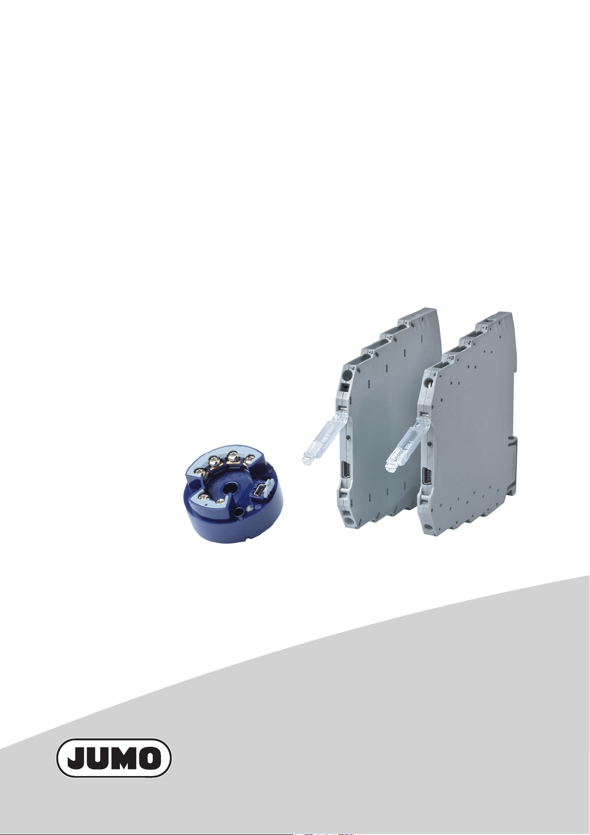
JUMO dTRANS T05
Programmierbarer Messumformer
Programmable Transmitter
Convertisseur de mesure
B 707050.0
Betriebsanleitung
Operating Manual
Notice de mise en service
2012-08-13/00576951
Page 2

Page 3
JUMO dTRANS T05
Programmierbarer Messumformer
in Zweidrahttechnik
B 707050.0
Betriebsanleitung
2012-08-13/00576951
Page 4

Page 5

Inhalt
1 Einleitung . . . . . . . . . . . . . . . . . . . . . . . . . . . . . . . . . . . . . . . . . . . . . . . . . . . . . . . .5
1.1 Sicherheitshinweise . . . . . . . . . . . . . . . . . . . . . . . . . . . . . . . . . . . . . . . . . . . . . . . . . . . . . . . . . . . . 5
1.2 Kurzbeschreibung . . . . . . . . . . . . . . . . . . . . . . . . . . . . . . . . . . . . . . . . . . . . . . . . . . . . . . . . . . . . . 6
1.3 Blockschaltbild . . . . . . . . . . . . . . . . . . . . . . . . . . . . . . . . . . . . . . . . . . . . . . . . . . . . . . . . . . . . . . . . 6
1.4 Abmessungen . . . . . . . . . . . . . . . . . . . . . . . . . . . . . . . . . . . . . . . . . . . . . . . . . . . . . . . . . . . . . . . . 7
1.4.1 Messumformer dTRANS T05 B (707050) . . . . . . . . . . . . . . . . . . . . . . . . . . . . . . . . . . . . . . . . . . . 7
1.4.2 Messumformer dTRANS T05 T (707051) . . . . . . . . . . . . . . . . . . . . . . . . . . . . . . . . . . . . . . . . . . . 7
2 Geräteausführung identifizieren . . . . . . . . . . . . . . . . . . . . . . . . . . . . . . . . . . . . .9
2.1 Typenschild . . . . . . . . . . . . . . . . . . . . . . . . . . . . . . . . . . . . . . . . . . . . . . . . . . . . . . . . . . . . . . . . . . 9
2.2 Bestellangaben . . . . . . . . . . . . . . . . . . . . . . . . . . . . . . . . . . . . . . . . . . . . . . . . . . . . . . . . . . . . . . 10
2.3 Lieferumfang . . . . . . . . . . . . . . . . . . . . . . . . . . . . . . . . . . . . . . . . . . . . . . . . . . . . . . . . . . . . . . . . 10
2.4 Zubehör . . . . . . . . . . . . . . . . . . . . . . . . . . . . . . . . . . . . . . . . . . . . . . . . . . . . . . . . . . . . . . . . . . . . 10
3 Montage . . . . . . . . . . . . . . . . . . . . . . . . . . . . . . . . . . . . . . . . . . . . . . . . . . . . . . . .11
3.1 Montage des dTRANS T05 B . . . . . . . . . . . . . . . . . . . . . . . . . . . . . . . . . . . . . . . . . . . . . . . . . . . 11
3.2 Montage/Demontage des dTRANS T05 T . . . . . . . . . . . . . . . . . . . . . . . . . . . . . . . . . . . . . . . . . 12
3.2.1 Anschluss der Leiter bei dTRANS T05 T mit Schraubklemmen . . . . . . . . . . . . . . . . . . . . . . . . . 12
3.2.2 Anschluss der Leiter bei dTRANS T05 T mit Federzugklemmen . . . . . . . . . . . . . . . . . . . . . . . . 13
3.2.3 Öffnen des Klappdeckels . . . . . . . . . . . . . . . . . . . . . . . . . . . . . . . . . . . . . . . . . . . . . . . . . . . . . . 13
3.2.4 Hutschienenmontage . . . . . . . . . . . . . . . . . . . . . . . . . . . . . . . . . . . . . . . . . . . . . . . . . . . . . . . . . 14
4 Elektrischer Anschluss . . . . . . . . . . . . . . . . . . . . . . . . . . . . . . . . . . . . . . . . . . . .15
4.1 Sicherheitshinweise . . . . . . . . . . . . . . . . . . . . . . . . . . . . . . . . . . . . . . . . . . . . . . . . . . . . . . . . . . . 15
4.2 Anschlussbelegung und Abmessungen (mm) dTRANS T05 B . . . . . . . . . . . . . . . . . . . . . . . . . . 15
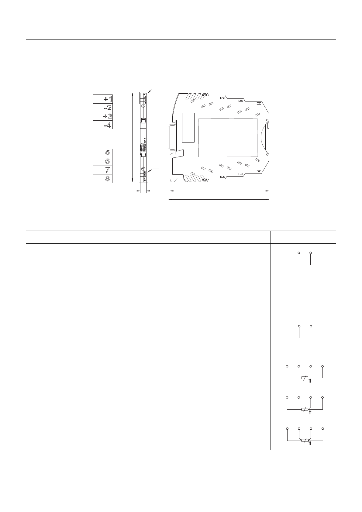
4.3 Anschlussbelegung und Abmessungen (mm) dTRANS T05 T . . . . . . . . . . . . . . . . . . . . . . . . . . 17
4.4 PC-Schnittstelle für dTRANS T05 Typ B und T . . . . . . . . . . . . . . . . . . . . . . . . . . . . . . . . . . . . . . 18
5 Konfiguration . . . . . . . . . . . . . . . . . . . . . . . . . . . . . . . . . . . . . . . . . . . . . . . . . . . .19
5.1 Verbindung zwischen PC und Messumformer herstellen . . . . . . . . . . . . . . . . . . . . . . . . . . . . . . 19
5.2 Setup-Programm . . . . . . . . . . . . . . . . . . . . . . . . . . . . . . . . . . . . . . . . . . . . . . . . . . . . . . . . . . . . . 20
5.3 Arbeiten mit dem Setup-Programm . . . . . . . . . . . . . . . . . . . . . . . . . . . . . . . . . . . . . . . . . . . . . . . 21
5.3.1 Aufbau der Kommunikation mit dem Messumformer . . . . . . . . . . . . . . . . . . . . . . . . . . . . . . . . . 21
5.3.2 Kundenspezifische Linearisierung . . . . . . . . . . . . . . . . . . . . . . . . . . . . . . . . . . . . . . . . . . . . . . . . 23
5.3.3 Schleppzeigerfunktion . . . . . . . . . . . . . . . . . . . . . . . . . . . . . . . . . . . . . . . . . . . . . . . . . . . . . . . . . 24
5.3.4 Betriebsstundenzähler . . . . . . . . . . . . . . . . . . . . . . . . . . . . . . . . . . . . . . . . . . . . . . . . . . . . . . . . . 25
5.3.5 Aktuellen Messwert/Gerätestatus anzeigen . . . . . . . . . . . . . . . . . . . . . . . . . . . . . . . . . . . . . . . . 25
6 Anhang . . . . . . . . . . . . . . . . . . . . . . . . . . . . . . . . . . . . . . . . . . . . . . . . . . . . . . . . .27
6.1 Technische Daten . . . . . . . . . . . . . . . . . . . . . . . . . . . . . . . . . . . . . . . . . . . . . . . . . . . . . . . . . . . . 27
6.1.1 LED-Signalisierung . . . . . . . . . . . . . . . . . . . . . . . . . . . . . . . . . . . . . . . . . . . . . . . . . . . . . . . . . . . 27
3
Page 6

Inhalt
6.1.2 Analogeingang . . . . . . . . . . . . . . . . . . . . . . . . . . . . . . . . . . . . . . . . . . . . . . . . . . . . . . . . . . . . . . 27
6.1.3 Messkreisüberwachung . . . . . . . . . . . . . . . . . . . . . . . . . . . . . . . . . . . . . . . . . . . . . . . . . . . . . . . . 30
6.1.4 Ausgang . . . . . . . . . . . . . . . . . . . . . . . . . . . . . . . . . . . . . . . . . . . . . . . . . . . . . . . . . . . . . . . . . . . 31
6.1.5 Kundenspezifische Linearisierung . . . . . . . . . . . . . . . . . . . . . . . . . . . . . . . . . . . . . . . . . . . . . . . . 31
6.1.6 Spannungsversorgung . . . . . . . . . . . . . . . . . . . . . . . . . . . . . . . . . . . . . . . . . . . . . . . . . . . . . . . . 32
6.1.7 Umwelteinflüsse . . . . . . . . . . . . . . . . . . . . . . . . . . . . . . . . . . . . . . . . . . . . . . . . . . . . . . . . . . . . . 32
6.1.8 Gehäuse . . . . . . . . . . . . . . . . . . . . . . . . . . . . . . . . . . . . . . . . . . . . . . . . . . . . . . . . . . . . . . . . . . . 33
4
Page 7
1.1 Sicherheitshinweise
Allgemein
Diese Anleitung enthält Hinweise, die Sie zu Ihrer eigenen Sicherheit sowie zur Vermeidung
von Sachschäden beachten müssen. Diese Hinweise sind durch Zeichen unterstützt und werden in dieser Anleitung wie gezeigt verwendet.
Lesen Sie diese Anleitung, bevor Sie das Gerät in Betrieb nehmen. Bewahren Sie die Anleitung
an einem für alle Benutzer jederzeit zugänglichen Platz auf.
Sollten bei der Inbetriebnahme Schwierigkeiten auftreten, bitten wir Sie, keine Manipulationen
vorzunehmen, die Ihren Gewährleistungsanspruch gefährden können!
Warnende Zeichen
VORSICHT!
Dieses Zeichen in Verbindung mit dem Signalwort weist darauf hin, dass ein Sachschaden
oder ein Datenverlust auftritt, wenn die entsprechenden Vorsichtsmaßnahmen nicht getrof-
fen werden.
Hinweisende Zeichen
1 Einleitung
HINWEIS!
Dieses Zeichen weist auf eine wichtige Information über das Produkt oder dessen Handhabung oder Zusatznutzen hin.
5
Page 8
1 Einleitung
Messumformer
707050
707051
: 4 ... 20 mA
: 4 ... 20 mA
0 ... 10 V
Ausgangssignale:
Spannungsversorgung:
Setup
USB-Schnittstelle:
Spannung
+
-
Widerstandsthermometer
Widerstandspotenziometer/WFG
Eingangssignale:
Thermoelement
DC 11 ... 35 V
Widerstand/Poti
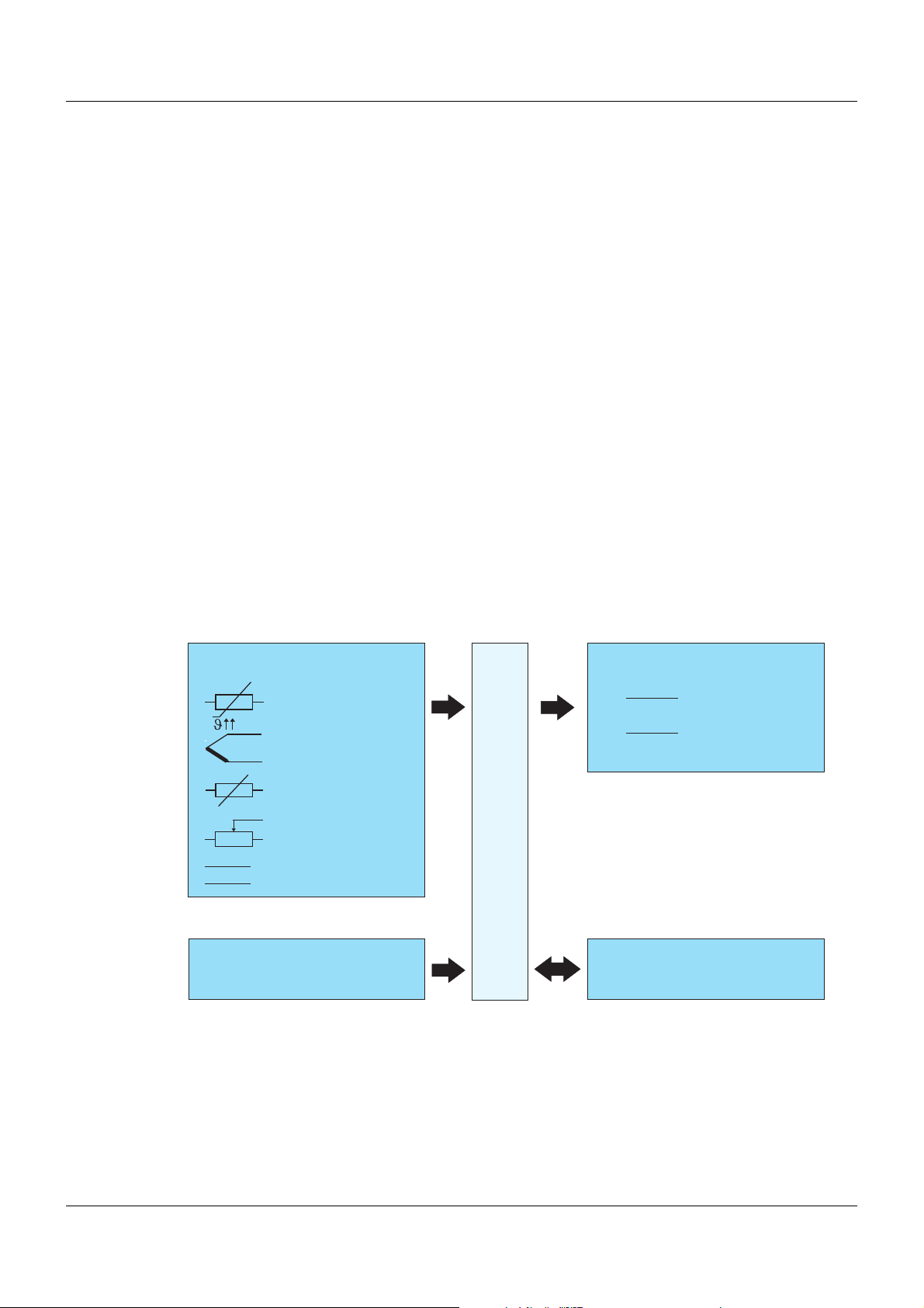
1.2 Kurzbeschreibung
Die Messumformer erfassen Sensorsignale von Widerstandsthermometern, Thermoelementen, Widerstandspotenziometern/WFG oder Widerständen/Potis. Bei Einsatz eines Widerstands/Potis oder Widerstandsthermometers kann der eingangsseitige Sensoranschluss in
Zwei-, Drei- oder Vierleiterschaltung erfolgen. Spannungssignale im Bereich von -100 ... +1100
mV können ebenfalls erfasst werden. Je nach Wahl des Messeingangs stehen die Linearisierungsvarianten linear, temperaturlinear sowie die Möglichkeit einer komfortabel konfigurierbaren kundenspezifischen Linearisierung zur Verfügung.
Als Ausgangssignal liefert der Typ 707050 4 ... 20 mA. Der Typ 707051 bietet als Ausgangssignal 4 ... 20 mA oder 0 ... 10 V. Der Messeingang und das Ausgangssignal sind voneinander
galvanisch getrennt. Bei beiden Typen ist eine Reversion des Ausgangssignals möglich.
Die Konfiguration des Messumformers hinsichtlich Fühlerart, Anschlusstechnik des Fühlers,
Messbereich (frei einstellbar) und Linearisierung erfolgt mit Hilfe eines Setup-Programms am
PC. Die Verbindung mit dem PC wird über eine USB-Schnittstelle, welche keine zusätzliche
Hilfsspannung benötigt, hergestellt. Über die USB-Schnittstelle kann der vom Messumformer
erfasste Min.-/Max.-Prozesswert, die Min.-/Max.-Betriebstemperatur ausgelesen und die Sensorverdrahtung online überprüft werden.
Der Betriebszustand des Messumformers wird über eine zweifarbige Kontroll-LED (rot/grün) signalisiert. Im störungsfreien Betrieb leuchtet diese grün. Tritt eine Störung auf, wie z. B. Fühlerbruch, wird dies durch die entsprechende LED-Signalisierung angezeigt.
1.3 Blockschaltbild
6
Page 9
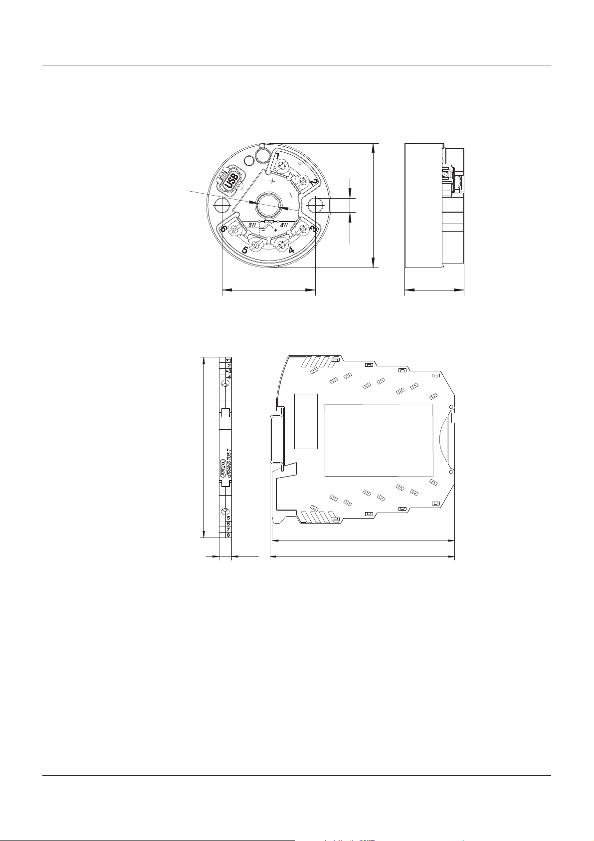
1.4 Abmessungen
5Ø
44Ø
7Ø
33 21
101.2
102.5
6.3
93.1
1.4.1 Messumformer dTRANS T05 B (707050)
1.4.2 Messumformer dTRANS T05 T (707051)
1 Einleitung
Diese Darstellung zeigt den Typ 707051 montiert auf einer Hutschiene TH 35-7,5. Die Angaben zur
Bemaßung sind nur bei Montage auf dieser Hutschiene gültig und verändern sich entsprechend,
wenn eine Hutschiene TH 35-15 eingesetzt wird.
7
Page 10

1 Einleitung
8
Page 11
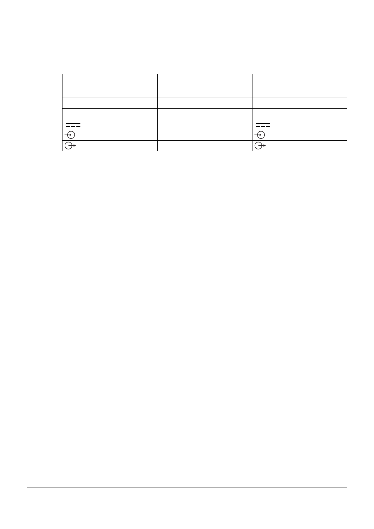
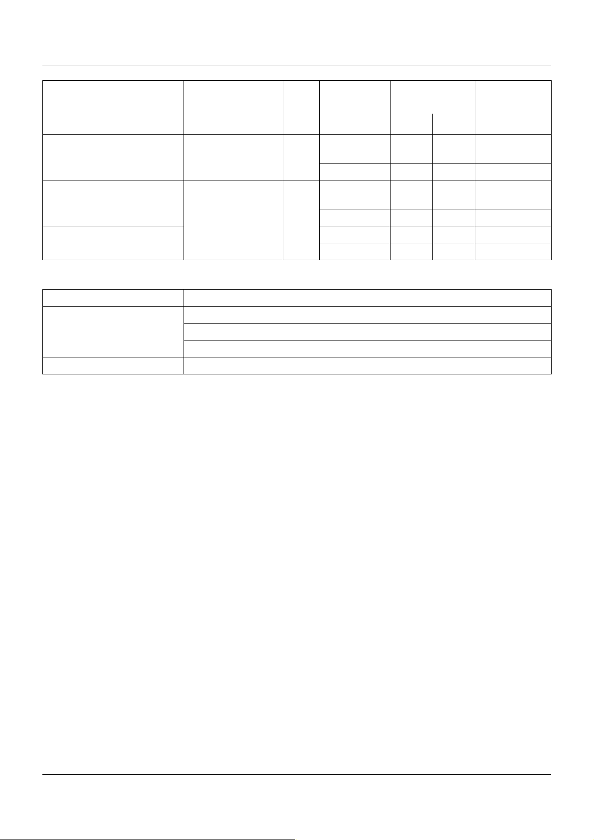
2.1 Typenschild
Typenschildangabe Beschreibung Beispiel
Typ Gerätetyp 707050/8-06
TN Teile-Nr. 00582219
F-Nr Fabrikations-Nummer 0167938001012140001
Gerätetyp (Typ)
Vergleichen Sie die Angaben auf dem jeweiligen Typenschild mit Ihren Bestellunterlagen. Mit
dem Typenschlüssel in Kapitel 2.2 „Bestellangaben“, Seite 10, können Sie die gelieferte Geräteausführung identifizieren.
Teile-Nr. (TN)
Die Teile-Nr. kennzeichnet einen Artikel im Katalog eindeutig. Sie ist wichtig für die Kommunikation zwischen Kunden und Verkauf.
2 Geräteausführung identifizieren
Spannungsversorgung DC 11 ... 35 V
Symbol für Eingang programmierbar
Symbol für Ausgang 4 ... 20 mA
Fabrikations-Nummer (F-Nr)
Der Fabrikations-Nummer kann u. a. das Produktionsdatum (Jahr/Woche) und die Versionsnummer der Hardware entnommen werden.
Produktionsdatum
Beispiel: F-Nr = 0167938001012140001
Es handelt sich hierbei um die Zeichen an den Stellen 12, 13, 14, 15 (von links).
Das Gerät wurde in der 14. Woche 2012 produziert.
9
Page 12
2 Geräteausführung identifizieren
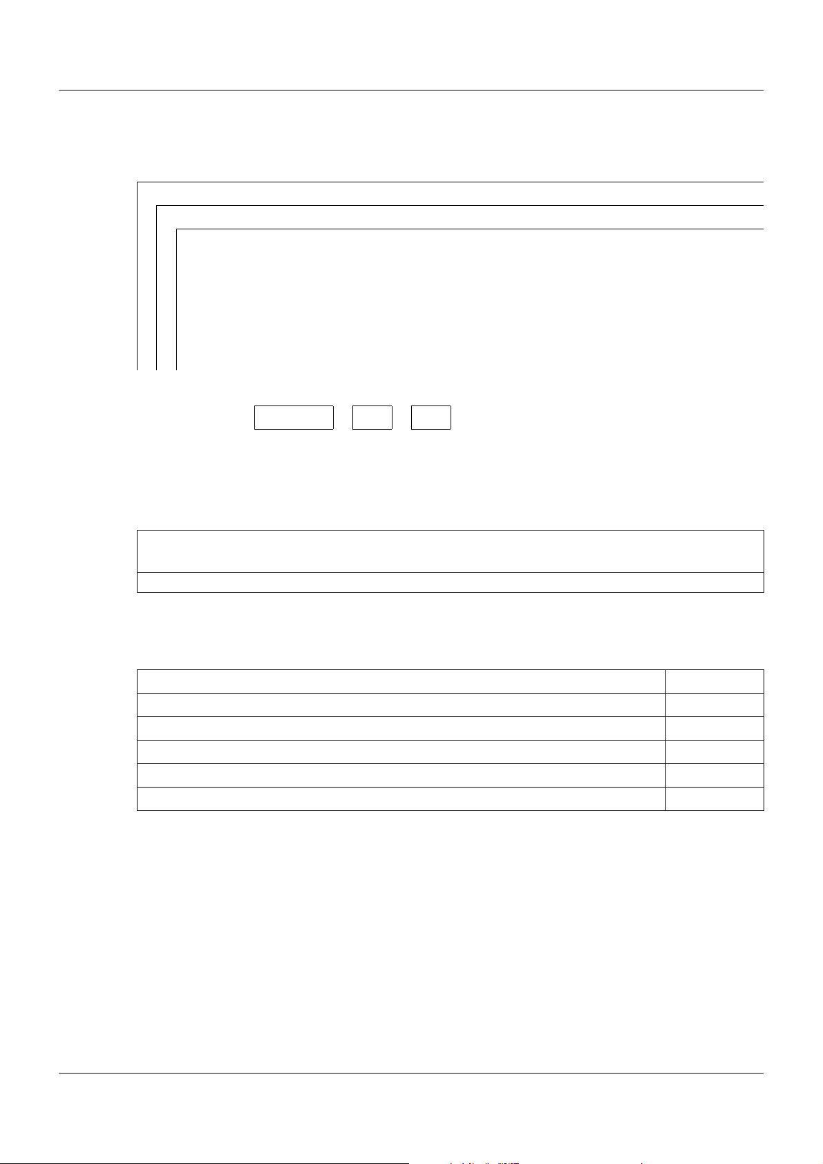
2.2 Bestellangaben
(1) Grundtyp
707050 dTRANS T05 B - Zweidraht-Messumformer
707051 dTRANS T05 T - Zweidraht-Messumformer im Tragschienengehäuse
(2) Konfiguration
xx 8 Werkseitig eingestellt (0 ... 100 °C, Pt100 Dreileiterschaltung, 4 ... 20 mA)
xx 9 Kundenspezifisch eingestellt
(3) Elektrische Anschlussart
xx 06 Schraubklemmen
x 07 Federzugklemmen
(1) (2) (3)
Bestellschlüssel /-
Bestellbeispiel 707050 / 8 - 06
2.3 Lieferumfang
1 Messumformer in der bestellten Ausführung
Bei Typ 707050: inkl. Befestigungsmaterial (2 Schrauben, 2 Druckfedern und 2 Sicherungsscheiben)
1 Betriebsanleitung B 707050.0
2.4 Zubehör
Artikel Teile-Nr.
Setup-Programm auf CD-ROM, mehrsprachig 00574959
Betriebsanleitung B 707050.0 00576951
USB-Kabel A-Stecker auf mini B-Stecker, Länge 3 m 00506252
Schraubbarer Endhalter für Tragschiene 00528648
Befestigungselement zur Montage von Typ 707050 auf Tragschiene 00352463
10
Page 13
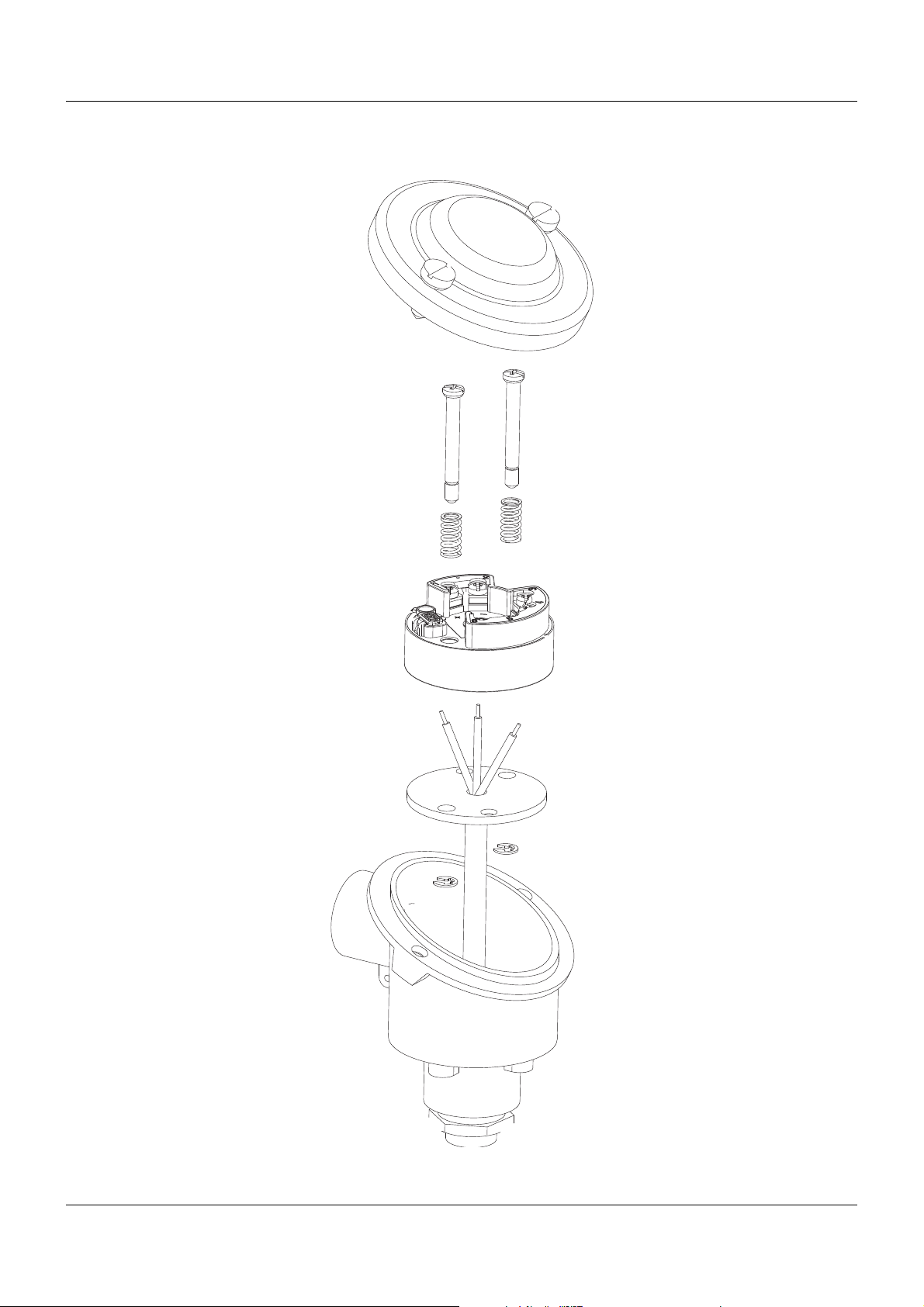
3.1 Montage des dTRANS T05 B
3 Montage
11
Page 14
3 Montage
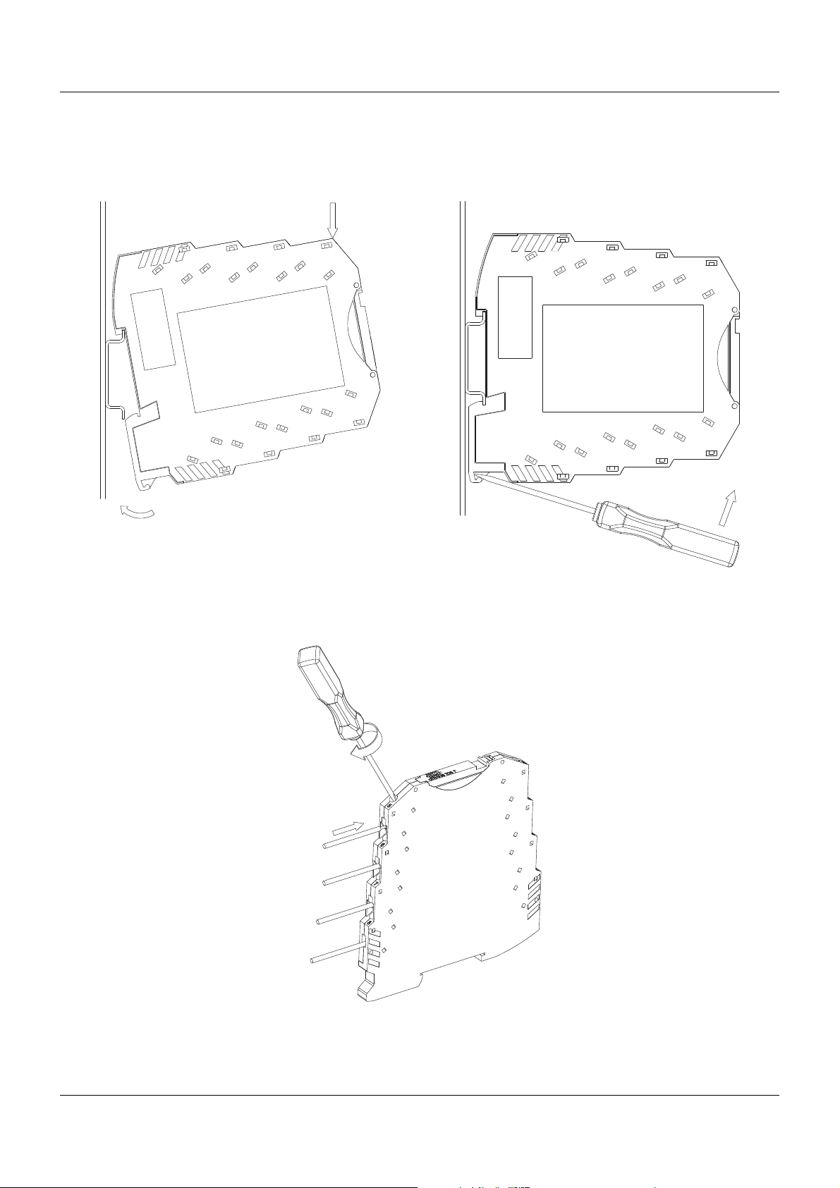
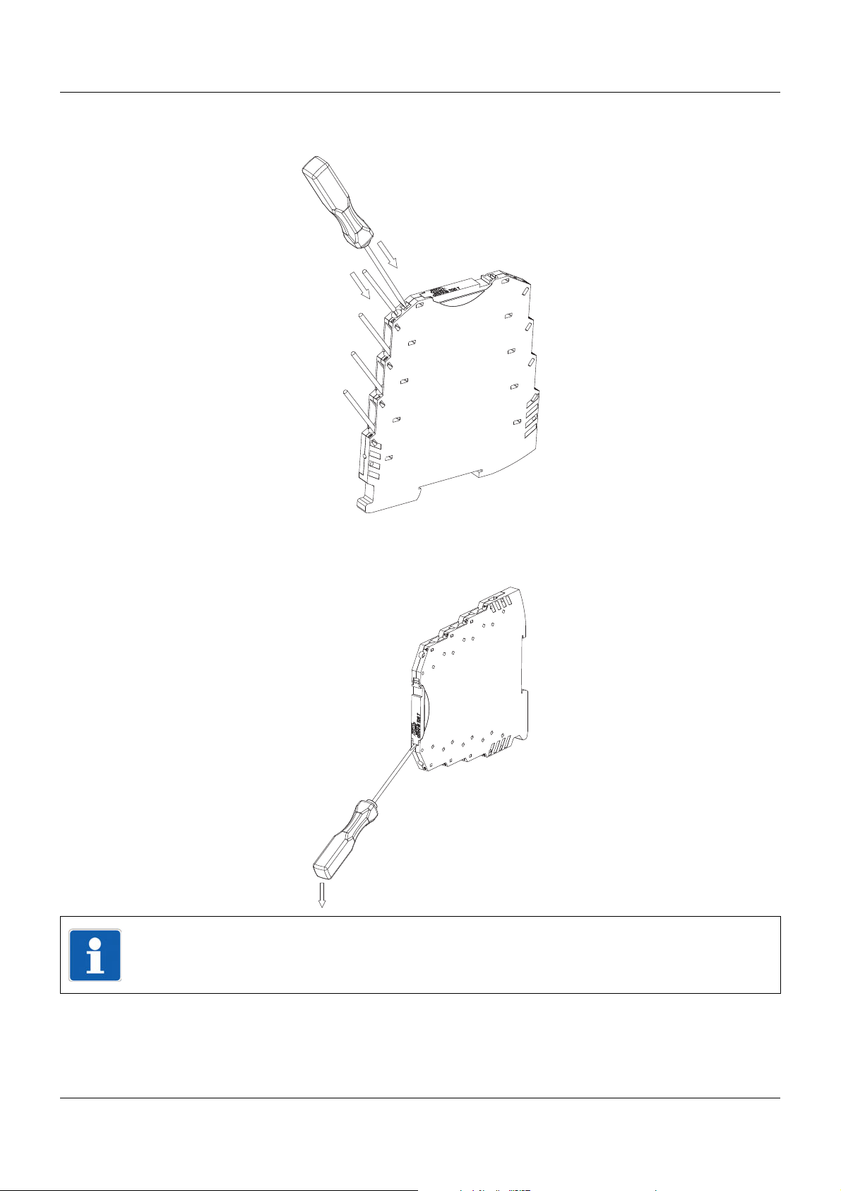
3.2 Montage/Demontage des dTRANS T05 T
Montage Demontage
3.2.1 Anschluss der Leiter bei dTRANS T05 T mit Schraubklemmen
12
Page 15
3 Montage
3.2.2 Anschluss der Leiter bei dTRANS T05 T mit Federzugklemmen
3.2.3 Öffnen des Klappdeckels
HINWEIS!
Nach dem Beenden der Konfiguration des Messumformers über den USB-Port ist der Klappdeckel wieder zu schließen.
13
Page 16
3 Montage
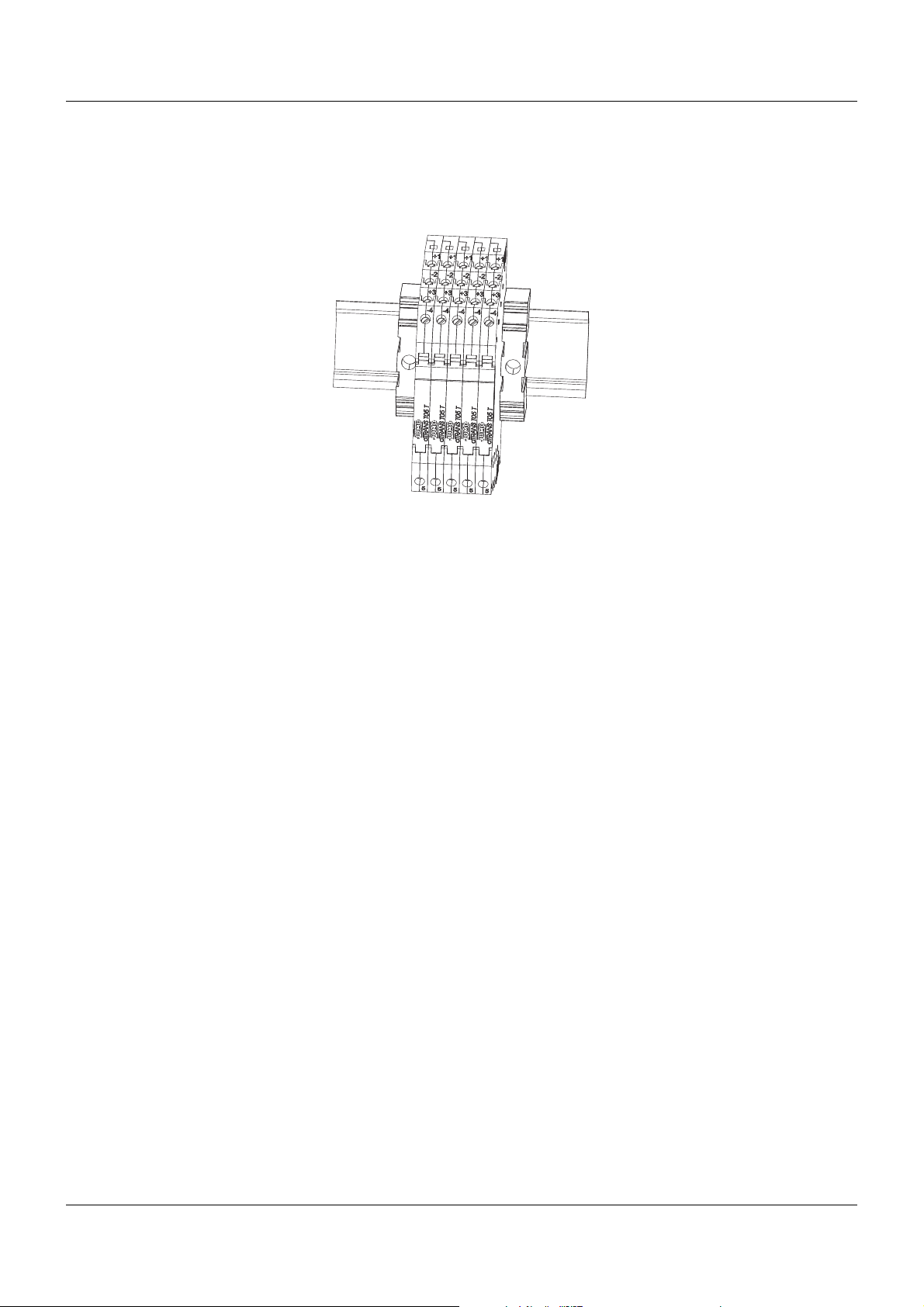
3.2.4 Hutschienenmontage
Es ist darauf zu achten, dass das Gerät nicht auf der Hutschiene verrutschen kann. Zu diesem
Zweck sollten neben den äußeren Geräten auf der Hutschiene Endhalter für Tragschienen angebracht werden. Diese sind als Zubehör erhältlich.
14
Page 17
4 Elektrischer Anschluss
5Ø
44Ø
7Ø
33 21
2
1
+
–
4.1 Sicherheitshinweise
• Der elektrische Anschluss darf ausschließlich von Fachpersonal durchgeführt werden.
• Während Montage, Anschluss und Betrieb des Messumformers ist darauf zu achten, dass
keine elektrostatische Aufladung auftreten kann.
• Der Messumformer ist nicht für die Installation und Anwendung in explosionsgefährdeten
Bereichen geeignet.
• Den Messumformer keinen magnetischen oder elektrischen Feldern (z. B. durch Transformatoren, Funksprechgeräte oder elektrostatische Entladungen) aussetzen.
• Ein vom Anschlussplan abweichender elektrischer Anschluss kann zur Zerstörung des
Messumformers führen.
• Der Messumformer ist für den Einsatz in SELV- oder PELV-Stromkreisen nach Schutzklasse 3 geeignet. Das Gehäuse realisiert zu benachbarten Geräten eine Basisisolierung bis
50 V.
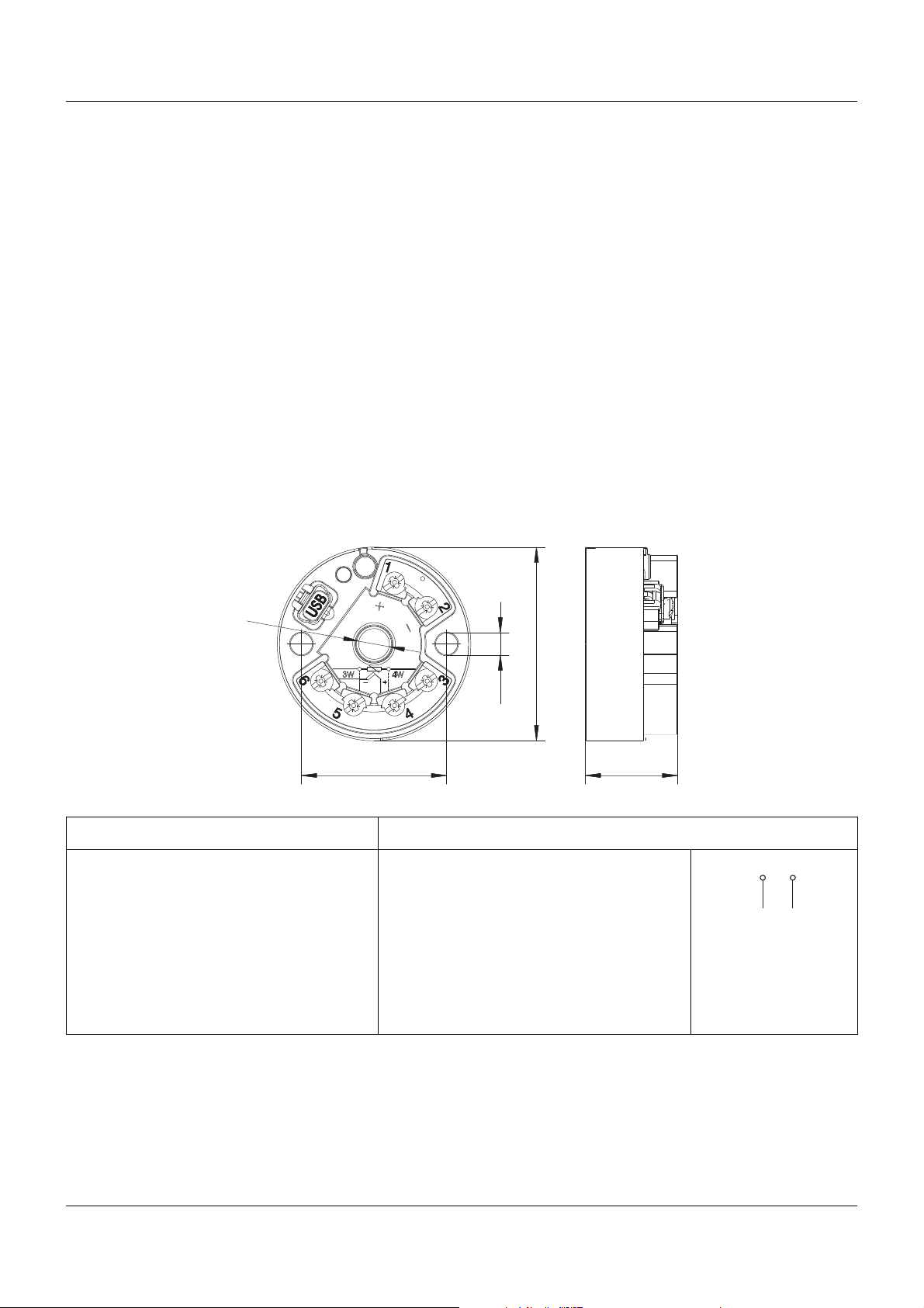
4.2 Anschlussbelegung und Abmessungen (mm) dTRANS T05 B
Anschluss für Anschlussbelegung
Spannungsversorgung
Typ 707050 R
DC 11 ... 35 V
Stromausgang R
4...20mA U
=(Ub-11V)/22mA
B
= Bürdenwiderstand
B
= Spannungsversorgung
b
15
Page 18
4 Elektrischer Anschluss
4
5
6
3
J
4
5
6
3
J
4
5
6
3
J
+
–
4
5
6
3
4
5
6
3
4
5
6
3
4
5
6
3
E
S
A
4
5
6
3
+
4
5
6
3
–
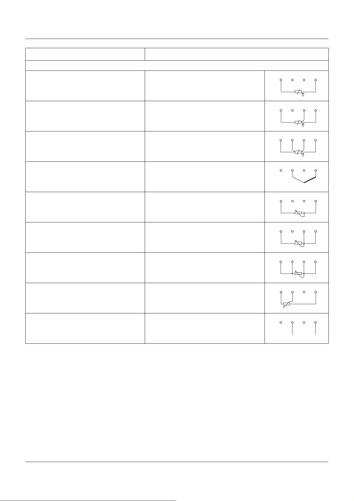
Anschluss für Anschlussbelegung
Analoge Eingänge
Widerstandsthermometer R
Zweileiterschaltung R
Widerstandsthermometer R
Dreileiterschaltung (3W) R
Widerstandsthermometer R
Vierleiterschaltung (4W) R
Thermoelement
Widerstand/Poti R
Zweileiterschaltung R
Widerstand/Poti R
Dreileiterschaltung (3W) R
11
L
= Leitungswiderstand je Leiter
L
11
L
= Leitungswiderstand je Leiter
L
11
L
= Leitungswiderstand je Leiter
L
11
L
= Leitungswiderstand je Leiter
L
11
L
= Leitungswiderstand je Leiter
L
Widerstand/Poti R
Vierleiterschaltung (4W) R
11
L
= Leitungswiderstand je Leiter
L
Widerstandspotenziometer/WFG E = Ende
S = Schleifer
A=Anfang
Spannung 0 ... 1 V
16
Page 19
4 Elektrischer Anschluss
101.2
102.5
6.2
93.1
A
B
A 5:1
B 5:1
2
1
+
–
4
3
+
–
6
7
8
5
J
J
6
7
8
5
J
6
7
8
5
4.3 Anschlussbelegung und Abmessungen (mm) dTRANS T05 T
Diese Darstellung zeigt den Typ 707051 montiert auf einer Hutschiene TH 35-7,5. Die Angaben zur Bemaßung
sind nur bei Montage auf dieser Hutschiene gültig und verändern sich entsprechend, wenn eine Hutschiene TH 3515 eingesetzt wird.
Anschluss für Anschlussbelegung
Spannungsversorgung
Typ 707051 R
=(Ub-11V)/22mA
B
DC 11 ... 35 V
Stromausgang R
4...20mA U
= Bürdenwiderstand
B
= Spannungsversorgung
b
Spannungsausgang
0...10V
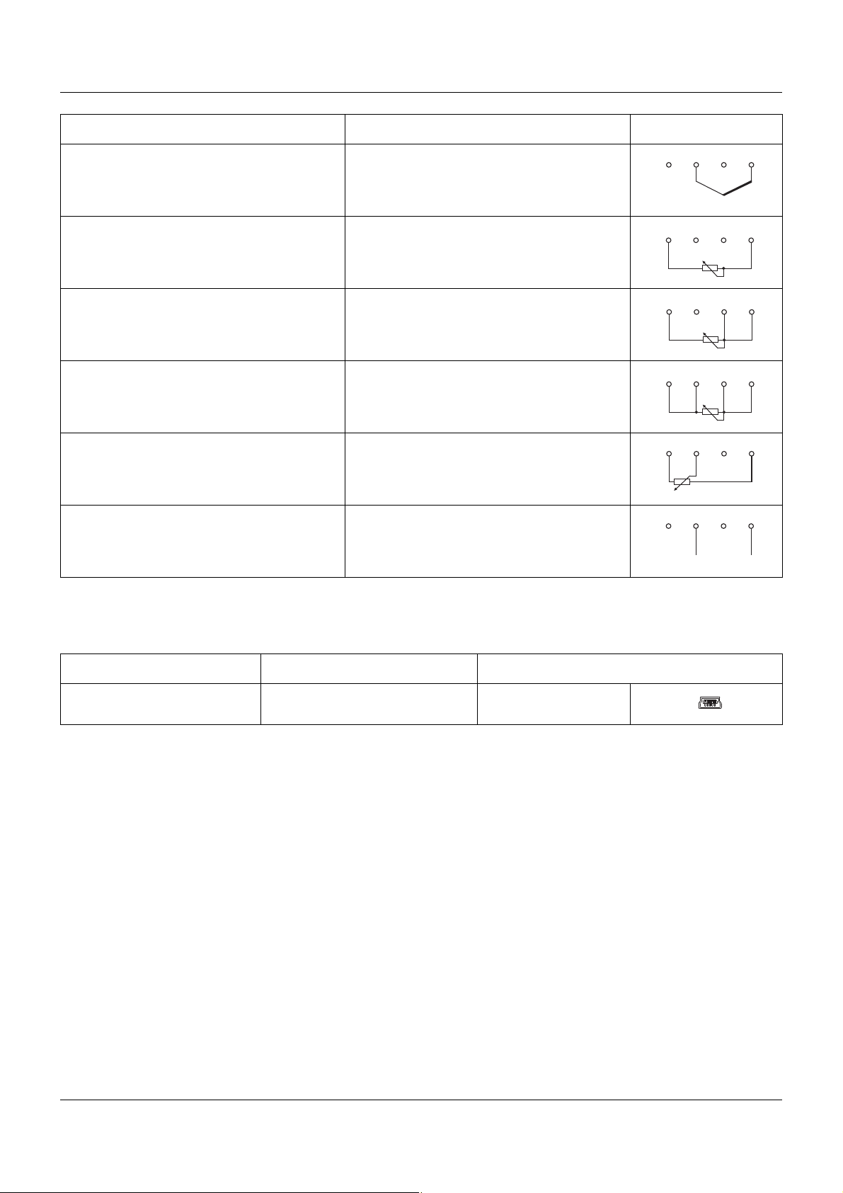
Analoge Eingänge
Widerstandsthermometer R
Zweileiterschaltung R
Widerstandsthermometer R
Dreileiterschaltung (3W) R
11
L
= Leitungswiderstand je Leiter
L
11
L
= Leitungswiderstand je Leiter
L
Widerstandsthermometer R
Vierleiterschaltung (4W) R
11
L
= Leitungswiderstand je Leiter
L
17
Page 20
4 Elektrischer Anschluss
6
7
8
5
+
–
6
7
8
5
6
7
8
5
6
7
8
5
6
7
8
5
E
S
A
6
7
8
5
+
–
Anschluss für Anschlussbelegung
Thermoelement
Widerstand/Poti R
Zweileiterschaltung R
Widerstand/Poti R
Dreileiterschaltung (3W) R
Widerstand/Poti R
Vierleiterschaltung (4W) R
11
L
= Leitungswiderstand je Leiter
L
11
L
= Leitungswiderstand je Leiter
L
11
L
= Leitungswiderstand je Leiter
L
Widerstandspotenziometer/WFG E = Ende
S = Schleifer
A=Anfang
Spannung 0 ... 1 V
4.4 PC-Schnittstelle für dTRANS T05 Typ B und T
Anschluss für Typ Anschlussbelegung
USB-Verbindung mit PC USB-Schnittstelle 2.0 (Mini-B;
Standard (5-polig)
Full-Speed)
18
Page 21
5 Konfiguration
(1)
(2)
(3)
(4)
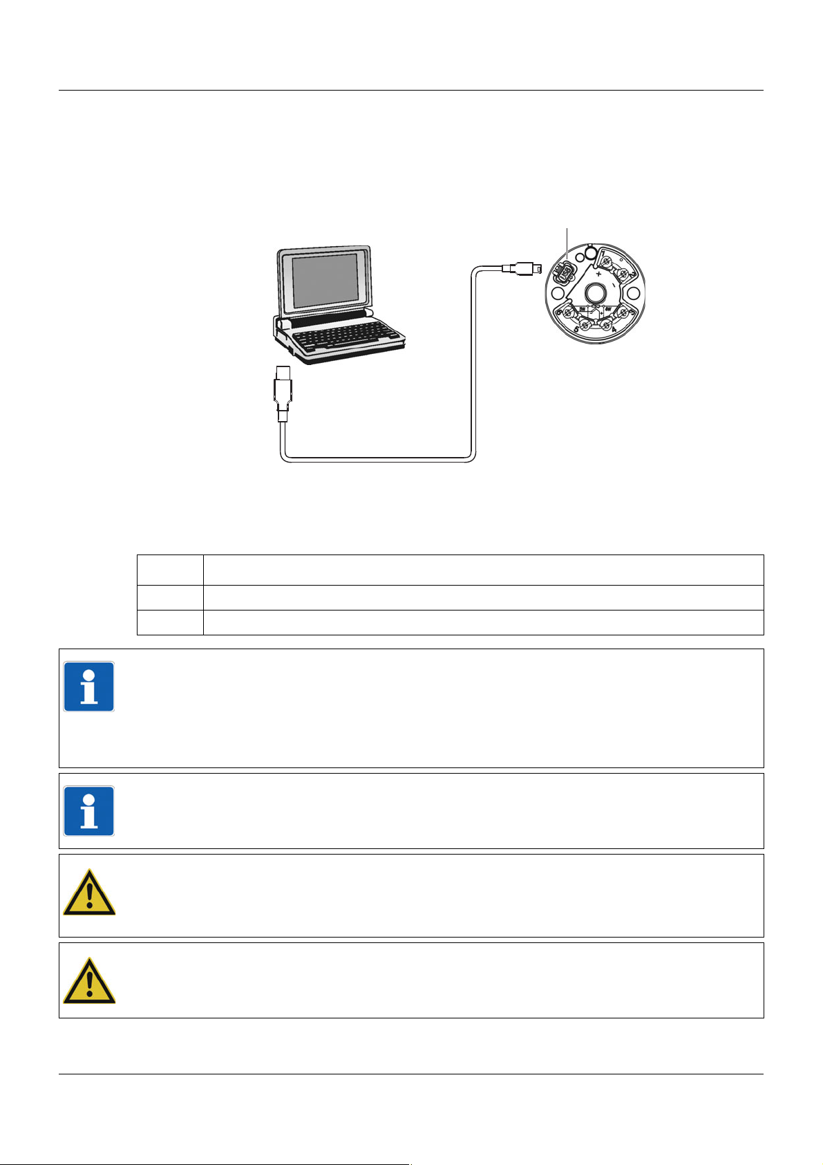
5.1 Verbindung zwischen PC und Messumformer herstellen
Die Verbindung zwischen Messumformer und PC wird über ein USB-Kabel hergestellt.
Die Verbindung zwischen PC und Messumformer am Beispiel des Typs 707050
(1) Laptop/PC (3) Mini USB-Stecker Typ B
(2) USB-Stecker (4) USB-Buchse für USB-Stecker Typ B
Für das Setup über USB stellen Sie folgende Verbindungen her:
Schritt Tätigkeit
1 USB-Stecker (2) der USB-Leitung in den Laptop/PC (1) stecken.
2 Mini-USB Stecker (3) der USB-Leitung in die Buchse des Messumformers (4) stecken.
HINWEIS!
Ist die Verbindung von PC und Messumformer über USB hergestellt, und der Messumformer
ist ausgangsseitig nicht verdrahtet, erfolgt die Energieversorgung des Messumformers über
die USB-Schnittstelle des PC. Der Stromausgang (bei dTRANS T05 T auch die Spannungsausgang) sowie die zweifarbige LED sind dann außer Betrieb.
Im Betrieb des Messumformers ohne USB-Verbindung ist die USB-Schnittstelle deaktiviert.
HINWEIS!
Zur Gewährleistung eines reibungslosen Betriebs des Messumformers an einer USB-Schnittstelle muss diese den Festlegungen der USB-Spezifikation 2.0 entsprechen.
VORSICHT!
Eine USB-Verbindung bei geerdetem Sensor muss vermieden werden, wenn auch die Masse
des PC geerdet ist (z. B. bei Desktop-PC). Der Messeingang und die USB-Schnittstelle sind
nicht galvanisch getrennt.
VORSICHT!
Ein Kurzschluss zwischen USB-Masse und den Sensoranschlussklemmen ist zu vermeiden.
19
Page 22
5 Konfiguration
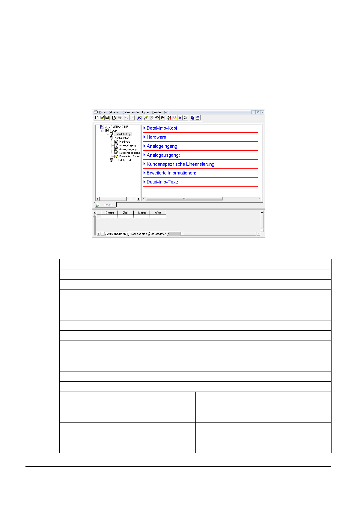
5.2 Setup-Programm
Mit dem Setup-Programm wird der Messumformer am PC konfiguriert. Die Verbindung zwischen Messumformer und PC wird über ein USB-Kabel hergestellt. Bei der Schnittstelle des
Messumformers handelt es sich um einen USB-Port des Typs Mini-B. Dieser unterstützt den
Standard 2.0 „Full-Speed“. Nach der Konfiguration des Messumformers ist darauf zu achten,
dass sich der Klappdeckel wieder auf der USB-Schnittstelle des Messumformers befindet.
Konfigurierbare Parameter
Sensortyp
Anschlussart 2-/3- oder 4-Leiterschaltung für Widerstandsthermometer oder Widerstand/Poti
Linearisierung
Kundenspezifische Linearisierung
Sensorfaktor für Thermoelement/Widerstandsthermometer
Leitungswiderstand bei 2-Leiterschaltung
Externe oder interne Vergleichsstelle bei Thermoelement
Skalierung
Digitales Filter
Offset
Einheit
Verhalten bei Fühlerbruch/-kurzschluss
Ausgangssignal steigend oder fallend (Reversion)
Ausgangsfunktionen Strom 4 ... 20 mA
Typ 705050 und Typ 705051 4 ... 20 mA skalierbar (Anfang/Ende)
Ausgangsfunktionen Spannung 0 ... 10 V
Nur Typ 705051 0 ... 10 V skalierbar (Anfang/Ende)
Konstantstromquelle
20
Konstantspannungsquelle
Page 23

5 Konfiguration
TAG-Nummer (10-stellig) und Beschreibung (20-stellig)
Installationsdatum
Versions-, Prozess- und Gerätedaten des Messumformers lassen sich anzeigen
Hardware- und Software-Voraussetzungen
Für den Betrieb und die Installation des Setup-Programms müssen folgende Hardware- und
Software-Voraussetzungen erfüllt sein:
Microsofta Windowsa XP, Vista, Windows 7 32 Bit/64 Bit
1 GByte Arbeitsspeicher
200 MB freier Festplattenspeicher
1 USB Schnittstelle
a
Microsoft und Windows sind eingetragene Warenzeichen der Microsoft Corporation
5.3 Arbeiten mit dem Setup-Programm
5.3.1 Aufbau der Kommunikation mit dem Messumformer
Um mit dem Setup-Programm eine Konfiguration auf den Messumformer zu übertragen oder
die Verbindung herzustellen, um Gerätedaten abfragen zu können, muss der richtige Messumformertyp im Setup-Programm ausgewählt werden.
Geräteassistent mit automatischer Erkennung der angeschlossenen Hardware
Schritt Tätigkeit
1 Messumformer mit USB-Kabel verbinden.
2 Setup-Programm starten.
3 Im Navigationsfenster Doppelklick auf S
4 Im Geräteassistent A
5 Wenn der korrekte Typ angezeigt wird, auf F
6 Der Messumformer wird verbunden.
UTOMATISCHE ERKENNUNG wählen und auf WEITER klicken.
ETUP > KONFIGURATION > HARDWARE.
ERTIG STELLEN klicken.
➥ Geräte- und Prozessdaten können angezeigt werden und der Datentransfer ist möglich.
Dies kann über das Menü D
TRANSFER AUS GERÄT... oder die entsprechenden Buttons geschehen.
ATENTRANSFER > DATENTRANSFER ZUM GERÄT... bzw. DATEN-
Geräteassistent mit benutzerdefinierter Einstellung
Schritt Tätigkeit
1 Messumformer mit USB-Kabel verbinden.
2 Setup-Programm starten.
3 Im Navigationsfenster Doppelklick auf S
4 Im Geräteassistent B
ENUTZERDEFINIERTE EINSTELLUNG wählen und auf WEITER klicken.
ETUP > KONFIGURATION > HARDWARE.
21
Page 24

5 Konfiguration
Schritt Tätigkeit
5 Korrekten Messumformertyp wählen und auf WEITER klicken.
6 Wenn der korrekte Typ angezeigt wird, auf F
7 Der Messumformer wird verbunden.
➥ Geräte- und Prozessdaten können angezeigt werden und der Datentransfer ist möglich.
Dies kann über das Menü D
TRANSFER AUS GERÄT... oder die entsprechenden Buttons geschehen.
ATENTRANSFER > DATENTRANSFER ZUM GERÄT... bzw. DATEN-
Speichern/Nutzen einer bestehenden Konfiguration
Nachdem die Konfiguration eines Messumformers abgeschlossen ist, kann diese mit D
S
PEICHERN UNTER ... abgespeichert werden. In dieser Setup-Datei sind alle konfigurierten Pa-
rameter und Einstellungen gespeichert. Diese können so jederzeit abgerufen und verändert
werden, auch ohne dass ein Gerät angeschlossen ist.
Schritt Tätigkeit
1 Setup-Programm starten. Das zuletzt geöffnete Setup wird erneut geöffnet. Dieses nöti-
genfalls schließen.
2Über D
wird geladen.
3 Die Konfiguration kann auch ohne angeschlossenen Messumformer durchgeführt werden.
4 Um die Konfiguration auf einen Messumformer zu laden oder auszulesen, muss dieser
angeschlossen werden und die Verbindung über den Gerätemanager oder über D
TRANSFER > VERBINDUNG AUFBAUEN hergestellt werden.
ATEI > ÖFFNEN eine Setup-Datei auswählen und mit ÖFFNEN bestätigen. Die Datei
ERTIG STELLEN klicken.
ATEI >
ATEN-
➥ Geräte- und Prozessdaten können angezeigt werden und der Datentransfer ist möglich.
Dies kann über das Menü D
TRANSFER AUS GERÄT... oder die entsprechenden Buttons geschehen.
ATENTRANSFER > DATENTRANSFER ZUM GERÄT... bzw. DATEN-
22
Page 25
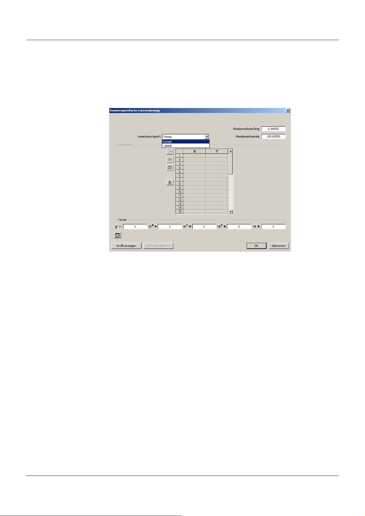
5.3.2 Kundenspezifische Linearisierung
Die Messumformer dTRANS T05 B und T bieten die Möglichkeit, Messwerte kundenspezifisch
zu linearisieren. Die entsprechende Maske zur Konfiguration ist in der Setup-Software entweder über das Menü E
unter S
ETUP > KONFIGURATION > KUNDENSPEZIFISCHE LINEARISIERUNG zu erreichen. Die Linea-
risierung erfolgt über eine Wertetabelle oder ein Polynom 4. Ordnung.
DITIEREN > KUNDENSPEZIFISCHE LINEARISIERUNG oder in der Baumstruktur
5 Konfiguration
Linearisierung auf Basis des Polynoms 4. Ordnung
Zur Linearisierung auf Basis des Polynoms 4. Ordnung muss im Auswahlfeld L
RUNGSART der Eintrag FORMEL gewählt werden. Die Koeffizienten des Polynoms können direkt
eingegeben werden und die Tabelle ist für Eingaben gesperrt. Mit einem Klick auf den G
ANZEIGEN
-Button wird die grafische Anzeige aktiviert.
Linearisierung auf Basis der Wertetabelle
Soll die Linearisierung anhand einer Tabelle mit Wertepaaren erfolgen, muss im Auswahlfeld
L
INEARISIERUNGSART der Eintrag TABELLE gewählt werden. Das Eintragen von Polynomkoeffi-
zienten ist nicht möglich. Die X- und Y-Werte können dann in die Tabelle eingetragen und mit
einem Klick auf den G
RAFIK ANZEIGEN-Button grafisch dargestellt werden.
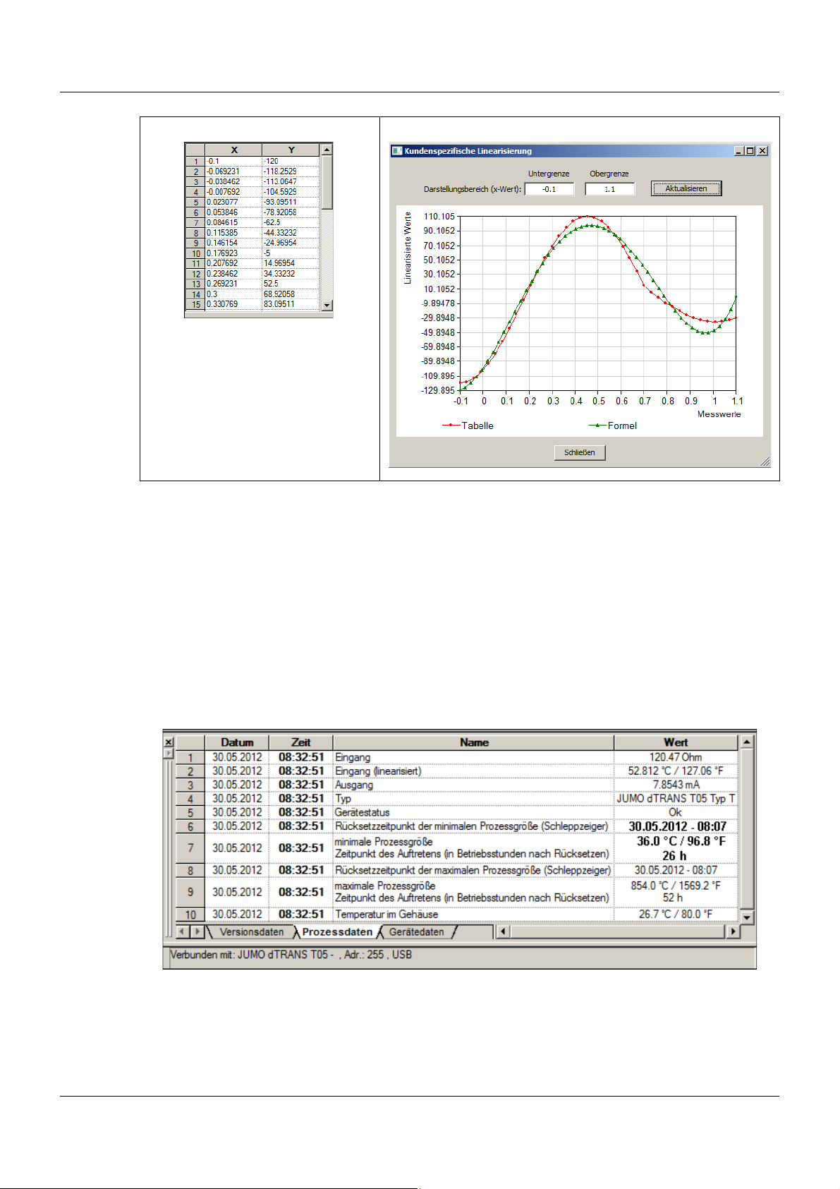
Linearisierung mit berechneten Polynomkoeffizienten
Werden mindestens zwei Wertepaare zur Linearisierung genutzt, bietet das Setup-Programm
die Möglichkeit, aus diesen die Polynomkoeffizienten zu berechnen. Die Linearisierung erfolgt
dann auf Basis des Polynoms. Dazu muss zuerst im Auswahlfeld der Eintrag T
werden. Sind die jeweiligen Wertepaare eingetragen, können die Polynomkoeffizienten mit einem Klick auf den f
ANZEIGEN
-Button wird die grafische Anzeige aktiviert. Die folgenden Bilder zeigen exempla-
-Button automatisch berechnet werden. Mit einem Klick auf den GRAFIK
x
risch eine Tabelle mit Wertepaaren sowie den Graf der Wertepaare mit überlagertem Graf des
Polynoms.
INEARISIE-
RAFIK
ABELLE gewählt
23
Page 26
5 Konfiguration
5.3.3 Schleppzeigerfunktion
Mit der Schleppzeigerfunktion erfolgt eine Registrierung der minimalen und maximalen Prozessgröße (z. B. Temperatur), die während des Betriebes des Messumformers am Sensor auftrat. Diese Werte können zurückgesetzt werden. Die Rücksetzzeitpunkte für die Schleppzeiger
sind im Gerät gespeichert und werden zusätzlich angezeigt. Neben den eigentlichen minimalen und maximalen Prozesswerten wird jeweils der Zeitpunkt des Auftretens, gemessen in Betriebsstunden seit dem Rücksetzzeitpunkt, angezeigt. Dadurch können Rückschlüsse auf
Besonderheiten der Anlage gezogen werden.
Um diese Daten einsehen zu können, muss im Setup-Programm im Menü F
O
NLINEDATEN mit einem Haken angehakt und am unteren Rand des Fensters der Setup-Soft-
ware der Reiter P
ROZESSDATEN angewählt sein.
ENSTER die Option
24
Unter dem Menüpunkt E
rückgesetzt werden.
XTRAS > SCHLEPPZEIGER ZURÜCKSETZEN kann der Schleppzeiger zu-
Page 27
Beispiel
Im obigen Bild ist der Rücksetzzeitpunkt der minimalen Prozessgröße am 30.05.2012 um
08:07 Uhr. Will man feststellen, wann der Zeitpunkt des Auftretens der minimalen Prozessgröße war, muss der Wert in der entsprechenden Zeile abgelesen werden. Dieser ist hier im
Beispiel 36.0 °C und er trat 26 Stunden nach dem Rücksetzzeitpunkt auf. Demnach trat die
minimale Prozessgröße am 31.05.2012 um 10:07 Uhr auf.
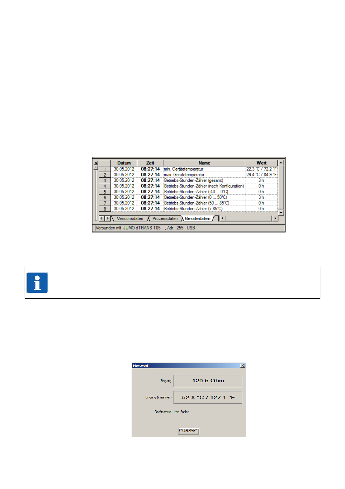
5.3.4 Betriebsstundenzähler
Mit der Betriebsstundenzähler-Funktion können die minimale und maximale Gerätetemperatur,
Betriebsstunden in verschiedenen Umgebungstemperaturbereichen und Betriebsstunden allgemein eingesehen werden. Um diese Daten anzuzeigen, muss im Setup-Programm im Menü
F
ENSTER die Option ONLINEDATEN mit einem Haken versehen und am unteren Rand des Fens-
ters der Setup-Software der Reiter G
5 Konfiguration
ERÄTEDATEN angewählt sein.
Der Betriebsstundenzähler (nach Konfiguration) kann unter dem Menüpunkt
XTRAS > BETRIEBSSTUNDENZÄHLER aufgerufen und zurückgesetzt werden. Alle anderen Be-
E
triebsstundenzähler können nicht zurückgesetzt werden.
HINWEIS!
Der errechnete Min.-/Max.-Zeitpunkt wird mit Stunden-Auflösung aus dem Rücksetzzeitpunkt
des Schleppzeigers abgeleitet.
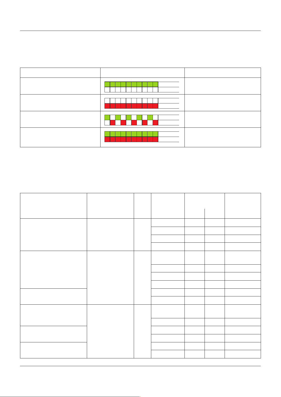
5.3.5 Aktuellen Messwert/Gerätestatus anzeigen
Im Setup-Programm kann mit der Funktion „Messwert anzeigen“ der aktuelle Wert des Eingangs sowie der linearisierte Wert angezeigt werden. Zusätzlich wir der momentane Gerätestatus angezeigt. Es werden Messbereichsüber- oder Unterschreitungen sowie
Verdrahtungsprobleme in Textform angezeigt. Die Funktion kann durch Klick auf den Button mit
dem Lupensymbol oder über das Menü mit E
XTRAS > MESSWERT ANZEIGEN aufgerufen.
25
Page 28

5 Konfiguration
26
Page 29
6.1 Technische Daten
Status grün
Status rot
Status grün
Status rot
Status grün
Status rot
Status grün
Status rot
6.1.1 LED-Signalisierung
Anzeige Muster Bedeutung
6 Anhang
Die zweifarbige LED leuchtet konti-
OK
nuierlich grün
Die zweifarbige LED leuchtet konti-
Sensorfehler
nuierlich rot
Die zweifarbige LED blinkt im Wechsel rot/grün
Die zweifarbige LED leuchtet kontinuierlich gleichzeitig rot und grün
Messbereichsüber-/
-unterschreitung
Initialisierungsphase,
Testmodus
„Fester Stromausgang“-Modus
6.1.2 Analogeingang
Alle Analogeingänge sind mit einem digitalen Filter 2. Ordnung ausgestattet (Filterkonstante
einstellbar von 0 ... 10 s) und haben eine Abtastrate von > 2 Messungen pro Sekunde.
Widerstandsthermometer
Bezeichnung Standard ITS Anschlussart Messbereich
in °C
Min. Max.
Messgenauig-
a
keit
Pt100 IEC 60751:2008 ITS-90 2/3-Leiter -100 200 ±0,2 K
Pt500 2/3-Leiter -200 850 ±0,4 K
Pt1000 4-Leiter -100 200 ±0,1 K
T
= 3,85 × 10⁻³¹/K 4-Leiter -200 850 ±0,2 K
K
Pt100 GOST 6651-
ITS-90 2/3-Leiter -100 200 ±0,2 K
2009 A.2
T
=3,917×10-31/K 2/3-Leiter -200 850 ±0,4 K
K
4-Leiter -100 200 ±0,15 K
4-Leiter -200 850 ±0,25 K
Pt50 2/3-Leiter -200 850 ±0,5 K
T
=3,91×10⁻³¹/K 4-Leiter -200 850 ±0,3 K
K
Ni100 DIN 43760 IPTS-682/3-Leiter -60 250 ±0,4 K
T
=6,18×10⁻³ 1/K 4-Leiter -60 250 ±0,2 K
K
Ni500 2/3-Leiter -60 250 ±0,4 K
T
=6,18 ×10⁻³ 1/K 4-Leiter -60 250 ±0,2 K
K
Ni1000 2/3-Leiter -60 250 ±0,4 K
T
=6,18×10⁻³ 1/K 4-Leiter -60 250 ±0,2 K
K
27
Page 30
6 Anhang
Bezeichnung Standard ITS Anschlussart Messbereich
in °C
Min. Max.
Ni100 GOST 6651-
2009 A.5
=6,17×10⁻³¹/K 4-Leiter -60 180 ±0,2 K
T
K
Cu50 GOST 6651-
2009 A.3
=4,28×10⁻³¹/K 4-Leiter -180 200 ±0,3 K
T
K
Cu100 2/3-Leiter -180 200 ±0,4 K
T
= 4,28 × 10⁻³¹/K 4-Leiter -180 200 ±0,2 K
K
a
Die Genauigkeitsangabe bezieht sich auf den gesamten Messbereichsumfang
Anschlussart Zwei-, Drei- oder Vierleiterschaltung
Sensorleitungswiderstand
- bei Drei-, Vierleiteranschluss 11 je Leitung
- bei Zweileiteranschluss Messwiderstand + 22 Innenleitungswiderstand
Sensorstrom < 0,3 mA
ITS-90 2/3-Leiter -60 180 ±0,4 K
ITS-90 2/3-Leiter -180 200 ±0,5 K
Messgenauigkeit
a
28
Page 31

Thermoelemente
6 Anhang
Bezeichnung Typ Standard ITS Messbereich
in °C
Min. Max.
Pt13Rh-Pt R IEC 584-1 ITS-90 -50 1768 ± 0,15 % ab +50 °C
Pt10Rh-Pt S IEC 584-1 ITS-90 -50 1768 ± 0,15 % ab +20 °C
Pt30Rh-Pt6Rh B IEC 584-1 ITS-90 0 1820 ± 0,15 % ab +400 °C
Fe-CuNi J IEC 584-1 ITS-90 -210 1200 ± 0,1 % ab -100 °C
Cu-CuNi T IEC 584-1 ITS-90 -270 400 ± 0,1 % ab -150 °C
NiCr-CuNi E IEC 584-1 ITS-90 -270 1000 ± 0,1 % ab -80 °C
NiCr-Ni K IEC 584-1 ITS-90 -270 1372 ± 0,1 % ab -80 °C
NiCrSi-NiSi N IEC 584-1 ITS-90 -270 1300 ± 0,1 % ab -80 °C
Fe-CuNi L DIN 43710 IPTS-68-200 900 0,1 %
Cu-CuNi U DIN 43710 IPTS-68-200 600 ± 0,1 % ab -100 °C
Chromel-Copel (Ni9,5CrCu44Ni)
Chromel-Alumel GOST R 8.585-2001 ITS-90 -270 1372 ± 0,1 % ab -80 °C
L GOST R 8.585-2001 ITS-90 -200 800 ± 0,1 % ab -80 °C
Messgenauigkeit
a
W5Re-W20Re A1 GOST R 8.585-2001 ITS-90 0 2500 ± 0,15 %
W5Re-W26Re C ASTM E230/E230M-11 ITS-90 0 2315 ± 0,15 %
W3Re-W25Re D ASTM E1751/E1751M-09ITS-90 0 2315 ± 0,25 %
PL II (Platinel
Vergleichsstelle Pt1000 intern oder externe Vergleichsstelle; Temperatur einstellbar 0 ... 80 °C
Vergleichsstellengenauigkeit ± 1 K
a
Die Genauigkeitsangabe bezieht sich auf den gesamten Messbereichsumfang
b
Platinel ist eine eingetragene Marke der Engelhardt Corp.
b
II) ASTM E1751/E1751M-09ITS-90 0 1395 ± 0,15 %
Widerstandspotenziometer/WFG und Widerstand/Poti
Bezeichnung Messbereich Messgenauigkeit
Widerstandspotenziometer/
WFG
Widerstand/Poti 400 400 m
Bis 10000 ±10
400 ... 4000 4
4000 ... 10000 10
Anschlussart Widerstandspotenziometer/WFG: Dreileiteranschluss
(A = Anfang, S = Schleifer, E = Ende)
Widerstand/Poti: Zwei-, Drei- und Vierleiteranschluss
29
Page 32

6 Anhang
Bezeichnung Messbereich Messgenauigkeit
Sensorleitungswiderstand 11 je Leitung bei Zwei-, Drei- und Vierleiteranschluss
Gleichspannung
Bezeichnung Messbereich Genauigkeit
Eingang für mV-Geber -100 ... 1100 mV ±0,05 % R
a
Die Genauigkeitsangabe bezieht sich auf den gesamten Messbereichsumfang
a
Eingangswiderstand
1M
E
6.1.3 Messkreisüberwachung
Typ 707050 Typ 707051
Messbereichsunterschreitung Linearer Abfall bis 3,8 mA Linearer Abfall bis 3,8 mA
(nach NAMUR-Empfehlung 43) (nach NAMUR-Empfehlung 43)
Linearer Abfall bis -0,12 V
Messbereichsüberschreitung Linearer Anstieg bis 20,5 mA Linearer Anstieg bis 20,5 mA
(nach NAMUR-Empfehlung 43) (nach NAMUR-Empfehlung 43)
Linearer Anstieg bis 10,31 V
Fühlerkurzschluss/Fühler- und
Leitungsbruch
Widerstandsthermometer: (konfigurierbar)
3,6 mA, 21,7 mA 3,6 mA, 21,7 mA
Oder freie Einstellung: 3,6 mA ... 23 mA Oder freie Einstellung: 3,6 mA ... 23 mA
Widerstandsthermometer: (konfigurierbar)
-0,2 V, 11,0 V
Oder freie Einstellung: -0,25 V ...
11,875 V
Thermoelement: (konfigurierbar)
3,6 mA, 21,7 mA 3,6 mA, 21,7 mA
Oder freie Einstellung: 3,6 mA ... 23 mA Oder freie Einstellung: 3,6 mA ... 23 mA
Strombegrenzung bei Fühlerkurzschluss oder Fühlerbruch
a
Für Thermoelement und mV-Geber ist eine Fühlerkurzschlusserkennung nicht möglich.
a
Thermoelement: (konfigurierbar)
-0,2 V oder 11,0 V
Oder freie Einstellung: -
0,25 V ... 11,875 V
23 mA
a
30
Page 33

6 Anhang
6.1.4 Ausgang
Typ 707050 Typ 707051
Ausgangssignal Eingeprägter Gleichstrom: Eingeprägter Gleichstrom:
Freie Einstellung: 4 ... 20 mA oder
20 ... 4 mA
galvanische Trennung Zwischen Ein- und Ausgang: Zwischen Ein- und Ausgang:
Prüfspannung Û = 3,75 kV/50 Hz Û = 1,875 kV/50 Hz
Übertragungsverhalten Linear, temperaturlinear
Kundenspezifisch
Reversion des Ausgangssignales
Sprungantwort 0 ... 100 % < 2 s (mit Filterkonstante 0 s)
Einschaltverzögerung 5 s (korrekter Messwert nach Anlegen der Versorgungsspannung)
Freie Einstellung: 4 ... 20 mA oder
20 ... 4 mA
Spannungssignal:
Freie Einstellung: 0 ... 10 V oder
10 ... 0 V
Stromausgang
Bürde (R
Bürdeneinfluss ±0,02 %/100
Abgleichbedingungen/-genau-
igkeit
Lastwiderstand 2k
Einfluss der Last ± 15 mV
Restwelligkeit ± 1 % bezogen auf 10 V, 0 ... 90 kHz
Abgleichbedingungen/-genau-
igkeit
a
Alle Angaben beziehen sich auf den Messbereichsendwert 20 mA
b
Alle Angaben beziehen sich auf den Messbereichsendwert 10 V
)R
b
DC 24 V bei ca. 22 °C/±0,05 %
DC 24 V bei ca. 22 °C/±0,05 %
=(Ub- 11 V)/0,022 A
b
Spannungsausgang
a
b
6.1.5 Kundenspezifische Linearisierung
Methode Eigenschaften
Wertepaare Anzahl max. 40
Interpolation: linear
Formel Anzahl Koeffizienten: 5
Polynom: 4. Ordnung
31
Page 34

6 Anhang
6.1.6 Spannungsversorgung
707050 707051
Spannungsversorgung (U
Spannungsversorgungseinfluss
a
Voraussetzung zur Nutzung des Spannungsausganges beim Typ 707051 ist eine Versorgungsspannung von mindestens 15 V
b
Alle Angaben beziehen sich auf den Messbereichsendwert 20 mA
) DC 11 ... 35 V (mit Verpolungsschutza)
b
Nur für Betrieb in SELV-, PELV-Stromkreisen nach DIN EN 50178
± 0,01 %/V Abweichung von 24 V
b
6.1.7 Umwelteinflüsse
707050 707051
Betriebstemperaturbereich -40 ... +85 °C -10 ... +70 °C
Lagertemperaturbereich -40 ... +100 °C -10 ... +70 °C
Temperatureinfluss
Widerstandsthermometer ±0,005 %/K Abweichung von 22 °C
Widerstandspotenziometer/
WFG
Widerstand/Poti ±0,01 %/K Abweichung von 22 °C
Thermoelement ±0,005 %/K Abweichung von 22 °Ca (zuzüglich Genauigkeit der Vergleichs-
Gleichspannung ±0,01 %/K Abweichung von 22 °C
Langzeitstabilität 0,1 K/Jahrb oder 0,05 %/Jahr
Klimafestigkeit
±0,01 %/K Abweichung von 22 °C
stelle)
a
a
a
a
c
Im Anschlusskopf Form B Rel. Feuchte 95 %, mit Betauung
Offene Montage Rel. Feuchte 95 %, ohne Betauung
Auf Hutschiene Rel. Feuchte 95 %, ohne Betauung
Vibrationsfestigkeit
DIN EN 60068-2-6 max. 2 g bei 10 ... 2000 Hz max. 2 g bei 10 ... 55 Hz
DIN EN 60068-2-27 Schock; 10 g/6 ms Schock; 10 g/6 ms
Germanischer Lloyd Kennlinie 2 Elektromagnetische Verträg-
lichkeit
(EMV)
Störaussendung Klasse B
Störfestigkeit Industrieanforderung
Nach DINEN61326-1
32
Page 35

6 Anhang
707050 707051
IP-Schutzart
Im Anschlusskopf Form B IP54/IP65 (je nach Ausführung)
Offene Montage IP00
Auf Hutschiene IP20
a
Alle Angaben beziehen sich auf den Messbereichsendwert 20 mA oder 10 V
b
Unter Abgleichbedingungen
c
% bezieht sich auf die eingestellte Messspanne. Der größere Wert der Langzeitstabilität ist gültig.
6.1.8 Gehäuse
707050 707051
Material Polycarbonat UL 94 V2 (vergossen) Polybutylenterephthalat UL 94 V0
Klemmenart Schraubklemmen: Schraubklemmen:
Art des Leiters Starre und flexible Leiter Starre und flexible Leiter
1,75 mm²; 0,2 mm² ... 2,5 mm²
AWG/kcmil min. 26, max 12
Abisolierlänge: 12 mm
Drehmoment max. 0,6 Nm Drehmoment 0,5 - 0,6 Nm
Federzugklemmen:
Starre und flexible Leiter
0,2 mm² ... 2,5 mm²
AWG/kcmil min. 26, max 12
Abisolierlänge: 8 mm
Montageart Im Anschlusskopf Form B (DIN EN
50446);
Im Aufbaugehäuse (siehe Zubehör); Oder TH 35-15 (DIN EN 60715);
Im Schaltschrank
(Befestigungselement erforderlich)
Einbaulage beliebig
Gewicht ~35g ~50g
Auf Hutschiene TH 35-7,5
33
Page 36

6 Anhang
34
Page 37

Page 38

JUMO GmbH & Co. KG
Moritz-Juchheim-Straße 1
36039 Fulda, Germany
Technischer Support Deutschland:
Te le f on :
Te le f ax :
E-Mail:
Internet:
+49 661 6003-727
+49 661 6003-508
mail@jumo.net
www.jumo.net
Te le f on :
Te le f ax :
E-Mail:
+49 661 6003-9135
+49 661 6003-881729
service@jumo.net
Lieferadresse:
Mackenrodtstraße 14
36039 Fulda, Germany
Postadresse:
36035 Fulda, Germany
JUMO Mess- und Regelgeräte Ges.m.b.H
Pfarrgasse 48
1232 Wien, Austria
Technischer Support Österreich:
Te le f on :
Te le f ax :
E-Mail:
Internet:
+43 1 610610
+43 1 6106140
info@jumo.at
www.jumo.at
Te le f on :
Te le f ax :
E-Mail:
+43 1 610610
+43 1 6106140
info@jumo.at
JUMO Mess- und Regeltechnik AG
Laubisrütistrasse 70
8712 Stäfa, Switzerland
Technischer Support Schweiz:
Te le f on :
Te le f ax :
E-Mail:
Internet:
+41 44 928 24 44
+41 44 928 24 48
info@jumo.ch
www.jumo.ch
Te le f on :
Te le f ax :
E-Mail:
+41 44 928 24 44
+41 44 928 24 48
info@jumo.ch
Page 39

JUMO dTRANS T05
Programmable 2-Wire Transmitter
B 707050.0
Operating Manual
2012-08-13/00576951
Page 40

Page 41

Contents
1 Introduction . . . . . . . . . . . . . . . . . . . . . . . . . . . . . . . . . . . . . . . . . . . . . . . . . . . . . .5
1.1 Safety information . . . . . . . . . . . . . . . . . . . . . . . . . . . . . . . . . . . . . . . . . . . . . . . . . . . . . . . . . . . . . 5
1.2 Brief description . . . . . . . . . . . . . . . . . . . . . . . . . . . . . . . . . . . . . . . . . . . . . . . . . . . . . . . . . . . . . . . 6
1.3 Block diagram . . . . . . . . . . . . . . . . . . . . . . . . . . . . . . . . . . . . . . . . . . . . . . . . . . . . . . . . . . . . . . . . 6
1.4 Dimensions . . . . . . . . . . . . . . . . . . . . . . . . . . . . . . . . . . . . . . . . . . . . . . . . . . . . . . . . . . . . . . . . . . 7
1.4.1 dTRANS T05 B (707050) transmitter . . . . . . . . . . . . . . . . . . . . . . . . . . . . . . . . . . . . . . . . . . . . . . 7
1.4.2 dTRANS T05 T (707051) transmitter . . . . . . . . . . . . . . . . . . . . . . . . . . . . . . . . . . . . . . . . . . . . . . 7
2 Identifying the device version . . . . . . . . . . . . . . . . . . . . . . . . . . . . . . . . . . . . . . .9
2.1 Nameplate . . . . . . . . . . . . . . . . . . . . . . . . . . . . . . . . . . . . . . . . . . . . . . . . . . . . . . . . . . . . . . . . . . . 9
2.2 Order details . . . . . . . . . . . . . . . . . . . . . . . . . . . . . . . . . . . . . . . . . . . . . . . . . . . . . . . . . . . . . . . . 10
2.3 Scope of delivery . . . . . . . . . . . . . . . . . . . . . . . . . . . . . . . . . . . . . . . . . . . . . . . . . . . . . . . . . . . . . 10
2.4 Accessories . . . . . . . . . . . . . . . . . . . . . . . . . . . . . . . . . . . . . . . . . . . . . . . . . . . . . . . . . . . . . . . . . 10
3 Installation . . . . . . . . . . . . . . . . . . . . . . . . . . . . . . . . . . . . . . . . . . . . . . . . . . . . . .11
3.1 Installation of the dTRANS T05 B . . . . . . . . . . . . . . . . . . . . . . . . . . . . . . . . . . . . . . . . . . . . . . . . 11
3.2 Installation/dismounting of dTRANS T05 T . . . . . . . . . . . . . . . . . . . . . . . . . . . . . . . . . . . . . . . . . 12
3.2.1 Connecting the wire to dTRANS T05 T with screw terminals . . . . . . . . . . . . . . . . . . . . . . . . . . . 12
3.2.2 Connecting the wire to dTRANS T05 T with spring-cage terminals . . . . . . . . . . . . . . . . . . . . . . 13
3.2.3 Opening the hinged cover . . . . . . . . . . . . . . . . . . . . . . . . . . . . . . . . . . . . . . . . . . . . . . . . . . . . . . 13
3.2.4 DIN rail installation . . . . . . . . . . . . . . . . . . . . . . . . . . . . . . . . . . . . . . . . . . . . . . . . . . . . . . . . . . . 14
4 Electrical connection . . . . . . . . . . . . . . . . . . . . . . . . . . . . . . . . . . . . . . . . . . . . .15
4.1 Safety information . . . . . . . . . . . . . . . . . . . . . . . . . . . . . . . . . . . . . . . . . . . . . . . . . . . . . . . . . . . . 15
4.2 Terminal assignment and dimensions (mm) of dTRANS T05 B . . . . . . . . . . . . . . . . . . . . . . . . . 15
4.3 Terminal assignment and dimensions (mm) of dTRANS T05 T . . . . . . . . . . . . . . . . . . . . . . . . . 17
4.4 PC interface for dTRANS T05, type B and T . . . . . . . . . . . . . . . . . . . . . . . . . . . . . . . . . . . . . . . . 18
5 Configuration . . . . . . . . . . . . . . . . . . . . . . . . . . . . . . . . . . . . . . . . . . . . . . . . . . . .19
5.1 Establishing connection between PC and transmitter . . . . . . . . . . . . . . . . . . . . . . . . . . . . . . . . . 19
5.2 Setup program . . . . . . . . . . . . . . . . . . . . . . . . . . . . . . . . . . . . . . . . . . . . . . . . . . . . . . . . . . . . . . . 20
5.3 Working with the setup program . . . . . . . . . . . . . . . . . . . . . . . . . . . . . . . . . . . . . . . . . . . . . . . . . 21
5.3.1 Establishing communication with the transmitter . . . . . . . . . . . . . . . . . . . . . . . . . . . . . . . . . . . . 21
5.3.2 Customer specific linearization . . . . . . . . . . . . . . . . . . . . . . . . . . . . . . . . . . . . . . . . . . . . . . . . . . 23
5.3.3 Drag indicator function . . . . . . . . . . . . . . . . . . . . . . . . . . . . . . . . . . . . . . . . . . . . . . . . . . . . . . . . 24
5.3.4 Operating hours counter . . . . . . . . . . . . . . . . . . . . . . . . . . . . . . . . . . . . . . . . . . . . . . . . . . . . . . . 25
5.3.5 Displaying the current measured value/device status . . . . . . . . . . . . . . . . . . . . . . . . . . . . . . . . . 25
6 Appendix . . . . . . . . . . . . . . . . . . . . . . . . . . . . . . . . . . . . . . . . . . . . . . . . . . . . . . .27
6.1 Technical data . . . . . . . . . . . . . . . . . . . . . . . . . . . . . . . . . . . . . . . . . . . . . . . . . . . . . . . . . . . . . . . 27
6.1.1 LED indication . . . . . . . . . . . . . . . . . . . . . . . . . . . . . . . . . . . . . . . . . . . . . . . . . . . . . . . . . . . . . . . 27
3
Page 42

Contents
6.1.2 Analog input . . . . . . . . . . . . . . . . . . . . . . . . . . . . . . . . . . . . . . . . . . . . . . . . . . . . . . . . . . . . . . . . 27
6.1.3 Measuring circuit monitoring . . . . . . . . . . . . . . . . . . . . . . . . . . . . . . . . . . . . . . . . . . . . . . . . . . . . 30
6.1.4 Output . . . . . . . . . . . . . . . . . . . . . . . . . . . . . . . . . . . . . . . . . . . . . . . . . . . . . . . . . . . . . . . . . . . . . 31
6.1.5 Customer-specific linearization . . . . . . . . . . . . . . . . . . . . . . . . . . . . . . . . . . . . . . . . . . . . . . . . . . 31
6.1.6 Voltage supply . . . . . . . . . . . . . . . . . . . . . . . . . . . . . . . . . . . . . . . . . . . . . . . . . . . . . . . . . . . . . . . 32
6.1.7 Environmental influences . . . . . . . . . . . . . . . . . . . . . . . . . . . . . . . . . . . . . . . . . . . . . . . . . . . . . . 32
6.1.8 Case . . . . . . . . . . . . . . . . . . . . . . . . . . . . . . . . . . . . . . . . . . . . . . . . . . . . . . . . . . . . . . . . . . . . . . 33
4
Page 43

1.1 Safety information
General information
This manual contains information that must be observed in the interest of your own safety and
to avoid damage to assets. This information is supported by symbols which are used in this
manual as follows.
Please read this manual before commissioning the device. Keep the manual in a place accessible to all users at all times.
If difficulties occur during commissioning, please refrain from carrying out any manipulations
that could jeopardize your warranty rights.
Warning signs
CAUTION!
This symbol in combination with the signal word indicates that damage to assets or data
loss will occur if suitable precautions are not taken.
Note signs
1 Introduction
TIP!
This symbol refers to important information about the product or its handling or additional
use.
5
Page 44

1 Introduction
Transmitter
707050
707051
:4to20mA
:4to20mA
0to10V
Output signals:
Supply voltage:
Setup
USB-interface:
Voltage
+
-
RTD
temperature probe
Resistance
transmitter
Input signals:
Thermocouple
DC 11 to 35 V
Resistor/
potentiometer
1.2 Brief description
The transmitters record sensor signals from RTD temperature probes, thermocouples, resistance transmitters, or resistances/potentiometers. When using a resistance/potentiometer or
RTD temperature probe, the sensor on the input side can be connected with a 2-wire, 3-wire,
or 4-wire circuit. Voltage signals in the range from -100 to +1100 mV can be recorded in the
same way. Depending on the selected measuring input, the linear and temperature-linear linearization variants and the possibility of easily configurable customer specific linearization are
available.
Type 707050 delivers 4 to 20 mA as an output signal. Type 707051 delivers 4 to 20 mA or 0 to
10 V as an output signal. The measuring input and the output signal are electrically isolated
from one another. It is possible to reverse the output signal in both types.
The transmitter configuration with respect to probe type, probe connection technology, measuring range (freely configurable), and linearization is carried out by means of a setup program on
the PC. The connection to the PC is established via a USB interface which does not require
additional auxiliary voltage. Via the USB interface, the min./max. process value and the min./
max. operating temperature recorded by the transmitter can be read and the sensor wiring can
be checked online.
The operating status of the transmitter is indicated by a two-color control LED (red/green). This
is lit green during fault-free operation. A fault such as a probe break will be shown by the corresponding LED indication.
1.3 Block diagram
6
Page 45

1.4 Dimensions
5Ø
44Ø
7Ø
33 21
101.2
102.5
6.3
93.1
1.4.1 dTRANS T05 B (707050) transmitter
1.4.2 dTRANS T05 T (707051) transmitter
1 Introduction
This figure shows type 707051 installed on a TH 35-7.5 DIN rail. The specifications concerning dimensions are only valid for installation on this DIN rail and change accordingly if a TH 35-15 DIN rail is
used.
7
Page 46

1 Introduction
8
Page 47

2.1 Nameplate
Nameplate specification Description Example
Typ Device type 707050/8-06
TN Part no. 00582219
F-Nr Fabrication number 0167938001012140001
Device type (Typ)
Compare the specifications on the respective nameplate to your order documents. The supplied device version can be identified using the order details in Chapter 2.2 "Order details",
page 10.
Part no. (TN)
The part no. clearly identifies an article in the catalog. It is important for communication between the customer and the sales department.
2 Identifying the device version
Voltage supply DC 11 to 35 V
Input symbol Programmable
Output symbol 4 to 20 mA
Fabrication no. (F-Nr)
Among other things, the fabrication number indicates the production date (year/week) and the
hardware version number.
Production date
Example: F-Nr = 0167938001012140001
The figures concerned are in positions 12, 13, 14, and 15 (from the left).
The device was produced in the 14th calendar week of 2012.
9
Page 48

2 Identifying the device version
2.2 Order details
(1) Basic type
707050 dTRANS T05 B - 2-wire transmitter
707051 dTRANS T05 T - 2-wire transmitter in mounting rail case
(2) Configuration
xx 8 Factory-set (0 to 100 °C, Pt100 3-wire circuit, 4 to 20 mA)
xx 9 Customer-specific setting
(3) Electrical connection type
xx 06 Screw terminals
x 07 Spring-cage terminals
(1) (2) (3)
Order code /-
Order example 707050 / 8 - 06
2.3 Scope of delivery
1 transmitter in the ordered version
For type 707050: including fastening material (2 screws, 2 pressure springs, and 2 retaining washers)
1 operating manual B 707050.0
2.4 Accessories
Article Part no.
Setup program on CD-ROM, multilingual 00574959
Operating manual B 707050.0 00576951
USB cable, A-connector on mini B-connector, length 3 m 00506252
Screw-on end clamp for mounting rail 00528648
Mounting element for installation of type 707050 on mounting rail 00352463
10
Page 49

3.1 Installation of the dTRANS T05 B
3 Installation
11
Page 50

3 Installation
3.2 Installation/dismounting of dTRANS T05 T
Installation Dismounting
3.2.1 Connecting the wire to dTRANS T05 T with screw terminals
12
Page 51

3 Installation
3.2.2 Connecting the wire to dTRANS T05 T with spring-cage terminals
3.2.3 Opening the hinged cover
TIP!
Close the hinged cover again after completing the configuration of the transmitter via the USB
port.
13
Page 52

3 Installation
3.2.4 DIN rail installation
Ensure that the device cannot slip off the DIN rail. For this purpose, attach end brackets for
mounting rails alongside the outermost devices on the DIN rail. These are available as accessories.
14
Page 53

4 Electrical connection
5Ø
44Ø
7Ø
33 21
2
1
+
–
4.1 Safety information
• The electrical connection must only be carried out by qualified personnel.
• When mounting, connecting, and operating the transmitter, ensure that no electrostatic
charging can take place.
• The transmitter is not suitable for installation and application areas with an explosion hazard.
• Never expose the transmitter to magnetic or electrical fields (e.g. caused by transformers,
walkie-talkies, or electrostatic discharge).
• An electrical connection that deviates from the connection diagram can destroy the transmitter.
• The transmitter is suitable for use in SELV or PELV current circuits according to protection
rating 3. The case implements basic insulation of up to 50 V towards neighboring devices.
4.2 Terminal assignment and dimensions (mm) of dTRANS T05 B
Connection for Terminal assignment
Voltage supply
Type 707050 R
DC 11 to 35 V
Current output R
4to20mA V
=(Vb- 11 V)/22 mA
B
= Load resistance
B
= Voltage supply
b
15
Page 54

4 Electrical connection
4
5
6
3
J
4
5
6
3
J
4
5
6
3
J
+
–
4
5
6
3
4
5
6
3
4
5
6
3
4
5
6
3
E
S
A
4
5
6
3
+
4
5
6
3
–
Connection for Terminal assignment
Analog inputs
RTD temperature probe R
2-wire circuit R
RTD temperature probe R
3-wire circuit (3W) R
RTD temperature probe R
4-wire circuit (4W) R
Thermocouple
Resistance/potentiometer R
2-wire circuit R
Resistance/potentiometer R
3-wire circuit (3W) R
11
L
= Lead wire resistance per wire
L
11
L
= Lead wire resistance per wire
L
11
L
= Lead wire resistance per wire
L
11
L
= Lead wire resistance per wire
L
11
L
= Lead wire resistance per wire
L
Resistance/potentiometer R
4-wire circuit (4W) R
11
L
= Lead wire resistance per wire
L
Resistance transmitter E = End
S = Slider
A = Start
Voltage 0to1V
16
Page 55

4 Electrical connection
101.2
102.5
6.2
93.1
A
B
A 5:1
B 5:1
2
1
+
–
4
3
+
–
6
7
8
5
J
J
6
7
8
5
J
6
7
8
5
4.3 Terminal assignment and dimensions (mm) of dTRANS T05 T
This figure shows type 707051 installed on a TH 35-7.5 DIN rail. The specifications concerning dimensions are
only valid for installation on this DIN rail and change accordingly if a TH 35-15 DIN rail is used.
Connection for Terminal assignment
Voltage supply
Type 707051 R
=(Vb- 11 V)/22 mA
B
DC 11 to 35 V
Current output R
4to20mA V
= Load resistance
B
= Voltage supply
b
Voltage output
0to10V
Analog inputs
RTD temperature probe R
2-wire circuit R
RTD temperature probe R
3-wire circuit (3W) R
11
L
= Lead wire resistance per wire
L
11
L
= Lead wire resistance per wire
L
RTD temperature probe R
4-wire circuit (4W) R
11
L
= Lead wire resistance per wire
L
17
Page 56

4 Electrical connection
6
7
8
5
+
–
6
7
8
5
6
7
8
5
6
7
8
5
6
7
8
5
E
S
A
6
7
8
5
+
–
Connection for Terminal assignment
Thermocouple
Resistance/potentiometer R
2-wire circuit R
Resistance/potentiometer R
3-wire circuit (3W) R
Resistance/potentiometer R
4-wire circuit (4W) R
11
L
= Lead wire resistance per wire
L
11
L
= Lead wire resistance per wire
L
11
L
= Lead wire resistance per wire
L
Resistance transmitter E = End
S = Slider
A = Start
Voltage0to1V
4.4 PC interface for dTRANS T05, type B and T
Connection for Type Terminal assignment
USB connection to the PC USB interface 2.0 (Mini-B; Full-
Standard (5-pin)
Speed)
18
Page 57

5 Configuration
(1)
(2)
(3)
(4)
5.1 Establishing connection between PC and transmitter
The connection between transmitter and PC is established via a USB cable.
Connection between PC and transmitter, using the example of type 707050
(1) Laptop/PC (3) Mini USB plug type B
(2) USB plug (4) USB socket for USB plug type B
For setup via USB, establish the following connections:
Step Activity
1 Insert the USB plug (2) of the USB cable into the laptop/PC (1).
2 Insert the mini USB plug (3) of the USB cable into the transmitter socket (4).
TIP!
If the connection between the PC and the transmitter is established via USB and the transmitter is not wired on the output side, the energy is supplied to the transmitter via the USB
interface of the PC. The current output (and the voltage output for dTRANS T05 T) and the
two-color LED are then not in operation.
When the transmitter is operated without a USB connection, the USB interface is deactivated.
TIP!
To guarantee smooth operation of the transmitter via a USB interface it must correspond to
USB specification 2.0.
CAUTION!
Do not connect the USB with a grounded sensor, even if the ground of the PC is grounded
(e.g. a desktop PC). The measuring input and the USB interface are not electrically isolated.
CAUTION!
Avoid a short circuit between the USB ground and the sensor terminals.
19
Page 58

5 Configuration
5.2 Setup program
The transmitter is configured on the PC with the setup program. The connection between transmitter and PC is established via a USB cable. The transmitter interface is a USB port of the
Mini-B type. It supports standard 2.0 "Full Speed". Once configuration of the transmitter has
been completed make sure that the attached hinged-on lid is back on the transmitter's USB interface.
Configurable parameters
Sensor type
Connection type 2/3-wire circuit or 4-wire circuit for RTD temperature probes or
resistors/potentiometers
Linearization
Customer-specific linearization
Sensor factor for thermocouple/RTD temperature probe
Lead wire resistance with 2-wire circuit
External or internal cold junction for thermocouple
Scaling
Digital filter
Offset
Unit
Behavior in the event of a probe break/short-circuit
Output signal increasing or decreasing (reversion)
Output functions, current 4 to 20 mA
Type 705050 and type 705051 4 to 20 mA scalable (start/end)
Output functions, voltage 0 to 10 V
Constant current source
20
Only type 705051 0 to 10 V scalable (start/end)
Constant voltage source
Page 59

TAG number (10-digit) and description (20-digit)
Installation date
Data pertaining to version, process and device of the transmitter can be displayed
Hardware and software requirements
For operation and the installation of the setup program the following hardware and software requirements have to be met.
Microsofta Windowsa XP, Windows Vistaa, Windows 7 32-bit/64-bit
1 GB RAM
200 MB free hard disk space
1 USB interface
a
Microsoft, Windows, and Windows Vista are registered trademarks of Microsoft Corporation.
5.3 Working with the setup program
5.3.1 Establishing communication with the transmitter
5 Configuration
The correct transmitter type must be selected in the setup program in order to use the setup
program to transfer a configuration to the transmitter or to establish the connection so that device data can be queried.
Device wizard with automatic detection of connected hardware
Step Activity
1 Connect the transmitter with the USB cable.
2 Start the setup program.
3 In the navigation window, double-click S
4 In the device wizard, select A
5 Once the correct type is displayed, click F
6 The transmitter is connected.
UTOMATIC DETECTION and click NEXT.
ETUP > CONFIGURATION > HARDWARE.
INISH.
➥ Device and process data can be displayed and data transfer is possible. This can be per-
formed via the menu D
DEVICE... or the corresponding buttons.
FROM
ATA TRANSFER > DATA TRANSFER TO DEVICE... or DATA TRANSFER
Device wizard with custom setting
Step Activity
1 Connect the transmitter with the USB cable.
2 Start the setup program.
3 In the navigation window, double-click S
4 In the device wizard, select U
SER-DEFINED SETTING and click NEXT.
ETUP > CONFIGURATION > HARDWARE.
21
Page 60

5 Configuration
Step Activity
5 Select the correct transmitter type and click NEXT.
6 Once the correct type is displayed, click F
7 The transmitter is connected.
➥ Device and process data can be displayed and data transfer is possible. This can be per-
formed via the menu D
DEVICE... or the corresponding buttons.
FROM
ATA TRANSFER > DATA TRANSFER TO DEVICE... or DATA TRANSFER
Saving/using an existing configuration
Once the configuration of a transmitter has been completed, the configuration can be saved
under F
ILE > SAVE AS .... All configured parameters and settings are saved in this setup file.
These can be accessed and changed at any time, even if no device is connected.
Step Activity
1 Start the setup program. The setup that was opened most recently will be opened again.
Close it if required.
2 Select a setup file under F
3 The configuration can also be performed without a transmitter being connected.
4 To load or read the configuration on a transmitter, the transmitter must be connected and
the connection must be established via the device manager or under D
E
STABLISH CONNECTION.
INISH.
ILE > OPEN and confirm with OPEN. The file is loaded.
ATA TRANSFER >
➥ Device and process data can be displayed and data transfer is possible. This can be per-
formed via the menu DATA TRANSFER > DATA TRANSFER TO DEVICE... or DATA TRANSFER
FROM
DEVICE... or the corresponding buttons.
22
Page 61

5.3.2 Customer specific linearization
The dTRANS T05 B and T transmitters provide the option of customer specific linearization of
measured values. The corresponding configuration screen can be accessed in the setup program via the E
ONFIGURATION > CUSTOMIZED LINEARIZATION. Linearization is performed via a table of values
C
or a 4th order polynomial.
DIT > CUSTOMIZED LINEARIZATION menu or in the tree structure under SETUP >
5 Configuration
Linearization on the basis of the 4th order polynomial
For linearization on the basis of the 4th order polynomial, the F
in the K
IND OF LINEARIZATION selection field. The coefficients of the polynomial can be entered
directly and the table is locked to entries. The graphic display is enabled by clicking the D
GRAPHIC
button.
Linearization on the basis of the table of values
If the linearization is to be performed using a table with value pairs, the T
selected in the K
IND OF LINEARIZATION selection field. It is not possible to enter polynomial co-
efficients. The X and Y values can then be entered in the table and displayed by clicking the
D
ISPLAY GRAPHIC button.
Linearization with calculated polynomial coefficients
If at least two value pairs are used for linearization, the setup program provides the option for
calculating the polynomial coefficients from these values. The linearization is then performed
on the basis of the polynomial. For this purpose, the T
lection field. If the respective value pairs are entered, the polynomial coefficients can be calculated automatically by clicking the f
ISPLAY GRAPHIC button. The following figures show the example of a table with value pairs and
D
button. The graphic display is enabled by clicking the
x
the graph of the value pairs with a superimposed graph of the polynomial.
ORMULA entry must be selected
ISPLAY
ABLE entry must be
ABLE entry must be selected in the se-
23
Page 62

5 Configuration
5.3.3 Drag indicator function
The drag indicator function records the minimum and maximum process variables (e.g. temperature) that appeared on the sensor during transmitter operation. These values can be reset.
The reset times for the drag indicator are saved in the device and are also displayed. In addition
to the actual minimum and maximum process values, the time at which the respective variables
occurred will be displayed – measured in operating hours since the reset time. This enables
conclusions to be drawn with regard to special features of the plant.
To view this data, the O
up program and the P
window.
NLINE DATA checkbox in the WINDOW menu must be selected in the set-
ROCESS DATA tab must be selected at the bottom of the setup program
24
The drag indicator can be reset via the menu item E
XTRAS > RESET DRAG INDICATOR.
Page 63

Example
In the figure above, the reset time of the minimum process variable is on June 19, 2012 at
08:21 a.m. Should you wish to establish the time at which the minimum process variable occurred, the value must be read in the corresponding line. In the example, this was 36.0 °C and
occurred 26 hours after the reset time. According to the example, the minimum process variable occurred on June 20, 2012 at 10:21 a.m.
5.3.4 Operating hours counter
The minimum and maximum device temperature, operating hours in various ambient temperature ranges, and overall operating hours can be viewed using the operating hours counter
function. To display this data, the O
in the setup program and the D
gram window.
EVICE DATA tab must be selected at the bottom of the setup pro-
5 Configuration
NLINE DATA checkbox in the WINDOW menu must be selected
The operating hours counter (according to the configuration) can be called up and reset via the
XTRAS > OPERATING HOURS COUNTER menu item. No other operating hours counters can be
E
reset.
TIP!
The calculated min./max. time is derived with hourly resolution from the reset time of the drag
indicator.
5.3.5 Displaying the current measured value/device status
In the setup program, the current input value and the linearized value can be displayed using
the "Display measured value" function. The current device status is also displayed. Values that
are out of range and wiring problems are displayed in text form. The function can be accessed
by clicking the button with the magnifying glass symbol or in the menu under E
MEASURED
VALUE.
XTRAS > DISPLAY
25
Page 64

5 Configuration
26
Page 65

6.1 Technical data
Status green
Status red
Status green
Status red
Status green
Status red
Status green
Status red
6.1.1 LED indication
Display Example Meaning
6 Appendix
The two-color LED is continually lit
green
The two-color LED is continually lit
red
The two-color LED alternately
flashes red/green
The two-color LED is continually lit
red and green simultaneously
6.1.2 Analog input
All analog inputs are equipped with a digital filter of second order (filter constant adjustable from
0 to 10 s) and have a sampling rate of > 2 measurements per second.
RTD temperature probe
Designation Standard ITS Connection
type
OK
Sensor error
Out of range
Initialization phase,
Test mode
"Permanent Current Output" mode
Measuring
range in °C
Measuring
accuracy
a
Min. Max.
Pt100 IEC 60751:2008 ITS-90 2/3-wire -100 200 ±0.2 K
Pt500 2/3-wire -200 850 ±0.4 K
Pt1000 4-wire -100 200 ±0.1 K
T
= 3.85 × 10⁻³¹/K 4-wire -200 850 ±0.2 K
K
Pt100 GOST 6651-
ITS-90 2/3-wire -100 200 ±0.2 K
2009 A.2
T
=3.917×10⁻³¹/K 2/3-wire -200 850 ±0.4 K
K
4-wire -100 200 ±0.15 K
4-wire -200 850 ±0.25 K
Pt50 2/3-wire -200 850 ±0.5 K
T
=3.91×10⁻³¹/K 4-wire -200 850 ±0.3 K
K
Ni100 DIN 43760 IPTS-682/3-wire -60 250 ±0.4 K
T
=6.18×10⁻³ 1/K 4-wire -60 250 ±0.2 K
K
Ni500 2/3-wire -60 250 ±0.4 K
T
=6.18 ×10⁻³ 1/K 4-wire -60 250 ±0.2 K
K
Ni1000 2/3-wire -60 250 ±0.4 K
T
=6.18×10⁻³ 1/K 4-wire -60 250 ±0.2 K
K
27
Page 66

6 Appendix
Designation Standard ITS Connection
type
Ni 100 GOST 6651-
2009 A.5
=6.17×10⁻³¹/K 4-wire -60 180 ±0.2 K
T
K
Cu50 GOST 6651-
2009 A.3
=4.28×10⁻³¹/K 4-wire -180 200 ±0.3 K
T
K
Cu100 2/3-wire -180 200 ±0.4 K
T
= 4.28 × 10⁻³¹/K 4-wire -180 200 ±0.2 K
K
a
The accuracy value refers to the complete measuring range.
Connection type 2-wire, 3-wire, or 4-wire circuit
Sensor lead resistance
- For 3/4-wire circuit 11 per line
- For 2-wire circuit Measuring resistance + 22 inner line resistance
Sensor current < 0.3 mA
ITS-90 2/3-wire -60 180 ±0.4 K
ITS-90 2/3-wire -180 200 ±0.5 K
Measuring
range in °C
Min. Max.
Measuring
accuracy
a
28
Page 67

Thermocouples
6 Appendix
Designation Type Standard ITS Measuring
range
in °C
Min. Max.
Pt13Rh-Pt R IEC 584-1 ITS-90 -50 1768 ± 0.15 % from
Pt10Rh-Pt S IEC 584-1 ITS-90 -50 1768 ± 0.15 % from
Pt30Rh-Pt6Rh B IEC 584-1 ITS-90 0 1820 ± 0.15 % from
Fe-CuNi J IEC 584-1 ITS-90 -210 1200 ± 0.1 % from -100 °C
Cu-CuNi T IEC 584-1 ITS-90 -270 400 ± 0.1 % from -150 °C
NiCr-CuNi E IEC 584-1 ITS-90 -270 1000 ± 0.1 % from -80 °C
NiCr-Ni K IEC 584-1 ITS-90 -270 1372 ± 0.1 % from -80 °C
NiCrSi-NiSi N IEC 584-1 ITS-90 -270 1300 ± 0.1 % from -80 °C
Fe-CuNi L DIN 43710 IPTS-68-200 900 0.1 %
Cu-CuNi U DIN 43710 IPTS-68-200 600 ± 0.1 % from -100 °C
Measuring accu-
a
racy
+50 °C
+20 °C
+400 °C
Chromel-Copel (Ni9.5CrCu44Ni)
Chromel-Alumel GOST R 8.585-2001 ITS-90 -270 1372 ± 0.1 % from -80 °C
W5Re-W20Re A1 GOST R 8.585-2001 ITS-90 0 2500 ± 0.15 %
W5Re-W26Re C ASTM E230/E230M-11 ITS-90 0 2315 ± 0.15 %
W3Re-W25Re D ASTM E1751/E1751M-09ITS-90 0 2315 ± 0.25 %
PL II (Platinel
Cold junction Pt1000 internal or external cold junction; temperature adjustable 0 to 80 °C
Cold junction accuracy ± 1 K
a
The accuracy values refer to the complete measuring range.
b
Platinel is a registered trademark of Engelhardt Corp.
b
II) ASTM E1751/E1751M-09ITS-90 0 1395 ± 0.15 %
L GOST R 8.585-2001 ITS-90 -200 800 ± 0.1 % from -80 °C
Resistance transmitter and resistor/potentiometer
Designation Measuring range Measuring accuracy
Resistance transmitter Up to 10000 ±10
Resistor/potentiometer 400 400 m
400 to 4000 4
4000 to 10000 10
29
Page 68

6 Appendix
Designation Measuring range Measuring accuracy
Connection type Resistance transmitter: 3-wire circuit
(A = Start, S = Slider, E = End)
Resistor/potentiometer: 2-wire circuit, 3-wire circuit, and 4-wire circuit
Sensor lead resistance 11 per line for 2-wire circuit, 3-wire circuit, and 4-wire circuit
Direct current
Designation Measuring range Accuracy
Input for mV generator -100 to 1100 mV ±0.05 % R
a
The accuracy value refers to the complete measuring range.
a
Input resistance
1M
E
6.1.3 Measuring circuit monitoring
Type 707050 Type 707051
Underrange Linear drop up to 3.8 mA Linear drop up to 3.8 mA
(According to NAMUR recommendation
43)
Overrange Linear increase up to 20.5 mA Linear increase up to 20.5 mA
(According to NAMUR recommendation
43)
Probe short-circuit/probe and
cable break
RTD temperature probe: (configurable) RTD temperature probe: (configurable)
3.6 mA, 21.7 mA 3.6 mA, 21.7 mA
(According to NAMUR recommendation
43)
Linear drop up to -0.12 V
(According to NAMUR recommendation
43)
Linear increase up to 10.31 V
Or free setting: 3.6mAto23mA Orfree setting: 3.6mAto23mA
-0.2 V, 11.0 V
Or free setting: -0.25 V to 11.875 V
Thermocouple: (configurable)
3.6 mA, 21.7 mA 3.6 mA, 21.7 mA
Or free setting: 3.6mAto23mA Or free setting: 3.6mAto23mA
Current limiting in the event of
a probe short circuit or probe
break
a
For thermocouples and mV generator a probe short-circuit detection is not possible.
a
Thermocouple: (configurable)
-0.2 V or 11.0 V
Or free setting: -0.25 V to 11.875 V
23 mA
30
a
Page 69

6 Appendix
6.1.4 Output
Type 707050 Type 707051
Output signal Load-independent direct current: Load-independent direct current:
Free setting:4to20mA or 20to4mA Free setting:4to20mA or 20to4mA
Voltage signal:
Free setting:0to10V or 10to0V
Electrical isolation Between input and output: Between input and output:
Test voltage Û = 3.75 kV/50 Hz Û = 1.875 kV/50 Hz
Transmission behavior Linear, temperature-linear
Customer specific
Reversion of the output signal
Step response 0 to 100 % < 2 s (with filter constant 0 s)
Switch-on delay 5 s (correct measured value after the supply voltage is applied)
Current output
Load (R
Load error ±0.02 %/100
Calibration conditions/accu-
racy
Load resistance 2k
)R
b
DC 24 V at approx. 22 °C/±0.05 %
=(Ub- 11 V)/0.022 A
b
Voltage output
a
Load influence ± 15 mV
Residual ripple ± 1 % referring to 10 V, 0 to 90 kHz
Calibration conditions/accu-
racy
a
All specifications refer to the measuring range end value of 20 mA
b
All specifications refer to the measuring range end value of 10 V
DC 24 V at approx. 22 °C/±0.05 %
6.1.5 Customer-specific linearization
Method Characteristics
Pairs of values Max. number: 40
Interpolation: linear
Formula Number of coefficients: 5
Polynomial: 4th order
b
31
Page 70

6 Appendix
6.1.6 Voltage supply
707050 707051
Voltage supply (U
Voltage supply error ± 0.01 %/V deviation from 24 V
a
Prerequisite for use of the voltage output of type 707051 is a supply voltage of at least 15 V
b
All specifications refer to the measuring range end value of 20 mA
) DC 11 to 35 V (with reverse voltage protectiona)
b
Only for operation in SELV, PELV current circuits according to DIN EN 50178
b
6.1.7 Environmental influences
707050 707051
Operating temperature range -40 to +85 °C -10 to +70 °C
Storage temperature range -40 to +100 °C -10 to +70 °C
Temperature influence
RTD temperature probe ±0.005 %/K deviation from 22 °C
Resistance transmitter ±0.01 %/K deviation from 22 °C
Resistor/potentiometer ±0.01 %/K deviation from 22 °C
Thermocouple ±0.005 %/K deviation from 22 °Ca (plus accuracy of the cold junction)
Direct current ±0.01 %/K deviation from 22 °C
Long-term stability 0.1 K/yearb or 0.05 %/year
Resistance to climatic condi-
tions
a
a
a
a
c
In terminal head, form B Rel. humidity 95 %, with condensation
Open assembly Rel. humidity 95 %, without condensa-
tion
On DIN rail Rel. humidity 95 %, without condensa-
tion
Vibration resistance
DIN EN 60068-2-6 Max. 2 g at 10 to 2000 Hz Max. 2 g at 10 to 55 Hz
DIN EN 60068-2-27 Shock; 10 g/6 ms Shock; 10 g/6 ms
Germanischer Lloyd Characteristic line 2 Electromagnetic compatibility
(EMC)
Interference emission Class B
Interference resistance Industrial requirements
According to DIN EN 61326-1
32
Page 71

6 Appendix
707050 707051
IP protection type
In terminal head, form B IP54/IP65 (depending on the version)
Open assembly IP00
On DIN rail IP20
a
All specifications refer to the measuring range end value of 20 mA or 10 V
b
Under calibration conditions
c
% refer to the set measuring span. The greater value of the long-term stability applies.
6.1.8 Case
707050 707051
Material Polycarbonate UL 94 V2 (grouted) Polybutylene terephthalate UL 94 V0
Terminal type Screw terminals: Screw terminals:
Wire type Rigid and flexible wires Rigid and flexible wires
1.75 mm²; 0.2 mm² to 2.5 mm²
AWG/kcmil min. 26, max 12
Stripping length 12 mm
Max. torque 0.6 Nm Torque 0.5 - 0.6 Nm
Spring-cage terminals
Rigid and flexible wires
0.2 mm² to 2.5 mm²
AWG/kcmil min. 26, max 12
Stripping length 8 mm
Assembly type In terminal head, form B (DIN EN
50446);
In the surface-mounted case (see
accessories);
In the control cabinet
(mounting element required)
Installation position Any
Weight ~35g ~50g
On DIN rail TH 35-7.5
Or TH 35-15 (DIN EN 60715);
33
Page 72

6 Appendix
34
Page 73

Page 74

JUMO GmbH & Co. KG
Street address:
Moritz-Juchheim-Straße 1
36039 Fulda, Germany
Delivery address:
Mackenrodtstraße 14
36039 Fulda, Germany
Postal address:
36035 Fulda, Germany
Phone: +49 661 6003-0
Fax: +49 661 6003-607
E-mail: mail@jumo.net
Internet: www.jumo.net
JUMO Instrument Co. Ltd.
JUMO House
Temple Bank, Riverway
Harlow - Essex CM20 2DY, UK
Phone: +44 1279 63 55 33
Fax: +44 1279 63 52 62
E-mail: sales@jumo.co.uk
Internet: www.jumo.co.uk
JUMO Process Control, Inc.
8 Technology Boulevard
Canastota, NY 13032, USA
Phone: 315-697-5866
1-800-554-JUMO
Fax: 315-697-5867
E-mail: info.us@jumo.net
Internet: www.jumousa.com
Page 75

JUMO dTRANS T05
Convertisseur de mesure
programmable en technique 2 fils
B 707050.0
Notice de mise en service
2012-08-13/00576951
Page 76

Page 77

Sommaire
1 Introduction . . . . . . . . . . . . . . . . . . . . . . . . . . . . . . . . . . . . . . . . . . . . . . . . . . . . . .5
1.1 Instructions relatives à la sécurité . . . . . . . . . . . . . . . . . . . . . . . . . . . . . . . . . . . . . . . . . . . . . . . . . 5
1.2 Description sommaire . . . . . . . . . . . . . . . . . . . . . . . . . . . . . . . . . . . . . . . . . . . . . . . . . . . . . . . . . . 6
1.3 Synoptique . . . . . . . . . . . . . . . . . . . . . . . . . . . . . . . . . . . . . . . . . . . . . . . . . . . . . . . . . . . . . . . . . . 6
1.4 Dimensions . . . . . . . . . . . . . . . . . . . . . . . . . . . . . . . . . . . . . . . . . . . . . . . . . . . . . . . . . . . . . . . . . . 7
1.4.1 Convertisseur de mesure dTRANS T05 B (707050) . . . . . . . . . . . . . . . . . . . . . . . . . . . . . . . . . . . 7
1.4.2 Convertisseur de mesure dTRANS T05 T (707051) . . . . . . . . . . . . . . . . . . . . . . . . . . . . . . . . . . . 7
2 Identification de l'exécution de l'appareil . . . . . . . . . . . . . . . . . . . . . . . . . . . . . .9
2.1 Plaque signalétique . . . . . . . . . . . . . . . . . . . . . . . . . . . . . . . . . . . . . . . . . . . . . . . . . . . . . . . . . . . . 9
2.2 Références de commande . . . . . . . . . . . . . . . . . . . . . . . . . . . . . . . . . . . . . . . . . . . . . . . . . . . . . 10
2.3 Matériel livré . . . . . . . . . . . . . . . . . . . . . . . . . . . . . . . . . . . . . . . . . . . . . . . . . . . . . . . . . . . . . . . . 10
2.4 Accessoires . . . . . . . . . . . . . . . . . . . . . . . . . . . . . . . . . . . . . . . . . . . . . . . . . . . . . . . . . . . . . . . . . 10
3 Montage . . . . . . . . . . . . . . . . . . . . . . . . . . . . . . . . . . . . . . . . . . . . . . . . . . . . . . . .11
3.1 Montage du dTRANS T05 B . . . . . . . . . . . . . . . . . . . . . . . . . . . . . . . . . . . . . . . . . . . . . . . . . . . . 11
3.2 Montage/Démontage du dTRANS T05 T . . . . . . . . . . . . . . . . . . . . . . . . . . . . . . . . . . . . . . . . . . 12
3.2.1 Raccordement du câble dTRANS T05 T par bornes à vis . . . . . . . . . . . . . . . . . . . . . . . . . . . . . 12
3.2.2 Raccordement du câble dTRANS T05 T par bornes à ressorts . . . . . . . . . . . . . . . . . . . . . . . . . 13
3.2.3 Ouverture du couvercle à charnière . . . . . . . . . . . . . . . . . . . . . . . . . . . . . . . . . . . . . . . . . . . . . . 13
3.2.4 Montage sur profilé chapeau . . . . . . . . . . . . . . . . . . . . . . . . . . . . . . . . . . . . . . . . . . . . . . . . . . . . 14
4 Raccordement électrique . . . . . . . . . . . . . . . . . . . . . . . . . . . . . . . . . . . . . . . . . .15
4.1 Instructions relatives à la sécurité . . . . . . . . . . . . . . . . . . . . . . . . . . . . . . . . . . . . . . . . . . . . . . . . 15
4.2 Brochage et dimensions (en mm) du dTRANS T05 B . . . . . . . . . . . . . . . . . . . . . . . . . . . . . . . . . 15
4.3 Brochage et dimensions (en mm) du dTRANS T05 T . . . . . . . . . . . . . . . . . . . . . . . . . . . . . . . . . 17
4.4 Interface PC pour dTRANS T05 types B et T . . . . . . . . . . . . . . . . . . . . . . . . . . . . . . . . . . . . . . . 18
5 Configuration . . . . . . . . . . . . . . . . . . . . . . . . . . . . . . . . . . . . . . . . . . . . . . . . . . . .19
5.1 Etablir la connexion entre PC et convertisseur de mesure . . . . . . . . . . . . . . . . . . . . . . . . . . . . . 19
5.2 Programme Setup . . . . . . . . . . . . . . . . . . . . . . . . . . . . . . . . . . . . . . . . . . . . . . . . . . . . . . . . . . . . 20
5.3 Travailler avec le programme Setup . . . . . . . . . . . . . . . . . . . . . . . . . . . . . . . . . . . . . . . . . . . . . . 21
5.3.1 Etablir la communication avec le convertisseur de mesure . . . . . . . . . . . . . . . . . . . . . . . . . . . . 21
5.3.2 Linéarisation spécifique . . . . . . . . . . . . . . . . . . . . . . . . . . . . . . . . . . . . . . . . . . . . . . . . . . . . . . . . 23
5.3.3 Fonction index . . . . . . . . . . . . . . . . . . . . . . . . . . . . . . . . . . . . . . . . . . . . . . . . . . . . . . . . . . . . . . . 24
5.3.4 Compteurs d’heures de fonctionnement . . . . . . . . . . . . . . . . . . . . . . . . . . . . . . . . . . . . . . . . . . . 25
5.3.5 Afficher la valeur mesurée en cours/l'état de l'appareil . . . . . . . . . . . . . . . . . . . . . . . . . . . . . . . . 25
6 Annexe . . . . . . . . . . . . . . . . . . . . . . . . . . . . . . . . . . . . . . . . . . . . . . . . . . . . . . . . .27
6.1 Caractéristiques techniques . . . . . . . . . . . . . . . . . . . . . . . . . . . . . . . . . . . . . . . . . . . . . . . . . . . . 27
6.1.1 LED de signalisation . . . . . . . . . . . . . . . . . . . . . . . . . . . . . . . . . . . . . . . . . . . . . . . . . . . . . . . . . . 27
3
Page 78

Sommaire
6.1.2 Entrée analogique . . . . . . . . . . . . . . . . . . . . . . . . . . . . . . . . . . . . . . . . . . . . . . . . . . . . . . . . . . . . 27
6.1.3 Surveillance du circuit de mesure . . . . . . . . . . . . . . . . . . . . . . . . . . . . . . . . . . . . . . . . . . . . . . . . 30
6.1.4 Sortie . . . . . . . . . . . . . . . . . . . . . . . . . . . . . . . . . . . . . . . . . . . . . . . . . . . . . . . . . . . . . . . . . . . . . . 31
6.1.5 Linéarisation spécifique . . . . . . . . . . . . . . . . . . . . . . . . . . . . . . . . . . . . . . . . . . . . . . . . . . . . . . . . 32
6.1.6 Alimentation . . . . . . . . . . . . . . . . . . . . . . . . . . . . . . . . . . . . . . . . . . . . . . . . . . . . . . . . . . . . . . . . . 32
6.1.7 Influences de l’environnement . . . . . . . . . . . . . . . . . . . . . . . . . . . . . . . . . . . . . . . . . . . . . . . . . . . 32
6.1.8 Boîtier . . . . . . . . . . . . . . . . . . . . . . . . . . . . . . . . . . . . . . . . . . . . . . . . . . . . . . . . . . . . . . . . . . . . . 33
4
Page 79

1.1 Instructions relatives à la sécurité
Généralité
Cette notice contient des instructions dont vous devez tenir compte aussi bien pour assurer
votre propre sécurité que pour éviter des dégâts matériels. Ces instructions sont appuyées par
des pictogrammes et sont utilisées dans cette notice comme indiqué.
Lisez cette notice avant de mettre en service l’appareil. Conservez-la dans un endroit accessible à tout moment par l’ensemble des utilisateurs.
Si vous rencontrez des difficultés lors de la mise en service, ne procédez à aucune manipulation qui pourrait compromettre votre droit à la garantie !
Symboles d'avertissement
ATTENTION !
Ce pictogramme associé à un mot clé signale que si l’on ne prend pas des mesures adéquates, cela provoque des dégâts matériels ou des pertes de données.
Symboles indiquant une remarque
1 Introduction
REMARQUE !
Ce pictogramme renvoie à une information importante sur le produit, sur son maniement
ou ses applications annexes.
5
Page 80

1 Introduction
Convertisseur de mesure
707050
707051
:4à20mA
:4à20mA
0à10V
Signaux de sortie :
Alimentation :
Setup
Port USB :
Tension
+
-
Sonde à
résistance
Potentiomètre
Signaux d’entrée :
Thermocouple
11à35VDC
Résistance/Rhéostat
1.2 Description sommaire
Les convertisseurs de mesure enregistrent les signaux des capteurs des sondes à résistance,
des thermocouples, potentiomètres ou rhéostats. Si on utilise un rhéostat ou une sonde à résistance, le raccordement du capteur du côté de l'entrée peut être de type 2, 3 ou 4 fils. Il est
également également possible d'enregistrer des signaux de type tension, dans la plage comprise entre -100 et +1100 mV. Suivant l'entrée de mesure choisie, différentes linéarisations sont
disponibles, linéaire, linéaire par rapport à la température ou configuration spécifique au client.
Comme signal de sortie, le type 707050 délivre un signal : 4 - 20 mA. Le type 707051 délivre
un signal de sortie 4 - 20 mA ou 0 - 10 V. L'entrée de mesure et le signal de sortie sont séparés
galvaniquement. Pour les deux types, il est possible d'inverser le signal de sortie.
Le logiciel Setup pour PC permet de configurer le convertisseur de mesure, en particulier le
type de sonde, la technique de raccordement de la sonde, l'étendue de mesure (réglage libre)
et la linéarisation. La connexion au PC s'effectue via un port USB qui ne nécessite pas de tension auxiliaire. Le port USB permet de lire les valeurs min./max. et les températures de fonctionnement min./max. enregistrées dans le convertisseur de mesure, et de vérifier en ligne le
câblage du capteur.
Le mode de fonctionnement du convertisseur de mesure est signalé par une LED de contrôle
bicolore (rouge/vert). Si le fonctionnement est normal, la LED est verte. S'il y a un défaut, par
exemple une rupture de sonde, celui-ci est indiqué par un clignotement.
1.3 Synoptique
6
Page 81

1.4 Dimensions
5Ø
44Ø
7Ø
33 21
101.2
102.5
6.3
93.1
1.4.1 Convertisseur de mesure dTRANS T05 B (707050)
1.4.2 Convertisseur de mesure dTRANS T05 T (707051)
1 Introduction
La figure montre le type 707051 monté sur profilé chapeau TH 35-7,5. Les cotes indiquées ne s'appliquent qu'au montage sur ce rail chapeau et changent si on utilise un profilé chapeau TH 35-15.
7
Page 82

1 Introduction
8
Page 83

2 Identification de l'exécution de l'appareil
2.1 Plaque signalétique
Indication de la plaque signalétique
Type Type d'appareil 707050/8-06
TN Référence article 00582219
F-Nr Numéro de série 0167938001012140001
Type d'appareil (type)
Comparez les indications de la plaque signalétique avec votre bon de commande. Vous pouvez identifier l'exécution livrée à l'aide du code d'identification dans Chapitre 2.2 "Références
de commande", page 10.
Référence article (TN)
Le numéro d’article identifie sans ambiguïté un article dans le catalogue. Il sert à la communication entre les clients et le service des ventes.
Numéro de série (F-Nr)
La date de fabrication (année/semaine) et le numéro de version du hardware peuvent être extraits du numéro de série.
Description Exemple
Alimentation 11à35V DC
Symbole pour entrée programmable
Symbole pour sortie 4 - 20 mA
Date de fabrication
Exemple : F-Nr = 0167938001012140001
Il s’agit des chiffres 12, 13, 14 et 15 (à partir de la gauche).
L'appareil a été produit en semaine 14 en 2012.
9
Page 84

2 Identification de l'exécution de l'appareil
2.2 Références de commande
(1) Type de base
707050 dTRANS T05 B - convertisseur de mesure en technique 2 fils
707051 dTRANS T05 T - convertisseur de mesure en technique 2 fils dans boîtier pour profilé
support
(2) Configuration
xx 8 Réglée en usine (0 à 100 °C, Pt100 montage 3 fils, 4 à 20 mA)
xx 9 Réglage spécifique au client
(3) Type de raccordement électrique
xx 06 Bornes à vis
x 07 Bornes à ressorts
(1) (2) (3)
Code de commande /-
Exemple de commande 707050 / 8 - 06
2.3 Matériel livré
1 convertisseur de mesure dans l'exécution commandée
Pour type 707050 : matériel de fixation compris (2 vis, 2 ressorts de pression et 2 rondelles d'arrêt)
1 notice de mise en service B 707050.0
2.4 Accessoires
Article Référence
Logiciel Setup sur CD-ROM, multilingue 00574959
Notice de mise en service B 707050.0 00576951
Câble USB, fiche mâle A/fiche mâle mini-B, longueur 3 m 00506252
Butée à visser pour profilé support 00528648
Elément de fixation pour montage du type 707050 sur profilé support 00352463
article
10
Page 85

3.1 Montage du dTRANS T05 B
3 Montage
11
Page 86

3 Montage
3.2 Montage/Démontage du dTRANS T05 T
Montage Démontage
3.2.1 Raccordement du câble dTRANS T05 T par bornes à vis
12
Page 87

3 Montage
3.2.2 Raccordement du câble dTRANS T05 T par bornes à ressorts
3.2.3 Ouverture du couvercle à charnière
REMARQUE !
Il faut refermer le couvercle à la fin de la configuration du convertisseur de mesure via le port
USB.
13
Page 88

3 Montage
3.2.4 Montage sur profilé chapeau
Il faut veiller à ce que l'appareil ne puisse pas glisser sur le profilé chapeau. Il faudrait fixer des
butées à cet effet sur le profilé chapeau. Elles sont disponibles en option.
14
Page 89

4 Raccordement électrique
5Ø
44Ø
7Ø
33 21
2
1
+
–
4.1 Instructions relatives à la sécurité
• Le raccordement électrique ne doit être effectué que par du personnel qualifié.
• Lors du montage, du raccordement et de la mise en service du convertisseur de mesure, il
faut veiller à ce qu'aucune charge électrostatique ne se produise.
• L’appareil n’est pas conçu pour être installé dans des zones exposées à un risque d’explosion.
• Le convertisseur de mesure ne doit être exposé à aucun champ magnétique ou électrique
(par ex. par des transformateurs, radiotéléphone ou décharge électrostatique).
• Un branchement électrique divergeant du schéma de raccordement peut endommager le
convertisseur de mesure.
• Le convertisseur de mesure peut être utilisé dans des circuits SELV ou PELV suivant indice
de protection 3. Le boîtier effectue une isolation de base jusqu'à 50 V aux appareils avoisinants.
4.2 Brochage et dimensions (en mm) du dTRANS T05 B
Raccordement pour Brochage
Alimentation
Type 707050 R
11 - 35 V DC
Sortie en courant R
4-20mA U
=(Ub-11V)/22mA
B
= résistance de charge
B
= alimentation
b
15
Page 90

4 Raccordement électrique
4
5
6
3
J
4
5
6
3
J
4
5
6
3
J
+
–
4
5
6
3
4
5
6
3
4
5
6
3
4
5
6
3
E
S
A
4
5
6
3
+
4
5
6
3
–
Raccordement pour Brochage
Entrées analogiques
Sonde à résistance R
en montage 2 fils R
Sonde à résistance R
en montage 3 fils (3W) R
Sonde à résistance R
en montage 4 fils (4W) R
Thermocouple
Rhéostat R
en montage 2 fils R
Rhéostat R
en montage 3 fils (3W) R
11
L
= résistance de ligne par conducteur
L
11
L
= résistance de ligne par conducteur
L
11
L
= résistance de ligne par conducteur
L
11
L
= résistance de ligne par conducteur
L
11
L
= résistance de ligne par conducteur
L
Rhéostat R
en montage 4 fils (4W) R
11
L
= résistance de ligne par conducteur
L
Potentiomètre E = fin
S = curseur
A = début
Ten sion 0 - 1 V
16
Page 91

4 Raccordement électrique
101.2
102.5
6.2
93.1
A
B
A 5:1
B 5:1
2
1
+
–
4
3
+
–
6
7
8
5
J
J
6
7
8
5
J
6
7
8
5
6
7
8
5
+
–
4.3 Brochage et dimensions (en mm) du dTRANS T05 T
La figure montre le type 707051 monté sur profilé chapeau TH 35-7,5. Les cotes indiquées ne s'appliquent qu'au
montage sur ce rail chapeau et changent si on utilise un profilé chapeau TH 35-15.
Raccordement pour Brochage
Alimentation
Type 707051 R
=(Ub-11V)/22mA
B
11 - 35 V DC
Sortie en courant R
4-20mA U
= résistance de charge
B
= alimentation
b
Sortie en tension
0-10V
Entrées analogiques
Sonde à résistance R
en montage 2 fils R
Sonde à résistance R
en montage 3 fils (3W) R
11
L
= résistance de ligne par conducteur
L
11
L
= résistance de ligne par conducteur
L
Sonde à résistance R
en montage 4 fils (4W) R
11
L
= résistance de ligne par conducteur
L
Thermocouple
17
Page 92

4 Raccordement électrique
6
7
8
5
6
7
8
5
6
7
8
5
6
7
8
5
E
S
A
6
7
8
5
+
–
Raccordement pour Brochage
Rhéostat RL 11
en montage 2 fils R
Rhéostat R
en montage 3 fils (3W) R
Rhéostat R
en montage 4 fils (4W) R
= résistance de ligne par conducteur
L
11
L
= résistance de ligne par conducteur
L
11
L
= résistance de ligne par conducteur
L
Potentiomètre E = fin
S = curseur
A = début
Ten sion 0 - 1 V
4.4 Interface PC pour dTRANS T05 types B et T
Raccordement pour Type Brochage
Liaison USB avec PC Port USB 2.0 (mini-B ; "Full-
Standard (5 broches)
Speed")
18
Page 93

5 Configuration
(1)
(2)
(3)
(4)
5.1 Etablir la connexion entre PC et convertisseur de mesure
La connexion entre PC et convertisseur de mesure s'effectue avec un câble USB.
Connexion entre PC et convertisseur de mesure à l'exemple du type 707050
(1) Ordinateur portable/PC (3) Connecteur mini USB, type B
(2) Connecteur USB (4) Prise USB pour connecteur USB, type B
Pour le Setup via le convertisseur USB/TTL, il faut procéder aux raccordements suivants :
Etape Action
1 Brancher le connecteur mâle USB du câble USB (2) dans l’ordinateur portable/PC (1).
2 Enficher le connecteur mini USB (3) du câble USB dans la prise du convertisseur de
mesure (4).
REMARQUE !
Lorsque la connexion entre PC et convertisseur de mesure s'effectue par USB et que le
convertisseur de mesure n'est pas câblé du côté de la sortie, le convertisseur est alimenté
via l'interface USB du PC. La sortie courant (pour dTRANS T05 T également la sortie tension)
ainsi que la LED bicolore sont alors hors service.
L'interface USB est désactivée lorsque le convertisseur de mesure fonctionne sans
connexion USB.
REMARQUE !
Pour assurer un fonctionnement sans problème du convertisseur de mesure avec une interface USB, celle-ci doit répondre aux spécifications USB 2.0.
ATTENTION !
Une connexion USB doit être évitée lorsque le capteur est relié à la terre même si la masse
du PC est reliée à la terre (par ex. ordinateur de table). Pas de séparation galvanique entre
entrée de mesure et une interface USB.
ATTENTION !
Il faut éviter tout court-circuit entre la masse USB et les bornes de raccordement du capteur
19
Page 94

5 Configuration
5.2 Programme Setup
Le logiciel Setup permet de configurer le convertisseur de mesure sur PC. La liaison entre le
convertisseur de mesure et le PC est établie via un câble USB. Pour l'interface du convertisseur de mesure, il s'agit d'un port USB de type mini-B. Il supporte la norme 2.0 "Full-Speed".
Après la configuration du convertisseur de mesure, il ne faut pas oublier de remettre le bouchon sur le port USB du convertisseur de mesure.
Paramètres configurables
Type de capteur
Type de raccordement - montage 2/3 ou 4 fils pour sonde à résistance ou rhéostat
Linéarisation
Linéarisation spécifique
Facteur du capteur pour thermocouple/sonde à résistance
Résistance de ligne pour montage 2 fils
Compensation de soudure froide externe ou interne pour thermocouple
Mise à l’échelle
Filtre numérique
Offset
Unité
Comportement si rupture/court-circuit de sonde
Signal de sortie croissant ou décroissant (inversion)
Fonctions de sortie Courant 4 à 20 mA
Type 705050 et type 705051 4 à 20 mA à échelle libre (début/fin)
Fonctions de sortie Tension 0 à 10 V
Uniquement type 705051 0 à 10 V à échelle libre (début/fin)
Source de courant constant
20
Source de tension constante
Page 95

5 Configuration
Numéro d'identification (10 caractères) et description (20 caractères)
Date d'installation
Logiciels et matériel nécessaires
Pour installer et utiliser le logiciel Setup, il faut satisfaire les conditions matérielles et logicielles
suivantes :
Microsofta Windowsa XP, Vista, Windows 7 32 bits/64 bits
1 Go de mémoire vive
200 Mo libres sur disque dur
1 port USB
a
Microsoft et Windows sont des marques déposées de Microsoft Corporation.
5.3 Travailler avec le programme Setup
5.3.1 Etablir la communication avec le convertisseur de mesure
Il faut sélectionner le bon convertisseur de mesure afin de pouvoir transférer via le programme
Setup une configuration ou établir la communication, consulter les données de l'appareil.
Assistant appareil avec détection automatique du hardware connecté
Etape Action
1 Connecter le convertisseur de mesure avec le câble USB.
2 Démarrer le programme Setup.
3 Dans la fenêtre de navigation double clic sur S
4 Sélectionner D
5 Lorsque le type correcte a été sélectionné, cliquer sur T
6 Le convertisseur de mesure est connecté.
ÉTECTION AUTOMATIQUE dans l'assistant appareil et cliquer sur CONTINUER.
ETUP > CONFIGURATION > HARDWARE.
ERMINER.
➥ Données appareil et données de process peuvent être affichées et le transfert de données
est possible. Ceci est possible via le menu T
NÉES VERS L'APP.... et/ou TRANSFERT DE DONNÉES DEPUIS L'APP... ou du bouton correspon-
RANSFERT DE DONNÉES > TRANSFERT DE DON-
dant.
Assistant appareil avec réglage personnalisé.
Etape Action
1 Connecter le convertisseur de mesure avec le câble USB.
2 Démarrer le logiciel Setup.
3 Dans la fenêtre de navigation double cliquez sur S
4 Sélectionner R
5 Sélectionner le type de convertisseur de mesure correcte et cliquer sur C
ÉGLAGE PERSONNALISÉ dans l'assistant appareil puis cliquer sur CONTINUER.
ETUP > CONFIGURATION > HARDWARE.
ONTINUER.
21
Page 96

5 Configuration
Etape Action
6 Lorsque le type correcte a été sélectionné, cliquer sur TERMINER.
7 Le convertisseur de mesure est connecté.
➥ Données appareil et données de process peuvent être affichées et le transfert de données
est possible. Ceci est possible via le menu T
NÉES VERS L'APP.... et/ou TRANSFERT DE DONNÉES DEPUIS L'APP... ou du bouton correspon-
dant.
Sauvegarde/Utilisation d'une configuration existante
Lorsque la configuration d'un convertisseur de mesure est terminée, celle-ci peut être mémorisée avec F
registrés dans ce fichier Setup. Ceux-ci peuvent être consultés et modifiés à tout moment, sans
qu'un appareil soit raccordé.
Etape Action
1 Démarrer le programme Setup. Ouverture sur le dernier Setup ouvert. Le fermer si néces-
ICHIER > ENREGISTRER SOUS... Tous les paramètres et réglages configurés sont en-
saire.
RANSFERT DE DONNÉES > TRANSFERT DE DON-
2 Sélectionner un fichier Setup via F
chargé.
3 Configuration possible même sans qu'un convertisseur de mesure ne soit raccordé.
4 Pour lire ou charger la configuration sur un convertisseur de mesure, celui-ci doit être rac-
cordé et la connexion doit être établie via le gestionnaire de l'appareil ou via T
DONNÉES > ETABLIR LA CONNEXION.
ICHIER > OUVRIR puis valider avec OUVRIR. Le fichier est
RANSFERT DE
➥ Données appareil et données de process peuvent être affichées et le transfert de données
est possible. Ceci est possible via le menu T
NÉES VERS L'APP.... et/ou TRANSFERT DE DONNÉES DEPUIS L'APP... ou du bouton correspon-
RANSFERT DE DONNÉES > TRANSFERT DE DON-
dant.
22
Page 97

5.3.2 Linéarisation spécifique
Linéarisation spécifique des valeurs mesurées possible avec les convertisseurs de mesure
dTRANS T05 B et T. Le masque de configuration est accessible soit dans le logiciel Setup soit
via le menu E
> CONFIGURATION > LINÉARISATION SPÉCIFIQUE. La linéarisation s'effectue via un tableau de va-
leurs ou un polynôme de 4ème ordre.
DITER > LINÉARISATION SPÉCIFIQUE ou dans la structure arborescente sous SETUP
5 Configuration
Linéarisation sur la base du polynôme de 4ème ordre.
Pour une linéarisation sur la base du polynôme de 4ème ordre, il faut sélectionner dans le
champ T
YPE DE LINÉARISATION la saisie FORMULE. Les coefficients du polynôme peuvent être
saisis directement et le tableau est verrouillé en ce qui concerne les saisies. Un clic sur le bou-
FFICHER GRAPHIQUE active l'affichage graphique.
ton A
Linéarisation sur la base du tableau des valeurs
En cas d'une linéarisation à l'aide d'un tableau avec paires de valeurs, il faut sélectionner dans
le champ T
YPE DE LINÉARISATION la saisie TABLEAU. Impossible de saisir les coefficients du po-
lynôme. Les valeurs X et Y peuvent alors être entrées dans le tableau et être représentées graphiquement par un clic sur le bouton A
FFICHER GRAPHIQUE.
Linéarisation avec coefficients du polynôme calculés
Si deux paires de valeurs au moins sont utilisées pour la linéarisation, le programme Setup permet de calculer à partir de ces coefficients de polynome. La linéarisation s'effectue alors sur la
base du polynôme. Pour cela, il faut d'abord sélectionner dans le champ de sélection T
Lorsque les paires de valeurs respectives sont saisies, les coefficients de polynôme peuvent
être calculés automatiquement par un clic sur le bouton f
PHIQUE active l'affichage graphique. Les images-écrans suivantes montrent un tableau avec
paires de valeurs ainsi que le graphique des paires de valeurs avec graphique du polynôme
superposé.
ABLEAU.
. Un clic sur le bouton AFFICHER GRA-
x
23
Page 98

5 Configuration
5.3.3 Fonction index
La fonction index permet d'enregistrer les grandeurs de process min. et max. (par ex. la température). Ces valeurs peuvent être remises à zéro. Les heures de remise à zéro de l'aiguille
sont sauvegardées dans l'appareil et sont également affichées. En plus des valeurs de process min. et max. effectives, est affichée l'heure d'apparition, mesurée en heures de fonctionnement depuis la remise à zéro. Ce qui permet de tirer des conclusions sur les particularités
de l'installation.
Pour pouvoir examiner ces données, il faut que dans le programme Setup sous menu F
l'option DONNÉES EN LIGNE soit cochée et qu'au bord inférieur de la fenêtre du logiciel Setup,
l'onglet D
ONNÉES DE PROCESS soit sélectionné.
ENÊTRE
24
L'index peut être remis à zéro sous le point de menu O
UTILS > REMETTRE L'INDEX À ZÉRO.
Page 99

Exemple
Dans l'image-écran ci-dessus, les grandeurs de process min. ont été remises à zéro le
18.09.2012 à 11h46. Lorsqu'on veut déterminer à quel moment est survenu la grandeur de pro-
cess min. , il faut que la valeur soit lue dans la ligne correspondante. Dans cette exemple, la
valeur est de 36.0 °C et est survenue 26 heures après la remise à zéro. Puis survint la valeur
min. le 19.09.2012 à 13h46.
5.3.4 Compteurs d’heures de fonctionnement
La fonction compteur d'heures de fonctionnement permet d'examiner la température min. et
max. de l'appareil, les heures de fonctionnement dans différentes plages de température ambiante et heures de fonctionnement en général. Pour afficher ces données, il faut que dans le
programme dans le menu F
rieur de la fenêtre du logiciel Setup, l'onglet D
ENÊTRE l'option DONNÉES EN LIGNE soit cochée et qu'au bord infé-
ONNÉES DE PROCESS soit sélectionné.
5 Configuration
Le compteur d'heures de fonctionnement (après configuration) peut être appelé sous
UTILS > COMPTEUR D'HEURES DE FONCTIONNEMENT puis remis à zéro. Les autres compteurs
O
de fonctionnement ne peuvent remis à zéro.
REMARQUE !
La date min./max. calculée est déduite avec résolution en heures de la date de réinitialisation
de l'index.
5.3.5 Afficher la valeur mesurée en cours/l'état de l'appareil
Il est possible d'afficher dans le programme Setup via la fonction „Afficher la valeur mesurée“
la valeur actuelle de l'entrée ainsi que la valeur linéarisée. L'état de l'appareil est également
indiqué. Les dépassements inférieurs ou supérieurs de l'étendue de mesure ainsi que les problèmes de câblage sont affichés sous forme de texte. La fonction peut être appelée par un clic
sur le bouton avec symbole de loupe ou via le menu avec O
SURÉE.
UTILS > AFFICHER LA VALEUR ME-
25
Page 100

5 Configuration
26
 Loading...