

Page 1
JUMO GmbH & Co. KG
Delivery address: Mackenrodtstraße 14
36039 Fulda, Germany
Postal address:
36035 Fulda, Germany
Phone: +49 661 6003-0
Fax: +49 661 6003-607
E-mail: mail@jumo.net
Internet: www.jumo.net
JUMO Instrument Co. Ltd.
JUMO House
Temple Bank, Riverway
Harlow, Essex CM20 2DY, UK
Phone: +44 1279 635533
Fax: +44 1279 635262
E-mail: sales@jumo.co.uk
Internet: www.jumo.co.uk
JUMO Process Control, Inc.
8 Technology Boulevard
Canastota, NY 13032, USA
Phone: 315-697-5866
1-800-554-JUMO
Fax: 315-697-5867
E-mail: info@jumo.us
Internet: www.jumo.us
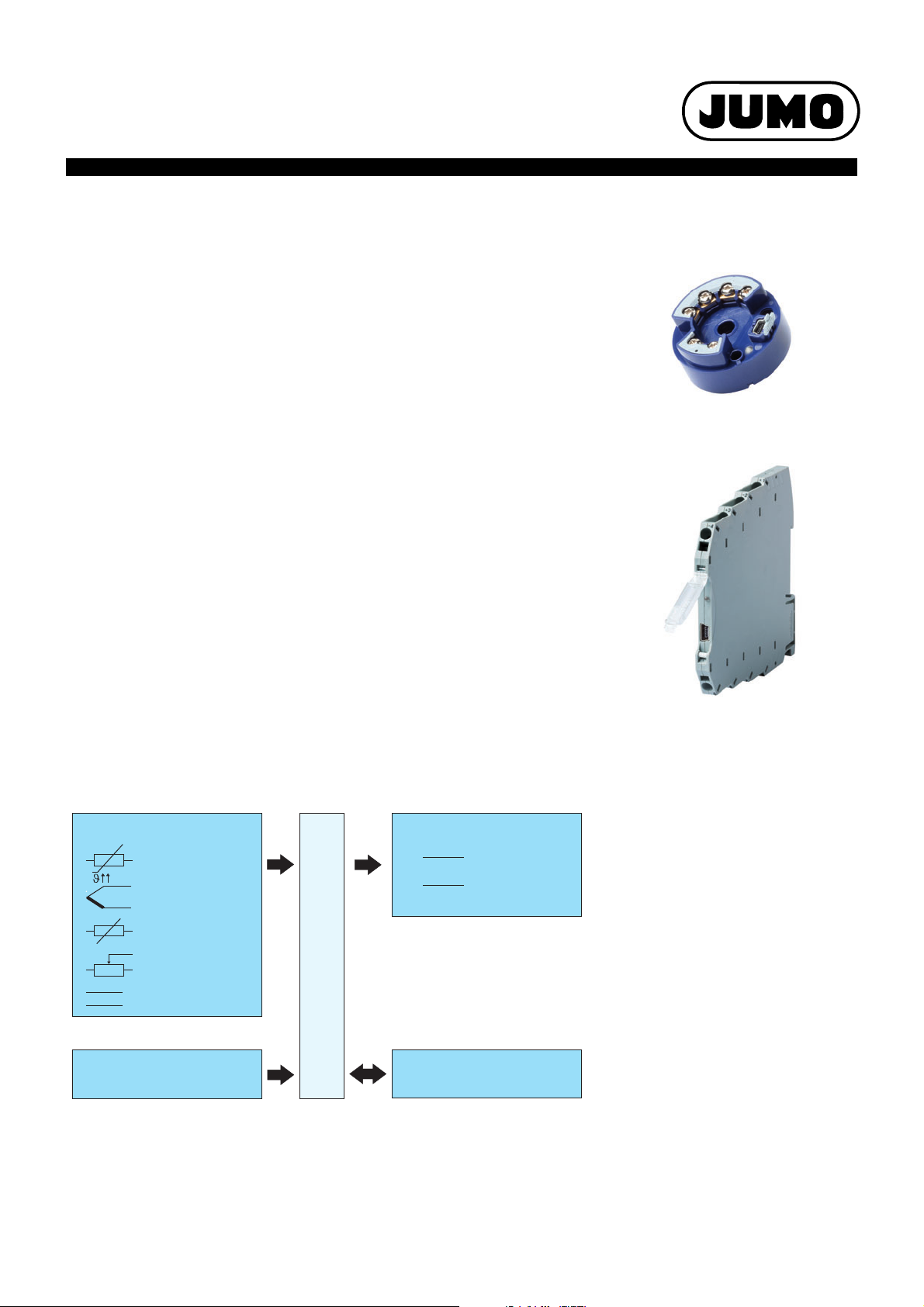
JUMO dTRANS T05
Transmitter
707050
707051
:4to20mA
:4to20mA
0to10V
Output signals:
Supply voltage:
Setup
USB-interface:
Voltage
+
-
RTD
temperature probe
Resistance
transmitter
Input signals:
Thermocouple
DC 11 to 35 V
Resistor/
potentiometer
Programmable 2-Wire Transmitter
- For installation into terminal head form B
- For installation on DIN rail
Brief description
The transmitters detect sensor signals by means of RTD temperature probes, thermocouples,
resistance transmitters, or resistors/potentiometers. When using a resistor/potentiometer or RTD
temperature probe, the sensor connection on the input side can be connected with a 2-wire, 3wire, or 4-wire circuit. Voltage signals in the range from -100 to +1100 mV can also be detected.
Depending on the selected measuring input the linearization variants linear, temperature-linear,
and the possibility of an easy configurable as well as customer-specific linearization are available.
Type 707050 delivers 4 to 20 mA as an output signal. Type 707051 offers an output signal of 4
to 20 mA or 0 to 10 V. The measuring input and the output signal are electrically isolated from
each other. Reversion of the output signal is possible for both types.
The transmitter configuration with respect to probe type, connection technology of the probe,
measuring range (freely adjustable), and linearization is carried out by means of a setup program
on the PC. The connection to the PC is established via a USB interface which does not require
additional auxiliary voltage. Via the USB interface the min./max. process value and the min./max.
operating temperature detected by the transmitter can be read and the sensor wiring can be
checked online.
The operating status of the transmitter is indicated by a two-color control LED (red/green). This
is lit green during operation without malfunctions. If a malfunction such as a probe break occurs
then the signal starts flashing.
Data Sheet 707050
Type 707050 (dTRANS T05 B)
Page 1/12
Block diagram
2012-06-04/00576949
Special features
• Measuring input for RTD temperature
probe, thermocouple, resistor/potentiometer,
resistance transmitter, and voltage
• Input and output are electrically isolated
• Control LED (red/green)
• Configuration directly via USB cable
(Mini-B) without additional auxiliary voltage
• Customer-specific linearization
• Detection of the min./max. process value
(drag pointer function including point in
time)
• Option to specify the temperature in °F for
temperature sensors
• Type 707051 available with screw terminals
or spring-cage terminals
Type 707051 (dTRANS T05 T)
Page 2

Data Sheet 707050 Page 2/12
JUMO GmbH & Co. KG
Delivery address: Mackenrodtstraße 14
36039 Fulda, Germany
Postal address:
36035 Fulda, Germany
Phone: +49 661 6003-0
Fax: +49 661 6003-607
E-mail: mail@jumo.net
Internet: www.jumo.net
JUMO Instrument Co. Ltd.
JUMO House
Temple Bank, Riverway
Harlow, Essex CM20 2DY, UK
Phone: +44 1279 635533
Fax: +44 1279 635262
E-mail: sales@jumo.co.uk
Internet: www.jumo.co.uk
JUMO Process Control, Inc.
8 Technology Boulevard
Canastota, NY 13032, USA
Phone: 315-697-5866
1-800-554-JUMO
Fax: 315-697-5867
E-mail: info@jumo.us
Internet: www.jumo.us
Technical data
Analog input
All analog inputs are equipped with a digital filter of second order (filter constant adjustable from 0 to 10 s) and have a sampling rate of > 2 measurements per second.
RTD temperature probe
Designation Standard ITS Connection type Measuring range
in °C
Measuring accuracy
Min. Max.
Pt100 IEC 60751:2008 ITS-90 2/3-wire -100 200 ±0.2 K
Pt500 2/3-wire -200 850 ±0.4 K
Pt1000 4-wire -100 200 ±0.1 K
T
= 3.85 × 10⁻³¹/K 4-wire -200 850 ±0.2 K
K
Pt100 GOST 6651-2009 A.2 ITS-90 2/3-wire -100 200 ±0.2 K
=3.917×10⁻³¹/K 2/3-wire -200 850 ±0.4 K
T
K
4-wire -100 200 ±0.15 K
4-wire -200 850 ±0.25 K
Pt50 2/3-wire -200 850 ±0.5 K
=3.91×10⁻³¹/K 4-wire -200 850 ±0.3 K
T
K
Ni100 DIN 43760 IPTS-68 2/3-wire -60 250 ±0.4 K
=6.18×10⁻³ 1/K 4-wire -60 250 ±0.2 K
T
K
Ni500 2/3-wire -60 250 ±0.4 K
=6.18 ×10⁻³ 1/K 4-wire -60 250 ±0.2 K
T
K
Ni1000 2/3-wire -60 250 ±0.4 K
=6.18×10⁻³ 1/K 4-wire -60 250 ±0.2 K
T
K
Ni 100 GOST 6651-2009 A.5 ITS-90 2/3-wire -60 180 ±0.4 K
=6.17×10⁻³¹/K 4-wire -60 180 ±0.2 K
T
K
Cu50 GOST 6651-2009 A.3 ITS-90 2/3-wire -180 200 ±0.5 K
=4.28×10⁻³¹/K 4-wire -180 200 ±0.3 K
T
K
Cu100 2/3-wire -180 200 ±0.4 K
= 4.28 × 10⁻³¹/K 4-wire -180 200 ±0.2 K
T
K
a
The accuracy value refers to the complete measuring range.
a
Connection type 2-wire, 3-wire, or 4-wire circuit
Sensor lead resistance
- For 3/4-wire circuit ≤ 11 Ω per line
- For 2-wire circuit Measuring resistance + ≤ 22 Ω inner line resistance
Sensor current < 0.3 mA
2012-06-04/00576949
Page 3

JUMO GmbH & Co. KG
Delivery address: Mackenrodtstraße 14
36039 Fulda, Germany
Postal address:
36035 Fulda, Germany
Phone: +49 661 6003-0
Fax: +49 661 6003-607
E-mail: mail@jumo.net
Internet: www.jumo.net
JUMO Instrument Co. Ltd.
JUMO House
Temple Bank, Riverway
Harlow, Essex CM20 2DY, UK
Phone: +44 1279 635533
Fax: +44 1279 635262
E-mail: sales@jumo.co.uk
Internet: www.jumo.co.uk
JUMO Process Control, Inc.
8 Technology Boulevard
Canastota, NY 13032, USA
Phone: 315-697-5866
1-800-554-JUMO
Fax: 315-697-5867
E-mail: info@jumo.us
Internet: www.jumo.us
Thermocouples
Data Sheet 707050 Page 3/12
Designation Type Standard ITS Measuring range
Measuring accuracy
in °C
Min. Max.
Pt13Rh-Pt R IEC 584-1 ITS-90 -50 1768 ± 0.15 % from +50 °C
Pt10Rh-Pt S IEC 584-1 ITS-90 -50 1768 ± 0.15 % from +20 °C
Pt30Rh-Pt6Rh B IEC 584-1 ITS-90 0 1820 ± 0.15 % from +400 °C
Fe-CuNi J IEC 584-1 ITS-90 -210 1200 ± 0.1 % from -100 °C
Cu-CuNi T IEC 584-1 ITS-90 -270 400 ± 0.1 % from -150 °C
NiCr-CuNi E IEC 584-1 ITS-90 -270 1000 ± 0.1 % from -80 °C
NiCr-Ni K IEC 584-1 ITS-90 -270 1372 ± 0.1 % from -80 °C
NiCrSi-NiSi N IEC 584-1 ITS-90 -270 1300 ± 0.1 % from -80 °C
Fe-CuNi L DIN 43710 IPTS-68 -200 900 ± 0.1 %
Cu-CuNi U DIN 43710 IPTS-68 -200 600 ± 0.1 % from -100 °C
Chromel-Copel (Ni9.5Cr-Cu44Ni) L GOST R 8.585-2001 ITS-90 -200 800 ± 0.1 % from -80 °C
Chromel-Alumel GOST R 8.585-2001 ITS-90 -270 1372 ± 0.1 % from -80 °C
W5Re-W20Re A1 GOST R 8.585-2001 ITS-90 0 2500 ± 0.15 %
W5Re-W26Re C ASTM E230/E230M-11 ITS-90 0 2315 ± 0.15 %
W3Re-W25Re D ASTM E1751/E1751M-09 ITS-90 0 2315 ± 0.25 %
PL II (Platinel
b
II)
ASTM E1751/E1751M-09 ITS-90 0 1395 ± 0.15 %
a
Cold junction Pt1000 internal or external cold junction; temperature adjustable 0 to 80 °C
Cold junction accuracy ± 1 K
a
The accuracy values refer to the complete measuring range.
b
Platinel is a registered trademark of Engelhardt Corp.
Resistance transmitter and resistor/potentiometer
Designation Measuring range Measuring accuracy
Resistance transmitter Up to 10000 Ω ±10 Ω
Resistor/potentiometer ≤ 400 Ω±400 mΩ
≥ 400 Ω to ≤ 4000 Ω± 4 Ω
> 4000 Ω to ≤ 10000 Ω±10 Ω
Connection type Resistance transmitter: 3-wire circuit
(A=Start,S=Slider,E=End)
Resistor/potentiometer: 2-wire circuit, 3-wire circuit, and 4-wire circuit
Sensor lead resistance ≤ 11 Ω per line for 2-wire circuit, 3-wire circuit, and 4-wire circuit
Direct current
Designation Measuring range Accuracy
a
Input for mV generator -100 to 1100 mV ±0.05 % R
a
The accuracy value refers to the complete measuring range.
Input resistance
E
≥ 1MΩ
2012-06-04/00576949
Page 4

Data Sheet 707050 Page 4/12
JUMO GmbH & Co. KG
Delivery address: Mackenrodtstraße 14
36039 Fulda, Germany
Postal address:
36035 Fulda, Germany
Phone: +49 661 6003-0
Fax: +49 661 6003-607
E-mail: mail@jumo.net
Internet: www.jumo.net
JUMO Instrument Co. Ltd.
JUMO House
Temple Bank, Riverway
Harlow, Essex CM20 2DY, UK
Phone: +44 1279 635533
Fax: +44 1279 635262
E-mail: sales@jumo.co.uk
Internet: www.jumo.co.uk
JUMO Process Control, Inc.
8 Technology Boulevard
Canastota, NY 13032, USA
Phone: 315-697-5866
1-800-554-JUMO
Fax: 315-697-5867
E-mail: info@jumo.us
Internet: www.jumo.us
Measuring circuit monitoring
Type 707050 Type 707051
Underrange Linear drop up to 3.8 mA Linear drop up to 3.8 mA
(According to NAMUR recommendation 43) (According to NAMUR recommendation 43)
Linear drop up to -0.12 V
Overrange Linear increase up to 20.5 mA Linear increase up to 20.5 mA
(According to NAMUR recommendation 43) (According to NAMUR recommendation 43)
Linear increase up to 10.31 V
Probe short-circuit/probe and
cable break
Current limiting in the event of a probe
short circuit or probe break
a
For thermocouples and mV generator a probe short-circuit detection is not possible.
RTD temperature probe: (configurable) RTD temperature probe: (configurable)
≤ 3.6 mA, ≥ 21.7 mA ≤ 3.6 mA, ≥ 21.7 mA
Or free setting: 3.6 mA to 23 mA Or free setting: 3.6 mA to 23 mA
≤ -0.2 V, ≥ 11. 0 V
Or free setting: -0.25 V to 11.875 V
Thermocouple: (configurable)
a
Thermocouple: (configurable)
≤ 3.6 mA, ≥ 21.7 mA ≤ 3.6 mA, ≥ 21.7 mA
Or free setting: 3.6 mA to 23 mA Or free setting: 3.6 mA to 23 mA
≤ -0.2 V or ≥ 11 .0 V
Or free setting: -0.25 V to 11.875 V
≤ 23 mA
a
Output
Type 707050 Type 707051
Output signal Load-independent direct current: Load-independent direct current:
Free setting: 4 to 20 mA or 20 to 4 mA Free setting: 4 to 20 mA or 20 to 4 mA
Voltage signal:
Free setting: 0 to 10 V or 10 to 0 V
Electrical isolation Between input and output: Between input and output:
Test voltage Û = 3.75 kV/50 Hz Û = 1.875 kV/50 Hz
Transmission behavior Linear, temperature-linear
Customer specific
Reversion of the output signal
Step response 0 to 100 % < 2 s (with filter constant 0 s)
Switch-on delay 5 s (correct measured value after the supply voltage is applied)
Current output
Load (R
Load error ≤ ±0.02 %/100 Ω
Calibration conditions/accuracy DC 24 V at approx. 22 °C/±0.05 %
Load resistance ≥ 2kΩ
Load influence ±15mV
Residual ripple ± 1 % referring to 10 V, 0 to 90 kHz
Calibration conditions/accuracy DC 24 V at approx. 22 °C/±0.05 %
a
b
2012-06-04/00576949
)R
b
=(Ub- 11 V)/0.022 A
b
a
Voltage output
b
All specifications refer to the measuring range end value of 20 mA
All specifications refer to the measuring range end value of 10 V
Page 5

JUMO GmbH & Co. KG
Delivery address: Mackenrodtstraße 14
36039 Fulda, Germany
Postal address:
36035 Fulda, Germany
Phone: +49 661 6003-0
Fax: +49 661 6003-607
E-mail: mail@jumo.net
Internet: www.jumo.net
JUMO Instrument Co. Ltd.
JUMO House
Temple Bank, Riverway
Harlow, Essex CM20 2DY, UK
Phone: +44 1279 635533
Fax: +44 1279 635262
E-mail: sales@jumo.co.uk
Internet: www.jumo.co.uk
JUMO Process Control, Inc.
8 Technology Boulevard
Canastota, NY 13032, USA
Phone: 315-697-5866
1-800-554-JUMO
Fax: 315-697-5867
E-mail: info@jumo.us
Internet: www.jumo.us
Customer-specific linearization
Method Characteristics
Pairs of values Max. number: 40
Interpolation: linear
Formula Number of coefficients: 5
Polynomial: 4th order
Voltage supply
707050 707051
Data Sheet 707050 Page 5/12
Voltage supply (U
Voltage supply error ≤ ± 0.01 %/V deviation from 24 V
a
Prerequisite for use of the voltage output of type 707051 is a supply voltage of at least 15 V
b
All specifications refer to the measuring range end value of 20 mA
) DC 11 to 35 V (with reverse voltage protectiona)
b
Only for operation in SELV, PELV current circuits according to DIN EN 50178
b
Environmental influences
707050 707051
Operating temperature range -40 to +85 °C -10 to +70 °C
Storage temperature range -40 to +100 °C -10 to +70 °C
Temperature influence
RTD temperature probe ≤ ±0.005 %/K deviation from 22 °C
Resistance transmitter ≤ ±0.01 %/K deviation from 22 °C
Resistor/potentiometer ≤ ±0.01 %/K deviation from 22 °C
Thermocouple ≤ ±0.005 %/K deviation from 22 °Ca (plus accuracy of the cold junction)
Direct current ≤ ±0.01 %/K deviation from 22 °C
Long-term stability ≤ 0.1 K/yearb or ≤ 0.05 %/year
Resistance to climatic conditions
In terminal head, form B Rel. humidity ≤ 95 %, with condensation
Open assembly Rel. humidity ≤ 95 %, without condensation
On DIN rail Rel. humidity ≤ 95 %, without condensation
Vibration resistance
DIN EN 60068-2-6 Max. 2 g at 10 to 2000 Hz Max. 2 g at 10 to 55 Hz
DIN EN 60068-2-27 Shock; 10 g/6 ms Shock; 10 g/6 ms
Germanischer Lloyd Characteristic line 2 -
Electromagnetic compatibility
(EMC)
Interference emission Class B
Interference resistance Industrial requirements
a
a
a
a
c
According to DIN EN 61326-1
2012-06-04/00576949
Page 6

Data Sheet 707050 Page 6/12
JUMO GmbH & Co. KG
Delivery address: Mackenrodtstraße 14
36039 Fulda, Germany
Postal address:
36035 Fulda, Germany
Phone: +49 661 6003-0
Fax: +49 661 6003-607
E-mail: mail@jumo.net
Internet: www.jumo.net
JUMO Instrument Co. Ltd.
JUMO House
Temple Bank, Riverway
Harlow, Essex CM20 2DY, UK
Phone: +44 1279 635533
Fax: +44 1279 635262
E-mail: sales@jumo.co.uk
Internet: www.jumo.co.uk
JUMO Process Control, Inc.
8 Technology Boulevard
Canastota, NY 13032, USA
Phone: 315-697-5866
1-800-554-JUMO
Fax: 315-697-5867
E-mail: info@jumo.us
Internet: www.jumo.us
707050 707051
IP protection type
In terminal head, form B IP54/IP65 (depending on the version)
Open assembly IP00
On DIN rail IP20
a
All specifications refer to the measuring range end value of 20 mA or 10 V
b
Under calibration conditions
c
% refer to the set measuring span. The greater value of the long-term stability applies.
Case
707050 707051
Material Polycarbonate UL 94 V2 (grouted) Polybutylene terephthalate UL 94 V0
Terminal type Screw terminals: Screw terminals:
Wire type Rigid and flexible wires Rigid and flexible wires
≤ 1.75 mm²; 0.2 mm² to 2.5 mm²
AWG/kcmil min. 26, max 12
Stripping length 12 mm
Max. torque 0.6 Nm Torque 0.5 - 0.6 Nm
Spring-cage terminals
Rigid and flexible wires
0.2 mm² to 2.5 mm²
AWG/kcmil min. 26, max 12
Stripping length 8 mm
Assembly type In terminal head, form B (DIN EN 50446); On DIN rail TH 35-7.5
In the surface-mounted case (see accessories); Or TH 35-15 (DIN EN 60715);
In the control cabinet
(mounting element required)
Installation position Any
Weight ~35g ~50g
Approval/approval marks
None
2012-06-04/00576949
Page 7

Data Sheet 707050 Page 7/12
JUMO GmbH & Co. KG
Delivery address: Mackenrodtstraße 14
36039 Fulda, Germany
Postal address:
36035 Fulda, Germany
Phone: +49 661 6003-0
Fax: +49 661 6003-607
E-mail: mail@jumo.net
Internet: www.jumo.net
JUMO Instrument Co. Ltd.
JUMO House
Temple Bank, Riverway
Harlow, Essex CM20 2DY, UK
Phone: +44 1279 635533
Fax: +44 1279 635262
E-mail: sales@jumo.co.uk
Internet: www.jumo.co.uk
JUMO Process Control, Inc.
8 Technology Boulevard
Canastota, NY 13032, USA
Phone: 315-697-5866
1-800-554-JUMO
Fax: 315-697-5867
E-mail: info@jumo.us
Internet: www.jumo.us
Setup program
The transmitter is configured on the PC with the setup program. The connection between transmitter and PC is established via a USB cable. The
transmitter interface is a USB port of the Mini-B type. It supports standard 2.0 "Full Speed". Once configuration of the transmitter has been completed make sure that the attached hinged-on lid is back on the transmitter's USB interface.
Configurable parameters
Sensor type
Connection type 2/3-wire circuit or 4-wire circuit for RTD temperature probes or resistors/potentiometers
Linearization
Customer-specific linearization
Sensor factor for thermocouple/RTD temperature probe
Lead wire resistance with 2-wire circuit
External or internal cold junction for thermocouple
Scaling
Digital filter
Offset
Unit
Behavior in the event of a probe break/short-circuit
Output signal increasing or decreasing (reversion)
Output functions, current 4 to 20 mA
Type 705050 and type 705051 4 to 20 mA scalable (start/end)
Constant current source
Output functions, voltage 0 to 10 V
Only type 705051 0 to 10 V scalable (start/end)
Constant voltage source
TAG number (10-digit) and description (20-digit)
Installation date
Data pertaining to version, process and device of the transmitter can be displayed
2012-06-04/00576949
Page 8

Data Sheet 707050 Page 8/12
JUMO GmbH & Co. KG
Delivery address: Mackenrodtstraße 14
36039 Fulda, Germany
Postal address:
36035 Fulda, Germany
Phone: +49 661 6003-0
Fax: +49 661 6003-607
E-mail: mail@jumo.net
Internet: www.jumo.net
JUMO Instrument Co. Ltd.
JUMO House
Temple Bank, Riverway
Harlow, Essex CM20 2DY, UK
Phone: +44 1279 635533
Fax: +44 1279 635262
E-mail: sales@jumo.co.uk
Internet: www.jumo.co.uk
JUMO Process Control, Inc.
8 Technology Boulevard
Canastota, NY 13032, USA
Phone: 315-697-5866
1-800-554-JUMO
Fax: 315-697-5867
E-mail: info@jumo.us
Internet: www.jumo.us
Recorder
-+
Displaydevice
- +
Controller
- +
2-wire
transmitter
=
+
-
4to20mA
Power
supply unit
DC 11 to 30 V
+
-
_
~
1
2
J
5Ø
44Ø
7Ø
33 21
Hardware and software requirements
For operation and the installation of the setup program the following hardware and software requirements have to be met.
Microsofta Windowsa XP, Windows Vista, Windows 7 32-bit/64-bit
1 GB RAM
200 MB free hard disk space
1 USB interface
a
Microsoft and Windows are registered trademarks of Microsoft Corporation.
Connection diagram
The connection diagram in the data sheet provides preliminary information about the connection possibilities. Only use the operating manual for
the electrical connection. The knowledge and the correct technical execution of the safety information/instructions contained in these documents
are a prerequisite for installation, electrical connection, and startup as well as for safety during operation.
Connection example dTRANS T05 B
Terminal assignment and dimensions (mm) dTRANS T05 B
2012-06-04/00576949
Page 9

JUMO GmbH & Co. KG
Delivery address: Mackenrodtstraße 14
36039 Fulda, Germany
Postal address:
36035 Fulda, Germany
Phone: +49 661 6003-0
Fax: +49 661 6003-607
E-mail: mail@jumo.net
Internet: www.jumo.net
JUMO Instrument Co. Ltd.
JUMO House
Temple Bank, Riverway
Harlow, Essex CM20 2DY, UK
Phone: +44 1279 635533
Fax: +44 1279 635262
E-mail: sales@jumo.co.uk
Internet: www.jumo.co.uk
JUMO Process Control, Inc.
8 Technology Boulevard
Canastota, NY 13032, USA
Phone: 315-697-5866
1-800-554-JUMO
Fax: 315-697-5867
E-mail: info@jumo.us
Internet: www.jumo.us
Connection for Terminal assignment
2
1
+
–
4
5
6
3
J
4
5
6
3
J
4
5
6
3
J
+
–
4
5
6
3
4
5
6
3
4
5
6
3
4
5
6
3
E
S
A
4
5
6
3
+
4
5
6
3
–
Voltage supply
Type 707050 R
=(Ub-11V)/22mA
B
DC 11 to 35 V
Data Sheet 707050 Page 9/12
Current output R
4to20mA U
Analog inputs
RTD temperature probe R
2-wire circuit R
RTD temperature probe R
3-wire circuit (3W) R
RTD temperature probe R
4-wire circuit (4W) R
Thermocouple
Resistor/potentiometer R
2-wire circuit R
Resistor/potentiometer R
3-wire circuit (3W) R
= Load resistance
B
= Voltage supply
b
≤ 11 Ω
L
= Lead resistance per wire
L
≤ 11 Ω
L
= Lead resistance per wire
L
≤ 11 Ω
L
= Lead resistance per wire
L
≤ 11 Ω
L
= Lead resistance per wire
L
≤ 11 Ω
L
= Lead resistance per wire
L
Resistor/potentiometer R
4-wire circuit (4W) R
≤ 11 Ω
L
= Lead resistance per wire
L
Resistance transmitter E = End
S = Slider
A = Start
Voltage 0 to 1 V
2012-06-04/00576949
Page 10

JUMO GmbH & Co. KG
Delivery address: Mackenrodtstraße 14
36039 Fulda, Germany
Postal address:
36035 Fulda, Germany
Phone: +49 661 6003-0
Fax: +49 661 6003-607
E-mail: mail@jumo.net
Internet: www.jumo.net
JUMO Instrument Co. Ltd.
JUMO House
Temple Bank, Riverway
Harlow, Essex CM20 2DY, UK
Phone: +44 1279 635533
Fax: +44 1279 635262
E-mail: sales@jumo.co.uk
Internet: www.jumo.co.uk
JUMO Process Control, Inc.
8 Technology Boulevard
Canastota, NY 13032, USA
Phone: 315-697-5866
1-800-554-JUMO
Fax: 315-697-5867
E-mail: info@jumo.us
Internet: www.jumo.us
Connection example dTRANS T05 T
Recorder
-+
Displaydevice
- +
Controller
- +
2-wire
transmitter
=
+
-
4to20mA
Power
supply unit
DC 11 to 30 V
+
-
_
~
1
2
J
Recorder-
-
+
Displaydevice
-
+
Controller
-
+
+
-
2-wire
transmitter
=
0to10V
+
-
4
3
2
1
+
-
Power
supply unit
DC 11 to 30 V
_
~
J
101.2
102.5
6.2
93.1
A
B
A 5:1
B 5:1
2
1
+
–
Data Sheet 707050 Page 10/12
Connection assignment and dimensions (mm) dTRANS T05 T
This figure shows type 707051 installed on a DIN rail TH 35-7.5. The specifications concerning dimensions only valid for the installation on this
DIN rail and change accordingly if a DIN rail TH 35-15 is used.
Connection for Terminal assignment
Voltage supply
Type 707051 R
DC 11 to 35 V
Current output R
4to20mA U
2012-06-04/00576949
=(Ub-11V)/22mA
B
= Load resistance
B
= Voltage supply
b
Page 11

JUMO GmbH & Co. KG
Delivery address: Mackenrodtstraße 14
36039 Fulda, Germany
Postal address:
36035 Fulda, Germany
Phone: +49 661 6003-0
Fax: +49 661 6003-607
E-mail: mail@jumo.net
Internet: www.jumo.net
JUMO Instrument Co. Ltd.
JUMO House
Temple Bank, Riverway
Harlow, Essex CM20 2DY, UK
Phone: +44 1279 635533
Fax: +44 1279 635262
E-mail: sales@jumo.co.uk
Internet: www.jumo.co.uk
JUMO Process Control, Inc.
8 Technology Boulevard
Canastota, NY 13032, USA
Phone: 315-697-5866
1-800-554-JUMO
Fax: 315-697-5867
E-mail: info@jumo.us
Internet: www.jumo.us
Connection for Terminal assignment
4
3
+
–
6
7
8
5
J
J
6
7
8
5
J
6
7
8
5
6
7
8
5
+
–
6
7
8
5
6
7
8
5
6
7
8
5
6
7
8
5
E
S
A
6
7
8
5
+
–
Voltage output
0to10V
Analog inputs
RTD temperature probe R
2-wire circuit R
≤ 11 Ω
L
= Lead resistance per wire
L
Data Sheet 707050 Page 11/12
RTD temperature probe R
3-wire circuit (3W) R
RTD temperature probe R
4-wire circuit (4W) R
≤ 11 Ω
L
= Lead resistance per wire
L
≤ 11 Ω
L
= Lead resistance per wire
L
Thermocouple
Resistor/potentiometer R
2-wire circuit R
Resistor/potentiometer R
3-wire circuit (3W) R
Resistor/potentiometer R
4-wire circuit (4W) R
≤ 11 Ω
L
= Lead resistance per wire
L
≤ 11 Ω
L
= Lead resistance per wire
L
≤ 11 Ω
L
= Lead resistance per wire
L
Resistance transmitter E = End
S = Slider
A = Start
Voltage 0 to 1 V
PC interface for dTRANS T05, type B and T
Connection for Type Terminal assignment
USB connection to the PC USB interface 2.0 (Mini-B; "Full-Speed") Standard (5-pin)
2012-06-04/00576949
Page 12

JUMO GmbH & Co. KG
Delivery address: Mackenrodtstraße 14
36039 Fulda, Germany
Postal address:
36035 Fulda, Germany
Phone: +49 661 6003-0
Fax: +49 661 6003-607
E-mail: mail@jumo.net
Internet: www.jumo.net
JUMO Instrument Co. Ltd.
JUMO House
Temple Bank, Riverway
Harlow, Essex CM20 2DY, UK
Phone: +44 1279 635533
Fax: +44 1279 635262
E-mail: sales@jumo.co.uk
Internet: www.jumo.co.uk
JUMO Process Control, Inc.
8 Technology Boulevard
Canastota, NY 13032, USA
Phone: 315-697-5866
1-800-554-JUMO
Fax: 315-697-5867
E-mail: info@jumo.us
Internet: www.jumo.us
Order details
(1) Basic type
707050 dTRANS T05 B - 2-wire transmitter
707051 dTRANS T05 T - 2-wire transmitter in mounting rail case
(2) Configuration
xx 8 Factory-set (0 to 100 °C, Pt100 3-wire circuit, 4 to 20 mA)
xx 9 Customer-specific setting
(3) Electrical connection type
xx 06 Screw terminals
x 07 Spring-cage terminals
(1) (2) (3)
Order code /-
Order example 707050 / 8 - 06
Scope of delivery
1 transmitter in the version ordered
For type 707050: including fastening material (2 screws, 2 pressure springs, and 2 retaining washers)
1 operating manual B 707050.0
Data Sheet 707050 Page 12/12
Accessories
Article Part no.
Setup program on CD-ROM, multilingual 00574959
Operating manual B 707050.0 00576951
USB cable, A-connector on mini B-connector, length 3 m 00506252
Screw-on end clamp for mounting rail 00528648
Mounting element for installation of type 707050 on mounting rail 00352463
2012-06-04/00576949
 Loading...