

Page 1
JUMO GmbH & Co. KG
JUMO dTRANS T04
Output
Current output
0 — 20 mA or 4 — 20 mA
Supply
0 10 V—
Configuration
- via setup interface
and PC setup software
- via DIP switch without PC
Supply
110 — 240 V AC +10/-15 %
48 63 Hz
or
20 53 V AC/DC, 48 63 Hz
—
——
Input (707040/1...)
Resistance thermometer
Pt100, in 2- or
3-wire circuit
or
Input (707040/2...)
Resistance thermometer
Pt1000, in 2- or
3-wire circuit
or
Input (707040/3...)
Potentiometer, in 2- or
3-wire circuit
Delivery address:Mackenrodtstraße 14,
Postal address:
Phone: +49 661 6003-0
Fax: +49 661 6003-607
e-mail: mail@jumo.net
Internet: www.jumo.net
36039 Fulda, Germany
36035 Fulda, Germany
JUMO Instrument Co. Ltd.
JUMO House
Temple Bank, Riverway
Harlow, Essex CM20 2DY, UK
Phone: +44 1279 635533
Fax: +44 1279 635262
e-mail: sales@jumo.co.uk
Internet: www.jumo.co.uk
JUMO PROCESS CONTROL INC.
885 Fox Chase, Suite 103
Coatesville PA 19320, USA
Phone: 610-380-8002
1-800-554-JUMO
Fax: 610-380-8009
e-mail: info@JumoUSA.com
Internet: www.JumoUSA.com
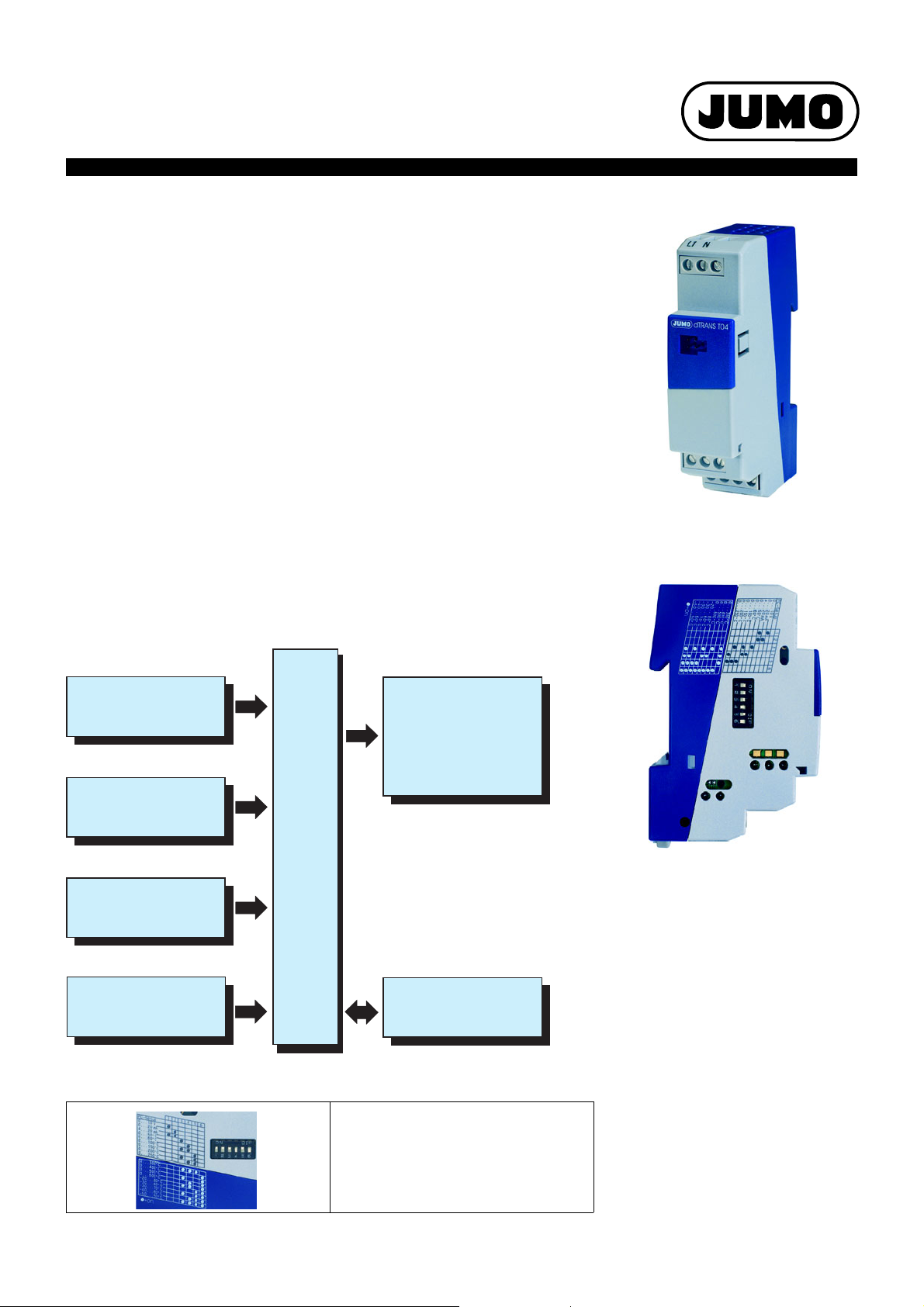
JUMO dTRANS T04
Four-wire Transmitter, settable via
DIP switch/PC setup program
for connection to Pt100/Pt1000 resistance thermometer
or potentiometer; rail-mounted to EN 60715
Brief description
These transmitters are designed for industrial applications and are used to measure the
temperature or resistance through a Pt100 or Pt1000 resistance sensor or potentiometer in
2-wire or 3-wire circuit connection.
The 0 — 20 mA, 4 — 20 mA or 0 — 10 V output signal is available linear with temperature/
resistance. The continuous analog signal path enables a fast reaction of the output to a
temperature change (analog continuous measurement instead of digital sampling rate).
This results in a low-noise output signal that is immune to interference. High precision, even
with small ranges, is ensured by the range-specific gain adjustment.
The transmitter can be set either on the instrument itself, via DIP switch, or through the PC
setup program.
Data Sheet 70.7040
dTRANS T04
Type 707040/...
Page 1/8
Block structure
Controls
Key features
k Measuring range selectable via DIP
switch or through the PC setup
program
k Choice of signal output:
0—10V, 0—20mA or 4—20mA
k Fast response, thanks to
continuous analog measurement
The chosen measuring range and
output response can be set via DIP switch.
Using the PC setup program,
additional ranges and parameters
are configurable.
k Low-noise current signal,
immune to interference
k Electrical isolation
between input, output / mains supply
k Current/ voltage output
2009-03-06/00443951
Page 2
Data Sheet 70.7040JUMO GmbH & Co. KG • 36035 Fulda, Germany Page 2/8
Technical data
Input
Measurement input Pt100 EN 60751 Pt1000 EN 60751 Potentiometer
Range limits -200 to +850°C -200 to +850°C 0 — 11000Ω
Connection circuit 2- and 3-wire circuit
Configuration through DIP switch or using the PC setup program
Shortest span 25°C 25°C 250Ω
Largest span 1050°C 1050°C 11000Ω
Range start
for shortest span -50°C to +20°C -50°C to +20°C 0 — 500Ω
Range start
for other spans see range organization on Page 5 and Page 6
Unit °C (°F settable through the PC
setup program)
Sensor lead resistance
for 3-wire connection ≤ 11Ω per conductor
Sensor lead resistance
for 2-wire connection
Sensor current ≤ 0.5mA ≤ 0.1mA ≤ 0.1mA
Sampling rate continuous measurement (analog signal path)
°C (°F settable through the PC
setup program)
factory-set: 0Ω lead resistance,
adjustable through the PC setup program
Ω
Output
Measurement input Pt100 EN 60751 Pt1000 EN 60751 Potentiometer
Output signal
- current:
- voltage:
selectable through DIP switch or PC setup program
proportional DC current 0 — 20mA or 4 — 20mA
DC voltage 0 — 10V
Transfer characteristic
- for resistance thermometer:
- for potentiometer:
Transfer accuracy ≤ ± 0.1%
Residual ripple ≤ ± 0.2%
linear with temperature
linear with resistance
1
1
Burden (with current output) ≤ 750Ω
Burden error ≤ ± 0.01% / 100Ω
1
Current limiting > 21.6mA — < 28mA (24mA typical)
Load (with voltage output) ≥ 10kΩ
Load error ≤ ± 0.1%
1
Voltage limiting > 11V — < 14V (12V typical)
Settling time on a temperature change ≤ 40msec
Settling time after switch-on or reset ≤ 200msec
Calibration conditions 230V AC or 24V DC (depending on the supply) at 23°C (± 5°C)
Calibration accuracy ≤ ± 0.3%
1,2
or ≤ ± 0.3°C
Supply voltage error ≤ ± 0.05%
1
All data refer to the range end value 10V or 20 mA
2
The larger value applies
2
≤ ± 0.3%
1,2
or ≤ ± 0.3°C
2
1
≤ ± 0.3%
Measuring circuit monitoring
Underrange:
- current output 4 — 20mA
- current output 0 — 20mA
- voltage output 0 — 10V
Overrange
- current output 4 — 20mA
- current output 0 — 20mA
- voltage output 0 — 10V
Probe short-circuit:
- current output 4 — 20mA
- current output 0 — 20mA
- voltage output 0 — 10V
rising to > 21.6mA — < 28mA (24 mA typical)
rising to > 21.6mA — < 28mA (24 mA typical)
rising to > 11V — < 14V (12V typical)
≥ 1.5mA — ≤ 3.6mA (2mA typical)
falling to ≤ 3.6mA
< 0mA (-0.05mA typical)
< 0V -0.6V typical)
< 0mA (-0.05mA typical)
< 0V (-0.6V typical)
1
2009-03-06/00443951
Page 3
Data Sheet 70.7040JUMO GmbH & Co. KG • 36035 Fulda, Germany Page 3/8
Probe and lead break:
- current output 4 — 20mA
- current output 0 — 20mA
- voltage output 0 — 10V
positive signal: > 21.6mA — < 28mA (24mA typical)
negative signal: ≥ 1.5mA — ≤ 3.6mA (2mA typical)
positive signal: > 21.6mA — < 28mA (24mA typical)
negative signal: < 0mA (-0.05mA typical)
positive signal: > 11V — < 14 V (12 V typical)
Signal is configurable.
negative signal: < 0V (-0.6V typical)
Electrical data
Supply voltage 110 — 240V AC +10/-15%, 48 — 63Hz 20 — 53V AC/DC, 48 — 63Hz
Power consumption 4VA 3VA
Electrical safety to EN 61010, Part 1
for switching cabinet mounting to EN 50178
Test voltage 3700V 500V
Electrical isolation The supply is electrically isolated from the
input and the output. There is no electrical
overvoltage category III,
pollution degree 2,
isolation between input, output
and setup connector.
for operation with SELV/PELV circuits
The supply is electrically isolated from the
input and the output. There is no electrical
to EN 61010, Part 1
protection class III,
isolation between input, output
and setup connector.
Environmental influences
Operating temperature range -25 to +55°C
Storage temperature range -40 to +90°C
Storage temperature humidity rel. humidity ≤ 85%, no condensation
Temperature error ≤ ± 0.01% / °C
Climatic conditions EN 60721-3-3 3K3
rel. humidity ≤
Vibration strength according to GL Characteristic 2
EMC
- interference emission
- immunity to interference
IP enclosure protection IP20 to EN 60529
1
All data refer to the range end value 10V or 20 mA
85% annual average, no condensation
EN 61326
Class B
to industrial requirements
1
Housing
Material polycarbonate
Flammability class UL 94 V0
Dimensions (W x H x D) 22.5 x 93.5 x 60mm
Screw terminal 2,5mm² wire cross-section / 2.5mm wire dia.
Mounting on 35mm x 7.5mm DIN rail to EN 60715 A.1,
for installation in control cabinets
Operating position unrestricted
Weight approx. 100g
2009-03-06/00443951
Page 4

Data Sheet 70.7040JUMO GmbH & Co. KG • 36035 Fulda, Germany Page 4/8
PC setup program
The PC setup program is used for configuration and fine adjustment of the transmitter from a PC (e.g. when the sensor drifts). Connection
is through the PC interface with TTL/RS232 converter and adapter and the setup interface of the transmitter. In order to configure the
transmitter, it must be connected to the supply.
Configurable parameters
- TAG number (14 characters)
- response to probe and cable break
- range start, range end
- output signal 0(4) — 20mA or 0 — 10V
- lead resistance for 2-wire circuit
Fine adjustment
Fine adjustment means correction of the output signal of a configured transmitter; systematic errors such as those caused by an
unsuitable probe mounting can be compensated. The signal can be adjusted in the range ±0.2mA for current output and ±0.1V for
voltage output. Fine adjustment can only be carried out through the setup program.
Hardware and software requirements
The following hardware and software requirements must be met for installing and operating the PC setup program:
- IBM-PC or compatible PC with Pentium processor or higher
- 64 MB main memory
- 15MB available on hard disk
-CD-ROM drive
- 1 free serial interface
- Win 98, ME or Win NT4.0, 2000, XP
DIP switch configuration
Function or measuring range
for Pt100 and Pt1000
PC setup
Output 0 — 10V Output 0 — 10V
Output 0 — 20mA Output 0 — 20 mA
Output 4 — 20mA Output 4 — 20 mA
Range 0 to 50°C Range 0 — 500Ω
Range 0 to 60°C Range 0 — 1kΩ
Range 0 to 100°C Range 0 — 2kΩ
Range 0 to 150°C Range 0 — 3kΩ
Range 0 to 200°C Range 0 — 4kΩ
Range 0 to 250°C Range 0 — 5kΩ
Range 0 to 300°C Range 0 — 6kΩ
Range 0 to 400°C Range 0 — 7kΩ
Range 0 to 500°C Range 0 — 8kΩ
Range 0 to 600°C Range 0 — 9kΩ
Range -20 to +80°C Range 0 — 10kΩ
Range -30 to +60°C Range 0 — 11kΩ
Range -30 to +70°C
Range -40 to +60°C
Range -50 to +50°C
1
When configuring through the PC setup program, the input and output must be configured from the PC.
1
Function or measuring range
for potentiometer
PC setup
1
DIP switch
123456
•
•
••
•
•
••
•
••
••
•••
•
••
••
•• •
••
•••
•••
••••
• = on
2009-03-06/00443951
Page 5

Data Sheet 70.7040JUMO GmbH & Co. KG • 36035 Fulda, Germany Page 5/8
Measuring range span °C
Measuring range start °C
Measuring range organization (resistance thermometer)
All the possible range-start values in relation to the range span are contained within the gray area.
range span = range end – range start
Example: range start = -50°C, range end = 275°C
range span = range end – range start = 275°C - (-50°C) = 325°C
Please note: When selecting the range start, make sure it lies within the gray area.
2009-03-06/00443951
Page 6
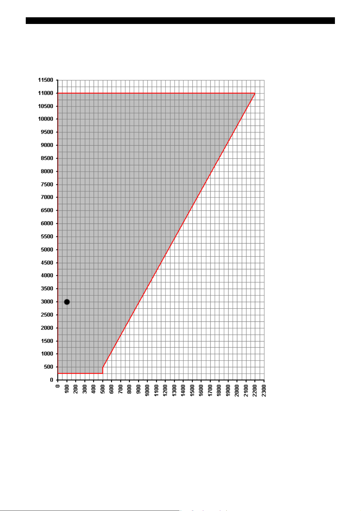
Measuring range organization (potentiometer)
Measuring range start Ω
Measuring range span
Data Sheet 70.7040JUMO GmbH & Co. KG • 36035 Fulda, Germany Page 6/8
All the possible range-start values in relation to the range span are contained within the gray area.
range span = range end – range start
Example: range start = 100Ω, range end = 3100Ω
range span = range end – range start = 3100Ω – 100Ω = 3000Ω
Please note: When selecting the range start, make sure it lies within the gray area.
2009-03-06/00443951
Page 7

Connection diagram
Voltage output 0 10 V
Current output 0(4) 20 mA
4 (+)
5 (-)
6 (+)
7 (-)
Potentiometer
3-wire 2-wire
circuit circuit
Resistance thermometer
3-wire 2-wire
circuit circuit
Setup interface
N (L-)
L1 (L+)
1
2
3
1
2
3
1
2
3
3
1
2
Data Sheet 70.7040JUMO GmbH & Co. KG • 36035 Fulda, Germany Page 7/8
Dimensions
2009-03-06/00443951
Page 8

Order details: JUMO dTRANS T04
Four-wire transmitter, settable via DIP switch/PC setup program
Data Sheet 70.7040JUMO GmbH & Co. KG • 36035 Fulda, Germany Page 8/8
(1)
Basic version
707040/1 dTRANS T04 for Pt100 resistance thermometer
707040/2
707040/3 dTRANS T04 for potentiometer
xx
x
xxx
xxx
xxx
888 factory-set2 (3-wire circuit, 0 to 100°C)
888 factory-set2 (3-wire circuit, 0 — 1kΩ)
999 configuration to customer specification (please specify in plain text)
888 factory-set (0 — 20mA)
999 setting to customer specification (please specify in plain text)
xxx
xxx
Order code --Order example 707040/1 - 888 - 888 - 23
1
It is not possible to switch between the sensor types.
2
Additional measuring ranges are selectable via DIP switch or PC setup program (see Page 4).
3
Please check whether the required measuring range and output can be set via DIP switch.
dTRANS T04 for Pt1000 resistance thermometer
(2) Input
(3) Output
(4) Supply
22 20 — 53 V AC/DC, 48 — 63 Hz
23 110 — 240 V AC +10/-15 %, 48 — 63 Hz
(1) (2) (3) (4)
1
In such a case, “factory-set” can be ordered.
3
3
Standard accessory
- Operating Manual
Accessories - Data Sheet 70.9700
Sales No.
- PC setup program, multilingual 70/00448774
- PC interface with TTL/RS232 converter and adapter (socket) 70/00350260
- PC interface with USB/TTL converter, adapter (socket) and adapter (pins) 70/00456352
2009-03-06/00443951
 Loading...