

Page 1
JUMO GmbH & Co. KG
dTRANS T03 T
Type 707032/...
dTRANS T03 TU
Type 707034/...
dTRANS T03 BU
Type 707033/...
dTRANS T03 J
Type 707030/...
dTRANS T03 B
Type 707031/...
Delivery address:Mackenrodtstraße 14,
Postal address:
Phone: +49 661 6003-0
Fax: +49 661 6003-607
e-mail: mail@jumo.net
Internet: www.jumo.net
36039 Fulda, Germany
36035 Fulda, Germany
JUMO Instrument Co. Ltd.
JUMO House
Temple Bank, Riverway
Harlow, Essex CM20 2DY, UK
Phone: +44 1279 635533
Fax: +44 1279 635262
e-mail: sales@jumo.co.uk
Internet: www.jumo.co.uk
JUMO PROCESS CONTROL INC.
885 Fox Chase, Suite 103
Coatesville PA 19320, USA
Phone: 610-380-8002
1-800-554-JUMO
Fax: 610-380-8009
e-mail: info@JumoUSA.com
Internet: www.JumoUSA.com
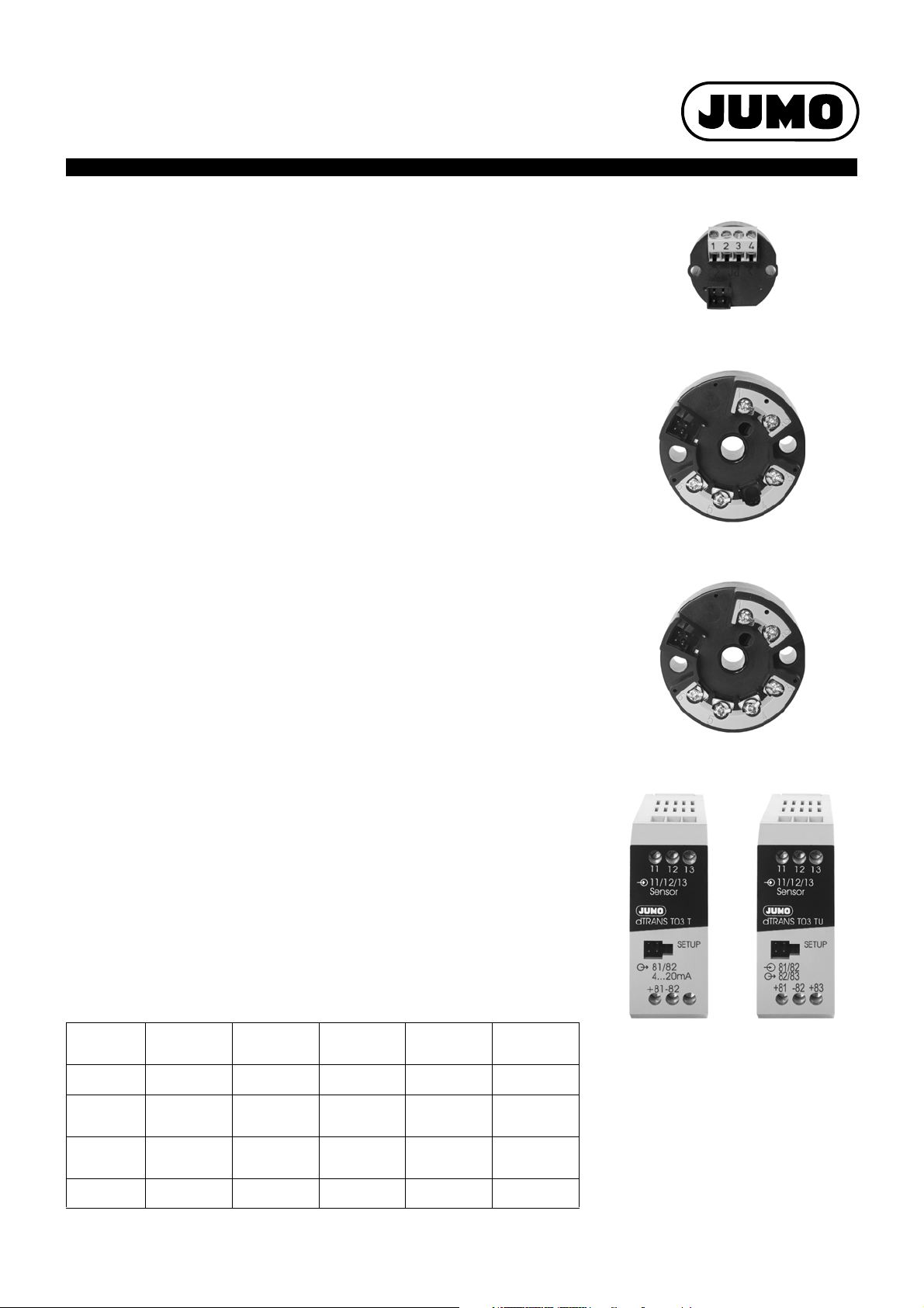
JUMO dTRANS T03 J, B, T
Analog 2-wire transmitter
with digital adjustment
JUMO dTRANS T03 BU, TU
Analog 3-wire transmitter
with digital adjustment
for connection to Pt100 resistance thermometers
for installation in: - terminal head Form B to DIN 43729
- terminal head Form J
for mounting on: - rail according to EN 60715
Brief description
Data Sheet 707030
Page 1/10
These transmitters are designed for industrial applications and are used to measure the
temperature through Pt100 resistance thermometers in 2-wire or 3-wire circuit
connections (Pt500 or Pt1000 linearization upon request).
The 4
— 20 mA or 0 — 10 V output signal is linear with temperature.
The continuous analog signal path enables an extremely fast reaction time of the output
to a change in temperature (continuous analog measurement instead of digital sampling
rate), resulting in a low-noise output signal that is insensitive to interference. A very high
degree of precision - even with small ranges - is ensured thanks to the range-specific gain
adjustment.
Digital communication allows the transmitter to be adapted to the measurement task
(range, probe break and fine calibration).
Two versions are available to suit specific requirements:
Instruments with basic type extension 880/990 (adjustable)
The transmitters are calibrated for a fixed range but can, at any time, be calibrated for a
different range through the setup program.
Instruments with basic type extension 881/991 (configurable)
The required range can be configured through the setup program, without sensor
simulation and measurement.
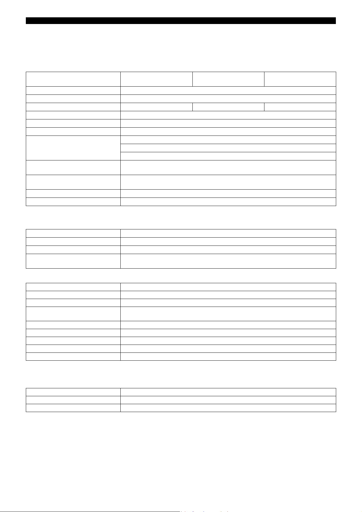
Overview of function
dTRANS T03 J
Type 707030/...
dTRANS T03 B
Type 707031/...
dTRANS T03 T
Type 707032/...
dTRANS T03 BU
Type 707033/...
dTRANS T03 TU
Type 707034/...
Input Pt100 Pt100 Pt100 Pt100 Pt100
Connection
circuit
Mounting terminal head
Output 4—20mA 4—20mA 4—20mA 0—10V 0—10V
2013-07-31/00391028
2-wire 2-wire or 3-wire 2-wire or 3-wire 2-wire or 3-wire 2-wire or 3-wire
Form J
terminal head
Form B
mounting rail terminal head
Form B
mounting rail
Page 2
Data Sheet 707030JUMO GmbH & Co. KG • 36035 Fulda, Germany Page 2/10
Technical data for 2-wire transmitter
(Types 707030/..., 707031/... and 707032/...)
Input for resistance thermometer
dTRANS T03 J
Type 707030/...
Measurement input Pt100 (EN 60751)
Range limits -200 to +850°C
Connection circuit 2-wire circuit 2-wire or 3-wire circuit 2-wire or 3-wire circuit
Smallest span 25°C
Largest span 1050°C
Unit measuring range configuration in °C or °F
Zero shift for spans < 75°C fixed zero: -40 °C, -20 °C, 0°C, 20°C, 40°C
for spans > 75°C: see “Range organization” on page 7
Sensor lead resistance
for 3-wire connection 11 per conductor
Sensor lead resistance
for 2-wire connection
settable through setup program
Sensor current 0.5mA
Sampling rate continuous measurement because of analog signal path
a
-30°C, -10°C, 0°C, 10°C, 30°C available upon request
dTRANS T03 B
Type 707031/...
for span 75°C: ±50°C
factory-set:0lead resistance
dTRANS T03 T
Type 707032/...
a
Measurement circuit monitoring to NAMUR recommendation NE43
Underrange falling to 3.6mA
Overrange rising to 22mA to 28mA (typically 24mA)
Probe short-circuit 3.6mA
Probe and lead break positive: 22mA to 28mA (typically 24mA)
negative: 3.6mA
Output
Output signal proportional DC current 4 — 20mA
Transfer characteristic linear with temperature
Transfer accuracy ± 0.1%
a
Damping of ripple
on supply voltage > 40dB
Burden (Rb) Rb = (Ub - 7.5V) divided by 22mA
Burden error ± 0.02% per 100
a
Settling time on a temperature change 10msec
Calibration conditions 24V DC at approx. 22°C
Calibration/configuration accuracy ± 0.2%
a
All details refer to the range-end value 20mA
b
The larger value applies
c
If the measuring range end value > 600 °C then the calibration or configuration accuracy is ± 0.4 %
a, b, c
or ± 0.2°C
b
Supply voltage
Supply voltage (Ub) 7.5 — 30V DC
Reverse polarity protection yes
Supply voltage error ± 0.01% per V deviation from 24V
a
All details refer to the range-end value 20mA
a
2013-07-31/00391028
Page 3
Data Sheet 707030JUMO GmbH & Co. KG • 36035 Fulda, Germany Page 3/10
2-wire
transmitter
RecorderIndicatorController
Supply unit
7.5 —30 V DC
=
-
4 — 20 mA
- -+ ++
+
-
+
-
_
~
RecorderIndicatorController
Supply isolator
=
=
~
2-wire
transmitter
+
-
+
-
4—20 mA
+
-
+
4—20 mA / 0—20 mA
+ +- - -
L1 N
+
-
+
0—10 V
+ +- - -
=
Ambient conditions
dTRANS T03 J
Type 707030/...
dTRANS T03 B
Type 707031/...
dTRANS T03 T
Type 707032/...
Operating temperature range -50 to +85°C -50 to +85°C -25 to +70°C
Storage temperature range -50 to +85°C -50 to +85°C -40 to +85 °C
Temperature error ± 0.01% per °C deviation from 22°C
a
Climatic conditions rel. humidity 95% annual mean, no condensation
Vibration strength to GL Characteristic 2 to GL Characteristic 2 EMC
- interference emission
- immunity to interference
EN 61326
Class B
to industrial requirements
IP enclosure protection
- in terminal head / open mounting
- on C-rail
a
All details refer to the range-end value 20mA
IP54 / IP00
-
IP54 / IP00
-
-
IP20
Housing
Type 707030/... Type 707031/... Type 707032/...
Material polycarbonate (encapsulated) polycarbonate (encapsulated) polycarbonate
Screw terminal 1.5mm²;
max. torque 0.15Nm
Mounting inside terminal head Form J inside terminal head Form B
1.75mm²;
max. torque 0.6Nm
DIN 43729;
in surface-mounting case
(upon request);
in switch cabinet
2.5mm²;
max. torque 0.6Nm
on C-rail
35mm × 7.5mm (EN 60715);
on C-rail
15mm (EN 60715);
on G-rail (EN 60715)
(fixing bracket is required)
use only original accessories for mounting!
Operating position unrestricted
Weight approx. 12g approx. 45g approx. 70g
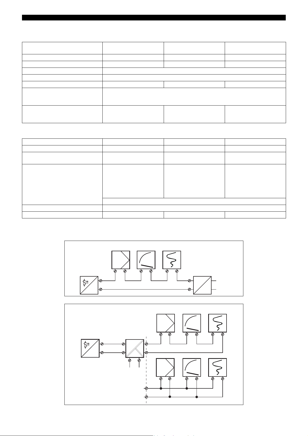
System diagrams for 2-wire transmitter
Connection example with supply unit
Connection example with supply isolator
2013-07-31/00391028
Page 4

Data Sheet 707030JUMO GmbH & Co. KG • 36035 Fulda, Germany Page 4/10
Technical data for 3-wire transmitter
(Types 707033/..., and 707034/...)
Input for resistance thermometer
dTRANS T03 BU
Type 707033/...
Measurement input Pt100 (EN 60751)
Range limits -200 to +850°C
Connection circuit 2-wire or 3-wire circuit
Smallest span 25°C
Largest span 1050°C
Unit measuring range configuration in °C or °F
Zero shift for spans < 75°C fixed zero: -40°C, -20°C, 0°C, 20 °C, 40°C
for span 75°C: ±50 °C
for spans > 75°C: see “Range organization” on page 7
Sensor lead resistance
for 3-wire connection 11 per conductor
Sensor lead resistance
for 2-wire connection
factory-set: 0 lead resistance,
settable through setup program
Sensor current 0.5mA
Sampling rate continuous measurement because of analog signal path
dTRANS T03 TU
Type 707034/...
Measurement circuit monitoring to NAMUR recommendation NE43
Underrange 0V
Overrange rising to 11V to 14V (typically 12 V)
Probe short-circuit 0V
Probe and lead break positive: rising to 11V to 14V (typically 12V)
negative: 0V
Output
Output signal DC voltage 0 — 10V
Transfer characteristic linear with temperature
Transfer accuracy ± 0.2%
a
Damping of ripple
on supply voltage > 40dB
Load 10k
Load error ± 0.1%
a
Settling time on a temperature change 10msec
Calibration conditions 24V DC at approx. 22°C
Calibration/configuration accuracy ± 0.2%
a
All details refer to the range-end value 10 V
b
The larger value applies
c
If the measuring range end value > 600 °C then the calibration or configuration accuracy is ± 0.4 %
a, b, c
or ± 0.2°C
b
Supply voltage
Supply voltage (Ub) 15 — 30V DC
Reverse polarity protection yes
Supply voltage error ± 0.01% per V deviation from 24V
a
All details refer to the range-end value 10 V
a
2013-07-31/00391028
Page 5

Data Sheet 707030JUMO GmbH & Co. KG • 36035 Fulda, Germany Page 5/10
Supply unit
=
~
+
-
-
+
L1
N
=
+
0 — 10 V
+ +- - -
+
0 — 10 V
RecorderIndicatorController
3-wire
transmitter
Ambient conditions
dTRANS T03 BU
Type 707033/...
dTRANS T03 TU
Type 707034/...
Operating temperature range -40 to +85°C -25 to +70°C
Storage temperature range -40 to +85°C
Temperature error ± 0.01% per °C deviation from 22°C
a
Climatic conditions rel. humidity 95% annual mean, no condensation
Vibration strength to GL Characteristic 2 EMC
- interference emission
- immunity to interference
EN 61326
Class B
to industrial requirements
IP enclosure protection
- in terminal head / open mounting
- on C-rail
a
All details refer to the range-end value 10 V
IP54 / IP00
-
-
IP20
Housing
Type 707033/... Type 707034/...
Material polycarbonate (encapsulated) polycarbonate
Screw terminal 1.75mm²;
max. torque 0.6Nm
Mounting inside terminal head Form B
DIN 43729;
in surface-mounting case
(upon request);
in switch cabinet
35mm × 7.5mm (EN 60715);
2.5mm²;
max. torque 0.6Nm
on C-rail
on C-rail
15mm (EN 60715);
on G-rail (EN 60715)
(fixing bracket is required)
use only original accessories for mounting!
Operating position unrestricted
Weight approx. 45g approx. 70g
System diagram for 3-wire transmitter
Connection example
2013-07-31/00391028
Page 6

Data Sheet 707030JUMO GmbH & Co. KG • 36035 Fulda, Germany Page 6/10
USB/SPI
+
-
+
-
-
+
Supply voltage
7.5 — 30V / 25mADC
Indicator
4 — 20mA
Precision
decade resistor
Supply voltage
15 — 30V DC
Indicator
0 — 10V
Precision
decade resistor
dTRANS T03 BU
dTRANS T03 B
USB
USB/SPI converter
Adapter
USB/SPI
+
-
+
-
Supply voltage
7.5 — 30V / 25mADC
Supply voltage
15 — 30V DC
dTRANS T03 BU
dTRANS T03 B
USB
USB/SPI converter
Adapter
Setup program (for all types)
The setup program is available for calibrating/configuring the transmitter from a PC.
Connection is through a USB/SPI-interface (including adapter) and the setup interface of the transmitter. In order to calibrate/configure
the transmitter, it has to be connected to the supply voltage. If no power supply or supply isolator is available, Types 707030/..., 707031/
... and 707032/... can be supplied from a 9V block battery.
Adjustable/configurable parameters
- TAG number (8 characters)
- response to probe and cable break
- range start, range end
- lead resistance for 2-wire circuit
- measuring range configuration in °C or °F
Fine calibration
Fine calibration means adjustment of the output signal of a calibrated/configured transmitter. Errors due to the system (such as an
unfavorable probe installation) can be compensated. The signal can be adjusted in the range ±0.2mA for current output and ±0.1V for
voltage output. Negative output voltages are not possible with voltage output. Fine calibration can only be carried out through the setup
program.
Hardware and software requirements
The following hardware and software requirements have to be met for installing and operating the setup program:
- IBM-PC or compatible PC
- 256 MB main memory
- 50 MB available on hard disk
-CD-ROM drive
- 1 USB interface
- Windows 2000, XP, Vista, Windows 7 (32 Bit and 64 Bit)
Connection layout for calibrating/configuring the dTRANS T03 B and BU
Calibration
(basic type extension 880/990)
Configuration
(basic type extension 881/991)
2013-07-31/00391028
Page 7

Range organization
Data Sheet 707030JUMO GmbH & Co. KG • 36035 Fulda, Germany Page 7/10
All the possible range-start values in relation to the range span are contained within the gray area.
range span = range end – range start
Example: range start = -50°C, range end = 250 °C
range span = range end – range start = 250°C - (-50°C) = 300°C
Caution: When selecting the range start, make sure it lies within the gray area.
Please note: for spans smaller than 75°C, the only permissible start values are:
-40°C, -20°C, 0°C, +20°C and +40°C.
2013-07-31/00391028
Page 8

Connection diagram for 2-wire transmitter
Setup
Setup
R
B
Ub7.5V–
22mA
-------------------------
=
R
B
Ub7.5V–
22mA
-------------------------
=
dTRANS T03 J - Type 707030/...
Connection for Terminal assignments
Supply voltage
7.5 — 30V DC
Current output
4—20mA
Analog inputs
Resistance
thermometer in
2-wire circuit
dTRANS T03 B - Type 707031/...
Connection for Terminal assignments
Supply voltage
7.5 — 30V DC
Current output
4—20mA
Data Sheet 707030JUMO GmbH & Co. KG • 36035 Fulda, Germany Page 8/10
Ub7.5V–
-------------------------
R
=
B
+1
-2
3
R
= burden resistance
B
U
= supply voltage
b
standard is R
22mA
= 0
L
4
+1
-2
R
= burden resistance
B
U
= supply voltage
b
dTRANS T03 T - Type 707032/...
Analog inputs
Resistance
thermometer in
2-wire circuit
Resistance
thermometer in
3-wire circuit
3
5
6
3
5
6
standard is R
R
11
L
= lead resistance
R
L
L
per conductor
= 0
Connection for Terminal assignments
Supply voltage
7.5 — 30V DC
+81
Current output
4—20mA
-82
R
= burden resistance
B
U
= supply voltage
b
Analog inputs
Resistance
thermometer in
2-wire circuit
Resistance
thermometer in
3-wire circuit
11
12
13
11
12
13
standard is R
R
11
L
= lead resistance
R
L
L
per conductor
= 0
2013-07-31/00391028
Page 9

Connection diagram for 3-wire transmitter
Setup
12
+–3+
54
J
6
54
J
6
81 82
+–83+
Ø44
+1
0
21
+1
0
Ø7
Ø5
C-rail 35mm x 7.5mm EN 60715C-rail 35mm x 7.5mm EN 60715
C-rail 15mm EN 60715C-rail
15mm EN 60715
G-rail EN 60715G-rail
EN 60715
dTRANS T03 BU - Type 707033/...
Connection for Terminal assignments
Supply voltage
15 — 30V DC
Data Sheet 707030JUMO GmbH & Co. KG • 36035 Fulda, Germany Page 9/10
+1
-2
dTRANS T03 TU - Type 707034/...
Voltage output
-2+3load 10k
0—10V
Analog inputs
Resistance
thermometer in
2-wire circuit
Resistance
thermometer in
3-wire circuit
4
5
6
4
5
6
standard is R
R
11
L
= lead resistance
R
L
L
per conductor
= 0
Connection for Terminal assignments
Supply voltage
15 — 30V DC
Voltage output
0—10V
+81
-82
-82
+83
load 10k
Analog inputs
Resistance
thermometer in
2-wire circuit
11
12
13
standard is R
= 0
L
R
Resistance
thermometer in
3-wire circuit
11
12
13
11
L
= lead resistance
R
L
per conductor
Dimensions
dTRANS T03 J dTRANS T03 B and dTRANS T03 BU
dTRANS T03 T and dTRANS T03 TU
2013-07-31/00391028
Page 10

Order details: JUMO dTRANS T03
Analog transmitter with digital adjustment
(1) Basic version
dTRANS T03 J
707030
analog 2-wire transmitter
for installation in terminal head Form J
(2-wire circuit only)
Data Sheet 707030JUMO GmbH & Co. KG • 36035 Fulda, Germany Page 10/10
xxxxx
xxxxx
xxxxx
xxxxx
xxxx
xxxxx
xxx
xx
xxxxx
xx
x
707031
707032
analog 2-wire transmitter
for installation in terminal head Form B
dTRANS T03 T
analog 2-wire transmitter
for rail mounting
dTRANS T03 B
707033
dTRANS T03 BU
analog 3-wire transmitter
for installation in terminal head Form B
dTRANS T03 TU
707034
analog 3-wire transmitter
for rail mounting
(2) Basic type extensions
880 adjustable
881 configurable
990 adjustable
991 configurable
a
a
b
b
(3) Input
001 Pt100 in 3-wire circuit
003 Pt100 in 2-wire circuit
c
c
(4) Output
005 4 — 20 mA
040 0 — 10 V
(5) Extra codes
000 none
243 transmitter in surface-mounting case
950 railway application
d
Order code /--/
(1) (2) (3) (4) (5)
Order example 707031 / 880 - 001 - 005 / 243
a
factory-set (probe break: positive; lead resistance: 0
b
setting to customer specification (please specify in plain text)
c
Pt500 or Pt1000 upon request
d
upon request
Standard accessories
- Operating Instructions
- Fixing items
Accessories
- Setup program, multilingual
- PC interface with USB/SPI converter and adapter (socket), part no. 00553388
- Fixing bracket for mounting Type 707031/... and Type 707033/... on mounting rail, part no. 00352463
- Supply units 1- way and 4-way (Data Sheet 707500)
2013-07-31/00391028
 Loading...