

Page 1
JUMO GmbH & Co. KG
Delivery address: Mackenrodtstraße 14
36039 Fulda, Germany
Postal address:
36035 Fulda, Germany
Phone: +49 661 6003-0
Fax: +49 661 6003-607
E-mail: mail@jumo.net
Internet: www.jumo.net
JUMO Instrument Co. Ltd.
JUMO House
Temple Bank, Riverway
Harlow, Essex CM20 2DY, UK
Phone: +44 1279 635533
Fax: +44 1279 635262
E-mail: sales@jumo.co.uk
Internet: www.jumo.co.uk
JUMO Process Control, Inc.
6733 Myers Road
East Syracuse, NY 13057, USA
Phone: 315-437-5866
1-800-554-5866
Fax: 315-437-5860
E-mail: info.us@jumo.net
Internet: www.jumousa.com
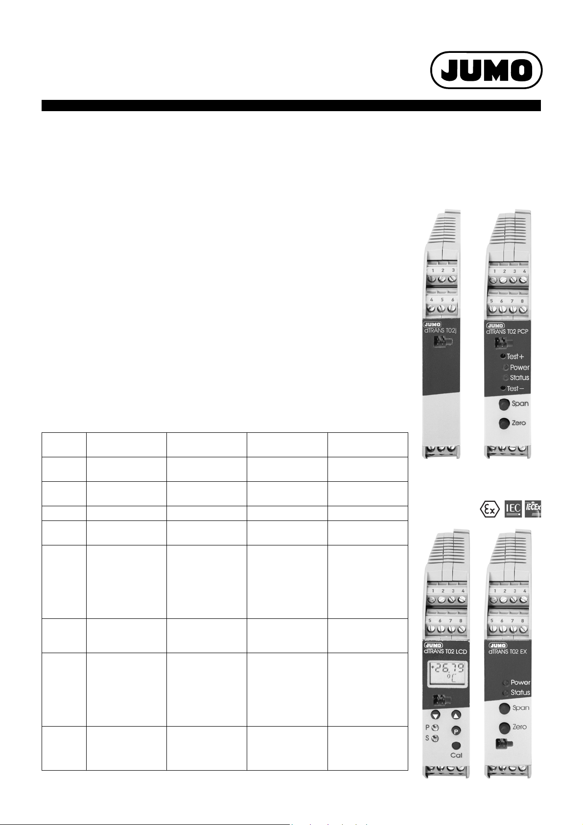
JUMO dTRANS T02
Type 707020/…
Type 707021/…
Type 707022/…
Type 707025/…
Programmable 4-wire Transmitter
(Smart Transmitter)
with isolation of the standard signal
for mounting on DIN rail 35mm x 7.5mm to EN 60715
Brief description
The JUMO dTRANS T02 transmitters incorporate a microprocessor for digital signal processing. Input and output are electrically isolated. They can be mounted on a DIN rail, the
electrical connection is by screw terminals for stranded or solid wire up to 2.5mm² conductor cross-section.
Depending on the type, the 0/4 — 20 mA or 0/2 — 10V output signal is available either linearized (linear with temperature) or inverted (option). The transmitters can be programmed
via the PC setup program, which is supplied as an accessory (sensor type, range, output
action, fine calibration, custom linearization).
On types 707021/... and 707022/... it is possible to additionally program the limits of the
limit comparators, and the frequency output.
Current and voltage outputs are available directly on terminals. No hardware alterations
are required.
Data Sheet 707020
Page 1/12
Overview of function
dTRANS T02j (junior)
Type 707020/...
Housing
width
Display none 2 LEDs 2 LEDs and
Keys none 2 keys 3 keys 2 keys
Supply 24V DC 20— 53VAC/DC
Inputs thermocouple,
Outputs 0/4 — 20mA,
Internal linearization,
Operation fine calibration via
2014-08-08/00379095
17.5mm 22.5mm 22.5mm 22.5mm
resistance
thermometer
(restricted),
potentiometer,
voltage (100mV),
current with ext. shunt
0—10V
customized
linearization
setup program
dTRANS T02 PCP
Type 707021/...
110 — 240V AC
thermocouple,
resistance
thermometer,
resistance transmitter,
potentiometer,
voltage (up to ±10V),
current (up to ±20mA)
0/4 — 20mA,
0/2 — 10V,
2 open-collector
linearization,
customized
linearization,
2 limit comparators or
1 limit comparator and
1 frequency output
fine calibration and
limits via
instrument keys and
setup program
dTRANS T02 LCD
Type 707022/...
LCD display
20 — 53V AC/DC
110 — 240V AC
thermocouple,
resistance
thermometer,
resistance transmitter,
potentiometer,
voltage (up to ±10V),
current (up to ±20mA)
0/4 — 20mA,
0/2 — 10V,
2 open-collector
linearization,
customized
linearization,
2 limit comparators or
1 limit comparator and
1 frequency output
fine calibration and
limits via
instrument keys and
setup program
dTRANS T02 EX
Type 707025/...
2 LEDs
230V AC
20 — 53V AC/DC
thermocouple,
resistance
thermometer,
resistance transmitter,
potentiometer,
voltage (up to ±10V),
current (up to ±20mA)
0/4 — 20mA,
0/2 — 10V
linearization,
customized
linearization
2 limit comparators
(indication only via the
power and status
LEDs)
fine calibration via
instrument keys and
setup program
Page 2
Data Sheet 707020JUMO GmbH & Co. KG • 36035 Fulda, Germany Page 2/12
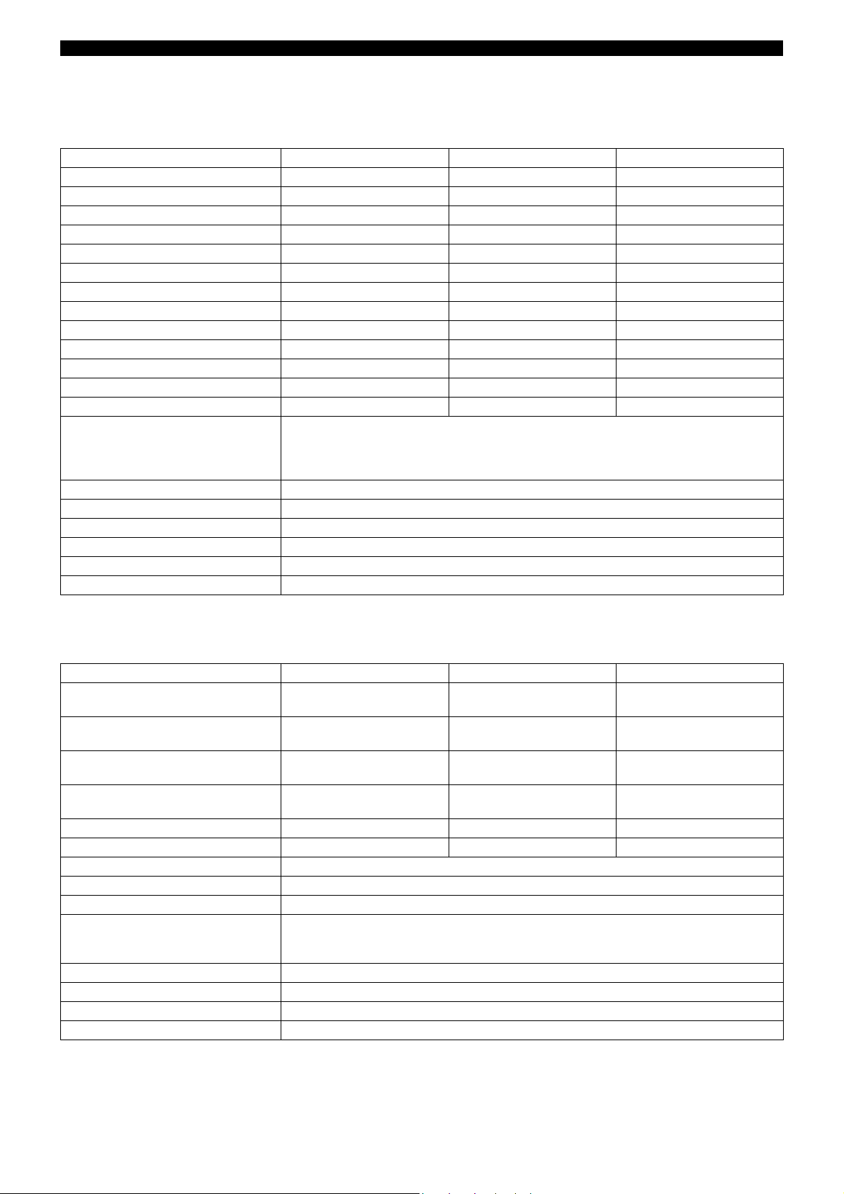
Technical data for type 707020
Input for thermocouple
Designation Range limits Range Accuracy
Fe-Con L DIN 43710 -200 to +900°C -200 to +900°C 0.25%
Fe-Con J EN 60584 -210 to +1200°C -200 to +1200°C 0.25%
Cu-Con U DIN 43710 -200 to +600°C -200 to +600°C 0.25%
Cu-Con T EN 60584 -270 to +400°C -200 to +400°C 0.25%
NiCr-Ni K EN 60584 -270 to +1372°C -150 to +1372°C 0.25%
NiCr-Con E EN 60584 -270 to +1000°C -200 to +1000°C 0.25%
NiCrSi-NiSi N EN 60584 -270 to +1300°C -100 to +1300°C 0.25%
Pt10Rh-Pt S EN 60584 -50 to +1768°C -50 to +1768°C 0.25%
Pt13Rh-Pt R EN 60584 -50 to +1768°C -50 to +1768°C 0.25%
Pt30Rh-Pt6Rh B EN 60584 0 — 1820°C 400 — 1820°C 0.25%
MoRe5-MoRe41 0 — 2000°C 500 — 2000°C 0.25%
W3Re-W25Re D 0 — 2495°C 500 — 2495°C 0.25%
W5Re-W26Re C 0 — 2320°C 500 — 2320 °C 0.25%
Shortest span Type L, J, U, T, K, E, N: 50°C
Type S, R, B: 500 °C
Type MoRe5-MoRe41: 500 °C
Type D , C: 500°C
Range start/end freely programmable range limits
Cold junction Pt100 internal or external cold junction (0 — 80°C is adjustable)
Cold junction accuracy ± 1°C
Sampling rate > 1 measurement per second
Input filter 1st order digital filter; filter constant adjustable from 0 to 125sec
Special features also programmable in °F; input isolated from output
a
The accuracy refers to the maximum range span.
For small ranges, as well as for short spans, the linearization accuracy is reduced.
a
Input for resistance thermometer
Designation Range limits Range Accuracy
Pt 100 EN 60751 -200 to +850°C -100 to +200°C
-200 to +850°C
Pt 100 JIS -200 to +649°C -100 to +200°C
-200 to +649°C
Pt 500 DIN -200 to +250°C -100 to +200°C
-200 to +250°C
Pt 1000 DIN -200 to +250°C -100 to +200°C
-200 to +250°C
Ni 100 -60 to +180°C -60 to +180°C ±0.8°C
Ni 500, Ni 1000 -60 to +150 °C -60 to +150 °C ±0.8°C
Connection circuit 2-, 3- or 4-wire
Shortest span 20°C
Range start/end freely programmable range limits
Sensor lead resistance
- for 3-, 4-wire connection
- for 2-wire connection
Sensor current 0.6mA
Sampling rate > 1 measurement per second
Input filter 1st order digital filter; filter constant adjustable from 0 to 125sec
Special features also programmable in °F; input isolated from output
meas. resistance + 22 internal lead resistance
11 per conductor
±0.4°C
±0.8°C
±0.4°C
±0.8°C
±0.4°C
±0.8°C
±0.4°C
±0.8°C
2014-08-08/00379095
Page 3
Data Sheet 707020JUMO GmbH & Co. KG • 36035 Fulda, Germany Page 3/12
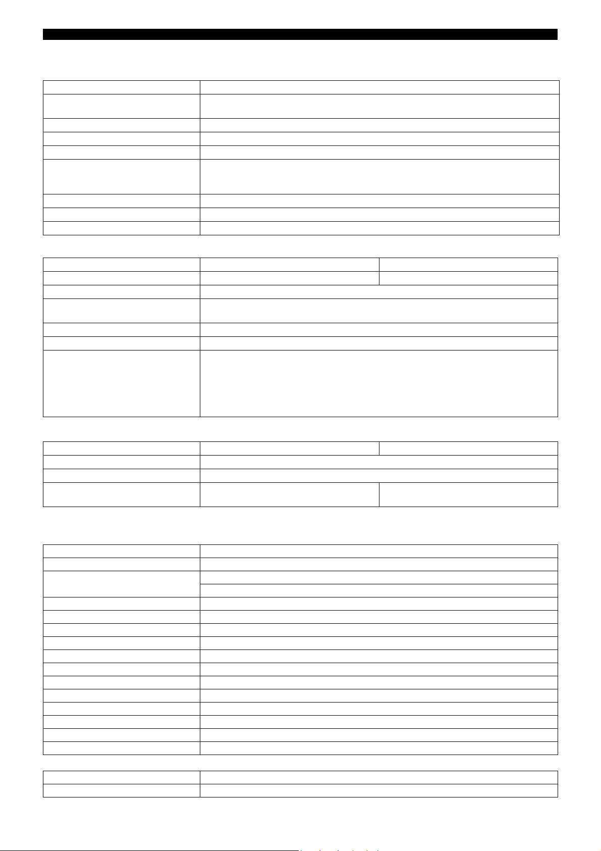
Input for potentiometer
Range Accuracy
up to 400
up to 2000
±500m
±1
Connection circuit 2-, 3- or 4-wire circuit
Shortest span 6
Resistance values freely programmable within the limits in 0.1steps
Sensor lead resistance
- for 3-, 4-wire connection
- for 2-wire connection
meas. resistance + 22 internal lead resistance
11 per conductor
Sampling rate > 1 measurement per second
Input filter 1st order digital filter; filter constant adjustable from 0 to 125sec
Special features also programmable in °F; input isolated from output
Input for DC voltage, DC current
Range Accuracy Input resistance
0 — 100mV ±150VR
> 10 M
IN
Shortest span 5mV
Range start/end freely programmable within the limits
(up to 999mV in 0.1mV steps, above 1V in 1mV steps)
Sampling rate > 1 measurement per second
Input filter 1st order digital filter; filter constant adjustable from 0 to 125sec
Current input The current input can only be implemented in conjunction with an external shunt
(not included in delivery).
Example: a 5shunt results in 0 — 20mA current input, with a programmed
voltage range of 0 — 100mV.
The accuracy corresponds to the voltage input
plus the inaccuracy of the shunt.
Measurement circuit monitoring
Resistance thermometer Thermocouple
Underrange linear drop to 3.8mA or 0 mA (as per NAMUR recommendation 43)
Overrange linear rise to 20.5mA (as per NAMUR recommendation 43)
Probe short-circuit /
0mA or 21.0mA (configurable) 0mA or 21.0mA (configurable)
Probe/lead break
a
Probe short-circuit recognition is not possible for thermocouple
Analog outputs
Current output
Output signal proportional DC current 0 — 20mA or 4 — 20mA programmable
Transfer characteristic linear with temperature
inversion of the output signal
Max. burden 750
Burden error ± 0.02% / 100
1st order digital filter 0 — 125sec configurable
Step response 0 — 100 % 2sec (with filter constant 0sec)
Switch-on delay 5sec (correct measurement after connecting the supply voltage)
Voltage output
Output range 0 — 10V
Accuracy ± 5mV
Linearity error ± 2mV
Load resistance 2k
Load error ± 15mV
Ripple ± 1% referred to 10V, 0 — 90kHz
Custom linearization
Number of calibration points 40 max.
Interpolation linear
a
2014-08-08/00379095
Page 4
Data Sheet 707020JUMO GmbH & Co. KG • 36035 Fulda, Germany Page 4/12
Electrical data
Supply voltage 24V DC +10%/-15%
Power consumption 1W
Supply voltage error ± 0.01% per V deviation from 24V
Test voltage to DIN 61010, Part 1
510V/50Hz, 1min
Isolation
- between input and output
- between input and mains supply
- between output and mains supply
- between input and setup plug
no isolation between input and setup plug
50V
50V
50V
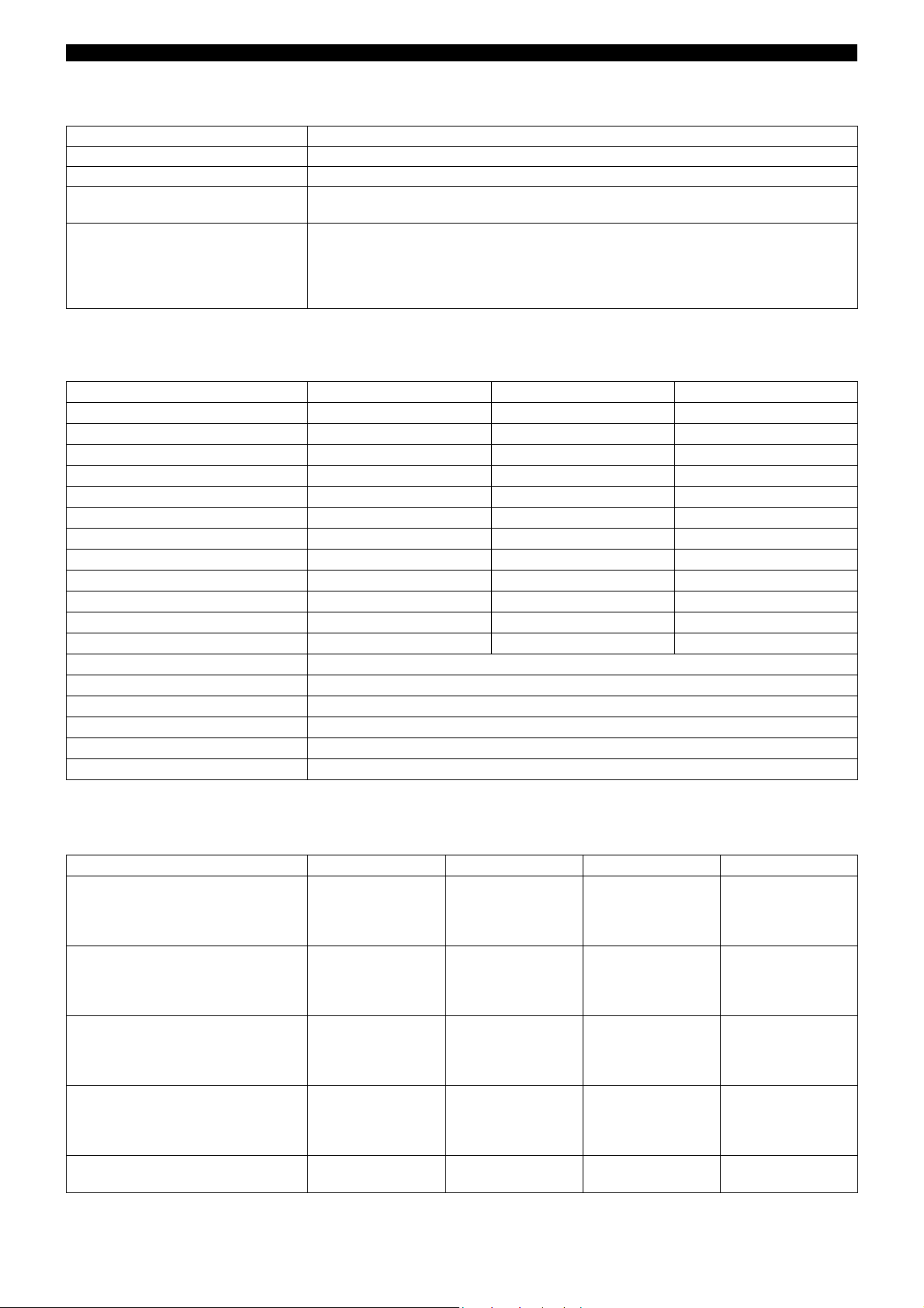
Technical data type 707021/..., type 707022/... and type 707025/...
Input for thermocouple
Designation Range limits Range Accuracy
Fe-Con L DIN 43710 -200 to +900°C -200 to +900°C 0.1% above -150°C
Fe-Con J EN 60584 -210 to +1200°C -200 to +1200°C 0.1% above -100°C
Cu-Con U DIN 43710 -200 to +600°C -200 to +600°C 0.1% above -100°C
Cu-Con T EN 60584 -270 to +400°C -200 to +400°C 0.1% above -100°C
NiCr-Ni K EN 60584 -270 to +1372°C -200 to +1372°C 0.1% above -60°C
NiCr-Con E EN 60584 -270 to +1000°C -200 to +1000°C 0.1% above -60°C
NiCrSi-NiSi N EN 60584 -270 to +1300°C -100 to +1300 °C 0.1% above -80°C
Pt10Rh-Pt S EN 60584 -50 to +1768°C -50 to +1768°C 0.15% above 0°C
Pt13Rh-Pt R EN 60584 -50 to +1768°C -50 to +1768°C 0.15% above 0°C
Pt30Rh-Pt6Rh B EN 60584 0 — 1820°C 400 — 1820°C 0.15% above 400°C
W3Re-W25Re D 0 — 2495°C 500 — 2495°C 0.15% above 500°C
W5Re-W26Re C 0 — 2320°C 500 — 2320°C 0.15% above 500°C
Shortest span Type L, J, U, T, K, E, N: 100°C; type S, R, B, D, C: 500°C
Range start/ end freely programmable within the limits in 0.1°C steps
Cold junction Pt100 internal or external cold junction (adjustable from 0 to 100°C)
Cold junction accuracy ± 1°C
Sampling rate 100msec
Special features also programmable in °F; input isolated from output
a
The accuracy refers to the maximum range span.
For small ranges, as well as for short spans, the linearization accuracy is reduced.
a
Input for resistance thermometer
Designation Connection circuit Range limits Range Accuracy
Pt 100 EN 60751 2/3-wire
2/3-wire
4-wire
4-wire
Pt 100 JIS 2/3-wire
2/3-wire
4-wire
4-wire
Pt 500 DIN 2/3-wire
2/3-wire
4-wire
4-wire
Pt 1000 DIN 2/3-wire
2/3-wire
4-wire
4-wire
Ni 100 2/3-wire
4-wire
2014-08-08/00379095
-200 to +850°C -100 to +200°C
-200 to +850°C
-100 to +200°C
-200 to +850°C
-200 to +649°C -100 to +200°C
-200 to +649°C
-100 to +200°C
-200 to +649°C
-200 to +850°C -100 to +200°C
-200 to +850°C
-100 to +200°C
-200 to +850°C
-200 to +850°C -100 to +200°C
-200 to +850°C
-100 to +200°C
-200 to +850°C
-60 to +180°C -60 to +180°C
-60 to +180°C
±0.4°C
±0.8°C
±0.4°C
±0.5°C
±0.4°C
±0.8°C
±0.4°C
±0.5°C
±0.4°C
±0.8°C
±0.4°C
±0.5°C
±0.4°C
±0.8°C
±0.4°C
±0.5°C
±0.8°C
±0.5°C
Page 5

Data Sheet 707020JUMO GmbH & Co. KG • 36035 Fulda, Germany Page 5/12
Designation Connection circuit Range limits Range Accuracy
Ni 500, Ni 1000 2/3-wire
4-wire
-60 to +150°C -60 to +150°C
-60 to +150°C
±0.8°C
±0.5°C
Connection circuit 2-, 3- or 4-wire circuit
Shortest span 15°C
Range start/end freely programmable within the limits in 0.1°C steps
Sensor lead resistance 30 per conductor (for 3- and 4-wire circuit)
15 per conductor (for 2-wire circuit)
Sensor current 0.6mA
Sampling rate 100msec
Input filter 2nd order digital filter; filter constant adjustable from 0 to 20.0sec
Input for resistance transmitter and potentiometer
Range Accuracy
up to 200
up to 400
up to 800
up to 2000
up to 3900
±300m
±600m
±1
±2
±3
Connection circuit resistance transmitter: 3-wire
potentiometer: 2-, 3- or 4-wire
Shortest span 6
Resistance values freely programmable within the limits in 0.1steps
Sensor lead resistance 30 per conductor for 4-wire circuit
15 per conductor for 2- and 3-wire circuit
up to 200 range: 10 per conductor for 2- and 3-wire circuit
Sampling rate 100msec
Input filter 2nd order digital filter; filter constant adjustable from 0 to 20.0sec
Input for DC voltage, DC current
Range Accuracy Input resistance
-25 to +75mV
0 to 100mV
-100 to +100 mV
0 to 200mV
-500 to +500 mV
0to 1V
-1 to +1V
-5 to +5V
0to 10V
-10 to +10V
±100V
±100V
±150V
±150V
±1mV
±1mV
±2mV
±10mV
±10mV
±15mV
R
> 10 M
IN
R
> 10 M
IN
R
> 10 M
IN
R
> 10 M
IN
R
> 10 M
IN
R
> 10 M
IN
R
> 10 M
IN
R
> 0.5 M
IN
R
> 0.5 M
IN
R
> 0.5 M
IN
Shortest span 5mV
Range start /end freely programmable within the limits
(up to 999mV in 0.1mV steps, above 1V in 1mV steps)
4to 20mA
0to 20mA
-20 to +20mA
±20A
±20A
±40A
burden voltage 2.6V
burden voltage 2.6V
burden voltage 2.6V
Shortest span 0.5mA
Range start/end freely programmable within the limits in 0.1mA steps
Sampling rate 100msec
Input filter 2nd order digital filter; filter constant adjustable from 0 to 20.0sec
2014-08-08/00379095
Page 6

Data Sheet 707020JUMO GmbH & Co. KG • 36035 Fulda, Germany Page 6/12
Analog outputs
Current output
Output range proportional DC current 0 — 20mA or 4 — 20mA programmable
Accuracy ± 0.015mA
Linearity error ± 0.005mA
Max. burden 750
Burden error ± 0.01mA
Ripple ± 1 % referred to 20mA, 0 — 90 kHz; above 90kHz: tested to EN 50081
Output current on probe break,
over/underrange
Output range 0 — 10V or 2 — 10V
Accuracy ± 5mV
Linearity error ± 2mV
Load resistance 2k
Burden error ± 15mV
Ripple ± 1% referred to 10V, 0 — 90kHz
Output voltage on probe break,
over/underrange
Digital outputs (only for types 707021/... and 707022/...)
2 open-collector outputs
Output 1 lk7 or lk8 or fault output
Output 2 lk7 or lk8 or frequency output
Function lk7
0mA or 22mA (programmable)
Voltage output
0V or 11V (programmable)
Function lk8
Switching capacity of open-collector 35 V, 100 mA
Voltage drop in switched condition 1.2V
Short-circuit strength not available
Frequency output
Function the frequency output produces the latest measurement as a frequency;
the frequency at range start/ end is programmable
Smallest / highest frequency 10Hz / 1000Hz
Error output
Activation due to probe break, over/underrange and
internal errors (Pt100 of cold junction faulty, EEPROM does not respond)
2014-08-08/00379095
Page 7

Data Sheet 707020JUMO GmbH & Co. KG • 36035 Fulda, Germany Page 7/12
II (1) G [Ex ia Ga] IIC
II (1) D [Ex ia Da] IIIC
[Ex ia Da] IIIC
[Ex ia Ga] IIC
IIC IIB IIA
L
o
20 mH 20 mH 20 mH
C
o
1.3 µF 7.1 µF 10 µF
Customized linearization
Interpolation: linear max. 41 calibration points
Interpolation: square-law max. 53 calibration points
Interpolation: cube-law max. 61 calibration points
Input of calibration points through setup program (accessory)
Electrical data
Supply voltage
- types 707021/... and 707022/... 20 — 53V AC/DC, 48 — 63Hz or
110 — 240V AC +10/-15%, 48 — 63Hz
- type 707025/... 230V AC ±10%, 48 — 63Hz or
20 — 53V AC/DC, 48 — 63Hz
Power consumption max. 5VA
Test voltage to DIN 61010, Part 1
- between input or output and
supply
- with AC supply
- with AC/DC supply
2.3kV/50Hz, 1 min
510V/50Hz, 1min
- between input and output 510V/50Hz, 1min
Isolation
- between input and output
- between input and mains supply
- between output and mains supply
- between output and setup plug
no isolation between output and setup plug
50V
250V
250V
Version 707025/... (Ex)
Marking
Ambient temperature range -10 to +60°C
Supply circuit
(terminals L1(L+), N(L-) and PE)
Max. safe voltage
230V AC ±10%, 48— 63Hz or
20 — 53V AC/DC, 48 — 63Hz
U
= 253V
m
Output circuit
(terminals 9(+) and 10(-))
Max. safe voltage
0—20mA
U
= 253V
m
Output circuit
(terminals 11(-) and 12(+))
Max. safe voltage
Setup circuit
Max. safe voltage
Sensor circuit
(terminals 1 through 5)
type of protection Intrinsic Safety
Ex ia IIC or Ex ia IIIC
Maximum values:
0—10V
U
= 253V
m
5V TTL level
U
= 253V
m
U
= 6.0V
0
I
= 18.9mA
0
P
= 28.4mW
0
linear characteristic
L
negligibly low
i
C
negligibly low
i
For relationship between explosion
group and the external reactances
reference is made to the table:
2014-08-08/00379095
Page 8

Data Sheet 707020JUMO GmbH & Co. KG • 36035 Fulda, Germany Page 8/12
Approvals/marks of conformity
Mark of
conformity
II (1) G [Ex ia Ga] IIC
II (1) D [Ex ia Da] IIIC
[Ex ia Ga] IIC
[Ex ia Da] IIIC
Te sting
laboratory
PTB PTB 01 ATEX 2149 EN 60079-0:2009
PTB IECEx PTB 14.0034 IEC 60079-0:2011
Certificates /
certification numbers
Te st basis valid for
EN 60079-11:2012
IEC 60079-11:2011
Type 707025/...
Type 707025/...
For all types
Electrical data
Electrical safety to EN 61010
Electromagnetic compatibility (EMC)
- interference emission
- immunity to interference
Environmental influences
Ambient/storage temperature range -10 to +60°C / -10 to +70°C
Temperature error ± 0.005% per °C deviation from 22°C
Climatic conditions < 75% rel. humidity, no condensation
a
All specifications refer to the range-end value 20mA
Housing
Material polyamide (PA 6.6)
IP protection IP20 (EN 60529)
Screw connection screw terminal 0.2 — 2.5mm²
Mounting on 35mm x 7.5mm DIN rail to EN 60715
Operating position upright
Weight approx. 50g
EN 61326-1
Class B
to industrial requirements
a
Setup interface
The setup interface is used for configuring the transmitter from a PC. Connection is via the PC interface with a TTL/RS232 converter (or
an USB/TTL converter) and adapter.
Configurable parameters
TAG number (6 characters on
type 707020/...,
for all the others: 10 characters)
External and internal cold junction Customized linearization Range limits
Selection of type lk7 or lk8
(not on type 707020/...)
Output signal rising/falling
(inversion)
Recalibration (fine calibration) Lead resistance for 2-wire circuit
Sensor type Connection circuit (2-/3-/4-wire)
Input of limit
(not on type 707020/...)
Digital filter Response to probe break/short-circuit
Input of differential (upper and lower)
(not on type 707020/...)
Fine calibration
Fine correction means correction of the output signal. The signal can be corrected in the range ± 5 % of the 20 mA end value.
Fine calibration is performed using the setup program.
On type 707021/..., type 707022/... and 707025/... fine calibration can also be carried out from the instrument keys.s
2014-08-08/00379095
Page 9

Connection diagram
dTRANS T02 Ex
Status
Span
Zero
Power
9 101112
L1N15PE
(L+) ( L - )
1234
5678
21 345
R
L
R
A
R=R
AL
21 345
21 345
21 345
21 345
21 345
21 345
R
L
R
A
R=R
AL
21 345
21 345
21 345
21 345
21 345
Data Sheet 707020JUMO GmbH & Co. KG • 36035 Fulda, Germany Page 9/12
Type 707020/... Type 707021/..., Type 707022/... and Type 707025/...
Connection for
Supply
see nameplate
Analog inputs
Thermocouple
Resistance thermometer
in 2-wire circuit
Resistance thermometer
in 3-wire circuit
Resistance thermometer
in 4-wire circuit
Potentiometer
in 2-wire circuit
2014-08-08/00379095
Potentiometer
in 3-wire circuit
Potentiometer
in 4-wire circuit
Page 10

Type 707020/... Type 707021/..., Type 707022/... and Type 707025/...
Resistance transmitter
not possible
in 3-wire circuit
Voltage input 1V
Voltage input 1V not possible
Current input
Data Sheet 707020JUMO GmbH & Co. KG • 36035 Fulda, Germany Page 10/12
The voltage drop on the shunt
a
must not exceed
100mV
Analog outputs
Voltage output
Current output
Digital outputs
Open-collector output 1 not possible
not possible on type 707025/...
Open-collector output 2 not possible
not possible on type 707025/...
a
When using a shunt resistor, the signal leads and the shunt must be provided with a crimp connector.
b
On type 707025/... the limits are indicated only via the status and power LEDs.
b
b
2014-08-08/00379095
Page 11

Connection example for the open-collector output
dTRANS T02j
1 2 3
4 5 6
7 8 9
L+ L- 12
dTRANS T02 PCP
Test+
Power
Status
Test
Span
Zero
1 2 3 4
5 6 7 8
9 10 11 12
L1 N 15 PE
(L+) (L-)
1 2 3 4
5 6 7 8
9 10 11 12
L1 N 15 PE
(L+) (L-)
dTRANS T02 LCD
dTRANS T02 Ex
Status
Span
Zero
Power
1 2 3 4
5 6 7 8
9 10 11 12
L1 N 15 PE
(L+) (L-)
Type 707020/...
Type 707021/...
Type 707022/...
Type 707025/...
Connection of a relay
Connection of a PLC
Data Sheet 707020JUMO GmbH & Co. KG • 36035 Fulda, Germany Page 11/12
Dimensions
2014-08-08/00379095
Page 12

Order details: JUMO dTRANS T02
Programmable 4-wire Transmitter (Smart Transmitter)
(1) Basic version
707020 dTRANS T02j - programmable transmitter
707021 dTRANS T02 PCP - programmable transmitter
Data Sheet 707020JUMO GmbH & Co. KG • 36035 Fulda, Germany Page 12/12
707022
707025
xxxx 888 factory-set (Pt100 DIN vl / 0to100°C)
xxxx 999 configuration to customer specification
xxxx 888 factory-set (0—20mA)
xxxx 999 configuration to customer specification
x 03 230 V AC ±10%, 48 — 63Hz
x x x 22 20 — 53V AC/DC, 48 — 63Hz
x x 23 110 — 240V AC +10/-15%, 48 — 63Hz
x 29 24 V DC +10/-15%
Order code /--
Order example 707021 / 888 - 888 - 22
a
For configuration to customer specification, probe type and range have to be specified in plain text
dTRANS T02 LCD - programmable transmitter
with LCD display
dTRANS T02 Ex - programmable transmitter
Ex protection
(2) Input (programmable)
a
(3) Output (proportional DC current - programmable)
(4 — 20mA or 0 — 10 V or 2 — 10V)
(4) Supply
(1) (2) (3) (4)
Standard accessories
- 1 Operating Instructions
Accessory - Data Sheet 709700
Part no.
- Setup program, multilingual 00378730
- PC interface with TTL/RS232 converter and adapter (socket) 00350260
- PC interface with USB/TTL converter, adapter (socket) and adapter (pins) 00456352
2014-08-08/00379095
 Loading...