

Page 1
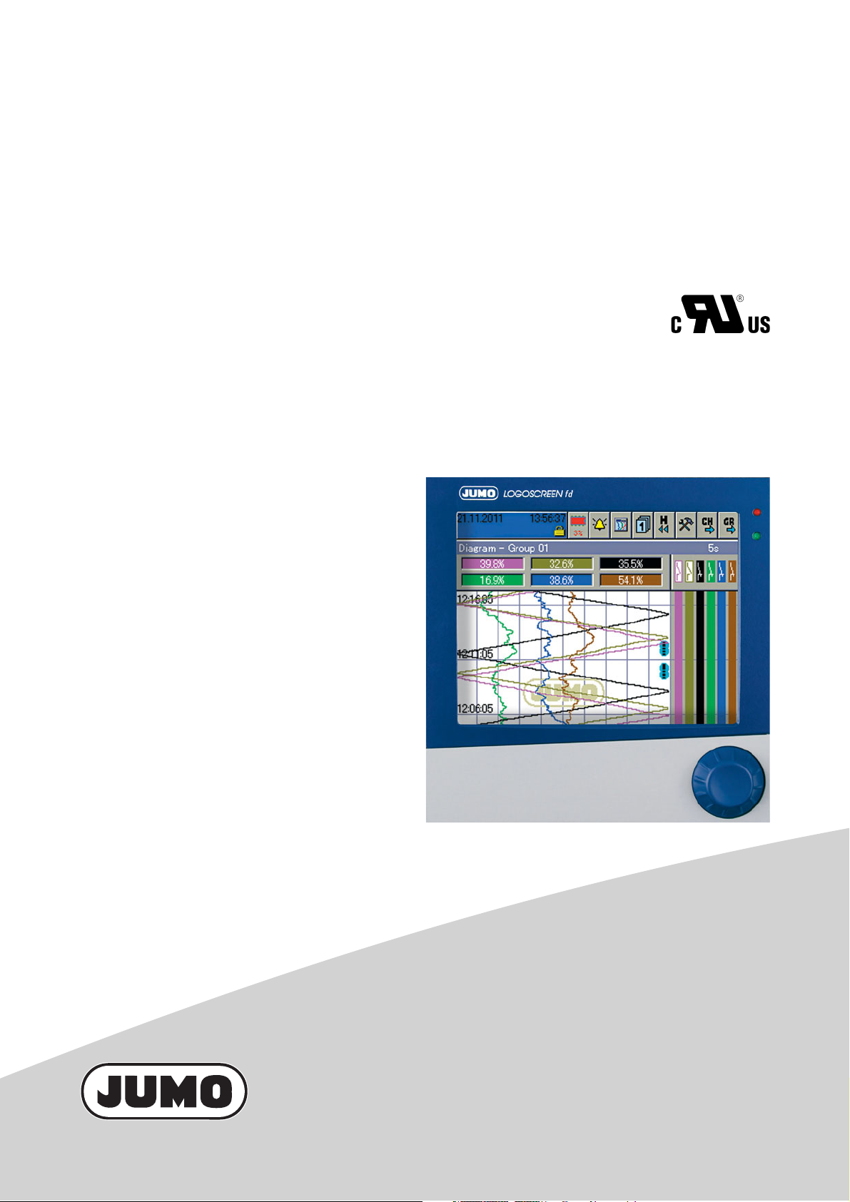
JUMO LOGOSCREEN fd
Secure Data Management and
FDA-Compliant Measured Data Recording
B 706585.4
Installation Instructions
2013-10-23/00586157
Page 2

Page 3

Contents
1 Introduction 5
1.1 Preface .......................................................................................................... 5
1.2 Arrangement of the documentation ........................................................... 6
1.3 Typographical conventions ......................................................................... 9
2 Identifying the instrument version 11
2.1 Nameplate ................................................................................................... 11
2.2 Order details ............................................................................................... 12
2.3 Standard accessories ................................................................................ 13
2.4 Accessories ................................................................................................ 13
3 Installation 15
3.1 Installation site and climatic conditions .................................................. 15
3.2 Dimensions ................................................................................................. 15
3.3 Mounting in a panel .................................................................................... 16
4 Electrical connection 17
4.1 Installation notes ........................................................................................ 17
4.2 Procedure .................................................................................................... 18
4.3 Overview of the electrical isolation .......................................................... 19
4.4 Connection diagram .................................................................................. 20
4.5 Connection examples concerning binary inputs/outputs ...................... 26
5 Functional test 29
6 Technical data (extract from data sheet) 31
6.1 Analog inputs .............................................................................................. 31
Page 4

Contents
6.2 Binary inputs/outputs (option) .................................................................. 34
6.3 Outputs ........................................................................................................ 34
6.4 Interfaces .................................................................................................... 34
6.5 Screen ......................................................................................................... 35
6.6 Electrical data ............................................................................................. 35
6.7 Environmental influences .......................................................................... 36
6.8 Housing ....................................................................................................... 36
6.9 Approvals/marks of conformity ................................................................ 36
7 Glossary 37
Page 5

1.1 Preface
E
B
1 Introduction
Please read these Operating Instructions before commissioning the
instrument. Keep the manual in a place that is accessible to all users at all
times.
Please assist us to improve this operating manual, where necessary.
Your comments will be appreciated.
If any difficulties should arise during commissioning, you are asked
not to carry out any manipulations that could endanger your rights
under the instrument warranty!
Please contact the nearest subsidiary or the head office in such a
case.
When returning modules, assemblies or components, the
regulations of EN 61340-5-1 and EN 61340-5-2 “Protection of
electronic devices from electrostatic phenomena” must be
observed. Use only the appropriate ESD packaging for transport.
Please note that we cannot accept any liability for damage caused
by ESD.
ESD=electrostatic discharge
5
Page 6

1 Introduction
1.2 Arrangement of the documentation
The documentation for this instrument is addressed to equipment
manufacturers (OEMs) and users with appropriate technical expertise. It
consists of the following parts:
Instrument documentation in printed form
B 706585.1 Operating Instructions
The operating instructions are an extract from the operating manual and cover
the basic operation of the paperless recorder.
B 706585.4(.1) Installation Instructions
The installation instructions describe the installation of the recorder and the
connection of the supply and signal cables. The instructions also contain a list
of the technical data.
B 706585.4 Installation instructions for recorders with die-cast zinc front
B 706585.4.1 Installation instructions for recorders with stainless steel front
Instrument documentation in the form of PDF files
The “Instrument documentation in the form of PDF files” is on the CD that is
included in the delivery.
B 706585.0 Operating Manual
It contains information about commissioning, operation, parameterization and
configuration on the instrument.
B 706585.1 Operating Instructions
The operating instructions are an extract from the operating manual and cover
the basic operation of the paperless recorder.
B 706585.2.0 Interface Description (serial interfaces)
This provides information on the communication (RS232/RS485) with
supervisory systems.
Interface Description (Ethernet interface)
This provides information on the connection of a paperless recorder to a
company-internal network. This description is integrated into B 706585.2.0.
B 706585.2.3 Interface Description (PROFIBUS-DP interface)
This provides information on the connection of a paperless recorder to a
PROFIBUS-DP system.
6
Page 7

B 706585.4(.1) Installation Instructions
The installation instructions describe the installation of the recorder and the
connection of the supply and signal cables. The instructions also contain a list
of the technical data.
B 706585.4 Installation instructions for recorders with die-cast zinc front
B 706585.4.1 Installation instructions for recorders with stainless steel front
B 706585.6 Setup Program
The manual describes the function of the setup program. The setup program is
available as an option.
T 706585 Data Sheet
The data sheet contains general information, the order details and the
technical data.
B 709701.0 PC Evaluation software PCA3000
The operating manual describes the operation and the features of the PC
evaluation software.
1 Introduction
PCA3000 serves to visualize and evaluate process data (measurement data,
batch data, messages, instrument audit trails, ...). The process data can be
read in via the CompactFlash memory card, or made available through the
PCC software.
B 709702.0 PCA Communications software PCC
The operating manual describes the operation and the features of the PCA
Communications software.
PCC is responsible for the data transfer from the recorder to a PC, or to a
network.
B 709703.0 PC Security Manager Software PCS
The operating manual describes the operation and the features of the PC
Security Manager software.
The PCS ensures that only authorized persons can gain access to the system
components (instrument, PC software) and use electronic signatures on
electronic documents.
The configuration of the Security Manager can only be performed by the
system administrator.
7
Page 8

1 Introduction
B 709704.0 PC Audit Trail Manager Software PCAT
The operating manual describes the operation and the features of the PC audit
trail manager software.
PCAT documents actions performed in the PC software components, which
lead to modifications of files, user lists (rights files), device lists etc. The
different message types are: “Information”, “Warnings” and “Errors”.
Audit trail records cannot be modified.
Device audit trail data are not shown in PCAT, only in PCA3000.
Internet
All documents are available for downloading at www.jumo.net
8
Page 9

1.3 Typographical conventions
V
E
Warning signs
The signs for Danger and Caution are used in this manual under the following
conditions:
Danger
This symbol is used when there may be danger to personnel if the
instructions are ignored or not followed correctly!
Caution
This symbol is used when there may be damage to equipment or data if the
instructions are ignored or not followed correctly!
Caution
This symbol is used where special care is required when handling
components liable to damage through electrostatic discharge.
1 Introduction
Note signs
h
Note
This symbol is used when your special attention is drawn to a remark.
Reference
This symbol refers to further information in other manuals, chapters or
sections.
Action instruction
This symbol indicates that an action to be performed is described.
The individual steps are marked by this asterisk, e.g.
h Rotate control knob
h Press control knob
9
Page 10

1 Introduction
10
Page 11

2 Identifying the instrument version
2.1 Nameplate
Position The nameplate is glued onto the paperless recorder.
Contents It contains important information, such as:
Description Designation on
the nameplate
Device type Typ 706585/18-321-33/020
Part no. TN 00xxxxxx
Serial no. F-Nr 0022969000013050006
Supply voltage AC 110 — 240 V
Typ Please check the type supplied against your order document. Refer to
Chapter 2.2 “Order details” for identification of the type.
TN The part no. provides an unambiguous definition of an article from the catalog.
It is used in communication between the sales department and the customer.
F-Nr The serial number (F-Nr) indicates the production date (year/week). The figures
concerned are in positions 12, 13, 14, 15.
Example:
F-Nr 0022969000013050006
This shows that the paperless recorder was manufactured in 2013, week 5.
Example
+10/-15%, 48—63Hz
11
Page 12

2 Identifying the instrument version
2.2 Order details
(1) Basic type
706585 LOGOSCREEN fd
(2) Basic type extension
0 No software package
1 With software package (setup program, PCA3000, PCC, PCS, PCAT, USB cable)
(3) Language / Setup
8 Factory setting (German/English)
9 Set to customer specification
(4) Module slot 1
0Not used
2 3 analog inputs and 8 binary inputs/outputs
3 6 analog inputs
(5) Module slot 2
0Not used
2 3 analog inputs and 8 binary inputs/outputs
3 6 analog inputs
(6) Module slot 3
0Not used
1 6 relay outputs
2 3 analog inputs and 8 binary inputs/outputs
3 6 analog inputs
(7) Voltage supply
25 AC/DC 20 to 30 V, 48 to 63 Hz
33 AC 100 to 240 V +10/-15 %, 48 to 63 Hz
(8) Extra codes memory
020 Lithium battery for memory buffering (ex-factory)
021 Storage capacitor
(9) Extra codes
.Not used
260 Math and logic module
(10) Extra codes housing
.Not used
350 Universal carrying case TG-35
444 Stainless steel front with touchpad
(11) Extra codes
. Without extra codes
267 PROFIBUS-DP interface
a
This extra code is available in combination with voltage supply AC 100 to 240 V, not with low supply voltage.
UL and ATEX approvals not applicable. The protection type in the carrying case corresponds to IP20, outside IP20D.
a
Order code (1) (2) (3) (4) (5) (6) (7) (8) (9) (10) (11)
Order example 706585 / - - / , , ,
List extra codes in sequence, separated by commas.
12
Page 13

2 Identifying the instrument version
2.3 Standard accessories
• 1 Installation Instructions B 706585.4
• 1 Operating Instructions B 706585.1
• 4 mounting brackets
•1 panel seal
• 1 CD with detailed operating instructions and supplementary
documentation (see Chapter 1.2 “Arrangement of the documentation”)
2.4 Accessories
• Software package (setup program, PCA3000, PCC, PCS, PCAT)
• CompactFlash memory cards
• USB memory sticks
• USB cable
13
Page 14

2 Identifying the instrument version
14
Page 15

3.1 Installation site and climatic conditions
193
10
21
144
144
The installation site should be as free as possible from vibration.
Electromagnetic fields, such as those caused by motors, transformers,
frequency converter etc. should be avoided as far as possible.
The ambient temperature at the site can be 0 to 50 °C, at a relative humidity of
75 %, no condensation.
v Chapter 4.1 “Installation notes”
3.2 Dimensions
Recorder with
zinc diecast
front
3 Installation
Panel cut-out
15
Page 16

3 Installation
Panel seal
3.3 Mounting in a panel
h Fit panel seal (IP65 seal).
h Insert the paperless recorder from the front into the panel cut-out.
h From behind the panel, hook the four mounting brackets into the grooves
on the sides of the housing and tighten them evenly up against the back of
the panel.
16
Page 17

4.1 Installation notes
• The device is designed for installation in electrical cabinets, machines, or
systems. External fuse protection and shut-off must be provided for the
device. The fuse must not exceed 20 A.
An instrument fuse is already built into the device itself (depending on the
device design).
AC/DC20—30V, 48—63Hz: fuse 2.5A slow-blow
AC 100 — 240 V +10/-15 %, 48 — 63 Hz: fuse 1.25 A slow-blow
• The choice of cable, the installation and the electrical connection must
conform to the requirements of VDE 0100 “Regulations on the Installation
of Power Circuits with Nominal Voltages below 1000 V” or the appropriate
local regulations.
• Work inside the instrument must only be carried out to the extent
described and, like the electrical connection, only by qualified personnel.
• For service and repair work the device must be disconnected from the
power supply (all poles).
• To generate the operating voltage of 20 ... 30 V for Extra Low Voltage
(ELV), the maximum nominal voltage of an external power supply must
not exceed 240 V (line-to-line and line-to-neutral). If the external nominal
voltage is greater than 240 V, an Safety Extra Low Voltage (SELV) power
supply must be used. For line-to-line supply of the external power supply,
the power supply must have all-pole fuse protection. The fuse must shut
off both connections.
4 Electrical connection
• Run input, output and supply cables separately and not parallel to one
another.
• In EMC disturbed environments, all input and output cables without
connection to the mains supply must be arranged as twisted and
screened cables. Earth the screen on the instrument side to the earth
potential.
• Ground the instrument at the PE terminal of the supply voltage connector
to the protective earth conductor. This cable must have the same crosssection as that used for the supply cables. Earthing cables must be wired
in a star configuration to a common earth point that is connected to the
protective earth conductor of the electrical supply.
• Do not connect any additional loads to the supply terminals of the
instrument.
• The device is not suitable for use in areas with an explosion hazard (Ex
areas).
• Electromagnetic compatibility (EMC) conforms to the standards and
regulations cited in the technical data.
v Chapter 6 “Technical data (extract from data sheet)”
• Inductive loads close to the instrument, such as contactors or solenoid
valves, should have RC modules fitted for interference suppression.
17
Page 18

4 Electrical connection
Module slot 3 (top)
Relay card
}
Module slot 2 (middle)
6 analog channels or
3 analog channels and
8 binary inputs/outputs
}
Module slot 1 (bottom)
6 analog channels or
3 analog channels and
8 binary inputs/outputs
}
21
22
23
31
32
33
41
42
43
51
52
53
61
62
63
71
72
73
123
4
10 11
12
1
2
3
4
5
6
9
8
7
B12
B 9
B10
B11
B13
B14
B15
B16
B4
B1
B2
B3
B5
B6
B7
B8
+
+
+
U
U
+
-
-
--
in
out
U
U
out
U
U
in
33
44
11
22
12341234123
4
12341234123
4
12341234123
4
8.
9.
11.
10.
14.
3.
2.
1.
12
13
11
5.
6.
7.
PE
N
L1
(L+)
(L-)
4.
15.
Connector number
13
14
15
16
17
18
4
3
2
1
B20
B17
B18
B19
B21
B22
B23
B24
B12
B 9
B10
B11
B13
B14
B15
B16
B4
B1
B2
B3
B5
B6
B7
B8
+
+
U
U
U
+
+
U
U
+
+
U
-
-
-
-
-
-
in
out
in
out
in
out
123
4
123
4
123
4
9
8
7
123
4
10 11
123
4
123
4
12
1
2
3
4
1
2
3
4
1
2
1
2
3
4
3
1
2
3
4
1
2
3
4
1
5
4
2
3
4
6
11
22
33
44
1
2
3
4
11
22
33
44
12.
13.
11.
9.
8.
10.
3.
2.
1.
12
13
11
5.
6.
7.
PE
N
L1
(L+)
(L-)
4.
15.
}
Module slot 2 (middle)
6 analog channels or
3 analog channels and
8 binary inputs/outputs
}
Module slot 1 (bottom)
6 analog channels or
3 analog channels and
8 binary inputs/outputs
}
Connector number
Module slot 3 (top)
6 analog channels or
3 analog channels and
8 binary inputs/outputs
4.2 Procedure
h Make the electrical connection as per Chapter 4.4 “Connection diagram”.
h Apply strain relief for the connecting cables, if necessary.
Instrument
variant 1
Instrument
variant 2
18
Page 19

Connector
Binary
inputs/outputs
Ethernet
interface
Relay
contacts
Test voltage
contacts to
relay coil
2.3kV AC
Test voltage
AC supply: 2.3kV/50Hz
AC/DC supply: 2.3kV/50Hz
RS232 for
barcode reader
Supply
AC or AC/DC
Serial interface
RS232 / RS485
CompactFlash
memory card
USB
interfaces
Analog input 1 — 18
summary
4 Electrical connection
Connector/slot Function
1 Relay output
2 RS232 for barcode reader
3 PROFIBUS-DP
4 Supply voltage
5 USB host interface
6Ethernet
7 RS232 and RS485
8 Analog input
9 Analog input or binary inputs/outputs
10 Analog input
11 Analog input or binary inputs/outputs
12 Analog input
13 Analog input or binary inputs/outputs
14 Relay card (for instrument variant 1)
15 USB device interface
4.3 Overview of the electrical isolation
19
Page 20

4 Electrical connection
V
3.
2.
1.
12
13
11
PE
N
L1
(L+)
(L-)
4.
PE
N
L1
(L+)
(L-)
4.
L1 N
L1 N
PE
PE
21
22
23
31
32
33
414243
51
52
53
61
62
63
71
72
73
123
4
10 11
12
1
2
3
4
5
6
9
8
7
B12
B9
B10
B11
B13
B14
B15
B16
B4
B1
B2
B3
B5
B6
B7
B8
+
+
+
U
U
+
-
-
--
in
out
U
U
out
U
U
in
33
44
11
22
12341234123412341234123
4
12341234123
4
8.
9.
11.
10.
14.
3.
2.
1.
12
13
11
5.
6.
7.
PE
N
L1
(L+)
(L-)
4.
15.
123
4
10 11
12
1
2
3
4
5
6
9
8
7
B12
B9
B10
B11
B13
B14
B15
B16
B4
B1
B2
B3
B5
B6
B7
B8
+
+
+
U
U
+
-
-
--
in
out
U
U
out
U
U
in
33
44
11
22
12341234123412341234123
4
12341234123
4
8.
9.
11.
10.
13
14
15
16
17
18
4
3
2
1
B20
B17
B18
B19
B21
B22
B23
B24
B12
B9
B10
B11
B13
B14
B15
B16
B4
B1
B2
B3
B5
B6
B7
B8
+
+
U
U
U
+
+
U
U
+
+
U
-
-
-
-
-
-
in
out
in
out
in
out
1
2
3
4
1
2
3
4
1
2
3
4
9
8
7
1
2
3
4
10 11
1
2
3
4
1
2
3
4
12
1
2
3
4
1
2
3
4
1
2
1
2
3
4
3
1
2
3
4
1
2
3
4
1
5
4
2
3
4
6
11
22
33
44
1
2
3
4
11
22
33
44
12.
13.
11.
9.
8.
10.
3.
2.
1.
12
13
11
5.
6.
7.
PE
N
L1
(L+)
(L-)
4.
15.
13
14
15
16
17
18
4
3
2
1
B20
B17
B18
B19
B21
B22
B23
B24
B12
B9
B10
B11
B13
B14
B15
B16
B4
B1
B2
B3
B5
B6
B7
B8
+
+
U
U
U
+
+
U
U
+
+
U
-
-
-
-
-
-
in
out
in
out
in
out
1
2
3
4
1
2
3
4
1
2
3
4
9
8
7
1
2
3
4
10 11
1
2
3
4
1
2
3
4
12
1
2
3
4
1
2
3
4
1
2
1
2
3
4
3
1
2
3
4
1
2
3
4
1
5
4
2
3
4
6
11
22
33
44
1
2
3
4
11
22
33
44
12.
13.
11.
9.
8.
10.
2134
+
–
2134
2134
2134
2134
ESA
2134
2134
2134
4.4 Connection diagram
The electrical connection must only
be carried out by specialist personnel.
Back panel v Chapter 4.2 “Procedure”
Connections
Terminal assignment Connector Diagram
Supply
voltage
Supply voltage
as on nameplate
Analog inputs Thermocouple
RTD temperature probe
2-wire circuit
RTD temperature probe
3-wire circuit
RTD temperature probe
4-wire circuit
Connector 4
L1 (L+)
N (L-)
PE
Connectors
8 to 11
(input 1—12)
for instrument
variant 1
20
Resistance transmitter
E = end
S = slider
A = start
Potentiometer in
2-wire circuit
or
connectors
8 to 13
(input 1—18)
for instrument
variant 2
Potentiometer in
3-wire circuit
Potentiometer in
4-wire circuit
Page 21

4 Electrical connection
21
22
23
31
32
33
414243
51
52
53
61
62
63
71
72
73
123
4
10 11
12
1
2
3
4
5
6
9
8
7
B12
B9
B10
B11
B13
B14
B15
B16
B4
B1
B2
B3
B5
B6
B7
B8
+
+
+
U
U
+
-
-
--
in
out
U
U
out
U
U
in
33
44
11
22
12341234123412341234123
4
12341234123
4
8.
9.
11.
10.
14.
3.
2.
1.
12
13
11
5.
6.
7.
PE
N
L1
(L+)
(L-)
4.
15.
123
4
10 11
12
1
2
3
4
5
6
9
8
7
B12
B9
B10
B11
B13
B14
B15
B16
B4
B1
B2
B3
B5
B6
B7
B8
+
+
+
U
U
+
-
-
--
in
out
U
U
out
U
U
in
33
44
11
22
12341234123412341234123
4
12341234123
4
8.
9.
11.
10.
13
14
15
16
17
18
4
3
2
1
B20
B17
B18
B19
B21
B22
B23
B24
B12
B9
B10
B11
B13
B14
B15
B16
B4
B1
B2
B3
B5
B6
B7
B8
+
+
U
U
U
+
+
U
U
+
+
U
-
-
-
-
-
-
in
out
in
out
in
out
1
2
3
4
1
2
3
4
1
2
3
4
9
8
7
1
2
3
4
10 11
1
2
3
4
1
2
3
4
12
1
2
3
4
1
2
3
4
1
2
1
2
3
4
3
1
2
3
4
1
2
3
4
1
5
4
2
3
4
6
11
22
33
44
1
2
3
4
11
22
33
44
12.
13.
11.
9.
8.
10.
3.
2.
1.
12
13
11
5.
6.
7.
PE
N
L1
(L+)
(L-)
4.
15.
13
14
15
16
17
18
4
3
2
1
B20
B17
B18
B19
B21
B22
B23
B24
B12
B9
B10
B11
B13
B14
B15
B16
B4
B1
B2
B3
B5
B6
B7
B8
+
+
U
U
U
+
+
U
U
+
+
U
-
-
-
-
-
-
in
out
in
out
in
out
1
2
3
4
1
2
3
4
1
2
3
4
9
8
7
1
2
3
4
10 11
1
2
3
4
1
2
3
4
12
1
2
3
4
1
2
3
4
1
2
1
2
3
4
3
1
2
3
4
1
2
3
4
1
5
4
2
3
4
6
11
22
33
44
1
2
3
4
11
22
33
44
12.
13.
11.
9.
8.
10.
Terminal assignment Connector Diagram
Analog inputs Voltage input 0 — 1 V Connectors
8 to 11
(input 1—12)
Voltage input 0 — 10 V
Current input
for instrument
variant 1
or
connectors
8 to 13
(input 1—18)
for instrument
variant 2
21
Page 22

4 Electrical connection
13
14
15
16
17
18
4
3
2
1
B20
B17
B18
B19
B21
B22
B23
B24
B12
B9
B10
B11
B13
B14
B15
B16
B4
B1
B2
B3
B5
B6
B7
B8
+
+
U
U
U
+
+
U
U
+
+
U
-
-
-
-
-
-
in
out
in
out
in
out
1
2
3
4
1
2
3
4
1
2
3
4
9
8
7
1
2
3
4
10 11
1
2
3
4
1
2
3
4
12
1
2
3
4
1
2
3
4
1
2
1
2
3
4
3
1
2
3
4
1
2
3
4
1
5
4
2
3
4
6
11
22
33
44
1
2
3
4
11
22
33
44
12.
13.
11.
9.
8.
10.
3.
2.
1.
12
13
11
5.
6.
7.
PE
N
L1
(L+)
(L-)
4.
15.
B4
B1
B2
B3
B5
B6
B7
B8
+
+
U
U
-
-
in
out
1
2
3
4
1
2
3
4
1
5
4
2
3
4
6
9.
B2
B3
B4
B5
B6
B7
B8
+
-+
B1
-
UinU
out
+-
24V external
supply voltage
Load
B1
B2
B3
B4
B5
B6
B7
B8
Uin+
Uin-
Uout+
Uout-
13
14
15
16
17
18
4
3
2
1
B20
B17
B18
B19
B21
B22
B23
B24
B12
B9
B10
B11
B13
B14
B15
B16
B4
B1
B2
B3
B5
B6
B7
B8
+
+
U
U
U
+
+
U
U
+
+
U
-
-
-
-
-
-
in
out
in
out
in
out
1
2
3
4
1
2
3
4
1
2
3
4
9
8
7
1
2
3
4
10 11
1
2
3
4
1
2
3
4
12
1
2
3
4
1
2
3
4
1
2
1
2
3
4
3
1
2
3
4
1
2
3
4
1
5
4
2
3
4
6
11
22
33
44
1
2
3
4
11
22
33
44
12.
13.
11.
9.
8.
10.
3.
2.
1.
12
13
11
5.
6.
7.
PE
N
L1
(L+)
(L-)
4.
15.
B12
B9
B10
B11
B13
B14
B15
B16
U
+
+
U
-
-
in
out
1
2
3
4
10 11
1
2
3
4
1
2
3
4
12
11.
B10
B11
B12
B13
B14
B15
B16
+
-+
B9
-
UinU
out
B9
B10
B11
B12
B13
B14
B15
B16
Uin+
Uin-
Uout+
Uout-
Terminal assignment Connector Diagram
Binary inputs/
outputs
H The configuration in the instrument or in the setup program
defines whether it is a binary input or binary output.
B1 ... B8
voltage-controlled
LOW = -3 to +5 V DC
HIGH = 12 to 30 V DC
B1 Binary input/output 1
B2 Binary input/output 2
B3 Binary input/output 3
B4 Binary input/output 4
B5 Binary input/output 5
B6 Binary input/output 6
B7 Binary input/output 7
B8 Binary input/output 8
U
+external supply
in
voltage
U
- ground
in
++24V (60mA) internal
U
out
supply voltage
U
- ground
out
Connector 9
only for modules
with 3 analog
inputs
Example:
Connecting a load to
binary output 4 (B4)
and a solid-state
relay to binary
output 3 (B3) requires
an external supply
voltage.
Diagram of the
connector:
B9 ... B16
Connector 11
only for modules
voltage-controlled
LOW = -3 to +5 V DC
HIGH = 12 to 30 V DC
B9 Binary input/output 9
B10 Binary input/output 10
with 3 analog
inputs
Example:
Binary input 12 (B12)
is operated from the
internal supply
voltage.
B11 Binary input/output 11
B12 Binary input/output 12
B13 Binary input/output 13
B14 Binary input/output 14
Diagram of the
connector:
B15 Binary input/output 15
B16 Binary input/output 16
+external supply
U
in
voltage
- ground
U
in
U
++24V (60mA) internal
out
supply voltage
- ground
U
out
22
Page 23

4 Electrical connection
13
14
15
16
17
18
4
3
2
1
B20
B17
B18
B19
B21
B22
B23
B24
B12
B9
B10
B11
B13
B14
B15
B16
B4
B1
B2
B3
B5
B6
B7
B8
+
+
U
U
U
+
+
U
U
+
+
U
-
-
-
-
-
-
in
out
in
out
in
out
1
2
3
4
1
2
3
4
1
2
3
4
9
8
7
1
2
3
4
10 11
1
2
3
4
1
2
3
4
12
1
2
3
4
1
2
3
4
1
2
1
2
3
4
3
1
2
3
4
1
2
3
4
1
5
4
2
3
4
6
11
22
33
44
1
2
3
4
11
22
33
44
12.
13.
11.
9.
8.
10.
3.
2.
1.
12
13
11
5.
6.
7.
PE
N
L1
(L+)
(L-)
4.
15.
16
17
18
B20
B17
B18
B19
B21
B22
B23
B24
U
+
+
U
-
-
in
out
1
2
3
4
11
22
33
44
13.
B18
B19
B20
B21
B22
B23
B24
+
-+
B17
-
UinU
out
B17
B18
B19
B20
B21
B22
B23
B24
Uin+
Uin-
Uout+
Uout-
3.
2.
1.
12
13
11
PE
N
L1
(L+)
(L-)
4.
1.
12
13
11
1312
11
21
22
23
31
32
33
41
42
43
51
52
53
61
62
63
71
72
73
123
4
10 11
12
1
2
3
4
5
6
9
8
7
B12
B9
B10
B11
B13
B14
B15
B16
B4
B1
B2
B3
B5
B6
B7
B8
+
+
+
U
U
+
-
-
--
in
out
U
U
out
U
U
in
33
44
11
22
1
2
3
4
1
2
3
4
1
2
3
4
1
2
3
4
1
2
3
4
1
2
3
4
12341234123
4
8.
9.
11.
10.
14.
3.
2.
1.
12
13
11
5.
6.
7.
PE
N
L1
(L+)
(L-)
4.
15.
21
22
23
31
32
33
41
42
43
51
52
53
61
62
63
71
72
73
14.
2322
21
3332
31
4342
41
5352
51
6362
61
7372
71
Terminal assignment Connector Diagram
Binary inputs/
B17 ... B24
outputs
voltage-controlled
LOW = -3 to +5 V DC
HIGH = 12 to 30 V DC
B17 Binary input/output 17
B18 Binary input/output 18
B19 Binary input/output 19
B20 Binary input/output 20
B21 Binary input/output 21
B22 Binary input/output 22
B23 Binary input/output 23
B24 Binary input/output 24
U
+external supply
in
voltage
U
- ground
in
++24V (60mA) internal
U
out
supply voltage
U
- ground
out
Relay outputs Relay 1 - alarm
changeover (SPDT)
Connector 13
only for
instrument
variant 2
and on modules
with 3 analog
inputs
Connector 1
Example:
Binary input 20 (B20)
is operated from the
internal supply
voltage.
Diagram of the
connector:
Relay 2
changeover (SPDT)
Relay 3
changeover (SPDT)
Relay 4
changeover (SPDT)
Relay 5
changeover (SPDT)
Relay 6
changeover (SPDT)
Relay 7
changeover (SPDT)
Connector 14
only for
instrument
variant 1
23
Page 24

4 Electrical connection
3.
2.
1.
12
13
11
PE
N
L1
(L+)
(L-)
4.
2.
2
1
3
4
5
6
7
8
9
3.
2.
1.
12
13
11
PE
N
L1
(L+)
(L-)
4.
3.
2
1
3
4
5
6
7
8
9
5.
6.
7.
15.
5.
5.
6.
7.
15.
6.
8
1
5.
6.
7.
15.
7.
2
1
3
4
5
6
7
8
9
Terminal assignment Connector Diagram
Interfaces RS232C for barcode reader
9-pin SUB-D socket connector
2 RxD receive data
3 TxD transmit data
5 GND ground
PROFIBUS-DP
9-pin SUB-D socket connector
(extra code)
3 RxD/TxD-P B conductor
Receive/transmit data
positive
5 DGND
Data transmission ground
6 VP supply voltage positive
8 RxD/TxD-N A conductor
Receive/transmit data
negative
USB host interface
for memory sticks
The recorder without stainless
steel front also has a USB host
interface on the front panel,
connected in parallel. The two
interfaces cannot both be
operated at the same time.
Connector 2
Connector 3
Connector 5
Ethernet
RJ45 socket connector
1 TX+ transmit data +
2 TX- transmit data 3RX+ receive data +
6RX+ receive data -
RS232C
9-pin SUB-D socket connector
(switchable to RS485)
2 RxD receive data
3 TxD transmit data
5 GND ground
Connector 6
Connector 7
24
Page 25

4 Electrical connection
5.
6.
7.
15.
7.
2
1
3
4
5
6
7
8
9
5.
6.
7.
15.
15.
Terminal assignment Connector Diagram
RS485
9-pin SUB-D socket connector
(switchable to RS232)
3TxD+/RxD+
Transmit/receive data +
5 GND ground
8TxD-/RxD-
Transmit/receive data -
USB device interface
for connecting a PC
The recorder without stainless
steel front also has a USB
device interface on the front
panel, connected in parallel.
The two interfaces cannot both
be operated at the same time.
Connector 7
Connector 15
25
Page 26

4 Electrical connection
paperless
recorder
paperless
recorder
4.5 Connection examples concerning binary inputs/outputs
Binary inputs Triggering via external relays and external supply voltage:
Triggering via external relays and internal supply voltage:
26
Page 27

4 Electrical connection
paperless
recorder
paperless
recorder
Triggering via external opto-coupler and internal supply voltage:
Triggering via external switches (potential-free) and internal supply voltage:
27
Page 28

4 Electrical connection
paperless
recorder
paperless
recorder
Binary outputs Triggering of external relays via external supply voltage:
Triggering of external relays via internal supply voltage:
By triggering the external relays via the internal supply voltage the total
current must not exceed 60 mA.
28
Page 29

Start-up screen
5 Functional test
After the paperless recorder has been installed and wired up, it can be
commissioned. After applying or switching on the supply voltage, the start-up
screen will appear for a short time.
The visualization will start automatically after the initialization phase.
Visualization
Further steps
The paperless recorder is now in the recording phase.
The recorder can be configured by an authorized person, either by
using the control knob (rotating and pressing) or with the help of
the PC setup program.
Further information about configuration can be found in the
Operating Manual B 706585.0.
Finally, make another check that the connection, configuration and
function of the recorder are all correct.
29
Page 30

5 Functional test
30
Page 31

6 Technical data (extract from data sheet)
6.1 Analog inputs
Thermocouple
Designation Measuring range Accuracy
Fe-CuNi L DIN 43710
Fe-CuNi J EN 60584
Cu-CuNi U DIN 43710
Cu-CuNi T EN 60584
NiCr-Ni K EN 60584
NiCr-CuNi E EN 60584
NiCrSi-NiSi N EN 60584
Pt10Rh-Pt S EN 60584
Pt13Rh-Pt R EN 60584
Pt30Rh-Pt6Rh B EN 60584
W3Re/W25Re D
W5Re/W26Re C
W3Re/W26Re
Chromel-copel GOST R 8.585-2001
Chromel-alumel GOST R 8.585-2001
PLII (Platinel II)
Shortest span Type L, J, U, T, K, E, N, chromel-alumel, PLII: 100 °C
Range start/end freely programmable within the limits, in 0.1 °C steps
Cold junction Pt100 internal or thermostat external constant
Cold junction accuracy (internal) ±1 °C
Cold junction temperature (external) -50 to +150 °C adjustable
Sampling cycle Channel 1 to 18: 125 ms in total
Input filter 2nd order digital filter; filter constant adjustable from 0 to 10.0 sec
Electrical isolation see “Electrical data” on page 35 and
Resolution > 14 bit
Features also programmable in °F
a
The linearization accuracy refers to the maximum measuring range. The linearization accuracy is reduced
with short spans.
-200 to +900 °C
-200 to +1200 °C
-200 to +600 °C
-270 to +400 °C
-200 to +1372 °C
-200 to +1000 °C
-100 to +1300 °C
0 to 1768 °C
0 to 1768 °C
0 to 1820 °C
0 to 2495 °C
0 to 2320 °C
0 to 2400 °C
-200 to +800 °C
-200 to +1372 °C
0 to 1395 °C
Type S, R, B, D, C, W3Re/W26Re, chromel-copel: 500 °C
“Overview of the electrical isolation” on page 19
±0.1 %
±0.1 % from -100 °C
±0.1 % from -150 °C
±0.1 % from -150 °C
±0.1 % from -80 °C
±0.1 % from -80 °C
±0.1 % from -80 °C
±0.15 %
±0.15 %
±0.15 % from 400 °C
±0.15 % from 500 °C
±0.15 % from 500 °C
±0.15 % from 500 °C
±0.15 % from -80 °C
±0.1 % from -80 °C
±0.15 %
a
RTD temperature probe
Designation Connection
circuit
Pt100 EN 60751
(TC = 3.85*10
Pt100 JIS 1604
(TC = 3.917*10
Pt100 GOST 6651-94 A.1
(TC = 3.91*10
Pt500 EN 60751
(TC = 3.85*10
Pt1000 EN 60751
(TC = 3.85*10
-3
1/°C)
-3
-3
1/°C)
-3
1/°C)
-3
1/°C)
1/°C)
2-/3-wire
2-/3-wire
4-wire
2-/3-wire
2-/3-wire
4-wire
2-/3-wire, 4-wire
2-/3-wire, 4-wire
2-/3-wire, 4-wire
2-/3-wire, 4-wire
2-/3-wire
2-/3-wire
4-wire
Measuring range AccuracyaMeasurement
current
-200 to +100 °C
-200 to +850 °C
-200 to +850 °C
-200 to +100 °C
-200 to +650 °C
-200 to +650 °C
-200 to +100 °C
-200 to +850 °C
-200 to +100 °C
-200 to +850 °C
-200 to +100 °C
-200 to +850 °C
-200 to +850 °C
±0.5 °C
±0.8 °C
±0.5 °C
±0.5 °C
±0.8 °C
±0.5 °C
±0.5 °C
±0.8 °C
±0.5 °C
±0.9 °C
±0.5 °C
±0.8 °C
±0.5 °C
250 µA
250 µA
250 µA
250 µA
250 µA
250 µA
250 µA
250 µA
100 µA
100 µA
100 µA
100 µA
100 µA
31
Page 32

6 Technical data (extract from data sheet)
Designation Connection
circuit
Ni100 DIN 43760
(TC = 6.18*10
Pt50 ST RGW 1057 1985
(TC = 3.91*10
Cu50
(TC = 4.26*10
Cu100 GOST 6651-94 A.4
(TC = 4.26*10
Connection circuit 2-, 3-, or 4-wire circuit
Shortest span 15 °C
Sensor lead resistance max. 30 per conductor for 3-wire/4-wire circuit
Range start/end freely programmable within the limits, in 0.1 °C steps
Sampling cycle Channel 1 to 18: 125 ms in total
Input filter 2nd order digital filter; filter constant adjustable from 0 to 10 sec
Electrical isolation see “Electrical data” on page 35 and
Resolution > 14 bit
Features also programmable in °F
a
The linearization accuracy refers to the maximum measuring range. The linearization accuracy is reduced
with short spans.
-3
1/°C)
-3
1/°C)
-3
1/°C)
-3
1/°C)
2-/3-wire, 4-wire -60 to +180 °C ±0.4 °C
2-/3-wire
2-/3-wire
4-wire
4-wire
2-/3-wire
2-/3-wire
4-wire
4-wire
2-/3-wire
2-/3-wire
4-wire
4-wire
max. 10 per conductor for 2-wire circuit
“Overview of the electrical isolation” on page 19
Measuring range AccuracyaMeasurement
current
250 µA
-200 to +100 °C
-200 to +1100 °C
-200 to +100 °C
-200 to +1100 °C
-50to+100°C
-50to+200°C
-50to+100°C
-50to+200°C
-50to+100°C
-50to+200°C
-50to+100°C
-50to+200°C
±0.5 °C
±0.9 °C
±0.5 °C
±0.6 °C
±0.5 °C
±0.9 °C
±0.5 °C
±0.7 °C
±0.5 °C
±0.9 °C
±0.5 °C
±0.6 °C
250 µA
250 µA
250 µA
250 µA
250 µA
250 µA
250 µA
250µA
250 µA
250 µA
250 µA
250 µA
Resistance transmitter and potentiometer
Designation Measuring range Accuracy
Resistance transmitter up to 4000 ±4 100 µA
Potentiometer
to 4000
Connection circuit resistance transmitter: 3-wire circuit
potentiometer: 2-/3-/4-wire circuit
Shortest span 60
Sensor lead resistance max. 30 per conductor for 4-wire circuit
max. 10 per conductor for 2-/3-wire circuit
Resistance values freely programmable within the limits, in 0.1 steps
Sampling cycle Channel 1 to 18: 125 ms in total
Input filter 2nd order digital filter; filter constant adjustable from 0 to 10.0 sec
Electrical isolation see “Electrical data” on page 35 and
“Overview of the electrical isolation” on page 19
Resolution > 14 bit
a
The linearization accuracy refers to the maximum measuring range. The linearization accuracy is reduced
with short spans.
±400 m
±4
a
Measurement
current
250 µA
100 µA
32
Page 33

6 Technical data (extract from data sheet)
Input for DC voltage, DC current
Basic range Accuracy
-12 to +112 mV
-10 to +210 mV
-1.5 to +11.5 V
-0.12 to +1.12 V
-1.2 to +1.2 V
-11.2 to +11.2 V
±100 V
±240 V
±6 mV
±1 mV
±2 mV
±12 mV
Shortest span 5 mV
Range start/end freely programmable within the limits in 0.01 mV steps
-1.3 to +22 mA
-22 to +22 mA
±20 A
±44 A
Shortest span 0.5mA
Range start/end freely programmable within the limits in 0.01 mA steps
Overrange/underrange according to NAMUR NE 43
Sampling cycle Channel 1 to 18: 125 ms in total
Input filter 2nd order digital filter; filter constant adjustable from 0 to 10.0 sec
Electrical isolation see “Electrical data” on page 35 and
“Overview of the electrical isolation” on page 19
Resolution >14 bit
a
The linearization accuracy refers to the maximum measuring range. The linearization accuracy is reduced
with short spans.
a
Input resistance
R
1M
E
R
470 k
E
R
470 k
E
R
470 k
E
R
470 k
E
R
470 k
E
burden voltage 3V
burden voltage 3V
Transducer short circuit/break
Short-circuit
a
Thermocouple not detected detected
RTD temperature probe detected detected
Resistance transmitter not detected detected
Potentiometer not detected detected
Voltage ±210 mV not detected detected
Voltage > ±210 mV not detected not detected
Current not detected not detected
a
Programmable reaction of device, e.g. triggering alarm
Break
a
33
Page 34

6 Technical data (extract from data sheet)
6.2 Binary inputs/outputs (option)
Input or output configurable as input or output
Number 8, 16 or 24, depending on the device version,
to DIN VDE 0411, Part 500; max. 25 Hz, max. 32 V
Input
• level logic "0": -3 to +5 V (input current max. ±1 mA),
logic "1": 12 to 30 V (2.5 mA input current 5mA)
• counting frequency 8Hz
High-speed input the first two binary inputs of each module (B1, B2, B9, B10, B17, B18),
if the module is not fitted with relays or 6 analog inputs
• task count function, e.g. for flow measurement
• counting frequency 10 kHz
Output
• type open-collector output, switches relative to positive voltage
• level logic "0": transistor is inhibited
(max. permissible voltage across switching transistor 30 V,
max. leakage current 0.1 mA)
logic "1": transistor is switched on
(max. voltage across switching transistor 1.6 V, max. current 50 mA)
• sampling cycle at least 1 sec (1 Hz)
6.3 Outputs
1 relay (ex-factory) changeover (SPDT), 3 A, 230 V AC
6 relays (option) changeover (SPDT), 3 A, 230 V AC
a
With resistive load.
b
It is not permissible to mix SELV circuits and supply circuits.
a
a, b
6.4 Interfaces
RS232/RS485 (connector 7) Qty. 1, switchable between RS232 and RS485
• protocol Modbus master, Modbus slave and barcode reader
• baud rate 9600, 19200, 38400
• modem can be connected
•connector SUB-D
• external inputs via the Modbus master/slave function, 24 analog and 24 binary
RS232 for barcode reader
(connector 2)
• protocol Modbus master, Modbus slave and barcode reader
• baud rate 9600, 19200, 38400
•connector SUB-D
• external inputs via the Modbus master/slave function, 24 analog and 24 binary
Ethernet (connector 6)
• quantity max. 1
• protocols TCP, IP, HTTP, DHCP, SMTP, ModbusTCP
• baud rate 10 Mbits/sec, 100 Mbits/sec
•connector RJ45
• data format HTML
Qty. 1
34
Page 35

6 Technical data (extract from data sheet)
USB host (connector 5)
• quantity 2 (or 1 with stainless steel front),
connector 5 and front connector (not with stainless steel front); no
parallel operation
• use for connecting a memory stick
• max. current 100 mA
USB device (connector 15)
• quantity 2 (or 1 with stainless steel front), connector 15 and front connector
(not with stainless steel front); no parallel operation)
• use for connecting to the (master) computer
6.5 Screen
Resolution/size 320 × 240 pixels/5.5"
Type/number of colors TFT color screen/256 colors
Screen refresh rate > 150 Hz
Brightness setting adjustable on instrument
Screen saver (switch-off) through waiting time or control signal
6.6 Electrical data
Supply voltage (switch-mode PSU) AC 100 to 240V +10/-15%, 48 - 63Hz or
AC/DC 20 to 30V, 48 - 63Hz (ELV)
Electrical safety to EN 61010, Part 1, August 2002
overvoltage category II, pollution degree 2
Protection class I terminal for PE conductor
Test voltages (type test)
• mains supply circuit to meas.
circuit
• mains supply circuit to housing
(protective conductor)
• measuring current circuits to
measuring current circuit and
housing 500 V/50 Hz, 1 min
• electrical isolation between
analog inputs up to 30 V AC and 50 V DC
Supply voltage error < 0.1 % of range span
Power consumption approx. 40 VA
Data backup CompactFlash memory card
Electrical connection
• mains supply and relays at rear through pluggable screw terminals, 5.08 mm raster,
• analog and binary inputs at rear through pluggable screw terminals, 3.81 mm raster,
with AC supply: 2.3 kV/50 Hz, 1 min,
with AC/DC supply: 2.3 kV/50 Hz, 1 min
with AC supply: 2.3 kV/50 Hz, 1 min,
with AC/DC supply: 2.3 kV/50 Hz, 1 min
max. conductor cross-section 2.5 mm
max. conductor cross-section 1.5 mm
2
or 2× 1.5 mm2 with ferrules
2
35
Page 36

6 Technical data (extract from data sheet)
6.7 Environmental influences
Ambient temperature range 0 to +50 °C
Ambient temperature effect 0.03 %/°C
Storage temperature range -20 to +60 °C
Climatic conditions 75 % relative humidity, no condensation
EMC EN 61326-1
• interference emission Class A - only for industrial use -
• immunity to interference to industrial requirements
6.8 Housing
Housing front zinc die-casting, optionally in stainless steel (extra code)
Housing type housing for flush-panel mounting to IEC 61554, in stainless steel
Bezel size 144 mm × 144 mm to IEC 61554
Depth behind panel 193 mm (incl. terminals)
Panel cut-out 138
Panel thickness 2 to 40 mm
Housing mounting in panel to DIN 43834
Operating position unrestricted, but taking into account the viewing angle of the screen,
Enclosure protection to EN 60529 Category 2, front IP65, rear IP20
Weight approx. 3.5 kg
+1.0
mm × 138
horizontally ±65°, vertically +40° to -65°
+1.0
mm to IEC 61554
6.9 Approvals/marks of conformity
Mark of conformity Testing
laboratory
c UL us Underwriters
Laboratories
II 2G Ex px IIC
II 2D Ex px IIIC IP65
electrosuisse SEV 08 ATEX 0155 U EN 60079-0:2009
Certificates/
certification
numbers
E 201387 UL 61010-1
Test basis valid for
the flush-mounted
CAN/CSAC22.2 No. 61010-1
EN 60079-2:2007
EN 61241-4:2006
instrument; not in
conjunction with extra
code 350
the flush-mounted
instrument; only in
conjunction with
extra code 444 and
without extra code
350
36
Page 37

A
Accessories 13
B
Back panel 20
C
Climatic conditions 15
Commissioning 5
CompactFlash 7
Connection diagram 20
D
Dimensions 15
Documentation, arrangement of 6
7 Glossary
E
Electrical connection 17
Electrostatic discharge (ESD) 5
F
Functional test 29
I
Installation 15
Installation notes 17
Installation site 15
Instrument documentation in printed form 6
Instrument documentation in the form of PDF files 6
Instrument version, identification of 11
Introduction 5
M
Mounting 16
N
Note signs 9
37
Page 38

7 Glossary
O
Order details 12
P
Panel mounting 16
R
Returning 5
S
Standard accessories 13
Start-up screen 29
T
Technical data 31
Typographical conventions 9
V
Views 15
Visualization level 29
W
Warning signs 9
Warranty 5
38
Page 39

Page 40

JUMO GmbH & Co. KG JUMO Instrument Co. Ltd. JUMO Process Control, Inc.
Street address:
Moritz-Juchheim-Straße 1
36039 Fulda, Germany
Delivery address:
Mackenrodtstraße 14
36039 Fulda, Germany
Postal address:
36035 Fulda, Germany
Phone: +49 661 6003-0
Fax: +49 661 6003-607
E-mail: mail@jumo.net
Internet: www.jumo.net
JUMO House
Temple Bank, Riverway
Harlow - Essex CM20 2DY, UK
Phone: +44 1279 63 55 33
Fax: +44 1279 63 52 62
E-mail: sales@jumo.co.uk
Internet: www.jumo.co.uk
6733 Myers Road
East Syracuse, NY 13057, USA
Phone: 315-437-5866
1-800-554-5866
Fax: 315-437-5860
E-mail: info.us@jumo.net
Internet: www.jumousa.com
 Loading...