

Page 1
JUMO mTRON T
Measuring, control, and automation system
Multifunction Panel 840
B 705060.0
Operating Manual
2014-05-14/00575639
Page 2
Menu structure of the multifunction panel 840
Chapter 11 "Device manager", page 99
Chapter 10 "Memory manager", page 95
Chapter 9 "Alarm and event lists", page 87
Chapter 6 "Multichannel controller module", page 49
Chapter 7 "Visualization", page 51
Chapter 8 "Memory display (History)", page 83
Page 3

Contents
1 Introduction . . . . . . . . . . . . . . . . . . . . . . . . . . . . . . . . . . . . . . . . . . . . . . . . . . . . . .9
1.1 Available technical documentation . . . . . . . . . . . . . . . . . . . . . . . . . . . . . . . . . . . . . . . . . . . . . . . . 9
1.1.1 General information . . . . . . . . . . . . . . . . . . . . . . . . . . . . . . . . . . . . . . . . . . . . . . . . . . . . . . . . . . . . 9
1.1.2 Base units . . . . . . . . . . . . . . . . . . . . . . . . . . . . . . . . . . . . . . . . . . . . . . . . . . . . . . . . . . . . . . . . . . . 9
1.1.3 Input/output modules . . . . . . . . . . . . . . . . . . . . . . . . . . . . . . . . . . . . . . . . . . . . . . . . . . . . . . . . . . . 9
1.1.4 Special modules . . . . . . . . . . . . . . . . . . . . . . . . . . . . . . . . . . . . . . . . . . . . . . . . . . . . . . . . . . . . . 10
1.1.5 Operating, visualization, recording . . . . . . . . . . . . . . . . . . . . . . . . . . . . . . . . . . . . . . . . . . . . . . . 10
1.1.6 Power supply units . . . . . . . . . . . . . . . . . . . . . . . . . . . . . . . . . . . . . . . . . . . . . . . . . . . . . . . . . . . 10
1.2 Safety information . . . . . . . . . . . . . . . . . . . . . . . . . . . . . . . . . . . . . . . . . . . . . . . . . . . . . . . . . . . . 11
1.2.1 Warning symbols . . . . . . . . . . . . . . . . . . . . . . . . . . . . . . . . . . . . . . . . . . . . . . . . . . . . . . . . . . . . . 11
1.2.2 Note signs . . . . . . . . . . . . . . . . . . . . . . . . . . . . . . . . . . . . . . . . . . . . . . . . . . . . . . . . . . . . . . . . . . 11
1.2.3 Intended use . . . . . . . . . . . . . . . . . . . . . . . . . . . . . . . . . . . . . . . . . . . . . . . . . . . . . . . . . . . . . . . . 12
1.2.4 Qualification of personnel . . . . . . . . . . . . . . . . . . . . . . . . . . . . . . . . . . . . . . . . . . . . . . . . . . . . . . 12
1.3 Acceptance of goods, storage, and transport . . . . . . . . . . . . . . . . . . . . . . . . . . . . . . . . . . . . . . . 13
1.3.1 Checking the delivery . . . . . . . . . . . . . . . . . . . . . . . . . . . . . . . . . . . . . . . . . . . . . . . . . . . . . . . . . 13
1.3.2 Notes on storage and transport . . . . . . . . . . . . . . . . . . . . . . . . . . . . . . . . . . . . . . . . . . . . . . . . . . 13
1.3.3 Returning goods . . . . . . . . . . . . . . . . . . . . . . . . . . . . . . . . . . . . . . . . . . . . . . . . . . . . . . . . . . . . . 13
1.3.4 Disposal . . . . . . . . . . . . . . . . . . . . . . . . . . . . . . . . . . . . . . . . . . . . . . . . . . . . . . . . . . . . . . . . . . . . 14
1.4 Identifying the device version . . . . . . . . . . . . . . . . . . . . . . . . . . . . . . . . . . . . . . . . . . . . . . . . . . . 15
1.4.1 Nameplate . . . . . . . . . . . . . . . . . . . . . . . . . . . . . . . . . . . . . . . . . . . . . . . . . . . . . . . . . . . . . . . . . . 15
1.4.2 Order details . . . . . . . . . . . . . . . . . . . . . . . . . . . . . . . . . . . . . . . . . . . . . . . . . . . . . . . . . . . . . . . . 17
1.4.3 Scope of delivery . . . . . . . . . . . . . . . . . . . . . . . . . . . . . . . . . . . . . . . . . . . . . . . . . . . . . . . . . . . . . 17
1.4.4 Accessories . . . . . . . . . . . . . . . . . . . . . . . . . . . . . . . . . . . . . . . . . . . . . . . . . . . . . . . . . . . . . . . . . 18
1.4.5 General accessories . . . . . . . . . . . . . . . . . . . . . . . . . . . . . . . . . . . . . . . . . . . . . . . . . . . . . . . . . . 18
1.5 System version . . . . . . . . . . . . . . . . . . . . . . . . . . . . . . . . . . . . . . . . . . . . . . . . . . . . . . . . . . . . . . 18
2 Description . . . . . . . . . . . . . . . . . . . . . . . . . . . . . . . . . . . . . . . . . . . . . . . . . . . . . .19
2.1 Brief description . . . . . . . . . . . . . . . . . . . . . . . . . . . . . . . . . . . . . . . . . . . . . . . . . . . . . . . . . . . . . . 19
2.2 Block diagram . . . . . . . . . . . . . . . . . . . . . . . . . . . . . . . . . . . . . . . . . . . . . . . . . . . . . . . . . . . . . . . 19
2.3 Display and control elements . . . . . . . . . . . . . . . . . . . . . . . . . . . . . . . . . . . . . . . . . . . . . . . . . . . 20
2.4 Connection elements . . . . . . . . . . . . . . . . . . . . . . . . . . . . . . . . . . . . . . . . . . . . . . . . . . . . . . . . . . 21
2.5 Use of the interfaces . . . . . . . . . . . . . . . . . . . . . . . . . . . . . . . . . . . . . . . . . . . . . . . . . . . . . . . . . . 22
2.6 Operating modes . . . . . . . . . . . . . . . . . . . . . . . . . . . . . . . . . . . . . . . . . . . . . . . . . . . . . . . . . . . . . 23
2.6.1 Standard, time, and event operation . . . . . . . . . . . . . . . . . . . . . . . . . . . . . . . . . . . . . . . . . . . . . . 23
2.6.2 Eco operation . . . . . . . . . . . . . . . . . . . . . . . . . . . . . . . . . . . . . . . . . . . . . . . . . . . . . . . . . . . . . . . 25
2.7 Batch reporting . . . . . . . . . . . . . . . . . . . . . . . . . . . . . . . . . . . . . . . . . . . . . . . . . . . . . . . . . . . . . . 27
2.7.1 General information on batches . . . . . . . . . . . . . . . . . . . . . . . . . . . . . . . . . . . . . . . . . . . . . . . . . 27
2.7.2 Batch texts . . . . . . . . . . . . . . . . . . . . . . . . . . . . . . . . . . . . . . . . . . . . . . . . . . . . . . . . . . . . . . . . . . 28
3 Installation . . . . . . . . . . . . . . . . . . . . . . . . . . . . . . . . . . . . . . . . . . . . . . . . . . . . . .31
3.1 General information on installation/dismounting . . . . . . . . . . . . . . . . . . . . . . . . . . . . . . . . . . . . . 31
3.2 Mounting in a panel . . . . . . . . . . . . . . . . . . . . . . . . . . . . . . . . . . . . . . . . . . . . . . . . . . . . . . . . . . . 32
3.2.1 Multifunction panel . . . . . . . . . . . . . . . . . . . . . . . . . . . . . . . . . . . . . . . . . . . . . . . . . . . . . . . . . . . 32
3.3 Strain relief for interface cable . . . . . . . . . . . . . . . . . . . . . . . . . . . . . . . . . . . . . . . . . . . . . . . . . . . 33
3
Page 4

Contents
3.4 Dimensions . . . . . . . . . . . . . . . . . . . . . . . . . . . . . . . . . . . . . . . . . . . . . . . . . . . . . . . . . . . . . . . . . 34
4 Electrical connection . . . . . . . . . . . . . . . . . . . . . . . . . . . . . . . . . . . . . . . . . . . . .35
4.1 Installation notes . . . . . . . . . . . . . . . . . . . . . . . . . . . . . . . . . . . . . . . . . . . . . . . . . . . . . . . . . . . . . 35
4.2 Electrical isolation . . . . . . . . . . . . . . . . . . . . . . . . . . . . . . . . . . . . . . . . . . . . . . . . . . . . . . . . . . . . 36
4.3 Connection diagram . . . . . . . . . . . . . . . . . . . . . . . . . . . . . . . . . . . . . . . . . . . . . . . . . . . . . . . . . . 37
4.3.1 Connection elements . . . . . . . . . . . . . . . . . . . . . . . . . . . . . . . . . . . . . . . . . . . . . . . . . . . . . . . . . . 37
4.3.2 Interfaces . . . . . . . . . . . . . . . . . . . . . . . . . . . . . . . . . . . . . . . . . . . . . . . . . . . . . . . . . . . . . . . . . . . 38
4.3.3 Terminating resistors . . . . . . . . . . . . . . . . . . . . . . . . . . . . . . . . . . . . . . . . . . . . . . . . . . . . . . . . . . 39
4.3.4 Voltage supply . . . . . . . . . . . . . . . . . . . . . . . . . . . . . . . . . . . . . . . . . . . . . . . . . . . . . . . . . . . . . . . 39
4.4 Functional test . . . . . . . . . . . . . . . . . . . . . . . . . . . . . . . . . . . . . . . . . . . . . . . . . . . . . . . . . . . . . . . 40
5 Operation . . . . . . . . . . . . . . . . . . . . . . . . . . . . . . . . . . . . . . . . . . . . . . . . . . . . . . .41
5.1 Operating concept and graphic elements . . . . . . . . . . . . . . . . . . . . . . . . . . . . . . . . . . . . . . . . . . 41
5.1.1 Status line and Title line . . . . . . . . . . . . . . . . . . . . . . . . . . . . . . . . . . . . . . . . . . . . . . . . . . . . . . . 42
5.1.2 Visualization window . . . . . . . . . . . . . . . . . . . . . . . . . . . . . . . . . . . . . . . . . . . . . . . . . . . . . . . . . . 43
5.1.3 Function selection . . . . . . . . . . . . . . . . . . . . . . . . . . . . . . . . . . . . . . . . . . . . . . . . . . . . . . . . . . . . 45
5.2 Operation example . . . . . . . . . . . . . . . . . . . . . . . . . . . . . . . . . . . . . . . . . . . . . . . . . . . . . . . . . . . 46
6 Multichannel controller module . . . . . . . . . . . . . . . . . . . . . . . . . . . . . . . . . . . . .49
7 Visualization . . . . . . . . . . . . . . . . . . . . . . . . . . . . . . . . . . . . . . . . . . . . . . . . . . . .51
7.1 Function overview . . . . . . . . . . . . . . . . . . . . . . . . . . . . . . . . . . . . . . . . . . . . . . . . . . . . . . . . . . . . 52
7.2 Diagram . . . . . . . . . . . . . . . . . . . . . . . . . . . . . . . . . . . . . . . . . . . . . . . . . . . . . . . . . . . . . . . . . . . . 54
7.3 Bar graph . . . . . . . . . . . . . . . . . . . . . . . . . . . . . . . . . . . . . . . . . . . . . . . . . . . . . . . . . . . . . . . . . . . 56
7.4 Text image . . . . . . . . . . . . . . . . . . . . . . . . . . . . . . . . . . . . . . . . . . . . . . . . . . . . . . . . . . . . . . . . . . 58
7.4.1 Group display . . . . . . . . . . . . . . . . . . . . . . . . . . . . . . . . . . . . . . . . . . . . . . . . . . . . . . . . . . . . . . . 58
7.4.2 Channel display . . . . . . . . . . . . . . . . . . . . . . . . . . . . . . . . . . . . . . . . . . . . . . . . . . . . . . . . . . . . . . 60
7.5 Process screen . . . . . . . . . . . . . . . . . . . . . . . . . . . . . . . . . . . . . . . . . . . . . . . . . . . . . . . . . . . . . . 62
7.6 Digital . . . . . . . . . . . . . . . . . . . . . . . . . . . . . . . . . . . . . . . . . . . . . . . . . . . . . . . . . . . . . . . . . . . . . 63
7.7 Reports . . . . . . . . . . . . . . . . . . . . . . . . . . . . . . . . . . . . . . . . . . . . . . . . . . . . . . . . . . . . . . . . . . . . 65
7.8 Current batch . . . . . . . . . . . . . . . . . . . . . . . . . . . . . . . . . . . . . . . . . . . . . . . . . . . . . . . . . . . . . . . . 67
7.8.1 General information . . . . . . . . . . . . . . . . . . . . . . . . . . . . . . . . . . . . . . . . . . . . . . . . . . . . . . . . . . . 67
7.8.2 Batch control via barcode scanner . . . . . . . . . . . . . . . . . . . . . . . . . . . . . . . . . . . . . . . . . . . . . . . 69
7.9 Last completed batch . . . . . . . . . . . . . . . . . . . . . . . . . . . . . . . . . . . . . . . . . . . . . . . . . . . . . . . . . 72
7.9.1 Batch evaluation: Diagrams . . . . . . . . . . . . . . . . . . . . . . . . . . . . . . . . . . . . . . . . . . . . . . . . . . . . 73
7.9.2 Batch evaluation: Report . . . . . . . . . . . . . . . . . . . . . . . . . . . . . . . . . . . . . . . . . . . . . . . . . . . . . . . 74
7.10 Counters/Integrators . . . . . . . . . . . . . . . . . . . . . . . . . . . . . . . . . . . . . . . . . . . . . . . . . . . . . . . . . . 76
7.10.1 Group display . . . . . . . . . . . . . . . . . . . . . . . . . . . . . . . . . . . . . . . . . . . . . . . . . . . . . . . . . . . . . . . 76
7.10.2 Individual display . . . . . . . . . . . . . . . . . . . . . . . . . . . . . . . . . . . . . . . . . . . . . . . . . . . . . . . . . . . . . 77
7.11 User operating level . . . . . . . . . . . . . . . . . . . . . . . . . . . . . . . . . . . . . . . . . . . . . . . . . . . . . . . . . . 79
7.12 Enter comments . . . . . . . . . . . . . . . . . . . . . . . . . . . . . . . . . . . . . . . . . . . . . . . . . . . . . . . . . . . . . 80
4
Page 5

Contents
8 Memory display (History) . . . . . . . . . . . . . . . . . . . . . . . . . . . . . . . . . . . . . . . . . .83
9 Alarm and event lists . . . . . . . . . . . . . . . . . . . . . . . . . . . . . . . . . . . . . . . . . . . . .87
9.1 Selection from the multichannel controller module . . . . . . . . . . . . . . . . . . . . . . . . . . . . . . . . . . . 89
9.2 Selection from one of the visualizations . . . . . . . . . . . . . . . . . . . . . . . . . . . . . . . . . . . . . . . . . . . 91
9.3 Calling up from the memory display . . . . . . . . . . . . . . . . . . . . . . . . . . . . . . . . . . . . . . . . . . . . . . 91
9.4 Acknowledgement . . . . . . . . . . . . . . . . . . . . . . . . . . . . . . . . . . . . . . . . . . . . . . . . . . . . . . . . . . . . 92
9.5 Symbols . . . . . . . . . . . . . . . . . . . . . . . . . . . . . . . . . . . . . . . . . . . . . . . . . . . . . . . . . . . . . . . . . . . . 93
10 Memory manager . . . . . . . . . . . . . . . . . . . . . . . . . . . . . . . . . . . . . . . . . . . . . . . . .95
11 Device manager . . . . . . . . . . . . . . . . . . . . . . . . . . . . . . . . . . . . . . . . . . . . . . . . . .99
11.1 Device info . . . . . . . . . . . . . . . . . . . . . . . . . . . . . . . . . . . . . . . . . . . . . . . . . . . . . . . . . . . . . . . . . 102
11.1.1 General . . . . . . . . . . . . . . . . . . . . . . . . . . . . . . . . . . . . . . . . . . . . . . . . . . . . . . . . . . . . . . . . . . . 102
11.1.2 CPU . . . . . . . . . . . . . . . . . . . . . . . . . . . . . . . . . . . . . . . . . . . . . . . . . . . . . . . . . . . . . . . . . . . . . . 103
11.2 Audit Trail . . . . . . . . . . . . . . . . . . . . . . . . . . . . . . . . . . . . . . . . . . . . . . . . . . . . . . . . . . . . . . . . . 105
11.3 Program schema . . . . . . . . . . . . . . . . . . . . . . . . . . . . . . . . . . . . . . . . . . . . . . . . . . . . . . . . . . . . 106
11.3.1 General . . . . . . . . . . . . . . . . . . . . . . . . . . . . . . . . . . . . . . . . . . . . . . . . . . . . . . . . . . . . . . . . . . . 106
11.3.2 Editing programs . . . . . . . . . . . . . . . . . . . . . . . . . . . . . . . . . . . . . . . . . . . . . . . . . . . . . . . . . . . . 107
11.3.3 Section data . . . . . . . . . . . . . . . . . . . . . . . . . . . . . . . . . . . . . . . . . . . . . . . . . . . . . . . . . . . . . . . 109
12 Parameterization . . . . . . . . . . . . . . . . . . . . . . . . . . . . . . . . . . . . . . . . . . . . . . . .111
12.1 CPU . . . . . . . . . . . . . . . . . . . . . . . . . . . . . . . . . . . . . . . . . . . . . . . . . . . . . . . . . . . . . . . . . . . . . . 112
12.2 Controller... . . . . . . . . . . . . . . . . . . . . . . . . . . . . . . . . . . . . . . . . . . . . . . . . . . . . . . . . . . . . . . . . 112
12.3 HMI . . . . . . . . . . . . . . . . . . . . . . . . . . . . . . . . . . . . . . . . . . . . . . . . . . . . . . . . . . . . . . . . . . . . . . 112
12.3.1 Date and Time . . . . . . . . . . . . . . . . . . . . . . . . . . . . . . . . . . . . . . . . . . . . . . . . . . . . . . . . . . . . . . 112
12.3.2 Counters/Integrators . . . . . . . . . . . . . . . . . . . . . . . . . . . . . . . . . . . . . . . . . . . . . . . . . . . . . . . . . 113
12.3.3 Batches/Plants . . . . . . . . . . . . . . . . . . . . . . . . . . . . . . . . . . . . . . . . . . . . . . . . . . . . . . . . . . . . . 113
12.3.4 Device settings (version 02) . . . . . . . . . . . . . . . . . . . . . . . . . . . . . . . . . . . . . . . . . . . . . . . . . . . 114
13 Configuration . . . . . . . . . . . . . . . . . . . . . . . . . . . . . . . . . . . . . . . . . . . . . . . . . . 115
13.1 General information . . . . . . . . . . . . . . . . . . . . . . . . . . . . . . . . . . . . . . . . . . . . . . . . . . . . . . . . . . 115
13.1.1 Selecting configuration . . . . . . . . . . . . . . . . . . . . . . . . . . . . . . . . . . . . . . . . . . . . . . . . . . . . . . . 115
13.1.2 Language . . . . . . . . . . . . . . . . . . . . . . . . . . . . . . . . . . . . . . . . . . . . . . . . . . . . . . . . . . . . . . . . . 117
13.2 Selectors . . . . . . . . . . . . . . . . . . . . . . . . . . . . . . . . . . . . . . . . . . . . . . . . . . . . . . . . . . . . . . . . . . 118
13.2.1 Analog selector . . . . . . . . . . . . . . . . . . . . . . . . . . . . . . . . . . . . . . . . . . . . . . . . . . . . . . . . . . . . . 118
13.2.2 Digital selector . . . . . . . . . . . . . . . . . . . . . . . . . . . . . . . . . . . . . . . . . . . . . . . . . . . . . . . . . . . . . . 118
13.3 Device data . . . . . . . . . . . . . . . . . . . . . . . . . . . . . . . . . . . . . . . . . . . . . . . . . . . . . . . . . . . . . . . . 121
13.3.1 Device data . . . . . . . . . . . . . . . . . . . . . . . . . . . . . . . . . . . . . . . . . . . . . . . . . . . . . . . . . . . . . . . . 121
13.3.2 Setup info . . . . . . . . . . . . . . . . . . . . . . . . . . . . . . . . . . . . . . . . . . . . . . . . . . . . . . . . . . . . . . . . . 123
13.4 Screen . . . . . . . . . . . . . . . . . . . . . . . . . . . . . . . . . . . . . . . . . . . . . . . . . . . . . . . . . . . . . . . . . . . . 125
5
Page 6

Contents
13.4.1 Screen . . . . . . . . . . . . . . . . . . . . . . . . . . . . . . . . . . . . . . . . . . . . . . . . . . . . . . . . . . . . . . . . . . . . 125
13.4.2 Image names . . . . . . . . . . . . . . . . . . . . . . . . . . . . . . . . . . . . . . . . . . . . . . . . . . . . . . . . . . . . . . . 126
13.4.3 General . . . . . . . . . . . . . . . . . . . . . . . . . . . . . . . . . . . . . . . . . . . . . . . . . . . . . . . . . . . . . . . . . . . 127
13.4.4 User operating level . . . . . . . . . . . . . . . . . . . . . . . . . . . . . . . . . . . . . . . . . . . . . . . . . . . . . . . . . 129
13.4.5 Colors . . . . . . . . . . . . . . . . . . . . . . . . . . . . . . . . . . . . . . . . . . . . . . . . . . . . . . . . . . . . . . . . . . . . 131
13.4.6 Controller screen . . . . . . . . . . . . . . . . . . . . . . . . . . . . . . . . . . . . . . . . . . . . . . . . . . . . . . . . . . . . 132
13.5 Analog inputs . . . . . . . . . . . . . . . . . . . . . . . . . . . . . . . . . . . . . . . . . . . . . . . . . . . . . . . . . . . . . . . 134
13.5.1 Alarm . . . . . . . . . . . . . . . . . . . . . . . . . . . . . . . . . . . . . . . . . . . . . . . . . . . . . . . . . . . . . . . . . . . . . 136
13.6 Analog variables . . . . . . . . . . . . . . . . . . . . . . . . . . . . . . . . . . . . . . . . . . . . . . . . . . . . . . . . . . . . 138
13.6.1 Alarm . . . . . . . . . . . . . . . . . . . . . . . . . . . . . . . . . . . . . . . . . . . . . . . . . . . . . . . . . . . . . . . . . . . . . 139
13.7 Integer variables . . . . . . . . . . . . . . . . . . . . . . . . . . . . . . . . . . . . . . . . . . . . . . . . . . . . . . . . . . . . 141
13.7.1 Alarm . . . . . . . . . . . . . . . . . . . . . . . . . . . . . . . . . . . . . . . . . . . . . . . . . . . . . . . . . . . . . . . . . . . . . 142
13.8 Digital inputs . . . . . . . . . . . . . . . . . . . . . . . . . . . . . . . . . . . . . . . . . . . . . . . . . . . . . . . . . . . . . . . 144
13.8.1 Alarm . . . . . . . . . . . . . . . . . . . . . . . . . . . . . . . . . . . . . . . . . . . . . . . . . . . . . . . . . . . . . . . . . . . . . 145
13.9 Digital variables . . . . . . . . . . . . . . . . . . . . . . . . . . . . . . . . . . . . . . . . . . . . . . . . . . . . . . . . . . . . . 146
13.9.1 Alarm . . . . . . . . . . . . . . . . . . . . . . . . . . . . . . . . . . . . . . . . . . . . . . . . . . . . . . . . . . . . . . . . . . . . . 147
13.10 Text variables . . . . . . . . . . . . . . . . . . . . . . . . . . . . . . . . . . . . . . . . . . . . . . . . . . . . . . . . . . . . . . 148
13.11 Groups . . . . . . . . . . . . . . . . . . . . . . . . . . . . . . . . . . . . . . . . . . . . . . . . . . . . . . . . . . . . . . . . . . . . 149
13.11.1Analog channels . . . . . . . . . . . . . . . . . . . . . . . . . . . . . . . . . . . . . . . . . . . . . . . . . . . . . . . . . . . . 150
13.11.2Digital channels . . . . . . . . . . . . . . . . . . . . . . . . . . . . . . . . . . . . . . . . . . . . . . . . . . . . . . . . . . . . 153
13.11.3Counters/Integrators . . . . . . . . . . . . . . . . . . . . . . . . . . . . . . . . . . . . . . . . . . . . . . . . . . . . . . . . . 154
13.11.4Diagram view . . . . . . . . . . . . . . . . . . . . . . . . . . . . . . . . . . . . . . . . . . . . . . . . . . . . . . . . . . . . . . 155
13.11.5Standard operation . . . . . . . . . . . . . . . . . . . . . . . . . . . . . . . . . . . . . . . . . . . . . . . . . . . . . . . . . . 156
13.11.6Event operation . . . . . . . . . . . . . . . . . . . . . . . . . . . . . . . . . . . . . . . . . . . . . . . . . . . . . . . . . . . . 159
13.11.7Time operation . . . . . . . . . . . . . . . . . . . . . . . . . . . . . . . . . . . . . . . . . . . . . . . . . . . . . . . . . . . . . 160
13.12 Reports . . . . . . . . . . . . . . . . . . . . . . . . . . . . . . . . . . . . . . . . . . . . . . . . . . . . . . . . . . . . . . . . . . . 162
13.13 Batches/Plants . . . . . . . . . . . . . . . . . . . . . . . . . . . . . . . . . . . . . . . . . . . . . . . . . . . . . . . . . . . . . 165
13.13.1Binary linking . . . . . . . . . . . . . . . . . . . . . . . . . . . . . . . . . . . . . . . . . . . . . . . . . . . . . . . . . . . . . . 168
13.13.2Batch info . . . . . . . . . . . . . . . . . . . . . . . . . . . . . . . . . . . . . . . . . . . . . . . . . . . . . . . . . . . . . . . . . 170
13.14 Modbus/TCP . . . . . . . . . . . . . . . . . . . . . . . . . . . . . . . . . . . . . . . . . . . . . . . . . . . . . . . . . . . . . . . 173
13.15 Serial interface . . . . . . . . . . . . . . . . . . . . . . . . . . . . . . . . . . . . . . . . . . . . . . . . . . . . . . . . . . . . . 175
13.15.1Modem . . . . . . . . . . . . . . . . . . . . . . . . . . . . . . . . . . . . . . . . . . . . . . . . . . . . . . . . . . . . . . . . . . . 177
13.16 Web server . . . . . . . . . . . . . . . . . . . . . . . . . . . . . . . . . . . . . . . . . . . . . . . . . . . . . . . . . . . . . . . . 180
13.17 Counters/Integrators . . . . . . . . . . . . . . . . . . . . . . . . . . . . . . . . . . . . . . . . . . . . . . . . . . . . . . . . . 182
13.17.1General settings . . . . . . . . . . . . . . . . . . . . . . . . . . . . . . . . . . . . . . . . . . . . . . . . . . . . . . . . . . . . 182
13.17.2Specific settings . . . . . . . . . . . . . . . . . . . . . . . . . . . . . . . . . . . . . . . . . . . . . . . . . . . . . . . . . . . . 184
13.18 NV connecting lists . . . . . . . . . . . . . . . . . . . . . . . . . . . . . . . . . . . . . . . . . . . . . . . . . . . . . . . . . . 191
13.18.1NV connecting list: Analog . . . . . . . . . . . . . . . . . . . . . . . . . . . . . . . . . . . . . . . . . . . . . . . . . . . . 192
13.18.2NV connecting lists: Digital . . . . . . . . . . . . . . . . . . . . . . . . . . . . . . . . . . . . . . . . . . . . . . . . . . . . 193
13.18.3Analog signals (overview) . . . . . . . . . . . . . . . . . . . . . . . . . . . . . . . . . . . . . . . . . . . . . . . . . . . . . 195
13.18.4Digital signals (overview) . . . . . . . . . . . . . . . . . . . . . . . . . . . . . . . . . . . . . . . . . . . . . . . . . . . . . 197
13.19 Undocumented parameters . . . . . . . . . . . . . . . . . . . . . . . . . . . . . . . . . . . . . . . . . . . . . . . . . . . . 202
14 Configuration – in setup program only . . . . . . . . . . . . . . . . . . . . . . . . . . . . . 203
14.1 User area . . . . . . . . . . . . . . . . . . . . . . . . . . . . . . . . . . . . . . . . . . . . . . . . . . . . . . . . . . . . . . . . . . 203
6
Page 7

Contents
14.1.1 Configuring parameters . . . . . . . . . . . . . . . . . . . . . . . . . . . . . . . . . . . . . . . . . . . . . . . . . . . . . . . 204
14.2 Batch text . . . . . . . . . . . . . . . . . . . . . . . . . . . . . . . . . . . . . . . . . . . . . . . . . . . . . . . . . . . . . . . . . 206
14.3 E-mail . . . . . . . . . . . . . . . . . . . . . . . . . . . . . . . . . . . . . . . . . . . . . . . . . . . . . . . . . . . . . . . . . . . . 207
14.3.1 E-mail server . . . . . . . . . . . . . . . . . . . . . . . . . . . . . . . . . . . . . . . . . . . . . . . . . . . . . . . . . . . . . . . 208
14.4 Modbus frames for reading . . . . . . . . . . . . . . . . . . . . . . . . . . . . . . . . . . . . . . . . . . . . . . . . . . . . 210
14.5 Modbus frames for writing . . . . . . . . . . . . . . . . . . . . . . . . . . . . . . . . . . . . . . . . . . . . . . . . . . . . . 211
14.6 Process screens . . . . . . . . . . . . . . . . . . . . . . . . . . . . . . . . . . . . . . . . . . . . . . . . . . . . . . . . . . . . 212
14.6.1 Process screen editor . . . . . . . . . . . . . . . . . . . . . . . . . . . . . . . . . . . . . . . . . . . . . . . . . . . . . . . . 212
14.6.2 Create process screen . . . . . . . . . . . . . . . . . . . . . . . . . . . . . . . . . . . . . . . . . . . . . . . . . . . . . . . 213
14.6.3 Background . . . . . . . . . . . . . . . . . . . . . . . . . . . . . . . . . . . . . . . . . . . . . . . . . . . . . . . . . . . . . . . . 214
14.6.4 Authorization (version 02) . . . . . . . . . . . . . . . . . . . . . . . . . . . . . . . . . . . . . . . . . . . . . . . . . . . . . 215
14.6.5 Object types for process screens (overview) . . . . . . . . . . . . . . . . . . . . . . . . . . . . . . . . . . . . . . 217
14.6.6 General object features . . . . . . . . . . . . . . . . . . . . . . . . . . . . . . . . . . . . . . . . . . . . . . . . . . . . . . . 219
14.6.7 Display objects . . . . . . . . . . . . . . . . . . . . . . . . . . . . . . . . . . . . . . . . . . . . . . . . . . . . . . . . . . . . . 221
14.6.8 Input objects . . . . . . . . . . . . . . . . . . . . . . . . . . . . . . . . . . . . . . . . . . . . . . . . . . . . . . . . . . . . . . . 232
14.6.9 Preview . . . . . . . . . . . . . . . . . . . . . . . . . . . . . . . . . . . . . . . . . . . . . . . . . . . . . . . . . . . . . . . . . . . 245
15 Online parameters . . . . . . . . . . . . . . . . . . . . . . . . . . . . . . . . . . . . . . . . . . . . . . 247
15.1 Display print-out . . . . . . . . . . . . . . . . . . . . . . . . . . . . . . . . . . . . . . . . . . . . . . . . . . . . . . . . . . . . 247
15.2 Ethernet . . . . . . . . . . . . . . . . . . . . . . . . . . . . . . . . . . . . . . . . . . . . . . . . . . . . . . . . . . . . . . . . . . . 248
15.3 Enabling of extra codes . . . . . . . . . . . . . . . . . . . . . . . . . . . . . . . . . . . . . . . . . . . . . . . . . . . . . . . 251
15.4 Resetting the user list . . . . . . . . . . . . . . . . . . . . . . . . . . . . . . . . . . . . . . . . . . . . . . . . . . . . . . . . 252
15.5 Date and time . . . . . . . . . . . . . . . . . . . . . . . . . . . . . . . . . . . . . . . . . . . . . . . . . . . . . . . . . . . . . . 253
15.6 Deleting internal measurement-data memory . . . . . . . . . . . . . . . . . . . . . . . . . . . . . . . . . . . . . . 254
15.7 Calibrate / test . . . . . . . . . . . . . . . . . . . . . . . . . . . . . . . . . . . . . . . . . . . . . . . . . . . . . . . . . . . . . . 255
15.7.1 Display . . . . . . . . . . . . . . . . . . . . . . . . . . . . . . . . . . . . . . . . . . . . . . . . . . . . . . . . . . . . . . . . . . . . 255
15.7.2 Touch . . . . . . . . . . . . . . . . . . . . . . . . . . . . . . . . . . . . . . . . . . . . . . . . . . . . . . . . . . . . . . . . . . . . 256
15.7.3 Versions . . . . . . . . . . . . . . . . . . . . . . . . . . . . . . . . . . . . . . . . . . . . . . . . . . . . . . . . . . . . . . . . . . 257
15.7.4 Battery . . . . . . . . . . . . . . . . . . . . . . . . . . . . . . . . . . . . . . . . . . . . . . . . . . . . . . . . . . . . . . . . . . . . 257
15.8 Writing interface texts . . . . . . . . . . . . . . . . . . . . . . . . . . . . . . . . . . . . . . . . . . . . . . . . . . . . . . . . 258
15.8.1 Batch info . . . . . . . . . . . . . . . . . . . . . . . . . . . . . . . . . . . . . . . . . . . . . . . . . . . . . . . . . . . . . . . . . 258
15.8.2 Batch recipe exists . . . . . . . . . . . . . . . . . . . . . . . . . . . . . . . . . . . . . . . . . . . . . . . . . . . . . . . . . . 259
15.8.3 Ext. event text . . . . . . . . . . . . . . . . . . . . . . . . . . . . . . . . . . . . . . . . . . . . . . . . . . . . . . . . . . . . . . 260
16 Appendix . . . . . . . . . . . . . . . . . . . . . . . . . . . . . . . . . . . . . . . . . . . . . . . . . . . . . .261
16.1 Technical data . . . . . . . . . . . . . . . . . . . . . . . . . . . . . . . . . . . . . . . . . . . . . . . . . . . . . . . . . . . . . . 261
16.1.1 Interfaces . . . . . . . . . . . . . . . . . . . . . . . . . . . . . . . . . . . . . . . . . . . . . . . . . . . . . . . . . . . . . . . . . . 261
16.1.2 Screen . . . . . . . . . . . . . . . . . . . . . . . . . . . . . . . . . . . . . . . . . . . . . . . . . . . . . . . . . . . . . . . . . . . . 262
16.1.3 Electrical data . . . . . . . . . . . . . . . . . . . . . . . . . . . . . . . . . . . . . . . . . . . . . . . . . . . . . . . . . . . . . . 262
16.1.4 Case and ambient conditions . . . . . . . . . . . . . . . . . . . . . . . . . . . . . . . . . . . . . . . . . . . . . . . . . . 263
16.1.5 Approval/approval marks . . . . . . . . . . . . . . . . . . . . . . . . . . . . . . . . . . . . . . . . . . . . . . . . . . . . . . 263
16.2 Barcode . . . . . . . . . . . . . . . . . . . . . . . . . . . . . . . . . . . . . . . . . . . . . . . . . . . . . . . . . . . . . . . . . . . 264
16.2.1 Batch control . . . . . . . . . . . . . . . . . . . . . . . . . . . . . . . . . . . . . . . . . . . . . . . . . . . . . . . . . . . . . . . 264
16.2.2 Batch texts (examples) . . . . . . . . . . . . . . . . . . . . . . . . . . . . . . . . . . . . . . . . . . . . . . . . . . . . . . . 266
7
Page 8

Contents
16.2.3 Program generator control . . . . . . . . . . . . . . . . . . . . . . . . . . . . . . . . . . . . . . . . . . . . . . . . . . . . 268
8
Page 9
1.1 Available technical documentation
The documents specified below are available for the measuring, control, and automation system.
1.1.1 General information
Product Type of documentation No. Printed PDF file
Measuring,
control, and
automation system
1
Accessory subject to charge
2
Includes an overview of the purpose and content of all documents
1.1.2 Base units
Data sheet T 705000 - X
System manual
Setup program manual B 705000.6 - X
System description
1
2
1 Introduction
B 705000.0 X -
B 705000.8 - X
Product Type of documentation No. Printed PDF file
Central
processing unit
Data sheet T 705001 - X
Operating manual B 705001.0 - X
Modbus interface description B 705001.2.0 - X
Installation instructions B 705001.4 X X
1.1.3 Input/output modules
Product Type of documentation No. Printed PDF file
Multichannel
controller module
Relay module
4-channel
Analog
input module
4-channel
Data sheet T 705010 - X
Operating manual B 705010.0 - X
Installation instructions X X
Data sheet T 705015 - X
Operating manual B 705015.0 - X
Installation instructions B 705015.4 X X
Data sheet T 705020 - X
Operating manual B 705020.0 - X
Installation instructions B 705020.4 X X
Analog
input module
8-channel
Digital input/
output module
12-channel
Data sheet T 705021 - X
Operating manual B 705021.0 - X
Installation instructions B 705021.4 X X
Data sheet T 705030 - X
Operating manual B 705030.0 - X
Installation instructions B 705030.4 X X
9
Page 10
1 Introduction
1.1.4 Special modules
Product Type of documentation No. Printed PDF file
Router module Data sheet T 705040 - X
Installation instructions B 705040.4 X X
1.1.5 Operating, visualization, recording
Product Type of documentation No. Printed PDF file
Multifunction
panel 840
Operating panels Data sheet T 705065 - X
Data sheet T 705060 - X
Operating manual B 705060.0 - X
Modbus interface description B 705060.2.0 - X
Installation instructions B 705060.4 X X
1.1.6 Power supply units
Product Type of documentation No. Printed PDF file
24 V power supply
units
Data sheet T 705090 - X
Operating instructions QS5.241 X Operating instructions QS10.241 X -
10
Page 11
1.2 Safety information
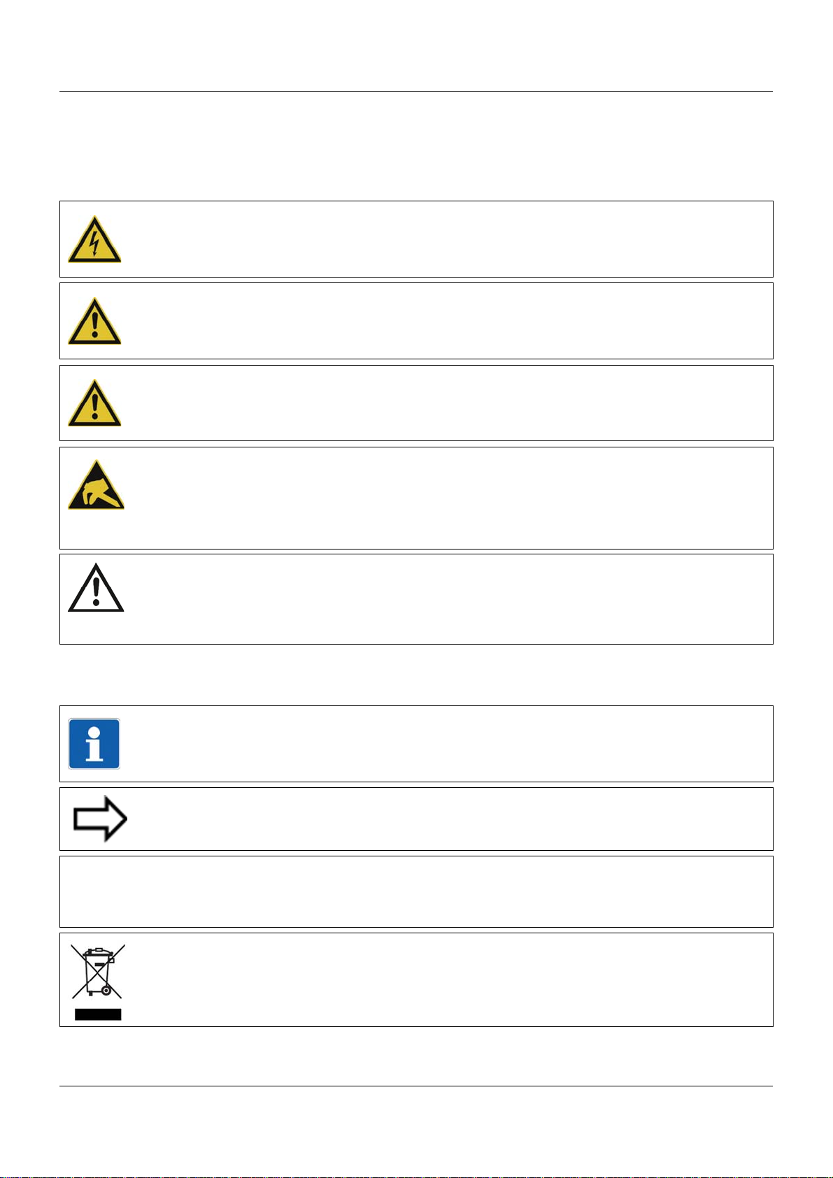
&
1.2.1 Warning symbols
DANGER!
This symbol indicates that personal injury caused by electrical shock may occur if the respective precautionary measures are not carried out.
WARNING!
This symbol in connection with the signal word indicates that personal injury may occur if the
respective precautionary measures are not carried out.
CAUTION!
This symbol in connection with the signal word indicates that damage to assets or data loss
will occur if the respective precautionary measures are not taken.
CAUTION!
This symbol indicates that components could be destroyed by electrostatic discharge
(ESD = Electro Static Discharge) if the respective cautionary measures are not taken.
Only use the ESD packages intended for this purpose to return device inserts, assembly
groups, or assembly components.
1 Introduction
READ DOCUMENTATION!
This symbol – placed on the device – indicates that the associated device documentation
has to be observed. This is necessary to recognize the kind of the potential hazards as
well as the measures to avoid them.
1.2.2 Note signs
NOTE!
This symbol refers to important information about the product, its handling, or additional
use.
REFERENCE!
This symbol refers to further information in other sections, chapters, or manuals.
FURTHER INFORMATION!
This symbol is used in the tables and refers to further information in connection with the
table.
DISPOSAL!
This device and the batteries (if installed) must not be disposed in the garbage can after
use! Please ensure that they are disposed properly and in an environmentally friendly
manner.
11
Page 12

1 Introduction
1.2.3 Intended use
The modules described are intended for measuring, control, an d automation t asks in an ind ustrial environment, as described in the technical data. Oth er uses or uses beyond th ose defined
are not viewed as intended uses.
The modules are built according to the relevant standards and directives as well as the applicable safety regulations. Nevertheless, incorrect use may lead to bodily injury or property damage.
To avoid danger, the modules may only be used:
• For the intended use
• When in good order and condition
• When taking into account the technical documentation provided
Even if a module is used correctly and according to the intended use, it may still cause appli-
cation-related dangers (e.g. due to missing safety devices or incorrect settings).
1.2.4 Qualification of personnel
This document contains the necessary information for the intended use of the modules to which
it relates.
It is intended for technically qualified personnel who have received special training and have
the appropriate knowledge in the field of automation technology (measuring, process, and control technology).
The appropriate level of knowledge and the technically fault-free implementation of the safety
information and warnings contained in the technical documentation provided are prerequisites
for risk-free mounting, installation, and startup as well as for ensuring safety when operating
the described modules. Only qualified personnel have the required specialist knowledge to correctly interpret and implement the safety information and warnings contained in this document
in specific situations.
12
Page 13

1.3 Acceptance of goods, storage, and transport
1.3.1 Checking the delivery
• Ensure that the packaging and contents are not damaged
• Check that the delivery is complete using the delivery papers and the order details
• Inform the supplier immediately if there is any damage
• Store damaged parts until clarification is received from the supplier
1.3.2 Notes on storage and transport
• Store the module in a dry and clean environment. Observe the admissible ambient conditions (see "Technical data")
• The transport of the module is to be shockproof
• The original packaging provides optimum protection for storage and transport
1.3.3 Returning goods
In the event of repair, please return the module in a clean and complete state.
Use the original packaging to return goods.
1 Introduction
Accompanying letter for repair
Please include the completed accompanying letter for repair when returning goods.
Do not forget to state the following:
• Description of the application and
• Description of the error that has occurred
The accompanying letter for repair can be downloaded online from the manufacturer's website
(use the search function if necessary).
Protection against electrostatic discharge (ESD)
(ESD = electrostatic discharge)
To prevent damage from ESD, electronic modules or component s must be handled, packaged,
and stored in an ESD-protected environment. Measures against electrostatic discharge and
electrical fields are described in DIN EN 61340-5-1 and DIN EN 6 1340-5-2 "Protection of electronic devices from electrostatic phenomena".
When returning electronic modules or components, please note the following:
• Sensitive components must only be packaged in an ESD-protected environment. Workspaces such as this divert electrostatic charges to ground in a controlled manner and prevent static charges due to friction capacities.
• Only use packaging for ESD-sensitive modules/components. These must consist of conductive plastics.
No liability can be assumed for damage caused by ESD.
13
Page 14
1 Introduction
CAUTION!
Electrostatic charges occur in non-ESD protected environments.
Electrostatic discharges can damage modules or components.
For transport purposes, use only the ESD packaging provided.
1.3.4 Disposal
Disposing of the device
DISPOSAL!
Devices and/or replaced parts should not be placed in the refuse bin at the end of their service life as they consist of materials that can be recycled by specialist recycling plants.
Dispose of the device and the packaging material in a proper and environmentally friendly
manner.
For this purpose, observe the country-specific laws and regulations for waste treatment a nd
disposal.
Disposing of the packaging material
The entire packaging material (cardboard packaging, inserts, plastic film, and plastic bags) is
fully recyclable.
14
Page 15
1.4 Identifying the device version
(A)
1.4.1 Nameplate
Position
The nameplate (A) is affixed to the case.
1 Introduction
Content
It contains important information. This includes:
Device type
Compare the specifications on the nameplate with the order.
Identify the supplied device version using the order details of the respective module.
Part no. (TN)
The part no. clearly identifies an article in the catalog. It is important for communication
between the customer and the sales department.
Description Designation on the name-
plate
Device type Typ 705060/8-00-00-36/213
Part no. TN 00580746
Fabrication number F-Nr 0070033801211010006
Voltage supply - DC 24 V +25/-20 %
Example
15
Page 16

1 Introduction
Fabrication no. (F-Nr)
Among other things, the fabrication number contains the date of production (year/week).
Example: F-Nr = 0070033801211010006
The figures concerned are in positions 12, 13, 14, and 15 (from the left).
The device was therefore produced in the 1st calendar week of 2011.
16
Page 17

1.4.2 Order details
(1) Basic type
705060 Multifunction panel 840 (1x Ethernet (RJ45), 1x system bus In (RJ45), 1x system bus
Out (RJ45), 2x USB host)
(2) Version
8 Standard, with factory settings
(3) Interface Com1
00 Not used
51 RS232 Modbus RTU
54 RS422/485 Modbus RTU
(4) Interface Com2
00 Not used
51 RS232 Modbus RTU
54 RS422/485 Modbus RTU
(5) Voltage supply
1 Introduction
36 DC 24 V +25/-20 %
(6) Extra codes housing
000 No extra code
444 Stainless steel front with design foil (neutral)
(7) Extra codes
000 No extra code
213 Recording function
(1) (2) (3) (4) (5) (6) (7)
Order code /---/ ,
Order example 705060 / 8 - 00 - 00 - 36 / 000 , 213
1.4.3 Scope of delivery
1 multifunction panel 840 in the ordered version
8 mounting elements
1 strain relief for interface cable
1 template for panel cut-out
1 Installation Instructions B 705060.4
17
Page 18

1 Introduction
1.4.4 Accessories
Article Part no.
Extra codes (activations):
Recording function (extra code 213) 00569508
Additional accessories:
Bar code scanner Gryphon GD4130 00407798
Memory stick USB 2.0 (2 GB)
1
The specified USB memory stick is tested and designed for industrial use. No liability is assumed for
other brands.
1.4.5 General accessories
Article Part no.
JUMO mTRON T system manual, English 00575577
MiniDVD with setup program (full version), programming sof tware CODESYS V3, a nd
detailed documentation; incl. USB cable
PC Evaluation Software PCA3000 00431882
1
00505592
00569494
Release automatic print for PC Evaluation Software PCA3000 00505548
PCA Communication Software PCC 00431879
Plant Visualization Software JUMO SVS3000: See data sheet 700755 USB cable A-plug mini-B-plug 3 m 00506265
1.5 System version
The system version of the measuring, control, and automation system is determined by the
compatibility index of the base unit.
Example composition of a version number for the central processing unit: 248.xx.yy
248 = basic version, xx = compatibility index (system version), yy = current version
In the current document, descriptions that apply only for a particular system version are labeled
accordingly (e.g. "version 02").
18
Page 19
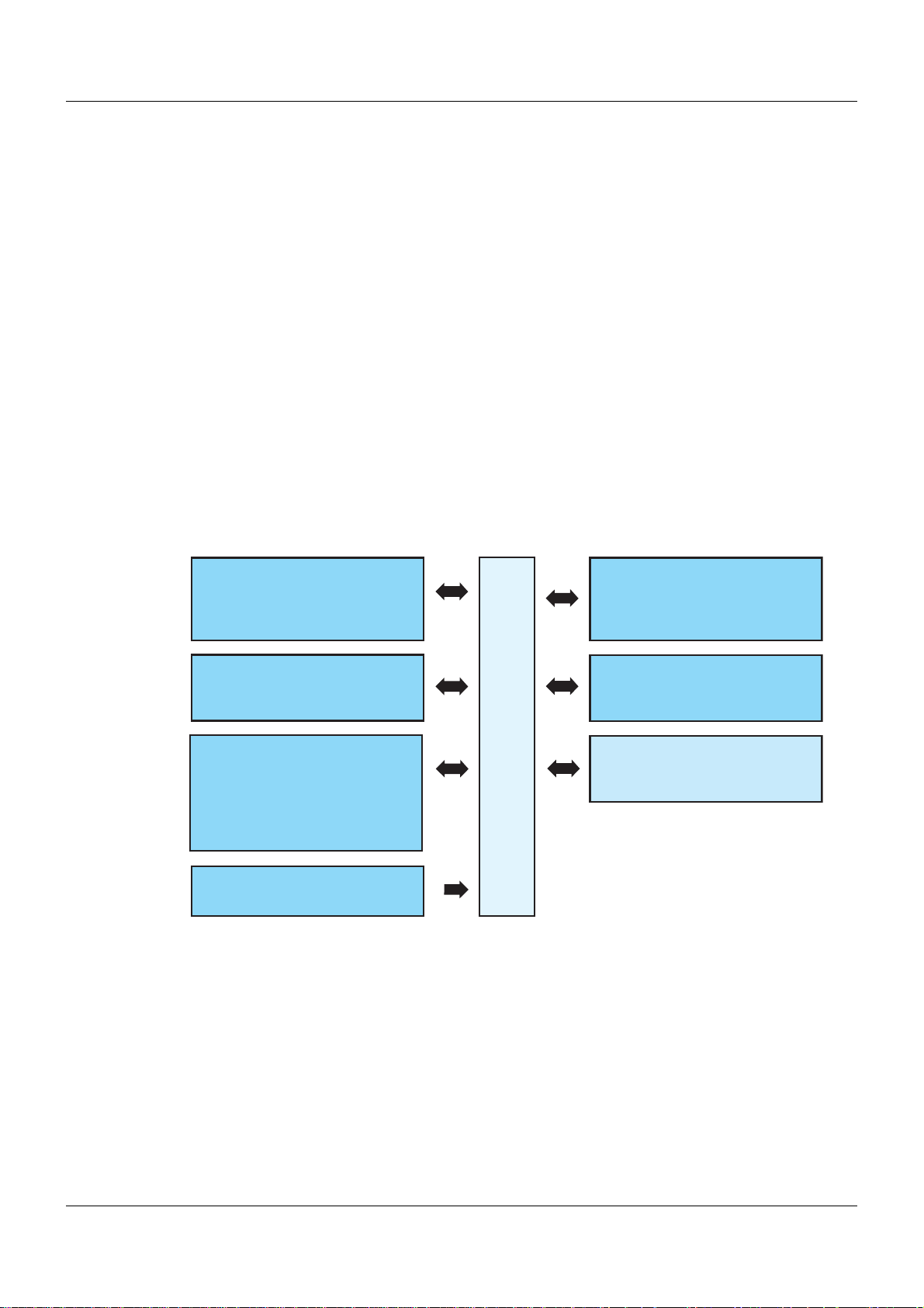
2.1 Brief description
Com1 / Com2
RS232 (Modbus RTU) or
RS422/485 (Modbus RTU)
Voltage supply
Setup
USB device interface
for setup program or
communication software
Bus Out (system bus)
For connection to a router
LAN (Ethernet)
Mainly for use of the
integrated web server,
the setup program,
the visualization software, or
the communication software
Bus In (system bus)
For connection to a base unit
or router
USB1 / USB2
USB host interface
to read data
via memory stick
705060
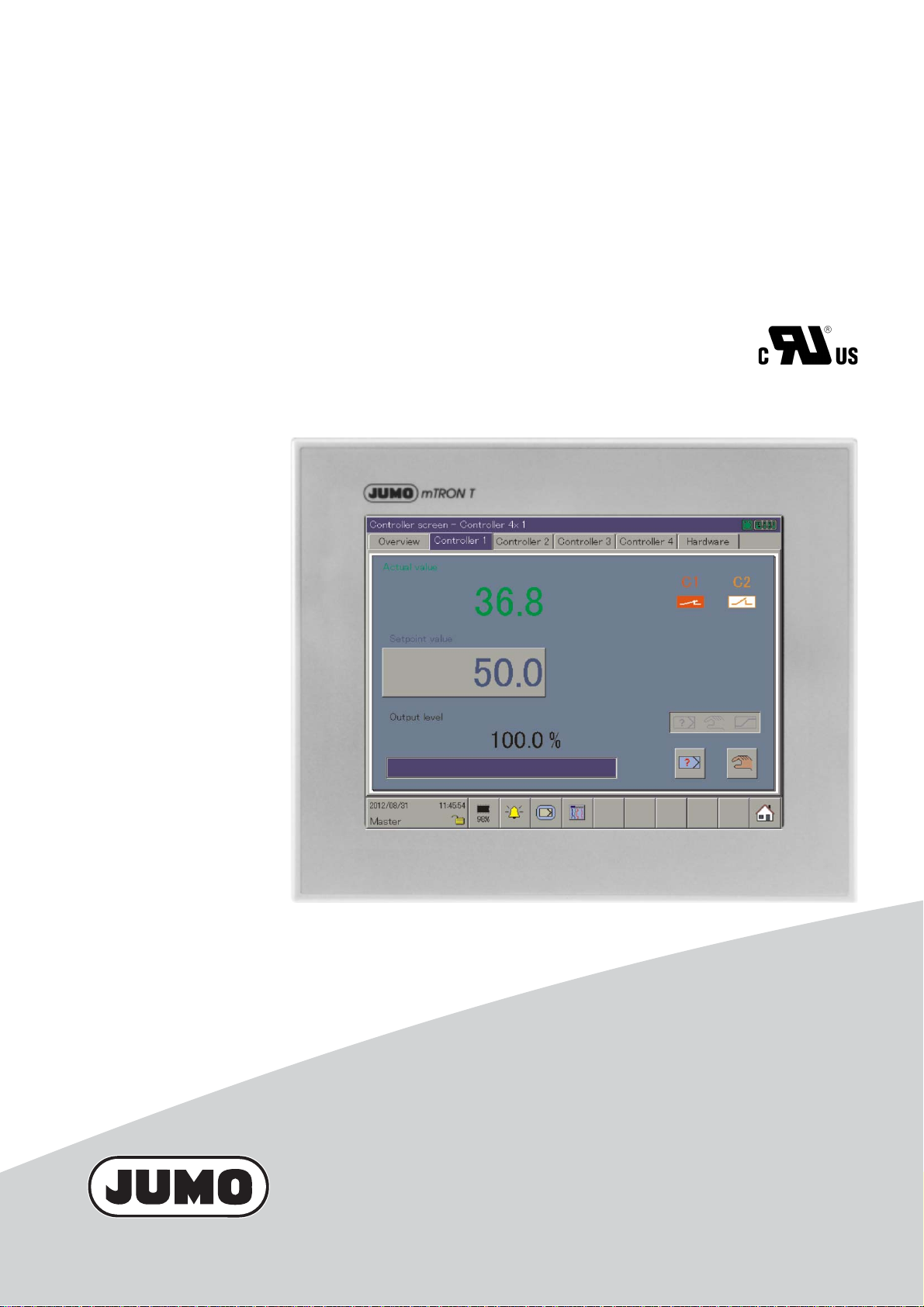
The multifunction panel 840 with TFT -touchscreen allows easy and clearly-arran ged measured
data visualization, operation, configuration, and parameterization of the system.
The TFT color screen has a screen size of 21.3 cm (8.4“), a resolution of 640 × 480 pixels, 256
colors, and LED backlight.
As the interface between man and machine, the panel allows an optimum and clearly-arranged
view of the process status and the system parameters. In addition, it is perfe ctly suitable for the
display and operation of controller screens, process screens, the program editor, and the optional recording function. Setpoint values, batch text, parameters, and configuration data can
be directly entered and changed by the user on the screen.
The process data that is transmitted by the system bus is shown in real time. Data archiving
and evaluation is made possible by established PC-programs.
In addition to the standard interfaces (LAN, USB), two optional serial interfaces can be connected to a barcode scanner, modem, or other Modbus devices (master, slave).
The user can comfortably configure the multifunctional panel 840 with the setup program.
2.2 Block diagram
2 Description
19
Page 20
2 Description
(1) (2)
2.3 Display and control elements
(1) Front with decor foil (2) Screen (touchscreen)
20
Page 21
2.4 Connection elements
(1) (2)
(3)
(4)
(5)
(6)
(7)
(8)
(9)
(10)
(11)
(12)
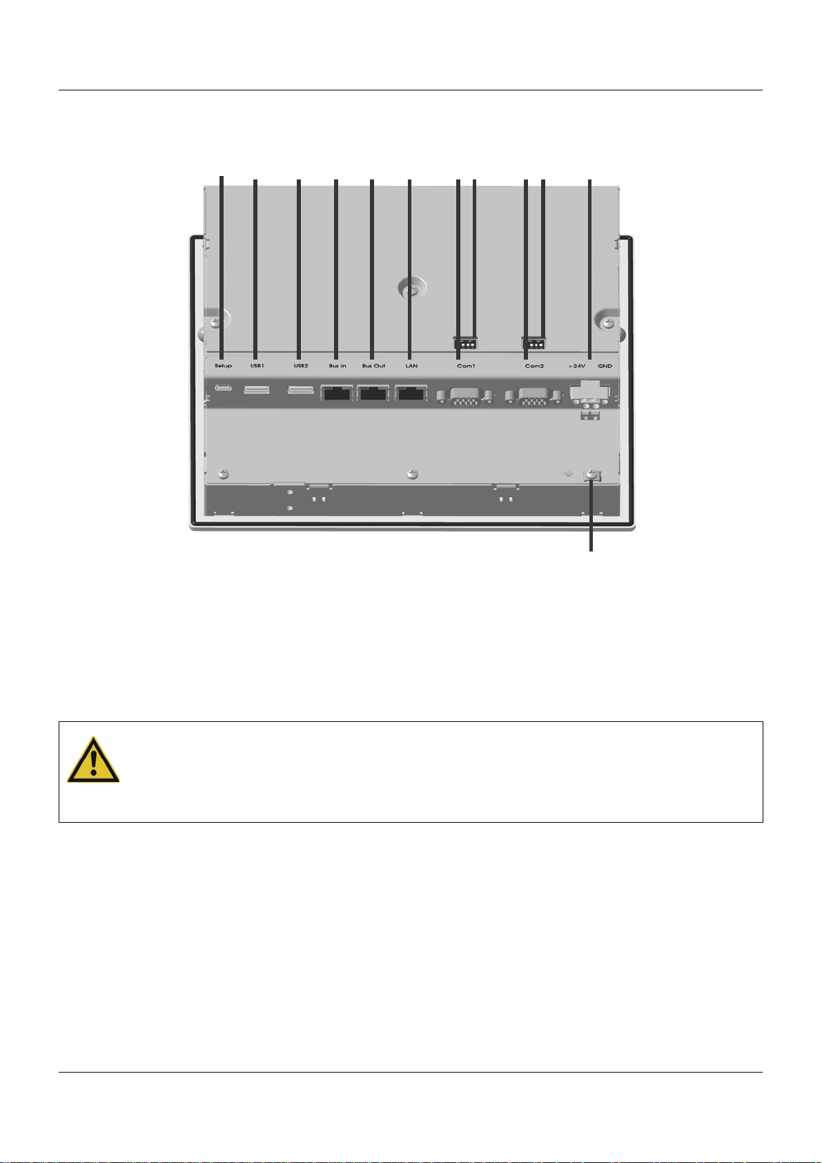
2 Description
(1) USB device interface (setup) (2) USB host interface 1
(3) USB host interface 2 (4) System bus In
(5) System bus Out (6) LAN interface
(7) Com1 interface (8) Com1 terminating resistor
(9) Com2 interface (10) Com2 terminating resistor
(11) Voltage supply In, DC 24 V (12) Functional grounding
CAUTION!
Functional grounding:
Connection terminal for functional ground.
To meet the specified EMC characteristics, this terminal must be connected to functional
ground.
21
Page 22

2 Description
2.5 Use of the interfaces
Interface Used for ...
USB device interface • Setup program
USB host interface 1 • Connection of a USB memory stick
USB host interface 2 • Connection of a USB memory stick
System bus In • Connection to base unit
System bus Out • Connection to router module
LAN interface • Setup program
Com1 interface • Connection to Modbus master device
Com2 interface • Connection to Modbus master device
• Connection to router module
•Web server
• Mail server
• Connection to Modbus slave devices
• Connection of a barcode reader
• Connection of a modem
• Connection to Modbus slave devices
• Connection of a barcode reader
• Connection of a modem
22
Page 23

2.6 Operating modes
NOTE!
The operating modes play a role in the configuration of the groups of the multifunction panel.
This chapter contains the necessary basic knowledge relating to the operating modes.
Chapter 13.11.5 "Standard operation", page 156
Chapter 13.11.6 "Event operation", page 159
Chapter 13.11.7 "Time operation", page 160
NOTE!
Groups can only be configured if the extra code "Registration function" is active.
The user can see whether this extra code is active via the "Device info" function.
If the extra code is not active, the user can subsequently activate this using the setup program.
Chapter 11.1 "Device info", page 102
Setup program:
P
ROJECT > HARDWARE ARRANGEMENT > HMI > GENERAL > OPTIONS
2.6.1 Standard, time, and event operation
2 Description
The operating modes decide the rate at which measurement data is saved.
3 operating modes
The multifunction panel has 3 operating modes:
• Standard operation
• Time operation
• Event operation
The following settings are among those that can be made for each of the three operating
modes:
• Memory values
• Memory rate
Memory values
The "Memory values" parameter specifies whether the average, minimum, maximum, and current values of the period between two memory rates or the peak values (envelope diagram) will
be saved. With the "Min./max. values" setting, the minimum and maximum value of the last
capture period (memory rate) are saved.
An additional option for the "Memory value" parameter is "Eco operation". This is a special
memory mode that is described separately in Chapter 2.6.2 "Eco operation", page 25.
Memory rate
The "Memory rate" parameter specifies the time between 2 saved values. The diagram feed
speed corresponds to the memory rate, i.e. with a memory rate of 5 s, for example, the memory
value will be entered into the diagram every 5 s.
Standard operation
If the multifunction panel is not in event or time operation, standard operation is active.
23
Page 24
2 Description
Time operation
For time operation, the user can enter a time frame (max. 24 hours) during which a specific
memory value and a specific memory rate will be active.
Event operation
Event operation is activated via the control signal, which is assigned e.g. to an event or an
alarm. For example, event operation can be used to reduce the memory rate when an alarm is
activated.
Priority
The priority of the operating modes with regard to one another is allocated as follows:
Operating mode Priority
Standard operation Low
Time operation Medium
Event operation High
Active operating mode
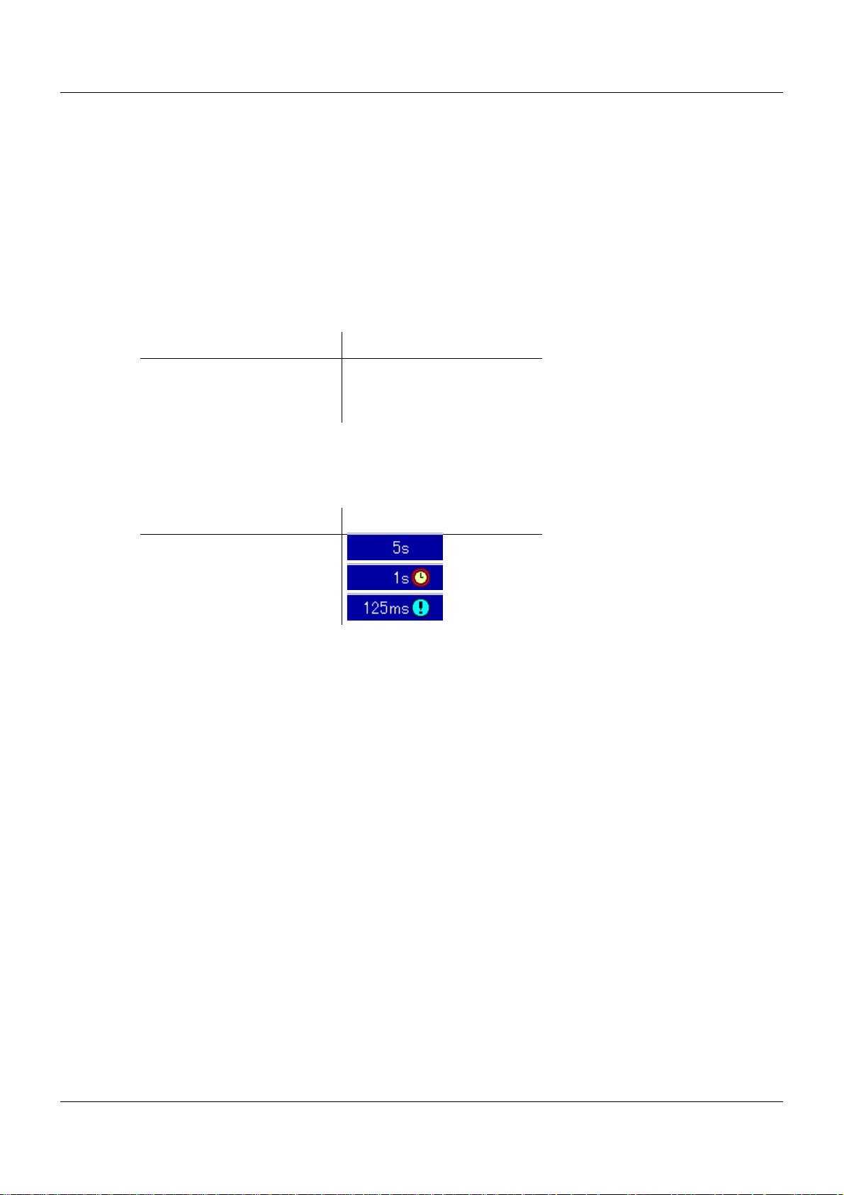
The active operating mode is shown in the diagram using the various symbols after the current
diagram feed speed (memory rate):
Operating mode Symbol
Standard operation
Time operation
Event operation
Memory requirements
A memory space of 130 MB is available for measurement data recording. The space required
depends on the data records which shall be stored. The following information can be used as
a basis for a rough estimate:
• Group of 6 analog inputs and 6 digital inputs, per storage: max. 48 byte
• Group of 6 analog inputs and 6 digital inputs, memory rate 125 ms, per second: 225 byte
• Report, regardsless of the type of report (daily, monthly, ...): 151 byte
• Counter/integrator (at closing): 25 byte
• Batch (at closing): 2 kB
• Alarm/event entry: 6 byte
• Audit-Trail message: 100 byte
Examples for a group of 6 analog inputs and 6 digital inputs:
Memory rate 1 s: 4.1 MB/day; 124 MB/month
Memory rate 30 s: 0.13 MB/day; 4,1 MB/month
(plus memory required for all other data records)
24
Page 25
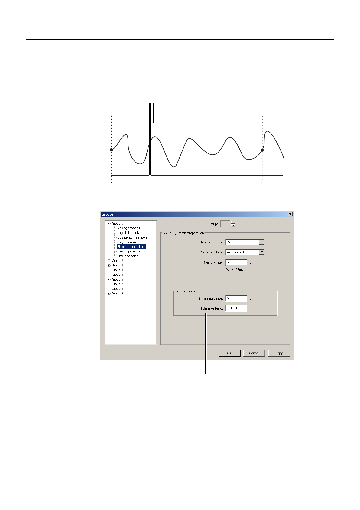
2.6.2 Eco operation
t1 t1
(1)
(1)
The parameters for eco operation are set in the menu for standard operation. However, eco
operation can be used with all three operating modes.
In eco operation, the instantaneous values (current values) are recorded in a specified minimum memory rate (independent of the tolerance band).
(1) Tolerance band
t1 Saving via "Min. memory rate" (controlled save)
2 Description
The value for the tolerance band (1) is stated with regard to the unit of the analog channels (e.g.
± 1 °C). If the measured values exit the tolerance band and if the new measured valu e out side
of the tolerance band is present at least for the duration of the memory rate configured in the
active operating mode, it will be recorded, saved, and provided with a new tolerance band.
25
Page 26
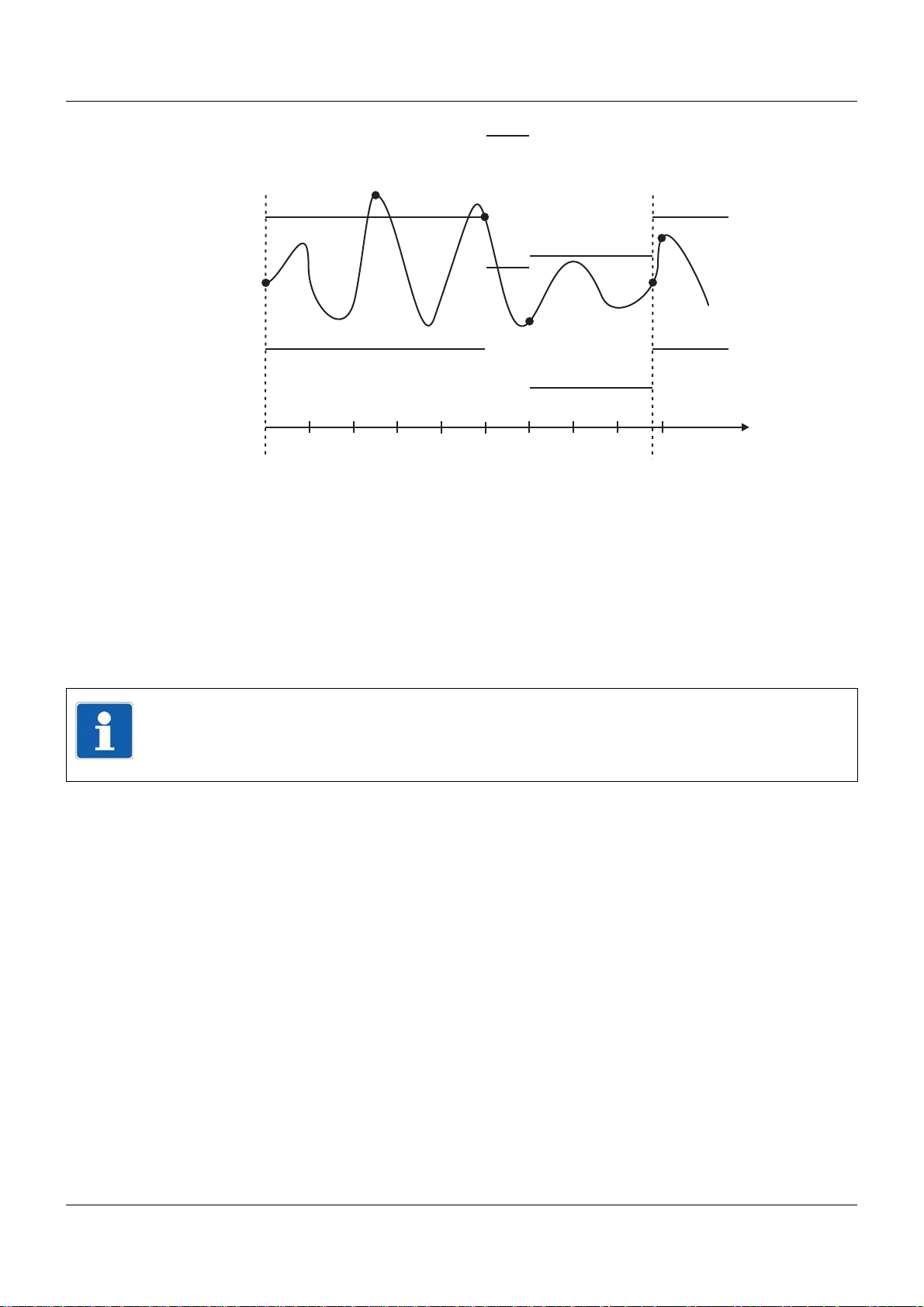
2 Description
10s
10s
10s
10s
10s
10s 10s 10s
t
t1
t2
t3
t4
10s
t6
t5
t1 Saved via "Min. memory rate" (controlled save) and new tolerance band is set.
t2 Not saved, as the measured value at the end of the memory rate (10 s) is once again within the
tolerance.
t3 The new tolerance band is saved and set, as the measured value at the end of the memory rate
had left the tolerance band.
t4 The new tolerance band is saved and set, as the measured value at the end of the memory rate
had left the tolerance band.
t5 Saved via "Min. memory rate" (controlled save) and new tolerance band is set.
t6 Not saved, as the measured value at the end of the memory rate (10 s) is once again within the
tolerance.
NOTE!
It is not mandatory to register when the tolerance band has been exited. If the measured values return to the tolerance band within the memory rate (t2), no registration takes place; the
"Min. memory rate" is always active.
26
Page 27

2.7 Batch reporting
NOTE!
Batch reporting (batches) can also be configured and used without the extra code "Registration function".
A typical application of the batches without the extra code "Registration function " is the transmission of texts to the PLC (central processing unit).
The configuration of the batches is described in the following chapter:
Chapter 13.13 "Batches/Plants", page 165
2.7.1 General information on batches
Batches enable the design of a flexible form for the description of a batch process within the
multifunction panel. A maximum of nine batches can be recorded simultaneously.
The batches can be controlled (start/stop) via one of the digital signals (control signals), via the
touchpad (interface on the screen), or via a barcode scanner.
Further information on control using a barcode reader can be found in:
Chapter 7.8.2 "Batch control via barcode scanner", page 69
2 Description
For batches, a distinction is made between two visualizations. The following are available:
• Current batch report
• Completed batch report
Further information on visualization can be found in:
Chapter 7.8 "Current batch", page 67
Chapter 7.9 "Last completed batch", page 72
27
Page 28
2 Description
(1) (2)
(3)
(4)
(5)
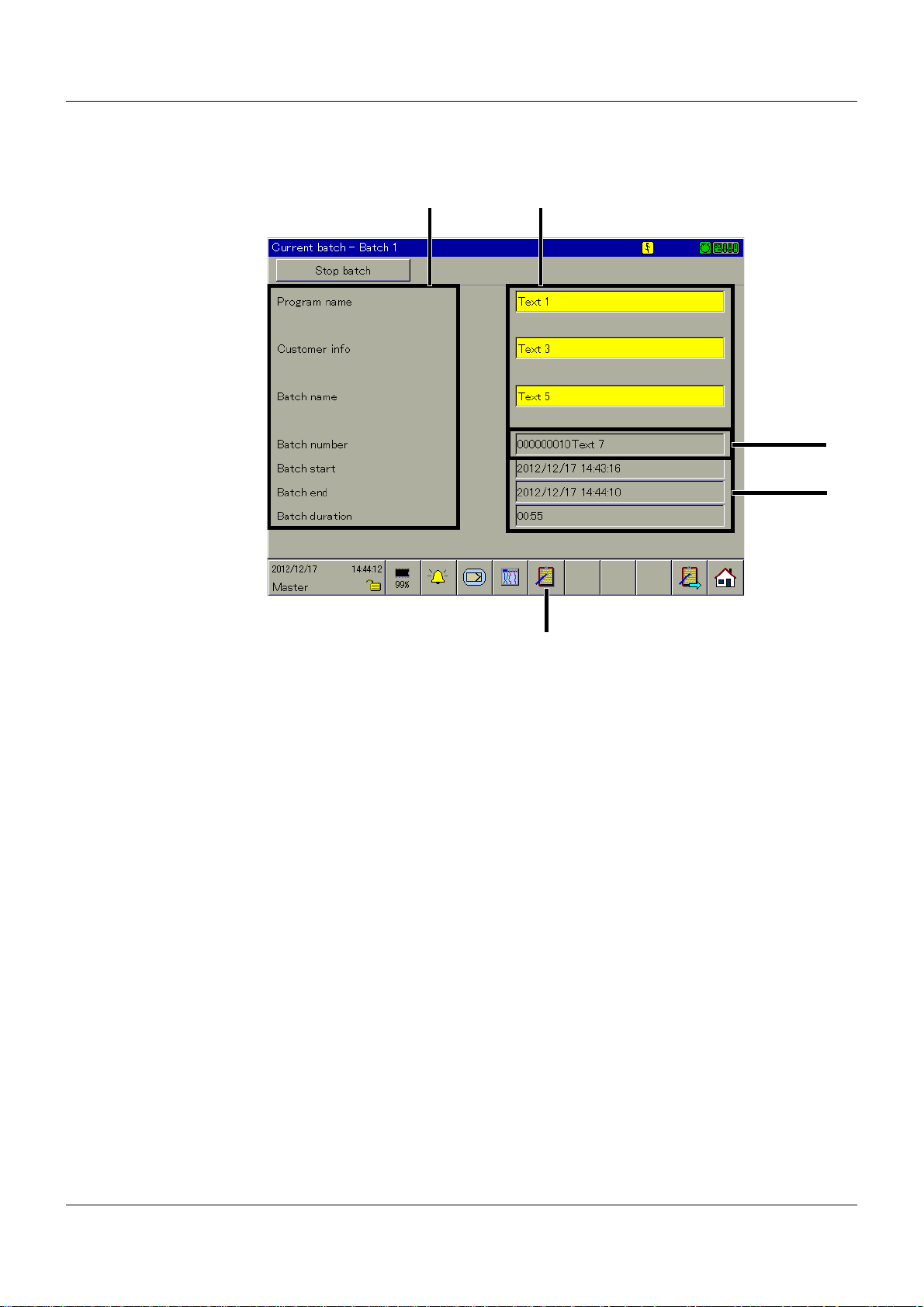
2.7.2 Batch texts
How can something be edited?
(1) Text left column (2) Text right column
(3) Batch number (4) Batch start, end, duration
(5) Batch selection
Text left column
The text in the left column or the left half of the screen can be edited on the multifunction panel
and using the setup program.
Multifunction panel:
C
ONFIGURATION > HMI > BATCHES/PLANTS > BATCH 1 TO 9 > BATCH INFO 1 TO 10 > TEXT
LEFT
Setup program:
HMI > C
INFO
Text right column
The text in the right column or half of the screen can be edited on the multifunction panel and
using the setup program.
Multifunction panel:
C
ONFIGURATION > HMI > BATCHES/PLANTS > BATCH 1 TO 9 > BATCH INFO 1 TO 10 > TEXT
RIGHT
and
C
ONFIGURATION > HMI > BATCHES/PLANTS > BATCH 1 TO 9 > BATCH INFO 1 TO 10 > FACTO-
RY SETTING
COLUMN
ONFIGURATION LEVEL > BATCHES/PLANTS > BATCH 1TO 9 > BATCH INFO > BATCH
1 TO 10 > EDIT > TEXT LEFT COLUMN
COLUMN
28
Page 29

Multifunction panel:
V
ISUALIZATION > CURRENT BATCH
Then change the batch if required and implement the edit by activating the yellow text
1
fields.
Setup program:
HMI > C
INFO
ONFIGURATION LEVEL > BATCHES/PLANTS > BATCH 1TO 9 > BATCH INFO > BATCH
1 TO 10 > EDIT > TEXT RIGHT COLUMN
and
HMI > C
INFO
ONFIGURATION LEVEL > BATCHES/PLANTS > BATCH 1TO 9 > BATCH INFO > BATCH
1 TO 10 > EDIT > FACTORY SETTING
Batch number
Permanent changes to the batch number can only be made on the multifunction panel.
Multifunction panel:
P
ARAMETERIZATION > HMI > BATCHES/PLANTS > BATCH NUMBER 1 TO 9
It can be temporarily changed on the multifunction panel;
HMI batch number will be incremented and reactivated.
Batch start, end, duration
If the batch start, end, and duration are used, the lines can no longer be edited.
2 Description
2
at the end of a batch, the internal
Batch selection
This function is used to directly select and display one of the active batches. Simply touch one
of the batch names displayed after calling up the function.
NOTE!
The function is only available if more than one batch is active.
1
Only available if the respective batch parameter "Editable?" is set to Yes.
2
Only available if the respective batch parameter "Editable?" is set to Yes.
29
Page 30

2 Description
30
Page 31

3 Installation
3.1 General information on installation/dismounting
DANGER!
With multichannel controller module 705010 and relay module 705015, the load circuits from
relay or solid state relay outputs can be operated with a dangerous electrical voltage (e.g.
230 V).
There is a risk of electric shock.
Prior to the installation/dismounting of these modules or the removal of the module insert, the
load circuits are to be disconnected from the voltage and the terminal strips are to be removed from the module. This work must only be performed by qualified personnel.
WARNING!
The modules must never be installed in areas with an explosion hazard.
There is the risk of an explosion.
The entire system must only be used outside of areas with an explosion hazard.
Mounting site
All modules have protection type IP20 and are only intended for use in fireproof con trol cabinets
or switch boxes. The mounting site should be virtually vibration-free. Electromagnetic fields
caused by equipment such as motors or transformers should be avoided.
Multifunction panel 840 has protection type IP67 at the front and is intended for installation in
a panel cut-out. The rear has protection type IP20.
Climatic conditions
The ambient temperature and the relative humidity at the mounting site must correspond to the
technical data. Aggressive gases and vapors have a negative ef fect on the operating life of the
modules. The mounting site must be free from dust, powder, and other suspended matter so
that the cooling slots do not become blocked.
DIN rail
All modules are mounted on a DIN rail according to DIN EN 60715 (35 mm × 7.5 mm × 1 mm).
For reasons of stability, the spacing of the fastening screws for the DIN rail should not exceed
200 mm. The minimum distances for the modules that are specified in the module-specific installation or operating instructions must be observed.
Installation position
The DIN rail should be mounted horizontally so that all modules are arranged vertically. Otherwise the admissible ambient temperature range will be restricted.
Space requirement
The modules require the minimum distances shown in the following figure for the purpose of
installation/dismounting and for future maintenance or replacement. In the event of shorter distances the minimum bending radius of the cables, the performance of the electrical inst allation,
and the clear arrangement of the plant are no longer guaranteed.
31
Page 32

3 Installation
(A)
(B)
(B2)
(A1)
(C)
(C)
(C3)
(C3)
(D)
(D4)
(C)
(C)
(C)
(C)
(C)
(C)
(C3)
(C3)
(C3)
(C3)
(C3)
(C3)
(B2)
(B)
3.2 Mounting in a panel
3.2.1 Multifunction panel
Mounting a multifunction panel 840 (705060)
Procedure:
Step Activity
1 Insert the device (A) into the panel cut-out (A1) fr om the fron t until the two side spr ing balls
(B) click into place (B2). The spring balls facilitate the mounting, but do not replace the fastening elements (step 2).
2 Insert the fastening elements (C) into the recesses of the case (C3) and use a screwdriver
(D) to evenly clamp them against the rear side of the panel with a torque of 0.5 Nm (D4).
NOTE!
The provided template is to be used to create the panel cut-out. This is the only way to guarantee optimum positioning of the multifunction panel.
32
Page 33

3.3 Strain relief for interface cable
(A)(B)
(B)
3 Installation
(A) Panel for strain relief (B) Fastening screws
Procedure:
Step Activity
1 Loosen the fastening screws (B) (do no t re mo ve ).
2 Place the panel for strain relief (A) on the case and retighten the fastening screws (B).
NOTE!
The interface cables can be attached to the panel using cable ties for strain relief.
NOTE!
If the cable shield is connected to the case of the multifunction panel, the exterior sheathing
of the interface cable must be removed at the location of the strain relief.
33
Page 34

3 Installation
195
219
31
51
179
3.4 Dimensions
34
Page 35

4.1 Installation notes
NOTE!
These installation notes apply for the entire measuring, control, and automation system and,
on some occasions, are only applicable for a specific module.
The respective connection diagram shows the context.
Requirements for the personnel
• Work on the modules must only be carried out to the extent described and, like the electrical
connection, only by qualified personnel.
• Before plugging and unplugging connection cables ensure that the person performing the
work is electrostatically discharged (e.g. by touching grounded metallic parts).
Cables, shielding, and grounding
• When selecting the cable material, when installing, and when performing the electrical connection of the module, the regulations of DIN VDE 0100 "Erection of power installations with
rated voltages up to 1000 V" and the respective national regulations (e.g. on the basis of
IEC 60364) are to be observed.
• Certain cables must be heat resistant up to at least 80 °C at maximum load. The relevant
instructions in the connection diagram of the affected modules must be observed.
• Route input, output, and supply cables separately and not parallel to one another.
• Only use shielded and twisted probe and interface cables. Do not route the lines close to
current-carrying components or cables.
• For temperature probes, ground the shielding on one side in the control cabinet.
• Do not perform loopthroughs on the grounding cables, but route the cables individually to a
shared grounding point in the control cabinet; in doing so, ensure that the cables are as
short as possible.
Ensure that the equipotential bonding is correct.
4 Electrical connection
Electrical safety
• Isolate power supply units from the voltage supply on the primary side if there is a risk of
touching parts with dangerous electrical voltage (e.g. 230 V) in the course of work.
• The fuse rating of the power supply units on the primary side should not exceed a value of
10 A (inert).
• With modules with relay or solid state relay outputs, the load circuits can be operated with
a dangerous electrical voltage (e.g. 230 V). Disconnect load circuits from the voltage supply
during installation/dismounting and electrical connection.
• In order to prevent the destruction of the relay or solid state relay outputs in the event of an
external short circuit in the load circuit, the load circuit should be fused to the maximum admissible output current.
• The modules are not suitable for installation in areas with an explosion hazard.
• In addition to a faulty installation, incorrectly set values on the module could also impair the
correct function of the following process. Therefore, ensure that safety devices independent
of the module (e.g. overpressure valves or temperature limiters/monitors) are available and
that it is only possible for qualified personnel to define settings. Please observe the corresponding safety regulations in this context.
35
Page 36

4 Electrical connection
USB device
interface
System bus In
Interface Com2
»
Voltage supply
DC 24 V
Interface Com1
»
AC 1500 V
»
AC 1000 V
System bus Out
AC 1500 V
LAN
AC 1500 V
AC 30 V
DC 50 V
AC 30 V
DC 50 V
USB host
interface 1
USB host
interface 2
References to other information
• The electromagnetic compatibility meets the standards and regulations cited in the technical data.
• The USB device interface and voltage supply in the central processing unit 705001 are not
electrically isolated. In general, please observe the specifications regarding electrical isolation.
4.2 Electrical isolation
36
Page 37

4.3 Connection diagram
(1) (2)
(3)
(4)
(5)
(6)
(7)
(8)
(9)
(10)
(11)
(12)
CAUTION!
At maximum load, the temperature at the "+24 V" and "GND" terminals (Voltage supply In)
may exceed 60 °C.
As a result the insulation of the cable may be damaged.
The cable must be heat resistant up to at least 80 °C.
4.3.1 Connection elements
4 Electrical connection
(1) USB device interface (setup) (2) USB host interface 1
(3) USB host interface 2 (4) System bus In
(5) System bus Out (6) LAN interface
(7) Com1 interface (8) Com1 terminating resistor
(9) Com2 interface (10) Com2 terminating resistor
(11) Voltage supply In, DC 24 V (12) Functional grounding
CAUTION!
Functional grounding:
Connection terminal for functional ground.
To meet the specified EMC characteristics, this terminal must be connected to functional
ground.
37
Page 38

4 Electrical connection
8
1
8
1
6
7
8
9
2
3
4
5
1
6
7
8
9
2
3
4
5
1
6
7
8
9
2
3
4
5
1
4.3.2 Interfaces
Connection Designation Connection element
USB device Setup
USB host USB1,
USB2
System bus In,
System bus Out
Bus In,
Bus Out
1 TX+
2 TX3 RX+
6 RX-
Ethernet LAN 1 TX+
2 TX3 RX+
6 RX-
Serial interface
(RS232),
optional
Serial interface
(RS422),
optional
Com1,
Com2
Com1,
Com2
2 RxD
3 TxD
5 GND
3 TxD+
4 RxD+
5 GND
8 TxD9 RxD-
Serial interface
(RS485),
optional
Com1,
Com2
3 TxD+/RxD+
5 GND
8 TxD-/RxD-
Transmit data +
Transmit data Receive data +
Receive data -
Transmit data +
Transmit data Receive data +
Receive data -
Receive data
Transmit data
Ground
Transmit data +
Receive data +
Ground
Transmit data Receive data -
Transmit/receive data +
Ground
Transmit/receive data -
38
Page 39

4.3.3 Terminating resistors
2
1
3
4
ON
332 ?
120 ?
332 ?
GND
+5 V
4
9
332 ?
120 ?
332 ?
GND
+5 V
3
4
3
8
1
2
U
+
-
x
The internal terminating resistors for the Com1 and Com2 interfaces are only relevant for
RS422/485.
The terminating resistors are deactivated by default. To activate them, DIP switches 1 to 4 for
the relevant interface must be pushed upward using a suitable tool such as a ballpoint pen (ON
position).
The following figure shows the position of the DIP switches when the terminating resistors are
activated.
NOTE!
To ensure fault-free operation, terminating resistors are required at the start and end of an
RS422/485 transmission path.
Internal terminating resistors
4 Electrical connection
4.3.4 Voltage supply
Connection Terminals Symbol and terminal designation
24 V DC +24 V and GND +24 V
GND
39
Page 40

4 Electrical connection
4.4 Functional test
Once the electrical connection is complete, the following points must be checked:
1) Voltage supply
2) Connection to system bus
3) Errors during initialization
Voltage supply
If Then
the voltage supply is present • the multifunction panel starts.
Connection to system bus
The "Bus In" input must be connected to a "Bus Out" output of a base unit or a router module.
Errors during initialization
If errors occur during the initialization, the user must monitor the configuration of the system
using the setup program and rectify errors.
• the screen shows a start picture.
Startup
The checks described above complete the process of installation and electrical connection. For
startup, use the additional documentation (operating manual or system manual).
The "Introduction" chapter of this document contains an overview of all documentation for the
measuring, control, and automation system.
40
Page 41

5.1 Operating concept and graphic elements
(1)
(2)
(3)
Operating concept
The operating concept of the multifunctional panel is as clear and simple as you could imagine.
The user controls the panel by touching the screen (touchscreen) with a fingertip.
5 Operation
(1) Status and title line (2) Visualization window
(3) Function selection
NOTE!
Do not use any objects that are sharp or have sharp edges, otherwise the screen may be
scratched.
41
Page 42

5 Operation
(1) (2) (3)
(2)
5.1.1 Status line and Title line
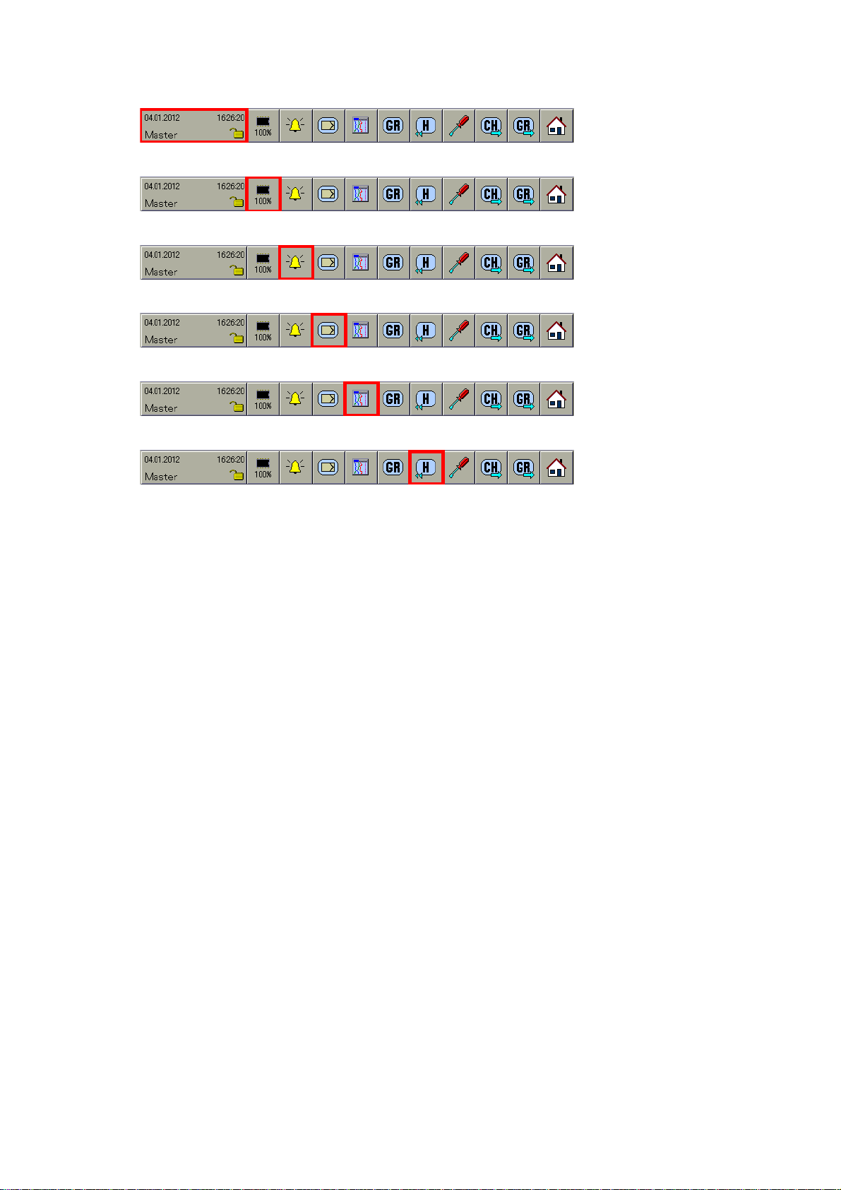
This line displays alarm and error messages as well as general information on the active display (e.g. sampling rate). It is automatically hidden by the system if required.
(1) Area for text and error messages; if the text
is displayed with a red background, it
relates to an alarm (error message)
(3) Area for symbols relating to communication
with other modules
Symbol (2) Meaning
Sampling rate (5 s) and operating mode (standard operation)
Sampling rate (125 ms) and operating mode (event operation)
Sampling rate (1 s) and operating mode (time operation)
Data read-out is currently being performed by the PCA communication software
PCC.
Symbol (3) Meaning
Base unit is in RUN status
Base unit is in STOP status
Communication with base unit not interrupted
Communication with base unit interrupted
Communication with base unit interrupted
(2) Area for symbols relating to the panel
42
NOTE!
If the text is displayed with a read background, it relates to an error message.
Page 43

5.1.2 Visualization window
(1)
(2)
The visualization of the measuring data and control data takes place in this area of the screen
(underneath the status and title line and above the function selection). The area for the configuration of the system will continue to be used.
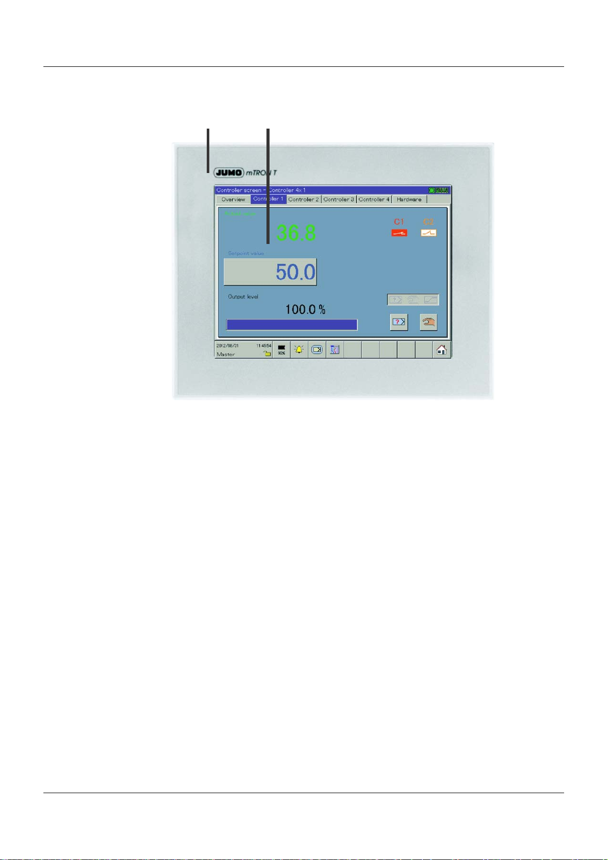
Example: Visualization of a controller (controller screen)
5 Operation
Example: Visualization of an analog channel
(1) Diagram header (2) Diagram
43
Page 44

5 Operation
(1)
(1)
Diagram header
The diagram header (the numerical measured value display on the screen) is displayed directly
underneath the status and title line and is available in the following display types:
•Diagram
• History (of diagram display)
•Digital
The diagram header can be switched on and off.
(1) Alarm
NOTE!
A channel alarm is marked orange (Alarm1) or red (Alarm2).
The colors can be configured in the setup program.
Diagram
Under History (for the diagram display), the user can switch between the min. and max. display
if the diagram header is switched on. Whether the min. and max. values are available simultaneously depends on the current operating mode setting of the group.
Diagram header in the Diagram visualization:
Diagram header in the digital visualization:
44
(1) Symbols
In the area of the diagram (graphic measured value display), various symb ols are displa yed in
addition to the measurement data. Alarm diagrams are marked red or orange (this can be configured using the setup program).
Page 45

Symbol Meaning
(1)
(2)
(3)
(1) (2) (3) (4) (5) (6) (7) (8) (9) (10) (11)
Comment was entered
Event has occurred
Alarm no longer present (on multifunction panel)
Alarm was reported (on multifunction panel)
Event has occurred (on base unit)
In addition, the communication with the operator (device configuration, inspection of alarm and
event lists, etc.) is performed in the visualization window.
5.1.3 Function selection
5 Operation
(1) Set functions (2) Variable functions with changing symbols
(3) Function is performed if the user touches
the screen
The functions of the multifunction panel are selected in the function selection area. The symbols in area (2) change depending on the function performed.
The function selection of the normal display is subsequently shown if the vertical diagram (diagram display) has been selected.
(1) Device manager (2) Memory manager
(3) Alarm and event lists (4) Controller
(5) Visualization
(visualization of current data)
(7) Memory display (History) (8) Diagram view
(9) Channel rotation (10) Group rotation
(1 1) Normal display (Home)
(6) Group selection
NOTE!
If not all functions can be selected, the functions must first be released by changing the configuration. The setup program may be required for this purpose.
45
Page 46

5 Operation
5.2 Operation example
Start
An analog channel is displayed.
Operation
Step Activity
1 Select the Visualization menu by touching the touchscreen.
➥ The "Visualization" menu is shown.
46
Page 47

Step Activity
2 Select bar graph display by touching the touchscreen.
5 Operation
➥ The "Bar graph" display mode is started.
47
Page 48

5 Operation
48
Page 49

6 Multichannel controller module
(1)
(2)
(3)
This chapter describes the visualization and operation of the control channels and the program
generator.
Select the multichannel controller module or the program generator
The multichannel controller module or the program generator is selected via the button that is
highlighted.
(1) Exit function (2) Program generator
(3) Multichannel controller module (controller
Exit function
Touch the screen here to exit the function and return to the visualization from which it was
called up.
Prog. generator
After this function is called up, an overview of the nine program generators will be shown.
Touching an entry will open the corresponding generator screen.
The operation of the program generators is described in operating manual B 705001.0
(central processing unit).
The program generators can also be controlled by a barcode scanner (select program number ,
start and stop program).
Chapter 16.2.3 "Program generator control", page 268
screen)
49
Page 50

6 Multichannel controller module
Multichannel controller module (controller screen)
If only one controller channel is configured, then the corresponding controller screen will be displayed immediately.
If multiple controller channels are configured, an overview of the active controller channels will
be shown. Selecting a controller channel also opens the corresponding controller screen.
The operation of the controller channels is described in operating manual B 705010.0 (mul-
tichannel controller module).
50
Page 51

Selecting visualization
The type of visualization (diagrams, bar graph, etc.) is initiated using the button shown above.
The following maximum selection of visualizations is available.
7 Visualization
Step Activity
1 Select the desired visualization by touching the screen.
➥ The visualization is displayed.
Example: Diagram
The available functions at the bottom of the screen vary depending on the visualization selected.
51
Page 52

7 Visualization
7.1 Function overview
Diagram
Chapter 7.2 "Diagram", page 54
Bar graph
Chapter 7.3 "Bar graph", page 56
Text image
Chapter 7.4 "Text image", page 58
Process screen
Chapter 7.5 "Process screen", page 62
Digital
Chapter 7.6 "Digital", page 63
Reports
Chapter 7.7 "Reports", page 65
Current batch
Chapter 7.8 "Current batch", page 67
Completed batches
52
Chapter 7.9 "Last completed batch", page 72
Page 53

Counters/Integrators
Chapter 7.10 "Counters/Integrators", page 76
User operating level
Chapter 7.11 "User operating level", page 79
Enter comments
There is no separate function selection for entering comment s. The current one is retain ed until
the function is called up. The comment entered is recorded in the event list.
Chapter 7.12 "Enter comments", page 80
NOTE!
The first five functions in the function selection (from the left) are the same in all five visualizations. These relate to superordinate functions. Changes can only be made to the final six
functions.
7 Visualization
53
Page 54

7 Visualization
(1)
(2)
(3)
(5) (6) (7) (8) (9) (10)
(4)
7.2 Diagram
In this visualization, the individual signals run across the screen from top to bottom (vertical display).
(1) Alarm (2) Operating mode
(3) Alarm (4) Communication status
(5) Group selection (6) Memory display
(7) Numerical measured value display (8) Channel rotation
(9) Group rotation (10) Home button
Alarm
An alarm (Alarm1 or Alarm2) is marked with an orange or red background and an orange or
red diagram. The colors can be configured in the setup program and using the multifunction
panel.
Sampling rate and operating mode
Chapter 5.1.1 "Status line and Title line", page 42
Communication status
Chapter 5.1.1 "Status line and Title line", page 42
54
Page 55

Group selection
(1) (5)(2)
(3) (4)
(1)
This function is used to directly select and display one of the active groups. Simply touch one
of the group designations displayed after calling up the function.
NOTE!
The function is only available if more than one group is active.
Memory display
This function is used to start the display of the data available in the history memory.
Chapter 8 "Memory display (History)", page 83
Numerical measured value display
This function can be used to show and hide the numerical measured value display (diagram
header) and the digital tracks, and to activate the envelope diagram display.
Chapter 5.1.2 "Visualization window", page 43
Channel rotation
This function activates the display of various limits. Touching the button repeatedly shifts the
channel limits within the group and then subsequently hides them.
7 Visualization
NOTE!
The function is only available if more than one analog channel is active in a group.
Group rotation
In contrast to the "Group selection" function, in which any group can be selected, this function
displays the groups one after the other.
NOTE!
The function is only available if more than one group is active.
(1) Range start (2) Limit value 1
(3) Current measured value (4) Limit value 2
(5) Range end (6) Memory display
(1) Group number
55
Page 56

7 Visualization
(1)
(3)
(6) (7) (8)
(2)
(5)
(4)
Home button
This function calls up a defined visualization. The function must be activated and configured
via the setup program.
Setup program:
HMI > C
7.3 Bar graph
In this visualization, the analog channels are displayed numerically and as a bar graph (columns). In addition to the analog channels, the digital channels are displayed at the bottom of
the screen.
ONFIGURATION LEVEL > SCREEN > USER OPERATING LEVEL
(1) Alarm (2) Communication status
(3) Limit value 1 (4) Alarm
(5) Limit value 2 (6) Group selection
(7) Group rotation (8) Home button
NOTE!
If only the digital channels are to be shown, the "Digital" visualization is recommended.
Chapter 7.6 "Digital", page 63
Alarm
An alarm (Alarm1 or Alarm2) is marked with an orange or red background and an orange or
red bar. The colors can be configured in the setup program and using the multifunction panel.
Communication status
Chapter 5.1.1 "Status line and Title line", page 42
56
Page 57

Group selection
(1)
This function is used to directly select and display one of the active groups. Simply touch one
of the group designations displayed after calling up the function.
NOTE!
The function is only available if more than one group is active.
Group rotation
In contrast to the "Group selection" function, in which any group can be selected, this function
displays the groups one after the other.
(1) Group number
NOTE!
The function is only available if more than one group is active.
7 Visualization
Home button
This function calls up a defined visualization. The function must be activated and configured
via the setup program.
Setup program:
HMI > C
ONFIGURATION LEVEL > SCREEN > USER OPERATING LEVEL
57
Page 58

7 Visualization
(5) (7) (8)
(3)
(4)
(1)
(2)
(6)
7.4 Text image
In this visualization, the analog channels are displayed numerically together with the channel
designation and the channel description. In addition to the analog channels, the digital channels can be visualized on the right side of the screen.
7.4.1 Group display
(1) Channel name (2) Channel description
(3) Communication status (4) Alarm
(5) Group selection (6) Channel display
(7) Group rotation (8) Home button
Communication status
Chapter 5.1.1 "Status line and Title line", page 42
Alarm
Group selection
An alarm (Alarm1 or Alarm2) is marked with an orange or red background. The colors can be
configured in the setup program and using the multifunction panel.
This function is used to directly select and display one of the active groups. Simply touch one
of the group designations displayed after calling up the function.
NOTE!
The function is only available if more than one group is active.
58
Page 59

Channel display
(1)
The function switches to the channel display.
Chapter 7.4.2 "Channel display", page 60
Group rotation
In contrast to the "Group selection" function, in which any group can be selected, this function
displays the groups one after the other.
(1) Group number
NOTE!
The function is only available if more than one group is active.
Home button
This function calls up a defined visualization. The function must be activated and configured
via the setup program.
Setup program:
HMI > C
7 Visualization
ONFIGURATION LEVEL > SCREEN > USER OPERATING LEVEL
59
Page 60

7 Visualization
(7) (9) (10)
(3)
(6)
(1)
(2)
(8)
(5)
(4)
7.4.2 Channel display
(1) Channel name (2) Channel description
(3) Communication status (4) Limit value 2
(5) Limit value 1 (6) Alarm
(7) Channel selection (8) Group display
(9) Channel rotation (10) Home button
Communication status
Chapter 5.1.1 "Status line and Title line", page 42
Alarm
An alarm (Alarm1 or Alarm2) is marked with an orange or red background. The colors can be
configured in the setup program and using the multifunction panel.
Channel selection
This function is used to select and display one of the active analog channels. Simply touch one
of the channel names displayed after calling up the function.
NOTE!
The function is only available if more than one analog channel is active in the selected group.
Group display
The function switches to the group display.
Chapter 7.4.1 "Group display", page 58
60
Page 61

Channel rotation
In contrast to the "Channel selection" function, in which any channel can be selected, this function displays the channels one after the other.
NOTE!
The function is only available if more than one analog channel is active in the selected group.
Home button
This function calls up a defined visualization. The function must be activated and configured
via the setup program.
Setup program:
HMI > C
7 Visualization
ONFIGURATION LEVEL > SCREEN > USER OPERATING LEVEL
61
Page 62

7 Visualization
(2)
(4)
(1)
(3)
7.5 Process screen
In this visualization, selected measurement signals and backgrounds are displayed in a maximum of 18 process screens. The screens are prepared and configured using the setup program.
Scope per process screen:
• 1 background image, 640 × 480 pixels, max. 256 colors
• 150 objects, such as analog and digital signals, icons, texts, bar graphs, and switch elements
Setup program:
HMI > S
ETUP ONLY > PROCESS SCREENS
(1) Communication status (2) Example: T ext a nd a nalo g channe l (numer i-
(3) Example: Text and analog channel (bar
graph)
NOTE!
In the visualization of analog channels in the process screen, there is no color change in the
event that a limit value is not reached or is exceeded. A color change can be realized, however, with the PLC function (extra code 224 required for central processing unit 705001).
Communication status
Chapter 5.1.1 "Status line and Title line", page 42
Home button
This function calls up a defined visualization. The function must be activated and configured
via the setup program.
62
cal)
(4) Home button
Page 63

Setup program:
(1)
(3) (4) (5) (6) (7)
(2)
HMI > C
7.6 Digital
In this visualization, only the digital channels are displayed; the analog channels are not shown.
7 Visualization
ONFIGURATION LEVEL > SCREEN > USER OPERATING LEVEL
(1) Operating mode (2) Communication status
(3) Group selection (4) Memory display
(5) Numerical measured value display (6) Group rotation
(7) Home button
Sampling rate and operating mode
Chapter 5.1.1 "Status line and Title line", page 42
Communication status
Chapter 5.1.1 "Status line and Title line", page 42
Group selection
This function is used to directly select and display one of the active groups. Simply touch one
of the group designations displayed after calling up the function.
NOTE!
The function is only available if more than one group is active.
Memory display
This function is used to start the display of the data available in the history memory.
63
Page 64

7 Visualization
(1)
Chapter 8 "Memory display (History)", page 83
Numerical measured value display
This function can be used to show and hide the numerical measured value display (diagram
header) and the digital tracks, and to activate the envelope diagram display.
Chapter 5.1.2 "Visualization window", page 43
Group rotation
In contrast to the "Group selection" function, in which any group can be selected, this function
displays the groups one after the other.
(1) Group number
NOTE!
The function is only available if more than one group is active.
Home button
This function calls up a defined visualization. The function must be activated and configured
via the setup program.
Setup program:
HMI > C
ONFIGURATION LEVEL > SCREEN > USER OPERATING LEVEL
64
Page 65

7.7 Reports
(2)
(3)
(5)
(9) (10) (11) (12)
(4)
(1)
(6)
(7)
(8)
This lists every report on all of the analog channels in a group. Each group has its own configurable report.
7 Visualization
(1) Current report (2) Type of report
(3) Completed report (4) Communication status
(5) Maximum (6) Minimum
(7) Average (8) Period
(9) Group selection (10) Channel rotation
(11) Group rotation (12) Home button
Current report
The report data of the current capture period is displayed in this area. The title of the report is
composed of the channel name and the report type.
Type of report
This function is used to switch between the individual report types for the current channel. To
display a different report type, the user simply needs to touch the corresponding button (in this
example, from "Total" to "Extern").
Completed report
The report data of the previous capture period is displayed in this area.
Maximum
The current maximum value of the current capture period is displayed in this area. In addition
to the value and the unit, the date is also displayed.
65
Page 66

7 Visualization
(1)
Minimum
The current minimum value of the current capture period is displayed in this area. In addition
to the value and the unit, the date is also displayed.
Average
The current average of the current capture period is displayed in this area.
Period
The start (date and time) and the current time of th e current capture period are displayed in this
area. The current time is saved at the end of a capture per iod. The st art a nd end a re therefore
recorded.
Group selection
This function is used to directly select and display one of the active groups. Simply touch one
of the group designations displayed after calling up the function.
NOTE!
The function is only available if more than one group is active.
Channel rotation
This function is used to switch between the individual channels of the active group.
Group rotation
In contrast to the "Group selection" function, in which any group can be selected, this function
displays the groups one after the other.
(1) Group number
NOTE!
The function is only available if more than one group is active.
Home button
This function calls up a defined visualization. The function must be activated and configured
via the setup program.
Setup program:
HMI > C
ONFIGURATION LEVEL > SCREEN > USER OPERATING LEVEL
66
Page 67

7.8 Current batch
(1)
(3)
(4)
(6) (7) (8)
(5)
(2)
7.8.1 General information
Using the multifunction panel, nine different batches (batch reports) can be recorded and registered in parallel. In the visualization, a distinction is made between a "current batch" and the
last "completed batch". The number of batch reports used and the text in the batch visualization
can be configured on the multifunction panel or using the setup program.
7 Visualization
(1) Batch start/batch end (2) Batch texts, "left column"
(3) Batch status (4) Batch texts, "right column"
(5) Communication status (6) Batch selection
(7) Batch rotation (8) Home button
Batch start/batch end
Batch texts, "left column"
If the batch start was selected using the touchpad, then the batch reporting is started and ended
by touching the button. If a different type of batch start has been selected, the button is inactive.
NOTE!
There must be at least 5 seconds between the end of a batch (batch end) and the next start
(batch start). A new batch can only be started once this period has elapsed.
The texts in the "left column" are predetermined by the configuration and cannot be changed
during batch reporting.
67
Page 68

7 Visualization
(1)
Batch status
The batch status indicates whether batch reporting is in progress or is waiting for a start sign al.
Batch reporting is waiting for start signal
Batch reporting is active, data is recorded
Batch texts, "right column"
The texts in the "right column" are predetermined by the configuration and can be changed in
various ways prior to the start of and during batch reporting.
Texts that are displayed on the multifunction panel with a yellow background can be changed
directly by the user.
Procedure:
Step Activity
1 Touch text with yellow background.
2 Select or enter new text (depending on configuration).
➥ The changed batch texts are saved at the end of a batch report togeth er with the batch data.
These are subsequently reset to the original texts (depending on the configuration).
Chapter 7.8.2 "Batch control via barcode scanner", page 69
Communication status
Chapter 5.1.1 "Status line and Title line", page 42
Batch selection
This function is used to directly select and display one of the active batches. Simply touch one
of the batch names displayed after calling up the function.
NOTE!
The function is only available if more than one batch is active.
Batch rotation
In contrast to the "Batch selection" function, in which any batch can be selected, this function
displays the batches one after the other.
(1) Batch name
NOTE!
The function is only available if more than one batch is active.
68
Page 69

Home button
BATCH1
BATCH2
This function calls up a defined visualization. The function must be activated and configured
via the setup program.
Setup program:
HMI > C
ONFIGURATION LEVEL > SCREEN > USER OPERATING LEVEL
7.8.2 Batch control via barcode scanner
If a barcode scanner is connected to the multifunction p anel and correctly configured, the batch
start, the batch end, and the entry of batch texts in a current batch report can be controlled using a barcode scanner. The barcodes used all correspond to the type "Code39".
Prerequisites
• The interface to which the barcode scanner is connected must have the "Report" type configured to Barcode.
• If the batch start and batch end can be activated, the "Batch start" parameter must be configured to Barcode.
• For each line in the right-hand column of the batch visualization that is to be entered using
the barcode scanner, the "Text right column" parameter must be configured to Barcode.
7 Visualization
Activating the batch
NOTE!
Prior to entering commands using a barcode scanner, the corresponding batch visualizat ion
1 to 9 must be prepared for the barcode commands by scanning "BATCH1 to 9", independent of whether or not this is automatically shown.
Instead of the key words "BATCH1 to 9“ it is possible to scan the batch name. Thereby it is
important to pay attention to the exact spelling (allowed are capital letters A-Z, numbers 0-9,
special characters $%/+.- and space character).
Showing the batch report
If one of the visualizations is active and nothing is currently being edited or entered, th e current
batch report can be shown using the barcode scanner. The requirements for this are that the
batch is active and the parameter
C
ONFIGURATION > HMI > SCREEN > BARC. -> CURR. BATCH = Yes
.
Activate batch report for batch 1 and show if required:
Activate batch report for batch 2 and show if required:
69
Page 70

7 Visualization
BATCH3
START
STOP
Activate batch report for batch 3 and show if required:
Chapter 16.2 "Barcode", page 264
Starting and ending batch report
If the batch report for start/end is configured using the barcode reader, it is started and ended
as follows.
Starting batch report:
Step Activity
1 Scan barcode for batch reporting (batch 1 to 9).
2 Scan Start.
Ending batch report:
Step Activity
1 Scan barcode for batch reporting (batch 1 to 9).
2 Scan Stop.
NOTE!
If batch reporting is stopped, texts that were activated using a barcode are reset to the default
text or retained in the current batch report, depending on the "Delete line" parameter.
The texts are saved in the completed batch report.
70
Page 71

Activating batch texts
TOOTHED DI SK 3 4
RES ET
If a line of a batch report is configured for the barcode activation, the activation is performed as
follows.
Activating text:
Step Activity
1 Scan barcode for batch reporting (batch 1 to 9).
2 Scan text.
➥ The first line of the activated batch report, which is configured for text entry via barcode, is
automatically filled with the text corresponding to the barcode. If multiple lines are configured for the barcode activation, these are processed consecutively from top to bottom.
7 Visualization
NOTE!
A bar code can contain up to 10 batch texts which are separated by dollar signs (total lenght
max. 63 characters). When scanning, the texts are written consecutively from top to bottom
in the appropriately configured lines of the activated batch report.
Resetting entry
Scanning Reset:
Step Activity
1 Scan Reset.
➥ The default texts (parameter factory settings) are displayed and the first line is prepared for
the entry again.
Barcodes summary
All necessary barcodes are summarized again in Chapter 16.2 "Barcode", page 264.
NOTE!
The batch control codes (BATCH1 to BATCH9, START, STOP, RESET) cannot be used to
set batch texts.
71
Page 72

7 Visualization
(1)
(4) (6) (7)
(3)
(2)
(5)
7.9 Last completed batch
(1) Batch texts, "left column" (2) Batch texts, "right column"
(3) Communication status (4) Batch selection
(5) Batch evaluation (6) Batch rotation
(7) Home button
Communication status
Chapter 5.1.1 "Status line and Title line", page 42
Batch selection
This function is used to directly select and display one of the active batches. Simply touch one
of the batch names displayed after calling up the function.
NOTE!
The function is only available if more than one batch is active.
Batch evaluation
Completed batches can be evaluated in two ways:
• Diagrams (graphic visualization)
• Report (numerical visualization)
Chapter 7.9.1 "Batch evaluation: Diagrams", page 73
Chapter 7.9.2 "Batch evaluation: Report", page 74
72
Page 73

Batch rotation
(1)
(1)
In contrast to the "Batch selection" function, in which any batch can be selected, this function
displays the batches one after the other.
NOTE!
The function is only available if more than one batch is active.
Home button
This function calls up a defined visualization. The function must be activated and configured
via the setup program.
Setup program:
(1) Batch name
HMI > C
ONFIGURATION LEVEL > SCREEN > USER OPERATING LEVEL
7 Visualization
7.9.1 Batch evaluation: Diagrams
(1) End batch evaluation
The operation of the batch evaluation corresponds to the operation of the function "Memory display".
Chapter 8 "Memory display (History)", page 83
End batch evaluation
This function is used to end the evaluation; the "Last completed batch" visualization is called
up again.
73
Page 74

7 Visualization
(1)
(6) (8)
(2)
(3)
(4)
(5) (7)
(1)
7.9.2 Batch evaluation: Report
(1) Specifications for maximum (2) Specifications for minimum
(3) Specifications for average (4) Specifications for batch start and batch end
(5) Group selection (6) Channel rotation
(7) Group rotation (8) End batch evaluation
Group selection
This function is used to directly select and display one of the active groups. Simply touch one
of the group designations displayed after calling up the function.
NOTE!
The function is only available if more than one group is active.
Channel rotation
This function is used to switch between the individual channels of the active group.
Group rotation
In contrast to the "Group selection" function, in which any group can be selected, this function
displays the groups one after the other.
74
(1) Group number
Page 75

NOTE!
The function is only available if more than one group is active.
End batch evaluation
This function is used to end the evaluation; the "Last completed batch" visualization is called
up again.
7 Visualization
75
Page 76

7 Visualization
(2)
(4)
(7) (8)
(3)
(1)
(5)
(6)
7.10 Counters/Integrators
This visualization displays the current counter and integrator statuses as well as the operating
hours counter. 12 counters/integrators (channels) can respectively b e displayed in a joint overview or individually. The counter , integrator, and operating hours counter feature is determined
by the configuration of the device.
7.10.1 Group display
(1) Group display (2) Individual display
(3) Communication status (4) Channel description
(5) Counter/ integrator status (6) Alarm
(7) Group rotation (8) Home button
Group display
By touching the respective tab, the user can display 12 counters/integrators in a joint overview .
Chapter 7.10.1 "Group display", page 76
Individual display
Communication status
By touching one of the counter/integrator numbers, the user can switch to the corresponding
individual display.
Chapter 7.10.2 "Individual display", page 77
Chapter 5.1.1 "Status line and Title line", page 42
76
Page 77

Alarm
(2)
(4)
(11) (12)
(3)
(1)
(6)
(10)
(5)
(8)
(9)
(7)
An alarm (Alarm1 or Alarm2) is marked with an orange or red background. The colors can be
configured in the setup program and using the multifunction panel.
Group rotation
The function switches to the next counters/integrators.
NOTE!
This function is only available if sufficient counters/integrators have been configured.
Home button
This function calls up a defined visualization. The function must be activated and configured
via the setup program.
Setup program:
HMI > C
ONFIGURATION LEVEL > SCREEN > USER OPERATING LEVEL
7.10.2 Individual display
7 Visualization
(1) Group display (2) Individual display
(3) Communication status (4) Type of capture period
(5) Channel name and channel description (6) Counter/integrator status
(7) Limit value 1 (8) Limit value 2
(9) Alarm (10) Data of the last recorded period
(11) Group rotation (12) Home button
77
Page 78

7 Visualization
Group display
By touching the respective tab, the user can display 12 counters/integrators in a joint overview .
Chapter 7.10.1 "Group display", page 76
Individual display
By touching one of the counter/integrator numbers, the user can switch to the corresponding
individual display.
Chapter 7.10.2 "Individual display", page 77
Communication status
Chapter 5.1.1 "Status line and Title line", page 42
Alarm
An alarm (Alarm1 or Alarm2) is marked with an orange or red background and an orange or
red bar. The colors can be configured in the setup program and using the multifunction panel.
Group rotation
The function switches to the next counters/integrators.
NOTE!
This function is only available if sufficient counters/integrators have been configured.
Home button
This function calls up a defined visualization. The function must be activated and configured
via the setup program.
Setup program:
HMI > C
ONFIGURATION LEVEL > SCREEN > USER OPERATING LEVEL
78
Page 79

7.11 User operating level
(1)
(3) (4) (5)
(2)
In this visualization, the displays configured by the user are used by the multifunction panel.
Setup program:
HMI > C
ONFIGURATION LEVEL > SCREEN > USER OPERATING LEVEL
7 Visualization
(1) Type of visualization (2) Communication status
(3) Visualization selection (4) Visualization rotation
(5) Home button
Type of visualization
The visualization to be displayed is shown here. The available function buttons – between (3)
and (4) in the image – will be used differently depending on the type. The functions are described in the respective sections in this chapter.
Communication status
Visualization selection
Visualization rotation
Chapter 5.1.1 "Status line and Title line", page 42
This function is used to directly select one of the configured visualizations. Simply touch one of
the visualizations displayed after calling up the function.
In contrast to the "Visualization selection" function, in which any visualization ca n be selected,
this function displays the available visualizations one after the other.
79
Page 80

7 Visualization
(1)
(2)
(3)
Home button
This function calls up a defined visualization. The function must be activated and configured
via the setup program.
Setup program:
HMI > C
7.12 Enter comments
This function can be used to enter a text (max. 31 characters) that is entered following the completion of the entry in the event list of the multifunction panel and in the batch reports.
In the diagram display, for example, the text entry is marked with a pencil.
ONFIGURATION LEVEL > SCREEN > USER OPERATING LEVEL
(1) Input mask (2) Communication status
(3) Function selection
Input mask
Here, the text entered by the user is displayed during the entry phase.
Communication status
Chapter 5.1.1 "Status line and Title line", page 42
Function selection
The available functions depend on the active visualization. The functions are described in the
respective sections in this chapter.
80
Page 81

Further information
Chapter 9 "Alarm and event lists", page 87
Kapitel 7.2 „Diagram“
You can find the text again in the event list under the entry "All events", as well as in the corresponding batch.
7 Visualization
81
Page 82

7 Visualization
82
Page 83

8 Memory display (History)
The "Memory display" function can be used to display and check data recorded using t he multifunction panel. The size of the memory for the memory display can be configured.
Setup program:
HMI > C
The memory display can be activated in the "Diagram" and "Digital" visualizations and is also
used to display completed batch reports.
NOTE!
The memory display can only be called up if the parameter HMI > C
ROUPS > GROUP X > STATUS is set to "Display / Save" in the configuration of the group.
G
Selecting the memory display
The memory display is selected via the button shown above.
Example: Calling up the memory display in the "Diagram" visualization
ONFIGURATION LEVEL > DEVICE DATA > HISTORY MEMORY
ONFIGURATION LEVEL >
83
Page 84

8 Memory display (History)
(1)
(2)
(3)
(8) (9) (10) (11) (12) (13)
(4)(2)
(5) (6) (7)
Overview
(1) Diagram header (2) Recording data
(3) Cursor (4) Communication status
(5) Event list (6) Scroll by line (downward)
(7) Scroll by line (upward) (8) Scroll by page (downward)
(9) Scroll by page (upward) (10) Zoom and search
(11) Diagram view (12) Channel rotation
(13) Exit memory display
Diagram header
The diagram header is only displayed if it is also displayed in the visualization from which the
"Memory display" function is called up.
Recording data
In the status and title line, the following data on the current cursor position is displayed:
•Date
• Magnification (Zoom factor)
• Memory rate
Cursor
After the "Memory display" function is called up, a cursor is shown in the centre of the visualization window. The corresponding measured values are shown in the diagram header. In the
status and title line, the corresponding time of the current position, the memory rate that was
applicable at this time, and the magnification are displayed.
The cursor can be controlled by the user by touching the visualizat ion window with a finger and
using the functions (6) to (9).
84
Page 85

Communication status
Chapter 5.1.1 "Status line and Title line", page 42
Event list
This function is used to display the event list of the visible groups. In the list, the message nearest to the current cursor position is displayed.
Chapter 8 "Memory display (History)", page 83
Scroll by line
This function is used to move the cursor in the visualization window downward and/or upward.
The data in the diagram header and in the status an d title line is updated with each movement.
If the cursor reaches the edges of the window , the measured value diagram is moved automatically and the desired data is shown.
Scroll by page
This function is used to move the display along by an entire screen (page). The data in the diagram header and in the status and title line is updated with each movement. If required, the
sensor automatically positions the cursor at the end of the window.
Zoom and search
This function influences the number of measured values used to calculate a pixel. Th e user can
search for measured values according to date and according to time.
8 Memory display (History)
If the user touches "Exit", the dialog window is closed and the display is not changed.
Zoom
The factory setting is "1:1", which means that each measured value in the history memory is
displayed. "1:2" means that every second measured value is displayed, etc.
Step Activity
1 Touch a zoom factor.
➥ The dialog window is closed automatically and the new zoom factor is activated.
Adjust
85
Page 86

8 Memory display (History)
(1) (5)(2)
(3) (4)
This function is only available when the data of a completed batch is being displayed. If this
function is selected, the zoom factor will automatically be adjusted such that the measured value diagram of the completed batch can be displayed in a window. However, the 1:1 display is
to be used for evaluating a batch.
Search
Touching "Search" displays the dialog window for entering the date.
Step Activity
1 Select time and date.
2 Exit the dialog by touching the "OK" button.
➥ If the date entered is in the history memory , the cursor is moved to the desired position and
the data is displayed.
Diagram view
This function determines whether the min. or max. values are displayed in the diagram header
(numerical measured value display). Min. or max. values result from there being more measured values recorded than the amount shown. This is the case if "Min./max. value recording"
has been activated for an operating mode of a group.
In addition, the user can use this function to decide whether a curve progression is to be shown
or hidden.
Channel rotation
This function activates the display of various limits. Touching the button repeatedly shifts the
channel limits within the group and then subsequently hides them.
(1) Range start (2) Limit value 1
(3) Current measured value (4) Limit value 2
(5) Range end (6) Memory display
NOTE!
The function is only available if more than one analog channel is active in a group.
Exit memory display
This function is used to exit the display of the data available in the internal working memory of
the device.
86
Page 87

9 Alarm and event lists
All alarms, events, and faults of the entire system are entered in the alarm and event lists.
Alarm lists only relate to the multifunction panel. Events and faults can come from the multifunction panel and from the base unit (e.g. central processing unit).
NOTE!
The alarms of the multifunction panel are only entered in the alarm list for as long as the alarm
is present. If the alarm disappears again, the corresponding message will also be removed
from the alarm list.
NOTE!
In most cases, the user can configure whether a process (e.g. the exceeding of a specific
value at an analog input) constitutes an alarm or event.
NOTE!
Event lists contain all events that have occurred, including all alarms and faults.
NOTE!
Each of the lists can contain a maximum of 150 entries. The lists are deleted in the event of
reconfiguration.
NOTE!
The lists are not updated whilst the corresponding window is open.
Remedy: Touch the "Update" button.
87
Page 88

9 Alarm and event lists
Detecting alarms and faults
The user can detect the presence of an alarm or a fault on the basis of the color of the bell symbol.
If... Then...
(green bell) there is no alarm and no fault.
(red bell) there is an alarm.
(yellow bell) there is a fault.
Selecting alarm and event lists
The alarm and event lists are selected via the button that is highlighted.
The user can make the selection in various places:
• Selection from the multichannel controller module
(Chapter 6 "Multichannel controller module", page 49)
• Selection from one of the visualizations, such as Diagram
(Chapter 7.1 "Function overview", page 52)
• Selection from the memory display
(Chapter 8 "Memory display (History)", page 83).
88
Page 89

9 Alarm and event lists
(1)
(1)
(2)
(4)
(3)
(2)
(3)
9.1 Selection from the multichannel controller module
Overview
(1) Exit function (2) Module selection
(3) View list (4) View list
Exit function
Touch the screen here to exit the function and return to the visualization from which it was
called up.
Module selection
Touch the screen here to expand or collapse the corresponding branch of a module in the tree.
List type
Touch the screen here to expand or collapse the corresponding branch in the tree.
View list
Touch the screen here to display the corresponding list.
In the lists, in addition to the distinction between alarm and event, there is a further distinction
between two types:
• Display of all alarms and/or events (independent of the batch to which these relate)
• Display of alarms and/or events that relate to a specific batch
NOTE!
The number of batch-related lists depends on the quantity of the active batch.
Setup program:
HMI > C
ONFIGURATION LEVEL > BATCHES/PLANTS
89
Page 90

9 Alarm and event lists
(1) (2)
(3)
(4)
(5)
(6)
Event list (HMI)
The following figure shows "All events" from a multifunction panel.
Exit function
Touch the screen here to exit the function and return to the visualization from which it was
called up.
Details
If the space for an entry within the list is insufficient, more information on the selected entry can
be shown by touching the button.
Update
The display is not cyclically updated. This function is used to update the display, i.e. the system
searches for new entries that are not yet present in the list.
Symbols
Chapter 9.5 "Symbols", page 93
Selected entry
The user can select or mark an entry by touching it.
The "Details" function can be used to show additional information. This re quires there to be ad-
ditional information available for the selected entry.
(1) Exit function (2) Details
(3) Update (4) Symbols
(5) Selected entry (6) Scroll display
90
Page 91

9 Alarm and event lists
(1)
9.2 Selection from one of the visualizations
This function corresponds to the previous chapter.
Chapter 9.1 "Selection from the multichannel controller module", page 89
9.3 Calling up from the memory display
If the "Alarm and event lists" function is selected from a memory display, the system displays
the events immediately. There are no alarm lists.
The list is limited to the results that are relevant for the group being displayed.
The message located nearest to the position of the cursor is highlighted in the list.
(1) Cursor
Event list (HMI)
The following figure shows "All events" from a multifunction panel.
91
Page 92

9 Alarm and event lists
(1)
9.4 Acknowledgement
Alarms that are sent from the base unit to a multifunction panel must be acknowledged by the
user.
(1) Acknowledgement
Acknowledgement
With this function, the user must acknowledge an alarm within the alarm list. Until the alarm has
been acknowledged, it will remain in various locations on the multifunction panel.
NOTE!
The "Acknowledgement" function is only available if a user is logged on and acknowledgement rights have been allocated to him/her.
NOTE!
The user can configure additional acknowledgements in terms of functions that trigger an
alarm. If this is the case, both acknowledgements must be carried out.
92
Page 93

9.5 Symbols
(yellow bell) Fault
(green bell) Outgoing alarm (alarm no longer present)
(red bell) Incoming alarm (alarm present)
(no symbol) Additional messages
9 Alarm and event lists
Power on (device was switched on)
Power off (device was switched off)
Comment
Incoming event (e.g. digital input is closed)
Outgoing event (e.g. digital input is opened)
93
Page 94

9 Alarm and event lists
94
Page 95

The memory manager contains functions for data exchange between the multifunction panel
(1)
(1)
and a USB memory stick.
Memory manager symbol
(1) Memory manager symbol
The memory manager can be identified by the system using various symbols.
10 Memory manager
This displays the free internal memory with regard to data read-out using a USB
memory stick.
This displays the free internal memory with regard to data read-out via an interface.
This displays the free memory of the connected USB memory stick.
Selecting memory manager
The memory manager is not selected by touching the button that is highlighted; it is selected
automatically and always when a USB memory stick is inserted into the multifunction panel.
(1) Memory manager functions
95
Page 96

10 Memory manager
NOTE!
The memory manager functions are only available if a user is logged on and he/she has been
allocated the rights for the functions.
NOTE!
In some functions – e.g. in the alarm and event lists – the memory manager only becomes
active when the user leaves or exits the function.
NOTE!
The USB memory stick must not be removed whilst data is being transferred to or from the
memory stick.
NOTE!
The "Update USB-stick" function reads out data that has not yet been read out. Once it has
been read out, the data is marked as read in the device but is not deleted.
The "Backup -> USB-stick" function reads out all the data of the internal memory, including
the data that has already been read out. This function is therefore ideal for test and service
work.
NOTE!
The USB memory stick is not intended to be permanently inserted into the USB socket, as
the fact that it is not locked in place means there is no protection against accidental removal.
Safely remove hardware
The user should always call up this function before removing a USB memory stick. This is the
only way to ensure that the files on the data carrier will be saved correctly.
If the message "Safe To Remove Hardware" appears, the data carrier can be removed.
Update USB-stick
Measurement data that has not been saved to a USB memory stick is writt en onto the data carrier.
Backup -> USB-stick
All measurement data in the memory (even data that has already been retrieved) is written to
the data carrier.
Save all + update USB
All reports that are running are completed and written to the data carrier along with the measurement data that has not yet been saved. The current counter and integrator statuses are
also saved.
96
Page 97

Service data -> USB stick
Special data is saved onto the USB memory stick.
NOTE!
The update must only be performed by a service technician from the manufacturer.
Software update
This function serves to read in new device software (firmware). For this purpose, a special USB
memory stick is required that contains the firmware data. These data are available from the
manufacturer if required.
NOTE!
This function must only be performed if the user is requested to do so by a service technician
from the manufacturer.
10 Memory manager
97
Page 98

10 Memory manager
98
Page 99

Selecting device manager
The device manager is selected via the button shown above.
The functions of the device manager differ according to whether or not a user is logged on.
They also depend on the respective user rights. Therefore, the following figures only represent
examples.
No user logged on
User "User 1" logged on
11 Device manager
User "Master" logged on
99
Page 100

11 Device manager
(1)
(2)
Exit
Login
(1) Device manager functions (2) Name of logged on user
This function exits the device manager.
A user can use this function to logon, logout, and change his/her password.
As of version 02, additional functions for user administration are available in this menu (add,
edit, and delete a user) if the user who is logged on has the "administrate user" right.
Chapter 12.3.4 "Device settings (version 02)", page 114
The multifunction panel is supplied with an internal user list ex works, comprising four users.
User Password
Master 9200
User 1 1
User 2 2
User 3 3
Using the setup program, the usernames and their corresponding passwords and rights can be
changed and transferred to the multifunction panel.
Setup program:
P
ROJECT > USER LIST
Device info
100
Chapter 11.1 "Device info", page 102
 Loading...