

Page 1
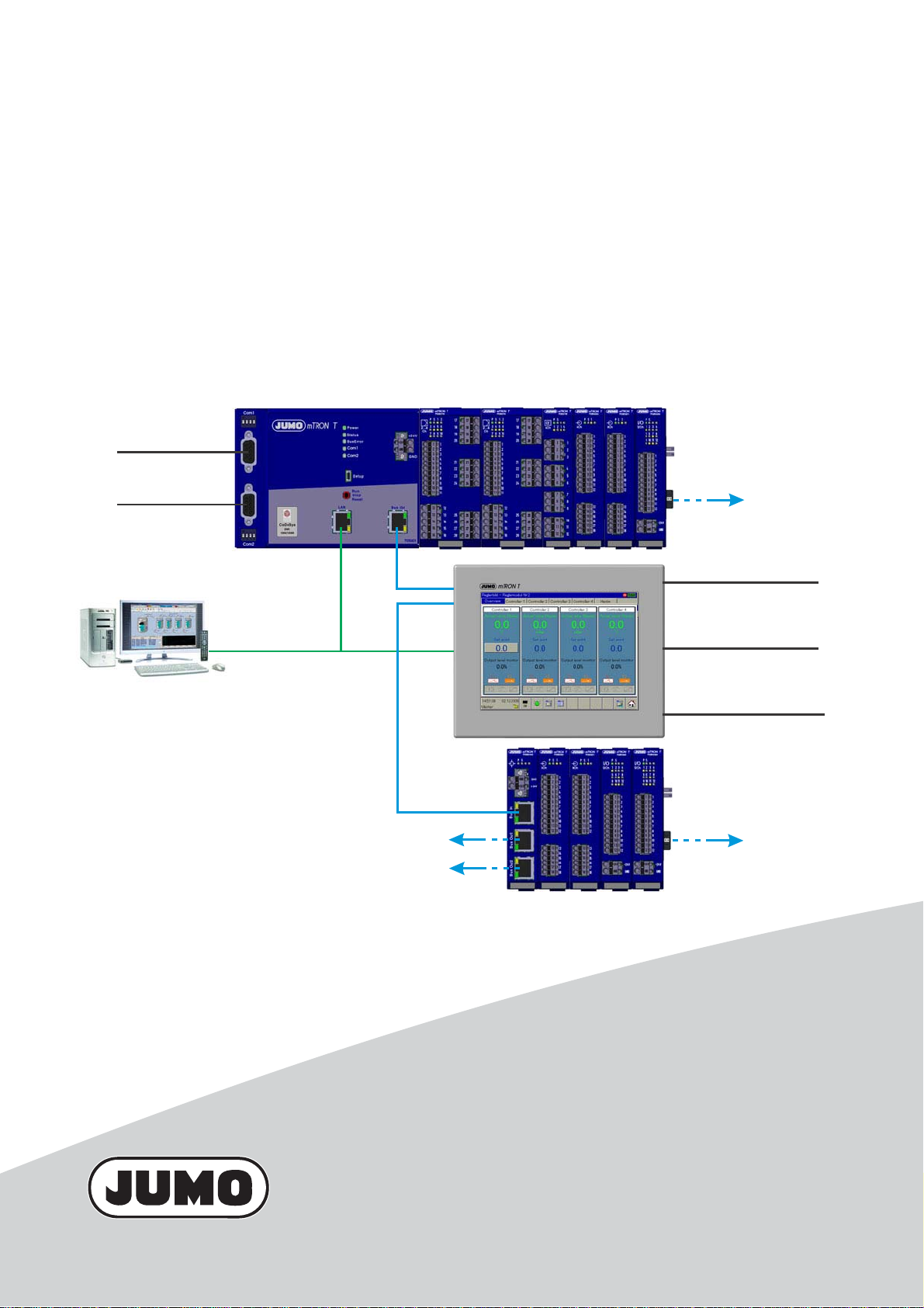
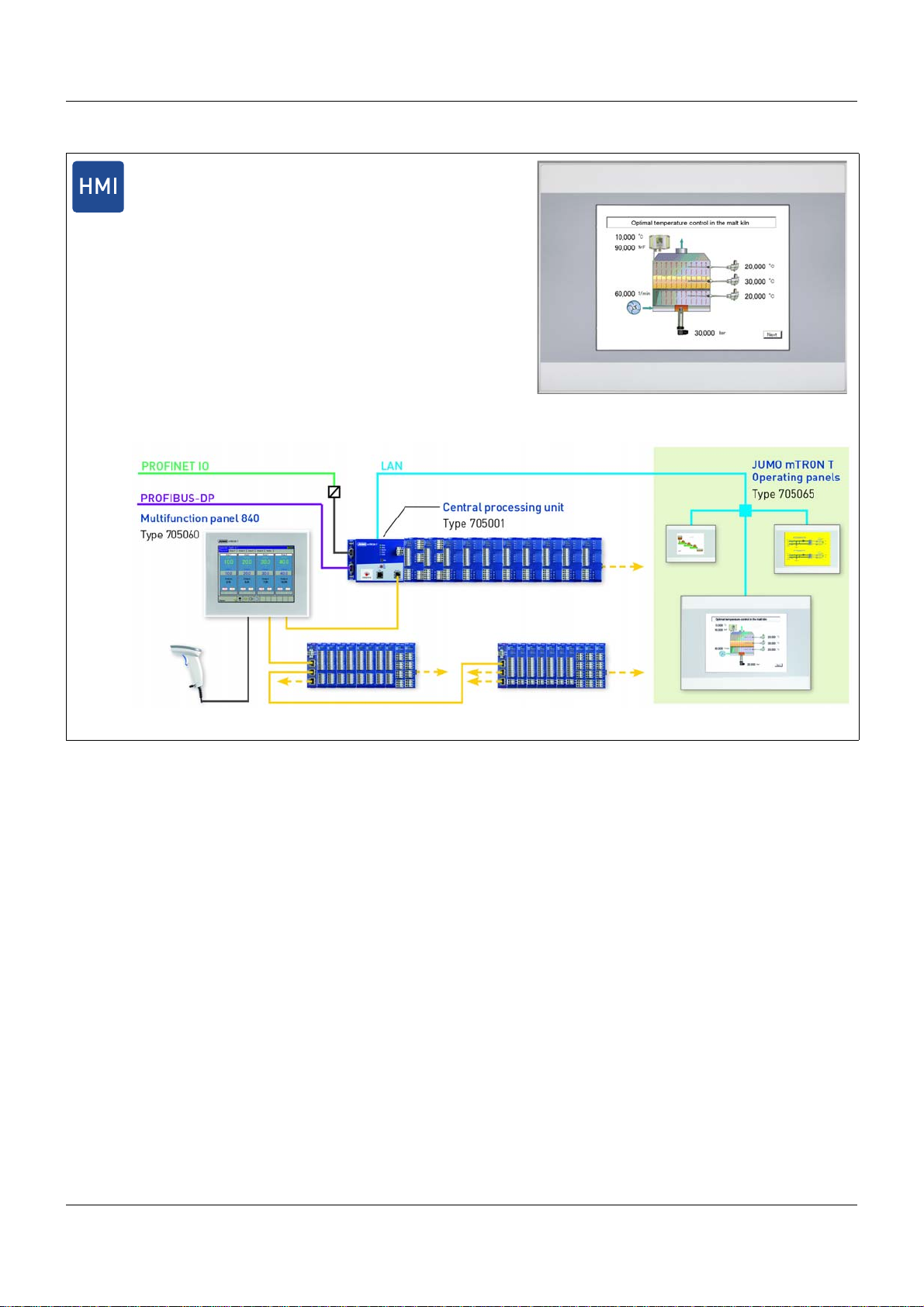
JUMO mTRON T
- Web browser
- Setup program
- PC Evaluation Software PCA3000
- PCA Communication Software PCC
- Plant Visualization Software SVS3000
- Programming system CODESYS
LAN
Com2
RS422/485 or RS232,
Modbus master/slave
or
PROFIBUS-DP slave
System bus
Com1
RS422/485 or RS232,
Modbus master/slave
Com1
Com2
USB
RS422/485 or RS232,
Modbus master/slave,
connection for bar code scanner
RS422/485 or RS232,
Modbus master/slave,
connection for bar code scanner
Host and device
max. 100 m
max. 100 m
Measuring, Control, and Automation System
System Description
B 705000.8
2014-05-06/00575652
Page 2

Page 3

Contents
1 Introduction . . . . . . . . . . . . . . . . . . . . . . . . . . . . . . . . . . . . . . . . . . . . . . . . . . . . . .7
1.1 Structure of this system description . . . . . . . . . . . . . . . . . . . . . . . . . . . . . . . . . . . . . . . . . . . . . . . 7
1.2 The JUMO mTRON T measuring, control, and automation system . . . . . . . . . . . . . . . . . . . . . . . 8
1.2.1 Overview . . . . . . . . . . . . . . . . . . . . . . . . . . . . . . . . . . . . . . . . . . . . . . . . . . . . . . . . . . . . . . . . . . . . 8
1.2.2 Brief description . . . . . . . . . . . . . . . . . . . . . . . . . . . . . . . . . . . . . . . . . . . . . . . . . . . . . . . . . . . . . . . 8
1.2.3 Base units . . . . . . . . . . . . . . . . . . . . . . . . . . . . . . . . . . . . . . . . . . . . . . . . . . . . . . . . . . . . . . . . . . . 9
1.2.4 Input/output modules . . . . . . . . . . . . . . . . . . . . . . . . . . . . . . . . . . . . . . . . . . . . . . . . . . . . . . . . . . 10
1.2.5 Special modules . . . . . . . . . . . . . . . . . . . . . . . . . . . . . . . . . . . . . . . . . . . . . . . . . . . . . . . . . . . . . 12
1.2.6 Operating, visualization, recording . . . . . . . . . . . . . . . . . . . . . . . . . . . . . . . . . . . . . . . . . . . . . . . 13
1.2.7 Power supply units . . . . . . . . . . . . . . . . . . . . . . . . . . . . . . . . . . . . . . . . . . . . . . . . . . . . . . . . . . . 15
1.2.8 PC programs . . . . . . . . . . . . . . . . . . . . . . . . . . . . . . . . . . . . . . . . . . . . . . . . . . . . . . . . . . . . . . . . 16
1.3 Content of the technical documentation . . . . . . . . . . . . . . . . . . . . . . . . . . . . . . . . . . . . . . . . . . . 18
1.3.1 Device documentation in printed form . . . . . . . . . . . . . . . . . . . . . . . . . . . . . . . . . . . . . . . . . . . . . 18
1.3.2 Device documentation in the form of PDF files . . . . . . . . . . . . . . . . . . . . . . . . . . . . . . . . . . . . . . 18
1.3.3 Documentation for optional software . . . . . . . . . . . . . . . . . . . . . . . . . . . . . . . . . . . . . . . . . . . . . . 19
1.3.4 Device documentation on the Internet . . . . . . . . . . . . . . . . . . . . . . . . . . . . . . . . . . . . . . . . . . . . . 20
1.3.5 Training documents on the Internet . . . . . . . . . . . . . . . . . . . . . . . . . . . . . . . . . . . . . . . . . . . . . . . 20
1.4 Available technical documentation . . . . . . . . . . . . . . . . . . . . . . . . . . . . . . . . . . . . . . . . . . . . . . . 21
1.4.1 General information . . . . . . . . . . . . . . . . . . . . . . . . . . . . . . . . . . . . . . . . . . . . . . . . . . . . . . . . . . . 21
1.4.2 Base units . . . . . . . . . . . . . . . . . . . . . . . . . . . . . . . . . . . . . . . . . . . . . . . . . . . . . . . . . . . . . . . . . . 21
1.4.3 Input/output modules . . . . . . . . . . . . . . . . . . . . . . . . . . . . . . . . . . . . . . . . . . . . . . . . . . . . . . . . . . 21
1.4.4 Special modules . . . . . . . . . . . . . . . . . . . . . . . . . . . . . . . . . . . . . . . . . . . . . . . . . . . . . . . . . . . . . 22
1.4.5 Operating, visualization, recording . . . . . . . . . . . . . . . . . . . . . . . . . . . . . . . . . . . . . . . . . . . . . . . 22
1.4.6 Power supply units . . . . . . . . . . . . . . . . . . . . . . . . . . . . . . . . . . . . . . . . . . . . . . . . . . . . . . . . . . . 22
2 Safety information . . . . . . . . . . . . . . . . . . . . . . . . . . . . . . . . . . . . . . . . . . . . . . . .23
2.1 Warning symbols . . . . . . . . . . . . . . . . . . . . . . . . . . . . . . . . . . . . . . . . . . . . . . . . . . . . . . . . . . . . . 23
2.2 Note signs . . . . . . . . . . . . . . . . . . . . . . . . . . . . . . . . . . . . . . . . . . . . . . . . . . . . . . . . . . . . . . . . . . 23
2.3 Intended use . . . . . . . . . . . . . . . . . . . . . . . . . . . . . . . . . . . . . . . . . . . . . . . . . . . . . . . . . . . . . . . . 24
2.4 Qualification of personnel . . . . . . . . . . . . . . . . . . . . . . . . . . . . . . . . . . . . . . . . . . . . . . . . . . . . . . 24
3 Acceptance of goods, storage, and transport . . . . . . . . . . . . . . . . . . . . . . . . .25
3.1 Checking the delivery . . . . . . . . . . . . . . . . . . . . . . . . . . . . . . . . . . . . . . . . . . . . . . . . . . . . . . . . . 25
3.2 Notes on storage and transport . . . . . . . . . . . . . . . . . . . . . . . . . . . . . . . . . . . . . . . . . . . . . . . . . . 25
3.3 Returning goods . . . . . . . . . . . . . . . . . . . . . . . . . . . . . . . . . . . . . . . . . . . . . . . . . . . . . . . . . . . . . 25
3.3.1 Accompanying letter for repair . . . . . . . . . . . . . . . . . . . . . . . . . . . . . . . . . . . . . . . . . . . . . . . . . . 25
3.3.2 Protection against electrostatic discharge (ESD) . . . . . . . . . . . . . . . . . . . . . . . . . . . . . . . . . . . . 25
3.4 Disposal . . . . . . . . . . . . . . . . . . . . . . . . . . . . . . . . . . . . . . . . . . . . . . . . . . . . . . . . . . . . . . . . . . . . 26
4 Identifying the device version . . . . . . . . . . . . . . . . . . . . . . . . . . . . . . . . . . . . . .27
4.1 Nameplates . . . . . . . . . . . . . . . . . . . . . . . . . . . . . . . . . . . . . . . . . . . . . . . . . . . . . . . . . . . . . . . . . 27
4.2 Scope of delivery . . . . . . . . . . . . . . . . . . . . . . . . . . . . . . . . . . . . . . . . . . . . . . . . . . . . . . . . . . . . . 29
4.3 Accessories . . . . . . . . . . . . . . . . . . . . . . . . . . . . . . . . . . . . . . . . . . . . . . . . . . . . . . . . . . . . . . . . . 29
3
Page 4

Contents
4.3.1 General accessories . . . . . . . . . . . . . . . . . . . . . . . . . . . . . . . . . . . . . . . . . . . . . . . . . . . . . . . . . . 29
4.3.2 Central processing unit . . . . . . . . . . . . . . . . . . . . . . . . . . . . . . . . . . . . . . . . . . . . . . . . . . . . . . . . 29
4.3.3 Controller module . . . . . . . . . . . . . . . . . . . . . . . . . . . . . . . . . . . . . . . . . . . . . . . . . . . . . . . . . . . . 30
5 Installation . . . . . . . . . . . . . . . . . . . . . . . . . . . . . . . . . . . . . . . . . . . . . . . . . . . . . .31
5.1 General information on installation/dismounting . . . . . . . . . . . . . . . . . . . . . . . . . . . . . . . . . . . . . 31
5.2 Module sequence . . . . . . . . . . . . . . . . . . . . . . . . . . . . . . . . . . . . . . . . . . . . . . . . . . . . . . . . . . . . 32
5.2.1 System with centralized module assignment . . . . . . . . . . . . . . . . . . . . . . . . . . . . . . . . . . . . . . . 32
5.2.2 System with decentralized module assignment . . . . . . . . . . . . . . . . . . . . . . . . . . . . . . . . . . . . . 33
5.3 Installation/dismounting on DIN rail . . . . . . . . . . . . . . . . . . . . . . . . . . . . . . . . . . . . . . . . . . . . . . . 34
5.3.1 Base units . . . . . . . . . . . . . . . . . . . . . . . . . . . . . . . . . . . . . . . . . . . . . . . . . . . . . . . . . . . . . . . . . . 35
5.3.2 Input/output modules . . . . . . . . . . . . . . . . . . . . . . . . . . . . . . . . . . . . . . . . . . . . . . . . . . . . . . . . . . 38
5.3.3 Special modules . . . . . . . . . . . . . . . . . . . . . . . . . . . . . . . . . . . . . . . . . . . . . . . . . . . . . . . . . . . . . 42
5.4 Mounting in a panel . . . . . . . . . . . . . . . . . . . . . . . . . . . . . . . . . . . . . . . . . . . . . . . . . . . . . . . . . . . 45
5.4.1 Multifunction panel . . . . . . . . . . . . . . . . . . . . . . . . . . . . . . . . . . . . . . . . . . . . . . . . . . . . . . . . . . . 45
5.5 Replacing module inserts . . . . . . . . . . . . . . . . . . . . . . . . . . . . . . . . . . . . . . . . . . . . . . . . . . . . . . 46
5.5.1 Input/output modules . . . . . . . . . . . . . . . . . . . . . . . . . . . . . . . . . . . . . . . . . . . . . . . . . . . . . . . . . . 46
5.5.2 Special modules . . . . . . . . . . . . . . . . . . . . . . . . . . . . . . . . . . . . . . . . . . . . . . . . . . . . . . . . . . . . . 48
6 Electrical connection . . . . . . . . . . . . . . . . . . . . . . . . . . . . . . . . . . . . . . . . . . . . .51
6.1 Installation notes . . . . . . . . . . . . . . . . . . . . . . . . . . . . . . . . . . . . . . . . . . . . . . . . . . . . . . . . . . . . . 51
6.2 Electrical isolation . . . . . . . . . . . . . . . . . . . . . . . . . . . . . . . . . . . . . . . . . . . . . . . . . . . . . . . . . . . . 53
6.3 Voltage supply . . . . . . . . . . . . . . . . . . . . . . . . . . . . . . . . . . . . . . . . . . . . . . . . . . . . . . . . . . . . . . . 55
6.4 Current load . . . . . . . . . . . . . . . . . . . . . . . . . . . . . . . . . . . . . . . . . . . . . . . . . . . . . . . . . . . . . . . . . 57
6.5 System bus . . . . . . . . . . . . . . . . . . . . . . . . . . . . . . . . . . . . . . . . . . . . . . . . . . . . . . . . . . . . . . . . . 59
7 Startup and configuration . . . . . . . . . . . . . . . . . . . . . . . . . . . . . . . . . . . . . . . . .63
7.1 Setup program . . . . . . . . . . . . . . . . . . . . . . . . . . . . . . . . . . . . . . . . . . . . . . . . . . . . . . . . . . . . . . . 64
7.2 Multifunction panel 840 . . . . . . . . . . . . . . . . . . . . . . . . . . . . . . . . . . . . . . . . . . . . . . . . . . . . . . . . 65
8 Appendix . . . . . . . . . . . . . . . . . . . . . . . . . . . . . . . . . . . . . . . . . . . . . . . . . . . . . . .67
8.1 General technical data . . . . . . . . . . . . . . . . . . . . . . . . . . . . . . . . . . . . . . . . . . . . . . . . . . . . . . . . 67
8.1.1 Directives . . . . . . . . . . . . . . . . . . . . . . . . . . . . . . . . . . . . . . . . . . . . . . . . . . . . . . . . . . . . . . . . . . . 67
8.1.2 Electrical safety . . . . . . . . . . . . . . . . . . . . . . . . . . . . . . . . . . . . . . . . . . . . . . . . . . . . . . . . . . . . . . 67
8.1.3 Protection type according to DIN EN 60529 . . . . . . . . . . . . . . . . . . . . . . . . . . . . . . . . . . . . . . . . 67
8.1.4 Protection rating . . . . . . . . . . . . . . . . . . . . . . . . . . . . . . . . . . . . . . . . . . . . . . . . . . . . . . . . . . . . . 67
8.1.5 EMC . . . . . . . . . . . . . . . . . . . . . . . . . . . . . . . . . . . . . . . . . . . . . . . . . . . . . . . . . . . . . . . . . . . . . . 67
8.1.6 Voltage supply . . . . . . . . . . . . . . . . . . . . . . . . . . . . . . . . . . . . . . . . . . . . . . . . . . . . . . . . . . . . . . . 67
8.1.7 Ambient requirements . . . . . . . . . . . . . . . . . . . . . . . . . . . . . . . . . . . . . . . . . . . . . . . . . . . . . . . . . 68
8.1.8 Conformity . . . . . . . . . . . . . . . . . . . . . . . . . . . . . . . . . . . . . . . . . . . . . . . . . . . . . . . . . . . . . . . . . . 68
8.1.9 Climatic tests . . . . . . . . . . . . . . . . . . . . . . . . . . . . . . . . . . . . . . . . . . . . . . . . . . . . . . . . . . . . . . . . 68
8.1.10 Mechanical tests . . . . . . . . . . . . . . . . . . . . . . . . . . . . . . . . . . . . . . . . . . . . . . . . . . . . . . . . . . . . . 69
4
Page 5

Contents
8.2 System expansion (system version 02) . . . . . . . . . . . . . . . . . . . . . . . . . . . . . . . . . . . . . . . . . . . . 71
8.3 Training courses/seminars . . . . . . . . . . . . . . . . . . . . . . . . . . . . . . . . . . . . . . . . . . . . . . . . . . . . . 72
5
Page 6

Contents
6
Page 7
1.1 Structure of this system description
This system description, which is also a component of the system manual (accessories), describes features that relate to the overall measuring, control, and automation system or are
equally applicable for all modules.
The complete scope of information for each module is contained in the downloadable operating
manuals.
NOTE!
The user should follow the individual sections of this system description step for step to gain
an overview of the measuring, control, and automation system and the available technical
documentation.
Content of the individual sections
Section Explanation
1 Introduction • Initial information on the measuring, control, and automation sys-
tem
• Find out how the technical documentation is structured
1 Introduction
2 Safety information • Symbols and types of figures used and their meanings
3 Receipt of goods, storage,
and transport
4 Identifying the
device version
5 Installation • Correctly fitting or installing the devices, taking into conside ratio n
6 Electrical connection • Safely connecting the devices, taking into consideration the "in-
7 Startup and
configuration
• Checking the delivery for damage and completeness
• Notes on storage and transport
• Handling the packaging material
• Notes on disposal
• Detecting which device version is indicated by the specifications
on the nameplate
the prevailing climatic conditions at the installation location
stallation notes"
• Starting up and configuring the system using the setup program
(overview).
• Configuring and operating the system using the multi function p anel (overview).
NOTE!
All additional information is module-specific and is contained in the respective index divider
of the system manual and in the downloadable operating manuals.
7
Page 8
1 Introduction
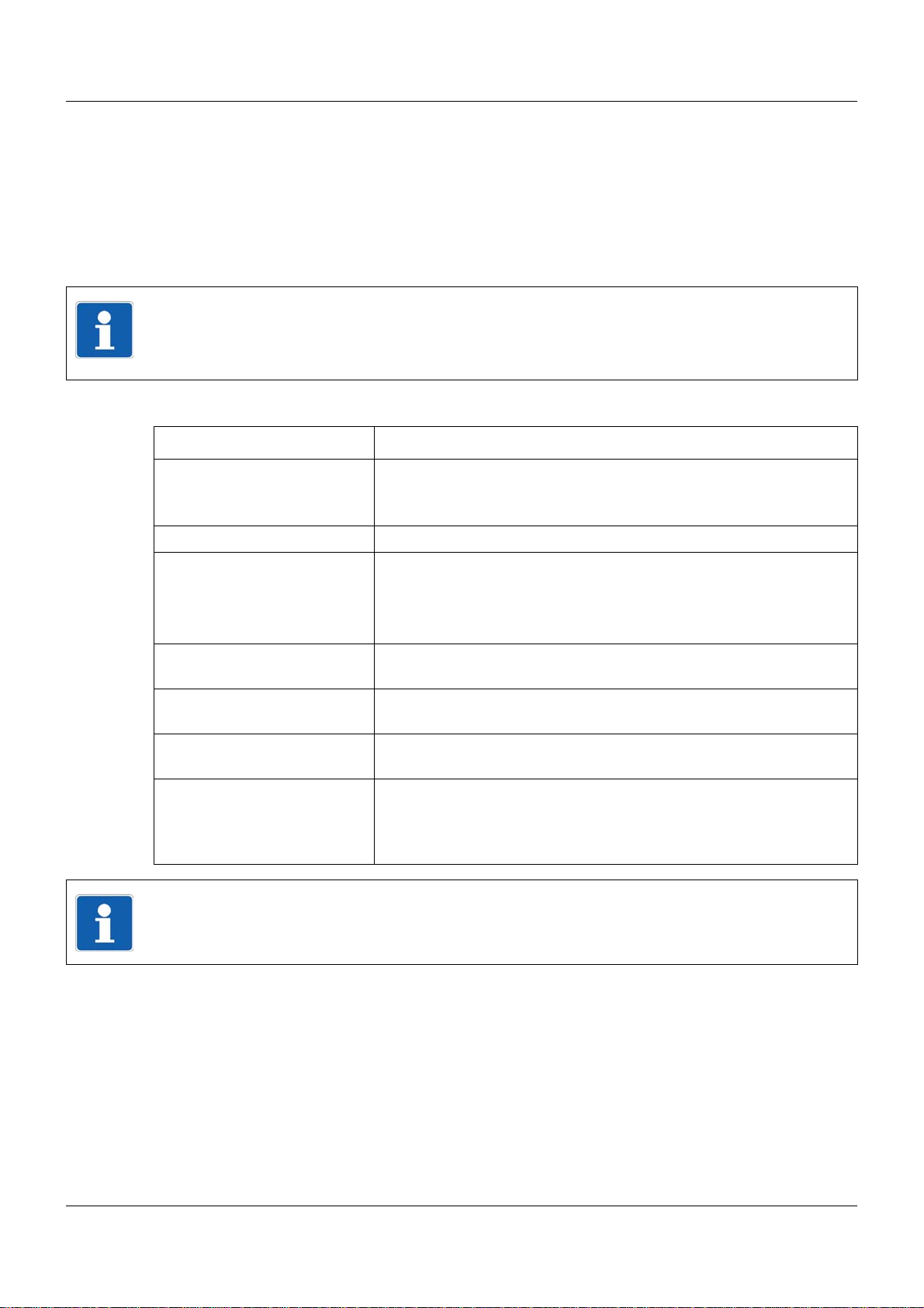
- Web browser
- Setup program
- PC Evaluation Software PCA3000
- PCA Communication Software PCC
- Plant Visualization Software SVS3000
- Programming system CODESYS
LAN
Com2
RS422/485 or RS232,
Modbus master/slave
or
PROFIBUS-DP slave
System bus
Com1
RS422/485 or RS232,
Modbus master/slave
Com1
Com2
USB
RS422/485 or RS232,
Modbus master/slave,
connection for bar code scanner
RS422/485 or RS232,
Modbus master/slave,
connection for bar code scanner
Host and device
max. 100 m
max. 100 m
1.2 The JUMO mTRON T measuring, control, and automation system
1.2.1 Overview
1.2.2 Brief description
The modular measuring, control, and automation system is suitable for the precise detection,
regulation, control, and recording. Special features of the system are the easy operation and
the corresponding software components, the high measuring accuracy and regulation quality
8
as well as the sturdy and service-friendly mechanical system.
An application consists of a base unit (central processing unit), a maximum of 30 input/output
modules (multichannel controller module, analog input module 4-channel, analog input mod ule
8-channel, digital input/output module 12-channel), and if necessary the multifunction p anel, up
to four operating panels, and router modules for distributed module arrangement. For userfriendly all-in-one solutions, various PC programs are available.
Automation solutions for small and medium size machine lines are possible due to the integration of an optional PLC including programming system according to IEC 61131-3.
The base unit is equipped with a sturdy metal case; the router module and the input and output
modules are equipped with a plastic case. All these devices can be fitted on a 35 mm DIN rail.
The multifunction panel with TFT touch screen has a metal case with decor foil and is intended
for mounting into a panel cut-out.
The system operates at a voltage of DC 24 V. The supply of operating voltage is only requ ired
at the base unit (central processing unit), at the router module, and at the multifunction panel.
Page 9
1.2.3 Base units
• The base unit, up to 30 input/output modules, and up to 30 router modules can be used to
build a compact and economic central or decentral measuring, control, and automation system (visualization and operation either with the multifunction panel or the plant visualization
software JUMO SVS3000).
• The base unit s cont ain the process image of the application. Furthermore, all configuration
and parameter data of the system are stored in these modules (except for the multifunction
panel). As a result, individual input/output modules can be replaced with Plug and Play.
• All base units operate at a voltage supply of DC 24 V.
• The setup program or the multifunction panel ca n be used to comfortab ly configure and pa-
rameterize the base units.
• LEDs are used to indicate the voltage supply as well as the operating status of a module
and of the interfaces.
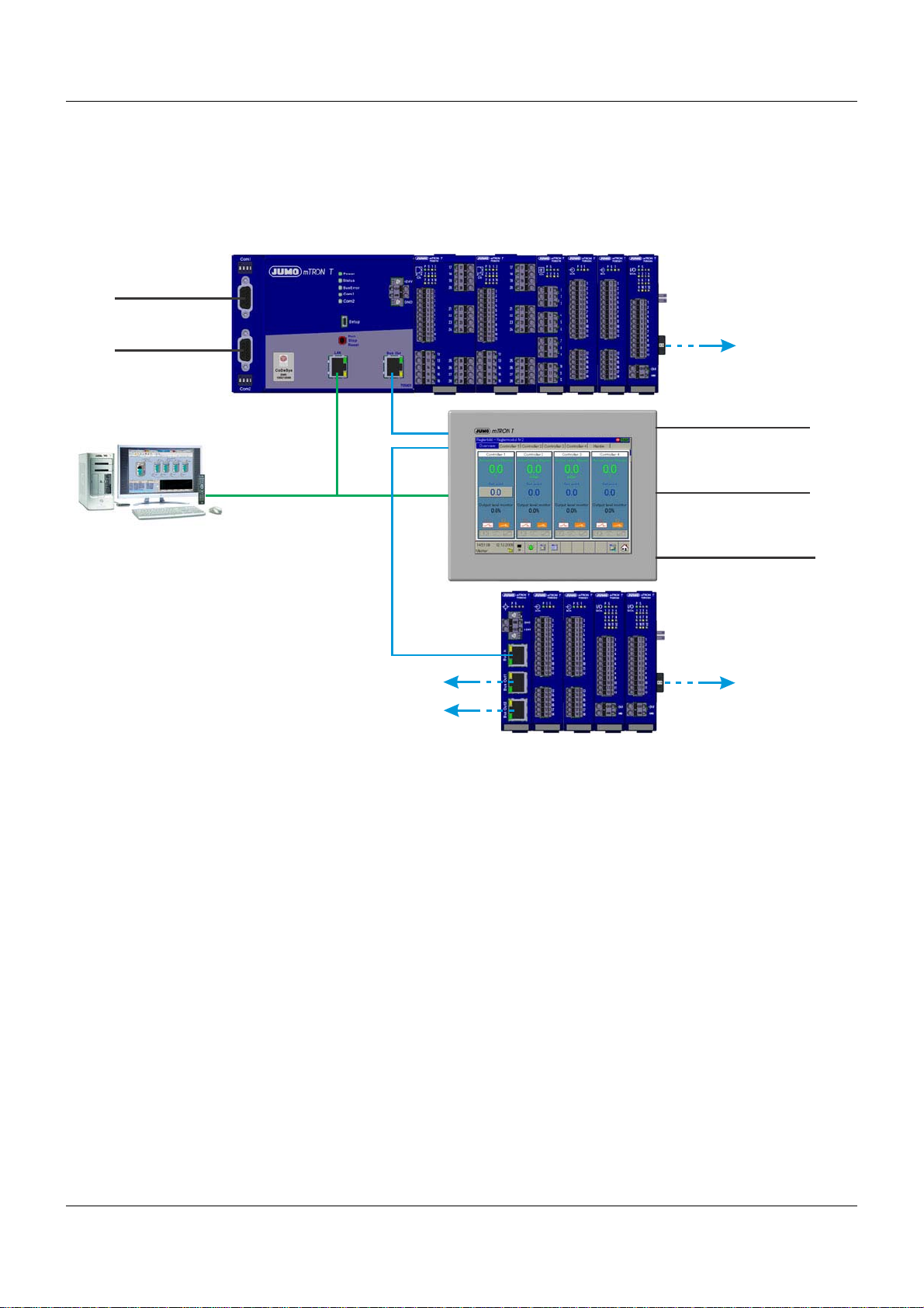
Central processing unit
• The central processing unit is the basis for the maximum extension of the system
• Nine program generators (option)
• 64 limit values are monitored
• An integrated PLC acc. to IEC 61131-3 (option)
• Math and logic function (option) for all connected multichannel
controller modules
• Two interfaces for field bus applications; optional:
- RS232, Modbus RTU as master or slave
- RS422/485 Modbus RTU as master or slave
- PROFIBUS-DP as slave (as of system version 02)
• One USB device interface (setup)
• System bus connection at the front (Bus Out)
• A LAN interface (Ethernet) for HTTP and Modbus/TCP as
master and slave
• Integrated web server
• E-mail transmission
• The central processing unit operates at a voltage supply of
DC 24 V and supplies the connected input/output modules
• Dimensions (W x H x D): 135 mm x 101 mm x 67.1 mm
(without connection elements)
For further information: Refer to data sheet 705001
1 Introduction
Additional base units in preparation.
9
Page 10
1 Introduction
1.2.4 Input/output modules
• The modules are equipped with removable terminal strips with Push-In technology for the
electrical connection.
• All input/output modules operate at a voltage supply of DC 24 V.
• The setup program, the multifunction p anel or the optional PLC can be used to comfort ably
configure and parameterize the modules.
• LEDs are used to indicate the voltage supply as well as the operating status of a module
and the input/output statuses.
• For service work (replacemen t) or adding option al boards, the module insert can be easily
pulled out of the case at the front.
Multichannel controller module
• 2-channel PID controller with relay output or logic output
to control solid-state relays
• Up to 4 PID controller channels can be activated (cascadable)
• Two universal analog inputs, two digital inputs
(DC 0/24 V) and two digital outputs (relay or logic DC 0/15 V)
• Supported measuring probes: Thermocouples, RTD temperature probes, resistance transmitters, resistance/potentiometers, or standard signals (current or voltage)
• The analog inputs are electrically isolated from each other
• Three option slots for the extension of up to four
universal analog inputs, eight digital inputs,
three analog outputs, or eight digital outputs
• Su pported controller types: Two-state controller, three-state
controller, modulating controller, continuous controller, or continuous controller with integrated actuator controller
• Customer-specific linearization possible by using a formula
• Limit value monitoring
• Four formulae for math and logic functions (option)
• One counting input up to 10 kHz
• The module operates independently (configurable) which
means the control task is carried out even if the base unit or
the higher-ranking system malfunctions
• If the controller is replaced during service work the new controller (identical type) is automatically configured
• Dimensions (W x H x D): 45 mm x 103.6 mm x 101.5 mm
(without connection elements)
For further information: Refer to data sheet 705010
10
Page 11
Relay module 4-channel
• Four relay outputs controlled via the system bus by digital signals
• Each relay is equipped with a changeover contact
AC 230 V / 3 A
• Separate terminal strip per relay output
• Automatic configuration after the module insert has been exchanged during service work
• Dimensions (W x H x D): 22.5 mm x 103.6 mm x 101.5 mm
(without connection elements)
For further information: Refer to data sheet 705015
Analog input module 4-channel
• Four universal analog inputs
• Supported measuring probes: Thermocouples, RTD temperature probes, resistance transmitters, resistance/potentiometers or standard signals (current or voltage)
• The analog inputs are electrically isolated from each other
• Customer-specific linearization possible by using a formula or
up to 45 pairs of values
• Limit value monitoring
• Automatic configuration after the module insert has been exchanged during service work
• A digital input (DC 0/24 V) is also provided
• Dimensions (W x H x D): 22.5 mm x 103.6 mm x 101.5 mm
(without connection elements)
1 Introduction
For further information: Refer to data sheet 705020
Analog input module 8-channel
• Eight analog inputs for RTD temperature probes Pt100, Pt500
or Pt1000 in 2-wire circuit
• The analog inputs are not electrically isolated from each other
• Limit value monitoring
• Automatic configuration after the module insert has been exchanged during service work
• A digital input (DC 0/24 V) is also provided
• Dimensions (W x H x D): 22.5 mm x 103.6 mm x 101.5 mm
(without connection elements)
For further information: Refer to data sheet 705021
11
Page 12
1 Introduction
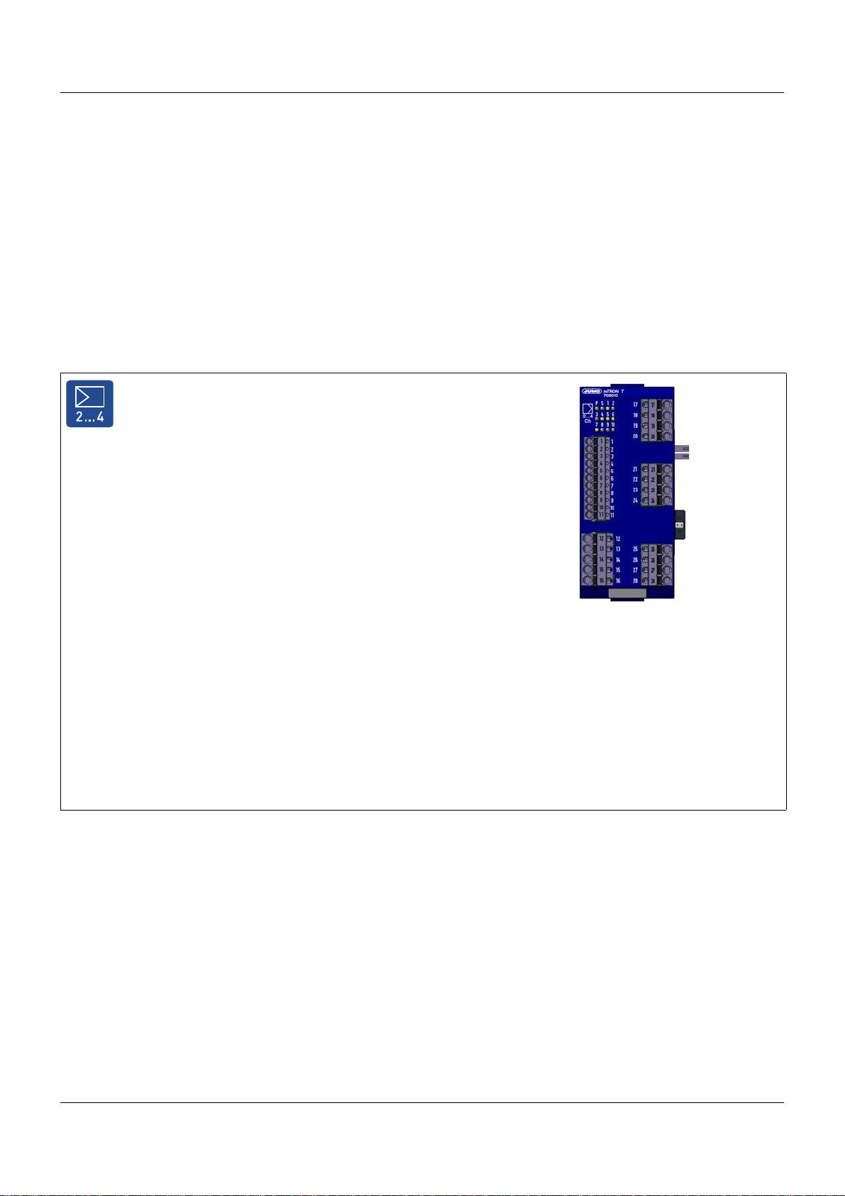
Digital input/output module 12-channel
• 12 channels which can be respectively configured as digital inputs (DC 0/24 V) or as digital outputs (DC 0/24 V, 500 mA)
• Supply of external voltage through terminal at the front
• Automatic configuration after the module insert has been exchanged during service work
• Dimensions (W x H x D): 22.5 mm x 103.6 mm x 101.5 mm
(without connection elements)
For further information: Refer to data sheet 705030
1.2.5 Special modules
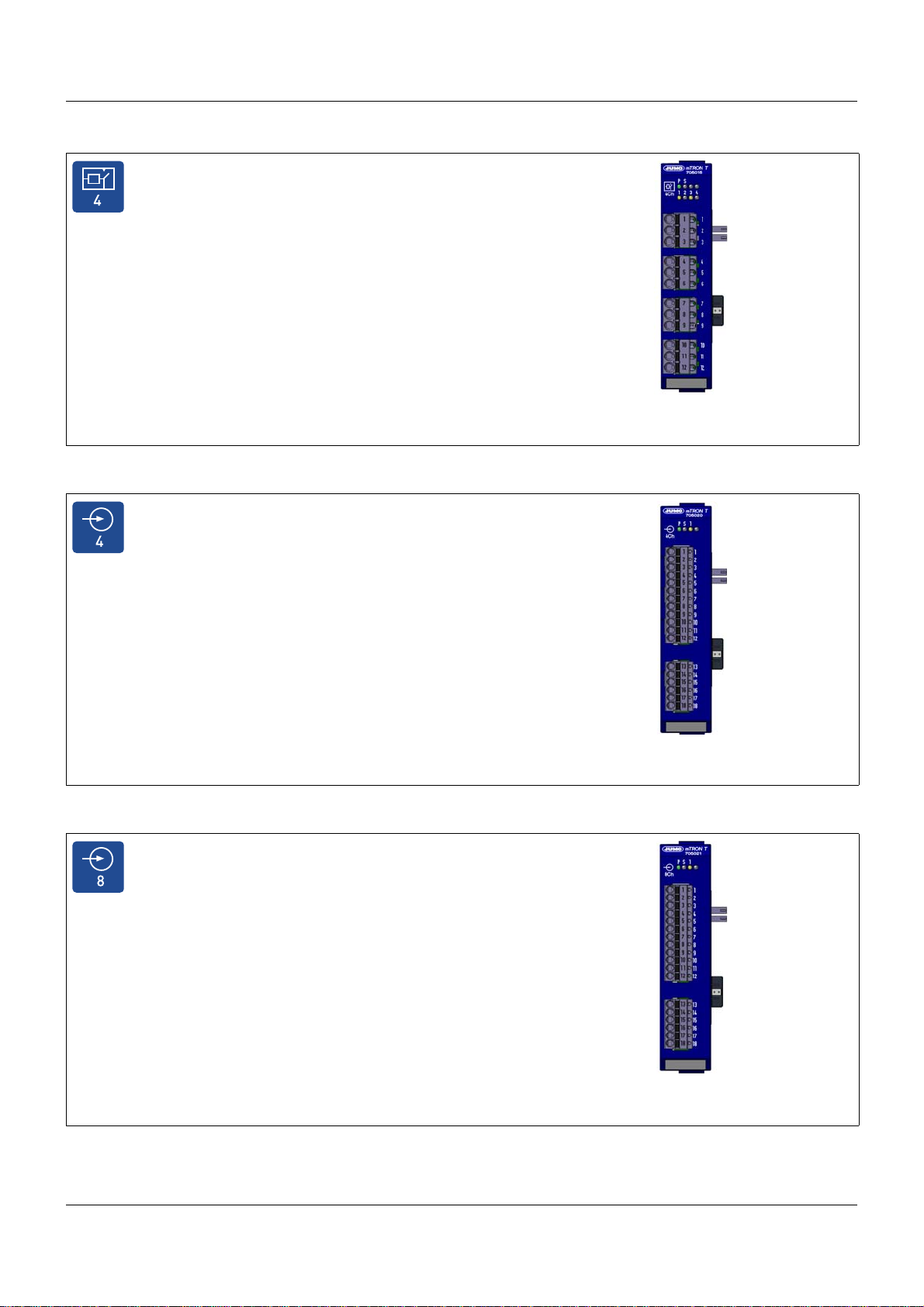
Router module
• The router module distributes the input/output modules to
several DIN rails/control cabinets (decentralized arrangement)
• It uses the system bus to link modules to the base unit or the
multifunction panel
• Up to 100 m distance between two router modules or between
a router module and the base unit or the multifunction panel
• Up to 30 router modules are possible
• The router module operates at a voltage supply of DC 24 V and
supplies the connected input/output modules
• No configuration of the router module required
• For applications such as Hot Connect, for example, the address of the router module can be set by rotary coding switches
• Three RJ45 system bus connections at the front
(1 × Bus In, 2 × Bus Out), electrically isolated
• Dimensions (W x H x D): 22.5 mm x 103.6 mm x 101.5 mm
(without connection elements)
For further information: Refer to data sheet 705040
12
Page 13
1.2.6 Operating, visualization, recording
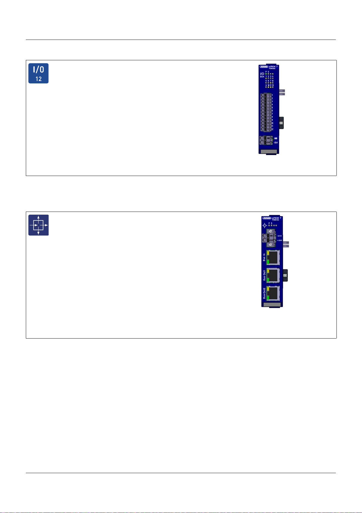
Multifunction panel 840
• Touchscreen with front made of aluminum incl. design foil
(IP67)
• TFT color monitor 21.3 cm (8.4”),
resolution 640 x 480 pixels, 256 colors, with LED backlight
• As an interface between man and machine it allows an optimal
and clearly-arranged view of the process statuses and parameters of the system
• Display (in real time) and operation of controller screen, process screen, program editor, and recording function (option)
• Configuration of all connected modules
• Setpoint values and batch texts are directly entered on the
screen
• Data archiving and evaluation with PC
• The multifunction panel operates at a voltage supply of
DC 24 V
• A setup program can be used to comfortably configure the
multifunction panel
• Two interfaces for field bus applications; optional:
- RS232, Modbus RTU as master or slave
- RS422/485, Modbus RTU as master or slave
• One USB device interface (setup)
• Two USB host interfaces (memory stick)
• Two system bus connections (Bus In and Bus Out)
• A LAN interface (Ethernet) for HTTP and Modbus/TCP as
master and slave
• Integrated web server
• E-mail transmission
• Connection possibility for barcode scanner
• Dimensions (W x H x D): 235mm x 195mm x 58mm
For further information: Refer to data sheet 705060
1 Introduction
13
Page 14
1 Introduction
Operating panels 350, 570, 1040
• TFT color display (64k colors) with resistiv-touch technology
• Display sizes 8.9 cm (3.5''), 14.5 cm (5.7''), and 26.4 cm
(10.4'')
• Display resolutions 320 × 240 pixels and 640 × 480 pixels
• Different case materials (plastics, metal)
• Protection type IP65 (at the front)
• Voltage supply DC 24 V
• Ethernet interface (RJ45) for connection to the system
• Up to four operating panels per central processing unit (PLC
option required)
• Specific process screens for operating the system
• Direct access to PLC variables
System structure:
For further information: Refer to data sheet 705065
14
Page 15
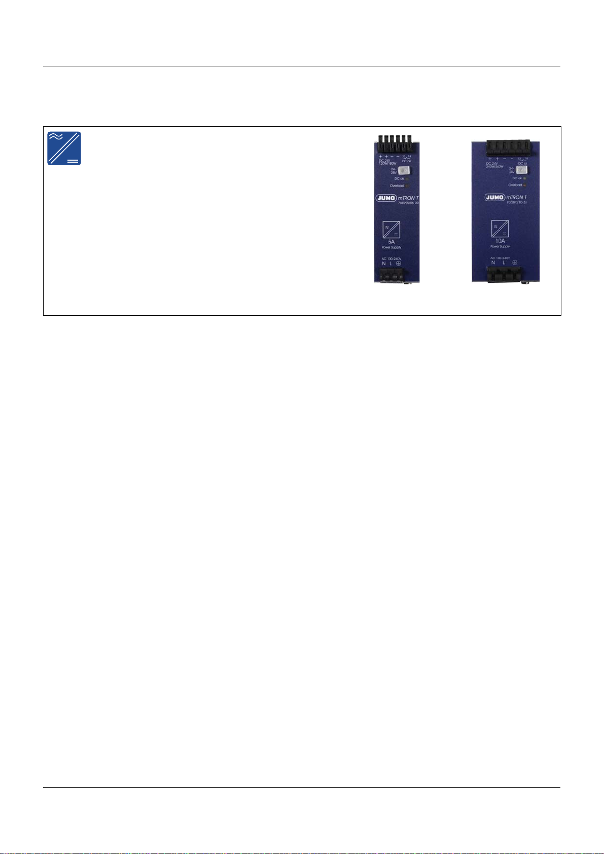
1.2.7 Power supply units
Power supply units 705090/...
• Voltage supply AC 100 V... 240 V
• 150 % peak load capability (for typical 4 s)
• M inimum current inrush
• Floating DC-OK relay contact
• Efficiency up to 93.5 %
• Active power factor correction (PFC)
• Active filter against mains transients
• Quick connection due to spring-cage terminals
• Dimensions (WxHxD):
705090/05-33: 40 mm x 130.5 mm x 121.5 mm
705090/10-33: 60 mm x 130.5 mm x 121.5 mm
For further information: Refer to data sheet 705090
1 Introduction
15
Page 16
1 Introduction
1.2.8 PC programs
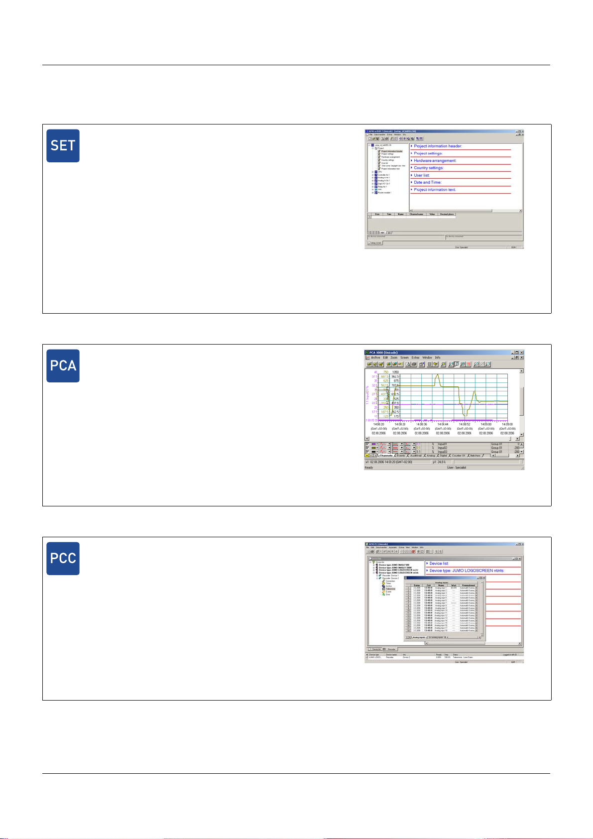
Setup program
Setup program for project planning and configuration of the entire
measuring, control, and automation system
A complete PLC can be activated as an option.
The setup program is distinguished by:
• User-friendly configuration, parameterization, and startup of
the base units, the input/output modules, and the multifunction
panel
• Automatic import of the hardware configuration into the PLC
programming software CODESYS
• Program editor
• Process screen editor
The project file contains all data that is relevant for the configuration, parameterization, and visualization. The file also contains the
controller programs and, if applicable, the customer-specific PLC
code.
For further information: Refer to operating manual 705000.6
PC Evaluation Software PCA3000
Professional evaluation software to manage, archive, visualize and
evaluate process data (measuring data, batch data, messages, ...)
The process data can be imported via USB memory stick or provided by the software PCC.
• Data memory: Clearly arranged and easy backup and archiving of all process data in a data file
• Data backup: Archive data can directly be imported from CD/
DVD and then displayed
• Data export: Data export to HTML level or ASCII text file
(for evaluation in Excel) or customer-specific forms
• Communication: The communication software PCC optimally
adapted to PCA3000 can be used to comfortably import data
via an interface or a modem
For further information: Refer to operating manual 709701.0
PCA Communication Software PCC
The communication software PCC optimally adapted to PCA3000
can be used to comfortably import data via an interface or modem.
• Data memory: Clearly-arranged, easy backup and archiving of
all process data in a data file
• Teleservice function (display of the process data)
For further information: Refer to operating manual 709702.0
16
Page 17
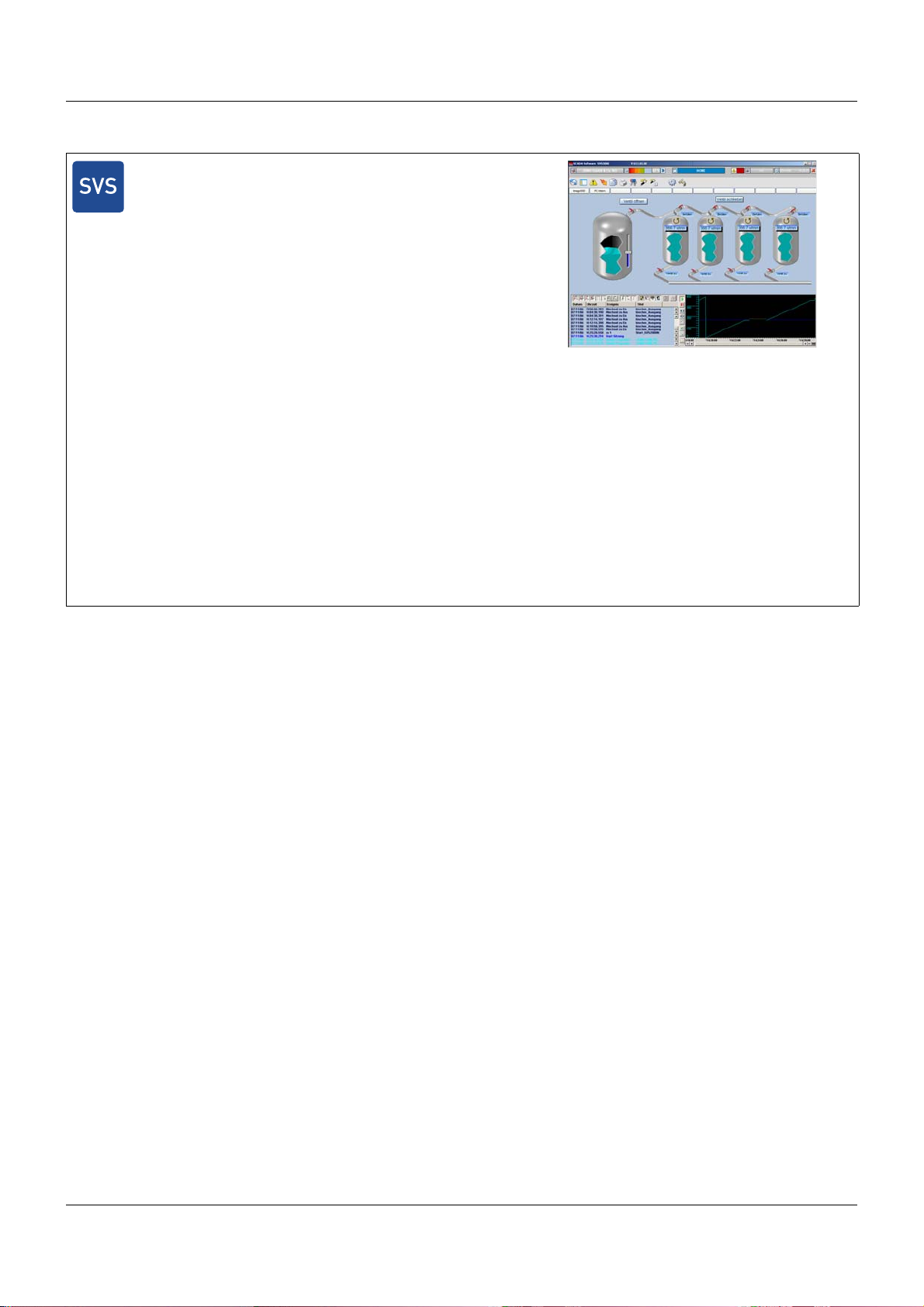
Plant Visualization Software JUMO SVS3000
Plant Visualization Software for online visualization, batch reporting and operation of the measuring, control and automation system
with a networked PC
This software ensures quick familiarity and easy creation of applications. The user is able to quickly configure an individual application according to his/her requirements due to the prepared masks
(process, group, trend screens).
• Easy and quick application creation
• Extensive library with predefined graphical elements
• System operation via group masks
• Extensive do cumentation function with continuous and batch
related evaluation
• Search function for date/time, plant, and batch criteria to be
defined
• Automatic print and data export
• Recipe function
• Quick and easy commissioning/startup due to installation
menu
• Alarm and event list
• Pa ssword protected
• History and real time trend
• Networ k compatible
• Connection of bar code scanner
• Remote alerting (optional)
For further information: Refer to data sheet 700755
1 Introduction
17
Page 18

1 Introduction
1.3 Content of the technical documentation
The documentation for the measuring, control, and automation system is intended for plant
manufacturers and users with specialist training. It has a modular structure and comprises different sections.
1.3.1 Device documentation in printed form
B 7050XX.4
Installation instructions
A hard copy of the installation instructions is included in the scope of delivery of every modu le.
The installation instructions describe the installation of the device and the connection of the
supply and signal cables. They also contain the order details and a list of technical data.
The scope of delivery for a power supply unit includes a hard copy of the operating instructions.
These include information on installation and electrical connection.
B 705000.0
System manual
A hard copy of the system manual can be provided as an accessory subject to charge.
The system manual describes the scope of services of the measuring, control, and automation
system and provides all information for project design and startup.
Index divider 1 "System description" summarizes the information applicable to all modules.
Module-specific descriptions in the following sections complement the specifications stated
here.
Index divider 2 "Setup program" describes the project design of the overall system.
1.3.2 Device documentation in the form of PDF files
The device documentation files specified below are saved as PDF files on the DVD contained
in the scope of delivery of a base unit.
T 705000
Data sheet
The data sheet provides general information on the measuring, control, an d automation system
and forms the basis for plant planning and purchase decisions.
T 7050XX
Data sheet
The data sheets of the individual modules provide spe cific information, order det ails, and technical data.
B 7050XX.0
Operating manual
The operating manuals of the individual modules contain all information on installation, electrical connection, startup, operation, and – if required – parameterization and configuration.
18
Page 19

B 7050XX.2.0
Interface description (Modbus interface)
It provides information on communication with other devices or superordinate systems using
the Modbus protocol (Modbus RTU, Modbus TCP).
B 7050XX.4
Installation instructions
The installation instructions describe the installation of the device and the connection of the
supply and signal cables. The instructions also contain a list of the technical data.
B 7050XX.5.X
Operating manual (application)
The operating manual describes the use of a certain application (e. g. PLC application).
1.3.3 Documentation for optional software
The manuals specified below are available on the Internet as PDF files. They also form part of
the scope of delivery of the respective software.
1 Introduction
B 705000.6
B 709701.0
B 709702.0
B 700755.0
Setup program
The manual describes the function of the setup program.
PC evaluation software PCA3000
The operating manual describes the operation and the features of the PC evaluation sof tware.
The PC evaluation software helps to visualize and evaluate the recorded process data (measurement data, batch data, messages, etc.).
PCA communication software PCC
The operating manual describes the operation and the features of the PCA communication
software. The PCA communication software is responsible for the data transfer from a device
or system to a PC or to a network.
Plant visualization software SVS3000
The operating manual describes the operation and features of the plant visualization software.
The plant visualization software is responsible for networking interface-ready process devices
with a PC.
19
Page 20

1 Introduction
1.3.4 Device documentation on the Internet
All documents are available for download on the Internet at www.jumo.net.
Download procedure:
Step Action
1 On the JUMO website, enter the number of th e relevant pro duct group in the sea rch field at
the top right (e.g. 705001 for the central processing unit) and st art the search.
The search results are listed.
2 Select product (click the link).
3 In the "Documentation" dropdown list, select the desired documentation in the required
national language (click the link).
4 +++++Open the PDF document or save it as a file.
1.3.5 Training documents on the Internet
Training documents (eLearning courses) on various topics are available at www.jumo.net.
Procedure:
Step Action
1 On the JUMO website, navigate to the "Support/Services" area.
2 In the "Information & Training" menu on the left-hand side, select "eLearning courses".
3 Click the link "Review of our eLearning courses".
4 Select the desired eLearning course from the overview (click the link).
The presentation starts.
20
Page 21
1.4 Available technical documentation
The documents specified below are available for the measuring, control, and automation system.
1.4.1 General information
Product Type of documentation No. Printed PDF file
Measuring,
control, and
automation system
1
Accessory subject to charge
2
Includes an overview of the purpose and content of all documents
1.4.2 Base units
Data sheet T 705000 - X
System manual
Setup program manual B 705000.6 - X
System description
1
2
1 Introduction
B 705000.0 X -
B 705000.8 - X
Product Type of documentation No. Printed PDF file
Central
processing unit
Data sheet T 705001 - X
Operating manual B 705001.0 - X
Modbus interface description B 705001.2.0 - X
Installation instructions B 705001.4 X X
1.4.3 Input/output modules
Product Type of documentation No. Printed PDF file
Multichannel
controller module
Relay module
4-channel
Analog
input module
4-channel
Data sheet T 705010 - X
Operating manual B 705010.0 - X
Installation instructions X X
Data sheet T 705015 - X
Operating manual B 705015.0 - X
Installation instructions B 705015.4 X X
Data sheet T 705020 - X
Operating manual B 705020.0 - X
Installation instructions B 705020.4 X X
Analog
input module
8-channel
Digital input/
output module
12-channel
Data sheet T 705021 - X
Operating manual B 705021.0 - X
Installation instructions B 705021.4 X X
Data sheet T 705030 - X
Operating manual B 705030.0 - X
Installation instructions B 705030.4 X X
21
Page 22
1 Introduction
1.4.4 Special modules
Product Type of documentation No. Printed PDF file
Router module Data sheet T 705040 - X
Installation instructions B 705040.4 X X
1.4.5 Operating, visualization, recording
Product Type of documentation No. Printed PDF file
Multifunction
panel 840
Operating panels Data sheet T 705065 - X
Data sheet T 705060 - X
Operating manual B 705060.0 - X
Modbus interface description B 705060.2.0 - X
Installation instructions B 705060.4 X X
1.4.6 Power supply units
Product Type of documentation No. Printed PDF file
24 V power supply
units
Data sheet T 705090 - X
Operating instructions QS5.241 X Operating instructions QS10.241 X -
22
Page 23
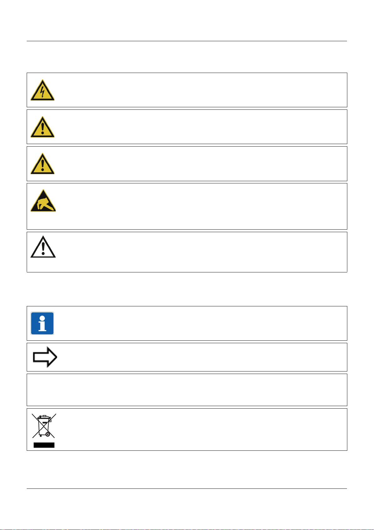
2.1 Warning symbols
&
DANGER!
This symbol indicates that personal injury caused by electrical shock may occur if the respective precautionary measures are not carried out.
WARNING!
This symbol in connection with the signal word indicates that personal injury may occur if the
respective precautionary measures are not carried out.
CAUTION!
This symbol in connection with the signal word indicates that damage to assets or data loss
will occur if the respective precautionary measures are not taken.
CAUTION!
This symbol indicates that components could be destroyed by electrostatic discharge
(ESD = Electro Static Discharge) if the respective cautionary measures are not taken.
Only use the ESD packages intended for this purpose to return device inserts, assembly
groups, or assembly components.
2 Safety information
READ DOCUMENTATION!
This symbol – placed on the device – indicates that the associated device documentation
has to be observed. This is necessary to recognize the kind of the potential hazards as
well as the measures to avoid them.
2.2 Note signs
NOTE!
This symbol refers to important information about the product, its handling, or additional
use.
REFERENCE!
This symbol refers to further information in other sections, chapters, or manuals.
FURTHER INFORMATION!
This symbol is used in the tables and refers to further information in connection with the
table.
DISPOSAL!
This device and the batteries (if installed) must not be disposed in the garbage can after
use! Please ensure that they are disposed properly and in an environmentally friendly
manner.
23
Page 24

2 Safety information
2.3 Intended use
The modules described are intended for measuring, control, an d automation t asks in an ind ustrial environment, as described in the technical data. Oth er uses or uses beyond th ose defined
are not viewed as intended uses.
The modules are built according to the relevant standards and directives as well as the applicable safety regulations. Nevertheless, incorrect use may lead to bodily injury or property damage.
To avoid danger, the modules may only be used:
• For the intended use
• When in good order and condition
• When taking into account the technical documentation provided
Even if a module is used correctly and according to the intended use, it may still cause appli-
cation-related dangers (e.g. due to missing safety devices or incorrect settings).
2.4 Qualification of personnel
This document contains the necessary information for the intended use of the modules to which
it relates.
It is intended for technically qualified personnel who have received special training and have
the appropriate knowledge in the field of automation technology (measuring, process, and control technology).
The appropriate level of knowledge and the technically fault-free implementation of the safety
information and warnings contained in the technical documentation provided are prerequisites
for risk-free mounting, installation, and startup as well as for ensuring safety when operating
the described modules. Only qualified personnel have the required specialist knowledge to correctly interpret and implement the safety information and warnings contained in this document
in specific situations.
24
Page 25

3 Acceptance of goods, storage, and transport
3.1 Checking the delivery
• Ensure that the packaging and contents are not damaged
• Check that the delivery is complete using the delivery papers and the order details
• Inform the supplier immediately if there is any damage
• Store damaged parts until clarification is received from the supplier
3.2 Notes on storage and transport
• Store the module in a dry and clean environment. Observe the admissible ambient conditions (see "Technical data")
• The transport of the module is to be shockproof
• The original packaging provides optimum protection for storage and transport
3.3 Returning goods
In the event of repair, please return the module in a clean and complete state.
Use the original packaging to return goods.
3.3.1 Accompanying letter for repair
Please include the completed accompanying letter for repair when returning goods.
Do not forget to state the following:
• Description of the application and
• Description of the error that has occurred
The accompanying letter for repair can be downloaded online from the manufacturer's website
(use the search function if necessary).
3.3.2 Protection against electrostatic discharge (ESD)
(ESD = electrostatic discharge)
To prevent damage from ESD, electronic modules or components must be handled, packaged,
and stored in an ESD-protected environment. Measures against electrostatic discharge and
electrical fields are described in DIN EN 61340-5-1 and DIN EN 6 1340-5-2 "Protection of electronic devices from electrostatic phenomena".
When returning electronic modules or components, please note the following:
• Sensitive components must only be packaged in an ESD-protected environment. Workspaces such as this divert electrostatic charges to ground in a controlled manner and prevent static charges due to friction capacities.
• Only use packaging for ESD-sensitive modules/components. These must consist of conductive plastics.
No liability can be assumed for damage caused by ESD.
25
Page 26

3 Acceptance of goods, storage, and transport
CAUTION!
Electrostatic charges occur in non-ESD protected environments.
Electrostatic discharges can damage modules or components.
For transport purposes, use only the ESD packaging provided.
3.4 Disposal
Disposing of the device
DISPOSAL!
Devices and/or replaced parts should not be placed in the refuse bin at the end of their service life as they consist of materials that can be recycled by specialist recycling plants.
Dispose of the device and the packaging material in a proper and environmentally friendly
manner.
For this purpose, observe the country-specific laws and regulations for waste treatment a nd
disposal.
Disposing of the packaging material
The entire packaging material (cardboard packaging, inserts, plastic film, and plastic bags) is
fully recyclable.
26
Page 27

4.1 Nameplates
(A) (B)
The position and content of the nameplates is explained below using the example of the multichannel controller module 705010.
Position
The nameplate (B) is affixed to the module case.
Additional nameplates with reduced information are located on the module insert (A) and inside
the module case (C; not shown). This duplicate identification marking via nameplates (A) and
(C) is important when replacing a module insert or retrofitting optional modules.
4 Identifying the device version
Content
The nameplates contain important information. This includes:
Device type
Compare the specifications on the nameplate with the order.
Identify the supplied device version using the order details of the respective module.
Part no. (TN)
The part no. clearly identifies an article in the catalog. It is important for communication
between the customer and the sales department.
Description Designation on the name-
plate
Device type (A + B + C) Typ 705010/18-113-36
Part no. (A + B + C) TN 00XXXXXX
Fabrication number (A + B + C) F-Nr 0070033801211010006
Voltage supply (B) - DC 24 V +25/-20 %
Example
27
Page 28

4 Identifying the device version
Fabrication no. (F-Nr)
Among other things, the fabrication number contains the date of production (year/week).
Example: F-Nr = 0070033801211010006
The figures concerned are in positions 12, 13, 14, and 15 (from the left).
The device was therefore produced in the 1st calendar week of 2011.
28
Page 29

4.2 Scope of delivery
1x module in the ordered version
1x cover for system bus (for central processing unit and router module)
2x end brackets for DIN rail (for central processing unit and router module)
1x installation instructions B 7050xx.4
1x mini-DVD with setup program (demo version), programming software CODESYS V3, and
detailed documentation on the central processing unit
If you have any questions, please contact the supplier!
4.3 Accessories
The following articles are subject to charge and must be ordered separately:
4.3.1 General accessories
4 Identifying the device version
Article Part no.
JUMO mTRON T system manual, English 00575577
MiniDVD with setup program (full version), programming sof tware CODESYS V3, a nd
detailed documentation; incl. USB cable
PC Evaluation Software PCA3000 00431882
Release automatic print for PC Evaluation Software PCA3000 00505548
PCA Communication Software PCC 00431879
Plant Visualization Software JUMO SVS3000: See data sheet 700755 USB cable A-plug mini-B-plug 3 m 00506265
4.3.2 Central processing unit
Accessories
Article Part no.
Interface modules (expansion boards):
RS232 Modbus RTU 00569505
RS422/485 Modbus RTU 00569506
PROFIBUS-DP (slave; as of system version 02 and as of the central processing unit‘s
production date 27/2013 (calendar week))
Extra codes (activations):
00569494
00569507
Math/logic module (activation for all connected controller modules) 00569509
PLC according to IEC 61131-3 (CODESYS V3) 00569510
Program generator 1 to 9 00569511
Program generator 1 to 9 with process steps (as of system version 02) 00606498
29
Page 30

4 Identifying the device version
4.3.3 Controller module
Accessories
Article Part no.
Modules for option slots (expansion boards):
Analog input 00569497
Relay (changeover contact) 00569498
2 relays (N/O contacts with common pole) 00569499
Analog output 00569500
2 digital inputs 00569501
Solid-state relay 1 A 00569502
2 open-collector outputs 00569503
30
Page 31

5 Installation
5.1 General information on installation/dismounting
DANGER!
With multichannel controller module 705010 and relay module 705015, the load circuits from
relay or solid state relay outputs can be operated with a dangerous electrical voltage (e.g.
230 V).
There is a risk of electric shock.
Prior to the installation/dismounting of these modules or the removal of the module insert, the
load circuits are to be disconnected from the voltage and the terminal strips are to be removed from the module. This work must only be performed by qualified personnel.
WARNING!
The modules must never be installed in areas with an explosion hazard.
There is the risk of an explosion.
The entire system must only be used outside of areas with an explosion hazard.
Mounting site
All modules have protection type IP20 and are only intended for use in fireproof con trol cabinets
or switch boxes. The mounting site should be virtually vibration-free. Electromagnetic fields
caused by equipment such as motors or transformers should be avoided.
Multifunction panel 840 has protection type IP67 at the front and is intended for installation in
a panel cut-out. The rear has protection type IP20.
Climatic conditions
The ambient temperature and the relative humidity at the mounting site must correspond to the
technical data. Aggressive gases and vapors have a negative ef fect on the operating life of the
modules. The mounting site must be free from dust, powder, and other suspended matter so
that the cooling slots do not become blocked.
DIN rail
All modules are mounted on a DIN rail according to DIN EN 60715 (35 mm × 7.5 mm × 1 mm).
For reasons of stability, the spacing of the fastening screws for the DIN rail should not exceed
200 mm. The minimum distances for the modules that are specified in the module-specific installation or operating instructions must be observed.
Installation position
The DIN rail should be mounted horizontally so that all modules are arranged vertically. Otherwise the admissible ambient temperature range will be restricted.
Space requirement
The modules require the minimum distances shown in the following figure for the purpose of
installation/dismounting and for future maintenance or replacement. In the event of shorter distances the minimum bending radius of the cables, the performance of the electrical inst allation,
and the clear arrangement of the plant are no longer guaranteed.
Installation instructions of the individual modules
31
Page 32

5 Installation
5.2 Module sequence
5.2.1 System with centralized module assignment
Example: Central processing unit with input/output modules
The central processing unit (A) is required for this purpose. It contains all configuration, parameter, and pro cess data of the entire system and the customer-specific PLC a pplication (if applicable). All modules are mounted to the right; the sequence is at the user's discretion. They are
snapped on to the DIN rail and moved to the left against the central processing unit or the previous module until the plug connections for the voltage supply and the system bus are connected. Any distance between two modules is not allowed.
A maximum of 30 input/output modules can be managed by one central processing unit.
Cover
Once all modules are installed the cover (B) must be positioned on the DIN rail from the right
and moved to the left against the final module (B1). It protects the contacts of the final module
against touching and contamination.
The cover is included in the scope of delivery of the central processing unit and therefore does
not need to be ordered separately.
End brackets
The final mechanical element of the DIN rail is formed by an end bracket (C) on each side. The
right end bracket is positioned on the DIN rail from the outside, moved to the left against the
cover (C2), and fastened with a screwdriver (C3). The left end bracket is mounted according to
the same principle following the installation of the central processing unit.
The end brackets are included in the scope of delive ry of the central processing unit and therefore do not need to be ordered separately.
32
Page 33

5.2.2 System with decentralized module assignment
Example: Modules on multiple DIN rails
5 Installation
A router module (A) is required for the construction of a decentralized measuring, control, and
automation system. This is the case, for example, if not all modules fit on a DIN rail, or if modules must be mounted at a distance of more than 100 m from the central processing unit or an
upstream router module.
Cover
Once all modules are installed, the cover (B) must be positioned on the DIN rail from the right
and moved to the left against the final module (B1). It protects the contacts of the final module
against touching and contamination.
The strand with the router module is provided with a cover in the same manner.
The cover is included in the scope of delivery of the central processing unit and the router mod-
ule. It therefore does not need to be ordered separately.
End brackets
The final mechanical element of the DIN rail is formed by an end bracket (C) on each side. The
right end bracket is positioned on the DIN rail from the outside, moved to the left against the
cover (C2), and fastened with a screwdriver (C3). The left end bracket is mounted according to
the same principle following the installation of the central processing unit.
The strand with the router module is provided with end brackets in the same manner.
The end brackets are included in the scope of delivery of the central processing unit and the
router module and therefore do not need to be ordered separately.
NOTE!
Therefore, the arrangement of modules on various DIN rails may also be required in order to
differentiate between optional and mandatory modules (see setup program manual
B 705000.6, Section "System bus": Alias device address).
33
Page 34

5 Installation
5.3 Installation/dismounting on DIN rail
All modules in the system are intended for installation on a DIN rail according to DIN EN 60715
(35mm×7.5mm×1mm).
The following must always be installed on the left, at the start of the DIN rail:
• A central processing unit or
• A router module
These modules connect the input/output modules to the voltage supply and the system bus.
NOTE!
To determine the required minimum width of the DIN rail, the widths of the individual modules
are to be added (see technical data of the modules in the respective data sheet or the
module-specific installation instructions).
The widths of the cover (17.5 mm) and both end brackets (each 9.5 mm) should also be
taken into consideration: 17.5 mm + 2 × 9.5 mm = 36.5 mm.
34
Page 35

5 Installation
(A)
(A2)
(A1)
(B)
(B3)
(B4)
5.3.1 Base units
Installation of a base unit, using the example of a central processing unit 705001
Installing the end brackets
Procedure:
Step Activity
1 Mount the central processing unit (A) on the DIN rail from below and press upward (A1).
2 Pivot the central processing unit (A) toward the rear until it snaps into place (A2).
3 Position the end bracket (B) on the DIN rail and move to the right against the central pro-
cessing unit (B3). Fasten the end bracket using a screwdriver (B4).
35
Page 36

5 Installation
(A) (C) (D)
(C3)
(D2)
(B)
(B4) (B4)
(B)
(A)
(E1)
(E)
(A6)
(A5)
Dismounting a base unit, using the example of a central processing unit 705001
Removing the central processing unit from the DIN rail
36
Procedure:
Step Activity
1 Remove the connection cables if required (Setup, LAN, Bus Out).
2 If required, use a screwdriver to release the wired terminal (E) of the central processing unit
(A) and pull off toward the front (E1).
3 Fully release the end bracket (D) using a screwdriver (D2), press upward from below, pivot
toward the front, and remove from the DIN rail.
Note: The end bracket does not need to be removed from the DIN rail if there is sufficient
space to the side to move it at least 10 mm to the right.
Page 37

5 Installation
Step Activity
4 Move the cover (C) to the right (C3) until the sid e co ntacts of the neighb or ing modu le are
exposed. Then release the cover at the bottom using a screwdriver, press upward, and
remove from the DIN rail.
Note: The cover does not need to be removed from the DIN rail if there is sufficient space
to the side to move it at least 10 mm to the right.
5 Move the modules (B) on the right next to the central processing unit (A) to the right (B4)
until the side contacts of the central processing unit are exposed.
➥ These modules are isolated from the voltage supply and the system bus.
6 Press the central processing unit (A) upward from underneath (A5), pivot off the DIN rail
toward the front (A6), and remove.
37
Page 38

5 Installation
(A) (A1)
(A2)
(D)
(C5) (D6)
(D7)
(C)(A)
(B4)(A3)
(B)
5.3.2 Input/output modules
In a sequence at the user's discretion, input/output modules can be arranged to the right next
to a base unit or a router module.
Installation, using the example of a multichannel controller module 705010
Example installation
Procedure:
Step Activity
1 Mount the multichannel controller module (A) in the DIN rail from above (A1).
2 Pivot the multichannel controller module (A) downward until it snaps into place (A2).
3 Move the multichannel controller module (A) to the left against the previous module (A3)
until the plug connections for the voltage supply and the system bus are connected.
38
4 Position additional modules (B) and move to the left against the previous module (B4).
5 After the final module, position the cover (C) on th e DIN rail and move to the lef t against the
module (C5).
Page 39

5 Installation
Step Activity
6 After attaching the cover, position the end bracket (D) on the DIN rail and move to the left
against the cover (D6).
7 Fasten the end bracket (D) using a screwdriver (D7). For this purpose, ensure that the end
bracket and the cover are positioned flush against the final module.
39
Page 40

5 Installation
(C2)
(D1)
(A4) (B3)
(C) (D)
(A) (B)
(A)
(F)
(E)
(E5)
(F7)
(A6)
(A8)
Dismounting, using the example of a multichannel controller module 705010
Removing the multichannel controller module from the DIN rail
40
Procedure:
Step Activity
1 Fully release the end bracket (D) using a screwdriver (D1), press upward from below, pivot
2 Move the cover (C) to the right (C2) until the sid e co ntacts of the neighb or ing modu le are
toward the front, and remove from the DIN rail.
Note: The end bracket does not need to be removed from the DIN rail if there is sufficient
space to the side to move it at least 20 mm to the right.
exposed. Then release the cover at the bottom using a screwdriver, press upward, and
remove from the DIN rail.
Note: The cover does not need to be removed from the DIN rail if there is sufficient space
to the side to move it at least 20 mm to the right.
Page 41

5 Installation
Step Activity
3 Move the modules (B) on the right next to the multichannel controller module that is to be
replaced (A) a minimum of 20 mm to the right (B3).
➥ These modules are isolated from the voltage supply and the system bus.
4 Move the multichannel controller module (A) to the right (A4) until the side contacts of the
neighboring module (here: central processing unit) – on the left, next to the multichannel
controller module that is to be replaced – are exposed.
➥ The multichannel controller module is isolated from the voltage supply and the system
bus. This is a prerequisite for the dismounting of the multichannel controller module.
5 If required, pull off the wired terminals (E) of the multichannel controller module (A) toward
the front (E5).
6 Insert a suitable screwdriver (F) into the unlocking slot of the multichannel controller mod-
ule (A6) and press upward (F7).
7 Pivot the multichannel controller module (A) upward off the DIN rail (A8) and remove it.
41
Page 42

5 Installation
(A1)
(A2)
(B)
(A)
(B3)
(B4)
(A)
5.3.3 Special modules
Installation, using the example of a router module 705040
Procedure:
Step Activity
1 Mount the router module (A) in the DIN rail from above (A1).
2 Pivot the router module (A) downward until it snaps into place (A2).
3 Position the end bracket (B) on the DIN rail and move to th e right against the router module
(B3).
4 Fasten the end bracket (B) using a screwdriver (B4). For this purpose, ensure that the end
bracket is positioned flush against the router module.
42
Page 43

Dismounting, using the example of a router module 705040
(A)(B)
(A3)
(B2)
(A)
(C)
(D)
(D1)
(C5)
(A4)
(A6)
Removing the router module from the DIN rail
5 Installation
Procedure:
Step Activity
1 Remove the connection cables if required (Bus In, Bus Out1, Bus Out2).
2 If required, use a screwdriver to release the wired terminal (D) of the router module (A) and
3 Fully release the end bracket (B) using a screwdriver (B2), press upward from below, pivot
➥ The router module, all modules on the right next to the router module, and, where appli-
cable, additional devices connected via Bus Out1 or Bus Out2 (router modules, multifunction panel) are isolated from the system bus.
pull off toward the front (D1).
➥ The connection to the voltage supply is isolated.
toward the front, and remove from the DIN rail.
Note: The end bracket does not need to be removed from the DIN rail if there is sufficient
space to the side to move it at least 10 mm to the left.
43
Page 44

5 Installation
Step Activity
4 Move the router module (A) to the left (A3) until the side contacts on the right side of the
5 Insert a suitable screwdriver (C) into the unlocking slot of the router module (A4) and press
6 Pivot the router module (A) upward off the DIN rail (A6) and remove it.
router module are exposed.
upward (C5).
44
Page 45

5.4 Mounting in a panel
(A)
(B)
(B2)
(A1)
(C)
(C)
(C3)
(C3)
(D)
(D4)
(C)
(C)
(C)
(C)
(C)
(C)
(C3)
(C3)
(C3)
(C3)
(C3)
(C3)
(B2)
(B)
5.4.1 Multifunction panel
Mounting a multifunction panel 840 (705060)
5 Installation
Procedure:
Step Activity
1 Insert the device (A) into the panel cut-out (A1) fr om the fron t until the two side spr ing balls
(B) click into place (B2). The spring balls facilitate the mounting, but do not replace the fastening elements (step 2).
2 Insert the fastening elements (C) into the recesses of the case (C3) and use a screwdriver
(D) to evenly clamp them against the rear side of the panel with a torque of 0.5 Nm (D4).
NOTE!
The provided template is to be used to create the panel cut-out. This is the only way to guarantee optimum positioning of the multifunction panel.
45
Page 46

5 Installation
(A)
(E)
(B) (D)
(G)
(C)
(F)
(F)
(F)
5.5 Replacing module inserts
5.5.1 Input/output modules
DANGER!
With multichannel controller module 705010 and relay module 705015, the load circuits from
relay or solid state relay outputs can be operated with a dangerous electrical voltage (e.g.
230 V).
There is a risk of electric shock.
The load circuits are to be disconnected from the voltage supply prior to removing the wired
terminal strips. This work must only be performed by qualified personnel.
Replacement of a module insert, using the example of a multichannel controller module 705010
46
For service purposes (or when retrofitting options for the multichannel controller module), the
case (D) can remain in the system; only the module insert (B) is replaced. For this purpose, the
system does not need to be isolated from the voltage supply (hot swapping).
The system will detect a module insert of the same type that has been replaced and will automatically reconfigure it. Retrofitted functions for the multichannel controller module (exp ansion
slots) must be configured using the setup program or the multifunction panel.
The new module insert also has a new nameplate (G), which will dif fer from the old one at le ast
with regard to the fabrication number, and is no longer identical to nameplates (E) and (C) on
the case (D).
Therefore, in the event of replacement, the module insert will be supplied along with a new
nameplate that will be affixed to the case (D) in place of the old nameplate (C). This means that
the specifications of nameplates (G) and (C) once again correspond to one another.
Page 47

CAUTION!
Only module inserts of the same type may be used for the replacement.
Otherwise, the function of the system may be affected.
The module inserts can be clearly identified using the nameplate.
CAUTION!
With the multichannel controller module 705010, a new modu le insert may contain retrofitted
inputs or outputs that have not yet been configured.
This can lead to unintended behavior, particularly at the outputs and the actuators connected
to them.
Prior to using the retrofitted inputs or outputs, ensure that these have been configured correctly.
Removing the module insert
Step Activity
1 Disconnect load circuits from the relay or solid state relay outputs.
2 Pull off the wired terminal strips (A) toward the front.
5 Installation
3 Press the old module insert (B) toge ther on the gro oved surfaces at the to p and bottom and
remove from the case (D).
4 For the multichannel controller module, also remove the modules (F) of th e expansion slot s
from the case (D) toward the front, if required.
Mounting the module insert
Step Activity
1 Affix the new nameplate in place of the old nameplate (C) in the case.
2 For the multichannel controller module, also insert the modules (F) of the expansion slots
into the case (D), if required.
3 Hold the new module insert (B) at the grooved surfaces on the top and bottom and insert
them into the case (D). For this purpose, ensure that the board of the module insert slides
into the guide rails of the case. For the multichannel controller module, also ensure that the
modules (F) of the expansion slots slide in the guide rails of the module insert.
4 Reattach the wired terminal strips (A).
NOTE!
When mounting the module insert, ensure that the snap holders (under the grooved surfaces)
audibly snap into place.
NOTE!
The availability of the system can be increased through the storage of module inserts and
modules for expansion slots.
47
Page 48

5 Installation
(A)
(E)
(B) (D)
(F)
(C)
5.5.2 Special modules
Replacing the module insert of a router module 705040
For service purposes, the case (D) can remain in the system; only the module insert (B) is replaced. Thanks to the hot connect functionality of the router module, this can even be performed during operation with the corresponding configuration (alias device address).
The new module insert also has a new nameplate (F), which differs from the old one at least
with regard to the fabrication number and is no longer identical to nameplates (E) and (C) on
the case (D).
Therefore, in the event of replacement, the module insert will be supplied along with a new
nameplate that will be affixed to the case (D) in place of the old nameplate (C). This means that
the specifications of nameplates (F) and (C) once again correspond to one another.
Removing the module insert
Step Activity
1 Pull off the connection cables if required (Bus In, Bus Out1, Bus Out2).
2 Pull off the wired terminal strip (A) toward the front.
3 Press the old module insert (B) toge ther on the gro oved surfaces at the to p and bottom and
remove from the case (D).
48
Page 49

Mounting the module insert
Step Activity
1 Affix the new nameplate in place of the old nameplate (C) in the case.
2 Hold the new module insert (B) at the grooved surfaces on the top and bottom and insert
them into the case (D). For this purpose, ensure that the board of the module insert slides
into the guide rails of the case.
3 Reattach the wired terminal strip (A).
4 Reconnect the connection cables if required (Bus In, Bus Out1, Bus Out2).
NOTE!
When mounting the module insert, ensure that the snap holders (under the grooved surfaces)
audibly snap into place.
NOTE!
The availability of the system can be increased through the storage of module inserts.
5 Installation
49
Page 50

5 Installation
50
Page 51

6.1 Installation notes
NOTE!
These installation notes apply for the entire measuring, control, and automation system and,
on some occasions, are only applicable for a specific module.
The respective connection diagram shows the context.
Requirements for the personnel
• Work o n the modules must only be carried out to the extent described and, like the electrical
connection, only by qualified personnel.
• Before plugging and unplugging connection cables ensure that the person performing the
work is electrostatically discharged (e.g. by touching grounded metallic parts).
Cables, shielding, and grounding
• When selecting the cable material, when insta lling, and when performing the electrical connection of the module, the regulations of DIN VDE 0100 "Erection of power installations with
rated voltages up to 1000 V" and the respective national regulations (e.g. on the basis of
IEC 60364) are to be observed.
• Certain cables must be heat resistant up to at least 80 °C at maximum load. The relevant
instructions in the connection diagram of the affected modules must be observed.
• Route input, output, and supply cables separately and not parallel to one another.
• Only use shielded and twisted probe and interface cables. Do not route the lines close to
current-carrying components or cables.
• For temperature probes, ground the shielding on one side in the control cabinet.
• Do not perform loopthroug hs on the grounding cables, but route the cables individua lly to a
shared grounding point in the control cabinet; in doing so, ensure that the cables are as
short as possible.
Ensure that the equipotential bonding is correct.
6 Electrical connection
Electrical safety
• Isolate power supply units from the voltage supply on the primary side if there is a risk of
touching parts with dangerous electrical voltage (e.g. 230 V) in the course of work.
• The fuse rating of the power supply units on the primary sid e should not exceed a value of
10 A (inert).
• With modules with relay or solid state relay outputs, the load circuits can be operated with
a dangerous electrical voltage (e.g. 230 V). Disconnect load circuits from the voltage supply
during installation/dismounting and electrical connection.
• In order to prevent the destruction of the relay or solid st ate relay output s in the event of an
external short circuit in the load circuit, the load circuit should be fused to the maximum admissible output current.
• The modules are not suitable for installation in areas with an explosion hazard.
• In addition to a faulty inst allation, incorrectly set values on the module could also imp air the
correct function of the following process. Therefore, ensure that safety devices independent
of the module (e.g. overpressure valves or temperature limiters/monitors) are available and
that it is only possible for qualified personnel to define settings. Please observe the corresponding safety regulations in this context.
51
Page 52

6 Electrical connection
References to other information
• The electromagnetic compatibility meets the standards and regulations cited in the technical data.
• The USB device interface and volt age supply in the central processing unit 705001 a re not
electrically isolated. In general, please observe the specifications regarding electrical isolation.
52
Page 53

6.2 Electrical isolation
Central processing unit 705001
USB device
System bus Out 1
Ethernet
Com 1
Com 2
System bus
24 V
AC 1500 V
~
~
AC 1500 V
~
~
AC 30, DC 50 V
~
~
AC 30, DC 50 V
~
~
Multichannel controller module 705010
Analog input 1
AC 3800 V
Option 1
Option 2
Option 3
Analog input 2
Relay output 3
Relay output 4
Digital input 1 to 2
AC 30 V, DC 50 V
~
~
~
~
~
~
~
~
~
~
~
~
~
~
~
~
Options for the multichannel
controller module 705010
Analog input 3
Digital output 3
Input/output modules
Base units
AC 30 V, DC 50 V
AC 3800 V
AC 30 V, DC 50 V
~
~
AC 30 V, DC 50 V
~
~
AC 30 V, DC 50 V
~
~
AC 30 V, DC 50 V
~
~
AC 30 V, DC 50 V
~
~
AC 30 V, DC 50 V
Digital output 4
~
~
AC 30 V, DC 50 V
Analog input 4
Digital input 7 to 8
Digital input 5 to 6
Analog output 3
Analog output 1
...
Relay output 10
Relay output 5
...
Open-collector output 9 to 10
Open-collector output 5 to 6
Solid state relay output 10
Solid state relay output 5
~
~
AC 3800 V
~
~
AC 800 V (peak)
~
~
AC 30 V, DC 50 V
Relay module 4-channel 705015
Relay output 1
AC 3800 V
~
~
~
~
Relay output 4
Digital input 9 to 10
Analog output 2
~
~
AC 30 V, DC 50 V
~
~
AC 30 V, DC 50 V
~
~
AC 30 V, DC 50 V
~
~
AC 30 V, DC 50 V
~
~
AC 3800 V
~
~
~
~
AC 30 V, DC 50 V
~
~
AC 30 V, DC 50 V
AC 800 V (peak)
AC 3800 V
...
Open-collector output 7 to 8
6 Electrical connection
53
Page 54

6 Electrical connection
Analog input module 4-channel 705020
~
~
Digital input
AC 30 V, DC 50 V
Analog input module 8-channel 705021
~
~
~
~
Router module 705040
System bus In AC 500 V
~
~
System bus Out 1
AC 500 V
~
~
System bus
24 V
Voltage supply
Power supply units 24 V 705090
DC 24 V
3800 V
AC 230 V
~
~
SELV DIN EN 50178
...
Analog input 1
Analog input 4
Special modules
Multifunction panel 840 705060
Operating, visualization, recording
Com 1
Com 2
USB host
USB device
Ethernet
System bus In
AC 30, DC 50 V
~
~
AC 1500 V
~
~
AC 1500 V
~
~
AC 30 V, DC 50 V
Digital input/output module 12-channel 705030
~
~
Digital input/output 1 to 12
AC 30 V, DC 50 V
System bus Out 2
AC 500 V
~
~
System bus Out
AC 1500 V
~
~
AC 30, DC 50 V
~
~
AC 30, DC 50 V
~
~
AC 30, DC 50 V
~
~
~
~
AC 30 V, DC 50 V
AC 30 V, DC 50 V
Digital input
Analog input 1 to 8
~
~
AC 30 V, DC 50 V
54
Page 55

6 Electrical connection
Setup
LAN Bus Out
Run
Stop
Reset
Power
Status
Bus Error
Com1
Com2
Com2
2
1
3
4
ON
2
1
3
4
ON
Com1
1
2
NOTE!
The external voltage supply for the digital input/output module 12-channel and the voltage supply for controlling the digital inputs of this module must be switched on/off with a common disconnecting device (common electrical circuit).
6.3 Voltage supply
The DC 24 V voltage supply is provided by an external power supply unit and fed in via the
base unit (central processing unit) or a router module. For this purpose, these modules have a
2-pole terminal strip with Push-In technology that can be accessed from the front (1). The terminal strip can be removed after releasing a screw connection.
The input/output modules are supplied with voltage via the side contact s (2) of the base unit or
router module.
The voltage supply for the multifunction panel – also DC 24 V – is to be fed in via a terminal
strip (1 1) on the multifunction panel. This also involves a 2-pole terminal strip with Push-In technology that can be removed after releasing the screw connection.
Voltage supply of a base unit, using the example of a central processing unit
1 Voltage supply In, DC 24 V
2 Voltage supply Out, DC 24 V
The router module has identical connections to the voltage supply (note the reversed arrangement of the +24 V and GND terminals).
NOTE!
Only use the installation instructions or the operating manual of the affected module for the
electrical connection. Follow the safety information stated there.
55
Page 56

6 Electrical connection
(11)
CAUTION!
Long connecting cables can cause a significant voltage drop at high current load (max. 8 A).
This may lead to an underflow of the minimum allowable input voltage of DC 19.2 V.
To prevent this, the output voltage of the power supply has to be increased if possible. Hereby
it is important to ensure that the maximum allowable input voltage of DC 30 V is not exceeded
at any module.
Voltage supply of a multifunction panel 840
56
11 Voltage supply In, DC 24 V
NOTE!
Only use the installation instructions or the operating manual of the multifunction panel 840
for the electrical connection. Follow the safety information stated there.
Page 57

6.4 Current load
CAUTION!
The maximum current load of the plug-in connections is 8 A.
The system may be damaged if this current limit is exceeded.
Distribute modules between multiple DIN rails and also power supply units, if required.
Determining the maximum current without the setup program
The current consumption for each module is stated in the technical data. The currents can be
added until the maximum value of 8 A is reached (base unit and input/output modules connected to it).
Additional input/output modules must then be mounted on the right, next to a router module on
an additional DIN rail. In this case, the maximum admissible current consumption is also 8 A
(router module input/output modules connected to it).
Where applicable, a second power supply unit is required for the voltage supply to the router
module.
Base units
Designation Current consumption
6 Electrical connection
Central processing unit Max. 350 mA
Input/output modules
Designation Current consumption
Multichannel controller module Max. 300 mA
Relay module 4-channel 120 mA
Analog input module 4-channel 130 mA
Analog input module 8-channel 80 mA
Digital input/output module 90 mA
Special modules
Designation Current consumption
Router module 100 mA
Operating, visualization, recording
Designation Current consumption
Multifunction panel 840 Max. 750 mA
Determining the maximum current with the setup program
The setup program determines how many modules can be installed alongside one another. If
the maximum current is exceeded, the user will be required to install additiona l modules on the
right next to a router module on an additional DIN rail.
Where applicable, a second power supply unit is required for the voltage supply to the router
module.
57
Page 58

6 Electrical connection
CAUTION!
The current consumption of the system can exceed the current load capacity of the used
power supply units.
The power supply units may be damaged.
The dimensioning of the power supply units must be sufficiently large.
58
Page 59

6.5 System bus
Setup
LAN Bus Out
Run
Stop
Reset
Power
Status
Bus Error
Com1
Com2
Com2
2
1
3
4
ON
2
1
3
4
ON
Com1
3
7
Side system bus
The side system bus connects the base unit or router module to the input/output modules arranged on the same DIN rail.
Either
• a base unit or
• a router module
must always be installed on the left, at the st art of the DIN rail. The distinguishing feature is that
their plug-in connections are only to the right; all other modules have plug-in connections on
both sides.
The system bus on the side is physically implemented as a point-to-point connection. The connection is only ever made between two neighboring modules. If a module or a module insert
does not function or is removed, the modules to the right can no longer be reached.
NOTE!
The further to the left a module is installed, the greater the probability that the mod ule can still
be reached in the event that a different module fails.
6 Electrical connection
System bus connections of a base unit, using the example of a central processing unit
3 Side system bus Out
7 System bus Out
The router module has an identical connection for the side system bus, but a total of three RJ45
sockets for connecting to the base unit (Bus In), the multifunction panel, or additional router
modules (Bus In, Bus Out1, Bus Out2).
59
Page 60

6 Electrical connection
(4)
(5)
System bus connections of a multifunction panel 840
4 System bus In
5 System bus Out
System bus between base unit, router module, and multifunction panel
T o connect the base unit to a multifunction p anel or a router module, a connection is established
via the RJ45 sockets (Bus Out – Bus In). For this purpose, use a commercially available network cable (patch or crossover cable) that corresponds to at least category 5 and has S/FTP
shielding.
The connection can be established directly at a distance of up to 100 m. At greater distances,
an additional router module will be required at a maximum of 100 m away. The distance can
also be extended using a multifunction panel.
NOTE!
Commercially available Ethernet switches must not be used for the system bus. A connection
between the system bus and a company network (LAN) is also not admissible.
The following figure shows an example for the connection between a central processing unit,
multiple router modules, and a multifunction panel.
60
Page 61

6 Electrical connection
(5)
(4)
(3)
(2)
(1)
(1) Router module with downstream modules (2) Network cable (patch or crossover cable), at
least CA T5 (S/FTP); dist ance per connection
up to 100 m
(3) Multifunction panel; instead of a router mod-
ule
(5) Router module with downstream modules
(4) Router module without downstream modules
to increase the range
61
Page 62

6 Electrical connection
62
Page 63

7 Startup and configuration
A setup program is available for the measuring, control, and automation system. The setup program must be used for system startup; the first step is to perform project configuration. For example, this also includes:
• Creating a project and selecting the first module (e.g. central processing unit)
• Creating the hardware assignment. In other words, selecting the remaining modules including the optional extensions (inputs/outputs, interfaces)
• Selecting special software and hardware versions, if required
• Activating optional functions (e.g. math/logic, PLC)
• Settings and texts for collective alarms (system and modules)
• Project-specific settings (e.g. project descriptio n, language selection, collective alarm, PLC
application, time zone)
• User administration
Following the project configuration, the individual modules and the multifunction panel must be
configured. This task is also performed using the setup p rogram. For example, this includes the
configuration (and/or parameterization) of the following functions:
• Inputs and outputs, interfaces, internal signals
• Limit value monitoring
• Controller
• Math/logic (option)
• Program generator (option)
• PLC (option)
• Recording function (option)
With a few exceptions, the configuration of the modules can also be performed on the multifunction panel. A prerequisite for this is that the hardware assignment was created using the
setup program and transferred to the system.
The following manual contains information on the configuration and startup of the overall measuring, control, and automation system:
Manual, setup program B 705000.6
In this manual, the user can find a simple example that describes the basic procedure during
the initial startup of the measuring, control, and automation system.
In addition, a separate operating manual is available for each module; it describes the config-
uration of the module.
Chapter 1.4 "Available technical documentation", page 21
Both of the following sections are only intended to provide a brief insight into the setu p program
and the multifunction panel. For more information, see the respective manual.
63
Page 64

7 Startup and configuration
7.1 Setup program
The setup program (accessories) is installed on a PC and connected to the base unit (e.g. central processing unit) via a USB or LAN interface. In this way, the entire system can be conveniently configured, parameterized, and operated. The setup data is transferred from the base
unit via the system bus to the connected input/output modules, of which there may be a maximum of 30, even if these are connected via a router module. The base unit continuously compares the saved system configuration with the input/output modules that are present. For this
reason, a module insert of an identical type can simply be replaced when service work is being
performed. The new module insert is automatically detected by the base unit and configured
(Plug and Play).
Manual, setup program B 705000.6
NOTE!
The setup program is an essential requirement for the initial startup and also for making
changes to the hardware assignment. Certain parameters of the modules and the multifunction panel can also only be configured using the setup program.
64
Page 65

7.2 Multifunction panel 840
7 Startup and configuration
The multifunction panel 840 with TFT -touchscreen allows easy and clearly-arran ged measured
data visualization, operation, configuration, and parameterization of the system.
The TFT color screen has a screen size of 21.3 cm (8.4“), a resolution of 640 × 480 pixels, 256
colors, and LED backlight.
As the interface between man and machine, the panel allows an optimum and clearly-arranged
view of the process status and the system parameters. In addition, it is perfe ctly suitable for the
display and operation of controller screens, process screens, the program editor, and the optional recording function. Setpoint values, batch text, parameters, and configuration data can
be directly entered and changed by the user on the screen.
The process data that is transmitted by the system bus is shown in real time. Data archiving
and evaluation is made possible by established PC-programs.
In addition to the standard interfaces (LAN, USB), two optional serial interfaces can be connected to a barcode scanner, modem, or other Modbus devices (master, slave).
The user can comfortably configure the multifunctional panel 840 with the setup program.
Operating manual, multifunction panel 840 B 705060.0
NOTE!
Some of the parameters of the multifunction panel and the modules can only be configured
using the setup program. The setup program is an essential requirement for the initial startup
of the system and for making changes to the hardware assignment.
65
Page 66

7 Startup and configuration
66
Page 67

8.1 General technical data
8.1.1 Directives
• 2006/95/EC Low Voltage Directive
• 2004/108/EC Electromagnetic Compatibility Directive
8.1.2 Electrical safety
• According to DIN EN 61010-1
• Overvoltage category III, pollution degree 2
8.1.3 Protection type according to DIN EN 60529
• IP20 modules
• Multifunction panel on front IP67, on rear IP20
8.1.4 Protection rating
8 Appendix
• Overvoltage category III, pollution degree 2
Protection rating I
(with internal isolation to SELV current circuits)
• Multichannel controller module
• Relay module 4-channel
Protection rating III
• Multifunction panel 840
• Central processing unit
• Router module
• Analog input module 4-channel
• Analog input module 8-channel
• Digital input/output module 12-channel
8.1.5 EMC
• Interference emission: Class A – only for industrial use –
• Interference immunity: Industry requirement
8.1.6 Voltage supply
• DC 24 V (19.2 V to 30 V) SELV
• Residual ripple: 5 %
• Supply voltage range according to IEC 61131-1 standard: DC 20.4 to 28.8 V
67
Page 68

8 Appendix
8.1.7 Ambient requirements
Multifunction panel 840
• Indoor use
• Ambient temperature: -20 to +55 °C
• Storage temperature: -30 to +70 °C
•Humidity ≤ 90 % rel. humidity without condensation
• Site altitude: Up to 2000 m above sea level
Modules
• Indoor use
• Ambient temperature: -20 to +55 °C
• Storage temperature: -40 to +70 °C
•Humidity: ≤ 90 % rel. humidity without condensation
• Site altitude: Up to 2000 m above sea level
8.1.8 Conformity
• CE (symbol of conformity according to DIN EN 61010-1 (LVD) + DIN EN 61326 (EMC))
8.1.9 Climatic tests
• Classification acc. to DIN EN 60721-3-3, class 3K3,
but with extended temperature and humidity range
• Tests acc. to DIN EN 50178 requirements
- Dry heat (table 11): DIN EN 60068-2-2, test Bd
- Damp heat (table 12): DIN EN 60068-2-78, test Ca
• Tests acc. to DIN EN 61131-3 requirements
- Dry heat: DIN EN 60068-2-2, test Bb
- Cold: DIN EN 60068-2-1, test Ab
68
Page 69

8.1.10 Mechanical tests
Modules for DIN rail mounting
Classification acc. to DIN EN 60721-3-3, table 6, class 3M2
Sinusoidal vibration, stationary
Test method Acc. to DIN EN 60068-2-6,
Deflection amplitude 1,5 mm
Accelaration amplitude 5 m/s
Deflection frequency range 2 Hz ≤ f ≤ 9Hz
Crossover frequency 9 Hz
Accelaration frequency range 9 Hz ≤ f ≤ 200 Hz
Vibration type Continuously at a rate of 1 octave/minute
Vibration duration 20 cycles for each of three axes which are perpendicular to
Shocks, non-stationary
Test method Acc. to DIN EN 60068-2-27,
Total shock-response spectrum Type L
Peak accelaration 40 m/s
Shock duration 22 ms
Number of shocks in each direction 100 ± 5 (a total of 600 shocks)
test Fc
2
(~ 0,5 g)
each other
test Ea and guidance: Shock
2
8 Appendix
69
Page 70

8 Appendix
Multifunction panel
• Vibration test acc. to DIN EN 50178, table 14
Sinusoidal vibration, stationary
Test method Acc. to DIN EN 60068-2-6,
Deflection amplitude 0,075 mm
Accelaration amplitude 10 m/s
Deflection frequency range 10 Hz ≤ f ≤ 57 Hz
Crossover frequency 57 Hz
Accelaration frequency range 57 Hz ≤ f ≤ 150 Hz
Vibration type Continuously at a rate of 1 octave/minute
Vibration duration 10 cycles for each of three axes which are perpendicular to
• Shock test
Shock
Test method Acc. to DIN EN 60068-2-27,
Basic form of shock Half sine wave
Peak accelaration 250 m/s
Shock duration 10 ms
Number of shocks in each direction Single shock: 3 ± 0; continuous shock: 5000 ± 10
test Fc
2
(~ 1 g)
each other
test Ea and guidance: Shock
2
• Drop test (with packaging) acc. to DIN EN 60068-2-32, method 1
70
Page 71

8.2 System expansion (system version 02)
The expansion of the setup program and the system software allows the measuring, control,
and automation system to offer new features which are intended to be used in such areas as
process engineering:
• Program generator with process steps
• Expanded user administration
• Expanded process screen editor
Program generator with process steps
• The nine program generators support the use of up to 100 process steps.
• In every process step, the permissible setpoint values and control contacts are selected and
the time limits of a program section are defined. This specification is normally done by the
plant manufacturer because specific knowledge of the plant is necessary for this job.
• While entering a program in the program editor , a specific process step is assigned to each
program section. This means that the conditions which are defined in the pr ocess step are
valid for the particular program section. As a result, only the permissible setpoint values and
control contacts are used in the program section. Furthermore, the section time lies with in
the predefined limits.
8 Appendix
Expanded user administration
• Up to 16 user groups are supported by the system. Specific user rights that deal with the
displaying and editing of certain system values or the controlling of cert ain system functions
are assigned to each user group.
• Up to 50 users can be managed in the system. Each user get s the right s of the user group.
• The user group rights are exclusively defined with the setup program. The users themselves can be administrated with the setup program or the multifunction panel. The option
to restrict the user administration to the multifunction panel is available.
Expanded process screen editor
• In each of a maximum of 18 process screens up to 16 levels can now be defined. The single
objects of a process screen are assigned to a level.
• Visibility and editability of a level can be influenced by the user group or by the PLC.
• Additional object types allo w the selection of programs and process step s, are used to display batch texts, or provide the user logon/logoff in the process screen.
• By hiding the JUMO toolbar, the whole screen area is available for the customer-specific
process screen.
71
Page 72

8 Appendix
8.3 Training courses/seminars
Further training has become indispensable in the area of modern automation technology. As
one of the leading manufacturers of systems for measurement and con trol technology , we want
to pass on our specialist knowledge on products and general fundament al topics to customers
and employees.
For this purpose, we have established a training center in Fulda, Germany, which is equipped
with the latest technology. In addition to communicating theoretical contexts, the focus is on
practical training in the individual courses, with tasks performed on models and simulators. Important knowledge for day-to-day work is communicated in the course of the practical aspect s.
You can find an overview of the courses on offer in our training calendars. A detailed brief description is available for each course, including the target group, learning objectives, and a description of the content.
You can obtain more detailed information on training, the individual seminars, and the registration formalities from:
JUMO GmbH & Co. KG
Seminar Department
Manfred Schleicher
Moritz-Juchheim-Straße 1
36039 Fulda, Germany
Phone: +49 (0)661 6003-396
Fax: +49 (0)661 6003-604
E-mail: manfred.schleicher@jumo.net
72
Page 73

Page 74

JUMO GmbH & Co. KG
Street address:
Moritz-Juchheim-Straße 1
36039 Fulda, Germany
Delivery address:
Mackenrodtstraße 14
36039 Fulda, Germany
Postal address:
36035 Fulda, Germany
Phone: +49 661 6003-0
Fax: +49 661 6003-607
E-mail: mail@jumo.net
Internet: www.jumo.net
JUMO Instrument Co. Ltd.
JUMO House
Temple Bank, Riverway
Harlow - Essex CM20 2DY, UK
Phone: +44 1279 63 55 33
Fax: +44 1279 63 52 62
E-mail: sales@jumo.co.uk
Internet: www.jumo.co.uk
JUMO Process Control, Inc.
6733 Myers Road
East Syracuse, NY 13057, USA
Phone: 315-437-5866
1-800-554-5866
Fax: 315-437-5860
E-mail: info.us@jumo.net
Internet: www.jumousa.com
 Loading...