

Page 1
JUMO GmbH & Co. KG
Delivery address: Mackenrodtstraße 14
36039 Fulda, Germany
Postal address:
36035 Fulda, Germany
Phone: +49 661 6003-0
Fax: +49 661 6003-607
E-mail: mail@jumo.net
Internet: www.jumo.net
JUMO Instrument Co. Ltd.
JUMO House
Temple Bank, Riverway
Harlow, Essex CM20 2DY, UK
Phone: +44 1279 635533
Fax: +44 1279 635262
E-mail: sales@jumo.co.uk
Internet: www.jumo.co.uk
JUMO Process Control, Inc.
6733 Myers Road
East Syracuse, NY 13057, USA
Phone: 315-437-5866
1-800-554-5866
Fax: 315-437-5860
E-mail: info.us@jumo.net
Internet: www.jumousa.com
4 universal analog inputs
electrically isolated
1 digital input
(DC 0/24 V)
705020
Voltage supply
System bus
Data Sheet 705020
JUMO mTRON T
Measuring, Control, and Automation System
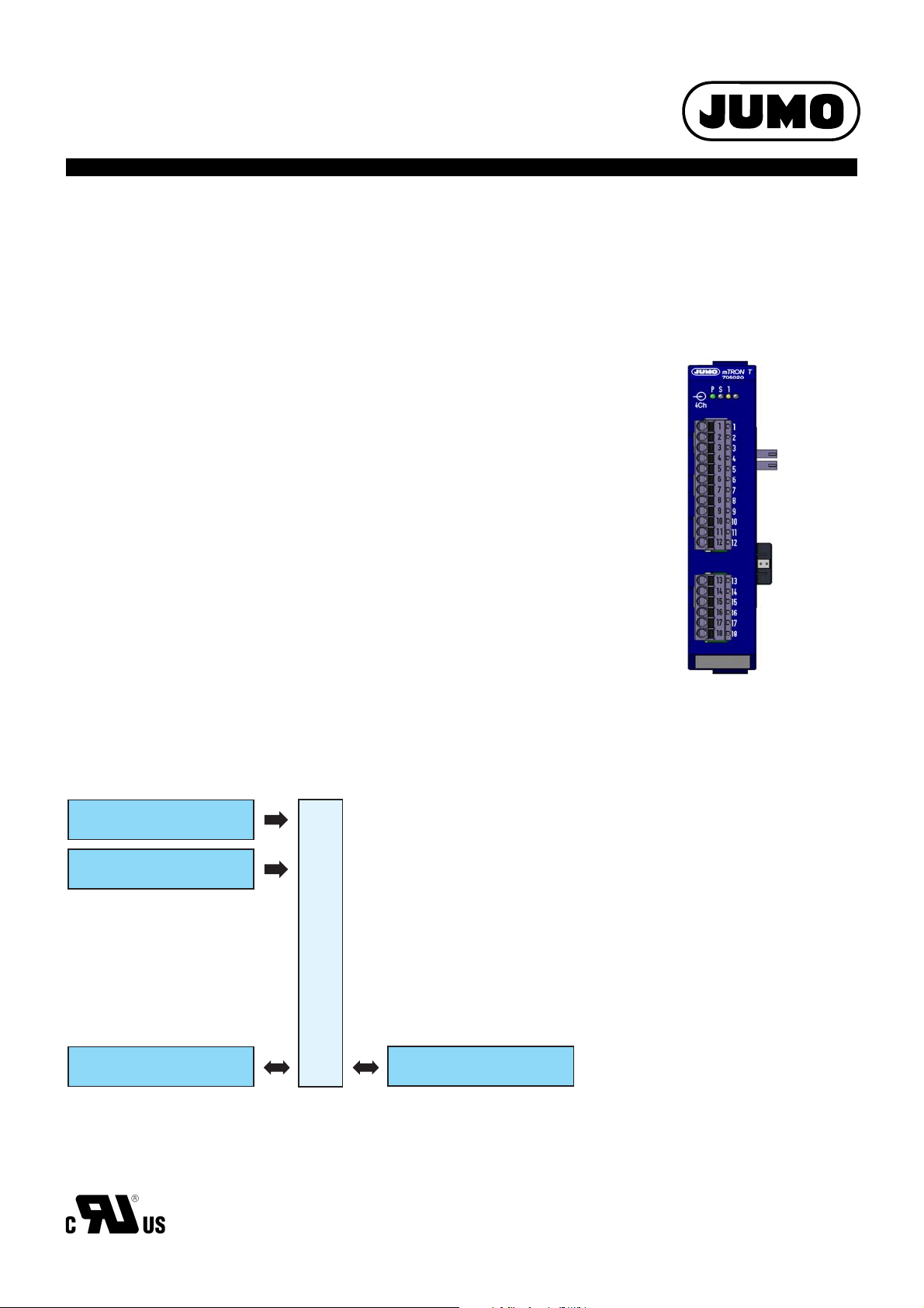
Analog input module 4-channel
Brief description
The analog input module 4-channel is equipped with four universal analog inputs that are electrically isolated from each other for thermocouples, RTD temperature probes, resistance transmitters, resistance/potentiometers, or standard signals (current or voltage) as well as one digital
input (DC 0/24 V). The digitized input values/states are available in the system for f urther processing.
LEDs are used to indicate applied voltage supply, the module operating status, as well as the
logical status of the digital input.
A setup program can be used to comfortably configure the analog input module.
For service work, the module insert can be easily pulled out of the case at the front. The case
including the bus PCB remains mounted on the DIN rail.
Page 1/10
Block diagram
Approval/approval marks (see “Technical data”)
Type 705020/...
Features
• Four high-quality, universal analog inputs
for thermocouples, RTD temperature
probes, resistance transmitters, resistance/
potentiometers, or standard signals
• All analog inputs are electrically isolated
from each other
• Customer-specific linearization (up to 45
pairs of values or polynomial up to the 4th
order)
• Limit value monitoring
• One digital input DC 0/24 V
• Automatic configuration after the module
insert has been exchanged (Plug and Play)
• Connection of the inputs at the front
• Removable terminal strips with Push-In
technology
• Quick wiring of operating voltage and system bus due to easy module connection
2013-05-07/00529109
Page 2

JUMO GmbH & Co. KG
Delivery address: Mackenrodtstraße 14
36039 Fulda, Germany
Postal address:
36035 Fulda, Germany
Phone: +49 661 6003-0
Fax: +49 661 6003-607
E-mail: mail@jumo.net
Internet: www.jumo.net
JUMO Instrument Co. Ltd.
JUMO House
Temple Bank, Riverway
Harlow, Essex CM20 2DY, UK
Phone: +44 1279 635533
Fax: +44 1279 635262
E-mail: sales@jumo.co.uk
Internet: www.jumo.co.uk
JUMO Process Control, Inc.
6733 Myers Road
East Syracuse, NY 13057, USA
Phone: 315-437-5866
1-800-554-5866
Fax: 315-437-5860
E-mail: info.us@jumo.net
Internet: www.jumousa.com
Description
Limit value monitoring
For each analog input, two separate alarms
(min/max alarm) can be activated; each alarm
has its own limit value. Alarm type, event text,
collective alarm, alarm suppression, and
alarm delay are configurable.
Analog inputs
The four analog inputs are universal measuring inputs for RTD temperature probes, thermocouples, resistance transmitters,
resistance/potentiometers, and standard signals (current, voltage). Linearizations for over
20 common measuring probes (RTD temperature probes, thermocouples) are saved. A
measured value offset or a fine adjustment
can be carried out to compensate for plantspecific deviations. Due to the measuring circuit monitoring, a measuring range that is too
high or too low, probe/cable break, and probe/
cable short circuit are detected – depending
on the measuring element type – so that the
system is switched to an operational safe status in the event of an error.
Data Sheet 705020 Page 2/10
Customer-specific linearization
A customer-specific linearization is also possible. The required linearization curve can be
entered in the setup program using up to 45
pairs of values or a formula (polynomial up to
the 4th order).
Digital input
In addition, a digital input DC 0/24 V is available. The signal status can be used in the system in a flexible manner.
2013-05-07/00529109
Page 3
JUMO GmbH & Co. KG
Delivery address: Mackenrodtstraße 14
36039 Fulda, Germany
Postal address:
36035 Fulda, Germany
Phone: +49 661 6003-0
Fax: +49 661 6003-607
E-mail: mail@jumo.net
Internet: www.jumo.net
JUMO Instrument Co. Ltd.
JUMO House
Temple Bank, Riverway
Harlow, Essex CM20 2DY, UK
Phone: +44 1279 635533
Fax: +44 1279 635262
E-mail: sales@jumo.co.uk
Internet: www.jumo.co.uk
JUMO Process Control, Inc.
6733 Myers Road
East Syracuse, NY 13057, USA
Phone: 315-437-5866
1-800-554-5866
Fax: 315-437-5860
E-mail: info.us@jumo.net
Internet: www.jumousa.com
Data Sheet 705020 Page 3/10
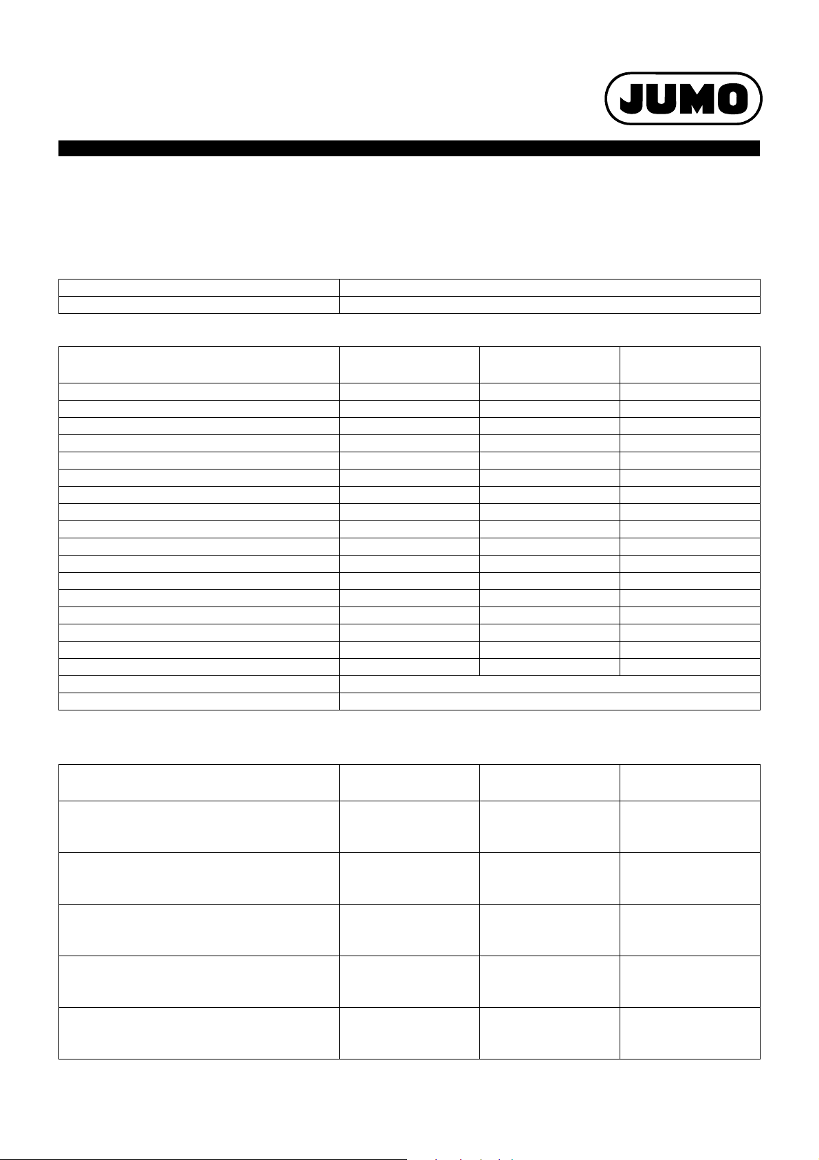
Technical data
Analog inputs
General information
Number 4
A/D converter Dynamic resolution up to 16 bit
Thermocouples
a
Designation Standard Measuring range Measuring accuracy
Fe-CuNi “L” -200 to +900 °C 0.1 % from -100 °C 300 ppm/K
Fe-CuNi “J” DIN EN 60584 -200 to +1200°C 0.1 % from -100 °C 300 ppm/K
Cu-CuNi “U” -200 to +600 °C 0.1 % from -130 °C 300 ppm/K
Cu-CuNi “T” DIN EN 60584 -200 to +400 °C 0.1 % from -150 °C 300 ppm/K
NiCr-Ni “K” DIN EN 60584 -200 to +1372 °C 0.1 % from -80 °C 300 ppm/K
NiCr-CuNi „E“ DIN EN 60584 -200 to +1000 °C 0.1 % from -80 °C 300 ppm/K
NiCrSi-NiSi “N” DIN EN 60584 -100 to +1300 °C 0.1 % from -80 °C 300 ppm/K
Pt10Rh-Pt “S” DINEN 60584 -50 to 1768 °C 0.15 % from 20 °C 300 ppm/K
Pt13Rh-Pt “R” DIN EN 60584 -50 to 1768 °C 0.15 % from 20 °C 300 ppm/K
Pt30Rh-Pt6Rh “B” DIN EN 60584 0 to 1820 °C 0.15 % from 400 °C 300 ppm/K
W5Re-W26Re „C“ 0 to 2320 °C 0.15 % from 500 °C 300 ppm/K
W3Re-W25Re “D” 0 to 2495 °C 0.15 % from 500 °C 300 ppm/K
W3Re-W26Re 0 to 2400 °C 0.15 % from 500 °C 300 ppm/K
Chromel-Copel GOST 8.585-2001 -200 to +800 °C 0.15 % from -80 °C 300 ppm/K
Chromel-Alumel GOST 8.585-2001 -200 to +1372 °C 0.10 % from -80 °C 300 ppm/K
PLII (Platinel II) 0 to 1395 °C 0.10 % from -80 °C 300 ppm/K
Linear 0 to 75 mV 0.1 % 300 ppm/K
Cold junction Pt100 internal
Cold junction accuracy 1 K
a
The accuracy values refer to the maximum measuring range. Smaller measuring ranges lead to reduced linearization accuracy.
Ambient
temperature influence
RTD temperature probe
Designation Standard Measuring range Measuring accuracy
Pt100 DIN EN 60751 -200 to +850 °C 50 ppm/K
2-wire circuit 0.15 %
3-wire/4-wire circuit 0.05 %
Pt500 DIN EN 60751 -200 to +850 °C 50 ppm/K
2-wire circuit 0.30 %
3-wire/4-wire circuit 0.15 %
Pt1000 DIN EN 60751 -200 to +850 °C 50 ppm/K
2-wire circuit 0.20 %
3-wire/4-wire circuit 0.08 %
Ni 100 DIN 43760 -60 to +250 °C 50 ppm/K
2-wire circuit 0.36 %
3-wire/4-wire circuit 0.24 %
Pt100 JIS 1604 -200 to +650 °C 50 ppm/K
2-wire circuit 0.20 %
3-wire/4-wire circuit 0.06 %
2013-05-07/00529109
a
Ambient
temperature influence
Page 4

JUMO GmbH & Co. KG
Delivery address: Mackenrodtstraße 14
36039 Fulda, Germany
Postal address:
36035 Fulda, Germany
Phone: +49 661 6003-0
Fax: +49 661 6003-607
E-mail: mail@jumo.net
Internet: www.jumo.net
JUMO Instrument Co. Ltd.
JUMO House
Temple Bank, Riverway
Harlow, Essex CM20 2DY, UK
Phone: +44 1279 635533
Fax: +44 1279 635262
E-mail: sales@jumo.co.uk
Internet: www.jumo.co.uk
JUMO Process Control, Inc.
6733 Myers Road
East Syracuse, NY 13057, USA
Phone: 315-437-5866
1-800-554-5866
Fax: 315-437-5860
E-mail: info.us@jumo.net
Internet: www.jumousa.com
Data Sheet 705020 Page 4/10
Designation Standard Measuring range Measuring accuracy
a
Ambient
temperature influence
Pt50 GOST 6651-94 -200 to +1100 °C 50 ppm/K
2-wire circuit 0.30 %
3-wire/4-wire circuit 0.06 %
Pt100 GOST 6651-94 -200 to +850 °C 50 ppm/K
2-wire circuit 0.15 %
3-wire/4-wire circuit 0.05 %
Cu50 GOST 6651-94 -50 to +200 °C 200 ppm/K
2-wire circuit 0.80 %
3-wire/4-wire circuit 0.60 %
Cu100 GOST 6651-94 -50 to +200 °C 200 ppm/K
2-wire circuit 0.80 %
3-wire/4-wire circuit 0.50 %
KTY11-6 -50 to +150 °C 50 ppm/K
2-wire circuit 1%
3-wire/4-wire circuit 0.24 %
Sensor lead resistance Max. 30 per lead with a 3-wire and 4-wire circuit
Max. 10 per lead with a 2-wire circuit
Measuring current Pt100 approx. 250 A, Pt500, and Pt1000 approx. 100 A; not constant
Lead compensation Not required for 3-wire and 4-wire circuit. For a 2-wire circuit, the lead resistance can
be compensated in the software by correcting the process value.
a
The accuracy values refer to the maximum measuring range. Smaller measuring ranges lead to reduced linearization accuracy.
Standard signals
Designation Measuring range Measuring accuracy
Voltage 0.05 % 100 ppm/K
Input resistance R
Input resistance R
> 500 k DC 0(2) to 10 V
E
> 100 k DC0to1V
E
Current (voltage drop 2V) DC0(4)to20mA 0.05 % 100 ppm/K
Resistance transmitter min. 100 , max. 4 k4 100 ppm/K
Resistance/potentiometer 400
400 to 4 k
a
The accuracy values refer to the maximum measuring range. Smaller measuring ranges lead to reduced linearization accuracy.
0.4
4
a
Ambient
temperature influence
50 ppm/K
50 ppm/K
Measuring circuit monitoring
In the event of an error the digitized output values move to a defined status.
Measuring element Out of range Probe/cable short circuit Probe/cable break
Thermocouple Is detected Is not detected Is detected
RTD temperature probe Is detected Is detected Is detected
Voltage
2 to 10 V Is detected Is detected Is detected
0 to 10 V Is detected Is not detected Is not detected
0 to 1 V Is detected Is not detected Is not detected
Current
4 to 20 mA Is detected Is detected Is detected
0 to 20 mA Is detected Is not detected Is not detected
Resistance transmitter Is detected Is not detected Is detected
Resistance/potentiometer Is detected Is detected Is detected
2013-05-07/00529109
Page 5

JUMO GmbH & Co. KG
Delivery address: Mackenrodtstraße 14
36039 Fulda, Germany
Postal address:
36035 Fulda, Germany
Phone: +49 661 6003-0
Fax: +49 661 6003-607
E-mail: mail@jumo.net
Internet: www.jumo.net
JUMO Instrument Co. Ltd.
JUMO House
Temple Bank, Riverway
Harlow, Essex CM20 2DY, UK
Phone: +44 1279 635533
Fax: +44 1279 635262
E-mail: sales@jumo.co.uk
Internet: www.jumo.co.uk
JUMO Process Control, Inc.
6733 Myers Road
East Syracuse, NY 13057, USA
Phone: 315-437-5866
1-800-554-5866
Fax: 315-437-5860
E-mail: info.us@jumo.net
Internet: www.jumousa.com
Data Sheet 705020 Page 5/10
Digital input
Number 1
Input signal DC 0/24 V
(PLC level; logical “0” = -3 to +5 V; logical “1” = +15 to +30 V)
Electrical data
Voltage supply
Connection Lateral (feed via base unit or router module)
Voltage DC 24 V +25/-20 %
Residual ripple 5 %
Current consumption 130 mA (at DC 19.2 V)
Power consumption 3 W
Inputs (terminals 1 to 18)
Connection At the front (removable terminal strips with Push-In technology)
Conductor cross section on terminals 1 to 18
Wire or strand without ferrule Min. 0.14 mm
Strand with ferrule Without plastic collar: Min. 0.25 mm2, max. 1.5 mm
With plastic collar: Min. 0.25 mm2, max. 0.5 mm
Stripping length on terminals 1 to 18 9 mm
Electrical safety Acc. to DIN EN 61010-1
Overvoltage category III, pollution degree 2
Electromagnetic compatibility Acc. to DIN EN 61326-1
Interference emission Class A – only for industrial use –
Interference immunity Industrial requirements
2
, max. 1.5 mm
2
2
2
Case and ambient conditions
Case type Plastic case for DIN rail mounting in the control cabinet (indoor use); DIN rail acc. to
Dimensions (W × H × D) 22.5 m × 103.6 m × 101.5 m (without connection elements)
Weight Approx. 140 g
Protection rating IP 20, acc. to DIN EN 60529
Ambient temperature range -20 to +55 °C
Storage temperature range -40 to +70 °C
Resistance to climatic conditions Relative humidity 90 % annual average without condensation (climatic class 3K3
Site altitude Up to 2000 m above sea level
Mechanical ambient conditions
a
Test conditions are listed in the System Descripton B 705000.8.
a
DIN EN 60715, 35 mm x 7.5 mm x 1 mm
acc. to DIN EN 60721-3-3 with extended temperature and humidity range)
Classification acc. to DIN EN 60721-3-3, table 6, class 3M2
Approval/approval marks
Approval mark Testing agency Certificate/certification
number
c UL us Underwriters Laboratories E201387 UL 61010-1 (3. Ed.),
Inspection basis Valid for
all types
CAN/CSA-22.2
No. 61010-1 (3. Ed.)
2013-05-07/00529109
Page 6

JUMO GmbH & Co. KG
Delivery address: Mackenrodtstraße 14
36039 Fulda, Germany
Postal address:
36035 Fulda, Germany
Phone: +49 661 6003-0
Fax: +49 661 6003-607
E-mail: mail@jumo.net
Internet: www.jumo.net
JUMO Instrument Co. Ltd.
JUMO House
Temple Bank, Riverway
Harlow, Essex CM20 2DY, UK
Phone: +44 1279 635533
Fax: +44 1279 635262
E-mail: sales@jumo.co.uk
Internet: www.jumo.co.uk
JUMO Process Control, Inc.
6733 Myers Road
East Syracuse, NY 13057, USA
Phone: 315-437-5866
1-800-554-5866
Fax: 315-437-5860
E-mail: info.us@jumo.net
Internet: www.jumousa.com
Display and connection elements
(1)
(2)
(3)
(4)
(5)
(7)
(6)
Analog input 4
Digital input
»
AC 30 V
DC 50 V
AC 30 V
DC 50 V
Analog input 3
Analog input 2
Analog input 1
»
AC 30 V
DC 50 V
»
AC 30 V
DC 50 V
»
AC 30 V
DC 50 V
Voltage supply Out
Side system bus In
Side system bus Out
Voltage supply In
Data Sheet 705020 Page 6/10
(1) Status displays (LED)
P = Voltage supply
S = Status
1 = Digital input
(LED is lit: Active)
(2) Analog input 1 to 3
(3) Voltage supply Out, DC 24 V
(4) Side system bus Out
(5) Analog input 4;
digital input
(6) Side system bus In
(7) Voltage supply In, DC 24 V
Electrical isolation
2013-05-07/00529109
Page 7

JUMO GmbH & Co. KG
Delivery address: Mackenrodtstraße 14
36039 Fulda, Germany
Postal address:
36035 Fulda, Germany
Phone: +49 661 6003-0
Fax: +49 661 6003-607
E-mail: mail@jumo.net
Internet: www.jumo.net
JUMO Instrument Co. Ltd.
JUMO House
Temple Bank, Riverway
Harlow, Essex CM20 2DY, UK
Phone: +44 1279 635533
Fax: +44 1279 635262
E-mail: sales@jumo.co.uk
Internet: www.jumo.co.uk
JUMO Process Control, Inc.
6733 Myers Road
East Syracuse, NY 13057, USA
Phone: 315-437-5866
1-800-554-5866
Fax: 315-437-5860
E-mail: info.us@jumo.net
Internet: www.jumousa.com
Data Sheet 705020 Page 7/10
U
+
-
x
U
+
-
x
I
+
-
x
E
S
A
Connection diagram
The connection diagram included in the data sheet provides initial information about the connection options. Only use the installation instructions
or the operating manual for the electrical connection. The know-how and the correct tec hnical implementation of the safety warnings/instructions
contained in these documents are the prerequisite for the installation, electrical connection, and initial start as well as for the safety during operation.
Analog inputs
Connection Input Terminals Symbol and terminal designation
Thermocouple 1
RTD temperature probe
2-wire circuit
RTD temperature probe
3-wire circuit
RTD temperature probe
4-wire circuit
2 and 3
2
3
4
1
2
3
4
1
2
3
4
1
2
3
4
6 and 7
10 and 11
14 and 15
2 and 4
6 and 8
10 and 12
14 and 16
2 to 4
6 to 8
10 to 12
14 to 16
1 to 4
5 to 8
9 to 12
13 to 16
2, 6, 10, 14
3, 7, 11, 15
2, 6, 10, 14
4, 8, 12, 16
2, 6, 10, 14
3, 7, 11, 15
4, 8, 12, 16
1, 5, 9, 13
2, 6, 10, 14
3, 7, 11, 15
4, 8, 12, 16
Voltage DC 0(2) to 10 V 1
Voltage DC 0 to 1 V 1
Current DC 0(4) to 20 mA 1
Resistance transmitter
A = Start
E = End
S = Slider
Resistance/potentiometer
2-wire circuit
1 and 2
2
3
4
5 and 6
9 and 10
13 and 14
2 and 3
2
3
4
6 and 7
10 and 11
14 and 15
3 and 4
2
3
4
1
2
3
4
1
2
3
4
7 and 8
11 and 12
15 and 16
2 to 4
6 to 8
10 to 12
14 to 16
2 and 4
6 and 8
10 and 12
14 and 16
1, 5, 9, 13
2, 6, 10, 14
2, 6, 10, 14
3, 7, 11, 15
3, 7, 11, 15
4, 8, 12, 16
2, 6, 10, 14
3, 7, 11, 15
4, 8, 12, 16
2, 6, 10, 14
4, 8, 12, 16
Resistance/potentiometer
3-wire circuit
1
2
3
4
2013-05-07/00529109
2 to 4
6 to 8
10 to 12
14 to 16
2, 6, 10, 14
3, 7, 11, 15
4, 8, 12, 16
Page 8

JUMO GmbH & Co. KG
Delivery address: Mackenrodtstraße 14
36039 Fulda, Germany
Postal address:
36035 Fulda, Germany
Phone: +49 661 6003-0
Fax: +49 661 6003-607
E-mail: mail@jumo.net
Internet: www.jumo.net
JUMO Instrument Co. Ltd.
JUMO House
Temple Bank, Riverway
Harlow, Essex CM20 2DY, UK
Phone: +44 1279 635533
Fax: +44 1279 635262
E-mail: sales@jumo.co.uk
Internet: www.jumo.co.uk
JUMO Process Control, Inc.
6733 Myers Road
East Syracuse, NY 13057, USA
Phone: 315-437-5866
1-800-554-5866
Fax: 315-437-5860
E-mail: info.us@jumo.net
Internet: www.jumousa.com
Data Sheet 705020 Page 8/10
U
+
-
x
Connection Input Terminals Symbol and terminal designation
Resistance/potentiometer
4-wire circuit
1
2
3
4
1 to 4
5 to 8
9 to 12
13 to 16
Digital input
Connection Input Terminals Symbol and terminal designation
Digital input DC 0/24 V 1 17 and 18 17
1, 5, 9, 13
2, 6, 10, 14
3, 7, 11, 15
4, 8, 12, 16
18
2013-05-07/00529109
Page 9

JUMO GmbH & Co. KG
Delivery address: Mackenrodtstraße 14
36039 Fulda, Germany
Postal address:
36035 Fulda, Germany
Phone: +49 661 6003-0
Fax: +49 661 6003-607
E-mail: mail@jumo.net
Internet: www.jumo.net
JUMO Instrument Co. Ltd.
JUMO House
Temple Bank, Riverway
Harlow, Essex CM20 2DY, UK
Phone: +44 1279 635533
Fax: +44 1279 635262
E-mail: sales@jumo.co.uk
Internet: www.jumo.co.uk
JUMO Process Control, Inc.
6733 Myers Road
East Syracuse, NY 13057, USA
Phone: 315-437-5866
1-800-554-5866
Fax: 315-437-5860
E-mail: info.us@jumo.net
Internet: www.jumousa.com
Data Sheet 705020 Page 9/10
22.5
103.6
6.6
101
94.5
101.5
14.5
Dimensions
Module overview
Base units
• Central processing unit
Data sheet 705001
Input/output modules
• Multichannel controller module
Data sheet 705010
• Relay module 4-channel
Data sheet 705015
• Analog input module 4-channel
Data sheet 705020
• Analog input module 8-channel
Data sheet 705021
• Digital input/output module 12-channel
Data sheet 705030
Special modules
• Router module
Data sheet 705040
Operating, visualization,
recording
• Multifunction panel 840
Data sheet 705060
Power supply units
• 705090/05-33
Data sheet 705090
• 705090/10-33
Data sheet 705090
2013-05-07/00529109
Page 10

JUMO GmbH & Co. KG
Delivery address: Mackenrodtstraße 14
36039 Fulda, Germany
Postal address:
36035 Fulda, Germany
Phone: +49 661 6003-0
Fax: +49 661 6003-607
E-mail: mail@jumo.net
Internet: www.jumo.net
JUMO Instrument Co. Ltd.
JUMO House
Temple Bank, Riverway
Harlow, Essex CM20 2DY, UK
Phone: +44 1279 635533
Fax: +44 1279 635262
E-mail: sales@jumo.co.uk
Internet: www.jumo.co.uk
JUMO Process Control, Inc.
6733 Myers Road
East Syracuse, NY 13057, USA
Phone: 315-437-5866
1-800-554-5866
Fax: 315-437-5860
E-mail: info.us@jumo.net
Internet: www.jumousa.com
Data Sheet 705020 Page 10/10
Order details
(1) Basic type
705020 Analog input module 4-channel
(2) Voltage supply
36 DC 24 V +25/-20 %
(1) (2)
Order code /
Order example 705020 / 36
Scope of delivery
1 analog input module, 4-channel
1 Installation Instructions B 705020.4
General accessories
Article Part no.
JUMO mTRON T system manual, English 00575577
MiniDVD with setup program (full version), programming software CODESYS V3, and detailed documenta-
tion; incl. USB cable
PC Evaluation Software PCA3000 00431882
Release automatic print for PC Evaluation Software PCA3000 00505548
PCA Communication Software PCC 00431879
Plant Visualization Software JUMO SVS3000: See data sheet 700755 USB cable A-plug mini-B-plug 3 m 00506265
00569494
2013-05-07/00529109
 Loading...