

Page 1
JUMO mTRON T
Measuring, Control, and Automation System
Multichannel Controller Module
B 705010.0
Operating Manual
2013-06-19/00575595
Page 2

Page 3

Contents
1 Introduction . . . . . . . . . . . . . . . . . . . . . . . . . . . . . . . . . . . . . . . . . . . . . . . . . . . . . .7
1.1 Available technical documentation . . . . . . . . . . . . . . . . . . . . . . . . . . . . . . . . . . . . . . . . . . . . . . . . 7
1.1.1 General information . . . . . . . . . . . . . . . . . . . . . . . . . . . . . . . . . . . . . . . . . . . . . . . . . . . . . . . . . . . . 7
1.1.2 Base units . . . . . . . . . . . . . . . . . . . . . . . . . . . . . . . . . . . . . . . . . . . . . . . . . . . . . . . . . . . . . . . . . . . 7
1.1.3 Input/output modules . . . . . . . . . . . . . . . . . . . . . . . . . . . . . . . . . . . . . . . . . . . . . . . . . . . . . . . . . . . 7
1.1.4 Special modules . . . . . . . . . . . . . . . . . . . . . . . . . . . . . . . . . . . . . . . . . . . . . . . . . . . . . . . . . . . . . . 8
1.1.5 Operating, visualization, recording . . . . . . . . . . . . . . . . . . . . . . . . . . . . . . . . . . . . . . . . . . . . . . . . 8
1.1.6 Power supply units . . . . . . . . . . . . . . . . . . . . . . . . . . . . . . . . . . . . . . . . . . . . . . . . . . . . . . . . . . . . 8
1.2 Safety information . . . . . . . . . . . . . . . . . . . . . . . . . . . . . . . . . . . . . . . . . . . . . . . . . . . . . . . . . . . . . 9
1.2.1 Warning symbols . . . . . . . . . . . . . . . . . . . . . . . . . . . . . . . . . . . . . . . . . . . . . . . . . . . . . . . . . . . . . . 9
1.2.2 Note signs . . . . . . . . . . . . . . . . . . . . . . . . . . . . . . . . . . . . . . . . . . . . . . . . . . . . . . . . . . . . . . . . . . . 9
1.2.3 Intended use . . . . . . . . . . . . . . . . . . . . . . . . . . . . . . . . . . . . . . . . . . . . . . . . . . . . . . . . . . . . . . . . 10
1.2.4 Qualification of personnel . . . . . . . . . . . . . . . . . . . . . . . . . . . . . . . . . . . . . . . . . . . . . . . . . . . . . . 10
1.3 Acceptance of goods, storage, and transport . . . . . . . . . . . . . . . . . . . . . . . . . . . . . . . . . . . . . . . 11
1.3.1 Checking the delivery . . . . . . . . . . . . . . . . . . . . . . . . . . . . . . . . . . . . . . . . . . . . . . . . . . . . . . . . . 11
1.3.2 Notes on storage and transport . . . . . . . . . . . . . . . . . . . . . . . . . . . . . . . . . . . . . . . . . . . . . . . . . . 11
1.3.3 Returning goods . . . . . . . . . . . . . . . . . . . . . . . . . . . . . . . . . . . . . . . . . . . . . . . . . . . . . . . . . . . . . 11
1.3.4 Disposal . . . . . . . . . . . . . . . . . . . . . . . . . . . . . . . . . . . . . . . . . . . . . . . . . . . . . . . . . . . . . . . . . . . . 12
1.4 Identifying the device version . . . . . . . . . . . . . . . . . . . . . . . . . . . . . . . . . . . . . . . . . . . . . . . . . . . 13
1.4.1 Nameplates . . . . . . . . . . . . . . . . . . . . . . . . . . . . . . . . . . . . . . . . . . . . . . . . . . . . . . . . . . . . . . . . . 13
1.4.2 Order details . . . . . . . . . . . . . . . . . . . . . . . . . . . . . . . . . . . . . . . . . . . . . . . . . . . . . . . . . . . . . . . . 15
1.4.3 Scope of delivery . . . . . . . . . . . . . . . . . . . . . . . . . . . . . . . . . . . . . . . . . . . . . . . . . . . . . . . . . . . . . 16
1.4.4 Accessories . . . . . . . . . . . . . . . . . . . . . . . . . . . . . . . . . . . . . . . . . . . . . . . . . . . . . . . . . . . . . . . . . 16
1.4.5 General accessories . . . . . . . . . . . . . . . . . . . . . . . . . . . . . . . . . . . . . . . . . . . . . . . . . . . . . . . . . . 16
2 Description . . . . . . . . . . . . . . . . . . . . . . . . . . . . . . . . . . . . . . . . . . . . . . . . . . . . . .17
2.1 Brief description . . . . . . . . . . . . . . . . . . . . . . . . . . . . . . . . . . . . . . . . . . . . . . . . . . . . . . . . . . . . . . 17
2.2 Block diagram . . . . . . . . . . . . . . . . . . . . . . . . . . . . . . . . . . . . . . . . . . . . . . . . . . . . . . . . . . . . . . . 17
3 Installation . . . . . . . . . . . . . . . . . . . . . . . . . . . . . . . . . . . . . . . . . . . . . . . . . . . . . .19
3.1 General information on installation/dismounting . . . . . . . . . . . . . . . . . . . . . . . . . . . . . . . . . . . . . 19
3.2 Installation/dismounting on DIN rail . . . . . . . . . . . . . . . . . . . . . . . . . . . . . . . . . . . . . . . . . . . . . . . 20
3.2.1 Input/output modules . . . . . . . . . . . . . . . . . . . . . . . . . . . . . . . . . . . . . . . . . . . . . . . . . . . . . . . . . . 20
3.3 Replacing module inserts . . . . . . . . . . . . . . . . . . . . . . . . . . . . . . . . . . . . . . . . . . . . . . . . . . . . . . 24
3.3.1 Input/output modules . . . . . . . . . . . . . . . . . . . . . . . . . . . . . . . . . . . . . . . . . . . . . . . . . . . . . . . . . . 24
3.4 Dimensions . . . . . . . . . . . . . . . . . . . . . . . . . . . . . . . . . . . . . . . . . . . . . . . . . . . . . . . . . . . . . . . . . 26
4 Electrical connection . . . . . . . . . . . . . . . . . . . . . . . . . . . . . . . . . . . . . . . . . . . . .27
4.1 Installation notes . . . . . . . . . . . . . . . . . . . . . . . . . . . . . . . . . . . . . . . . . . . . . . . . . . . . . . . . . . . . . 27
4.2 Galvanic isolation . . . . . . . . . . . . . . . . . . . . . . . . . . . . . . . . . . . . . . . . . . . . . . . . . . . . . . . . . . . . 29
4.3 Connection diagram . . . . . . . . . . . . . . . . . . . . . . . . . . . . . . . . . . . . . . . . . . . . . . . . . . . . . . . . . . 30
4.3.1 Display and connection elements . . . . . . . . . . . . . . . . . . . . . . . . . . . . . . . . . . . . . . . . . . . . . . . . 31
4.3.2 Overview of inputs and outputs . . . . . . . . . . . . . . . . . . . . . . . . . . . . . . . . . . . . . . . . . . . . . . . . . . 32
3
Page 4

Contents
4.3.3 Analog inputs . . . . . . . . . . . . . . . . . . . . . . . . . . . . . . . . . . . . . . . . . . . . . . . . . . . . . . . . . . . . . . . . 33
4.3.4 Digital inputs . . . . . . . . . . . . . . . . . . . . . . . . . . . . . . . . . . . . . . . . . . . . . . . . . . . . . . . . . . . . . . . . 34
4.3.5 Analog outputs . . . . . . . . . . . . . . . . . . . . . . . . . . . . . . . . . . . . . . . . . . . . . . . . . . . . . . . . . . . . . . 34
4.3.6 Digital outputs . . . . . . . . . . . . . . . . . . . . . . . . . . . . . . . . . . . . . . . . . . . . . . . . . . . . . . . . . . . . . . . 35
4.4 Connection examples . . . . . . . . . . . . . . . . . . . . . . . . . . . . . . . . . . . . . . . . . . . . . . . . . . . . . . . . . 36
4.4.1 Analog inputs . . . . . . . . . . . . . . . . . . . . . . . . . . . . . . . . . . . . . . . . . . . . . . . . . . . . . . . . . . . . . . . . 36
4.4.2 Digital outputs . . . . . . . . . . . . . . . . . . . . . . . . . . . . . . . . . . . . . . . . . . . . . . . . . . . . . . . . . . . . . . . 37
4.5 Functional test . . . . . . . . . . . . . . . . . . . . . . . . . . . . . . . . . . . . . . . . . . . . . . . . . . . . . . . . . . . . . . . 38
5 Operation . . . . . . . . . . . . . . . . . . . . . . . . . . . . . . . . . . . . . . . . . . . . . . . . . . . . . . .39
5.1 Display and connection elements . . . . . . . . . . . . . . . . . . . . . . . . . . . . . . . . . . . . . . . . . . . . . . . . 39
5.2 LED displays . . . . . . . . . . . . . . . . . . . . . . . . . . . . . . . . . . . . . . . . . . . . . . . . . . . . . . . . . . . . . . . . 40
5.2.1 Display modes . . . . . . . . . . . . . . . . . . . . . . . . . . . . . . . . . . . . . . . . . . . . . . . . . . . . . . . . . . . . . . . 40
5.2.2 System states and errors . . . . . . . . . . . . . . . . . . . . . . . . . . . . . . . . . . . . . . . . . . . . . . . . . . . . . . 41
5.3 Operation on the multifunction panel . . . . . . . . . . . . . . . . . . . . . . . . . . . . . . . . . . . . . . . . . . . . . . 42
5.3.1 Multichannel controller module . . . . . . . . . . . . . . . . . . . . . . . . . . . . . . . . . . . . . . . . . . . . . . . . . . 43
6 Configuration . . . . . . . . . . . . . . . . . . . . . . . . . . . . . . . . . . . . . . . . . . . . . . . . . . . .47
6.1 Analog selector . . . . . . . . . . . . . . . . . . . . . . . . . . . . . . . . . . . . . . . . . . . . . . . . . . . . . . . . . . . . . . 47
6.2 Digital selector . . . . . . . . . . . . . . . . . . . . . . . . . . . . . . . . . . . . . . . . . . . . . . . . . . . . . . . . . . . . . . . 49
6.3 "Independent controller" operating mode . . . . . . . . . . . . . . . . . . . . . . . . . . . . . . . . . . . . . . . . . . 52
6.4 Device data . . . . . . . . . . . . . . . . . . . . . . . . . . . . . . . . . . . . . . . . . . . . . . . . . . . . . . . . . . . . . . . . . 54
6.5 Analog inputs . . . . . . . . . . . . . . . . . . . . . . . . . . . . . . . . . . . . . . . . . . . . . . . . . . . . . . . . . . . . . . . . 55
6.5.1 Alarms . . . . . . . . . . . . . . . . . . . . . . . . . . . . . . . . . . . . . . . . . . . . . . . . . . . . . . . . . . . . . . . . . . . . . 60
6.5.2 Fine adjustment . . . . . . . . . . . . . . . . . . . . . . . . . . . . . . . . . . . . . . . . . . . . . . . . . . . . . . . . . . . . . . 62
6.6 Digital inputs . . . . . . . . . . . . . . . . . . . . . . . . . . . . . . . . . . . . . . . . . . . . . . . . . . . . . . . . . . . . . . . . 64
6.6.1 Alarm . . . . . . . . . . . . . . . . . . . . . . . . . . . . . . . . . . . . . . . . . . . . . . . . . . . . . . . . . . . . . . . . . . . . . . 65
6.7 HW Counter . . . . . . . . . . . . . . . . . . . . . . . . . . . . . . . . . . . . . . . . . . . . . . . . . . . . . . . . . . . . . . . . . 66
6.7.1 Alarm . . . . . . . . . . . . . . . . . . . . . . . . . . . . . . . . . . . . . . . . . . . . . . . . . . . . . . . . . . . . . . . . . . . . . . 67
6.8 Binary linkings . . . . . . . . . . . . . . . . . . . . . . . . . . . . . . . . . . . . . . . . . . . . . . . . . . . . . . . . . . . . . . . 69
6.9 Controller . . . . . . . . . . . . . . . . . . . . . . . . . . . . . . . . . . . . . . . . . . . . . . . . . . . . . . . . . . . . . . . . . . . 70
6.9.1 Controller (features) . . . . . . . . . . . . . . . . . . . . . . . . . . . . . . . . . . . . . . . . . . . . . . . . . . . . . . . . . . 70
6.9.2 Controller input . . . . . . . . . . . . . . . . . . . . . . . . . . . . . . . . . . . . . . . . . . . . . . . . . . . . . . . . . . . . . . 72
6.9.3 Self-optimization . . . . . . . . . . . . . . . . . . . . . . . . . . . . . . . . . . . . . . . . . . . . . . . . . . . . . . . . . . . . . 75
6.9.4 K-Controller . . . . . . . . . . . . . . . . . . . . . . . . . . . . . . . . . . . . . . . . . . . . . . . . . . . . . . . . . . . . . . . . . 80
6.9.5 Controller collective alarm . . . . . . . . . . . . . . . . . . . . . . . . . . . . . . . . . . . . . . . . . . . . . . . . . . . . . . 88
6.10 Setpoint values . . . . . . . . . . . . . . . . . . . . . . . . . . . . . . . . . . . . . . . . . . . . . . . . . . . . . . . . . . . . . . 90
6.10.1 Ramp function . . . . . . . . . . . . . . . . . . . . . . . . . . . . . . . . . . . . . . . . . . . . . . . . . . . . . . . . . . . . . . . 91
6.11 Limit value monitoring . . . . . . . . . . . . . . . . . . . . . . . . . . . . . . . . . . . . . . . . . . . . . . . . . . . . . . . . . 96
6.11.1 Alarm . . . . . . . . . . . . . . . . . . . . . . . . . . . . . . . . . . . . . . . . . . . . . . . . . . . . . . . . . . . . . . . . . . . . . . 99
6.11.2 Alarm and hysteresis functions . . . . . . . . . . . . . . . . . . . . . . . . . . . . . . . . . . . . . . . . . . . . . . . . . 100
6.12 Analog outputs . . . . . . . . . . . . . . . . . . . . . . . . . . . . . . . . . . . . . . . . . . . . . . . . . . . . . . . . . . . . . 102
6.13 Digital outputs . . . . . . . . . . . . . . . . . . . . . . . . . . . . . . . . . . . . . . . . . . . . . . . . . . . . . . . . . . . . . . 104
6.14 NV connecting list . . . . . . . . . . . . . . . . . . . . . . . . . . . . . . . . . . . . . . . . . . . . . . . . . . . . . . . . . . . 105
6.14.1 Analog signals . . . . . . . . . . . . . . . . . . . . . . . . . . . . . . . . . . . . . . . . . . . . . . . . . . . . . . . . . . . . . . 106
4
Page 5

Contents
6.14.2 Digital signals . . . . . . . . . . . . . . . . . . . . . . . . . . . . . . . . . . . . . . . . . . . . . . . . . . . . . . . . . . . . . . 107
6.14.3 Analog signals (overview) . . . . . . . . . . . . . . . . . . . . . . . . . . . . . . . . . . . . . . . . . . . . . . . . . . . . . 108
6.14.4 Digital signals (overview) . . . . . . . . . . . . . . . . . . . . . . . . . . . . . . . . . . . . . . . . . . . . . . . . . . . . . . 110
6.14.5 Replacement values (overview) . . . . . . . . . . . . . . . . . . . . . . . . . . . . . . . . . . . . . . . . . . . . . . . . 115
7 Parameterization . . . . . . . . . . . . . . . . . . . . . . . . . . . . . . . . . . . . . . . . . . . . . . . .117
7.1 Controller parameters . . . . . . . . . . . . . . . . . . . . . . . . . . . . . . . . . . . . . . . . . . . . . . . . . . . . . . . . 117
7.2 Controller types . . . . . . . . . . . . . . . . . . . . . . . . . . . . . . . . . . . . . . . . . . . . . . . . . . . . . . . . . . . . . 119
8 Configuration – in setup program only . . . . . . . . . . . . . . . . . . . . . . . . . . . . . .121
8.1 Customer-specific linearization . . . . . . . . . . . . . . . . . . . . . . . . . . . . . . . . . . . . . . . . . . . . . . . . . 121
8.1.1 Grid points . . . . . . . . . . . . . . . . . . . . . . . . . . . . . . . . . . . . . . . . . . . . . . . . . . . . . . . . . . . . . . . . . 123
8.1.2 Formula . . . . . . . . . . . . . . . . . . . . . . . . . . . . . . . . . . . . . . . . . . . . . . . . . . . . . . . . . . . . . . . . . . . 124
8.2 Math/Logic . . . . . . . . . . . . . . . . . . . . . . . . . . . . . . . . . . . . . . . . . . . . . . . . . . . . . . . . . . . . . . . . . 126
9 Online parameters . . . . . . . . . . . . . . . . . . . . . . . . . . . . . . . . . . . . . . . . . . . . . . .129
9.1 Calibrate / test . . . . . . . . . . . . . . . . . . . . . . . . . . . . . . . . . . . . . . . . . . . . . . . . . . . . . . . . . . . . . . 129
9.1.1 Analog input . . . . . . . . . . . . . . . . . . . . . . . . . . . . . . . . . . . . . . . . . . . . . . . . . . . . . . . . . . . . . . . 129
9.1.2 Analog output . . . . . . . . . . . . . . . . . . . . . . . . . . . . . . . . . . . . . . . . . . . . . . . . . . . . . . . . . . . . . . 131
9.1.3 Digital input . . . . . . . . . . . . . . . . . . . . . . . . . . . . . . . . . . . . . . . . . . . . . . . . . . . . . . . . . . . . . . . . 132
9.1.4 Digital output . . . . . . . . . . . . . . . . . . . . . . . . . . . . . . . . . . . . . . . . . . . . . . . . . . . . . . . . . . . . . . . 133
9.1.5 Internal Pt100 . . . . . . . . . . . . . . . . . . . . . . . . . . . . . . . . . . . . . . . . . . . . . . . . . . . . . . . . . . . . . . 134
9.1.6 LED test . . . . . . . . . . . . . . . . . . . . . . . . . . . . . . . . . . . . . . . . . . . . . . . . . . . . . . . . . . . . . . . . . . . 135
9.1.7 Calibration constants . . . . . . . . . . . . . . . . . . . . . . . . . . . . . . . . . . . . . . . . . . . . . . . . . . . . . . . . . 136
9.1.8 Versions . . . . . . . . . . . . . . . . . . . . . . . . . . . . . . . . . . . . . . . . . . . . . . . . . . . . . . . . . . . . . . . . . . 136
10 Retrofitting inputs/outputs . . . . . . . . . . . . . . . . . . . . . . . . . . . . . . . . . . . . . . . .137
11 Appendix . . . . . . . . . . . . . . . . . . . . . . . . . . . . . . . . . . . . . . . . . . . . . . . . . . . . . .141
11.1 Technical data . . . . . . . . . . . . . . . . . . . . . . . . . . . . . . . . . . . . . . . . . . . . . . . . . . . . . . . . . . . . . . 141
11.1.1 Analog inputs . . . . . . . . . . . . . . . . . . . . . . . . . . . . . . . . . . . . . . . . . . . . . . . . . . . . . . . . . . . . . . . 141
11.1.2 Digital inputs . . . . . . . . . . . . . . . . . . . . . . . . . . . . . . . . . . . . . . . . . . . . . . . . . . . . . . . . . . . . . . . 143
11.1.3 Analog outputs . . . . . . . . . . . . . . . . . . . . . . . . . . . . . . . . . . . . . . . . . . . . . . . . . . . . . . . . . . . . . 144
11.1.4 Digital outputs . . . . . . . . . . . . . . . . . . . . . . . . . . . . . . . . . . . . . . . . . . . . . . . . . . . . . . . . . . . . . . 144
11.1.5 Controller . . . . . . . . . . . . . . . . . . . . . . . . . . . . . . . . . . . . . . . . . . . . . . . . . . . . . . . . . . . . . . . . . . 145
11.1.6 Electrical data . . . . . . . . . . . . . . . . . . . . . . . . . . . . . . . . . . . . . . . . . . . . . . . . . . . . . . . . . . . . . . 145
11.1.7 Case and ambient conditions . . . . . . . . . . . . . . . . . . . . . . . . . . . . . . . . . . . . . . . . . . . . . . . . . . 146
11.1.8 Approval/approval marks . . . . . . . . . . . . . . . . . . . . . . . . . . . . . . . . . . . . . . . . . . . . . . . . . . . . . . 146
5
Page 6

Contents
6
Page 7
1.1 Available technical documentation
The documents specified below are available for the measuring, control, and automation system.
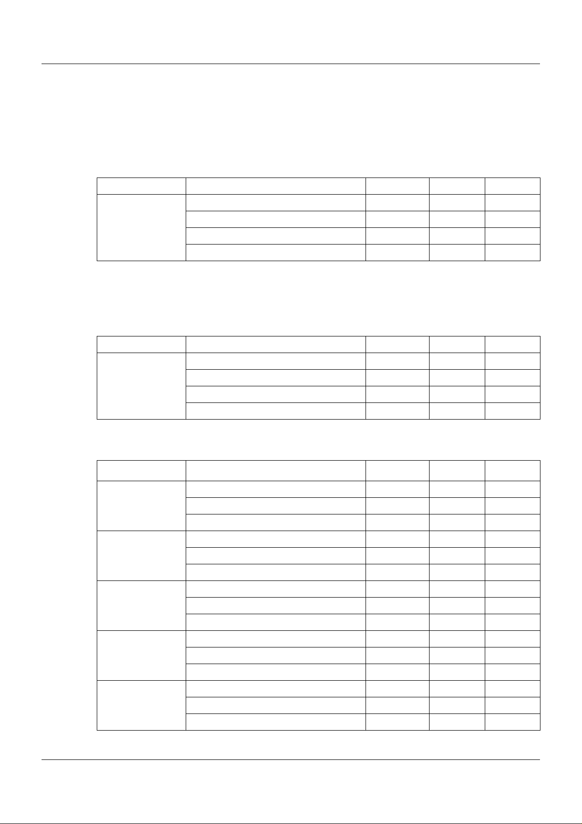
1.1.1 General information
Product Type of documentation No. Printed PDF file
Measuring,
control, and
automation system
1
Accessory subject to charge
2
Includes an overview of the purpose and content of all documents
1.1.2 Base units
Data sheet T 705000 - X
System manual
Setup program manual B 705000.6 - X
System description
1
2
1 Introduction
B 705000.0 X -
B 705000.8 - X
Product Type of documentation No. Printed PDF file
Central
processing unit
Data sheet T 705001 - X
Operating manual B 705001.0 - X
Modbus interface description B 705001.2.0 - X
Installation instructions B 705001.4 X X
1.1.3 Input/output modules
Product Type of documentation No. Printed PDF file
Multichannel
controller module
Relay module
4-channel
Analog
input module
4-channel
Data sheet T 705010 - X
Operating manual B 705010.0 - X
Installation instructions X X
Data sheet T 705015 - X
Operating manual B 705015.0 - X
Installation instructions B 705015.4 X X
Data sheet T 705020 - X
Operating manual B 705020.0 - X
Installation instructions B 705020.4 X X
Analog
input module
8-channel
Digital input/
output module
12-channel
Data sheet T 705021 - X
Operating manual B 705021.0 - X
Installation instructions B 705021.4 X X
Data sheet T 705030 - X
Operating manual B 705030.0 - X
Installation instructions B 705030.4 X X
7
Page 8
1 Introduction
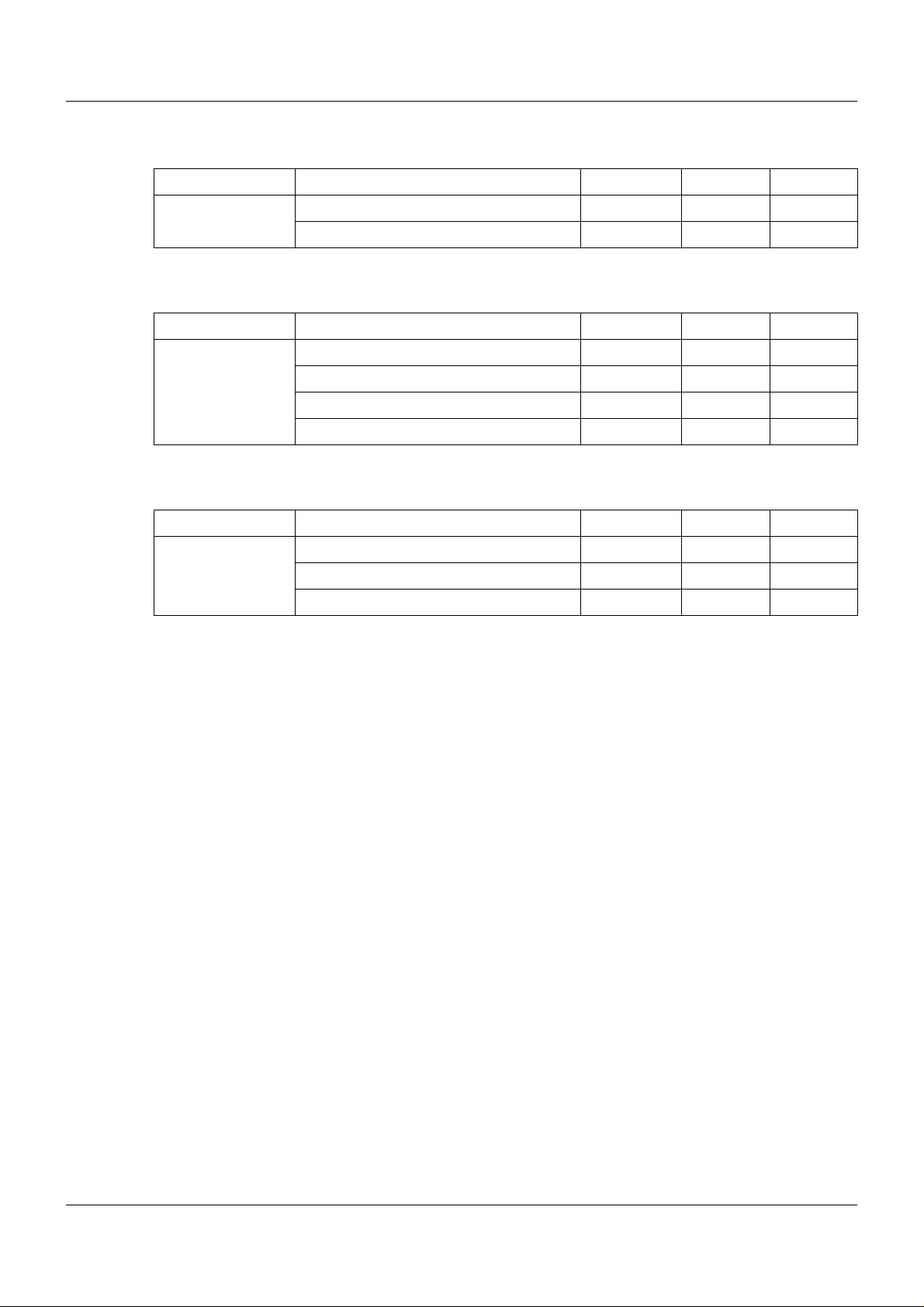
1.1.4 Special modules
Product Type of documentation No. Printed PDF file
Router module Data sheet T 705040 - X
Installation instructions B 705040.4 X X
1.1.5 Operating, visualization, recording
Product Type of documentation No. Printed PDF file
Multifunction
panel 840
Data sheet T 705060 - X
Operating manual B 705060.0 - X
Modbus interface description B 705060.2.0 - X
Installation instructions B 705060.4 X X
1.1.6 Power supply units
Product Type of documentation No. Printed PDF file
24 V power supply
units
Data sheet T 705090 - X
Operating instructions QS5.241 X Operating instructions QS10.241 X -
8
Page 9
1.2 Safety information
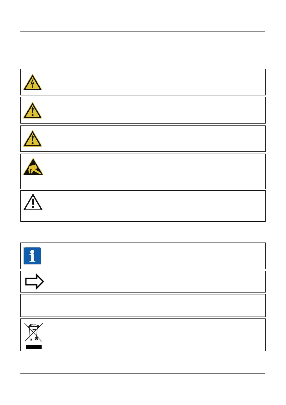
&
1.2.1 Warning symbols
DANGER!
This symbol indicates that injury to persons caused by electrical shock may occur, if the
respective protective measures are not carried out.
WARNING!
This symbol in connection with the signal word indicates that injury of persons may occur,
if the respective protective measures are not carried out.
CAUTION!
This symbol in combination with the signal word indicates that damage to assets or data
loss will occur if suitable precautions are not taken.
CAUTION!
This sign indicates that components could be destroyed by electrostatic discharge
(ESD = Electro Static Discharge), if the respective cautionary measures are not taken.
Only use the ESD packages intended for this purpose to return device inserts, assembly
groups or assembly components.
1 Introduction
READ DOCUMENTATION!
This symbol – placed on the device – indicates that the associated device documentation
has to be observed. This is necessary to recognize the kind of the potential hazards as
well as to take the measures to avoid them.
1.2.2 Note signs
TIP!
This symbol refers to important information about the product or its handling or additional
use.
REFERENCE!
This symbol refers to further information in other sections, chapters, or manuals.
FURTHER INFORMATION!
This sign is used in the tables and refers to further information in connection with the table.
DISPOSAL!
This device and, if installed, the batteries must not be disposed of in the garbage can after
use! Please ensure that they are disposed of properly and in an environmentally friendly
manner.
9
Page 10

1 Introduction
1.2.3 Intended use
The modules described are intended for measuring, control, an d automation t asks in an ind ustrial environment, as described in the technical data. Oth er uses or uses beyond th ose defined
are not viewed as intended uses.
The modules are built according to the relevant standards and directives as well as the applicable safety regulations. Nevertheless, incorrect use may lead to bodily injury or property damage.
To avoid danger, the modules may only be used:
• For the intended use
• When in good order and condition
• When taking into account the technical documentation provided
Even if a module is used correctly and according to the intended use, it may still cause appli-
cation-related dangers (e.g. due to missing safety devices or incorrect settings).
1.2.4 Qualification of personnel
This document contains the necessary information for the intended use of the modules to which
it relates.
It is intended for technically qualified personnel who have received special training and have
the appropriate knowledge in the field of automation technology (measuring, process, and control technology).
The appropriate level of knowledge and the technically fault-free implementation of the safety
information and warnings contained in the technical documentation provided are prerequisites
for risk-free mounting, installation, and startup as well as for ensuring safety when operating
the described modules. Only qualified personnel have the required specialist knowledge to correctly interpret and implement the safety information and warnings contained in this document
in specific situations.
10
Page 11

1.3 Acceptance of goods, storage, and transport
1.3.1 Checking the delivery
• Ensure that the packaging and contents are not damaged
• Check that the delivery is complete using the delivery papers and the order details
• Inform the supplier immediately if there is any damage
• Store damaged parts until clarification is received from the supplier
1.3.2 Notes on storage and transport
• Store the module in a dry and clean environment. Observe the admissible ambient conditions (see "Technical data")
• The transport of the module is to be shockproof
• The original packaging provides optimum protection for storage and transport
1.3.3 Returning goods
In the event of repair, please return the module in a clean and complete state.
Use the original packaging to return goods.
1 Introduction
Accompanying letter for repair
Please include the completed accompanying letter for repair when returning goods.
Do not forget to state the following:
• Description of the application and
• Description of the error that has occurred
The accompanying letter for repair can be downloaded online from the manufacturer's website
(use the search function if necessary).
Protection against electrostatic discharge (ESD)
(ESD = electrostatic discharge)
To prevent damage from ESD, electronic modules or components must be handled, packaged,
and stored in an ESD-protected environment. Measures against electrostatic discharge and
electrical fields are described in DIN EN 61340-5-1 and DIN EN 6 1340-5-2 "Protection of electronic devices from electrostatic phenomena".
When returning electronic modules or components, please note the following:
• Sensitive components must only be packaged in an ESD-protected environment. Workspaces such as this divert electrostatic charges to ground in a controlled manner and prevent static charges due to friction capacities.
• Only use packaging for ESD-sensitive modules/components. These must consist of conductive plastics.
No liability can be assumed for damage caused by ESD.
11
Page 12
1 Introduction
CAUTION!
Electrostatic charges occur in non-ESD protected environments.
Electrostatic discharges can damage modules or components.
For transport purposes, use only the ESD packaging provided.
1.3.4 Disposal
Disposing of the device
DISPOSAL!
Devices and/or replaced parts should not be placed in the refuse bin at the end of their service life as they consist of materials that can be recycled by specialist recycling plants.
Dispose of the device and the packaging material in a proper and environmentally friendly
manner.
For this purpose, observe the country-specific laws and regulations for waste treatment a nd
disposal.
Disposing of the packaging material
The entire packaging material (cardboard packaging, inserts, plastic film, and plastic bags) is
fully recyclable.
12
Page 13
1.4 Identifying the device version
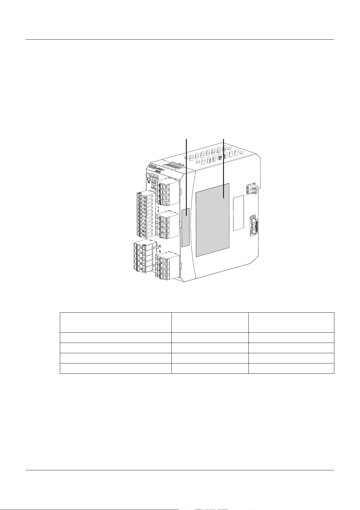
(A) (B)
1.4.1 Nameplates
Position
The nameplate (B) is affixed to the module case.
Additional nameplates with reduced information are located on the module insert (A) and inside
the module case (C; not shown). This duplicate identification marking via nameplates (A) and
(C) is important when replacing a module insert or retrofitting optional modules.
1 Introduction
Content
The nameplates contain important information. This includes:
Device type
Compare the specifications on the nameplate with the order.
Identify the supplied device version using the order details of the respective module.
Part no. (TN)
The part no. clearly identifies an article in the catalog. It is important for communication between the customer and the sales department.
Description Designation on the name-
plate
Device type (A + B + C) Typ 705010/18-113-36
Part no. (A + B + C) TN 00XXXXXX
Fabrication number (A + B + C) F-Nr 0070033801211010006
Voltage supply (B) - DC 24 V +25/-20 %
Example
13
Page 14

1 Introduction
Fabrication no. (F-Nr)
Among other things, the fabrication number contains the date of production (year/week).
Example: F-Nr = 0070033801211010006
The figures concerned are in positions 12, 13, 14, and 15 (from the left).
The device was therefore produced in the 1st calendar week of 2011.
Identifying the optional modules
The device type (Typ) also contains information about factory-fitted optional modules (in the
example above – 705010/18-113-36 – this is string 113). The optional modules can be identified by the order details.
This chapter contains additional information to identify optional modules:
Chapter 10 "Retrofitting inputs/outputs", page 137
TIP!
The information on the nameplates must also be considered when replacing the module insert
(Chapter 3.3 "Replacing module inserts", page 24).
14
Page 15

1.4.2 Order details
(1) Basic type
705010 Multichannel controller module, 2x universal input, 2x digital input, 2x relay output
(2) Basic type extension
1 2 relays (N/O contact)
2 2 logic outputs 0/15 V
(3) Version
8 With factory settings
(4) Option slot 1
0 Not used
1 Analog input 2
2 Relay (changeover contact)
3 2 relays (N/O contacts with common pole)
4 Analog output
5 2 digital inputs
6 Solid-state relay 1 A
7 2 open-collector outputs
(5) Option slot 2
0 Not used
1 Analog input 2
2 Relay (changeover contact)
3 2 relays (N/O contacts with common pole)
4 Analog output
5 2 digital inputs
6 Solid-state relay 1 A
7 2 open-collector outputs
(6) Option slot 3
0 Not used
2 Relay (changeover contact)
3 2 relays (N/O contacts with common pole)
4 Analog output
5 2 digital inputs
6 Solid-state relay 1 A
7 2 open-collector outputs
(7) Voltage supply
36 DC 24 V +25/-20 %
1 Introduction
(1) (2) (3) (4) (5) (6) (7)
Order code /- -
Order example 705010 / 1 8 - 0 0 0 - 36
15
Page 16

1 Introduction
1.4.3 Scope of delivery
1 multichannel controller module in the ordered version
1 Installation instructions B 705010.4
1.4.4 Accessories
Article Part no.
Modules for option slots (expansion boards):
Analog input 00569497
Relay (changeover contact) 00569498
2 relays (N/O contacts with common pole) 00569499
Analog output 00569500
2 digital inputs 00569501
Solid-state relay 1 A 00569502
2 open-collector outputs 00569503
1.4.5 General accessories
Article Part no.
JUMO mTRON T system manual, English 00575577
MiniDVD with setup program (full version), programming sof tware CODESYS V3, a nd
detailed documentation; incl. USB cable
PC Evaluation Software PCA3000 00431882
Release automatic print for PC Evaluation Software PCA3000 00505548
PCA Communication Software PCC 00431879
Plant Visualization Software JUMO SVS3000: See data sheet 700755 USB cable A-plug mini-B-plug 3 m 00506265
00569494
16
Page 17
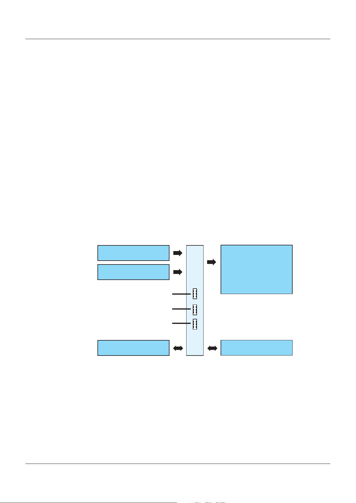
2.1 Brief description
2 universal analog inputs
Option 1
2 digital inputs
(DC 0/24 V)
2 digital outputs:
Relay
Logic
(N/O)
or
(DC 0/15 V,
to control an external
solid-state relay)
705010
Option 2
Option 3
Voltage supply
System bus
The multichannel controller module supports up to four PID controller channels (cascadable).
In the standard version, two high-quality universal analog inputs for thermocouples, RTD temperature probes, resistance transmitters, resistance/potentiometers, and standard signals are
available. Two digital inputs (DC 0/24 V) and two digital outputs as a relay with N/O contact
(AC 230 V / 3 A) or as a logic output (DC 0/15 V) are also available as part of the standard version. Due to the three option slots (option 1, 2, and 3), the module can be extended up to four
universal analog inputs, eight digital inputs, three analog outputs, or eight digital outputs.
The digitized input values/states are available in the system for further processing. The digital
and the analog outputs can be actuated by t he system (via the connection list or directly by the
PLC) or directly by the module.
The module operates independently , even if the central processing unit fails or the higher-ranking system malfunctions. This behavior can be configured.
LEDs are used to indicate applied voltage supply, the module operating status, as well as the
status of the digital inputs/outputs.
For expansion of the inputs/outputs or for service work, the module insert can be easily pulled
out of the case at the front. The case including the bus PCB remains mounted on the DIN rail.
A setup program allows the user to comfortably configure and parameterize the multichannel
controller module.
2 Description
2.2 Block diagram
17
Page 18

2 Description
18
Page 19
3 Installation
3.1 General information on installation/dismounting
DANGER!
With multichannel controller module 705010 and relay module 705015, the load circuits from
relay or solid state relay outputs can be operated with a dangerous electrical voltage (e.g.
230 V).
There is a risk of electric shock.
Prior to the installation/dismounting of these modules or the removal of the module insert, the
load circuits are to be disconnected from the voltage and the terminal strips are to be removed from the module. This work must only be performed by qualified personnel.
WARNING!
The modules must never be installed in areas with an explosion hazard.
There is the risk of an explosion.
The entire system must only be used outside of areas with an explosion hazard.
Mounting site
All modules have protection type IP20 and are only intended for use in fireproof con trol cabinets
or switch boxes. The mounting site should be virtually vibration-free. Electromagnetic fields
caused by equipment such as motors or transformers should be avoided.
Multifunction panel 840 has protection type IP67 at the front and is intended for installation in
a panel cut-out. The rear has protection type IP20.
Climatic conditions
The ambient temperature and the relative humidity at the mounting site must correspond to the
technical data. Aggressive gases and vapors have a negative ef fect on the operating life of the
modules. The mounting site must be free from dust, powder, and other suspended matter so
that the cooling slots do not become blocked.
DIN rail
All modules are mounted on a DIN rail according to DIN EN 60715 (35 mm × 7.5 mm × 1 mm).
For reasons of stability, the spacing of the fastening screws for the DIN rail should not exceed
200 mm. The minimum distances for the modules that are specified in the module-specific installation or operating instructions must be observed.
Installation position
The DIN rail should be mounted horizontally so that all modules are arranged vertically. Otherwise the admissible ambient temperature range will be restricted.
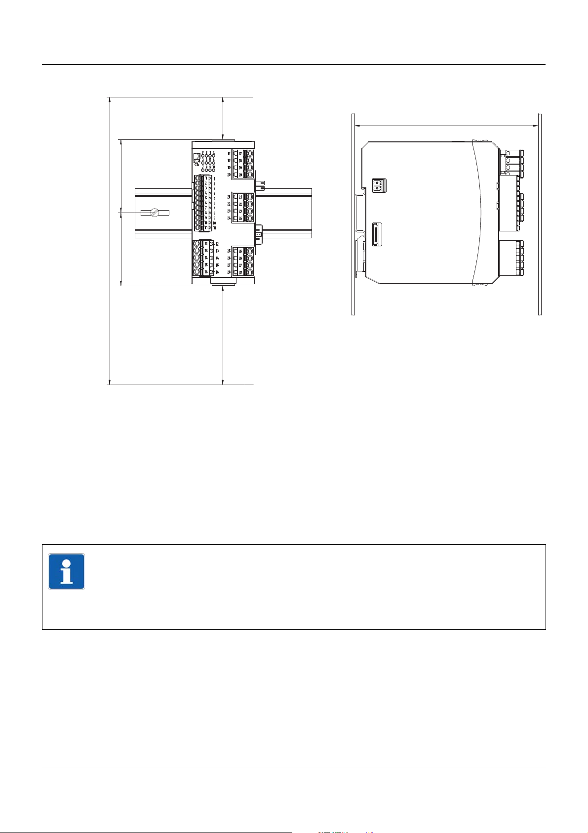
Space requirement
The modules require the minimum distances shown in the following figure for the purpose of
installation/dismounting and for future maintenance or replacement. In the event of shorter distances the minimum bending radius of the cables, the performance of the electrical inst allation,
and the clear arrangement of the plant are no longer guaranteed.
19
Page 20
3 Installation
130
203.6
51.8
30
70
51.8
Minimum distances
3.2 Installation/dismounting on DIN rail
All modules in the system are intended for installation on a DIN rail according to DIN EN 60715
(35mm×7.5mm×1mm).
The following must always be installed on the left, at the start of the DIN rail:
• A central processing unit or
• A router module
These modules connect the input/output modules to the voltage supply and the system bus.
TIP!
To determine the required minimum width of the DIN rail, the widths of the individual modules
are to be added (see technical data of the modules in the respective data sheet or the module-specific installation instructions).
The widths of the cover (17.5 mm) and both end brackets (each 9.5 mm) should also be taken into consideration: 17.5 mm + 2 × 9.5 mm = 36.5 mm.
3.2.1 Input/output modules
In a sequence at the user's discretion, input/output modules can be arranged to the right next
to a base unit or a router module.
20
Page 21
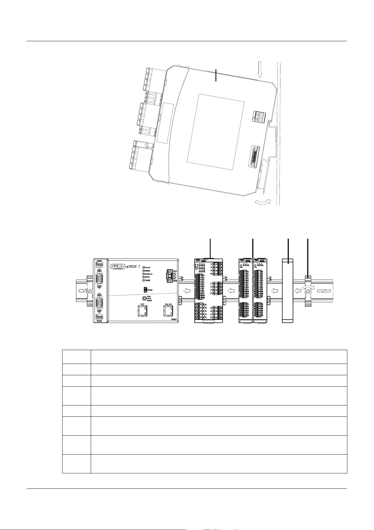
Installation, using the example of a multichannel controller module 705010
(A) (A1)
(A2)
(D)
(C5) (D6)
(D7)
(C)(A)
(B4)(A3)
(B)
3 Installation
Example installation
Procedure:
Step Activity
1 Mount the multichannel controller module (A) in the DIN rail from above (A1).
2 Pivot the multichannel controller module (A) downward until it snaps into place (A2).
3 Move the multichannel controller module (A) to the left against the previous module (A3)
until the plug connections for the voltage supply and the system bus are connected.
4 Position additional modules (B) and move to the left against the previous module (B4).
5 Aft er the final module, position the cover (C) on the DIN rail and move to the left a gainst the
module (C5).
6 After attaching the cover, positio n th e en d br ac ke t (D) on the DIN rail and mov e to th e left
against the cover (D6).
7 Fasten the end br acket ( D) using a screwdrive r (D7). For this purpose, ensure that the end
bracket and the cover are positioned flush against the final module.
21
Page 22
3 Installation
(C2)
(D1)
(A4) (B3)
(C) (D)
(A) (B)
(A)
(F)
(E)
(E5)
(F7)
(A6)
(A8)
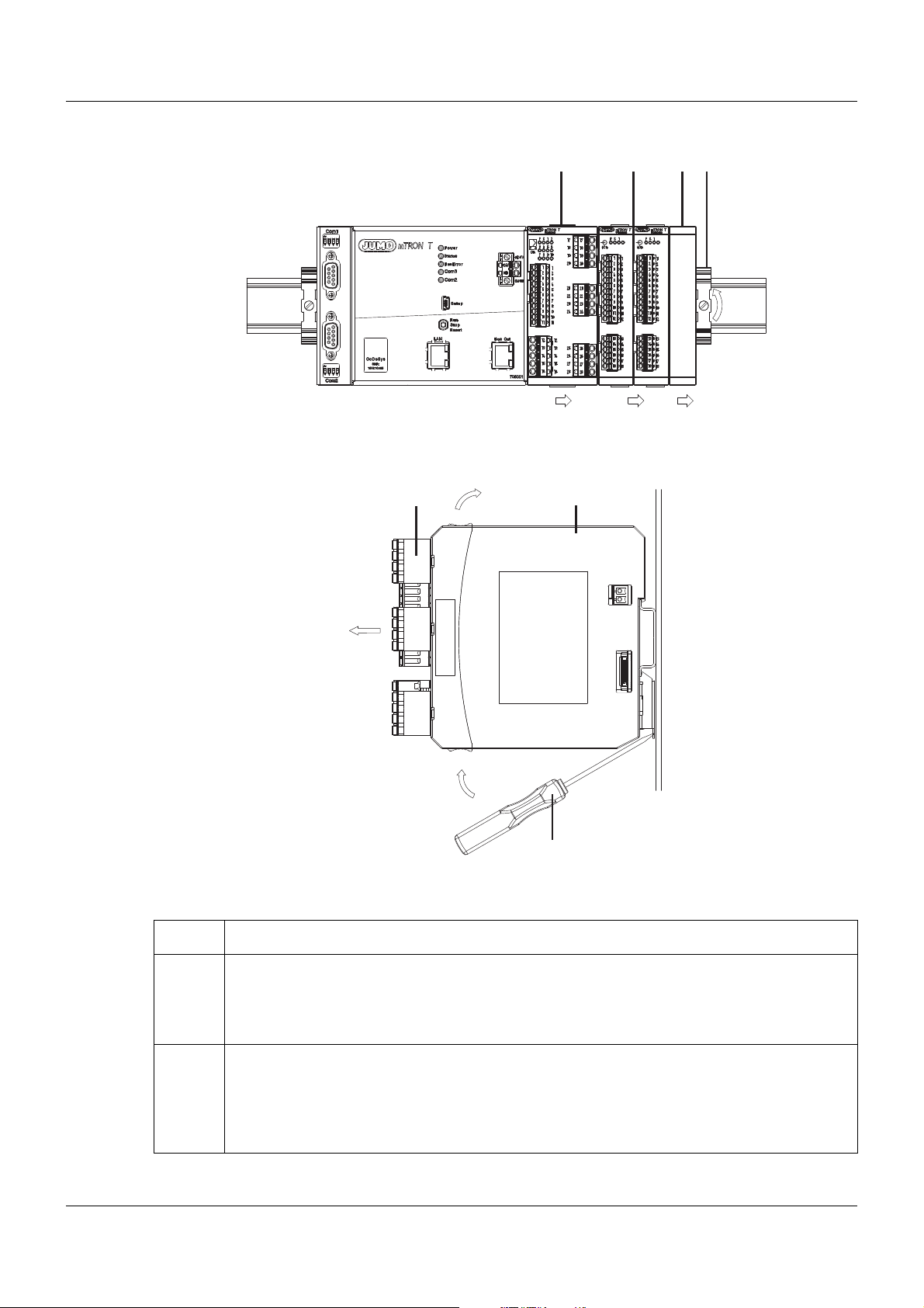
Dismounting, using the example of a multichannel controller module 705010
Removing the multichannel controller module from the DIN rail
22
Procedure:
Step Activity
1 Fully release the end bracket (D) using a screwdriver (D1) , press upward from below, pivot
2 Move the cover (C) to the right (C2) until the side contacts of the neighboring module are
toward the front, and remove from the DIN rail.
Note: The end bracket does not need to be removed from the DIN rail if there is sufficient
space to the side to move it at least 20 mm to the right.
exposed. Then release the cover at the bottom using a screwdriver, press upward, and
remove from the DIN rail.
Note: The cover does not need to be removed from the DIN rail if there is sufficient space
to the side to move it at least 20 mm to the right.
Page 23

3 Installation
Step Activity
3 Move the modules (B) on the right next to the multichannel controller module that is to be
replaced (A) a minimum of 20 mm to the right (B3).
➥ These modules are isolated from the voltage supply and the system bus.
4 Move the multichannel controller module (A) to the right (A4) until the side contacts of the
neighboring module (here: central processing unit) – on the left, next to the multichannel
controller module that is to be replaced – are exposed.
➥ The multichannel controller module is isolated from the voltage supply and the system
bus. This is a prerequisite for the dismounting of the multichannel controller module.
5 If required, pull off the wired terminals (E) of the multichannel controller module (A) toward
the front (E5).
6 Insert a suitable screwdriver (F) into the unlocking slot of the multichannel controller mod-
ule (A6) and press upward (F7).
7 Pivot the multichannel controller module (A) upward off the DIN rail (A8) and remove it.
23
Page 24
3 Installation
(A)
(E)
(B) (D)
(G)
(C)
(F)
(F)
(F)
3.3 Replacing module inserts
3.3.1 Input/output modules
DANGER!
With multichannel controller module 705010 and relay module 705015, the load circuits from
relay or solid state relay outputs can be operated with a dangerous electrical voltage (e.g.
230 V).
There is a risk of electric shock.
The load circuits are to be disconnected from the voltage supply prior to removing the wired
terminal strips. This work must only be performed by qualified personnel.
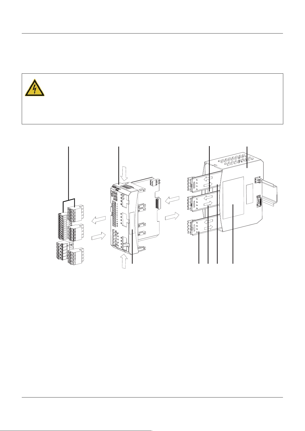
Replacement of a module insert, using the example of a multichannel controller module 705010
24
For service purposes (or when retrofitting options for the multichannel controller module), the
case (D) can remain in the system; only the module insert (B) is replaced. For this purpose, the
system does not need to be isolated from the voltage supply (hot swapping).
The system will detect a module insert of the same type that has been replaced and will automatically reconfigure it. Retrofitted functions for the multichannel controller module (exp ansion
slots) must be configured using the setup program or the multifunction panel.
The new module insert also has a new nameplate (G), which will dif fer from the old one at le ast
with regard to the fabrication number, and is no longer identical to nameplates (E) and (C) on
the case (D).
Therefore, in the event of replacement, the module insert will be supplied along with a new
nameplate that will be affixed to the case (D) in place of the old nameplate (C). This means that
the specifications of nameplates (G) and (C) once again correspond to one another.
Page 25
CAUTION!
Only module inserts of the same type may be used for the replacement.
Otherwise, the function of the system may be affected.
The module inserts can be clearly identified using the nameplate.
CAUTION!
With the multichannel controller module 705010, a new modu le insert may contain retrofitted
inputs or outputs that have not yet been configured.
This can lead to unintended behavior, particularly at the outputs and the actuators connected
to them.
Prior to using the retrofitted inputs or outputs, ensure that these have been configured correctly.
Removing the module insert
Step Activity
1 Disconnect load circuits from the relay or solid state relay outputs.
2 Pull off the wir ed terminal strips (A) toward the front.
3 Installation
3 Press the old module inse rt (B) together o n the grooved surface s at the top and bottom and
remove from the case (D).
4 For the multichannel co ntroller module, also remove the modules (F) of the exp ansion slots
from the case (D) toward the front, if required.
Mounting the module insert
Step Activity
1 Affix the new nameplate in place of the old nameplate (C) in the case.
2 For the multichannel controller module, also insert the modules (F) of the expansion slots
into the case (D), if required.
3 Hold the new module insert (B) at the grooved surfaces on the top and bottom and insert
them into the case (D). For this purpose, ensure that the board of the module insert slides
into the guide rails of the case. For the multichannel controller module, also ensure that the
modules (F) of the expansion slots slide in the guide rails of the module insert.
4 Reattach the wired terminal strips (A).
TIP!
When mounting the module insert, ensure that the snap holders (under the grooved surfaces)
audibly snap into place.
TIP!
The availability of the system can be increased through the storage of module inserts and
modules for expansion slots.
25
Page 26
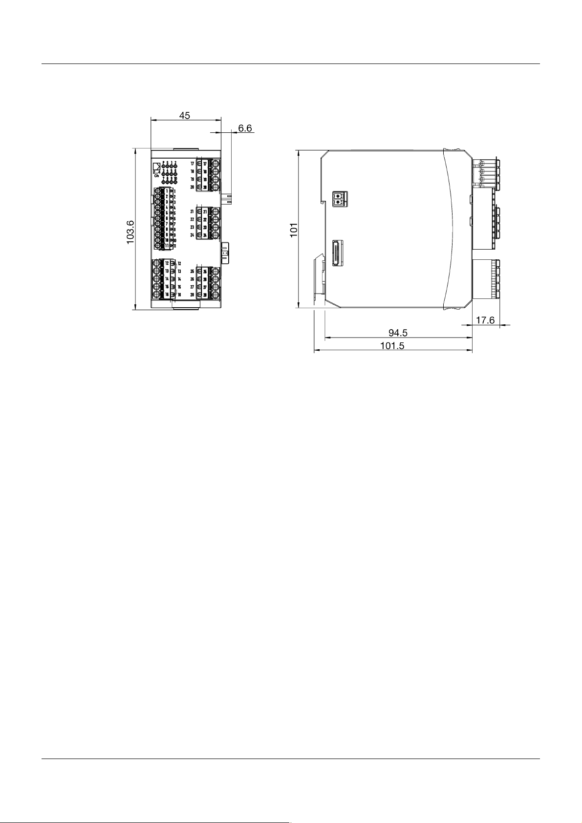
3 Installation
3.4 Dimensions
26
Page 27

4.1 Installation notes
TIP!
These installation notes apply for the entire measuring, control, and automation system and,
on some occasions, are only applicable for a specific module.
The respective connection diagram shows the context.
Qualification of personnel
• Work on the modules must only be carried out to the extent described and, like the electrical
connection, only by qualified personnel.
Cables, shielding, and grounding
• When selecting the cable material, when installing, and when performing the electrical connection of the module, the regulations of DIN VDE 0100 "Erection of power installations with
rated voltages up to 1000 V" and the respective national regulations (e.g. on the basis of
IEC 60364) are to be observed.
• Certain cables must be heat resistant up to at least 80 °C at maximum load. The relevant
instructions in the connection diagram of the affected modules must be observed.
• Route input, output, and supply cables separately and not parallel to one another.
• Only use shielded and twisted probe and interface cables. Do not route the lines close to
current-carrying components or cables.
• For temperature probes, ground the shielding on one side in the control cabinet.
• Do not perform loopthroughs on the grounding cables, but route the cables individually to a
shared grounding point in the control cabinet; in doing so, ensure that the cables are as
short as possible.
Ensure that the equipotential bonding is correct.
4 Electrical connection
Electrical safety
• Isolate power supply units from the voltage supply on the primary side if there is a risk of
touching parts with dangerous electrical voltage (e.g. 230 V) in the course of work.
• The fuse rating of the power supply units on the primary side should not exceed a value of
10 A (inert).
• With modules with relay or solid state relay outputs, the load circuits can be operated with
a dangerous electrical voltage (e.g. 230 V). Disconnect load circuits from the voltage supply
during installation/dismounting and electrical connection.
• In order to prevent the destruction of the relay or solid state relay outputs in the event of an
external short circuit in the load circuit, the load circuit should be fused to the maximum admissible output current.
• The modules are not suitable for installation in areas with an explosion hazard.
• In addition to a faulty installation, incorrectly set values on the module could also impair the
correct function of the following process. Therefore, ensure that safety devices independent
of the module (e.g. overpressure valves or temperature limiters/monitors) are available and
that it is only possible for qualified personnel to define settings. Please observe the corresponding safety regulations in this context.
27
Page 28

4 Electrical connection
References to other information
• The electromagnetic compatibility meets the standards and regulations cited in the technical data.
• The USB device interface and voltage supply in the central processing unit 705001 are not
electrically isolated. In general, please observe the specifications regarding electrical isolation.
28
Page 29
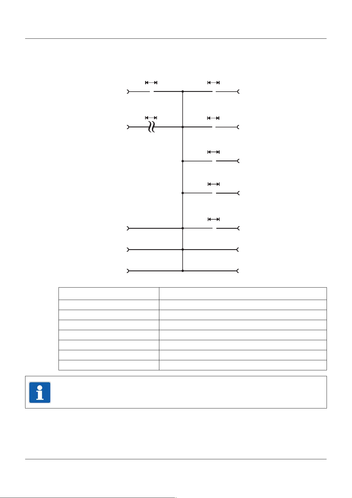
4.2 Galvanic isolation
Open-collector outputs
»
Analog inputs
Digital inputs
DC 0/24 V
Solid-state relay outputs
»
800 V (peak)
System bus
Logic outputs
DC 0/15 V
»
»
AC 30 V
DC 50 V
Voltage supply
DC 24 V
Relay outputs
»
AC 3800 V
Analog outputs
»
AC 30 V
DC 50 V
AC 30 V
DC 50 V
AC 30 V
DC 50 V
AC 30 V
DC 50 V
Voltage supply Out
Side system bus In
Side system bus Out
Voltage supply In
4 Electrical connection
Inputs/outputs Galvanically isolated from each other
Relay outputs Yes
Logic outputs DC 0/15 V Yes
Solid state relay outputs Yes
Open-collector outputs Outputs of different expansion slots
Analog outputs Yes
Digital inputs DC 0/24 V Inputs of different modules (motherboard, expansion slots)
Analog inputs Yes
TIP!
Signals to digital inputs belonging to one module (motherboard or expansion slot) must have
the same ground reference to avoid undefined signal levels.
29
Page 30
4 Electrical connection
4.3 Connection diagram
CAUTION!
At maximum load, the temperature may exceed 60 °C at the terminals.
As a result the insulation of the cable may be damaged.
The cable must be heat resistant up to at least 80 °C.
CAUTION!
The controller module configuration does not necessarily correspond to the intended application during initial startup (e.g. "Independent controller" operating mode active).
This may result in undefined plant behavior.
Therefore, where possible during startup, no actuators should be connected and load current
circuits should be isolated. The plant installer is essentially responsible for the startup process.
30
Page 31

4.3.1 Display and connection elements
4 Electrical connection
(1) Terminal strip expansion slot 1
(2) Voltage supply Out, DC 24 V
(3) Terminal strip expansion slot 2
(4) Side system bus Out
(5) Terminal strip expansion slot 3
(6) Terminal strip digital outputs 3, 4
(7) Side system bus In
(8) Terminal strip analog inputs 1, 2
and digital inputs 1, 2
(9) Voltage supply In, DC 24 V
(10) Status displays (LED):
P = Voltage supply and operating mode
S = Status
1 to 10 = Digital inputs/outputs (LED is lit: active)
31
Page 32

4 Electrical connection
4.3.2 Overview of inputs and outputs
This overview shows the position of the inputs and outputs in relation to the terminal strip s. The
assignment to the individual terminals is described in the following sections.
Standard version
(1) Analog input 1
Analog input 2
Digital input 1
Digital input 2
(2) Digital output 3
Digital output 4
(3) Analog input 3 Digital input 5 Analog output 1 Digital output 5
(4) Analog input 4 Digital input 7 Analog output 2 Digital output 7
(5) Digital input 9 Analog output 3 Digital output 9
Optional
Digital input 6 Digital output 6
Digital input 8 Digital output 8
Digital input 10 Digital output 10
32
Page 33

4 Electrical connection
U
+
-
x
U
+
-
x
I
+
-
x
E
S
A
4.3.3 Analog inputs
Input 1, 2: Standard version; input 3, 4: Option
Connection Input Terminals Symbol and terminal designation
Thermocouple 1
RTD temperature probe
2-wire circuit
RTD temperature probe
3-wire circuit
RTD temperature probe
4-wire circuit
Voltage DC 0(2) to 10 V 1
Voltage DC 0 to 1 V 1
2 and 3
2
3
4
1
2
3
4
6 and 7
18 and 19
22 and 23
2 and 4
6 and 8
18 and 20
22 and 24
2, 6, 18, 22
3, 7, 19, 23
2, 6, 18, 22
4, 8, 20, 24
1
2
3
4
2 to 4
6 to 8
18 to 20
22 to 24
2, 6, 18, 22
3, 7, 19, 23
4, 8, 20, 24
1
2
3
4
1 to 4
5 to 8
17 to 20
21 to 24
1, 5, 17, 21
2, 6, 18, 22
3, 7, 19, 23
4, 8, 20, 24
1 and 2
2
3
4
5 and 6
17 and 18
21 and 22
2 and 3
2
3
4
6 and 7
18 and 19
22 and 23
1, 5, 17, 21
2, 6, 18, 22
2, 6, 18, 22
3, 7, 19, 23
Current DC 0(4) to 20 mA,
Heater current AC 0 to 50 mA12
Resistance transmitter
A = Start
E = End
3 and 4
7 and 8
3
4
1
2
3
4
19 and 20
23 and 24
2 to 4
6 to 8
18 to 20
22 to 24
3, 7, 19, 23
4, 8, 20, 24
2, 6, 18, 22
3, 7, 19, 23
4, 8, 20, 24
S = Slider
Resistance/potentiometer
2-wire circuit
1
2
3
4
2 and 4
6 and 8
18 and 20
22 and 24
2, 6, 18, 22
4, 8, 20, 24
33
Page 34

4 Electrical connection
+
-
+
U
x
U
x
+
-
+
U
x
U
x
+
-
xIx
U
,
Connection Input Terminals Symbol and terminal designation
Resistance/potentiometer
3-wire circuit
1
2
3
4
2 to 4
6 to 8
18 to 20
22 to 24
2, 6, 18, 22
3, 7, 19, 23
4, 8, 20, 24
Resistance/potentiometer
4-wire circuit
1
2
3
4
1 to 4
5 to 8
17 to 20
21 to 24
1, 5, 17, 21
2, 6, 18, 22
3, 7, 19, 23
4, 8, 20, 24
4.3.4 Digital inputs
Connection Input Terminals Symbol and terminal designation
Digital input DC 0/24 V,
standard version
(Input 1: Counting input)
Digital input DC 0/24 V,
optional
Terminals 19 and 20, 23 and
24 as well as 27 and 28 are
internally linked.
1
2
5
6
7
8
9
10
9 and 11
10 and 11
17 and 19
18 and 20
21 and 23
22 and 24
25 and 27
26 and 28
9
10
11
17, 21, 25
18, 22, 26
19, 23, 27
20, 24, 28
4.3.5 Analog outputs
Connection Output Terminals Symbol and terminal designation
Analog output
DC 0/2 to 10 V or
DC 0/4 to 20 mA
1
2
3
(configurable),
optional
34
18 and 19
22 and 23
26 and 27
18, 22, 26
19, 23, 27
Page 35

4 Electrical connection
U
+
-
x
E
C
E
C
4.3.6 Digital outputs
Standard version
In the standard version the controller module is equipped with relay or logic output s (see “Order
details”).
Connection Output Terminals Symbol and terminal designation
Relay output (N/O) 3
4
12 and 13
15 and 16
12, 15
13, 16
Logic output DC 0/15 V 3
4
12 and 13
15 and 16
12, 15
13, 16
The digital output numbering starts with 3. T his allows the direct assignment to the LEDs of the
digital outputs (LED 3 to 10).
Optional
Connection Output Terminals Symbol and terminal designation
Relay output (changeover
contact)
Relay output (N/O) 5
5
7
9
6
7
8
9
10
17 to 19
21 to 23
25 to 27
17 and 18
18 and 19
21 and 22
22 and 23
25 and 26
26 and 27
17, 21, 25
18, 22, 26
19, 23, 27
17, 21, 25
18, 22, 26
19, 23, 27
Solid-state relay 5
Open-collector output
C = Collector
E = Emitter
7
9
5
6
7
8
9
10
18 and 19
22 and 23
26 and 27
17 and 18
17 and 19
21 and 22
21 and 23
25 and 26
25 and 27
18, 22, 26
19, 23, 27
17, 21, 25
18, 22, 26
19, 23, 27
35
Page 36

4 Electrical connection
I
+
-
x
+
-
LN
p
I
I
+
-
x
+
+
-
L
N
p
I
-
+
I
+
-
x
+
+
-
L
N
p
I
-
4.4 Connection examples
This chapter provides some examples to illustrate the connection of the inputs and outputs of
the module.
TIP!
Details for the load of the inputs and outputs are given in the "Technical data" and the information for the galvanic isolation (electric strenght). This information has to be observed when
connecting. In addition, the notes in the instructions of the connected external device must be
observed (if applicable).
4.4.1 Analog inputs
The following table shows examples of the connection of a transmitter with current output (standard signal) to an analog input of the multichannel controller module. The examples – with the
exception of the 2-wire transmitter – also generally apply to a transmitter with voltage output;
in this case, however, the different terminal designations must be considered.
Input Symbol and
terminal designation
Current DC 0(4) to 20 mA 3, 7, 19, 23
4, 8, 20, 24
Current DC 0(4) to 20 mA 3, 7, 19, 23
4, 8, 20, 24
Current DC 4 to 20 mA 3, 7, 19, 23
4, 8, 20, 24
Example of external wiring
4-wire transmitter
3-wire transmitter with external
power supply
36
2-wire transmitter with external
power supply
Page 37

4 Electrical connection
I
x
I
I
U
+
-
x
+
-
L
N
N
L
N
N
L
N
E
C
E
C
R
R
The following table shows an example of the connection of a current transformer for he ater current monitoring to an analog input of the multichannel controller module.
Input Symbol and
Heater current AC 0 to 50 mA 3, 7, 19, 23
4.4.2 Digital outputs
The following table shows examples how to use the differrent digital outputs of the multichannel
controller module.
Output Symbol and
Logic output DC 0/15 V 12, 15
Relay output (changeover
contact)
Example of external wiring
terminal designation
4, 8, 20, 24
Current transformer AC/AC
Example of external wiring
terminal designation
13, 16
External solid-state relay
17, 21, 25
18, 22, 26
19, 23, 27
Relay output (N/O) 17, 21, 25
18, 22, 26
19, 23, 27
Solid-state relay 18, 22, 26
19, 23, 27
Open-collector output
17, 21, 25
18, 22, 26
C = Collector
E = Emitter
19, 23, 27
37
Page 38

4 Electrical connection
4.5 Functional test
The voltage supply must be tested on completion of the electrical connection:
Signal Meaning
The "P" LED (Power, gr een or orange) is lit The module is being supplied with voltage
The "P" LED (Power, gr een or orange) is not lit The module is not supplied with voltage or there
through the side contacts.
is a problem with the electrical function of the
LED.
Remedy:
• Check the voltage supply to the side cont act s
of the preceding module (top contact +24 V,
bottom contact GND).
• Check voltage supply at the "+24 V" and
"GND" terminals of the base unit or router
module.
• Check power supply unit and connection between the power supply unit and the base unit
or router module.
If the "Power" LED does not light up despite a
voltage supply being present, the module insert
or – if the bus board inside the case is faulty – the
entire module must be replaced.
Startup
The check described above completes the process of installation and electrical connection. For
startup, use the additional documentation (operating manual or system manual).
The "Introduction" section of this document contains an overview of all documentation for the
measuring, control, and automation system.
38
Page 39

5.1 Display and connection elements
This overview shows the position of the display and connection elements.
5 Operation
(1) Expansion slot 1:
- Analog input 3
- Digital inputs/outputs 5, 6
- Analog output 1
(3) Expansion slot 2:
- Analog input 4
- Digital inputs/outputs 7, 8
- Analog output 2
(5) Expansion slot 3:
- Digital inputs/outputs 9, 10
- Analog output 3
(7) Side system bus In (8) Analog inputs 1, 2
(9) Voltage supply In, DC 24 V (10) LEDs:
(2) Voltage supply Out, DC 24 V
(4) Side system bus Out
(6) Digital outputs 3, 4
and digital inputs 1, 2
P = Voltage supply and operating mode
S = Status
1 to 10 = Digital inputs/outputs 1 to 10
39
Page 40

5 Operation
5.2 LED displays
"P" LED (Power)
The LED is permanently lit in green or blue if the module is being supplied with voltage.
It also indicates the operating mode of the controller module:
Green: Normal operation
Blue: Independent operation
"S" LED (Status)
This LED indicates the status of the module. Diagnostics requires the setup program or a Web
browser as appropriate.
LEDs "1" to "10"
The LEDs indicate the status of the relevant digital input or output.
LED lights up yellow = digital input or output is active
5.2.1 Display modes
The following table lists all possible states of the "S" LED (Status).
Display mode Description Green sym-
bol
--- LED state not relevant --- --Off LED off
On LED on (permanently lit)
Flickering LED flickers (50 ms on, 50 ms off)
Single flickering LED flashes briefly (50 ms on, 200 ms off)
Blinking LED flashes (200 ms on, 200 ms off)
Single flash LED flashes once (200 ms on, 1000 ms off)
Double flash L ED flashes twice (on/off/on for 200 ms each
time, 1000 ms off)
Triple flash LED flashes three times (on/off/on/off/on for
200 ms each time, 1000 ms off)
Quadruple flash LED flashes four times (on/off/on/off/on/off/on for
200 ms each time, 1000 ms off)
Blinking red/green LED flashes red and green (200 ms red, 200 ms
green)
Red symbol
On green/
Single flickering red
40
LED lights up green, flashes red (50 ms red)
Page 41

5.2.2 System states and errors
The following table lists all the system states and errors that are indicated b y the "S" LED (Status). In most cases, further diagnostics must be performed with the setup program.
5 Operation
Category "S" LED
(Status)
Start error Module error (hardware does not
Start error Internal error (bootloader)
Start er ror No firmware LED Replace module
Start er ror Incorrect optional board 1, 2, 3
Bus status No connection to central processing
Bus status System in "Stop" (INIT) state – no
Bus status System in "Stop" (PREOP) state – no
Operation
(Priority 1)
Operation
(Priority 2)
Operation
(Priority 3)
Operation
(Priority 3)
Meaning Diagnos-
tics with
LED Replace module
start up)
LED Replace module
V arious errors during startup (e.g. no
memory, initialization error)
LED Check optional board and
(actual/target)
LED Check whether the central pro-
unit
LED
error, only in start phase
LED
error, only in start phase
Calibration mode LED/setup
program
Collective alarm (incl. out of range) LED/setup
program
System in "Stop" (SAFEOP) state –
no error
System in "Run" (OP) state – no
error
LED
LED
Recommended action
replace, load, or remove as
required; replace module if
necessary
cessing unit is running; check
cabling and topology
41
Page 42

5 Operation
(2)
(4)
(3)
(1)
5.3 Operation on the multifunction panel
The basic steps for operation and visualization are described in the operating manual of the
multifunction panel (B 705060.0).
This operating manual describes how to operate the controller channels of the multichannel
controller module (controller module).
Operation of the program generator and configuration of the program editor are covere d in the
operating manual for the central processing unit (B 705001.0).
Multifunction panel – "Controller" button
(1) "Controller" button (operation) (2) "Controller" menu (opened with the "Con-
troller" button)
(3) Operate multichannel controller module;
opens the controller screen
To operate the controller channels of the multichannel controller module, select the "Controller
4x ..." entry . If multiple multichannel controller modules are ava ilable, they will be arranged one
below the other and assigned different numbers. Th e multichannel controller module in this example has been assigned the number 1.
(4) Operate program generator; opens the
generator screen
Operating manual for central process-
ing unit (B 705001.0)
42
Page 43

5.3.1 Multichannel controller module
Operation of the multichannel controller module includes the following settings and functions:
• Setpoint value entry
• Display of actual value, setpoint value, output level, switch setting of outputs, self-optimization, manual mode, and ramp function
• Start of self-optimization
• Changeover to manual mode
• In manual mode: Specification of output level or actuator opening and closing
• Display of inputs and outputs (hardware) of the multichannel controller module
Controller screen – overview of controller channels 1 to 4 (controller 1 to 4)
5 Operation
This screen provides an overview of all controller channels that are switched on:
• Actual value
• Setpoint value (display or input field; depends on the configuration and user rights)
• Output level
• Switch setting for outputs of the controller channel (K1, K2)
• Self-optimization, manual mode, ramp function (active/not active)
Controller channel 4 is switched on in this example; the actual value and setpoint value have
not yet been configured.
To select a particular controller channel, select the relevant tab at the top of the window. If a
controller channel is switched off, a gray area appea rs in the overview and the t ab is not ava ilable. If only one controller channel is switched on, the controller screen for that particular controller channel is displayed instead of this overview.
Select the tab on the right to open an overview screen with the inputs and outputs of the multichannel controller module.
43
Page 44

5 Operation
(8)
(1)
(7)
(6)
(5)
(2)
(3)
(4)
(3)
(1)
(2)
Controller screen – controller channel 1: Two-state controller in automatic mode
(1) Switch setting of output 1 (K1)
and 2 (K2) of the controller channel
(3) Changeover to manual mode (4) Self-optimization start/stop
(5) Display of output level (bar graph) (6) Display of output level (percent)
(7) Input field for setpoint value or setpoint
value display (depends on configuration)
(2) Display of self-optimization, manual mode,
ramp function (from left to right)
(8) Display of actual value
Controller screen – controller channel 2: Two-state controller in manual mode
44
(1) Manual mode is active (2) Changeover to automatic mode
(3) Input field for output level
Page 45

Controller screen – controller channel 3: Modulating controller in manual mode
(1)
(2)
(1) Open actuator (2) Close actuator
5 Operation
TIP!
If the modulating controller is in manual mode, the actuator can also be opened and closed
in the "Stop" system state.
TIP!
If the output level feedback of the position controller is "out of range", the current position of
the actuator can no longer be determined. In this case, the actuator can be operated with buttons (1) and (2), as for the three-step controller. The commands "Open actuator" or "Close
actuator" are issued for as long as the relevant button is held.
45
Page 46

5 Operation
Controller screen – overview of the inputs and outputs of the multichannel controller module
This screen provides an overview of the inputs and outputs o f the multichannel controller module:
• Measured value of analog inputs (including display of measuring range overflow and underflow)
• Signal of analog outputs (optional)
• Switching status of digital inputs and outputs
Information about controller channels 1 to 4 is also displayed:
• Number of the active parameter block
• Number of the active setpoint value (when using the setpoint value function)
46
Page 47

TIP!
The parameters described in this section can be configured either with the setup program or
with the multifunction panel (exception: Device data and replacement values).
6.1 Analog selector
The analog selector contains all analog signals that are available in the multichannel controller
module for configuration.
The following table lists all analog signals. The entry in the "Type" column indicates the source
of the signal:
• Internal only: Internal signal that is only available inside the multichannel controller module.
• Internal: Internal signal of the multichannel controller module (including signals of analog
inputs)
The signal is also transmitted to the base unit via the system bus, to allow it to be used by
other modules.
• External: External input (NV_...) that must be linked in the NV connecting list to a signal
from another module (see Chapter 6.14 "NV connecting list", page 105).
The signal name "NV_..." indicates the intended use; in principle, the signal can also be
used for other purposes.
6 Configuration
Category Signal Type Description
Inactive No signal selected
Further signals Samp ling Ra te Internal
only
Controller NV_C01ActualValue to
NV_C04ActualValue
NV_C01Setpoint to
NV_C04Setpointt
C01OutpLevelMon to
C04OutpLevelMon
C01OutpLevel1 to
C04OutpLevel1
C01OutpLevel2 to
C04OutpLevel2
C01Diff to C04Diff Internal Difference between setpoint value
External Actual value for controller channel
External Setpoint value for controller chan-
Internal Output level (display value) of
Internal Output level at first controller out-
Internal Ou tput level on second controller
Sampling rate of controller
module
1 to 4
nel 1 to 4
controller channel 1 to 4
put (continuous) of controller
channel 1 to 4
output (continuous) of controller
channel 1 to 4
and actual value of controller
channel 1 to 4
47
Page 48

6 Configuration
Category Signal Type Description
Setpoints NV_SP01Ext to NV_SP04Ext External External setpoint value for set-
point value function 1 to 4
SP01RampOutput to
SP04RampOutput
SP01Active to SP04Active Internal Active setpoint value (external
SP01Setpoint1 to SP04Setpoint1 Internal Setpoint value 1 (fixed setpoint
SP01Setpoint2 to SP04Setpoint2 Internal Setpoint value 2 (fixed setpoint
SP01Setpoint3 to SP04Setpoint3 Internal Setpoint value 3 (fixed setpoint
SP01Setpoint4 to SP04Setpoint4 Internal Setpoint value 4 (fixed setpoint
Analog inputs AI01 to AI04 Internal Measured value of analog input 1
Mathematics Math01 to Math04 Internal Result of math function 1 to 4
NV_M01Flag to NV_M04Flag External Any analog value 1 to 4
Hardware counter
NVAnalogOutputs
HWCounter Internal Counter reading of hardware
NV_AO01 to NV_AO03 External Signal for controlling analog out-
Internal Current setpoint value of ramp
function 1 to 4
setpoint value + setpoint value) of
setpoint value function 1 to 4
value or correction value) of setpoint value function 1 to 4
value or correction value) of setpoint value function 1 to 4
value or correction value) of setpoint value function 1 to 4
value or correction value) of setpoint value function 1 to 4
to 4
(freely available)
counter
put 1 to 3
48
Page 49

6.2 Digital selector
The digital selector contains all digital signals that are available in the multichannel controller
module for configuration.
The following table lists all digital signals. The entry in the "Type" column indicates the source
of the signal:
• Internal only: Internal signal that is only available inside the multichannel controller module.
• Internal: Internal signal of the multichannel controller module (including signals of digital inputs).
The signal is also transmitted to the base unit via the system bus, to allow it to be used by
other modules.
• External: External input (NV_...) that must be linked in the NV connecting list to a signal
from another module (see Chapter 6.14 "NV connecting list", page 105).
The signal name "NV_..." indicates the intended use; in principle, the signal can also be
used for other purposes.
Category Signal Type Description
Inactive No signal selected
Further signals Master No tCo n ne cte d Internal
Controller C01ContrLoopMonit to
C04ContrLoopMonit
only
Internal
only
6 Configuration
No connection to the base unit via
the system bus (controller module
operates independently)
Alarm signal of control loop monitoring of controller channel 1 to 4
C01OutpLevelMonit to
C04OutpLevelMonit
C01ManualMode to
C04ManualMode
C01TuneActive to C04TuneActive Internal Self-optimization active for con-
C01Output1 to C04Output1 Internal Switch position of first controller
C01Output2 to C04Output2 Internal Switch position of second control-
C01CollAlarm to C04CollAlarm Internal Collective alarm of controller
Internal
only
Internal Manual mode active on controller
Alarm signal of output level monitoring of controller channel 1 to 4
channel 1 to 4
troller channel 1 to 4
output of controller channel 1 to 4
ler output of controller channel 1
to 4
channel 1 to 4 (configurable with
signals from the digital selector)
49
Page 50

6 Configuration
?
?
Category Signal Type Description
Controller
(continued)
Setpoints SP01RampTolBa n d to
Analog inputs AI01Alarm1 to AI04Alarm1 Internal Alarm signal 1 of analog input 1 to
Digital inputs DI01, DI02, DI05 to DI10 Internal Signal of digital input 1, 2, 5 to 10
NV_C01TuneStart to
NV_C04TuneStart
NV_C01TuneStop to
NV_C04TuneStop
NV_C01ParamSet to
NV_C04ParamSet
NV_C01ManualMode to
NV_C04ManualMode
NV_C01Stop to NV_C04Stop External Switch off controller channel 1 to
SP04RampTolBand
NV_SP01Changeover1 to
NV_SP04Changeover1
NV_SP01Changeover2 to
NV_SP04Changeover2
AI01Alarm2 to AI04Alarm2 Internal Alarm signal 2 of analog input 1 to
External Start self-optimization for control-
ler channel 1 to 4
External Abort self-optimization for control-
ler channel 1 to 4
External Changeover from parameter
block 1 to parameter block 2 for
controller channel 1 to 4
External Changeover to manual mode for
controller channel 1 to 4
4
Internal Alarm signal of tolerance band
monitoring of ramp function 1 to 4
External Bit 0 of setpoint changeover of
setpoint value function 1 to 4
External Bit 1 of setpoint changeover of
setpoint value function 1 to 4
4
4
NVDigitalOutputs NV_DO03 to NV_DO10 External Signal for controlling digital output
Limit monitoring LI01 to LI04 Internal Output signal of limit value moni-
Mathematics Logic01 to Logic04 Internal Result of logic function 1 to 4
Signal rejections NV_SR01 to NV_SR08 External Signal for activating signal sup-
Alarm CollectiveAlarm Internal Controller module collective alarm
HW counter HWCounterSignal Internal Signal of hardware counter in "fill"
Digital links DigitalLink01 to DigitalLink04 Internal Result of binary linking 1 to 4
Digital inputs
If the HW counter is activated, the signal of digital input 1 is inactive.
NV_LI01Confirmation to
NV_LI04Confirmation
3 to 10
toring 1 to 4
External Signal to acknowledge the output
signal of limit value monitoring 1
to 4
pression of digital input 1, 2, 5 to
10
operating mode (as switch-off signal when threshold value
reached)
50
Page 51

Alarm
6 Configuration
The collective alarm of the controller module is made up of all functions for which the "Collective
alarm" alarm type has been activated, along with the controller channel collective alarms (collective alarm 1 to 4).
51
Page 52

6 Configuration
6.3 "Independent controller" operating mode
The controller module can be configured for independent operation. This enables it to continue
to operate if communication fails between the controller module and the central processing
unit.
Chapter 6.4 "Device data", page 54
Principle
If the "Independent controller" operating mode is enabled, the controller module can continue to perform control tasks with the remaining resources if communication fails (all internal
functions continue to run).
Otherwise, if the "Independent controller" operating mode is not enabled, the controller
channels and outputs of the controller module switch off if communication fails.
The controller module detects within 2 seconds whether the conditions for changeover to independent mode are present. These include:
• No connection to the central processing unit via the system bus (failure of all communication)
• Central processing unit changes to the "Stop" system state (failure of cyclical communication)
When changing to independent mode, the controller mo dule continues to operate with the most
recent valid setpoint inputs, provided it has been configured accordingly ("Last setpoint value
for independent mode" parameter). This affects the setpoint input both via external signals
(NV_...) and through internal functions or calculations.
A controller module that has been configured for independent mode also operates in independent mode during system startup until the "Run" system state is achieved.
Prerequisites
One prerequisite for independent mode is that the actual value of a controller channel is obtained via an analog input of the controller module. Likewise, the output level mu st be supplied
through an analog or digital output of the controller module to the control path.
If external signals (NV_...) are also used in normal operation, these are no longer a vailable after
changeover to independent operation. The relevant replacement values are used instead. You
can only configure these with the setup program and must adjust them to the relevant application with appropriate dimensioning.
Chapter 6.14.5 "Replacement values (overview)", page 115
TIP!
When configuring the controller module, a digital input for switching off the relevant controller
channel is to be included where applicable. This is the only way to ensure that a controller
channel can also be switched off when in independent mode.
Display of operating mode
In addition to the voltage supply, the two-color "P" LED (Power) also indicates the operating
mode of the controller module:
• Green: Normal operation, communication present with the central processing unit
• Orange: Independent operation, no communication with the central processing unit
The operating mode is also displayed on the multifunction panel.
52
Page 53

Self-optimization
If the "Independent controller" operating mode is enabled, self-optimization can be st arted at
any time, provided it is permitted in general (configuration of self-optimization). The controller
parameters determined are saved in the controller module once self-optimization is complete
and are also transmitted to the central processing unit and saved there permanently . If communication with the central processing unit is not possible, the controller parameters are sa ved in
the controller module only.
CAUTION!
When communication becomes possible again, the controller parameters saved in the central processing unit are transmitted to the controller module.
The previously determined controller parameters in the controller module are overwritten.
Repeat self-optimization if necessary.
If the controller module changes to "Independent controller" operating mode while self-optimization is in progress, the self-optimization is aborted.
If the "Independent controller" operating mode is not enabled, self-optimization can only be
started if there is communication present between the controller module and the central processing unit.
Manual mode
In "Independent controller" operating mode, the manual output level can still be changed in the
"Stop" system state and the actuator can be opened and closed.
6 Configuration
Replacing the controller module
The behavior following controller module (or module insert) replacement depends on the set
operating mode and the compatibility of the software versions in the central processing unit and
controller module:
• "Independent controller" enabled: If the software versions are incompatible, the controller module starts up with its own configuration; the system itself does not start up if an incompatible controller module software version is detected.
If the software versions are compatible and a connection is present, the controller module
adopts the configuration from the central processing unit.
• "Independent controller" not enabled: The controller module only runs under the control
of the central processing unit. This requires compatible software versions and a co nnection
to be present.
Firmware update
During a firmware update, the system enters the "Stop" state and all outputs are switched off.
Afterward, the controller module starts with the factory settings, which means that the "Independent controller" operating mode is not permitted. An "Independent controller" setting that
has been previously configured does not become active again until the configuration has been
transferred from the central processing unit to the controller module.
CAUTION!
A firmware update affects the controller module function.
The control is interrupted for up to 60 seconds.
Take control path out of operation during the firmware update!
53
Page 54

6 Configuration
?
6.4 Device data
The settings apply for the entire controller module.
Setup dialog
Parameters
Parameter Selection/settings Description
Sampling rate Sampling rate of the internal inputs and external inputs (system bus)
T50ms The signal is sampled every 50 ms.
T100ms The signal is sampled every 100 ms.
T150ms The signal is sampled every 150 ms.
T200ms The signal is sampled every 200 ms.
T250ms The signal is sampled every 250 ms.
Contr. independent
Enable "Independent controller" operating mode.
Y es "Independent controller" operating mode
No "Independent controller" operating mode
Independent controller
The controller module can operate independently , meaning t hat if communication fails between
the controller module and the central processing unit, the control task continues to be performed.
Chapter 6.3 ""Independent controller" operating mode", page 52
Status after change of configuration
The settings are available immediately after configuration.
Behavior after power on
The settings are available immediately after initialization.
is enabled.
is not enabled.
54
Page 55

6.5 Analog inputs
The analog inputs (maximum of four) are universal measuring inputs for RTD temperature
probes, thermocouples, resistance transmitters, resistance/potentiometers, and standard signals.
Setup dialog
6 Configuration
Parameters
Parameter Selection/settings Description
Sensor Selection of measuring probe for the relevant analog input
Inactive No sensor selected
RTD temp. probe 2-w RTD temperature probe in 2-wire circuit
RTD temp. probe 3-w RTD temperature probe in 3-wire circuit
RTD temp. probe 4-w RTD temperature probe in 4-wire circuit
Resistance transmitter Resistance transmitter
Thermocouple
Heater current Heater current AC 0 to 50 mA
Current 0 to 20 mA Standard signal
Current 4 to 20 mA Standard signal
Voltage 0 to 1 V Standard signal
Voltage 0 to 10 V Standard signal
Voltage 2 to 10 V Standard signal
55
Page 56

6 Configuration
?
Parameter Selection/settings Description
Linearization Available options and factory settings depend on the measuring probe selected.
Resistance/potentiometer 2-w Resistance/potentiometer in 2-wire cir-
cuit
Resistance/potentiometer 3-w Resistance/potentiometer in 3-wire cir-
cuit
Resistance/potentiometer 4-w Resistance/potentiometer in 4-wire cir-
cuit
Linear
Pt50 GOST 6651-94
Pt100 DIN EN 60751
Pt500 DIN EN 60751
Pt1000 DIN EN 60751
Pt100J JIS 1604
Pt100G GOST 6651-94
KTY Type KTY11-6
Cu50 GOST 6651-94
Cu100 GOST 6651-94
Ni100 DIN EN 60751
NiCr-CuNi_E DIN EN 60584
Cu-CuNi_T DIN EN 60584
Fe-CuNi_J DIN EN 60584
Cu_CuNi_U
Fe-CuNi_L
NiCr-Ni_K DIN EN 60584
Pt10Rh-Pt_S DIN EN 60584
Pt13Rh-Pt_R DIN EN 60584
Pt30Rh-Pt6Rh_B DIN EN 60584
NiCrSi-NiSi_N DIN EN 60584
W5Re-W26Re_C
W3Re-W25Re_D
W3Re-W26Re
Chromel-Copel GOST 8.585-2001
Chromel-Alumel GOST 8.585-2001
Platinel II
Customer-specific Customer-specific linearization using
grid points (pairs of values) or 4th order
polynomial
56
Page 57

Parameter Selection/settings Description
?
?
?
?
?
?
?
?
?
6 Configuration
Measuring range
start
Measuring range
end
Scale start Factory setting depends on sensor and linearization.
Scale end Factory setting depends on sensor and linearization.
T AG number 7 characters Identification marking (documentation in
Unit 5 characters (%) Unit for numerical representation of
Offset type Type of measured value offset
Offset -100 to 0 to +100 Correction value
Factory setting depends on sensor and linearization.
-99999 to +99999 Start value of the measuring range (for
resistance transmitter, standard signal,
and potentiometer) to detect out of
range
Factory setting depends on sensor and linearization.
-99999 to +99999 End value of measuring range (see
above) to detect out of range
-99999 to +99999 Start value of display range
-99999 to +99999 End value of display range
PLC)
measured value
Standardized Offset of standardized measured value
(after linearization)
Physical Offset of physical measured value
(before linearization)
Filter time constant
Cold junction Selection of cold junction (for thermocouple)
Ext. reference
temp.
Resistance Ra or Ro0 to 4000 For Resistance transmitter:
Resistance Rs or Rx6 to 1000 to 4000 For Resistance transmitter:
0s to 0.6 s to 100 s Time constant for adjusting the digital
input filter (0 s = filter off)
Internal Pt100 Internal Pt100 temperature probe
External constant Constant cold junction temperature
-20 to 0 to +200 Cold junction temperatures (for thermocouple and constant cold junction temperature)
Resistance Ra between sliding contact
(S) and start (A), if the sliding contact is
positioned at the start.
For Resistance/potentiometer:
Offset resistance Ro
Resistance range Rs of sliding contact
For Resistance/potentiometer:
Shifting resistance range Rx
57
Page 58

6 Configuration
?
Parameter Selection/settings Description
Resistance Re 0 to 4000 For Resistance transmitter:
Linearization
Linearization must be selected according to the sensor (measuring probe).
The predefined linearizations can be supplemented with customer-specific linearization.
Chapter 8.1 "Customer-specific linearization", page 121
Measuring range
In case of customer-specific linearization, these values can not be changed here. They are
identical to the settings made there for "Measuring range start" and "Measuring range end".
Scale
In case of customer-specific linearization, these values are initially identical to the settings
made there for "Measuring range start" and "Measuring range end". Here, the scale range can
be additionally restricted.
Resistance Re between sliding contact
(S) and end (E), if the sliding contact is
positioned at the end.
Offset type
To offset plant-specific deviations, the measured value can be offset for each analog input.
When doing this, the offset type is used to specify the type of measured value offset.
"Standardized" offset type: The measured value is offset after linearization. In the case of an
RTD temperature probe or thermocouple, the temperature value (°C or °F) determined by the
linearization is offset.
"Physical" offset type: The physical measured value is offset before linearization. In the case
of an RTD temperature probe, this relates to the resistance in ohms; in the case of a thermocouple, it relates to the thermoelectric voltage in mV.
A typical application scenario for the "physical" offset type is compensation of t he lead wire resistance in an RTD temperature probe in a 2-wire circuit.
Offset
A positive or negative form of the correction value is added to the measured value (entering a
negative correction value reduces the measured value).
Filter time constant
The filter time constant is used to adjust the digit al input filter (2nd order filter). If the input signal
changes suddenly , approx. 26 % of the change is recorded following a period that corresponds
to the filter time constant (2 × filter time constants: approx. 59 %; 5 × filter time constants:
approx. 96 %). A large filter time constant means a high level of attenuation of inte rference signals, a slow reaction time of the actual value display, and low limit frequency (low-pass filter).
58
Page 59

Resistance Ra or Ro, Rs or Rx, Re
Re
Rs
Ra
E
S
A
Rx
Ro
RoRxRo
Rx
The overall resistance Ra + Rs + Re (or Ro + Rx) must not exceed 4000 .
Resistance transmitter Resistance/potentiometer in 2-wire circuit
Resistance/potentiometer in 3-wire circuit Resistance/potentiometer in 4-wire circuit
6 Configuration
Status after change of configuration
The input values before the change of configuration are not saved; the new input values are
available approx. 2 seconds after the change of configuration.
Behavior after power on
All analog inputs are initialized and start their measurements over (no statuses are saved with
power off).
Error processing
The behavior in the event of deviation above or below the measuring range (out of range) can
be configured. The settings should be made in:
• Controller configuration
• Limit value monitoring
• Analog outputs
The settings made there also apply for probe/conductor breaks or probe/conductor short-cir-
cuits. This produces a safe state for operation in the event of an error.
Error detection depends on the type of measuring probe (see technical data, measuring circuit
monitoring).
59
Page 60

6 Configuration
?
?
?
6.5.1 Alarms
Limit value monitoring with one or two alarms and various alarm types can be activated for ea ch
analog input. In addition, this function is required in order to trigger the collective alarm of the
controller module if the event of deviation above or below the measuring range (out of range).
This limit value monitoring is available in addition to the functions described in Chapter 6.11
"Limit value monitoring", page 96 and is independent of these.
Setup dialog
Parameters
Parameter Selection/settings Description
Alarm type 1, 2 Off Monitoring is not active.
Min. alarm Alarm is issued if the limit value is not
met.
Max. alarm Alarm is issued if the limit value is
exceeded.
Limit value 1, 2 -99999 to 0 to +99999 Limit value at which an alarm is issued.
Kind of alarm 1, 2 The alarm type is not set by default.
Collective alarm Alarm results in collective alarm of con-
troller module.
Event Alarm results in an entry (event text) in
the event list.
Event text 1, 2 Use default text or select other text from
the list.
Switching differential
Alarm suppression
0 to 99999 Used to suppress constant switching
Digital selector (Inactive) Signal to activate the alarm suppression
Text that is entered in the event list for
an alarm (if Kind of alarm = "Event").
operations in the event of minor fluctuations of the input signal around the limit
value.
Alarm delay 0s to 65535 s Delay time for alarm activation
60
Page 61

Alarm type and switching differential
(1)
(2)
(3)
(3)
1
0
(1) Min. alarm/limit value 1 Alarm on
(2) Max. alarm/limit value 0 Alarm off
(3) Switching differential
Event text
Setup program: Selection of text from a list
Click the "..." button to open a list with the text numbers and the associated texts. The texts can
be edited.
Multifunction panel: Selection of text using the text number
The setup program is required to view and edit the texts.
6 Configuration
Collective alarm for out of range
In the event of deviation above or below the measuring range (out of range, O-o-R) or – depending on the type of measuring probe – in the event of a probe/conductor break or probe/
conductor short-circuit, the collective alarm of the module can also be triggered. To do this, you
must activate at least one alarm type and select the "Collective alarm" alarm type.
If the alarm type is only being activated for this purpose, the measuring range start (for Min.
alarm) or measuring range end (for Max. alarm) must be entered as a limit value. Otherwise,
in the event of deviation above or below the value – for example if the default value 0 is retained
– this also results in a module collective alarm.
The collective alarm of the module is entered in the event list of the central processing unit,
which enables you to identify the affected module. If there is also a need to identify the affected
analog input, you must also activate the "Event" alarm type and select an appropriate event
text.
61
Page 62

6 Configuration
20°C / 80°C
20°C / 80°C
15°C / 70°C
(4)
(3)
(1)
(2)
6.5.2 Fine adjustment
You can use customer-specific fine adjustment to correct the measured values of the analog
input. In contrast to offsetting, which is used to specify a const ant correction value for the entire
characteristic line, fine adjustment can also be used to change the gradient of the characteristic
line.
Setup dialog
Parameters
Parameter Selection/settings Description
Actual start value -99999 to 0 to +99999 Lower display value
Target start value -99999 to 0 to +99999 Lower reference value
Actual end value -99999 to 1 to +99999 Upper dis play value
Example
Target end value -99999 to 1 to +99999 Upper reference valu e
The temperature inside a furnace is measured with an R TD tempe rature probe and displayed.
Due to the temperature drift of the sensor, the true temperature (reference measurement) deviates from the displayed value. The amount of deviation is different at the upper and lower
measuring points, meaning that measured value offset is not suitable.
Actual start value: 15 °C (displayed value)
Target start value: 20 °C (reference measurement)
Actual end value: 70°C (displayed value)
Target end value: 80 °C (reference measurement)
(1) Display value (2) Reference value
(3) Furnace (4) Sensor in RTD temperature probe
62
Page 63

Performing fine adjustment
20 80
20
80
70
15
(2)
y
(1)
x
1) Determine the lower value (as low and constant as possible) with the reference measuring
device.
Example: Set furnace temperature to 20 °C.
2) Enter the display value as the actual start value and the reference value as the t arget st art
value.
Example: Enter 15 and 20.
3) Determine the upper value (as high and constant as possible) with the reference measuring
device.
Example: Increase furnace temperature to 80 °C.
4) Enter the display value as the actual end value and the reference value as the target end
value.
Example: Enter 70 and 80.
Characteristic line
The following diagram shows the changes in the characteristic line caused by the fine adjustment (point of intersection with the x axis as well as the gradient).
6 Configuration
y Display value (1) Characteristic line before fine adjustment
x Reference value (2) Characteristic line after fine adjustment
Resetting the fine adjustment
The following settings must be made to reverse the fine adjustment:
Actual start value = target start value
Actual end value = target end value
63
Page 64

6 Configuration
?
6.6 Digital inputs
A maximum of eight digital inputs are ava ilable (input 1, 2, 5 to 10). Digital input 1 can be used
as a counter input for up to 10 kHz.
The status of a digital input is indicated by the relevant LED. The display corresponds to the
output signal to the system bus.
Setup dialog
Parameters
Parameter Selection/settings Description
Delay 0s to 65535 s Delay time during change of input signal
Inverting Inversion of the input signal
T AG number 7 characters Identification marking (documentation in
Signal suppression
Level at suppression
Signal suppression
When signal suppression is active, the input signal and the inverting and delay p arameters are
irrelevant. In this case, a fixed signal with a configurable level is issued (to the system bus).
from Low to High (or from High to Low in
the case of active inverting)
Normal Not inverted
Inverse Inverted
PLC)
Digital selector (Inactive) Signal (high-active) for suppression of
the input signal
Output level during active signal suppression
Inactive Low level (0)
Active High level (1)
64
Page 65

Status after change of configuration
?
The output signal to the system bus always adopts the status that corresponds to the current
configuration.
Behavior after power on
After initialization, the input signals are available immediately, according to their configuration.
6.6.1 Alarm
Signal monitoring can be activated for each digital input.
Setup dialog
6 Configuration
Parameters
Event text
Parameter Selection/settings Description
Alarm type The alarm type is not set by default.
Collective alarm Alarm results in collective alarm of con-
troller module.
Event Alarm results in an entry (event text) in
the event list.
Alarm at level High (1) Alarm at high level (1)
Low (0) Alarm at low level (0)
Event text Use default text or select other text from
the list.
Text that is entered in the event list for
an alarm (if Alarm type = "Event").
Setup program: Selection of text from a list
Click the "..." button to open a list with the text numbers and the associated texts. The texts can
be edited.
Multifunction panel: Selection of text using the text number
The setup program is required to view and edit the texts.
65
Page 66

6 Configuration
?
6.7 HW Counter
The controller module is equipped with a counter (hardware). Digital input 1 should be used as
a counter input (up to 10 kHz). The counter counts the rising edges of the input signal.
The counter reading and the switch-off signal (counter signal) are available in the analog selector or digital selector.
Setup dialog
Parameters
Parameter Selection/settings Description
Counter mode Inactive Counter is not active.
Counting Counter is running continuously.
Charging Counter is delivering switch-off signal.
Start signal Digital selector (Inactive) Signal (active for rising edge) to start the
counter (in "Charging" counter mode)
Threshold Analog se lect or ( Inactive) Analog signal for specifying the switch-
off limit (in "Charging" counter mode)
Max. threshold 0 to 65535 Switch-off limit (in "Charging" counter
mode); active if no analog signal has
been selected (Threshold = Inactive).
Reset signal Digital selector (Inactive) Signal for resetting the counter
Inverting Inversion of the reset signal
Inactive Reset with high level (1)
Active Reset with low level (0)
T AG number 7 characters Identification marking (documentation in
PLC)
"Counting" counter mode
The counter runs continuously. When it reaches the max. counter reading 65535 (0xFFFF), it
starts again at 0. (The switch-off signal is always 0.)
66
Page 67

"Charging" counter mode
The counter is started with the rising edge of the start signal. This means:
• The counter reading is set to 0.
• The switch-off signal changes from 0 to 1.
• The counter is ready for counting.
The counter counts the rising edges of the input signal; in the process, the switch-off signal
changes from 1 to 0 if:
• the switch-off limit is reached (Threshold or Max. threshold),
• the max. counter reading 65535 is reached (counter overrun), or
• the counter is reset (reset signal).
In such cases, the counter still continues to run as long as the input signal delivers counting
pulses, even beyond the max. counter reading (starts again at 0).
If the counter is started again with the start signal while a counting procedure is running, the
switch-off signal remains at 1; only the counter starts to count again from 0.
Status after change of configuration
Changing the configuration sets the counter reading to 0.
Behavior after power on
After initialization, the counter starts with the value of 0 in the set counter mode.
6 Configuration
6.7.1 Alarm
The switch-off signal can be monitored in the "Charging" counter mode.
Setup dialog
Parameters
Parameter Selection/settings Description
Alarm type The alarm type is not set by default.
Collective alarm Alarm results in collective alarm of con-
troller module.
Event Alarm results in an entry (event text) in
the event list.
Alarm at level High (1) A larm at high level (1)
Low (0) Alarm at low level (0)
Event text Use default text or select other text from
the list.
Text that is entered in the event list for
an alarm (if Alarm type = "Event").
67
Page 68

6 Configuration
Event text
Setup program: Selection of text from a list
Click the "..." button to open a list with the text numbers and the associated texts. The texts can
be edited.
Multifunction panel: Selection of text using the text number
The setup program is required to view and edit the texts.
68
Page 69

6.8 Binary linkings
A maximum of four unrelated links with up to four signals each (digit al selecto r) can be configured. The signals within a link are linked with OR.
Use the "Copy" button to transfer the selected link to another link and to then make changes
there as desired.
The result of a link is available in the digital selector.
Setup dialog
6 Configuration
Parameters
Parameter Selection/settings Description
Signal 1 Digital selector (Inactive) First signal for the link
Signal 2 Digital selector (Inactive) Second signal for the link
Signal 3 Digital selector (Inactive) Third signal for the link
Signal 4 Digital selector (Inactive) Fourth signal for the link
Status after change of configuration
The results of the links are available immediately, according to their configuration.
Behavior after power on
After initialization, the results of the links are available immediately, according to their configuration.
69
Page 70

6 Configuration
?
?
6.9 Controller
Four controllers (controller channels) are available. The parameters listed here can be configured independently of each other for controller 1 to controller 4.
6.9.1 Controller (features)
This screen is used to specify the name of the control loop, the controller type, the control direction, and the output level for changeover to manual mode and for deviation above or below
the measuring range.
Setup dialog
Parameters
70
Parameter Selection/settings Description
Control loop
name
Controller type Off Controller channel is switched off
Use default text or select other text from
the list.
Two-state controller Controller with a switched output
Three-state controller Controller with two continuous or
Modulating controller Controller with two switched outputs (for
Designation of control loop
(The factory setting depends on the con-
troller channel.)
(factory setting for controller 2 to control-
ler 4)
(factory setting for controller 1)
switched outputs (e.g. for heating/cool-
ing)
motor actuator)
Page 71

Parameter Selection/settings Description
6 Configuration
Controller type
(continued)
Control direction Direct The controller output level is positive if
Last y at man.
mode
Manual output
level
Last y at
O-o-R
Continuous controller Controller with a continuous output
(analog signal)
Position controller Continuous controller with integrated
position controller (for motor actuator)
the actual value is greater than the set-
point value (cooling).
Inverse The controller output level is positive if
the actual value is smaller than the set-
point value (heating).
Transfer of the last output level at changeover to manual mode
Not selected (empty) Output level is not transferred ("Manual
output level" parameter is active).
Selected (checkmark) Output level is transferred ("Manual out-
put level" parameter is not active).
0 to 100
(-100 to +100 for three-state controller)
Transfer of the last output level in the event of deviation above or below the mea-
suring range (out of range = O-o-R)
Not selected (empty) Output level is not transferred ("y (outp.
Output level (%) after changeover to
manual mode
level) at O-o-R" parameter is active).
y (outp. level) at
O-o-R
Unit 5 characters (%) Unit for numerical representation of the
Last w at independent mode
Control loop name
Setup program: Selection of text from a list
Click the "..." button to open a list with the text numbers and the associated texts. The texts can
be edited.
Multifunction panel: selection of text using the text number
The setup program is required to view and edit the texts.
Controller type
Description of controller types:
Chapter 7.2 "Controller types", page 119
Selected (checkmark) Output level is transferred ("y (outp.
level) at O-o-R" parameter is not active).
0 to 100
(-100 to +100 at three-state controller)
The last valid setpoint value is retained at changeover to independent mode.
Not selected (empty) Setpoint value can change (depending
Selected (checkmark) Setpoint value is retained.
Output level (%) in the event of deviation
above or below the measuring range
actual value and setpoint value on con-
troller screen
on configuration).
71
Page 72

6 Configuration
?
6.9.2 Controller input
This menu is used to configure the input signals of the controller – incl. the signals for switching
off the controller and for parameter block changeover – and the parameters for manual mode.
Setup dialog
Parameters
Parameter Selection/settings Description
Actual value Analog selector (Inactive) Analog signal as process value
Filter time con-
stant
Decimal place x Decimal places of actual value (x)
Setpoint Analog selector (Inactive) Analog signal as controller setpoint
Decimal place w Decimal places of setpoint value (w)
Outp. level feedback
0s to 0.6 s to 100 s Time constant for adjusting the digital
input filter (0 s = filter off)
Parameter is only relevant for external
actual value (NV_...).
Auto Automatic
XXXXX. No decimal places
XXXX.X One decimal place
XXX.XX Two decimal places
XX.XXX Three decimal places
X.XXXX Four decimal places
value
(Selection options as for Decimal place
x)
Analog selector (Inactive) Analog signal as output level feedback
72
Page 73

Setpoint
6 Configuration
Parameter Selection/settings Description
Decimal place yRDecimal places of output level feedback (yR)
(Selection options as for Decimal place
x)
Param. set
switching
Turn-off
controller
If you are only using an analog signal for setpoint input, select it directly from the analog selector, for example "NV_C01Setpoint". It is then not possible to specify a fixed setpoint value
or a correction value. The ramp function is not available in this case either.
If you require a fixed setpoint value, select the setpoint value for the relevant controller channel here, for example "SP01Setpoint1". You can then enter the setpoint value in the setpoint
value configuration (setpoint value function) or on the controller screen of the multifunction panel.
If you are using an analog signal in conjunction with a correction value as a setpoint
value, select the active setpoint value of the setpoint value function, for example "SP01Active".
Y ou can then enter the correction value in the setpoin t value configuration (setpoint value function) or on the controller screen of the multifunction panel. During this, the current value of the
analog signal (external setpoint value), the correction value (setpoint value), and the active setpoint value (external setpoint value + setpoint value) are displayed on the controller screen.
To use the ramp function, select the current setpoint value of the ramp function, for example
"SP01RampOutput". Here, the ramp end value corresponds to the active setpoint value (e xternal setpoint value + setpoint value). Enter the setpoint value as the ramp end value in the setpoint value configuration or on the controller screen (multifunction panel).
Chapter 6.10 "Setpoint values", page 90
Digital selector (Inactive) Signal (high-active) for changeover from
parameter block 1 to parameter block 2
Digital selector (Inactive) Signal (high-active) for switching off the
controller
If "Inactive" is selected, the controller is
always switched on.
73
Page 74

6 Configuration
Manual mode
Setup dialog
Parameters
Parameter Selection/settings Description
Allow manual
mode
Lock Digital selector (Inactive) Signal (high-active) for locking change-
Activation Digital selector (Inactive) Signal (high-active) for changeover to
Allow manual mode generally
No Manual mode is not permitted
Yes Manual mode is permitted
over to manual mode during active con-
trolling (automatic mode).
manual mode
Requirement: Manual mode must be
generally permitted and not locked.
74
Page 75

6.9.3 Self-optimization
?
?
Self-optimization (SO) determines the optimum controller parameters for a PI or PID controller.
Setup dialog
6 Configuration
Parameters
Parameter Selection/settings Description
Method Oscillation Oscillation method
Step response Step response method
SO output 1, 2 Type of the first or second controller output
Switched Relay output
Semiconductor Solid state relay output, open-collector
output, or logic output
Continuous Analog output
Standby outp.
level
Step size 10 to 30 to 100 Size of output level step (for step
Acceptance CY Transfer of Cy cycle time after completion of self-optimization
Allow tune Allow self-optimization generally
-100 to 0 to +100 Output level at start of self-optimization
(for step response method)
response method)
No No transfer
Yes Transfer
No Self-optimization not permitted
Yes Self-optimization permitted
75
Page 76

6 Configuration
Parameter Selection/settings Description
Start tune Digital selector (Inactive) Signal (high-active) for starting self-opti-
Stop tune Digital selector (Inactive) Signal (high-active) for aborting self-
Method
The standard method is the oscillation method, whereas the step response method is used
specifically in the plastics industry.
With the oscillation method, the output level is set alternat ely to 100 % and 0 %, which produces oscillation of the control variable. With the step response method, a step of a specified size
is made from the standby output. In both cases, the controller determines the optimum controller parameters from the response of the actual value.
"Optimization according to the oscillation method", page 77
"Optimization according to the step response method", page 78
SO output 1, 2
The cycle time is calculated on the basis of the type of controller output.
mization
Requirement: Self-optimization must be
generally permitted.
optimization
Optimized controller parameters
With both self-optimization methods, certain parameters are optimized according to the configured controller type and configured parameters. The controller structure is derived from the
type of the optimized parameters: Proportional band Xp (P component), derivative time Tv (D
component), and reset time Tn (I component).
The cycle time Cy and the filter time constant dF are also optimized.
Configured controller type
Two-state controller
Three-state controller
Modulating controller
Continuous controller
Position controller
Configured parameter Optimized parameter Optimized
Xp1 = any;
Tv1 = 0; Tn1 0
All other settings Xp1, Tv1, Tn1 Cy1, dF PID
Xp1 = Xp2 = any;
Tv1 = 0; Tn1 0
All other settings Xp1, Xp2, Tv1, Tn1, Cy1, Cy2, dF PID
Xp1 = any;
Tv1 = 0; Tn1 0
All other settings Xp1, Tv1, Tn1, dF PID
Xp1 = any;
Tv1 = 0; Tn1 0
All other settings Xp1, Tv1, Tn1, dF PID
Xp1 = any;
Tv1 = 0; Tn1 0
All other settings Xp1, Tv1, Tn1, dF PID
controller
structure
Xp1, Tn1, Cy1, dF PI
Xp1, Xp2, Tn1, Cy1, Cy2, dF PI
Xp1, Tn1, dF PI
Xp1, Tn1, dF PI
Xp1, Tn1, dF PI
76
Page 77

For first order control paths, the parameters required for the PI controller structure are opti-
t
x
w
t1
S
w
x
t1
t
mized, independently of the configured parameters.
Error processing
If the actual value leaves the measuring range (out of range) during self-optimization, the selfoptimization process is aborted. In this case, the configured parameters are not changed.
WARNING!
During self-optimization according to the oscillation method, output level limits Y1 and Y2 are
not active for switched outputs or solid state outputs.
The output level may exceed or fall below the set limits.
It must be ensured that this does not result in damage to the plant.
TIP!
Optimization must be performed under real operating conditions; it can be performed any
number of times.
Start of self-optimization
Self-optimization can be started using any signal from the digital selector . Any other signal from
the digital selector can be used to abort (stop) self-optimization.
It can also be started and stopped using the multifunction panel. Self-optimization must also be
generally permitted in this case.
Chapter 5.3.1 "Multichannel controller module", page 43
If self-optimization is started with a signal from th e digital selector , it ca n also be stopped on the
multifunction panel.
6 Configuration
Optimization according to the oscillation method
In the case of a large control deviation between the setpoint value and actual value (e.g. in the
startup phase), the controller determines a switching line aroun d which the control variable performs a forced oscillation during self-optimization. The switching line is determined so that the
actual value does not exceed the setpoint value if possible.
In the case of minor control deviation (e.g. if the control loop is in a steady state during operation), oscillation is forced around the setpoint value. Here, the setpoint value is exceeded in any
case.
The controller automatically chooses between two procedures depending on the extent of the
control deviation:
Self-optimization during the startup phase Self-optimization during operation
x Actual value w Setpoint value
S Switching line t1 Start of self-optimization
77
Page 78

6 Configuration
t
y
S
y
t
x
w
t1
t2
t3
}
Dy
{
y
x
y
S
t1
t2
t3
Dy
t
t
w
Optimization according to the step response method
Initially , a config urable standby output is produced until the actual value "settles" to a con stant.
This is automatically followed by a configurable output level step (step size) to the control path.
Main applications of the step response method:
• Optimization immediately after "power on" during startup (considerable time saving, standby output setting = 0 %)
• Control path does not oscillate easily (e.g. extremely well insulated furnace with low losses,
long oscillation period)
• Actual value must not exceed the setpoint value
If the output level is known for the corrected setpoint value, overshooting is prevented with
the following setting:
Standby output + step size output level in corrected state
The progression of the output level and actual value depends of the status of the process at
the point when self-optimization starts:
Self-optimization during the startup
phase
y Output level yStep size
y
Standby output t1 Start of self-optimization
S
x Actual value t2 Point of output level step
w Setpoint value t3 End of self-optimization
Self-optimization during operation
78
Page 79

Checking the optimization
You can check for optimum adjustment of the controller to the control path by recording the
startup process (e.g. with "Startup") with a closed control loop. The diagrams below indicate
possible incorrect adjustments and correction of these.
Here, the guiding behavior of a third-order control path for a PID controller is plotted as an example. The procedure for setting the controller parameters can also be applied to other con trol
paths.
Proportional band Xp too large Reset time Tn and derivative time Tv too short
6 Configuration
Proportional band Xp too small Reset time Tn and derivative time Tv too long
Cycle time Cy too great Optimum setting
79
Page 80

6 Configuration
?
6.9.4 K-Controller
The following functions are used in the plastics industry and require special skills. Configuration
should only be performed by specialists.
Boost function
The boost function is used to remove plastic residue in the tools during the production process.
The setpoint values of all heating zones are increased by a specific value for a specific amount
of time.
A setpoint value offset is also taken into account when the boost function is active.
The boost function is also active when setpoint value 2, 3, or 4 is active. If setpoint value
changeover occurs during the active boost phase, the boost function is aborted.
Setup dialog
Parameters
80
Parameter Selection/settings Description
Function Without function Boost function is switched off.
Absolute value Setpoint value is increased by an abso-
lute value.
Percentage value Setpoint value is increased by a per-
centage value.
Start signal Digital selector (Inactive) Signal for starting the boost function
(active in the case of a falling edge)
Value -99999 to 0 to +99999 Amount by which the setpoint value is
increased (in K or % of setpoint value).
Boost period 00:00:00 to 99:59:59 Length of boost period (hh:mm:ss)
Page 81

Function
t0
t
w1
Dt
Dw
°C/°F
6 Configuration
w1 Setpoint value 1 t0 Start time of boost function
w Amount by which the setpoint value is
increased.
t Length of boost period
81
Page 82

6 Configuration
Control loop monitoring
Control loop monitoring monitors the control behavior during startup of a plant and in the event
of a setpoint value step by analyzing the change of the actual value during an output level
change. An alarm is issued if the actual value does not respond according to the specifications.
The alarm signal is only available within the multichannel controller module in the digital selector (no transfer via system bus). It can, however , be selected as an input signal for the collective
alarm of the controller channel.
Setup dialog
Parameters
Parameter Selection/settings Description
Monitoring Permitted Control loop monitoring is generally per-
mitted
Not permitted Control loop monitoring is not permitted
Response time 0s to 9999 s Time period in which the actual value
must leave the monitoring band.
"0 s" setting means:
Response time = reset time Tn
Monitoring band 0 to 1999 Range that the actual value must leave
within the response time.
"0" setting means:
Monitoring band = 0.5 × proportional
band (Xp)
82
Page 83

Description of the function
y
M
t
y
x
t
T
R
Dx
x
y
t1 t2
Monitoring starts as soon as the maximum output level is produced in heating mode (see example) or as soon as the minimum output level is produced in cooling mode. St arting from this
point, the actual value must leave the monitoring band – the range around the actual value at
the start of monitoring – within the response time. If it does not, an alarm is triggered.
On leaving the monitoring band, the actual value at the time is used as a reference value for a
new monitoring band. The response time starts over.
Monitoring ends as soon as the maximum or minimum output level is no longer produced.
6 Configuration
x Actual value x Monitoring band
y Output level y
t1 Start of monitoring T
t2 End of monitoring
Max. output level (e.g. 100 %)
M
Response time
R
83
Page 84

6 Configuration
t
t
x
y
Dx
x
y
M
y
T
R
T
A
t1
t2
If the actual value does not leave the monitoring band within this timeframe, an alarm signal is
generated. The alarm signal is maintained for as long as the maximum or minimum output level
is produced and the actual value is within the monitoring band.
An alarm may be caused by:
• Partial or total failure of heating elements or other parts in the control loop
• Reversal of the control direction (e.g. "cooling" instead of "heating")
Functional limitations
The control loop monitoring is not active in the following cases:
• Self-optimization active
• Manual mode
• Output level is not at its maximum limit (heating mode) or minimum limit (cooling mode)
Parameter dimensioning
The controller parameters must be optimally adjusted for the control loop monitoring to function
correctly, e.g. using self-optimization. If alarms occur temporarily, despite the plant operating
correctly, either the response time must be increased, or the monitoring band must be narrowed. To do this, plot the approach curve, e.g. with the recording function of the multifunction
panel or with the startup function of the setup program.
x Actual value x Monitoring band
y Output level y
t1 Start of monitoring T
T
Alarm period t2 End of monitoring
A
Max. output level (e.g. 100 %)
M
Response time
R
84
Page 85

Output value monitoring
Output level monitoring monitors the output level in the corrected state. The output level must
be within a definable range around a mean output level. If it is not, an alarm is issued.
The alarm signal is only available within the multichannel controller module in the digital selector (no transfer via system bus). It can, however , be selected as an input signal for the collective
alarm of the controller channel.
Setup dialog
6 Configuration
Parameters
Parameter Selection/settings Description
Monitoring Permitted Output level monitoring depends on the
"Activation" parameter.
Not permitted Output level monitoring is blocked.
Determination
time
Output level band 0 % to 10 % to 100 % Monitored output level ba nd (admissible
Alarm delay 0s to 9999 s Delay time for alarm triggering
Control diff. band 0 to 1 to 1999 Control differential band (admissible
Activation Digital selector (Inactive) Signal (high-active) to activate the out-
0s to 350 s to 9999 s Calculation time for the mean output
level
range around the mean output level)
range around the actual value in corrected state)
put level monitoring
Inactive = Output level monitoring is only
dependent on the "Monitoring" parameter (it is active if Monitoring = Permitted).
85
Page 86

6 Configuration
y
x
t
t
T
D
T
A
Dy
Dx
Description of the function
Once the output level monitoring has been activated, determination of the mean output level
starts as soon as the actual value is within the co ntrol dif ferential band. When the mean output
level has been determined, the current output level must be within the monitored output level
band. If it is not, an alarm is triggered.
In the event of a setpoint value change, the output level monitoring is temporarily deactivated
until the actual value returns to the control differential band. The mean output level is then determined again.
x Actual value x Control differential band
y Output level y Monitored output level band
T
Alarm delay TAAlarm period
D
Application examples:
• Monitoring of signs of aging and faults on heating elements
• Reporting of faults during operation
Functional limitations
Output level monitoring is not active in the following cases:
• Proportional band Xp = 0
• Self-optimization active
• Manual mode
• Ramp function active
• Controller operating as program controller
• Modulating controller without output level feedback (or output level feedback in "out of
range" state)
• Position controller with output level feedback in "out of range" state
86
Page 87

Parameter dimensioning
w
t
t
0.5 x Tn
y
x
Dx
Dy
T
C
y
A
Appropriate dimensioning of parameters used for determining the mean output level is required
for the output level monitoring to function correctly.
The control differentia l band around the actual value defines the corrected sta te. It should be
dimensioned so that it is adhered to during normal operation. The progression of the actual value can be recorded, for example with the recording function of the multifunction panel or with
the startup function of the setup program. Determination of the mean output level starts when
the actual value enters the control differential band. Calculation of the mean output level st art s
over if there is temporary deviation from the control differential band during output level determination or if the setpoint value is changed by more than 0.5 × control differential bandx.
The determination time is used to calculate a mean output level by means of a moving average. The selected time should be sufficient to ensure as accurate a calcu lation as possible. At
the determination time, a waiting time equal to 0.5 × reset time Tn ensues, during which a
check is made for whether the movement of the actual value an d output level is within the specified limits. If one of the limits is exceeded, the calculation start s over . The output level mon itoring becomes active after successful calculation.
6 Configuration
x Actual value w Setpoint value
y Output level y
T
Determination time Tn Reset time
C
y Output level band x Control differential band
Mean output level
A
87
Page 88

6 Configuration
6.9.5 Controller collective alarm
Four collective alarms are available, which are typically assigned to the four controller channels. However, they can also be used independently of the controller channels. A collective
alarm is compiled from a maximum of eight signals from the digital selector (OR-linking).
Setup dialog
Parameters
Parameter Selection/settings Description
Signal 1 to 8 Digital selector (Inactive) Selection of a maximum of eight signals
Status after change of configuration
Modified parameters are incorporated immediately.
Behavior after power on
After initialization, the collective alarms are available immediately, according to their configuration.
for the collective alarm
The output signal (result of OR-linking)
is available in the digital selector.
88
Page 89

Alarm
?
Setup dialog
Parameters
6 Configuration
Parameter Selection/settings Description
Alarm type The alarm type is not set by default.
Collective alarm Alarm results in collective alarm of con-
troller module.
Event Alarm results in an entry (event text) in
the event list.
Alarm at level High (1) Alarm at high level (1)
Event text
Low (0) Alarm at low level (0)
Event text Use default text or select other text from
the list.
Text that is entered in the event list for
an alarm (if Alarm type = "Event").
Setup program: Selection of text from a list
Click the "..." button to open a list with the text numbers and the associated texts. The texts can
be edited.
Multifunction panel: Selection of text using the text number
The setup program is required to view and edit the texts.
89
Page 90

6 Configuration
6.10 Setpoint values
The separate setpoint value function enables flexible configuration of the setpoint values and
the ramp function. Up to four setpoint values are available for each setpoint value function;
changeover of these setpoint values is controlled by two digital signals.
An analog signal is selected from the analog selector as a setpoint value (external setpoint value 1 to 4). A correction value (setpoint value 1 to 4) can be used to influence this signal. If no
analog signal is selected (Inactive), the correction value is used as a fixed setpoint value.
The output signal of the setpoint value function is the "active" setpoint value (e.g. SP01Active
as result of setpoint value function 1).
TIP!
Setpoint value functions 1 to 4 are intended for controller channels 1 to 4; the active setpoint
value is not automatically used as the setpoint value of the controller channel, however but
must be assigned first in the controller configuration (see Chapter 6.9.2 "Controller input",
page 72).
TIP!
If an analog signal is used as a setpoint value without a correction value, it can also be directly
assigned in the controller configuration. In this case, setpoint value limitation, setpoint
changeover, and the ramp function are not available.
Equally, a fixed setpoint value can be assigned directly in the controller configuration (see
Chapter 6.9.2 "Controller input", page 72).
Setup dialog
Parameters
90
Parameter Selection/settings Description
External
setpoint 1
Analog selector (Inactive) Analog signal as setpoint 1
Page 91

6 Configuration
?
?
?
Parameter Selection/settings Description
Setpoint 1 -99999 to 0 to +99999 Fixed setpoint 1 or correction value
Setpoint
External
setpoint 2
Setpoint 2 -99999 to 0 to +99999 Fixed setpoint 2 or correction value
External
setpoint 3
Setpoint 3 -99999 to 0 to +99999 Fixed setpoint 3 or correction value
External
setpoint 4
Setpoint 4 -99999 to 0 to +99999 Fixed setpoint 4 or correction value
Setp. change-
over 1
Setp. changeover 2
Start limit -99999 to +99999 Minimum admissible setpoint value
End limit -99999 to +99999 Maximum admissible setpoint value
Analog selector (Inactive) Analog signal as setpoint 2
Analog selector (Inactive) Analog signal as setpoint 3
Analog selector (Inactive) Analog signal as setpoint 4
Digital selector (Inactive) Binary value (bit 0) for controlling set-
point changeover
Digital selector (Inactive) Binary value (bit 1) for controlling set-
point changeover
This value is used as a fixed setpoint value if no external setpoint value has been selected (Inactive). Otherwise, this value is used as a correction value (offset, negative or positive) for the
external setpoint value.
If a setpoint value has already been specified using the multifunction p anel, it is displayed here
and can be changed if necessary.
Setpoint changeover
Setpoint changeover 2 (bit 1) Setpoint changeover 1 (bit 0) Active setpoint value
001
012
103
114
6.10.1 Ramp function
The ramp function enables a steady change of the setpoint value up to the ramp end value (active setpoint value). The ramp start value is specified with an analog signal (e.g. current actual
value) or with a fixed start value.
A tolerance band can be set around the setpoint value line to monitor the actual value. If the
actual value deviates from the tolerance band, a digital signal (tolerance band signal) is activated.
91
Page 92

6 Configuration
?
w, x
t
(3)
(4)
(2)
Dx = 0 ... 999.9
(1)
w
Setup dialog
Parameters
Parameter Selection/settings Description
Ramp function Off Ramp function is switched off.
Tolerance band Monitoring of deviation of the actual value from the current setpoint value (toler-
Actual value Analog selector (Inactive) Monitored actual value of the relevant
Tolerance band
On Ramp function is switched on.
ance band = admissible deviation)
Inactive No monitoring
Symmetric Monitoring of the upper and lower toler-
ance band limits
Above setpoint value Monitoring of the upper tolerance band
limit
Below setpoint value Monitoring of the lower tolerance band
limit
controller
92
(1) Tolerance band (3) Above setpoint value (upper limit)
(2) Symmetric (upper and lower limits) (4) Below setpoint value (lower limit)
Page 93

Error processing
The ramp end value is specified by the active setpoint value (output signal of setpoint value
function). If this signal is "out of range", this affects the output signal of the ramp function. The
following circumstances may arise:
6 Configuration
Active setpoint value (output signal of setpoint value function)
Underrange Error value 1.0E+37
Overrange Error value 2.0E+37
No value Error value 3.0E+37
Valid value Current ramp value
Output signal of ramp function
If the active setpoint value has returned to a valid value, the ramp function is continued with the
last ramp value that was valid before the error occurred.
If during such an error event, the ramp function is started, stopped, aborted, or switched off, a
differentiation must be made between the cases below:
Action Output signal of ramp function
Start When the error event is over, the ramp function starts and the current ramp
value is issued.
Stop This action is not possible in the event of an error.
Abort When the error event is over, the ramp start value is issued.
Switch-off When the error event is over, the ramp end value is issued.
Tolerance band monitoring is not active during an error event.
93
Page 94

6 Configuration
?
?
Signal source
Setup dialog
Parameters
Stop
Parameter Selection/settings Description
Starting value Analog selector (Inactive) Ramp start value is specified with ana-
log signal (e.g. current actual value of
relevant controller).
Abort Digital selector (Inactive) Signal (high-active) for aborting the
ramp (setpoint value adopts the value at
the start of the ramp).
Stop Digital selector (Inactive) Signal (high-active) for stopping the
ramp (setpoint value remains constant
at the current value).
Off Digital selector (Inactive) Signal (high-active) for switching off the
ramp function (setpoint value immediately assumes the specified end value).
Start Digital selector (Inactive) Signal (high-active) for starting the ramp
If the ramp is stopped while a controller is in manual mode, the "manual mode active" digital
signal of the relevant controller channel must be selected (C01ManualMode to
C04ManualMode).
Start
The ramp can be started in synchronism with a digital signal. If no digital signal is selected, the
ramp starts upon entry of a new setpoint value, which then progresses with the spe cified ramp
slope.
94
Page 95

Parameter
Setup dialog
6 Configuration
Parameters
Parameter Selection/settings Description
Gradient positive 0 to 999.9 Value for positive ramp slope
Gradient negative 0 to 999.9 Value for negative ramp slope
Initial value 0 to 999.9 Adjustable ramp start value (used if no
analog signal has been selected as the
start value)
Tolerance band 0 to 1 to 999.9 Amount of admissible upward and
downward deviation of the actual value
(setpoint value is in center)
"Tolerance band", page 92
Gradient unit Kelvin/minute Unit of ramp slope
Kelvin/hour
Kelvin/day
95
Page 96

6 Configuration
?
6.11 Limit value monitoring
One of eight alarm functions can be selected for each of the four instances of limit value monitoring in order to monitor a chosen input value (actual value) in relation to a fixed limit value or
a limit value relating to the setpoint value (setpoint value limit value). Each instance of limit
value monitoring issues an output signal.
Setup dialog
Parameters
Parameter Selection/settings Description
Alarm function Inactive Limit value monitoring is inactive.
AF1 Limit value above and below the set-
point value (monitoring band around the
setpoint value)
AF2 As for AF1, output signal inverted
AF3 Limit value below the setpoint value
AF4 As for AF3, output signal inverted
AF5 Limit value above the setpoint value
AF6 As for AF5, output signal inverted
AF7 Fixed limit value
AF8 As for AF7, output signal inverted
Signal suppression
Actual value Analog selector (Inactive) Analog signal as actual value (signal to
Setpoint value Analog selector (Inactive) Analog signal as setpoint value (refer-
Digital selector (Inactive) Signal (high-active) for suppressing the
output signal
be monitored)
ence signal for AF1 to AF6)
96
Page 97

Parameter Selection/settings Description
?
?
6 Configuration
Acknowledgement
Acknowledg. signal
Limit value -99999 to 0 to +99999 Admissible deviation of the actual value
Switching differ-
ential
Hysteresis func-
tion
Start-up
alarm suppression
Switch-on delay 0 to 65535 s Delay time for activation of the output
Condition for acknowledgement of the output signal (self-maintaining)
OFF No acknowledgement required (output
signal is deactivated automatically if the
alarm condition is no longer present).
If inactive Acknowledgement only possible if alarm
condition is no longer present.
Always Acknowledgement is always possible.
Digital selector (Inactive) Signal (high-active) for acknowledging
the output signal
0 to 1 to 99999 Switching thresholds of the output signal
(difference from limit value)
Switching differential position around the limit value
Symmetric Switching differential is positioned with
half above and half below the limit value.
Asymmetric left Switching differential is below the limit
value (typically).
Asymmetric right Switching differential is above the limit
value (typically).
Alarm suppression during start-up phase
Inactive Limit value monitoring always operates
according to its alarm function.
Active No alarm after power on or if limit value
or setpoint value is changed
signal if alarm condition is present.
Switch-off delay 0 to 65535 s Delay time for deactivation of the output
Pulse time 0 to 65535 s Output signal is deactivated automati-
Signal at O-o-R Output signal in the event of deviation above or below the measuring range
Alarm function
For alarm function AF1 to AF6, the resulting limit value depends on the setpoint value – the
entered limit value is added to the setpoint value or subtracted from the setpoint value. Alarm
functions AF7 and AF8 work with a fixed limit value that corresponds to the entered limit value.
Chapter 6.11.2 "Alarm and hysteresis functions", page 100
signal if alarm condition is no longer
present.
cally after this time.
OFF Output signal inactive
ON Output signal active
97
Page 98

6 Configuration
1
w1 = x
0
(1)
w2
x
(1)
1
0
Hysteresis function
The designations "Asymmetric left" and "Asymmetric right" typically relate to alarm functions
AF3/AF4 and AF7/AF8. The designation is not conclusive for alarm functions AF1/AF2 and
AF5/AF6.
Chapter 6.11.2 "Alarm and hysteresis functions", page 100
Start-up alarm suppression
Active start-up alarm suppression means:
• After power on, the output signal remains inactive, even if the actual value is in the alarm
range.
• If the limit value or setpoint value is changed so that the actual value is then within the alarm
range, while the actual value is outside of the alarm range, the output signal remains inactive.
• The limit value monitoring only starts to operate according to its alarm function again once
the actual value has left the alarm range. This means that the output signal remains inactive
until the actual value returns to the alarm range.
Example of active start-up alarm suppression
The following example shows monitoring of the actual value "x" with the alarm function AF4
(without switching differential) for a specified limit value (1). The setpoint value is changed from
w1 to w2.
Output state: The output signal is not active as the actual value is outside of the alarm range
(gray area).
Change of setpoint value: The output signal remains inactive, although the actual value is
now within the alarm range.
98
Page 99

Adjusted state: The actual value has left the alarm range a nd reached the new setpoint value.
w2 = x
(1)
1
0
?
The output signal remains inactive until the actual value returns to the alarm range.
Status after change of configuration
Modified parameters are incorporated immediately. If a switch-on delay was active before or
during the configuration change, the delay time starts over.
Behavior after power on
The output signal status is not saved. Limit value monitoring st art s af ter initia lization accord ing
to its configuration.
6 Configuration
6.11.1 Alarm
In addition to evaluation of the limit value monitoring output signal, there is also the option to
make an entry in the event list in the case of an alarm or to form a collective alarm.
Setup dialog
Parameters
Parameter Selection/settings Description
Alarm type The alarm type is not set by default.
Alarm active at High (1) Alarm at high level (1)
Collective alarm Alarm results in collective alarm of con-
troller module.
Event Alarm results in an entry (event text) in
the event list.
Low (0) Alarm at low level (0)
Event text Use default text or select other text from
the list.
Text that is entered in the event list for
an alarm (if Alarm type = "Event").
99
Page 100

6 Configuration
w
1
(1)
x
(2)
0
w
1
(1)
x
0
(2)
w
1
(1)
x
0
(2)
w
1
(1)
x
0
(2)
w
1
(1)
x
0
(2)
w
1
(1)
x
0
(2)
1
0
(1)
x
w
(2)
(1)
(2)
x
w
1
0
w
(1)
(2)
x
1
0
1
0
(1)
(2)
x
w
(1)
(2)
x
w
1
0
w
(1)
x
1
0
(2)
Event text
Setup program: Selection of text from a list
Click the "..." button to open a list with the text numbers and the associated texts. The texts can
be edited.
Multifunction panel: Selection of text using the text number
The setup program is required to view and edit the texts.
6.11.2 Alarm and hysteresis functions
This section describes the limit value monitoring alarm function AF1 to AF8 and the associated
hysteresis functions (asymmetric left, symmetric, asymmetric right).
Limit value in relation to the setpoint value
Asymmetric left Symmetric Asymmetric right
AF1
AF2
AF3
AF4
1 Output signal active 0 Output signal not active
x Actual value w Setpoint value
(1) Limit value (2) Switching differential
100
 Loading...