

Page 1
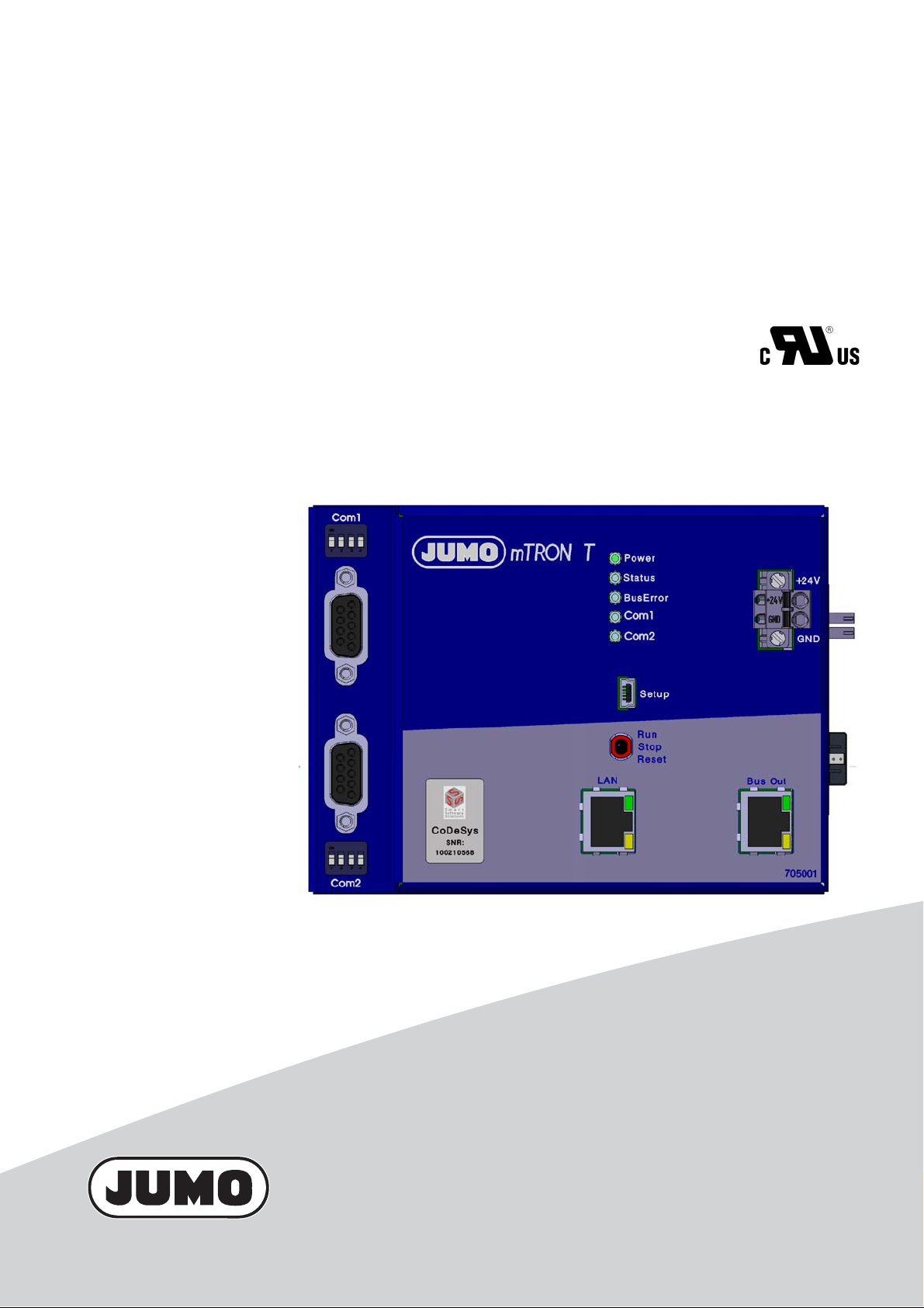
JUMO mTRON T
Measuring, Control, and Automation System
Central Processing Unit
B 705001.0
Operating Manual
2014-08-27/00575582
Page 2

Page 3

Contents
1 Introduction . . . . . . . . . . . . . . . . . . . . . . . . . . . . . . . . . . . . . . . . . . . . . . . . . . . . . .7
1.1 Available technical documentation . . . . . . . . . . . . . . . . . . . . . . . . . . . . . . . . . . . . . . . . . . . . . . . . 7
1.1.1 General information . . . . . . . . . . . . . . . . . . . . . . . . . . . . . . . . . . . . . . . . . . . . . . . . . . . . . . . . . . . . 7
1.1.2 Base units . . . . . . . . . . . . . . . . . . . . . . . . . . . . . . . . . . . . . . . . . . . . . . . . . . . . . . . . . . . . . . . . . . . 7
1.1.3 Input/output modules . . . . . . . . . . . . . . . . . . . . . . . . . . . . . . . . . . . . . . . . . . . . . . . . . . . . . . . . . . . 7
1.1.4 Special modules . . . . . . . . . . . . . . . . . . . . . . . . . . . . . . . . . . . . . . . . . . . . . . . . . . . . . . . . . . . . . . 8
1.1.5 Operating, visualization, recording . . . . . . . . . . . . . . . . . . . . . . . . . . . . . . . . . . . . . . . . . . . . . . . . 8
1.1.6 Power supply units . . . . . . . . . . . . . . . . . . . . . . . . . . . . . . . . . . . . . . . . . . . . . . . . . . . . . . . . . . . . 8
1.2 Safety information . . . . . . . . . . . . . . . . . . . . . . . . . . . . . . . . . . . . . . . . . . . . . . . . . . . . . . . . . . . . . 9
1.2.1 Warning symbols . . . . . . . . . . . . . . . . . . . . . . . . . . . . . . . . . . . . . . . . . . . . . . . . . . . . . . . . . . . . . . 9
1.2.2 Note signs . . . . . . . . . . . . . . . . . . . . . . . . . . . . . . . . . . . . . . . . . . . . . . . . . . . . . . . . . . . . . . . . . . . 9
1.2.3 Intended use . . . . . . . . . . . . . . . . . . . . . . . . . . . . . . . . . . . . . . . . . . . . . . . . . . . . . . . . . . . . . . . . 10
1.2.4 Qualification of personnel . . . . . . . . . . . . . . . . . . . . . . . . . . . . . . . . . . . . . . . . . . . . . . . . . . . . . . 10
1.3 Acceptance of goods, storage, and transport . . . . . . . . . . . . . . . . . . . . . . . . . . . . . . . . . . . . . . . 11
1.3.1 Checking the delivery . . . . . . . . . . . . . . . . . . . . . . . . . . . . . . . . . . . . . . . . . . . . . . . . . . . . . . . . . 11
1.3.2 Notes on storage and transport . . . . . . . . . . . . . . . . . . . . . . . . . . . . . . . . . . . . . . . . . . . . . . . . . . 11
1.3.3 Returning goods . . . . . . . . . . . . . . . . . . . . . . . . . . . . . . . . . . . . . . . . . . . . . . . . . . . . . . . . . . . . . 11
1.3.4 Disposal . . . . . . . . . . . . . . . . . . . . . . . . . . . . . . . . . . . . . . . . . . . . . . . . . . . . . . . . . . . . . . . . . . . . 12
1.4 Identifying the device version . . . . . . . . . . . . . . . . . . . . . . . . . . . . . . . . . . . . . . . . . . . . . . . . . . . 13
1.4.1 Nameplate . . . . . . . . . . . . . . . . . . . . . . . . . . . . . . . . . . . . . . . . . . . . . . . . . . . . . . . . . . . . . . . . . . 13
1.4.2 Order details . . . . . . . . . . . . . . . . . . . . . . . . . . . . . . . . . . . . . . . . . . . . . . . . . . . . . . . . . . . . . . . . 14
1.4.3 Delivery package . . . . . . . . . . . . . . . . . . . . . . . . . . . . . . . . . . . . . . . . . . . . . . . . . . . . . . . . . . . . . 15
1.4.4 Accessories . . . . . . . . . . . . . . . . . . . . . . . . . . . . . . . . . . . . . . . . . . . . . . . . . . . . . . . . . . . . . . . . . 15
1.4.5 General accessories . . . . . . . . . . . . . . . . . . . . . . . . . . . . . . . . . . . . . . . . . . . . . . . . . . . . . . . . . . 16
1.5 System version . . . . . . . . . . . . . . . . . . . . . . . . . . . . . . . . . . . . . . . . . . . . . . . . . . . . . . . . . . . . . . 16
2 Description . . . . . . . . . . . . . . . . . . . . . . . . . . . . . . . . . . . . . . . . . . . . . . . . . . . . . .17
2.1 Brief description . . . . . . . . . . . . . . . . . . . . . . . . . . . . . . . . . . . . . . . . . . . . . . . . . . . . . . . . . . . . . . 17
2.2 Block diagram . . . . . . . . . . . . . . . . . . . . . . . . . . . . . . . . . . . . . . . . . . . . . . . . . . . . . . . . . . . . . . . 17
3 Installation . . . . . . . . . . . . . . . . . . . . . . . . . . . . . . . . . . . . . . . . . . . . . . . . . . . . . .19
3.1 General information on installation/dismounting . . . . . . . . . . . . . . . . . . . . . . . . . . . . . . . . . . . . . 19
3.2 Installation/dismounting on DIN rail . . . . . . . . . . . . . . . . . . . . . . . . . . . . . . . . . . . . . . . . . . . . . . . 20
3.2.1 Base units . . . . . . . . . . . . . . . . . . . . . . . . . . . . . . . . . . . . . . . . . . . . . . . . . . . . . . . . . . . . . . . . . . 21
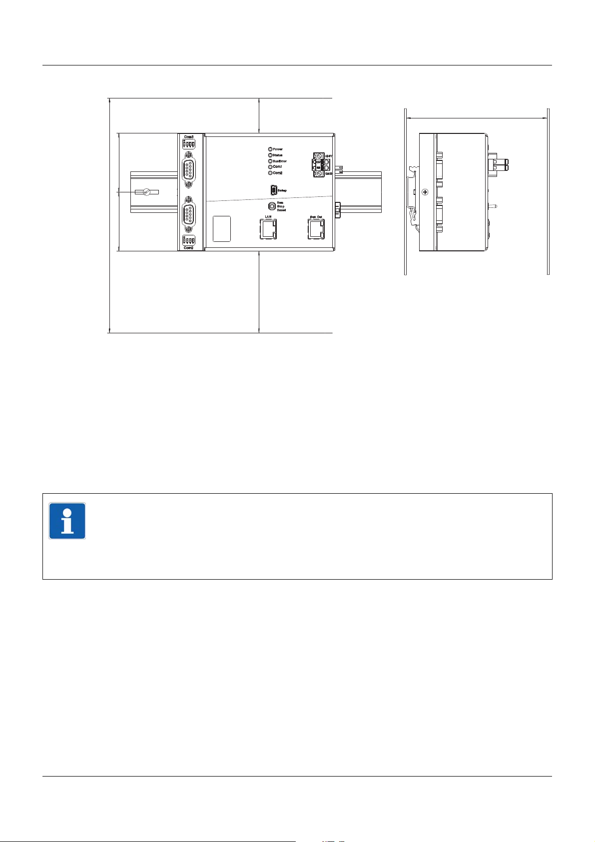
3.3 Dimensions . . . . . . . . . . . . . . . . . . . . . . . . . . . . . . . . . . . . . . . . . . . . . . . . . . . . . . . . . . . . . . . . . 24
4 Electrical connection . . . . . . . . . . . . . . . . . . . . . . . . . . . . . . . . . . . . . . . . . . . . .25
4.1 Installation notes . . . . . . . . . . . . . . . . . . . . . . . . . . . . . . . . . . . . . . . . . . . . . . . . . . . . . . . . . . . . . 25
4.2 Electrical isolation . . . . . . . . . . . . . . . . . . . . . . . . . . . . . . . . . . . . . . . . . . . . . . . . . . . . . . . . . . . . 26
4.3 Connection diagram . . . . . . . . . . . . . . . . . . . . . . . . . . . . . . . . . . . . . . . . . . . . . . . . . . . . . . . . . . 27
4.3.1 Display, operating, and connection elements . . . . . . . . . . . . . . . . . . . . . . . . . . . . . . . . . . . . . . . 27
4.3.2 Interfaces . . . . . . . . . . . . . . . . . . . . . . . . . . . . . . . . . . . . . . . . . . . . . . . . . . . . . . . . . . . . . . . . . . . 28
4.3.3 Voltage supply . . . . . . . . . . . . . . . . . . . . . . . . . . . . . . . . . . . . . . . . . . . . . . . . . . . . . . . . . . . . . . . 28
3
Page 4

Contents
4.3.4 Terminating resistors . . . . . . . . . . . . . . . . . . . . . . . . . . . . . . . . . . . . . . . . . . . . . . . . . . . . . . . . . . 29
4.4 Functional check . . . . . . . . . . . . . . . . . . . . . . . . . . . . . . . . . . . . . . . . . . . . . . . . . . . . . . . . . . . . . 30
5 Operation . . . . . . . . . . . . . . . . . . . . . . . . . . . . . . . . . . . . . . . . . . . . . . . . . . . . . . .33
5.1 Display, operating, and connection elements . . . . . . . . . . . . . . . . . . . . . . . . . . . . . . . . . . . . . . . 33
5.2 System states . . . . . . . . . . . . . . . . . . . . . . . . . . . . . . . . . . . . . . . . . . . . . . . . . . . . . . . . . . . . . . . 34
5.3 System switch . . . . . . . . . . . . . . . . . . . . . . . . . . . . . . . . . . . . . . . . . . . . . . . . . . . . . . . . . . . . . . . 35
5.4 LED displays . . . . . . . . . . . . . . . . . . . . . . . . . . . . . . . . . . . . . . . . . . . . . . . . . . . . . . . . . . . . . . . . 38
5.4.1 Display modes . . . . . . . . . . . . . . . . . . . . . . . . . . . . . . . . . . . . . . . . . . . . . . . . . . . . . . . . . . . . . . . 39
5.4.2 System states and errors . . . . . . . . . . . . . . . . . . . . . . . . . . . . . . . . . . . . . . . . . . . . . . . . . . . . . . 40
5.5 Operation on the multifunction panel . . . . . . . . . . . . . . . . . . . . . . . . . . . . . . . . . . . . . . . . . . . . . . 43
5.5.1 Program generator . . . . . . . . . . . . . . . . . . . . . . . . . . . . . . . . . . . . . . . . . . . . . . . . . . . . . . . . . . . 44
6 Configuration . . . . . . . . . . . . . . . . . . . . . . . . . . . . . . . . . . . . . . . . . . . . . . . . . . . .51
6.1 Selectors . . . . . . . . . . . . . . . . . . . . . . . . . . . . . . . . . . . . . . . . . . . . . . . . . . . . . . . . . . . . . . . . . . . 51
6.1.1 Analog selector . . . . . . . . . . . . . . . . . . . . . . . . . . . . . . . . . . . . . . . . . . . . . . . . . . . . . . . . . . . . . . 51
6.1.2 Digital selector . . . . . . . . . . . . . . . . . . . . . . . . . . . . . . . . . . . . . . . . . . . . . . . . . . . . . . . . . . . . . . . 53
6.2 Device data . . . . . . . . . . . . . . . . . . . . . . . . . . . . . . . . . . . . . . . . . . . . . . . . . . . . . . . . . . . . . . . . . 58
6.2.1 Setup info . . . . . . . . . . . . . . . . . . . . . . . . . . . . . . . . . . . . . . . . . . . . . . . . . . . . . . . . . . . . . . . . . . 59
6.3 Variables . . . . . . . . . . . . . . . . . . . . . . . . . . . . . . . . . . . . . . . . . . . . . . . . . . . . . . . . . . . . . . . . . . . 60
6.3.1 Analog variables . . . . . . . . . . . . . . . . . . . . . . . . . . . . . . . . . . . . . . . . . . . . . . . . . . . . . . . . . . . . . 60
6.3.2 Integer variables . . . . . . . . . . . . . . . . . . . . . . . . . . . . . . . . . . . . . . . . . . . . . . . . . . . . . . . . . . . . . 62
6.3.3 Digital variables . . . . . . . . . . . . . . . . . . . . . . . . . . . . . . . . . . . . . . . . . . . . . . . . . . . . . . . . . . . . . . 65
6.3.4 Text variables . . . . . . . . . . . . . . . . . . . . . . . . . . . . . . . . . . . . . . . . . . . . . . . . . . . . . . . . . . . . . . . 67
6.4 Limit value monitoring . . . . . . . . . . . . . . . . . . . . . . . . . . . . . . . . . . . . . . . . . . . . . . . . . . . . . . . . . 68
6.4.1 Alarm . . . . . . . . . . . . . . . . . . . . . . . . . . . . . . . . . . . . . . . . . . . . . . . . . . . . . . . . . . . . . . . . . . . . . . 72
6.4.2 Alarm and hysteresis functions . . . . . . . . . . . . . . . . . . . . . . . . . . . . . . . . . . . . . . . . . . . . . . . . . . 73
6.5 Binary links . . . . . . . . . . . . . . . . . . . . . . . . . . . . . . . . . . . . . . . . . . . . . . . . . . . . . . . . . . . . . . . . . 75
6.6 Modbus/TCP . . . . . . . . . . . . . . . . . . . . . . . . . . . . . . . . . . . . . . . . . . . . . . . . . . . . . . . . . . . . . . . . 76
6.7 Serial interface . . . . . . . . . . . . . . . . . . . . . . . . . . . . . . . . . . . . . . . . . . . . . . . . . . . . . . . . . . . . . . 78
6.7.1 Modem . . . . . . . . . . . . . . . . . . . . . . . . . . . . . . . . . . . . . . . . . . . . . . . . . . . . . . . . . . . . . . . . . . . . 80
6.8 PROFIBUS (version 02) . . . . . . . . . . . . . . . . . . . . . . . . . . . . . . . . . . . . . . . . . . . . . . . . . . . . . . . 83
6.9 Web server . . . . . . . . . . . . . . . . . . . . . . . . . . . . . . . . . . . . . . . . . . . . . . . . . . . . . . . . . . . . . . . . . 85
6.10 PLC configuration . . . . . . . . . . . . . . . . . . . . . . . . . . . . . . . . . . . . . . . . . . . . . . . . . . . . . . . . . . . . 87
6.11 Program generator . . . . . . . . . . . . . . . . . . . . . . . . . . . . . . . . . . . . . . . . . . . . . . . . . . . . . . . . . . . 89
6.11.1 General . . . . . . . . . . . . . . . . . . . . . . . . . . . . . . . . . . . . . . . . . . . . . . . . . . . . . . . . . . . . . . . . . . . . 90
6.11.2 Setpoint limits . . . . . . . . . . . . . . . . . . . . . . . . . . . . . . . . . . . . . . . . . . . . . . . . . . . . . . . . . . . . . . . 93
6.11.3 Basic status setpoints . . . . . . . . . . . . . . . . . . . . . . . . . . . . . . . . . . . . . . . . . . . . . . . . . . . . . . . . . 95
6.11.4 Manual mode setpoints . . . . . . . . . . . . . . . . . . . . . . . . . . . . . . . . . . . . . . . . . . . . . . . . . . . . . . . . 96
6.11.5 Setpoint specification . . . . . . . . . . . . . . . . . . . . . . . . . . . . . . . . . . . . . . . . . . . . . . . . . . . . . . . . . 97
6.11.6 Names of operating contacts . . . . . . . . . . . . . . . . . . . . . . . . . . . . . . . . . . . . . . . . . . . . . . . . . . . . 98
6.11.7 Tolerance band monitoring . . . . . . . . . . . . . . . . . . . . . . . . . . . . . . . . . . . . . . . . . . . . . . . . . . . . . 99
6.11.8 Events . . . . . . . . . . . . . . . . . . . . . . . . . . . . . . . . . . . . . . . . . . . . . . . . . . . . . . . . . . . . . . . . . . . . 101
6.11.9 Process screen . . . . . . . . . . . . . . . . . . . . . . . . . . . . . . . . . . . . . . . . . . . . . . . . . . . . . . . . . . . . . 103
4
Page 5

Contents
7 Parameterization . . . . . . . . . . . . . . . . . . . . . . . . . . . . . . . . . . . . . . . . . . . . . . . .107
7.1 PLC parameter . . . . . . . . . . . . . . . . . . . . . . . . . . . . . . . . . . . . . . . . . . . . . . . . . . . . . . . . . . . . . 107
8 Configuration – in setup program only . . . . . . . . . . . . . . . . . . . . . . . . . . . . . .111
8.1 E-mail . . . . . . . . . . . . . . . . . . . . . . . . . . . . . . . . . . . . . . . . . . . . . . . . . . . . . . . . . . . . . . . . . . . . 111
8.1.1 E-mail server . . . . . . . . . . . . . . . . . . . . . . . . . . . . . . . . . . . . . . . . . . . . . . . . . . . . . . . . . . . . . . . 113
8.2 Modbus frames for reading . . . . . . . . . . . . . . . . . . . . . . . . . . . . . . . . . . . . . . . . . . . . . . . . . . . . 114
8.3 Modbus frames for writing . . . . . . . . . . . . . . . . . . . . . . . . . . . . . . . . . . . . . . . . . . . . . . . . . . . . . 115
8.4 Analog PLC output texts . . . . . . . . . . . . . . . . . . . . . . . . . . . . . . . . . . . . . . . . . . . . . . . . . . . . . . 116
8.5 Integer PLC output texts . . . . . . . . . . . . . . . . . . . . . . . . . . . . . . . . . . . . . . . . . . . . . . . . . . . . . . 117
8.6 Digital PLC output texts . . . . . . . . . . . . . . . . . . . . . . . . . . . . . . . . . . . . . . . . . . . . . . . . . . . . . . . 118
8.7 Texts . . . . . . . . . . . . . . . . . . . . . . . . . . . . . . . . . . . . . . . . . . . . . . . . . . . . . . . . . . . . . . . . . . . . . 119
9 Program editor . . . . . . . . . . . . . . . . . . . . . . . . . . . . . . . . . . . . . . . . . . . . . . . . . .121
9.1 General information . . . . . . . . . . . . . . . . . . . . . . . . . . . . . . . . . . . . . . . . . . . . . . . . . . . . . . . . . . 121
9.2 Program schema . . . . . . . . . . . . . . . . . . . . . . . . . . . . . . . . . . . . . . . . . . . . . . . . . . . . . . . . . . . . 122
9.3 Program simulation . . . . . . . . . . . . . . . . . . . . . . . . . . . . . . . . . . . . . . . . . . . . . . . . . . . . . . . . . . 127
9.4 Process steps (as of version 02) . . . . . . . . . . . . . . . . . . . . . . . . . . . . . . . . . . . . . . . . . . . . . . . . 130
9.5 License dependance . . . . . . . . . . . . . . . . . . . . . . . . . . . . . . . . . . . . . . . . . . . . . . . . . . . . . . . . . 132
9.5.1 "Program editor" license . . . . . . . . . . . . . . . . . . . . . . . . . . . . . . . . . . . . . . . . . . . . . . . . . . . . . . 132
10 Online parameters . . . . . . . . . . . . . . . . . . . . . . . . . . . . . . . . . . . . . . . . . . . . . . .133
10.1 Ethernet . . . . . . . . . . . . . . . . . . . . . . . . . . . . . . . . . . . . . . . . . . . . . . . . . . . . . . . . . . . . . . . . . . . 133
10.2 System bus . . . . . . . . . . . . . . . . . . . . . . . . . . . . . . . . . . . . . . . . . . . . . . . . . . . . . . . . . . . . . . . . 136
10.3 Enabling of extra codes . . . . . . . . . . . . . . . . . . . . . . . . . . . . . . . . . . . . . . . . . . . . . . . . . . . . . . . 137
10.4 Resetting the user list . . . . . . . . . . . . . . . . . . . . . . . . . . . . . . . . . . . . . . . . . . . . . . . . . . . . . . . . 138
10.5 Date and time . . . . . . . . . . . . . . . . . . . . . . . . . . . . . . . . . . . . . . . . . . . . . . . . . . . . . . . . . . . . . . 139
10.6 Calibrate / test . . . . . . . . . . . . . . . . . . . . . . . . . . . . . . . . . . . . . . . . . . . . . . . . . . . . . . . . . . . . . . 140
10.6.1 LED test . . . . . . . . . . . . . . . . . . . . . . . . . . . . . . . . . . . . . . . . . . . . . . . . . . . . . . . . . . . . . . . . . . . 140
10.6.2 Switch test . . . . . . . . . . . . . . . . . . . . . . . . . . . . . . . . . . . . . . . . . . . . . . . . . . . . . . . . . . . . . . . . . 141
10.6.3 Versions . . . . . . . . . . . . . . . . . . . . . . . . . . . . . . . . . . . . . . . . . . . . . . . . . . . . . . . . . . . . . . . . . . 142
10.6.4 Battery . . . . . . . . . . . . . . . . . . . . . . . . . . . . . . . . . . . . . . . . . . . . . . . . . . . . . . . . . . . . . . . . . . . . 142
11 Retrofitting interfaces . . . . . . . . . . . . . . . . . . . . . . . . . . . . . . . . . . . . . . . . . . . .143
12 Appendix . . . . . . . . . . . . . . . . . . . . . . . . . . . . . . . . . . . . . . . . . . . . . . . . . . . . . .147
12.1 Technical data . . . . . . . . . . . . . . . . . . . . . . . . . . . . . . . . . . . . . . . . . . . . . . . . . . . . . . . . . . . . . . 147
12.1.1 Interfaces . . . . . . . . . . . . . . . . . . . . . . . . . . . . . . . . . . . . . . . . . . . . . . . . . . . . . . . . . . . . . . . . . . 147
12.1.2 Electrical data . . . . . . . . . . . . . . . . . . . . . . . . . . . . . . . . . . . . . . . . . . . . . . . . . . . . . . . . . . . . . . 147
12.1.3 Case and ambient conditions . . . . . . . . . . . . . . . . . . . . . . . . . . . . . . . . . . . . . . . . . . . . . . . . . . 148
12.1.4 Approval/approval marks . . . . . . . . . . . . . . . . . . . . . . . . . . . . . . . . . . . . . . . . . . . . . . . . . . . . . . 148
12.2 Cycle time, sampling rate, and shut-down time . . . . . . . . . . . . . . . . . . . . . . . . . . . . . . . . . . . . . 149
5
Page 6

Contents
12.3 Resources for customer specific PLC programs . . . . . . . . . . . . . . . . . . . . . . . . . . . . . . . . . . . . 150
6
Page 7

1.1 Available technical documentation
The documents specified below are available for the measuring, control, and automation system.
1.1.1 General information
Product Type of documentation No. Printed PDF file
Measuring,
control, and
automation system
1
Accessory subject to charge
2
Includes an overview of the purpose and content of all documents
1.1.2 Base units
Data sheet T 705000 - X
System manual
Setup program manual B 705000.6 - X
System description
1
2
1 Introduction
B 705000.0 X -
B 705000.8 - X
Product Type of documentation No. Printed PDF file
Central
processing unit
Data sheet T 705001 - X
Operating manual B 705001.0 - X
Modbus interface description B 705001.2.0 - X
Installation instructions B 705001.4 X X
1.1.3 Input/output modules
Product Type of documentation No. Printed PDF file
Multichannel
controller module
Relay module
4-channel
Analog
input module
4-channel
Data sheet T 705010 - X
Operating manual B 705010.0 - X
Installation instructions X X
Data sheet T 705015 - X
Operating manual B 705015.0 - X
Installation instructions B 705015.4 X X
Data sheet T 705020 - X
Operating manual B 705020.0 - X
Installation instructions B 705020.4 X X
Analog
input module
8-channel
Digital input/
output module
12-channel
Data sheet T 705021 - X
Operating manual B 705021.0 - X
Installation instructions B 705021.4 X X
Data sheet T 705030 - X
Operating manual B 705030.0 - X
Installation instructions B 705030.4 X X
7
Page 8

1 Introduction
1.1.4 Special modules
Product Type of documentation No. Printed PDF file
Router module Data sheet T 705040 - X
Installation instructions B 705040.4 X X
1.1.5 Operating, visualization, recording
Product Type of documentation No. Printed PDF file
Multifunction
panel 840
Operating panels Data sheet T 705065 - X
Data sheet T 705060 - X
Operating manual B 705060.0 - X
Modbus interface description B 705060.2.0 - X
Installation instructions B 705060.4 X X
1.1.6 Power supply units
Product Type of documentation No. Printed PDF file
24 V power supply
units
Data sheet T 705090 - X
Operating instructions QS5.241 X Operating instructions QS10.241 X -
8
Page 9
1.2 Safety information
&
1.2.1 Warning symbols
DANGER!
This symbol indicates that personal injury caused by electrical shock may occur if the respective precautionary measures are not carried out.
WARNING!
This symbol in connection with the signal word indicates that personal injury may occur if the
respective precautionary measures are not carried out.
CAUTION!
This symbol in connection with the signal word indicates that damage to assets or data loss
will occur if the respective precautionary measures are not taken.
CAUTION!
This symbol indicates that components could be destroyed by electrostatic discharge
(ESD = Electro Static Discharge) if the respective cautionary measures are not taken.
Only use the ESD packages intended for this purpose to return device inserts, assembly
groups, or assembly components.
1 Introduction
READ DOCUMENTATION!
This symbol – placed on the device – indicates that the associated device documentation
has to be observed. This is necessary to recognize the kind of the potential hazards as
well as the measures to avoid them.
1.2.2 Note signs
NOTE!
This symbol refers to important information about the product, its handling, or additional
use.
REFERENCE!
This symbol refers to further information in other sections, chapters, or manuals.
FURTHER INFORMATION!
This symbol is used in the tables and refers to further information in connection with the
table.
DISPOSAL!
This device and the batteries (if installed) must not be disposed in the garbage can after
use! Please ensure that they are disposed properly and in an environmentally friendly
manner.
9
Page 10

1 Introduction
1.2.3 Intended use
The modules described are intended for measuring, control, an d automation t asks in an ind ustrial environment, as described in the technical data. Oth er uses or uses beyond th ose defined
are not viewed as intended uses.
The modules are built according to the relevant standards and directives as well as the applicable safety regulations. Nevertheless, incorrect use may lead to bodily injury or property damage.
To avoid danger, the modules may only be used:
• For the intended use
• When in good order and condition
• When taking into account the technical documentation provided
Even if a module is used correctly and according to the intended use, it may still cause appli-
cation-related dangers (e.g. due to missing safety devices or incorrect settings).
1.2.4 Qualification of personnel
This document contains the necessary information for the intended use of the modules to which
it relates.
It is intended for technically qualified personnel who have received special training and have
the appropriate knowledge in the field of automation technology (measuring, process, and control technology).
The appropriate level of knowledge and the technically fault-free implementation of the safety
information and warnings contained in the technical documentation provided are prerequisites
for risk-free mounting, installation, and startup as well as for ensuring safety when operating
the described modules. Only qualified personnel have the required specialist knowledge to correctly interpret and implement the safety information and warnings contained in this document
in specific situations.
10
Page 11

1.3 Acceptance of goods, storage, and transport
1.3.1 Checking the delivery
• Ensure that the packaging and contents are not damaged
• Check that the delivery is complete using the delivery papers and the order details
• Inform the supplier immediately if there is any damage
• Store damaged parts until clarification is received from the supplier
1.3.2 Notes on storage and transport
• Store the module in a dry and clean environment. Observe the admissible ambient conditions (see "Technical data")
• The transport of the module is to be shockproof
• The original packaging provides optimum protection for storage and transport
1.3.3 Returning goods
In the event of repair, please return the module in a clean and complete state.
Use the original packaging to return goods.
1 Introduction
Accompanying letter for repair
Please include the completed accompanying letter for repair when returning goods.
Do not forget to state the following:
• Description of the application and
• Description of the error that has occurred
The accompanying letter for repair can be downloaded online from the manufacturer's website
(use the search function if necessary).
Protection against electrostatic discharge (ESD)
(ESD = electrostatic discharge)
To prevent damage from ESD, electronic modules or components must be handled, packaged,
and stored in an ESD-protected environment. Measures against electrostatic discharge and
electrical fields are described in DIN EN 61340-5-1 and DIN EN 6 1340-5-2 "Protection of electronic devices from electrostatic phenomena".
When returning electronic modules or components, please note the following:
• Sensitive components must only be packaged in an ESD-protected environment. Workspaces such as this divert electrostatic charges to ground in a controlled manner and prevent static charges due to friction capacities.
• Only use packaging for ESD-sensitive modules/components. These must consist of conductive plastics.
No liability can be assumed for damage caused by ESD.
11
Page 12

1 Introduction
CAUTION!
Electrostatic charges occur in non-ESD protected environments.
Electrostatic discharges can damage modules or components.
For transport purposes, use only the ESD packaging provided.
1.3.4 Disposal
Disposing of the device
DISPOSAL!
Devices and/or replaced parts should not be placed in the refuse bin at the end of their service life as they consist of materials that can be recycled by specialist recycling plants.
Dispose of the device and the packaging material in a proper and environmentally friendly
manner.
For this purpose, observe the country-specific laws and regulations for waste treatment a nd
disposal.
Disposing of the packaging material
The entire packaging material (cardboard packaging, inserts, plastic film, and plastic bags) is
fully recyclable.
12
Page 13
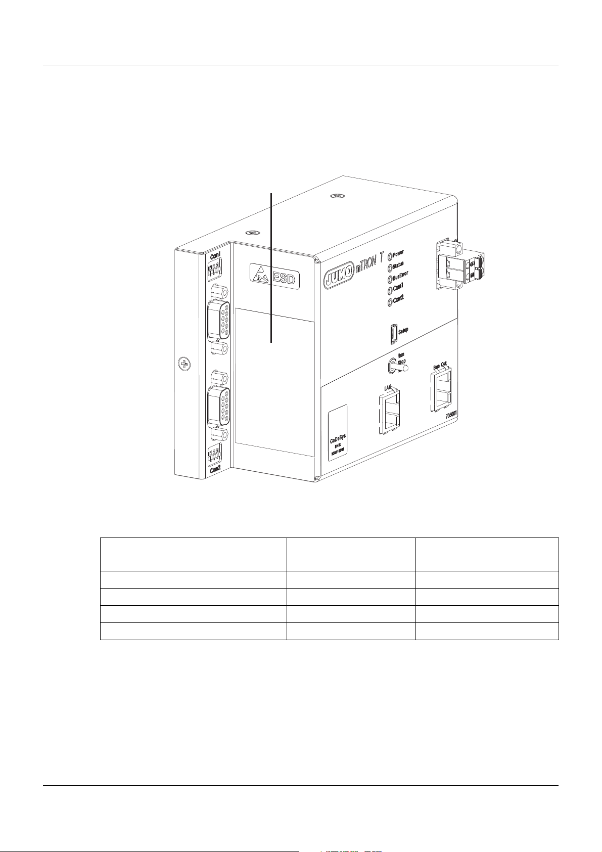
1.4 Identifying the device version
(A)
1.4.1 Nameplate
Position
The nameplate (A) is affixed to the module case.
1 Introduction
Contents
It contains important information. This includes:
Device type
Compare the specifications on the nameplate with the order.
Identify the supplied device version using the order details of the respective module.
Part no. (TN)
The part no. clearly identifies an article in the catalog. It is important for communication
between the customer and the sales department.
Description Designation on the name-
plate
Device type Type 705001/08-51-54-36/000
Part no. TN 00XXXXXX
Fabrication number F-Nr 0070033801211010006
Voltage supply - DC 24 V -20/+25 %
Example
13
Page 14

1 Introduction
Fabrication no. (F-Nr)
Among other things, the fabrication number contains the date of production (year/week).
Example: F-Nr = 0070033801211010006
The figures concerned are in positions 12, 13, 14, and 15 (from the left).
The device was therefore produced in the 1st calendar week of 2011.
1.4.2 Order details
(1) Basic type
705001 Central processing unit (1x Ethernet (RJ45), 1x system bus (RJ45), 1x system bus (E-
Bus), monitoring of 64 limit values)
(2) Basic type extension
0 Standard
(3) Version
8 With factory settings
(4) Interface Com1
00 Not used
51 RS232 Modbus RTU
54 RS422/485 Modbus RTU
(5) Interface Com2
00 Not used
51 RS232 Modbus RTU
54 RS422/485 Modbus RTU
64 PROFIBUS-DP (slave; as of system version 02)
(6) Voltage supply
36 DC 24 V +25/-20 %
(7) Extra codes
000 Without extra code
214 Math/logic function (activation for all connected controller modules)
224 PLC acc. to IEC 61131-3 (CODESYS V3)
225 Program generator 1 to 9
228 Program generator 1 to 9 with process steps (as of system version 02)
14
(1) (2) (3) (4) (5) (6) (7)
Order code /---/,...
Order example 705001 / 0 8 - 00 - 00 - 36 / 214
1
List extra codes in sequence, separated by a comma.
1
Page 15

1.4.3 Delivery package
1 central processing unit in the ordered version
1 cover for system bus
2 screw-on end clamps for DIN rail
1 Installation Instructions B 705001.4
Setup program with program editor JUMO mTRON T (30-day trial version, on MiniDVD)
Content of the Mini-DVD:
• Setup program with program editor JUMO mTRON T (30-day trial version)
• CODESYS programming software (free version)
• CODESYS Repository Package - Operating panels (free version)
• GSD file JUMO mTRON T - CPU (free version)
• PC Evaluation Software PCA3000 (30-day trial version)
• PCA Communication Software PCC (30-day trial version)
• Documentation in PDF format
1.4.4 Accessories
1 Introduction
Article Part no.
Interface modules (expansion boards):
RS232 Modbus RTU 00569505
RS422/485 Modbus RTU 00569506
PROFIBUS-DP (slave; as of system version 02 and as of the central processing unit‘s
production date 27/2013 (calendar week))
Extra codes (activations):
Math/logic module (activation for all connected controller modules) 00569509
PLC according to IEC 61131-3 (CODESYS V3) 00569510
Program generator 1 to 9 00569511
Program generator 1 to 9 with process steps (as of system version 02) 00606498
00569507
15
Page 16

1 Introduction
1.4.5 General accessories
Article Part no.
JUMO mTRON T system manual, English 00575577
Setup program with program editor JUMO mTRON T (on MiniDVD), incl. USB cable
(A-plug to mini-B-plug, 3 m)
Program editor JUMO mTRON T (on MiniDVD), incl. USB cable (A-plug to mini-B-
plug, 3 m)
PCA3000/PCC JUMO software package 00431884
PC Evaluation Software PCA3000 00431882
Release automatic print for PC Evaluation Software PCA3000 00505548
PCA Communication Software PCC 00431879
Plant Visualization Software JUMO SVS3000: See data sheet 700755 USB cable A-plug mini-B-plug 3 m 00506265
Content of the Mini-DVD:
• Setup program with program editor JUMO mTRON T in case of part no. 00569494
• Program editor JUMO mTRON T in case of part no. 00622333
• CODESYS programming software (free version)
• CODESYS Repository Package - Operating panels (free version)
• GSD file JUMO mTRON T - CPU (free version)
• PC Evaluation Software PCA3000 (30-day trial version)
• PCA Communication Software PCC (30-day trial version)
• Documentation in PDF format
00569494
00622333
1.5 System version
The system version of the measuring, control, and automation system is determined by the
compatibility index of the base unit.
Example composition of a version number for the central processing unit: 248.xx.yy
248 = basic version, xx = compatibility index (system version), yy = current version
In the current document, descriptions that apply only for a particular system version are labeled
accordingly (e.g. "version 02").
16
Page 17
2.1 Brief description
Com1
RS232 (Modbus RTU) or
RS422/485 (Modbus RTU)
705001
Voltage supply Out
System bus
Com2
RS232 (Modbus RTU) or
RS422/485 (Modbus RTU) or
PROFIBUS-DP slave
USB (device)
For setup program
Bus Out
To permit connection to a
multifunction panel or
router module
LAN
Mainly for use of the
integrated web server
or the setup program
Switch / push-button
Run, Stop, or Reset
Voltage supply In
(at the front)
The central processing unit is the heart of the system. It contains the process image of the application and manages the configuration and parameter data of the complete system (except
for the multifunction panel).
For individual control tasks nine program generators (option) are available and 64 limit values
can be monitored.
LEDs are used to indicate applied voltage su pply, the operating status of the PLC, system malfunctions, as well as the communication through interfaces.
A USB device interface (setup), a LAN connection (Ethernet), and two system bus connections
are available as standard. Up to two interfaces can be optionally equipped for fieldbus applica tions.
The central processing unit, the input/output modules connected laterally, and modules integrated by a router are comfortably configured and parameterized with the setup program.
A PLC according to IEC 61131-3 can be released as an option. A switch is available to toggle
the system operating status (Run, Stop, and Reset).
2.2 Block diagram
2 Description
17
Page 18

2 Description
18
Page 19
3 Installation
3.1 General information on installation/dismounting
DANGER!
With multichannel controller module 705010 and relay module 705015, the load circuits from
relay or solid state relay outputs can be operated with a dangerous electrical voltage (e.g.
230 V).
There is a risk of electric shock.
Prior to the installation/dismounting of these modules or the removal of the module insert, the
load circuits are to be disconnected from the voltage and the terminal strips are to be removed from the module. This work must only be performed by qualified personnel.
WARNING!
The modules must never be installed in areas with an explosion hazard.
There is the risk of an explosion.
The entire system must only be used outside of areas with an explosion hazard.
Mounting site
All modules have protection type IP20 and are only intended for use in fireproof con trol cabinets
or switch boxes. The mounting site should be virtually vibration-free. Electromagnetic fields
caused by equipment such as motors or transformers should be avoided.
Multifunction panel 840 has protection type IP67 at the front and is intended for installation in
a panel cut-out. The rear has protection type IP20.
Climatic conditions
The ambient temperature and the relative humidity at the mounting site must correspond to the
technical data. Aggressive gases and vapors have a negative ef fect on the operating life of the
modules. The mounting site must be free from dust, powder, and other suspended matter so
that the cooling slots do not become blocked.
DIN rail
All modules are mounted on a DIN rail according to DIN EN 60715 (35 mm × 7.5 mm × 1 mm).
For reasons of stability, the spacing of the fastening screws for the DIN rail should not exceed
200 mm. The minimum distances for the modules that are specified in the module-specific installation or operating instructions must be observed.
Installation position
The DIN rail should be mounted horizontally so that all modules are arranged vertically. Otherwise the admissible ambient temperature range will be restricted.
Space requirement
The modules require the minimum distances shown in the following figure for the purpose of
installation/dismounting and for future maintenance or replacement. In the event of shorter distances the minimum bending radius of the cables, the performance of the electrical inst allation,
and the clear arrangement of the plant are no longer guaranteed.
19
Page 20
3 Installation
120
201
50.5
30
70
50.5
Minimum distances
3.2 Installation/dismounting on DIN rail
All modules in the system are intended for installation on a DIN rail according to DIN EN 60715
(35 mm × 7.5 mm × 1 mm).
The following must always be installed on the left, at the start of the DIN rail:
• A central processing unit or
• A router module
These modules connect the input/output modules to the voltage supply and the system bus.
NOTE!
To determine the required minimum width of the DIN rail, the widths of the individual modules
are to be added (see technical data of the modules in the respective data sheet or the
module-specific installation instructions).
The widths of the cover (17.5 mm) and both end brackets (each 9.5 mm) should also be
taken into consideration: 17.5 mm + 2 × 9.5 mm = 36.5 mm.
20
Page 21
3 Installation
(A)
(A2)
(A1)
(B)
(B3)
(B4)
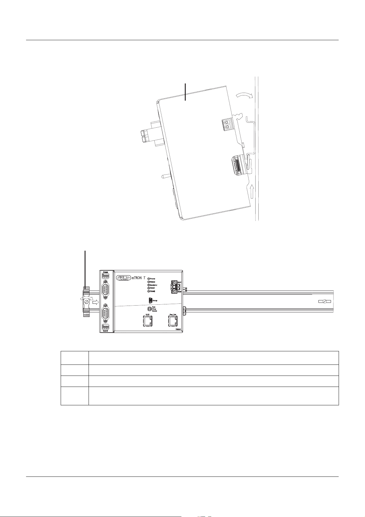
3.2.1 Base units
Installation of a base unit, using the example of a central processing unit 705001
Installing the end brackets
Procedure:
Step Activity
1 Mount the central processing unit (A) on the DIN rail from below and press upward (A1).
2 Pivot the central processing unit (A) toward the rear until it snaps into place (A2).
3 Position the end bracket (B) on the DIN rail and move to the right against the central pro-
cessing unit (B3). Fasten the end bracket using a screwdriver (B4).
21
Page 22
3 Installation
(A) (C) (D)
(C3)
(D2)
(B)
(B4) (B4)
(B)
(A)
(E1)
(E)
(A6)
(A5)
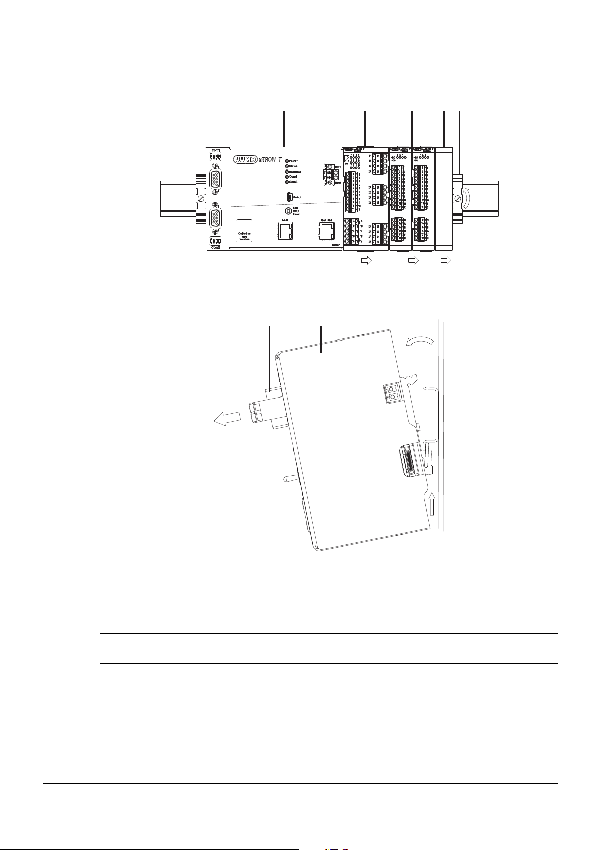
Dismounting a base unit, using the example of a central processing unit 705001
Removing the central processing unit from the DIN rail
22
Procedure:
Step Activity
1 Remove the connection cables if required (Setup, LAN, Bus Out).
2 If required, use a screwdriver to release the wired terminal (E) of the central processing unit
(A) and pull off toward the front (E1).
3 Fully release the end bracket (D) using a screwdriver (D2), press upward from below, pivot
toward the front, and remove from the DIN rail.
Note: The end bracket does not need to be removed from the DIN rail if there is sufficient
space to the side to move it at least 10 mm to the right.
Page 23

3 Installation
Step Activity
4 Move the cover (C) to the right (C3) until the sid e contacts of the neighb or ing mo du le are
exposed. Then release the cover at the bottom using a screwdriver, press upward, and
remove from the DIN rail.
Note: The cover does not need to be removed from the DIN rail if there is sufficient space
to the side to move it at least 10 mm to the right.
5 Move the modules (B) on the right next to the central processing unit (A) to the right (B4)
until the side contacts of the central processing unit are exposed.
➥ These modules are isolated from the voltage supply and the system bus.
6 Press the central processing unit (A) upward from underneath (A5), pivot off the DIN rail
toward the front (A6), and remove.
23
Page 24
3 Installation
6,6
135
101
58.7
67.1
17.4
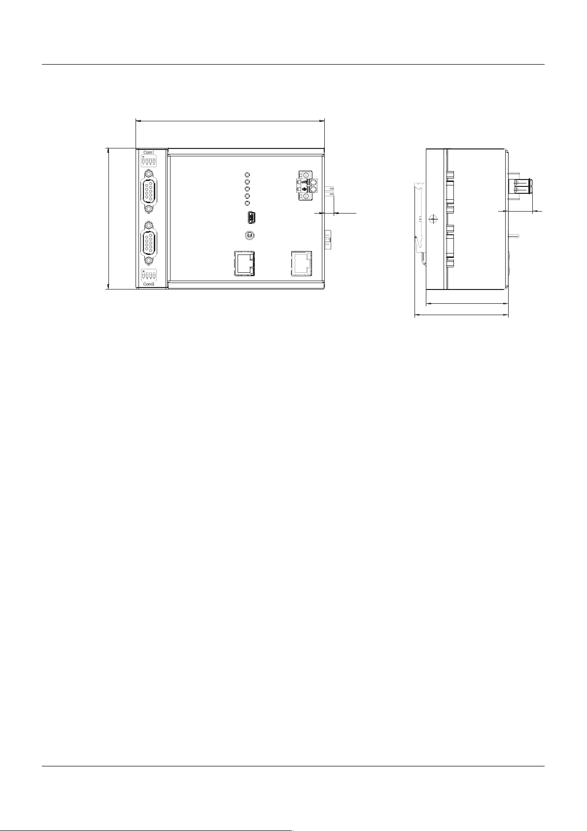
3.3 Dimensions
24
Page 25

4.1 Installation notes
NOTE!
These installation notes apply for the entire measuring, control, and automation system and,
on some occasions, are only applicable for a specific module.
The respective connection diagram shows the context.
Requirements for the personnel
• Work on the modules must only be carried out to the extent described and, like the electrical
connection, only by qualified personnel.
• Before plugging and unplugging connection cables ensure that the person performing the
work is electrostatically discharged (e.g. by touching grounded metallic parts).
Cables, shielding, and grounding
• When selecting the cable material, when installing, and when performing the electrical connection of the module, the regulations of DIN VDE 0100 "Erection of power installations with
rated voltages up to 1000 V" and the respective national regulations (e.g. on the basis of
IEC 60364) are to be observed.
• Certain cables must be heat resistant up to at least 80 °C at maximum load. The relevant
instructions in the connection diagram of the affected modules must be observed.
• Route input, output, and supply cables separately and not parallel to one another.
• Only use shielded and twisted probe and interface cables. Do not route the lines close to
current-carrying components or cables.
• For temperature probes, ground the shielding on one side in the control cabinet.
• Do not perform loopthroughs on the grounding cables, but route the cables individually to a
shared grounding point in the control cabinet; in doing so, ensure that the cables are as
short as possible.
Ensure that the equipotential bonding is correct.
4 Electrical connection
Electrical safety
• Isolate power supply units from the voltage supply on the primary side if there is a risk of
touching parts with dangerous electrical voltage (e.g. 230 V) in the course of work.
• The fuse rating of the power supply units on the primary side should not exceed a value of
10 A (inert).
• With modules with relay or solid state relay outputs, the load circuits can be operated with
a dangerous electrical voltage (e.g. 230 V). Disconnect load circuits from the voltage supply
during installation/dismounting and electrical connection.
• In order to prevent the destruction of the relay or solid state relay outputs in the event of an
external short circuit in the load circuit, the load circuit should be fused to the maximum admissible output current.
• The modules are not suitable for installation in areas with an explosion hazard.
• In addition to a faulty installation, incorrectly set values on the module could also impair the
correct function of the following process. Therefore, ensure that safety devices independent
of the module (e.g. overpressure valves or temperature limiters/monitors) are available and
that it is only possible for qualified personnel to define settings. Please observe the corresponding safety regulations in this context.
25
Page 26
4 Electrical connection
Interface Com1
System bus Out
Side system bus Out
DC 1500 V
USB device interface
(setup)
Interface Com2
LAN
DC 1500 V
AC 30 V
DC 50 V
AC 30 V
DC 50 V
Voltage supply Out
Voltage supply In
References to other information
• The electromagnetic compatibility meets the standards and regulations cited in the technical data.
• The USB device interface and voltage supply in the central processing unit 705001 are not
electrically isolated. In general, please observe the specifications regarding electrical isolation.
4.2 Electrical isolation
26
Page 27
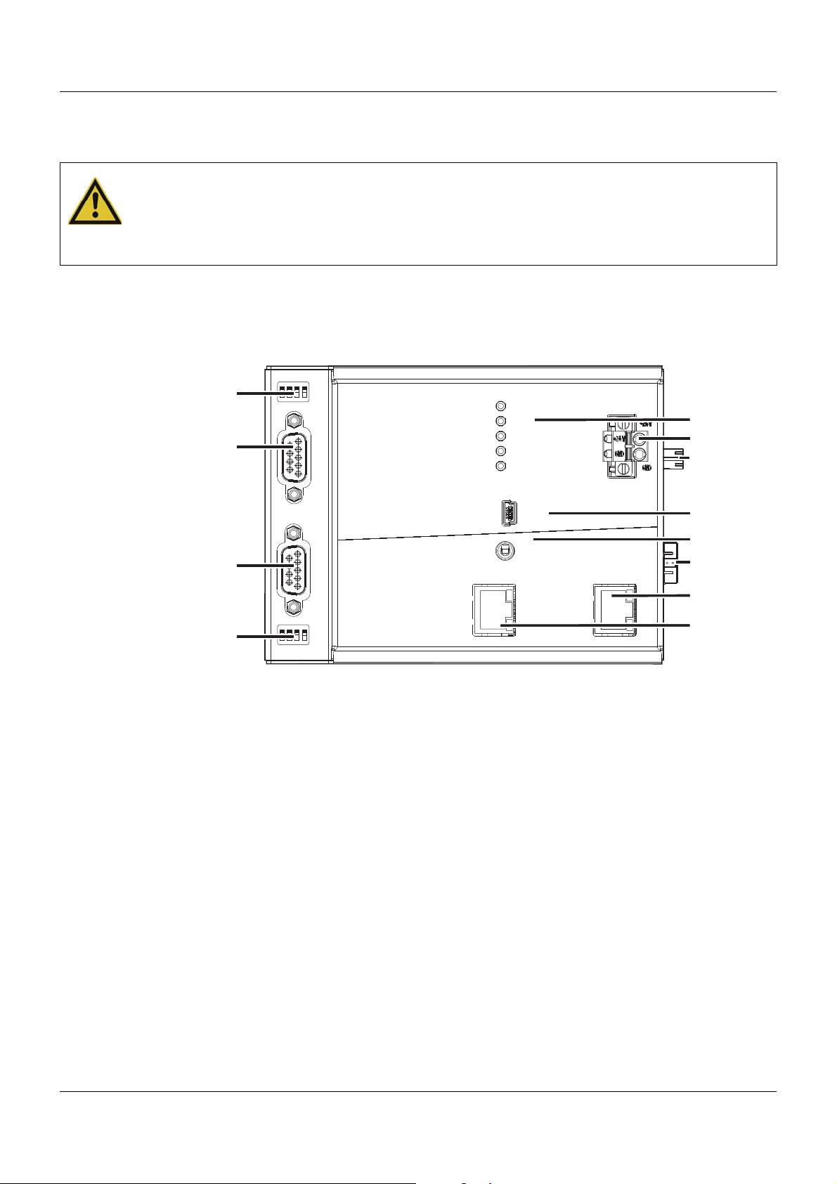
4 Electrical connection
Setup
LAN Bus Out
Run
Stop
Reset
Power
Status
Bus Error
Com1
Com2
Com2
2
1
3
4
ON
2
1
3
4
ON
Com1
(1)
(2)
(3)
(4)
(11)
(5)
(7)
(8)
(10)
(6)
(9)
(12)
4.3 Connection diagram
CAUTION!
At maximum load, the temperature at the "+24 V" and "GND" terminals (Voltage supply In)
may exceed 60 °C.
As a result the insulation of the cable may be damaged.
The cable must be heat resistant up to at least 80 °C.
4.3.1 Display, operating, and connection elements
This overview shows the position of the display, operating, and connection elements. The assignment to individual functions is illustrated in the following sections.
(1) Status displays (LED)
(2) Voltage supply In, DC 24 V
(3) Vo ltage supply Out, DC 24 V
(4) USB device interface (Setup)
(5) Switch/button for Run, Stop, or Reset
(6) Side system bus Out
(7) System bus Out
(8) LAN interface
(9) Com2 terminating resistors
(10) Com2 interface
(1 1) Com1 interface
(12) Com1 terminating resistors
27
Page 28
4 Electrical connection
8
1
8
1
6
7
8
9
2
3
4
5
1
U
+
-
x
4.3.2 Interfaces
Connection Designa-
tion
Number
Connection element
USB device Setup (4)
System bus Out Bus Out (7) 1 TX+
2 TX3 RX+
6 RX-
Ethernet LAN (8) 1 TX+
2 TX3 RX+
6 RX-
Serial interface
(RS232), option
Com1,
Com2
(11),
(10)
2 RxD
3 TxD
5 GND
Serial interface
(RS422), option
Com1,
Com2
(11),
(10)
3 TxD+
4 RxD+
5 GND
8 TxD9 RxD-
Serial interface
(RS485), option
Com1,
Com2
(11),
(10)
3 TxD+/RxD+
5 GND
8 TxD-/RxD-
Transmit data +
Transmit data Receive data +
Receive data -
Transmit data +
Transmit data Receive data +
Receive data Receive data
Transmit data
Ground
Transmit data +
Receive data +
Ground
Transmit data Receive data Transmit/Receive data +
Ground
Transmit/Receive data -
PROFIBUS-DP,
option (as of system version 02)
Com2 (10) 8 RxD/TxD-N (A)
3 RxD/TxD-P (B)
6 VP (+5 V)
5 DGND
Transmit/Receive data Transmit/Receive data +
Voltage supply +
Data ground
4.3.3 Voltage supply
Connection Designation Num-
ber
Voltage supply In +24 V and
(2) +24 V
GND
28
Symbol and terminal designation
GND
Page 29
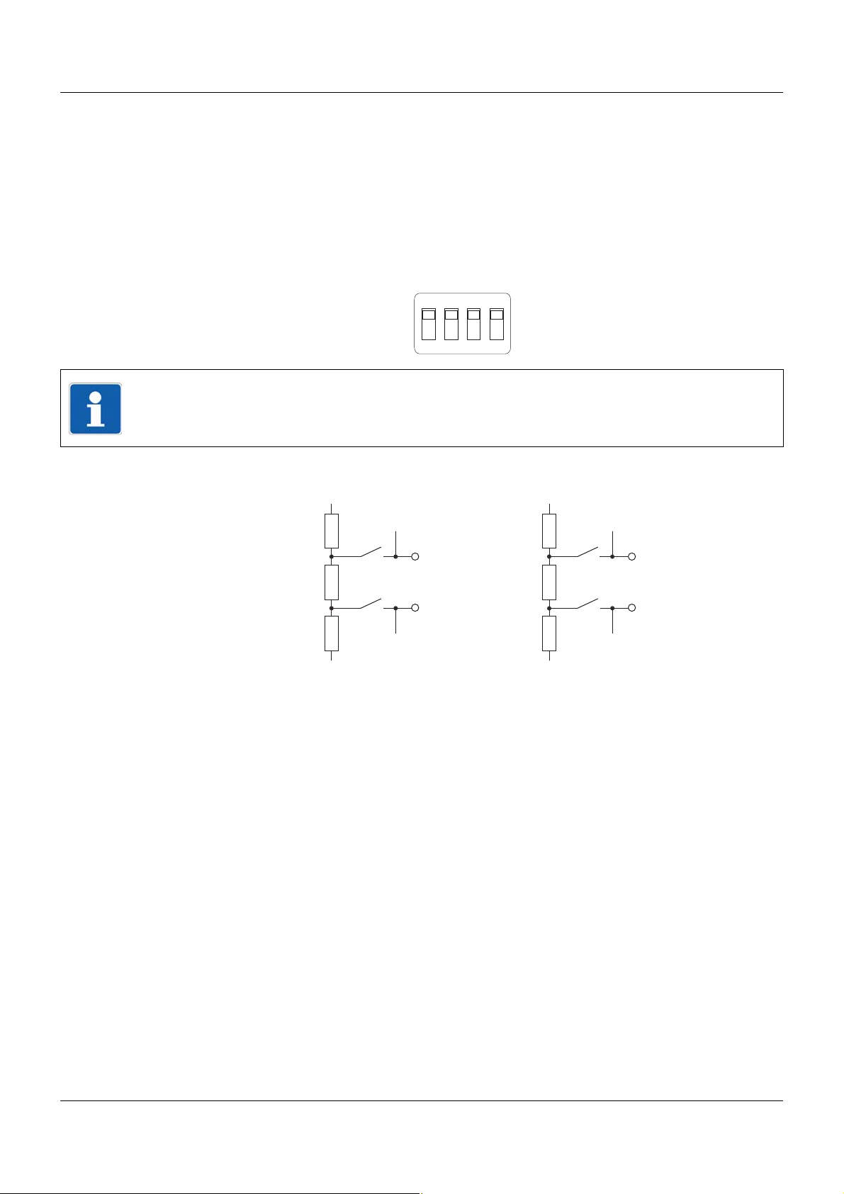
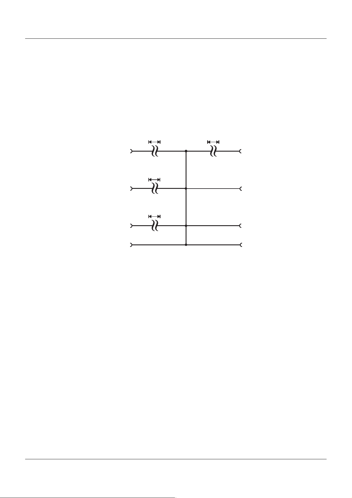
4.3.4 Terminating resistors
2
1
3
4
ON
332 ?
120 ?
332 ?
GND
+5 V
4
9
332 ?
120 ?
332 ?
GND
+5 V
3
4
3
8
1
2
The internal terminating resistors for the Com1 and Com2 interfaces are only relevant for
RS422/485.
The terminating resistors are deactivated by default. To activate them, DIP switches 1 to 4 for
the relevant interface must be pushed upward using a suitable tool such as a ballpoint pen (ON
position).
The following figure shows the position of the DIP switches when the terminating resistors are
activated.
NOTE!
To ensure fault-free operation, terminating resistors are required at the start and end of an
RS422/485 transmission path.
Internal terminating resistors
4 Electrical connection
29
Page 30

4 Electrical connection
4.4 Functional check
Once the electrical connection is complete, the following points must be checked:
1) Voltage supply
2) LED function
3) Errors during initialization
Voltage supply
If Then
"Power" LED (green) is lit The central processing unit is supplied with volt-
"Power" LED is not lit The central processing unit is not supplied with
age.
voltage, or the electrical function of the LED is
faulty.
Remedy:
• Check voltage supply to "+24 V" and "GND"
terminals of the central processing unit.
• Check power supply unit and connection between power supply unit and central processing unit.
If the "Power" LED does not light up, despite a
voltage supply being present, the central processing unit must be replaced.
LED function
When the voltage supply is connected, the LEDs on the central processing unit are tested automatically.
(If a voltage supply is present, the "Power" LED is permanently lit in green.)
If Then
The following LEDs light up in red simultaneously for approx. two seconds:
Status
BusError
Com1
Com2
One of the listed LEDs does not light up The central processing unit must be replaced.
After the test of the red LEDs, the following LEDs
light up in green simultaneously for approx. two
seconds:
Status
Com1
Com2
One of the listed LEDs does not light up The central processing unit must be replaced.
The electrical function of the LEDs is in order.
The electrical function of the LEDs is in order.
30
Page 31

Errors during initialization
If Then
4 Electrical connection
Startup
After the LED test,
the "Status" LED lights up in red and
the "BusError" LED does not light up
After the LED test,
the "Status" LED flashes red and
the "BusError" LED does not light up
There is an internal error and the central processing unit must be replaced.
The internal buffer battery is dead and must be
replaced.
For buffer battery replacement, please contact
the device manufacturer or plant installer.
The checks described above complete the process of installation and electrical connection. For
startup, use the additional documentation (operating manual or system manual).
The "Introduction" section of this document contains an overview of all documentation for the
measuring, control, and automation system.
31
Page 32

4 Electrical connection
32
Page 33

5.1 Display, operating, and connection elements
Setup
LAN Bus Out
Run
Stop
Reset
Power
Status
Bus Error
Com1
Com2
Com2
2
1
3
4
ON
2
1
3
4
ON
Com1
(1)
(2)
(3)
(4)
(11)
(5)
(7)
(8)
(10)
(6)
(9)
(12)
This overview shows the position of the display, operating, and connection elements.
5 Operation
(1) Status displays (LED)
(2) Voltage supply In, DC 24 V
(3) Vo ltage supply Out, DC 24 V
(4) USB device interface (Setup)
(5) Switch/button for Run, Stop, or Reset
(6) Side system bus Out
(7) System bus Out
(8) LAN interface
(9) Com2 terminating resistors
(10) Com2 interface
(1 1) Com1 interface
(12) Com1 terminating resistors
33
Page 34

5 Operation
5.2 System states
The following characteristics indicate the various system states:
"Run" system state
• To achieve this state, use the system switch (Run) or the setup program;
if there is an error in a mandatory module, the system does not enter the "Run" state.
Requirement: the system must not be in the "Init" state.
• Input values are adopted by the system; outputs are actuated (are active).
• Interfaces (Com1 and Com2) are active.
• The system switch, setup program, or PLC can be used for changeover to "Stop".
• The setup program can be used to transfer the configuration; here the user can make the
adjustment whether the system is set to the safe "Stop" state beforehand.
• Software update is possible, but the system is set to "Stop" automatically.
"Stop" system state
• To achieve this state, use the system switch (Stop), setup program, or PLC.
Requirement: the system must not be in the "Init" state.
• Input values are adopted by the system; outputs are switched off (inactive).
• Modules are in safe state (except independent controller modules).
• Interfaces (Com1 and Com2) are active.
• The setup program can be used for changeover to "Run", provided this is not prevented by
the "Stop" switch setting.
• The setup program can be used to transfer the configuration.
• Recording function continues to run, default values are used in part.
• Software update is possible.
• Three-step controller in manual mode: control element can still be operated, provided communication with the multifunction panel is available.
"Init" system state
• To achieve this state, use the system switch ("Origin" reset).
• Outputs are switched off (inactive).
• Modules are in safe state (except independent controller modules).
• Interfaces (Com1 and Com2) are active.
• Changeover to "Run" and "Stop" is not possible using the setup program or PLC.
• System startup must be performed with the setup program.
• Recording function continues to run; analog inputs of the multifunction panel are set to default values.
• PLC program and all internal PLC memory areas are deleted; PLC is set to original state.
"Calibration mode" system state
• Activation in setup program using the "Calibrate / test" function (online parameter) for the
relevant module
• The entire system enters calibration mode.
• PLC in "Stop" state; system bus in "Run" state (outputs are actuated)
34
Page 35

5.3 System switch
The central processing unit switch (Run/S top/Reset) allows the various system states to be set.
However, the system state does not just depend on the switch position; it also depends on in-
ternal errors, which may prevent changeover to another state. For example, an error may result
in a system start being blocked, even though the switch is set to "Run".
Error states are indicated by the "Status" and "BusError" LEDs.
Chapter 5.4 "LED displays", page 38
The setup program or a Web browser is used for diagnostics and, if necessary, also for trou-
bleshooting.
"Run" switch position
The system enters the "Run" state, provided there are no internal errors that prevent this.
Chapter 5.2 "System states", page 34
During changeover from the "S top" st ate to the "Run" st ate, an event message is issued (plant
"Run").
"Stop" switch position
The system enters the "Stop" state.
Chapter 5.2 "System states", page 34
During changeover from the "Run" state to the "Stop" state, an event message is issued (plant
"Stop").
5 Operation
NOTE!
In the "Stop" state it is not possible to set the PLC to the "Start" state using the CoDeSys
programming system.
"Reset" switch position (button function)
This switch position triggers three different functions. Starting from the "Stop" position, the
switch must be pushed down in a specific sequence (button function) and held. If the relevant
sequence and the required times are not observed, the entire sequence must be repeated. During a sequence, LEDs signal the end of the time periods and successful completion of the sequence.
The following diagrams show the time sequence for the switch position (Reset, Stop) and the
signaling from the "Status" (S) and "BusError" (BE) LEDs. See also:
Chapter 5.4.1 "Display modes", page 39
When the switch is pushed to the "Reset" position, both LEDs switch off. When the first thresh-
old in the sequence is reached (2 s), the "Status" (S) LED lights up in red. When the second
threshold is reached (10 s or 2 s if pushed again in "Origin" reset), the "BusError" (BE) LED
lights up in red. This allows you to see when the switch can be released.
If the sequence was completed successfully, the relevant reset is triggered. Both LEDs flash
for approx. 2.5 seconds as confirmation. If the sequence was incorrect, a reset is not triggered
and the LEDs resume the state that they were in before the start of the sequence.
NOTE!
The following reset sequences – except "origin" reset – can be performed only after basic initialization of the system.
35
Page 36

5 Operation
2 s < t < 10 s
t > 3 s
Reset
Stop
S
BE
t > 2 s t > 3 s
S
BE
t > 3 s
t > 2 s
t > 10 s
10 s < t < 15 s
Reset
"Warm" reset:
The "warm" reset is initialized by holding the switch in the "Reset" position between 2 s and
10 s.
The PLC performs a warm start, which means that the retain area is retained (see CoDeSys
documentation on warm start of PLC).
The retain variables of external inputs (interfaces) are also retained.
An event message is issued (warm start reset).
"Cold" reset:
The "cold" reset is initialized by holding the switch in the "Reset" position for at least 10 s.
A "cold" reset resets the system bus (master restarts, data of the modules on the bus is read
in again).
The PLC performs a cold start, which means that the retain area is deleted (see CoDeSys documentation on cold start of PLC).
The retain variables of external inputs (interfaces) are reset.
An event message is issued (cold start reset).
36
Page 37

5 Operation
2 s < t < 10 s
0,25 s < t < 3 s
2 s < t < 10 s
t > 3 s
Reset
Stop
Reset
Stop
S
BE
t > 2 s t > 2 s t > 3 s
"Origin" reset:
The "origin" reset is initialized by holding the switch in the "Reset" position between 2 s and
10 s, briefly releasing it (between 0.25 s and 3 s), and then holding it in the "Reset" position
again between 2 s and 10 s.
An "origin" reset resets the system bus (master starts again, dat a of the mod ules on the bus is
read in again) and deletes the bus configuration.
The PLC performs a full reset, which means that the PLC program and the retain area are deleted (see CoDeSys documentation on origin (full) reset of PLC).
The retain variables of external inputs (interfaces) are reset.
The system enters "Init" state.
Chapter 5.2 "System states", page 34
An event message is issued (origin reset).
NOTE!
A "origin" reset is also possible during the basic initialization of the system. For this purpose,
after switching on the system, the switch must be held in the "Reset" position until the reset
sequence starts (observe the LEDs). This makes it possible, for example, to delete a faulty
PLC program that would otherwise block the start of the system.
CAUTION!
An "origin" reset deletes the entire configuration.
The system can no longer be started in the "Run" switch position.
To operate the system again, the configuration – incl. PLC program and bus configuration –
must be loaded into the central processing unit with the setup program.
37
Page 38

5 Operation
5.4 LED displays
"Power" LED
If the central processing unit is being supplied with voltage, the LED is lit permane ntly in green.
"Status" LED
This LED indicates the system state and – in combination with the "BusError" LED – errors in
the system. Possible displays are listed in the "System states and errors" section.
Chapter 5.4.2 "System states and errors", page 40
"BusError" LED
This LED indicates problems relating to the system bus and the modules that are connected to
the central processing unit.
In combination with the "Status" LED, it also indicates errors in the system. Possible displays
are listed in the "System states and errors" section. Diagnostics requires the setup program or
a Web browser.
"Com1" and "Com2" LEDs
These LEDs indicate the status of the relevant interface. The display depends on the system
version.
Version 01:
• LED off: Interface module is not equipped
• LED flashes green and red: Error (defective interface, wrong setting. or wrong connection)
• LED flashes green: Communication is active
Version 02:
• LED off: Interface module is not equipped
• LED is lit green: Interface module is equipped, no communication
• LED flashes green: Communication is active
• LED flashes red: Communication error
- for Modbus master: Slave does not answer.
- for Modbus slave: Timeout detected (master does not answer).
- for PROFIBUS (Com2): External communication to the master is disrupted.
• LED is lit red, only for PROFIBUS (Com2): Internal error
For diagnostics in the event of an error, the setup program or a web browser is required.
38
Page 39

5.4.1 Display modes
The following table lists all the states that the "Status" (red/green) and "BusError" (red) LEDs
can display.
5 Operation
Display mode Description Green sym-
bol
--- LED state not relevant --- --Off LED off
On LED on (permanently lit)
Flickering LED flickers (50 ms on, 50 ms off)
Single flickering LED flashes briefly (50 ms on, 200 ms off)
Blinking LED flashes (200 ms on, 200 ms off)
Single flash LED flashes once (200 ms on, 1000 ms off)
Double flash LED flashes twice (on/off/on for 200 ms each
time, 1000 ms off)
Triple flash LED flashes three times (on/off/on/off/on for
200 ms each time, 1000 ms off)
Quadruple flash LED flashes four times (on/off/on/off/on/off/on for
200 ms each time, 1000 ms off)
Blinking red/green LED flashes red and green (200 ms red, 200 ms
green)
Red symbol
39
Page 40

5 Operation
5.4.2 System states and errors
The following table lists all the system states and errors that are indicated by the "Status" and
"BusError" LEDs. In most cases, further diagnostics must be performed with the setup program.
Category "Status"
LED
Start error Internal error (1st boot-
Start er ror/
operation
Start error Buffer battery dead (sys-
Start error Various errors when start-
Start er ror Error in topology
"BusError"
LED
Meaning Diagnos-
loader)
Internal error (2nd boot-
loader)
No firmware (2nd boot-
loader)
Internal error Setup pro-
tem start only possible with
"cold" reset)
ing the system bus (e.g. no
memory, initialization error,
error when reading the bus
configuration)
Bus configuration not available.
If the "Com1" and "Com2"
LEDs also light up red, the
input voltage is too low
(< 19 V).
Bus configuration does not
correspond to the actual
state.
Target state of hardware
configurator does not correspond to the actual state.
Recommended action
tics with
LED Replace central pro-
cessing unit.
Perform restart, read
gram
LED Replace buffer battery.
Setup program or
Web
browser
Setup program or
Web
browser
out error.
After several restart
attempts with an internal
error:
replace central processing unit.
Re-transfer configuration with the setup program.
Check that all (mandatory) modules are present and correctly
connected; check LED
display of modules; if
necessary, re-transfer
configuration with the
setup program.
40
Page 41

5 Operation
Category "Status"
LED
Start er ror Incompatible module on
"BusError"
LED
Meaning Diagnos-
system bus
No firmware present in
module
Incorrect (incompatible)
hardware (actual/target)
Incorrect (incompatible)
hardware VdN (actual/target)
Incorrect (incompatible)
software in module (actual/
target)
Incorrect (incompatible)
software in module (incompatible with central processing unit)
Incorrect (incompatible)
software in module (incompatible with hardware)
Incorrect (incompatible)
software VdN in module
(actual/target)
Optional board 1 incorrect
(actual/target)
Optional board 2 incorrect
(actual/target)
Optional board 3 incorrect
(actual/target)
tics with
Setup program or
Web
browser
Recommended action
Use the setup program
to determine which
module is incompatible;
replace module, or load,
replace, or remove
optional board.
Perform firmware
update, observe versioning.
Manual for setup
program
B 705000.6
Operation --- Calibration mode LED/setup
program
Operation --- DHCP error (no IP
address)
Battery pre-warning/bat-
tery dead (after "cold"
reset, see "Buffer battery
dead" start error)
PLC program not available. Re-transfer configura-
Operation --- System in "Run" (OP) state
– no error
Operation --- System in "Stop" (INIT)
state – no error, only in
start phase
Operation --- System in "Stop" (PREOP)
state – no error, only in
start phase
LED/setup
program
LED
LED
LED
Buffer battery is dead or
almost dead;
replace buffer battery.
tion with the setup program.
41
Page 42

5 Operation
Category "Status"
LED
Operation --- System in "Stop"
Operation --- Error in a mandatory mod-
Operation --- Error in an optional module LED/setup
Operation --- Module error (central pro-
"BusError"
LED
Meaning Diagnos-
tics with
LED
(SAFEOP) state – no error
LED/setup
ule
cessing unit performs bus
scan)
program,
Web
browser, or
multifunction panel
program,
Web
browser, or
multifunction panel
LED None (modules that are
Recommended action
Check that all mandatory modules are present and correctly
connected; check function of modules, replace
affected module if necessary.
Check that all optional
modules are present
and correctly connected; check function
of modules, replace
affected module if necessary.
still located on the system bus are started
automatically).
42
Page 43

5.5 Operation on the multifunction panel
(2)
(3)
(4)
(1)
The basic steps for operation and visualization are described in the operating manual of the
multifunction panel (B 705060.0).
This operating manual describes how to operate the program generator.
Multifunction panel – "Controller" button
5 Operation
(1) "Controller" button (operation) (2) "Controller" menu (opened with the "Con-
troller" button)
(3) Operate program generator; opens the
generator screen
To operate the program generators, select the "Program generator" entry (3).
(4) Operate multichannel controller module;
opens the controller screen
Operating manual for multichannel con-
troller module (B 705010.0)
43
Page 44

5 Operation
5.5.1 Program generator
Program generator operation (option) covers the following settings and functions:
• Selecting a program
• Specifying the program section and delay time for program start
• Starting and stopping the program
• Changing the program temporarily
• Changing to manual mode and setting the setpoint values and operating contacts
• Displaying setpoint values, operating contacts, program names and sections, tolerance
band signal, and running times
NOTE!
The channel and setpoint value of the program generator must be assigned to the input signal (setpoint value) of the relevant controller channel in the controller module NV connecting
list.
Generator screen – overview of the nine program generators
44
This overview shows the following information for all activated program generators:
• Function: program generator (or current program) or fixed-setpoint generator
• Current program section of first program channel
• Remaining running time of program
To select a program generator, touch the relevant box. Program generators shown on a gray
background are switched off and cannot be selected. The colors of the background and foreground – except for gray – can be configured for each program generator (central processing
unit).
The "Start/Stop" and "Info" tabs always relate to the selected program generator.
If only one program generator is switched on, the Start/Stop screen of the relevant program
generator is displayed in place of the overview.
Page 45

5 Operation
(1)
(5)
(2)
(3)
(4)
Generator screen – Start/Stop screen for the selected program generator (basic status)
(1) Program name (2) Program generator is in basic status (pro-
gram is not running)
(3) "Start" button; opens the Start/Stop screen (4) Changeover to manual mode
(5) Change the setpoint values (incl. tolerance
band) and operating contacts for basic status
(For description, see manual mode)
Setpoint values, tolerance band, and operating contacts for basic status can be configured.
45
Page 46

5 Operation
(3)
(1)
(4)
(5)
(6)
(7)
(2)
(8)
Generator screen – Start/Stop screen after "Start" button has been pushed
(1) Program start
Starts the selected program.
(3) Cancel dialog without applying the entries
(return to basic status)
(5) Program section that is used for the start of
the program generator
(Only for program start)
(7) Remaining time in program section
(Only for program start)
If 00:00:00 is set, the program starts when
the relevant program section starts. If
00:10:00 is set (example), the program
starts 10 minutes before the end of the program section.
(2) Apply entries without program start (return
to basic status)
(4) Program selection
All programs that were assigned to the rele-
vant program generator in the program edi-
tor are available for selection here.
(6) Delay of program start
(Not for program start = time or start with
time)
(8) Start tim e (date and time)
(Only for program start = time or start with
time)
46
Page 47

Generator screen – program running
(9)
(8)
(11)
(1)
(3)
(4)
(5)
(7)
(6)
(10)
(2)
5 Operation
(1) Program name and number of current pro-
gram section in channel 1
(3) Switch position of operating contacts (4) Remaining running time of program
(5) Skip to next program section of channel 1
(carried out for channel 2 and 3 at same
time if present)
(7) Skip to previous program section of chan-
nel 1 (carried out for channel 2 and 3 at
same time if present)
(9) Temporary change to program with pro-
gram editor
(11) "Program running" display
(2) Current setpoint value of program genera-
tor (here: setpoint value 1 of channel 1)
(6) Abort program
(8) Pause program
(10) Running time of program that has elapsed
The appearance of (2), (3), (4), and (10) can be configured: selection of the signals (or of running time) and the color, assignment of name and unit.
NOTE!
Temporary changes to setpoint values on the multifunction panel are only displayed on the
generator screen for running programs. If the program is paused, temporary changes are applied, but not displayed. The changes do not take effect and are not shown on th e generator
screen until the program continues to run.
47
Page 48

5 Operation
(1)
(2)
(3)
(4)
(1)
(2)
(5)
Generator screen – program paused
(1) "Program paused" display (2) Continue program
Generator screen – Start/Stop image of selected program generator in manual mode
(1) Time display (not relevant in manual mode) (2) Changeover to basic status
(3) Change the setpoint values (incl. tolerance
band) and operating contacts for manual
mode
(5) Manual mode is active
(4) Time display (not relevant in manual mode)
Setpoint values, tolerance band, and operating contacts for manual mode can be configured.
48
Page 49

Generator screen – program channel selection in manual mode
(1)
(2)
(3)
(4)
This screen appears when the button (3) for changing the setpoint values and operating contacts is pushed.
5 Operation
Generator screen – setting the setpoint values and operating contacts in manual mode
(1) Setpoint value 1 to 4 in selected program
channel 1
(3) 16 operating contacts in the selected pro-
gram channel 1 (contact 1 = right)
(2) Upper limit of the tolerance band (for set-
point value 1)
(4) Lower limit of the tolerance band (for set-
point value 1)
49
Page 50

5 Operation
(1)
(2)
(3)
(4)
(5)
(6)
Generator screen – information about the selected program generator
(1) Setpoint values (2) Operating contacts
(3) Tolerance band signal of setpoint value 1 (4) Runtimes
(5) Switch to next program channel (if avail-
able)
16 operating contacts can be defined in each of the three program channels (maximum three
program channels). These are linked with OR, so that 16 operating contacts are available for
each program generator.
(6) Current program section
Operating with barcode scanner
Operating the program generator is also possible by reading barcodes; the following functions
are supported:
• Program selection (program number 1 to 99)
• Program start
• Program stop
The corresponding barcodes can be found in the operating manual of multifunction panel 840
(B 705060.0).
50
Page 51

NOTE!
The parameters described in this section can be configured either with the setup program, or
on the multifunction panel (exception: setup info in the device data).
6.1 Selectors
The selectors contain all analog and digital signals that are available for configuration in the
central processing unit.
These are, firstly , the central processing unit (CPU) signals. This relates to internal signals (incl.
PLC) and variables. The values of the variables are read in via an interface, such as Com1.
Chapter 6.3 "Variables", page 60
Chapter 8.2 "Modbus frames for reading", page 114
Secondly , they are signals originating from the input/output modules (incl. multichannel controller module) and multifunction panel.
6.1.1 Analog selector
6 Configuration
The following table lists all analog signals.
Category Signal Description
Inactive No signal selected
Central processing unit
Analog variables Analog variable 1 to 64 Analog variable 1 to 64 (via interface)
Program
generator 1 to
Program
generator 9
Channel 1 SP1 to Channel 3 SP1 Setpoint value 1 of program channel 1 to 3
Channel 1 SP2 to Channel 3 SP2 Setpoint value 2 of program channel 1 to 3
Channel 1 SP2 to Channel 3 SP2 Setpoint value 3 of program channel 1 to 3
Channel 1 SP4 to Channel 3 SP4 Setpoint value 4 of program channel 1 to 3
PLC Analog output 13 to 16 Signal of PLC analog output 13 to 16
Analog PLC output block 10 to
block 18
PLC Analog output 1 to 16 Signal of PLC analog output 1 to 16
51
Page 52

6 Configuration
Category Signal Description
Multichannel controller module
Controller C01ActualValue to
C04ActualValue
C01Setpoint to C04Setpoint Setpoint value of contro ller channel 1 to 4
C01OutpLevelMon to
C04OutpLevelMon
Analog inputs AI01 to AI04 Measured value of analog input 1 to 4
Mathematics Math01 to Math04 Result of math function 1 to 4
HW counter HWCounter Counter reading of hardware counter
Setpoint value SP01RampValue to
SP04RampValue
Analog input module 4-channel
Actual value of controller channel 1 to 4
Output level (display value) of controller
module 1 to 4
Ramp end value of ramp function 1 to 4
(if ramp function switched on)
or
Active setpoint value (external setpoint value +
setpoint value) of setpoint function 1 to 4
(if ramp function switched off)
Analog inputs AI01 to AI04 Measured value of analog input 1 to 4
Analog input module 8-channel
Analog inputs AI01 to AI08 Measured value of analog input 1 to 4
Multifunction panel 840
System bus
analog inputs
Process image Current process image Number of current process image on the dis-
Counter/Int 1 to Counter/Int 27 Current value of counter or integrator
Counter/Int clo 1 to
Counter/Int clo 27
Value of counter or integrator in most recent
closed measuring period
play of the multifunction panel
0 = process image 1, 1 = process image 2 etc.
(-1 = no active process image)
52
Page 53

6.1.2 Digital selector
The following table lists all digital signals.
Category Signal Description
Inactive No signal selected
Central processing unit
Digital variables Digital variable 1 to 64 Digital variable 1 to 64 (via interface)
6 Configuration
Program
generator 1 to
Program
generator 9
Operating contact 1 to 16 Operating contact 1 to 16 of program channels
(in the three program channels, operating contacts with the same name are linked with OR)
Mode: Basic status Status: Program is not running (basic status)
Mode: Automatic Status: Program is running (automatic mode,
no delay time or program end time)
Mode: Automatic 1 Status: Program is running (automatic mode,
incl. delay time and program end time)
Mode: Standstill Status: Program stopped during automatic
mode (time base stopped)
Mode: Delay Status: Program start delayed (delay time
runs)
Mode: Program end Statu s: Program ends (p rogram end time run s,
corresponds to length of end signal)
Mode: Manual Status: Manual mode
Tolerance band channel 1 to 3 Tolerance band signal of program channel 1 to
3
Batch control Signal to control the batch recording (OR-
linked signals "Automatic", "Standstill", and
"Program end").
PLC Binary output 28 to 32 Signal of PLC digital output 28 to 32
Limit monitoring Limit monitoring 1 to 64 Outpu t sign al of limit valu e mo n ito rin g 1 to 64
Binary linking Binary linking 1 to 8 Result of binary linking 1 to 8
PLC Binary output 9 to 32 Signal of PLC digital output 9 to 32
Binary PLC output block 13 to
block 18
PLC Binary output 1 to 32 Signal of PLC digital output 1 to 32
53
Page 54

6 Configuration
Category Signal Description
Alarm analog
variables
Alarm integer
variables
Alarm1 ExAI1 to Alarm1 ExAI64 Alarm signal 1 of analog variable 1 to 64
Alarm2 ExAI1 to Alarm2ExAI64 Alarm signal 2 of analog variable 1 to 64
Alarm1 ExInt1 to Alarm1 ExInt64 Alarm signal 1 of integer variable 1 to 64
Alarm2 ExInt1 to Alarm2ExInt64 Alarm signal 2 of integer variable 1 to 64
54
Page 55

Category Signal Description
6 Configuration
Alarms/
Faults
CAlarm/Fault System collective alarm or system fault (cen-
tral processing unit and modules)
CAlarm/Fault ackn. System collective alarm or system fault with
acknowledgement
Signal remains active until acknowledgement.
CAlarm device System collective alarm (central processing
unit and modules)
CAlarm ackn. System collective alarm with acknowledge-
ment
Signal remains active until acknowledgement.
Fault System fault (central processing unit and mod-
ules)
Fault ackn. System fault with acknowledgement
Signal remains active until acknowledgement.
CAlarm Basis Central pr ocessing unit collective alarm
System Run System state (Run = 1, Stop = 0)
Reserve 1 (Reserved for future use.)
Fieldbus error Error at fieldbus interface
System error mandatory Error in a mandatory module
System error optional Error in an optional module
No PLC No PLC program available
PLC stop „Stop“ system state
Battery empty Battery alarm (central processing unit buffer
battery is dead and must be replaced)
Notify service department!
Attention: RAM memory content is deleted!
Battery low Battery pre-warning (central processing unit
buffer battery can be replaced within 4 weeks
without data loss)
Notify service department!
55
Page 56

6 Configuration
Category Signal Description
Multichannel controller module
Controller C01ManualMode to
C04ManualMode
C01TuneActive to C04TuneActive Self-optimization active for controller module
C01Output1 to C04Output1 Switch position of first controller output of con-
C01Output2 to C04Output2 Switch position of second controller output of
C01CollAlarm to C04CollAlarm Collective alarm of controller channel 1 to 4
Setpoint SP01RampTolBand to
SP04RampTolBand
SP01Changeover1 to
SP04Changeover1
SP01Changeover2 to
SP04Changeover2
Manual mode active for controller channel
1 to 4
1 to 4
troller channel 1 to 4
controller channel 1 to 4
(can be configured with signals from the digital
selector)
Alarm signal of tolerance band monitoring of
ramp function 1 to 4
Bit 0 of setpoint changeover of setpoint value
function 1 to 4
Bit 1 of setpoint changeover of setpoint value
function 1 to 4
Analog inputs AI01Alarm1 to AI04Alarm1 Alarm signal 1 of analog input 1 to 4
AI01Alarm2 to AI04Alarm2 Alarm signal 2 of analog input 1 to 4
Digital inputs DI01, DI02, DI05 to DI10 Signal of digital input 1, 2, 5 to 10
If the HW counter is activated, the signal of
digital input 1 is inactive.
Limit monitoring LI01 to LI04 Output signal of limit value monitoring 1 to 4
Mathematics Logic01 to Logic04 Result of logic function 1 to 4
Miscellaneous CollectiveAlarm Controller module collective alarm
HWCounterSignal Signal of hardware counter in "fill" operating
mode (as shut-down signal when threshold
value reached)
56
Page 57

6 Configuration
Category Signal Description
Analog input module 4-channel
Analog inputs AI01Alarm1 to AI04Alarm1 Alarm signal 1 of analog input 1 to 4
AI01Alarm2 to AI04Alarm2 Alarm signal 2 of analog input 1 to 4
Digital inputs DI01 Signal of digital input
Alarm CollectiveAlarm Module collective alarm
Analog input module 8-channel
Analog inputs AI01Alarm1 to AI08Alarm1 Alarm signal 1 of analog input 1 to 8
AI01Alarm2 to AI08Alarm2 Alarm signal 2 of analog input 1 to 8
Digital inputs DI01 Signal of digital input
Alarm CollectiveAlarm Module collective alarm
Digital input/output module 12-channel
Digital inputs DI01 to DI12 Signal of digital input 1 to 12
Alarm CollectiveAlarm Module collective alarm
Multifunction panel 840
System bus
digital inputs
Alarm batch 1 to
Alarm batch 9
CollectiveAlarm Collective alarm of multifunction panel (pro-
Fault Fault in multifunction panel (independent of
Batch 1 active to Batch 9 active Signal for active batch 1 to 9
Push button 1 to
Push button 18 (version 02: 32)
Collective alarm of batch 1 to 9 (process values)
cess values)
process values)
Status of push button 1 to 18 (version 02: 1 to
32) in process screen
57
Page 58

6 Configuration
?
6.2 Device data
Setup dialog
Parameters
Parameter Selection/settings Description
Time synch.
Device name The device name (max. 20 characters) is used in the setup program, Web server,
and the PCC and PCA3000 PC programs.
CPU
(Example)
Time synch. Synchronization of central processing unit time
Inactive No synchronization
Module (source of signal) Synchronization by me an s of a sig nal
Time synchronization is relevant if the time of the central processing un it is to be synchronized
with the time of a different system or device (for example the multifunction panel).
At the point of the low to high edge of the signal, the time is set to the nearest full minute.
Example: 12:55:30 -> 12:55:00; 12:55:31 -> 12:56:00
Use or edit name from list.
(low to high edge) that must be selected
in the following field (digital selector).
58
Page 59

6.2.1 Setup info
NOTE!
The text for the setup info can only be entered with the setup program.
Setup dialog
6 Configuration
Parameters
Parameter Selection/settings Description
Setup info Enter text. The text is used to describe the system
within the setup program. It is saved in
the system when the configuration is
transferred. When the configuration is
read out from an existing system, it can
provide you with important information.
The text can be entered for language 1
and language 2 (">" button).
59
Page 60

6 Configuration
6.3 Variables
V ariables are transferred using the serial interfaces (Com1, Com2; Modbus R TU) or LAN interface (Ethernet; Modbus/TCP). During this process, the central processing unit can serve as a
Modbus master or Modbus slave.
Chapter 6.7 "Serial interface", page 78
Chapter 6.6 "Modbus/TCP", page 76
This means that up to 64 float variables, 64 integer variables, 64 digital variables, and 9 (version 02: 27) text variables are available to be freely used in the system.
As of system version 02, a PROFIBUS-DP interface (slave) is also available which supports
the transfer of float and integer variables.
Chapter 6.8 "PROFIBUS (version 02)", page 83
6.3.1 Analog variables
64 analog variables are available (analog variables 1 to 64).
Setup dialog
Parameters
60
Parameter Selection/settings Description
Range start -3.36E+38 to +9.0E+36 Start value for the range of the analog
variables
Range end -3.36E+38 to +9.0E+36 End value for the range of the analog
variables
Retain Retains the analog value in the event of power off
Not selected (empty) Value is set to 0 after power on.
Selected (checkmark) Value is retained.
Unit Max. 5 characters (%) Unit that is used to display the analog
value.
Page 61

Alarm
?
?
?
Parameters
6 Configuration
To open this window, use the "Alarm" button:
Parameter Selection/settings Description
Alarm type 1, 2 Inactive Monitoring is not active
Min. alarm Alarm is issued if the limit value is not
met.
Max. alarm Alarm is issued if the limit value is
exceeded.
Limit value 1, 2 -3.37E+38 to 0 to +3.37E+38 Limit value at which an alarm is issued.
Kind of alarm 1, 2 The alarm type is not set by default.
Collective alarm Alarm is used to form the collective
alarm.
Event Alarm results in an entry (event text) in
the event list.
Event text 1, 2 Use default text or select other text from
the list.
Switching differential
Alarm suppress Signal to activate the alarm suppression
Alarm delay 0 to 32767 s Delay time for alarm activation
0 to 3.37E+38 Used to suppress constant switching
Inactive No alarm suppression
Module (source of signal) Alarm suppression by a signal (high
Text that is entered in the event list for
an alarm (for "Event" alarm type).
operations in the event of minor fluctua-
tions of the input signal around the limit
value.
active) that must be selected in the fol-
lowing field (digital selector).
61
Page 62

6 Configuration
(1)
(2)
(3)
(3)
1
0
Alarm type and switching differential
(1) Min. alarm/limit value 1 A larm on
(2) Max. alarm/limit value 0 Alarm off
(3) Switching differential
Event text
Setup program: Selection of the event text from a list
Click the "..." button to open a list with the text numbers and the associated event texts. The
event texts can be edited.
Multifunction panel: Selection of event texts using the text number
The setup program is required to view and edit the event texts.
6.3.2 Integer variables
64 integer variables are available (integer variables 1 to 64).
Setup dialog
Parameters
Parameter Selection/settings Description
Retain Retains the integer value in the event of power off
Not selected (empty) Value is set to 0 after power on.
Selected (checkmark) Value is retained.
Unit Max. 5 characters (%) Unit that is used to display the integer
value.
62
Page 63

Alarm
?
?
?
Parameters
6 Configuration
To open this window, use the "Alarm" button:
Parameter Selection/settings Description
Alarm type 1, 2 Inactive Monitoring is not active.
Min. alarm Alarm is issued if the limit value is not
met.
Max. alarm Alarm is issued if the limit value is
exceeded.
Limit value 1, 2 -2147483648 to 0
to 2147483647
Kind of alarm 1, 2 The alarm type is not set by default.
Collective alarm Alarm is used to form the collective
Event Alarm results in an entry (event text) in
Event text 1, 2 Use default text or select other text from
the list.
Switching differential
Alarm suppress Signal to activate the alarm suppression
0 to 2147483647 Used to suppress constant switching
Inactive No alarm suppression
Limit value at which the alarm is issued.
alarm.
the event list.
Text that is entered in the event list for
an alarm (for "Event" alarm type).
operations in the event of minor fluctua-
tions of the input signal around the limit
value.
Module (source of signal) Alarm suppression by a signal (high
active) that must be selected in the fol-
lowing field (digital selector).
Alarm delay 0 s to 32767 s Delay time for alarm activation
63
Page 64

6 Configuration
(1)
(2)
(3)
(3)
1
0
Alarm type and switching differential
(1) Min. alarm/limit value 1 A larm on
(2) Max. alarm/limit value 0 Alarm off
(3) Switching differential
Event text
Setup program: selection of the event text from a list
Click the "..." button to open a list with the text numbers and the associated event texts. The
event texts can be edited.
Multifunction panel: selection of event texts using the text number
The setup program is required to view and edit the event texts.
64
Page 65

6.3.3 Digital variables
64 digital variables are available (digital variable 1 to 64).
Setup dialog
Parameters
6 Configuration
Parameter Selection/settings Description
Retain Retains the binary value in the event of power off
No Value is set to 0 after power on.
Yes Value is retained.
Signal suppress Signal to activate signal suppression
Inactive No signal suppression
Module (source of signal) Signal suppression by a signal (high
active) that must be selected in the fol-
lowing field (digital selector).
Inverting Inversion of the input signal
Normal Not inverted
Inverse Inverted
Level suppress Input signal level during active signal suppression
Inactive Low level (0)
Active High level (1)
65
Page 66

6 Configuration
?
Alarm
To open this window, use the "Alarm" button:
Parameters
Parameter Selection/settings Description
Alarm type The alarm type is not set by default.
Alarm at level High (1) Alarm at high level (1)
Collective alarm Alarm is used to form the collective
alarm.
Event Alarm results in an entry (event text) in
the event list.
Low (0) Alarm at low level (0)
Event text
Event text Use default text or select other text from
the list.
Text that is entered in the event list for
an alarm (for "Event" alarm type).
Setup program: Selection of the event text from a list
Click the "..." button to open a list with the text numbers and the associated event texts. The
event texts can be edited.
Multifunction panel: Selection of event texts using the text number
The setup program is required to view and edit the event texts.
66
Page 67

6.3.4 Text variables
9 text variables are available (text variable 1 to 9).
Version 02: 27 text variables (text variable 1 to 27)
Setup dialog
6 Configuration
Parameters
Parameter Selection/settings Description
Retain Retains the text of the relevant text variables in the event of power off
Not selected (empty) Text is not retained.
Selected (checkmark) Text is retained.
67
Page 68

6 Configuration
?
6.4 Limit value monitoring
Up to 64 limit values can be monitored at the same time (limit value monitoring 1 to 64). One
of eight alarm functions can be selected for each limit monitoring, to monitor a freely selectable
input value (actual value) with respect to a fixed limit value or a limit value relating to the setpoint value (setpoint value ± limit value). Each limit monitoring provides an output signal.
Setup dialog
Parameters
Parameter Selection/settings Description
Alarm function Inactive Limit value monitoring is inactive
AF1 Limit value above and below the set-
point value (monitoring band around the
setpoint value)
AF2 As for AF1, output signal inverted
AF3 Limit value below the setpoint value
AF4 As for AF3, output signal inverted
AF5 Limit value above the setpoint value
AF6 As for AF5, output signal inverted
AF7 Fixed limit value
AF8 As for AF7, output signal inverted
Signal
suppression
Signal to activate alarm suppression
Inactive No signal suppression
Module (source of signal) Signal suppression by a signal (high
active) that must be selected in the fol-
lowing field (digital selector).
68
Page 69

6 Configuration
?
?
Parameter Selection/settings Description
Actual value Analog signal as actual value (signal to be monitored)
Inactive No signal selected.
Module (source of the analog signal) The analog signal must be selected in
the following field (analog selector).
Setpoint value Analog signal as setpoint value (reference signal for AF1 to AF6)
Inactive No signal selected.
Module (source of the analog signal) The analog signal must be selected in
the following field (analog selector).
Acknowledgem. Condition for acknowledgement of the output signal (self-maintaining)
OFF No acknowledgement required (output
signal is deactivated automatically if the
alarm condition is no longer present).
If inactive Acknowledgement only possible if alarm
condition is no longer present.
Always Acknowledgement always possible
Acknowledg.
signal
Signal to acknowledge the output signal
Inactive No signal selected.
Module (source of signal) Acknowledgement by means of a signal
(high active) that must be selected in the
following field (digital selector).
Hysteresis
function
Start-up alarm
suppression
Limit value -3.37E+38 to 0 to +3.37E+38 Admissible deviation of the actual value
Switching
differential
Switch-on delay 0 to 65535 s Delay time for activation of the output
Switch-off delay 0 to 65535 s Delay time for deactivation of the output
Pulse time 0 to 65535 s Output signal is deactivated automati-
Switching differential position around the limit value
Symmetric Switching differential is positioned with
half above and half below the limit value.
Asymmetric left Switching differential below the limit
value (typically)
Asymmetric right Switching differential above the limit
value (typically)
Inactive Limit value monitoring always operates
according to its alarm function.
Active No alarm after power on or if limit value
or setpoint value is changed
0 to 1 to 99999 Switching thresholds of the output signal
(difference from limit value)
signal if alarm condition is present.
signal if alarm condition is no longer
present.
cally after this time.
69
Page 70

6 Configuration
Parameter Selection/settings Description
Signal at O-o-R Output signal if measurement range is exceeded or not met
Alarm function
For alarm function AF1 to AF6, the resulting limit value depends on the setpoint value – the
entered limit value is added to the setpoint value or subtracted from the setpoint value. Alarm
functions AF7 and AF8 work with a fixed limit value that corresponds to the entered limit value.
Chapter 6.4.2 "Alarm and hysteresis functions", page 73
Hysteresis function
The designations "Asymmetric left" and "Asymmetric right" typically relate to alarm functions
AF3/AF4 and AF7/AF8. The designation is not conclusive for alarm functions AF1/AF2 and
AF5/AF6.
Chapter 6.4.2 "Alarm and hysteresis functions", page 73
Start-up alarm suppression
An active start-up alarm suppression means:
• After power on, the output signal remains inactive, even if the actual value is in the alarm
range.
• If the limit value or setpoint value is changed so that the actual value is then within the alarm
range, while the actual value is outside of the alarm range, the output signal remains inactive.
• The limit value monitoring only starts to operate according to its alarm function again once
the actual value has left the alarm range. This means that the output signal remains inactive
until the actual value returns to the alarm range.
OFF Output signal inactive
ON Output signal active
70
Page 71

Example of active start-up alarm suppression
1
w1 = x
0
(1)
w2
x
(1)
1
0
w2 = x
(1)
1
0
The following example shows monitoring of the actual value "x" with the alarm function AF4
(without switching differential) for a specified limit value (1). The setpoint value is changed from
w1 to w2.
Output state: The output signal is not active as the actual value is outside of the alarm range
(gray area).
Change of setpoint value: The output signal remains inactive, although the actual value is
now within the alarm range.
6 Configuration
Adjusted state: The actual value has left the alarm range a nd reached the new setpoint value.
The output signal remains inactive until the actual value returns to the alarm range.
71
Page 72

6 Configuration
?
6.4.1 Alarm
In addition to evaluation of the output signal of limit value monitoring, there is also the option to
make an entry into the event list in the event of an alarm or to form a collective alarm.
Setup dialog
Parameters
Parameter Selection/settings Description
Alarm type The alarm type is not set by default.
Alarm at level High (1) Alarm at high level (1)
Collective alarm Alarm is used to form the collective
alarm.
Event Alarm results in an entry (event text) in
the event list.
Event text
Low (0) Alarm at low level (0)
Event text Use default text or select other text from
the list.
Text that is entered in the event list for
an alarm (for "Event" alarm type).
Setup program: selection of the event text from a list
Click the "..." button to open a list with the text numbers and the associated event texts. The
event texts can be edited.
Multifunction panel: selection of event texts using the text number
The setup program is required to view and edit the event texts.
72
Page 73

6.4.2 Alarm and hysteresis functions
w
1
(1)
x
(2)
0
w
1
(1)
x
0
(2)
w
1
(1)
x
0
(2)
w
1
(1)
x
0
(2)
w
1
(1)
x
0
(2)
w
1
(1)
x
0
(2)
1
0
(1)
x
w
(2)
(1)
(2)
x
w
1
0
w
(1)
(2)
x
1
0
1
0
(1)
(2)
x
w
(1)
(2)
x
w
1
0
w
(1)
x
1
0
(2)
This section describes the limit value monitoring alarm function AF1 to AF8 and the associated
hysteresis functions (asymmetric left, symmetric, asymmetric right).
Limit value in relation to the setpoint value
Asymmetric left Symmetric Asymmetric right
AF1
AF2
6 Configuration
AF3
AF4
1 Output signal active 0 Output signal not active
x Actual value w Setpoint value
(1) Limit value (2) Switching differential
73
Page 74

6 Configuration
w
(1)
x
1
0
(2)
w
(1)
x
1
0
(2)
w
(1)
x
1
0
(2)
w
(1)
(2)
x
1
0
w
(1)
(2)
x
1
0
w
(1)
x
1
0
(2)
(1)
1
x
0
(2)
(1)
1
x
0
(2)
(1)
1
x
0
(2)
(1)
1
x
0
(2)
(1)
1
x
0
(2)
(1)
1
x
0
(2)
Asymmetric left Symmetric Asymmetric right
AF5
AF6
1 Output signal active 0 Output signal not active
x Actual value w Setpoint value
(1) Limit value (2) Switching differential
Fixed limit value
AF7
AF8
1 Output signal active 0 Output signal not active
x Actual value
(1) Limit value (2) Switching differential
Asymmetric left Symmetric Asymmetric right
74
Page 75

6.5 Binary links
A maximum of eight independent binary links (binary link 1 to 8) can each be configured with
up to eight signals. The signals in a binary link are linked with OR.
Use the "Copy" button to transfer the settings for the selected binary link to another binary link
and to then make changes there as desired.
The result of a binary link is available in the digital selector for other functions.
Setup dialog
6 Configuration
Parameters
Parameter Selection/settings Description
Signal 1 to 8 Signal for binary link
Inactive No signal selected.
Module (source of signal) The signal must be selected in the fol-
lowing field (digital selector).
75
Page 76

6 Configuration
6.6 Modbus/TCP
This menu is used to make settings for the Modbus TCP operating mode.
Chapter 8.2 "Modbus frames for reading", page 114
Chapter 8.3 "Modbus frames for writing", page 115
If the central processing unit is operating as the Modbus master , it can communicate with up to
four external devices (Modbus slaves; device 1 to 4). If it is operating as the Modbus slave, two
external devices (Modbus masters) can access the central processing unit at the same time.
Communication through the Modbus is described in more detail in the separate Modbus interface description (B 705001.2.0).
Setup dialog
Parameters
Parameter Selection/settings Description
Modbus slave (central processing unit as Modbus slave)
Port 0 to 502 to 1024 TCP port for Modbus/TCP
Changes to the port are not applied until
after the system has been restarted.
Modbus master (central processing unit as Modbus master)
Timeout 60 to 2000 to 10000 ms A request sent by the master is defined
as faulty if no answer is received within
this time.
Scanning cycle 60 to 500 to 99999 ms The Modbus master requests the Mod-
bus master data from the Modbus slave
at these intervals.
IP-address 0.0.0.0 IP address of the external device (Mod-
bus slave)
The address must be set.
Port 0 to 502 to 1024 TCP port of the external device for Mod-
bus/TCP
76
Page 77

6 Configuration
NOTE!
To ensure that fixed IP addresses are used, the DHCP must be deactivated in the devices
involved, if applicable.
NOTE!
The transfer times in an Ethernet network depend in part on the network architecture and the
capacity utilization. This may result in delays during updates of process values.
77
Page 78

6 Configuration
6.7 Serial interface
Each serial interface (Com1, Com2) can be executed with two different interface cards in the
central processing unit (for option, see order details). One RS232 interface and one RS422/
485 interface are available. The type of interface card used is automatically identified by the
central processing unit (hardware ID).
Chapter 1.4 "Identifying the device version", page 13
Chapter 11 "Retrofitting interfaces", page 143
Both serial interfaces can be operated as a master or slave with the Modbus protocol (Modbus
RTU).
For more information on using the serial interface with the Modbus protocol, see:
Chapter 8.2 "Modbus frames for reading", page 114
Chapter 8.3 "Modbus frames for writing", page 115
Communication through the Modbus is described in more detail in the separate Modbus interface description (B 705001.2.0).
Setup dialog
Parameters
78
Parameter Selection/settings Description
Protocol Modbus slave Modbus RTU (central processing unit as
Modbus slave)
The device address is assigned dynami-
cally during hardware configuration.
Modbus master Modbus RTU (central processing unit as
Modbus master)
Baud rate Baud rate with which the interface is operated.
9600 9600 baud
19200 19200 baud
38400 38400 baud
Page 79

Parameter Selection/settings Description
Data format Data format with which the interface is operated.
8 - 1 - no parity 8 data bits, 1 stop bit, no parity
8 - 1 - odd parity 8 data bits, 1 stop bit, odd parity
8 - 1 - even parity 8 data bits, 1 stop bit, even parity
6 Configuration
Min response
time
Modbus slave
Timeout mast. 60 to 10000 to 60000 ms Master monitoring time
Modem active Not selected (empty) No modem operation (Modbus slave is
Modbus master
Timeout 60 to 200 to 10000 ms A request sent by the master is defined
Scanning cycle 60 to 500 to 99999 ms The Modbus master requests the Mod-
0 to 40 to 500 ms The minimum response time is adhered
to by the Modbus slave before a
response is sent following a data
request.
After this time, a timeout is identified in
the Modbus master. An internal digital
signal is set in the event of a timeout.
connected directly to serial bus).
Selected (checkmark) Modem operation (Modbus slave is con-
nected to the Modbus master via the
modem).
Additional settings are required here
("Modem" button).
as faulty if no answer is received within
this time.
bus master data from the Modbus slave
at these intervals.
79
Page 80

6 Configuration
?
?
?
6.7.1 Modem
Setup dialog
Parameters
Parameter Selection/settings Description
Cycl. init. time 0 to 5 to 255 min Time for cyclical initialization of the
modem (if the modem is switched on
after the system).
0 = one-time initialization (after system
has been switched on)
Init string AT&FE0X3Q1&K0S0=1&D0&W0&Y0
(ASCII; max. 40 characters)
Call string ATDT
(ASCII; max. 24 characters)
Hang-up string ATH
(ASCII; max. 16 characters)
Alarm message
Alarm type Issue of alarm message
E-mail In the event of an alarm, an e-mail is
PC visualization In the event of an alarm, a modem con-
AT command for modem initialization
This default initialization string config-
ures the modem so that it can be called
from an external source, answers inde-
pendently, and receives Modbus com-
mands.
AT command for establishing a connec-
tion via the modem
ATDT = selection with dial tone (DTMF)
AT command for disconnection via the
modem
ATH (or ATH0) = hang up
sent (via the e-mail server after connect-
ing to the Internet).
nection is established to a PC with pro-
cess visualization software.
80
Page 81

Init string
6 Configuration
Parameter Selection/settings Description
Alarm signal Signal that triggers the alarm message (only for "PC visualization" alarm type)
Inactive No alarm message
Module (source of signal) Alarm message is triggered by a signal
(high active) that must be selected in the
following field (digital selector).
Phone no. (None)
(ASCII; max. 24 characters)
The following Init string is required for operation as a Modbus slave:
AT&FE0X3Q1&K0S0=1&D0&W0&Y0
AT&F = Load current manufacturer profile
E0 = Deactivate character echo
X3 = Deactivate dial tone detection, activate busy tone detection
Q1 = Deactivate command responses
&K0 = Deactivate data flow control
S0=1 = Auto answer after first ring
&D0 = Ignore DTR signal
&W0 = Save current configuration as profile 0
&Y0 = Use profile 0 after switch-on
Telephone number for establishing con-
nection to a PC with process visualiza-
tion software
(Only for "PC visualization" alarm type)
Call string, hang-up string
The dialing and hang-up strings are required if the modem needs to establish a connection to
the Internet (to send e-mail via e-mail server) or a PC with process visualization software in the
event of an alarm.
Additional settings
To open this window, use the "..." button:
81
Page 82

6 Configuration
Parameters
Parameter Selection/settings Description
Initialization AT Q0 S95=249 L1 M1 S7=60 S30=9
\N3 ?
(ASCII; max. 50 characters)
Phone no. 010880192658
(ASCII; max. 24 characters)
User (Internet) MSN
(ASCII; max. 64 characters)
Password (Internet)
MSN
(ASCII; max. 64 characters)
AT command for modem changeover
This default initialization string switches
the modem to the mode for connecting
to the Internet (e-mail server).
Telephone number for connecting to the
Internet (to be requested from the Inter-
net provider)
User name for logon when connecting to
the Internet (to be requested from the
Internet provider)
Password for logon when connecting to
the Internet (to be requested from the
Internet provider)
82
Page 83

6.8 PROFIBUS (version 02)
As of system version 02, a PROFIBUS-DP interface module is supported (option for interface
Com2, see order details).
Chapter 1.4 "Identifying the device version", page 13
Chapter 11 "Retrofitting interfaces", page 143
The PROFIBUS-DP interface is operated as slave and works according to the V0 protocol (cyclic data transfer). To connect to a master (e. g. external PLC), a GSD file is required which
contains information about the communication characteristics of the system.
A GSD file is included in the scope of delivery of the system. It supports the tr ansfer of 21 input
values (output data of the master) and 21 output values (input data of the master) of float or
integer data type (2 or 4 bytes). All process values of the central processing unit and of the connected modules are available as output values.
GSD files with different configuration can be generated customer-specifically by the manufacturer on request.
For addressing the variables which are read or written via PROFIBUS, frame 5 of the Modbus
frames is used in each case. This frame must be configured as Modbus slave.
Chapter 8.2 "Modbus frames for reading", page 114
Chapter 8.3 "Modbus frames for writing", page 115
6 Configuration
Setup dialog
Parameter
CAUTION!
The use of frame 5 for Modbus and PROFIBUS at the same time is not inhibited by the system.
Variables may be accidentally overwritten.
For simultaneous operation of Modbus and PROFIBUS frame 5 is not allowed to be used for
Modbus.
Parameter Selection/settings Description
PROFIBUS
active
Device address 0 to 127 PROFIBUS device address
No PROFIBUS interface is not active.
Yes PROFIBUS interface is active.
Prerequisite: Interface module is
equipped.
83
Page 84

6 Configuration
NOTE!
Internal and external errors of the PROFIBUS-DP interface are classified as fault and are
used to generate the "system fault" signal (collective fault). In addition, the erro rs are entered
in the event lists of the central processing unit and the multifunction panel.
CAUTION!
In case of an external fault (e. g. interface cable disconnected), the last received value is retained.
Thus, there is a risk that the used value is out of date.
Therefore, it is necessary to evaluate the status of the "fieldbus error" signal. This allows to
set outputs to a safe state or to output replacement values, if applicable.
84
Page 85

6.9 Web server
?
?
The integrated Web server provides you with convenient access via LAN to process values and
the event list of the system from a PC (Web browser). Access can be protected by a p assword.
There is a maximum of 1 MB memory for HTML pages available in the central processing unit.
The start page index.htm is available by default; acce ss with the W eb browser is performed by
entering the IP address of the central processing unit.
6 Configuration
NOTE!
This function requires the Microsoft Silverlight
1
plug-in. A message appears in the Web
browser if the plug-in is missing. At that point the installation of the plug-in becomes available.
1
Microsoft and Silverlight are registered trademarks of Microsoft Corporation.
Further information can be found in the interface description B 705001.2.0.
Setup dialog
Function of buttons
Button Designation Description
Import Web Select the folder that contains the files required for the W eb
application (incl. HTML files).
Export Web Select the folder to which the files used for the Web applica-
tion should be exported.
Delete Web After answering the security request, all files (except
index.htm) are removed from the setup file.
HTML tags HTML tags are used to convert names of variables into
addresses for Web server programming .
Security User name, password, and timeout time are specified here.
85
Page 86

6 Configuration
HTML tags
To open this window, use the "HTML tags" button:
Select the required variable names from the relevant selectors.
Security
Parameters
To open this window, use the "Security" button:
Parameter Selection/settings Description
User name Master
(ASCII; max. 31 characters)
Password 9200
(ASCII; max. 31 characters)
Timeout 0 to 1092 min Time until automatic logout if no user
User name for logon to the Web server
Password for logon to the Web server
activity is detected.
0 min = No automatic logout
86
Page 87

6.10 PLC configuration
Up to 50 (version 02: 200) parameters can be defined here for the PLC. These are only used
in the PLC program.
By assigning the name and unit, and by defining limits (min. and max.) and the data type, the
PLC programmer can compile each of the required input masks individually for each p arameter
and therefore adapt them to the relevant application.
The screen configured in the setup program is essential for entering parameter values, both in
the setup program and on the multifunction panel.
WARNING!
The relevance of the PLC parameters depends on the PLC program.
Changes to parameters may have unintentional effects.
The parameters should only be changed if an express instruction was given by the manufacturer to do so.
Setup dialog
6 Configuration
Parameters
This window shows all parameters with their names and values. Alternatively, only activated
parameters are displayed (checkbox selected).
The name and unit are specified in the input mask; the parameters are also activated there.
The parameter value is entered in this window.
Parameter Selection/settings Description
Parameter active
(P...)
Name Entry in the "Input mask" menu Name that was assigned in the input
V alu e Entry in lower field (here: "Parameter 1") Value of the relevant parameter and its
(Display only) X = Parameter is active
mask for the relevant parameter.
If no name is assigned, "Parameter x" is
shown here (x = 1 to 50).
unit
The unit is also specified using the input
mask.
87
Page 88

6 Configuration
Parameter Selection/settings Description
Input mask
Parameters
Parameter 1
(example)
Enter value. Input field for the parameter value
To open this window, use the (Input mask) button:
This window is used to configure the input mask for each of the (max.) 50 parame ters (mask 1
to 50).
Parameter Selection/settings Description
Parameter active Not selected (empty) Parameter not active
Selected (checkmark) Parameter active
Data type Selection of data type
Float value Floating parameter
Integer value Integer parameter
Selection Selector parameter
Boolean value Boolean parameter
Name (Empty)
(Max. 21 characters)
Unit %
(Max. 5 characters)
Min. limit -2147483648 to 0 to
2147483647
or (Range depends on data type)
-3.37E+38 to 0 to +3.37E+38
Max. limit -2147483648 to 100 to
2147483647
or (Range depends on data type)
-3.37E+38 to 100 to +3.37E+38
Name of the parameter
Unit of the parameter
Minimum value for value analysis
Maximum value for value analysis
88
Page 89

6.11 Program generator
This dialog is available when the "Program generator" option or the "Program generator with
process steps" option (additionally available as of system version 02) has been activated in the
setup program (Project: Hardware arrangement > Globals).
Manual for setup program B 705000.6, "Project configuration" section
T o access this function in the central processing unit, it must be enabled with the setup program
(CPU: Online parameters > Enabling of extra codes).
Operating manual for central processing unit B 705001.0, "Online parameters" section
You can use nine independent program generators (program generator 1 to 9) to enable nine
independent programs to run asynchronously at the same time. In total, up to 100 programs
can be managed in a program pool.
Program generator use
The program generator (extra code 225) is specially designed for heat treatment or thermal
processes and allows the definition of setpoint value profiles. A setpoint value profile forms a
program, together with the states of the operating contacts. The program generator with process steps (extra code 228, as of version 02) is required for ripening, cooking, and smoking
plants or for heating, cooling, climatic, and test cabinets. In this branches, process steps are
defined by the plant manufacturer as a PLC application, for example. The user has no access
to this, since specific knowledge about the functioning of the plant is required. While creating
the program, the user completes the process steps to program sections – taking into account
the presetting defined by the plant manufacturer.
6 Configuration
Create programs
The program editor , which is a component of the setup p rogram and the multifunction p anel, is
used to create programs. Each program can consist of a maximum of three program channels
with up to four setpoint values (e.g. for setpoint changeover) and up to 16 operating contacts.
Up to 100 program sections are possible. Tolerance band monitoring can be set up for the first
setpoint value of each program channel.
Chapter 9 "Program editor", page 121
Example of assignment of setpoint values to a controller channel of a multichann el controller module
1) In the co nfiguration menu for the setpoint value s of the multichannel controller module, the
appropriate external signals (analog selector, e.g. NV_SP01Ext to NV_SP04Ext) are assigned to setpoint values 1 to 4.
2) In the NV connecting list, these external signals (here: NV_SP01Ext to NV_SP04Ext) are
connected to the corresponding signals of a central processing unit program generator (e .g.
Channel 1 SP1 to Channel 1 SP4).
Example of using the operating contacts in the multichannel controller module
1) In the configuration menu for the digital outputs of the multichannel controller module, the
appropriate external signals are selected as signal sources (digital selector , e.g. NV_DO03,
etc.)
2) In the NV connecting list, these external signals (here: NV_DO03, etc. ) are connected to
the operating contact signals of a central processing unit program generator (e.g. opera ting
contact 1, etc.).
89
Page 90

6 Configuration
NOTE!
In the setup program, the NV connecting list is in the configuration level of the relevant input/
output module (here: multichannel controller module). In the multifunction panel, there is a
central NV connecting list in the configuration menu of the central processing unit.
NOTE!
If the configuration of a program generator is changed, all program generators that are running stop and are set to basic status to prevent potential malfunctions.
6.11.1 General
Setup dialog
Parameters
90
Parameter Selection/settings Description
Function Without function Program generator is switched off.
Program generator Program generator is controlled by a
program.
Fixed-setpoint generator The program generator operates as a
fixed-setpoint generator. In this case,
the setpoint values for the basic status
or manual mode are used.
Page 91

6 Configuration
?
Parameter Selection/settings Description
Start program Program start Program starts at the first programmed
setpoint value.
Actual value The actual value of program channel 1
is adopted as the first setpoint value. All
other channels run synchronously from
this point in time.
Time A start time specified for program start is
adopted as the start time in a 24 h program.
Example:
Start time: 06:00:00; 24 h program from
00:00 to 24:00: The program starts at 6
a.m. and runs until midnight.
Behavior at
O-o-R
Power off Behavior of the program generator when the power failure is over.
Behavior of the program generator if measur ement range is exceed ed or if there is
measuring range underflow (Out-of-Range)
Continuous operation Program continues to run.
Program stop Program is stopped.
Abort Program is aborted; the program gener-
ator enters basic status.
Continuous operation Program continues running to the point
that it was at when the power failed.
Standstill Program is stopped; the program gener-
ator enters basic status.
The program can be set to continue or
abort.
Proceed at x % If the difference of the actual value
before and after the power failure is
below or equal to x %, the program continues running to the point that it was at
when the power failed. If this is not the
case, the program generator enters
standstill.
Proceed at actual value The program continues running at the
actual value; consideration is given to
whether the program profile had a positive or negative trend at the time of the
power failure.
Actual value difference
Start with time The program can be started at a specific time (entry of date and time during oper-
0 to 100 % The maximum admissible difference
between the actual value before and
after the power failure for the pro gram to
continue running.
ation).
No Immediate program start (e.g. by opera-
tion or digital signal)
Yes Program start at a specific time
91
Page 92

6 Configuration
Parameter Selection/settings Description
End signal 0 to 32767 s Length of the program end signal
Start program Program is started with a digital signal.
Stop program Program is stopped with a digital signal.
Abort program Program is aborted with a digital signal.
Previous section
(version 02)
Inactive No signal selected.
Module (source of signal) The signal must be selected in the fol-
lowing field (digital selector).
Inactive No signal selected.
Module (source of signal) The signal must be selected in the fol-
lowing field (digital selector).
Inactive No signal selected.
Module (source of signal) The signal must be selected in the fol-
lowing field (digital selector).
A digital signal triggers changeover to previous section.
Inactive No signal selected.
Module (source of signal) The signal must be selected in the fol-
lowing field (digital selector).
Next section A digital signal triggers changeover to next section.
Inactive No signal selected.
Module (source of signal) The signal must be selected in the fol-
lowing field (digital selector).
92
Page 93

6.11.2 Setpoint limits
This window is used to specify the setpoint value limits (setpoint value 1 to 4) and tolerance
band limits (setpoint value 1) for each of the three program channels. The number of decimal
places can also be set and an individual designation can be specified for each setpoint value.
The setpoint value limits, tolerance band limit (for setpoint value 1), and the step or ramp setpoint input are set for each of the four setpoint values of a relevant program channel.
Setup dialog
6 Configuration
Parameters
Parameter Selection/settings Description
Setpoint value 1 to 4
Minimum -99999 to -9999 to +99999 Minimum admissible setpoint value
Maximum -99999 to 9999 to +99999 Maximum admissible setpoint value
Decimal places Auto Number of decimal places is selected
automatically.
XXXX. No decimal places
XXX.X One decimal place
XX.XX Two decimal places
X.XXX Three decimal places
Name Use default name or edit text.
(Max. 16 characters)
Name of the setpoint value
93
Page 94

6 Configuration
Parameter Selection/settings Description
Tol. band lower limit
Minimum -99999 to 0 to +99999 Minimum admissable value
Maximum -99999 to 100 to +99999 Maximum admissible value
Tol. band upper limit
Minimum -99999 to 0 to +99999 Minimum admissible value
Maximum -99999 to 100 to +99999 Maximum admissible value
94
Page 95

6.11.3 Basic status setpoints
Specific values ca n be specified for each o f the program channels for when the prog ram is not
running (basic status). This relates to all setpoint values, the tolerance band, and the 16 operating contacts.
These values are also used if the program generator has been configured as a fixed-setpoint
generator.
Setup dialog
6 Configuration
Parameters
Parameter Selection/settings Description
Program channel 1 to 3 (setpoint values and operating contacts in basic status)
Setpoint 1 -99999 to 0 to +99999 Setpoint value 1
Setpoint 2 -99999 to 0 to +99999 Setpoint value 2
Setpoint 3 -99999 to 0 to +99999 Setpoint value 3
Setpoint 4 -99999 to 0 to +99999 Setpoint value 4
Tolerance min. -99999 to 0 to +99999 Minimum value of the tolerance band
Tolerance max. -99999 to 0 to +99999 Maximum value of the tolerance band
Contact
1 to 16
Not selected (empty) Operating contact not active
Selected (checkmark) Operating contact active
95
Page 96

6 Configuration
6.11.4 Manual mode setpoints
Specific values can be specified for each of the program channels for manual mode. This relates to all setpoint values, the tolerance band, and the 16 operating contacts.
These values are also used if the program generator has been configured as a fixed-setpoint
generator.
Setup dialog
Parameters
Parameter Selection/settings Description
Program channel 1 to 3 (setpoint values and operating contacts in manual mode)
Setpoint 1 -99999 to 0 to +99999 Setpoint value 1
Setpoint 2 -99999 to 0 to +99999 Setpoint value 2
Setpoint 3 -99999 to 0 to +99999 Setpoint value 3
Setpoint 4 -99999 to 0 to +99999 Setpoint value 4
Tolerance min. -99999 to 0 to +99999 Minimum value of the tolerance band
Tolerance max. -99999 to 0 to +99999 Maximum value of the tolerance band
Contact
1 to 16
Not selected (empty) Operating contact not active
Selected (checkmark) Operating contact active
96
Page 97

6.11.5 Setpoint specification
A specification for whether a setpoint value change is performed as a step or a ramp can be
made for each of the four setpoint values of a program channel (program channels 1 to 3).
Setup dialog
6 Configuration
Parameters
Parameter Selection/settings Description
Setpoint 1 to 4 Setpoint input for setpoint value 1 to 4
Setpoint step Setpoint value change as step
Setpoint ramp Setpoint value change as ramp
97
Page 98

6 Configuration
6.11.6 Names of operating contacts
Assignment of names for the 16 operating contacts of the program channels
No distinction is made here between the individual program channels as t he operating contacts
of the program channels are linked with OR.
Setup dialog
Parameters
Parameter Selection/settings Description
Name contact 1
to 16
Use default name or edit text.
(Max. 16 characters)
Name of the operating contact on the
process screen
98
Page 99

6.11.7 Tolerance band monitoring
This window is used to select the analog signal (actual value) to be monitored and to specify
the settings for an alarm in the event of a tolerance band infringement.
A tolerance band can be set for the first setpoint value (setpoint 1) of each program channel.
When the program is running, the actual value must be within the tolerance band. If it is not,
this constitutes a tolerance band infringement. In the event of a tolerance band infringement,
the relevant program is stopped until the actual value returns to a value that is within the band.
Setup dialog
6 Configuration
Parameters
Parameter Selection/settings Description
Actual value Analog signal to be monitored
Inactive No signal selected.
Module (source of the analog signal) The analog signal of the relevant mod-
ule must be selected in the following
field.
Alarm type The alarm type is not set by default.
Collective alarm Alarm is used to form the collective
alarm.
Event Alarm results in an entry (event text) in
the event list.
Alarm at level High (1) Alarm at high level (1)
Low (0) Alarm at low level (0)
99
Page 100

6 Configuration
?
Parameter Selection/settings Description
Alarm suppress Signal to activate the alarm suppression
Event text Use default text or select other text from
Event text
Setup program: Selection of the event text from a list
Click the "..." button to open a list with the text numbers and the associated event texts. The
event texts can be edited.
Multifunction panel: Selection of event texts using the text number
The setup program is required to view and edit the event texts.
Inactive No alarm suppression
Module (source of signal) Alarm suppression by a signal (high
active) that must be selected in the fol-
lowing field (digital selector).
Text that is entered in the event list for
the list.
an alarm (for "Event" alarm type).
100
 Loading...