

Page 1
JUMO di 308
Digital Indicator
B 70.1550.0
Operating Manual
2010-04-28/00485282
Page 2

Please read this operating manual before commissioning
E
)
*
the instrument. Keep the manual in a place accessible to all
users at all times. Your comments are appreciated and may
assist us in improving this manual.
All necessary settings are described in this operating
manual. Manipulations not described in the manual or
expressly forbidden will jeopardise your warranty rights.
Please contact the nearest subsidiary or the head office,
should you encounter problems
The manual is valid from instrument software version
217.01.01
It appears by simultaneously pressing the P and i keys
(four-digit display; example: 01.01).
When accessing the inner parts of the unit and returning
.
modules, assemblies or components, please observe the
regulations according to EN 61340-5-1 and EN 61340-5-2
„Protection of electrostatic sensitive devices“. Only use
ESD packaging for transport.
Please note that we cannot accept any liability for damage
caused by ESD.
ESD=Electro Static Discharge
Page 3

Content
1 Introduction 7
1.1 Description ............................................................... 7
1.2 Typographical conventions ..................................... 9
2 Identifying the instrument version 11
2.1 Type designation .................................................... 11
2.2 Scope of delivery ................................................... 13
2.3 Accessories ............................................................ 13
3 Mounting 15
3.1 Mounting site and climatic conditions ................ 15
3.2 Dimensions ............................................................ 15
3.3 Fitting in position ................................................... 15
3.4 Removing the plug-in module .............................. 16
4 Electrical connection 17
4.1 Installation notes ................................................... 17
4.2 Electrical isolation ................................................. 19
4.3 Connection diagram .............................................. 20
4.4 Termination resistor for the RS422/485 interface 25
4.5 Connection of the PROFIBUS-DP connector ..... 26
Page 4

Content
5 Operation 27
5.1 Displays and controls ............................................ 27
5.2 Level concept ......................................................... 28
5.3 Level inhibit ............................................................ 29
5.4 Entries and operator prompting ........................... 30
6 Operator level 31
7 Configuration 33
7.1 Analog inputs „INPUT“ .......................................... 35
7.2 Limit comparators „LIMITCOM“ .......................... 42
7.3 Outputs „OUTPUT“ ................................................ 51
7.4 Binary functions „BINFUNCT“ .............................. 54
7.5 Display / Operation „DISPLAY“ ............................ 56
7.6 Interfaces „INTERFCE“ ......................................... 60
8 Extra codes 63
8.1 Math and logic module ......................................... 63
8.2 Difference, humidity or ratio calculation ............. 64
Page 5

Content
9 Retrofitting of modules 65
10 Appendix 67
10.1 Technical data ........................................................ 67
10.2 Alarm messages .................................................... 72
11 Index 73
Page 6

Content
Page 7

1 Introduction
1.1 Description
The digital indicator shows temperatures in °C or °F
and standard signals in plain text.
Inputs/outputs The standard instrument is equipped with an analog
input, two binary inputs, two relay outputs, two logic
outputs as well as a voltage supply for two-wire
transmitters.
Optional
modules
Displays The high-contrast, multi-colour LCD display for
Three extension slots can be equipped with additional
inputs and outputs as well as interfaces.
process value/text and operator prompting contains a
five-digit 7-segment display (showing the value or
parameter setting) and an eight-digit 16-segment
display with colour change (value, parameter name,
channel name, process/alarm text as max. 24
character ticker or pseudo bargraph). Four additional
switch position indicators are available for binary
outputs (relay or logic).
Operation The instrument is operated and configured by four
keys; an optional setup program for a PC is available.
The user-friendly setup program provides additional
configuration possibilities (e.g. math and logic
Special
functions
functions, display texts).
The instrument offers 4 configurable limit
comparators and an optional math and logic module
(two virtual channels).
Extensive binary functions are available for the
assignment of functions to the signals of limit
comparators, logic and binary inputs.
7
Page 8
1 Introduction
Special
functions
(continued)
The computation results of both math functions can
be used for the different analog parameters (e.g. as
value shown in the display).
Instruments with a second (optional) analog input
allow the computation of differential, humidity or ratio
computations by means of default formulas.
Probes 10 types of probes (RTD temperature probe,
thermocouple, resistance transmitter, standard
signals) and more than 20 linearisations are available
for analog input configuration. Customer-specific
linearisation with 10 interpolation points or by the
entry of the polynomial coefficients is possible.
Interface and
electrical
connection
An optional interface (RS422/485 or PROFIBUS-DP)
can be used for integration of the instrument in a data
network.
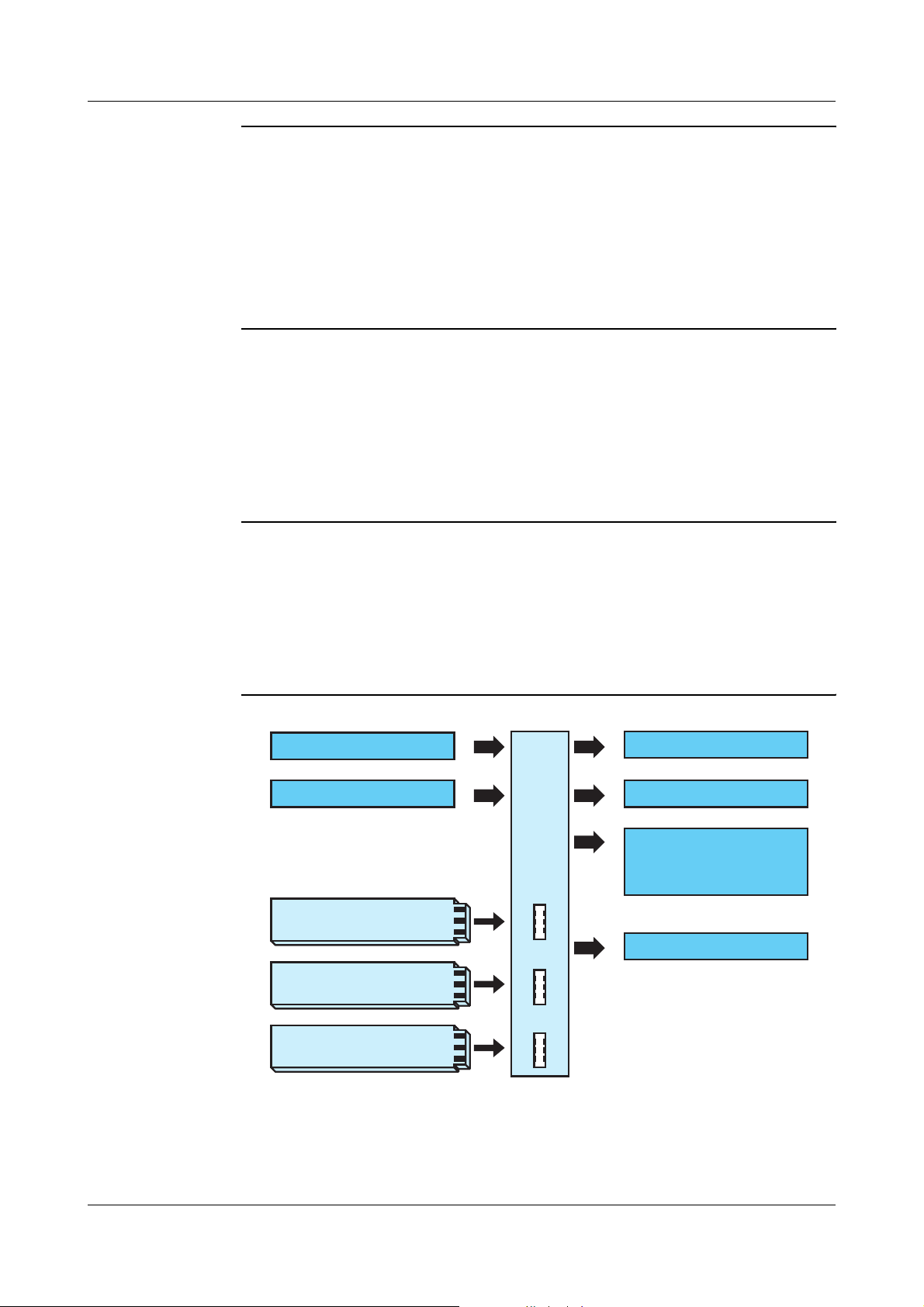
Block
structure
The electrical connection is made at the back of the
instrument by means of screw terminals.
Analog input
2 binary inputs
Option 1
Option 2
Option 3
2 relays (change-over)
2 logic outputs
Voltage supply for
2-wire transmitters
Setup interface
8
Page 9

1.2 Typographical conventions
1 Introduction
Warning
signs
V
*
E
Danger
Caution
Caution
This symbol is used when there may
be danger to personnel if the
instructions are ignored or not
followed correctly!
This symbol is used when there may
be damage to equipment or data if
the instructions are ignored or not
followed correctly!
This symbol is used where special
precautionary measures are required
when handling components liable to
damage through electrostatic
discharge.
Note
signs
H
v
h
Note
Reference
Action
instruction
This symbol is used to draw your
special attention to a remark.
This symbol refers to further
information in other operating
manuals, chapters or sections.
This symbol refers to a description of
an action to be performed.
The individual steps are marked by
this asterisk, e.g.:
EXIT
hPress
EXIT
F
F
9
Page 10

1 Introduction
Representation
Menu items
Blinking
display
Text referring to the setup program is
shown in italics, for example:
„Display/Operation“.
S
E
NS
O
R
10
Page 11
2 Identifying the instrument version
2.1 Type designation
(1) Basic type
701550 Digital Indicator
incl. 1 analog input, 2 binary inputs, 2 relay outputs,
2 logic outputs and 1 setup interface,
Front dimension 96mm x 48mm
(2) Basic type extensions
1 Basic type
Version
8 Standard with factory settings
9 Programming to customer specification
Logic outputs (2 are available as standard)
10/12V
(3) Option slots
1. 2. 3. Option slot Max.
0 0 0 not assigned
111Analog input 2
(universal) 1
2 2 2 Relay (change-over) 2
3 3 3 2 relays (n.o. make) 2
444Analog output 2
5 5 5 2 binary inputs 2
6 6 6 Solid state relay 1A 2
7 7 7 RS422/485 interface 1
8 8 8 PROFIBUS-DP
interface 1
number
Please note:
The position of the
options (slot 1, 2 or 3) is
freely assignable,
however, the max.
number must not be
exceeded.
(4) Voltage supply
23 AC 110—240V -15/+10%, 48—63Hz
25 AC/DC 20—30V, 48—63Hz
(5) Extra codes
000 none
214 Math and logic module
(1) (2) (3) (4) (5)
Ordering code:
Ordering example:
701550 / 1 8 1 – 1 4 0 – 2 3 / 0 0 0
/––/
11
Page 12
2 Identifying the instrument version
View of
option slots
1
2
3
12
Page 13

2 Identifying the instrument version
2.2 Scope of delivery
- Display instrument
- Seal
- Mounting brackets
- Operating Manual B70.1550.0 in DIN A6 format
2.3 Accessories
Mini-CD Mini-CD with demo setup program and PDF
documents (operating manual and further
documentation)
Sales No.: 70/00448699
PC interface PC interface with TTL/RS232 converter and adapter
(socket connector) for setup program
Sales No.: 70/00350260
USB interface PC interface with USB/TTL converter, adapter (socket
connector) and adapter (pins)
Sales No.: 70/00456352
Setup
program
Setup program with startup function (recording and
visualisation measuring data)
Sales No.: 70/00493223
13
Page 14
2 Identifying the instrument version
Setup
program
(continued)
Required hardware:
- PC Pentium IV or compatible
- 256MB RAM, 100MB free fixed disk memory
-CD ROM drive
- free serial or USB interface
Required software:
Microsoft
1
Windows 2000/XP/Vista
14
1. Microsoft is a registered trademark of Microsoft Corporation
Page 15
3.1 Mounting site and climatic conditions
The conditions at the mounting site must meet the
requirements specified in the technical data. The
ambient temperature at the mounting site can range
from 0...55°C with a maximum relative humidity of
≤ 90%.
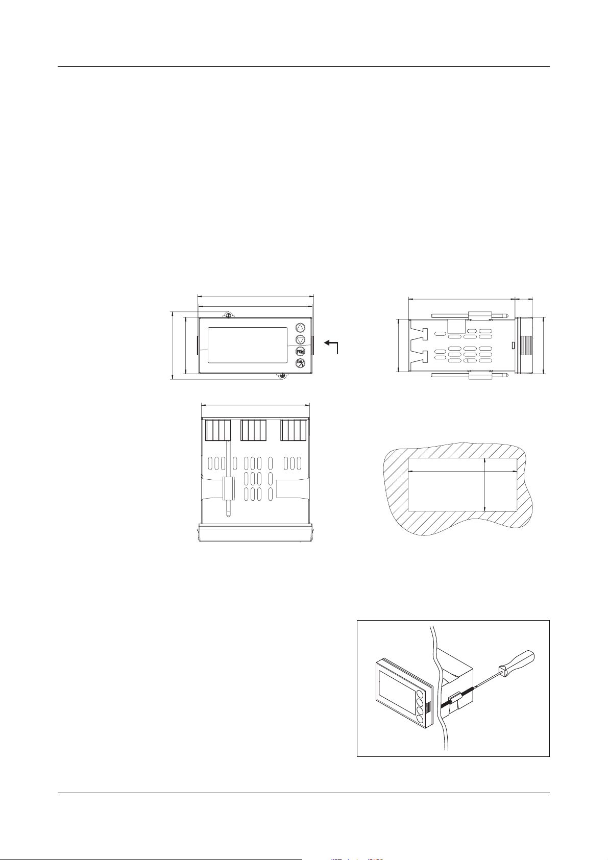
3.2 Dimensions
3 Mounting
48
57.1
99
96
91.5
PC interface adapter
44.5
Panel cut-out
92
90
+0.8
15
48
+0.8
45
3.3 Fitting in position
hPlace the supplied seal
on the instrument body.
hInsert the instrument
from the front into the
panel cut-out.
hFrom the panel rear,
slide the mounting
15
Page 16
3 Mounting
brackets into the guides on the sides of the
housing.
The flat faces of the mounting brackets must make
contact with the housing.
hPlace the mounting brackets against the panel rear,
and tighten them evenly with a screwdriver.
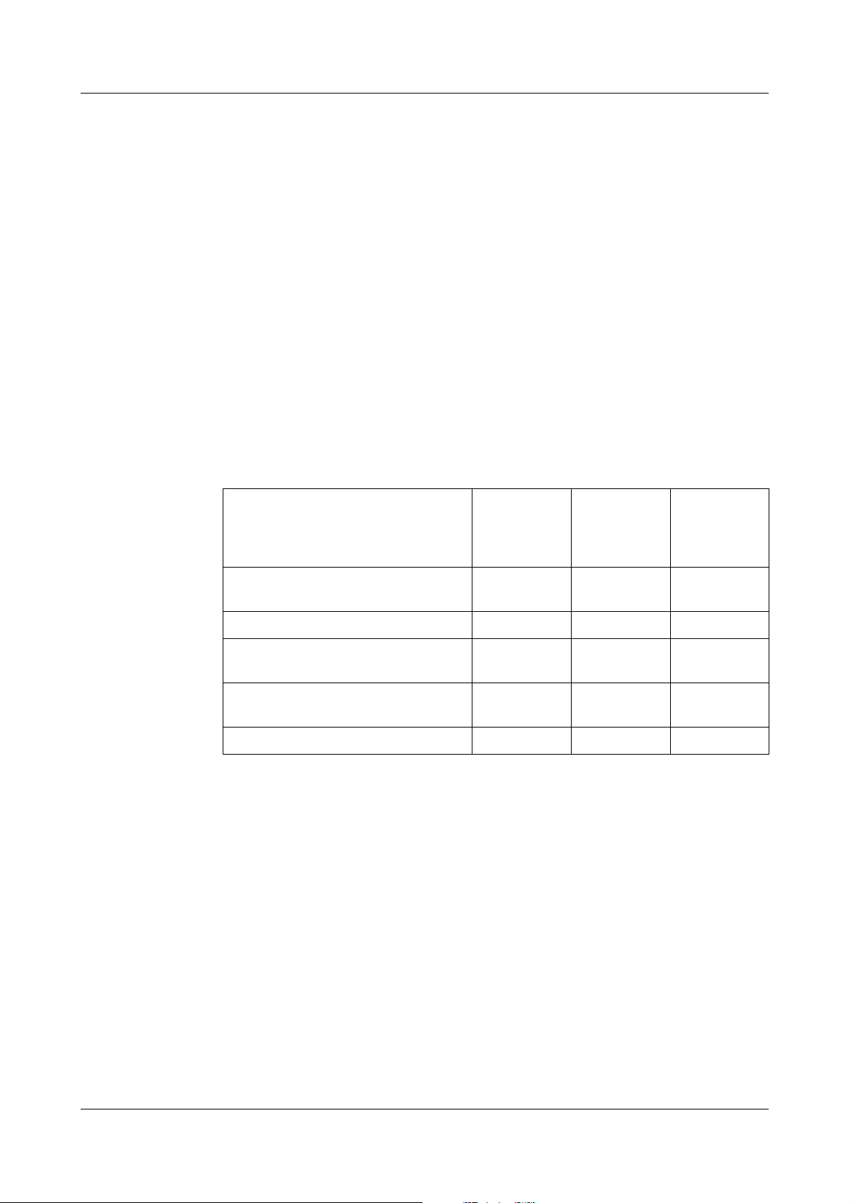
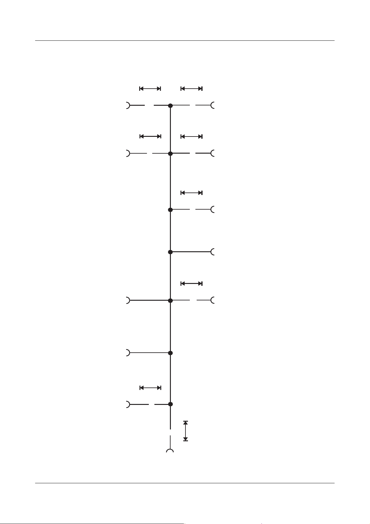
Mounting
controllers
back-to-back/
next to each
other
Minimum spacing of panel cut-outs
without setup plug 30mm 11mm
with setup plug (arrow) 65mm 11mm
Care of the
front panel
The front panel can be cleaned with commercial
detergents and cleaning agents. It has a limited
resistance to organic solvents (e.g. methylated spirits,
white spirit, P1, xylol, etc.). Do not use high-pressure
cleaning equipment.
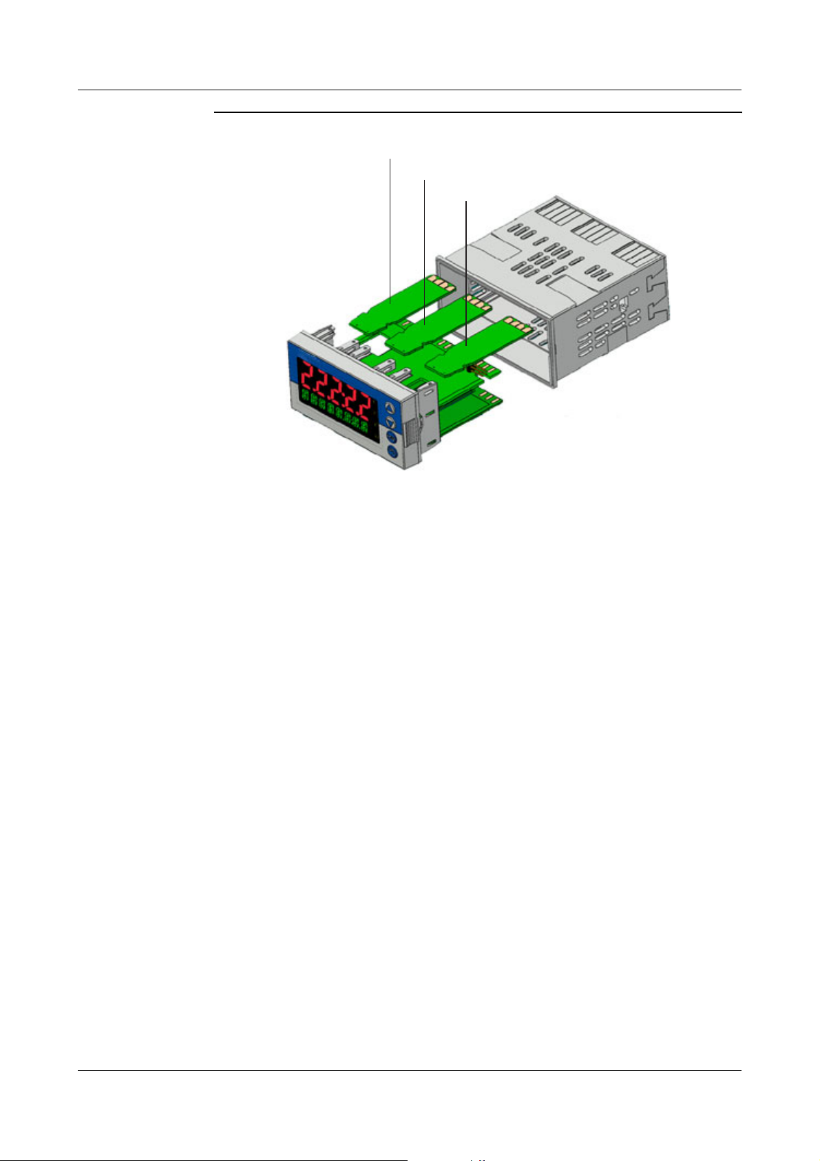
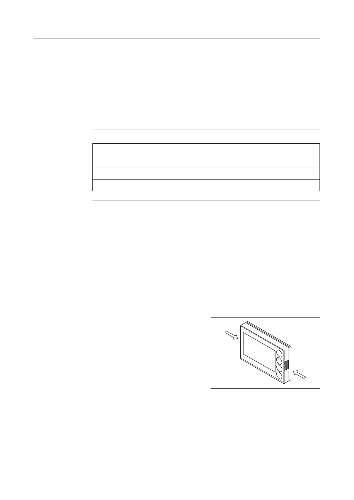
3.4 Removing the plug-in module
The plug-in module can be removed from its housing
for servicing.
horizontal vertical
16
hPress together the
knurled surfaces on the
front panel (left and
right), and pull out the
plug-in module.
H
When re-inserting the plug-in module, ensure
that the latches (beneath the knurled areas)
engage.
Page 17

4.1 Installation notes
- The choice of cable, the installation and the
electrical connection of the instrument must
conform to the requirements of VDE 0100
"Regulations on the Installation of Power Circuits
with Nominal Voltages below 1000V" or the
appropriate local regulations.
- The electrical connection must only be carried out
by qualified personnel.
- The instrument shall be operated by mains
protected with a branch circuitry overcurrent
protection device not more than 20 Amps.
For servicing/repairing a Disconnecting Device shall
4 Electrical connection
be provided to disconnect all conductors.
- The load circuit must be fused for the maximum
relay current, in order to prevent the output relay
contacts becoming welded in the event of a short
circuit occurring at that point.
- Electromagnetic compatibility conforms to the
standards and regulations cited in the technical
data.
vChapter 10.1 „Technical data“
- Run input, output and supply cables separately and
not parallel to one another.
- Sensor and interface cables should be shielded
cables with twisted conductors. Do not run cables
close to current-carrying components or cables.
Ground the shielding on one side.
- Do not connect any additional loads to the supply
terminals of the instrument.
17
Page 18
4 Electrical connection
- The instrument is not suitable for use in areas with
an explosion hazard (Ex areas).
.
Only allow qualified personnel to
V
carry out the electrical connection.
Identify the instrument version by
H
means of the type code.
Installation information on conductor cross
sections and core ferrules
Without core-end ferrule
Core-end ferrule without lip
Core end ferrule with lip
up to 1.5mm
Core end ferrule with lip
above 1.5mm
Twin ferrule with lip
2
2
Minimum
crosssection
0.34mm
0.25mm
0.25mm
1.5mm
0.25mm
2
2
2
2
2
Maximum
crosssection
2.5mm
2.5mm
1.5mm
2.5mm
1.5mm
2
2
2
2
2
Min.
length of
core-end
ferrule
10mm
(stripped)
10mm
10mm
12mm
12mm
18
Page 19
4.2 Electrical isolation
30 V AC
50 V DC
4 Electrical connection
3800 V AC
Input 1
»
30 V AC
50 V DC
Input 2 Solid-state relay outputs
3800 V AC
»
30 V AC
50 V DC
Relay outputs
»
»
Analog outputs
»
Logic outputs
30 V AC
50 V DC
Binary inputs
Setup
interface
RS422/485
PROFIBUS-DP
30 V AC
50 V DC
»
Voltage supply
»
3800 V AC
Voltage supply
for 2-wire transmitters
»
19
Page 20
4 Electrical connection
4.3 Connection diagram
Terminal strips on the back of the instrument:
Option 1Option 2Option 3
Terminal strip 1
(Option slots)
Terminal strip 2
Terminal strip 3
Connection
diagram in the
setup
program
12
17
16
15
5
6
7
10
11
8
6
7
8
9
8
9
6
9
12
13
4
3
3
4
4
5
2
2
N(L+)
1
1
L1(L+)
10
11
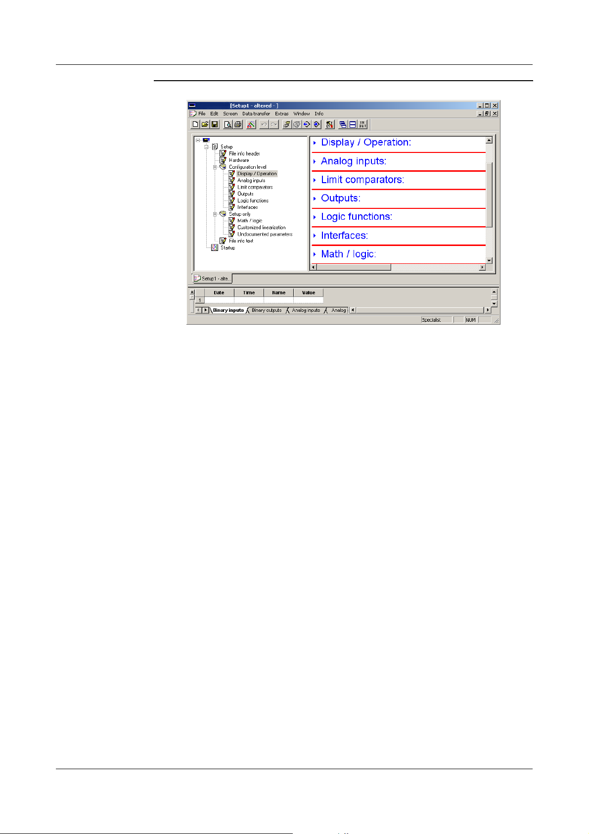
The setup program includes a graphic connection
diagram subject to updates depending on the
configuration or equipment.
It also allows the preparation of a list of connections
containing the hardware equipment and configuration
of the connections.
Connection diagram and list of connections can be
printed out.
vSetup program (Extras -> Connection diagram; or
via Toolbar „IN/OUT“)
20
Page 21
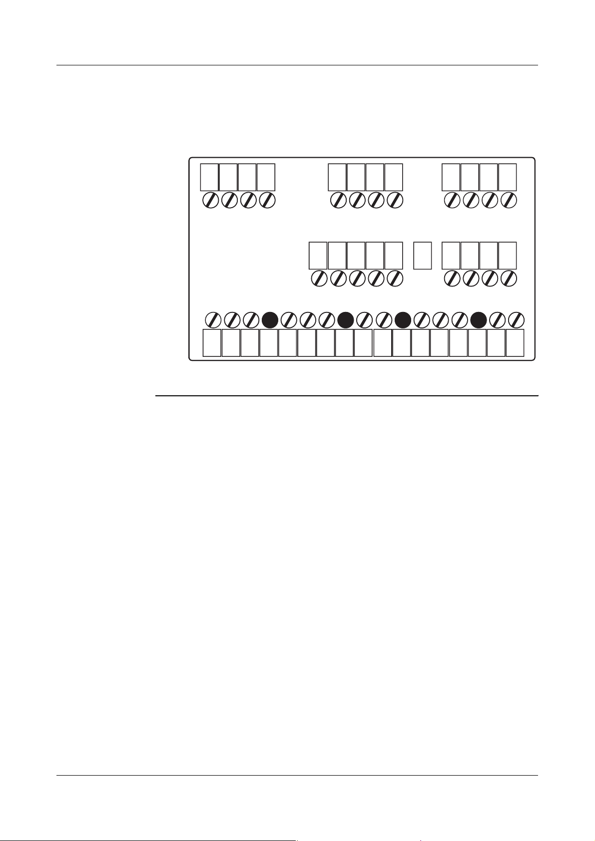
4 Electrical connection
Assignment of terminal strip 3:
Voltage supply and binary outputs 1+2
L1
L+
N
L-
Supply
4
5
6
8
=
U
9
11
12
13
U
L1
AC 110—240V AC/DC 20—30V
N
+
=
15.8—15.2V /
30—50mA
-
Ö
230V/3A
P
S
Voltage supply
for 2-wire transmitters
(No-load voltage approx. 25V)
Binary output 1
L+
L-
Relays
15
16
17
Ö
P
S
230V/3A
Binary output 2
21
Page 22
4 Electrical connection
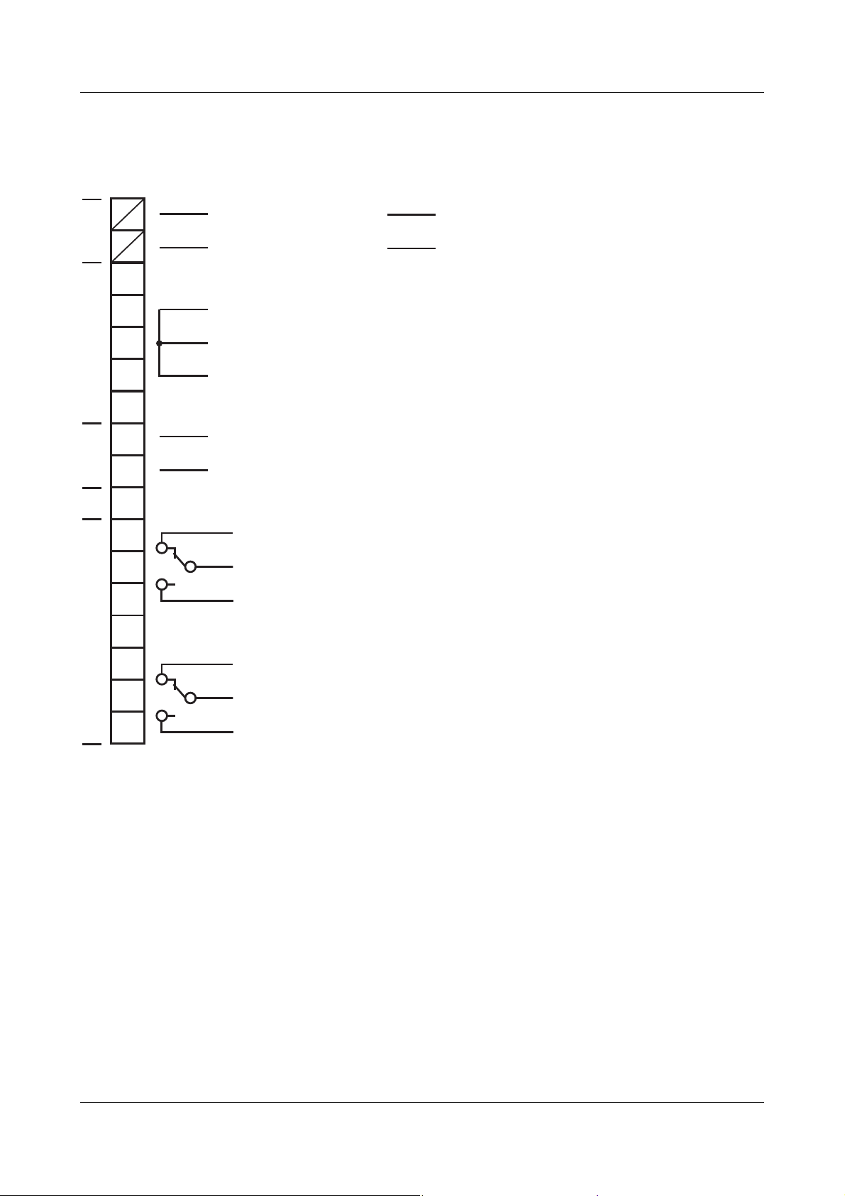
Assignment of terminal strip 2:
Analog input 1, binary inputs 1+2, and binary outputs 3+4
Terminal strip 2
RTD temp.
probe
1
2
3
input 1
Analog
4
1
2
input 1
Analog
3
4
Thermocouple
RTD temp.
probe
Current Voltage
+
-
- /
I
x
Terminal
RTD temp.
probe
0(2)—10V
+
U
x
-
+
~
I
~
x
Resistance
transmitter
E
S
A
Voltage
0—1V
+
U
x
-
-
strip 1*
5
1
6
2
3
4
1
2
3
4
7
8
5
6
7
8
10
11
12
10
11
12
9
9
Binary input
1+2
6
7
1
2
8
Binary
9
10
Position of terminal strip 1 and 2 (on the back of the instrument):
Terminal strip 1
Terminal strip 2
Terminal strip 3
GND
10
11
12
Option 3
15
16
17
Binary output
3+4
(logic 12V)
13
12
10
8
9
11
9
3 (+)
4 (+)
GND (-)
5
6
7
6
7
8
8
9
4
Option 1Option 2
4
5
6
1
2
3
1
2
3
N(L+)
4
L1(L+)
* Assignment of
terminal strip 1
for analog input 2
(see also next page)
22
Page 23
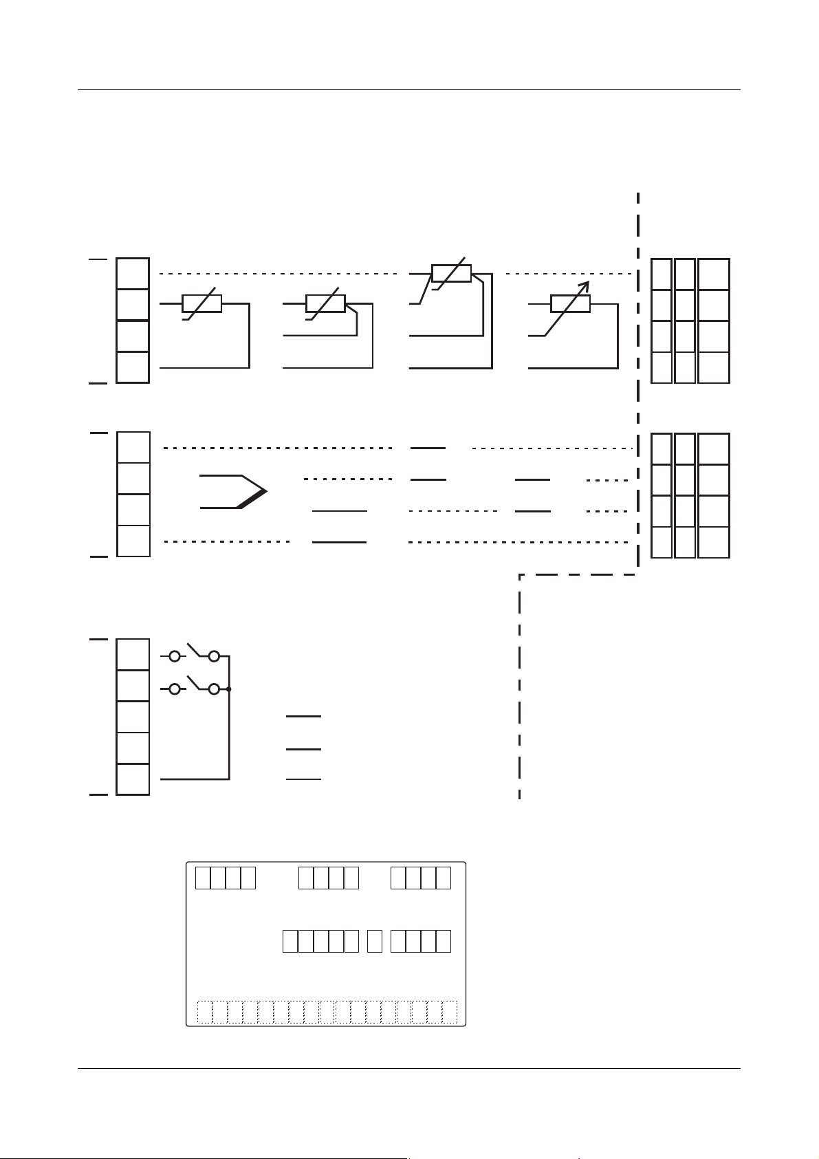
4 Electrical connection
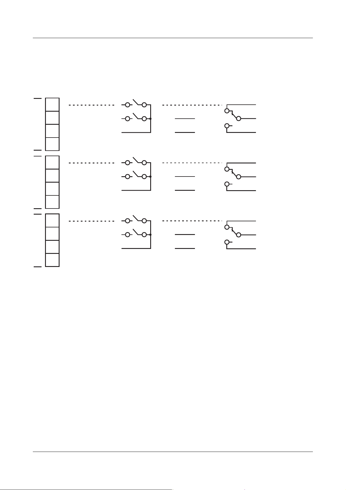
Assignment of terminal strip 1 (option boards):
Inputs, outputs and interfaces
1
2
3
Option 1
4
5
6
7
Option 2
8
9
10
11
Option 3
12
Analog
input
Analog input 2
Connection as
analog input 1
Analog input 2
Connection as
analog input 1
Analog input 2
Connection as
analog input 1
2 binary
inputs
Binary
input 3+4
Binary
input 5+6
Binary
input 7+8
3
4
GND
5
6
GND
7
8
GND
Analog
output
U
/ I
x
Analog
output 5
Ux/ I
Analog
output 6
Ux/ I
Analog
output 7
Relay
(change-over)
Ö
+
x
-
Binary
output 5
+
x
-
Binary
output 6
+
x
-
Binary
output 7
P
S
Ö
P
S
Ö
P
S
H
H
The maximum number of option boards has to be taken into
account (see Chapter 2.1 „Type designation“).
Note numbering of the outputs (see
„OUTPUT““
).
Chapter 7.3 „Outputs
23
Page 24

4 Electrical connection
Assignment of terminal strip 1 (option boards) - continued:
Inputs, outputs and interfaces
1
2
3
Option 1
4
5
6
7
Option 2
8
9
10
11
Option 3
12
2 Relays
(n.o. make)
Binary
output 5+8
Binary
output 6+9
Binary
output 7+10
Solid-state
relay
5
8
6
9
7
10
Binary
output 5
Binary
output 6
Binary
output 7
PROFIBUS
VP (+5 V)
RxD/TxD-P (B)
RxD/TxD-N (A)
DGND
VP (+5 V)
RxD/TxD-P (B)
RxD/TxD-N (A)
DGND
VP (+5 V)
RxD/TxD-P (B)
RxD/TxD-N (A)
DGND
RS422
RxD +
RxD TxD +
TxD -
RxD +
RxD TxD +
TxD -
RxD +
RxD TxD +
TxD -
RS485
RxD/
TxD +
RxD/
TxD -
RxD/
TxD +
RxD/
TxD -
RxD/
TxD +
RxD/
TxD -
H
H
24
The maximum number of option boards has to be taken into
account (see Chapter 2.1 „Type designation“).
Note numbering of the outputs (see
„OUTPUT““
).
Chapter 7.3 „Outputs
Page 25

4 Electrical connection
4.4 Termination resistor for the RS422/485 interface
Setting
resistors
To ensure fault-free operation of several instruments
in a line structure, their internal termination resistors
must be activated at the start and end
.
hPull plug-in module out towards the front by
pressing on the knurled areas
hUsing a suitable aid (e.g. ballpoint pen), press all the
white switches into the same direction
Bus
h Push all 5 switches down
termination
active
No
h Push all 5 switches up
bus
termination
(ex-factory)
hRe-insert the module into the housing
Check hPress the P + i keys
When checking the software version and the
termination resistors activated, an additional decimal
point appears behind the version number (top
display).
Example of
active:
inactive:
version number 01.01
01.01.
01.01
:
25
Page 26

4 Electrical connection
4.5 Connection of the PROFIBUS-DP connector
Mounting the
adapter
Assignment of
the 9 pole
D-Sub socket
hIdentify option slot with the PROFIBUS-DP
interface by means of the type code (in the case of
pre-configured instruments)
2
1
3
1
In this example, the
PROFIBUS-DP
interface is in
option slot 1.
Pin at
D-Sub
socket
2
3
1
2
3
4
4
5
6
Pin at terminal
strip 1: Signal
(Example for
option slot 1)
6
7
Designation
L1(L+)
N(L+)
4
5
6
8
6 1: VP Voltage supply,
positive
3 2: RxD/TxD-P Receive/Transmit
data, positive
8 3: RxD/TxD-N Receive/Transmit
data, negative
5 4: DGND Ground
To fit the D-Sub adapter, open the black housing
*
of the adapter board; otherwise the connection
screws in the instrument back are not
accessible.
It is important to note that the adapter is fitted in
the position shown above to ensure correct pin
assignment.
26
Page 27

5.1 Displays and controls
(1)
5 Operation
(4)
(2)
(3)
(1) 7-segment display (measured value display)
five-digit, red; decimal place is configurable
(automatic adjustment on display overflow)
(2) 16-segment display (24 character ticker,
parameter name, level symbols)
eight-digit, green or red;
decimal place configurable
(3) Indication
yellow; for four switch positions of max. four
outputs (display lit = ON)
(4) Keys
The displays are configurable.
vChapter 7.5 „Display / Operation „DISPLAY““
27
Page 28

5 Operation
5.2 Level concept
The parameters for instrument setting are organised
at different levels.
Normal display
EXIT
F
> 2 sec
or time-out
Navigation principle
EXIT
F
i
d
P
P
USER
OPERATOR
CONFIG
1. USER only
1
visible if user data
is configured (setup program)
P
P
P
i
d
Time-out
H
If no key is pressed for 180 secs the instrument
changes back to normal display!
vChapter 6 „Operator level“
User level
Up to eight freely chosen
parameters
Operator level
Process data
Configuration level
- INPUT (analog inputs)
- LIMITCOM (limit comparators)
- OUTPUT (outputs)
- BINFUNCT (binary functions)
- DISPLAY (display)
- INTERFCE (interfaces)
User data
„USER“
vChapter 7 „Configuration“
vSetup program (Display/Operation -> Operation ->
Operation time-out)
The setup program allows the display and editing up
to 8 freely chosen parameters at this level.
vSetup program (Display/Operation -> User data ->
Parameters 1...8)
The user can assign a symbol for the representation
of each parameter. Otherwise, the default symbol will
appear. All letters and numbers that can be presented
by a 16 segment display are permissible.
28
Page 29

5.3 Level inhibit
Access to the individual levels can be prevented.
Code Configuration level
0enabled
1 inhibited
5 Operation
hEnter code by pressing
P and d (simultaneously
for > 5sec).
hChange code by pressing
hEnter code by pressing
P (display blinks!)
i and d. Ex-factory: all
levels enabled.
EXIT
hReturn to normal display by pressing or
EXIT
F
F
automatically after approx. 180 secs
The configuration level can also be inhibited via the
binary function.
vChapter 7.4 „Binary functions „BINFUNCT““
29
Page 30

5 Operation
5.4 Entries and operator prompting
When entries are made within the levels, the
parameter symbol appears in the lower display.
Select
P
id/
NS
R
O
S
E
hSelect parameter by pressing
hChange to the entry mode by pressing
Alter
E
S
R
O
NS
i or d.
i
d
P (lower
display blinks!)
hAlter value by pressing i and d
The value alters dynamically for as long as the key
is kept pressed.
hAssign the value by pressing
P or automatically
after 2 secs
or
EXIT
hCancel the entry with .
EXIT
F
F
The value will be assigned.
To enter digits after the decimal point, the value
H
of system point must be set accordingly (see
page 57).
For the display of measurement values of the
analog inputs, the digits after the decimal point
can be set separately (see page 38).
30
Page 31

Access
6 Operator level
Normal display
EXIT
F
> 2 sec
P
or time-out
Navigation principle
EXIT
F
i
d
P
USER
1
d
P
OPERATOR
1. USER only visible
if user data is configured
(setup program)
Operator level
Process data
31
Page 32

6 Operator level
Process data Process data is shown in the operator level in
accordance with the configuration.
Symbol Meaning
INPUT1 Measured value of analog input 1
INPUT2 Measured value of analog input 2 (only if
available)
MIN INP1 Minimum value for analog input 1
(only if function is activated)
MAX INP1 Maximum value for analog input 1
(only if function is activated)
HOLD1 Hold value for analog input 1
(only if function is activated)
MIN INP2 Minimum value for analog input 2
(only if analog input 2 is available and
function activated)
MAX INP2 Maximum value for analog input 2
(only if analog input 2 is available and
function activated)
HOLD2 Hold value for analog input 2
(only if analog input 2 is available and
function activated)
MATHE1 Calculated result of mathematical formula 1
(only if mathematics module is available or
if analog output 2 is available as a
prerequisite for function „Humidity“,
„Difference“ or „Ratio“)
MATHE2 Calculated result of mathematical formula 2
(Same conditions as with MATHE1)
32
Page 33

Access
7 Configuration
Normal display
EXIT
> 2 sec
F
or time-out
Navigation principle
EXIT
F
i
d
H
Levels can be inhibited
P
P
vChapter 5.3 „Level inhibit“
USER
OPERATOR
CONFIG
1. USER only visible
1
d
d
P
- INPUT (analog inputs)
- LIMITCOM (limit comparators)
- OUTPUT (outputs)
- BINFUNCT (binary functions)
- DISPLAY (display)
- INTERFCE (interfaces)
if user data is configured
(setup program)
Configuration level
H
H
Parameters are not displayed if the equipment
level does not permit the function assigned to the
parameter. Example: Analog output 2 cannot be
configured if no second analog output is
implemented in the instrument.
Some parameters can only be programmed
through the set-up program. In the following
tables, these are marked in the „Parameter“
column with „(Setup)“.
33
Page 34

7 Configuration
Analog
selector
With some parameters, you can choose from a series
of analog values. To provide you with an overview,
this selection is listed below.
Value Description
0
deactivated
1
analog input 1
2
analog input 2
3
(reserved)
4
(reserved)
5
math 1
6
math 2
7
(reserved)
8
(reserved)
9
(reserved)
10
(reserved)
11
analog marker
12
minimum value input 1
13
minimum value input 2
14
(reserved)
15
(reserved)
16
maximal value input 1
17
maximal value input 2
18
(reserved)
19
(reserved)
20
hold value input 1
21
hold value input 2
22
(reserved)
23
(reserved)
24
any analog value
25
internal Pt100
26
sampling cycle time
34
Page 35

7.1 Analog inputs „INPUT“
7 Configuration
Configuration
Analog inputs
Limit
comparators
Outputs
Binary
functions
Display /
Operation
Interfaces
Sensor type
Depending on the instrument version, up to two
analog inputs are available.
➔ INPUT1 (analog input 1) ➔
➔ INPUT2 (analog input 2) ➔
Parameter Value/
Selection
SENSOR 0
Description
No function
1
RTD temperature probe in 3-wire circuit
2
RTD temperature probe in 2-wire circuit
3
RTD temperature probe in 4-wire circuit
4
Thermocouple
5
Resistance transmitter
7
0…20mA
8
4 ... 20mA
9
0…10V
10
2…10V
11
0 ... 1V
Factory set on analog input 2: no function
Factory settings are shown
bold
.
35
Page 36

7 Configuration
➔ INPUT1 (analog input 1) ➔
➔ INPUT2 (analog input 2) ➔
Linearization
Parameter Value/
Selection
LINEAR 0
10
11
12
13
14
15
16
17
18
19
20
21
22
23
Description
Linear
1
Pt100 DIN
2
Pt500 DIN
3
Pt1000 DIN
4
KTY11-6
5
Pt100 GOST
6
Pt 50 GOST
7
Cu100
8
Cu50
9
Chromel-Copel
W5Re-W26Re C
W3Re-W25Re D
NiCr-Con E
Cu-Con T
Fe-Con J
Cu-Con U
Fe-Con L
NiCr-Ni K
Pt10Rh-Pt S
Pt13Rh-Pt R
Pt30Rh-Pt6Rh B
NiCrSi-NiSi N
W3Re-W26Re
Customised linearization
Measurement
offset
OFFSET -19999…
0
…
99999
For customised linearization, a maximum of 10
knee points can be implemented, or a 4th order
polynomial function programmed
the setup program)
For the „KTY11-6“ linearization, the resistance
Ω
is 2k
program and with 2-wire circuit)
The measurement offset is used to correct a
measured value by a certain amount upward or
downward. Examples:
Measured displayed
value offset value
294.7 +0.3 295.0
295.3 - 0.3 295.0
To enter digits after the decimal point, the value
of system point must be set accordingly (see
page 57).
Special case: „2-wire circuit“
If the input is connected to an RTD temperature
probe in 2-wire circuit, then the lead resistance
is set in ohms here.
at 25°C
.
(setting only through the setup
(only through
.
36
Factory settings are shown
bold
.
Page 37

➔ INPUT1 (analog input 1) ➔
➔ INPUT2 (analog input 2) ➔
7 Configuration
Scale low point
Scale high point
Filter time
constant
Parameter Value/
Selection
SCAL-LOW -19999…
0
…
99999
SCAL-HI -19999…
100
…
99999
FILTER 0.0…
0.6
…
100.0
Description
On transducers with standard signal and on
resistance potentiometers, a display value is
assigned to the physical signal (scaling).
Example: 0—20mA 0—1500°C.
The range of the physical signal can be 20 %
wider or narrower without generating an out-ofrange signal.
With a standard signal and customised
linearization, the display range coincides with
the linearization range (range of the x values).
For the above example this means:
Start x = 0, End x = 20, in order that the display
range goes from 0 to 1500 °C.
If the range of the x values is smaller, the display range is reduced accordingly.
To adjust the digital input filter
(time in seconds; 0.0 sec = filter off).
63% of the alterations are acquired after 2x
filter time constant (2nd order filter) at a filter
time step change.
When the filter time constant is large:
- high damping of interference signals
- slow reaction of the process value display
to process value changes
- low limit frequency (low-pass filter)
Fine adjustment
begin value
Fine adjustment
end value
FINEADJB -19999…
0
…
99999
FINEADJE -19999…
1
…
99999
Factory settings are shown
These parameters are factory-
(Activation in the setup program > Non
documented parameters; please contact the
manufacturer.)
These values cannot be accepted by
another instrument.
A
If these values have been altered by
mistake, this setting has to be canceled
using the procedure described under
„Customised fine tuning“.
See description on page 39.
bold
.
deactivated
.
37
Page 38

7 Configuration
➔ INPUT1 (analog input 1) ➔
➔ INPUT2 (analog input 2) ➔
Decimal point
Correction
value KTY at
25°C
Parameter Value/
Selection
DECPOINT 0
(Setup) 0…
2000
…
4000
Factory settings are shown
Description
no digit after the decimal point
1
one digit after the decimal point
2
two digits after the decimal point
3
three digits after the decimal point
7
System point
This setting is only valid for the display of
measurement value of analog input 1 or 2!
(Adjustment in the setup program under
Display/Operation -> Display -> Channel name)
Resistance in ohms at 25°C/77°F for
„KTY 11-6“ linearisation
Adjustment only possible in the setup program:
-> Analog inputs -> Analog input 1 or 2
bold
.
Temperature
unit
Temperature unit
Mains
frequency
Mains frequency
Sampling cycle
time
Sampling cycle
time
➔ INPUT (analog inputs general) ➔
Parameter Value/
Selection
UNIT
FREQUENC
CYCLE-t
Factory settings are shown
Description
01deg. Celsius
deg. Fahrenheit
Unit for temperature values
0150Hz
60Hz
Adaptation of the conversion time of the input
circuitry to the supply frequency
0
50ms
1
90ms
2
150ms
3
250ms
bold
.
38
Page 39

7 Configuration
Customised
fine adjustment
The customised fine adjustment is used to correct the
values displayed by the instrument. This may be
necessary, for example, after a system validation, if
the displayed values no longer coincide with the
actual values at the point where the measurement is
taken.
Using a reference measuring instrument, two
measured values are determined which should be as
far apart as possible (start value, end value). Ensure
that the measuring conditions are stable. Enter the
reference value found as the start value (FINEADJB)
or end value (FINEADJE) on the instrument to be
tuned.
Example The temperature inside an oven is measured with an
RTD temperature probe and displayed on an
instrument. The reading on the instrument deviates
from the actual temperature as a result of the sensor
temperature drifting. At 20°C the instrument reads
15°C, at 80°C it shows 70°C (exaggerated example
for better understanding).
Sensor
15°C / 70°C
20°C / 80°C
20°C / 80°C
Oven
Display on the instrument
Reference measuring instrument
39
Page 40

7 Configuration
Procedure:
hStep 1: The measurement carried out with the
reference measuring instrument shows a constant
oven temperature of 20°C.
hStep 2: Enter value 20 as start value (FINEADJB) at
the instrument.
hStep 3: The oven temperature is increased to 80°C,
the temperature is still controlled by a
reference measuring instrument.
The temperature must remain constant.
hStep 4: Enter the value 80 as end value
(FINEADJE) at the instrument.
The following diagram shows the changes in the
characteristic curve caused by the fine adjustment
(point of intersection with the x axis as well as ascent)
Display
(Instrument)
80
70
After fine
adjustment
Before fine
adjustment
20
15
Measurement
(Reference)
40
20 80
Page 41

7 Configuration
Special case:
Offset
Repeated
fine adjustment
If the deviation between measured value and
displayed value at the low and high measuring point
is identical, an offset correction is sufficient (ascent
remains unchanged). In this case, fine adjustment is
not required.
vMeasured value correction (offset), page 36
Reset the fine adjustment prior to repeating it. For this
purpose, program start value (FINEADJB) and end
value (FINEADJE) are given the same value. This
automatically sets the start value to 0 and the end
value to 1.
Always check the start value and the end value
*
prior to starting fine adjustment.
Reset the fine adjustment, if they deviate from
the factory-set values 0 (FINEADJB) and 1
(FINEADJE).
41
Page 42

7 Configuration
7.2 Limit comparators „LIMITCOM“
Configuration
Analog inputs
Limit
comparators
Outputs
Binary
functions
Display /
Operation
Interfaces
Limit
comparator
functions
Hysteresis
function
Limit comparators (threshold monitors, limit contacts)
can be used to monitor an input variable (process
value for the limit comparator) against a fixed limit
value or another variable w (setpoint value for the limit
comparator). When a limit value is exceeded, a signal
can be output or an internal controller function
initiated.
4 limit comparators are available.
Limit comparators can have different switching
functions (lk1 to lk8). The switching differential HySt
(HYSTERES) can be set and is, in all cases,
symmetrical in relation to the limit value.
The hysteresis function (symmetrical, asymmetrical)
defines the ranging of the switching differential
around the limit value (adjustment in the setup
program).
42
Page 43

7 Configuration
Limit value AL
relative to
setpoint
value w
lk1 symmetrical
asymmetrical, left asymmetrical, right
The limit comparator functions lk1 to lk6 monitor the
input variable for a limit value AL (LIMVALUE) to be set,
the absolute value depending on setpoint value w.
ON
AL
HySt
w
Measurement
lk2 symmetrical
asymmetrical, left asymmetrical, right
ON
HySt
AL
w
Measurement
43
Page 44

7 Configuration
lk3 symmetrical
asymmetrical, left asymmetrical, right
ON
HySt
AL
Measurement
w
lk4 symmetrical
asymmetrical, left asymmetrical, right
ON
HySt
AL
Measurement
w
44
Page 45

lk5 symmetrical
7 Configuration
ON
AL
HySt
asymmetrical, left asymmetrical, right
lk6 symmetrical
ON
w
w
Measurement
AL
HySt
Measurement
asymmetrical, left asymmetrical, right
Example of a
variable
setpoint value
The measurement is monitored (analog input 1). The
setpoint value w default value is manually entered via
a potentiometer connected to analog input 2. For this,
analog input 2 is selected as setpoint value
(LCSETVAL).
45
Page 46

7 Configuration
Fixed limit
value AL
lk7 symmetrical
asymmetrical, left asymmetrical, right
In the case of the limit comparator functions lk7 and
lk8, the measurement is monitored with respect to a
fixed limit value AL (LIMVALUE).
ON
HySt
Measurement
AL
lk8 symmetrical
asymmetrical, left asymmetrical, right
ON
HySt
Measurement
AL
46
Page 47

➔ LIMITC 1 (limit comparator 1) ➔
➔ LIMITC 2 (limit comparator 2) ➔
➔ LIMITC 3 (limit comparator 3) ➔
➔ LIMITC 4 (limit comparator 4) ➔
7 Configuration
Function
Limit value
Hysteresis
Fixed limit
comparator
setpoint value
Parameter Value/
Selection
FUNCTION
LIMVALUE -19999…
0
…
99999
HYSTERES 0…1…
99999
FIXLCVAL -19999…
0
…
99999
Description
0
no function
1
lk1
2
lk2
3
lk3
4
lk4
5
lk5
6
lk6
7
lk7
8
lk8
Limit value to be monitored
(see limit comparator functions lk1...lk8:
limit value AL)
Switching differential in respect to the limit
value
(see limit comparator functions lk1...lk8:
hysteresis HySt)
A fixed setpoint value can be set for the
limit comparator (lk1...lk6).
The limit comparator setpoint value
LCSETVAL must be deactivated for the
fixed setpoint value to be active.
Action/
Range response
Switch-on delay
Switch-off delay
ACT-RESP
ON DELAY0…9999 Delays the switch-on edge by a definable
OFFDELAY0…9999 Delays the switch-off edge by a definable
Factory settings are shown
0
absolute/off
1
relative/off
2
absolute/on
3
relative/on
Defines the switching action of the limit
comparator and the switch status for an
overrange or underrange (signal at „Out of
Range“).
See description on page 49.
time period (time in seconds).
time period (time in seconds).
bold
.
47
Page 48

7 Configuration
➔ LIMITC 1 (limit comparator 1) ➔
➔ LIMITC 2 (limit comparator 2) ➔
➔ LIMITC 3 (limit comparator 3) ➔
➔ LIMITC 4 (limit comparator 4) ➔
Acknowledgement
Pulse time
Limit
comparator
actual value
Limit
comparator
setpoint value
Parameter Value/
Selection
ACKNOWL
PULSE-t
0
…9999 The limit comparator resets automatically
LCACTVAL (analog
selector)
Analog
input 1
LCSETVAL (analog
selector)
deactivated
Description
0
no acknowledgement
1
acknowledgement only possible with the
limit comparator inactive
2
acknowledgement always possible
For setting with acknowledgement, the limit
comparator is latching, which means, it
remains „ON“ even when the switch-on
condition is no longer present.
The limit comparator must be reset by
pressing the
EXIT
( d + ) keys or a binary signal.
EXIT
F
F
after an adjustable time period (time in
seconds).
Input variable for limit comparator
(see limit comparator functions lk1...lk8:
Measurement)
v „Analog selector“, page 34
Setpoint value for limit comparator
(see limit comparator functions lk1...lk6:
setpoint value w)
v „Analog selector“, page 34
Hysteresis
function
(Setup)
When LCSETVAL is deactivated, parameter
FIXLCVAL can be used to enter a fixed
default setpoint value.
symmetrical
Switching differential ranging around the
limit value
asymmetrical
left
Adjustment only possible in the setup
program:
asymmetrical
-> Limit comparators -> 1 ... 4
right
Factory settings are shown
bold
.
48
Page 49

7 Configuration
Switching
action
Switching action means: limit comparator reaction to
a limit value or setpoint value change as well as to
Power ON.
„absolute“ switching action:
At the time of the change, the limit comparator reacts
according to its function.
„relative“ switching action:
Following Power ON, the limit comparator remains in
its „OFF“ switch position, even if the process value is
within the switch-on range.
If the setpoint value or the limit value is altered while
the limit comparator is in its „OFF“ position, which
leads to the actual value now being in the switch-on
range, the limit comparator still remains in the „OFF“
switch position.
The limit comparator will only resume operation
according to its function when the process value is
outside of the switch-on range. In other words: it
remains „OFF“ until the process value has again
reached the switch-on range.
See the following example:
49
Page 50

7 Configuration
Example of the
switching
action
„relative“:
Monitoring the actual value x with function lk4,
change of setpoint value w
→w
1
2
a) Start situation:
Limit comparator „OFF“, as actual value x not in the
switch-on range (grey area).
AL
ON
OFF
w= x
1
b) Situation at the time of the setpoint value change:
Limit comparator remains „OFF“, although the actual
value is now in the switch-on range.
AL
ON
OFF
w
x
2
c) Actual value has left the switch-on range:
Limit comparator operates according to its function
again, which means it remains „OFF“ until the actual
value has reached the switch-on range again.
AL
ON
50
OFF
w= x
2
Page 51

7.3 Outputs „OUTPUT“
7 Configuration
Configuration
Analog inputs
Limit
comparators
Outputs
Binary
functions
Display /
Operation
Interfaces
Numbering of
the outputs
Configuration of the instrument outputs is subdivided
into analog outputs (OUTANALG; max. 2) and binary
outputs (OUTLOGIC; max. 10). Binary outputs are
relays, solid-state relays and logic outputs. Display
and numbering of the outputs depends on the
assignment of the option slots.
The switching states of the binary outputs 1...4 are
shown in the display (K1…K4).
Standard for all instrument versions:
(Binary) output 1 = relay
(Binary) output 2 = relay
(Binary) output 3 = logic output
(Binary) output 4 = logic output
Extended numbering of the option slots:
Option
slot
Plug-in
board with
1 analog
output
Plug-in
board with
1 binary
output
(relay or
Plug-in
board with
2 binary
outputs
(2 relays)
solid-state
relay)
Option 1Output 5 Output 5 Output 5+8
Option 2Output 6 Output 6 Output 6+9
Option 3Output 7 Output 7 Output 7+10
51
Page 52

7 Configuration
➔ OUTLOGIC (binary outputs) ➔
Binary
output 1
...
Binary
output 10
Inversion
Parameter Value/
Selection
OUTPUT 1
...
OUTPUT10
(Setup) active
inactive
Description
0
no function
1
Binary input 1
2
Binary input 2
3
Binary input 3
4
Binary input 4
5
Binary input 5
6
Binary input 6
7
Binary input 7
8
Binary input 8
9
Limit comparator 1
10
Limit comparator 2
11
Limit comparator 3
12
Limit comparator 4
13
Logic formula 1
14
Logic formula 2
15
Binary marker
16
(reserved)
17
(reserved)
18
(reserved)
Function inverted
Function not inverted
Inversion also affects function „Deactivated“,
i. e. the output is always activated!
Adjustment only possible in the setup program:
-> Outputs -> Binary outputs
Factory settings are shown
bold
.
52
Page 53

7 Configuration
➔ OUTANALG (analog outputs) ➔ Output 5 ➔
➔ Output 6 ➔
➔ Output 7 ➔
Parameter Value/
Selection
Function FUNCTION
Type of signal SIGNAL
Range error RANG ERR0…101 Output signal (in % of the value range) for
Scale low point SCAL-LOW
Scale high point
SCAL-HI -19999…
(analog
selector)
deactivated
-19999…
0
…
99999
100
…
99999
Description
Function of the output
v „Analog selector“, page 34
0
0...10V
1
2...10V
2
0...20mA
3
4...20mA
Physical output signal
an overrange or underrange.
101=last output signal
A value range of the output variable is
assigned to a physical output signal. The
ex-factory setting corresponds to an output
variable with a value range of 0...100.
Example:
Via an analog output (0 … 20mA), a
temperature ranging between 150 … 500°C
is to be output.
i.e.: 150 … 500°C 0…20mA
Scale low point: 150 / Scale high point: 500
Offset
(Setup) -19999…
0
…
99999
Factory settings are shown
The offset is used to correct the output
signal by a certain amount upwards or
downwards.
Examples:
Original Output
value Offset value
294.7 +0.3 295.0
295.3 - 0.3 295.0
To enter digits after the decimal point, the
value of system point must be set
accordingly (see page 57).
Adjustment only possible in the setup
program:
-> Outputs -> Analog outputs
bold
.
53
Page 54

7 Configuration
7.4 Binary functions „BINFUNCT“
Configuration
Analog inputs
Limit
comparators
Outputs
Binary
functions
Display /
Operation
Interfaces
Switching
action
Binary signals of binary inputs, limit comparators and
logics can be assigned functions.
Potential-free contact
ON
Switch-on
edge
OFF
or switching pulse
ON - contact closed
OFF - contact open
t
The following binary functions react to switch-on
edges:
- Acknowledge limit comparator
- Reset min/max value
- Tare function
- Reset tare function
- Go to the next scroll parameter
All remaining binary functions react to switch-on or
switch-off states.
54
Page 55

7 Configuration
Binary input 1
...
Binary input 8
Limit
comparator 1
...
Limit
comparator 4
Logic 1
Logic 2
Parameter Value/
Selection
B-FUNCT1
B-FUNCT8
LCFUNCT1
LCFUNCT4
L-FUNCT1
L-FUNCT2
Description
0
no function
1
Key inhibit
2
Level inhibit
3
Display off (keys inactive)
4
Acknowledge limit comparator
5
Hold function
6
Reset min/max value
7
Tare function
8
Reset tare function
9
Tex t disp la y
10
Go to the next scroll parameter
11
Colour change
Level inhibit:
The configuration level is inhibited.
Tare function:
The tare function is used to zero the display
value of the analog inputs and values (math)
derived from these inputs. The function is reset
after Power ON.
Further
functions via
setup program
Text display:
With the binary function active, a configurable
text appears on the lower display: This text can
be uniquely defined
program)
Factory settings are shown
.
(only through the setup
bold
.
Several binary functions can be combined with each
other in the setup program. The text display can be
configured as an information or as an alarm text (with
colour change).
No information or alarm texts are shown when
*
the instrument is in the USER, OPERATOR or
CONFIGURATION level.
55
Page 56

7 Configuration
7.5 Display / Operation „DISPLAY“
Configuration
Analog inputs
Limit
comparators
Outputs
Binary
functions
Display /
Operation
Interfaces
Display 1
(upper display)
Display 2
(lower display)
The values to be shown, the type of presentation (e.g.
text, pseudo bargraph) and the display settings (e.g.
colour, brightness) can be configured under this menu
item.
Furthermore, start delay after Power ON, operation
time-out, level inhibit and function key assignment
can be defined here.
Parameter Value/
Selection
DISPLAY1 (analog
selector)
Analog
input 1
DISPLAY2 (analog
selector)
deactivated
Description
Display value for the upper display
v „Analog selector“, page 34
Display value for the lower display
v „Analog selector“, page 34
Display type
(lower display)
Display colour
(lower display)
DISPTYPE
COLOUR
0
Value
1
Channel name
2
Process display text
3
Unit and value display
4
Pseudo bargraph display
Channel name (max. 8 characters), process
display text (max. 24 characters), unit (max. 2
characters) as well as bargraph scaling can
only be entered through the setup program.
For better legibility we recommend the
exclusive use of capitals, numbers as well as
the following special characters:
° % / \ ( ) + - < > _ | ,
Enter a space at the end of text comprising
more than 8 and less than 24 characters.
01green
red
Factory settings are shown
bold
.
56
Page 57

7 Configuration
Ticker time
(ticker)
Decimal point
(system point)
Parameter Value/
Selection
TICKER-t
DECPOINT
Description
0
100ms (fast ticker)
1
200ms
2
300ms
3
400ms
4
500ms
5
600ms
6
700ms
7
800ms
8
900ms
9
1000ms
10
1100ms (slow ticker)
0
no digit after the decimal point
1
one digit after the decimal point
2
two digits after the decimal point
3
three digits after the decimal point
If the value to be displayed cannot be shown
including the programmed decimal point, the
number of digits after the decimal point are
automatically reduced. If subsequently the
measured value contains less digits, the
reading appears with the decimal point as
programmed.
Brightness
Time-out
Start
delay time
Min/max mode
Hold
(Value)
BRIGNESS0…5 (bright) 0...5 (dark)
TIMEOUT 0…
START-t
MIN-MAX
(Setup)
180
…
255
0
…3600 Start delay time in seconds after Power ON
active
not
active
Time period in seconds, after which the
instrument automatically returns to normal
display if no key is pressed.
0
Min/max mode inactive
1
Min/max mode active for analog input 1
2
Min/max mode active for analog input 2
3
Min/max mode active for analog input 1 and 2
Hold mode for analog input 1 or 2
With the hold mode active, the current
measurement can be saved with function key
„F“ or the binary function. The saved value
can be shown in display 1 or 2 as well as in
the scroll mode.
Adjustment only possible in the setup
program:
-> Display/Operation -> Display -> Min-Max/
Hold
Factory settings are shown
bold
.
57
Page 58

7 Configuration
Scroll time
Function key
„F“
Parameter Value/
Selection
SCROLL-t
F-KEY
0
…255 Scroll mode change-over time in seconds;
Description
0 = scroll mode inactive
255 = scroll mode stop
With the scroll mode active, keys
i and d can be used to select the next or
the previous scroll parameter. If the scroll
mode was stopped, further actions are only
possible with this key.
Adjustment of the scroll parameters only
possible in the setup program:
-> Display/Operation -> Display > Scroll mode
The parameter names are shown in the lower
display.
Example:
INPUT1 = Channel name, analog input 1
MIN INP1 = Min. value, analog input 1
MAX INP1 = Max. value, analog input 1
HOLD1 = Hold value, analog input 1
0
no function
1
Apply hold value
2
Tare function
3
Reset tare function
4
Reset min.-max value
5
Scroll mode stop
6
LK acknowledgement
Level
inhibit
(Setup)
Keep the function key pressed for at least 2
seconds to ensure that the function will be
performed.
none
Configuration level
Factory settings are shown
Access to the configuration level can be
inhibited. The setting is independent of binary
function „Level inhibit“.
Setting in the setup program:
-> Display/Operation -> Operation
See also Chapter 5.3 „Level inhibit“.
bold
.
58
Page 59

7 Configuration
Bargraph
scaling
Channel name
Parameter Value/
Selection
(Setup) -19999
... 0 ...
+99999
-19999
...
100
+99999
(Setup)
INPUT1
INPUT2
MATHE1
MATHE2
xxxx
xxx.x
xx.xx
x.xxx
System
point
Description
Scaling start
Scaling end
...
Adjustment only possible in the setup
program:
-> Display/Operation -> Display > Lower
display
Channel name for analog input 1
Channel name for analog input 2
Channel name for math 1
Channel name for math 2
no digit after the decimal point
one digit after the decimal point
two digits after the decimal point
three digits after the decimal point
Digit after the decimal point as system
point
User data
Individual channel names (max. 8 characters)
can be allocated for the analog inputs and
math functions.
The decimal point of the values of the analog
inputs can be defined different to that of the
system point.
Adjustment only possible in the setup
program:
-> Display/Operation -> Display > Channel
name
(The setting at the instrument is made in the
menu for analog input, parameter
„DECPOINT“.)
(Setup) A maximum of eight parameters from the
configuration level can be defined to be
available in the user level of the instrument.
The parameter name (max. 8 characters) can
be user-defined. Without a user-defined entry,
the name programmed in the instrument will
appear.
Adjustment only possible in the setup
program:
-> Display/Operation -> User data
Factory settings are shown
bold
.
59
Page 60

7 Configuration
7.6 Interfaces „INTERFCE“
Configuration
Analog inputs
Limit
comparators
Outputs
Binary
functions
Display /
Operation
Interfaces
Protocol PROTOCOL
Baud rate
The interface parameters for the RS422/485 or
PROFIBUS-DP interface have to be configured in
order to communicate with PCs, bus systems and
peripheral devices.
➔ RS422485 (Modbus) ➔
Parameter Value/
BAUD RATE
Selection
Description
01Modbus
Modbus integer
0
9600 bps
1
19200 bps
2
38400 bps
Data
format
Device address
Min. response
time
DFORMAT
ADDRESS 0…1…
255
(Setup)
0
…500 Time period in milli-seconds that elapses
Factory settings are shown
0
8 data bits, 1 stop bit, no parity
1
8 data bits, 1 stop bit, odd parity
2
8 data bits, 1 stop bit, even parity
3
8 data bits, 2 stop bits, no parity
Address in data network
between the request of a device in the data
network and the response of the display
instrument.
Adjustment only possible in the setup
program:
-> Interfaces -> RS422/RS485
bold
.
60
Page 61

➔ PROFIBUS (PROFIBUS-DP) ➔
7 Configuration
Parameter Value/
Protocol PROTOCOL
Device address ADDRESS
Analog marker
(analog value)
Binary marker
(binary value)
ANA-VAL
BIN-VAL
For further information, please refer to the
v
separate interface descriptions:
- B70.1550.2.0 (Modbus)
Description
Selection
0
Intel
1
Motorola
2
Intel integer
0…
125
…
Address in data network
255
-19999…
0
…
99999
0
…255 Binary value
Factory settings are shown
Analog value
bold
.
- B70.1550.2.3 (PROFIBUS-DP)
61
Page 62

7 Configuration
62
Page 63

8.1 Math and logic module
Prerequisite: The „Math“ extra code must be enabled.
vSetup program (Extras -> Enable extra codes)
The Setup program can be used to carry out two
mathematical calculations or logical combinations of
various signals and process variables from the
controller. The formula is created by means of a
formula editor.
vSetup program (Math/Logic)
With math formulae, the calculated result is presented
through the two signals „Math 1“ and „Math 2“ of the
analog selector. With logic formulae, the result of the
8 Extra codes
Entering
formulae
logical combinations is available through the signals
„Logic 1“ and „Logic 2“ of the binary selector when
configuring the binary functions.
vChapter 7.4 „Binary functions „BINFUNCT““
- The string of characters in the formula consists of
ASCII characters. It can have a maximum length of
60 characters.
- The formula can only be entered in the setup
program.
- Formulae can be freely entered according to the
standard mathematical rules.
- In the string of characters of the formula, spaces
can be inserted as required. Spaces are not
permitted within function designations, variables
names and constants.
63
Page 64

8 Extra codes
8.2 Difference, humidity or ratio calculation
The controller can be configured through the Setup
program such that a difference, humidity or ratio
calculation is carried out by means of a default
formula. Analog input 2 must be available. The
functions need not be enabled.
vSetup program (Math/Logic)
Difference The difference of the measurements is formed from
analog input 1 (E1) and analog input 2 (E2).
Difference: E1-E2
Humidity The relative humidity is determined by means of a
psychrometric humidity sensor, through the
mathematical combination of the wet bulb and dry
bulb temperature.
Relative humidity: (E1, E2)
E1 - dry bulb temperature via analog input 1
E2 - wet bulb temperature via analog input 2
Ratio The math module forms the ratio of the
measurements from analog input (E1) and analog
input 2 (E2).
Ratio: E1/E2
Result The result is under „Math 1“ or „Math 2“ and can be
used as analog value for various parameters.
64
vAnalog selector, Page 34
Page 65

Safety notes
A
9 Retrofitting of modules
Only qualified personnel are permitted to carry
out module retrofits.
Removing the
controller
module
Identifying the
module
E
Risk of damage to the modules by electrostatic
discharge. For this reason, avoid electrostatic
charge during fitting and removal. Carry out
retrofitting on a grounded workbench.
hPress together the knurled
surfaces on the front panel (left
and right), and pull out the
controller module.
hIdentify the module by the sales number pasted on
the packaging
Modules Code Sales
No.
View of boards
Analog input 2 1 70/00442785
1 relay
(changeover)
2 relays
(make, N/O)
1 analog output 4 70/00442788
2 binary inputs 5 70/00442789
2 70/00442786
3 70/00442787
65
Page 66

9 Retrofitting of modules
Retrofitting of
modules
Modules Code Sales
No.
1 solid-state relay
230V/1A
Interface
RS422/485
PROFIBUS-DP 8 70/00442791
6 70/00442790
7 70/00442782
hSelect slot for the option
1
2
3
View of boards
66
hPush the module into the slot until the plug
connector engages
hPush the module into the housing until the lugs
engage in their slots
Page 67

10.1 Technical data
Thermocouple input
10 Appendix
Designation Measuring range Measuring
accuracy
Fe-Con „L“
Fe-Con „J“
Cu-Con „U“
Cu-Con „T“
NiCr-Ni „K“
NiCr-Con „E“
NiCrSi-NiSi „N“
Pt10Rh-Pt „S“
Pt13Rh-Pt „R“
Pt30Rh-Pt6Rh „B“
W5Re-W26Re „C“
W3Re-W25Re „D“
W3Re-W26Re
Chromel-Copel
Cold junction Pt 100 internal
1
incl. measuring accuracy at the cold junction
2
in the range from 300…1820°C
EN 60584
EN 60584
EN 60584
EN 60584
EN 60584
EN 60584
EN 60584
EN 60584
GOST R
8.585-2001
-200 to +900°C
-200 to +1200°C
-200 to +600°C
-200 to +400°C
-200 to +1372°C
-200 to +1000°C
-100 to +1300°C
0 to +1768°C
0 to +1768°C
0 to +1820°C
0 to +2320°C
0 to +2495°C
0 to +2400°C
-200 to +800°C
≤
0.25%
≤
0.25%
≤
0.25%
≤
0.25%
≤
0.25%
≤
0.25%
≤
0.25%
≤
0.25%
≤
0.25%
≤
0.25%
≤
0.25%
≤
0.25%
≤
0.25%
≤
0.25%
RTD temperature probe input
2
1,3
Ambient
temperature
error
100ppm/K
100ppm/K
100ppm/K
100ppm/K
100ppm/K
100ppm/K
100ppm/K
100ppm/K
100ppm/K
100ppm/K
100ppm/K
100ppm/K
100ppm/K
100ppm/K
Designation Connection
circuit
Pt100 DIN EN
60751
Pt500 DIN EN
60751
Pt1000 DIN EN
60751
Pt50 GOST
6651-94
Pt100 GOST
6651-94
Cu50 GOST
6651-94
Cu100 GOST
6651-94
KTY11-6 2-wire -50 to +150°C
3
The accuracy refers to the max. measurement range span. The linearization accuracy is
reduced with short spans.
2-wire/3-wire/
4-wire
2-wire/3-wire/
4-wire
2-wire/3-wire/
4-wire
2-wire/3-wire/
4-wire
2-wire/3-wire/
4-wire
2-wire/3-wire/
4-wire
2-wire/3-wire/
4-wire
Measuring
range
-200 to +850°C
-200 to +850°C
-200 to +850°C
-200 to +850°C
-200 to +850°C
-50 to +200°C
-50 to +200°C
Measuring
accuracy
3-/4wire
≤
0.05%≤ 0.4% 50ppm/K
≤
0.2%
≤
0.1%
≤
0.1%
≤
0.05%≤ 0.4% 50ppm/K
≤
0.2%
≤
0.1%
−≤
3
2wire
≤
0.4% 100ppm/K
≤
0.2% 50ppm/K
≤
0.8% 50ppm/K
≤
1.6% 50ppm/K
≤
0.8% 50ppm/K
2.0% 50ppm/K
Ambient
temperature error
67
Page 68

10 Appendix
RTD temperature probe input (continued)
Sensor lead
resistance
Measuring current approx. 250µA
Lead compensation Not required for 3-wire and 4-wire circuit. For a 2-wire circuit, the
max. 30Ω per lead for 3-wire/4-wire circuit
lead resistance can be compensated in the software by correcting
the actual value.
Standard signals input
Designation Measuring range Measuring
accuracy
Voltage 0(2)—10V
0—1V
Input resistance RIN > 100k
Current 0(4)—20mA
Voltage drop ≤ 1.5V
Resistance transmitter min. 100Ω, max. 4k
3
The accuracy refers to the max. measurement range span. The linearization accuracy is
reduced with short spans.
Ω±
Ω
≤
0.05%
≤
0.05%
≤
0.05% 100ppm/K
4
Ω
Ambient
3
temperature
error
100ppm/K
100ppm/K
100ppm/K
Binary inputs
Floating contacts open = inactive; short-circuited to GND = active
Measuring circuit monitoring
In the event of a fault, the outputs change to defined statuses (configurable).
Sensor Measuring overrange /
underrange
Thermocouple • - •
RTD temperature probe • • •
Voltage 2—10V
0—10V
0—1V
Current 4—20mA
0—20mA
Resistance transmitter - - •
• = detected - = not detected
•
•
•
•
•
Probe or lead
short-circuit
•
-
-
•
-
Probe or lead
break
•
-
-
•
-
68
Page 69

10 Appendix
Outputs
Relay (change-over)
Contact rating
Contact life
Relay (changeover
(option))
Contact rating
Contact life
Relay (n.o. make (option))
Contact rating
Contact life
Logic output 0/12V / 25mA max. (sum of all output currents)
Solid-state relay (option)
Contact rating
Protection circuitry
Voltage (option)
Output signals
Load resistance
Accuracy
Current (option)
Output signals
Load resistance
Accuracy
Voltage supply for
2-wire transmitter
350,000 operations at rated load/750,000 operations at 1A
100,000 operations at rated load/350,000 operations at 3A
350,000 operations at rated load/900,000 operations at 1A
15.8—15.2V / 30—50mA (no-load voltage approx. 25V)
5A at 230VAC resistive load
8A at 230VAC resistive load
3A at 230VAC resistive load
1A at 230V
Varistor
0—10V / 2—10V
R
0—20mA / 4—20mA
R
electrically isolated, not stabilised
Load
≤
Load
≤
≥
500
0.5%
≤ 500
0.5%
Ω
Ω
A/D converter
Resolution dynamic up to 16 Bit
Sampling cycle time 50ms, 90ms, 150ms, 250ms (configurable)
Display
Type LCD with background lighting
Display 1 7-segment display, 18mm high, 5 digits, color: red
Function of display 1 measurement display and parameter setting
Display 2 16-segment display, 7mm high, 8 digits, color: red/green
(switchable)
Function of display 2 24-character running text display (alarms), display of
measurements or parameter names
Display 3 4 switching status indicators (K1 to K4), 3mm high
69
Page 70

10 Appendix
Electrical data
Supply voltage (switchmode PSU)
Electrical safety acc. to EN 61010, part 1
Power consumption max. 13VA
Data backup EEPROM
Electrical connection at the back via screw terminals,
Installation information on conductor cross-sections
and core-end ferrules
Without
core-end ferrule
Core-end ferrule
without lip
Core end ferrule
with lip
up to 1.5mm2
Core end ferrule
with lip
above 1.5mm2
AC 110—240V -15/+10%, 48—63Hz
AC/DC 20—30V, 48—63Hz
Overvoltage category III, pollution degree 2
conductor cross section up to max. 2.5mm2
with core-end ferrule (length: 10mm)
min.
crosssection
0.34mm22.5mm210mm
0.25mm 2.5mm210mm
0.25mm21.5mm210mm
1.5mm
max.
crosssection
2
2.5mm212mm
Min. length of
core-end
ferrule
(stripped)
Electromagnetic
compatibility
Interference emission
Interference immunity
Twin ferrule with
lip
meeting industrial requirements
0.25mm21.5mm212mm
EN 61326-1
Class B
70
Page 71

10 Appendix
Housing
Housing type Plastic housing for panel mounting acc. to IEC 61554
Depth behind panel 90mm
Ambient/storage
temperature range
Climatic conditions rel. humidity ≤ 90% annual average, no condensation
Operating position horizontal
Enclosure protection acc. to EN 60529, front IP 65, back IP 20
Weight (fully equipped) approx. 380g
Interface
Modbus
Interface type RS422/RS485
Protocol Modbus, Modbus-integer
Baud rate 9600, 19200, 38400
Device address 0—255
Max. number of
nodes
0 to 55°C / -30 to +70°C
32
PROFIBUS-DP
Device address 0—255
Approvals/approval marks
Approval mark Testing agency Certificate/
certification
number
c UL us Underwriters
Laboratories
E 201387 UL 61010-1
Test basis valid for
CAN/CSA-C22.2
No. 61010-1
JUMO di 308
Type 701550/...
71
Page 72

10 Appendix
10.2 Alarm messages
Display Cause Fault remedy
-19999
(blinking!)
99999
(blinking!)
all displays
on
PROF-ERR PROFIBUS error Can be suppressed by setting the
OPT-ERR Hardware configuration
Underrange for the
value being displayed.
Overrange for the value
being displayed.
Watchdog or power ON
trigger initialization
(reset).
error
(test/repair/replace)
Is the medium being measured
within the range (too hot? too
cold?)
Check probe for break and probe
short-circuit.
Check the probe connection and
the terminals.
Check cable.
Replace unit if initialization takes
longer than 5s.
PROFIBUS address to "0".
Check which option boards are
installed in the slots.
Overrange / underrange covers the following events:
- Probe break or short-circuit
- Measured value outside the probe measuring range
- Display overflow
72
Page 73

11 Index
A
Accessories 13
Acknowledgement
Action - limit comp.
48
47
Actual value - limit comp.
Analog input
Analog selector
Analog value
35
34
61
B
Bargraph scaling 59
Baud rate
Binary functions
Binary output
Binary value
60
54
52
61
48
Displays
27, 56
E
Electrical isolation 19
Entering formulae
Entering values
Extra codes
63
63
30
F
Filter time constant 37
Fine calibration
Fitting in position
Function - analog output
Function - limit comp.
Function key
37
15
42, 47
58
53
Brightness of the display
57
C
Care of the front panel 16
Channel name
Configuration level
Connection diagram
Controls
27
Correction value KTY
59
33
20
38
D
Data format 60
Decimal point - analog input
Description of the instrument
Device address
Difference control
Dimensions
Display / Operation
Display colour
60–61
64
15
56
56
38
7
H
Hold mode 57
Humidity control
64
Hystereses - limit comp.
Hysteresis function
42, 48
I
Installation notes 17
Instrument version
Interfaces
60
11
Inversion - binary output
L
Level concept 28
Level inhibit
Limit comparator
Limit value
Linearisation
29, 58
42
47
36
47
52
Display text
56
73
Page 74

11 Index
M
Mains frequency 38
Math and logic module
Measurement offset
Measuring range
Min/max mode
Modbus
60
Mounting site
53
57
15
63
36
O
Offset - analog output 53
Operation time-out
Operator level
Option slots
Outputs
51
31
12
57
S
Sampling cycle time 38
Scaling
Scope of delivery
Scroll mode
Sensor type
Setpoint value - limit comp.
Setup program
Special characters
Start delay time
Switch status - limit comp.
Switching action - binary func-
Switch-off delay
Switch-on delay
System point
37, 53
13
58
35
48
13
56
57
47
tion 54
47
47
57
P
PC interface 13
Process data
PROFIBUS-DP
Protocol
60–61
Pulse time - limit comp.
32
61
48
R
Ratio control 64
Removing the controller module
16
Response time
Retrofitting of modules
RS422/485
60
65
60
T
Tare function 55
Temperature unit
Ticker
57
Type designation
38
11
Type of signal - analog output
U
USB interface 13
User data
28, 59
V
Variable setpoint value 45
53
74
Page 75

Page 76

JUMO GmbH & Co. KG
Street address:
Moritz-Juchheim-Straße 1
36039 Fulda, Germany
Delivery address:
Mackenrodtstraße 14
36039 Fulda, Germany
Postal address:
36035 Fulda, Germany
Phone: +49 661 6003-0
Fax: +49 661 6003-607
E-mail: mail@jumo.net
Internet: www.jumo.net
JUMO Instrument Co. Ltd.
JUMO House
Temple Bank, Riverway
Harlow, Essex CM20 2DY, UK
Phone: +44 1279 635533
Fax: +44 1279 635262
E-mail: sales@jumo.co.uk
Internet: www.jumo.co.uk
JUMO Process Control, Inc.
8 Technology Boulevard
Canastota, NY 13032, USA
Phone: 315-697-JUMO
1-800-554-JUMO
Telefax: 315-697-5867
E-mail: info@jumo.us
Internet: www.jumo.us
 Loading...