

Page 1
2014-05-01
/00564764
(translation of the German
Operating Manual
original manual)
B 701150.0
according to DIN EN 14597
safety temperature monitor
JUMO safetyM STB/STW
Safety temperature limiter,
Page 2
Operating overview
Page 3

Operating overview . . . . . . . . . . . . . . . . . . . . . . . . . . . . . . . . . . . . . . . . . . . . . . . . . . . . . . . . . . . 2
1 Brief description . . . . . . . . . . . . . . . . . . . . . . . . . . . . . . . . . . . . . . . . . . . . . . . . . . . . . . . . . . . . 10
1.1 Safety temperature monitor (STW) . . . . . . . . . . . . . . . . . . . . . . . . . . . . . . . . . . . . . . . . . . . . . . . . . . . . .10
1.2 Safety temperature limiter (STB). . . . . . . . . . . . . . . . . . . . . . . . . . . . . . . . . . . . . . . . . . . . . . . . . . . . . . .10
1.3 Safety information. . . . . . . . . . . . . . . . . . . . . . . . . . . . . . . . . . . . . . . . . . . . . . . . . . . . . . . . . . . . . . . . . .11
2 Identifying the device version . . . . . . . . . . . . . . . . . . . . . . . . . . . . . . . . . . . . . . . . . . . . . . . . . 12
2.1 Scope of delivery . . . . . . . . . . . . . . . . . . . . . . . . . . . . . . . . . . . . . . . . . . . . . . . . . . . . . . . . . . . . . . . . . .14
2.2 Device software versions . . . . . . . . . . . . . . . . . . . . . . . . . . . . . . . . . . . . . . . . . . . . . . . . . . . . . . . . . . . .15
2.3 Serial number . . . . . . . . . . . . . . . . . . . . . . . . . . . . . . . . . . . . . . . . . . . . . . . . . . . . . . . . . . . . . . . . . . . . .15
2.4 Service addresses . . . . . . . . . . . . . . . . . . . . . . . . . . . . . . . . . . . . . . . . . . . . . . . . . . . . . . . . . . . . . . . . .15
3 Installation . . . . . . . . . . . . . . . . . . . . . . . . . . . . . . . . . . . . . . . . . . . . . . . . . . . . . . . . . . . . . . . . . 17
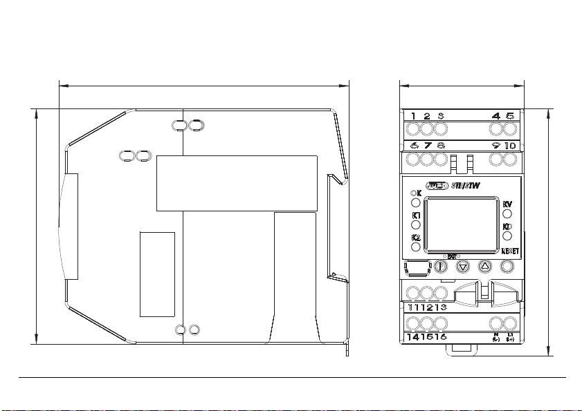
3.1 Dimensions . . . . . . . . . . . . . . . . . . . . . . . . . . . . . . . . . . . . . . . . . . . . . . . . . . . . . . . . . . . . . . . . . . . . . . .17
3.2 Installation location, DIN rail installation. . . . . . . . . . . . . . . . . . . . . . . . . . . . . . . . . . . . . . . . . . . . . . . . .18
3.3 Close mounting. . . . . . . . . . . . . . . . . . . . . . . . . . . . . . . . . . . . . . . . . . . . . . . . . . . . . . . . . . . . . . . . . . . .18
3.4 Dismantling . . . . . . . . . . . . . . . . . . . . . . . . . . . . . . . . . . . . . . . . . . . . . . . . . . . . . . . . . . . . . . . . . . . . . . .19
3.5 Electrical isolation. . . . . . . . . . . . . . . . . . . . . . . . . . . . . . . . . . . . . . . . . . . . . . . . . . . . . . . . . . . . . . . . . .20
3.6 Use of the setup interface . . . . . . . . . . . . . . . . . . . . . . . . . . . . . . . . . . . . . . . . . . . . . . . . . . . . . . . . . . .20
4 Electrical connection . . . . . . . . . . . . . . . . . . . . . . . . . . . . . . . . . . . . . . . . . . . . . . . . . . . . . . . . 21
4.1 Installation notes. . . . . . . . . . . . . . . . . . . . . . . . . . . . . . . . . . . . . . . . . . . . . . . . . . . . . . . . . . . . . . . . . . .21
4.2 Connection diagram . . . . . . . . . . . . . . . . . . . . . . . . . . . . . . . . . . . . . . . . . . . . . . . . . . . . . . . . . . . . . . . .23
5 Commissioning the device . . . . . . . . . . . . . . . . . . . . . . . . . . . . . . . . . . . . . . . . . . . . . . . . . . . . 27
5.1 Display and operating elements . . . . . . . . . . . . . . . . . . . . . . . . . . . . . . . . . . . . . . . . . . . . . . . . . . . . . . .27
5.2 Setting the display after switch-on . . . . . . . . . . . . . . . . . . . . . . . . . . . . . . . . . . . . . . . . . . . . . . . . . . . . .27
Inhalt
Page 4

Inhalt
5.3 Selecting and editing parameters (plausibility inquiry for input values) . . . . . . . . . . . . . . . . . . . . . . . . .29
5.4 Aborting edit . . . . . . . . . . . . . . . . . . . . . . . . . . . . . . . . . . . . . . . . . . . . . . . . . . . . . . . . . . . . . . . . . . . . . .30
5.5 Alarm acknowledgement using the Reset key (only for temperature limiters STB) . . . . . . . . . . . . . . . .30
5.6 Alarm acknowledgement via binary input (only for temperature limiters STB). . . . . . . . . . . . . . . . . . . .30
5.7 Lead sealing the device . . . . . . . . . . . . . . . . . . . . . . . . . . . . . . . . . . . . . . . . . . . . . . . . . . . . . . . . . . . . .31
6 Safety Manual . . . . . . . . . . . . . . . . . . . . . . . . . . . . . . . . . . . . . . . . . . . . . . . . . . . . . . . . . . . . . . 32
6.1 Brief description . . . . . . . . . . . . . . . . . . . . . . . . . . . . . . . . . . . . . . . . . . . . . . . . . . . . . . . . . . . . . . . . . . .32
6.2 Safety temperature monitor (STW) . . . . . . . . . . . . . . . . . . . . . . . . . . . . . . . . . . . . . . . . . . . . . . . . . . . . .32
6.2.1 Safe operating status STW . . . . . . . . . . . . . . . . . . . . . . . . . . . . . . . . . . . . . . . . . . . . . . . . . . . . . . . . . . . . . . . . . . . . . .32
6.3 Safety temperature limiter (STB). . . . . . . . . . . . . . . . . . . . . . . . . . . . . . . . . . . . . . . . . . . . . . . . . . . . . . .33
6.3.1 Safe operating status STB . . . . . . . . . . . . . . . . . . . . . . . . . . . . . . . . . . . . . . . . . . . . . . . . . . . . . . . . . . . . . . . . . . . . . .33
6.4 Relevant standards. . . . . . . . . . . . . . . . . . . . . . . . . . . . . . . . . . . . . . . . . . . . . . . . . . . . . . . . . . . . . . . . .33
6.5 Validity of the Safety Manual . . . . . . . . . . . . . . . . . . . . . . . . . . . . . . . . . . . . . . . . . . . . . . . . . . . . . . . . .34
6.6 Connection possibilities of the sensors (SIL) . . . . . . . . . . . . . . . . . . . . . . . . . . . . . . . . . . . . . . . . . . . . .34
6.7 Standards and definitions. . . . . . . . . . . . . . . . . . . . . . . . . . . . . . . . . . . . . . . . . . . . . . . . . . . . . . . . . . . .37
6.7.1 Terms and abbreviations acc. to DIN EN 14597 . . . . . . . . . . . . . . . . . . . . . . . . . . . . . . . . . . . . . . . . . . . . . . . . . . . . . .37
6.7.2 Terms and abbreviations acc. to DIN EN 61 508 and DIN EN 61 511. . . . . . . . . . . . . . . . . . . . . . . . . . . . . . . . . . . . . . 38
6.8 Safety instrumented parameters related to the temperature monitoring unit . . . . . . . . . . . . . . . . . . . .41
6.8.1 Failure rates and SFF for 701150...23 (AC 230 V) . . . . . . . . . . . . . . . . . . . . . . . . . . . . . . . . . . . . . . . . . . . . . . . . . . . . .41
6.8.2 Failure rates and SFF for 701150...25 (AC/DC 24 V) . . . . . . . . . . . . . . . . . . . . . . . . . . . . . . . . . . . . . . . . . . . . . . . . . . .42
6.9 Determining the Safety Integrity Level (SIL) . . . . . . . . . . . . . . . . . . . . . . . . . . . . . . . . . . . . . . . . . . . . . .43
6.9.1 Safety integrity of the hardware . . . . . . . . . . . . . . . . . . . . . . . . . . . . . . . . . . . . . . . . . . . . . . . . . . . . . . . . . . . . . . . . . . 45
6.9.2 Safety-relevant system properties . . . . . . . . . . . . . . . . . . . . . . . . . . . . . . . . . . . . . . . . . . . . . . . . . . . . . . . . . . . . . . . .46
6.10 Determining the achieved Performance Level PL. . . . . . . . . . . . . . . . . . . . . . . . . . . . . . . . . . . . . . . . . .48
Page 5

6.10.1 Terms and abbreviations acc. to DIN EN ISO 13849 . . . . . . . . . . . . . . . . . . . . . . . . . . . . . . . . . . . . . . . . . . . . . . . . . .48
6.11 Connection possibilities of the sensors (PL). . . . . . . . . . . . . . . . . . . . . . . . . . . . . . . . . . . . . . . . . . . . . .51
6.11.1 Calculations DIN EN ISO 13849-1 Performance Level - low voltage 230 V . . . . . . . . . . . . . . . . . . . . . . . . . . . . . . . . .53
6.11.2 Calculations DIN EN ISO 13849-1 Performance Level - extra low voltage (ELV) 24 V . . . . . . . . . . . . . . . . . . . . . . . . .53
6.11.3 Contribution to risk minimization through the control system . . . . . . . . . . . . . . . . . . . . . . . . . . . . . . . . . . . . . . . . . . .54
6.12 Evaluating the achieved Performance Level PL and the relationship to the SIL . . . . . . . . . . . . . . . . . .56
6.13 Other applicable device documentation. . . . . . . . . . . . . . . . . . . . . . . . . . . . . . . . . . . . . . . . . . . . . . . . .59
6.14 Behavior during operation and in case of malfunction. . . . . . . . . . . . . . . . . . . . . . . . . . . . . . . . . . . . . .59
6.15 Regular tests. . . . . . . . . . . . . . . . . . . . . . . . . . . . . . . . . . . . . . . . . . . . . . . . . . . . . . . . . . . . . . . . . . . . . .59
6.15.1 Recommended tests for temperature probes . . . . . . . . . . . . . . . . . . . . . . . . . . . . . . . . . . . . . . . . . . . . . . . . . . . . . . . .59
6.16 Certificates . . . . . . . . . . . . . . . . . . . . . . . . . . . . . . . . . . . . . . . . . . . . . . . . . . . . . . . . . . . . . . . . . . . . . . .61
7 Configuration level . . . . . . . . . . . . . . . . . . . . . . . . . . . . . . . . . . . . . . . . . . . . . . . . . . . . . . . . . . 70
7.1 Navigation principle . . . . . . . . . . . . . . . . . . . . . . . . . . . . . . . . . . . . . . . . . . . . . . . . . . . . . . . . . . . . . . . .70
7.2 Analog inputs . . . . . . . . . . . . . . . . . . . . . . . . . . . . . . . . . . . . . . . . . . . . . . . . . . . . . . . . . . . . . . . . . . . . .71
7.2.1 Connection . . . . . . . . . . . . . . . . . . . . . . . . . . . . . . . . . . . . . . . . . . . . . . . . . . . . . . . . . . . . . . . . . . . . . . . . . . . . . . . . . .71
7.2.2 Sensor type 1 . . . . . . . . . . . . . . . . . . . . . . . . . . . . . . . . . . . . . . . . . . . . . . . . . . . . . . . . . . . . . . . . . . . . . . . . . . . . . . . .72
7.2.3 Offset 1 . . . . . . . . . . . . . . . . . . . . . . . . . . . . . . . . . . . . . . . . . . . . . . . . . . . . . . . . . . . . . . . . . . . . . . . . . . . . . . . . . . . . .73
7.2.4 Lead wire resistance 1 . . . . . . . . . . . . . . . . . . . . . . . . . . . . . . . . . . . . . . . . . . . . . . . . . . . . . . . . . . . . . . . . . . . . . . . . .73
7.2.5 Filter time 1 . . . . . . . . . . . . . . . . . . . . . . . . . . . . . . . . . . . . . . . . . . . . . . . . . . . . . . . . . . . . . . . . . . . . . . . . . . . . . . . . . .73
7.2.6 Scaling start 1 . . . . . . . . . . . . . . . . . . . . . . . . . . . . . . . . . . . . . . . . . . . . . . . . . . . . . . . . . . . . . . . . . . . . . . . . . . . . . . . .73
7.2.7 Scaling end 1 . . . . . . . . . . . . . . . . . . . . . . . . . . . . . . . . . . . . . . . . . . . . . . . . . . . . . . . . . . . . . . . . . . . . . . . . . . . . . . . . .73
7.2.8 Sensor type 2 . . . . . . . . . . . . . . . . . . . . . . . . . . . . . . . . . . . . . . . . . . . . . . . . . . . . . . . . . . . . . . . . . . . . . . . . . . . . . . . .74
7.2.9 Offset 2 . . . . . . . . . . . . . . . . . . . . . . . . . . . . . . . . . . . . . . . . . . . . . . . . . . . . . . . . . . . . . . . . . . . . . . . . . . . . . . . . . . . . .75
7.2.10 Lead wire resistance 2 . . . . . . . . . . . . . . . . . . . . . . . . . . . . . . . . . . . . . . . . . . . . . . . . . . . . . . . . . . . . . . . . . . . . . . . . .75
Inhalt
Page 6

Inhalt
7.2.11 Filter time 2 . . . . . . . . . . . . . . . . . . . . . . . . . . . . . . . . . . . . . . . . . . . . . . . . . . . . . . . . . . . . . . . . . . . . . . . . . . . . . . . . . . 75
7.2.12 Scaling start 2 . . . . . . . . . . . . . . . . . . . . . . . . . . . . . . . . . . . . . . . . . . . . . . . . . . . . . . . . . . . . . . . . . . . . . . . . . . . . . . . .75
7.2.13 Scaling end 2 . . . . . . . . . . . . . . . . . . . . . . . . . . . . . . . . . . . . . . . . . . . . . . . . . . . . . . . . . . . . . . . . . . . . . . . . . . . . . . . . .75
7.3 Limiter/monitor . . . . . . . . . . . . . . . . . . . . . . . . . . . . . . . . . . . . . . . . . . . . . . . . . . . . . . . . . . . . . . . . . . . .76
7.3.1 Device function . . . . . . . . . . . . . . . . . . . . . . . . . . . . . . . . . . . . . . . . . . . . . . . . . . . . . . . . . . . . . . . . . . . . . . . . . . . . . . .76
7.3.2 Switching behavior . . . . . . . . . . . . . . . . . . . . . . . . . . . . . . . . . . . . . . . . . . . . . . . . . . . . . . . . . . . . . . . . . . . . . . . . . . . .77
7.3.3 Limit value, hysteresis . . . . . . . . . . . . . . . . . . . . . . . . . . . . . . . . . . . . . . . . . . . . . . . . . . . . . . . . . . . . . . . . . . . . . . . . . .79
7.3.4 Pre-alarm function . . . . . . . . . . . . . . . . . . . . . . . . . . . . . . . . . . . . . . . . . . . . . . . . . . . . . . . . . . . . . . . . . . . . . . . . . . . . .79
7.3.5 Pre-alarm, hysteresis . . . . . . . . . . . . . . . . . . . . . . . . . . . . . . . . . . . . . . . . . . . . . . . . . . . . . . . . . . . . . . . . . . . . . . . . . . .79
7.3.6 Limit value difference, hysteresis . . . . . . . . . . . . . . . . . . . . . . . . . . . . . . . . . . . . . . . . . . . . . . . . . . . . . . . . . . . . . . . . .80
7.3.7 Setting range min. (formerly ALHI) . . . . . . . . . . . . . . . . . . . . . . . . . . . . . . . . . . . . . . . . . . . . . . . . . . . . . . . . . . . . . . . 80
7.3.8 Setting range max. (formerly ALLO) . . . . . . . . . . . . . . . . . . . . . . . . . . . . . . . . . . . . . . . . . . . . . . . . . . . . . . . . . . . . . .80
7.4 Binary input. . . . . . . . . . . . . . . . . . . . . . . . . . . . . . . . . . . . . . . . . . . . . . . . . . . . . . . . . . . . . . . . . . . . . . .81
7.4.1 Function . . . . . . . . . . . . . . . . . . . . . . . . . . . . . . . . . . . . . . . . . . . . . . . . . . . . . . . . . . . . . . . . . . . . . . . . . . . . . . . . . . . . .81
7.5 Analog output . . . . . . . . . . . . . . . . . . . . . . . . . . . . . . . . . . . . . . . . . . . . . . . . . . . . . . . . . . . . . . . . . . . . .82
7.5.1 Function . . . . . . . . . . . . . . . . . . . . . . . . . . . . . . . . . . . . . . . . . . . . . . . . . . . . . . . . . . . . . . . . . . . . . . . . . . . . . . . . . . . . .82
7.5.2 Signal type . . . . . . . . . . . . . . . . . . . . . . . . . . . . . . . . . . . . . . . . . . . . . . . . . . . . . . . . . . . . . . . . . . . . . . . . . . . . . . . . . . .82
7.5.3 Scaling start . . . . . . . . . . . . . . . . . . . . . . . . . . . . . . . . . . . . . . . . . . . . . . . . . . . . . . . . . . . . . . . . . . . . . . . . . . . . . . . . .82
7.5.4 Scaling end . . . . . . . . . . . . . . . . . . . . . . . . . . . . . . . . . . . . . . . . . . . . . . . . . . . . . . . . . . . . . . . . . . . . . . . . . . . . . . . . . .82
7.5.5 Error signal . . . . . . . . . . . . . . . . . . . . . . . . . . . . . . . . . . . . . . . . . . . . . . . . . . . . . . . . . . . . . . . . . . . . . . . . . . . . . . . . . .83
7.5.6 Behavior when leaving the scaling range . . . . . . . . . . . . . . . . . . . . . . . . . . . . . . . . . . . . . . . . . . . . . . . . . . . . . . . . . . .84
7.6 Display/operation . . . . . . . . . . . . . . . . . . . . . . . . . . . . . . . . . . . . . . . . . . . . . . . . . . . . . . . . . . . . . . . . . .85
7.6.1 Language . . . . . . . . . . . . . . . . . . . . . . . . . . . . . . . . . . . . . . . . . . . . . . . . . . . . . . . . . . . . . . . . . . . . . . . . . . . . . . . . . . . .85
7.6.2 Unit . . . . . . . . . . . . . . . . . . . . . . . . . . . . . . . . . . . . . . . . . . . . . . . . . . . . . . . . . . . . . . . . . . . . . . . . . . . . . . . . . . . . . . . .85
7.6.3 Decimal place . . . . . . . . . . . . . . . . . . . . . . . . . . . . . . . . . . . . . . . . . . . . . . . . . . . . . . . . . . . . . . . . . . . . . . . . . . . . . . . .85
Page 7

7.6.4 Normal display . . . . . . . . . . . . . . . . . . . . . . . . . . . . . . . . . . . . . . . . . . . . . . . . . . . . . . . . . . . . . . . . . . . . . . . . . . . . . . .85
7.6.5 Contrast . . . . . . . . . . . . . . . . . . . . . . . . . . . . . . . . . . . . . . . . . . . . . . . . . . . . . . . . . . . . . . . . . . . . . . . . . . . . . . . . . . . . .86
7.6.6 Lighting . . . . . . . . . . . . . . . . . . . . . . . . . . . . . . . . . . . . . . . . . . . . . . . . . . . . . . . . . . . . . . . . . . . . . . . . . . . . . . . . . . . . .86
7.6.7 Time-out light . . . . . . . . . . . . . . . . . . . . . . . . . . . . . . . . . . . . . . . . . . . . . . . . . . . . . . . . . . . . . . . . . . . . . . . . . . . . . . . .86
7.6.8 Time-out operation . . . . . . . . . . . . . . . . . . . . . . . . . . . . . . . . . . . . . . . . . . . . . . . . . . . . . . . . . . . . . . . . . . . . . . . . . . . . 86
7.6.9 Code . . . . . . . . . . . . . . . . . . . . . . . . . . . . . . . . . . . . . . . . . . . . . . . . . . . . . . . . . . . . . . . . . . . . . . . . . . . . . . . . . . . . . . .86
7.7 Service . . . . . . . . . . . . . . . . . . . . . . . . . . . . . . . . . . . . . . . . . . . . . . . . . . . . . . . . . . . . . . . . . . . . . . . . . .87
7.7.1 Limit switching cycle . . . . . . . . . . . . . . . . . . . . . . . . . . . . . . . . . . . . . . . . . . . . . . . . . . . . . . . . . . . . . . . . . . . . . . . . . . .87
7.7.2 Current switching cycles . . . . . . . . . . . . . . . . . . . . . . . . . . . . . . . . . . . . . . . . . . . . . . . . . . . . . . . . . . . . . . . . . . . . . . . .87
7.7.3 Operating hours . . . . . . . . . . . . . . . . . . . . . . . . . . . . . . . . . . . . . . . . . . . . . . . . . . . . . . . . . . . . . . . . . . . . . . . . . . . . . . .87
8 Technical data . . . . . . . . . . . . . . . . . . . . . . . . . . . . . . . . . . . . . . . . . . . . . . . . . . . . . . . . . . . . . . 88
8.1 Analog inputs . . . . . . . . . . . . . . . . . . . . . . . . . . . . . . . . . . . . . . . . . . . . . . . . . . . . . . . . . . . . . . . . . . . . .88
8.2 Analog output . . . . . . . . . . . . . . . . . . . . . . . . . . . . . . . . . . . . . . . . . . . . . . . . . . . . . . . . . . . . . . . . . . . . .90
8.3 Binary input. . . . . . . . . . . . . . . . . . . . . . . . . . . . . . . . . . . . . . . . . . . . . . . . . . . . . . . . . . . . . . . . . . . . . . .90
8.4 Relay outputs . . . . . . . . . . . . . . . . . . . . . . . . . . . . . . . . . . . . . . . . . . . . . . . . . . . . . . . . . . . . . . . . . . . . .90
8.5 Measuring circuit monitoring . . . . . . . . . . . . . . . . . . . . . . . . . . . . . . . . . . . . . . . . . . . . . . . . . . . . . . . . .91
8.6 Voltage supply . . . . . . . . . . . . . . . . . . . . . . . . . . . . . . . . . . . . . . . . . . . . . . . . . . . . . . . . . . . . . . . . . . . .91
8.7 Test voltages according to EN 60730, part 1 . . . . . . . . . . . . . . . . . . . . . . . . . . . . . . . . . . . . . . . . . . . . .92
8.8 Electrical safety. . . . . . . . . . . . . . . . . . . . . . . . . . . . . . . . . . . . . . . . . . . . . . . . . . . . . . . . . . . . . . . . . . . .92
8.9 Environmental influences . . . . . . . . . . . . . . . . . . . . . . . . . . . . . . . . . . . . . . . . . . . . . . . . . . . . . . . . . . . .92
8.10 Case . . . . . . . . . . . . . . . . . . . . . . . . . . . . . . . . . . . . . . . . . . . . . . . . . . . . . . . . . . . . . . . . . . . . . . . . . . . .93
8.11 Approvals/approval marks . . . . . . . . . . . . . . . . . . . . . . . . . . . . . . . . . . . . . . . . . . . . . . . . . . . . . . . . . . .94
8.12 Probes for the operating medium air . . . . . . . . . . . . . . . . . . . . . . . . . . . . . . . . . . . . . . . . . . . . . . . . . . .95
8.13 Probes for the operating medium water and oil . . . . . . . . . . . . . . . . . . . . . . . . . . . . . . . . . . . . . . . . . . .96
Inhalt
Page 8

Inhalt
8.14 Probes for the operating medium water, oil and air . . . . . . . . . . . . . . . . . . . . . . . . . . . . . . . . . . . . . . . .98
9 Setup program . . . . . . . . . . . . . . . . . . . . . . . . . . . . . . . . . . . . . . . . . . . . . . . . . . . . . . . . . . . . . 99
9.1 Minimum hardware and software prerequisites: . . . . . . . . . . . . . . . . . . . . . . . . . . . . . . . . . . . . . . . . . .99
9.2 Displaying the device software version . . . . . . . . . . . . . . . . . . . . . . . . . . . . . . . . . . . . . . . . . . . . . . . . .99
9.3 Forgotten the code? . . . . . . . . . . . . . . . . . . . . . . . . . . . . . . . . . . . . . . . . . . . . . . . . . . . . . . . . . . . . . . .100
9.4 Special function: thermocouple reverse polarity protection. . . . . . . . . . . . . . . . . . . . . . . . . . . . . . . . .100
10 Alarm messages . . . . . . . . . . . . . . . . . . . . . . . . . . . . . . . . . . . . . . . . . . . . . . . . . . . . . . . . . . . 101
11 Error messages . . . . . . . . . . . . . . . . . . . . . . . . . . . . . . . . . . . . . . . . . . . . . . . . . . . . . . . . . . . . 102
12 What to do, if ... . . . . . . . . . . . . . . . . . . . . . . . . . . . . . . . . . . . . . . . . . . . . . . . . . . . . . . . . . . . . 107
13 Information for devices with extra code 062 GL . . . . . . . . . . . . . . . . . . . . . . . . . . . . . . . . . 109
13.1 Technical data . . . . . . . . . . . . . . . . . . . . . . . . . . . . . . . . . . . . . . . . . . . . . . . . . . . . . . . . . . . . . . . . . . .109
13.2 Alarm messages . . . . . . . . . . . . . . . . . . . . . . . . . . . . . . . . . . . . . . . . . . . . . . . . . . . . . . . . . . . . . . . . . .109
13.3 Locks . . . . . . . . . . . . . . . . . . . . . . . . . . . . . . . . . . . . . . . . . . . . . . . . . . . . . . . . . . . . . . . . . . . . . . . . . .109
14 Output behavior . . . . . . . . . . . . . . . . . . . . . . . . . . . . . . . . . . . . . . . . . . . . . . . . . . . . . . . . . . . 111
Page 9

Page 10

2014-05-01
1 Brief description
10
1 Brief description
The safety temperature limiter (STB) and the safety temperature monitor (STW) are used to reliably detect and avert hazards
that could cause injuries, are harmful to the environment or cause destruction of production plants and produced goods, at an
early stage.
Its primary task is to reliably monitor thermal processes and switch the systems to an operationally safe status in the event of
malfunctions.
The measured value at the analog input can be recorded by various probes or standard signals.
The limit value overrange is indicated by the installed LEDs K1 and K2 (red) for each channel, and the installed relay "Alarm"
switches the system to an operationally safe status (alarm range).
The high standards of DIN EN 61508 and DIN EN ISO 13849 are met by a device design, the 1oo2D structure of which ensures
reliable detection of errors and, thus, can also be used for applications according to the new Machinery Directive 2006/42/EC.
1.1 Safety temperature monitor (STW)
The STW is a safety component according to Machinery Directive, which, when activated, resets automatically if the probe
temperature has gone below / exceeded the limit value by an amount equal to the hysteresis. Possible settings: monitoring for
limit value overrange or underrange.
v Chapter 7.3.2 "Switching behavior"
1.2 Safety temperature limiter (STB)
The STB is a safety component according to Machinery Directive that is permanently locked after response. Manual reset using
the key is only possible once the probe temperature has gone below / exceeded the limit value by an amount equal to the
hysteresis. Possible settings: monitoring for limit value overrange or underrange.
v Chapter 7.3.2 "Switching behavior"
The transparent cover can be lead sealed to prevent unauthorized operation.
However, the key remains accessible.
Page 11
1.3 Safety information
H
A
V
Symbol Meaning Explanation
Note This symbol is used to draw your attention to important information.
Caution This symbol is used when there is a risk of damage to equipment or data if the instructions are ig-
Danger This symbol is used when there is a risk of injury to persons if the instructions are ignored or not
Read This text contains important information and must always be read before work is continued. Han-
v Reference This symbol refers to further information in other manuals, chapters or sections.
1
abc
*
2014-05-01
Footnote Footnotes are remarks referring to specific points in the text marked with a superscript number.
Instructions
for action
nored or not followed correctly.
followed correctly.
dling the device in any way that is not described in the Operating Manual or that is expressly forbidden will jeopardize your warranty rights.
This symbol indicates that an action to be performed is described. The individual steps are marked
by an asterisk.
1 Brief description
11
Page 12
2014-05-01
A
Voltage supply AC 110 to 240 V:
Voltage supply AC/DC20 to 30 V:
Switching behavior
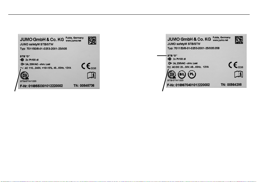
2 Identifying the device version
The type plate is affixed to the side of the device.
The voltage supply must correspond to the voltage given on the type plate!
2 Identifying the device version
12
Page 13

Basic type
701150 Safety temperature limiters (STB) / monitors (STW) according to DIN EN 14597
Ver sion
8 Factory setting
9 Configured according to customer specifications
01 German (factory setting)
02 English
03 French
0251 Safety temperature monitor max. alarm (inverse, N/C contact)
0252 Safety temperature monitor min. alarm (direct, N/O contact)
0253 Safety temperature limiter max. alarm (inverse, N/C contact)
0254 Safety temperature limiter min. alarm (direct, N/O contact)
1003 1x Pt100 in 2-wire circuit
2001 2x Pt100 in 3-wire circuit (ex-factory)
2003 2x Pt100 in 2-wire circuit
2006 2x Pt1000 in 3-wire circuit
2037 2x W3Re-W25Re "D"
2039 2x Cu-CuNi "T"
2040 2x Fe-CuNi "J"
2041 2x Cu-CuNi "U"
2042 2x Fe-CuNi "L"
2043 2x NiCr-Ni "K"
Language
Switching behavior
Measuring input1 (programmable)
2014-05-01
2 Identifying the device version
13
Page 14

2014-05-01
2044 2x Pt10Rh-Pt "S"
2045 2x Pt13Rh-Pt "R"
2046 2x Pt30Rh-Pt6Rh "B"
2048 2x NiCrSi-NiSi "N"
1053 1x 4 to 20 mA
2053 2x 4 to 20 mA
23 AC 110 to 240 V +10 % /-15 %, 48 to 63 Hz
25 20 to 30 V AC/DC, 48 to 63 Hz
701150 / 8 - 01 - 0253 - 2001 - 23 / 005 , 062
1. The first number on the measuring input means single probe "1“ or double probe "2“
2 Identifying the device version
Voltage supply
Analog output (configurable)
001 0 to 20 mA
005 4 to 20 mA (ex-factory)
040 0 to 10 V
070 2 to 10 V
Extra code
2.1 Scope of delivery
-JUMO safetyM STB/STW in the version ordered
- Operating Manual B701150.0
058 SIL and PL approval
062 GL approval
14
Page 15
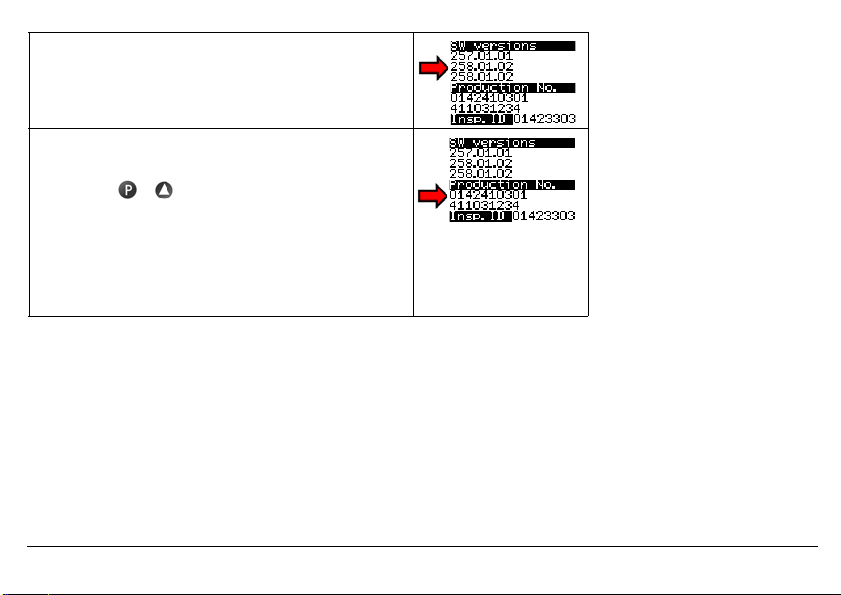
2.2 Device software versions
Diagnosis module version: 257.01.01
Analog channel 1 version: 258.01.02
Analog channel 2 version: 258.01.02
2.3 Serial number
The serial number is indicated on the device.
h Press the + keys
Construction:
The first 8 digits specify the serial number: 01424103
Digit 9 and 10 the production plant in Fulda: 01
Digit 11 (second line) the hardware version: 4
Digit 12 and 13 the year: 2011
Digit 14 and 15 the calendar week: 03
Digit 16 to 19 consecutive numbers: 1234
2.4 Service addresses
Phone support in Germany:
Telephone:+49 661 6003-9135
Fax: +49 661 6003-881899
Email: service@jumo.net
2014-05-01
Austria:
Telephone:+43 1 610610
Fax: +43 1 6106140
Email: info@jumo.at
Switzerland:
Telephone:+41 44 928 24 44
Fax: +41 44 928 24 48
Email: info@jumo.ch
2 Identifying the device version
15
Page 16

2014-05-01
A
2 Identifying the device version
This operating manual is a translation of the German original manual.
It is valid for the following hardware and software versions:
Diagnosis module from version: 257.01.01
Analog channel 1 from version: 258.01.02
Analog channel 2 from version: 258.01.02
Hardware version: 0
16
h Press the + keys
Keep the operating manual in a place accessible to all users at all times.
All necessary settings are described in this Operating Manual.
Handling the device in any way that is not described in the Operating Manual or that is expressly forbidden will
jeopardize your warranty rights and may disable the safety function.
It is forbidden to access the inside of the device!
Repairs may only be performed by JUMO at the head office in Fulda.
Please contact the nearest subsidiary or the head office should you encounter any problems.
Page 17
3 Installation
45
89 4,
85
104 8,
3.1 Dimensions
2014-05-01
3 Installation
17
Page 18

2014-05-01
V
3.2 Installation location, DIN rail installation
The device is not suitable for use in potentially explosive atmospheres.
The device is hooked into a 35 mm DIN rail (EN 60715) from the front and
pushed down to engage.
The ambient conditions at the installation site must meet the requirements
v
specified in the technical data.
Chapter 8 "Technical data"
As far as possible, the installation site should be vibration-free to prevent the screw-connections from working loose.
a
The installation site should be free from aggressive media, e.g. acids and lyes, and, if possible, free from dust, flour or
a
other suspended matter in order to prevent the cooling slots from becoming clogged.
3.3 Close mounting
Observe a minimum spacing of 20 mm from the top and bottom.
a
1. To allow the release slot to be accessed with a screwdriver from below.
2. To allow the device to be swiveled up and unhooked from the DIN rail for removal.
Several devices may be mounted side by side without a gap.
a
3 Installation
18
Page 19
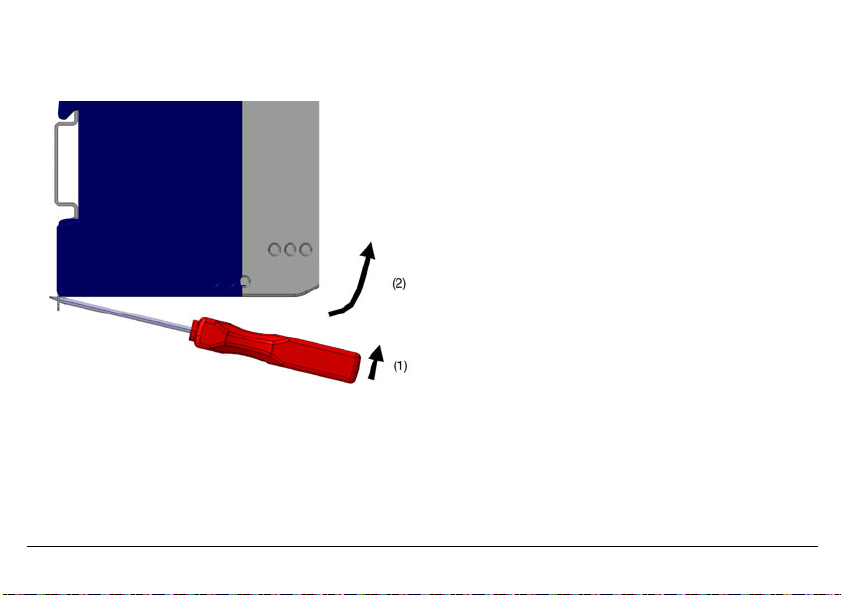
3.4 Dismantling
h Insert a screwdriver into the release lug from below and lift up (1).
h Simultaneously swivel the screwdriver and case up out of the DIN rail (2).
2014-05-01
3 Installation
19
Page 20
2014-05-01
»
3700 V AC
»
3700 V AC
(1)
(2)
(4)
(3)
(5)
(8)
(6)
(7)
»
3700 V AC
50 V DC
»
3.5 Electrical isolation
3 Installation
20
(1) Analog inputs
(3) Binary input
(5) Setup interface
(6) Display
(7) Analog output
3.6 Use of the setup interface
- The setup interface USB is only designed for service use for a limited period, e.g. for transmitting setup data and during
- It is not suitable for operation in a fixed installation for an unlimited period as the monitoring function is switched off during
(8) Power supply
commissioning.
data transmission with the setup program.
(2) Relay output "Alarm"
(4) Relay output "Pre-alarm"
Page 21

4 Electrical connection
V
4.1 Installation notes
Check that the safety temperature limiter is correctly installed for its application (temperature measurement) and is oper-
a
ated within the admissible system parameters.
The device is designed for installation in switch cabinets, machines/plants or systems.
a
Ensure that the customer's fuse rating does not exceed 20 A.
Isolate the device at all poles prior to starting service or repair work.
a
All incoming and outgoing lines without a connection to the power supply network must be laid with shielded and
a
twisted lines. Connect the screen on the device side to ground.
Do not run input and output lines close to current-carrying components or cables.
a
Do not connect any additional consumers to the screw terminals for the device power supply.
a
The choice of cable, the installation and the electrical connection of the device must conform to the requirements of VDE
a
0100 "Regulations on the Installation of Power Circuits with Nominal Voltages below 1000 V" or the appropriate local
regulations.
Protect the relay circuit by suitable measures.
a
The maximum contact rating is 230 V/3 A (ohmic load).
The electromagnetic compatibility conforms to the standards and regulations cited in the technical data.
a
v Chapter 8 "Technical data"
During commissioning we recommend carrying out a trial run of the system until temperature switch-off at the set limit.
a
Only allow qualified electricians to carry out the electrical connection and the configuration settings until commissioning.
2014-05-01
4 Electrical connection
21
Page 22

2014-05-01
A
4 Electrical connection
The approval according to DIN EN 14597 is only valid when the correct probe with DIN approval is set in the configuration level and also connected.
The limit value to be monitored must be within the admissible temperature range of the DIN probe.
v Chapter 8.12 "Probes for the operating medium air"
v Chapter 8.13 "Probes for the operating medium water and oil"
The monitoring function is deactivated during data transmission using the setup program.
v Chapter 12 "What to do, if ..."
22
Page 23
4.2 Connection diagram
Connection is carried out via screw terminals. Lead Admissible cross sec-
1 wire
fine-strand,
with core-end ferrule
2014-05-01
4 Electrical connection
tion
≤ 2.5 mm
≤ 1.5 mm
2
2
23
Page 24
2014-05-01
V
+
–
2
3
+
–
7
8
J
13
J
68
A
Enter the lead resistance for RTD temperature probes in two-wire circuit when using greater line
lengths.
v Setup program: edit => analog inputs
123
J
678
J
J
13 68
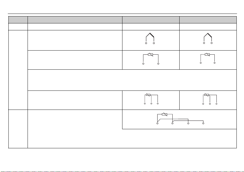
4 Electrical connection
Legend Remark Screw terminals Screw terminals
1, 2 Analog input1 (E1) Analog input2 (E2)
Thermocouple/
double thermocouple
RTD temperature probe Pt100/Pt1000 in
2-wire circuit
RTD temperature probe Pt100/Pt1000
in three-wire circuit
RTD temperature probe Pt100 in
two-wire circuit, individual probe for both analog
inputs
Caution:
When only one probe (SIL2) is connected, the temperature limitation device
is reduced from SIL3 to SIL2. However, the internal 2-channel structure (1oo2D) in the device is still retained.
Both channels measure the same probe due to the simplified external circuit.
24
Page 25
V
V
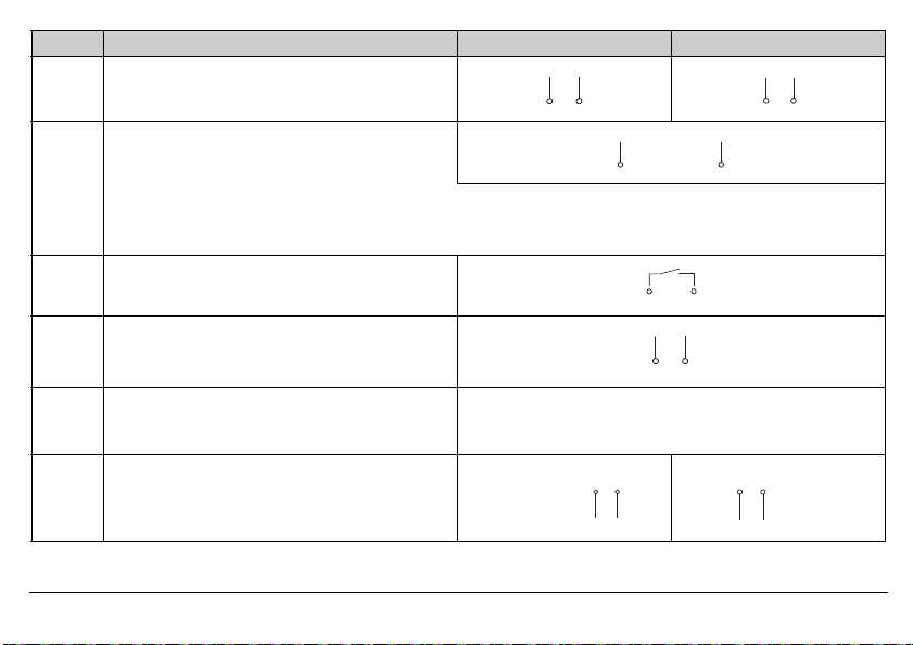
Legend Remark Screw terminals Screw terminals
2
3
+
–
I
x
7
8
+
–
I
x
+
–
I
x
4
5
Ground
9
10
+
–
Ix,U
x
L1 N
L1 N
L+ L-
L+ L-
4 to 20 mA
4 to 20 mA for both analog inputs
Caution:
When only one probe (SIL2) is connected, the temperature limitation device
is reduced from SIL3 to SIL2. However, the internal 2-channel structure (1oo2D) in the device is still retained.
Both channels measure the same current signal due to the simplified external circuit.
4 Binary input
Connection to a potential-free contact
5 Analog output:
0 to 20 mA
4 to 20 mA (ex-factory)
0(2) to 10V
Caution
The analog output is not part of the safety func-
tion!
9 Voltage supply
2014-05-01
according to rating plate
AC:
L1 Line conductor
N Neutral
4 Electrical connection
DC:
(L+)
(L-)
25
Page 26
2014-05-01
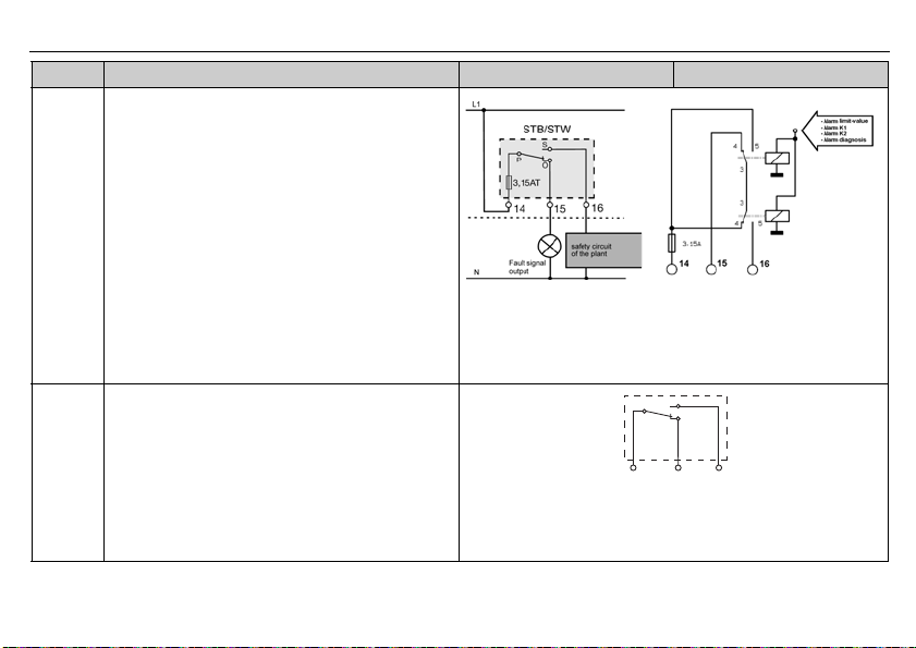
V
Internal
circuitry
S
P
11
12 13
Ö
Legend Remark Screw terminals Screw terminals
10 Relay output "Alarm" (current-free state)
Relay (changeover contact element) with fuse cutout
4 Electrical connection
26
11 Relay output for pre-alarm (KV)
Changeover contact
Caution
The pre-alarm relay output is not part of the
safety function!
Page 27
5 Commissioning the device
H
(1) (2) (3)
(4)
(5)
(6)
(7)
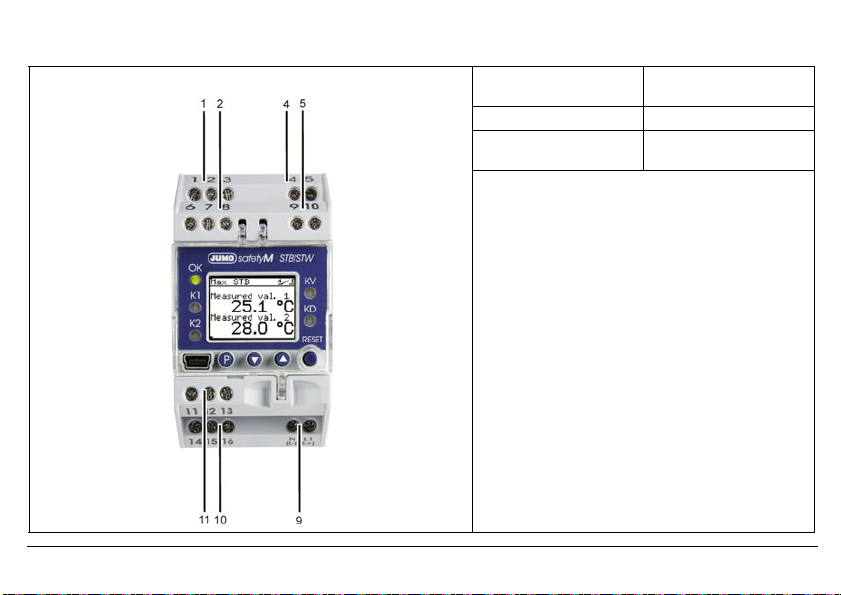
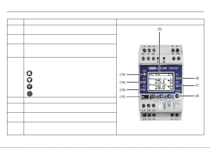
5.1 Display and operating elements
h Connect the voltage supply - a test routine will start during which all LEDS will flash and the display with background light-
ing will indicate white pixels for 2 seconds and black pixels for 2 seconds.
Once the test routine has been completed, the device will indicate the main measured value (factory set).
v If an alarm or error message appears, refer to Chapter 10 "Alarm messages".
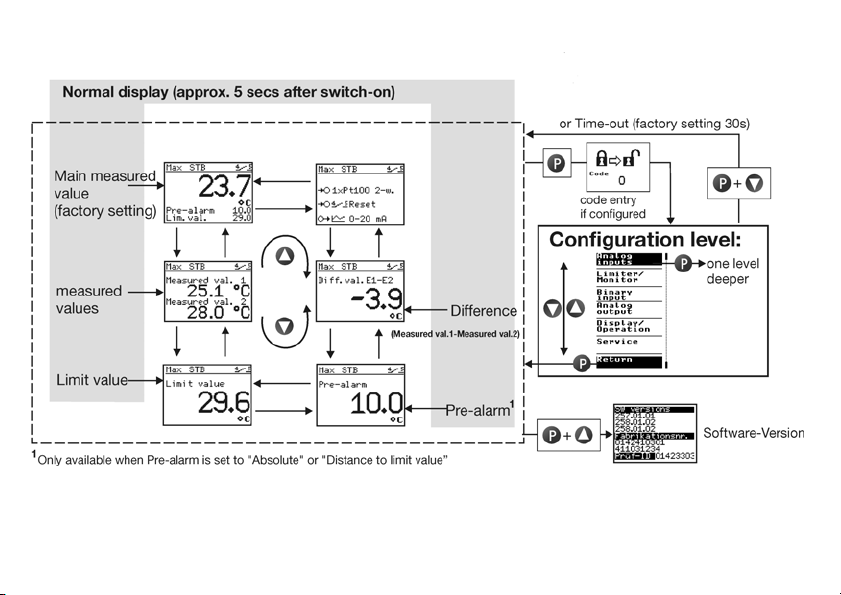
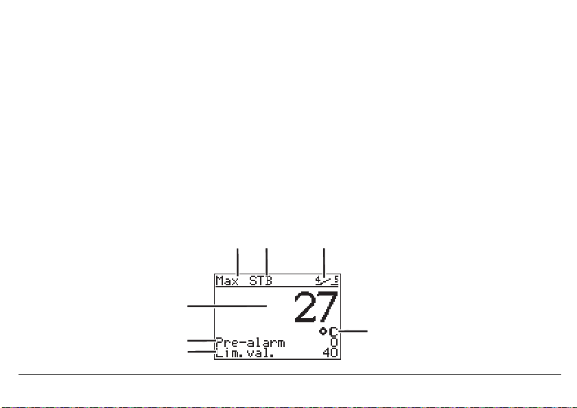
5.2 Setting the display after switch-on
v Chapter 7.6.4 "Normal display"
The screen is factory set to show the main measured value in German. The example shows the screen layout of a safety temperature limiter monitoring a maximum value of 29.6°C with a pre-alarm set to 9.9°C.
If the main measured value is within the hysteresis during "Power ON", the relay outputs "Pre-alarm" and "Alarm"
are deactivated.
1 Switching behavior 2 Device function
3 Binary input
7 Main measured value
6 Pre-alarm 4 Temperature unit
5 Limit value
2014-05-01
5 Commissioning the device
27
Page 28
2014-05-01
Legend Remark
3LCD display
6 LED KV (yellow)
7 LED KD (yellow)
8Keys
12 Setup interface
13 LED K2 (red)
14 LED K1 (red)
15 LED OK
Black and white with background lighting 96 x 64 pixels
Is lit if the pre-alarm was triggered.
Is lit if the diagnosis processor has switched off a component.
(Can only be operated when the transparent hood is folded up)
Increase value / previous parameter
Reduce value / next parameter
Programming
RESET
Is lit for all errors.
Is lit for all errors.
Green: OK range
OFF: Error occurred
5 Commissioning the device
28
Page 29
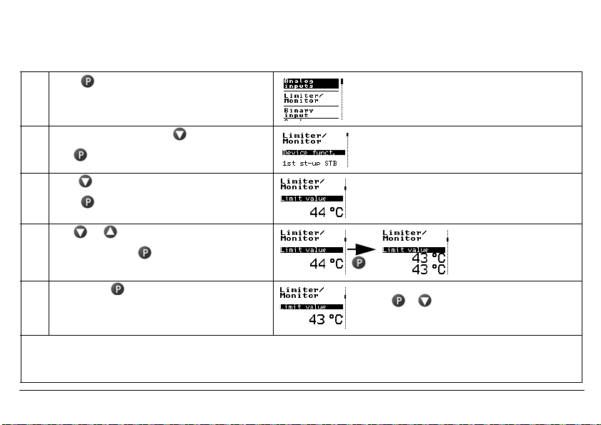
5.3 Selecting and editing parameters (plausibility inquiry for input values)
The values are displayed in the standard display.
Carry out steps 1 to 4 to edit a value, e.g. in this case, the limit value
1 Press The first menu item "Analog inputs" has a black
2 Select limiter/monitor with
Use to change to the submenu
3 Press 2x until the limit value appears
Press (limit value flashes)
background. The vertical line on the right shows
the current position.
4 Use or to set the desired value
Acknowledge with
(limit value is shown in duplicate)
5 Briefly press to confirm the value.
The value is applied and saved.
If no key is pressed, the device automatically returns to the standard display after 30 seconds (timeout) and the value
H
is not saved. The length of the timeout is configurable.
Use + to return to the standard display
or menu topic "Back" or
return automatically after a timeout
Limit value flashes in duplicate on the display as a
control.
v see operating overview on the first inner page of this manual.
2014-05-01
5 Commissioning the device
29
Page 30
2014-05-01
5 Commissioning the device
30
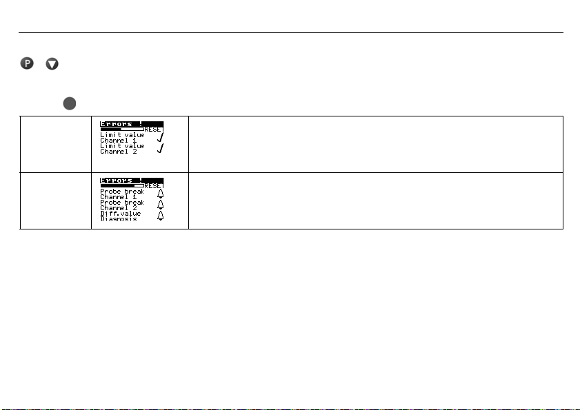
5.4 Aborting edit
+ are used to abort editing and retain the previous value.
5.5 Alarm acknowledgement using the Reset key (only for temperature limiters STB)
h Press key and hold down
Ticks appear
after the errors
A bell is
shown after
the error.
The alarm is no longer pending and is acknowledged as soon as the time bar has finished (3 seconds).
The alarm condition is still pending and cannot be acknowledged.
5.6 Alarm acknowledgement via binary input (only for temperature limiters STB)
The binary input can be configured so that, for example, alarms can be unlocked via a potential-free contact.
The function only reacts to the switching flank from the "open" to the "closed" state.
The contact then behaves in the same way as the "Reset" button.
v Chapter 7.4.1 "Function"
Page 31

5.7 Lead sealing the device
The device settings must not change under operating conditions.
A lead-sealed, transparent cover must therefore be placed over it to prevent unintentional or unauthorized adjustment.
Two holes are provided to the left and right of the transparent cover through which wire
can be guided for lead sealing to connect the cover to the housing. The wire ends are
secured with the lead seal.
2014-05-01
5 Commissioning the device
31
Page 32

2014-05-01
6 Safety Manual
32
6 Safety Manual
6.1 Brief description
The safety temperature limiter (STB) and safety temperature monitor (STW) enable early and reliable detection of risks which
could potentially result in personal injuries, environmental damage, or destruction of the production plant and production materials.
Its task is to reliably monitor process variables such as temperature or pressure and to switch the plants to an operationally
safe status in the event of malfunctions.
The measured value at the analog input can be recorded by various probes or standard signals.
Even when using double sensors (1oo2) only one physical measuring point is monitored at the measuring point.
Limit value exceedance is indicated by the installed LED K1 and K2 (red) for each channel and the integrated alarm relay
switches the system to safe operating status (alarm range).
The SIL3 requirements of DIN EN 61508 or PLe DIN EN ISO 13849 are met by a device concept that has a 1oo2D structure
which ensures reliable detection of errors.
6.2 Safety temperature monitor (STW)
The safety temperature monitor is a device that is automatically reset when activated once the sensor temperature has fallen
below or risen above the set limit value by an amount equal to the switching differential. Possible settings: monitoring for limit
value overrange or underrange.
Mode of operations:
- Minimum requirements: 2B, 2K, 2P
- Additional requirements: 2N, 2D
6.2.1 Safe operating status STW
The safe status is when the relay output alarm between terminals 14 and 16 is switched off (closed-circuit principle).
Page 33

6.3 Safety temperature limiter (STB)
The safety temperature limiter is a device that is permanently locked after responding.
Manual reset using the key is possible once the probe temperature has fallen below / has exceeded the limit value by the
amount of the switching differential. Possible settings: monitoring for overrange or underrange.
Mode of operations:
- Minimum requirements: 2B, 2J, 2V, 2K, 2P and adjustable with special tools
- Additional requirements: 2N, 2F, 2D
6.3.1 Safe operating status STB
The safe status is when the relay output alarm between terminals 14 and 16 is switched off (closed-circuit principle).
This status is maintained until manual unlocking is performed in the valid range of the device.
The transparent, sealable protective cover prevents unauthorized operation.
The key for manual unlocking can be accessed with the aid of a tool.
6.4 Relevant standards
Failure of the devices could affect the safety of persons and/or the safety of the environment.
Certification to IEC 61 508 is provided because of the worldwide use of these systems.
The temperature monitoring unit type 701150 with extra code "058" meets the requirements
- For safety function to SIL3 according to DIN EN 61 508 parts 1 to 7:
Functional Safety - Safety Related Electrical /Electronic / Programmable Electronic Systems
- DIN EN 61 511 Parts 1 to 3:
Functional Safety - Safety-Related Systems for the Process Industry
- DIN EN 14 597:2005-12:
Temperature Regulation Equipment and Temperature Limiter for Heat-Generating Systems
- DIN EN 60 730-2-9:
2014-05-01
6 Safety Manual
33
Page 34

2014-05-01
Automatic Electrical Control and Regulating Devices for Household Use and Similar Applications Parts 2-9: Special Requirements for Temperature-Dependent Control and Regulating Devices
- EN 61 326
- DIN EN ISO 13849-1 PLe
- UL 60730-2-9
- According to the Pressure Equipment Directive
6 Safety Manual
6.5 Validity of the Safety Manual
34
H
The evaluation described in this Safety Manual in terms of functional safety and display of certificates applies to
the specified versions of temperature monitoring units including sensor versions.
Specifications that do not take the sensor system into consideration is identified as such.
6.6 Connection possibilities of the sensors (SIL)
The JUMO safetyM STB/STW 701150 evaluation device structure is basically identical. Various possibilities to connect the
sensors are available. These possibilities are listed in the following table along with the achievable SIL level:
Page 35

Variant Connected sensors
1 1 × Pt100 in 2-wire circuit
1a 2x Pt100/1000 2-wire circuit 1oo2 1oo2D SIL3
2 2x Pt100/1000 3-wire circuit 1oo2 1oo2D SIL3
3 2x thermocouple 1oo2 1oo2D SIL3
4 1x Pt100/1000
5 STB/STW 701150 without
Important information:
Variants 1 to 4 were evaluated with JUMO probes according to data sheets 901006 and 902006. For variant 5 no sensor system was taken into account. In this case, the user selects the sensor system. For this reason, the user is responsible for evaluating the achievable SIL.
If the used SIL-capable sensor consists of hardware and software (e.g. transmitter), the maximum SIL that can be achieved –
irrespective of the architecture – is the one according to which the sensor software was developed (so, for example, if the sensor software has SIL2, the max. achievable SIL is 2).
individual sensor
2-wire and 3-wire circuit
1x thermocouple
sensor system 1oo2D architecture.
No probe or use 4 to 20 mA
(means that the sensor is not
taken into account for the calculation).
Sensor
system
architecture
1oo1 1oo2D SIL2
1oo2 1oo2D SIL3
Sensors connected by the
system user
Architecture
acc. to connection 1oo1
or 1oo2
Logic
architectureAchievable SIL
1oo2D SIL of the used
sensor (HW only)
SIL1 SIL1 SIL2
SIL2 SIL2 SIL3
SIL3 SIL3 SIL3
Max. achievable
SIL of the system
with 1oo1 sensor
system architecture
Max. achievable
SIL of the system with 1oo2
sensor system
architecture
2014-05-01
6 Safety Manual
35
Page 36

2014-05-01
The possibility to connect passive sensors such as double thermocouples, Pt100 sensors, or Pt1000 sensors means that the
sensors do not necessarily require a SIL qualification. In this case, the specification of the failure rates for the passive sensors
is sufficient for the SIL qualification of the overall system. The user of the system must always determine the PFD
PFH value of the overall safety chain to evaluate the achieved SIL
Requirements regarding proof-check interval and lifetime apply only in terms of functional safety.
Requirements as specified by DIN EN 14 597 are defined in the Operating Manual B 701150 and are independent of the re-
quirements of this Safety Manual.
Temperature probe
Admissible measuring ranges must be observed for devices with approval according to DIN EN 14 597 and SIL certification. If
other temperature probes than those described by JUMO data sheets 901006 and 902006 are used, their registration and suitability for use must be verified.
6 Safety Manual
36
and/or
avg
Page 37

6.7 Standards and definitions
6.7.1 Terms and abbreviations acc. to DIN EN 14597
Abbreviation Explanation
Type 2 Mode of operation for which the manufacturing variation and migration of the operating value, operat-
Type B Micro disconnection in operation, corresponding contact disconnection at at least one pole to
Type D A free trip mechanism that also cannot be closed temporarily for as long as the error persists.
Type F (STB) A mode of operation in which, after the RS has been installed, it can only be reset with the aid of a tool.
Type J (STB) A free trip mechanism with contacts that cannot be prevented from opening and which may not func-
Type K A probe mode of operation in which a probe break or a disconnection between the probe head and the
Type N A mode of operation in which the operating value does not increase as a result of a leak in the probe or
Type V (STB) A lockout that can only be reactivated through a manual reset.
Type P A mode of operation that is effective following a specified test through a change in temperature, as
ing duration, or operating procedure has been checked.
provide functional reliability.
tion as an automatically resetting RS if the means of resetting is held in the "Reset" or "On" position.
switching head does not cause the operating value to increase.
in the parts that connect the probe and switching head. This mode is intended for use with electrical error models.
specified in 17.101 of DIN EN 60730-2-9.
2014-05-01
6 Safety Manual
37
Page 38

2014-05-01
6 Safety Manual
38
6.7.2 Terms and abbreviations acc. to DIN EN 61 508 and DIN EN 61 511.
Name Description
Actuator Part of a safety-related system that intervenes in the process to achieve a safe state.
EUC EUC (equipment under control)
E / E / PE Electrical/electronic/programmable electronic (E/E/EP):
Failure End of the ability of a functional unit to perform a required function.
Diagnostic coverage Partial reduction in the probability of dangerous hardware failures due to the use of
Errors A non-normal condition that can cause a reduction or the loss of the ability of a
Functional safety A part of overall safety related to the EUC and EUC control system that depends on the
Functional unit Unit consisting of hardware or software or both that is suitable for performing a
Dangerous failure A failure with the potential of placing the safety-related system in a dangerous state or a
Safe failure A failure without the potential of placing the safety-related system in a dangerous state
Hazard Potential source of damage
Security Absence of unjustifiable risks
Equipment, machine, apparatus, or system used for manufacturing, shaping materials,
for transport, medical purposes, or other activities.
based on electrical (E) and/or electronic (E) and/or programmable electronic (PE)
technology
automatic diagnostic tests.
functional unit to perform a required function.
correct function of the E/E/EP safety-relevant system, safety-relevant systems of other
technology, and external equipment for risk reduction.
specified task.
state without functional capability.
or state without functional capability.
Page 39

Name Description
Safety function A function that is performed by an E / E / PE safety-related system, safety-related
Safety integrity The probability that a safety-related system will perform the required safety function
Safety Integrity Level (SIL) One of four discrete levels for specifying the requirement for safety integrity of the
Safety-related system A system that
Safety Instrument System (SIS) Safety instrumented system to perform one or more safety-related functions. A SIS
λ Failure rate per hour
Lambda:
Lambda dangerous:
Δangerous Δetect: λ
Lambda
Δangerous Υndetect: λ
Lambda
λ
Lambda:
λ
Lambda:
λ
D
S
SD
system based on some other technology, or external equipment for reducing risk with
the goal of achieving or maintaining a safe state for the EUC taking into consideration a
specified dangerous event.
under all specified conditions within a specified period of time according to
requirements.
safety functions assigned to the E/E/PE safety related system. Safety Integrity Level 4
represents the highest level of safety integrity, while Safety Integrity Level 1 represents
the lowest.
- performs necessary safety functions that are required to reach or maintain a safe state
for the EUC and
- is designed by itself or with other E / E / PE safety-related systems of other
technology or external equipment for risk reduction to achieve the necessary safety
integrity for the required safety functions.
consists of sensor(s), logic system, and actuator(s).
Rate of dangerous failures per hour
Rate of detected dangerous failures per hour
DD
Rate of undetected dangerous failures per hour
DU
Rate of safe failures per hour
Rate of detected safe failures per hour
2014-05-01
6 Safety Manual
39
Page 40

2014-05-01
Name Description
Lambda:
λ
SU
BPCS Basic Process Control System
DC Diagnostic Coverage
FIT Failures In Time (1x10
HFT Hardware Fault Tolerance
PFD Probability of Failure on Demand
PFD
avg
MooN Architecture with M from N channels
MTBF Mean Time Between Failures
MTTR Mean Time To Repair
SFF Safe Failure Fraction
SIL Safety Integrity Level
Rate of undetected safe failures per hour
-9
per h)
Average Probability of Failure on Demand
6 Safety Manual
40
Page 41

6.8 Safety instrumented parameters related to the temperature monitoring unit
The following parameters were calculated by means of an FMEDA component under the following conditions:
- Error models corresponding to requirements of DIN EN 61508 for conformity with SIL2 or SIL3
- Failure rate of components according to the RDF 2000 UTE C 80-810 standard and SN 29500
- Sensors were combined as a subsystem in the following five variants:
6.8.1 Failure rates and SFF for 701150...23 (AC 230 V)
λ
Variant
[Fit]
s
1 865.21 306.24 32.31 96 % 4.56 e
1a 865.21 306.24 32.31 96 % 1.05 e
2 868.17 303.28 32.31 96 % 1.05 e
3 881.62 326.78 33.62 96 % 1.03 e
4 887.68 343.82 35.52 96 % 1.22 e
5 881.02 313.43 35.57 96 % 1.04 e
λ
[Fit]
dd
λ
[Fit]
dd
SFF PFH (1/h)
PFD
avg
-9
-9
-9
-9
-9
-9
2.02 e
4.57 e
4.57 e
4.49 e
5.30 e
4.48 e
-4
-5
-5
-5
-5
-5
Important information:
Variants 1 to 4 were evaluated with JUMO probes according to data sheets 901006 and 902006.
For variant 5 no sensor system was taken into account.
In this case, the user selects the sensor system.
2014-05-01
6 Safety Manual
41
Page 42

2014-05-01
6.8.2 Failure rates and SFF for 701150...25 (AC/DC 24 V)
6 Safety Manual
42
Variant
λ
[Fit]
s
λ
[Fit]
dd
λ
[Fit]
dd
SFF
1 799.3 306.32 33.61 96 % 6.59 e-92.91 e
1a 799.3 306.32 33.61 96 % 3.07 e-91.35 e
2 802.26 303.36 33.61 96 % 3.07 e-91.35 e
3 827.25 324.71 37.91 96 % 3.13 e-91.37 e
4 833.31 341.75 39.81 96 % 3.23 e-91.41 e
5 818.96 323.07 36.26 96 % 3.05 e-91.33 e
PFH (1/h)
PFD
avg
-4
-4
-4
-4
-4
-4
Important information:
Variants 1 to 4 were evaluated with JUMO probes according to data sheets 901006 and 902006.
For variant 5 no sensor system was taken into account.
In this case, the user selects the sensor system.
The PFH and PFD
thermore, the calculation was based on a lifetime of 10 years (T
ing to the tables of DIN EN 61508 for sensor systems and logic.
values were calculated with the assumption that the time to restore the system is 8 h (MTTR = 72 h). Fur-
avg
= 10 y). The Common Cause Factor was determined accord-
1
Page 43

6.9 Determining the Safety Integrity Level (SIL)
The achievable Safety Integrity Level is determined by the following safety-related parameters:
- Average probability of dangerous failures of a safety function on demand (PFD
- Hardware Fault Tolerance (HFT) and
- Safe Failure Fraction (SFF).
The specific safety-related parameters for the 701150 measuring system may be found in the table of the "Safety-related parameters" chapter.
The following table shows how the "Safety Integrity Level" (SIL) depends on the "average probability of dangerous failures of a
safety function of the entire safety-related system" (PFD
ered, i. e. the demand rate for the safety-related system averages once a year.
) according to DIN EN 61 508. The "low demand mode" is consid-
avg
Table High Demand PFH
Safety Integrity Level
(SIL)
4
3 ≥10
2 ≥10
1 ≥10
Operating mode with high demand rate
PFH (high demand mode)
≥10
-9
-8
-7
-6
to <10
to <10
to <10
to <10
-8
-7
-6
-5
avg
),
2014-05-01
6 Safety Manual
43
Page 44

2014-05-01
Table Low Demand PFD
Safety Integrity Level
(SIL)
4
3 ≥10
2 ≥10
1 ≥10
Operating mode with low demand rate
(low demand mode)
PFD
av
-5
≥10
-4
-3
-2
to <10
to <10
to <10
to <10
-4
-3
-2
-1
6 Safety Manual
44
The sensor, logic unit, and actuator together form a safety-related system that performs a safety function. The "average probability of dangerous failures of the entire safety-related system" (PFD
tuator subsystems according to the following diagram.
Typical subdivision of the "average probability of dangerous failures of a safety function on demand" (PFD
The specifications related to functional safety in this Safety Manual include sensor systems (resistance temperature sensors,
thermocouples), logic unit (701150), and (as signal contact) the relay output in the 701150 system.
) is usually divided up into the sensor, logic unit, and ac-
avg
) into subsystems
avg
The actuator (for example a power contactor) is system-related and must be taken into consideration separately according to
the standard for the safety loop.
Page 45

6.9.1 Safety integrity of the hardware
According to DIN EN 61 508, a distinction must be made between systems of type A and systems of type B.
A subsystem can be considered to be type A if, for the components required to achieve the safety function,
- the failure behavior of all components used is sufficiently defined; and
- the behavior of the subsystem can be fully determined under failure conditions; and
- reliable failure data from experience in the field exists for the subsystem to show that the assumed failure rates for detected
and undetected dangerous failures are achieved.
A subsystem can be considered to be type B if, for the components required to achieve the safety function,
- the failure behavior of at least one of the components used is not sufficiently defined; or
- the behavior of the subsystem cannot be fully determined under failure conditions; or
- no sufficiently reliable failure data from experience in the field exists for the subsystem to support the utilized failure rates
for detected and undetected dangerous failures.
The 701150 temperature monitoring unit corresponds to a type B system.
The following table shows the achievable Safety Integrity Level (SIL) in dependency on the proportion of non-dangerous failures (SFF) and the hardware fault tolerance (HFT) for safety-related type B subsystems.
For 701150 the following table applies:
Safe Failure Fraction (SFF) Hardware fault tolerance (HFT) for type B
012
<60 % Not allowed SIL1 SIL2
60 to <90 % SIL1 SIL2 SIL3
90 to <99% SIL2 SIL3 SIL4
≥99 % SIL3 SIL4 SIL4
2014-05-01
6 Safety Manual
45
Page 46

2014-05-01
6 Safety Manual
46
6.9.2 Safety-relevant system properties
Device versions differ in the following architectures:
The evaluation unit from 701150 in STW, STB versions is implemented as 1oo2D architecture.
The types with an individual sensor are executed in one-channel sensor systems (1oo1).
These are monitored:
- Probe break in the sensor system subsystem
- Probe short circuit in the sensor system subsystem
- Random hardware failure in one channel
The variants with two sensors are consistently structured with two channels.
The two subsystems have to be galvanically isolated from each other.
These are monitored:
- Probe break sensor system subsystem
- Probe short circuit in the sensor system subsystem
- Reverse polarity of the probes
- Random hardware failure in one channel
Systems have a lifetime of ten years.
The proof check for SIL2 and SIL3 certified systems is also ten years.
If the temperature is above/below the permissible limits, the system switches to the safe state without delay. Premature switch-
ing is admissible if a malfunction is detected.
Page 47

Safety feature Requirement / comment
SIL
The sensor system is included in the
SIL evaluation.
Operating mode concerning
safety function
SIL2 SIL3
Operating mode with lower and higher demand rate possible on a customer-specific
basis
Safety-critical inputs Temperature sensor inputs 4 to 20 mA current loop
Safety-relevant inputs Setup and parameterization
Safety-critical output Alarm contact limit value
Subsystem type Type B
Safety architecture (logic unit JUMO
STB/STW 701150)
Safety architecture (sensor system) SIL2
Hardware error tolerance (logic unit
JUMO STB/STW 70.1150)
Hardware error tolerance (sensor system)
Proportion of safe errors SIL2 sensor system HFT=0: 90 % to < 99 % SIL3 sensor system HFT=1:
CCF Calculation according to DIN EN 61508 Part 7 Appendix D and/or DIN EN ISO 13849-
Average failure probability of a safety
function on demand (overall system)
1oo2D
1oo1
SIL3
1oo2
HFT=1
SIL2: HFT=0 SIL3: HFT=1
90 % to <99 %
1 Table F.1 min. 65 %
SIL2:
Low demand: PFD
High demand: PFH < 10
avg
< 10
-2
-6
SIL3:
Low demand: PFD
High demand: PFH < 10
avg
< 10
-7
-3
Interval for repeat test No repeat test
2014-05-01
6 Safety Manual
47
Page 48

2014-05-01
H
Safety feature Requirement / comment
Planned operating duration 10 years
Architecture according to DIN EN ISO
13849-1
MTTF
-DC
according to DIN EN
d
ISO 13849-1 table K.1
Mode of operation and software
class according to DIN EN 14597
avg
Sensor system, one-channel: Cat. 2 Sensor system, two-channel: Cat. 3
PL d: ≥ 62 years DC
JUMO STB/STW 701150 possesses the following mode of operations
2B, 2D, 2F, 2K, 2J, 2V, 2N, 2P software class C
avg
6 Safety Manual
≥ 60 % PL e: ≥ 62 years DC
avg
48
≥ 90 %
6.10 Determining the achieved Performance Level PL
The following safety-related parameters are required to determine the Performance Level of components/devices:
As further parameters to be observed, operational aspects such as the demand rate and/or the test rate of the safety function
can also influence the resulting PL.
Excerpt from DIN EN ISO 13849-1:2008-12
This excerpt contains references to the complete standard DIN EN ISO 13849-1:2008-12, which are therefore not
reproduced in this chapter.
6.10.1 Terms and abbreviations acc. to DIN EN ISO 13849
Formula symbol or
abbreviation
PL (a, b, c, d, e) Description for the Performance Level Table 3
Description Definition
or location
Page 49

Formula symbol or
abbreviation
Description Definition
or location
AOPD Active Opto-Electronic Protective Device (e.g. light barrier) Appendix H
B, 1, 2, 3, 4 Description for the categories Table 7
B
Number of cycles in which a dangerous failure occurred in 10 % of a random
10d
sample of the observed pneumatic or electromechanical components that are
subject to wear (mean time to dangerous failure)
Appendix C
Cat. Category 3.1.2
CC Current converter Appendix I
CCF Common Cause Failure 3.1.6
DC Diagnostic Coverage 3.1.26
DC
avg
Average diagnostic coverage E.2
F, F1, F2 Frequency and/or duration of the exposure to danger A.2.2
FB Function block 4.6.3
FVL Programming language with unlimited language range 3.1.35
FMEA Failure Modes and Effects Analysis 7.2
I, I1, I2 Input device, e.g. sensor 6.2
i, j Index for counting Appendix D
I/O Inputs/outputs Table E.1
i
, i
ab
bc
Fasteners Image 4
K1A, K1B Contactors Appendix I
L, L1, L2 Logic 6.2
LVL Programming language with limited language range 3.1.34
2014-05-01
6 Safety Manual
49
Page 50

2014-05-01
6 Safety Manual
50
Formula symbol or
abbreviation
Description Definition
or location
M Motor Appendix I
MTTF Mean Time To Failure Appendix C
MTTF
MTTF
n, N, N
N
low
c
d
Mean time to critical failure 3.1.25
Mean time to dangerous failure
Number of units 6.3, D.1
Number of SRP/CS with PL
in an SRP/CS combination 6.3
low
O, O1, O2, OTE Output device, e.g. drive unit 6.2
P, P1, P2 Possibility of avoiding the danger A.2.3
PES Programmable electronic system 3.1.22
PL Performance Level 3.1.23
PLC Programmable Logic Controller Appendix I
PL
PL
r
low
f
a
Lowest Performance Level of a SRP/CS in an SRP/CS combination 6.3
Required Performance Level 3.1.24
Demand rate 3.1.30
RS Rotary encoder Appendix I
S, S1, S2 Severity of violation A.2.1
SW1A, SW1B, SW1 Position switch Appendix I
SIL Safety Integrity Level Table 4
SK (Cat.) Category (B, 1, 2, 3, 4), structure as basis to achieve a certain PL
SRASW Safety-Related Application Software 4.6.3
Page 51

Formula symbol or
abbreviation
SRESW Safety-Related Embedded Software 4.6.2
SRP Safety-Related Part General
SRP/CS Safety-Related Part of (a) Control System(s) 3.1.1
Sub-PL/Sub-SIL PL or SIL at subsystem level. A subsystem a system that – based on a subtask –
TE Test facilities 6.2
T
M
T
Functional life, designated Mission Time
M
T
10d-value
Description Definition
already adequately performs a safety function (for example, an input module that
reliably records the inputs).
Functional life 3.1.28
Reference value for a preventative exchange (10 % of the B10d value). At this val-
ue, a dangerous failure has already occurred for approx. 63 % of all components.
In this case, the standard DIN EN ISO 13849-1:12006 recommends replacement.
or location
6.11 Connection possibilities of the sensors (PL)
The JUMO safetyM STB/STW 701150 evaluation device structure is basically identical.
Various possibilities to connect the sensors are available. These possibilities are listed in the following table along with the
achievable PL level:
2014-05-01
6 Safety Manual
51
Page 52

2014-05-01
6 Safety Manual
52
Variant Connected sensors
1 1 × Pt100 in 2-wire circuit
1a 2x Pt100/1000 2-wire circuit 1oo2 1oo2D PLe
2 2x Pt100/1000 3-wire circuit 1oo2 1oo2D PLe
3 2x thermocouple 1oo2 1oo2D PLe
4 1x Pt100/1000
5 STB/STW 701150 without
Important information:
Variants 1 to 4 were evaluated with JUMO probes according to data sheets 901006 and 902006. For variant 5 no sensor system was taken into account. In this case, the user selects the sensor system. For this reason, the user is responsible for evaluating the achievable PL.
individual sensor
2-wire and 3-wire circuit
1x thermocouple
sensor system 1oo2D architecture.
No probe or use 4 to 20 mA.
(means that the sensor is not
taken into account for the calculation).
Sensor
system
architecture
1oo1 1oo2D PLd
1oo2 1oo2D PLe
Sensors connected by the
system user
Architecture
acc. to connection 1oo1
or 1oo2
Logic
architectureAchievable PL
1oo2D PL of the used
sensor
PLb PLd PLe
PLc PLd PLe
PLd PLd PLe
PLe PLe PLe
Max. achievable
PL of the system
with 1oo1 sensor
system architecture
≥ 90 %
DC
701150
Max. achievable
PL of the system
with 1oo2 sensor system architecture
≥ 90
DC
701150
%
Page 53

6.11.1 Calculations DIN EN ISO 13849-1 Performance Level - low voltage 230 V
Variant
MTTF
d
1 100 years
1a 100 years
2 100 years
3 100 years
4 100 years
5 100 years
3
(337 years) 90 % 80 PLd
3
(337 years) 90 % 80 PLe
3
(340 years) 90 % 80 PLe
3
(317 years) 91 % 80 PLe
3
(313 years) 91 % 80 PLe
3
(327 years) 91 % 80 See above table
DC
avg
CCF PL
6.11.2 Calculations DIN EN ISO 13849-1 Performance Level - extra low voltage (ELV) 24 V
Variant
1 100 years
1a 100 years
2 100 years
3 100 years
4 100 years
MTTF
d
3
(336 years) 90 % 80 PLd
3
(336 years) 90 % 80 PLe
3
(339 years) 90 % 80 PLe
3
(315 years) 90 % 80 PLe
3
(311 years) 90 % 80 PLe
5 100 years3 (318 years) 90 % 80 See above table
2014-05-01
DC
avg
CCF PL
3. The MTTFd value of a partial system must be
limited to 100 years according to the DIN EN
ISO 13849-1 requirements.
6 Safety Manual
53
Page 54

2014-05-01
6 Safety Manual
54
6.11.3 Contribution to risk minimization through the control system
The objective of compliance with the overall draft procedure for the machine is to achieve the safety objectives (see 4.1). The
draft of the SRP/CS to provide the required risk minimization is an integral part of the overall draft procedure for the machine.
The SRP/CS provides the safety function(s) with a PL that achieves the required risk minimization. Through the provision of
safety functions, either as an inherently safe part of the construction or as the control of a protective guard or protective device,
the design of the SRP/CS is part of the risk minimization strategy. This is an iterative process and is depicted in images 1 and
3.
The features of each safety function (see section 5) and the required Performance Level must be described and documented in
the specification of the safety requirements.
In this part of DIN EN ISO 13849, the Performance Levels are defined in the form of the probability of a dangerous failure per
hour. Five Performance Levels (a to e) are specified with defined areas of the probability of a dangerous failure per hour (see table).
Performance Level (PL) Average probability
a ≥ 10
b ≥ 3 Þ 10-6 to < 10
c ≥ 10-6 to < 3 × 10
d ≥ 10-7 to < 10
e ≥ 10-8 to < 10
of a dangerous failure per hour 1/h
-5
-4
to < 10
-5
-6
-6
-7
NOTE: in addition to the average probability of a dangerous failure per hour, further measures are required to achieve the PL.
Page 55

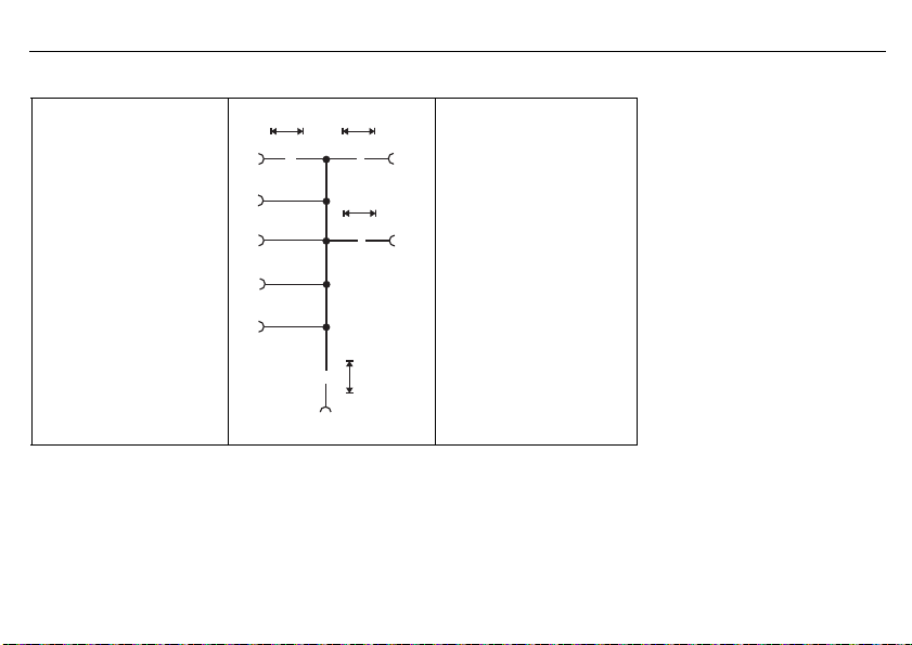
Schematic representation of a combination of safety-related parts of controls for processing a typical safety function
1 2
SRP/CS
a
SRP/CS
b
SRP/CS
c
ILO
i
ab
i
bc
I Input
L Logic
OOutput
1 Start event, e.g. manual actuation of a button, opening of a protective guard,
interruption of the beam of an AOPD
2 Drive unit of the machine, e.g. motor brake
2014-05-01
6 Safety Manual
55
Page 56

2014-05-01
6 Safety Manual
56
6.12 Evaluating the achieved Performance Level PL and the relationship to the SIL
For application in this part of DIN EN ISO 13849, the capability of safety-related parts to perform a safety function is expressed
through the determination of a Performance Level.
The PL must be assessed for each selected SRP/CS and/or SRP/CS combination that performs a safety function. The PL of
the SRP/CS must be determined by assessing the following aspects:
- The MTTF
- The DC (see Appendix E)
- The CCF (see Appendix F)
- The structure (see section 6)
- The behavior of the safety function under failure conditions (see section 6)
- Safety-related software (see 4.6 and Appendix J)
- Systematic failures (see Appendix G)
- The capability to perform a safety function under predictable ambient conditions
value of individual components (see Appendices C and D)
c
The following diagram depicts the procedure for selecting the categories in combination with MTTF
DC
to achieve the required PL for each safety function.
avg
for each channel and the
d
Page 57

Relationship between the categories DC
PL Performance Level
1MTTF
2MTTF
3MTTF
of each channel = low
d
of each channel = medium
d
of each channel = high
d
, MTTFd of each channel and PL
avg
2014-05-01
6 Safety Manual
57
Page 58

2014-05-01
The diagram above shows the different possible combinations for assessing the category with DC
of each channel (bars). The bars in the diagram show the three MTTFd areas of each channel (low, medium and high)
MTTF
d
that can be selected to achieve the required PL.
Before the simplified procedure from the diagram shown is applied (which shows the results of different Markov models on the
basis of intended architectures from section 6), the category of the SRP/CS and the DC
must have been determined (see section 6 and Appendices C to E).
For categories 2, 3, and 4, sufficient measures against failures due to combined failures must be fulfilled (see Appendix F). Taking these parameters into account, the diagram represents a graphical procedure for determining the PL achieved by the SRP/
CS. The combination of category (including failures due to combined failures) and DC
lected in image 5. In accordance with the MTTF
column must be selected.
The vertical position of these areas determines the achieved PL, which can be read off the vertical axis. If the area covers two
or three possible PLs, the achieved PL is specified in table 7. To select the exact PL on the basis of the precise value of the
of each channel, see Appendix K.
MTTF
d
of each channel, one of the three differently hatched areas of the applicable
d
6 Safety Manual
(horizontal axis) and the
avg
and the MTTFd of each channel
avg
determines which column must be se-
avg
58
Page 59

6.13 Other applicable device documentation
For temperature monitoring unit 701150 the measures, values, and requirements specified in this Operating Manual regarding
installation, electrical connection, function, and startup must be observed.
6.14 Behavior during operation and in case of malfunction
Behavior during operation and in case of a malfunction is described in the Operating Manual.
A functional test must be performed after startup, repair in the safety system, or a change in safety-related parameters.
If an error is detected during a functional test, measures must be taken to once again ensure the functional capability of the
safety system. This, for example, can be done by replacing the logic unit.
Appropriate documentation of tests that are performed is recommended.
6.15 Regular tests
No test is required for SIL2 and SIL3 certified systems since the proof check equals the lifetime. Each is ten years.
H
6.15.1 Recommended tests for temperature probes
To ensure safe and reliable operation of the thermometer, the following service and maintenance work must be performed:
The following tests are recommended at certain intervals:
Every 12 months, the leakage resistance of the measuring circuit must be measured against the protection fitting (for thermocouples: only for the insulated measuring circuit; in the case of multiple measuring circuits, the insulation test must also be performed between the individual measuring circuits). The minimal leakage resistance at room temperature should be 100 MΩ at
100 V.
- Damage and corrosion of thermometers – protection tubes
- Corrosion and correct positioning of the contacts and terminals of cable connections
After the lifetime expires, the systems no longer meet the requirements according to their SIL certification.
2014-05-01
6 Safety Manual
59
Page 60

2014-05-01
- Seals of terminal heads and cable ducts
- Interruptions due to "knocking" on the thermometer/measuring insert
Since the maximum operating temperature influences the drift behavior, the thermometer should be recalibrated or replaced at
certain intervals to ensure reliable and precise temperature measurement.
The testing intervals are listed in the table below:
Maximum operating temperature
200 °C 5 years 5 years
550 °C 2 years 5 years
700 °C 1 year 2 years
1000 °C Non-precious metal 1
1500 °C 1 year
Pt - RTD temperature probe Thermocouples
year
Precious metal 2 years
6 Safety Manual
60
H
The testing intervals specified here are recommendations that must be adapted to the special conditions at the
operating location and, if necessary, the user should perform the tests more regularly.
Page 61

6.16 Certificates
2014-05-01
6 Safety Manual
61
Page 62

2014-05-01
6 Safety Manual
62
Page 63

2014-05-01
6 Safety Manual
63
Page 64

2014-05-01
6 Safety Manual
64
Page 65

2014-05-01
6 Safety Manual
65
Page 66

2014-05-01
6 Safety Manual
66
Page 67

2014-05-01
6 Safety Manual
67
Page 68

2014-05-01
CERTIFICATE OF COMPLIANCE
Certificate Number
20120613-E325456
Report Reference
E325456-20120611
Issue Date
2012-JUNE-13
UL LLC
Any information and documentation involving UL Mark services are p rovided on behalf of UL LLC (UL) or any authorized licensee of UL. For questions, please
contact a local UL Customer Service Representative at www.ul.com/contact us
Page 1 of 1
Issued to:
O
MORITZ-JUCHHEIM-STRASSE 1
36039 FULDA, GERMANY
This is to certify that
f
Self-resetting Temperature Limiters, Series STW 701150
N
-self-resetting Temperature Limiters, Series STB 701150
this Certificate.
Standard(s) for Safety:
UL 60730-1, Standard for Automatic Electrical Controls for Household and Similar Use, Part
1: General Requirements
UL 60730-2-
2: Particular Requirements For Temperature Sensing Controls
CAN/CSA-E60730-1:02, Canadian Standard for Automatic Electrical Controls for Household
and Similar Use, Part 1: General Requirements
CAN/CSA-E60730-2-9:01, Canadian Standard for Automatic Electrical Controls for
Household and Similar Use, Part 2: Particular Requirements For Temperature Sensing Controls
UL 1998, Standard for Software in Programmable Components
Additional Information:
See the UL Online Certifications Directory at www.ul.com/database for
additional information
Only those products bearing the UL Recognized Component Marks for the U.S. and Canada should be considered as being
covered by UL's Recognition and Follow-Up Service and meeting the appropriate U.S. and Canadian requirements.
The UL Recognized Component Mark for the U.S. generally consists of the manufacturer’s identification and catalog
number, model number or other product designation as specified under “Marking” for the particular Recognition as
published in the appropriate UL Directory. As a supplementary means of identifying products that have been produced
under UL’s Component Recognition Program, UL’s Recognized Component Mark:
, may be used in conjunction with the
required Recognized Marks. The Recognized Component M ark is required when specified in the UL Directory preceding
the recognitions or under “Markings” for the individual recognitions. The UL Recognized Component Mark for Canada
consists of the UL Recognized Mark for Canada:
and the manufacturer’s identification and catalog number, model
number or other product designation as specified under “Marking” for the particular Recognition as published in the
appropriate UL Directory.
The final acceptance of the component is dependent upon its installation and use in complete equipment submitted to UL
LLC.
Look for the UL Recognized Component Mark on the product.
6 Safety Manual
representative samples o
William R. Carney, Director, North American Certification Programs
9, Standard for Automatic Electrical Controls for Household and Similar Use, Part
Have been investigated by UL in accordance with the Standard(s) indicated on
on
Component - Temperature-Sensing Controls
JUM
GMBH & CO KG
68
Page 69

2014-05-01
6 Safety Manual
69
Page 70

2014-05-01
7 Configuration level
7 Configuration level
7.1 Navigation principle
All the parameters are freely accessible at the factory, but they can be disabled via the setup program.
v Chapter 9.3 “Forgotten the code?”
Parameters of the configuration level which are not required are automatically hidden depending on the setting.
70
Page 71

7.2 Analog inputs
V
V
7.2.1 Connection
Two sensors This setting is provided for dual probes or for two different probes.
Single Pt100 in 2-wire circuit
Single4to20mA
k Factory setting
2014-05-01
Comment
Each of the two analog inputs is monitored separately for probe break, probe
short-circuit.
Caution:
When only one probe (SIL2) is connected, the temperature limiter device is
reduced from SIL3 to SIL2!
However, the internal 2-channel structure (1oo2D) in the device still remains.
Both channels measure the same sensor due to the simplified external wiring.
Caution:
When only one probe (SIL2) is connected, the temperature limiter device is
reduced from SIL3 to SIL2!
However, the internal 2-channel structure (1oo2D) in the device still remains.
Both channels measure the same current signal due to the simplified external
wiring.
7 Configuration level
71
Page 72

2014-05-01
7 Configuration level
72
7.2.2 Sensor type 1
For analog input 1
Pt100 DIN EN 60751 In 3-wire circuit -1999 to +9999 °C -205 °C/ +855 °C
Pt1000 DIN EN 60751 In 3-wire circuit -1999 to +9999 °C
Pt100 DIN EN 60751 in 2-wire circuit -1999 to +9999 °C
Pt1000 DIN EN 60751 in 2-wire circuit -1999 to +9999 °C
W3Re-W25Re “D” Thermocouple -1999 to +9999 °C -5 to +2500 °C
Cu-CuNi “T” Thermocouple DIN EN 60584 -1999 to +9999 °C -205 to +405 °C
Fe-CuNi “J” Thermocouple DIN EN 60584 -1999 to +9999 °C -205 to +1205 °C
Cu-CuNi “U” Thermocouple DIN 43710 -1999 to +9999 °C -205 to +605 °C
Fe-CuNi “L” Thermocouple DIN 43710 -1999 to +9999 °C -205 to +905 °C
NiCr-Ni “K” Thermocouple DIN EN 60584 -1999 to +9999 °C -205 to +1377 °C
Pt10Rh-Pt “S” Thermocouple DIN EN 60584 -1999 to +9999 °C -5 to +1773 °C
Pt13Rh-Pt "R" Thermocouple DIN EN 60584 -1999 to +9999 °C -5 to +1773 °C
Pt30Rh-Pt6Rh “B” Thermocouple DIN EN 60584 -1999 to +9999 °C 295 to 1825 °C
NiCrSi-NiSi "N" Thermocouple DIN EN 60584 -1999 to +9999 °C -105 to +1305 °C
4to20mA
Comment
Standard signal
Setting range for limit
value:
(can be restricted via
the setup)
-1999 to +9999 °C 3.6 to 21 mA
Limits for
Underrange /
overrange
-205 °C/ +855 °C
-205 °C/ +855 °C
-205 °C/ +855 °C
k Factory setting
Page 73

Parameter Comment
7.2.3 Offset 1
7.2.4 Lead wire resistance 1
7.2.5 Filter time 1
7.2.6 Scaling start 1
7.2.7 Scaling end 1
Using Offset1, a measured value at the analog input
can be corrected by the value entered above the total
measuring range.
Analog-input1 lead wire resistance
in 2-wire circuit
This value is used to compensate the resistance of the
probe line and depends on the line length.
Enter the ohmic resistance of the probe line here to
achieve the best possible temperature measurement.
Time constant of the digital input filter
2nd order for analog input 1
If the input signal changes suddenly, approx. 26 % of
the change is recorded following a period that corresponds to the filter time constant dF (2 x dF: approx.
59 %; 5 x dF: approx. 96 %).
Value 0 means: filter switched off
If the filter time is long:
- Interfering signals are better absorbed
- Measured value display responds more slowly to
changes
Important information: This setting only occurs if the
sensor type 1 was set to 4 to 20mA!
Here, the user selects which value (i.e. pressure)
should be displayed at 4 mA.
Here, the user selects which value (i.e. pressure)
should be displayed at 20 mA.
Value range
(factory-setting in bold)
-999.9 to 0.0 to 999.9
0.0 to 30.0 ohm
0.0 to 0.6 to 100 sec.
-9999 to 0 to 9999
-9999 to 100 to 9999
2014-05-01
7 Configuration level
73
Page 74

2014-05-01
7 Configuration level
74
7.2.8 Sensor type 2
For analog input2
Pt100 DIN EN 60751 In 3-wire circuit -1999 to +9999 °C -205 °C/ +855 °C
Pt1000 DIN EN 60751 In 3-wire circuit -1999 to +9999 °C
Pt100 DIN EN 60751 in 2-wire circuit -1999 to +9999 °C
Pt1000 DIN EN 60751 in 2-wire circuit -1999 to +9999 °C
W3Re-W25Re “D” Thermocouple -1999 to +9999 °C -5 to +2500 °C
Cu-CuNi “T” Thermocouple DIN EN 60584 -1999 to +9999 °C -205 to +405 °C
Fe-CuNi “J” Thermocouple DIN EN 60584 -1999 to +9999 °C -205 to +1205 °C
Cu-CuNi “U” Thermocouple DIN 43710 -1999 to +9999 °C -205 to +605 °C
Fe-CuNi “L” Thermocouple DIN 43710 -1999 to +9999 °C -205 to +905 °C
NiCr-Ni “K” Thermocouple DIN EN 60584 -1999 to +9999 °C -205 to +1377 °C
Pt10Rh-Pt “S” Thermocouple DIN EN 60584 -1999 to +9999 °C -5 to +1773 °C
Pt13Rh-Pt "R" Thermocouple DIN EN 60584 -1999 to +9999 °C -5 to +1773 °C
Pt30Rh-Pt6Rh “B” Thermocouple DIN EN 60584 -1999 to +9999 °C 295 to 1825 °C
NiCrSi-NiSi "N" Thermocouple DIN EN 60584 -1999 to +9999 °C -105 to +1305 °C
4to20mA
Comment
Standard signal
Setting range for limit
value:
(can be restricted via
the setup)
-1999 to +9999 °C 3.6 to 21 mA
Limits for
Underrange /
overrange
-205 °C/ +855 °C
-205 °C/ +855 °C
-205 °C/ +855 °C
k Factory setting
Page 75

Parameter Comment
7.2.9 Offset 2
7.2.10 Lead wire resistance 2
7.2.11 Filter time 2
7.2.12 Scaling start 2
7.2.13 Scaling end 2
Using Offset2, a measured value at the analog input
can be corrected by the value entered over the total
measuring range.
Lead wire resistance analog input 2
in 2-wire circuit
This value is used to compensate the resistance of the
probe line and depends on the line length.
Enter the ohmic resistance of the probe line here to
achieve the best possible temperature measurement.
Time constant of the digital input filter
2nd order for analog input 2
If the input signal changes suddenly, approx. 26 % of
the change is recorded following a period that corresponds to the filter time constant dF (2 x dF: approx.
59 %; 5 x dF: approx. 96 %).
Value 0 means: filter switched off
If the filter time is long:
- Interfering signals are better absorbed
- Measured value display responds more slowly to
changes
Important information: This setting only occurs if the
sensor type 2 was set to 4 to 20mA!
Here, the user selects which value (i.e. pressure)
should be displayed at 4 mA.
Here, the user selects which value (i.e. pressure)
should be displayed at 20 mA.
Value range
(factory-setting in bold)
-999.9 to 0.0 to 999.9
0.0 to 30.0 ohm
0.0 to 0.6 to 100 sec.
-9999 to 0 to 9999
-9999 to 100 to 9999
2014-05-01
7 Configuration level
75
Page 76

2014-05-01
7.3 Limiter/monitor
Parameter Comment
7.3.1 Device function
Safety temperature limiter (STB) initial startup:
Regardless of the switching status of the alarm relay
output prior to power failure, the STB remains locked
when power returns.
The purpose of this factory setting is to ensure that the
device will be in a safe switched-off state when the
voltage supply is switched on for the first time.
After this initial startup, the device function can be set
to STB or STW.
Safety temperature limiter STB:
The device must be manually reset using the keypad or
the binary input as soon as the main measured value is
back within the valid range.
Safety temperature monitor STW
The device is automatically reset as soon as the main
measured value is back within the valid range.
7 Configuration level
Value range
(factory-setting in bold)
STB initial startup, STB,
STW
76
Page 77

Parameter Comment
S
P
14
1615
Ö
3,15A
S
P
14
1615
Ö
3,15A
Hysteresis
Hysteresis
S
P
11
12 13
Ö
Min. alarm
( direct or S-Function)older devices:
Relay output pre-alarm
active(KV)
Relay output pre-alarm
(KV) inaktive
Relay output alarm active
Relay output alarm inactive
Pre-alarm range
Alarm range Valid range
Limit Value
Min. set.range Max. set.range
Measured value
Measured value
Distance from limit value
Pre-alarm (absolute value)
LED KV lights up yellow
LED K1, K2 light up red
LED OK lights up green
7.3.2 Switching behavior
Min. alarm:
If the measured value falls below the limit value, the
alarm relay output switches to OFF. The LEDs K1 and
K2 light up red and the measured values flash in the
display.
Value range
(factory-setting in bold)
Max. alarm, min. alarm
If set to the safety temperature limiter (STB) setting, this condition remains even when the main
measured value is back in the valid range. Only when the "Reset" key is pressed or a switch is
activated when the binary input is respectively configured will the alarm relay output switch on
again and the OK LED light up green.
When setting the safety temperature monitor (STW), the alarm relay output automatically
switches back to ON as soon as the main measured value is back within the valid range.
2014-05-01
7 Configuration level
77
Page 78

2014-05-01
Limit value
S
P
14
1615
Ö
3,15A
S
P
14
1615
Ö
3,15A
Min. set.range Max. set.range
Hysteresis
Relay output Alarm aktive
Relay output Alarm inactive
S
P
11
12 13
Ö
Max. alarm (older devices: inverse or O-Function)
Distance from limit value
Pre-alarm range
Measured value
Measured value
Alarm rangeValid range
Pre-alarm (absolute value)
Hysteresis
Relay output pre-alarm
activeKV
Relay output pre-alarm
KV inactive
LED KV lights up yellow
LED OK lights up green
LED K1, K2 lights up red
7 Configuration level
Parameter Comment
Max. alarm:
If the measured value exceeds the limit value, the alarm
relay output switches OFF. The LEDs K1 and K2 light
up red and the measured values flash in the display.
If set to the safety temperature limiter (STB) setting, this condition remains even when the main
measured value is back in the valid range. Only when the "Reset" key is pressed or a switch is
activated when the binary input is respectively configured will the alarm relay output switch on
again and the OK LED light up green.
When setting the safety temperature monitor (STW), the alarm relay output automatically
switches back to ON as soon as the main measured value is back within the valid range.
78
Value range
(factory-setting in bold)
Page 79

V
Parameter Comment
H
The pre-alarm responds according to
its setting to the main measured value and also to the diagnostic functions registered via the LED KD.
Depending on which measured value
initially exceeds or falls short of the
pre-alarm, a pre-alarm is triggered.
7.3.3 Limit value, hysteresis
7.3.4 Pre-alarm function
Limit value alarm:
If this value is exceeded or not reached, this affects the
alarm relay output depending on the switching behavior.
Hysteresis limit value:
Difference between the switch-off and switch-on
threshold, e.g. for rising and falling temperatures.
No function
Pre-alarm relay output is inactive
Absolute value:
Pre-alarm relay output is triggered if the value for the
pre-alarm is exceeded.
Limit val. dist.
Here, the set value for the pre-alarm is used on a basis
that is relative to the limit value. If, for example, a prealarm of 10 K is entered, the pre-alarm relay output
always switches at 10 K before the limit value, regardless of how the limit value is set.
Caution
The pre-alarm function is not part of the safety function!
Value range
(factory-setting in bold)
-200 to 0 to 850
Depends on setting range
min. and max.
0to2 to 100
No function,
Absolute value,
Limit val. dist.
7.3.5 Pre-alarm, hysteresis
2014-05-01
Pre-alarm
The value that triggers the pre-alarm relay output as an
absolute value or relative to the limit value.
Pre-alarm hysteresis:
Difference between the switch-off and switch-on
threshold, e.g. for rising and falling temperatures.
7 Configuration level
-9999 to 0 to 9999
0to2 to 100
79
Page 80

2014-05-01
Parameter Comment
7.3.6 Limit value difference,
hysteresis
Important information:
If, for example, temperature differences arise as a result of the spatial arrangement of a dual probe, an alarm may be triggered
by the concurrency monitoring even though the temperature being monitored has not yet been exceeded.
In this case, the difference monitoring limit value can be adjusted accordingly.
7.3.7 Setting range min. (formerly ALHI)
This is the lower limit of the setting
range for the limit value.
7.3.8 Setting range max. (formerly ALLO)
This is the upper limit of the setting
range for the limit value.
The admissible limits for DIN authorized probes:
Limit value difference monitoring:
If the value of the temperature difference of the analog
input 1-2 is exceeded, the alarm relay output is
switched.
Hysteresis difference monitoring:
Difference between the switch-off and switch-on
threshold, e.g. for rising and falling differential values.
This value may not be lower than the lower end of the
connected probe or unit signal measuring range. It may
also not be set higher than the setting for the alarm
limit value.
This value may not be greater than the higher end of
the connected probe or unit signal measuring range. It
may also not be set lower than the setting for the alarm
limit value.
7 Configuration level
Value range
(factory-setting in bold)
0to50 to 100
0to2 to 100
-9999 to -200 to limit value
°C
Limit
value to 850 to 9999 °C
80
v Chapter 8.12 “Probes for the operating medium air” and
v Chapter 8.13 “Probes for the operating medium water and oil”
Page 81

7.4 Binary input
Parameter Comment
7.4.1 Function
This sets the function that should be controlled by the binary
input.
The binary input does not have a function
The binary input performs a reset as described in Chapter 7.3.1
“Device function”.
The function only responds to the switching edge from "open" to
"closed" state.
Protection against unauthorized key operation Key lock
Configuration level is locked. Level lock
k Factory setting
2014-05-01
Value range
(factory-setting in bold)
No function
Unlocking
7 Configuration level
81
Page 82

2014-05-01
7.5 Analog output
Parameter Comment
7.5.1 Function
7.5.2 Signal type
7.5.3 Scaling start
7.5.4 Scaling end
Here, the measured value that is to be shown at the
analog output is set.
Main measured value:
With the max-alarm switching behavior, the greater of
the two measured values is shown; with the min-alarm,
the lower of the two measured values is shown.
Measured value1:
Measured value of analog input 1 (E1) is shown
Measured value2:
Measured value of analog input 2 (E2) is shown
Difference:
E1-E2 is shown
The signal that should be output by the analog output
can be set with scaling start and end.
4to20mA 4to20mA,
0to20mA
2to10V
0to10V
v
v
7 Configuration level
Value range
(factory-setting in bold)
Main measured value
Measured value1
Measured value2
Difference
0to20mA
2to10V
0to10V
Picture in Chapter 7.5.6 -9999 to -200 to 9999
Picture in Chapter 7.5.6 -9999 to 800 to 9999
82
Page 83

Parameter Comment
7.5.5 Error signal
If, for the measured value 1 or 2, the value is exceeded,
not reached, or a diagnostic error occurs, the current or
voltage value set on the analog output is output as a
so-called error signal.
For signal type 4 to 20 mA 3.4 or 21.2 mA
For signal type 0 to 20 mA 0 or 21.2 mA
For signal type 2 to 10 V 1.7 or 10.4 V
For signal type 0 to 10 V 0 or 10.4 V
Value range
(factory-setting in bold)
2014-05-01
7 Configuration level
83
Page 84

2014-05-01
V
Measured value
Standard signal
for analog output
4 mA
20 mA
3.8 mA
20.5 mA
7 Configuration level
7.5.6 Behavior when leaving the scaling range
The standard signal range of the analog output is limited as follows according to recommendation of Namur NE 43:
Signal type
0: 4to20mA 3.8 mA 20.5 mA
1: 0 to 20 mA 0mA 20.5 mA
2: 2to10V 1.8 V 10.2 V
3: 0to10V 0V 10.2 V
Lower
limit
Upper
limit
k Factory setting
Caution The analog output is not part of the safety function!
84
Page 85

7.6 Display/operation
A
When the measurement unit changes
to °F, the measured value is converted.
All other values referring to the measured value (e.g. limit value) remain in
their value!
Parameter Comment
7.6.1 Language
7.6.2 Unit
7.6.3 Decimal place
7.6.4 Normal display
2014-05-01
Value range
(factory-setting in bold)
German German, English, French
English
French
Here a unit for the measured value can be assigned. °C, °F, %, te xt
°C
°F
%
Te xt :
Via the setup program, 2 characters can be entered
here for another unit, e.g. Pa (Pascal).
No decimal place No decimal place,
One decimal place
This sets the view that appears after the voltage supply
is switched on.
v Chapter “Operating overview”
Main measured value
Measured values
Limit value
Pre-alarm
Difference
7 Configuration level
One decimal place
Main measured value,
measured values, limit
value, pre-alarm, difference
85
Page 86

2014-05-01
H
If the code is forgotten, a new code can be
transferred to the device via the setup program
.
Parameter Comment
7.6.5 Contrast
7.6.6 Lighting
7.6.7 Time-out light
7.6.8 Time-out operation
7.6.9 Code
7 Configuration level
Value range
(factory-setting in bold)
Screen contrast
Difference in brightness between black and
white pixels
Here the background lighting of the display is set. Off, On, During operation
Off:
Always switched off
On:
Always switched on
During operation:
The background illumination is only switched on when
the keys are operated and it lights up until the time for
the time-out light has expired.
Here a waiting period for the switch-off of the background lighting is set.
Here, the waiting period is set for the return from the
configuration to normal display.
To protect against unauthorized manipulations, a code
can be set here for locking the configuration level.
0 means: code request switched off
0to5 to 10
0 to 100 sec.
0 to 100 sec.
0 to 9999
86
v Chapter 9.3 “Forgotten the code?”
Page 87

7.7 Service
Parameter Comment
7.7.1 Limit switching cycle
Limit value for relay switching cycles
Here, the limit value for the admissible relay switching
cycles is set.
If the counter value for Current switching cycles is
greater than this value, the display values flash and the
alarm relay output secedes.
If "0" is set the function is inactive.
Value range
(factory-setting in bold)
0 to 99999
7.7.2 Current switching cycles
7.7.3 Operating hours
2014-05-01
Relay switching cycle counter
Here, the switching cycles for the relay are only counted if the top limit value for relay switching cycles is
not set to "0" and is thus inactive.
The value can then be adjusted as required and therefore adapted accordingly to the plant.
The switching cycle counter remains at 99999.
Operating hour counter
The counter adds up the operating hours during which
the device was connected to the voltage supply.
The value cannot be changed and can be used as a
measure of how long the device was actually in operation after leaving the plant.
7 Configuration level
0 to 99999
0 to 99999
87
Page 88

2014-05-01
8 Technical data
8.1 Analog inputs
RTD temperature probe
8 Technical data
88
Designation Measuring range Accuracy
Pt100 DIN EN 60751 -200 to +850 °C 0.5% / 0.1% 50 ppm/K
Pt1000 DIN EN 60751 -200 to +850 °C 0.5% / 0.1% 50 ppm/K
Connection type 2-wire, 3-wire circuit Maximum output resistance 30 Ω
Measuring rate 210 ms
Error tolerance time ≤ 5s time taken into account for all diagnosis tests
Input filter Digital filter, 2nd priority; filter constant can be set from 0 to 100 s
Special features Individual probe Pt100 2-wire,
display can also be programmed in °F
2/3-wire circuit
1
Ambient temperature
influence
Thermocouples
Designation Measuring range Accuracy
Fe-CuNi "L" DIN 43710 -200 to +900 °C 0.4% 100 ppm/K
Fe-CuNi "J" DIN EN 60584 -200 to +1200 °C 0.4% 100 ppm/K
Cu-CuNi "U" DIN 43710 -200 to +600 °C 0.4% 100 ppm/K
Cu-CuNi "T" DIN EN 60584 -200 to +400 °C 0.4% 100 ppm/K
1
Ambient temperature
influence
Page 89

NiCr-Ni "K" DIN EN 60584 -200 to +1372 °C 0.4% 100 ppm/K
NiCrSi-NiSi "N" DIN EN 60584 -100 to +1300 °C 0.4% 100 ppm/K
Pt10Rh-Pt "S" DIN EN 60584 0 to +1768 °C 0.4% 100 ppm/K
Pt13Rh-Pt "R" DIN EN 60584 0 to +1768 °C 0.4% 100 ppm/K
Pt30Rh-Pt6Rh "B" DIN EN 60584 300 to 1820 °C 0.4% 100 ppm/K
W3Re-W25Re "D" 0 to 2495 °C 0.4 % 100 ppm/K
Cold junction Pt100 internal
Cold junction accuracy ± 1 K
Measuring rate 210 ms
Error tolerance time ≤ 5 s time taken into account for all diagnosis tests
Input filter Digital filter, 2nd priority; filter constant can be set from 0 to 100 s
1.The accuracy values refer to the maximum measuring range.
Direct current
Measuring range Accuracy Ambient temperature
4 to 20 mA, voltage drop < 2 V 0.2 % 150 ppm/K
Scaling Can be freely programmed within the limits
Measuring rate 210 ms
Error tolerance time ≤ 5 s time taken into account for all diagnosis tests
Input filter Digital filter, 2nd priority; filter constant can be set from 0 to 100 s
Special features Individual probe 4 to 20 mA
influence
2014-05-01
8 Technical data
89
Page 90

2014-05-01
8.2 Analog output
8 Technical data
90
Type of signal
Current 4 to 20 mA
0 to 20 mA
Voltage 2 to 10 V
0 to 10 V
Accuracy Residual ripple Load influence Temperature influ-
≤ 0.5 % ± 0.5 % at 300 Ω ± 0.05 mA/ 100 Ω 150 ppm / K ≤ 500 Ω
≤ 0.5 % ± 0.5 % ± 15 mV 150 ppm / K ≥ 500 Ω
8.3 Binary input
Connection Function
1 potential-free contact Unlocking, keyboard locking, level locking can be configured
8.4 Relay outputs
Relay output KV Relay (changeover contact) without shroud
Relay output alarm Changeover contact
30000 operations at a performance of 3 A /250 V, 50 Hz resistive load
or maximum DC 30 V / 3 A. Minimal current: DC 12 V / 100 mA.
Contact protection switching: safety fuse 3.15 AT, installed in the N/O contact arm
30000 operations at a performance of 3 A /230 V, 50 Hz resistive load
or maximum DC 30 V / 3 A. Minimal current: DC 12 V / 100 mA.
ence
Load
resistance
Page 91

8.5 Measuring circuit monitoring
RTD temperature probe in
three-wire circuit and
double thermocouples
Overrange
and underrange
Probe and wire break Is detected
Probe short-circuit Is detected
Is detected
LED K1, K2, KD and KV are lit;
">>>>" flashes in the display for overrange, "<<<<" for underrange.
LED K1, K2, KD and KV are lit;
">>>>" flashes in the display; relay output "Alarm" is inactive
LED K1, K2, KD and KV are lit;
"<<<<" flashes in the display;
relay output "Alarm" is inactive
8.6 Voltage supply
Voltage supply AC/DC 20 to 30 V, 48 to 63 Hz
AC 110 to 240 V, +10/-15 %, 48 to 63 Hz
Power consumption 12 VA
Power loss 12 W
2014-05-01
Thermocouples Current 4 to 20mA
LED K1, K2, KD and KV are lit;
">>>>" flashes in the display;
relay output "Alarm" is inactive
Is detected by difference
monitoring of the analog inputs
LED K1, K2, KD and KV are lit;
"<<<<" flashes in the display;
relay output "Alarm" is inactive
v Chapter 7.3.6 "Limit
value difference, hysteresis"
8 Technical data
91
Page 92

2014-05-01
8 Technical data
8.7 Test voltages according to EN 60730, part 1
Input and output against voltage supply
- At a voltage supply AC 110 to 240 V +10 % /-15 % 3.7 kV/50 Hz
- At a voltage supply AC/DC 20 to 30 V, 48 to 63 Hz 3.7kV/50 Hz
8.8 Electrical safety
Clearances / creep paths
Mains to electronic components
and probes
Mains to relays
Relays to electronic components
and probes
Electrical safety According to DIN EN 14597 (DIN EN 60730-2-9)
Protection rating I With internal separation from SELV current circuits
≥ 6 mm / ≥ 8 mm
≥ 6 mm / ≥ 8 mm
≥ 6 mm / ≥ 8 mm
Overvoltage category III, pollution degree 2
8.9 Environmental influences
Ambient temperature range 0 to. +55 °C
Storage temperature range -30 to +70 °C
Temperature influence ≤ ± 0.005 % / K dev. from 23 °C 1 for RTD temperature probes
≤ ± 0.01% / K dev. from 23°C
Environmental performance 85 % rel. humidity without condensation
(3K3 with extended temperature range according to DIN EN 60721-3-3)
1
for thermocouples and current
92
Page 93

EMC According to DIN EN 14597 and standards from the standard series DIN EN 61326
Emitted interference Class B
Interference resistance Evaluation criteria FS according to DIN EN 14597, regulation and control devices (RS)
1. All specifications refer to the measuring range limit value
8.10 Case
Material Polycarbonate
Flammability class UL 94 V0
Electrical connection On the front via screw terminals up to max. 2.5 mm
Installation On 35 mm DIN rail according to EN 60715
Installation position Any
Weight Approx. 230 g
Protection class IP 20 according to DIN EN 60529
2
2014-05-01
8 Technical data
93
Page 94

2014-05-01
8 Technical data
94
8.11 Approvals/approval marks
Approval marks Inspection author-
DIN DIN CERTCO STB/STW1223 DIN EN 14597 All device versions:
SIL2, SIL3 TÜV Nord (German
PL e DIN EN ISO 13849 All device versions:
c UL us Underwriters Labo-
GL Germanischer Lloyd 36 790-11HH All device versions:
Pressure equipment
directive
ity
Technical Inspection Agency)
ratories
TÜV Süd (German
Technical Inspec- D0046
tion Agency)
Certificates/certification
numbers
SAS-0190/2006 TB2_V 3.0 DIN EN 61508 All device versions:
20120613-E325456 Applied for UL 60730-2-9 All device versions:
D07 202 1045 Z 0031/14/ DGRL 97/23/EG All
Inspection basics Valid for
device versions:
Page 95

8.12 Probes for the operating medium air
Note: Because of the high response accuracy, the use of thermowells (pockets) is not admissible.
Actual type designation Old type
designation
Probe type Temperature range Nom. length mm Process connection
RTD temperature probe Data Sheet 90.2006
902006/65-228-1003-1-15-500-668/000 - 1 x Pt100 -170 ... +700°C 500
902006/65-228-1003-1-15-710-668/000 - 710
902006/65-228-1003-1-15-1000-668/000 - 1000
902006/55-228-1003-1-15-500-254/000 - 1 x Pt100 -170 ... +700°C 500
902006/55-228-1003-1-15-710-254/000 - 710
902006/55-228-1003-1-15-1000-254/000 - 1000
902006/65-228-2003-1-15-500-668/000 90.271-F01 2 x Pt100 -170 ... +700°C 500 Stop flange,
movable
902006/65-228-2003-1-15-710-668/000 90.272-F01 710
902006/65-228-2003-1-15-1000-668/000 90.273-F01 1000
902006/55-228-2003-1-15-500-254/000 - 2 x Pt100 -170 ... +700°C 500 movable
G1/2 compression
clamp
902006/55-228-2003-1-15-710-254/000 - 710
902006/55-228-2003-1-15-1000-254/000 - 1000
Thermocouples Data Sheet 90.1006
901006/65-547-2043-15-500-668/000 90.019-F01 2 x NiCr-Ni, TypE „K“ -35 ... +800°C 500 Stop flange,
movable
901006/65-547-2043-15-710-668/000 90.020-F01 710
901006/65-547-2043-15-1000-668/000 90.021-F01 1000
901006/65-546-2042-15-500-668/000 90.019-F11 2 x Fe-CuNi, TypE „L“ -35 ... +700°C 500
901006/65-546-2042-15-710-668/000 90.020-F11 710
901006/65-546-2042-15-1000-668/000 90.021-F11 1000
901006/66-550-2043-6-500-668/000 90.023-F01 2 x NiCr-Ni, TypE „K“ -35 ... +1000°C 500
901006/66-550-2043-6-355-668/000 90.023-F02 355
901006/66-550-2043-6-250-668/000 90.023-F03 250
901006/66-880-1044-6-250-668/000 90.021 1 x PT10Rh-PT, TypE „S“ 0 ... 1300°C 250
901006/66-880-1044-6-355-668/000 90.022 355
901006/66-880-1044-6-500-668/000 90.023 500
901006/66-880-2044-6-250-668/000 90-D-021 2 x PT10Rh-PT, TypE „S“ 0 ... 1300°C 250 Stop flange,
movable
901006/66-880-2044-6-355-668/000 90-D-022 355
901006/66-880-2044-6-500-668/000 90-D-023 500
2014-05-01
8 Technical data
95
Page 96

2014-05-01
901006/66-953-1046-6-250-668/000 90.027 1 x PT30Rh-PT6Rh, TypE „B“ 600 ... 1500°C 250
901006/66-953-1046-6-355-668/000 90.028 355
901006/66-953-1046-6-500-668/000 90.029 500
901006/66-953-2046-6-250-668/000 90-D-027 2 x PT30Rh-PT6Rh, TypE „B“ 600 ... 1500°C 250
901006/66-953-2046-6-355-668/000 90-D-028 355
901006/66-953-2046-6-500-668/000 90-D-029 500
Note: Because of the high response accuracy, the use of thermowells (pockets) is not admissible.
Actual type designation Old type
designation
Probe type Temperature range Nom. length mm Process connection
RTD temperature probe Data Sheet 90.2006
90.2006/10-402-1003-1-9-100-104/000 1 x Pt100 -40 ... +400°C 100 G1/2 screw connection
90.2006/10-402-2003-1-9-100-104/000 2 x Pt100 100
902006/54-227-2003-1-15-710-254/000 90.272-F02 2 x Pt100 -170 ... 550°C 65...670 movable
G1/2 compression clamp
902006/54-227-1003-1-15-710-254/000 90.272-F03 1 x Pt100 65...670
902006/10-226-1003-1-9-250-104/000 90.239 1 x Pt100 -170 ... 480°C 250 G1/2 screw connection
902006/10-226-2003-1-9-250-104/000 90-D-239 2 x Pt100 250
Thermocouples Data Sheet 90.1006
901006/54-544-2043-15-710-254/000 90.020-F02 2 x NiCr-Ni, Type „K“ -35 ... 550°C 65...670 movable
G1/2 compression clamp
901006/54-544-1043-15-710-254/000 90.020-F03 1 x NiCr-Ni, Type „K“ 65...670
901006/54-544-2042-15-710-254/000 90.020-F12 2 x FeCuNi, Type „L“ 65...670
901006/54-544-1042-15-710-254/000 90.020-F13 1 x FeCuNi, Type „L“ 65...670
8 Technical data
8.13 Probes for the operating medium water and oil
96
Page 97

Note: Because of the high response accuracy, only use thermowells (pockets) that are included in the scope of delivery.
Actual type designation Old type
designation
Probe type Temperature range Nom. length mm Process connection
RTD temperature probe Data Sheet 90.2006
902006/53-505-2003-1-12-190-815/000 90D239-F03 2 x Pt100 -40 ... +400 °C 190
902006/53-507-2003-1-12-100-815/000 90.239-F02 2 x Pt100
(arranged one
below the other
in protection tube)
-40 ... +480 °C 100
902006/53-507-2003-1-12-160-815/000 90.239-F12 160
902006/53-507-2003-1-12-190-815/000 190
902006/53-507-2003-1-12-220-815/000 90.239-F22 220
902006/53-507-1003-1-12-100-815/000 90.239-F01 1 x Pt100 -40 ... +480 °C 100 weld-in sleeve
902006/53-507-1003-1-12-160-815/000 90.239-F11 160
902006/53-507-1003-1-12-220-815/000 90.239-F21 220
902006/53-505-1003-1-12-190-815/000 90.239-F03 1 x Pt100 -40 ... +400 °C 190
902006/53-505-3003-1-12-100-815/000 90.239-F07 3 x Pt100 -40 ... +400 °C 100
902006/53-505-3003-1-12-160-815/000 90.239-F17 160
902006/53-505-3003-1-12-220-815/000 90.239-F27 220
902006/40-226-1003-1-12-220-815/000 90.280-F30 1 x Pt100 -170 ... +480°C 220 weld-in sleeve
902006/40-226-1003-1-12-160-815/000 90.280-F31 160
902006/40-226-1003-1-12-100-815/000 90.280-F32 100
Thermocouples Data Sheet 90.1006
901006/53-543-1042-12-220-815/000 90.111-F01 1 x Fe-CuNi Type „L“ -35 ... 480°C 220 weld-in sleeve
901006/53-543-2042-12-220-815/000 90.111-F02 2 x Fe-CuNi Type „L“ 220
2014-05-01
8 Technical data
97
Page 98

2014-05-01
A
H
Note: Because of the high response accuracy, the use of thermowells (pockets) is not admissible.
Actual type designation Old type
designation
Probe type Temperature range Install. length mm Process connection
RTD temperature probe Data Sheet 90.2006
90.2006/10-390-1003-1-8-250-104/000 90.210-F95 1 x Pt100 max. 300°C 250
Thermocouples Data Sheet 90.1006
901006/45-551-2043-2-xxxx-11-xxxx 2 x NiCr-Ni, Typ
E
„K“ max. 1
50°C 5
0...2000
8.14 Probes for the operating medium water, oil and air
Probe short-circuit is only detectable with a double thermocouple.
The probes described in data sheets 901006 and 902006 are also certified for the Pressure Equipment Directive.
8 Technical data
98
Page 99

9 Setup program
1. Is a registered trademark of Microsoft Corporation
The program and the connection cable are available as accessories and
offer the following possibilities:
- Easy and comfortable parameterization and archiving via PC
- Easy parameter duplication for identical types of devices
9.1 Minimum hardware and software prerequisites:
- PC Pentium III or higher
- 128 MB RAM, 16 MB free on hard disk
-CD-ROM drive
- Free USB interface, mouse connection
-Microsoft
h Connect the device to the PC using the USB cable
9.2 Displaying the device software version
h Simultaneously press the and keys and hold down
This version is also recognized by the setup program and displayed under Info
The software versions of the device and the setup program
must be compatible as otherwise an error message will appear!
1
Windows1 2000/XP
Information about setup.
2014-05-01
9 Setup program
99
Page 100

2014-05-01
9 Setup program
100
9.3 Forgotten the code?
If you forget the code, it can be read out via the USB interface and the setup program.
h Perform a data transfer read-out from device.
The read-out code now appears in the setup program.
It can be retained or changed.
If "0" is set and transferred to the device, the code interrogation is deactivated and the configuration level is freely accessible.
9.4 Special function: thermocouple reverse polarity protection
If a thermocouple is incorrectly connected (reverse polarity), incorrect measured values will be displayed, e.g. negative temperatures instead of the expected positive temperatures may
be displayed.
This may lead to the set limit value never being reached. An additional limit value will be defined that is factory set to -205 °C
and the relay alarm will be triggered if the actual value falls below this limit.
This value must be effectively selected to ensure that a possible reverse polarity is detected.
 Loading...