

Page 1
JUMO GmbH & Co. KG
Delivery address: Mackenrodtstraße 14
36039 Fulda, Germany
Postal address:
36035 Fulda, Germany
Phone: +49 661 6003-0
Fax: +49 661 6003-607
E-mail: mail@jumo.net
Internet: www.jumo.net
JUMO Instrument Co. Ltd.
JUMO House
Temple Bank, Riverway
Harlow, Essex CM20 2DY, UK
Phone: +44 1279 635533
Fax: +44 1279 635262
E-mail: sales@jumo.co.uk
Internet: www.jumo.co.uk
JUMO Process Control, Inc.
6733 Myers Road
East Syracuse, NY 13057, USA
Phone: 315-437-5866
1-800-554-5866
Fax: 315-437-5860
E-mail: info.us@jumo.net
Internet: www.jumousa.com
Type 608425/2316
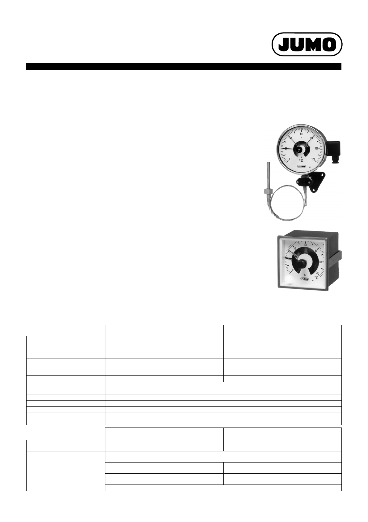
Contact Dial Thermometers
Type 608425
Particularities
• temperature controller with indication for panel or surface mounting
• Class 1
• protection up to IP65
• housing sizes: 100 mm and 160 mm diameter, bezel 96 x 96 mm
Brief description
Contact dial thermometers are universally applicable instruments with indication of the actual
value, for temperature measurement, control and monitoring.
The temperature-dependent change in volume of a liquid-filled measuring system (or the
temperature-dependent change of pressure in a gas-filled measuring system) is converted into
a rotary movement of the pointer by a Bourdon tube, without any intermediate gearing. The
rotary movement of the pointer shaft is used to operate the switched output.
The pointer is directly linked to the measuring system, which makes the overall system
extremely torsionally rigid. Vibrations are transmitted to the pointer only to a minor extent.
The switched output can be implemented as a slow-break, magnetic snap-action or inductive
contact. The slow-break or magnetic snap-action contact is an auxiliary circuit switch that,
depending on the direction of movement, opens or closes an electrical circuit at the set limits,
by means of a contact arm that is attached to the moving pointer.
The inductive contact is an electronic limit detector operated by a contactless position sensor
(proximity switch).
Data Sheet 608425
Page 1/6
Type 608425/2496
Technical data
Housing housing with bayonet lock
Enclosure protection IP65 as per EN 60 529 front: IP51 as per EN 60 529
Electrical connection terminal box: conductor cross-section up to
Glass window polycarbonate plexiglas (PMMA)
Scale white, black lettering
Accuracy class Class 1 to EN 13190
Anti-kink spring for capillary instruments, at the housing and probe
Setpoint adjustment through setpoint adjuster on the glass window
Indication correction at the back, no indication correction for styles 01 and 20 (100 mm dia.)
Temperature limits for transport and storage -20°C to +70°C (with a 0 to +60°C range: max. 65°C)
Operating position (NL) unrestricted
Measuring system range (AB) ≤ 350°C range (AB) ≤ 400°C
Time constant
t
0.632
Ambient temperature
error
at housing 0.15% of indication range
on capillary (per meter) 0.03% of indication range
2011-11-08/00402234
round panel- or surface-mounting housing
cable gland suitable for cable dia. 6.5 — 13 mm
approx. 12 sec, measured in water bath,
with a 6 mm dia. copper probe
in % of indication range (referred to the deviation from the reference value at +23°C)
per °C change of ambient temperature
per °C change of ambient temperature
At higher ambient temperatures – higher temperature indication – lower switching point
Type 608425
in stainless steel (1.4301)
2
2.5mm
Liquid filling Gas filling
square panel-mounting instrument
galvanized sheet steel housing, fixed at back by a
bracket; front bezel in stainless steel (1.4301)
back: IP00 as per EN 60 529
screw terminals: conductor cross-section up to
approx. 4 sec, measured in oil bath,
with a 10 mm dia. stainless steel probe
per °C change of ambient temperature
Typ 608425
2
2.5mm
0.05% of indication range
no effect
Page 2
JUMO GmbH & Co. KG
Delivery address: Mackenrodtstraße 14
36039 Fulda, Germany
Postal address:
36035 Fulda, Germany
Phone: +49 661 6003-0
Fax: +49 661 6003-607
E-mail: mail@jumo.net
Internet: www.jumo.net
JUMO Instrument Co. Ltd.
JUMO House
Temple Bank, Riverway
Harlow, Essex CM20 2DY, UK
Phone: +44 1279 635533
Fax: +44 1279 635262
E-mail: sales@jumo.co.uk
Internet: www.jumo.co.uk
JUMO Process Control, Inc.
6733 Myers Road
East Syracuse, NY 13057, USA
Phone: 315-437-5866
1-800-554-5866
Fax: 315-437-5860
E-mail: info.us@jumo.net
Internet: www.jumousa.com
Data Sheet 608425
Page 2/6
Standard Extra code (TZ) 442
Electrical contact
Contact type electromechanical slow-break contact
with single-pole make contacts
electromechanical magnetic snap-action contact
with single-pole make contacts
Contact rating 230 V AC/DC, +10/-15%, 48 — 63Hz, p.f = 1 (0.6)
max. 18 VA / 10 W max. 50 VA / 30 W
Switching differential ≤ 0.5% of indication range approx.2% of indication range
Switching point accuracy ±0.5% of indication range (referred to the switching point for rising temperature)
Switching reliability To ensure maximum switching reliability, we recommend a minimum voltage of 24 V and a minimum current
of 20 mA
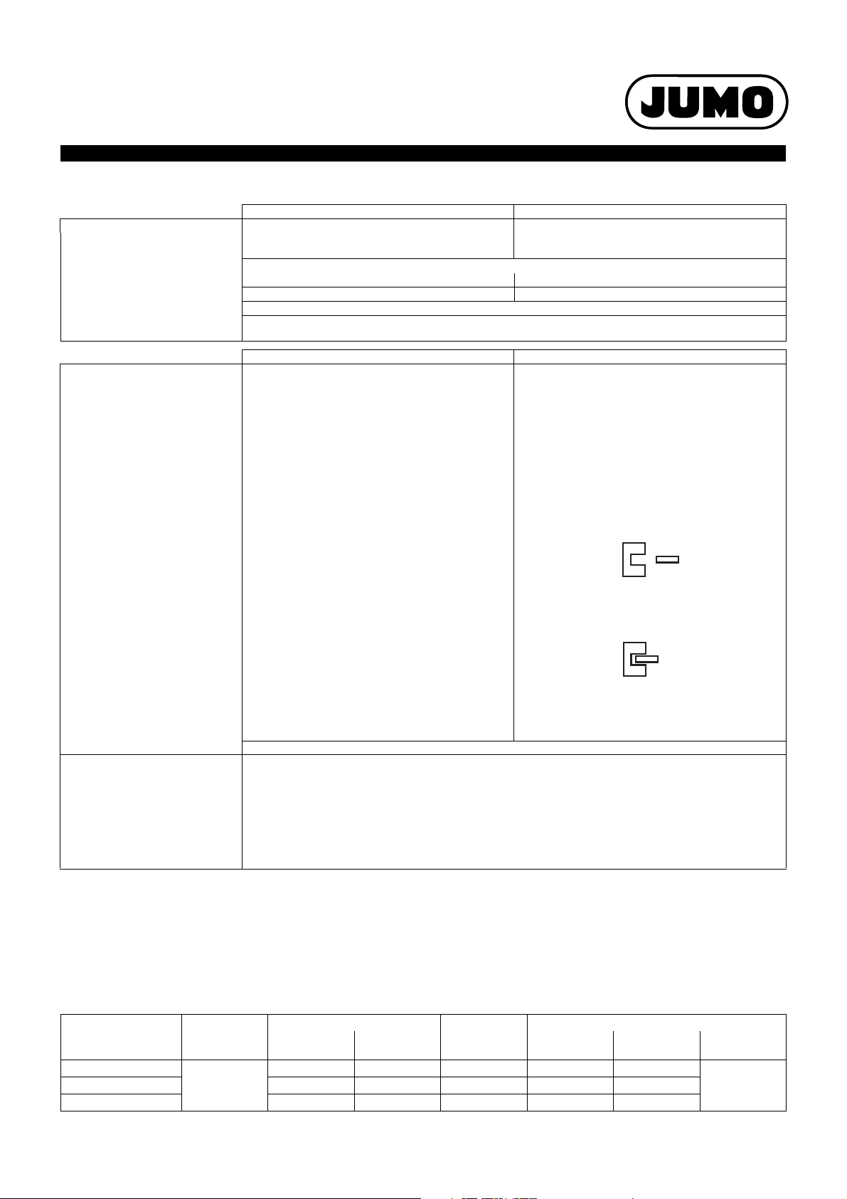
Electromechanical limit contact Inductive limit contact
Switching output 01 to 11 30 and 31
The inductive limit contact is operated by a
contactless proximity switch. The sensor is a slottype initiator attached to the setpoint indicator. The
control flag is activated by the pointer.
If the control flag moves into the sensor gap, the
internal resistance increases (active area is damped:
initiator is high-resistance, relay is de-energized).
The switching amplifier of the control device
responds to the resulting change in current.
Switching action according to the
“active current principle”.
Control flag is not within the sensor air gap, relay is
energized:
(active area is clear, the oscillator is active).
Control flag is within the sensor air gap,
Current drawn ≥ 3mA
Relay is de-energized:
Current drawn ≤ 1mA
(active area is damped, no oscillation).
Inductive limit contact
as per Directive 94/9 EC (ATEX),
suitable for II 2 G EEx ia IIC T6
for switching sequence and diagrams: see order details
Secondary switched devices For electromechanical limit detectors we recommend using Type MSR multi-function relays from:Wiebrock
Mess- und Regeltechnik GmbH, www.wiebrock.de.
These switching amplifiers increase the switching reliability and switching capacity of slow-break and
magnetic snap-action contacts, and reduce their contact loading.
Unintended switching of the limit contact (caused by vibration) can be considerably reduced by using a
drop-out delay.
With inductive limit detectors, you can use the transistor relay:
Type KFA6-SR2-Ex...W (II (1) G D
Intrinsic safety II 2 G EEx ia IIC T6 can only be ensured if this transistor relay is used.
Note:
Physical and toxic features of the expansion means, which could emerge in the event of a measuring system break.
Control range with
scale limit value
< +200°C
Hazardous re-
actions
Fire and explosion hazard hazardous to
Ignition tem-
perature
Explosion limit irritant dangerous to
+ 355°C 0,6 - 8 V% yes yes
no
> 350°C ≤ +500°C no no no no no
1)
There is currently no statement by the health authority concerning hazards to health in the event of short-term exposure and low concentration, e.g. measuring
system break.
2011-11-08/00402234
[EEx ia] IIC) from Pepperl & Fuchs (www.pepperlfuchs.de).
waters
Information about toxicology
health
1)
1)
toxic
no≥ 200°C ≤ +350 °C + 490°C - - yes yes
Page 3

JUMO GmbH & Co. KG
Delivery address: Mackenrodtstraße 14
36039 Fulda, Germany
Postal address:
36035 Fulda, Germany
Phone: +49 661 6003-0
Fax: +49 661 6003-607
E-mail: mail@jumo.net
Internet: www.jumo.net
JUMO Instrument Co. Ltd.
JUMO House
Temple Bank, Riverway
Harlow, Essex CM20 2DY, UK
Phone: +44 1279 635533
Fax: +44 1279 635262
E-mail: sales@jumo.co.uk
Internet: www.jumo.co.uk
JUMO Process Control, Inc.
6733 Myers Road
East Syracuse, NY 13057, USA
Phone: 315-437-5866
1-800-554-5866
Fax: 315-437-5860
E-mail: info.us@jumo.net
Internet: www.jumousa.com
Data Sheet 608425
Dimensions
8
1
1
5
1
1
ØD
74
49.5
L
ØD
H
H
119.5
16Ø
L
S L
8
1
5
1
1
1
2
ØD
74
49.5
L
16
Ø
LS
L
ØD
H
H
119.5
H
1
2
3
1
4
1
1
ØD
ØD
ØD
a
ØD
H
H
ØD +2
164
44
H
3x120
°
Panel cut-out for housing
diameter 100mm = 105.5
+0.5
mm
diameter 160mm = 165.5
+0.5
mm
Types: 608425/0110
608425/0116
Types: 608425/1010
608425/1016
Page 3/6
Types: 608425/2010
608425/2016
1
for lengths, see Data Sheet 608730
2011-11-08/00402234
Page 4

JUMO GmbH & Co. KG
Delivery address: Mackenrodtstraße 14
36039 Fulda, Germany
Postal address:
36035 Fulda, Germany
Phone: +49 661 6003-0
Fax: +49 661 6003-607
E-mail: mail@jumo.net
Internet: www.jumo.net
JUMO Instrument Co. Ltd.
JUMO House
Temple Bank, Riverway
Harlow, Essex CM20 2DY, UK
Phone: +44 1279 635533
Fax: +44 1279 635262
E-mail: sales@jumo.co.uk
Internet: www.jumo.co.uk
JUMO Process Control, Inc.
6733 Myers Road
East Syracuse, NY 13057, USA
Phone: 315-437-5866
1-800-554-5866
Fax: 315-437-5860
E-mail: info.us@jumo.net
Internet: www.jumousa.com
Data Sheet 608425
Types: 608425/2210
8
3
2
1
3
1
2
ØD
ØD
ØD
74
49.5
3x120
°
a
L
ØD
H
H
H
H
13
8
1
1
*
2
ØD
74
49.5
L
b
56
7.4
65
ØD
H
H
119.5
100
28
H
instrument mounting to DIN 16281
* spigot, 26 mm diameter
Fixing bracket width
Panel cut-out 92 x 92 mm
+0.8
0
608425/2216
Types: 608425/2310
608425/2316
Page 4/6
Housing
HH
1
H
H
2
H
3
4
DD1D
D
2
3
abL5L
diameter
100 95 62
160 96 63 121 130 159 161.5 178 196 5.8 82 120
1
for probe mounting TA 02, L5 is ≤ 69 mm.
17.5
129.5 129 99 101.5 116 132 4.8 52
Type: 608425/2496
2011-11-08/00402234
40
8
90
1
Page 5

JUMO GmbH & Co. KG
Delivery address: Mackenrodtstraße 14
36039 Fulda, Germany
Postal address:
36035 Fulda, Germany
Phone: +49 661 6003-0
Fax: +49 661 6003-607
E-mail: mail@jumo.net
Internet: www.jumo.net
JUMO Instrument Co. Ltd.
JUMO House
Temple Bank, Riverway
Harlow, Essex CM20 2DY, UK
Phone: +44 1279 635533
Fax: +44 1279 635262
E-mail: sales@jumo.co.uk
Internet: www.jumo.co.uk
JUMO Process Control, Inc.
6733 Myers Road
East Syracuse, NY 13057, USA
Phone: 315-437-5866
1-800-554-5866
Fax: 315-437-5860
E-mail: info.us@jumo.net
Internet: www.jumousa.com
Data Sheet 608425
Order details
Contact dial thermometers, Class 1, Type 608425
(1) Basic type
608425 Mechanical contact dial thermometer, Class 1 (round, panel- or surface-mounting instrument)
608425 Mechanical contact dial thermometer, Class 1 (square, panel-mounting instrument)
X 0110 Style: 01; housing size: diameter 100 mm
X 0116 Style: 01; housing size: diameter 160 mm
X 1010 Style: 10; housing size: diameter 100 mm
X 1016 Style: 10; housing size: diameter 160 mm
X 2010 Style: 20; housing size: diameter 100 mm
X 2016 Style: 20; housing size: diameter 160 mm
X 2210 Style: 22; housing size: diameter 100 mm
X 2216 Style: 22; housing size: diameter 160 mm
X 2310 Style: 23; housing size: diameter 100 mm
X 2316 Style: 23; housing size: diameter 160 mm
X 2496 Style: 24; housing size: 96 x 96 mm
X X 469 -40 to0 +40°C; range -30 to +030°C Error limit 1.0°C
X X 566 -30 to0 +50°C; range -20 to +040°C Error limit 1.0°C
X X 807 -10 to 0+60°C; range +10 to +050°C Error limit 1.0°C
X X 810 -10 to 0+80°C; range +10 to +070°C Error limit 1.0°C
X X 814 -20 to +100°C; range +10 to +090°C Error limit 1.0°C
X X 818 -20 to +120°C; range +20 to +100°C Error limit 2.0°C
X X 826 -20 to +160°C; range +20 to +140°C Error limit 2.0°C
X X 832 -20 to +200°C; range +20 to +180°C Error limit 2.0°C
X X 834 -30 to +250°C; range +30 to +220°C Error limit 2.5°C
X X 840 -30 to +300°C; range +30 to +270°C Error limit 5.0°C
X X 843 -50 to +350°C; range +50 to +300°C Error limit 5.0°C
X X 848 -50 to +400°C; range +50 to +350°C Error limit 5.0°C
X X 854 -50 to +500°C; range +50 to +450°C Error limit 5.0°C
X 00 none (with rigid stem)
X X 04 FL04 capillary, stainless steel (1.4571), diameter 2.2 mm
X X 0000 none (rigid connection)
X X 1000 1000 mm
X X 2000 2000 mm
X X 3000 3000 mm
X X 4000 4000 mm
X X 5000 5000 mm
X X . . . . special length (specify in plain text: 1000 mm steps, maximum length 10000 mm)
X X 750 TF01 temperature probe with shoulder on support tube
X X 753 TF05 temperature probe with plain support tube
X X 752 TF11 temperature probe without support tube
X X 843 TA02 stem with union nut and loose nipple (only TF01)
X X 161 TA03/01 stem with loose union nut (with TF01)
X X 846 TA04 stem with fixed hexagon screw-in spigot (only TF01)
X X 847 TA06 sliding clamp fitting on support tube
X X 891 SH05 screw-in pocket, assembled 2 (with 14 mm dia. only)
X X 913
(2) Basic type extensions
(3) Indication range (AB)
(4) Capillary type (FL)
(5) Capillary length
(6) Process connection (PA)
1
1
1
2
2
2
SH07 screw-in pocket, assembled, with clamping clip and fixing screw
2
Page 5/6
2011-11-08/00402234
Page 6

JUMO GmbH & Co. KG
Delivery address: Mackenrodtstraße 14
36039 Fulda, Germany
Postal address:
36035 Fulda, Germany
Phone: +49 661 6003-0
Fax: +49 661 6003-607
E-mail: mail@jumo.net
Internet: www.jumo.net
JUMO Instrument Co. Ltd.
JUMO House
Temple Bank, Riverway
Harlow, Essex CM20 2DY, UK
Phone: +44 1279 635533
Fax: +44 1279 635262
E-mail: sales@jumo.co.uk
Internet: www.jumo.co.uk
JUMO Process Control, Inc.
6733 Myers Road
East Syracuse, NY 13057, USA
Phone: 315-437-5866
1-800-554-5866
Fax: 315-437-5860
E-mail: info.us@jumo.net
Internet: www.jumousa.com
Data Sheet 608425
Order details
PE
L1
I
PE L1
I
PE L1
III
PE L1
III
PE L1
III
PE L1 L1
III
PE L1 L1
III
PE
I
PE
I
Contact dial thermometers, Class 1, Type 608425
(7) Diameter of process connection (PA)
XX 06diameter 06mm
XX 08diameter 08mm
X X 100 diameter 10 mm
X X 140 diameter 14 mm (only SH05)
(8) Thread for process connection (PA)
X X 000 no thread (with TF01, TF05 and TF11)
X X 103 thread G 3/8
X X 104 thread G 1/2
X X 105 thread G 3/4
(9) Process connection (PA) material
X X 26 stainless steel (CrNi, 1.4571)
X X 97 stainless steel (CrNi, 1.4571)-TF / brass (CuZn)-TA, SH
(10)
Fitting length of process connection (PA)1 (dimension "EL" or "S")
XX 00 minimum fitting length TF 11 (active probe dimension)
XX 050 050 mm
X X 100 100 mm
X X 150 150 mm
X X 200 200 mm
X X . . .
special length (specify in plain text, steps of 50 mm)
(11)
Switching output (SA)
1
1
1
Page 6/6
X X 01 With rising temperature: contact 1 opens (2)
X X 02 With rising temperature: contact 1 closes (1)
X X 03 With rising temperature: contact 1 opens and
X X 04 With rising temperature: contact 1 and
X X 05 With rising temperature: contact 1 opens and
X10
X 11 With rising temperature: contact 1 and contact 2 close
X X 30 With rising temperature:
X X 31 With rising temperature:
X X 000 no extra code
X X 442 electromechanical magnetic snap-action contact
X 509 setpoint adjustment with key
X X 522 customized scale
Order code
(1) (2) (3) (4) (5) (6) (7) (8) (9) (10) (11) (12)
608425 / . . . . - . . . - . . - . . . . - . . . - . . - . . . - . . - . . . - . . . / . . . ,. . .
Order example
608425 / 2010 - 818 - 04 - 2000 - 750 - 8 - 000 - 26 - 100 - 01 / 000
1
for description and features, see Data Sheet 608730
2
screw-in spigot to DIN 3852 Form A
3
figures in brackets ( . . ) correspond to the designation of the switching function code as per DIN 16196
4
list extra codes in sequence, separated by a comma
2011-11-08/00402234
contact 2 closes (21)
contact 2 close (11)
contact 2 opens (22)
With rising temperature: contact 1 opens and
contact 2 closes (with separate circuit) (21)
(with separate circuits) (11)
flag moves in, break action (2)
flag moves out, make action (1)
(12)
Extra codes (TZ)
3
3
3
3
3
3
3
3
3
Special versions on request!
4
,. . .
 Loading...