

Page 1
EM
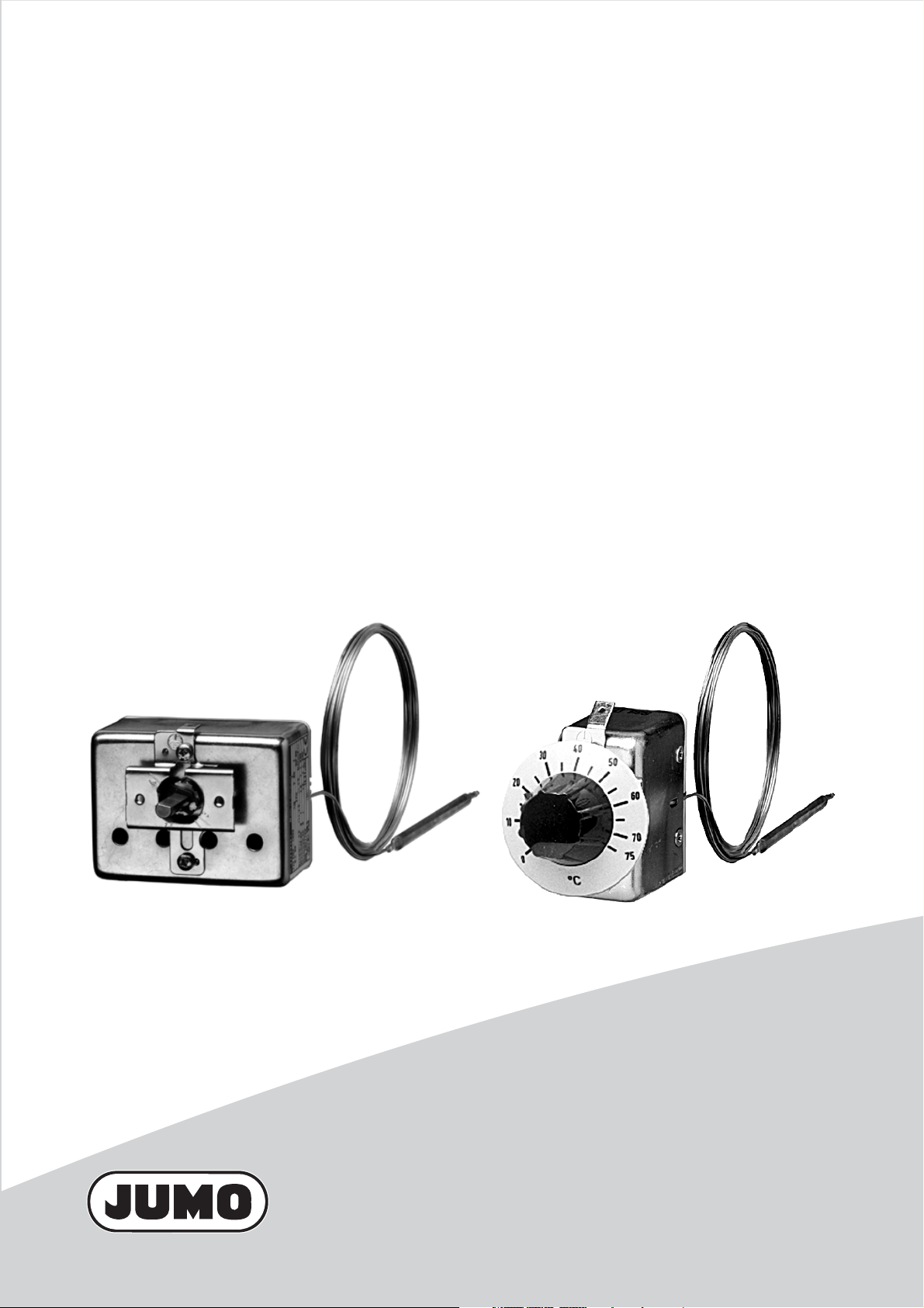
Panel-mounting thermostats
B 602021.0
Operating manual
2013-03-18/00073772
Page 2

Please read these Operating Instructions before commissioning the instrument.
Keep the manual in a place that is accessible to all users at all times. Please
assist us to improve these operating instructions, where necessary. Your comments will be appreciated.
Phone+49 661 6003-0
Fax+49 661 6003-607
All necessary settings and possible adjustments inside the instrument are
described in these operating instructions. If any problems should still arise
during start-up, you are asked not to carry out any unauthorized manipulations
on the unit. You could endanger your rights under the instrument warranty!
Please contact the nearest subsidiary or the head office in such a case.
Page 3

Contents
1 Introduction .................................................................................. 4
1.1 Typographical conventions ......................................................................... 4
1.1.1 Warning signs ................................................................................................. 4
1.1.2 Note signs ...................................................................................................... 4
1.2 Application .................................................................................................... 5
1.3 Marking ......................................................................................................... 5
1.4 Safety notes .................................................................................................. 6
2 Instrument identification ............................................................. 7
2.1 Type nameplate ............................................................................................ 7
2.2 Type designation .......................................................................................... 8
3 Mounting ...................................................................................... 9
3.1 Dimensions ................................................................................................... 9
3.2 Fixing the panel-mounting thermostat ..................................................... 11
3.2.1 Mounting the switch head ............................................................................ 11
3.3 Capillary / temperature probe / pocket .................................................... 13
3.3.1 General ......................................................................................................... 13
3.3.2 Approved probes or pockets ....................................................................... 13
3.4 Permissible loading on the pocket ........................................................... 14
3.4.1 Pockets 20, 22/23, 40 and 41/42 ................................................................. 14
4 Installation .................................................................................. 18
4.1 Regulations and notes ............................................................................... 18
4.2 Electrical connection ................................................................................. 18
4.3 Connection diagrams ................................................................................. 20
5 Settings ....................................................................................... 21
5.1 Unlocking the operating temperature limiter (TB)
or protection temperature limiter (STB) ................................................... 21
5.2 Setpoint adjustment ................................................................................... 22
5.3 Self-monitoring on the STB and STW (STB) ............................................ 22
5.4 Use of the STW (STB) as STB .................................................................... 22
6 Instrument description .............................................................. 23
6.1 Technical data ............................................................................................. 23
Page 4

1 Introduction
1.1 Typographical conventions
1.1.1 Warning signs
V
Danger
This symbol is used when there may be danger to personnel if the
instructions are ignored or not followed correctly!
Caution
A
1.1.2 Note signs
H
v
1
abc
This symbol is used when there may be damage to equipment if the
instructions are ignored or not followed correctly!
Note
This symbol is used when your special attention is drawn to a remark.
Reference
This symbol refers to further information in other chapters or sections.
Footnote
Footnotes are remarks that refer to specific points in the text. Footnotes
consist of two parts:
A marker in the text, and the footnote text.
The markers in the text are arranged as continuous superscript numbers.
The footnote text (in smaller typeface) is placed at the bottom of the page and
starts with a superscript number.
✱ Action instruction
This symbol indicates that an action to be performed is described.
The individual steps are marked by this asterisk, e.g.
✱ Open housing
4
Page 5

1.2 Application
Thermostats control and monitor thermal processes.
Panel-mounting thermostats operate on the principle of liquid or gas
expansion. A microswitch serves as the electrical switching device.
The devices of the EM model series can be supplied as temperature
controllers TR, operating temperature limiters TW, operating temperature
limiters TB, protection temperature limiters STW and protection temperature
limiters STB.
In case of faults, the STB switches the plant that it is monitoring into an
operationally safe state.
Versions to: DIN EN 14597
TR Temperature controller
TW Operating temperature limiter
TB Operating temperature limiter
STW(STB) Protection temperature limiter
STB Protection temperature limiter
1 Introduction
Type approval according to:
- DIN EN 14597
- Pressure Equipment European Directive 97/23/EC
- VDE 0631
-UL
- CSA (only Type EM-1, EM-2, EM-4, EM-50)
You will find the Declarations of Conformity at:
www.jumo.net ➯ Products ➯ Thermostats ➯ Data Sheet 602021
or ask for them to be sent.
Cutting through or kinking the capillary of the panel-mounting thermostat, EM
A
series, will lead to permanent instrument failure!!
1.3 Marking
(only Type EM-20, EM-30, EM-40, EM-50)
Depending on the version:
(see nameplate for details)
5
Page 6

1 Introduction
1.4 Safety notes
Filling liquid may escape in the event of a measuring system fracture.
H
At present, any health risks can be excluded.
Physical and toxicological properties of the expansion fluid that may escape in
the event of a system fracture.
Control range
with
end of scale
°C
< +200 no +355 0.6 - 8 yes yes
ⱖ +200 ≤ +350 no +490 - - yes yes
> +350 ≤ +500 no no no no no no no
Dangerous
reactions
1
concerning any danger to health over short periods and at low concentration,
e.g. after a fracture of the measuring system.
temperature
At present, there is no restrictive statement from the health authorities
Fire and
explosion hazard
Ignition
°C
Explosion
limit
% v/v
Water
contamination
irritant
Toxicological data
danger
to health
1
1
toxic
no
no
6
Page 7
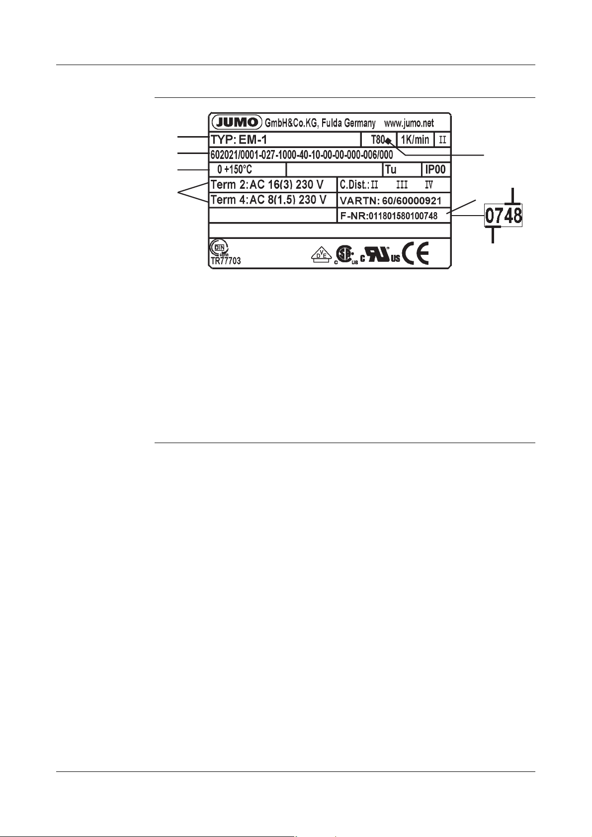
2.1 Type nameplate
( 5 )
( 3 )
( 8 )
( 7 )
( 4 )
( 2 )
( 1 )
( 6 )
( 1 ) Type
( 2 ) Type code
( 3 ) Regulating or limit value range / ambient temperature
at which this thermostat was calibrated (Option)
( 4 ) Switching capacity
2 Instrument identification
( 5 ) Permissible ambient temperature
( 6 ) Serial number
( 7 ) Date of manufacture
( 8 ) Week of manufacture
7
Page 8

2 Instrument identification
2.2 Type designation
Type
designation
EM - .. - .. / .. Panel-mounting thermostat with one
EMF - .... - .. / .. Panel-mounting thermostat with 2, 3 or 4
- 1... Temperature controller TR with changeover
- 2... Operating temperature limiter TW with
- 3... Operating temperature limiter TW with
- 4... Operating temperature limiter TB with NC
microswitch
microswitches
Standard connection "10"
(plain cylindrical probe)
contact
changeover contact
changeover contact; Changeover contact
setting fixed at the factory
contact and restart inhibit; Changeover contact
setting fixed at the factory
- 5... Operating temperature limiter TB with NC
contact and restart inhibit
- 20 Protection temperature limiter STW (STB) with
changeover contact
- 30 Protection temperature limiter STW (STB) with
changeover contact; Changeover contact
setting fixed at the factory
- 40 Protection temperature limiter STB with NC
contact and restart inhibit; Changeover contact
setting fixed at the factory
- 50 Protection temperature limiter STB with NC
contact and restart inhibit
- .... - .. / 707 Temperature compensation at switch head
- .... - .. / 702 Snap-action switch contacts gold-plated
- .... - .. / 574 Microswitch with n.c. (break) contact, lock-out
and additional signal contact (TB and STB only)
8
Page 9
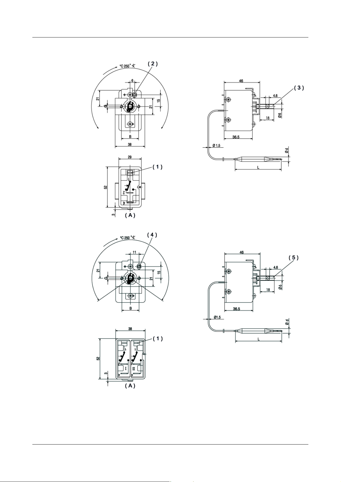
3.1 Dimensions
EM-1
3 Mounting
EMF-13
( 1 ) Faston connector A 6.3 x 0.8 to DIN 46 244
( 2 ) Reset button (with codes 4 and 5 only)
( 3 ) omitted with codes 2, 3, 4 and 5
( 4 ) Reset button (with codes 4, 5, 40 and 50 only)
( 5 ) omitted with codes 2, 3, 4, 5, 20, 30, 40, 50
( A ) Rear view
9
Page 10

3 Mounting
EMF-133
EMF-1333
10
( 1 ) Faston connector A 6.3 x 0.8 to DIN 46 244
( 2 ) Reset button (with codes 4 and 5 only)
( 3 ) omitted with codes 2, 3, 4 and 5
( 4 ) Reset button (with codes 4, 5, 40 and 50 only)
( A ) Rear view
Page 11

3.2 Fixing the panel-mounting thermostat
( 1 )
( 1 )
( 2 )
( 1 )
( 1 )
( 2 )
3 Mounting
Operating
position
unrestricted
3.2.1 Mounting the switch head
Type EM.-1... by two M3 screws
(M4 with extra code 704)
on chassis:
(1) Screw
(2) Panel
Extra
code
Series 3.5 22
704 4.5 28
705 3.5 33
Dim. (mm)
GB
Type EM.-2... ,
-3... , -4... , -5... ,
-20, -30, -40 or
-50
by two M3 screws
(M4 with extra code 704)
on chassis:
(1) Screw
(2) Panel
Type Dim. (mm)
XY
EM-2, -3,
-20, -30
EM-4, -5,
EM-40,
-50
EMF-44,
-54
EMF-444,
-544
EMF-5444 27
Dimensions B and G, see above
- - - -
11
15
11
19
6
11
Page 12

3 Mounting
( 1 )
( 2 )
( 3 )
( 4 )
Type EM.-4, -5,
-40 or -50
central fixing
(extra code 710)
( 1 ) Panel
(2) Fixing nut
M10 x 1 (13 a/f)
(3) Cap nut M10 x 1
(10 a/f)
(4) Reset button
Type Dim. (mm)
XY
EM-4, -5
EM-40, -50, 11
16
6
12
Page 13

3.3 Capillary / temperature probe / pocket
(B)
(C)
3.3.1 General
Cutting through or kinking the capillary of the panel-mounting thermostat will
A
lead to permanent instrument failure!
Minimum permissible bending radius of the capillary is 5 mm.
The temperature probe must be mounted in a JUMO pocket, otherwise the
approval of the panel-mounting thermostat becomes invalid.
The temperature probe must be completely immersed in the medium to be
measured. The temperature probe or protection tube must not come into
contact with the walls of the container or pipe.
To ensure their overall accuracy, the thermostats must only be used together
with the pockets supplied by the factory (diameter D = 8 or D = 10 mm).
Pockets with diameter D = 10 mm may only be fitted with probes with
diameter d = 8 mm.
Fitting several probes into a common pocket is permissible with 2 or 3
cylindrical probes with diameter D = 6 mm and pockets 15 x 0.75 mm.
When fitting 2 probes in a common pocket, the factory-supplied spring clip
must be fitted in the pocket.
3 Mounting
For operation in air, probe mounting type “10” (without pocket) must be
chosen.
In the case of pockets 22, 41, 42 and 45, in materials St35.8 I, the permissible
operating life at operating temperatures above +420°C is limited to 200,000
hours. The requirements of TRD 508 must be observed for operation in this
range.
( B ) Immersion tube
( C ) Temperature probe
3.3.2 Approved probes or pockets
refer to data sheet 606710 !
13
Page 14

3 Mounting
3.4 Permissible loading on the pocket
3.4.1 Pockets 20, 22/23, 40 and 41/42
The values given below refer to the maximum loading on the probe mounting
A
3.4.1.1 Steel pockets 22, 23, 32, 41, 42 and 45
Materials Tube: St35.8 I
Loading
concerned. The maximum pressure which can be sealed depends on the
mounting conditions and may possibly be lower.
Screw-in nipple up to 300°C: Steel 1.0038
Weld-in nipple: Steel 1.5415
Tube diameter D
Te mp er at ur e
100°C 89 bar 72 bar 48 bar
150°C 83 bar 67 bar 45 bar
200°C 78 bar 63 bar 42 bar
300°C 59 bar 47 bar 32 bar
350°C 50 bar 40 bar 27 bar
8 x 0.75 mm
or conical
Max. permissible pressure
10 x 0.75 mm 15 x 0.75 mm
14
Page 15

Permissible
incident flow
velocity
3 Mounting
Material: St35.8 I
Temperature: +200°C
Thermal medium:
Tube diameter D:
Permissible incident flow velocity (m/sec) at the maximum permissible
pressure loading and different immersion tube lengths “S”.
air ( 1 )
water, oil ( 2 )
. . . . . . . . . . . . . .
08mm
10 mm
15 mm
( 1 ) Air
( 2 )
Water, oil
Permissible incident flow velocity (m/sec) at the maximum permissible
pressure loading and different immersion tube temperatures “t”.
Material: St35.8 I
Immersion tube length “s”:
Thermal medium:
Tube diameter D:
200 mm
air
water, oil
. . . . . . . . . . . . . .
08mm
10 mm
15 mm
( 1 ) Air
( 2 )
Water, oil
15
Page 16

3 Mounting
3.4.1.2 Stainless steel pockets 20, 22, 40 and 41/42
Loading
Material of tube and nipple: stainless steel (1.4571)
Tube diameter D
Te mp er at ur e
100°C 92 bar 74 bar 50 bar
150°C 88 bar 71 bar 48 bar
200°C 83 bar 67 bar 45 bar
300°C 72 bar 58 bar 39 bar
400°C 67 bar 54 bar 36 bar
3.4.1.3 Brass pockets 20 and 40
Loading
Te mp er at ur e
100°C 50 bar 40 bar 27 bar
8 x 0.75 mm
or conical
Max. permissible pressure
Material of tube and nipple: CuZn
8 x 0.75 mm 10 x 0.75 mm 15 x 0.75 mm
Max. permissible pressure
10 x 0.75 mm 15 x 0.75 mm
Tube diameter D
150°C 48 bar 39 bar 26 bar
16
Page 17

3.4.1.4 Probe mountings 50, 52 and 54
( 1 )
( 2 )
Nipple material CuZn steel stainless steel (1.4571)
Temperature °C 200 300 400
3 Mounting
A
H
Probe material Ø
Cu-DHP
St35 / 1.4571 4 - 10 10 bar 2 bar
Forms 10, 15, 21, 60, 65 may only be used in unpressurized media.
The temperature probe (2) must be immersed in the medium for its entire
length, otherwise there will be appreciable deviations from the switching point.
In the case of probe mountings 20, 22/23 and 21, the temperature probe is
secured in the pocket by a clamping clip (1).
mm
TR, TW, TB STB, STW (STB)
46 bar
55 bar
64 bar
73 bar
83 bar
93 bar
10 3 bar
Thermostat action
2 bar
17
Page 18

4 Installation
4.1 Regulations and notes
■ The electrical connection must only be carried out by qualified personnel.
■ The choice of cable, the installation and the electrical connection must
conform to the requirements of VDE 0100 “Regulations on the Installation
of Power Circuits with Nominal Voltages below 1000 V” or the appropriate
local regulations.
■ If contact with live parts is possible while working on the instrument, it must
be completely disconnected from the electrical supply.
■ Earth the instrument at the PE terminal to the protective earth conductor.
This cable must have at least the same cross-section as used for the supply
cables. Earthing cables must be wired in a star configuration to a common
earth point that is connected to the protective earth conductor of the
electrical supply. Do not loop earthing cables, i.e. do not run them from one
instrument to another.
■ Apart from faulty installation, incorrect settings on the thermostat may also
affect the proper functioning of the subsequent process or lead to damage.
Setting up must therefore be restricted to qualified personnel. Please
observe the relevant safety regulations for such matters.
4.2 Electrical connection
■ Terminals and connections are suitable for internal conductors
■ The connection is suitable for fixed wiring.
■ Cable entry without strain relief
■ The thermostat conforms to Protection Class I.
Capillary tube has no protective conductor function!
With respect to the probe and capillary, the user himself is responsible for
taking the necessary protective measures against electric shock.
18
Page 19

Plug connection
( 1 )
2
1
(standard)
4 Installation
( 1 ) = faston connector A 6.3 x 0.8 to DIN 46 244
Screw
connection
(extra code 699)
( 1 ) Receptacle 6.3 with connection screw, suitable for conductor cross-
2
sections up to 2.5 mm
( 2 ) Terminal strip
; attachment type X, no special tools
19
Page 20

4 Installation
4.3 Connection diagrams
EM-1
EM-2
EM-3
EMF-13
EMF-23
EMF-33
Setpoint: I
Follow-on contact:
II
EMF-133
EMF-233
EMF-333
Setpoint: I
Follow-on contact:
II, III
EMF-1333
EMF-2333
EMF-3333
Setpoint: I
Follow-on contact:
II, III, IV
EM-4
EM-5
EM-4/574
EM-5/574
EM-40
EM-50
n.c. (break)
contact
on measuring
system failure
and T
limit: II
EM-40/574
EM-50/574
< -10 °C: I
EM-20
EM-30
n.c. (break)
contact
on measuring
system failure
and T
limit: II
Example: EMF-1334 For other variants, the connection
diagrams are combined appropriately.
< -10 °C: I
20
Page 21

5 Settings
5.1 Unlocking the operating temperature limiter (TB)
or protection temperature limiter (STB)
EM-4
EMF-4...
EM-5
EMF-5...
EM-40
EM-50
with fixing
bracket 704,
705
After the temperature has dropped by about 10% of span below the set limit
(critical temperature), the microswitch can be reset.
EM-4
EMF-4...
EM-5
EMF-5...
EM-40
EM-50
with central
fixing 710
✱ Push the reset button using a small screwdriver
✱ Unscrew cap
✱ Press reset button
✱ Screw cap back into position
21
Page 22

5 Settings
°C
(1)
(2)
(3)
(4)
°C
(1)
(2)
(3)
5.2 Setpoint adjustment
EM-1
EMF-1...
EM-2
EMF-2...
EM-5
EMF-5...
EM-20
EM-50
( 1 ) Setpoint marker
( 2 ) External scale
( 3 ) Setpoint knob
( 4 ) Scale graduation
✱ Rotate the setpoint knob by hand over the
external scale
( 1 ) Setpoint spindle
( 2 ) Scale graduation
( 3 ) Setpoint marker
✱ Rotate the setpoint spindle over the internal
scale using a screwdriver
EM-3
EMF-3...
EM-4
EMF-4...
EM-30
EM-40
H
The limit setting is fixed at the factory and sealed.
It must subsequently not
be adjusted.
5.3 Self-monitoring on the STB and STW (STB)
If the measuring system fails, i.e. if the expansion liquid has leaked, then the
H
pressure under the diaphragm drops and the circuit is permanently open. It is
no longer possible to reset the system.
When the temperature at the probe falls below approx. -20 °C, the circuit is also
opened, but will close again automatically when the temperature rises above
-10 °C.
5.4 Use of the STW (STB) as STB
V
The lock-out facility to DIN EN 14597 must be ensured by the subsequent
circuit. This circuit must comply with VDE 0116.
22
Page 23

6.1 Technical data
Permissible
ambient
temperature
max. see nameplate
6 Instrument description
Capillary Switch head
TB,
TR,TW
STW(STB)
STB
TR,TW
TB,
STW(STB)
STB
for end of scale
-40 °C
min.
Permissible
probe
temperature
Permissible
storage
temperature
Housing galvanized steel sheet
Switching
device
max.: end of scale / limit value +15%,
min.: -50 °C (on STW(STB) and STB -35 °C)
max. +50 °C, min. -50 °C
Type EM-.... Description
1, 2, 3, 20, 30
4, 5, 40, 50 with n.c. (break) contact
4/574, 5/574, 40/574,
50/574
-20 °C ≥ 200 °C ≤ 350 °C
-40 °C > 350 °C ≤ 500 °C
(for end of scale between +90 °C and 120 °C = min. 25 °C
< 200 °C
-20°C -20°C 0°C
1, 2, 3 or 4 single-pole snap-action switches
with changeover contact
n.c. (break) contact with additional signal contact
23
Page 24

6 Instrument description
Contact rating
Switching
Type EM-...
1, 2, 3, 20, 30
4, 5, 40, 50 - - - -
1, 2, 3, 20, 30
1, 2, 3, 20, 30 1 / 3
4, 5, 40, 50 - -
4/574, 5/574,
40/574, 50/574
Contact reliability
To ensure maximum switching reliability, we recommend a minimum load of:
- AC / DC 24 V, 100 mA with silver contacts (standard)
differential
2.5 / 5 /7 /
2.5 / 5 / 6 /
7 / 10
%
10
- -
Current
Terminal 2 Terminal 4
10 A
16(3) 8(1.5) A
0.25 A 0.25 A 230 V DC +10%
6(2)
0.25 A 230 V DC +10%
16(3) A
0.25 A 230 V DC +10%
0.1 A extra
code “702”
16(3) A 2(1) A
0.25 A 230 V DC +10%
0.1 A extra code “702” 24 V AC/DC
2A
- -
Voltage
400 V AC +10%
230 V AC +10%
p.f. = 1 (0.6)
230 V AC +10%
p.f. = 1 (0.6)
230 V AC +10%
p.f. = 1 (0.6)
24 V AC/DC
230 V AC +10%
p.f. = 1 (0.6)
- AC / DC 10 V, 5 mA in case of gold-plated contacts (extra code "702")
Rated surge voltage
2500 V (via the connecting contacts 400 V)
Overvoltage category II
Fusing required
see current rating
24
Page 25

6 Instrument description
Switching point
accuracy
Protection EN 60 529 - IP00
(in % of scale span; referred to setpoint or limit value
at T
+22 °C, with rising temperature)
A
Switching differential in % Switching point accuracy in %
Type EM-...
11 / 2.5
2, 3
4, 4/
574
,
574
5, 5/
20, 30 7
40, 40/574,
50, 50/574
Pollution degree 2
liquid-filled gas-filled
- 5
7
1 / 2.5
5
7
- - - - +0 / -5 +0 / -7
- -
3 / 5
6 / 10
- -
3 / 5
6 / 10
10
- -
in upper third of
scale or at limit
± 1.5
± 3,5
± 4,5
+ 0 / - 3
+ 0 / - 6
+ 0 / - 8
+0 / -8 + 0 / - 10
at start of scale
± 4
± 5
± 6
+ 0 / - 5
+ 0 / - 8
+ 0 / - 10
Operating
medium
Time constant
t
0.632
Mode of
operation
water, oil, air, superheated steam
in water in oil in air / superheated
steam
≤ 45 sec ≤ 60 sec ≤ 120 sec
as per EN 60 730-1, DIN EN 60 730-2-9 and DIN EN 14597
TR, TW 2 BL
TB 2 BFHLPV
STW(STB): 2 BKLNP
STB 2 BFHKLNPV
Explanation of codes:
2 mode of operation type 2
B automatic mode of operation with micro-disconnection
F can only be reset with tools
H free-release mechanism, contacts cannot be prevented from opening
K with probe break protection
L no auxiliary power required
P mode of operation type 2, verified through declared temperature cycling
V lockout
25
Page 26

6 Instrument description
Nominal
position
Weight approx. 0.2 kg
Capillary and
probe material
unrestricted
End of scale Capillary Probe
up to +200 °C copper, Mat. Ref. Cu-DHP
up to +350 °C copper, Mat. Ref. Cu-DHP
up to +500 °C stainless steel,
up to +350 °C stainless steel,
1.5 mm diameter
1.5 mm diameter
1.5 mm diameter
at extra cost
1.5 mm diameter
copper, Mat. Ref. Cu-DHP
brazed
stainless steel,
Mat. Ref. 1.4571
brazed
stainless steel,
Mat. Ref. 1.4571
welded
stainless steel,
Mat. Ref. 1.4571
welded
Minimum
bending radius
of capillary
Mean
ambient
temperature
error
< +200 °C ≥ +200 °C ≤ +350 °C ≥ +400 °C ≤ +500 °C
TR, TW, TB STW
1 / 2.5 5 7 7 / - - 1 / 2.5 5 7 / - - 3.5 6 10
0.15 0.26 0.34 0.43 0.12 0.21 0.35 0.12 0.17 0.24
5mm
in % of scale span, referred to the limit value.
A deviation of the ambient temperature at the switch head and/or the capillary
from the +22 °C calibration ambient temperature produces a shift in the
switching point:
higher ambient temperature = lower switching point
lower ambient temperature = higher switching point
For temperatures with end of scale / limit value
TR, TW, TB STW, STB TR, TW, TB
STB
Switching differential in %
Ambient temperature effect due to the switch head, % per °C
STW, STB
0.05 0.09 0.04 0.07 0.05
Temperature
compensation
(extra code 707)
26
Ambient temperature effect due to the capillary, % per °C per meter
Please see the diagram in Data Sheet 602021 for details.
Page 27

Page 28

JUMO GmbH & Co. KG JUMO Instrument Co. Ltd. JUMO Process Control, Inc.
Street address:
Moritz-Juchheim-Straße 1
36039 Fulda, Germany
Delivery address:
Mackenrodtstraße 14
36039 Fulda, Germany
Postal address:
36035 Fulda, Germany
Phone: +49 661 6003-0
Fax: +49 661 6003-607
E-mail: mail@jumo.net
Internet: www.jumo.net
JUMO House
Temple Bank, Riverway
Harlow - Essex CM20 2DY, UK
Phone: +44 1279 63 55 33
Fax: +44 1279 63 52 62
E-mail: sales@jumo.co.uk
Internet: www.jumo.co.uk
6733 Myers Road
East Syracuse, NY 13057, USA
Phone: 315-437-5866
1-800-554-5866
Fax: 315-437-5860
E-mail: info.us@jumo.net
Internet: www.jumousa.com
 Loading...