

Page 1

SC-920
INSTRUCTION MANUAL
Page 2

CONTENTS
I. SPECIFICATIONS ........................................................................................ 1
II. SET-UP ........................................................................................................ 1
1. Changing over the voltage between 100 V and 200 V ......................................................................... 2
2. Installing to the table .............................................................................................................................. 3
3. Installing the control panel .................................................................................................................... 5
4. Connecting the cords ............................................................................................................................. 6
5. Attaching the connecting rod ..............................................................................................................12
6. Setting procedure of the machine head ............................................................................................. 13
7. Adjusting the machine head (direct-drive motor type sewing machine only) ................................14
III. FOR THE OPERATOR ............................................................................. 15
1. Operating procedure of the sewing machine .....................................................................................15
2. Operation panel (CP-18) ....................................................................................................................... 17
3. Operating procedure of the sewing pattern ....................................................................................... 18
(1) Reverse feed stitching pattern .............................................................................................................. 18
(2) Overlapped stitching pattern ................................................................................................................ 19
4. One-touch setting ................................................................................................................................. 20
5. Production support function ...............................................................................................................21
6. Setting of functions of SC-920 ............................................................................................................24
7. Function setting list ..............................................................................................................................25
8. Detailed explanation of selection of functions .................................................................................. 29
9. Automatic compensation of neutral point of the pedal sensor ........................................................ 39
10. Selection of the pedal specications ..................................................................................................39
11. Setting of the auto lifter function ........................................................................................................40
12. Selecting procedure of the key-lock function .................................................................................... 41
13. Connection of the pedal of standing-work machine .........................................................................41
14. External input / output connector .......................................................................................................42
15. Connection of the material end sensor ..............................................................................................43
16. Initialization of the setting data ........................................................................................................... 44
IV. MAINTENANCE ....................................................................................... 44
1. Removing the rear cover......................................................................................................................44
2. Replacing the fuse ................................................................................................................................ 45
(1) PWR PCB ................................................................................................................................................ 45
(2) CTL PCB .................................................................................................................................................. 46
3. Error codes............................................................................................................................................46
i
Page 3
I. SPECIFICATIONS
Supply voltage Single phase 100 to 120V 3-phase 200 to 240V Single phase 220 to 240V
Frequency 50Hz/60Hz 50Hz/60Hz 50Hz/60Hz
Operating envi-
ronment
Input 320VA 320VA 320VA
* The power consumption values shown in the above table are reference values in the case the main body of
the sewing machine used with the SC-920 is DDL-9000B.
The power consumption differs with the machine head to be selected.
Temperature : 0 to 40˚C
Humidity : 90% or less
Temperature : 0 to 40˚C
Humidity : 90% or less
Temperature : 0 to 40˚C
Humidity : 90% or less
II. SET-UP
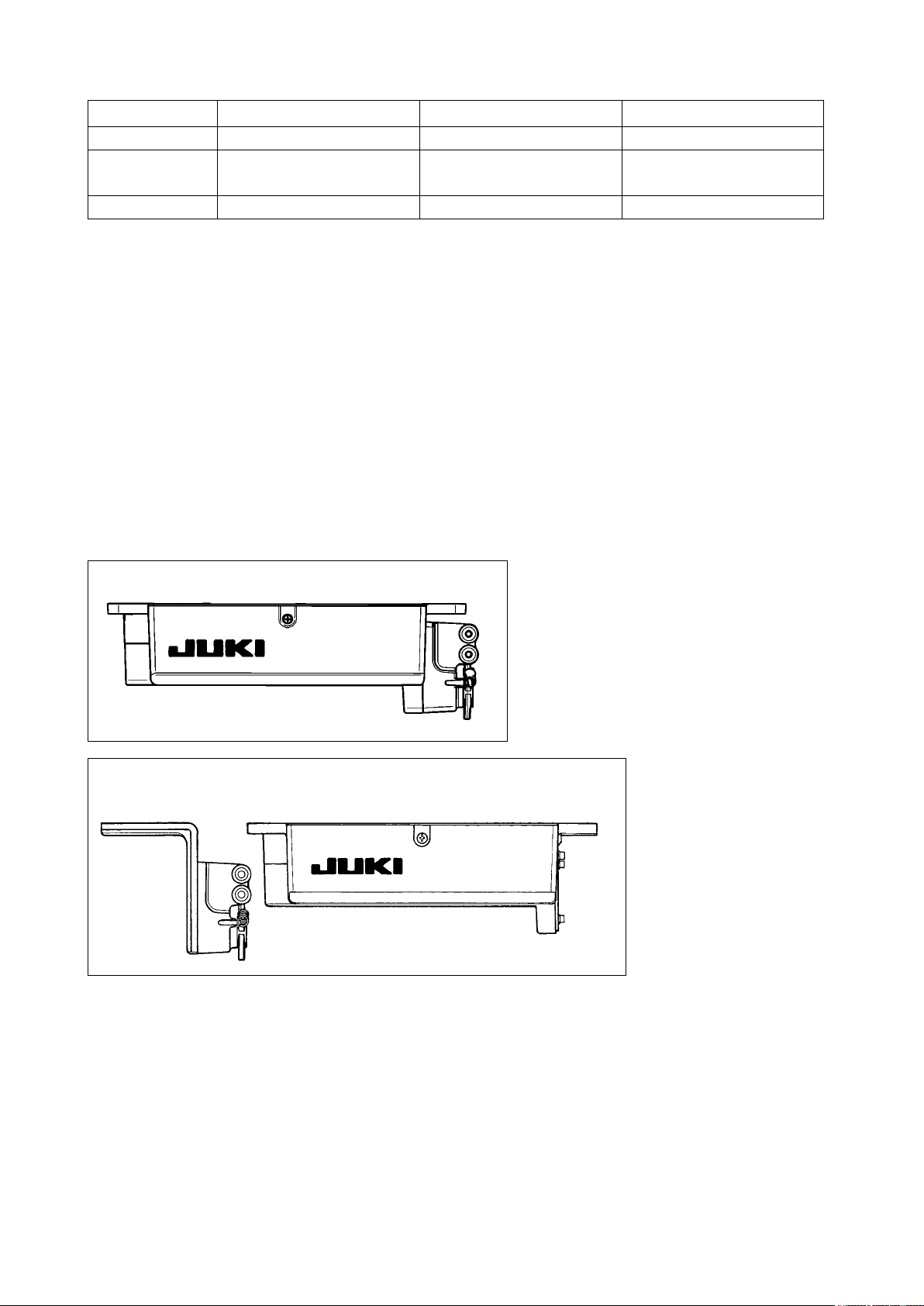
SC-920 is a discrete control box and can be used with the DD (direct-drive) system sewing machine head.
To use a compact motor unit, the motor unit has to be installed on the table in prior to the installation of the con-
trol box on it. To connect the SC-920 to a compact motor, assemble them referring to "M92 SUPPLEMENTARY
SETUP INSTRUCTIONS".
In the case the SC-920 is used for the DD (direct-drive) type sewing machine head, install the control box on the
table following the instructions give below.
SC-920 control box
SC-920 control box (For installing the compact motor)
– 1 –
Page 4
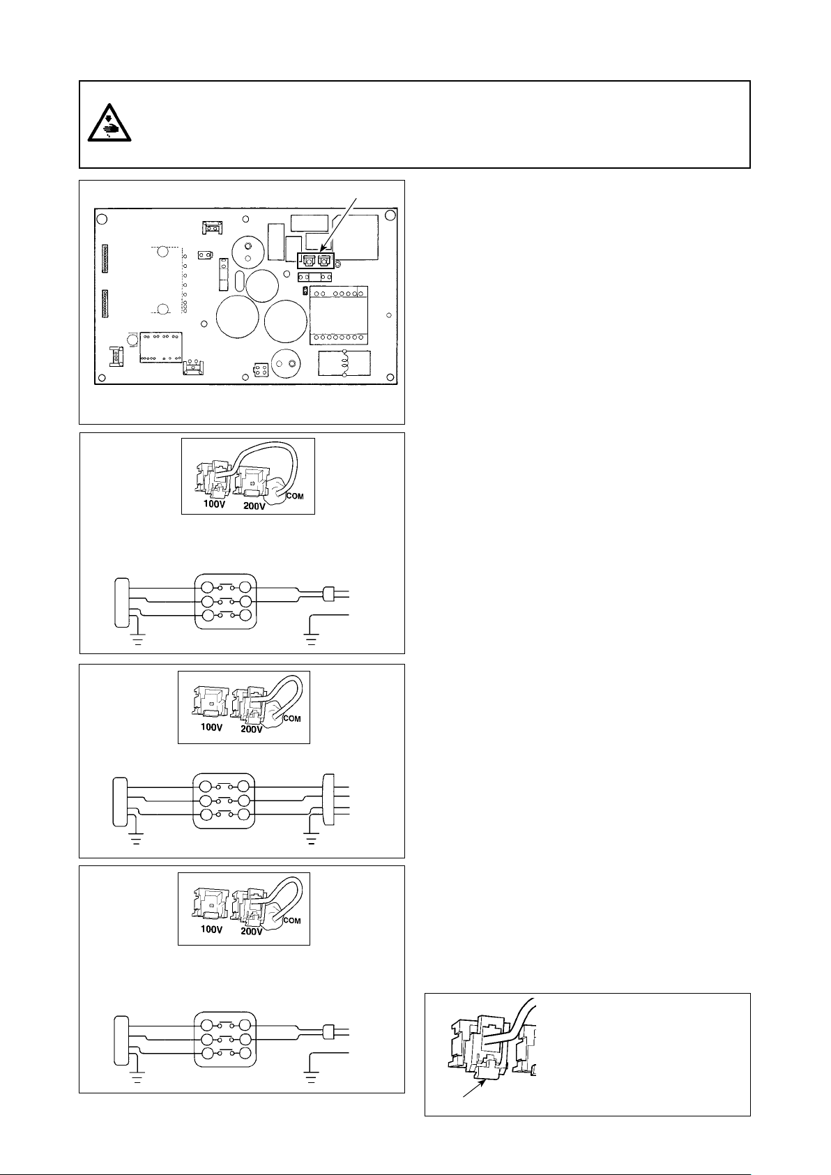
1. Changing over the voltage between 100 V and 200 V
WARNING :
To prevent personal injuries caused by electric shock hazards or abrupt start of the sewing machine,
carry out the work after turning OFF the power switch and a lapse of 5 minutes or more. To prevent
accidents caused by unaccustomed work or electric shock, request the electric expert or engineer of
our dealers when adjusting the electrical components.
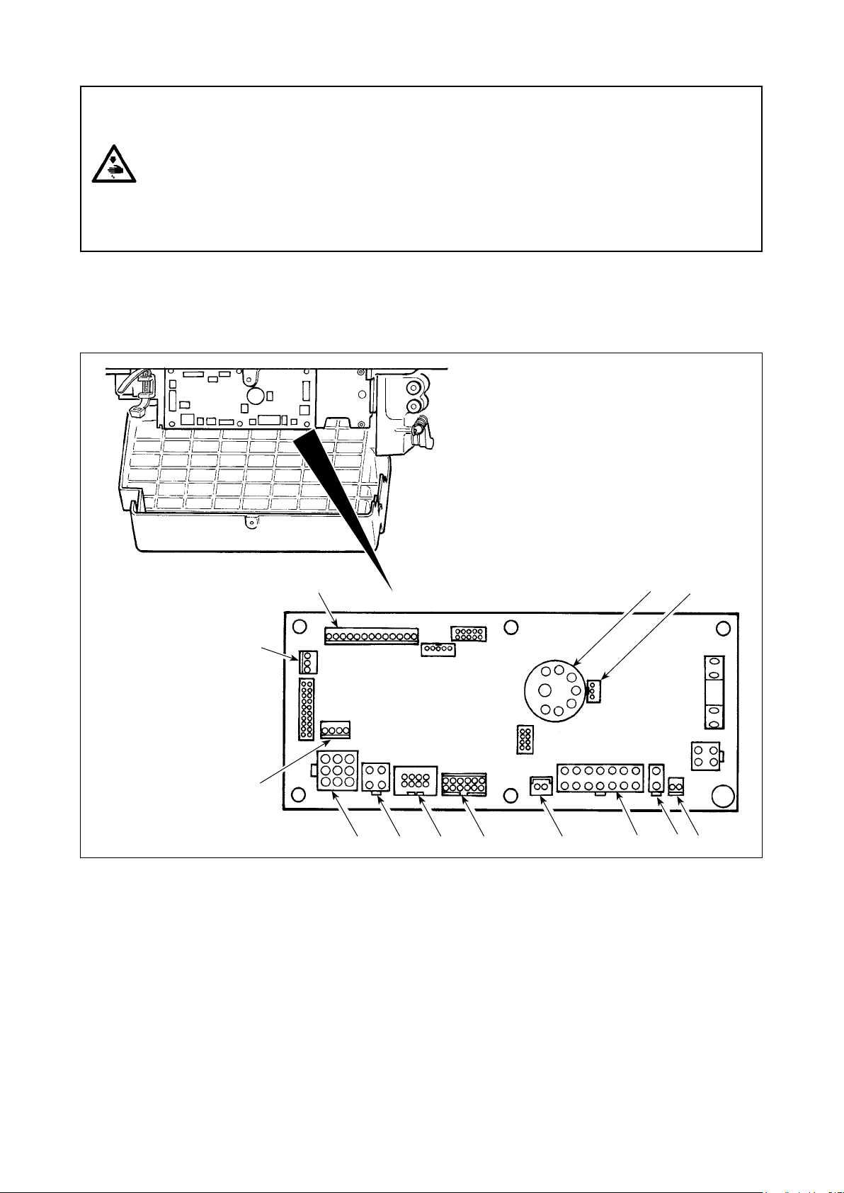
* The illustration below shows the PWR-T PCB.
The type of PCB differs by destination.
A
Wiring for the single-phase 100 V
(Box side)
Be sure to connect the wire between 1 and 2.
If it is connected between 1-3 or 2-3, the sewing
machine will be inoperative.
WHITE
BLACK
RED
GREEN/
YELLOW
1
2
3
YELLOW
WHITE
BLACK
GREEN/
(Plug side)
B
Wiring for the 3-phase 200 V
(Box side)
WHITE
BLACK
RED
GREEN/
YELLOW
1
2
3
YELLOW
(Plug side)
WHITE
BLACK
RED
GREEN/
C
Wiring for the single-phase 200 V
(Box side)
Be sure to connect the wire between 1 and 2.
If it is connected between 1-3 or 2-3, the sewing
machine will be inoperative.
WHITE
BLACK
RED
GREEN/
YELLOW
1
WHITE
BLACK
2
3
YELLOW
(Plug side)
GREEN/
❶
Depending on specications of the control box, the
number of phases and the voltage of the power supply
can be changed over among "single-phase 100 - 120 V,"
"single-phase 200 - 240 V" and "3-phase 200 - 240 V."
Replacement of the power cords
①
Changing-round of connector ❶ on the PWR PCB
②
1) Turn OFF the power with the power switch after
checking that the sewing machine has stopped.
2)
Draw out the power cord from the power receptacle
after checking that the power switch has been turned
OFF. Then wait for 5 minutes or more.
3) Loosen the screws which x the cover of the control
box. Open the cover in a slow manner.
4) Changing procedure of the power voltage
(Caution) If the supply power changing is carried out
in a wrong manner, the control box can
break. Be extremely careful when taking the
supply voltage changing procedure.
A. To change over the supply voltage from 200 -
240 V to 100 - 120 V
• Change the power cord with the JUKI genuine
cord with the part number (M90355800A0).
Change the earth cord with the one with the part
number (M90345800A0).
• Change over supply voltage changeover connector
mounted on the PWR PCB with the
❶
connector for 100 V.
• Connect the crimp style terminal of AC input cord
to the power plug as shown in the gure A.
B,C. To change over the supply voltage from 100 -
120 V to 200 - 240 V
• Change the power cord with the JUKI genuine
cord with the part number (M90175800A0).
• Change over supply voltage changeover connector
mounted on the PWR PCB with the
❶
connector for 200 V.
• Connect the crimp contact of the AC input cord
to the power plug as illustrated in Fig. B for the
3-phase power supply or as illustrated in Fig. C
for the single-phase one.
5) Before closing the door, check to be sure again that
the voltage has been changed without mistake.
6) Close the back lid and secure with the screws
pressing the lid, while taking extra care to prevent
the cord from being caught between the cover and
the main body of the control box.
(Caution)
Be sure to remove the connec-
tor while holding its locking
section with your ngers. Be
extremely careful not to pull
Locking section
the connector forcibly.
– 2 –
Page 5
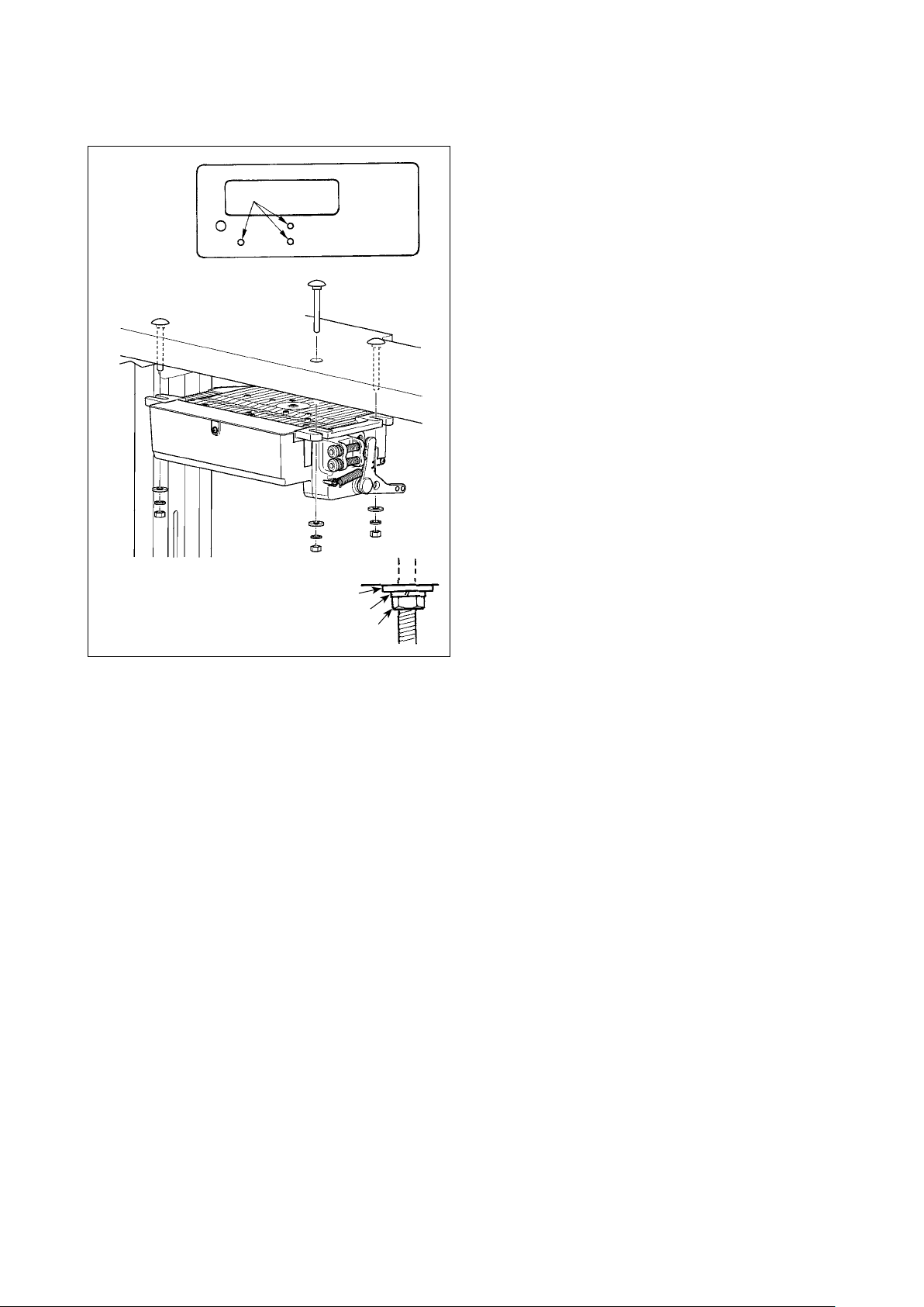
2. Installing to the table
In the case the SC-920 is used for the DD (direct-drive) type sewing machine head, install the control box on the
table following the instructions give below.
The description given below refers to the case the
SC-920 is installed on the table of the DDL-9000B. To
❶
use any other machine head, install the control box
on the table referring to the Instruction Manual for the
main body of the relevant sewing machine.
1) Install the control box to the table with the tting
bolt (asm.) ❶ supplied with the unit as acces-
sories. At this time, insert the nut and washer
supplied with the unit as accessories as shown
in the gure so that the control box is securely
xed.
2) After having installed the control box (and the
compact motor) on the table, mount the sewing
machine head on the table. (Refer to the Instruc-
tion Manual for the sewing machine to be used.)
Plain washer
Spring washer
Hexagonal nut
– 3 –
Page 6
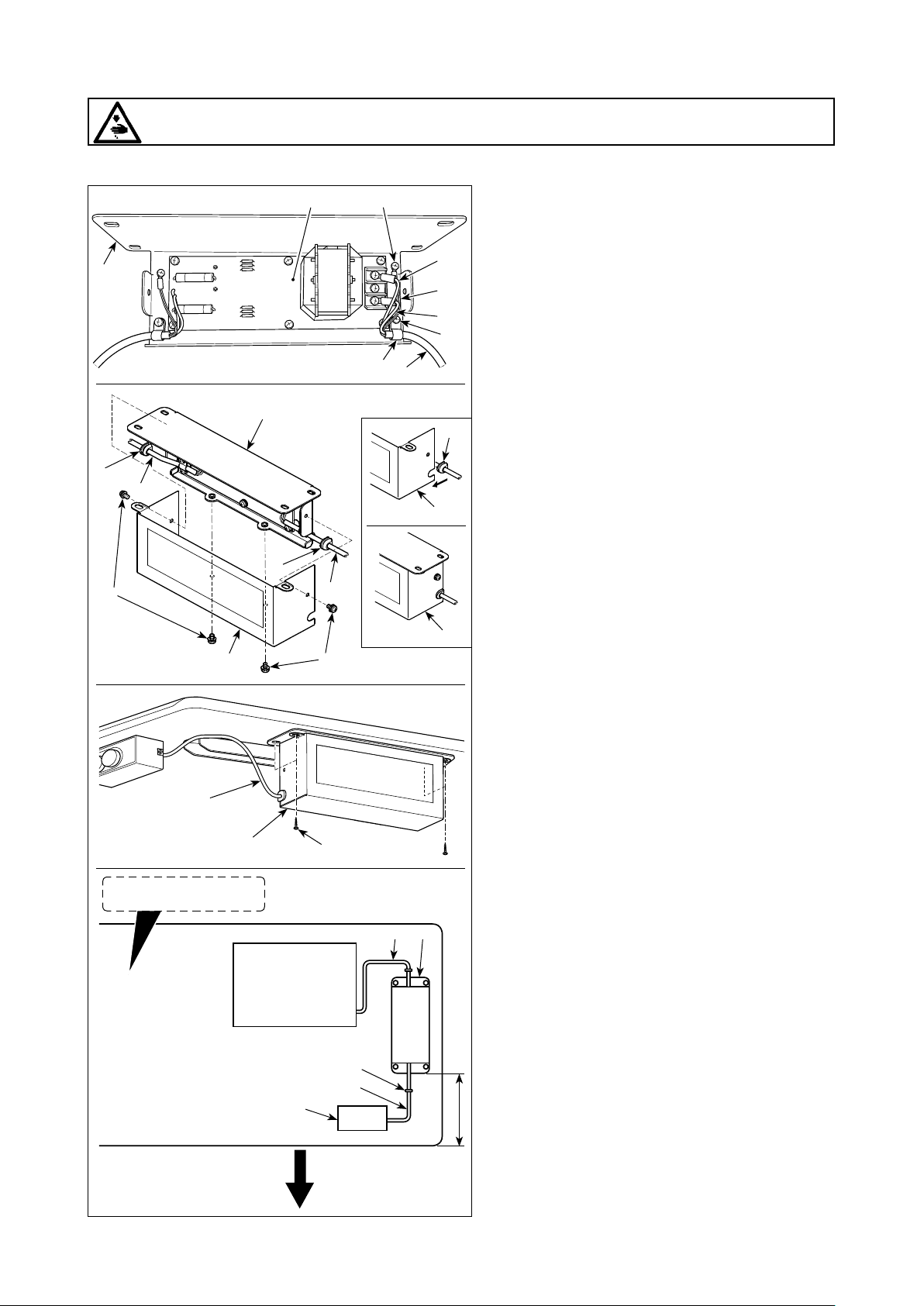
[How to install the reactor box]
WARNING :
Be sure to install the reactor box after turning the power OFF.
* For the EU-type models, install the reactor box that is supplied with the sewing machine.
❸
❽
❼
❾
❼
Undersurface of table
❸
❽
SC-920
❷ ❹
❺
❶
❾
❶
❶
A
C
B
❻
❽
1) Connect the terminals of power cord ❶ of the
SC-920 to reactor-box PCB asm. ❷ and to
reactor box mounting plate ❸.
Connect brown wire A to the rst connector
and blue wire B to the third connector respec-
tively from the top of terminal block on the
reactor box PCB asm. using screws. Connect
green/yellow wire C to reactor box mounting
plate ❸ with earth setscrew ❹.
2) Attach cable clip ❺ to the power cord of SC-
920. Attach the power cord together with the
cable clip to reactor box mounting plate ❸
with cable clip setscrew ❻.
3) Attach cord bushes ❽ to input/output cables
and ❼ of the reactor box.
❶
4) Attach reactor box cover to reactor box
mounting plate ❸ with four reactor-box cover
setscrews ❾.
At this time, x cord bushes ❽ attached to
input/output cables ❶ and ❼ in the concave
section on reactor box cover to eliminate a
gap between reactor box and cover .
5) Install reactor box on the table stand with
four accessory wood screws at the posi-
tion that is approximately 200 mm away from
the front end of table stand.
Adjust the installing position according to
the size of table stand so that the reactor
box does not protrude from the edge of table
stand.
6) Fix input/output cables ❶ and ❼ of reactor
box on the table stand using accessory
cord staple .
At this time, take care not to cross the input-
and output-cables.
Power box
Operator’s side
❼
200 mm
– 4 –
Page 7

3. Installing the control panel
WARNING :
To protect against possible personal injury due to abrupt start of the machine, be sure to start the
following work after turning the power off and a lapse of 5 minutes or more.
❶
❹
❸
❺
❷
1) Remove side plate setscrews ❶ from the side
plate.
2) Install control panel ❷ on the machine head using
screws ❺, at washers ❸ and rubber seat ❹ sup-
plied with the control panel as the accessories.
(Caution) 1. DDL-9000B (Not provided with AK) is
given as an example of installing proce-
dure.
2. Screw to install the panel changes
according to the machine head used.
Refer to Table 1 and conrm the kind of
screw.
< The relation between the respective machine heads and the positions of installing hole of the bracket are
as described in the table. >
Table 1
① ② ⑤ ⑥③ ④
Installing
hole
(Provided with AK)
DDL-9000B
LH-3500A
DLN-9010
DDL-8700 series
DDL-5500 series
LZ-2280 series
*1
For the DDL-5556 and LZ-228*, the machine head is supplied with an auxiliary
bracket for mounting the control panel as an accessory. Be sure to install the
bracket while referring to the instruction manual for the machine head.
①
②
②
③
*1
③
*1
③
M5 X 14
-
⑤
(Not provided with AK)
M5 X 12
- ⑤M5 X 14 Side plate setscrew
- ⑤3/16-28 L=12
- ⑤3/16-28 L=12
- ⑤3/16-28 L=12
- ⑤11/64-40 L=7.8
Screw
Side plate setscrew
Screw supplied with
panel as accessories
Screw supplied with
panel as accessories
Screw supplied with
panel as accessories
Screws supplied with
machine head
(Caution) 1. Screws to be used for installing the panel differ with the machine head, i.e., screws supplied with
the panel as accessories and the side plate setscrews. Select appropriate screws/setscrews referring to Table 1.
2. If the screw type is not correct, the tapped hole can be collapsed.
3. If you want to install the panel on the DDL-8700, be aware that the method to install it on the machine head differs depending on whether or not the machine head is provided with the AK device.
Machine head with the AK device:
Install the panel on the head bracket supplied with the AK. (The auxiliary bracket should be
xed with the side plate setscrews.)
Machine head without the AK device:
Remove the side plate setscrews and install the panel on the side plate using the screws sup-
plied with panel as accessories.
4. If you want to use the panel with the machine head for heavy-weight materials, install it referring
to the "Supplementary Instructions" for the machine head.
– 5 –
Page 8
4. Connecting the cords
WARNING :
• To prevent personal injury caused by abrupt start of the sewing machine, carry out the work after
turning OFF the power switch and a lapse of 5 minutes or more.
• Topreventdamageofdevicecausedbymaloperationandwrongspecications,besureto
connectallthecorrespondingconnectorstothespeciedplaces.(Ifanyoftheconnectorsis
inserted into a wrong connector, not only the device corresponding to the connector can break
but also it can start abruptly, inviting the risk of personal injury.)
• To prevent personal injury caused by maloperation, be sure to lock the connector with lock.
• As for the details of handling respective devices, read carefully the Instruction Manuals supplied
with the devices before handling the devices.
The SC-920 is provided with the connectors listed below. Connect the sewing-machine connectors to the corresponding control-box connectors according to the devices installed on the sewing machine.
(Caution) FortheSC-920Series,themachineheadtobeusedwithistobeselectedinthecourseof
the function setting procedure. To prevent an insertion error, remove the resistor pack for
the machine head selection before use.
❻
CN30 Motor signal connector
❶
CN38 Operation panel: Various kinds of sewing
❷
can be programmed. (For details of the
operation panel other than CP-18, refer to
the Instruction Manual for the panel to be
used.)
CN33 Synchronizer : It detects the needle bar
❸
position.
CN37 Presser foot lifting solenoid (Only for the
❹
automatic presser foot lifter type)
CN48 Safety switch (standard) : When tilting the
❺
sewing machine without turning the power
OFF, the operation of the sewing machine
is prohibited so as to protect against danger.
❸
❽
❹❾❼❷❺❶
CN42 Thread trimming safety switch
❻
CN39 Standing machine pedal : JUKI standard
❼
PK70, etc. Sewing machine can be controlled with external signals.
CN58 +24 V external power source
❽
CN57 Simplied production control counter input
❾
CN36 Machine head solenoid: Provided with so-
lenoids for thread trimming, reverse feed
stitching, one-touch type reverse feed
switch.
CN54 Material end detection sensor, etc.
CN50 Optional function/device input/output.
CN34 Pedal sensor: The pedal sensor supplied
with the SC-920 is to be connected to this
connector to operate the sewing machine.
– 6 –
Page 9
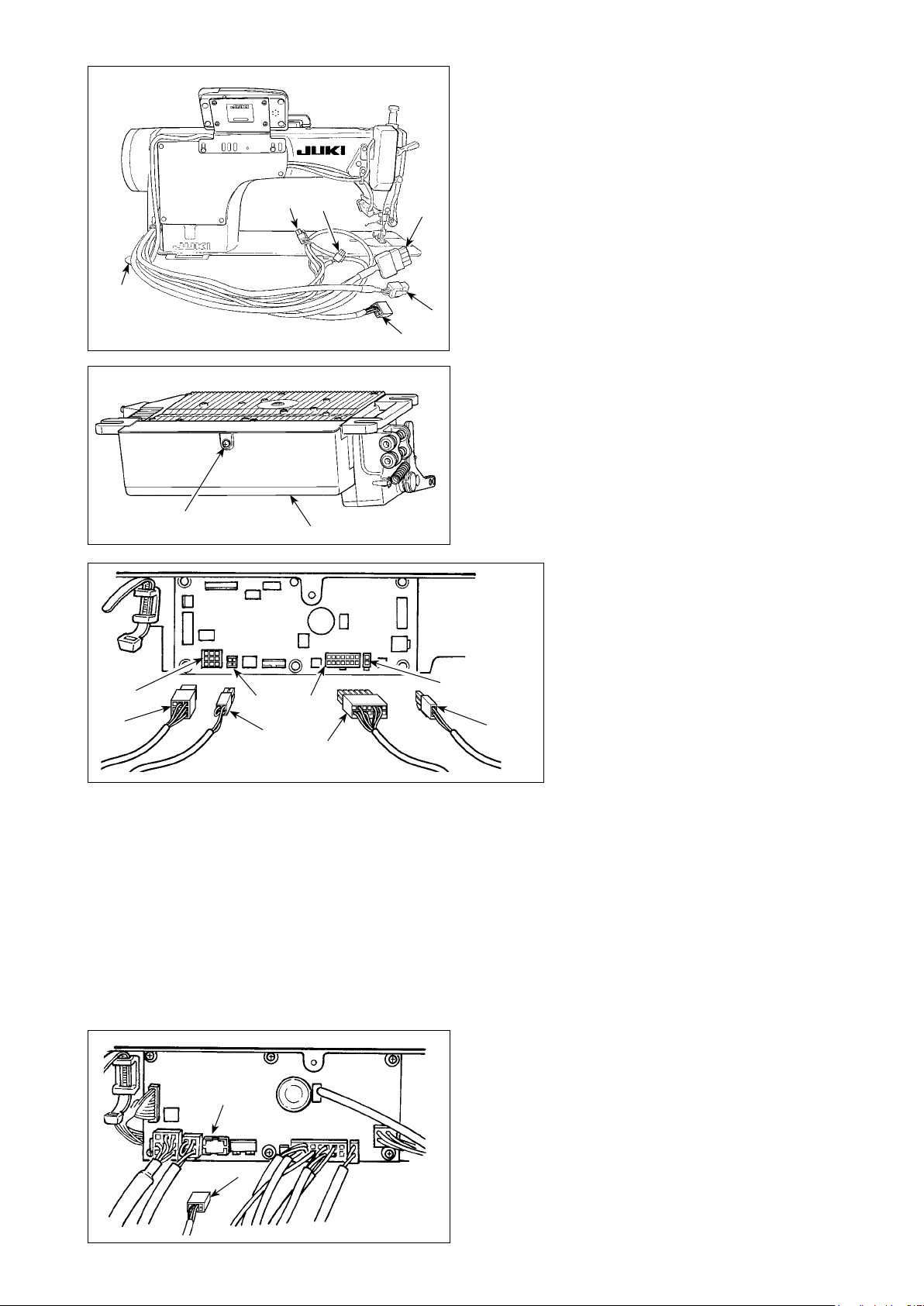
A
❶
❶
1) Pass cords ❶ of the thread trimming solenoid,
reverse-stitching solenoid, etc. and the cord from
the motor through hole A in the table to route them
down under the machine table.
❶
❶
❶
2) Loosen screw B in cover ❷ with a screwdriver to
open the cover.
B
❷
3) Connect 14P code ❸ coming from
the machine head to connector ❻
(CN36).
4) When the optional AK device is
attached, connect 2P connector ❹
coming from the AK device to con-
nector ❼ (CN37).
5) Connect connector ❺ coming from
the motor to connector ❽ (CN30) on
❺
❽
❾
❼
❻
❹
❸
the circuit board.
6) Insert 4P cord ❾ coming from the ma-
chine head into connector (CN48).
(Caution) 1. When using the AK device, set whether to use the AK device after conrming how to select
the auto-lifter function. (Refer to “III-11. Setting of the auto lifter function” p.40.)
2. Be sure to securely insert the respective connectors after checking the inserting directions
since all connectors have the inserting directions. (When using a type with lock, insert the
connectors until they go to the lock.) The sewing machine is not actuated unless the con-
nectors are inserted properly. In addition, not only the problem of error warning or the like
occurs, but also the sewing machine and the control box are damaged.
[Connecting the connector for the operation panel]
– 7 –
The SC-920 is provided with a connector for the op-
eration panel. Fully insert connector into connector
(CN38) on the PWB until it locks without fail while
carefully checking the orientation of connector .
(Caution) Be sure to turn OFF the power before
connecting the connector.
Page 10
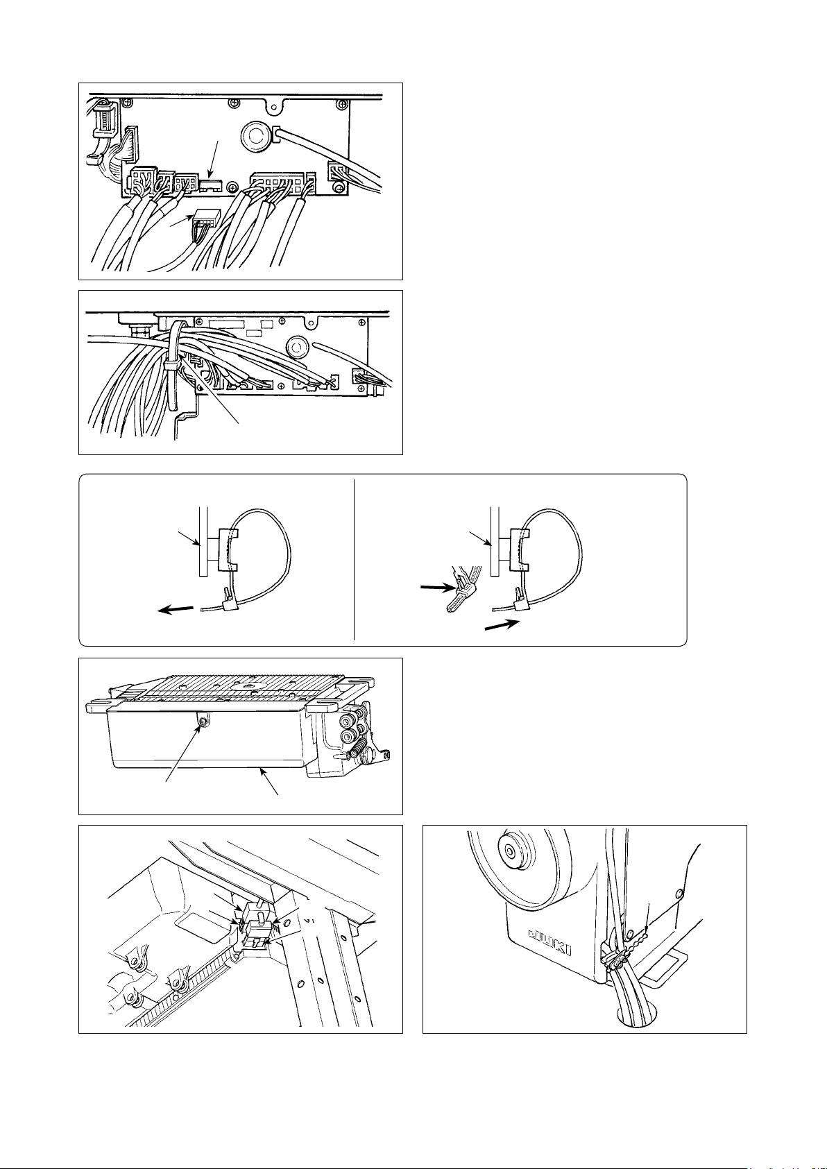
[ Connection of the pedal of standing-work machine ]
Connect the connector of PK70 to connector
(CN39 : 12P) of SC-920.
How to x cable clip band
Panel
(Caution) Be sure to turn OFF the power before
connecting the connector.
7) After inserting the connector, put all cords together
with cable clip band located on the side of the
box.
(Caution) 1. Fix the cord clamp and the cable clip
band following the attaching procedure.
2. When removing the connector,
remove it from the wire saddle and
remove it while pressing the hook of
the cable clip band.
How to remove cable clip band
Panel
Push the
hook.
Pushing
the hook
portion, push
the band to
remove it.
Pull
B
❷
Push
8) Close cover ❷ and x the cover by tightening screw
with a screwdriver.
B
(Caution) Take care not to allow the cord to be
caught under cover ❷.
9) Connect connector 4P to connector locat
on the side of the box.
10) Connect motor
outpu
t cord of the power switch to
connector .
ed
11) Bundle the machine head cables with a cable clip
supplied with the operation panel at one location
as shown in the gure.
– 8 –
Page 11
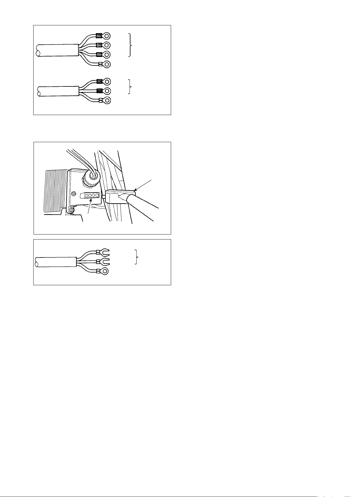
3ø 200V-240V
1ø 100V-120V
220V-240V
Black
Red
White
Green / Yellow
(ground wire)
Black
White
Green / Yellow
(ground wire)
[For CE specications only]
AC 200V-240V
AC 100V-120V
AC 220V-240V
12) Connect the power supply cord to the power plug
socket. Connect, as shown in the gure, the white
and black (and red) conductors or the brown and
blue conductors to the power supply side and the
green/yellow conductor to the grounding side.
(Caution) 1. Be sure to prepare the power plug
which conforms to the safety standard.
2. Be sure to connect the earth cable
(green/yellow) properly.
Connect motor output cord to connector locat-
ed on the side of the box.
CE 1ø 230V
Brown
Blue
Green / Yellow
(ground wire)
AC
220V-240V
Installing power switch
Connect power supply cord to the power switch.
[CE specications]
Single phase 230V : Power supply cords :
Brown, Blue
and green/yellow (ground wire)
(Caution) 1. Be sure to prepare the power plug
which conforms to the safety standard.
2. Be sure to connect the earth cable
(green/yellow) properly.
,
– 9 –
Page 12
[In case of using the power switch for LA]
Connect motor output cord to connector located
on the side of the box.
3ø 220V
1ø 120V
Black
Red
White
Green / Yellow
(ground wire)
Black
White
Green / Yellow
(ground wire)
AC
200V-240V
AC
100V-120V
Installing power switch
Connect power supply cord to the power switch.
[LA specications]
3-phase 220 V : Power supply cords : black, white,
red and green/yellow (ground wire)
Single phase 120V : Power supply cords : black, white,
and green/yellow (ground wire)
(Caution) 1. Be sure to prepare the power plug
which conforms to the safety standard.
2. Be sure to connect the earth cable
(green/yellow) properly.
When the metallic conduit is used, be sure to change over the power cord section following the steps of procedure described below.
(Caution) Be sure to carry out this procedure before installing the control box on the machine table.
A
B
Place the control box with its frame side down on
①
the machine table as illustrated in the sketch.
Loosen screw B in underside cover A to open the
②
cover.
D
C
Remove two screws C to remove clamping plate D
④
from the main body of the control box.
– 10 –
Change over the cord shown in the circle following
③
the steps of procedure described below.
F
E
F
Remove connector E while holding its locking sec-
⑤
tion F with your ngers.
Page 13
G
Turn connector G to remove the cord locking sec-
⑥
tion.
I
D
D
H
Loosen nut H to remove the connector from clamp-
⑦
ing plate D.
J
I
J
Put locknut I on the power cord and draw out the
⑧
cord J
from inside clamping plate D.
B
D
A
J
I
K
Install clamping plate D back to the control box.
⑨
Pass power cord J through conduit K.
⑩
Fix conduit K with locknuts I with clamping plate
⑪
placed between the locknuts.
D
Close underside cover A and secure the cover with
⑫
screw B.
13) Make sure that the power switch is turned OFF and
insert power supply cord coming from the power
switch into the power plug socket.
(Caution) Top end of power supply cord varies
in accordance with destination or supply
voltage. Check again the supply voltage
and the voltage designated on the con-
trol box when installing the switch.
– 11 –
Page 14
5. Attaching the connecting rod
WARNING :
To protect against possible personal injury due to abrupt start of the machine, be sure to start the
following work after turning the power off and a lapse of 5 minutes or more.
❷
1) Fix connecting rod ❶ to installing hole B of pedal
lever ❷ with nut ❸.
2) Installing connecting rod ❶ to installing hole A will
lengthen the pedal depressing stroke, and the pedal
operation at a medium speed will be easier.
❹
❸
❺
B
❶
A
3) The pressure increases as you turn reverse de-
pressing regulator screw ❹ in, and decreases as
you turn the screw out.
(Caution) 1. If the screw is excessively loosened,
the spring will come off.
Loosen the screw to such an extent
that the top of the screw can be observed from the case.
2. Whenever you have adjusted the
screw, be sure to secure the screw by
tightening metal nut ❺ to prevent the
screw from loosening.
– 12 –
Page 15
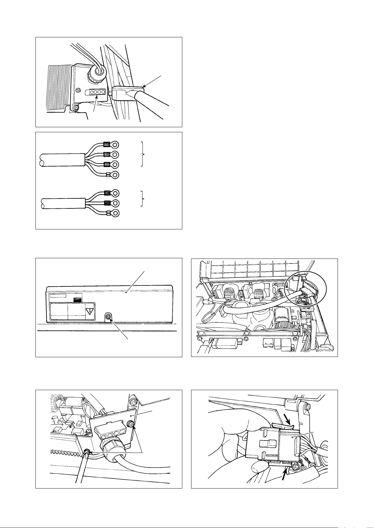
6. Setting procedure of the machine head
(Caution) For the operation panel other than CP-18, refer to the Instruction Manual for the operation
panel to be used for the setting procedure of the machine head.
1) Refer to
SC-920” p.24
“III-6. Setting of functions of
, and call the function
setting No. 95.
❺❹❸
❻
2) The type of machine head can be
selected by pressing switch ❺ (
switch ❻).
* Refer to the
"MACHINE HEAD LIST"
on the separate sheet or the Instruc-
tion Manual for the machine head of
your sewing machine for the type of
the machine head.
❺❹❸
❻
3) After selecting the type of machine
head, by pressing switch ❸ (
switch ❹), the step proceeds to
96 or 94, and the display automatically
changes to the contents of the setting
corresponding with the type of ma-
chine head.
❺❹❸
❻
– 13 –
Page 16
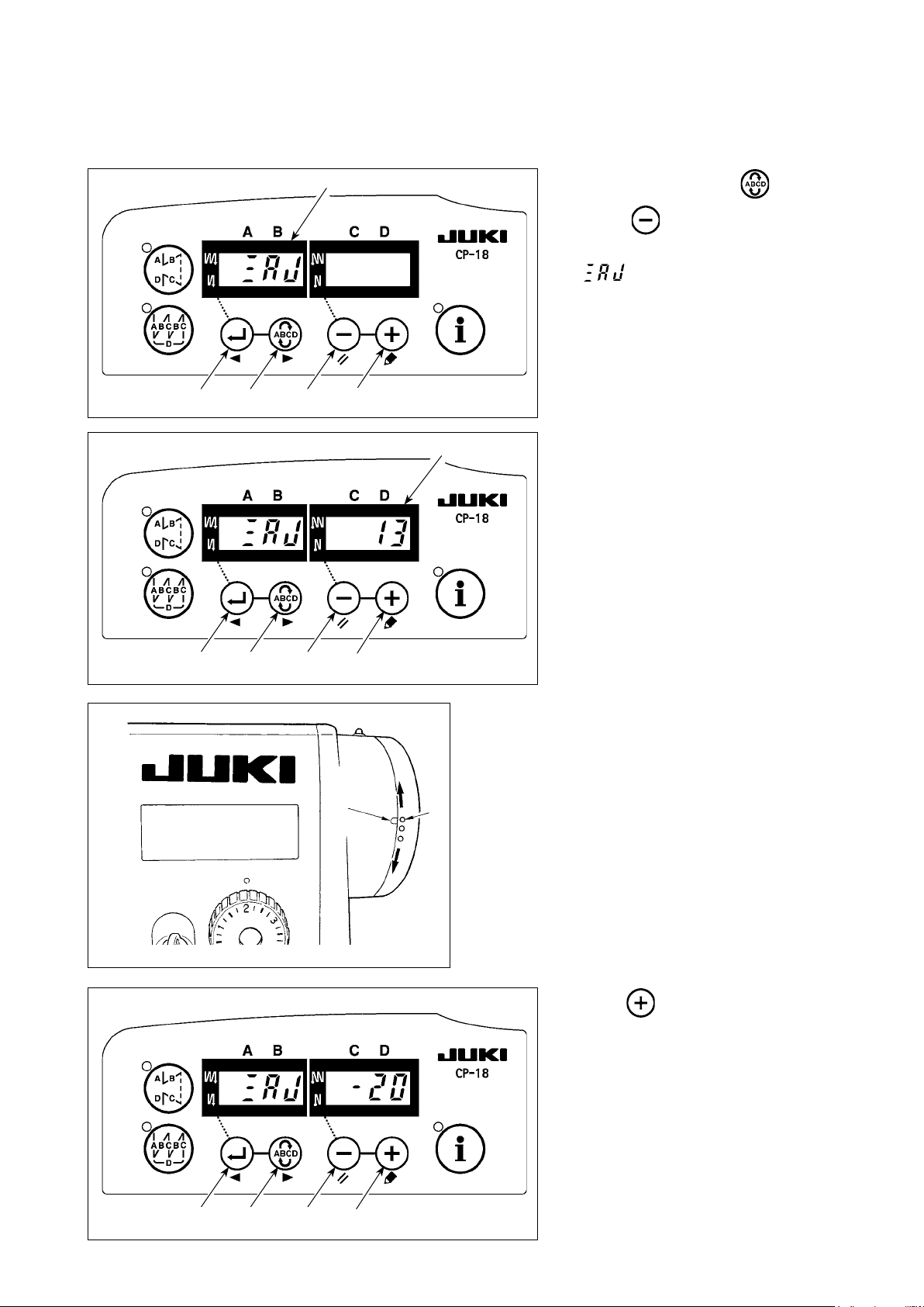
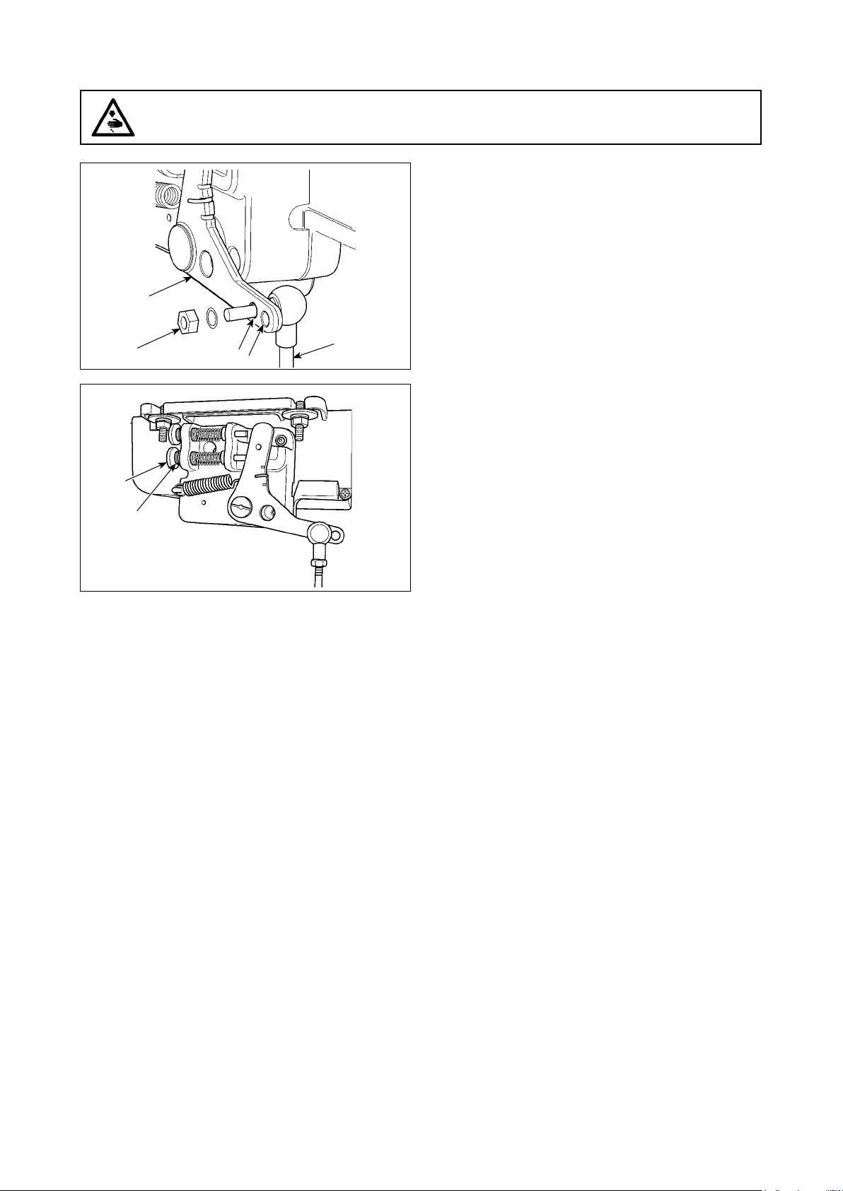
7. Adjusting the machine head (direct-drive motor type sewing machine only)
(Caution) When the slip between the white marker dot on the handwheel and the concave of the cov-
er is excessive after thread trimming, adjust the angle of the machine head by the opera-
tion below.
Ⓐ
1) Simultaneously pressing switch
and switch ❺, turn ON the
❹
power switch.
2) is displayed (Ⓐ) in the indica-
tor and the mode is changed over to
the adjustment mode.
❺❹❸
❻
Ⓑ
3) Turn the pulley of the machine head
by hand until the main-shaft reference
signal is detected. At this time, the de-
gree of an angle from the main-shaft
reference signal is displayed on the in-
dicator Ⓑ. (The value is the reference
value.)
❺❹❸
❻
4) In this state, align the white dot ❼ of the handwheel
with the concave ❽ of the pulley cover as shown in
the gure.
❽
❼
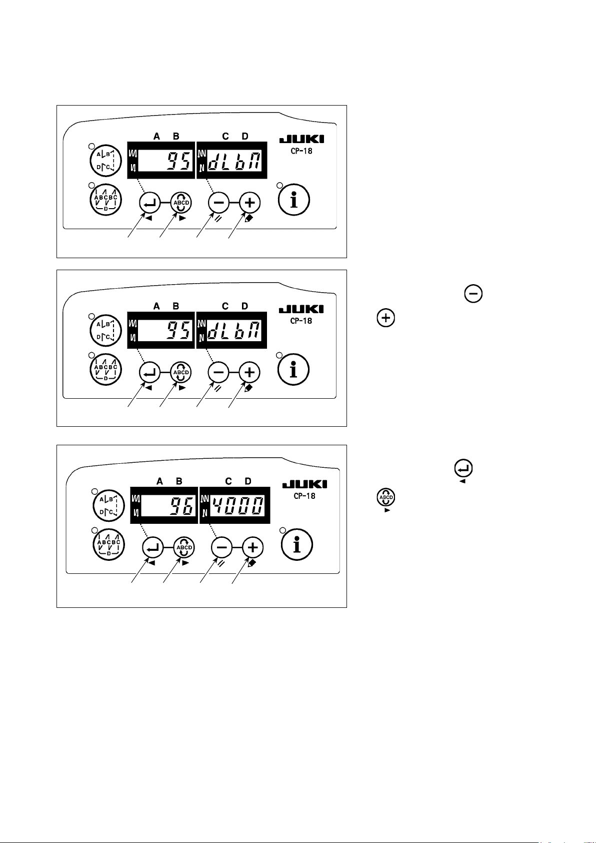
5) Press switch ❻ to nish the
adjustment work. (The value is the ref-
erence value.)
❺❹❸
❻
– 14 –
Page 17

III. FOR THE OPERATOR
1. Operating procedure of the sewing machine
1) Press ON button ❶ of the power switch to turn ON
the power.
(Caution) If the power indicator LED on the panel
does not light up after having turned ON
the power switch, immediately turn OFF
the power switch and check the supply
voltage. In addition, in such a case as
❶
2) When the needle bar is not in UP position, it auto-
matically turns to the UP position.
(Caution) When turning ON the power for the rst
3) The pedal is operated in the following four steps:
a. The machine runs at low sewing speed when you
❺
❹
❸
* When the auto-lifer (AK device) is used, one more operating switch is provided between the sewing ma-
chine stop switch and thread trimming switch. The presser foot goes up when you lightly depress the back
part of the pedal ❹, and if you further depress the back part ❺, the thread trimmer is actuated.
When starting sewing from the state that the presser foot has been lifted with the Auto-lifter and you de-
press the back part of the pedal, the presser foot only comes down.
• If you reset the pedal to its neutral position during the automatic reverse feed stitching at seam start, the
machine stops after it completes the reverse feed stitching.
• The machine will perform normal thread trimming even if you depress the back part of the pedal immediate-
ly following high or low speed sewing.
• The machine will completely perform thread trimming even if you reset the pedal to its neutral position im-
mediately after the machine started thread trimming action.
lightly depress the front part of the pedal.
b. The machine runs at high sewing speed when you
further depress the front part of the pedal. ❸
(If the automatic reverse feed stitching has been
preset, the machine runs at high speed after it com-
pletes reverse feed stitching.)
c. The machine stops (with its needle up or down)
when you reset the pedal to its original position.
d. The machine trims threads when you fully depress
the back part of the pedal.
this, re-turn ON the power switch when 2
to 3 minutes or more have passed after
turning OFF the power switch.
time, there is the case where the timing
is slightly retarded to perform the ini-
tialization work. When turning ON the
power, the needle bar moves. Do not put
your hands or things under the needle.
❸
❺
PFL KFL
Presser foot operation by pedal Enabled Disabled
Pedal depressing depth for thread trimming Deep Shallow
– 15 –
Page 18

❻
❼
4) For some types of the sewing machine heads, it is
possible to program various sewing patterns, using
the operation panel, such as the reverse feed stitch-
ing at sewing start and that at sewing end. Refer to
“III-3. Operating procedure of the sewing pat-
tern” p.18
for details when using CP-18 ❻. For
the operation panel other than CP-18 ❻, refer to
the Instruction Manual for the operation panel to be
used.
(The gure given illustrates the case of the DDL-
9000B.)
5) For some types of the sewing machine heads,
reverse feed is performed by pressing touch-back
switch ❼.
(The gure given illustrates the case of the DDL-
9000B.)
❷
6) When sewing is completed, press OFF button ❷ of
the power switch to turn OFF the power switch after
conrming that the sewing machine has stopped.
– 16 –
Page 19

2. Operation panel (CP-18)
❶
Ⓒ
Ⓓ
❸
switch : Used for changing over effective/ineffective of the reverse feed stitching pattern.
❶
switch : Used for changing over effective/ineffective of the overlapped stitching pattern.
❷
Ⓐ
❹ ❺ ❻❷
Ⓑ
Ⓔ
❼
switch : Used for conrming the contents of setting and for changing over effective/ineffective of the
❸
reverse feed stitching at sewing start.
switch : Used for selecting the process (A, B, C, D) the number of stitches for which is to be changed.
❹
* The selected process ashes on and off.
switch : Used for changing the content of the selected display (ashing section) and for changing over
❺
effective/ineffective of the reverse stitch at sewing end.
switch : Used for changing the content of the selected display (ashing section).
❻
switch : Used to call the production support function or one-touch setting (by keeping the switch held
❼
pressed for one second).
Indicators Ⓐ and Ⓑ : Various pieces of information are displayed.
LED Ⓒ : Lights up when the reverse feed stitching pattern is effective.
LED Ⓓ : Lights up when the overlapped stitching pattern is effective.
LED Ⓔ : Lights up when the production support function is displayed.
– 17 –
Page 20

3. Operating procedure of the sewing pattern
(Caution) For the operation panel other than CP-18, refer to the Instruction Manual for the operation
panel to be used.
(1) Reverse feed stitching pattern
Reverse feed stitching at sewing start and reverse feed stitching at sewing end can be separately programmed.
[Setting procedure of the reverse feed stitching]
1) Effective/ineffective of the reverse feed
stitching pattern can be changed over
by pressing switch ❶.
Ⓒ
❶
Ⓐ
Ⓑ
Ⓓ
When the reverse feed stitching
pattern is rendered effective, LED Ⓒ
lights up, the number of stitches of the
reverse feed stitching at sewing start
is displayed on Ⓐ, and the number of
stitches of the reverse feed stitching at
❷
❺❹❸
❻
❼
sewing end is displayed on indicator
.
Ⓑ
Select a process (A, B, C or D) the
number of stitches for which is to be
changed by using switch ❹.
The number which is ashing on and off represents the process which is being set.
Change the number of stitches for the selected process by using switch ❺ and switch ❻.
Press switch ❸ to conrm the
change you have made. (The number of stitches that can be set is 0 to
15.)
(Caution) The sewing machine cannot perform sewing when the display of the number of stitches for
a process is ashing on and off.
2) When the number of reverse feed
Ⓒ
❶
Ⓐ
Ⓑ
stitches display is not ashing on and
off, every press on switch ❸
changes over the reverse feed stitch-
Ⓓ
ing mode from the "reverse feed stitching at sewing start," "double reverse
feed stitching at sewing start" and "no
reverse feed stitching at sewing start."
❷
Without reverse
stitching :
Double reverse
stitching :
❺❹❸
❻
Reverse
stitching :
❼
In addition, every time switch ❺
is pressed, the reverse feed stitching
feature changes over from the reverse
feed stitching at sewing end to the
double reverse stitch at sewing end,
then to no reverse feed stitching at
sewing end, in turn.
(Caution) For some types of the ma-
chine head, reverse feed
stitching patterns are not
available.
– 18 –
Page 21

(2) Overlapped stitching pattern
Overlapped stitching pattern can be programmed.
A : Number of stitches of normal stitching setting
C
0 to 15 stitches
B : Number of stitches of reverse stitching setting
0 to 15 stitches
C : Number of stitches of normal stitching setting
0 to 15 stitches
D : Number of times of repetition
0 to 9 times
(Caution) When process D is set to 5 times, the sewing is repeat-
Ⓐ
Ⓒ
❶
A
B
C
B
D
ed as A → B → C → B → C.
[Setting procedure of the overlapped
Ⓑ
stitching]
1) Effective/ineffective of the overlapped
stitching pattern can be changed over
Ⓓ
by pressing switch ❷.
When the overlapped stitching pattern
is rendered effective, LED Ⓓ lights up.
2) Select a process (A, B, C or D) the
number of stitches for which is to be
❷
❺❹❸
❻
❼
changed by using switch ❹.
The number which is ashing on and
off represents the process which is be-
ing set.
3) Change the number of stitches for the selected process by using switch ❺ and switch ❻.
4) Press switch ❸ to conrm the change you have made.
(The sewing machine does not run unless the setting has been conrmed by pressing switch ❸.)
(Caution) The overlapped stitching pattern is carried out under automatic operation mode. Once the
pedal is depressed, the sewing machine will automatically perform sewing of the number of
overlapped stitches.
– 19 –
Page 22

4. One-touch setting
A part of function setting items can be easily changed in the normal sewing state.
(Caution) For the setting of functions other than those covered in this part, refer to
functions of SC-920” p.24
.
“III-6. Setting of
Ⓓ
Ⓒ
❷
❶
Ⓐ
❺❹❸
❻
Ⓔ
Ⓑ
❼
3) To return to the normal sewing state, press switch
(Caution) The setting is conrmed by pressing switch
Thread trimming function ( )
①
: Thread trimming operation is not performed (solenoid output prohibition: Thread trimmer, wiper)
: Thread trimming operation is effective.
Wiper function ( )
②
: Wiper does not operate after thread trimming : Wiper operates after thread trimming
❼
[One-touch setting procedure]
1) Keep switch
❼
one second to place the panel in the
function setting mode.
2) Change over the item to be set by
using switch
❸
or
Then, the set value can be changed
by using
switch
❺
switch ❻.
.
.
❼
held pressed for
switch
and
❹
.
One-shot automatic stitching function ( )
③
:
One-shot automatic stitching function is ineffective.
:
One-shot automatic stitching is effective.
(Caution) This function is rendered effective when the material end sensor function is set. It is not
possible to prohibit the one-shot operation during overlapped sewing operation. The number of revolution is the value which is set for setting No. 38.
Setting of the max. speed of stitch ( )
④
The highest speed of stitch of the machine head is set. The upper limit of the set value differs with the type
of machine head to which the SC is connected.
Setting range : 150 - Max. value [sti/min]
Material end sensor function ( )
⑤
: Material end sensor function is ineffective.
: Once the material end is detected, the sewing machine stops running after having sewn the num-
ber of stitches set with
* This function is rendered effective when the material edge sensor is set up.
Thread trimming function by material end sensor ( )
⑥
( ).
⑦
: Automatic thread trimming function after the detection of material end is ineffective.
: Once the material end is detected, the sewing machine performs thread trimming after having
sewn the number of stitches set with ⑦ ( ).
* This function is rendered effective when the material edge sensor is set up.
Number of stitches for material end sensor ( )
⑦
The number of stitches to be sewn from the detection of material end to the stop of the sewing machine
Number of stitches that can be set: 0 to 19 (stitches)
(Caution) If the number of stitches specied is inadequate, the sewing machine can fail to stop within
the preset number of stitches depending on the number of revolutions of the sewing machine.
– 20 –
Page 23

5. Production support function
The production support function consists of three different functions (six different modes) such as the production
volume management function, operation measuring function and bobbin counter function. Each of them has its
own production support effect. Select the appropriate function (mode) as required.
Production volume management function
■
Target No. of pcs. display mode [F100]
Target/actual No. of pcs difference display mode [F200]
The target number of pieces, actual number of pieces and the difference between the target and actual
number of pieces along with the operation time are displayed to notify the operators of a delay and advance
in real time. Sewing machine operators are allowed to engage sewing while constantly checking his/her
work pace. This helps raise target awareness, thereby increasing productivity. In addition, a delay in work
can be found at an early stage to enable early detection of problems and early implementation of corrective
measures.
Operation measuring function
■
Sewing machine availability rate display mode [F300]
Pitch time display mode [F400]
Average number of revolutions display mode [F500]
Sewing machine availability status is automatically measured and displayed on the control panel. The data
obtained can be used as basic data to perform process analyses, line arrangement and equipment efcien-
cy checkup.
Bobbin counter function
■
Bobbin counter display mode
In order to change bobbins before the current bobbin runs out of thread, the time for replacing the bobbin is
notied.
[To use the production support mode]
Ⓓ
Ⓒ
❷
❶
Ⓐ
❺❹❸
❻
Ⓑ
❼
(Caution) Modes F100 to F500 have been factory-set in the
OFF state at the time of delivery.
The mode state is changed over to ON/OFF
according to the setting of the bobbin thread
counter function (function setting No. 6).
Keep switch ❼ held pressed (one
second) in the normal sewing state to
call the one-touch setting screen.
Then, press switch ❶ or
switch ❷ to set each production support
mode in ON/OFF state to call the one-
touch setting screen.
Press switch ❸ or switch ❹ to
select the mode to be set in the ON/OFF
state.
ON/OFF of the display can be changed
over by pressing switch ❺ or
switch ❻.
To return to the normal sewing state,
press switch ❼.
– 21 –
Page 24

Sewing can be performed with the production support data displayed on the control panel.
[Basic operation of the production support modes]
1) When switch ❼ is pressed in
the normal sewing state, LED Ⓔ lights
Ⓒ
❶
Ⓐ
Ⓑ
up to enter the production support
mode.
Ⓓ
2) Production support function can be
changed over by pressing switch
or switch ❹.
❸
❷
❺❹❸
❻
Ⓔ
❼
3) Data attached marked with (*1) in Table 1 "Indicator Ⓐ" can be changed by means of switch ❺ and
switch ❻.
4) When you keep switch ❻ held pressed for two seconds, indicator Ⓑ and LED Ⓔ ash on and off.
While they are ashing on and off, data marked with (*2) in Table 1 "Display under modes" can be changed
by pressing switch ❺ and switch ❻.
When you press switch ❼, the value marked with (*2) is conrmed and indicator Ⓑ and LED Ⓔ stop
ashing on and off.
5) The value with a sharp mark (*3) in Table 1 "Display of modes" can be changed only immediately after re-
setting by using switch ❺ and switch ❻.
6) Refer to the table "Mode resetting operation," for the resetting procedure of data.
7) To return to the normal sewing state, press switch ❼.
Data to be displayed under the respective modes are as described in the table below.
Table 1: Display of modes
Mode name Indicator
Target No. of pcs. display
mode (F100)
Target/actual No. of pcs.
difference display mode
(F200)
Sewing machine availabili-
ty rate display mode (F300)
Pitch time display mode
(F400)
Average number of revolu-
tions display mode (F500)
Bobbin counter display
mode
Actual number of pieces
(Unit : piece)
Difference between target
number of pieces and
actual number of pieces
(d : piece) (*1)
oP-r Sewing machine availabili-
Pi-T Pitch time in the previous
ASPd Average number of rev-
bbn Bobbin counter value (*3) -
(*1)
Ⓐ
Indicator
Target number of pieces
(Unit : piece)
Target pitch time
(Unit : 100 msec) (*2)
ty rate in the previous sew-
ing (Unit : %)
sewing (Unit : 1sec)
olutions in the previous
sewing (Unit : sti/min)
Ⓑ
(*2)
Indicator Ⓑ (when
switch ❺ is pressed)
-
-
Display of average
availability rate of sewing
machine (Unit : %)
Display of average pitch
time (Unit : 100 msec)
Display of average num-
ber of revolutions
(Unit : sti/min)
– 22 –
Page 25

Table 2: Mode resetting operation
Mode name
Target No. of pcs. dis-
play mode (F100)
Target/actual No. of
pcs. difference display
mode (F200)
Sewing machine
availability rate display
mode (F300)
Pitch time display
mode (F400)
Average number of rev-
olutions display mode
(F500)
Bobbin counter display
mode
switch ❺ (held pressed for 2 seconds) switch ❺ (held pressed for 4 seconds)
Resets the actual number of pieces
Resets the difference between target num-
ber of pieces and actual number of pieces
Resets the actual number of pieces
Resets the difference between target num-
ber of pieces and actual number of pieces
Resets average availability rate of sewing
machine
Resets average pitch time Resets average availability rate of sewing
Resets average number of revolutions of
sewing machine.
Resets the bobbin counter value
(Note that only the bobbin counter is imme-
-
-
Resets average availability rate of sewing
machine.
Resets average pitch time.
Resets average number of revolutions of
sewing machine.
machine.
Resets average pitch time.
Resets average number of revolutions of
sewing machine.
Resets average availability rate of sewing
machine.
Resets average pitch time.
Resets average number of revolutions of
sewing machine.
-
diately reset by pressing switch ❺.)
[Detailed setting of production volume management function (F101, F102)]
When switch ❼ is held pressed
❶
(for three seconds) under the target No.
of pcs. display mode (F100) or the target/
actual No. of pcs. difference display
mode (F200), the detailed setting of the
production volume management function
can be carried out.
The setting state of the number of times
of thread trimming (F101) and that of the
❷
❺❹❸
❻
Ⓔ
❼
target achievement buzzer (F102) can be
changed over by pressing switch ❸
or switch ❹.
The number of times of thread trimming for sewing one piece of garment can be set by pressing switch ❺
or switch ❻ in the setting state of the number of times of thread trimming (F101).
It is possible to set whether the buzzer sounds or not when the actual number of pieces has reached the target
volume by pressing switch ❺ or switch ❻ in the setting state of the target achievement buzzer (F102).
– 23 –
Page 26

6. Setting of functions of SC-920
Functions can be selected and specied.
(Caution) For the function setting procedure of any operation panel other than CP-18, refer to the Instruction
Manual for the operation panel to be used.
1) Turn ON the power with switch
Ⓓ
Ⓓ
Ⓒ
Ⓒ
Ⓐ
❺❹❸
Ⓐ
❻
Ⓔ
❼
Ⓑ
Ⓑ
held pressed.
❼
(The item which has been changed
during the previous work is displayed.)
* If the screen display does not change,
re-carry out operation described in
step 1).
(Caution)
Be sure to re-turn ON the power
switch when one or more seconds
have passed after turning it OFF. If
the power switch is re-turned ON
immediately after turning it OFF, the
sewing machine may fail to operate
normally. In such a case, be sure
to turn ON the power switch again
properly.
2) To move the setting No. forward, press
Ⓓ
Ⓒ
switch ❹. To move the setting
No. backward, press switch ❸.
(Caution)
❺❹❸
Ⓐ
❻
Ⓔ
❼
Ⓑ
If the setting No. is moved forward
(or backward), the previous (or subsequent) content of the setting is
conrmed. Be careful when the content of a setting is changed (when
the
switch is touched).
/
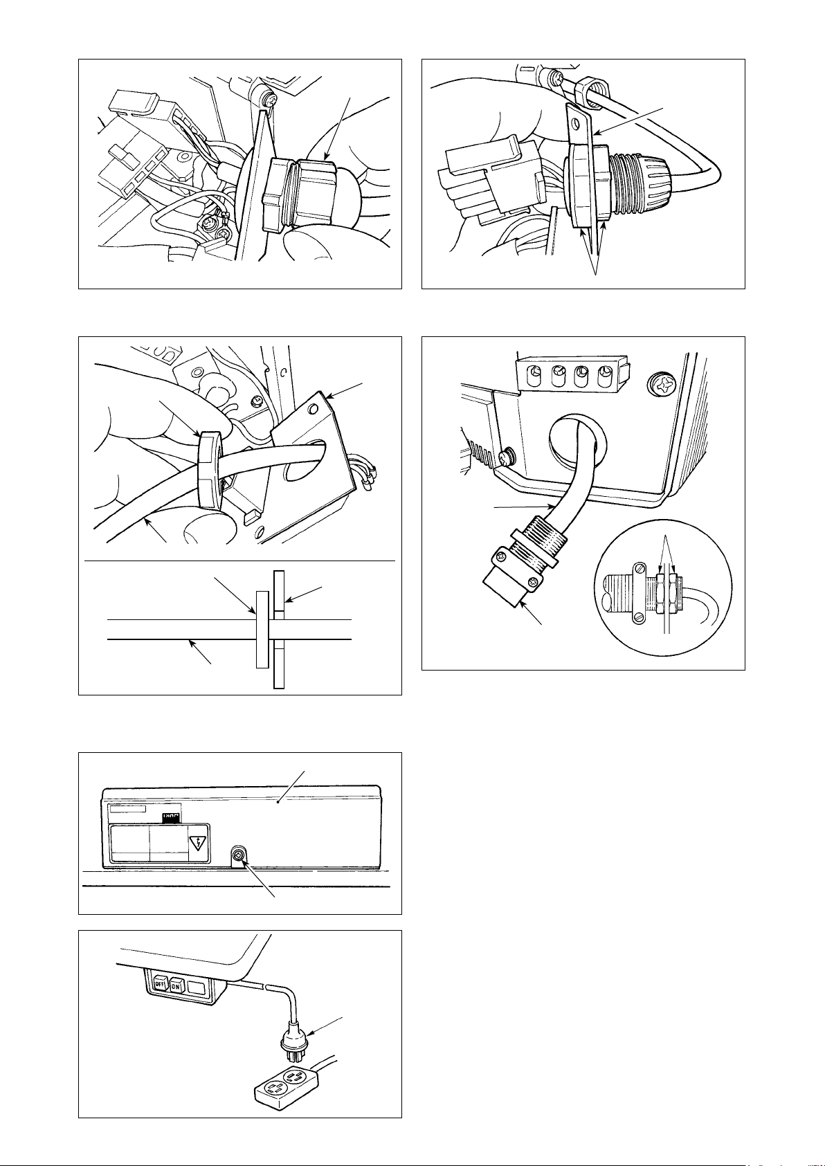
Example)
Changing the maximum number of revolu-
tions (setting No. 96)
Press switch ❸ or switch ❹
to call setting No. "96."
The current set value is displayed on
indicator Ⓑ.
❺❹❸
❻
Ⓔ
❼
Press switch ❺ to change the
setting to "2500."
* The content of setting of the setting No. returns to the initial value by pressing switch ❺ and switch ❻
simultaneously.
3)
After completion of the changing procedure, press switch ❸ or switch ❹ to conrm the updated value.
(Caution) If the power is turned OFF before carrying out this procedure, the changed content is not updated.
When switch ❸ is pressed, the display on the panel changes to the previous setting No. When
switch ❹ is pressed, the display on the panel changes to the subsequent setting No. After com-
pletion of the operation, the machine is returned to the normal sewing state by turning OFF the power
and re-turning it ON.
– 24 –
Page 27

7. Function setting list
No. Item Description
1 Soft start function The number of stitches to be sewn at a low speed when the
2 Material end
sensor function
3 Thread trimming
function by
material end
sensor
4 Number of
stitches for
material end
sensor
5 Flicker reducing
function
6 Bobbin thread
counting function
7 Unit of bobbin
thread counting
*
down
8 Number of
*
rotation of reverse
feed stitching
9 Thread trimming
prohibiting
function
10 Setting of needle
bar stop position
when the sewing
machine stops.
11 Operation
conrmation
sound for
operation panel
12 Optional switch
function selection
13 Function of
prohibiting start
of the sewing
machine by
bobbin thread
*
counter
14 Sewing counter Counting function of sewing (number of completion of process)
15 Thread wiping
function after
thread trimming
21 Function of
automatic presser
foot lifting at
pedal's neutral
position
22 Needle up/down
correction switch
changeover
function
* Do not change the set values with asterisk (*) mark as they are functions for maintenance. If the standard set value set at the
time of delivery is changed, it is in danger of causing the machine to be broken or the performance to be deteriorated. If it is
necessary to change the set value, please purchase the Engineer’s Manual and follow the instructions.
soft-start function is used at the start of sewing.
0 : The function is not selected.
1 to 9 : The number of stitches to be sewn under the soft-
start mode.
Material end sensor function (to be used only with CP-18).
0 : Material end detection function is not operative.
1 : After detecting material end, the specied number of
stitches (No. 4) will be sewn, and the sewing machine will
stop.
Thread trimming function by material end sensor (to be used
only with CP-18).
0 : Automatic thread trimming function after detection of
material end is not operative.
1 : After detecting material end, the specied number of
stitches (No. 4) will be sewn, and the sewing machine will
stop and perform automatic thread trimming.
Number of stitches for material end sensor (to be used only
with CP-18).
Number of stitches from detection of material end to stop of
the sewing machine.
Flicker reducing function
0 : Flicker reducing function is not operative.
1 : Flicker reducing function is effective
Bobbin thread counting function
0 : Bobbin thread counting function is not operative.
1 : Bobbin thread counting function is operative.
Unit of bobbin thread counting down
0 : 1 Count/10 stitches
1 : 1 Count/15 stitches
2 : 1 Count/20 stitches
3 : 1 Count/thread trimming
Sewing speed of reverse feed stitching 150 to
Thread trimming prohibiting function (to be used only with CP-
18).
0 : Thread trimming is effective.
1 : Thread trimming is prohibited.
(Output of solenoid is prohibited. : Thread trimmer and
wiper)
Position of needle bar is specied when the sewing machine
stops.
0 : The needle bar stops at its lower position.
1 : The needle bar stops at its upper position.
Operation conrmation sound for operation panel
0 : Operation conrmation sound is not generated
1 : Operation conrmation sound is generated.
Switching of function of optional switch.
Function of prohibiting start of the sewing machine by bobbin
thread counting
0 : When counting is out (-1 or less) Function of prohibiting
start of the sewing machine is not operative.
1 : When counting is out (-1 or less) Function of prohibiting
start of the sewing machine after thread trimming is oper-
ative.
2 : When counting is out (-1 or less), the sewing machine
stops once. Function of prohibiting start of the sewing
machine after thread trimming is operative.
0 : Sewing counter function is not operative.
1 : Sewing counter function is operative. (Every time thread
trimming is performed)
2 : With the sewing counting switch input function
Thread wiping operation after thread trimming is specied.
0 : Thread wiping is not carried out after thread trimming
1 : Thread wiping is carried out after thread trimming
Function of lifting presser foot when the pedal is in neutral
position.
0 : Function of neutral automatic presser lifting is not opera-
tive.
1 : Selection of function of neutral presser lifting.
Function of the needle up/down correction switch is changed
over.
0 : Needle up/down compensation
1 : One stitch compensation
Setting
range
0 to 9
(stitches)
0/1
0/1
0 to 19
(stitches)
0/1
0/1
0 to 3
3,000
(sti/min)
0/1
0/1
0/1
0 to 2
0 to 2
0/1
0/1
0/1
Indication of function setting
1
2
3
4
5
6
7
8 1 9 0 0
9
1 0
1 1
1 2 o P T _
1 3
1 4
1 5
2 1
2 2
0
0
0
5
0
1
0
0
0
1
0
1
1
0
0
Ref.
page
29
29
29
29
29
29
29
29
29
30
33
33
33
– 25 –
Page 28

No. Item Description
25 Thread trimming
operation after
turning the
handwheel by
han
29 Setting of one-
touch type
reverse feed
solenoid pull-in
time
30 Function of
reverse feed
stitching on the
way
31 Number of
stitches of reverse
feed stitching on
the way
32 Effective condition
of reverse feed
stitching on the
way when the
sewing machine
is stopping.
33 Thread trimming
function by
reverse feed
stitching on the
way
35 Number of
*
rotation at a low
speed
36 Number of
*
rotation of thread
trimming
37 Number of
rotation of softstart
38 One-shot speed One-shot speed (The max. value depends on the number of
39 Pedal stroke
*
at the start of
rotation
40 Low speed
*
section of pedal
41 Starting position
*
of lifting presser
foot by pedal
42 Starting position
*
of lowering
presser foot
43 Pedal stroke 2 for
starting thread
*
trimming
44 Pedal stroke
for reaching the
*
maximum number
of rotation
45 Compensation of
*
neutral point of
the pedal
47 Auto-lifter
selecting function
48 Pedal stroke 1 for
*
starting thread
trimming
49 Lowering time of
presser foot
50 Pedal
specication
51 Compensation of
solenoid-on timing
of reverse feed
stitching at the
start of sewing
* Do not change the set values with asterisk (*) mark as they are functions for maintenance. If the standard set value set at the
time of delivery is changed, it is in danger of causing the machine to be broken or the performance to be deteriorated. If it is
necessary to change the set value, please purchase the Engineer’s Manual and follow the instructions.
Thread trimming operation after moving the needle away from
its upper or lower position by turning the handwheel by hand is
specied.
0 : Thread trimming operation is carried out after turning the
handwheel by hand
1 : Thread trimming operation is not carried out after turning
the handwheel by hand
This function sets the suction time of initial motion of back-tack
solenoid.
50 ms to 500 ms
Function of reverse feed stitching on the way
0 : Normal one-touch type reverse feed stitching function
1 : Function of reverse feed stitching on the way is opera-
tive.
Number of stitches of reverse feed stitching on the way.
Effective condition of reverse feed stitching on the way
0 : Function is not operative when the sewing machine
stops.
1 : Function is operative when the sewing machine stops.
Thread trimming function by reverse feed stitching on the way
0 : Automatic thread trimming function after completion of
reverse feed stitching on the way is not operative.
1 : Automatic thread trimming after completion of reverse
feed stitching on the way is performed.
Lowest speed by pedal
(The MAX value differs by machine head.)
Thread trimming speed
(The MAX value differs by machine head.)
Sewing speed at the start of sewing (soft-start)
(The MAX value differs by machine head.)
rotation of the sewing machine head.)
Position where the sewing machine starts rotating from pedal
neutral position (Pedal stroke)
Position where the sewing machine starts accelerating from
pedal neutral position (Pedal stroke)
Position where the cloth presser starts lifting from pedal neutral position (Pedal stroke)
Starting position of lowering presser foot
Stroke from the neutral position
Position 2 where the thread trimming starts from pedal neutral
position (When the function of lifting presser foot by pedal is
provided.) (Pedal stroke)
(Effective only when Item No. 50 is set at 1.)
Position where the sewing machine reaches its highest sewing
speed from pedal neutral position (Pedal stroke) 10 to 150
Compensation value of the pedal sensor
Limitation time of waiting for lifting solenoid type auto-lifter
device
Position where thread trimming starts from pedal neutral position (Standard pedal) (Pedal stroke)
(Effective only when Item No. 50 is set at 0.)
Sets the time required until the lowering of the presser foot is
completed after a depress on the pedal
Type of pedal sensor is selected.
0 : KFL
1 : PFL
Refer to
p.39
Compensation of starting the solenoid for reverse feed
stitching when reverse feed stitching at the start of sewing is
performed.
“III-10. Selection of the pedal specications”
.
Setting
range
0/1
50 to 500
(ms)
0/1
0 to 19
(stitches)
0/1
0/1
150 to MAX
(sti/min)
100 to MAX
(sti/min)
100 to MAX
(sti/min)
150 to MAX
(sti/min)
10 to 50
(0.1 mm)
10 to 100
(0.1 mm)
– 60 to –10
(0.1mm)
8 to 50
(0.1 mm)
– 60 to –10
(0.1 mm)
(0.1 mm)
–15 to 15
10 to 600
(second)
– 60 to – 10
(0.1 mm)
0 to 500
(10 ms)
0/1
– 36 to 36
(10°)
Indication of function setting
2 5
2 9
3 0
3 1
3 2
3 3
3 5
3 6
3 7
3 8 2 5 0 0
3 9
4 0
4 1
4 2
4 3
4 4
4 5
4 7
4 8
4 9
5 0
5 1
1
2 5 0
0
4
0
0
2 0 0
4 2 0
8 0 0
3 0
6 0
– 2 1
1 0
– 5 1
1 5 0
0
6 0
– 3 5
1 4 0
1
– 8
Ref.
page
33
34
34
34
34
29
34
35
37
35
– 26 –
Page 29

No. Item Description
52 Compensation of
solenoid-off timing
of reverse feed
stitching at the
start of sewing
53 Compensation
of solenoid-off
timing of reverse
feed stitching at
the end of sewing
55 Foot lift after
thread trimming
56 Reverse
revolution to lift
the needle after
thread trimming
58 Function
of holding
predetermined
upper/lower
position of the
needle bar
59 Function of Auto/
Manual change-
over of reverse
feed stitching
at the start of
sewing
60 Function of stop
immediately after
reverse feed
stitching at the
start of sewing
64 Change-
over speed of
condensation
stitch or EBT (end
back tack)
70 Function of soft-
down of presser
foot
71 Double reverse
feed stitching
function
72 Sewing machine
startup selecting
function
73 Retry function This function is used when needle cannot pierce materials .
74 With/without
*
thread trimmer for
MF
76 One-shot function One-shot operation up to the material end is specied. (to be
84 Initial motion
suction time of
*
presser foot lifting
solenoid
* Do not change the set values with asterisk (*) mark as they are functions for maintenance. If the standard set value set at the
time of delivery is changed, it is in danger of causing the machine to be broken or the performance to be deteriorated. If it is
necessary to change the set value, please purchase the Engineer’s Manual and follow the instructions.
Compensation of releasing the solenoid for reverse feed
stitching when reverse feed stitching at the start of sewing is
performed.
Compensation of releasing the solenoid for reverse feed
stitching when reverse feed stitching at the end of sewing is
performed.
Function of lifting presser foot at the time of (after) thread
trimming
0 : Not provided with the function of automatic lifting of
work-clamp after thread trimming
1 : Provided with the function of lifting presser foot automati-
cally after thread trimming
Function of reverse revolution to lift the needle at the time of
(after) thread trimming
0 : Not provided with the function of reverse revolution to lift
the needle after thread trimming
1 : Provided with the function of reverse revolution to lift the
needle after thread trimming
Function of holding predetermined upper/lower position of the
needle bar
0 : Not provided with the function of holding predetermined
upper/lower position of the needle bar
1 : Provided with the function of holding predetermined
upper/lower position of the needle bar (holding force is
weak.)
2 : Provided with the function of holding predetermined
upper/lower position of the needle bar (holding force is
medium.)
3 : Provided with the function of holding predetermined
upper/lower position of the needle bar (holding force is
strong.)
This function can specify the sewing speed of reverse feed
stitching at the start of sewing.
0 : The speed will depend on the manual operation by ped-
al, etc.
1 : The speed will depend on the specied reverse feed
stitching speed (No. 8).
Function at the time of completion of reverse feed stitching at
the start of sewing
0 : Not provided with the function of temporary stop of the
sewing machine at the time of completion of reverse feed
stitching at the start of sewing
1 : Provided with the function of temporary stop of the
sewing machine at the time of completion of reverse feed
stitching at the start of sewing.
Initial speed when starting condensation stitch or EBT
Presser foot is slowly lowered.
0 : Presser foot is rapidly lowered.
1 : Presser foot is slowly lowered.
Effective/ineffective of double reverse feed stitching is
changed over. (to be used only with CP-18)
0 : Ineffective
1 : Effective
Current limit at the startup of sewing machine is specied.
0 : Normal (Current limit is applied during startup)
1 : Rapid (Current limit is not applied during startup)
0 : Retry function is not provided.
1 - 10 : Retry function is provided.
1: Needle-bar returning force before operating the retry
function: 1 (small) - 10 (large)
With/without thread trimmer for MF is selected.
0 : Not provided with the tread trimmer
1 : Provided with the thread trimmer
used only with CP-18)
0 : One-shot operation is not performed.
1 : One-shot operation is performed.
Suction motion time of presser foot lifting solenoid
Setting
range
– 36 to 36
(10°)
– 36 to 36
(10°)
0/1
0/1
0 to 3
0/1
0/1
0 to 250
(sti/min)
0/1
0/1
0/1
0 to 10
0/1
0/1
50 to 500
(ms)
Indication of function setting
5 2
5 3
5 5
5 6
5 8
5 9
6 0
6 4
7 0
7 1
7 2
7 3
7 4
7 6
8 4
1 0
1 5
1
0
0
1
0
1 8 0
0
1
0
1
0
0
1 4 0
Ref.
page
35
35
36
36
36
36
36
37
37
29
37
– 27 –
Page 30

No. Item Description
87 Function of pedal
curve selection
90 Initial motion up
stop function
91 Function of
prohibiting
compensation
operation
after turning
handwheel by
hand
92 Function of
reducing speed
of reverse feed
stitching at the
start of sewing
93 Function added to
needle up/down
compensating
switch
94 Continuous +
One-shot nonstop
function
95 Head selection
function
96 Max. number of
rotation setting
100 Number of
stitches sewn
before thread
clamp works at
the beginning of
sewing
103 Needle cooler
output OFF delay
time
120 Main shaft
reference angle
compensation
121 Up position
starting angle
compensation
122 DOWN position
starting angle
compensation
124 Setting of energy-
saving function
during standby
* Do not change the set values with asterisk (*) mark as they are functions for maintenance. If the standard set value set at the
time of delivery is changed, it is in danger of causing the machine to be broken or the performance to be deteriorated. If it is
necessary to change the set value, please purchase the Engineer’s Manual and follow the instructions.
Pedal curve is selected. (Improving pedal inching operation)
Number of rotations
Automatic UP stop function is set immediately after turning ON
the power.
0 : off
1 : on
It is effective in combination with the machine head provided
with tension release function.
0 : Tension release function is ineffective.
1 : Tension release function is effective. 0/1
Function to reduce speed at the time of completion of reverse
feed stitching at the start of sewing.
0 : Speed is not reduced.
1 : Speed is reduced.
Operation of needle up/down compensating switch is changed
after turning ON the power or thread trimming.
0 : Normal (needle up/down compensating stitching only)
1 : One stitch compensating stitching is performed only
when aforementioned changeover is made. (Upper stop /
upper stop)
The function that does not stop the sewing machine by combining continuous stitching with one-shot stitching using the
program sewing function which is available in the IP operation
panel.
0 : Normal (The sewing machine stops when a step is com-
pleted.)
1 : The sewing machine does not stop when a step is com-
pleted and proceeds to next step.
Machine head to be used is selected.
(When the machine head is changed, each setting item is
changed to the initial value of the machine head.)
Max. number of rotation of the sewing machine head can be
set. (The MAX value differs by machine head.)
Sets the number of stitches to be sewn at the beginning of
sewing before the thread clamp solenoid (CN36-7) starts operating
0 : Thread clamp solenoid does not operate.
1 to 9 : The number of stitches to be sewn before the thread
clamp solenoid operates
Delay time from the stop of sewing machine to the output OFF
is specied using the needle cooler output function.
Main shaft reference angle is compensated.
Angle to detect UP position starting is compensated.
Angle to detect DOWN position starting is compensated.
Setting to reduce the power consumption while the sewing
machine is in standby state
0 : Energy-saving mode is ineffective
1 : Energy-saving mode is effective
2
0
1
Pedal stroke
Setting
range
0/1/2
0/1
0/1
0/1
0/1
150 to MAX
(sti/min)
0 to 9
(stitches)
100 to 2000
(ms)
–60 to 60
–15 to 15
–15 to 15
0/1
Indication of function setting
8 7
9 0
9 1
9 2
9 3
9 4
9 5 d L b M
9 6 4 0 0 0
1 0 0
1 0 3
1 2 0
1 2 1
1 2 2
1 2 4
5 0 0
– 2 3
Ref.
page
37
0
38
1
1
37
0
38
0
38
0
38
0
38
38
5
38
0
0
38
– 28 –
Page 31

8. Detailed explanation of selection of functions
Selection of the soft-start function (Function setting No. 1)
①
The needle thread may fail to interlace with the bobbin thread at the start of sewing when the stitching pitch (stitch
length) is small or a thick needle is used. To solve such problem, this function (called “soft-start”) is used to limit
the sewing speed, thereby assuring successful formation of the starting stitches.
0 : The function is not selected.
1 to 9 : The number of stitches to be sewn under the soft-start mode.
1 0
The sewing speed limited by the soft-start function can be changed.
Data setting range
3 7 08 0
100 to MAX sti/min <10 sti/min> (The MAX value differs by machine head.)
Material end sensor function (Function setting No. 2 to 4, 76)
②
This function is possible when the material end sensor is attached.
For details, refer to
material end sensor.
(Caution) This function is rendered effective only with the CP-18.
Flicker reducing function (Function setting No. 5)
③
The function reduces ickering of the hand lamp at the start of sewing.
0 : Flicker reducing function is ineffective
1 : Flicker reducing function is effective
(Caution) When the icker reducing function is set at the "Flicker reducing function is effective," the startup
Bobbin thread counting function (Function setting No. 6)
④
When the control panel is used, the function subtracts from the predetermined value and indicates the used
amount of bobbin thread.
For the details, refer to the instruction manual for the control panel.
0 : Bobbin thread counting function is not operative.
1 : Bobbin thread counting function is operative.
(Caution) If “0” is set, the LCD indication on the control panel will go out and the bobbin thread counting
5 0
speed of the sewing machine decreases.
6 1
“III-15. Connection of the material end sensor” p.43
function will be invalid.
(Function setting No. 37)
and the Instruction Manual for the
Thread trimming prohibiting function (Function setting No. 9)
⑤
This function turns OFF thread trimming solenoid output and wiper solenoid output when thread trimming is
actuated.
(Caution) This function is rendered effective only with the CP-18.
By this function, separate sewing material can be spliced and sewn without trimming thread.
0 : off Thread trimming is operative. (thread can be trimmed).
1 : on Thread trimming is inoperative. (thread can not be trimmed).
Setting of the needle bar stop position when the sewing machine stops (Function setting No. 10)
⑥
The position of the needle bar when the pedal is in its neutral position is specied.
0 : Down The needle bar stops in the lowest position of its stroke.
1 : Up The needle bar stops in the highest position of its stroke.
(Caution) If the stop position of the needle bar is set to the highest position, the thread trimming action will
Panel operating sound (Function setting No. 11)
⑦
Whether the panel operation generates sound or not can be selected.
0 : off Operation conrmation sound is not generated
1 : on Operation conrmation sound is generated.
9 0
1 0 0
be taken after the needle bar comes down once to the lowest position.
1 1 1
– 29 –
Page 32

Selection of the optional input/output function (Function setting No. 12)
⑧
❶
Ⓐ
Ⓑ
❷
1 2 TPo _
TPo _
0i 1 ** *
1i 2
0o 1 ** *
0o 3
nE_ d
_ni _
Tuo _
❺❹❸
Select function setting No. 12 with the operating procedure of function setting
procedures 1) through 3).
Select the items of "End", "in" and "ouT" with keys ❺ and ❻.
[When "in" is selected]
The input function setting connector indication number is shown on indicating
section Ⓐ. Designate the indication number by means of key ❸ or ❹. Specify
the function of the pin of the connector corresponding to the indication number
by means of key ❺ or ❻.
Function code and abbreviation are displayed alternately on indicator Ⓑ.
(For the relation between signal input No. and connector pin array, refer to the
separate list.)
[When "ouT" is selected]
The output function setting connector indication number is shown on indicating
section Ⓐ. Designate the indication number by means of key ❸ or ❹. Specify
the function of the pin of the connector corresponding to the indication number
by means of key ❺ or ❻.
Function code and abbreviation are displayed alternately on indicator Ⓑ.
(Refer to the separate table for the relation between the signal output numbers
and the connector pin conguration.)
❻
❼
* Example) To assign the thread trimming function to the input function setting connector indication
number "i01" (CN36-4)
1 2 TPo _
TPo _
_ni _
0i 1 on P
0i 1 ST W
Lighting alternately
L 4
0i 1
L 4
H 4
0i 2 SFS W
TPo _
_ni _
1. Select function setting No. 12 with the operating procedure of function setting
procedures 1) through 3).
2. Select the item of "in" with keys ❺ and ❻.
3. Select the port of the indication number "i01" by means of key ❹.
4. Select the thread trimming function, "TSW" with keys ❺ and ❻.
5. Determine the thread trimming function, "TSW" with key ❹.
6. Set ACTIVE of the signal with keys ❺ and ❻.
Set the display to "L" when the signal is "Low" and performing thread trim-
ming, and set the display to "H" when the signal is "High" and performing
thread trimming.
7. Determine the aforementioned function with key ❹.
8. Finish the optional input with key ❹.
TPo _
nE_ d
9. Select the item of "End" with keys ❺ and ❻ to return to the function setting
mode.
– 30 –
Page 33

Input function list
Function
code
Abbrevia-
tion
0 noP No function (Standard setting)
1 HS Needle up / down compensat-
ing stitching
2 bHS Back compensating stitching Reverse feed stitching is performed at low speed while
3 EbT Function of canceling once re-
verse feed stitching at the end
of sewing
4 TSW Thread trimming function This function is actuated as the thread trimming
5 FL Presser foot lifting function This function is actuated as the foot lifter switch.
6 oHS One stitch compensating
stitching
7 SEbT Function of cancel of reverse
feed stitching at start/end
8 PnFL Presser lifting function when
pedal is neutral
9 Ed Material edge sensor input This function works as the input signal of material
10 LinH Function of prohibiting de-
pressing front part of pedal
11 TinH Function of prohibiting thread
trimming output
12 LSSW Low speed command input This function works as low speed switch for standing
13 HSSW High speed command input This function works as high speed switch for standing
14 USW Needle lifting function UP stop motion is performed when switch is pressed
15 bT Reverse feed stitching switch
input
16 SoFT Soft start switch input The speed of stitch is limited to the predetermined
17
18
19
20
21
22
23 Tiin Tsw command prohibition input Thread trimming command is prohibited.
24 USTP Lsw command prohibition/nee-
oSSW
bKoS
SFSW
MES
AUbT
CUnT
One-shot speed command
switch input
Backward one-shot speed
command switch input
Safety switch input Rotation is prohibited.
Thread trimming safety switch
input
Automatic reverse feed stitching cancellation/addition switch
Sewing counter input Every time the switch is pressed, the sewing counter
dle-up stop input
Function item Remarks
Every time the switch is pressed, normal feed stitching
by half stitch is performed. (Same operation as that of
up / down compensating stitching switch on the panel.)
the switch is held pressing. (It is effective only when a
constant-dimension sewing is selected.)
By depressing the back part of the pedal after press-
ing the switch, operation of reverse feed stitching is
canceled once.
switch.
Every time the switch is pressed, one stitch stitching
operation is executed.
By operating the optional switch, ineffective/effective
can be alternately changed over.
Every time the switch is pressed, the function whether
automatically lifting the presser foot when the pedal is
neutral or not can be selected.
edge sensor.
Rotation by pedal is prohibited.
Output of thread trimming is prohibited.
sewing machine.
sewing machine.
during DOWN stop.
Reverse feed stitching is output as long as the switch
is held pressed.
soft-start speed as long as the switch is held pressed.
This function works as one-shot speed command as
long as the switch is pressed.
Reverse feed stitching is performed in accordance with
the one-shot speed command as long as the switch is
held pressed.
It operates as an input signal of the thread trimmer
safety switch.
Every time the switch is pressed, reverse feed stitch-
ing at sewing start or reverse feed stitching at sewing
end is cancelled or added.
value is increased.
Sewing by means of the pedal switch is prohibited.
The sewing machine stops with its needle up during
sewing.
– 31 –
Page 34

Output function list
Function
code
10 CooL Needle cooler output Output for needle cooler
11 bUZ Buzzer output
12 LSWo Revolution command output Revolution demanding command state is output.
13 TSWo Tsw command monitor output Thread trimming command status is output.
Abbrevi-
ation
0 noP No function (Standard setting)
1 TrM Thread trimming output Output of thread trimming signal
2 WiP Thread wiper output Output of thread wiper signal
3 TL Thread release output Output of thread release signal
4 FL Presser lifter output Output of presser lifting signal
5 bT Reverse feed stitching output Output of reverse feed stitching signal
6 EbT EBT cancel monitor output State of one time cancel of reverse feed stitching at
7 SEbT Reverse feed stitching at start/
end cancel monitor output
8 AUbT Sewing start/end cancellation/
addition monitor output
9 SSTA
Sewing machine stop state
output
Function item Remarks
end function is output.
State of cancel of reverse feed stitching at start/end is
output.
State of cancel or addition of automatic reverse feed
stitching is output.
Sewing machine stop state is output.
It is output when the bobbin counter set value has been
exceeded, an error has occurred or the bobbin thread
remaining amount is detected.
Input function setting connectors
Connector No. Pin No. Display No. Initial value of function setting
CN36 4 i01 noP (No function setting)
CN48 2 i02 SFSW (Safety switch input)
CN50 12 i03 SoFT (Soft-start speed limit input)
CN36 5 i04 bT (Reverse feed stitching switch input)
CN50 11 i05
7 i06 TSW (Thread trimming switch input)
CN39
CN57 1 i10
CN42 2 i11 noP (No function setting)
CN54 3 i12 noP (No function setting)
Output function setting connector
Connector No. Pin No. Display No. Initial value of function setting
CN50
11 i07 LSSW (Low-speed revolution switch input)
9 i08
5 i09 FL (Presser foot lifting switch input)
7 o01 bT (Reverse feed stitching output)
8 o02 TrM (Thread trimming output)
9 o03 LSWo (Revolution request input)
LinH (Input of prohibition of depress on front part of
pedal)
HSSW (High-speed revolution switch input)
CUnT (Sewing counter input)
– 32 –
Page 35

Sewing counting function (Function setting No. 14)
⑨
The function counts up every time thread trimming is completed and counts the number of completion of the
sewing process.
0 : off Sewing counting function is inoperative.
1 4 1
1 : on Sewing counting function is operative. (Every time thread trimming is
performed)
2 : on External sewing counter switch input.
(Caution) The sewing counter can only be operative when the CP-180 is used with the sewing machine.
The counter indication changes as shown below according to the combination of setting No. 6 and setting No.
14.
Setting No. 6 Setting No. 14 Counter
1 1 Bobbin counter
1 0 Bobbin counter
0 1 Sewing counter (only with CP-180)
0 0 Counter function is ineffective.
Neutral automatic presser lifting function (with AK device only) (Function setting No. 21)
⑩
This function can automatically lift the presser foot when the pedal is in the neutral position.
Automatic lifting time of the pedal depends on the automatic lifting time after thread trimming and when the
presser foot is automatically lowered, it is automatically lifted at the second neutral position after it has come off
the neutral position once.
0 : off Function of neutral automatic presser lifting is not operative.
2 1 0
1 : on Selection of function of neutral automatic presser lifting
Needle up/down switch function changeover function (Function setting No. 22)
⑪
The needle up/down switch function can be changed over between the needle up/down compensation and one
stitch compensation.
0 : Needle up / down compensating stitching
2 2 0
1 : One stitch compensating stitching
Setting of the suction time of the back-tack solenoid (Function setting No. 29)
⑫
This function can change the suction time of the back-tack solenoid.
It is effective to decrease the value when the heat is high.
(Caution) When the value is excessively decreased, failure of motion or defective pitch will follow.
Be careful when changing the value.
Setting range : 50 to 500 ms <10 / ms>
2 9 52 0
– 33 –
Page 36

Function of reverse feed stitching on the way (Function setting Nos. 30 to 33)
⑬
Functions of the limit of number of stitches and thread trimming command can be added to the touch back
switch on the sewing machine head.
Function setting No. 30 Function of reverse feed stitching on the way is selected.
0 : off Normal back-tack function
3 0 0
1 : on Function of reverse feed stitching on the way
Function setting No. 31 Number of stitches performing reverse feed stitching is set.
Setting range
3 1 4
0 to 19 stitches
Function setting No. 32 Effective condition of reverse feed stitching on the way
3 2 0
0 : off Inoperative when the sewing machine stops. (Reverse feed stitching
on the way functions only when the sewing machine is running.)
1 : on Operative when the sewing machine stops.
(Reverse feed stitching on the way functions both when the sewing
machine is running and stops.)
(Caution) Either condition is operative when the sewing machine is running.
Function setting No. 33
0 : off Without thread trimming
3 3 0
Thread trimming is performed when reverse feed stitching on the way is completed.
1 : on Thread trimming is executed.
Application
❶
Function setting
No. 30 No. 32 No. 33
0 0 or 1 0 or 1 It works as normal touch-back switch.
Output function
When operating touch-back switch at the time of depressing front part of the
❷
1 0 0
pedal, reverse feed stitching as many as the number of stitches specied by the
function setting No. 31 can be performed.
When operating touch-back switch at the time of either stop of the sewing ma-
❸
1 1 0
chine or depressing front part of the pedal, reverse feed stitching as many as the
number of stitches specied by the function setting No. 31 can be performed.
When operating touch-back switch at the time of depressing front part of the
❹
1 0 1
pedal, automatic thread trimming is performed after reverse feed stitching as
many as the number of stitches specied by the function setting No. 31 has been
performed.
When operating touch-back switch at the time of either stop of the sewing ma-
❺
1 1 1
chine or depressing front part of the pedal, automatic thread trimming is per-
formed after reverse feed stitching as many as the number of stitches specied by
the function setting No. 31 has been performed.
Actions under each setting state
Used as the normal reverse feed stitching touch-back switch.
❶
Used for reinforcing seam (press sewing) of the pleats. (It works only when the sewing machine is running.)
❷
Used for reinforcing seam (press sewing) of the pleats.
❸
(It works either when the sewing machine stops or when the sewing machine is running.)
Used as starting switch for reverse feed stitching at the sewing end.
❹
(Used as the substitute for thread trimming by depressing back part of the pedal. It works only when the sewing
machine is running. It is especially effective when the sewing machine is used as the standing-work machine.)
Used as starting switch for reverse feed stitching at the sewing end.
❺
(Used as the substitute for thread trimming by depressing back part of the pedal. It works either when the sewing
machine stops or when the sewing machine is running. It is especially effective when the sewing machine is used
as the standing-work machine.)
Number of rotation of one-shot stitching (Function setting No. 38)
⑭
This function can set, by the pedal operation of one time, the sewing speed of one-shot stitching when the sew-
ing machine continues stitching until completing the number of stitches specied or detecting the material end.
Setting range
3 8 052 0
150 to MAX. sti/min <50 / sti/min>
(Caution) The max. number of rotation of one-shot stitching is limited by the model of the sewing machine
head.
– 34 –
Page 37

Holding time of lifting presser foot (Function setting No. 47)
⑮
This function automatically lowers the presser foot when the time set with the setting No. 47 has passed after
lifting the presser foot.
When the pneumatic type presser foot lifter is selected, the holding time control of lifting presser foot is limitless
regardless of the set value.
Setting range
4 7 6 0
10 to 600 sec <10 / sec>
Compensation of timing of the solenoid for reverse feed stitching (Function setting No. 51 to 53)
⑯
When the normal and reverse feed stitches are not uniform under the automatic reverse feed stitching action,
this function can change the ON / OFF timing of the solenoid for back tack and compensate the timing.
Compensation of on-timing of solenoid for reverse feed stitching at the start of sewing (Function setting No.
❶
51)
On-timing of solenoid for reverse feed stitching at the start of sewing can be compensated by the unit of
angle.
Adjusting range
– 36 to 36 <1 / 10˚>
Set value Compensation angle
5 1 – 8
Number of stitches of
compensation
– 36 – 360° – 1
– 18 – 180° – 0.5
0 0° 0
18 180° 0.5
36 360° 1
– 360˚
– 180˚
180˚
360˚
* When the point
before 1 stitch is
regarded as 0˚,
compensation is
0˚
possible by 360˚ (1
stitch) in front and in
the rear.
Compensation of off-timing of solenoid for reverse feed stitching at the start of sewing (Function setting No.
❷
52)
Off-timing of solenoid for reverse feed stitching at the start of sewing can be compensated by the unit of
angle.
Adjusting range
– 36 to 36 <1 / 10˚>
Set value Compensation angle
5 2 1 0
Number of stitches of
compensation
– 36 – 360° – 1
– 360˚
– 180˚
0˚
180˚
360˚
– 18 – 180° – 0.5
0 0° 0
18 180° 0.5
36 360° 1
Compensation of off-timing of solenoid for reverse feed stitching at the end of sewing (Function setting No.
❸
53)
Off-timing of solenoid for reverse feed stitching at the start of sewing can be compensated by the unit of
angle.
Adjusting range
5 3 1 5
– 36 to 36 <1 / 10˚>
Set value Compensation angle
Number of stitches of
compensation
– 36 – 360° – 1
– 18 – 180° – 0.5
– 360˚
– 180˚
0˚
180˚
360˚
0 0° 0
18 180° 0.5
36 360° 1
– 35 –
Page 38

Foot lift function after thread trimming (Function setting No. 55)
⑰
This function can automatically lift the presser foot after thread trimming. This function is effective only when it
is used in combination with the AK device.
0 : off Function of automatically lifting the presser foot is not provided.
5 5 1
(Presser foot does not automatically go up after thread trimming.)
1 : on Function of automatically lifting the presser foot is provided.
(Presser foot automatically goes up after thread trimming.)
Reverse revolution to lift the needle after thread trimming (Function setting No. 56)
⑱
This function is used to make the sewing machine rotate in the reverse direction after thread trimming to lift the
needle bar almost to highest position. Use this function when the needle appears under the presser foot and it
is likely to make scratches on the sewing products of heavy-weight material or the like.
0 : off Function of making the sewing machine rotate in the reverse direction
5 6 0
1 : on Function of making the sewing machine rotate in the reverse direction
(Caution) The needle bar is raised, by rotating the machine in the reverse direction, almost to the highest
dead point. This may result in slip-off of the needle thread. It is therefore necessary to adjust the
length of thread remaining after thread trimming properly.
to lift the needle after thread trimming is not provided.
to lift the needle after thread trimming is provided.
Function of holding predetermined upper / lower position of the needle bar (Function setting No. 58)
⑲
When the needle bar is in the upper position or in the lower position, this function holds the needle bar by ap-
plying a brake slightly.
0 : off Not provided with the function of holding predetermined upper/lower
5 8 0
1 : on Provided with the function of holding predetermined upper/lower posi-
2 : on Provided with the function of holding predetermined upper/lower posi-
3 : on Provided with the function of holding predetermined upper/lower posi-
Change-over function of AUTO / Pedal for sewing speed of the reverse feed stitching at the start of sew-
⑳
ing (Function setting No. 59)
This function selects whether the reverse feed stitching at the start of sewing is performed without a break at the
speed set by the function setting No. 8 or the stitching is performed at the speed by the pedal operation.
0 : Manual The speed is indicated by the pedal operation.
5 9 1
1 : Auto Automatic stitching at the specied speed
(Caution) 1. The max. sewing speed of the reverse feed stitching at the start of sewing is limited to
the speed set by the function setting No. 8 regardless of the pedal.
2. When “0” is selected, stitches of reverse feed stitching may not match those of normal
feed stitching.
position of the needle bar
tion of the needle bar (holding force is weak.)
tion of the needle bar (holding force is medium.)
tion of the needle bar (holding force is strong.)
Function of stop immediately after the reverse feed stitching at the start of sewing (Function setting No. 60)
This function temporarily stops the sewing machine even when keeping depressing the front part of the pedal
at the time of completion of process of reverse feed stitching at the start of sewing.
It is used when sewing a short length by reverse feed stitching at the start of sewing.
6 0 0
0 : Not provided with the function of temporary stop of the sew-
ing machine immediately after the reverse feed stitching at
the start of sewing
1 : Provided with the function of temporary stop of the sewing
machine immediately after the reverse feed stitching at the
start of sewing
Stop the sewing machine
temporarily to change
direction of sewing products.
– 36 –
Page 39

Function of soft-down of presser foot (with AK device only) (Function setting No. 70 and 49)
This function can softly lower the presser foot.
This function can be used when it is necessary to decrease contact noise, cloth defect, or slippage of cloth at
the time of lowering the presser foot.
Note : Change the time of function setting No. 49 together at the time of selecting the function of soft-down
since the sufcient effect cannot be obtained unless the time of function setting No. 49 is set longer
when lowering the presser foot by depressing the pedal.
0 to 500 ms
4 9 41 0
10 ms/Step
0 : Function of soft-down of presser foot is not operative. (Presser foot is rapid-
7 0 0
ly lowered.)
1 : Selection of function of soft-down of presser foot
Function of reducing speed of reverse feed stitching at the start of sewing (Function setting No. 92)
Function to reduce speed at the time of completion of reverse feed stitching at the start of sewing : Normal use
depending on the pedal condition (Speed is accelerated to the highest without a break.)
This function is used when temporary stop is used properly. (Cuff and cuff attaching)
0 : Speed is not reduced.
9 2 0
1 : Speed is reduced.
Retry function (Function setting No. 73)
Temporary stop
Sew without stopping
without a break.
When the retry function is used, if the sewing material is thick and not pierced with needle, this function makes
the needle pierce in the material with ease.
0 : Retry function is not provided.
7 3 1
1 - 10 : Retry function is provided.
1: Needle-bar returning force before operating the retry function: 1
(small) - 10 (large)
Presser foot lifting solenoid suction time setting (Function setting No. 84)
Suction time of presser foot lifting solenoid can be changed. When heating is great, it is effective to lessen the
value.
(Caution) When the value is excessively small, malfunction will be caused. So, be careful when changing the
value.
Setting range : 50 to 250ms <10/ms>
8 4 41 0
Function of pedal curve selection (Function setting No. 87)
This function can perform the selection of the curve of number of rotation of the sewing machine against the
depressing amount of the pedal.
Change to this function when you feel that inching operation is hard or that pedal response is slow.
8 7 0
0 : Number of rotation of the sewing ma-
2
chine in terms of the depressing amount
of the pedal increases linearly.
0
1 : Reaction to intermediate speed in terms
of the depressing amount of the pedal is
delayed.
2 : Reaction to intermediate speed in terms
of the depressing amount of the pedal is
Number of rotation
(sti/min)
Pedal stroke (mm)
advanced.
1
– 37 –
Page 40

Initial motion UP stop position move function (Function setting No. 90)
Effective/ineffective of automatic return to UP stop position immediately after turning ON the power can be set.
0 : Ineffective
9 0 1
1 : Effective
Function added to the needle up / down compensating switch (Function setting No. 93)
One stitch operation can be performed only when the needle up / down compensating switch is pressed at the
time of upper stop immediately after turning ON the power switch or upper stop immediately after thread trim-
ming.
0 : Normal (Only needle up / down compensating stitching operation)
1 : One stitch compensating stitching operation (upper stop / upper stop) is
Continuous stitching + one shot stitching nonstop function (Function setting No. 94)
This function is used to proceed a step to the next one without stopping the sewing machine at the end of the
step when performing sewing with the continuous sewing and one-shot sewing combined using the program-
ming function of the operation panel IP.
0 : Normal (Stop when a step has completed.)
1 : The sewing machine proceeds to next step without stopping after a step
9 3 0
performed only when aforementioned changeover is made.
9 4 0
has completed.
Setting of max. number of rotation of the sewing machine head (Function setting No. 96)
This function can set the max. number of rotation of the sewing machine head you desire to use.
Upper limit of the set value varies in accordance with the sewing machine head to be connected.
150 to Max. [sti/min] <50 / sti/min>
9 6 004 0
Main shaft reference angle compensation (Function setting No. 120)
Main shaft reference angle is compensated
Setting range
21 0 2– 3
– 60 to 60˚ <1 / ˚>
UP position starting angle compensation (Function setting No. 121)
Angle to detect UP position starting is compensated.
Setting range
21 1 5
– 15 to 15˚ <1 / ˚>
DOWN position starting angle compensation (Function setting No. 122)
Angle to detect DOWN position starting is compensated.
Setting range
21 2 0
– 15 to 15˚ <1 / ˚>
Setting of energy saving function during standby (Function setting No. 124)
It is possible to reduce power consumption while the sewing machine is in standby state. It should be noted that
the startup of the sewing machine may delay for a moment if this function is set.
21 4 0
0 : Energy-saving mode is ineffective.
1 : Energy-saving mode is effective.
– 38 –
Page 41

9. Automatic compensation of neutral point of the pedal sensor
Whenever the pedal sensor, spring, etc. are replaced, be sure to perform following operation :
❶
Ⓐ
Ⓑ
1) Pressing switch ❹, turn ON the
power switch.
2) Compensated value is displayed on
indicator Ⓑ.
(Caution) 1. At this time, the pedal sen-
sor does not work properly
if the pedal is depressed.
Do not place the foot or any
object on the pedal. Warn-
❷
❺❹❸
❻
❼
2. If any display ("-0-" or "-8-")
ing sound "blips" and the
correct compensation value
is not displayed.
other than a numeric value
appears on indicator Ⓑ, re-
fer to the Engineer's Manual.
3) Turn OFF the power switch, and turn ON the power switch again to return to the normal mode.
(Caution) Be sure to re-turn ON the power switch when one or more seconds have passed after turning it OFF.
(If the ON-OFF operation is carried out faster than the above, the setting may not change normally.)
10. Selection of the pedal specications
When the pedal sensor has been replaced, change the set value of function setting No. 50 according to the newly
connected pedal specications.
0 : KFL
1 : PFL
(Caution) Pedal sensor with two springs
located at the back part of the
pedal type is PFL, and that
with one spring type is KFL.
Set the pedal sensor to PFL
when lifting the presser foot by
depressing the back part of the
pedal.
❷
❶
Ⓐ
❺❹❸
❻
Ⓑ
❼
– 39 –
Page 42

11. Setting of the auto lifter function
WARNING :
When the solenoid is used with the air drive setting, the solenoid may be burned out. So, do not
mistake the setting.
When the auto-lifter device (AK) is attached, this function makes the function of auto-lifter work.
❶
Ⓐ
Ⓑ
1) Turn ON the power switch with
switch ❺ held pressed.
2) “FL ON” is displayed on indicators Ⓐ
and Ⓑ with a blip to make the auto
lifter function effective.
3) Turn OFF the power switch, and turn
ON the power switch again to return to
the normal mode.
4) Repeat the operation 1) to 3), and LED
display is turned to “FL OFF”. Then, the
❷
❺❹❸
❻
❼
function of auto-lifter does not work.
FL ON : Auto-lifter device becomes effective. Selection of the auto-lifter device of solenoid drive (+33V) or
of air drive (+24V) can be performed with switch ❻. (Changeover is performed to drive power
+33V or +24V of CN37.)
Solenoid drive display (+33V)
Air drive display (+24V)
FL OFF : Auto-lifter function does not work. (Similarly, the presser foot is not automatically lifted when pro-
grammed stitching is completed.)
(Caution) 1. To perform re-turning ON of the power, be sure to perform after the time of one second or more has
passed. (If ON / OFF operation of the power is performed quickly, setting may be not changed over
well.)
2. Auto-lifter is not actuated unless this function is properly selected.
3. When “FL ON” is selected without installing the auto-lifter device, starting is momentarily delayed
at the start of sewing. In addition, be sure to select “FL OFF” when the auto-lifter is not installed
since the touch-back switch may not work.
– 40 –
Page 43

12. Selecting procedure of the key-lock function
Setting of the number of stitches for a pattern can be prohibited by enabling the key lock function.
❶
❷
4) While the key lock function is effective, "KEY LOCK" is displayed on the indicators when turning the power ON.
5) When you carry out steps 1) to 3) in repetition, "KEY LOCK" is not displayed when turning the power ON and
the key lock function is rendered ineffective.
• KEY LOCK display when turning the power ON
Display appears: The key lock function is effective.
Display does not appear: The key lock function is ineffective.
In the case the key lock function is effective, the operation of the panel will be as shown in the table below. (Pattern
indication number)
Ⓐ
❺❹❸
❻
Ⓑ
❼
1) Turn ON the power switch with
switch ❺ and switch ❻ held
pressed.
2) "KEY LOCK" is displayed on indicators
and Ⓑ with a blip to make the key-
Ⓐ
lock function effective.
3) The panel returns to the normal oper-
ation after displaying "KEY LOCK" on
the indicators.
• In the case the operation is disabled Setting of the number of stitches for a pattern (❹)
• Functions that are operated in the same
procedure as in the case of normal operation state
Change of the sewing pattern (❶ and ❷)
Changeover of the reverse feed stitching (❸ and ❺)
Production support function (❼)
13. Connection of the pedal of standing-work machine
1) Connect the connector of PK70 to connector ❶
(CN39 : 12P) of SC-920.
2) Tighten the cord of PK70 together with other cords
with cable clip band ❷ attached to the side of the
box after passing it through the cable clamp.
(Caution) Be sure to turn OFF the power before con-
necting the connector.
❷
❶
– 41 –
Page 44

14. External input / output connector
External input/output connector (CN50) ❶ which can take out the following signals that are convenient when in-
stalling counter or the like outside is prepared.
(Caution) When using the connector, note that the engineer who has the electrical knowledge has to work.
❶
Table of assignment of connector and signal
CN50 Signal name Input / output Description Electric spec.
1 +5V - Power source
2 MA Output Rotation signal 360 pulses/rotation DC5V
3 MB Output – DC5V
4 UDET(N) Output “L” is output when needle bar is at LOW position. DC5V
5 DDET(N) Output “L” is output when needle bar is at UP position. DC5V
6 HS(N) Output Rotation signal 45 pulses/rotation DC5V
7 BTD(N) Output “L” is output when the back-tack solenoid works. DC5V
8 TRMD(N) Output “L” is output when the thread trimmer solenoid works. DC5V
9 LSWO(P) Output Rotation request (pedal or the like) monitor signal DC5V
10 S.STATE(N) Output “L” is output when the sewing machine is in the stop
state.
11 LSWINH(N) Input Rotation by pedal is prohibited while “L” signal is being
inputted.
12 SOFT Input Rotation speed is limited to the soft-speed while “L” sig-
nal is being inputted.
13 SGND - 0V
JUKI genuine part No. Connector : Part No. HK016510130
Pin contact : Part No. HK016540000
DC5V
DC5V, –5mA
DC5V, –5mA
– 42 –
Page 45

15. Connection of the material end sensor
❶
❷
Pin No. Signal name Remarks
1 +12V
2 +5V
3 OPT_S
4 GND
Power supply is selected
according to the sensor
used.
Sensor input is assigned
to the material end sen-
sor.
1) Connect the connector of material end sensor to
connector ❶ (CN54 : 4P) of SC-920.
2) Tighten the cord of the material end sensor togeth-
er with other cords with cable clip band ❷ attached
to the side of the box after passing it through the
cable clamp.
3) Assign CN54 to the material end sensor input
referring to
input/output function (Function setting No. 12)”
p.30
4) To use the material end sensor with the CP-18, set
up the sensor functions on the control box through
the function setting procedure. Selectable functions
and the corresponding selection numbers are as
follows:
•
Material end sensor function (function setting No. 2)
The material end sensor is enabled.
0: Material end sensor is not used.
1: Material end sensor is enabled.
“III-8-⑧ Selection of the optional
.
2
1
• Thread trimming function by means of the material
end sensor (function setting No. 3)
The automatic thread trimmer is activated after the
detection of the material end.
3
0: Automatic thread trimming is not carried out.
1: Automatic thread trimming is carried out.
• The number of stitches after the activation of the
material end sensor (function setting No. 4)
The number of stitches to be sewn until the sewing
machine stops after the material end sensor has
detected the material end can be specied.
4
Data setting range: 0 - 19 <1/stitch>
• One-shot function (function setting No. 76)
The one-shot operation until the material end is
detected can be set.
7 6
0: One-shot operation is not carried out.
1: One-shot operation is carried out.
1
5
0
(Caution) 1. Be sure to turn OFF the power before
connecting the connector.
2. For the use of the material end sensor,
refer to the Instruction Manual attached
to the material end sensor.
JUKI genuine
part number
Connector HK042310040
Pin connector HK042340000
– 43 –
Page 46

16. Initialization of the setting data
All contents of function setting of SC-920 can be returned to the standard set values.
❶
❷
(Caution) Do not turn OFF the power on the way of initializing operation. Program of the main unit may be bro-
ken.
4) Turn OFF the power switch and turn ON the power switch after closing the front cover. The machine returns to
the normal motion.
(Caution) 1. When you carry out the aforementioned operation, the neutral position correction value for the ped-
al sensor is also initialized. It is therefore necessary to carry out automatic correction of the pedal
sensor neutral position before using the sewing machine. (Refer to “III-9. Automatic compensation
of neutral point of the pedal sensor” p.39.)
2. When you carry out the aforementioned operation, the machine-head adjustment values are also
initialized. It is therefore necessary to carry out adjustment of the machine head before using the
sewing machine. (Refer to “II-7. Adjusting the machine head (direct-drive motor type sewing ma-
chine only)” p.14.)
3. Even when this operation is performed, the sewing data set by the operation panel cannot be ini-
tialized.
Ⓐ
❺❹❸
❻
Ⓑ
❼
1) Turn ON the POWER switch with all
of switch ❹, switch ❺ and
switch ❻ held pressed.
2) "rS" is displayed on indicator Ⓑ with a
blip to start initialization.
3) The buzzer sounds after approximately
one second (single sound three times,
“peep”, “peep”, and “peep”), and the
setting data returns to the standard
setting value.
IV. MAINTENANCE
1. Removing the rear cover
WARNING :
To prevent personal injuries caused by electric shock hazards or abrupt start of the sewing machine,
remove the cover after turning OFF the power switch and a lapse of 5 minutes or more. To prevent
personal injuries, when a fuse has blown out, be sure to replace it with a new one with the same
capacity after turning OFF the power switch and removing the cause of the blown-out of the fuse.
1) Press the OFF button of the power switch to turn
OFF the power after conrming that the sewing ma-
chine has stopped.
2) Draw out the power cord coming from the power
plug socket after conrming that the power switch
is turned OFF. Perform the work of step 3) after
conrming that the power has been cut and it has
passed for 5 minutes or more.
– 44 –
Page 47

3) Loosen setscrew
in cover ❶. Open cover ❶.
❷
❶
❷
4) To close cover
, re-tighten setscrew ❷ while pay-
❶
ing attention to the orientation of cable clip band
mounted on the side face of the box.
❸
2. Replacing the fuse
(1) PWR PCB
(Caution) The illustration below shows the PWR-T PCB. The type of PCB differs by destination.
1) Remove all the cables
which are connected to
the control box.
2) Remove the connecting
❶
❷
rod.
3) Remove the control box
from the table stand.
4) Holding the glass section
of fuse ❶, remove the
fuse.
❸
(Caution) There is a risk of electrical shock when removing the fuse. Be sure to remove the fuse after LED
has totally gone out.
5) Be sure to use a fuse with the designated capacity.
: 6.3 A/250 V Time-lag fuse (Power circuit protective fuse)
❶
Part number: KF000000080
6) Install the control box on the table stand. (Refer to
7) Connect all the cables to the control box. (Refer to
8) Fit the connecting rod back in place. (Refer to
“II-2. Installing to the table” p.3.)
“II-4. Connecting the cords” p.6.)
“II-5. Attaching the connecting rod” p.12.)
– 45 –
❷
Page 48

(2) CTL PCB
1) Open the cover of the control box.
2) Pick up the glass section of fuse ❸ mounted
❸
on the CTL PCB with ngers to remove it.
(Caution) In order to protect against the pos-
sibility of electric shock, it is neces-
sary to remove the fuse after LED ❷
of the PWR PCB has totally gone off.
3) Be sure to use a fuse with the designated capacity.
: 6.3 A/250 V Time-lag fuse (Solenoid power circuit protection fuse)
❸
Part number: KF000000030
4) Close the cover of the control box.
3. Error codes
In case of the following, check again before you judge the case as trouble.
Phenomenon Cause Corrective measure
When tilting the sewing machine,
the buzzer beeps and the sewing
machine cannot be operated.
Solenoids for thread trimming
Solenoids for thread trimming,
reverse feed, wiper, etc. fail to work.
Hand lamp does not light up.
Even when depressing the pedal
immediately after turning ON the
power, the sewing machine does not
run. When depressing the pedal after depressing the back part of pedal
once, the sewing machine runs.
The sewing machine does not stop
even when the pedal is returned to
its neutral position.
Stop position of the sewing machine
varies (irregular).
Presser foot does not go up even
when auto-lifter device is attached.
Touch-back switch fails to work. Presser foot is going up by auto-liter de-
UP position move fails to work when
all lamps on the panel light up.
Sewing machine fails to run. Motor output cord (4P) is disconnected. Connect the cord properly.
When tilting the sewing machine without
turning OFF the power switch, Action giv-
en on the left side is taken for safety sake.
When the fuse for solenoid power protec-
tion has blown out
Neutral position of the pedal has varied.
(Neutral position may be shifted when
changing spring pressure of the pedal or
the like.)
When tightening the screw in the hand-
wheel is forgotten at the time of adjust-
ment of needle stop position.
Auto-lifter function is OFF. Select “FL ON” by auto-lifter func-
Pedal system is set to KFL system
Cord of auto-lifter device is not connected
to connector (CN37).
vice.
Auto-lifter device is not attached. However, auto-lifter function is ON.
The mode is in the function setting mode.
The switch on the CTL p.c.b. is pressed by
the bound cords and the aforementioned
mode resulted.
Connector (CN30) of motor signal cord is
disconnected.
.
Tilt the sewing machine after turn-
ing OFF the power.
Check the fuse for solenoid power
protection.
Execute the automatic neutral correction function of the pedal sensor.
Securely tighten the screw in the
handwheel.
tion selection.
Change the jumper to PFL setting
to lift the presser foot by depress-
ing the back part of the pedal.
Connect the cord properly.
Operate the switch after the press-
er foot lowered.
Select “FL OFF” when auto-lifter
device is not attached.
Remove the under cover. Bundle
the cables by routing them according to the normal routing method as
described in the Instruction Manual.
Connect the cord properly.
– 46 –
Page 49

In addition, there are the following error codes in this device. These error codes interlock (or limit function) and
inform the problem so that the problem is not enlarged when any problem is discovered. When you request our
service, please conrm the error codes.
[Checking procedure of the error code]
❶
Ⓐ
Ⓑ
1) Turn ON the power switch with
switch ❸ held pressed.
2) The latest error number is displayed on
indicator Ⓑ with a blip.
3) Contents of previous errors can be
checked by pressing switch ❸
or switch ❹. (When the con-
❷
❺❹❸
❻
❼
rmation of the contents of previous
error advanced to the last, the warning
sound peeps in single tone two times.)
(Caution) When switch ❸ is pressed, the previous error code of the currently displayed one is displayed.
When switch ❹ is pressed, the next error code of the currently displayed one is displayed.
Error code list
No.
E000 Execution of data
E003 Disconnection of syn-
E004 Synchronizer lower
E005 Synchronizer upper po-
E007 Overload of motor • When the machine head is locked.
E011(*) Media is not inserted. • Media is not inserted. • Turn the power OFF and check the media.
E012(*) Read error • Data of media cannot be read. • Turn the power OFF and check the media.
E013(*) Write error • Data of media cannot be written. • Turn the power OFF and check the media.
E014(*) Write protect • Media is in the state of writing prohi-
E015(*) Format error • Formatting cannot be performed. • Turn the power OFF and check the media.
E016(*) External media capaci-
E019(*) File size over • File is too large. • Turn the power OFF and check the media.
E032(*) File interchangeability
E041(*) Sewing recorder error • This error number is displayed in the
* The error number attached with an asterisk (*) is displayed only in the case a fault occurs when the IP/IT panel
is connected to the sewing machine.
Description of error
detected
− Media cover open • Cover of the slot of media is open. • Close the cover.
initialization (This is not
the error.)
chronizer connector
position sensor failure
sition sensor failure
ty over
error
Cause of occurrence expected Items to be checked
• When the machine head is changed.
• When the initialization operation is
executed.
• When position detection signal is not
input from the sewing machine head
synchronizer.
• When the synchronizer has broken.
• Belt is loose.
• Machine head is not proper.
• Motor pulley is not proper.
• When sewing extra-heavy material
beyond the guarantee of the machine
head.
• When the motor does not run.
• Motor or driver is broken.
bition.
• Capacity of media is short. • Turn the power OFF and check the media.
• There is no interchangeability of le. • Turn the power OFF and check the media.
event of a sewing recorder data fault.
• Check the synchronizer connector (CN33)
for loose connection and disconnection.
• Check whether the synchronizer cord has
broken since the cord is caught in the ma-
chine head.
• Check the belt tension.
• Check the setting of the machine head.
• Check the setting of the motor pulley.
• Check whether the thread has been entangled in the motor pulley.
• Check the motor output connector (4P) for
loose connection and disconnection.
• Check whether there is any holdup when
turning the motor by hand.
• Turn the power OFF and check the media.
• Check whether the data has any fault.
– 47 –
Page 50

No.
E044(*) Date and time error • This error number is displayed in the
E053(*) Notication of produc-
E055(*) Production manage-
E056(*) Work management
E057(*) Pitch time monitor error • This error number is displayed in the
E065(*) Network transmission
E067(*) ID reading failed • This message is displayed in the
E070 Slip of belt • When the machine head is locked.
E071 Disconnection of motor
E072 Overload of motor at
E204(*) USB insertion • This message is displayed in the
E205(*) Warning of ISS buffer
E220 Grease-up warning • When the predetermined number of
E221 Grease-up error • When the predetermined number of
E302 Fall detection switch
* The error number attached with an asterisk (*) is displayed only in the case a fault occurs when the IP/IT panel
is connected to the sewing machine.
Description of error
detected
tion support function
initialization (This is not
an error)
ment error
error
failed
output connector
the time of thread trimming motion
remaining amount
failure
(When the safety
switch works)
(Thread trimming knife
sensor)
Cause of occurrence expected Items to be checked
• Check whether the data has any fault.
event of operation/data fault concern-
ing date or time of day.
• This error number is displayed after
the execution of initialization of the
production support function or up-
grading of the program.
• This error number is displayed in the
event of production management
work management data fault.
• This error number is displayed in the
event of data fault.
event of pitch time monitor data fault.
• This message is displayed in the case
data cannot be sent to the personal
computer by way of the network.
case data in the ID le is broken.
• Belt is loose.
• Disconnection of motor connector. • Check the motor output connector for loose
• Same as E007. • Same as E007.
case the sewing machine is activated
with the USB thumb drive inserted.
• This message is displayed in the
case the buffer storage for storing the
ISS data is almost full.
If the sewing machine is continuously
used with the buffer storage full, the
stored pieces of data will be erased
from the earliest one.
stitches has been reached.
stitches has been reached and the
sewing is not possible.
• When fall detection switch is input in
the state that the power is turned ON.
• Machine-head tilt detector's connecter has come off.
• Thread trimming knife position is not
correct.
• Check whether the data has any fault.
• Check whether the data has any fault.
• Check whether the data has any fault.
• Check whether the network has any fault.
• Check whether the data has any fault.
• Check whether there is any holdup when
turning the motor by hand.
• Check the belt tension.
connection and disconnection.
• Remove the USB thumb drive.
• Output the data.
• Replenish the specied places with grease
and reset.
(For the details, refer to the data of the ma-
chine head.)
• Replenish the specied places with grease
and reset.
(For the details, refer to the data of the ma-
chine head.)
• Check whether the machine head is tilted
without turning OFF the power switch
(sewing machine operation is prohibited for
safety sake).
• Check whether the fall detection switch cord
is caught in the sewing machine or the like.
• Check whether the fall detection switch
lever is caught in something.
• Check whether the contact of the tilt detec-
tion switch lever with the machine table is
inadequate. (The table has a dent or the
mounting location of the bed strut is too far)
• Check the machine-head tilt detector's connector (CN48) for looseness and slip-off.
• Positioning of the thread trimming sensor
• Set the function setting No. 74 to 0 (zero)
when the thread trimmer is not installed on
the sewing machine.
– 48 –
Page 51

No.
E303 Semicircular plate sen-
E499 Simplied program
E703(*) Operation panel is
E704(*) System version mis-
E730 Encoder failure • When the motor signal is not properly
E731 Motor hole sensor fail-
E733 Inverse rotation of mo-
E799 Thread trimming opera-
E808 Solenoid short circuit • Solenoid power does not become
E809 Holding motion failure • Solenoid is not changed over to hold-
E810 Solenoid current abnor-
E811 Abnormal voltage • When voltage higher than guaranteed
E906 Operation panel trans-
E924 Motor driver failure • Motor driver has broken.
E942 Faulty EEPROM
* The error number attached with an asterisk (*) is displayed only in the case a fault occurs when the IP/IT panel
is connected to the sewing machine.
Description of error
detected
sor error
data fault
connected to the unexpected sewing ma-
chine. (Error of sewing
machine model)
match
ure
tor
tion time-out
mality
mission failure
Cause of occurrence expected Items to be checked
• Semicircular plate sensor signal can-
not be detected.
• Command parameter data is out of
specied range.
• The operation panel and the sewing
machine model do not match in the
initial communication.
• The system version is different from
the correct one in the initial communi-
cation.
inputted.
• This error occurs when the motor is
running at 500 sti/min or more in the
opposite direction of that of rotation
indication during motor is running.
• The thread trimming control operation
is not completed within the predeter-
mined time (within three seconds).
normal voltage.
ing motion.
• Solenoid rare short-circuit. • Solenoid resistance.
one is inputted.
• 200V has been inputted to SC-920 of
100V specications.
• JA : 220V is applied to 120V box.
• CE : 400V is applied to 230V box.
• When voltage lower than guaranteed
one is inputted.
• 100V has been inputted to SC-920 of
200V specications.
• JA : 120V is applied to 220V box
• Inner circuit is broken by the applied
overvoltage
• Disconnection of operation panel
cord.
• Operation panel has broken.
• Data cannot be written on the EEPROM.
• Check whether the machine head corresponds with the machine type setting.
• Check whether the motor encoder connector is disconnected.
• Re-enter the relevant simplied program.
• Set the simplied program in disable.
• Connect the operation panel to the correct
model of the sewing machine.
• Re-write the system version to the one that
can be used with the operation panel.
• Check the motor signal connector (CN30)
for loose connection and disconnection.
• Check whether the motor signal cord has
broken since the cord is caught in the ma-
chine head.
• Check whether the inserting direction of the
motor encoder connector is wrong.
• Check whether the machine head corresponds with the machine type setting.
• Check whether the main-shaft motor encoder wire is connected incorrectly.
• Check whether the main-shaft motor wire
for power supply is connected incorrectly.
• Check whether the machine head actually
installed is different from the machine head
selection.
• Check whether the motor-pulley diameter
does not match its setting (effective diameter).
• Check whether the belt has slackened.
• Check whether the machine head cord is
caught in the pulley cover or the like.
• Check whether the solenoid is abnormally
heated. (CTL circuit board asm. Circuit is
broken.)
• Check whether the applied power voltage is
higher than the rated voltage + (plus) 10%
or more.
• Check whether 100V/200V changeover
connector is improperly set.
In the aforementioned cases, POWER p.c.b
is broken.
• Check whether the voltage is lower than the
rated voltage - (minus) 10% or less.
• Check whether 100V/200V changeover
connector is improperly set.
• Check whether fuse or regenerative resistance is broken.
• Check the operation panel connector (CN38)
for loose connection and disconnection.
• Check whether the operation panel cord
has broken since the cord is caught in the
machine head.
• Turn the power OFF.
– 49 –
 Loading...