

Page 1
R
Computer-controlled, High-speed,
Lockstitch Buttonholing Machine
LBH-1790
INSTRUCTION MANUAL
NOTE : Read safety instructions carefully and understand them before using.
Retain this Instruction Manual for future reference.
E-No.03
40012734
Page 2

R
MARKETING & SALES H.Q.
8-2-1, KOKURYO-CHO,
CHOFU-SHI, TOKYO 182-8655, JAPAN
PHONE : (81)3-3480-2357 • 2358
FAX : (81)3-3430-4909 • 4914
Copyright C
2003-2006
JUKI CORPORATION
All rights reserved throughout the world.
Please do not hesitate to contact our distributors or agents in your area for further information when necessary.
* The description covered in this instruction manual is subject to change for improvement of the
commodity without notice.
06 · 09 Printed in Japan (E)
Page 3
IMPORTANT SAFETY INSTRUCTIONS
Putting sewing systems into operation is prohibited until it has been ascertained that the sewing systems in which these
sewing machines will be built into, have conformed with the safety regulations in your country.
Technical service for those sewing systems is also prohibited.
1. Observe the basic safety measures, including, but not limited to the following ones, whenever you use the machine.
2. Read all the instructions, including, but not limited to this Instruction Manual before you use the machine.
In addition, keep this Instruction Manual so that you may read it at anytime when necessary.
3. Use the machine after it has been ascertained that it conforms with safety rules/standards valid in your country.
4. All safety devices must be in position when the machine is ready for work or in operation.
The operation without the specified safety devices is not allowed.
5. This machine shall be operated by appropriately-trained operators.
6. For your personal protection, we recommend that you wear safety glasses.
7. For the following, turn off the power switch or disconnect the power plug of the machine from the receptacle.
7-1 For threading needle(s), looper, spreader etc. and replacing bobbin.
7-2
For replacing part(s) of needle, presser foot, throat plate, looper, spreader, feed dog, needle guard, folder, cloth guide etc.
7-3 For repair work.
7-4 When leaving the working place or when the working place is unattended.
7-5 When using clutch motors without applying brake, it has to be waited until the motor stopped totally.
8. If you should allow oil, grease, etc. used with the machine and devices to come in contact with your eyes or skin or
swallow any of such liquid by mistake, immediately wash the contacted areas and consult a medical doctor.
9. Tampering with the live parts and devices, regardless of whether the machine is powered, is prohibited.
10. Repair, remodeling and adjustment works must only be done by appropriately trained technicians or specially skilled
personnel. Only spare parts designated by JUKI can be used for repairs.
11. General maintenance and inspection works have to be done by appropriately trained personnel.
12. Repair and maintenance works of electrical components shall be conducted by qualified electric technicians or under the
audit and guidance of specially skilled personnel.
Whenever you find a failure of any of electrical components, immediately stop the machine.
13. Before making repair and maintenance works on the machine equipped with pneumatic parts such as an air cylinder, the
air compressor has to be detached from the machine and the compressed air supply has to be cut off. Existing residual
air pressure after disconnecting the air compressor from the machine has to be expelled. Exceptions to this are only
adjustments and performance checks done by appropriately trained technicians or specially skilled personnel.
14. Periodically clean the machine throughout the period of use.
15. Grounding the machine is always necessary for the normal operation of the machine. The machine has to be operated in
an environment that is free from strong noise sources such as high-frequency welder.
16. An appropriate power plug has to be attached to the machine by electric technicians. Power plug has to be connected to
a grounded receptacle.
17. The machine is only allowed to be used for the purpose intended. Other used are not allowed.
18. Remodel or modify the machine in accordance with the safety rules/standards while taking all the effective safety measures.
JUKI assumes no responsibility for damage caused by remodeling or modification of the machine.
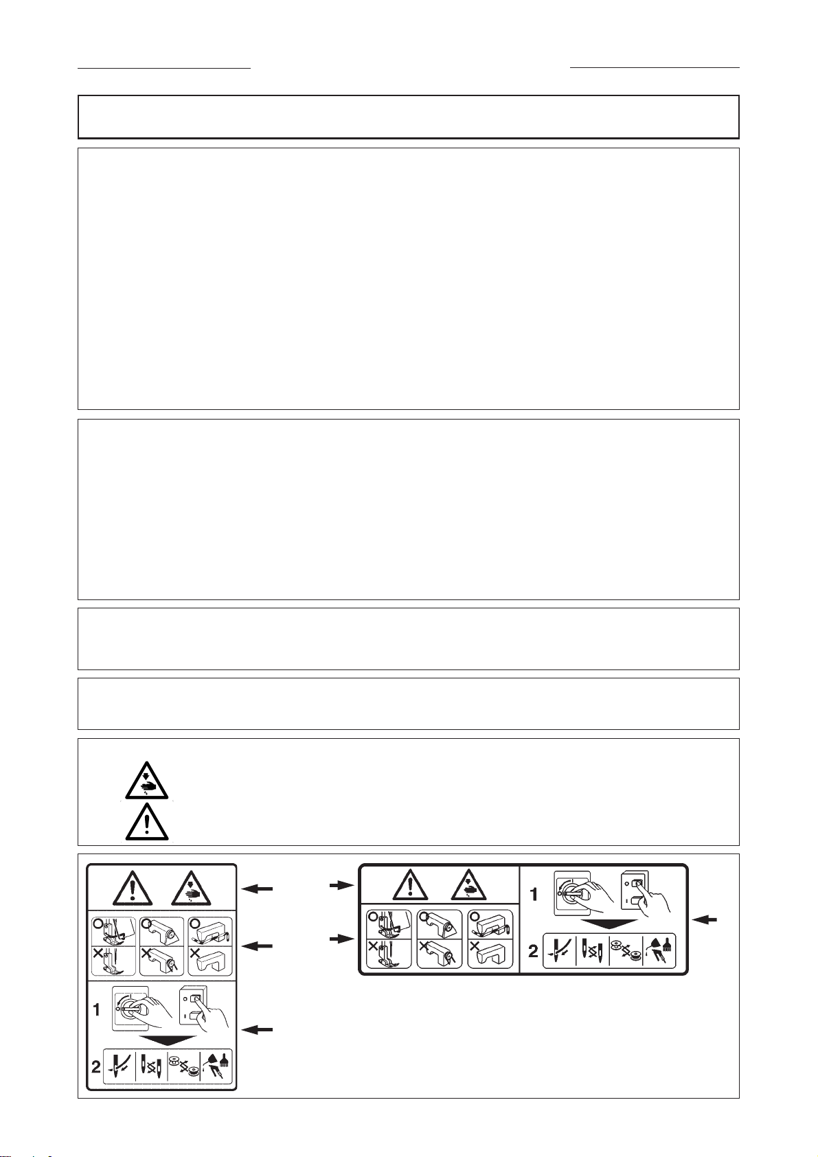
19. Warning hints are marked with the two shown symbols.
Danger of injury to operator or service staff
Items requiring special attention
1
1
3
2
2
1 • There is the possibility that slight to serious injury or death may be caused.
• There is the possibility that injury may be caused by touching moving part.
3
2 • To perform sewing work with safety guard.
• To perform sewing work with safety cover.
• To perform sewing work with safety protection device.
3 • Turn OFF the power and perform “threading”, “replacement of bobbin or
needle”, “cleaning”, “adjustment” and “lubrication”.
i
Page 4
FOR SAFE OPERATION
1. To prevent possible accidents due to electric shocks, neither open the cover of
motor electrical box nor touch the component(s) inside the electrical box.
2. Make sure of the needle entry after changing the pattern. Should the pattern protrude
from the work clamp check, needle interferes with the work clamp check resulting in
the danger of occurrence of needle breakage or the like. In addition, check that the
work clamp check which has been set corresponds to that which has been installed
on the sewing machine.
1. In case nothing is displayed in the operation panel even when the power switch is
turned ON, turn OFF the power switch and check the power voltage and phase.
2. To avoid personal injury, never put your fingers under the thread take-up lever, cloth
presser, cloth cutting knife, or needle when you turn the power switch ON or operate
the sewing machine.
3. To protect against possible accidents due to abrupt startup of the machine, turn
OFF the power switch before tilting the machine head or removing the motor cover.
4. To avoid personal injury, never bring your fingers, hair or clothing close to V belt,
cloth cutting knife or motor during operation, and never place anything on any of
these parts.
5. To avoid personal injury, never operate the machine with the motor cover, eye
protection cover, or any other safety devices removed.
6. To avoid personal injury, be careful never to allow your fingers to go inside the
machine when tilting or raising the machine head.
7. To prevent possible accidents due to electric shocks or damaged electrical
component(s), always turn OFF the power switch before connecting or disconnecting
the power plug.
8. During thunder and lightning storms, stop your work and disconnect the power
from the outlet to ensure safety and prevent possible accidents due to damaged
electrical component(s).
9. If the machine is suddenly moved from a cold place to a warm place, dew
condensation may result. If this occurs, be sure to confirm that there are no potentially
dangerous water drops in the machine before turning it on in order to prevent possible
accidents due to damaged electrical component(s).
10. In the event of a power failure, be sure to turn OFF the power to the machine to
protect against damaged electrical components.
11. This is a Class A product. In a domestic environment this product may cause radio
interference in which case the user may be required to take adequate measures.
ii
Page 5

CONTENTS
蠢 . IMPORTANT SAFETY INSTRUCTIONS ....................................................................... 1
蠡 . SPECIFICATIONS ......................................................................................................... 1
1. Subclass ................................................................................................................................................1
2. Specifications........................................................................................................................................ 1
3. Standard sewing shape list.................................................................................................................. 2
4. Configuration ........................................................................................................................................ 3
蠱 . INSTALLATION ............................................................................................................. 4
蠶 . PREPARATION BEFORE OPERATION ..................................................................... 12
1. Lubrioation ..........................................................................................................................................12
2. Inserting the needle ............................................................................................................................ 12
3. Threading the needle-thread.............................................................................................................. 13
4. Threading the bobbin case ................................................................................................................13
5. Adjusting the bobbin thread tension ................................................................................................14
6. Installation of bobbin case................................................................................................................. 14
7. Installing the knife .............................................................................................................................. 15
蠹 . OPERATION OF THE SEWING MACHINE ................................................................. 16
1. Explanation of the operation panel switch .......................................................................................16
2. Basic operation of the sewing machine ........................................................................................... 18
3. How to use the pedal .......................................................................................................................... 18
4. Input of the presser type .................................................................................................................... 20
5. Performing pattern selection ............................................................................................................. 21
6. Changing needle thread tension .......................................................................................................22
7. Performing re-sewing ......................................................................................................................... 23
8. Winding bobbin thread .......................................................................................................................24
9. Using the counter ............................................................................................................................... 25
10. Using the initial value pattern ............................................................................................................26
11. Changing sewing data ........................................................................................................................27
12. Method of setting sewing data with/without edit .............................................................................28
13. Sewing data list ...................................................................................................................................29
14. Copying sewing pattern .....................................................................................................................35
15. Using pattern register key.................................................................................................................. 36
16. Using parameter register key ............................................................................................................ 37
17. Performing continuous stitching .......................................................................................................38
18. Performing cycle stitching .................................................................................................................40
19. Explanation of plural motions of knife.............................................................................................. 42
20. Method of changing memory switch data ........................................................................................43
21. Memory switch data list ..................................................................................................................... 44
蠧 . MAINTENANCE .......................................................................................................... 48
1. Adjusting the needle-to-hook relation ..............................................................................................48
2. Adjusting the needle thread trimmer ................................................................................................49
3. Adjusting the presser bar pressure ..................................................................................................50
4. Adjustment of the bobbin presser unit .............................................................................................50
5. Thread tension ....................................................................................................................................52
6. Cleaning the filter................................................................................................................................ 52
7. Replacing the fuse .............................................................................................................................. 52
蠻 . GAUGE COMPONENTS ............................................................................................. 53
1. Cloth cutting knife .............................................................................................................................. 53
2. Throat plate ......................................................................................................................................... 53
3. Presser .................................................................................................................................................53
衄 . ERROR CODE LIST .................................................................................................... 54
衂 . TROUBLES AND CORRECTIVE MEASURES ........................................................... 57
衒 . DRAWING OF THE TABLE ......................................................................................... 59
衙 . INITIAL VALUE DATA FOR EACH SHAPE TABLE .................................................... 60
iii
Page 6
1.
IMPORTANT SAFETY INSTRUCTIONS
1) Never operate the machine unless the oiling tank has been properly lubricated.
2) Be sure to remove any dust from the hook or bobbin thread cutting knife section at the end of the day,
and check the amount of oil remaining.
3) Be sure to return the activating pedal to the home position after the machine has started to run.
4) A safety switch is installed so that this sewing machine can not be operated in the state that the machine
head is tilted. When operating this sewing machine, turn the power switch ON after setting the sewing
machine to the bed base properly.
2. SPECIFICATIONS
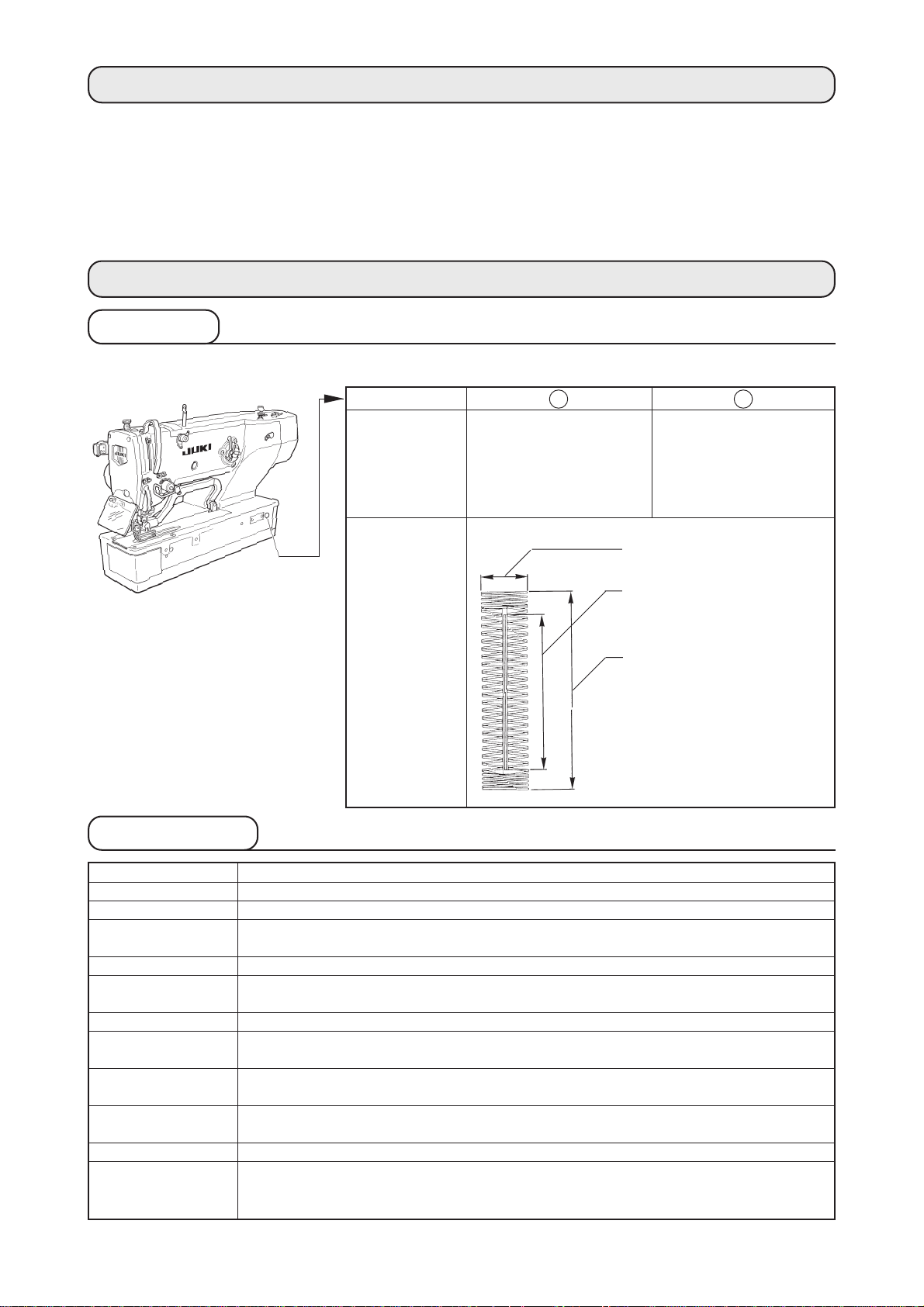
1. Subclass
Computer-controlled, high-speed, lockstitch buttonholing machine, LBH-1790, has the subclass machines below.
2. Specifications
Subclass
Major
application
Buttonholing
size
S
Buttonholing of cloth
such as men’s shirts,
blouses, work uniforms,
ladies' wear, etc.
Standard : Max. 5 mm
Special type part : Max. 10 mm
Knife size used :
6.4 to 31.8 mm (1/4' to 1-1/4')
Buttonholing sewing length
Standard : Max. 41 mm
Special type part : Max. 120 mm
K
Buttonholing of knits
such as knitted
underwear, sweaters,
cardigans, jersey, etc.
Sewing speed
Needle
Hook
Needle rocking drive
method
Feed drive method
Presser lifting drive
method
Lift of presser foot
Cloth cutting knife
drive method
Standard sewing
shape
Number of patterns
stored in memory
Motor used
Noise
Standard speed : 3,600 rpm (Max. : 4,200 rpm) (Max. : 3,300 rpm when dry hook is used)
DPX5 #11J to #14J
DP type full-rotary hook
Drive by stepping motor
Drive by stepping motor
Drive by stepping motor
14 mm (Optional setting available) Max. : 17 mm (At the time of needle up by reverse run)
By double-acting solenoid drive
30 kinds
99 patterns
Single phase 220/230/240 V, 3-phase 200 to 240 V, 1000 VA
Workplace-related noise at sewing speed
n = 4,000 min
Noise measurement according to DIN 45635-48-A-1.
–1
: LPA
≦ 83 dB(A)
− 1 −
Page 7

3. Standard sewing shape list
(1) Square type
PANEL
DISPLAY
(7) Eyelet square type
PANEL
DISPLAY
(13) Semilunar square
type
(2) Round type
PANEL
DISPLAY
(8) Eyelet radial type
PANEL
DISPLAY
(14) Semilunar straight
bar-tacking type
(3) Radial square type
PANEL
DISPLAY
(9) Eyelet straight bar-
tacking type
PANEL
DISPLAY
(15) Semilunar taper bar-
tacking type
(4) Radial type
PANEL
DISPLAY
(10) Eyelet taper bar-
tacking type
PANEL
DISPLAY
(16) Eyelet semilunar
type
(5) Radial straight bar-
tacking type
PANEL
DISPLAY
(11) Semilunar type
PANEL
DISPLAY
(17) Eyelet round type
(6) Radial taper bar-tacking
type
PANEL
DISPLAY
(12) Round square type
PANEL
DISPLAY
(18) Square radial type
PANEL
DISPLAY
(19) Square semilunar
type
PANEL
DISPLAY
(25) Semilunar radial type
PANEL
DISPLAY
PANEL
DISPLAY
(20) Square round type
PANEL
DISPLAY
(26) Semilunar round
type
PANEL
DISPLAY
PANEL
DISPLAY
(21) Square straight bar-
tacking type
PANEL
DISPLAY
PANEL
DISPLAY
(22) Square taper bar-
tacking type
PANEL
DISPLAY
PANEL
DISPLAY
(23) Radial semilunar
type
PANEL
DISPLAY
(24) Radial round type
PANEL
DISPLAY
PANEL
DISPLAY
(27) Bar-tacking (28) Bar-tacking, right cut (29) Bar-tacking, left cut (30) Bar-tacking, center cut
PANEL
DISPLAY
PANEL
DISPLAY
PANEL
DISPLAY
PANEL
DISPLAY
− 2 −
Page 8
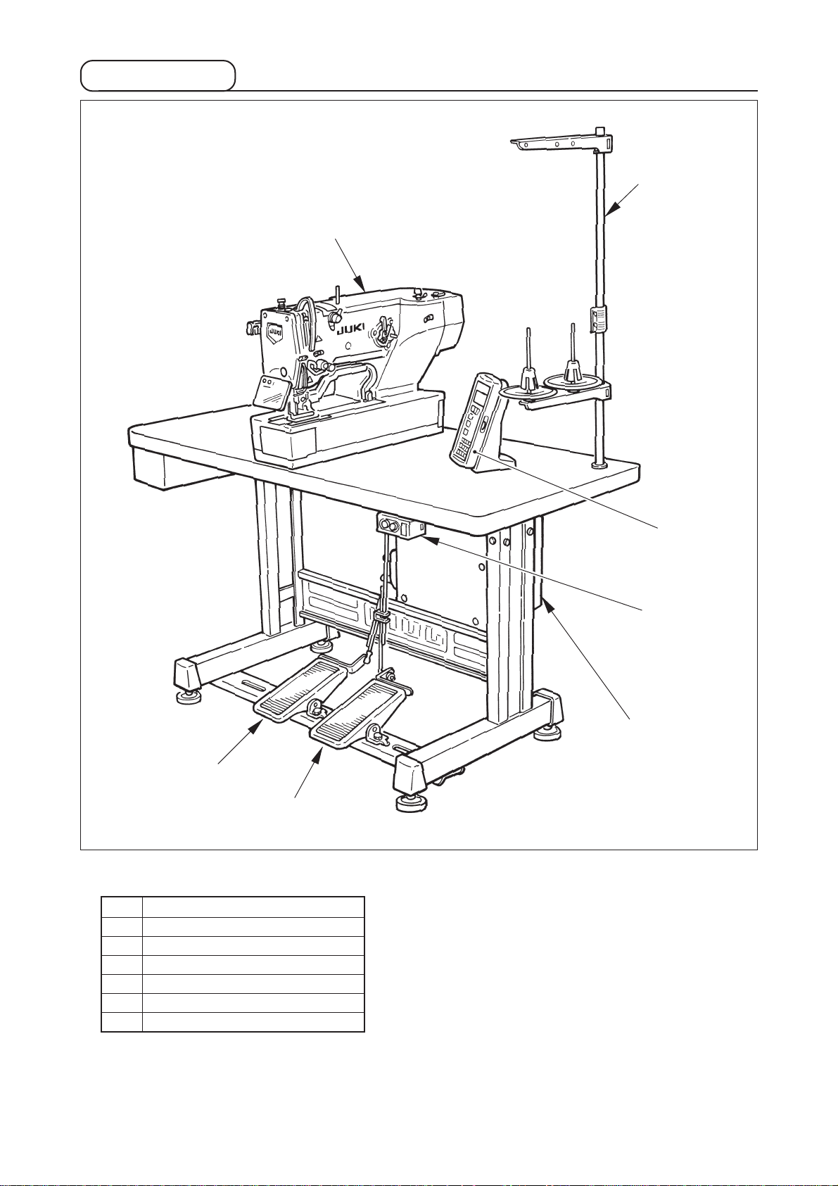
4. Configuration
u
w
t
y
LBH-1790consists of the following components.
q Power ON/OFF switch
w Machine head (LBH-1790)
e Operation panel
r Control box (MC-601)
t Presser lifting pedal
y Starting pedal
u Thread stand device
e
q
r
− 3 −
Page 9
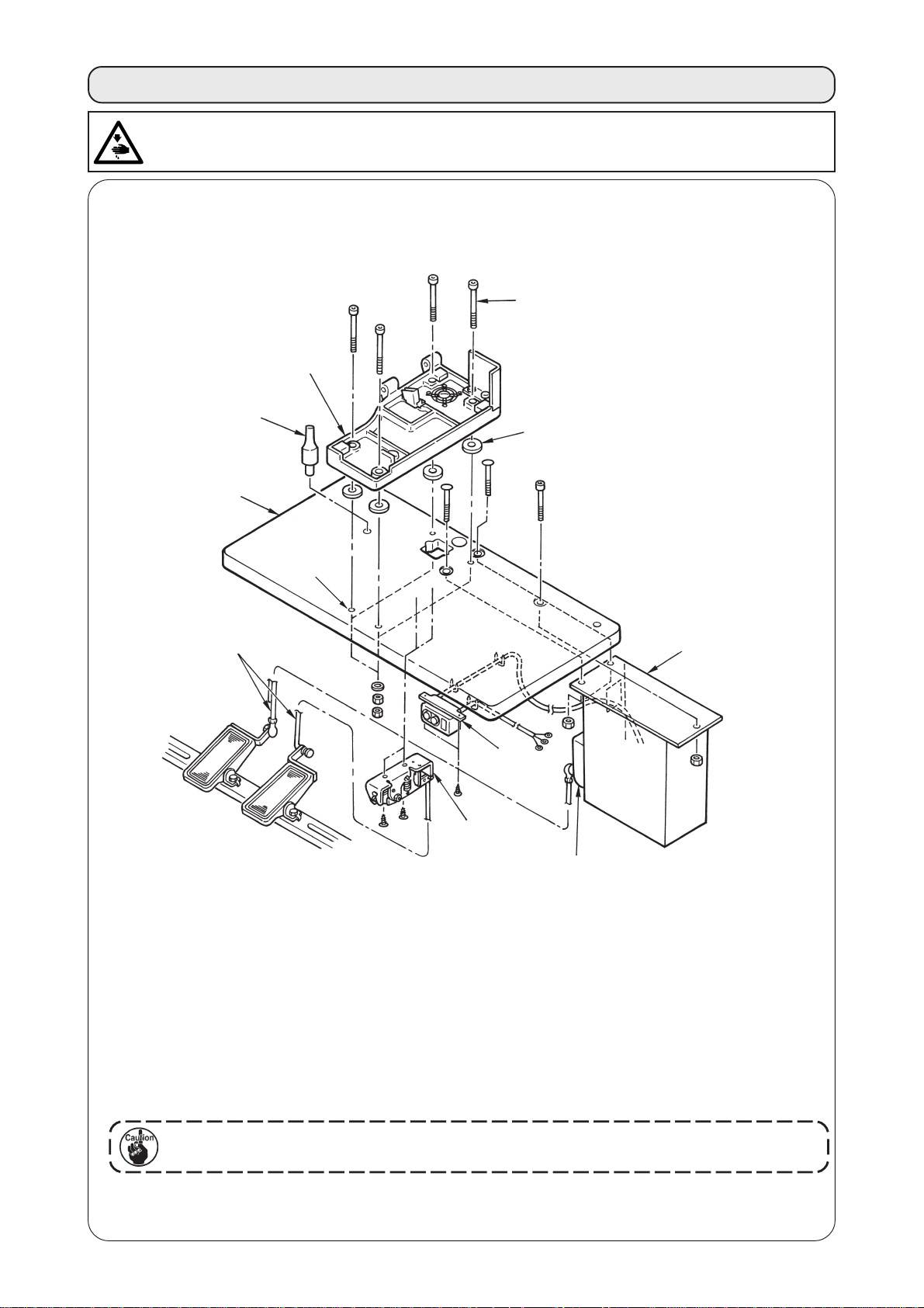
3. INSTALLATION
WARNING :
To prevent possible accidents caused by the fall of the sewing machine, perform the work by two persons
or more when the machine is moved.
(1) Set-up of the table
r
!1
q
i
u
t
y
w
e
o
!0
1) Securely install control box w and power switch e on table q.
2) Securely fix the respective power cables of power switch e.
3) Pass four bed base fixed screws !1 through bed base r.
4) Set rubber cushions t to holes y (4 places) for fixing bed base and fix bed base r.
5) Fix head support bar u on table q.
6) After placing the sewing machine main unit on bed base r, connect pedal (right side) to pedal switch
o, and pedal (left side) to pedal sensor !0 respectively with connecting rods i which have been
supplied as accessories.
Adjust the positions of the pedals so that connecting rods i and control box w do not
come in contact with each other.
− 4 −
Page 10
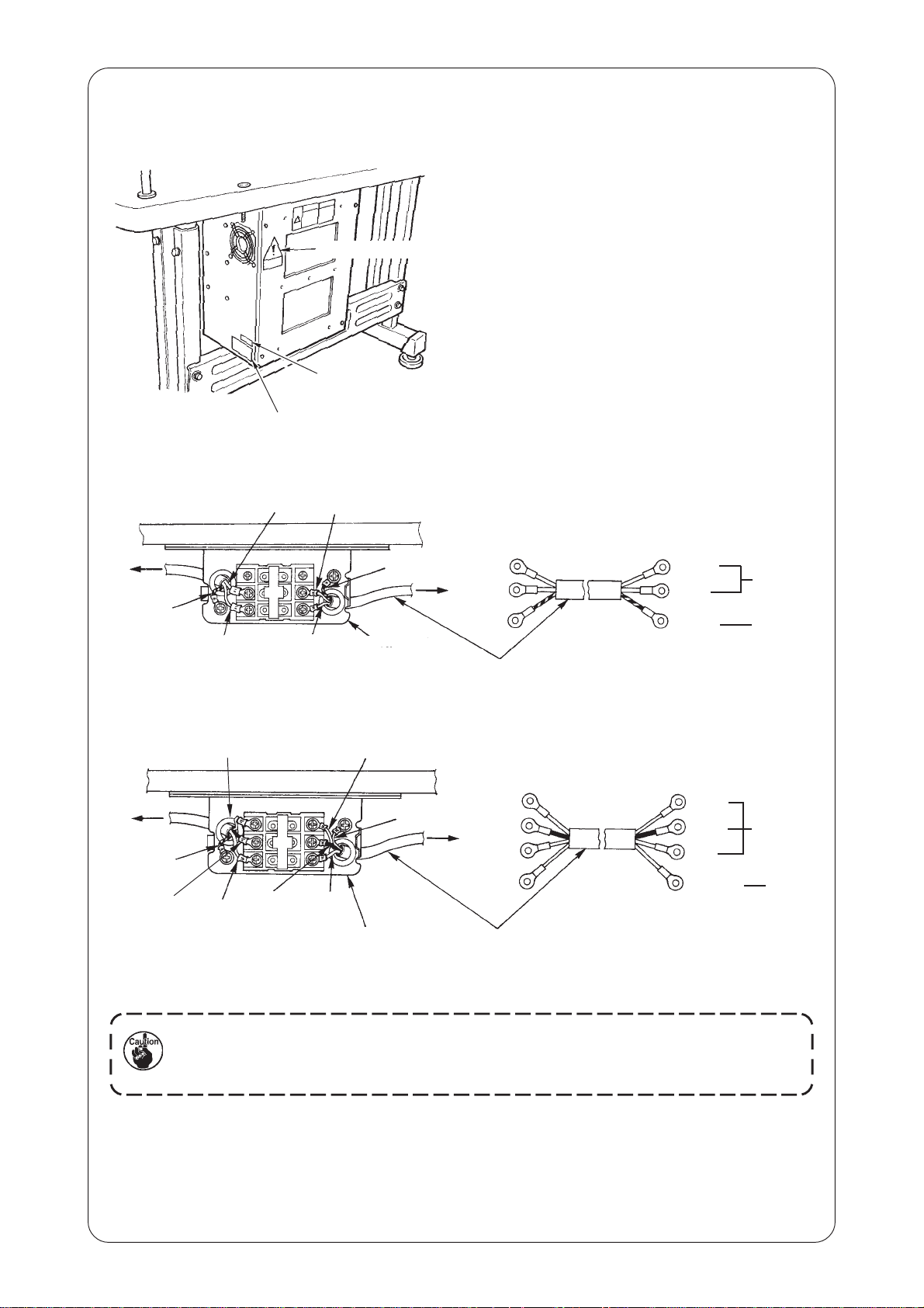
(2) Connecting the power source cord
• Voltage specifications
Power source specifications are indicated on the
voltage indication seal. (3-phase type only)
For other type machines, power source specifications
are indicated on the voltage caution seal and the
rating label.
Voltage caution seal
Voltage indication seal (3-phase type only)
Rating label
• Connecting single phase 200V, 220V, 230V and 240V
Light blue
Table
Control box
Green/Yellow
Brown
Light blue
Brown
Green/Yellow
Power switch
Connect the cord in accordance with the
specifications.
Plug
Power source cord
Brown
Light
blue
Green/
Yellow
AC200 V
AC220 V
AC230 V
AC240 V
GND
• Connecting three phase 200V, 220V and 240V
Table
Control box
Green/Yellow
Black
White
Red
Black
White
Green /
Yellow
Red
Power switch
1. Never use under the wrong voltage and phase.
2. When changing the voltage, refer to the item of "Changing the voltage of 100 /
200V".
Plug
Power source cord
White
Black
Red
Green /
Yellow
AC200 V
AC220 V
AC240 V
GND
− 5 −
Page 11
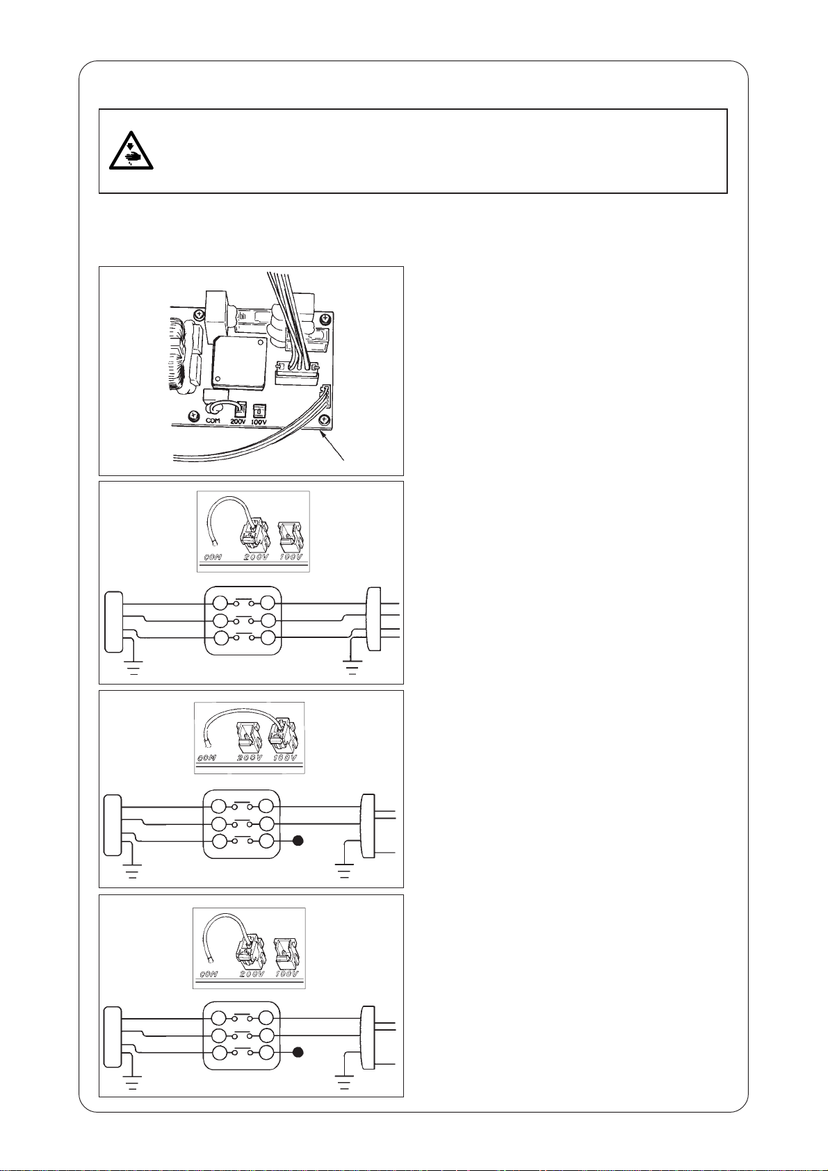
(3) Changing the voltage of 100 / 200V
WARNING :
To prevent personal injuries caused by electric shock hazards or abrupt start of the sewing
machine, carry out the work after turning OFF the power switch and a lapse of 5 minutes or
more. To prevent accidents caused by unaccustomed work or electric shock, request the electric
expert or engineer of our dealers when adjusting the electrical components.
It is adaptable to the voltage of single phase 100V to 120V/3-phase 200V to 240V by changing the
voltage changeover connector mounted on FLT p.c.b.
(Caution) When the changing procedure is wrong, the control box will be broken. So, be very
careful.
Changing procedure of the changeover connector
1. Turn OFF the power source with the power
switch after confirming that the sewing machine
has stopped.
2. Draw out the power cord from the power plug
socket after confirming that the power switch is
turned OFF. Then wait for five minutes or more.
3. Remove the front cover.
4. Remove four screws fixing the rear cover of the
control box and slowly open the rear cover.
A. In case of using with 3-phase 200V to 240V
1
A
• Changing the changeover connector
Connect to 200V the 100/200V changeover
connector of FLT p.c.b. 1 located on the side
of the Box Side of the control box.
• Connect the crimp style terminal of AC input cord
to the power plug as shown in the figure.
B
C
WHITE
BLACK
RED
GREEN/
YELLOW
WHITE
BLACK
RED
GREEN/
YELLOW
WHITE
BLACK
RED
GREEN/
YELLOW
WHITE
BLACK
RED
GREEN/
YELLOW
WHITE
BLACK
RED
GREEN/
YELLOW
WHITE
BLACK
RED
GREEN/
YELLOW
(Plug side)
(Plug side)
(Plug side)
B. In case of using with single phase 100V to 120V
• Changing the changeover connector
Connect to 100V the 100/200V changeover
connector of FLT p.c.b. 1 located on the side
of the Box Side of the control box.
• Connect the crimp style terminal of AC input cord
to the power plug as shown in the figure.
(Caution) Securely perform the insulation
treatment to the red terminal which
is not used with insulation tape or
the like.
(When the insulation is insufficient,
there is a danger of electric shock or
leakage current.)
C. In case of using with single phase 200V to 240V
• Changing the changeover connector
Connect to 200V the 100/200V changeover
connector of FLT p.c.b. 1 located on the side
of the Box Side of the control box.
• Connect the crimp style terminal of AC input cord
to the power plug as shown in the figure.
(Caution) Securely perform the insulation
treatment to the red terminal which is
not used with insulation tape or the
like.
(When the insulation is insufficient,
there is a danger of electric shock or
leakage current.)
5. Check that the change has been performed without
fail before closing the rear cover.
6. Be careful that the cord is not pinched between
the rear cover and the control box main unit. Close
the rear cover while pressing the lower side of rear
cover, and tighten four screws.
− 6 −
Page 12
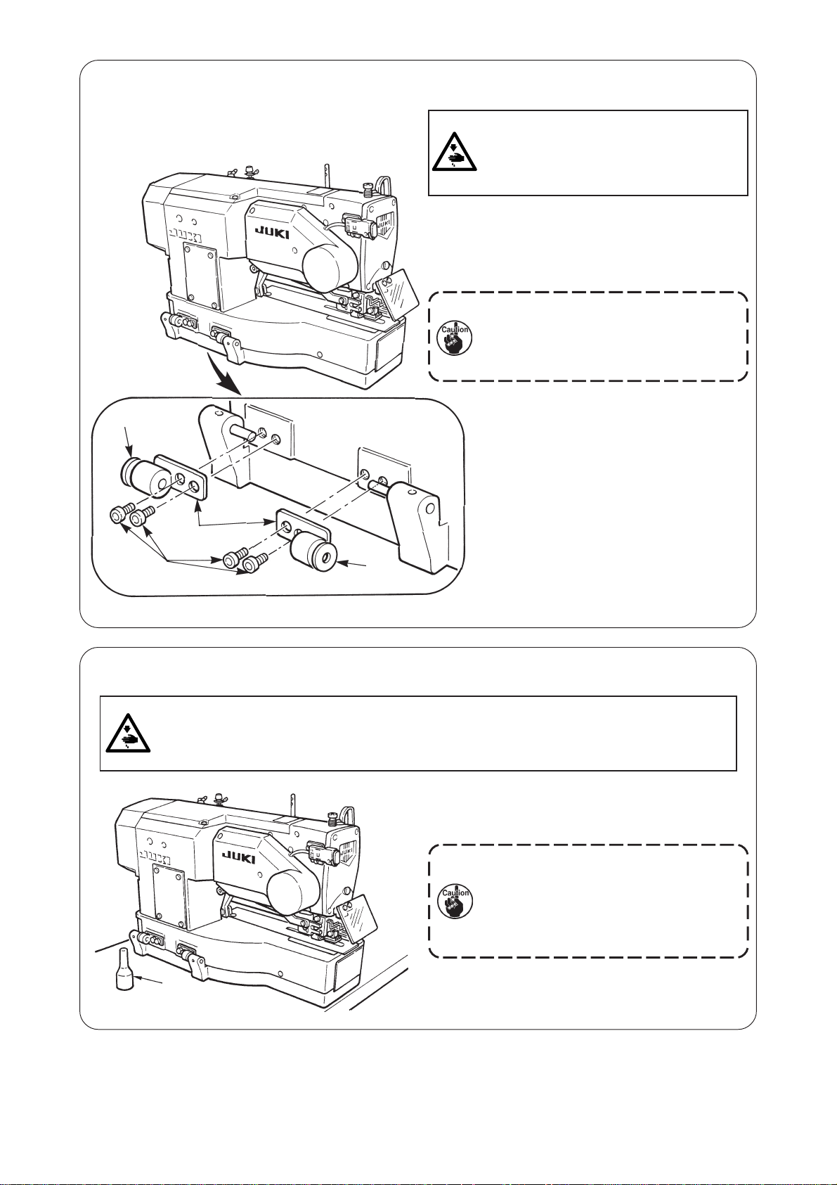
(4) Installing the sewing machine main unit
1) Place hinge plates q and shaft bearings w-1
w-1 (rubber)
WARNING :
To prevent possible accidents caused by the
fall of the sewing machine, perform the work
by two persons or more when the machine
is moved.
(rubber) and w-2 (metal) in two places on the
head base and fix the hinge plates to the machine
head with setscrews e in two places.
When the rubber hinge and metal fitting
hinge are installed in reverse order, it is
dangerous since the sewing machine
shakes when it is tilted. So, be careful.
q
e
w-2
(metal)
(5) Tilting the sewing machine head
WARNING :
When tilting/raising the sewing machine head, perform the work so as not to allow your fingers to
be caught in the machine. In addition, to avoid possible accidents caused by abrupt start of the
machine, turn OFF the power to the machine before starting the work.
When tilting the sewing machine head, tilt quietly the
sewing machine until head support bar q comes in
contact with it.
1. Make sure that sewing machine head
support bar q is placed on the table
before tilting the sewing machine.
2. To protect fall-down, be sure to tilt the
sewing machine in a level place.
q
− 7 −
Page 13
(6) Connecting the safety switch connector
w
q
Cord clamp
(7) Installing the hook oil shield plate
1) Connect safety switch connector q
with connector w located on the
machine head side.
q
e
w
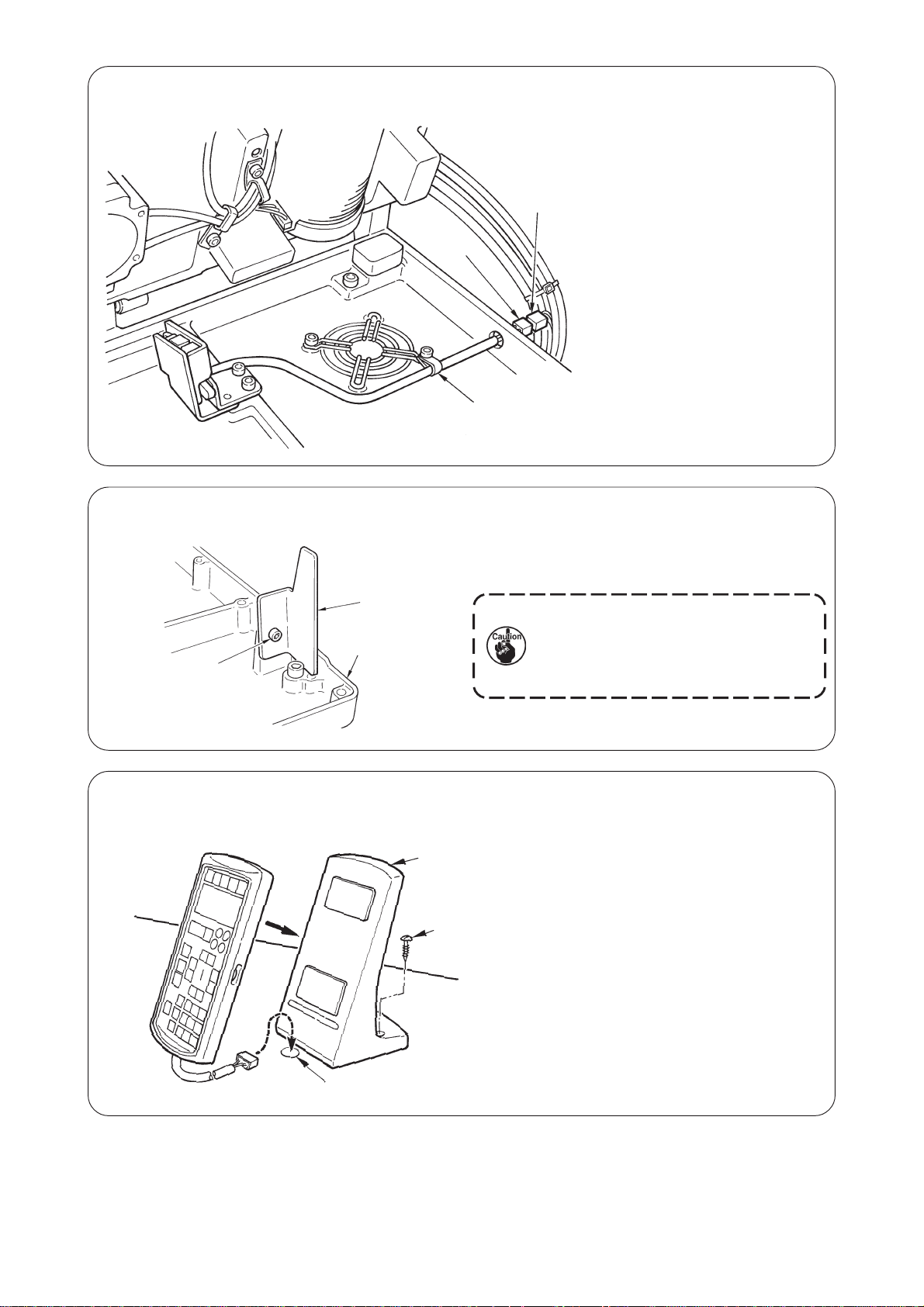
(8) Installing the operation panel
q
Install hook oil shield plate q onto bed base e with
setscrew w.
Fix the sewing machine so that it does
not come in contact with hook oil shield
plate q when raising/tilting the sewing
machine.
Fix operation panel attaching plate q on the table
with woodscrew w and pass the cable through hole
e in the table.
w
e
− 8 −
Page 14

(9) Connecting the cords
Perform the connection of the cords as shown in the figure below.
CN14
Sewing machine head
CN16
CN34
MAIN circuit
board
SDC circuit board
CN16
SDC circuit
CN14
CN44
CN14
q
board
CN42
CN37
CN38
CN39
CN41
Cord
clamp A
CN16
CN37
CN38
CN42
CN39
Operation panel
CN41
CN34
Electric bobbin winding device (optional)
CN44
1) Pass 4 cords (CN38, 39, 41, and 42) connecting
to the right side among the cords connecting to
MAIN circuit board through cord clamp A as shown
in the figure, and connect them to the respective
connectors. Connect CN37 to the connector
without passing through cord clamp A.
In addition, when using the electric bobbin winding
device (optional), similarly pass the cord of the
bobbin winding device through the cord clamp and
connect it to CN44.
2) Directly connect the cord from the operation panel
connecting to the left side of MAIN circuit board
to CN34.
3) Connect the cords connecting to SDC circuit board
directly to CN14 and CN16.
4) Fix the earth wire with the setscrew q.
− 9 −
Page 15
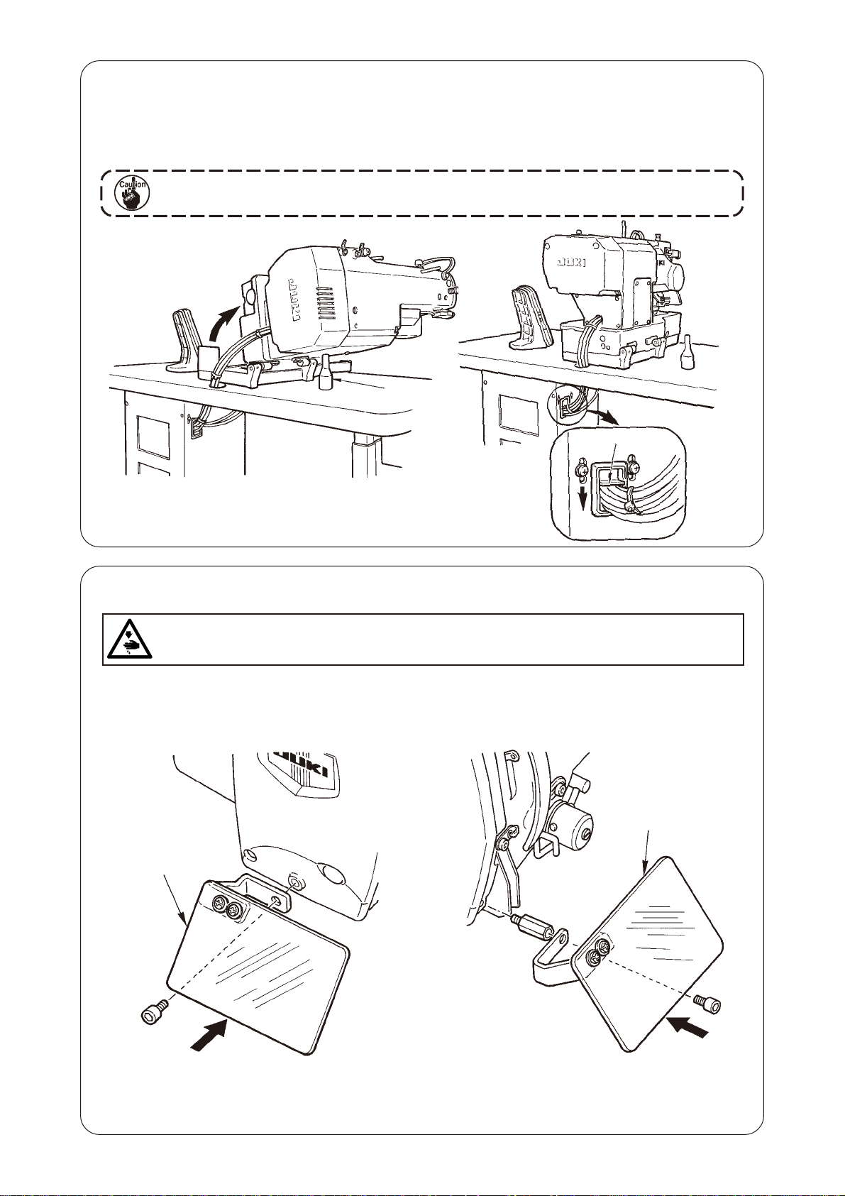
(10) Managing the cord
1) Slowly tilting the sewing machine, check that the cords are not forcibly pulled.
2) Fix the cords with cord setting plate 1 as shown in the figure.
When you tilt the sewing machine, make sure that the sewing machine head support
bar 2 is placed on the table.
2
1
(11) Installing the eye protection cover
WARNING :
Be sure to attach this cover to protect the eyes from the disperse of needle breakage.
Be sure to install and use eye protection cover 1 and use the sewing machine.
When placed longitudinally When placed horizontally
1
1
Operator
Operator
− 10 −
Page 16
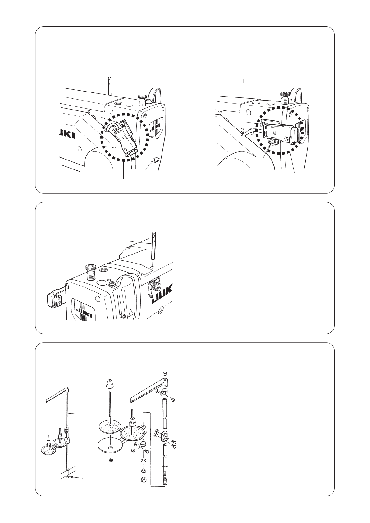
(12) Fixing the temporary stop switch
The temporary stop switch has been in the state as shown in figure A at the time of delivery.
Loosen setscrew q and set the switch in the state as shown in figure B, and fix it with setscrew q together
with setscrew w supplied with the machine.
q
q
\
w
B
A
(13) Thread guide rod
Thread guide rod
(14) Installing the thread stand
w
Securely fit the thread guide rod so that two side holes
in the thread guide rod face the thread guide.
1) Assemble the thread stand, and set it in the hole
in the top right corner of the machine table.
2) Tighten locknut q to fix the thread stand.
3) When ceiling wiring is possible, pass the power
cable through spool rest rod w.
q
− 11 −
Page 17
4. PREPARATION BEFORE OPERATION
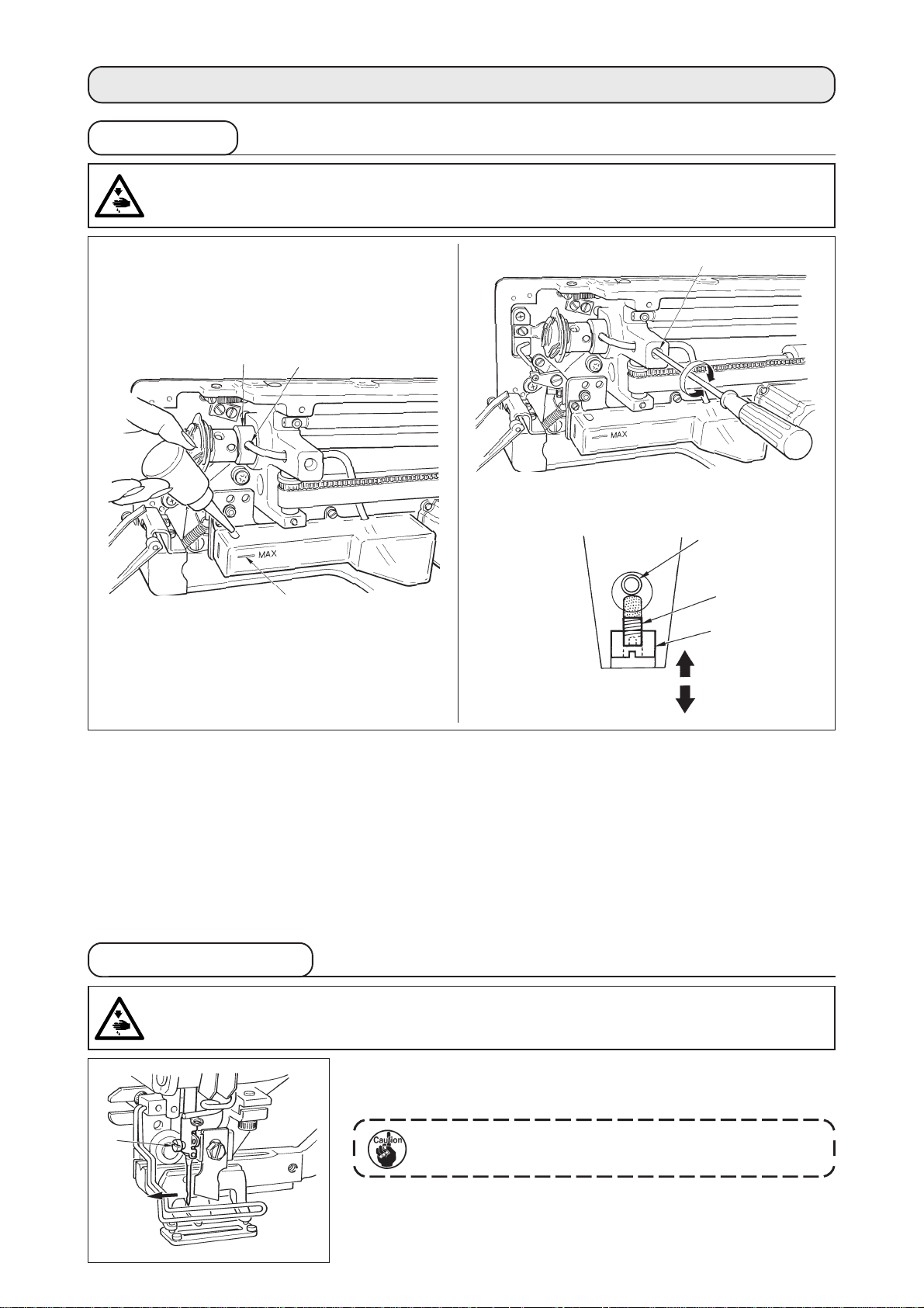
1. Lubrioation
WARNING :
To protect against possible personal injury due to abrupt start of the machine, be sure to start the
following work after turning the power off and ascertaining that the motor is at rest.
w
e
r
q
t
Detailed diagram of oil amount adjusting section
Oil pipe
e
w
Decrease
Oil amount
Increase
1) Lubricating oil to oiling tank
○
Fill the oiling tank with New Defrix Oil No.1 up to the level indicated by “MAX” q.
2) Adjusting the lubrication for the sewing hook
○
Adjust the amount of oil supplied to the sewing hook by loosening lock nut w and turning oil amount
adjusting screw e.
○
Amount of supplied oil is reduced when turning the screws e clockwise.
○
Fix the screw with lock nut w after adjusting the lubrication for the sewing hook.
○
When you first operate your sewing machine after set-up or after an extended period of disuse, remove
the bobbin case and apply a few drops of oil to the hook race. In addition, apply a few drops oil from oiling
hole r in hook driving shaft front metal t to soak the inside felt in oil.
2. Inserting the needle
WARNING :
To protect against possible personal injury due to abrupt start of the machine, be sure to start the
following work after turning the power off and ascertaining that the motor is at rest.
q
A
Hold needle with its recessed part facing toward the operator side A,
insert the needle fully into the needle clamping hole, and tighten needle
setscrew q. Use a DPx5-(#11J, #14J).
When attaching the needle, turn OFF the power to the
motor.
− 12 −
Page 18
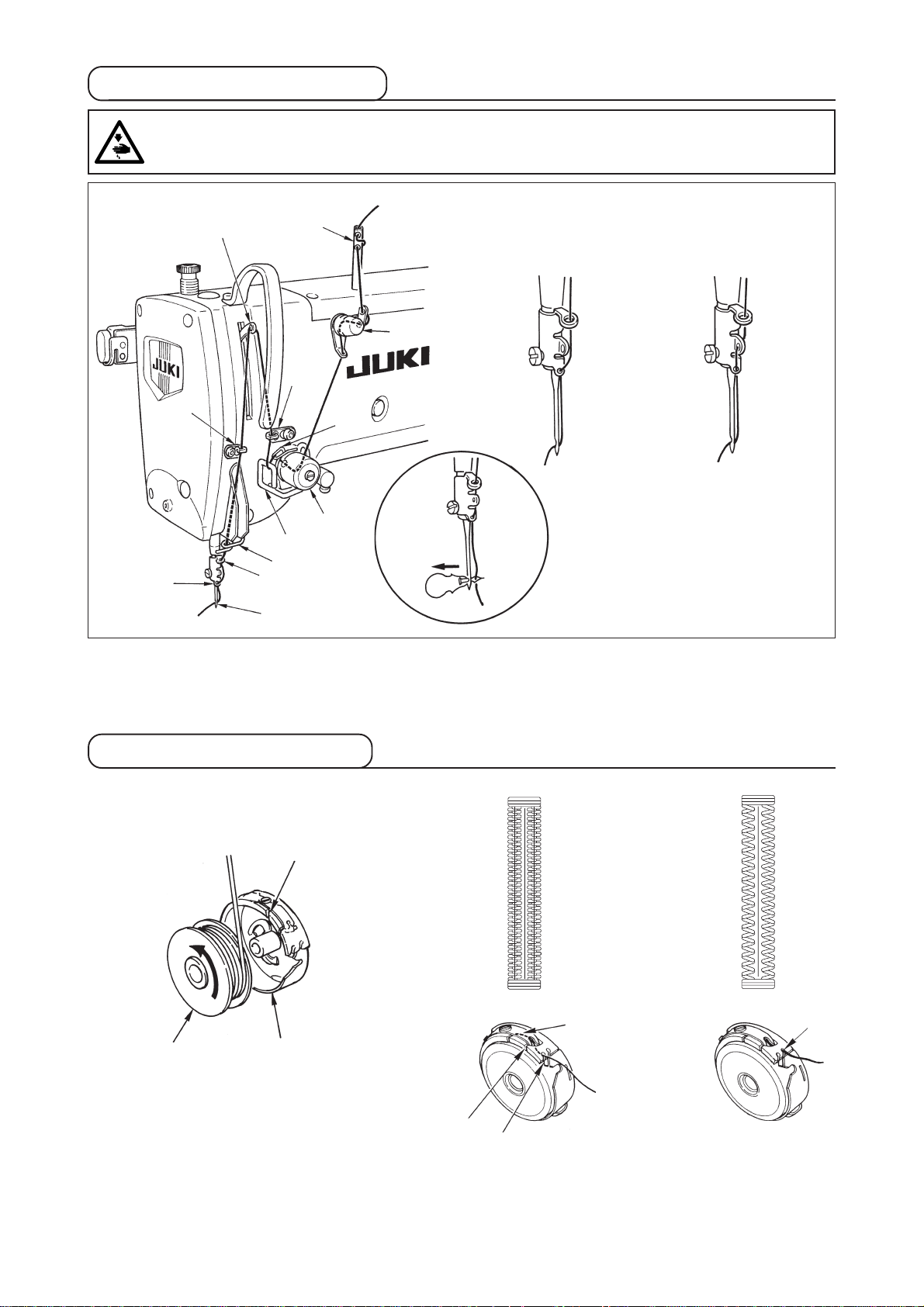
3. Threading the needle-thread
WARNING :
To protect against possible personal injury due to abrupt start of the machine, be sure to start the
following work after turning the power off and ascertaining that the motor is at rest.
!2
o
t
y
q
e
r
w
Cotton thread, spun thread
Synthetic filament thread
!1
u
i
!0
Pass the needle thread in the order q to !2 as shown in the figures.
The threading can be done easily by using the needle threader supplied with the machine.
Change the thread guide threading method according to the thread to be used.
4. Threading the bobbin case
Whip stitchPurl stitch
q
w
Bobbin
Rotating direction of bobbin and threading
1) Fit the bobbin so that it rotates in the direction of the arrow.
2) Pass the thread through thread slit q, then through under the tension spring w, again through thread
slit e, and pull the thread from r.
3) Threading at r for purl stitching is different from that for whip stitching. So, be careful.
Bobbin case
e
r
r
− 13 −
Page 19
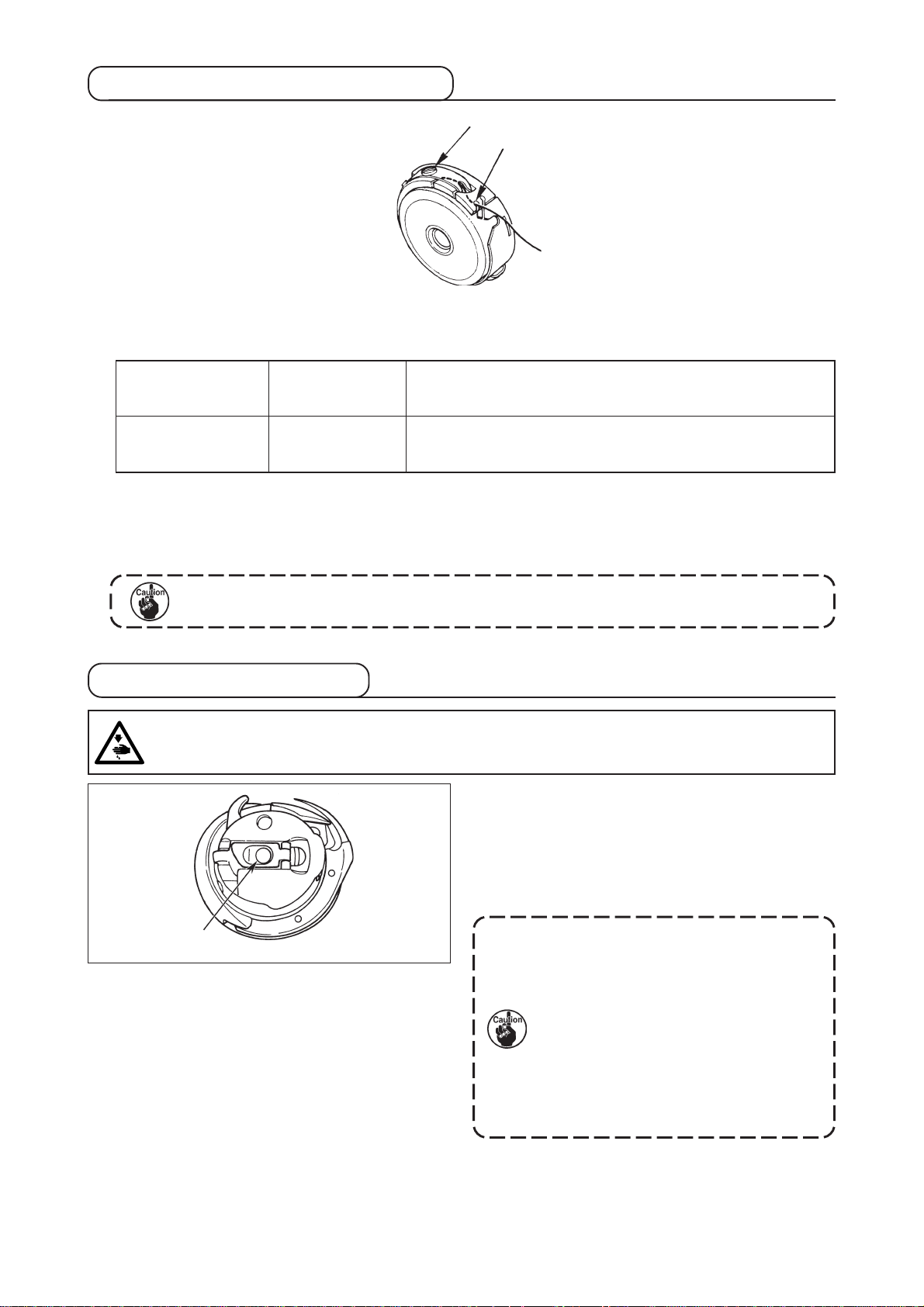
5. Adjusting the bobbin thread tension
w
q
Adjust the bobbin thread tension as given below when the bobbin thread is pulled up at the position where
thread slit q of bobbin case comes up.
To such an extent that bobbin case quietly comes down when holding
Purl stitch
Whip stitch
Turning tension adjust screw w clockwise will increase bobbin thread tension, and turning it counterclockwise
will decrease the tension.
Adjust the bobbin thread tension to lower for synthetic filament thread, and to higher for spun thread. The
thread tension is higher by approximately 0.05N when the bobbin case is set to the hook since idle-prevention
spring is provided.
0.05 to 0.15N
0.15 to 0.3N
thread end coming from bobbin case and shaking it quietly up and
down.
To such an extent that bobbin case barely comes down when holding
thread end coming from bobbin case and shaking it somewhat
strongly.
When bobbin thread tension is adjusted, check the needle thread tension setting of the
memory switch. (See P.44.)
6. Installation of bobbin case
WARNING :
To protect against possible personal injury due to abrupt start of the machine, be sure to start the
following work after turning the power off and ascertaining that the motor is at rest.
q
1) Lift up and hold bobbin case latch lever between
two fingers.
2) Push the bobbin case into the hook so that it is
supported by the hook shaft q and then snap in
the latch lever.
Press the bobbin case until the predetermined
position is reached, and it will click.
1. If the bobbin case is out of the
predetermined position, it can jump
out from the hook to cause the needle
thread to tangle on the hook shaft.
Check to be sure that the bobbin case
is properly installed in the correct
position.
2. There is a difference in the shape of
bobbin case between the standard
hook and the dry one. They have
nothing in common with each other.
− 14 −
Page 20
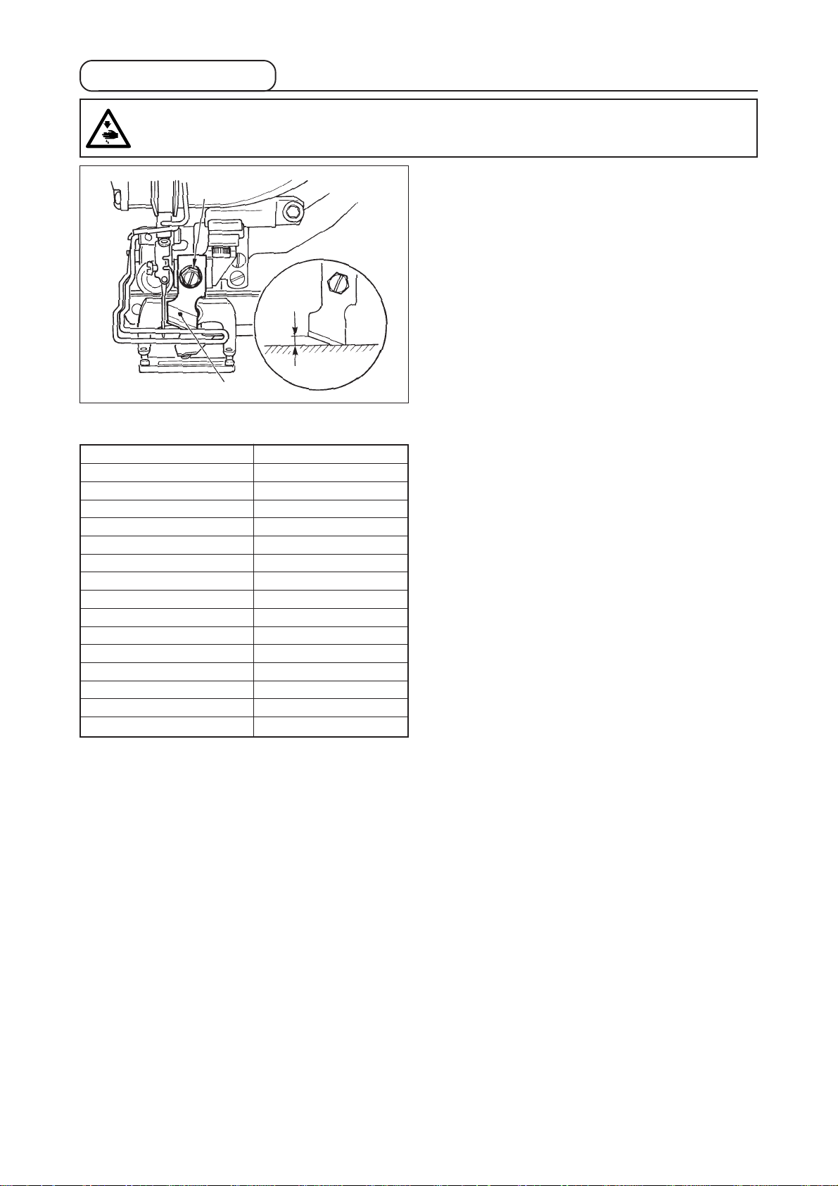
7. Installing the knife
WARNING :
To protect against possible personal injury due to abrupt start of the machine, be sure to start the
following work after turning the power off and ascertaining that the motor is at rest.
w
1 to 2 mm
q
Inch → mm CONVERSION TABLE
Knife size Indication of mm
1/4 6.40
3/8 9.50
7/16 11.10
1/2 12.70
9/16 14.30
5/8 15.90
11/16 17.50
3/4 19.10
13/16 20.60
7/8 22.20
1 25.40
1 1/8 28.60
1 1/4 31.80
1 3/8 34.90
1 1/2 38.10
When replacing the knife with a new one, perform as
follows.
1) Knife q can be easily removed together with the
washer when removing knife retaining screw w.
2) Adjust so that the knife, when lowered the knife
bar by hand, is spaced 1 to 2 mm away from the
top surface of the throat plate as illustrated in the
sketch. Then, be sure to place the washer and
tighten the knife retaining screw.
When the cloth cutting knife you have is indicated in
inch, set the cloth cutting length (knife size) in mm using
the inch → mm conversion table. (See P.29.)
− 15 −
Page 21

5. OPERATION OF THE SEWING MACHINE
1. Explanation of the operation panel switch
q
!6
u
i
o
w
e
r
t
y
!0
!1
!7
!8
!9
!2
!3
!4
!5
@3
@4
There are 3 states below according to back-light colors.
Blue : Input mode .......... Data change is possible.
Green : Sewing mode .... Sewing possible state
Yellow : Error state ........ Some error occurs.
@5
@6
@0
@1
@2
@7
@8
#0
@9
− 16 −
Page 22

No.
q
NAME
LCD display
FUNCTION
Various data such as pattern No.,
shape, etc. are displayed.
No.
!6
OVEREDGING
WIDTH key
NAME
FUNCTION
This key selects overedging width
display.
w
READY key
e
RESET key
r
MODE key
t
PRESSER key
y
WINDER key
u
PATTERN NO. key
i
DATA key
Press this key when starting sewing.
Every time this key is pressed, change-
over of sewing ready set state and data
set state can be performed.
Press this key when releasing error,
travelling the feed mechanism to its
initial position, counter resetting, etc.
Press this key when changing data of
the memory switches.
This key lifts or lowers the presser. When
the presser goes up, the needle bar travels
to the origin and when it comes down, the
needle bar travels to the right.
This key is pressed when performing
bobbin winding.
This key selects pattern No. display.
This key selects data display.
!7
BAR-TACKING
WIDTH, LEFT key
!8
BAR-TACKING
WIDTH, RIGHT
key
!9
CLOTH CUT
LENGTH key
@0
CLEARANCE key
@1
KNIFE GROOVE
WIDTH, RIGHT
key
@2
KNIFE GROOVE
WIDTH, LEFT key
@3
COPY key
This key selects left side of bar-tacking
width compensation display.
This key selects right side of bar-tacking
width compensation display.
This key selects cloth cut length display.
This key selects clearance display.
This key selects knife groove width,
right compensation display.
This key selects knife groove width, left
compensation display.
Press this key when copying pattern.
o
COUNTER key
!0
ITEM SELECTION
key
!1
DATA CHANGE
key
!2
SHAPE key
!3
THREAD TENSION AT
PARALLEL SECTION key
!4
THREAD TENSION AT
BAR-TACKING SECTION
key
Thus key selects counter display.
This key selects pattern No., data No.,
etc.
This key changes various data.
This key selects shape display.
This key selects thread tension at
parallel section display.
This key selects thread tension at bar-
tacking section display.
@4
PRESSER
SELECTION key
@5
FORWARD key
@6
BACKWARD key
@7
PATTERN
REGISTRATION key
@8
PARAMETER
REGISTRATION key
@9
Speed variable
resister
This key selects presser type.
This key makes the feed mechanism
travel forward stitch by stitch.
This key makes the feed mechanism
travel backward stitch by stitch.
This is a short cut key that pattern registration
is available. Registration of shortcut to setting
display of an optional pattern is possible.
For the setting procedure, see P.36.
This is a short cut key that parameter registration
is available. Registration of shortcut to setting
display of an optional pattern, sewing
parameter or adjustment data is possible. For
the setting procedure, see P.37.
Speed increases when this is lifted
upward and decreases when this is
lowered downward.
!5
PITCH key
This key selects pitch of parallel
section.
− 17 −
#0
LCDadjustment
variable rsistor
Light and shade of LCD display can be
adjusted.
Page 23

2. Basic operation of the sewing machine
1) Turn ON the power switch.
First, check that presser type A which has been
set is the same as that of the presser actually
mounted. For checking and setting procedures,
refer to 4. Inputting the presser type.
2) Select the pattern No. you desire to sew.
When the power is turned ON, the pattern No. B
which is selected at present flashes on and off.
When you desire to change it, press ITEM
SELECTION key !0 and select the No. you
desire to sew. When you purchase the sewing
machine, pattern No. 1 to 10 described in
11.Changing sewing data have been registered.
Select the pattern No. you sesire to sew from among
these numbers. (The No. with which the pattern
has not been registered is not displayed.)
B
w
q
A
3) Set the sewing machine to sewing possible state.
Press READY key w and the back-light of LCD display q changes from blue color to green color, and
sewing is possible.
!0
4) Start sewing.
Set the sewing product to the presser portion, and operate the pedal to start the sewing machine, and
sewing starts. When you purchase the sewing machine, 2-pedal type has been set. However, pedal operating
procedure can be selected from among three ones. Select the operating procedure you desire and use the
sewing machine. → 3. How to use the pedal
3. How to use the pedal
This sewing machine can be used by selecting the pedal operating procedure from among 3 types below.
Select the operating procedure you desire for working efficiency and use the sewing machine.
(1) Setting procedure of the pedal type
1) Call the pedal type setting parameter.
Press MODE key r for as long as three
seconds in the state of the input mode and memory
switch (level 2) edit screen A is displayed. When
the pedal type selection parameter is not
displayed, press ITEM SELECTION key !0
to select the pedal type.
r
A
2) Select the pedal type
Press DATA CHANGE key !1 and the picture
is changed as shown in the illustration below. Select
the pedal type B you desire.
2-pedal
(Without intermediate position)
1-pedal
B
!0 !1
1-pedal
(With intermediate position)
− 18 −
Page 24

(2) Explanation of pedal motion
2-pedal type
Initial position
Presser : Intermediate position w
or Sewing position e
1) Setting of sewing product
(Presser goes up as high as the
pedal toe down amount of the left
side pedal.)
2) Start of Sewing
(Sewing starts when the right side
pedal is depressed.)
3) End of sewing
(Presser automatically goes up to
Intermediate position w.)
1-pedal
(Without intermediate position)
Initial position
Presser : Maximum position q
1) Setting of sewing product
2) Confirmation of setting of
sewing product
(Presser comes down to Cloth
setting position e when the first
step of the right side pedal is
depressed.)
3) Start of sewing
(Sewing starts when the second
step of the right side pedal is
depressed.)
4) End of sewing
(Presser automatically goes up to
Maximum position q)
1-pedal
(With intermediate position)
Initial position
Presser : Maximum position q
1) Setting of sewing product
2) Confirmation of setting
of sewing product
(Presser comes down to
Intermedite position w when the
first step of the right side pedal is
depressed.)
3)
Confirmation of start of sewing
(Presser comes down to Cloth
setting position e when the second
step of the right side pedal is
depressed.)
4) Start of sewing
(Sewing starts when the third step
of the right side pedal is depressed.)
5) End of sewing
(Presser automatically goes up to
Maximum position q.)
* Height of the respective positions of q to e
described on the left side can be set or changed by
the memory switches.
Cloth
q
w
e
→ 20. Method of changing memory switch data
• Pedal switch setting
Attach or remove the screw shown in the figure according to the setting of the memory switch.
• 2-pedal type
• 1-pedal (Without intermediate position)
Remove the screw.
• 1-pedal (With intermediate position)
Attach the screw.
− 19 −
Page 25

4. Input of the presser type
(1) Setting procedure of the presser type
1) Call the presser type setting parameter.
Press PRESSER SELECTION key @4
memory switch (level 1) edit screen A is displayed.
and
2) Select the presser type.
Press DATA CHANGE key !1 , and the
picture is changed as shown in the illustration
below. Set the presser type B actually mounted on
the sewing machine referring to Table of presser
type below.
Type 1 Type 2 Type 3 Type 5 *
@4
(2) Table of presser type
Set the number in the frame of engraved part number of presser to the type of presser.
Type
Part No. of presser foot
A
B
!1
Type 1
Type 2
Type 3
Type 5 *
B151177 1 000 *
B151177 2 000 *
B151177 3 000 *
–
* Set type 5 when using the presser other than
type 1 to 3. Change Presser size width
and Presser size length of the memory
switch (level 1) to adjust to the presser to be
used.
→ Refer to 20. Method of changing memory
switch data.
* When using type 5 with stitch width of 6 mm or
more and 41 mm or more in length, it is
necessary to replace components such as
presser arm, feed plate, etc.
− 20 −
Page 26

5. Performing pattern selection
(1) Selection from the pattern selection screen
1) Set the mode to the input mode.
When the back-light of LCD display q shows the
input mode in blue color, it is possible to change
the pattern. When the back-light shows the sewing
mode in green color, press READY key w
change over to the input mode.
2) Call the pattern selection screen.
Press PATTERN No. key u , and pattern
selection screen A is displayed.
Pattern No. B which is selected at present flashes
on and off.
3) Select the pattern.
Press ITEM SELECTION key !0 , and the
patterns which have been registered are changed
over in order and displayed. Here, select the No.
you desire to sew.
to
w
q
B
u
!0
A
(2) Selection by means of the register key
This sewing machine can register the pattern No. you desire with the register switch. When the pattern is
registered once, pattern selection can be performed by pressing only the switch.
/ Refer to 15. Using pattern register key.
− 21 −
Page 27

6. Changing needle thread tension
Needle thread tension can be changed while performing trial sewing since the data related to the needle
thread tension can be set by the sewing mode as well.
1) Call thread tension at parallel section
setting data.
Press THREAD TENSION AT PARALLEL
SECTION key !3 , and sewing data edit screen
A is displayed.
B
A
1), 2)
2) Change thread tension at parallel
section.
Press DATA CHANGE key !1
B goes up or comes down and the thread tension
can be changed. The relation between the finish of
sewing and the set value is as shown in the
illustration below. Set the value referring to the
illustration.
, and set value
3) Call thread tension at bar-tacking
section setting data.
Press THREAD TENSION OF BAR-TACKING
SECTION key !4 , and sewing data edit screen
C is displayed.
4) Changing the needle thread tension at
bar-tacking section
Press DATA CHANGE key !1
D goes up or comes down and the thread trension
can be changed. The relation between the finish of
sewing and the set value is as shown in table below.
Set the value referring to the table.
* For the tension other than that at parallel section
and bar-tacking section, refer to 11. Changing
sewing data and 20. Method of changinf
memory switch data.
, and set value
D
C
3), 4)
!1
!3
!4
Set value of tension at q parallel section and w bar-tacking section
Set value on panel
Initial value
Purl stitch
Whip stitch
q Tension at parallel
section
w Bar-tacking tension
q Tension at parallel
section
w Bar-tacking tension
Crest is lowered.
Thread tension
is decreased.
Thread tension
is decreased.
Thread tension
is decreased.
120
35
60
60
Crest is raised.
Thread tension is
increased.
Thread tension is
increased.
Thread tension is
increased.
For the eyelet radial shape, set the bar-tacking tension first to approximately 120 and make the balance of
stitches.
Purl stitch and Whip stitch
Purl stitch
Whip stitch
Whip stitch
Purl stitch
When applying higher tension to the needle thread to permit it to pass straight
through fabric, the purl stitch is formed by the bobbin thread which is pulled over
from both sides to the center line.
Whip stitch
The whip stitch is formed in zigzag showing the needle thread only on top of
fabric, and the bobbin thread on the bottom.
− 22 −
Page 28

7. Performing re-sewing
When stop switch A is pressed during sewing
operation, the sewing machine interrupts sewing
and stops. At this time, error display screen B is
displayed to inform that the stop switch is pressed.
To continue performing sewing from some
point in sewing
Sewing motion stop status
Error display screen B is displayed.
A
B
Error No. Error pictograph
e
1) Release the error.
Press RESET key e to release the error. Then
step motion screen C is displayed.
2) Return the presser.
Press BACKWARD key @6 and the presser
returns stitch by stitch.
Press FORWARD key @5 and the presser
advances stitch by stitch. Return the presser to the
re-sewing position.
3) Start sewing again.
Depress the right side pedal and sewing starts
again.
To perform re-sewing from the start
Sewing motion stop status
Error display screen B is displayed.
1) Release the error.
Press RESET key e to release the error. Then
step motion screen C is displayed.
E
D
@5
@6
* Existing number of stitches/total number of stitches
are displayed in section D.
* Existing sewing command is displayed in section E.
Kinds of commands are :
Sewing
command
Jump feed
command
C
2) Return the presser to the sewing product
setting position.
Press again RESET key e and the presser
returns to the sewing product setting position.
3) Perform again the sewing work from the
start.
− 23 −
Thread trimmer
command
Knife command
Page 29

8. Winding bobbin thread
(1) Winding the bobbin
1) Set the bobbin .
Fit a bobbin fully onto the bobbin winder shaft. Take
the thread from the spool and pass it through the
guides in the numerical order as shown in the figure,
and wind the end of the thread several times around
the bobbin. Then push the bobbin winder trip latch
q in the direction of the arrow mark.
2) Set the mode to the bobbin winding mode.
Press WINDER key y from either input status
or sewing status to enter the bobbin winding mode,
and bobbin winding screen C is displayed.
q
B
A
3) Start bobbin winding.
Depress the right-hand side pedal, and the sewing
machine rotates and starts winding bobbin thread.
4) Stop the sewing machine.
Once the bobbin is wound with the predetermined
amount of thread, bobbin thread guide q is
released. Press WINDER key y or depress
the right-hand side pedal to stop the sewing
machine. Then remove the bobbin and cut bobbin
thread with thread trimmer retaining plate r.
• Press WINDER key y , and the sewing
machine stops and returns to the normal mode.
• Depress the right-hand side pedal and the sewing
machine stops while the bobbin thread winding
mode stays as it is. Use this way when winding
bobbin thread around plural bobbins.
(2) Adjusting the amount to be wound on
w
r
e
y
C
a bobbin
To adjust the winding amount of the bobbin thread,
loosen the setscrew w and move the bobbin winder
adjusting plate e to the direction of A or B. Then,
tighten the setscrew w.
To the direction of A : Decrease
To the direction of B : Increase
− 24 −
Page 30

9. Using the counter
(1) Setting procedure of the counter value
w
e
D
1) Call counter setting screen.
Press COUNTER key o under the input mode,
and counter screen A is displayed. Then setting is
possible. Setting of the counter value can be
performed only with the input mode (back-light of
LCD display q is blue). In case of the sewing mode
(back-light of LCD display q is green), press
READY key w to set the mode to the input
mode.
B
q
2) Selection of kinds of counters
Press ITEM SELECTION key !0 to make
pictograph B showing the kind of counter flash on
and off. Press DATA CHANGE key !1 , and
select the counter you desire from among the kinds
of counters below.
o
!1!0
3) Change of counter set value
Press ITEM SELECTION key !0 to make counter set value C flash on and off.Press DATA CHANGE
key !1 and input the set value until count-up is reached.
4) Change of existing counter value
Press ITEM SELECTION key !0 to make existing counter value D flash on and off.
Press RESET key e and the value on the way of counting can be cleared.
In addition, it is possible to edit the numerical value with DATA CHANGE key !1 .
C
A
(2) Kind of counter
q Sewing UP counter
Every time the sewing of one shape is performed, the existing value is counted up.
When the existing value is equal to the set value, count-up screen is displayed.
w Sewing DOWN counter
Every time the sewing of one shape is performed, the existing value is counted down.
When the existing value is reached to "0", count-up screen is displayed.
e No. of pcs. UP counter
Every time one cycle or one continuous stitching is performed, the existing value is counted up.
When the existing value is equal to the set value, count-up screen is displayed.
r No. of pcs. DOWN counter
Every time one cycle or one continuous stitching is performed, the existing value is counted down.
When the existing value is reached to "0", count-up screen is displayed.
t Counter not used
(3) Count-up releasing procedure
When count-up condition is reached during sewing
work, the whole count-up screen E flashes on and
off. Press RESET key e to reset the counter,
and the mode returns to the sewing mode. Then
the counter starts counting again.
− 25 −
E
Page 31

10. Using the initial value pattern
This sewing machine has the initial value to perform the optimum sewing for the sewing shapes (30 shapes).
/ Refer to -. INITIAL VALUE DATA FOR EACH SHAPE TABLE.
When creating sewing data newly, it is convenient to create it by copying the initial value pattern.
1) Set the mode to the input mode.
When the back-light of LCD display q shows input
mode in blue color, it is possible to change the
pattern. When the back-light shows the sewing
mode in green color, Press READY key w to
change over to the input mode.
2) Call initial value pattern.
Press PATTERN NO. key u , and pattern
selection screen A is displayed.
Pattern No. B which is selected at present flashes
on and off on the display. Press ITEM SELECTION
key !0 to select initial value pattern .
3) Select shape.
Press SHAPE key !2 , and shape selection
screen C is displayed. Shape D which is selected
at present flashes on and off on the display. Select
shape D to sew with DATA CHANGE key !1
. It is possible to select the shape from among
12 shapes at the time of your purchase. However,
it is possible to select the shape from among
maximum 30 shapes by increasing the shape
selection level (K04).
/ Refer to 20. Method of changing memory
switch data.
4) Perform trial sewing.
Press READY key w to set the mode to the
sewing mode (back-light of LCD display q is
green). Then it is possible to perform sewing and
the selected shape can be sewn.
* Initial value pattern can edit the needle thread
tension data only. However, it returns to the initial
value when changing the shape or performing
re-call of the pattern. So, be careful.
q
u
B
A
C
w
!2
D
!0 !1
2)
3)
5) Copy initial value pattern.
Copy the pattern which has been selected and
confirmed through the steps above to the normal
pattern and use it.
Copying procedure / Refer to 14. copying sewing
pattern.
− 26 −
Page 32

11. Changing sewing data
(1) Initial sewing data at the time of your purchase
Patterns from 1 to 10 have been already registered at the time of your purchase. Initial values of the square
type, the cloth cutting length of which only is different from each other, have been inputted in the sewing
data. / Refer to -. INITIAL VALUE DATA FOR EACH SHAPE TABLE.
Pattern No. Cloth cutting length
1 6.40mm (1/4”)
2 9.50mm (3/8”)
3 11.1mm (7/16”)
4 12.7mm (1/2”)
5 14.30mm (9/16”)
6 15.90mm (5/8”)
7 17.50mm (11/16”)
8 19.10mm (3/4”)
9 22.20mm (7/8”)
10 25.40mm (1”)
(2) Changing procedure of sewing data
1) Set the mode to the input mode.
When the back-light of LCD display q shows the
input mode in blue color, it is possible to change
the sewing mode.
When the back-light of shows the sewing mode in
green color, press READY key w to change
over to the input mode.
Pattern which is
selected at
present
w
Pictograph showing
data item
2) Call sewing data edit screen.
Press DATA key i , and sewing data edit
screen A of the pattern No. which is selected at
present is displayed.
3) Select sewing data to be changed.
Press ITEM SELECTION key !0 , and select
the data item you desire to change.
Data item which is not used according to the shape
and data item which is set without function are
skipped and not displayed. So, be careful.
/ Refer to 12. Method of setting sewing data
with/without edit
Data item No.
i!0 !1
4) Change data.
For the sewing data, there are data item which changes numerical value and that which selects pictograph.
No. such as is attached to the data item which changes numerical value. Increase or decrease the
set value with DATA CHANGE key !1 to change the value.
No. such as is attached to the data item which selects pictograph. Pictograph can be selected with
DATA CHANGE key !1 .
/ For the details of sewing data, refer to 13. Sewing data table.
A
q
− 27 −
Page 33

12. Method of setting sewing data with/without edit
This sewing machine has been set so as not to be capable of editing sewing data items which are less
frequently used at the time of your purchase. When you desire to set the data more closely in accordance
with the sewing products, set the sewing data item to the edit possible state and use the machine.
For the setting of sewing data with/without edit, when S52, right parallel section tension is set to without edit,
sewing is performed with the data of S51 left parallel section tension. When S56, 2nd bar-tacking tension is
set to without edit, sewing is performed with the data of S55, 1st bar-tacking section.
When the sewing data items other than the above ones are set to without edit, the data to be referred are the
initial value data.
1) Set the mode to the input mode.
When the back-light of LCD display q shows the
input mode in blue color, it is possible to set. When
the back-light shows the sewing mode in green
color, press READY key w to change over to
the input mode.
2) Call sewing data with/without edit
changeover screen.
Press DATA key i for as long as three
seconds, and data with/without edit changeover
screen A or B is displayed.
3) Select sewing data you desire to change
over.
Press ITEM SELECTION key !0 , and
select sewing data item C you desire to change
over.
At this time, changeover possible item only can be
selected.
A
B
we
(With edit)
(Without edit)
C
4) Changeover of with/without edit
Press DATA CHANGE key !1 , and
pictograph display C of sewing data repeats
reverse/non-reverse.
Non-reverse display : With edit
Reverse display : Without edit
Return to step 3), and plural sewing data items can
be changed over.
5) Save data which have been set.
Press READY key w
of being changed over can be saved. After two
seconds, the screen returns to the former one.
Press RESET key e
to the former one without saving the data.
, and the data in the state
, and the screen returns
q
i
!0
!1
− 28 −
Page 34

13. Sewing data list
☆ Sewing data are those that can be inputted to 99 patterns from pattern 1 to 99 and can be inputted to
each pattern. The sewing machine has been set in the state that the data which is necessary to set
“With/without edit” cannot be selected at the time of your purchase. Change over the function to “With
edit” if necessary for the use. / Refer to 12. Method of setting sewing data with/without edit.
No.
S01
Sewing shape
This item selects the shape from among the sewing shapes of 30
different kinds which the sewing machine has.
–
* Only 12 kinds of standard sewing shapes can be selected at the
time of your purchase. When increasing the kinds of shapes,
perform setting of K04 Sewing shape selection level of memory
switch data. / Refer to 21. Memory switch list.
S02
Cloth cut length
This item sets the length of cloth that is cut by cloth
cutting knife. However, in case of bar-tack shape (Nos.
27, 28, 29, and 30 of S01), sewing length is set.
By making effective U19 Function of plural motions of cloth
cutting knife of memory switch data, make the plural motions of
knife by the knife size set in the item U18 Cloth cutting knife
size, and the sewing product is cut. / Refer to 21. Memory switch
list.
S03
Knife groove width, right
This item sets the clearance between cloth cutting
knife and right parallel section.
Item
Refer to 2-3. Standard sewing
shape list.
Setting range
1 to 30
3.0 to 120.0
-2.00 to 2.00
Edit unit
1
0.1mm
0.05mm
Remarks
–
–
–
S04
Knife groove width , left
This item sets the clearance between cloth cutting
knife and left parallel section.
S05
Overedging width, left
This item sets the overedging width of left parallel
section.
S06
Ratio of right and left shapes
This item sets enlargement/reduction ratio of right side
shape making the knife position as the center.
S07
Pitch at parallel section
This item sets sewing pitch of left and right parallel
sections.
S08
2nd bar-tacking length
This item sets length of bar-tacking on the front side.
Bottom
of square
type
S09
1st bar-tacking length
This item sets length of bar-tacking on the rear side.
Top of square
type
Bottom of
straight bartacking
Bottom of
taper
-2.00 to 2.00
0.10 to 5.00
50 to 150
0.200 to 2.500
0.2 to 5.0
0.2 to 5.0
0.05mm
0.05mm
1%
0.025mm
0.1mm
0.1mm
–
–
–
–
–
–
* 1 : Displayed according to the shape
* 2 : Displayed when it is set to with edit. Refer to 12. Method of setting sewing data with/without edit.
* 3 : Displayed when the function is selected.
− 29 −
Page 35

No.
Compensation of bar-tacking width, right
S10
Item
This item adjusts right side outer shape of bar-tacking
section in terms of overedging section.
Top of
square
type
Compensation of bar-tacking width, left
S11
Bottom of
square type
This item adjusts left side outer shape of bar-tacking
section in terms of overedging section.
Top of
square
type
Taper bar-tacking offset, left
S12
Bottom of
square type
This item sets length to form bar-tacking section of
taper bar-tacking shape.
Taper bar-tacking offset, right
S13
This item sets length to form bar-tacking section of
taper bar-tacking shape.
Eyelet shape length
S14
This item sets upper side length from center of eyelet
of eyelet shape.
Bottom of
straight bartacking
Bottom of
straight bartacking
Setting range
-1.00 to 1.00
-1.00 to 1.00
0.00 to 3.00
0.00 to 3.00
1.0 to 10.0
Edit unit
0.05mm
0.05mm
0.05mm
0.05mm
0.1mm
Remarks
–
–
*1
*1
*1
Number of stitches of eyelet shape
S15
This item sets number of stitches in the upper 90˚ of
eyelet shape.
Eyelet width
S16
This item sets crossuise size of the inside of eyelet
shape. Actual needle entry point is the dimension to
which S04 Knife groove width, left is added.
Eyelet length
S17
This item sets lengthwise size of the inside of eyelet
shape.
Round type shape length
S18
This item sets upper length from the center of round
type shape.
Top of
round
type
Bottom
of round
type
Number of stitches of radial shape
S19
Top of
Radial
type
Bottom
of radial
type
Bottom of
semilunar
type
This item sets number of stitches in the upper 90˚ of
radial shape.
Top of
semilunar
type
1 to 8
1.0 to 10.0
1.0 to 10.0
1.0 to 5.0
1 to 8
1
0.1mm
0.1mm
0.1mm
1
*1
*1
*1
*1
*1
Reinforcement of radial shape
S20
This item sets with/without reinforcement stitching of radial shape.
: With : Without
Pitch at bar-tacking section
S21
This item sets sewing pitch of bar-tacking section.
Top of
square
type
Bottom
of square
type
Top of
round
type
Bottom of
round
type
Top of
semilunar
type
Bottom of
semilunar
type
Bottom of
straight
bar-tacking
− 30 −
Bottom of
taper bar-
tacking
–
0.200 to 2.500
–
0.025mm
*1, *2
–
Page 36

NO.
S22
1st clearance
This item sets the clearance between 1st bar-tacking
and knife groove. This item is applied to all shapes.
S23
2nd clearance
This item sets the clearance between 2nd bar-tacking
and knife groove.This item is applied to all shapes.
S31
Single/double stitching
This item selects single or double stitching.
Single
stitching
S32
Double stitching cross selection
This item selects overlapping stitching or cross stitching at the
needle entry of parallel section when setting double stitching.
: Double stitching
S33
Compensation of double stitching width
This item sets amount to narrow overedging width of
1st cycle when setting double stitching.
Item
Double
stitching
: Cross stitching
Setting range
0.0 to 4.0
0.0 to 4.0
–
–
0.0 to 2.0
Edit unit
0.1mm
0.1mm
–
–
0.1mm
Remarks
–
–
–
*3
*3
S34
Number of times of basting
This item sets number of times of basting.
: Without basting
S35
Basting pitch
This item sets pitch at the time of performing basting.
S36
Rolling length of basting
This item sets rolling length of needle thread when
performing basting.
S37
Rolling pitch of basting
This item sets rolling pitch of needle thread when
performing basting.
S38
Rolling width of basting
This item sets rolling width of needle thread when
performing basting.
S39
Lengthwise compensation of needle entry of
basting
This item sets the amount to move needle entry position
back and forth when performing basting more than two
cycles.
: With basting
(Setting of number of times)
0 to 9
1.0 to 5.0
2.0 to 20.0
0.2 to 5.0
0.0 to 4.0
0.0 to 2.5
1 time
0.1mm
0.1mm
0.1mm
0.1mm
0.1mm
–
*3
*3
*3
*3
*2, *3
S40
Crosswise compensation of needle entry of
basting
This item sets the amount to move needle entry position
to the right or left when performing basting more than
two cycles.
S41
Compensation of left side position of basting
This item sets the amount to move the sewing reference
position of basting from the center of left overedging to
the right or left.
− 31 −
0.0 to 1.0
-2.0 to 2.0
0.1mm
0.1mm
*3
*2, *3
Page 37

NO.
S42
Compensation of right side position of
Item
basting
This item sets the amount to move the sewing
reference position of basting from the center of right
overedging to the right or left.
S44
Speed setting of basting
This item sets speed of basting.
S45
Sewing together function
This item selects the function when performing sewing together
first.
Setting range
-2.0 to 2.0
400 to 4200
–
Edit unit
0.1mm
100rpm
–
Remarks
*2, *3
*3
–
: Without sewing
together
When "With sewing together" is selected :
Sewing is performed in the order of sewing together / basting /
normal sewing.
S46
Width of sewing together
This item sets sewing width when performing sewing
together.
S47
Pitch of sewing together
This item sets sewing pitch when performing sewing
together.
S51
Left parallel section tension
This item sets needle thread tension at left parallel
section.
S52
Right parallel section tension
This item sets needle thread tension at right parallel
section.
S53
Left parallel section tension (1st cycle of
: With sewing
together
double stitching)
This item sets needle thread tension at left parallel
section of 1st cycle at the time of double stitching.
1.0 to 10.0
0.2 to 5.0
0 to 200
0 to 200
0 to 200
0.1mm
0.1mm
1
1
1
*2, *3
*2, *3
–
*2
*2, *3
S54
Right parallel section tension (1st cycle of
double stitching)
This item sets needle thread tension at right parallel
section of 1st cycle at the time of double stitching.
S55
Tension at 1st bar-tacking section
This item sets needle thread tension at 1st bar-tacking
section.
S56
Tension at 2nd bar-tacking section
This item sets needle thread tension at 2nd bar-tacking
section.
S57
Setting of needle thread tension at the start
of sewing
This item sets needle thread tension of tie stitching at
the start of sewing.
S58
Setting of needle thread tension of basting
This item sets needle thread tension of basting.
− 32 −
0 to 200
0 to 200
0 to 200
0 to 200
0 to 200
1
1
1
1
1
*2, *3
–
*2
–
*3
Page 38

NO.
S59
ACT timing adjustment at the start of 1st bar-
Item
tacking
This item adjusts needle thread tension output start
timing at 1st bar-tacking section.
S60
ACT timing adjustment at the start of right
overedging
This item adjusts needle thread tension output start
timing at right overedging section.
S61
ACT timing adjustment at the start of 2nd
bar-tacking
This item adjusts needle thread tension output start
timing at 2nd bar-tacking section.
S62
Number of stitches of tie stitching at the start
of sewing
This item sets number of stitches of tie stitching at
the start of sewing.
S63
Sewing pitch of tie stitching at the start of
sewing
This item sets sewing pitch pf tie stitching at the start
of sewing.
Setting range
-5 to 5
-5 to 5
-5 to 5
0 to 8
0.00 to 0.70
Edit unit
1 stitch
1 stitch
1 stitch
1 stitch
0.05mm
Remarks
*2
*2
*2
–
*2
S64
Tie stitching width at the start of sewing
This item sets tie stitching width at the start of sewing.
S65
Lengthwise compensation of tie stitching at
the start of sewing
This item sets start position of tie stitching in
lengthwise direction at the start of sewing.
S66
Crosswise compensation of tie stitching at
the start of sewing
This item sets start position of tie stitching in crosswise
direction at the start of sewing.
S67
Tie stitching width at the end of sewing
This item sets tie stitching width at the end of sewing.
S68
Number of stitches of tie stitching at the end
of sewing
This item sets number of stitches of tie stitching at
the end of sewing.
S69
Lengthwise compensation of tie stitching at
the end of sewing
This item sets start position of tie stitching in
lengthwise direction at the end of sewing.
0.0 to 3.0
0.0 to 5.0
0.0 to 2.0
0.1 to 1.5
0 to 8
0.0 to 5.0
0.1mm
0.1mm
0.1mm
0.1mm
1 stitch
0.1mm
–
*2
*2
–
–
*2
S70
Crosswise compensation of tie stitching at
the end of sewing
This item sets start position of tie stitching in crosswise
direction at the end of sewing.
− 33 −
0.0 to 2.0
0.1mm
*2
Page 39

NO.
S81
Knife motion
This item sets "With/without motion" of normal cloth cutting knife.
Item
Setting range
–
Edit unit
–
Remarks
–
: Normal knife
motion OFF
S83
Knife motion at 1st cycle of double stitching
This item sets "With/without motion" of cloth cutting knife at 1st
cycle when double stitching is performed.
: Normal knife
motion OFF
S84
Maximum speed limitation
This item sets max. speed limitation of the sewing
machine. The maximum value of data edit is equal to
the number of revolutions of K07 Maximum speed
limitation of the memory switch data.
/ Refer to 21. Memory switch list
S86
Pitch of going
This item sets sewing pitch of going side of bar-tacking
shape (Shape Nos. 27, 28, 29 and 30 of S01).
S87
Width of going
This item sets width of going side of bar-tacking shape
(Shape Nos. 27, 28, 29 and 30 of S01).
S88
Pitch of coming
This item sets sewing pitch of coming side of bar-
tacking shape (Shape Nos. 27, 28, 29 and 30 of S01).
: Normal knife
motion ON
: Normal knife
motion ON
–
400 to 4200
0.200 to 2.500
0.1 to 3.0
0.200 to 2.500
–
100rpm
0.025mm
0.05mm
0.025mm
*2, *3
–
–
–
–
S89
Width of coming
This item sets width of coming side of bar-tacking
shape (Shape Nos. 27, 28, 29 and 30 of S01).
0.1 to 3.0
0.05mm
–
− 34 −
Page 40

14. Copying sewing pattern
Data of pattern No. which has been already registered can be copied to pattern No. which has not been
used. Overwriting copy of the pattern is prohibited. When you desire to overwrite, perform it after erasing the
pattern once.
1) Set the mode to input mode.
When the back-light of LCD display q shows
the input mode in blue color, it is possible to copy.
When the back-light shows the sewing mode in
green color, press READY key w
over to the input mode.
to change
2) Select pattern No. of copy source.
Select pattern No. of copy source from the
pattern selection screen.
/ Refer to 5. Performing pattern selection
When creating pattern data quite newly. it is
convenient to copy the initial value pattern.
/ Refer to 10. Using initial value pattern
3) Call copy screen.
Press COPY key @3 , and copy screen A is
displayed.
we
Pattern No.
of copy
source
Pattern No. (B) of
copy destination
A
q
!1
4) Select pattern No. of copy destination.
Pattern No. B which is not used flashes on and
off in the display. Press DATA CHANGE key !1
, and select the No. you desire to copy.
When you desire to erase the pattern, select the
garbage can .
@3
5) Start copying.
Press READY key w to start copying. After
two seconds, the pattern No. which is created
by copying returns to the input screen in the state
of being selected.
Press RESET key e , and the screen returns
to the former one without copying.
* In addition, cycle data and continuous stitching data can be copied by the same method.
− 35 −
Page 41

15. Using pattern register key
Register pattern Nos. which are frequently used with the pattern register key and use them.
Patterns which have been registered can be selected by pressing only the pattern register key under the
input mode.
(1) Method of register
1) Set the mode to the input mode.
When the back-light of LCD display q shows the
input mode in blue color, it is possible to register
patterns.
When the back-light shows the sewing mode in
green color, press READY key w to change
over to the input mode.
w
e
2) Call pattern register screen.
Press key (P1 to P3) @7 to which you
desire to register pattern No. for as long as 3
seconds, and pattern register screen A is displayed.
B
A
3) Select pattern No.
Pattern No. B which can be used at present flashes
on and off in the display. Press ITEM SELECTION
key !0 , and select the pattern No. you desire
to register.
When trash can is selected, register can be
released.
!0
4) Start register.
Press READY key w to start register and the
screen returns to the input screen after two
seconds.
Press RESET key e , and the screen returns
to the former one without registering.
(2) Register status at the time of your purchase
Register key Registered pattern No.
P1 Pattern No. 1
P2 Pattern No. 2
P3 Pattern No. 3
q
@7
− 36 −
Page 42

16. Using parameter register key
Register parameters which are frequently used with parameter register key and use them.
Parameters which have been registered can be selected by pressing only the parameter register key under
the input mode. In addition, this key can use the same method as that of 15. Using pattern register key
since this key can register not only the parameters but also pattern Nos.
e
w
(1) Method of register
1) Set the mode to the input mode.
When the back-light of LCD display q shows the
input mode in blue color, it is possible to register
parameters. When the back-light shows the sewing
mode in green color, press READY key w to
change over to the input mode.
2) Call parameter register screen.
Press key (F1 to F6) @8 to which you desire
to register the parameter for as long as 3 seconds,
and parameter register screen A is displayed.
B
A
q
3) Select parameter.
!0
Item B which can be registered with the key flashes
on and off. Press ITEM SELECTION key !0
to select the item you desire to register. Items which
can be registered are sewing data, parameters of
memory switches (level 1) and pattern Nos.
In addition, when trash can is selected, register
can be released.
4) Start register.
Press READY key w to start register and the screen returns to the input screen after two seconds.
Press RESET key e , and the screen returns to the former one without registering.
(2) Register status at the time of your purchase
Register key
F1
F2
Changeover of single/double stitching
Basting (off/number of times)
Registered parameter
@8
F3
F4
F5
F6
Basting needle thread tension setting
Plural motions of cloth cutting knife
Ineffective/effective
Cloth cutting knife size
Setting of needle thread tension at the
start of sewing
− 37 −
Page 43

17. Performing continuous stitching
This sewing machine can perform continuous stitching which is capable of continuously sewing plural sewing
pattern data without lifting the presser foot. It is possible to automatically sew up to maximum 6 shapes in
one cycle.
In addition, registration of as many as 20 data can be performed. Copy and use the data to fill the needs.
/ Refer to 14. Copying sewing pattern
* It is necessary to change the parts from the state at tht time of your purchase according to the
setting conditions.
(1) Selection of continuous stitching data
w
1) Set the mode to the input mode.
When the back-light of LCD display q shows the
input mode in blue color, it is possible to select
continuous stitching data. When the back-light
shows the sewing mode in green color, press
READY key w to change over to the input
mode.
2) Call pattern selection screen.
Press PATTERN NO. key u , and pattern
selection screen A is displayed.
Pattern No. B which is selected at present flashes
on and off.
B
A
q
3) Select continuous stitching.
Press ITEM SELECTION key !0 , and
patterns which have been registered are changed
over and displayed in order. Cycle data No. and
continuous stitching data No. which have been
registered after the last registered pattern No. are
displayed. Here, select the continuous stitching data
No. which you desire to sew.
4) Perform sewing.
Press READY key w in the state that
continuous stitching data is selected, and the backlight of LCD display q shows green and it is
possible to sew. Continuous stitching data No. 1
only has been registered at the time of your
purchase. However, sewing status cannot be
obtained since the sewing pattern has not been
inputted. Perform inputting of sewing pattern
referring to 2) Method of editing continuous
stitching data on the next page.
u
!0
− 38 −
Page 44

(2) Method of editing continuous stitching data
1) Set the mode to the input mode.
When the back-light of LCD display q shows the
input mode in blue color, it is possible to select
continuous stitching data. When the back-light
shows the sewing mode in green color, press
READY key w to change over to the input
mode.
w
e
q
2) Call continuous stitching data No. to edit.
Press PATTERN No. key u to call pattern
selection screen, and pattern No. B which is
selected at present flashes on and off. Press ITEM
SELECTION key !0 , and patterns which
have been registered are changed over and
displayed in order. Cycle data No. and continuous
stitching data No. which have been registered after
the last pattern No. are displayed. Here, select the
continuous stitching No. which you desire to sew.
C
D
iu
!0
!1
3) Set continuous stitching data to editing status.
Press DATA key i , and continuous stitching data editing display C appears. Pattern No. D which is
sewn first flashes on and off. In this state, it is possible to edit the data.
4) Select editing point.
Press ITEM SELECTION key !0
/ pattern No. / jump feed amount" and flashes on and off. When moving the editing point up to the last
data, additional indication pictograph is displayed.
, and editing point moves in order of "pattern No. / jump feed mount
5) Change data of selected editing point.
Press DATA CHANGE key !1 , and data of editing point can be changed.
When the editing point is at the pattern No. :
Pattern No. which has been registered is displayed and it is possible to select.
When the editing point is at the jump feed :
It is possible to edit numerical value within the range of ±120 mm. In addition, press RESET key e
and the pattern data of editing point can be deleted.
Repeat steps 4) and 5) to perform editing data.
* Input is completed by the steps above. For the continuous stitching, however, input all data
within the range of the presser size. Error message will be shown when the data exceeds the
range. Be sure to precisely input the presser size.
/ Refer to 4. Inputting presser type
− 39 −
Page 45

18. Performing cycle stitching
This sewing machine can perform sewing of plural sewing pattern data in one cycle in the order of the data.
Use this stitching when sewing plural different button holes on the sewing product since as many as 15
different kinds of patterns can be inputted.
In addition, registration of as many as 20 cycles can be performed. Copy and use the data to fill the needs.
/ Refer to 14. Copying sewing pattern
(1) Selection of cycle data
1) Set the mode to the input mode.
When the back-light of LCD display q shows the
input mode in blue color, it is possible to select cycle
data. When the back-light shows the sewing mode
in green color, press READY key w to change
over to the input mode.
2) Call pattern selection screen.
Press PATTERN No. key u , and pattern
selection screen A is displayed.
Pattern No. B which is selected at present flashes
on and off.
3) Select cycle stitching data.
Press ITEM SELECTION key !0 , and
patterns which have been registered are changed
over and displayed in order. Cycle data No. and
continuous stitching data No. which have been
registered after the last registered pattern No. are
displayed. Here, select the cycle data No. which
you desire to sew.
w
q
B
A
u
!0
4) Perform sewing.
Press READY key w in the state that the cycle
data is selected, and the back-light of LCD display
q shows green and it is possible to sew.
Cycle data No. 1 only has been registered at the
time of your purchase. However, sewing status
cannot be obtained since the sewing pattern has
not been inputted. Perform inputting of sewing
pattern referring to 2) Method of editing cycle data
on the next page.
− 40 −
Page 46

(2) Method of editing cycle data
1) Set the mode to input mode.
When the back-light of LCD display q shows the
input mode in blue color, it is possible to input the
cycle data. When the back-light is the sewing mode
in green color, press READY key w to change
over to the input mode.
2) Call cycle data No. to edit.
Press PATTERN No. key u to call pattern
selection screen, and pattern No. B which is
selected at present flashes on and off. Press ITEM
SELECTION key !0 , and patterns which
have been registered are changed over and
displayed in order. Cycle data No. and continuous
stitching data No. which have been registered after
the last registered pattern No. are displayed. Here,
select the cycle data No. which you desire to sew.
3) Set cycle data to editing status.
Press DATA key i , and cycle data editing
display C appears. Pattern No. D which is sewn
first flashes on and off. In this state, it is possible to
edit the data.
i
e
!0
q
D
!1
w
C
u
4) Select editing point.
Press ITEM SELECTION key !0 , and
editing point moves in order and flashes on and
off. When moving the editing point up to the last
data, additional indication pictograph is
displayed.
5) Change data of selected editing point.
Press DATA CHANGE key !1 and data of
editing point can be changed.
Pattern No. which has been registered is displayed
and it is possible to select.
In addition, press RESET key e , and the
pattern data of editing point can be deleted.
Repeat steps 4) and 5) to perform editing data.
− 41 −
Page 47

19. Explanation of plural motions of knife
This sewing machine can automatically actuate the knife plural times and sew a buttonhole larger than the
size of knife by setting the size of knife attached from the operation panel. Set and use this function when
sewing various sewing shapes without replacing the knife.
(1) Setting of plural motions of knife
1) Set the mode to the input mode.
When the back-light of LCD display q shows the
input mode in blue color, it is possible to edit the
memory switch data. When the back-light shows
the sewing mode in green color, press READY key
w to change over to the input mode.
2) Input the size of cloth cutting knife
Press MODE key r to display memory switch
data (level 1) edit screen A. Press ITEM
SELECTION key !0 to call Cloth
cutting knife size B. Then set size C of knife
attached with DATA CHANGE key !1 . =>
For the details, refer to 21. Memory switch data
list.
3) Set the function of the plural motions
of cloth cutting knife to effective.
Next, press again ITEM SELECTION key !0
to call Function of the plural motions of
cloth cutting knife D. Then set the plural motions of
cloth cutting knife to the effective status with DATA
CHANGE key !1 . For the details, refer to
21. Memory switch data list.
q
w
A
C
B
r
D
4) Perform sewing.
Press READY key w , and the back-light of
LCD display q becomes green. Then it is possible
to sew. At this time, when S02 Cloth cutting length
is set to a size larger than U18 Cloth cutting knife
size which has been set above, the plural motions
of knife is automatically performed for sewing.
* If a buttonhole smaller than the size of knife
attached is desired to be sewn, error 489 will be
displayed.
Sewing data
S02 Cloth cut length
1st time
2nd time
3rd time
Memory switch data list (level 1)
U18 Cloth cutting knife size
!0
!1
− 42 −
Page 48

20. Method of changing memory switch data
1) Set the mode to input mode.
When the back-light of LCD display q shows the
input mode in blue color, it is possible to change
the memory switch data. When the back-light shows
the sewing mode in green color, press READY key
w
2) Call memory switch data edit screen.
Press MODE key r , and memory switch data
(level 1) edit screen A is displayed.
Further hold pressing the key for 3 seconds, and
memory switch data (level 2) edit screen B is
displayed.
3) Select memory switch data to change.
Press ITEM SELECTION key !0 and select
the data item which you desire to change.
4) Change data.
There are one data item to change the numerical
value and the other data item to select the
pictograph in the memory switch data.
No. such as is attached to the data item to
change the numerical value. Set value can be
changed by increasing/decreasing the value with
DATA CHANGE key !1 .
No. such as is attached to the data item to
select the pictograph. Pictograph can be selected
with DATA CHANGE key !1 .
/ For the details of memory switch data, refer to
21. Memory switch data list.
to change over to the input mode.
Data item No.
q
Pictograph showing data item
w
r
!0
level 1
level 2
!1
− 43 −
Page 49

21. Memory switch data list
(1) Level 1
☆ Memory switch data (level 1) are the motion data that the sewing machine has in common and the data
that operate on all sewing patterns in common.
No.
U01
Presser lifter maximum position
Height of maximum position of pedal operation is set.
U02
Presser lifter intermediate position
Height of intermediate position of pedal operation is
set.
U03
Presser lifter cloth setting position
Height of cloth setting position of pedal operation is
set.
U04
Pedal toe down position of 2-pedal (%)
Operation feeling at the time of 2-pedal is set. Refer
to the item below.
U05
Lifting position of presser foot of 2-pedal (%)
Operation feeling at the time of 2-pedal is set.
Pedal toe down amount
U04 Pedal toe
don position of 2pedal (%)
Item
Presser lifting amount
U01 Presser lifter maximum
position
U05 Lifting position of
presser foot of 2-pedal (%)
Setting range
0 to 17.0
0 to 14.0
0 to 14.0
5 to 95
5 to 95
Edit unit
0.1mm
0.1mm
0.1mm
1%
1%
Initial value
14.0mm
6.0mm
0.0mm
80%
50%
U06
Needle thread tension at sewing end setting
U07
Needle thread tension at thread trimming
setting
Needle thread tension of basting for sewing
U08
together setting
Soft-start speed setting 1st stitch
U09
Soft-start speed setting 2nd stitch
U10
Soft-start speed setting 3rd stitch
U11
U12
Soft-start speed setting 4th stitch
U13
Soft-start speed setting 5th stitch
U14
Kind of presser
Set the kind of the presser. / 4. Inputting presser type
U15
Presser size width
When type 5 of U14 Kind of presser is set, input the
width of the presser.
0 to 200
0 to 200
0 to 200
400 to 4200
400 to 4200
400 to 4200
400 to 4200
400 to 4200
–
3.0 to 10.0
1
1
1
100rpm
100rpm
100rpm
100rpm
100rpm
–
0.1mm
35
35
60
800rpm
800rpm
2000rpm
3000rpm
4000rpm
Type 1
3.0mm
U16
Presser size length
When type 5 of U14 Kind of presser is set, input the
length of the presser.
U17
Sewing start position (Feed direction)
Sewing start position in terms of presser is set.
Set this item when starting position is desired to be
shifted due to overlapped section or the like.
− 44 −
10.0 to 120.0
2.5 to 110.0
0.5mm
0.1mm
10.0mm
2.5mm
Page 50

No.
U18
Cloth cutting knife size
Input knife size used.
Item
Setting range
3.0 to 32.0
Edit unit
0.1mm
Initial value
32.0mm
U19
Function of plural motions of cloth cutting knife
Ineffective/effective
Ineffective
Function of thread breakage detection
U20
Effective
Ineffective/effective
Ineffective
Selection of presser position at the time of ON of
U21
Effective
READY key (Up/Down)
Presser foot position when READY key is pressed is set.
Presser up
U22
Selection of the position of presser foot at the time of
Presser down
the end of sewing (Up/Down)
This item sets the position of presser foot at the time of the end of
sewing. (Effective only at the time of 1-pedal settin
Presser up
U23
Needle thread trimming motion start
Presser down
distance
Distance from the start of sewing to the start of needle
thread trimmer release motion is inputted.
U24
Bobbin thread trimming motion start
distance
Distance from the start of sewing to the start of bobbin
thread trimmer release motion is inputted.
U25
Counter updating unit
Unit to update sewing counter is set.
–
–
–
–
0 to 15.0
0 to 15.0
1 to 30
–
–
–
–
0.1mm
0.1mm
1
Ineffective
Effective
Presser Up
Presser Up
1.0mm
1.5mm
1
U26
Total number of stitches Non-display/Display
–
DisplayNon-display
–
Non-display
− 45 −
Page 51

(2) Level 2
☆ Press MODE switch for as long as three seconds and it is possible to edit.
NO.
K01
Pedal selection
Item
Pedal type is set. / 3. How to use the pedal
2-pedal
(Without intermediate position)
K02
Parameter setting change Permitted/Prohibited
1-pedal
(With intermediate position)
Prohibition of change of sewing data and memory switch data is
set.
K03
Function of prohibition of selection of kind of presser
Change
permitted
Change
prohibited
Permitted/Prohibited
Prohibition of change of U14 Kind of presser is set.
Change
permitted
K04
Sewing shape selection level
Number of sewing shapes which can be sewn can be increased.
(Max. 30 shapes)
12 shapes
K05
Cloth cutting knife power
Output power of cloth cutting knife is set.
0 : Min. power / 3 : Max. power
Change
prohibited
20 shapes
1-pedal
30 shapes
Setting range
–
–
–
–
0 to 3
Edit unit
–
–
–
–
1
Initial value
2-pedal
Change
permitted
Change
permitted
12 shapes
1
K06
Selection of machine type
Type of sewing machine head is set.
0 : Standard type 1 : Dry head type
K07
Max. speed limitation speed setting
Max. speed of sewing machine can be limited.
When K06 Selection of machine type is set to dry
head type, max. speed is automatically limited to 3,300
rpm.
K08
Compensation of unsteady needle thread tension
Output value of needle thread tension is wholly offset
and compensated.
K09
Output time of needle thread tension changed value
When data related to needle thread tension is changed, the
changed value is output as long as the set-up time.
Without
output
K10
Function of origin retrieval each time
Origin retrieval is performed after completion of sewing or completion of
cycle.
Without
K11
Needle up by reverse run Permitted/Prohibited
After end
of sewing
When U01 Presser lifter maximum position is set to 14.0 mm or
more, motion of needle up by reverse run is automatically performed
and the machine stops. Prohibition of the motion can be set.
Needle up by
reverse run
prohibited
K12
Knife solenoid lowering time setting
Needle up by
reverse run
permitted
Output of setup time
After end
of cycle
0 to 1
400 to 4200
-30 to 30
0 to 20
–
–
25 to 100
1
100rpm
1
1s
–
–
5ms
0 (Standard type)
3600 rpm
0
0s
Without
Permitted
35
− 46 −
Page 52

No.
Knife solenoid lifting time setting
K13
Knife cylinder lowering time (Optional)
K14
Y-feed motor origin compensation
K15
Needle-rocking motor origin compensation
K16
Presser lifter motor origin compensation
K17
Pattern selection function under sewing mode
K18
Item
Ineffective/effective
Setting range
5 to 100
5 to 300
-120 to 400
-10 to 10
-100 to 10
–
Edit unit
5ms
5ms
1 pulse
(0.025mm)
1 pulse
(0.05mm)
1 pulse
(0.05mm)
–
Initial value
15
50
0
0
0
Ineffective
Ineffective
Thread trimming on the way in continuous stitching
K19
Effective
Permitted/Prohibited
Permitted
Cloth cutting knife return power
K20
This item sets output power at the time of returning
the cloth cutting knife.
Release amount of bobbin thread trimmer
K21
Prohibited
at the start of sewing
This item sets the amount of releasing the bobbin
thread trimmer at the statrt of sewing.
Presser lifter speed
K22
This item sets presser lifter speed.
Needle thread trimming adjustment mode
K51
start
Needle thread trimming adjustment motion starts with
READY key ON.
Bobbin thread trimming adjustment mode
K52
start
Bobbin thread trimming adjustment motion starts with
READY key ON.
Sensor check mode start
K53
Sensor check starts with READY key ON.
–
0 to 3
0 to 15
1 to 3
–
–
–
–
1
1 pulse
–
–
–
–
Permitted
0
8
2
–
–
–
− 47 −
Page 53

6. MAINTENANCE
1.Adjusting the needle-to-hook relation
WARNING :
To protect against possible personal injury due to abrupt start of the machine, be sure to start the
following work after turning the power off and ascertaining that the motor is at rest.
q
A
B
Adjust the needle-to-hook relation when the needle
enters the center of the needle hole in the throat plate.
(1) Needle bar height
1) Bring down the needle bar to the lowest point.
2) Insert the part [1] A of timing gauge into the gap
between the bottom end of needle bar and throat
plate, where the bottom end of the needle bar
touches the top of the part[1] A of the timing gauge.
3) Loosen needle bar connection screw q, and adjust
the height of the needle bar.
(2) Set the needle to hook relation in the following
way :
1) Rotate the hand pulley in the correct direction until
the needle starts to go up from its lowest point.
2) Insert the part [2] B of the timing gauge into the
gap between the bottom end of the needle bar and
the throat plate, where the bottom end of the needle
bar touches the top of the part [2] B of the timing
gauge.
3) Loosen setscrew C of the hook sleeve, and align
blade point of the sewing hook with the center of
needle hole. Make adjustment so that a clearance
of approx. 0.05 mm is provided between the needle
and the blade point of the hook.
e
q
0.05 mm
C
0 to 0.2 mm
w
(3) Adjusting the bobbin case positioning stopper
Adjust with setscrew e so that the contact of the top
end of bobbin case positioning stopper q and the end
of inner hook w is 0 to 0.2 mm.
− 48 −
Page 54

2. Adjusting the needle thread trimmer
WARNING :
To protect against possible personal injury due to abrupt start of the machine, be sure to start the
following work after turning the power off and ascertaining that the motor is at rest.
q
w
(1) Adjusting the thread grasping force of the
needle thread trimmer
If the needle thread trimmer fails to provide consistent
thread grasping force, the needle thread can slip off
at the beginning of sewing.
1) If the thread grasping force of the needle thread
trimmer has reduced, loosen setscrews q and
detach needle thread trimmer w.
2) Slightly bend the top end of thread presser spring
e so that it comes in contact with thread trimming
blade of upper knife r over the length with no
clearance and so that the needle thread trimmer
securely holds the thread regardless of the position
of the thread trimming blade at which the thread is
trimmed.
q
r
e
(2) Adjusting the height of the needle thread
trimmer
To adjust the height of the needle thread trimmer,
loosen setscrew q. Set the height of trimmer as low
as possible, provided that it does not touch work clamp
check, in order to minimize the length of remaining
thread on the needle after trimming.
Note that the work clamp check tilts when sewing a
multi-layered portion of the material, attach the needle
thread trimmer to slightly raise the installing position
of the trimmer.
When replacing the needle thread
trimmer, make sure that the trimmer
normally works under the needle thread
trimmer adjusting mode (memory switch
level 2 : K51).
− 49 −
Page 55

3. Adjusting the presser bar pressure
WARNING :
To protect against possible personal injury due to abrupt start of the machine, be sure to start the
following work after turning the power off and ascertaining that the motor is at rest.
q
4. Adjustment of the bobbin presser unit
WARNING :
To protect against possible personal injury due to abrupt start of the machine, be sure to start the
following work after turning the power off and ascertaining that the motor is at rest.
To adjust the pressure applied by the presser bar to
fabric, turn presser spring regulator q. When the
pressure is not enough to prevent fabric from
puckering, turn regulator q clockwise.
q
8 to 15mm
e
Loosen nut w and adjust the position with stopper
spring e so that the distance from the front end of
machine bed to bobbin presser q is 8 to 15 mm when
the sewing machine stops. Then tighten nut w.
w
− 50 −
Page 56

5. Thread tension
q
w
w
q
e
r
(1) Thread take-up spring (purl stitch)
1) The thread take-up amount of thread take-up spring
q is 8 to 10 mm, and the appropriate pressure at
the start is approximately 0.06 to 0.1N.
2) To change the stroke of the thread take-up spring,
loosen screw w, insert a thin screwdriver into the
slot of thread tension post e, and turn it.
3) To change the pressure of the thread take-up
spring, insert a thin screwdriver into the slot of
thread tension post e while screw w is tightened,
and turn it. Turning it clockwise will increase the
pressure of the thread take-up spring.
Turning it counterclockwise will decrease the
pressure.
(2) Adjusting the thread take-up amount of the
thread take-up lever
The thread take-up amount of the thread take-up lever
should be adjusted in accordance with the thickness
of the sewing products so as to obtain well-tightened
stitches.
a. For heavy-weight materials, loosen setscrew w in
thread guide q, and move the thread guide to the
left. The thread take-up amount of the thread take-
up lever will be increased.
b. For light-weight materials, move thread guide q
to the right. The thread take-up amount of the
thread take-up lever will be reduced.
− 51 −
Page 57

6. Cleaning the filter
WARNING :
To protect against possible personal injury due to abrupt start of the machine, be sure to start the
following work after turning the power off and ascertaining that the motor is at rest.
Table
Clean filter w of the fan located on the bottom surface
of the machine table (bed base) once every week.
1) Pull the screen kit q in the direction of the arrow
to remove it.
2) Wash the filter w under running water.
3) Reinstall the filter w and the screen kit q.
w
Hole under
table for fan
7. Replacing the fuse
WARNING :
1. To avoid electrical shock hazards, turn OFF the power and open the control box cover after about
five minutes have passed.
2. Open the control box cover after turning OFF the power without fail. Then, replace with a new fuse
with the specified capacity.
q
q
w
e
The machine uses the following three fuses :
q For pulse motor power supply protection
5A (time-lag fuse)
w For solenoid and pulse motor power supply
protection
3.15A (time-lag fuse)
e For control power supply protection
2A (fast-blow type fuse)
− 52 −
Page 58

7. GAUGE COMPONENTS
1. Cloth cutting knife
A Knife size (inch)
1/4
3/8
7/16
1/2
9/16
5/8
11/16
3/4
7/8
1
1-1/4
B Knife size (mm)
6.4
9.5
11.1
12.7
14.3
15.9
17.5
19.1
22.2
25.4
31.8
L
C Mark
F
K
I
L
V
M
A
N
P
Q
S
A
C
D Part No.
B2702047F00
B2702047K00A
B2702047I00
B2702047L00A
B2702047V00
B2702047M00A
B2702047A00
B2702047N00
B2702047P00
B2702047Q00A
B2702047S00A
B
12.7 1/2
2. Throat plate
Stitch width
Type
Standard (S)
For knits (K)
3. Presser
Stitch width 5 mm
Type
Standard (S)
For knits (K)
Stitch width 6 mm
Type
Standard (S)
Size (AxB)
Size (AxB)
A
B
5mm (Marking • AxB) 6mm (Marking • AxB)
40004350 (S5 • 1.4x6.2) 40004351 (S6 • 1.4x7.4)
40004352 (K5 • 1.2x6.2) 40004353 (K6 • 1.2x7.4)
1 (4x25) 2 (5x35) 3 (5x41)
B1552781000A B1552782000 B1552783000
D1508771K00A D1508772K00 D1508773K00
Sewing area (AxB)
3 (6x41)
14524409
A
B
− 53 −
Page 59

8. ERROR CODE LIST
Error code
E001
E007
E018
E023
E024
E025
E026
E030
E050
Description
Contact of initialization of EEP-ROM of MAIN CONTROL p.c.b.
When data is not written in EEP-ROM or data is broken, initialization of
the data is automatically informed.
Main shaft motor-lock
When large needle resistance sewing product is sewn
Type of EEP-ROM is wrong.
When the type of mounted EEP-ROM is wrong
Detection of step-out of presser lifting motor
When step-out of motor is detected at the time when presser lifting motor
passes origin sensor or starts operation.
Pattern data size over
When sewing cannot be performed since total size of continuous stitching
data or size of downloaded data is too large.
Detection of step-out of needle thread trimmer motor
When step-out of motor is detected at the time when needle thread trimmer
motor passes origin sensor or starts operation.
Detection of step-out of bobbin thread trimmer motor
When step-out of motor is detected at the time when bobbin thread trimmer
motor passes origin sensor or starts operation.
Needle bar upper position failure
When needle does not stop at UP position even with needle UP operation
at the time of starting sewing machine.
Stop switch
When stop switch is pressed during machine running.
Turn OFF the power.
Turn OFF the power
Turn OFF the power.
Possible to re-start after
pressing reset key.
Possible to re-start after
pressing reset key.
Possible to re-start after
pressing reset key.
Possible to re-start after
pressing reset key.
Possible to re-start after
pressing reset key.
Possible to re-start after
pressing reset key.
How to recover
Place of recovery
Standard screen
Standard screen
Standard screen
Standard screen
Standard screen
Step screen
E052
E061
E062
E099
E302
E303
E304
E486
E487
E488
E489
Thread breakage detection error
When thread breakage has occurred during machine running.
Memory switch data error
When memory switch data is broken or revision is old.
Sewing data error
When sewing data is broken or revision is old.
Interference of knife lowering command with thread trimming
motion
When inserting position of knife command is improper and knife command
interferes with thread trimming motion in case of motion by data from
external input device.
Confirmation of tilt of machine head
When tilt of machine head sensor is OFF.
Z phase sensor error of main shaft motor
Z phase sensor of sewing machine motorencoder is abnormal.
Cloth cutting knife sensor error
When sensor is not OFF while knife is lowered.
Eyelet knife length error
Eyelet knife length is too short to form the shape in case of eyelet shape.
Eyelet shape length error
Eyelet shape length is too short to form the shape in case of eyelet shape.
Taper bar-tacking compensation error
When bar-tacking length is too short to form the shape in case of taper
bar-tacking shape.
Knife size error (at the time of plural motions of knife)
When knife size is larger than cloth cutting knife size.
Possible to re-start after
pressing reset key.
Turn OFF the power.
Turn OFF the power.
Possible to re-start after
pressing reset key.
Possible to re-start after
pressing reset key.
Turn OFF the power.
Turn OFF the power.
Possible to re-enter after
pressing reset key.
Possible to re-enter after
pressing reset key.
Possible to re-enter after
pressing reset key.
Possible to re-enter after
pressing reset key.
Step screen.
Standard screen
Standard screen
Sewing data edit screen
[S17] Eyelet knife length
Sewing data edit screen
[S14] Eyelet shape
length
Sewing data edit screen
[S08] 2nd bar-tacking
length
Sewing data edit screen
[S02] Cloth cut length
− 54 −
Page 60

Error code
E492
E493
E494
E495
E496
E497
Description
Presser size over of basting
When stitching data of basting exceeds presser size.
Presser size over of tie stitching at sewing end
When stitching data of tie stitching at sewing end exceeds presser size.
Presser size over of tie stitching at sewing start
When stitching data of tie stitching at sewing start exceeds presser size.
Presser size error (Width direction : right only)
When stitching data exceeds the size of right only of width direction of presser.
Presser size error (Width direction : left only)
When stitching data exceeds the size of left only of width direction of presser.
Presser size error (Length direction : front)
When stitching data exceeds the size of front of length direction of presser.
Possible to re-enter after
pressing reset key.
Possible to re-enter after
pressing reset key.
Possible to re-enter after
pressing reset key.
Possible to re-enter after
pressing reset key.
Possible to re-enter after
pressing reset key.
Possible to re-enter after
pressing reset key.
How to recover
Place of recovery
Sewing data edit screen
[S40] Basting needle
entry compensation
Sewing data edit screen
[S67] Tie stitching at
sewing end width
Sewing data edit screen
[S64] Tie stitching at
sewing start width
Sewing data edit screen
[S03] Knife groove width,
right or [S06] Ratio of right
and left shapes
Sewing data edit screen
[S04] Knife groove width,
left or [S06] Ratio of right
and left shapes
Standard screen
E498
E499
E703
E704
E730
E731
E733
E801
E802
Presser size error (Width direction : right and left)
When stitching data exceeds the size of both right and left of width direction of
presser.
Presser size error (Length direction : rear)
When stitching data exceeds the size of rear of length direction of presser.
Panel is connected to the machine other than supposed. (Machine
Possible to re-enter after
pressing reset key.
Possible to re-enter after
pressing reset key.
Turn OFF the power.
type error)
When machine type code of system is improper in case of initial communication.
Nonagreement of system version
When version of system software is improper in case of initial communication.
Main shaft motor encoder defectiveness or phase-out
When encoder of sewing machine motor is abnormal.
Main motor hole sensor defectiveness or position sensor
Turn OFF the power.
Turn OFF the power.
Turn OFF the power.
defectiveness
When hole sensor or position sensor of sewing machine motor is defective.
Reverse rotation of main shaft motor
When sewing machine motor rotates in reverse direction.
Phase-lack of power
When phase-lack of input power occurs.
Power instantaneous cut detection
When input power is instantaneously OFF.
Turn OFF the power
Turn OFF the power.
Turn OFF the power.
Sewing data edit screen
[S05] Overedging width,
left
Sewing data edit screen
[S02] Cloth cut length
E811
E813
E901
E902
E903
Overvoltage
When input power is 280V or more.
Low voltage
When input voltage is 150V or less.
Abnormality of main shaft motor IPM
When IPM of servo control p.c.b. is abnormal.
Overcurrent of main shaft motor
When current flows excessively to sewing machine motor.
Abnormality of stepping motor power
When stepping motor power of servo control p.c.b. fluctuates ±15% or more.
− 55 −
Turn OFF the power.
Turn OFF the power.
Turn OFF the power.
Turn OFF the power.
Turn OFF the power.
Page 61

Error code
E904
Description
Abnormality of solenoid power
When solenoid power of servo control p.c.b. fluctuates ±15% or more.
How to recover
Turn OFF the power.
Place of recovery
E905
E907
E908
E909
E910
E911
E915
E916
E918
Abnormality of temperature of heat sink for servo control p.c.b.
When temperature of heat sink of servo control p.c.b. is 85˚C or more.
Stitch width motor origin retrieval error
When origin sensor signal is not inputted at the time of origin retrieval motion.
Y feed motor origin retrieval error
When origin sensor signal is not inputted at the time of origin retrieval motion.
Needle thread trimmer motor origin retrieval error
When origin sensor signal is not inputted at the time of origin retrieval motion.
Presser motor origin retrieval error
When origin sensor signal is not inputted at the time of origin retrieval motion.
Bobbin thread trimmer motor origin retrieval error
When origin sensor signal is not inputted at the time of origin retrieval motion.
Abnormality of communication between operation panel and
Turn OFF the power
Turn OFF the power.
Turn OFF the power
Turn OFF the power.
Turn OFF the power
Turn OFF the power.
Turn OFF the power
main CPU
When abnormality occurs in communication.
Abnormality of communication between main CPU and main
Turn OFF the power.
shaft CPU
When abnormality occurs in communication.
Abnormality of temperature of heat sink for main control p.c.b.
When temperature of heat sink of main control p.c.b. is 85flC or more.
Turn OFF the power
E943
E946
E999
Defectiveness of EEP-ROM of main control p.c.b
When data writing to EEP-ROM is not performed.
Defectiveness of writing to EEP-ROM of head relay p.c.b.
When data writing to EEP-ROM is not performed.
When cloth cutting knife does not return
• When cloth cutting knife does not return after the lapse of predetermined
time.
• When sensor is not turned ON while cloth cutting knife is raising (at the
time of waiting).
Turn OFF the power.
Turn OFF the power
Turn OFF the power
− 56 −
Page 62

9. TROUBLES AND CORRECTIVE MEASURES
Troubles
1. Needle thread breakage
2. Needle thread slips off.
3. Wobbling at parallel
section
Causes
1. Thread tension at parallel section is too high.
2. Pressure or stroke of thread take-up spring is
too large.
3. There is a burr or scratch on the blade point of
hook.
4. Hook timing is not proper.
5. There is a scratch on the thread path.
6. Attaching needle is wrong.
7. Needle is too thin.
8. Needle tip is damaged.
1. Needle thread trimmer opens too early.
2. Whip stitching is not formed at the start of
sewing.(Tension at the start of sewing is too
high.)
3. Threading needle thread is wrong.
4. Speed at the start of sewing is too fast.
1. Thread tension at parallel section is too low.
2. Bobbin thread tension is too high.
3. Pre-tension is too low.
Corrective measures
○
Decrease the thread tension at parallel
section.
○
Decrease the tension of thread take-up
spring or decrease its stroke.
○
Buff the blade point of hook. Or, replace
the hook.
○
Adjust again the hook timing with timing
gauge.
○
Polish the thread path with sand paper and
buff it.
○
Adjust again the direction, height, etc.
○
Replace the needle with a thicker one.
○
Replace the needle.
○
Delay the opening timing of the needle
thread trimmer.
○
Decrease tension at the start of sewing.
○
Thread properly again.
○
Set the soft-start function.
○
Increase the thread tension at parallel
section.
○
Decresase bobbin thread tension.
(Purl stitching : 0.05 to 0.1N )
○
Increase pre-tension.
Page
P.22
P.51
–
P.48
–
P.12
–
–
P.49
P.32
P.13
P.44
P.22
P.14
–
4. Wobbling at the start of
sewing
5. Needle thread appears
on the wrong side of
material at bar-tacking
section in dumpling
condition.
6. Stitches float.
7. Stitch skipping
8. Thread frays.
1. Thread tension at parallel section is too low.
2. Position of needle thread trimmer is too high.
3. Stroke of thread take-up spring is too large.
1. Bar-tacking thread tension is too low.
2. Bobbin thread tension is too high.
3. Number of stitches of radial shape is too many.
4. Tension at the end of sewing is too low.
1. Bobbin thread tension is too low.
2. Bobbin thread comes off bobbin case.
1. Button hole is small in terms of the size of
presser.
2. Material flops because of light-weight.
3. Attaching needle is wrong.
4. Needle is bent.
5. There is a burr or scratch on the blade point of
hook.
1. Number of stitches of tie stitching is too small.
2. Width of tie stitching is too wide.
○
Increase the thread tension at parallel
section.
○
Lower the needle thread trimmer to such
an extent that it does not come in contact
with the presser.
○
Decrease the stroke of thread take-up
spring.
○
Increase the bar-tacking thread tension.
○
Decresase the bobbin thread tension.
(0.05 to 0.1N )
○
Decrease the number of stitches.
○
Increase tension at the end of sewing.
○
Increase the bobbin thread tension.
○
Perform proper threading the bobbin case.
○
Take care that the winding amount of
bobbin thread is not excessive.
○
Replace the presser with a smaller one.
○
Delay the hook-to-needle timing.
(Lower the needle bar by 0.5 mm.)
○
Adjust again the direction, height, etc.
○
Replace the needle.
○
Buff the blade top of hook. Or, replace the
hook.
○
Increase the number of stitches of tie
stitching at the end of sewing.
○
Narrow the width of tie stitching at the end
of sewing.
P.22
P.49
P.51
P.22
P.14
P.30
P.44
P.14
P.13
P.24
–
P.48
P.12
–
–
P.33
P.33
9. Length of needle
thread remaining at the
end of sewing is too
long.
10. Needle thread breaks
at the start of sewing,
or the wrong side of
seam is dirty.
1. Width of tie stitching is too narrow.
2. Tension of tie stitching is too low.
1. Tension at the start of sewing is too low.
− 57 −
○
Widen the width of tie stitching at the end
of sewing.
○
Increase tension at the end of sewing.
○
Increase tension at the start of sewing.
P.33
P.44
P.32
Page 63

Troubles
11. Knife drops even
when needle thread is
cut.
Causes
1. Check whether the thread breakage detector
plate is properly adjusted.
Corrective measures
○
Adjust the detector plate.
(Refer to the Engineer's Manual.)
Page
–
12. Needle breaks.
13. Knife drops plural
times.
1. Check whether needle is bent.
2. Check whether needle comes in contact with
the blade point of hook.
3. Check whether needle thread trimmer comes
in contact with needle when it opens.
4. Check whether needle comes in the center of
the needle hole of throat plate.
5. Needle stop position is too low and needle
comes in contact with needle thread trimmer
when it closes.
1. Check whether the cloth cutting knife dropping
is set to plural dropping.
○
Replace the needle.
○
Adjust the needle-to-hook timing.
○
Adjust the installing position of needle
thread trimmer.
○
Re-adjust the installing position of throat
plate base.
○
Release the plural time setting.
P.13
P.48
P.49
–
P.42
− 58 −
Page 64

0. DRAWING OF THE TABLE
15
50
25 20
70
75.5
±0.5
47
38
383.5
649
457.5
222.5
21
6
78
290
±0.5
601
900
1130
810
180
540
140
70467.5
1200
90
80
20
50
70 100
115
180
40
500
570
71
276
419
215
151
±0.5
400
407
51
520
340
110
360
25
390
35
R30
R30
8-R10
R30
R30
R4
R4
R4
R4
ø8.5
8
3
ø26
Z-Z (1 : 1)
Z
Z
Z
Z
N
M
K
J
I
L
H
G
F
Main switch installing position
K9 drilled hole, depth 20, facing depth 17
L 2-2 drilled hole, depth 10 on the bottom surface
M 17 drilled hole
N Right side
E
D
E 16 drilled hole, depth 30
Pedal switch installing position
F 4-8 drilled hole
G 50 drilled hole
H 2-2 drilled hole, depth 10 on the bottom surface
I 2-3.5 drilled hole, depth 14
J 30 drilled hole
A
B
− 59 −
C
Installing position of stopper for drawer
Installing position of drawer
A2 drilled hole, depth 10 on the bottom surface
BJUKI logotype
Stand installing hole
C2 drilled hole, depth 10 on the bottom surface
D 4-2 drilled hole depth 10 on the bottom surface
Page 65

-. INITIAL VALUE DATA FOR EACH SHAPE TABLE
No.
S01
Sewing shape
S02
Cloth cutting length
S03
Knife groove width, right
S04
Knife groove width, left
S05
Overedging width, left
S06
Left/right shape ratio (right side in terms of left side)
S07
Pitch at parallel section
S08
2nd bar-tacking length
S09
1st bar-tacking length
S10
Bar-tacking width, right compensation
S11
Bar-tacking width, left compensation
S12
Taper bar-tacking offset, left
S13
Taper bar-tacking offset, right
S14
Eyelet shape length
S15
Number of stitches of eyelet shape
S16
Eyelet width
S17
Eyelet length
S18
Round type shape length
S19
Number of stitches of radial shape
S20
Radial shape reinforcement (with/without)
S21
Pitch at bar-tacking section
S22
1st clearance
S23
2nd clearance
S31
1/2 stitching
S32
Double stitching cross selection
S33
Double stitching width compensation
S34
Number of times of basting
S35
Pitch of basting
S36
Rolling length of basting
S37
Rolling pitch of basting
S38
Rolling width of basting
S39
Compensation before/after needle entry of basting
S40
Compensation left/right needle entry of basting
S41
Compensation of left side position of basting
S42
Compensation of right side position of basting
S44
Speed setting of basting
S45
Sewing together function (without/with)
S46
Width of sewing together
S47
Pitch of sewing together
S51
Left parallel section tension
S52
Right parallel section tension
S53
Left parallel section tension (1st cycle of double stitching)
S54
Right parallel section tension (1st cycle of double stitching)
S55
1st bar-tacking section tension
S56
2nd bar-tacking section tension
S57
Setting of needle thread tension at sewing start
S58
Setting of needle thread tension of basting
S59
ACT timing adjustment at 1st bar-tacking start
S60
ACT timing adjustment at the start of right overedging
S61
ACT timing adjustment at 2nd bar-tacking start
S62
Number of stitches of tie stitching at the start of sewing
S63
Sewing pitch of tie stitching at the start of sewing
S64
Tie stitching width at sewing start
S65
Lengthwise compensation of tie stitching at the start of sewing
S66
Crosswise compensation of tie stitching at the start of sewing
S67
Tie stitching width at sewing end
S68
Number of stitches of tie stitching at sewing end
S69
Lengthwise compensation of tie stitching at the end of sewing
S70
Crosswise compensation of tie stitching at the end of sewing
S81
Knife motion (With/without)
S83
Knife at 1st cycle of double stitching (Without/with)
S84
Max. speed limitation
S86
Pitch of going
S87
Width of going
S88
Pitch of returning
S89
Width of returning
Item
Unit
mm
mm
mm
mm
%
mm
mm
mm
mm
mm
mm
mm
mm
Stitch
mm
mm
mm
Stitch
mm
mm
mm
mm
Time
mm
mm
mm
mm
mm
mm
mm
mm
rpm
mm
mm
Stitch
Stitch
Stitch
Stitch
mm
mm
mm
mm
Stitch
mm
mm
rpm
mm
mm
mm
mm
12.7
0.10
0.10
1.70
100
0.35
1.0
1.0
0.0
0.0
–
–
–
–
–
–
–
–
–
0.30
1.5
1.3
Single
<
0.0
0
4.0
8.0
0.8
1.5
1.5
0.0
0.0
0.0
2000
Without
2.0
2.0
120
120
60
60
35
35
25
80
0
0
0
3
0.00
0.6
0.0
0.0
0.6
3
0.0
0.9
With
Without
3600
–
–
–
–
12.7
0.10
0.10
1.70
100
0.35
–
–
–
–
–
–
–
–
–
–
2.0
–
–
0.30
1.5
1.3
Single
<
0.0
0
4.0
8.0
0.8
1.5
1.5
0.0
0.0
0.0
2000
Without
2.0
2.0
60
60
60
60
60
60
25
80
0
0
0
3
0.00
0.6
1.5
0.0
0.6
3
0.0
0.9
With
Without
3600
–
–
–
–
12.7
0.10
0.10
1.70
100
0.35
1.0
–
0.0
0.0
–
–
–
–
–
–
2.0
3
Without
0.30
1.5
1.3
Single
<
0.0
0
4.0
8.0
0.8
1.5
1.5
0.0
0.0
0.0
2000
Without
2.0
2.0
120
120
60
60
120
35
25
80
0
0
0
3
0.00
0.6
0.0
0.0
0.6
3
0.0
0.9
With
Without
3600
–
–
–
–
12.7
0.10
0.10
1.70
100
0.35
–
–
–
–
–
–
–
–
–
–
2.0
3
Without
Å[
1.5
1.3
Single
<
0.0
0
4.0
8.0
0.8
1.5
1.5
0.0
0.0
0.0
2000
Without
2.0
2.0
120
120
60
60
35
35
25
80
0
0
0
3
0.00
0.6
1.5
0.0
0.6
3
0.0
0.9
With
Without
3600
–
–
–
–
12.7
0.10
0.10
1.70
100
0.35
1.5
–
0.0
0.0
–
–
–
–
–
–
2.0
3
Without
0.30
1.5
1.3
Single
<
0.0
0
4.0
8.0
0.8
1.5
1.5
0.0
0.0
0.0
2000
Without
2.0
2.0
120
120
60
60
35
35
25
80
0
0
0
3
0.00
0.6
0.0
0.0
0.6
3
0.0
0.0
With
Without
3600
–
–
–
–
12.7
0.10
0.10
1.70
100
0.35
3.0
–
–
–
0.85
0.85
–
–
–
–
2.0
3
Without
0.30
1.5
1.3
Single
<
0.0
0
4.0
8.0
0.8
1.5
1.5
0.0
0.0
0.0
2000
Without
2.0
2.0
120
120
60
60
35
35
25
80
0
0
0
3
0.00
0.6
0.0
0.7
0.6
3
0.0
0.7
With
Without
3600
–
–
–
–
12.7
0.10
0.10
1.4
100
0.35
1.0
–
0.0
0.0
–
–
2.0
3
1.0
3.0
–
–
–
0.30
1.5
1.3
Single
<
0.0
0
4.0
8.0
0.8
1.5
1.5
0.0
0.0
0.0
2000
Without
2.0
2.0
60
60
60
60
60
60
25
80
0
0
0
3
0.00
0.6
0.0
0.0
0.6
3
0.0
0.9
With
Without
3600
–
–
–
–
Shape selection Level 1 (12 shapes)
12.7
12.7
0.10
0.10
1.4
100
0.35
1.5
–
0.0
0.0
–
–
2.0
3
1.0
3.0
–
–
–
0.30
1.5
1.3
Single
<
0.0
0
4.0
8.0
0.8
1.5
1.5
0.0
0.0
0.0
2000
Without
2.0
2.0
60
60
60
60
60
60
25
80
0
0
0
3
0.00
0.6
0.0
0.0
0.6
3
0.0
0.0
With
Without
3600
–
–
–
–
12.7
0.10
0.10
1.4
100
0.35
3.0
–
–
–
0.85
0.85
2.0
3
1.0
3.0
–
–
–
0.30
1.5
1.3
Single
<
0.0
0
4.0
8.0
0.8
1.5
1.5
0.0
0.0
0.0
2000
Without
2.0
2.0
60
60
60
60
60
60
25
80
0
0
0
3
0.00
0.6
0.0
0.7
0.6
3
0.0
0.7
With
Without
3600
–
–
–
–
0.10
0.10
1.4
100
0.35
–
–
–
–
–
–
2.0
3
1.0
3.0
2.0
3
Without
–
1.5
1.3
Single
<
0.0
0
4.0
8.0
0.8
1.5
1.5
0.0
0.0
0.0
2000
Without
2.0
2.0
60
60
60
60
60
60
25
80
0
0
0
3
0.00
0.6
1.5
0.0
0.6
3
0.0
0.9
With
Without
3600
–
–
–
–
12.7
0.10
0.10
1.70
100
0.35
–
–
–
–
–
–
–
–
–
–
2.0
–
–
0.25
1.5
1.3
Single
<
0.0
0
4.0
8.0
0.8
1.5
1.5
0.0
0.0
0.0
2000
Without
2.0
2.0
60
60
60
60
60
60
25
80
0
0
0
3
0.00
0.6
1.5
0.0
0.6
3
0.0
0.9
With
Without
3600
–
–
–
–
12.7
0.10
0.10
1.70
100
0.35
1.0
–
0.0
0.0
–
–
–
–
–
–
2.0
–
–
0.30
1.5
1.3
Single
<
0.0
0
4.0
8.0
0.8
1.5
1.5
0.0
0.0
0.0
2000
Without
2.0
2.0
60
60
60
60
60
60
25
80
0
0
0
3
0.00
0.6
0.0
0.0
0.6
3
0.0
0.9
With
Without
3600
–
–
–
–
12.7
0.10
0.10
1.70
100
0.35
1.0
–
0.0
0.0
–
–
–
–
–
–
2.0
–
–
0.25
1.5
1.3
Single
<
0.0
0
4.0
8.0
0.8
1.5
1.5
0.0
0.0
0.0
2000
Without
2.0
2.0
60
60
60
60
60
60
25
80
0
0
0
3
0.00
0.6
0.0
0.0
0.6
3
0.0
0.9
With
Without
3600
–
–
–
–
12.7
0.10
0.10
1.70
100
0.35
1.5
–
0.0
0.0
–
–
–
–
–
–
2.0
–
–
0.25
1.5
1.3
Single
<
0.0
0
4.0
8.0
0.8
1.5
1.5
0.0
0.0
0.0
2000
Without
2.0
2.0
60
60
60
60
60
60
25
80
0
0
0
3
0.00
0.6
0.0
0.0
0.6
3
0.0
0.0
With
Without
3600
–
–
–
–
12.7
0.10
0.10
1.70
100
0.35
3.0
–
–
–
0.85
0.85
–
–
–
–
2.0
–
–
0.25
1.5
1.3
Single
<
0.0
0
4.0
8.0
0.8
1.5
1.5
0.0
0.0
0.0
2000
Without
2.0
2.0
60
60
60
60
60
60
25
80
0
0
0
3
0.00
0.6
0.0
0.7
0.6
3
0.0
0.7
With
Without
3600
–
–
–
–
Shape selection Level 2 (20 shapes)
12.7
12.7
0.10
0.10
1.4
100
0.35
–
–
–
–
–
–
2.0
3
1.0
3.0
2.0
–
–
0.30
1.5.
1.3
Single
<
0.0
0
4.0
8.0
0.8
1.5
1.5
0.0
0.0
0.0
2000
Without
2.0
2.0
60
60
60
60
60
60
25
80
0
0
0
3
0.00
0.6
1.5
0.0
0.6
3
0.0
0.9
With
Without
3600
–
–
–
–
12.7
0.10
0.10
1.70
100
0.35
–
1.0
0.0
0.0
–
–
–
–
–
–
2.0
3
Without
0.30
1.5
1.3
Single
<
0.0
0
4.0
8.0
0.8
1.5
1.5
0.0
0.0
0.0
2000
Without
2.0
2.0
120
120
60
60
30
120
25
80
0
0
0
3
0.00
0.6
1.5
0.0
0.6
3
0.0
0.9
With
Without
3600
–
–
–
–
0.10
0.10
1.4
100
0.35
–
–
–
–
–
–
2.0
3
1.0
3.0
2.0
–
–
0.25
1.5
1.3
Single
<
0.0
0
4.0
8.0
0.8
1.5
1.5
0.0
0.0
0.0
2000
Without
2.0
2.0
60
60
60
60
60
60
25
80
0
0
0
3
0.00
0.6
1.5
0.0
0.6
3
0.0
0.9
With
Without
3600
–
–
–
–
12.7
0.10
0.10
1.70
100
0.35
–
1.0
0.0
0.0
–
–
–
–
–
–
2.0
–
–
0.25
1.5
1.3
Single
<
0.0
0
4.0
8.0
0.8
1.5
1.5
0.0
0.0
0.0
2000
Without
2.0
2.0
60
60
60
60
60
60
25
80
0
0
0
3
0.00
0.6
1.5
0.0
0.6
3
0.0
0.9
With
Without
3600
–
–
–
–
12.7
0.10
0.10
1.70
100
0.35
–
1.0
0.0
0.0
–
–
–
–
–
–
2.0
–
–
0.30
1.5
1.3
Single
<
0.0
0
4.0
8.0
0.8
1.5
1.5
0.0
0.0
0.0
2000
Without
2.0
2.0
60
60
60
60
60
60
25
80
0
0
0
3
0.00
0.6
1.5
0.0
0.6
3
0.0
0.9
With
Without
3600
–
–
–
–
12.7
0.10
0.10
1.70
100
0.35
1.5
1.0
0.0
0.0
–
–
–
–
–
–
–
–
–
0.30
1.5
1.3
Single
<
0.0
0
4.0
8.0
0.8
1.5
1.5
0.0
0.0
0.0
2000
Without
2.0
2.0
60
60
60
60
60
60
25
80
0
0
0
3
0.00
0.6
0.0
0.0
0.6
3
0.0
0.0
With
Without
3600
–
–
–
–
12.7
0.10
0.10
1.70
100
0.35
3.0
1.0
0.0
0.0
0.85
0.85
–
–
–
–
–
–
–
0.30
1.5
1.3
Single
<
0.0
0
4.0
8.0
0.8
1.5
1.5
0.0
0.0
0.0
2000
Without
2.0
2.0
60
60
60
60
60
60
25
80
0
0
0
3
0.00
0.6
0.0
0.7
0.6
3
0.0
0.7
With
Without
3600
–
–
–
–
12.7
0.10
0.10
1.70
100
0.35
–
–
–
–
–
–
–
–
–
–
2.0
3
Without
0.25
1.5
1.3
Single
<
0.0
0
4.0
8.0
0.8
1.5
1.5
0.0
0.0
0.0
2000
Without
2.0
2.0
60
60
60
60
60
60
25
80
0
0
0
3
0.00
0.6
1.5
0.0
0.6
3
0.0
0.9
With
Without
3600
–
–
–
–
12.7
0.10
0.10
1.70
100
0.35
–
–
–
–
–
–
–
–
–
–
2.0
3
Without
0.30
1.5
1.3
Single
<
0.0
0
4.0
8.0
0.8
1.5
1.5
0.0
0.0
0.0
2000
Without
2.0
2.0
60
60
60
60
60
60
25
80
0
0
0
3
0.00
0.6
1.5
0.0
0.6
3
0.0
0.9
With
Without
3600
–
–
–
–
12.7
0.10
0.10
1.70
100
0.35
–
–
–
–
–
–
–
–
–
–
2.0
3
Without
0.25
1.5
1.3
Single
<
0.0
0
4.0
8.0
0.8
1.5
1.5
0.0
0.0
0.0
2000
Without
2.0
2.0
60
60
60
60
60
60
25
80
0
0
0
3
0.00
0.6
1.5
0.0
0.6
3
0.0
0.9
With
Without
3600
–
–
–
–
Shape selection Level 3 (30 shapes)
12.7
13.0
–
–
–
–
–
–
–
–
–
–
–
–
–
–
–
–
–
–
–
–
–
–
–
–
3
4.0
8.0
0.8
1.5
1.5
0.0
0.0
0.0
2000
–
–
–
60
60
–
–
–
–
25
80
–
0
–
3
0.00
0.6
0.0
0.0
0.6
3
0.0
0.0
–
–
3600
0.80
1.7
0.80
1.7
19.1
–
0.10
–
–
–
–
–
–
–
–
–
–
–
–
–
–
–
–
–
2.0
2.0
–
–
–
2
4.0
8.0
0.8
1.5
1.5
0.0
0.0
0.0
2000
–
–
–
60
60
–
–
–
–
25
80
–
0
–
3
0.00
0.6
0.0
0.0
0.6
3
0.0
0.0
With
–
3600
0.80
1.7
0.80
1.7
0.10
0.10
1.70
100
0.35
–
–
–
–
–
–
–
–
–
–
2.0
–
–
0.25
1.5
1.3
Single
<
0.0
0
4.0
8.0
0.8
1.5
1.5
0.0
0.0
0.0
2000
Without
2.0
2.0
60
60
60
60
60
60
25
80
0
0
0
3
0.00
0.6
1.5
0.0
0.6
3
0.0
0.9
With
Without
3600
–
–
–
–
19.1
0.10
–
–
–
–
–
–
–
–
–
–
–
–
–
–
–
–
–
–
2.0
2.0
–
–
–
2
4.0
8.0
0.8
1.5
1.5
0.0
0.0
0.0
2000
–
–
–
60
60
–
–
–
–
25
80
–
0
–
3
0.00
0.6
0.0
0.0
0.6
3
0.0
0.0
With
–
3600
0.80
1.7
0.80
1.7
19.1
0.10
0.10
–
–
–
–
–
–
–
–
–
–
–
–
–
–
–
–
–
2.0
2.0
Single
<
–
–
–
–
–
–
–
–
–
–
–
–
–
–
60
60
–
–
–
–
25
--–
0
–
3
0.00
0.6
0.0
0.0
0.6
3
0.0
0.0
With
–
3600
0.80
1.7
0.80
1.7
 Loading...