

Page 1

Model KE-750 / KE-760
SET -UP GUIDE
&
MAIN UNIT UNPACKING GUIDE
(Main Unit Packing Guide)
JUKI CORPORATION
ELECTRONIC ASSEMBLY &
TEST SYSTEMS DIVISION
SMT TRAINING CENTER
Page 2

SET - UP GUIDE
Page 3

Table of Contents
1. Basic Configuration and Name of Each Part ............................................................1
2. How to Install the Main Unit.....................................................................................2
3. Adjusting the Transport Height and Leveling the Machine.......................................4
4. Demounting the Head Unit Fixing Parts....................................................................7
5. Connecting the Air Tubes........................................................................................8
6. Connecting the Power Codes..................................................................................9
7. Attaching the Supplied Parts..................................................................................10
8. Interface with External Equipment.......................................................................... 14
9. Attaching the Matrix Tray Changer (MTC) ............................................................ 18
10. Checking the Machine Before Turning on the Power.............................................24
11. Adjusting the Height of the Replacement Table (Optional)...................................25
Page 4
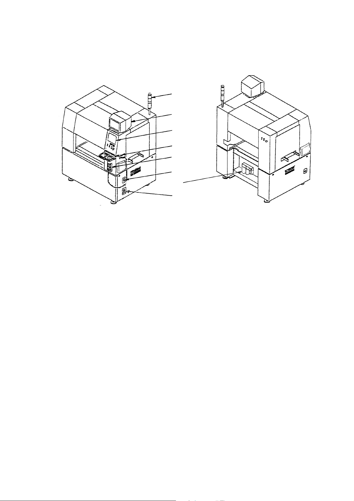
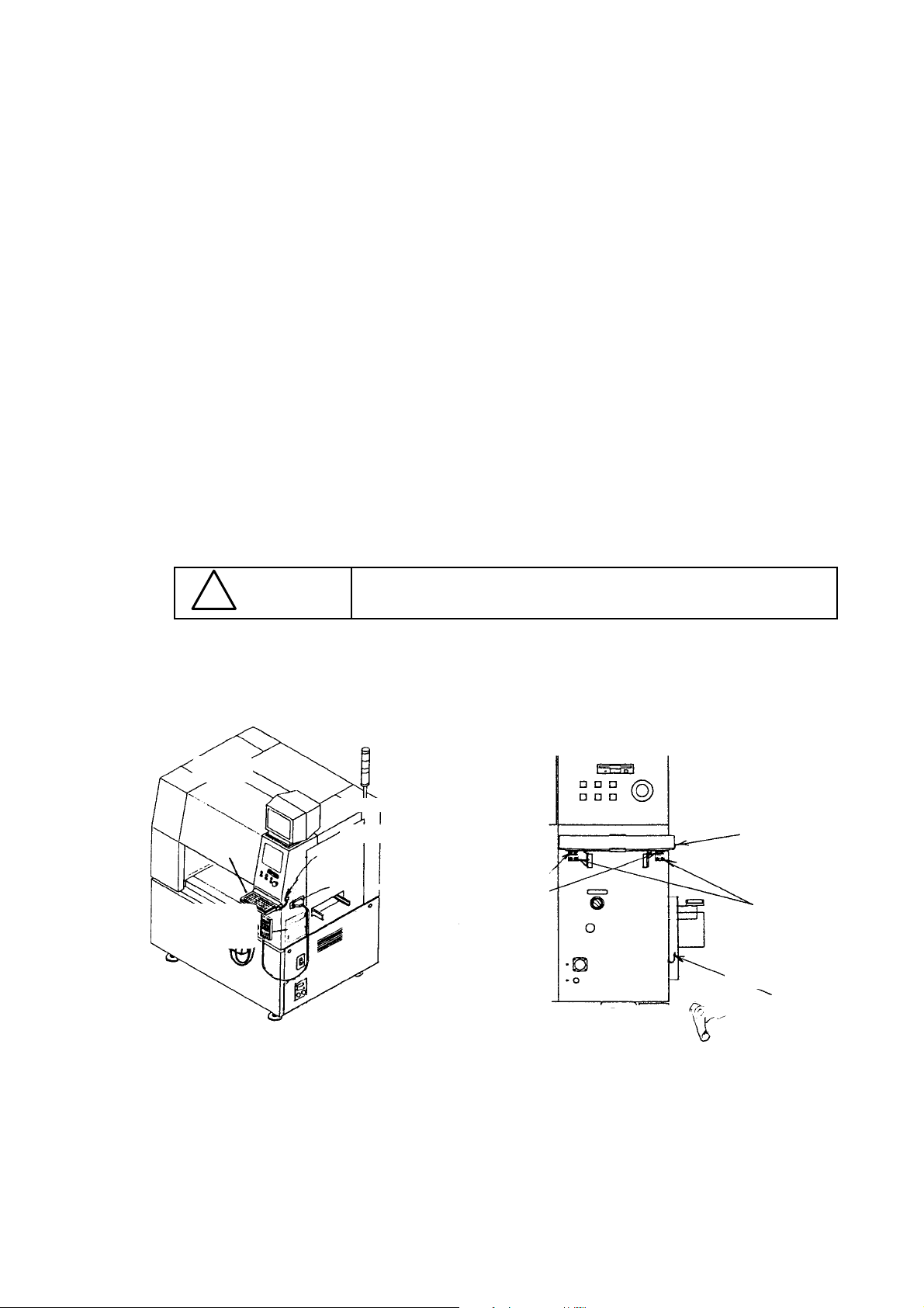
1. Basic Configuration and Name of Each Part
t
w
e
y
r
q
u
i
Figure 1.1 Figure 1.2
1. Breaker 5. Signal light
2. Vision monitor 6. Keyboard
3. Liquid crystal display 7. Filter regulator
4. HOD (Handheld Operating Device) unit 8. Interface panel
- 1 -
Page 5
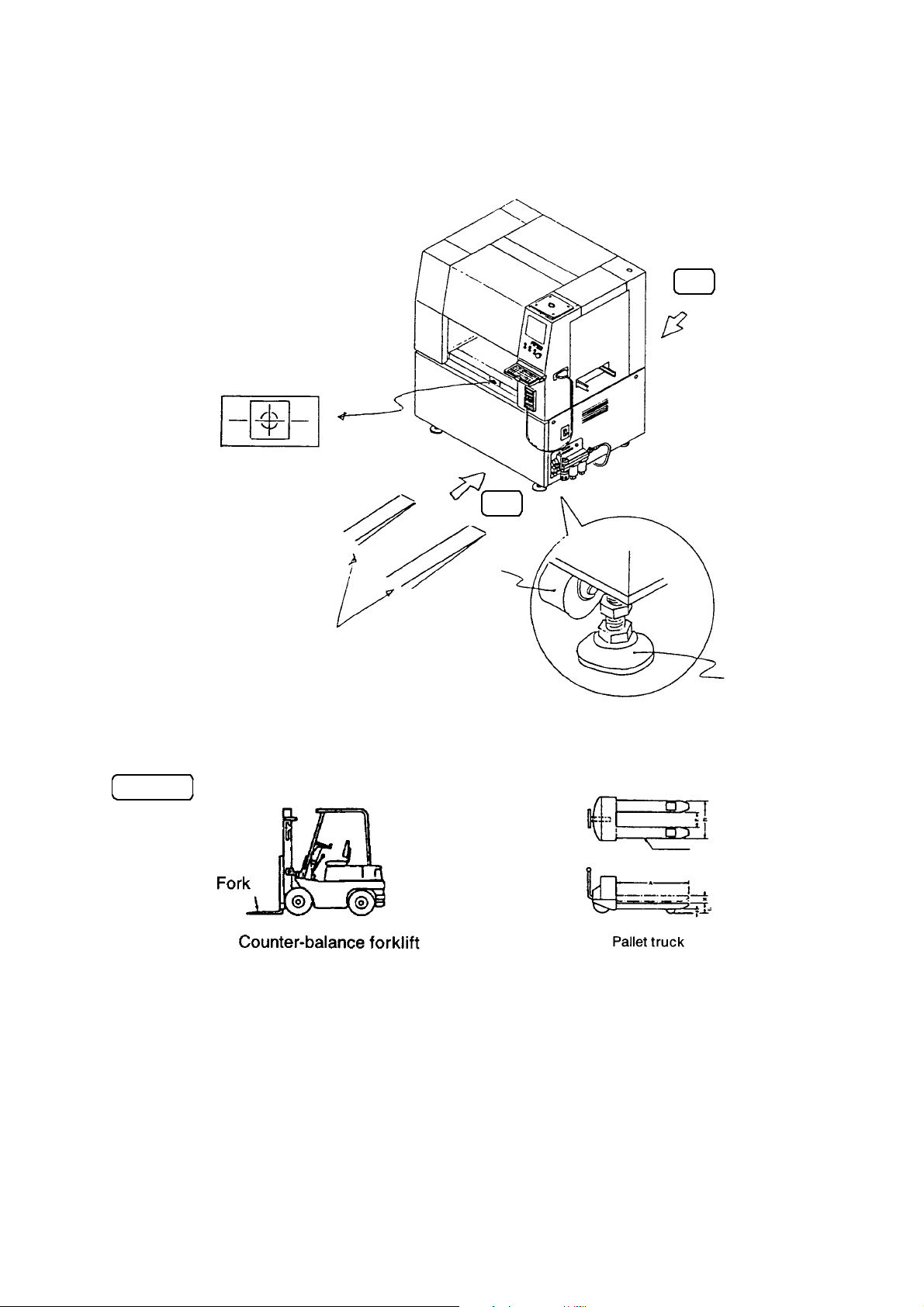
2 . How to Install the Main Unit
Center mark
Rear
Front
Example
o
Fork of the forklift
(finger of the pallet truck)
!0
Figure 2.1
Counter-balance forklift
Figure 2.2 Figure 2.3
- 2 -
Page 6

(1) Lift the adjuster !0 to bring the casters o into contact with the floor before
installing or moving the main unit.
(2) When using a forklift to mov e the main unit, be sure to put the fork under the
bottom of the main unit from the front side, then lift and mov e it after the fork
protrudes enough from the rear of the main unit. (Follow this instruction also
when you use a pallet truck to move the machine.)
(1) Make sure of the center mark when moving the machine with a
CAUTION
!
forklift (pallet truck).
(2) Do not use a forklift (pallet truck) to move the machine with a vision
monitor w and signal light t attached.
- 3 -
Page 7
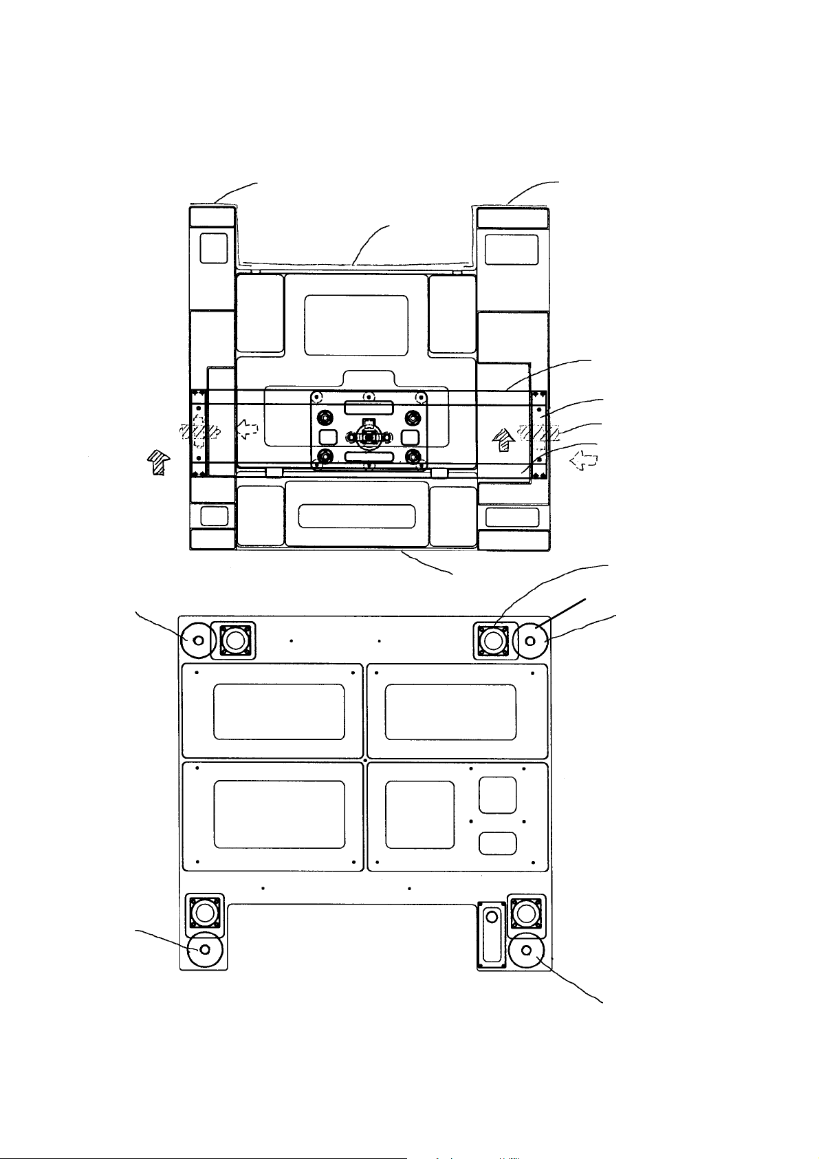
3 . Adjusting the Transport Height and Leveling the Machine
e
Cover RBL
Cover RBC
Cover FB
Figure 3.1 (Viewing from the top of unit.)
Cover RBR
Base bar R
Base bar B
Level vial
Base bar F
Caster
r
Adjuster
w
Figure 3.2 (Viewing from the bottom of unit.)
- 4 -
q
Page 8

(1) Adjustment procedure
1) Detach the cover FB, cover RBC, cover RBR and cover RBL.
2) Loosen three hexagonal screws of adjuster. (Make sure that the adjuster moves
freely.)
3) Lift the adjuster in the order of q, e , w , r, q ,... as shown in Figure 3.2. You can
easily lift the main unit.
4) Leveling the main unit in the front and rear directions.
Put the level vial on the point indicated as a dotted line, and adjust the adjusters q
and w or e and r to set the level vial within – 1 division of the scale specified on
the supplied level setting table.
5) Leveling the main unit in the left and right directions.
Put the level vial on the point indicated as an actual line, adjust the adjusters q and
r or w and e to set the level vial within – 1 division of the scale specified on the
supplied level setting table.
6) Repeat Steps 4) and 5) to set the level vial on the base bar B within – division of
the scale specified on the supplied level setting table.
7) Lock the adjust nut.
Make sure that the level vial is set within – 1 di vision of the scale specified on the
supplied level setting table while being in lock.
8) Tighten three hexagonal screws of adjuster
.
- 5 -
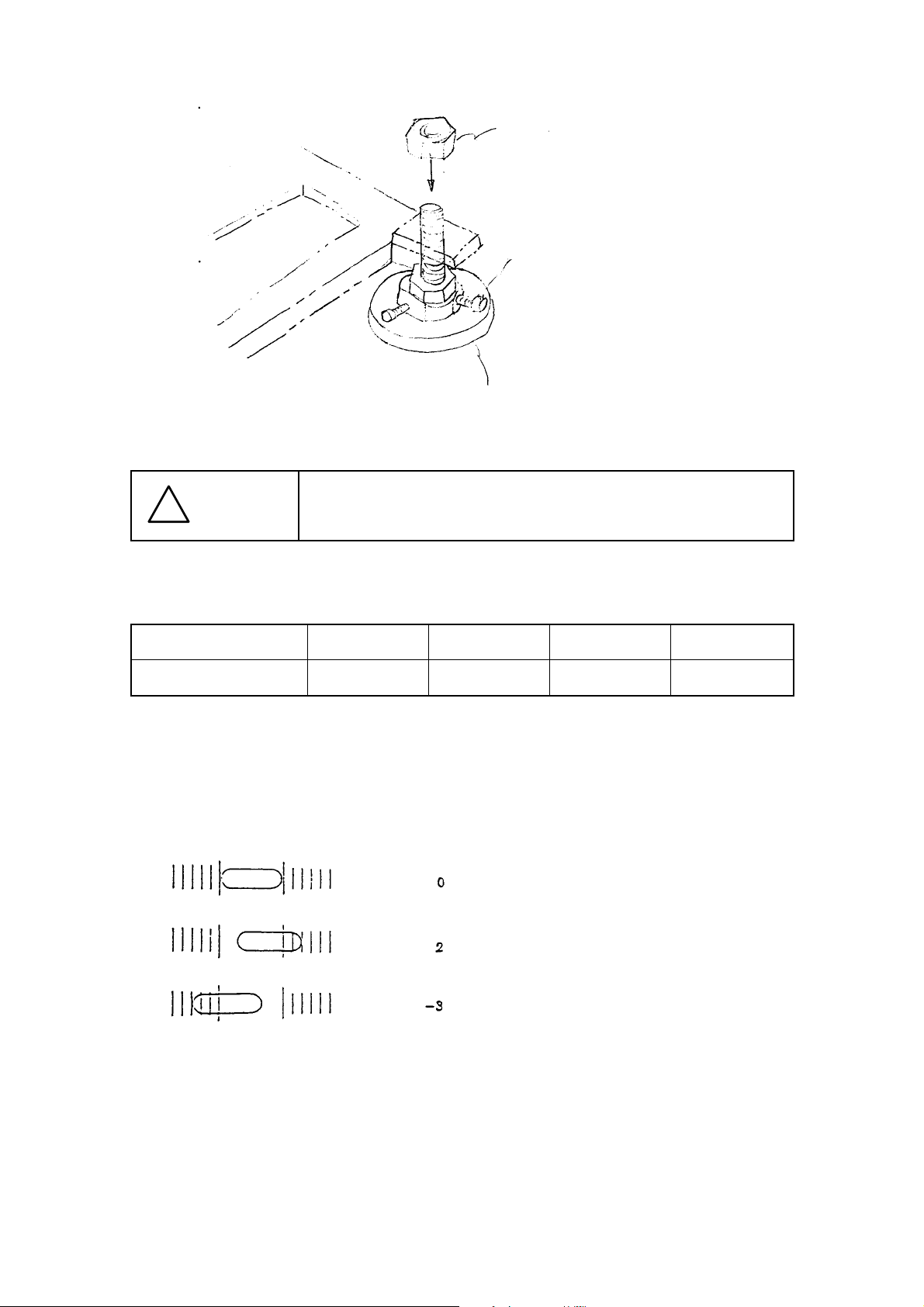
Page 9
Base room inside
CAUTION
!
Adjust nut
Hexagonal screw
Adjust foot
The right scales of the level vial are + (plus) and the left ones are ( m inus ) w hen vi ew ed fr om t he a r r ow m a r k of the l ev el v i a l a s si gnm ent
figure.
Level setting table
Setting position A B C D
Setting value
Note: In case of the level vial (0.05/1 scale)
The scales (setting value) of the level vial
- 6 -
Page 10
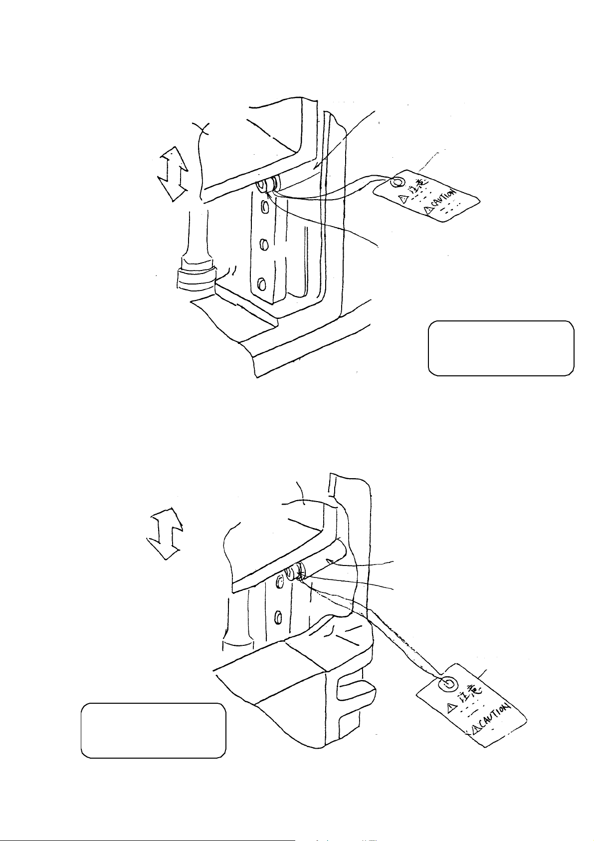
4. Demounting the Head Unit Fixing Parts
Z-axis slide bracket
KE-750
Spacer
HX00334000C
Set-up caution tag
Shammy cap
SL6042542TN
❋ As for the model KE-750,
remove the fixing parts
to detach three heads.
(1) Remove the shammy cap screw to detach the spacer.
(2) Make sure that the Z-axis slide bracket smoothly moves vertically.
Z-axis slide bracket
Spacer
HX00334000C
Shammy cap
SL6042542TN
Set-up caution tag
❋ As for the model KE-760,
remove the fixing parts
to detach two heads.
KE-760
- 7 -
Page 11
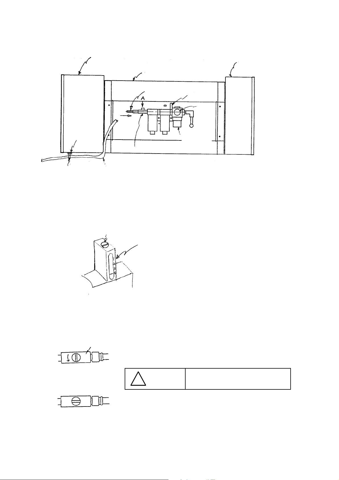
5. Connecting the Air Tubes
Fixing base
Tie-up band
Cover RBR
Fixing base
connect
Cover RBC
Piping at factory side
Hand valve
Pressure
switch
Pressure
gauge
Pressure
adjustment
knob
Cover RBL
1) Connect the air tube (¿.12), piped at the factory side, to the hand valve.
2) Adjust the pressure adjustment knob to 5 kgf/cm
3) Make sure that the pressure switch is set to 4 kgf/cm
2
.
2
.
(Use the (-) screw driver to adjust the pressure switch.)
4) Fix the air tub e, p ip ed at the factory s ide, at the fixing b as e w ith t he tie-up b and.
(It should not interfere in the replacement table.)
A view direction drawing
Hand valve
(a) Close
Pressure switch (Pressure detection cable assembly)
Be sure to use dried ai r through the
CAUTION
!
drier to supply compressed air.
(b) Open
- 8 -
Page 12
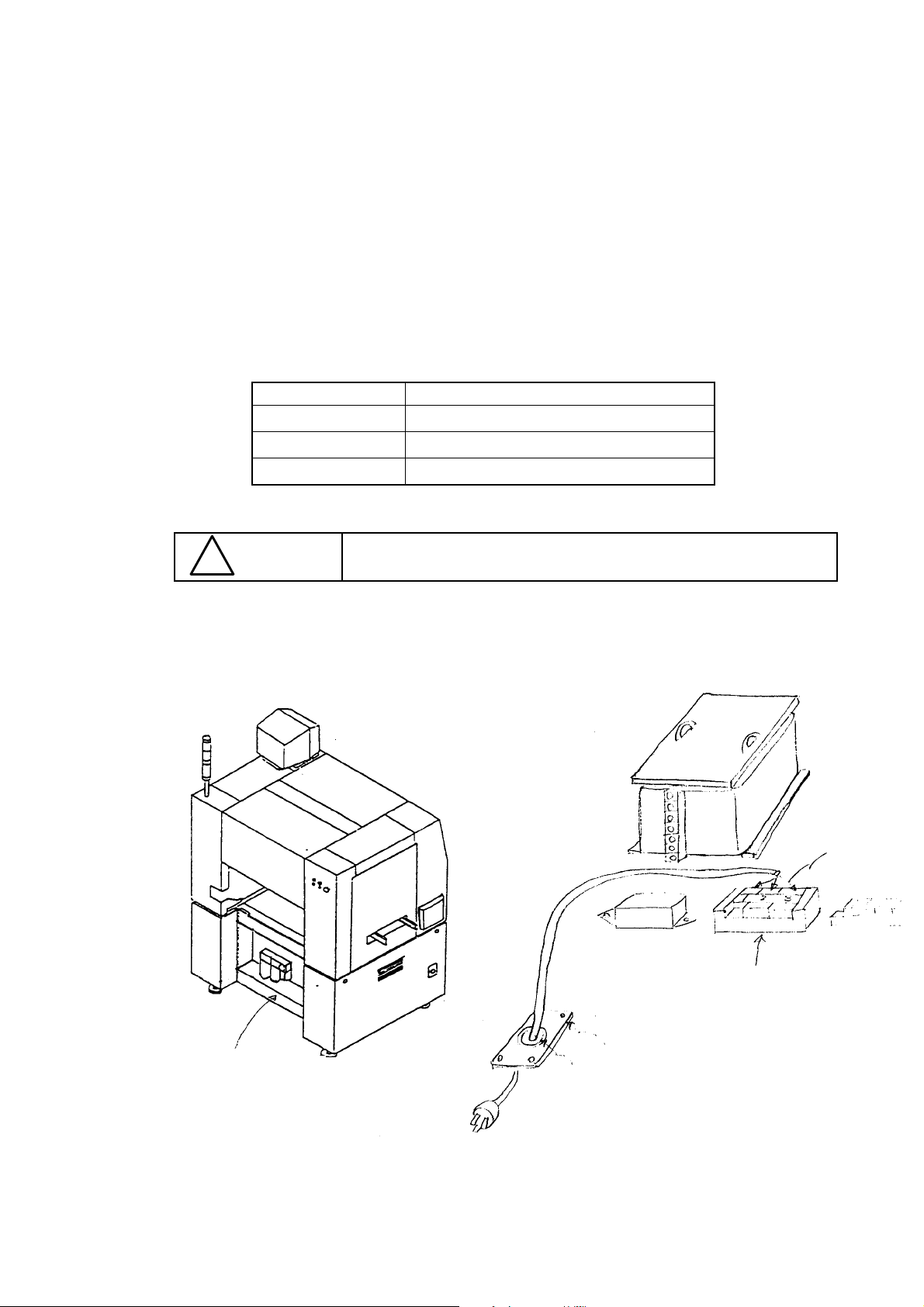
6. Connecting the Power Code
(1) Remove the cover RBC located on the rear of the main unit.
(2) Insert the power code inside the main unit via a groummet with a film after passing it
through a mouth guard as shown in Figure 6.2.
2-1 Be sure to install the insulation cover on the terminal plate after connecting the
power code to the terminal plate.
(3) Connect each terminal of the power code to the terminal plate of the power unit.
3-1 You can connect the black line to the No. 2 plate and the white line to the No. 1
plate because the alternate current is supplied.
Table 6.1
Color of the line Number of the terminal plate
Black (white 1
White (black) 2
Green 3
CAUTION
!
Make sure that the plugs of the power supply side has been
assembled before connecting the power code to the main unit.
Ground
Terminal plate
Cover RBC
Figure 6.1 Main unit (rear side)
Figure 6.2
Mouth guard
Grommet with a film
- 9 -
Page 13
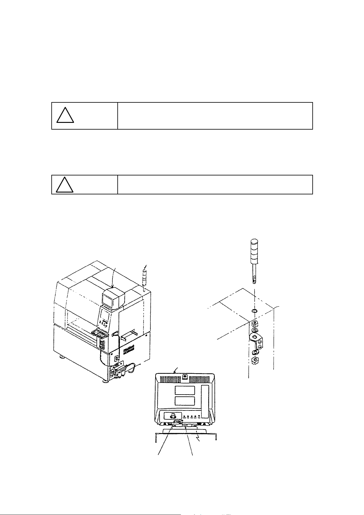
7. Attaching Other Supplied Parts
(1) Signal Light
a) Insert the signal light through the upper hole of the cover RUR.
b) Locate the supplied nuts and washers as indicated in Figure 7.2, then fix them on
the bracket. Connect the connector to the bracket.
After installing the signal light, adjust its height so that the distance
CAUTION
!
(2) Vision Monitor
a) Insert the power code of the vision monitor from the hole in the middle of the monitor
base to the main unit, then fix the top of the vision monitor on the monitor base.
from the floor to the upper surface of the signal light can be 2,000 mm
(2,050 mm if installing the machine abroad).
CAUTION
!
b ) Pull out the image monitor cab le from the rear of the monitor top , then connect it to
the VIDEO IN jack.
c) Connect the power code connector to the power relay cable at the rear side of the
panel computer.
Make sure that the protruded part of the monitor top is hooked over
the knob of the monitor base.
Vision
monitor
Signal light
Cover RUR
Figure 7.1
Image monitor cable
- 10 -
Monitor base
Knob
Figure 7.2
Figure 7.3
Page 14
(3) Keyboard Bracket Assembly
a) Fix the keyboard connecting plate of the keyboard bracket ass embl y on the main
unit with four stopper screws as shown in Figure 7.5.
b) Connect the keyboard cable to the keyboard connector located in the hole on the
right side of the cover FUR.
(4) HOD (Handheld Operating Device)
a) Connect the HOD cable to the HOD connector located on the right side of the
main unit.
(5) Hand knob
a) Hook the hand knob over the handle hook located on the front right of the main
unit.
(6 ) Feeder relay cable
Connect the feeder relay cable and air tube from the connector bracket to the
connectors on the main unit cover (Perform this operation for the front and rear
sides).
! CAUTION
Keyboard
bracket
assembly
Connector
bracket
The connector bracket is already fixed on the replacement table
(optional).
Keyboard connector
HOD connector
Keyboard
connecting
Hand knob
Keyboard
bracket
assemblyplate
Stopper
screws (four)
(SM0040601SC)
Handle hook
Figure 7.4
Figure 7.5
- 11 -
Page 15
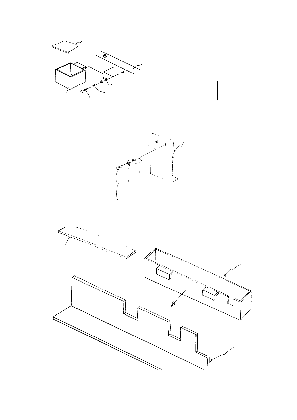
x
Chip box
E2801721000
Figure 7.1
Chip cushion
E2802721000
Washer (small circle) WP03020500SC
Washer (large) WP0330516SC
Hexagonal screw SM6030602TN
✴ Hook the U-shaped groove of the chip bo
over the washer (small circle).
Rail plate FR/FL
2 x 2 positions
Chip box stay
Washer (large)
WP0330516SC
Hexagonal screw
SM6030602TN
Washer (small circle)
WP03020500SC
Figure 7.2
Chip box L
E2803723000
Figure 7.3
ATC support angle
E3424725000
- 12 -
Page 16

(7) Chip Box Assembly
<Front reference>
a) Hook the U-shaped groove over the washer fixed on the rail plate FR and the chip
b ox s tay with a hexagonal screw as s how n in Figure 7.1. Hook the chip b ox L
over the ATC support angle as shown in Figure 7.3.
<Far end reference>
a) Hook the U-shaped groove over the washer fixed on the rail plate FL and the chip
b ox s tay with a hex agonal screw as s how n in Figure 7.2 Hook the chip b ox L
over the ATC support angle as shown in Figure 7.3.
- 13 -
Page 17
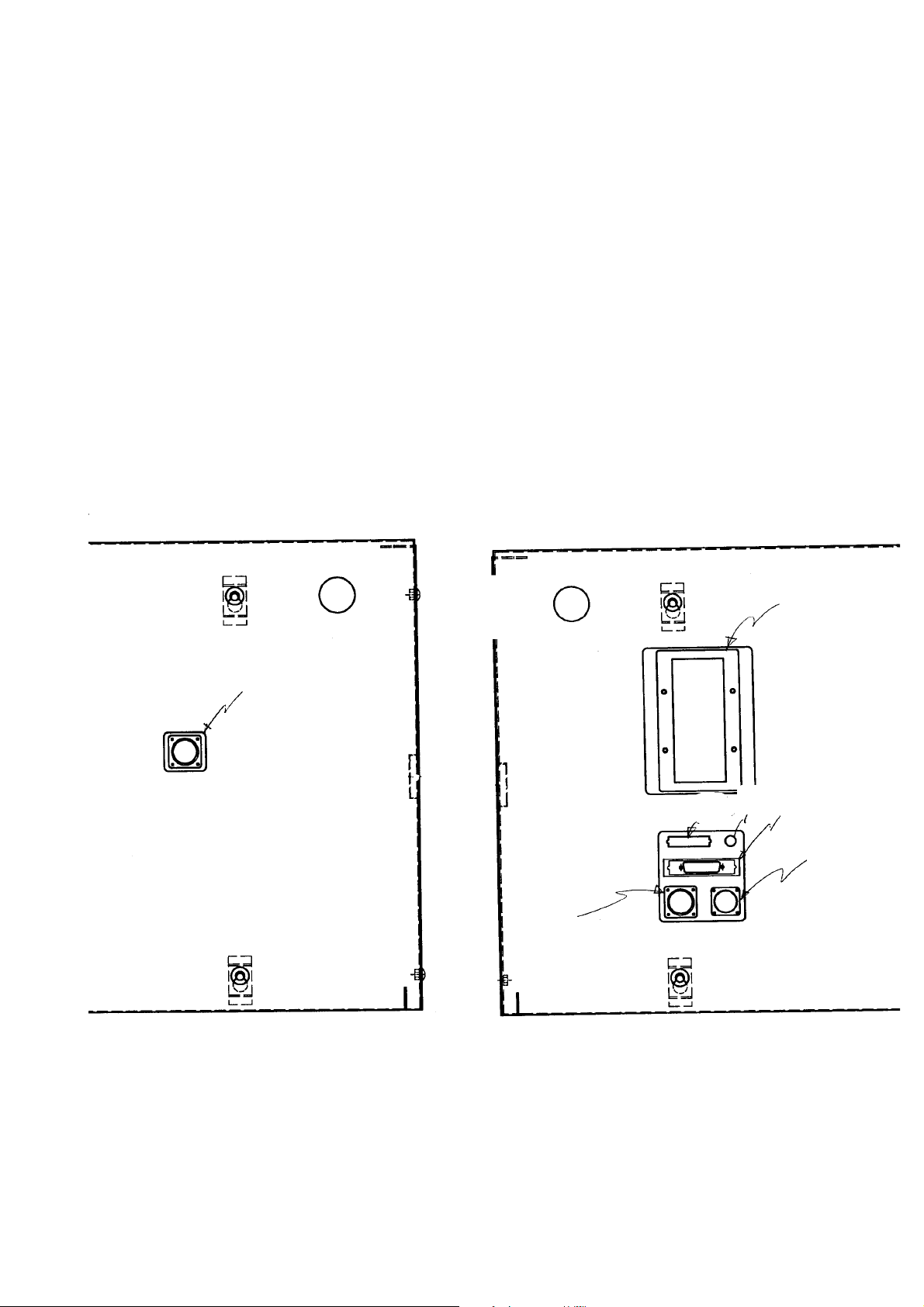
8 . Interface with External Equipment
1) q is the READY OUT (IN) connector (14-pin) to be connected to external equipment
when you use the machine as inline. The pin assignment is different depending on
the board transport direction; left to right or right to left as indi cated in Table 1-4-1
and Table 1-4-2 .
2) w is the connector (50-pin) for the signal from/to an optional matrix tray changer.
3) e is the power connector (10-pin) (AC 100 V) for an optional matrix tray changer.
4) r is the printer connector (D-Sub, 25-pin) and conforms to the Centronics standard.
q
q
w
Light
Breaker
r
e
Figure 8.1 Front left side of the main unit Figure8.2 Front right side of the main unit
- 14 -
Page 18
Signal (left to right) Signal (right to left) Connctor type
1 READY OUT+ READY IN+
2 READY OUT- READY IN- (GND)
3 BOARD AVAILABLE 1 BOARD AVAILABLE 3
4 BOARD AVAILABLE 2 BOARD AVAILABLE 4
5NC NC
6NC NC
7NC NC
8NC NC
9NC NC
10 NC NC
11 NC NC
12 NC NC
13 NC NC
14 NC NC
Table 8.1 Connectors on the front left side of the main unit
AMP
206043-1
(Connectors of the
cable are 206044-1)
Signal (left to right) Signal (right to left) Connctor type
1 READY IN+ READY OUT+
2 READY IN- (GND) READY OUT-
3 BOARD AVAILABLE 3 BOARD AVAILABLE 1
4 BOARD AVAILABLE 4 BOARD AVAILABLE 2
5NC NC
6NC NC
7NC NC
8NC NC
9NC NC
10 NC NC
11 NC NC
12 NC NC
13 NC NC
14 NC NC
Table 8.2 Connectors on the front right side of the main unit
AMP
206043-1
(Connectors of the
cable are 206044-1)
- 15 -
Page 19

The interface circuit diagram of the READY OUT (IN) and BOARD AVAILABLE connectors is
indicated in Figure 8.3. These connectors conform to the SMEMA standard.
READY OUT 1
READY OUT 2
+24 V
15 KΩ
BOARD AVAILABLE 2
BOARD AVAILABLE 1
+24 V
15 KΩ
READY IN
Figure8.3
GND
BOARD AVAILABLE 3
BOARD AVAILABLE 4
- 16 -
Page 20

Signal Connector type
1 -Strobe
2D0
3D1
4D2
5D3
6D4
7D5
8D6
9D7
10 -ACK
11 BUSY D-SUB 25-pin, FEMALE
12 PE
13 SLCT
14 -AUTO FEED XT
15 -ERROR
16 -INIT
17 -SLCT IN
18 GND
19 GND
20 GND
21 GND
22 GND
23 GND
24 GND
25 GND
Table 8.3 Pin assignment of the printer connector
- 17 -
Page 21

9. Attaching the Matrix Tray Changer (MTC)
Figure 9.1
54
Placer MTC entrance to be inserted
Placer MTC entrance to be inserted
Figure 9.2
Adjuster
rubber
- 18 -
Shuttle fitting bracket
Adjuster retainer
Adjuster spacer
Page 22

(1) Rear placement set-up (TR4NE)
S et the MT C so t hat the gap is within 54 mm as shown in Figure 9.1. Attach the
adjuster rubber and adjuster spacer at the position where the adjuster retainer can be
attached at the adjuster part, and tighten the lock nut with adjusting its height with the
adjuster. Then fix it with the adjuster retainer.
Be sure to set the MTC so that the gap between the machine unit and
CAUTION
!
the M T C uni t ( TR 4N E) is 54 m m or l ess ; other w i s e, the head m a y not
move to the pick position.
- 19 -
Page 23

Figure 9.3
* (104 or less)
Conveyor fixing screw
(long hole:6 portions)
Figure 9.4
Adjust screw
- 20 -
Page 24

(2) Horizontal placement set-up (related drawing) TR3NE
Set the MTC so that the gap is within 104 mm as shown in Figure 9.3 after detaching
the shuttle. Adjust its height with the adjust screw. Attach the shuttle after set-up.
Be sure to set the MTC so that the gap between the machine unit and the MTC
CAUTION
!
unit (TR3NE) is 104 mm or less; otherwise, the head may not move to the pick
position.
- 21 -
Page 25

Cover SBR
SMEMA
q
Breaker
Light
Printer connector
Interface panel
w
q MTC signal connector
w MTC power connector
MTC air supply opening
e
Cover RBR
Figure 9.3
Cover RBC
Filter regulator
Cover RBL
Figure 9.4
- 22 -
Page 26

Connect the MTC power connector and signal connector to the interface panel on the front
right side of the main unit as shown in Figure 9.3, then connect the air tube to the MTC air
joint on the rear side of the main unit.
CAUTION
!
Use two cables and an air tube supplied with the MTC.
- 23 -
Page 27

10. Checking the Machine Before Tuning on the Power
Check to see if:
q The machine is leveled.
w The height of the board transport rail satisfies the specifications.
e The lock nut of the adjuster is fixed.
r Air is supplied normally.
t The power code is connected properly, and its voltage is appropriate.
y The supplied parts are attached properly.
u The machine is connected to external equipment properly.
i Each unit operates smoothly. Check the following parts manually:
1) Y-axis: Hold both edges of the X axis with both hands and move the X axis from
the front to the rear and vice versa smoothly.
2) X-axis: Hold the head bracket, and mov e it from left to right and v ice versa
smoothly.
3) Head: Move the Z-axis and -axis with your hands smoothly.
- 24 -
Page 28

11. Adjusting the Height of the Replacement Table (Optional)
Perform the height adjustment for the replacement table after leveling the main unit.
Do not fall down the replacement table sideways while changing the
CAUTION
!
(1) Adjusting the Caster Plate Fixing Position
You can set the height of the replacement table in two step s depending on the
manner the caster plate is fixed.
Adjust the height according to that of the board transport track.
caster plate fixing position; otherwise, the trolley handle may be
damaged.
Caster plate
Upper
Trolley frame
Fixing screwplate
Figure 11.1
Lower
Figure 11.2
Board transport height Caster plate fixing position
880 to 900 mm Upper (See the upper figure.)
900 to 920 mm Lower (See the lower figure.)
Add 50 mm if the machine is for ZEVA.
The cas ter plate is already fix ed on the low er p osition ( indicated in the Figure 11.2)
when the replacement table is installed.
- 25 -
Page 29

CAUTION
!
When the gap between the bank location pin B and the bottom of the bank
support is less than 7mm as shown in Figure 11.3, fix the caster plate at the
upper position.
Bank support
7 mm
Bank location pin B
Figure 11.3
- 26 -
Page 30

Adding the trolley spacer (E2738721000) (For height adjustment)
Adjust the height of the replacement table with the trolley spacer as shown in Figure 11.4 if an
inconvenience occurs due to a slanting floor or a low replacement table.
Height adjustment tap (M6)
Trolley spacer
Fixing screw
Trolley
E2738721000
Caster plate
Figure 11.4
1. Loosen the fixing screws.
2. Ins ert the M6 screw into the height adjust ment tap , then turn the M6 screw until the
space between the caster plate and the trolley is made.
3. Insert the required pieces of the trolley spacer into the space.
4. Remove the adjustment screw, then tighten the fixing screw.
CAUTION
!
When the caster plate is fixed at the upper
position, insert the trolley spacer into the
space between the trolley and the fixing
screw, and then fix them as shown in
Figure 11.5.
Trolley
Caster plate
Fixing screw
- 27 -
Trolley spacer
Figure 11.5
Page 31

(2) Adjusting the Bank Stopper Fixing Position
S et the b ank stop p er in up p er, middle, or low er p os ition according to the b oard
transport height.
Bank stopper
Roller guide
Figure 11.6
Board transport height Bank stopper fixing position
894 to 900 Lower
914 to 920 mm
887 to 893 Middle
907 to 913 mm
880 to 886 Upper
900 to 906 mm
(Add 50 mm when the machine is for ZEVA.)
The position of the bank stopper above is just an example. Attach the
CAUTION
!
bank stopper where the trolley stopper plate touches more of the
bank stopper. The left fixing position may be different from the right
fixing position depending on the floor where the machine is installed.
Bank stopper
Trolley stopper plate
Figure 11.7
- 28 -
Page 32

MAIN UNIT UNPACKING GUIDE
(Main Unit Packing Guide)
Page 33

Table of Contents
1. Head Unit .................................................................................................................1
2. X-Y Unit....................................................................................................................3
3. Board Transport Unit................................................................................................5
4. ATC (Auto Tool Changer) Unit ................................................................................8
5. VCS (Vision Centering System) Unit ......................................................................9
6. CAL Block..............................................................................................................10
7. HOD (Handled Operating Device) Bo x ................................................................11
8. Vision Monitor.........................................................................................................11
9. Signal Light.............................................................................................................12
10. Keyboard Bracket Assembly.................................................................................13
11. Feeder Relay Cable of the Connector Bracket......................................................14
12. Safety Cover .........................................................................................................15
13. Filter Regulator (Air Assembly)...............................................................................16
14. Replacement Table (Optional).............................................................................. 17
List of Supplied Parts to Be Packed ......................................................................20
15. Hand disk...............................................................................................................24
Page 34

-
1. Head Unit
1-1. Fixing the Z-Axis
Z-axis slide bracket
Spacer HX00334000C
Set-up caution tag
Shammy cap
SL6042542TN
(1) Attach the spacer as
indicated in Figure 1.1 to
prevent the Z-axis slide
b racket from moving up
or down.
(2) Make sure that the head
unit is stable after
attaching the spacer
even though y ou move
it in the direction
indicated with the arrow
mark.
Z-axis slide bracket
Figure 1.1
Spacer HX00334000C
Shammy cap
SL6042542TN
CAUTION
!
Attach the set-up caution
tag onto the shammy cap for
each head respectively.
Set-up caution tag
Figure 1.2
- 1
Page 35

-
1-2. Head Main Unit (KE-750, KE-760)
Drier
Figure 1.3
1. Put the drier into the bottom of the OCC as indicated in Figure 1.3.
2. Wrap the bott om of the head w ith a p iece of anticorrosiv e pap er, then p as te a tap e
over the anticorrosive paper.
3. Wrap the head completely with the air cap, then fix them with an adhesive tape.
Anticorrosive
paper
- 2
Page 36

-
2. X-Y Unit
(1) Fixing the Y-axis Rail (Fixing the X-axis Frame Assembly)
q Move the whole X-axis frame completely to the front of the machine, then push it
against the stopper rubber located on the front side.
w Fix the safety cover stoppers (E1348700000) on two taps (right and left) located
on the linear guide of the Y-axis frame with the M5 x 20 screws from the rear side.
Adjust the eccentricity of the stopper to push the Y-axis frame against the rubber
on the front, then fix it.
e Attach the set-up caution tag onto the fixing part.
M5 x 20 screw
(SM6052002TN)
Tap E1348700000
X-axis Unit
Set-up caution tag
Figure 2.1
- 3
Page 37

-
2) Fixing the X-axis Rail (Fixing the Head Bracket)
q Move the head bracket (whole head unit) on the X-axis to the left side of the unit.
w Move the head b racket (whole head unit) comp letely to the left s ide to pus h it
against the rubber stopper. Then, fix the X-axis stopper at two M3 taps located
on the b ottom of the X- axis frame w ith the s hammy cap S L6030842TN from the
bottom.
e Attach the set-up caution tag onto the X-axis stopper.
2 x ( M3 x l8) + (M3 Spring washer)
(SL6030842TN = Shammy cap)
Figure 2.2
X-axis stopper
(E5001715000)
- 4
Page 38

-
3. Board Transport Unit
(1) Supplied Parts to Be Packed
Pack the following three items together with other supplied parts into the
E5353700000 packing carton box (See theList of Supplied Parts to Be Packed).
Remove them from the board transport unit to pack them.
(Note that the hand knob is to be used to change the board transport rail width.)
Supplied parts:
E20217150A0 Back up pin M assembly 8
E2206700000 Hand knob 1
E2801725000 Chip box assembly 2
Screw shaft
U plate
Chip box
assembly (two)
Hand knob
Back up pin M assembly (eight)
Figure3.1
- 5
Page 39

-
(2) How to Pack
a. Packing the Center part
1) Roll up the air cap which is to be crashed easil y when the board width is set
to the minimum value (30 mm), then put it into the center part.
2) Adjust the board transport width to the minimum value (30 mm), and paste
filament tapes approximately in the middle of the screw shaft and the guide
shaft (two positions) (see Figures 1-1 and 2-1).
300
Rail plate M
Air cap
Filament tapes (two positions)
Rail plate F
Move these plates until the board
transport width becomes the
minimum value (30 mm).
Figure2.1
CAUTION
!
b. Right And Left Edges
1) Put air cap which can be crashed easily into the protruded parts from the main
unit.
2) Wrap the air cap around the protruded parts as indicated in Figure 2-2.
Make sure that the rail plate (black part) receives no load. If the rail
plate is deformed, the machine cannot operate normally.
*Note that the air cap should n o t
touch any sensor.
Filament tapes
q
CAUTION
!
w
Figure3.2
Make sure that the rail plate (black part) receives no load. If the rail
plate is deformed, the machine cannot operate.
e
- 6
Page 40

-
c. BU plate
Fix the BU plate with filament tapes (four positions).
ilament tapes (four positions)
Fix the BU plate so that it
can be kept stable.
BU plate
Figure3.3
- 7
Page 41

-
4. ATC(Auto Tool Changer) Unit
p
q Fix the nozzle on the ATC unit.
w Align the hole of the ATC b as e w ith that of the s lide plate, then p ut t he tie-up b elt
through these holes. Tighten the tie-up belt. Make sure that the slide plate is fixed
and all nozzle cannot be removed.
e Cover the nozzle with air cap so that it cannot move, then paste adhesive tapes over
the air cap to fix them.
Nozzle
Air ca
Slide plate
ATC base
Figure4.1
Tie-up belt
Hole
- 8
Page 42

-
5. VCS (Vision Centering System)Unit
q Cover the whole unit completely with air cap.
w Paste an adhesive tape on the air cap at the bottom of the light base.
Air cap
Light base
Figure5.1
Adhesive
tape
- 9
Page 43

-
6 . CAL Block
q Cover the upper part of the CA block with air cap to protect the upper surface of the
CAL plate, then fix the air cap with an adhesive tape.
Air cap
Tape
CAL plate
Figure 6.1
w Put the CAL p iece A and the C AL p iece B into viny l sacks s ep arately. W rap
these vinyl sacks with air cap, then pack them in the carton box where the other
supplied parts are packed.
Vinyl sack
Air cap
Figure 6.2
❇ The CAL piece B is supplied with only the KE740 or FM740 model.
- 10
Page 44

-
7. HOD (Handheld Operating Device) Box
See the HOD box packing assembly (E53027000A0) to pack the HOD box.
8. Vision Monitor
Repack only the monitor in the carton box which the manufacturer specified.
q Do not disassemble the stand part from the mounter main unit.
w Put air cap in the carton box when there is any gap in the
CAUTION
!
carton box after repacking the monitor.
e Paste an adhesive tape whose width is 50 mm over the
carton box after repacking the monitor to close the carton
box.
Figure 8.1
Monitor
Stand part
Carton
Figure 8.2
- 11
Page 45

-
9. Signal Light
Rep ack the patrol light cab le ass emb ly (E94417150A0) in the carton box w hich the
manufacturer specified.
Carton
CAUTION
!
Pack the nuts and washers (supplied) in the same carton box also.
Patrol light
cable assembly
Figure 9.1
- 12
Page 46

-
10. Keyboard Bracket Assembly
(1) Disconnect the keyboard connection cable from the main unit.
(2) Remove four stopper screws fixing the keyboard attachment plate, then the keyboard
bracket assembly from the main unit.
(3) Pus h dow n the keyboard s tands L and R ins ide, w rap the w hole keyb oard b racket
assembly with air cap completely, and pack it in the same carton box where the other
supplied parts are packed.
Keyboard connection cable
Keyboard
attachment plate
Figure 10.1 Figure 10.2
- 13
Keyboard stand L
Stopper
screws
Keyboard stand R
Page 47

-
11. Feeder Relay Cable of the Connector Bracket (Supplied)
Fix the feeder relay cable and air tube on the connector bracket with a filament tape.
CAUTION
!
Fix the air tube so that it cannot be damaged at all.
Feeder relay cable
Filament
tape
Figure 11.1
Connector
bracket
Cover FB
The front of the connector bracket is fixed on the cover FB , and the rear is fix ed on the
cover RBC.
CAUTION
!
The connector bracket is already fixed on the replacement table
(optional).
- 14
Page 48

-
12. Safety Cover
Fix the safety cover with a filament tape so that it cannot be opened.
Safety cover
Filament tape
Figure 12.1
- 15
Page 49

-
13. Filter Regulator (Air Assembly)
1. Remove the air tube, piped at the factory side.
2. Do not remove this unit if exporting the machine abroad because this model differs from
the former models, such as KE-710/720 and KE-730/740.
CAUTION
!
Cover RBR
Turn off the air of the main unit before following the instructions
above.
Cover RBL
Cover RBC
Piping at factory side
remove
Figure 13.1
- 16
Page 50

-
14. Replacement Table (Optional)
(1) Fixing the Feeder Bank and the Floor Trolley
Fix the feeder bank and the side pole of the floor trolley with the P.P band.
P.P band
Figure 14.1
Feeder band
Floor trolley
(2) Fixing the Trolley Handle (Right and Left)
Fix the slider and the trolley handle by wrapping them with a filament tape.
Hook the tie-up belt over the stopper screw to keep the trolley handle stable.
Stopper screw
Tie-up belt
Filament tape
Slider
Trolley handle
Figure 14.2
- 17
Page 51

-
(3) Fixing the Feeder Relay Cable
Fix the feeder relay cable and the air tub e on the connector b racket with a filament
tape.
Feeder relay
cable
Connector
Filament tape
Figure 14.3
bracket
!
CAUTION
Take care not to damage the air tube at all.
- 18
Page 52

-
(4) Wrap the whole unit with air cap completely.
Air cap
Trolley
Floor
Feeder bank
trolley
Connec t or
brac ket
Feeder
relay
cable
Figure 14.4
- 19
Page 53

-
KE-750 List of the Supplied Parts to Be Packed
Pack the following supplied parts in the E5010715000 carton box.
Part No . Part Name Quantity
E94507000A0 Power cable assembly 1
E9690715000 Light 1
E53027000A0 HOD Box packing assembly 1
E6953861B00 Content label 2
MDFRX1001L0 New deflexed oil No. 1 1
J1067000000 Oil feeder 1
B91212200A0 Oil feeder 1
MGREAS400G0 Grease 1
J106600000B Hexagonal wrench 2 mm 1
J106600000C Hexagonal wrench 2.5 mm 1
J106600000D Hexagonal wrench 3 mm 1
J106600000E Hexagonal wrench 4 mm 1
J1080000000 Ball screwdriver 1
MAI17002000 Cross-headed screw driver (No.1) 1
E0120K750A0 Operating Instructions (KE750 Japanese) 1
E5001715000 X-axis stopper 1
SL603842TN 5001 Shammy Cap 2
NM6030001SC 5001 hexagonal nut 2
!
1)
!
!
!
E1348700000 Safety cover stopper 2
SM6052002TN 1348 hexagonal-hole-headed screw 2
E5010715000 Supplied carton box 1
E28017250A0 Chip box assembly 2
E5002721000 Packing box for keyboard 3
Op erating In structions ( K E750 Engl i sh) f o r a fo r e i gn count r y ( ZEVA ) 1
E20217150A0 Back up pin M assembly 8
E2206700000 Hand knob 1
E13417210A0 Keyboard bracket assembly 1
E36217210A0 CAL piece assembly (730) 1
E29007250A0 Air set (ø4, ø6, ø10 excluding any tube) 1
2)
E9613721000 Hard disk 1
)
5
E1014725000 Adjust nut 30 4
6)
HX003630000 Tie-up belt 1
- 20
Page 54

-
CAUTION
abels
!
1) Select parts to be packed depending on th e user.
2) This part is fixed on the main unit for Japan. Do not pack it in the carton
box. (Remove it from the main unit and pack it in the carton box if the
machine is to be exported abroad.)
3) Put air cap so that there cannot be any gap inside the carton box.
4) Paste the content labels on the outside of the carton box (two
positions)
PARTS NO. KE750 or FP750
PARTS NAME ACCESSORY
L
5) Remove the adjust nut 30 from the main unit, then pack it into the
supplied carton box.
6) The tie-up belt is used to fix the air tube which is piped at the factory
side.
* Refer to page 8 in the Set-up Guide.
- 21
Page 55

-
KE-760 List of the Supplied Parts to Be Packed
Pack the following supplied parts in the E5010715000 carton box.
Part No . Part Name Quantity
E94507000A0 Power cable assembly 1
E9690715000 Light 1
E53027000A0 HOD Box packing assembly 1
E6953861B00 Content label 2
MDFRX1001L0 New deflexed oil No. 1 1
J1067000000 Oil feeder 1
B91212200A0 Oil feeder 1
MGREAS400G0 Grease 1
J106600000B Hexagonal wrench 2 mm 1
J106600000C Hexagonal wrench 2.5 mm 1
J106600000D Hexagonal wrench 3 mm 1
J106600000E Hexagonal wrench 4 mm 1
J1080000000 Ball screwdriver
MAI17001000 Cross-headed screw driver (No.1) 1
E0120K760A0 Operating Instructions (KE760 Japanese) 1
E5001715000 X-axis stopper 1
SL603842TN 5001 Shammy Cap 2
NM6030001SC 5001 hexagonal nut 2
E1348700000 Safety cover stopper 2
!
1)
!
!
!
SM6052002TN 1348 hexagonal-hole-headed screw 2
E5010715000 Supplied carton box 1
E28017250A0 Chip box assembly 2
E28037250A0 Chip box L assembly 3
E5002721000 Packing box for keyboard 3
Opera ting Instr uctions ( KE760 Engli sh) for a f or ei gn country ( ZEVA) 1
E20217150A0 Back up pin Assembly 8
E2206700000 Hand knob 1
E13417210A0 Keyboard bracket assembly 1
E36417210A0 CAL piece set (740) 1
E29007150A0 Air set (ø4, ø6, ø10 excluding any tube) 1
2)
E9613721000 Hard disk 1
)
5
E1014725000 Adjust nut 30 4
6)
HX003630000 Tie-up belt 1
- 22
Page 56

-
CAUTION
abels
!
1) Select parts to be packed depending on the user.
2) This part is fixed on the main unit for Japan. Do not pack it in the carton
box. (Remove it from the main unit and pack it in the carton box if the
machine is to be exported abroad.)
3) Put air cap so that there cannot be any gap inside the carton box.
4) Paste the content labels on the outside of the carton box (two
positions)
PARTS NO. KE760 or FP760
PARTS NAME ACCESSORY
L
5) Remove the adjust nut 30 from the main unit, then pack it into the
supplied carton box.
6) The tie-up belt is used to fix the air tube which is piped at the factory
side.
Refer to page 8 in the Set-up Guide.
- 23
Page 57

-
15. Hard Disk
p
The hard disk should be detached and transported with packed separately.
q Remove the hard disk from the main unit.
B e s ure to s p ecify the model numb er of the machine from w hich the hard dis k is
removed.
w Wrap the hard disk with an anti-static air cap.
Double
40 cm or more
20 cm or more
e Fix the air cap with a cellophane adhesive tape so as not to spread.
r Place the hard disk into the supplied box.
1. Take care that the hard disk is stable in the supplied box.
CAUTION
!
2. Place the supplied screws in the sack, then fix the sack on the air ca
wrapping the hard disk with a cellophane adhesive tape.
- 24
Page 58

Revision Date
00 1997. 07
● Specifications are subject to be changed without notice.
– 1 –
Page 59

ELECTRONIC ASSEMBLY &
TEST SYSTEM DIVISION
8-2-1, KOKURYO-CHO, CHOFU-CITY, TOKYO 182, JAPAN
PHONE: 03-3480-3330 FAX: 03-3488-1971
TELEX: 03-242-4343 JUKI J
Sales agent
 Loading...