

Page 1

Lockstitch machine with a long arm and a thread trimmer
J-350QVP
INSTRUCTION MANUAL
EN
Attention :
Congratulations on your purchase of a JUKI sewing machine.
Please be sure to read this Instruction Manual before operating the sewing machine
to ensure safe operation. Please be sure to keep the Instruction Manual so that you
can read it whenever necessary.
JUKI website: http://www.juki.com
Page 2

"IMPORTANT SAFETY INSTRUCTIONS"
When using an electrical appliance, basic safety precautions should always be followed, including the
following: Read all instructions before using this sewing machine.
"DANGER
1. An appliance should never be left unattended when plugged in.
2. Always unplug this appliance from the electric outlet immediately after using and before cleaning.
____
"WARNING
1. Do not allow this appliance to be used as a toy. Close attention is necessary when this appliance
is used by or near children. This appliance can be used by children aged from 8 years and above
and persons with reduced physical, sensory or mental capabilities or lack of experience and
knowledge if they have been given supervision or instruction concerning use of the appliance
in a safe way and understand the hazards involved. Children shall not play with the appliance.
Cleaning and user maintenance shall not be made by children without supervision.
2. Use this appliance only for its intended use as described in this manual. Use only attachments
recommended by the manufacturer as contained in this manual.
3. Never operate this appliance if it has a damaged cord or plug, if it is not working properly, if it has
been dropped or damaged, or dropped into water. Return the appliance to the nearest authorized
dealer or service center for examination, repair, electrical or mechanical adjustment.
4. Never operate the appliance with any air openings blocked. Keep ventilation openings of the sewing machine and foot controller free from the accumulation of lint, dust and loose cloth.
5. Keep ngers away from all moving parts. Special care is required around the sewing machine
needle.
6. Always use the proper throat plate. The wrong plate can cause the needle to break.
7. Do not use bent needles.
8. Do not pull or push fabric while stitching. It may deect the needle causing it to break.
9. Switch the sewing machine off ("O") when making any adjustments in the needle area, such as
threading needle, changing needle, threading bobbin, or changing presser foot and the like.
10. Always unplug sewing machine from the electrical outlet when removing covers, lubricating, or
when making any other user servicing adjustments mentioned in the instruction manual.
11. Never drop or insert any object into any opening.
12. Do not use outdoors.
13. Do not operate where aerosol (spray) products are being used or where oxygen is being administered.
14. To disconnect, turn all controls to the off ("0") position, then remove plug from outlet.
15. Do not unplug by pulling on cord. To unplug, grasp the plug, not the cord.
16. Turn OFF the power switch before insertion/removal of any cords and any plugs.
17. Basically, the machine should be disconnected from the electricity supply when not in use.
18. If the power cord of this appliance is damaged, it must be replaced with a special cord byyour
nearest authorized dealer or service center.
To reduce the risk of electric shock:
____
To reduce the risk of burns, re, electric shock, or injury to persons:
"
"
"SAVE THESE INSTRUCTIONS"
This sewing machine is intended for household use only.
Use the stitch regulator made by the Grace Company.
Stitch regulator can be used on the following machine model-number.
Sewing machine model number Stitch regulator model number
J-350QVP Sure Stitch for JUKI J-350
In order to use your machine safely, be sure to read the Instruction Manual for the Sure Stitch for
JUKI J-350QVP provided by Grace Company for how to install the machine on the frame, how to connect the stitch regulator and how to operate the machine.
– 1 –
Page 3
Congratulations on your purchase of a JUKI sewing machine.
Please be sure to read safety precautions in "To use the sewing machine safely" in the Instruction
Manual before use to fully understand the functions and operating procedures of the sewing machine so as to use the sewing machine for a long time.
After you have read the Instruction Manual, please be sure to keep it together with the warranty so
that you can read it whenever necessary.
To use the sewing machine safely
Marks and pictographs included in the Instruction Manual and shown on the sewing machine are
used so as to ensure safe operation of the sewing machine and to prevent possible risk of injury to
the user and other people.
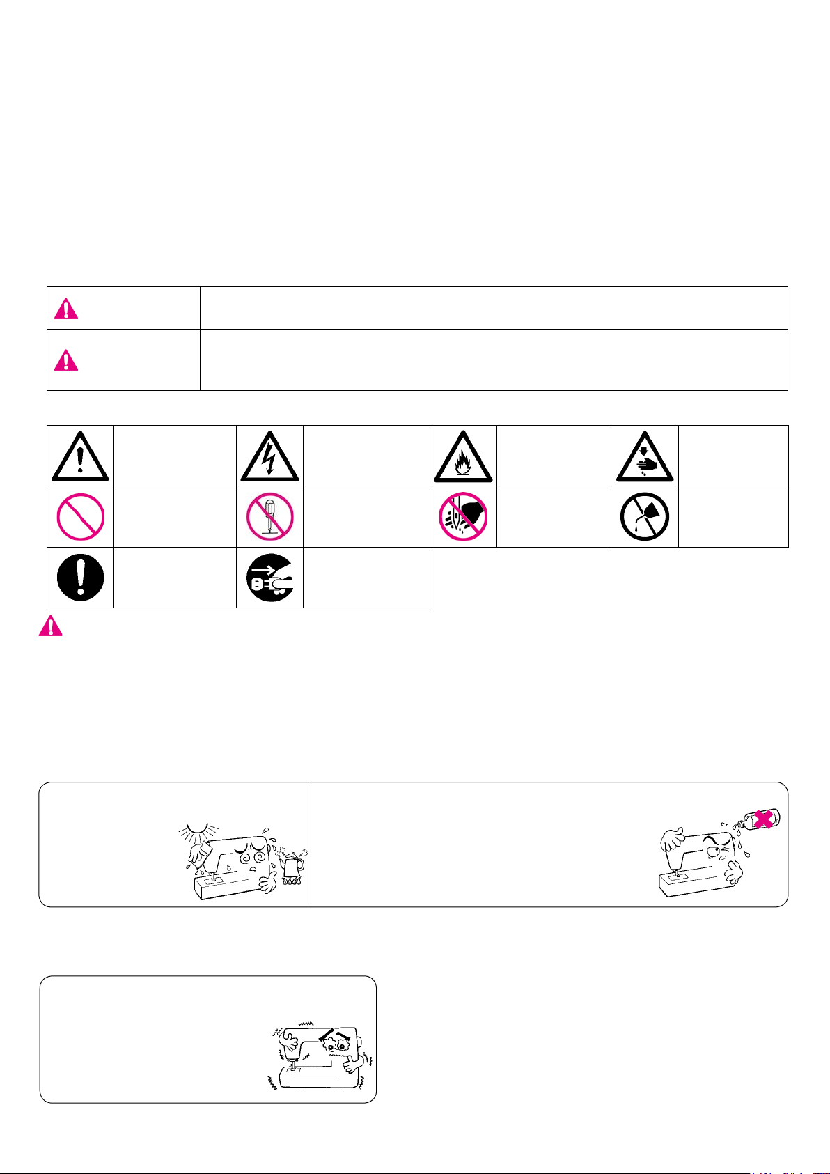
Warning marks are used for different purposes as described below.
WARNING
ATTENTION
Pictographs mean the following:
Danger
warning which
is not specied
Prohibited
matter which is
not specied
Generally
required
behavior
WARNING
For the combination of the material and the thread and needle, in particular, refer to the explanation
table in "Replacement of the needle".
If the needle or thread does not match the material used such as in the case that an extra heavyweight material (e.g., denim) is sewn with a thin needle (#11 or higher), the needle can break resulting in an unexpected personal injury.
Indicates that there is a possible risk of death or serious injury if this
mark is ignored and the sewing machine is used in a wrong manner.
Indicates the operation, etc. which can cause a possible risk of personal
injury and/or physical damage if this mark is ignored and the sewing machine is used in a wrong manner.
There is a risk
of electrical
shock
Disassembly/
alteration is
prohibited
Disconnect the
power plug
There is a risk
of re
Do not place
ngers under
the needle
There is a
risk of injury
to hands, etc.
Do not pour
oil, etc.
Other precautions
●
● Do not put the sewing machine
under the direct
sunlight or
in ahumid
place.
Be aware that the following state can take place since the sewing machine incorporates semi-conductor electronic parts and precise electronic circuits.
● Be sure to use the sewing machine in
the temperature range
from 5ºC to 40ºC.
If the temperature is exces-
sively low, the machine can
fail to operate normally.
Do not wipe the sewing machine with solvent such as thinner.
When the sewing machine is soiled, put
a small quantity of neutral detergent on a
piece of soft cloth and carefully wipe off the
sewing machine with it.
* The operating temperature of the sewing machine
is between 5ºC and 40ºC. Do not use the sewing
machine under the direct sunlight, near the burning
things such as a stove and candle, or in a humid
place. By so doing, the temperature in the interior
portion of the sewing machine can rise or the coating of the power cord can melt, causing re or electrical shock.
– 2 –
Page 4

HOW TO CARRY THE SEWING MACHINE
A
CAUTION
How to take out the sewing machine
CAUTION
If you pull up the sewing machine by holding presser regulating screw
section A, the sewing machine can break.
In addition, be aware that the presser regulating screw can break if a
physical impact is given to it.
Pull out the sewing machine from the cutout of styrene foam by holding
the main body of the arm.
Turn OFF the power switch. Always must be disconnected plug from socket-outlet.
How to hold the sewing machine
CAUTION
1. Never hold the handwheel since it rotates.
2. Always must be handle the sewing machine with two persons or
more since the sewing machine weighs 26 kg or more.
3. Do not hold the sewing machine by placing hands near the needle
bar and the presser bar to avoid the risk of injury.
Carry the sewing machine while holding the machine arm with two per-
sons as shown in the gure.
– 3 –
Page 5
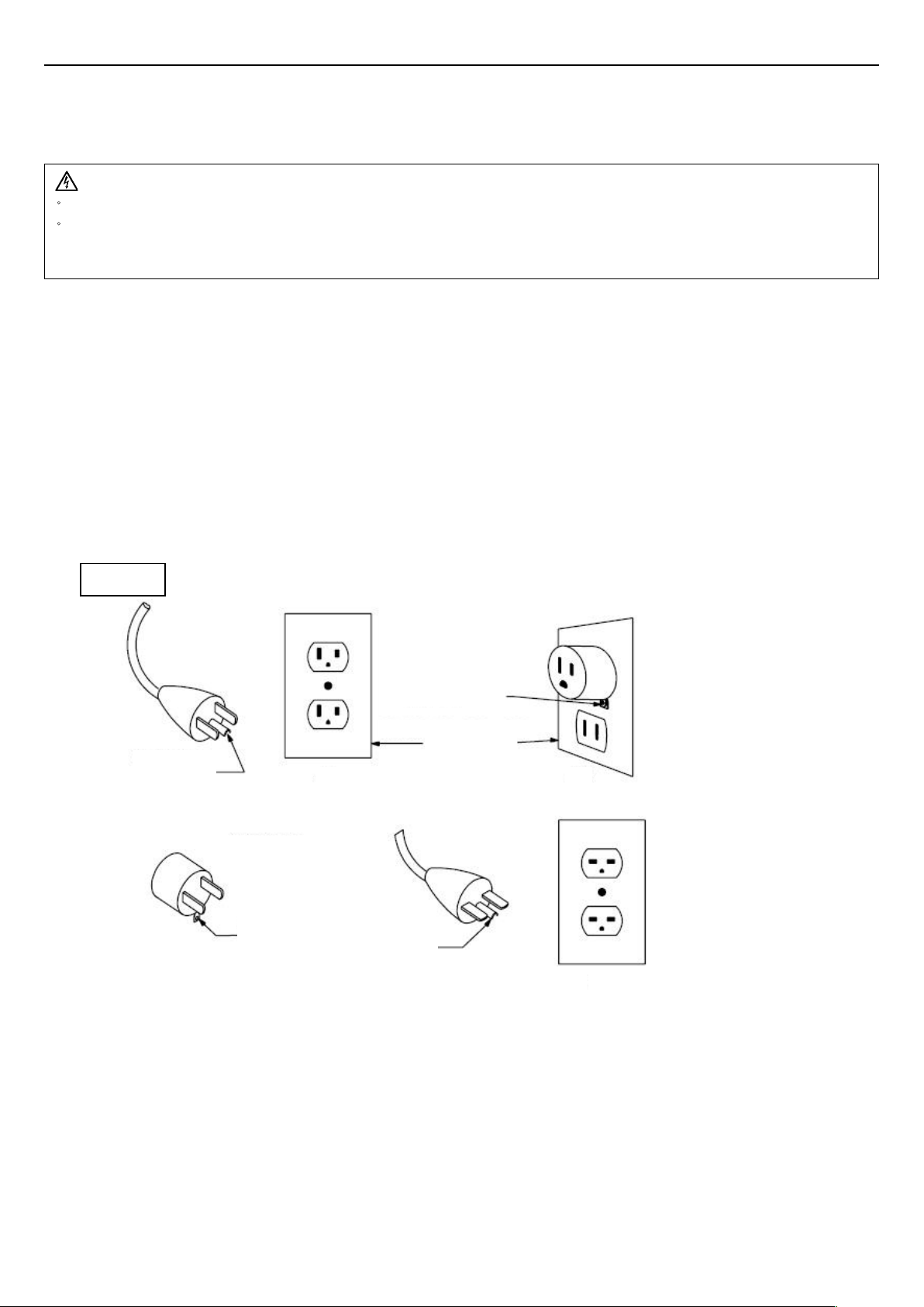
GROUNDING INSTRUCTIONS
This product must be grounded. In the event of malfunction or breakdown, grounding provides a path of least resistance
for electric current to reduce the risk of electric shock. This product is equipped with a cord having an equipment-grounding conductor and a grounding plug. The plug must be plugged into an appropriate outlet that is properly installed and
grounded in accordance with all local codes and ordinances.
DANGER
Improper connection of the equipment-grounding conductor can result in a risk of electric shock.
・
The conductor with insulation having an outer surface that is green with or without yellow stripes is the equipment-
・
grounding conductor. If repair or replacement of the cord or plug is necessary, do not connect the equipment-grounding
conductor to a live terminal.
Check with a qualied electrician or serviceman if the grounding instructions are not completely understood, or if in doubt
as to whether the product is properly grounded.
Do not modify the plug provided with the product. if it will not t the outlet, have a proper outlet installed by a qualied
electrician.
This product is for use on a nominal 120 V circuit, and has a grounding plug that looks like the plug illustrated in sketch
A
in Figure 1. A temporary adaptor, which looks like the adaptor illustrated in sketches B and C, may be used to connect
this plug to a 2-pole receptacle as shown in sketch B if a properly grounded outlet is not available. The temporary adaptor
should be used only until a properly grounded outlet can be installed by a qualied electrician. The green colored rigid ear,
lug, and the like, extending from the adaptor must be connected to a permanent ground such as a properly grounded outlet box cover. Whenever the adaptor is used, it must be held in place by the metal screw.
Figure 1
Grounding
pin
(C)
Adapter
Grounding
means
(A)
Metal
screw
Cover of
grounded
outlet box
(B)
Grounding
pin
(D)
– 4 –
Page 6

CONTENTS
IMPORTANT SAFETY INSTRUCTIONS ...................................................1-2
HOW TO CARRY THE SEWING MACHINE ...............................................3
GROUNDING INSTRUCTIONS ...................................................................4
Specications ...............................................................................................6
Accessories ..................................................................................................6
Principal Parts ..............................................................................................7
Name and Function of each component..................................................8-12
Winding the bobbin ................................................................................13-16
Attaching the needle ................................................................................... 16
Threading the machine ............................................................................... 17
Adjusting the thread tension ..................................................................18-19
Presser foot lifting lever .............................................................................. 19
Setup and operation ..............................................................................20-27
Maintenance ............................................................................................... 28
Maintenance and lubrication..................................................................28-29
Troubles and Corrective Measures ............................................................30
– 5 –
Page 7
Specications
Description Specication
Sewing speed Max. 2,200 sti/min
Needle bar stroke 35 mm
Lift of presser foot 4.5 mm
Needle GB 134R
Lubricating oil New Defrix Oil No.1
Dimensions of sewing machine 22.2W x 46.0H x 73.0L (cm)
Weight of sewing machine 26 kg
Rated power supply / Power consumption AC100V-AC240V/1.2A-0.8A, 50/60Hz
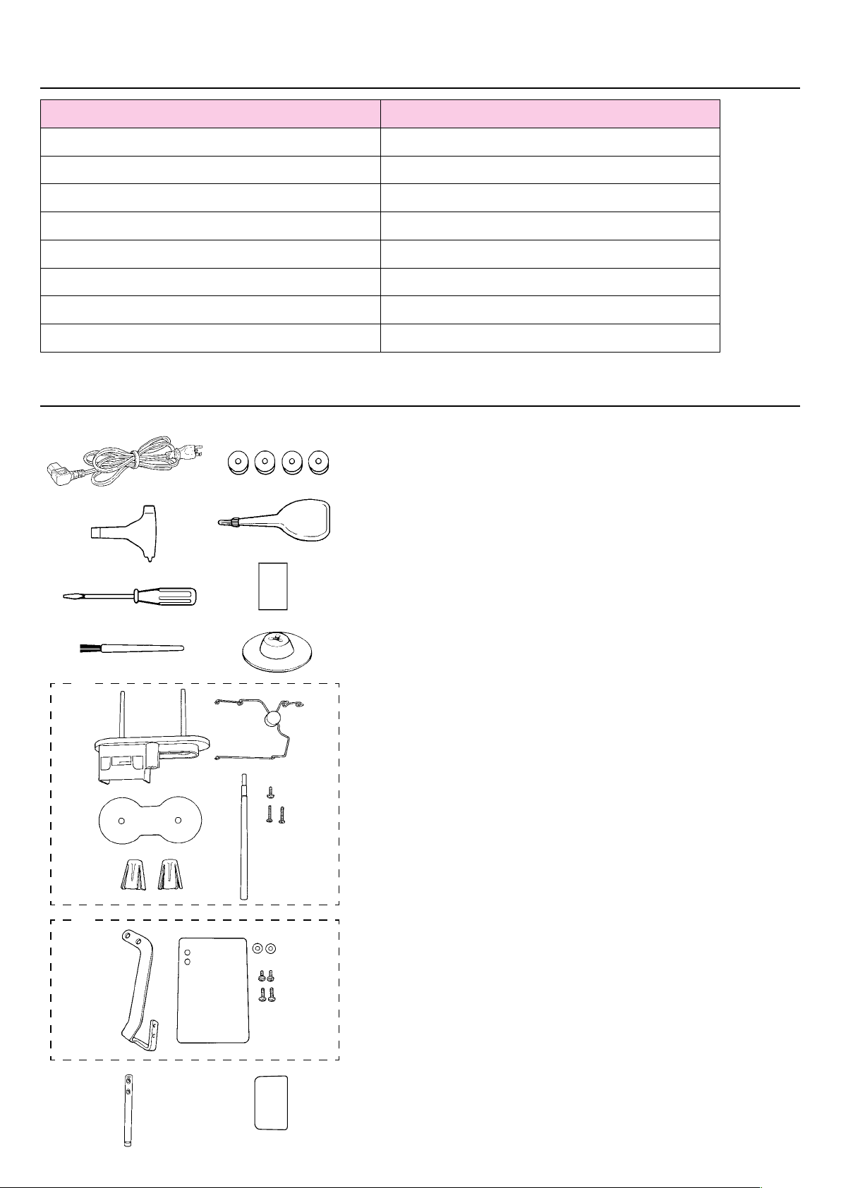
Accessories
1
2
5
6
7
3
4
8
9
1. Power cord
2. Exclusive screwdriver
3. Screwdriver (medium)
4. Cleaning brush
5. Bobbins (4pcs.)
6. Oilcan
7. Needles (GB 134R #18)
8. Spool cap
9. Thread stand components
(Spool holder disk, thread stand thread guide, bobbin winderspool
holder disk, bobbin winder seat, bobbin winder side anchors(two
pieces), setscrew (large), setscrews (small) (two pieces))
10. Eye protection cover components
(Safety plate, safety plate mounting plate, washers (two
pieces),setscrews (large) (two pieces), setscrews (small) (two
pieces))
11. Thread guide pin
12. Blind seal (Spare)
10
11 12
– 6 –
Page 8
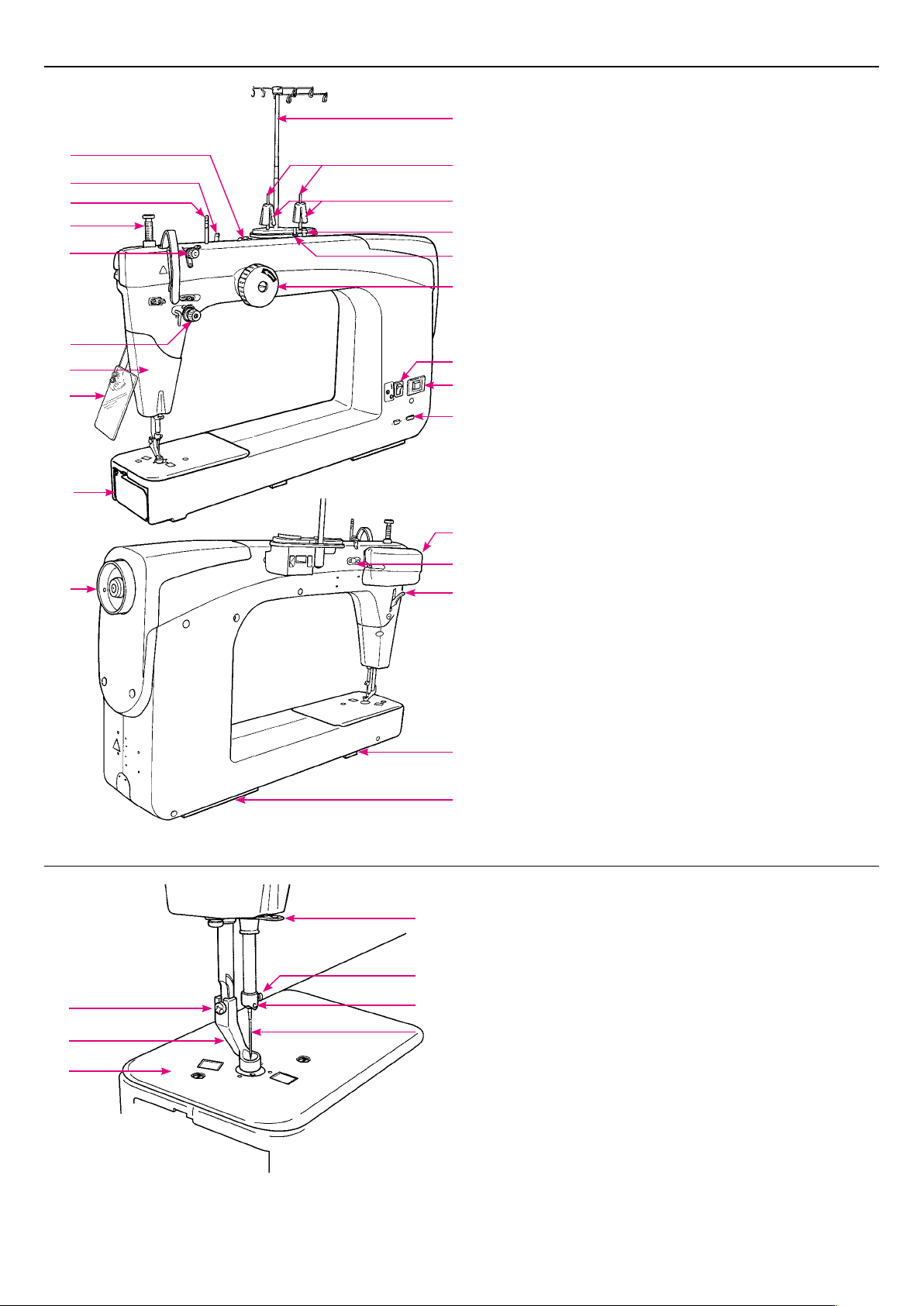
Principal Parts
1
2
15
3
17
4
5
16
22
18
7
8
9
10
11
6
12
13
20
19
21
14
1. Thread trimmer retaining plate
2. Thread guide base
3. Presser foot pressure regulator
4. Thread tension dial
5. Lamp (built-in type)
6. Hand pulley
7. Bobbin winder
8. Spool holder disk
9. Bobbin winder side anchor
10. Bobbin presser
11. Bobbin winding shaft
12. Power switch
13. Inlet of electric power cord
14. Presser foot lifting lever
15. Thread guide pin
16. Eye protection cover
17. Tension controller No. 1
18. Hand wheel
19. Presser regulator cover
20. Stitch regulator connection connector
21. Panel junction cable connection connector
22. Hook cover
23. Connecting plate (large)
24. Connecting plate (small)
24
23
1. Screw in the presser foot
2. Presser foot
7
3. Throat plate
4. Needle clamp
4
5. Needle bar thread hook
6. Needle
1
2
5
7. Needle bar thread guide
6
3
– 7 –
Page 9
Name and Function of each component
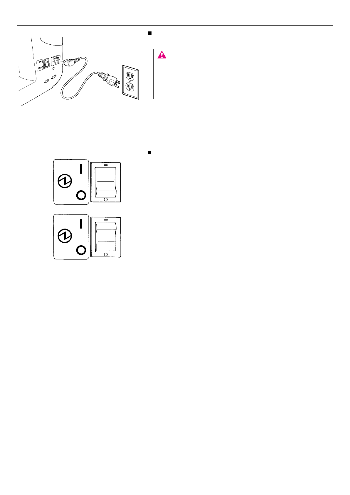
Power cord
Insert the electric power cord plug into the corresponding inlet.
CAUTION
Turn OFF the power switch before insertion/removal of any cords
and any plugs.
Perform these following steps before you are not using your sewing
machine.
1. Turn OFF the power switch.
2. Remove the power plug from the wall outlet.
Power switch
Turn ON the machine, set the power switch to ”I”.
Turn OFF the machine, set the power switch to ”O”.
ON
OFF
– 8 –
Page 10
❻
❺
❹
❸
❷
❶
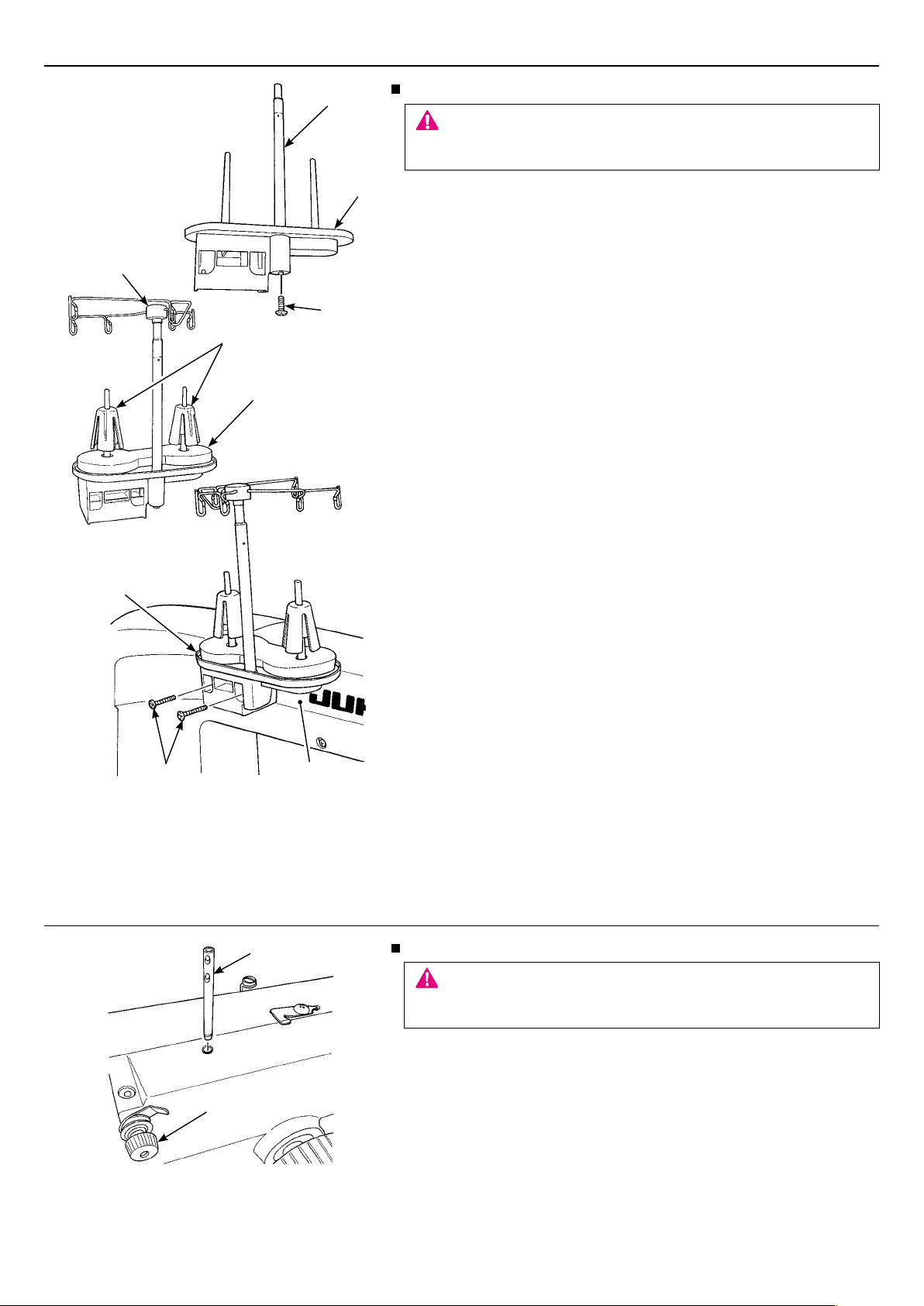
Installing the thread stand
CAUTION
Turn OFF the power switch.
Always must be disconnected plug from socket-outlet.
1. Insert bobbin winder spool holder disk ❷ into spool holder ❶. Fix
the former with setscrew ❸.
2. Set bobbin winder seat ❹ and two anti-vibration cones ❺ on
spool holder ❶.
3. Set thread stand thread guide ❻ on the top of bobbin winder
spool holder disk ❷.
4. Install thread stand ❼ on frame ❾ with two setscrews ❽.
❼
❽
❶
❾
Installing the thread guide
CAUTION
Turn OFF the power switch.
Always must be disconnected plug from socket-outlet.
❷
Insert thread guide pin ❶ into the frame with the holes in the pin faced
to tension controller No. 1 ❷. Pat the top of the thread guide pin with
the handle of screwdriver to prevent the pin from slipping off easily.
– 9 –
Page 11

❸
❷
❶
Panel cord binding procedure
CAUTION
Turn OFF the power switch.
Always must be disconnected plug from socket-outlet.
Remove two setscrews from the presser regulator cover.
❶
Remove the presser regulator cover.
Arrange the panel cord as illustrated in the gure. Then, secure
❷
the cable with a cable clip band.
It is necessary to place the panel cord at a position where the cord
does not come in contact with the mechanical parts.
Align the notch in the cover with the panel cord.
❸
Fix the presser regulator cover with the setscrews.
❹
❺
❻
❶
❹
❷
❸
❹
Installing the eye protection cover
CAUTION
Turn OFF the power switch.
Always must be disconnected plug from socket-outlet.
DANGER
Be sure to install the eye protection cover since the cover protects
eyes from being injured by a fragment of a broken needle.
1. Place eye protection cover ❷ and washer ❸ in the written order
on eye protection cover mounting plate ❶ and x them with set-
screw ❹.
2. Install eye protection cover mounting plate ❶ on frame ❻ with
two setscrews ❺.
– 10 –
Page 12

Decrease
Diminution
Disminuye
❷
❸
Minimum clearance between the throat plate
and the presser foot: 0.5 mm (at the time of
shipment)
Increase
Augmentation
Aumenta
❶
Presser foot pressure regulator and its indicator
CAUTION
Turn OFF the power switch.
Turning the presser foot pressure regulator adjusts the pressure of
the presser foot.
Adjusting the presser foot height
CAUTION
Turn OFF the power switch.
Always must be disconnected plug from socket-outlet.
If the sewing machine does not smoothly run because of the material
thickness, it is necessary to change the presser foot height.
Bring needle bar ❶ to the lowest point end. Loosen setscrew ❷ and
adjust the height of presser foot ❸. The minimum clearance be-
tween the throat plate and the presser foot has been factory-adjusted
to 0.5 mm at the time of shipment.
* Adjust the presser foot height so that an approximately 0.5
mm clearance is provided between the material and the
presser foot sole.
CAUTION
If the upper position of the presser foot is too high, stitches cannot
be formed.
– 11 –
Page 13

Stoke is
increased
Stroke is
decreased
❶
❷
❶
❸
Upper position:
Stroke is 1.8 to 3.5
mm
Lower position:
Stroke is 3.5 to 5
mm
Adjusting the presser foot stroke
It is possible to adjust the presser foot
stroke.
Remove presser regulator cover.
Loosen nut ❶. Shift block ❷ upward
to increase the stroke, or downward to
decrease it.
To increase the stroke more, change the
position of setscrew ❸ of the link arm to
the lower position (stroke: 3.5 to 5 mm).
The setscrew has been factory-set at
the upper position (stroke: 1.8 to 3.5
mm) at the time of shipment.
After the completion of the adjustment,
install the presser regulator cover which
you have removed before the adjust-
ment.
CAUTION
When the stroke is changed, the
clearance between the presser foot and
the throat plate will change. Re-adjust
the presser foot height to a value
which matches the material thickness.
❶
❷
CAUTION
Turn OFF the power switch.
Always must be disconnected plug
from socket-outlet.
Handwheel
CAUTION
Keep hand away from the handwheel while the sewing machine is
running.
Push and turn the Hand pulley to turn the main shaft.
❶
Red marker dot (A) is in the front side: It is used as the marker dot
❷
at the time of lubricating.
A
– 12 –
Page 14

Winding the bobbin
spool cap
in place
❸
Thread stand
thread guide
❺
Bobbin winder
side anchor
Spool holder
disk
Thread guide base
❹
Bobbin winder
❶
Positioning latches
❷
Bobbin presser
Bobbin winding shaft
Thread trimmer retaining plate
1
Installing the thread guide.
CAUTION
Turn OFF the power switch.
Raise the bobbin winder fully, turning slightly until the positioning latches engage.
❶
Set the large spool over the bobbin winder side anchor
❷
Set the household-type thread onto the spool holder disk and then insert a spool cap in place.
❸
To set a large-diameter spool, set the bobbin winder side anchor upside down to stabilize the spool.
❹
Pass the thread coming from the spool on the thread guide pin (rod) just above the spool.
❺
.
– 13 –
Page 15

2
3
Hook cover
CAUTION
Keep hand away from the handwheel while the sewing machine is running.
Turn OFF the power switch.
Always must be disconnected plug from socket-outlet.
Take out the bobbin case.
Bring up the needle. Take out the bobbin case.
Take out the bobbin from the bobbin case.
Snap in the latch to let the bobbin come out of the bobbin case.
4
5
❷
❶
Thread the thread guide base.
Installing the bobbin.
Wind thread on the bobbin clockwise by several turns.
❶
Place the bobbin on the bobbin winding shaft.
❷
Press the bobbin presser.
❸
Thread is automatically wound on the bobbin.
❸
– 14 –
Page 16

6
Upon completion of winding the bobbin.
Return the bobbin presser to its home position. Take out the bobbin.
Trim the thread with the thread cutting knife.
7
Thread passage
Thread tension
spring
5cm
* The bobbin should run clockwise.
Loading the bobbin into the bobbin case
Snap in the bobbin case latch, and put the bobbin into the bobbin case so that
the bobbin runs clockwise.
Passing the thread through the slit of the bobbin case, continue passing it under
the thread tension spring, and pull out the thread open end about 5cm from the
bobbin case.
.
8
CAUTION
Turn OFF the power switch.
Always must be disconnected plug from socket-outlet.
Set the bobbin in the sewing machine.
Insert the bobbin case fully into the hook, and close the bobbin case latch.
– 15 –
Page 17

Adjusting the thread guide base
Good
Thread unevenly wound around the bobbin would badly affect the bobbin thread tension.
Thicker toward downside
Loosen the screw of the thread
guide base to make adjust-
ment.
Loosens
Move up
Thicker toward upside Move down
Attaching the needle
Attaching the needle
CAUTION
Turn OFF the power switch.
1. Turn OFF the power switch.
2. Lower the presser foot.
3. Move the needle bar up to the highest position of its
stroke.
4. Holding a needle with its long groove faced to the
left, insert the needle into the needle bar until it will
go no further. Then, tighten the needle clamp screw.
Tightens
Needle with
a round shank
Needle clamp screw
Tightens
Loosens
Scarf
Checking the needle
Flat plate
Parallel
Due to the position of the machine in both the frame and sit
down table, the scarf goes to the back and the groove to the
front.
Check the needle for its straightness occasionally. Any defective needle
would cause needle breakage, stitch skipping, thread breakage or
damage to materials.
– 16 –
Page 18

Threading the machine
CAUTION
Thread take-up
❽
❾
❼
❺
❻
Turn OFF the power switch before threading or passing thread.
❶
❷
❸
❹
* Bring the thread take-up ❼ to the upper end of its stroke.
Then, pass the thread through it.
1
2
❽
❼
❺
❻
❹
❶
❷
Pass the thread through
the thread guide ❶.
Thread the machine head
in numerical order, ❷ to
.
❽
❸
Thread tension disk
3
Pass the thread through
the thread guides ❾ and
.
❾
Thread the needle .
Pass the thread through the clearance
between the two thread tension disks.
– 17 –
Page 19

Adjusting the thread tension
CAUTION
Turn OFF the power switch before taking out the bobbin case or replacing the needle.
· Adjusting the bobbin case
Tension adjusting
screw
·
Proper thread tension
Improperly adjusted thread tension may cause
puckering on materials, inferior stitches, or
thread breakage.
Increase
Decrease
Needle thread
As a measure of the thread tension applied by the bobbin case, when
a bobbin (Cotton TEX40) is loaded in the bobbin case, the bobbin
should slowly drop by its own weight as illustrated in the gure.
* Adjust the needle thread tension in accordance with the bobbin
thread tension.
* The bobbin case for the J-350QVP is an exclusive JUKI part. Please
consult the JUKI dealers when you purchase it.
The needle thread tension is too low
Needle thread
Thread tension dial
Bobbin thread
Increase the needle
thread tension.
Center of the
material
Bobbin thread
The needle thread tension is too high
Needle thread
Bobbin thread
Decrease the needle
thread tension.
– 18 –
Page 20

Tension controller No. 1
When tension nut No. 1 ❶ is turned to the right A, the remaining length
of thread after thread trimming is shortened. When it is turned to the left B,
❶
B
A
the remaining length of thread is lengthened.
*
Be sure to carry out back tacking by several stitches at the beginning of sewing.
Tabulated relationship between material, thread and needle
Material Thread Needle
A&E
Cotton broadcloth *2 + felt
Cotton broadcloth *2 + felt
* Be sure to check the relationship between the material and the needle or thread by carrying out trial stitching on a waste
piece of the cloth to be sewn.
* Decrease the sewing speed when using frictional thread such as the metallic thread.
* Depending on the type of thread and the direction of the stitch, the thread may not be cut by the automatic thread cutting
device of the sewing machine.
In that case, please trim the thread after stitching 2 to 3 needles from the back side of the fabric to the front side.
Signature Machine Quilting Thread (cotton)
TEX40
YLI
Machine Quilting Thread (cotton)
TEX40
#18
#18
Presser foot lifting lever
❷
❶
❷
❶
Presser foot lifting lever
The presser foot can be up or down position by using the presser
foot lifting lever.
Lowered position .......
❶
Upper position ...........The position of the presser foot during
❷
* Be careful that the presser foot and the needle should not interfere
when the needle is in down position and the presser foot is raised
to the extra lift position.
Presser foot should be lowered when sewing.
placement/removal of a sewing product on/
from the sewing machine.
– 19 –
Page 21

Setup and operation
Basic Operating Procedures
Stand-up type
Sit-down type
Select the operation usage on the LCD screen operation panel
The J-350QVP is installed with JUKI SMART STITCH.
Select the standing-use type by pressing button, or the
sitting-use type by pressing button.
Furthermore, the maximum sewing speed and ON/OFF of the
automatic thread trimming at the end of sewing can be set on the
operation panel.
For details,
please refer to the "Stitch Regulator User Manual".
[ JUKI SMART STITCH ]
This is the function for remaining the stitch length at the preset value by means of the sensor which reads the movement of
the material. ( Hereinafter referred to as "JSS". )
* Refer to the following for
the TL-2200QVP.
* Quilt sandwiches should cover both sensors which are built in at throat
plate.
* Precision of sensors may be lowered, depending on the materials to be
quilted.
Sensor
Sensor
– 20 –
Page 22

<1. Stand-up type>
Setting the maximum Sewing Speed
①
You can set the maximum sewing speed in 5% increments.
Setting the Stitch Mode
②
・ Cruise Stitch Mode
When you press the "start button" on the right handlebar, the
machine will sew at the minimum sewing speed that has been
set.
When you move the sewing machine by the handles, the
machine will sew automatically with a sewing speed so that
the set "Stitch per Inch" (SPI) can be maintained.
If you do not operate the sewing machine for a certain
*
period of time, the sewing machine will automatically stop
sewing.
Baste Stitch Mode
・
When you press the "start button" on the right handlebar and
move the sewing machine by the handles, it will sew with the
stitch length that has been set.
If you do not operate the sewing machine for a certain
*
period of time, the sewing machine will automatically stop
sewing.
Precise Stitch Mode
・
When you press the start button on right handle bar, green
light at JSS will indicate machine is on.
When you begin to move the machine the needle will move
creating a continuous even stitch. When you move the sewing
machine by the handles, the machine will automatically sew a
constant stitch length according to the distance moved.
If you do not operate the sewing machine for a certain
*
period of time, the sewing machine will automatically stop
sewing.
– 21 –
Page 23

Manual Stitch Mode
・
When you press the "start button" on the right handlebar, the
machine will sew at the sewing speed that has been set.
* Non-regulated mode. JSS does not function.
Trimming Thread
③
When you press this button, Upper and lower threads are
trimmed automatically.
Auto Thread Trimming
④
When the sewing machine is stopped, the automatic thread
trimmer is engaged trimming both upper and lower threads.
* Start sewing.
In a "stand-up" setup, you can stitch by moving the machine.
If the material sags, the sewing machine will fail to form
*
stitches at regular intervals.
Set the material between the quilting frames so that it is
adequately tensed.
– 22 –
Page 24

When you press the "start button" on the right handlebar, the
sewing machine will start sewing according to your settings.
When you press the "start button" again, the sewing machine will
stop sewing.
CAUTION
Don’t put any heavy objects on the quilting frame and don’t put
・
a load heavier than normal sewing.
Be careful of surrounding people and objects since you move
・
the machine and sew.
If you move the assembled quilting frame, some parts may be
・
damaged or bent.
When moving the quilting frame, disassemble it, and then reas-
semble it correctly after it has been delivered.
* Use the screwdriver included with the sewing machine to re-
move any hazardous sharp shavings from the disassembled
quilting frame and other components, as there is a risk of injury
from such hazardous sharp points.
❸
❶
❷
❹
❻
❺
The following functions can be assigned to the left button using the
custom switch/pedal switch.
Thread trimmer ........................
❶
Needle travel up/down
❷
............ Needle is moved by a half stitch
Thread trimming is carried out
(i.e., needle goes up or comes down)
(Initial setting)
One stitch
❸
(without thread trimming)........ One stitch is sewn
One stitch Thread trimmer .....One stitch is sewn. Then, thread
❹
trimming is carried out.
Two stitch Thread trimmer ...... Two stitches are sewn. Then,
❺
thread trimming is carried out.
Three stitch Thread trimmer ... Three stitches are sewn. Then,
❻
thread trimming is carried out.
– 23 –
Page 25

<2. Sit-down type>
Setting the maximum Sewing Speed
①
You can set the maximum sewing speed in 5% increments.
Setting the Stitch Mode
②
Cruise Stitch Mode
・
When you depress the foot controller, the machine will sew at
the minimum sewing speed that has been set.
When you move the material, the machine will sew
automatically with a sewing speed so that the set "Stitch per
Inch" (SPI) can be maintained.
Baste Stitch Mode
・
When you depress the foot controller and move the material,
the machine will form stitches with the stitch pitch that has
been set.
・ Precise Stitch Mode
When you press the foot control, the green light at JSS will
indicate machine is on.
When you begin to move the fabric the needle will move
creating a continuous even stitch.
Manual Stitch Mode
・
When you depress the foot controller, the machine will sew at
the sewing speed that has been set.
* Non-regulated mode. JSS does not function.
– 24 –
Page 26

Trimming Thread
③
When you press this button, threads are trimmed automatically.
Auto Thread Trimming
④
When the sewing machine is stopped, the automatic thread
trimmer operates.
B
A
Operation and needle up/down operation
⑤
When you press part A of the foot controller (pedal), the sewing
machine will start sewing.
The sewing machine sews at a faster speed according to the
amount that part A is pressed.
When you release your foot from part A, the machine will stop.
When you get your foot off of A section, the sewing machine
stops running. When you place your foot on B section, the
needle moves up and down.
* Start sewing.
While pressing the foot controller (pedal), move the fabric to form
stitches.
CAUTION
* While sewing, don’t pull or push the fabric with force, as it will
cause the needle to break or cause injuries.
The following function can be assigned to the operation step that
is activated by depressing the foot controller to B side, using the
custom switch/pedal switch.
❸
❶
❷
❹
❻
❺
Thread trimmer
❶
Needle travel up/down
❷
....................... Thread trimming is carried out
............
Needle is moved by a half stitch
(i.e., needle goes up or comes down)
One stitch
❸
(Initial setting)
(without thread trimming)........ One stitch is sewn
One stitch Thread trimmer .....One stitch is sewn. Then, thread
❹
trimming is carried out.
Two stitch Thread trimmer ...... Two stitches are sewn. Then,
❺
thread trimming is carried out.
Three stitch Thread trimmer ... Three stitches are sewn. Then,
❻
thread trimming is carried out.
– 25 –
Page 27

・ Setting the Foot Pedal
When you depress the pedal, the sewing machine runs. When
you release the pedal, the sewing machine stops.
・ Kick ON/OFF function
Using the on/off function.
Depress and release pedal to activate JSS.
Depress and release pedal again to deactivate JSS.
In the case the sewing machine is held in the stop state
*
for a while after having set the KICK to the ON state, the
KICK will be automatically turned OFF.
When the JSS is in the ON state, the automatic thread
*
trimmer and pedal switch will not operate.
<Common settings for the stand-up type and sit-down type>
・ Calculator function
Simple calculation is possible.
– 26 –
Page 28

・ Bobbin Estimate Setting function
Details of the bobbin estimate can be set.
1) Inputting the bobbin thread length
● In the case of inputting a rough amount
Find the rough amount of thread you use in the table shown
below according to the type and thickness of the thread.
Then, set that thread amount.
2) Inputting the bobbin thread amount at the time of reset
Assume the estimate of thread wound on the bobbin with
respect to the thread amount that is fully wound of the
bobbin. Then, input the percentage of the thread amount of
fully-wound bobbin.
(Thread amount of fully-wound bobbin is assumed to be 100
%.)
The bobbin estimate counter (in %) is displayed on the bobbin
estimate counter icon.
If the estimate of thread becomes 20 % or less, the percentage is
displayed in red on the bobbin estimate counter icon.
When using the bobbin estimate counter, see the table given
below for the amount of thread of a fully wound bobbin.
The thread amount varies depending on the type of
*
thread. Use the table for rough indication.
J-350QVP Bobbin estimate counter (Rough indication) (Reference)
Thread amount of a fully-wound bobbin
This is the amount of thread fully wound on a bobbin when the bobbin estimate counter is used.
The thread amount varies depending on the type of thread. Use the table for rough indication.
*
Name Material m Yard
A&E
1
Signature Machine Quilting Thread
TEX40
YLI
2
Machine Quilting Thread
TEX40
FLORIAN
3
Quilting THREAD
TEX40
SUPERIOR
4
THREADS KING TUT
TEX40
cairo quilt
5
TEX35(#50)
Ⅰ
Cotton 55 60
Cotton 45 49
Cotton 45 49
Cotton 45 49
Cotton 55 60
MACHINE QUITING &CRAFTS
6
Multicolor MERCERIZED COTTON
TEX50
SULKY
7
Premium 30wt. Lighter
glide
8
No.40
Cotton 50 55
Cotton 55 60
Polyester 90 98
– 27 –
Page 29

Maintenance
❹
❷
❶
Replacing the blind seal
CAUTION
Turn OFF the power switch.
Always must be disconnected plug from socket-outlet.
1. Remove two setscrews ❷ and ❸ from LED cover ❶. Then, the
LED cover can be lowered.
2. Rip off the stained blind seal. Put new blind seal ❹ in place.
❸
Maintenance and lubrication
CAUTION
Always must be disconnected plug from socket-outlet before cleaning or lubricating the sewing machine.
Cleaning the hook
Turn OFF the power switch. Remove the needle.
Loosen the screws to remove the throat plate.
Then clean up the hook components using a cleaning brush.
– 28 –
Page 30

Cleaning the sensor
Sensor
Sensor
Lubricating the machine
CAUTION
Avoid the use of alcohol, benzene, thinner, etc. for cleaning the
sensor.
Wipe the lens surface clean with a piece of soft dry cloth approxi-
mately once a day.
1
Bring the red marker dot to the right front.
CAUTION
1. If oil gets in eyes, immediately rinse the oil
out with water. If you swallow oil by mistake,
immediately consult a medical doctor.
2. Keep this machine away from children.
3. Waste oil disposal is legally obliged. Dispose of
the waste oil according to the relevant legislation.
2
The sewing machine can be lubricated in two different methods. Select one of the two methods for lubrication.
1
1. Apply one or two drops of oil to the hole indicated by the arrow.
1. Lubricate the machine after removing the bobbin case.
2
2. Apply one or two drops of oil to the arrowed sections shown in the gure.
Use the machine oil (New Defrix Oil No.1 or similar) supplied with the machine.
After the lubrication, turn the handwheel by hand to allow the oil to spread in the whole hook.
For daily use, lubricate the sewing machine once a day.
After unpacking or after the sewing machine remained unused for an extended period of time, apply a larger quantity
of oil (ve to seven drops) than usual. If the quantity of oil is excessive, oil can drop on the material. Take care not to
apply an excessive quantity of oil to the needle bar and the hook section.
After the lubrication, carry out trial stitching without exceptions.
After the lubrication, wipe off the oil remaining on the throat plate surface.
Take care to keep the oil off of the sensor portion.
If the lens is stained with oil, wipe off the oil of the lens with a piece of soft cloth.
CAUTION
Avoid the use of alcohol, benzene, thinner, etc. for cleaning the sensor.
– 29 –
Page 31

Troubles and Corrective Measures
If sewing difculties occur, make sure the instructions are correctly followed. If a problem still exists, the reminders below
help to solve it.
If the sensor fails, the error message will be displayed.
(Error message indicates which sensor has failed.)
If the error message is displayed, please contact your distributor.
Troubles Case Corrective measures Page
Stitches are
skipped.
Needle thread
breaks.
The bobbin thread
breaks.
The needle
breaks.
Stitches are puckered.
Stitch performance is bad.
The rotation noise
is too heavy or
too high.
The handwheel
does not rotate
smoothly or does
not turn.
The sewing
machine cannot
perform sewing at
the beginning of
sewing.
1. The needle is bent or the needle point is
blunted.
2. The needle has not been attached to the
needle bar properly.
1. The machine head has been threaded
incorrectly.
2. The needle thread tension is too high or
low.
3. The needle is bent or the needle point is
blunted.
4. The needle is not suited to the thread
used.
1. The bobbin thread tension is too high.
2. The rubbing of the bobbin case spring
has produced a slot.
3. Scratches on the needle hole in the throat
plate.
1. The needle is bent or has been installed
improperly.
2. The needle hits the throat plate or the
presser foot.
1. The tension of the needle thread is not
balanced with that of the bobbin thread.
2. When the combination of the needle and
the thread is improper.
3. The needle is too thick for the material.
1. The tension of the needle thread is not
balanced with that of the bobbin thread.
1. Thread wastes accumulate in the hook.
1. The thread is entangled and caught in the
hook.
1. Remaining length of thread is shorter.
2. Back tacking has not been carried out.
Replace the needle.
・
Attach the needle properly to the nee-
・
dle bar.
Correct the threading.
・
Properly adjust the thread tension.
・
Replace the needle.
・
Replace the needle by the one suited
・
to the thread used.
Decrease the tension.
・
Replace the bobbin case.
・
Replace the throat plate.
・
Replace or correctly attach the needle.
・
Correctly position the needle, throat
・
plate, or presser foot.
Balance the tension.
・
Properly correct the combination of
・
needle and the thread.
Replace the needle by the one suited
・
to the material.
Balance the tensions. 19
・
Clean up the sewing machine. 28
・
Lubricate the hook, strongly turn the
・
handwheel clockwise and counterclockwise several times, then remove
the thread caught in the hook.
Loosen the tension controller No. 1
・
(turn to the left) to increase the remaining length of thread after automatic
thread trimming.
Draw thread through the needle eyelet
・
to adjust the remaining length of thread
to approximately 5 cm.
B
e sure to carry out back tacking by
・
several stitches at the beginning of
sewing.
16
16
17
18
16
16
18
-
-
16
-
18
19
16
-
19
-
19
– 30 –
Page 32

2-11-1,TSURUMAKI,TAMA-SHI,
TOKYO,206-8551,JAPAN
PHONE
FAX
: (81)42-357-2341
: (81)42-357-2379
Copyright © 2018 JUKI CORPORATION.
• All rights reserved throughout the world.
000918
 Loading...