

Page 1

ENGLISH
IT-20
INSTRUCTION MANUAL
Page 2

CONTENTS
1. INTRODUCTION ......................................................................................... 1
2. CONNECTING THE COUNT MANUAL SWITCH ....................................... 1
3. USB PORT .................................................................................................. 1
4. CONFIGURATION ...................................................................................... 2
5. BASIC OPERATION PROCEDURE ........................................................... 3
5-1. Normal startup mode ..........................................................................................................................3
(1) Normal startup mode screen ..........................................................................................................4
(2) No. switch input procedure under normal startup mode ................................................................. 5
(3) List of No. input patterns by switches ............................................................................................. 6
(4) Outputting measurement data ........................................................................................................ 7
5-2. Setup mode .........................................................................................................................................8
(1) Setup mode screen .........................................................................................................................8
(2) MAC address check screen ............................................................................................................ 9
(3) Memory switch setup screen ........................................................................................................10
(4) Clock setup screen .......................................................................................................................12
(5) Initialization screen .......................................................................................................................13
(6) USB format screen .......................................................................................................................14
(7) IP address setup screen ...............................................................................................................15
(8) Version check screen ....................................................................................................................16
5-3. Software rewrite mode .....................................................................................................................17
6. ERROR INDICATION ................................................................................ 18
Page 3

1. INTRODUCTION
This Instruction Manual covers the panel indication for measuring production support data using IT
Be careful of handling this product so as not to pour water or oil, shock by dropping, and the like
since this product is a precision instrument.
2. CONNECTING THE COUNT MANUAL SWITCH
1) Press in the direction of arrow mark the click of
3
1
section A of cord outlet cover 2 assembled in
the rear of operation panel 1 and remove the
cover.
2) Connect optional junction cable connector to
connector CN105 3 of the count manual switch.
Note) Pr e p a re t h e s w i tch m ain u n it b y the
customers or ask JUKI business office
about it.
-20.
Optional relay cable A (asm.)
art No. 40008168
3 2 1
CN105
1
2
3
D
2
A
JUKI P
+ 5V
W
S
GN
3. USB PORT
Precautions to be taken when handling USB devices
1
• Do not leave the USB device or USB cable connected to the USB port while the sewing machine is in operation. The machine vibration can damage the port section resulting in loss of data stored on the USB device or
breakage of the USB device or sewing machine.
•
Do not insert/remove a USB device during reading/writing a program or sewing data.
It may cause data breakage or malfunction.
•
When the storage space of a USB device is partitioned, only one partition is accessible.
• Some type of the USB device may not be properly recognized by this sewing machine.
•
JUKI does not compensate for loss of data stored on the USB device caused by using it with this sewing machine.
USB specications
2
• Conform to USB 1.1 standard
• Format supported _____
• Consumption current ___
FAT 32
The rated consumption current of the applicable USB devices is 500 mA at the maximum.
– 1 –
Page 4
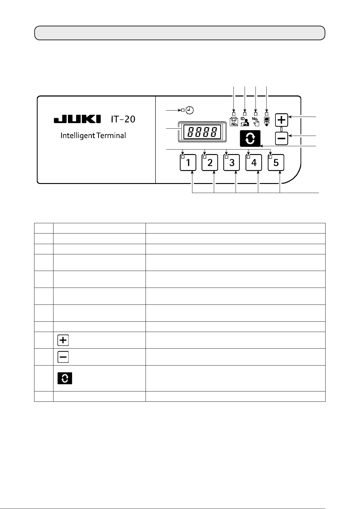
4. CONFIGURATION
A
B
D E F
C
1
2
G
No. Switch/indication Description
Clock LED Lights up when the clock is displayed.
A
7-segment indication block Indicates various ID data and clock information.
B
Product No. LED
C
Operator ID LED
D
Optional ID LED
E
Transmitted data LED
F
No. LED The selected No. will light up.
G
1
2
switch
switch
Lights up when Product No. ID is displayed on
See
→
“5-1. (1) Normal startup mode screen”
Lights up when Operator ID is displayed on
See
→
“5-1. (1) Normal startup mode screen”
Lights up when Optional ID is displayed on
See
→
“5-1. (1) Normal startup mode screen”
Lights up when Transmitted data is displayed on
See
→
“5-1. (1) Normal startup mode screen”
The value to be indicated in B is set up here. The value in-
creases when this switch is pressed.
The value to be indicated in B is set up here. The value de-
creases when this switch is pressed.
The item to be indicated in B is changed here. The indicated
3
4
switch
No. switch Setup information (ID) registered for each item is selected here.
item changes when this switch is pressed.
See
“5-1. Normal startup mode”
→
3
4
.
B
.
.
B
.
.
B
.
.
B
.
.
– 2 –
Page 5
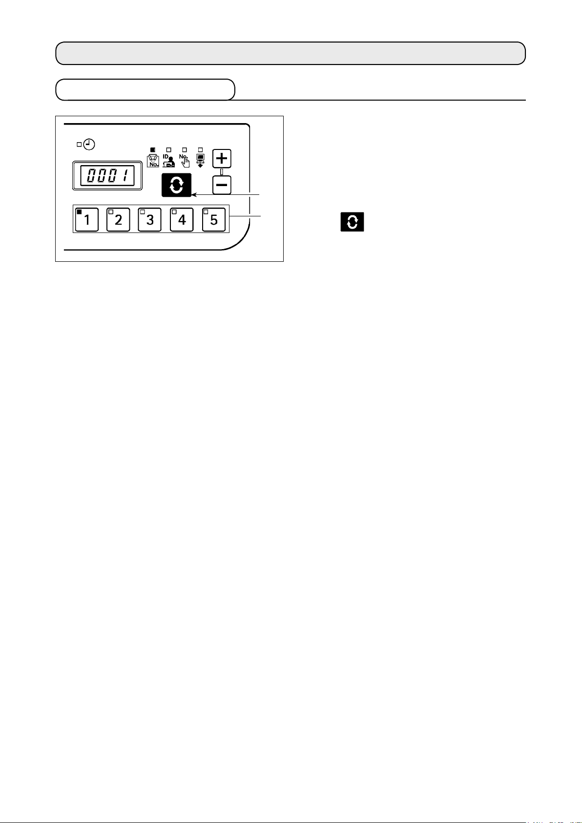
5. BASIC OPERATION PROCEDURE
5-1. Normal startup mode
2
1
When the power supply is turned on, the item screen
and ID data which had been selected before it was
turned off in the previous operation.
The selected item and the number for which the ID is
registered are indicated in LED.
When the No. switch
selected No. is indicated.
When the
screen is displayed.
switch 2 is pressed the following item
is pressed, the ID data for the
1
– 3 –
Page 6
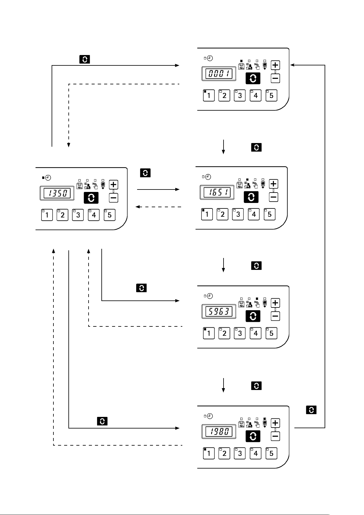
(1) Normal startup mode screen
Press the switch is pressed.
After 3 seconds
Product No. display screen
■
The 16-digit Product No. ID is indicated.
A registered ID can be set up from the No.
switch.
Clock indication
■
The current clock is indicated.
Press the
pressed.
P r e s s t h e
switch is
pressed.
After 3 seconds
s w i t c h i s
After 3 seconds
Operator ID display screen
■
The 8-digit operator ID is indicated.
A registered ID can be set up from the No.
switch.
■
Optional ID display screen
Press the switch is pressed.
Press the switch is pressed.
Press the
switch is pressed.
After 3 seconds
The 8-digit optional ID is indicated.
A registered ID can be set up from the
No. switch.
Press the switch is pressed.
■
Transmission display screen
Up to 16 digits of the transmission
data is indicated.
be set up from the No. switch.
A registered ID can
– 4 –
Press
the
switch is
pressed.
Page 7

ID is indicated successively from the rst 4 digits.
If the ID is 1234 5678 9ABC DEFG, it is indicated as follows and the indication switches to the
clock when the entire ID is indicated.
After 1.5 seconds After 1.5 seconds
Clock indication
After 3 seconds
Whether the clock is automatically displayed after 3 seconds or by pressing the switch can
be selected using the memory switch.
When
the setting to display the clock with the
by pressing the memory switch.
After 1.5 seconds
switch is selected, the selected ID is indicated
(2) No. switch input procedure under normal startup mode
When the 2 out of the 1 to 5 No. switches are pressed successively, ID can be selected from 30 different IDs.
It is considered one-switch operation if one No. switch is pressed and the switch or another switch is not pressed
within 1 second and two-switch operation if the next switch is pressed within 1 second.
* For one-switch operation, the corresponding No. LED lights up. For two-switch operation, the rst No. LED
lights up and the second No. LED blinks.
<e.g.> Inputting “3” (one-switch operation)
<e.g.> Inputting “25” (two-switch operation)
is pressed. ( lights up).
No. switch is input successively for 1 second or lon-
→
ger.
is pressed. ( lights up).
→
T
second (
hen
is pressed successively within 1
blinks).
– 5 –
Page 8

(3) List of No. input patterns by switches
indication: Lights up.
1
2
3
4
5
6
7
8
9
10
First switch
input
No.
Second switch
After 1 second 16
After 1 second 17
After 1 second 18
After 1 second 19
After 1 second 20
indication: Blinks.
input
No.
21
22
23
24
25
First switch
input
Second
switch input
11
12
13
14
15
When No.30 (switches + ) is input, ID will be unselected.
26
27
28
29
30
– 6 –
Page 9

(4) Outputting measurement data
When switch 1 is pressed for one second or
longer under normal mode, USB data writing function
1
is enabled. When
switch 2 is pressed for one
second or longer, network data transmission function is
2
enabled.
“Wait” blinks on the 7-segment indication block during
data output.
In transmission data indication under normal mode, it is possible to indicate 30 different data
depending on the No. switch input combination and check the IP address in a similar fashion to
other ID data indication.
The sewing machine ID can be checked by No. 29 (switches
and the IP address by No. 30 (switches
+ ).
+ ) for transmission data,
e.g. For IP address 192.168.1.106,
1st block
After 1.5 seconds
2nd block
After 1.5 seconds
3rd block
Clock indication
After 3 seconds
4th block
After 1.5 seconds
– 7 –
Page 10

5-2. Setup mode
(1) Setup mode screen
When the power supply is turned on with switch pressed, the system starts up in setup mode.
In setup mode, the setting item
is selected by using
and
switches and conrmed by
using the
switch. When
confirmed, the corresponding
setup screen will be displayed.
After the completion of the set-
ting procedure, turn the power
OFF and re-turn it ON.
■
Setup screen
Press
the
switch.
Press the switch.
■
MAC address check screen
MAC address assigned for each
system can be checked. → See
“5-2. (2) MAC address check screen.”
Press the
switch.
Memory switch setup screen
■
Press the
switch.
Press the
Initialization screen
■
switch.
Panel data initialization is executed. → See
screen.”
Press the
■
USB format screen
“5-2. (5) Initialization
switch.
Press the
switch.
Press the
switch.
The memory switch No. is set up.
See
“5-2. (3) Memory switch
→
setup screen.”
Press the
switch.
Clock setup screen
■
The clock is set up. → See
(4) Clock setup screen.”
Press the
switch.
“5-2.
Press
the
switch.
The medium connected to USB is
formatted. → See
format screen.”
Press the
switch.
IP address check screen
■
The procedure to obtain the IP
address is selected. → See
(7) I
P address setup screen.”
Press the
switch.
Version check screen
■
“5-2. ( 6) USB
Press the
switch.
Press the
switch.
“5-2.
* If this screen appears, turn the power
OFF and re-turn it ON.
– 8 –
The panel version is checked.
See
“5-2. (8) Version check screen.
→
”
Press
the
switch.
Page 11

(2) MAC address check screen
Since MAC address is set up for each device, it can only be checked on the IT panel.
Press the switch 3 to switch the block indication
for MAC address.
3
3
3
3
– 9 –
Page 12

(3) Memory switch setup screen
Panel operation can be varied by changing the memory switch setting.
Press the switch 3 on the memory switch setup
screen and display the memory switch No.
3
1
2
1
2
3
The memory switch can be selected by pressing
switch
or switch 2 in this condition.
1
When the memory switch has been selected, press
the
switch 3 to indicate the setting value A for
the selected memory switch. The setting value can be
changed by pressing the
here, and the setting value is saved by pressing the
2
switch 1 or switch
switch 3 again.
After the completion of the setting procedure, turn the
A
power OFF.
– 10 –
Page 13

Memory Switch Data List
■
No. Description Initial value
U01
U02
U03
U05
U08
U09
U10
U11
U12
U13
U14
Network ofine setting
Network connection validity/invalidity is selected.
OFF : Network connection is enabled.
ON : Network connection is prohibited.
Clock correction function
Clock correction validity/invalidity when there is network connection is set up.
OFF : Clock correction is not enabled.
ON : The panel clock is corrected in reference to the host PC clock when there is net-
work connection.
Indication period for clock indication screen
This item is valid only when the U10 setting is ON.
In how many seconds after displaying the entire ID the clock display screen should be
displayed is set up (unit: seconds).
Buzzer sound ban setting
The buzzer sound from the panel is banned.
OFF: Buzzer is not banned (buzzer sounds).
ON: Buzzer is banned.
Network communication ban for ISS measurement data ON/O
ransmission of ISS measurement data from the network to the PC is banned.
T
OFF : Data is transmitted to PC via network.
ON : Data is not transmitted to PC via network.
Selection of sewing machine rotation signal logic
Follow the setup manual and set up.
Selection of clock screen indication method
Whether the clock display screen is displayed or not after ID indication is selected.
OFF: Clock display screen is not automatically displayed. The clock screen is dis-
played by the scroll switch.
ON : The clock screen is automatically displayed after the set period in U03 after ID
indication.
Indication ID
This item is valid only when U10 is set to OFF.
The type of ID indicated by lighting up the LED on the clock display screen is selected.
0 : Product number
1 : Operator ID
2 : Optional ID
3 : Transmission data
Number of stitches neglected by manual switch
The production count-up input is accepted only when the sewing machine is stopped after thread trimming and the number of sewn stitches exceeds the preset number.
This setting is used for preventing incorrect input or fraudulent input.
Setting range: 0 – 99 (stitches)
Remaining buffer for ISS measurement warning
Warning (E205) is generated when the ISS measurement data capacity stored in the
panel becomes small.
0 : No warning is generated.
1 : A warning is generated when the data capacity to output to the network is becom-
2 : A warning is generated when the data capacity to output to USB is becoming small.
Scroll speed
The scroll speed for displaying IDs larger than 4 digits is set up.
Unit : 0.1 seconds, setting range: 5 (0.5 seconds) to 50 (5.0 seconds)
on clock screen
ing small (if this warning is generated even when the system is connected to the
network, there may be a problem in network connection).
Insert a USB memory in the panel and output data if this warning is generated.
FF
OFF
ON
3
OFF
OFF
0
ON
0
0
1
15
– 11 –
Page 14

(4) Clock setup screen
The year, month, date, hour, minute and second are set up on the clock setup screen.
Press
Clock setup screen
■
■
switch 1 or switch 2 to enter the date and time. Then, conrm the entry by pressing switch 3.
Year setting
Press the switch is pressed.
1
2
3
1
2
3
Hour setting
■
Minute setting
■
Press the
1
2
3
switch is pressed.
1
Month setting
■
Date setting
■
Press the switch is pressed.
Press the switch is pressed.
1
2
3
Second setting
■
Press the
switch is pressed.
Turn OFF the power supply after setting up every-
thing up to second.
1
When it is connected to a network in
2
3
which IA-1 is connected, time is auto-
matically obtained from IA-1.
2
3
1
2
3
Press the
switch is pressed.
– 12 –
Page 15

(5) Initialization screen
Panel data is initialized on the initialization screen.
3
1
2
3
Press the
indicate the initialization No.
The initialization No. can be selected by pressing the
switch 1 or switch 2 in this condition.
0 : Initialization is not executed.
1 : Memory switch and so forth are initialized.
2 : Measurement data is initialized.
3 : Both memory switches and measurement data are
initialized.
switch 3 on initialization screen and
Then, press
and turn the power OFF.
switch 3 to confirm the selection
– 13 –
Page 16

(6) USB format screen
The external medium connected at the USB is formatted on the USB format screen.
1
2
3
1
2
3
“YES” is displayed when the
switch 3 is pressed
on the USB format screen.
“YES” and “NO” are switched by pressing the
switch
Press the
or switch 2.
1
switch 3 while “YES” is displayed to
start formatting the media connected to USB.
“WAIT” will be displayed during formatting, and it re-
turns to the USB format screen when formatting is com-
pleted.
– 14 –
Page 17

(7) IP address setup screen
The method to obtain the IP address is selected on the IP address setup screen.
IP address mode selection
■
DHCP client
Select the method by pressing the
switch 2 with the IP address mode selected, and
1
conrm the selection by pressing the
2
3
When DHCP or APIPA is selected as the method, the
following indication will appear and the screen indica-
tion will stay that way.
1
2
3
switch 1 or
switch 3.
APIPA
1
2
3
– 15 –
Page 18

Manual selection of IP address
■
When manual input is selected, the IP address input
…
screen will appear. Select the IP address using the
1
switch
conrm with the
2
3
* The screen will blink during setup.
When IP address has been set up, press the
switch
the sewing machine.
3
or switch 2 for each block and then
1
switch 3.
to turn OFF the power supply and restart
3
(8) Version check screen
The version data for the panel can be checked on the version check screen.
Select the subject to check the version by pressing the
switch 1 or switch 2 on the version check
screen.
1
2
Switch the indication in order of R-V-L branch numbers
using the
switch 3.
3
– 16 –
Page 19

5-3. Software rewrite mode
When the power supply is turned ON with switch pressed, the system will start up in IT-20 application soft-
ware rewrite mode.
Load the software and press the switch 3 while
“PGWr” is displayed to start software rewrite.
Rewrite cannot be executed if several pro-
grams are written in USB.
3
Rewrite progress (%) is indicated while data is loaded,
and “PoFF” is displayed when it is completed. Turn
OFF the power supply and restart the sewing machine.
Never cut off the power supply or pull out the USB during this process. Neglect may result in main
unit failure.
– 17 –
Page 20

6. ERROR INDICATION
This system enables interlock (or restriction of functions) to prevent the problem from spreading in case a problem
is detected, and contains the following error codes to notify the problems. When requesting for service, please also
check the error code.
Error code display
Error code Error description Restoration method
E011
E012
E013
E015
E016
E021
E065
E067
E204
E205
E206
E915
External medium not inserted
No medium is inserted.
Read error
Data cannot be read from the medium.
Write error
Data cannot be written into the medium.
F
ormat error
The medium cannot be formatted.
External medium capacity exceeded
The capacity of the medium is insufcient.
Medium access failure
Network transmission failure
Data cannot be transmitted to the network.
I
D data reading failure
ID data stored in the medium is corrupt.
USB insertion
The sewing machine was started up with USB inserted.
Remaining ISS buffer capacity warning
The buffer for ISS data storage is going to be full soon. When it is
full and used, data will be erased from the oldest ones.
Warning about the logic of sewing machine rotation signal
The sewing machine rotation signal cannot be acquired.
Check the setting of the memory switch U09 referring to the
Setup Manual.
Operation panel ⇔ electrical BOX communication error
Error occurred in data communication.
Reset (Press the
Reset (Press the
Reset (Press the
Reset (Press the
Reset (Press the
Reset (Press the
Reset (Press the
Reset (Press the
Reset (Press the
Reset (Press the switch.)
Reset (Press the
Turn OFF the power
switch.)
switch.)
switch.)
switch.)
switch.)
switch.)
switch.)
switch.)
switch.)
switch.)
E938
E949
E950
Error in program rewriting le
No le for program rewriting
There are several les for program rewriting.
Turn OFF the power
Turn OFF the power
Turn OFF the power
For some models of the sewing machines, errors are not saved as ISS data.
– 18 –
 Loading...