

Page 1

IT-100
INSTRUCTION MANUAL
I
Page 2

CONTENTS
日本語日本語
. INTRODUCTION
Ⅰ
. SETTING
Ⅱ
.................................................................................................. 2
...................................................................................... 1
1. INITIAL SETTING .........................................................................................................2
1-1. Machine head settings ................................................................................................................2
1-2. Adjusting the machine head angle (direct-drive motor type sewing machine only) ............................ 3
1-3. Adjusting the contrast of the operation panel screen .............................................................4
1-4. Connecting the count manual switch ........................................................................................ 4
1-5. USB port .......................................................................................................................................4
2. HOW TO SET THE PRODUCTION SUPPORT FUNCTION ........................................ 5
2-1. Overview of the work support function ..................................................................................... 5
2-2. Displays on the screen for the production support function .................................................. 6
2-3.Settingproceduretobetakenbeforerstuse ......................................................................... 7
(1) Enabling the operation of the production support function. ..................................................7
(2) Setting the date and time ........................................................................................................... 9
(3) Setting other setting items ........................................................................................................9
2-4. Setting procedure to be taken before regular operation .......................................................10
(1) Setting the date and time .........................................................................................................10
(2) Setting the enable/disable of the production support function ............................................ 11
(3) Setting the sewing recorder function .....................................................................................12
(4) Setting the production management function ...................................................................... 13
(5) Setting common data for the production support function .................................................. 17
. OPERATION
Ⅲ
........................................................................................... 19
1. CONFIGURATION OF THE OPERATION PANEL .....................................................19
2. SEWING SCREEN ...................................................................................................... 21
3. HOW TO OPERATE A SEWING PATTERN ............................................................... 24
3-1. Reverse stitching pattern..........................................................................................................24
3-2. Overlapped stitching pattern .................................................................................................... 26
3-3. Programmed stitching pattern .................................................................................................27
3-4. Cycle sewing pattern ................................................................................................................. 31
4. HOW TO OPERATE THE COMMON FUNCTIONS .................................................... 33
4-1. Bobbin counter ..........................................................................................................................33
4-2. Setting the maximum sewing speed ........................................................................................ 34
4-3. Setting the backlight .................................................................................................................34
4-4. Re-sewing switch .......................................................................................................................35
4-5. Needle up/down compensation switch ....................................................................................35
4-6. On/off switch of the material edge sensor ........................................................................ 36
4-7. Automatic thread trimming switch ....................................................................................36
4-8. One-shot automatic stitching switch .................................................................................36
4-9. Thread trimming prohibition switch .................................................................................. 36
4-10. Simpliedfunctionsetting ........................................................................................................ 37
4-11. Key-lock function setting ..........................................................................................................38
4-12. Function setting .........................................................................................................................39
4-13. Optional input/output settings .................................................................................................45
i
Page 3

4-14. Automatic compensation of neutral point of the pedal sensor .............................................46
4-15. Initialization of the setting data ................................................................................................47
5. HOW TO OPERATE THE PRODUCTION SUPPORT FUNCTION ............................ 48
5-1. How to change over the screen under the normal sewing mode .........................................48
5-2. Operating the work management screen ................................................................................49
(1) Work management screen .......................................................................................................49
(2) Sewing product's product number selection screen ............................................................50
(3) Operator ID selection screen ................................................................................................... 50
(4) Optional ID selection screen ...................................................................................................51
(5) No. of pcs. in lot input screen .................................................................................................51
(6) Communication selection screen ...........................................................................................52
5-3. Operating the pitch time monitor screen ................................................................................53
(1) Pitch time monitor screen No. 1 .............................................................................................. 53
(2) Pitch time graph mode .............................................................................................................55
(3) Pitch time monitor screen No. 2 .............................................................................................. 57
5-4. Operating the sewing recorder .................................................................................................58
(1) Sewing recorder screen No. 1 .................................................................................................58
(2) Sewing recorder screen No. 2 .................................................................................................60
(3) Uploading/downloading the sewing recorder data ...............................................................61
5-5. Operating the production management function ...................................................................62
(1) Production management screen No. 1 ...................................................................................62
(2) Production management screen No. 2 ...................................................................................64
. INFORMATION
Ⅳ
....................................................................................... 65
1. OPERATOR LEVEL ................................................................................................... 65
1-1. Sewing management information ............................................................................................65
(1) Maintenance management function ........................................................................................65
(2) Working measurement function .............................................................................................. 69
1-2. Setting the date and time .......................................................................................................... 70
2. MAINTENANCE PERSONNEL LEVEL ......................................................................71
2-1. Sewing common data screen ................................................................................................... 72
2-2. Memory switch setting .............................................................................................................. 76
2-3. Network setting .......................................................................................................................... 78
. EXTERNAL INTERFACE
Ⅴ
. ERROR
Ⅵ
................................................................................................... 80
....................................................................... 80
1. ERROR DISPLAY ....................................................................................................... 80
2. ERROR CODE LIST (ERROR DISPLAY IN PANEL) ................................................. 81
ii
Page 4
!
. INTRODUCTION
This Instruction Manual describes JUKI operation panel "IT-100".
Be sure to read "Safety precautions" in the Instruction for the SC-920 (control box) before reading this In-
struction Manual to fully understand them.
In addition, this product is precision equipment. It requires careful handling. Take care not to drop or
roughly handle it to protect against any physical shock.
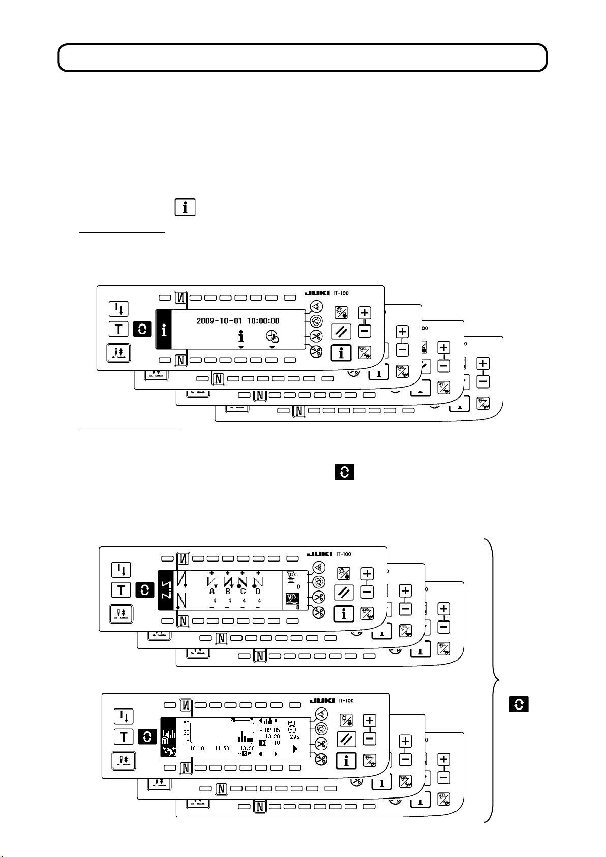
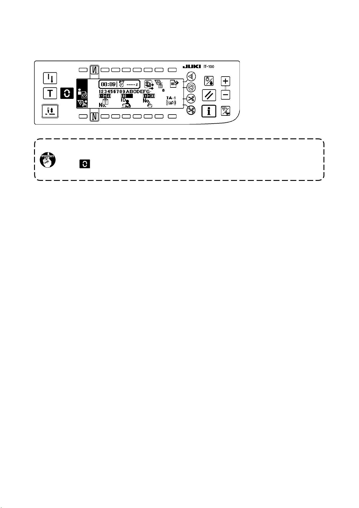
The operations of the IT-100 operation panel mainly consist of those carried out under the "normal sew-
ing mode" and those under the "information mode." These two modes can be changed over by means of
the information switch .
Information mode
Under this mode, function settings for the production support function are carried out and the sewing
machine operation is set/checked.
Refer to
"$. INFORMATION"
for how to operate the operation panel under the information mode.
Normal sewing mode
Under this mode, the sewing machine performs sewing.
The sewing screen differs on a model-by-model basis. It is possible to use the IT-100 by changing
over the screen, with the Screen changeover switch , between the sewing screen and the production support function screen on which the production support operation is enabled.
Refer to
mode.
<Sewing screen which differs on a model-by-model basis>
<Production support function screen on which the production support operation is enabled>
"#. 2. SEWING SCREEN
" for how to operate the operation panel under the normal sewing
P r e s s
t h e
s w i t c h
.
– 1 –
Page 5
@
. SETTING
1. INITIAL SETTING
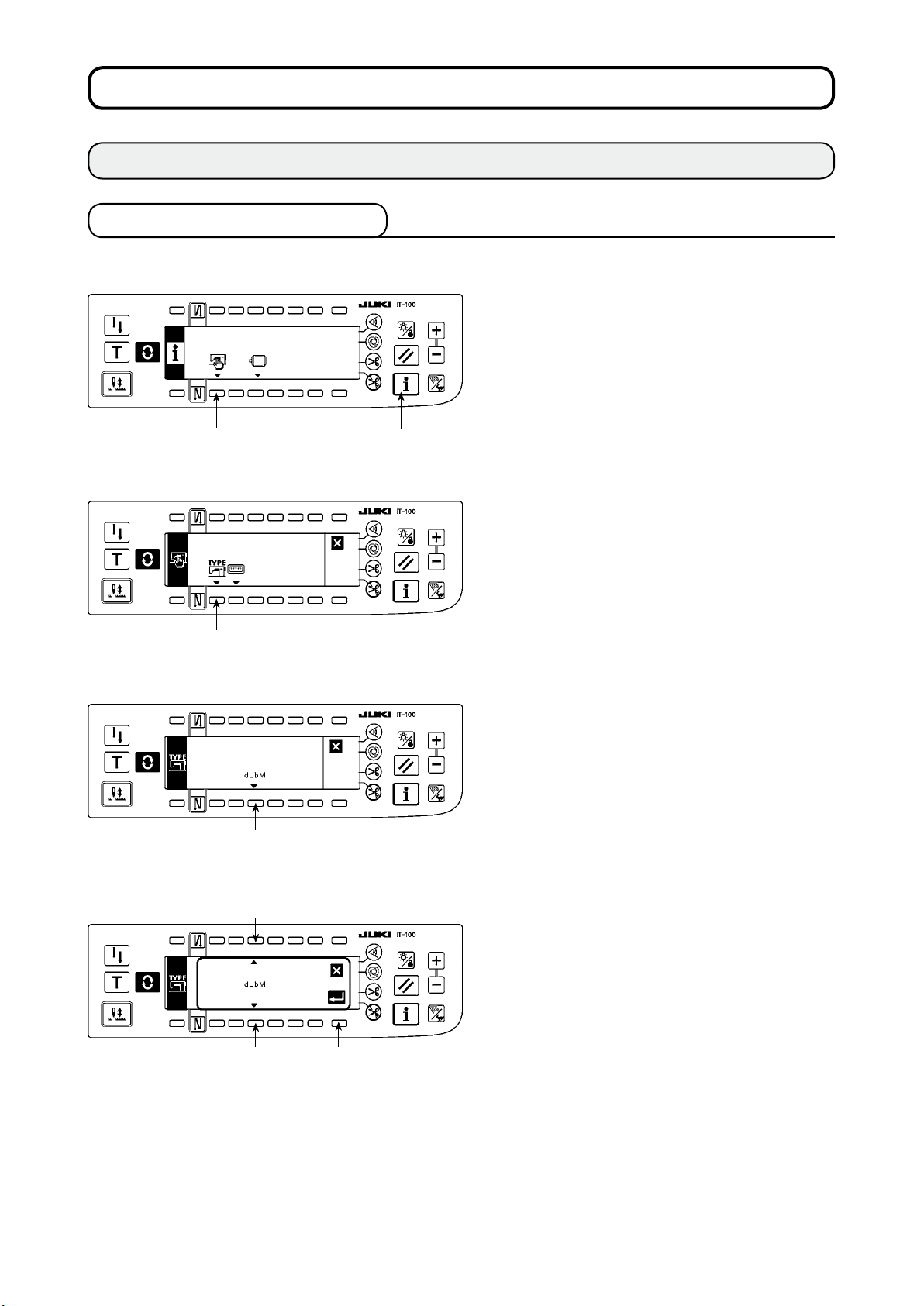
1-1. Machine head settings
[Function settings list screen]
2
[Sewing common data screen]
1) Keeping switch 1 held pressed, turn the pow-
er ON. Then the screen is changed over to the
function settings list screen.
When you p ress switch 2, the scree n is
changed over to the s ewing common data
screen.
1
2) When you p ress switc h 3, the scre en is
changed over to the machine head type dis-
play screen.
3
[Machine head type display screen]
4
[Machine head type setting popup screen]
5
6 7
3) The displayed machine head type is the ma-
chine head you have selected. When y o u
press switch 4, the screen is changed over to
the machine head type setting popup screen.
4) You may selected the machine head as de-
sired by pressing switches
* Refer to the separate sheet of "Sewing ma-
chine setup precaution" or the "Machine head
list" given on the separate sheet for the ma-
chine head types.
and 6.
5
5) Once you have determined the machine head
type, press switch 7. The screen is changed
over to the “machine head type display screen"
to display the machine head type you have se-
lected. Turn the power switch OFF to exit from
the machine head setting.
– 2 –
Page 6
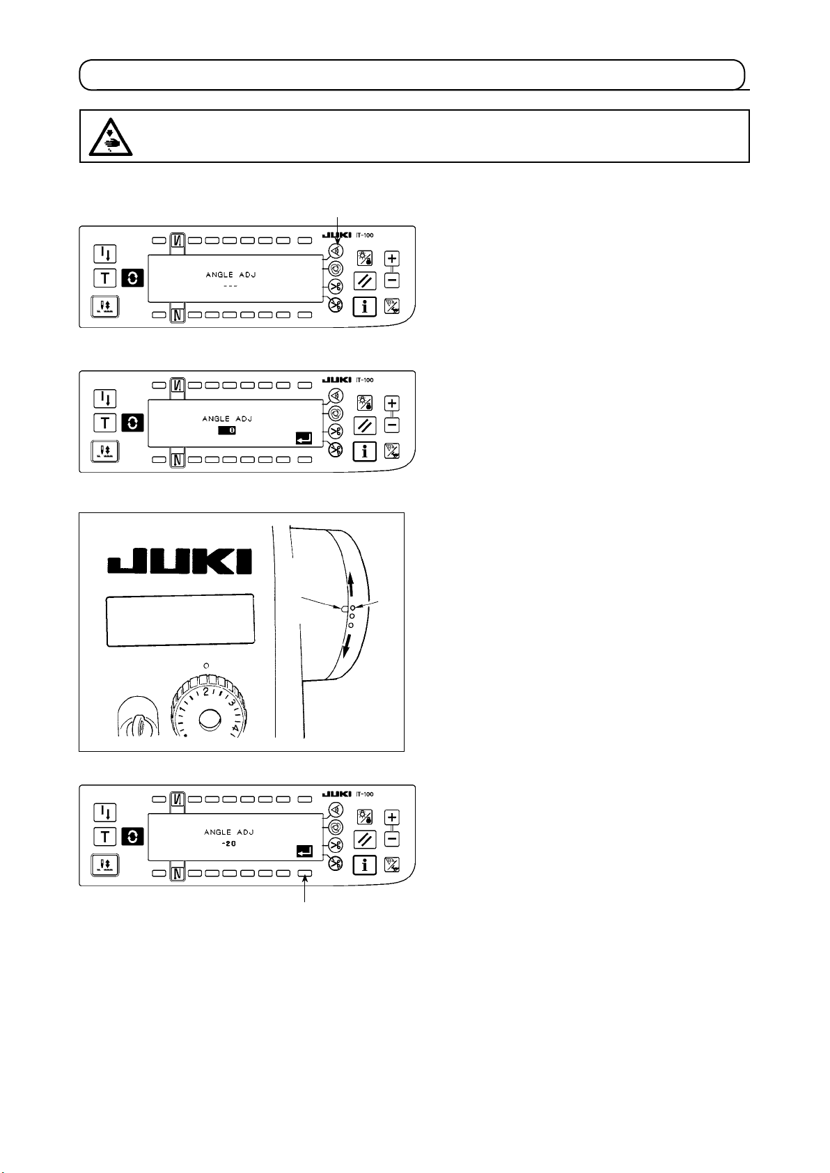
1-2. Adjusting the machine head angle (direct-drive motor type sewing machine only)
WARNING :
If the white marker dot on the pulley is far out of alignment with the recess on the pulley cover, it is
necessary to adjust the angle of the machine head taking the steps of procedure described below.
[Machine head angle adjusting screen]
1
1) Keeping switch
ON. Then the screen is changed over to the
machine head angle adjusting screen.
2) Turn the machine head pulley by hand until the
main shaft reference signal is detected. Then,
the angle transmitted by the main shaft refer-
ence signal is displayed in reverse video. (The
value shown in the gure is a value for refer-
ence.)
held pressed, turn the power
1
3
4
2
3) In this state, align the white dot 2 of the hand-
wheel with the concave 3 of the handwheel
cover as shown in the gure.
4) Once the angle is determined, press switch
The angle displayed in reverse video is now
displayed in normal video and the angle is re-
placed by the adjusted one. Turn the power
switch OFF to exit from the angle adjustment.
4
.
– 3 –
Page 7
1-3. Adjusting the contrast of the operation panel screen
Light
2
A
Shade
3
1
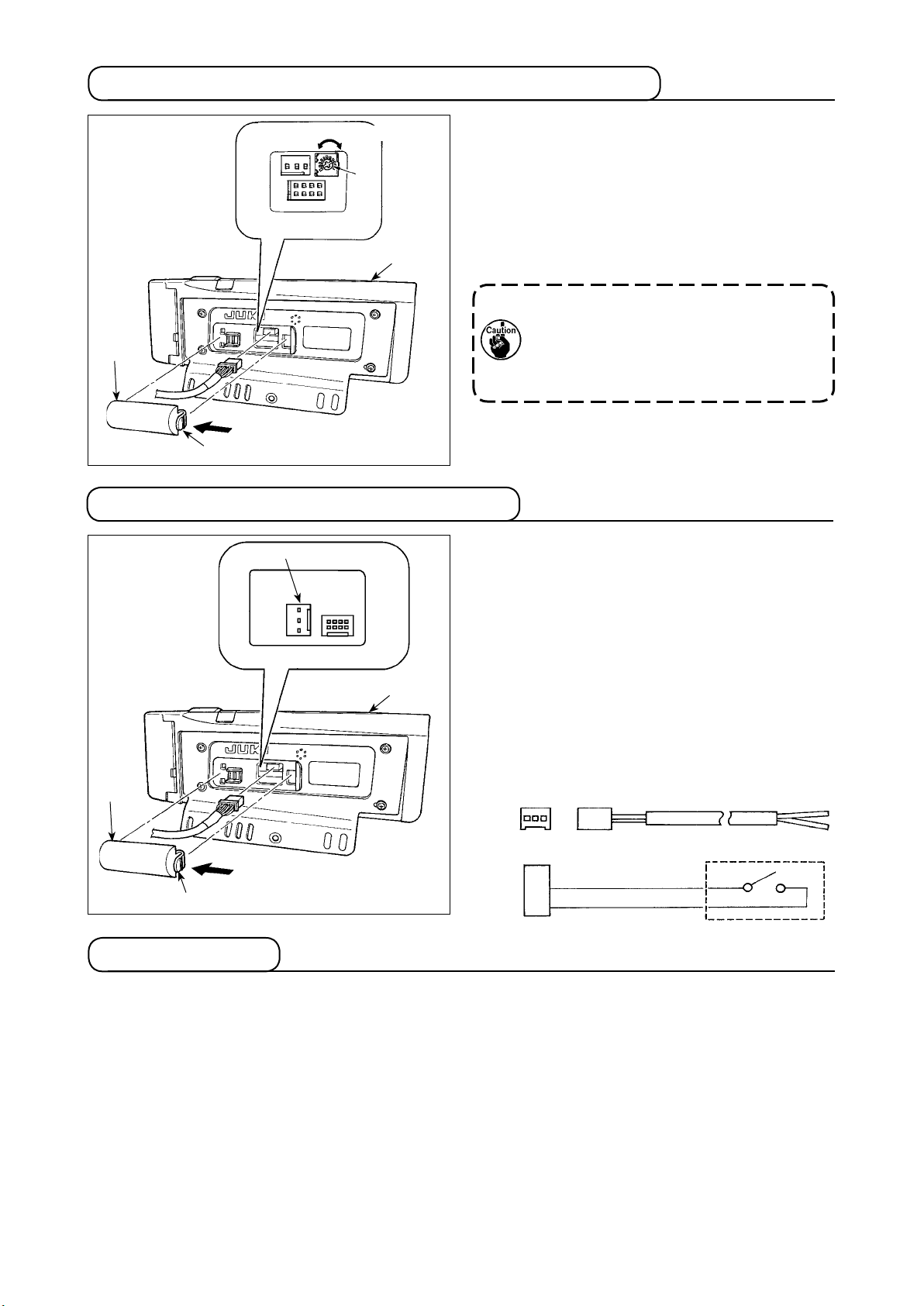
1-4. Connecting the count manual switch
3
1
2
1) Press in the direction of arrow mark the click of
section A of cord outlet cover 2 assembled in
rear of operation panel 1 and remove the
the
cover.
2) Turn
LCD screen display brightness adjustment
variable resistor 3 to adjust the br
ightness (con-
trast) of LCD screen.
2. Do not disassemble the operation pan-
1. To prevent the op eration panel from
breakage, do not touch the circuit board
pattern and the connector terminal.
el to prevent it from breakage.
1) Press in the direction of arrow mark the click of
section A of cord outlet cover 2 assembled in
the rear of operation panel 1 and remove the
cover.
2) Connect optional junction cable connector to
connector CN105 3 of the count manual switch.
Note) Pr e pa re th e s wi tc h m ai n u ni t b y the
customers or ask JUKI business office
about it.
Optional relay cable A (asm.)
JUKI Part No. 40008168
3 2 1
CN105
A
+ 5V
SW
GND
1
2
3
1-5. USB port
Precautions to be taken when handling USB devices
1
• Do not leave the USB device or USB cable connected to the USB port while the sewing machine is in operation. The machi
breakage of the USB device or sewing machine.
• Do not insert/remove a USB device during reading/writing a program or sewing data.
It may cause data breakage or malfunction.
• When the storage space of a USB device is partitioned, only one partition is accessible.
• Some type of the USB device may not be properly recognized by this sewing machine.
•
JUKI does not compensate for loss of data stored on the USB device caused by using it with this sewing machine.
USB specications
2
• Conform to USB 1.1 standard
• Format supported _____
• Consumption current ___
ne vibration can damage the port section resulting in loss of data stored on the USB device or
FAT 32
The rated consumption current of the applicable USB devices is 500 mA at the maximum.
– 4 –
Page 8

2. HOW TO SET THE PRODUCTION SUPPORT FUNCTION
2-1. Overview of the work support function
The production support function is achieved by installing the IT-100 operation panel (Intelligent Terminal) to
the sewing machine and operating it. This function measures the operating status of the sewing machine and
visually displays the measured data on the operation panel to help improve efciency of sewing work in vari-
ous aspects. Measured and recorded data on the operation status of the sewing machine can be loaded on
a personal computer by way of Ethernet or various data storage media. It is therefore possible to analyze the
data by means of IA-1 and to accumulate the results of the analysis on the personal computer by gathering
detailed operation data from two or more sewing machines and loading them on the personal computer. As a
result, the continued efciency-improving activities for the entire sewing plant can be carried out.
* Refer to the Help for the IA-1 for the details of the IA-1.
The production support function by means of the IT-100 is categorized into four functional parts, i.e., work
management function, pitch time monitor function, sewing recorder function and production management
function. Each of them has its own support capability. Use them by selecting an appropriate one according to
your needs.
* It should be noted that the work management function cannot be disabled since it manages data on the
sewing machine operation. Operation of the other three functions can be changed over between the enable and disable.
(1) Work management function
To use the work management function, work history data such as the operator ID, product number and
process number, which are to be embedded in the operation data recorded by each sewing machine,
should be entered. The IA-1 carries out operational status analysis based on those pieces of data.
This function is also used when loading the operation data from the sewing machine into a personal com-
puter.
(2) Pitch time monitor function
With the pitch time monitor function, it is possible to specify an arbitrary target section to monitor the
transition of the production volume (i.e., the quantity of sewn items) per unit time and the pitch time distribution and display them on the IT-100 as a bar chart. In addition, the operational status such as the
total production volume and average pitch time in the specied section can be analyzed and indicated
numerically. Through these capabilities, the sewing work can be monitored over a long time and visually
analyzed to enable tracking down of the time when a problem has occurred.
(3) Sewing recorder function
The sewing recorder function continuously measures the number of revolutions and thread trimming
timing of the sewing machine at all times to show the results on the IT-100 as a line chart. The sewing
machine operator's skill level is checked and technical training is provided based on the line graph. It is
possible to display an operator's skill level together with that of a skilled operator or with his/her work data
of the past on a screen for the purpose of comparison, so that the complicated and hard-to-understand
sewing machine operation can be visualized for easier analysis.
(4) Production management function
The production management function displays the target production volume for given working hours and
the actual production volume to notify the operator of a delay or progress of sewing work in real time.
With this function, the operator is able to carry out his/her work while checking his/her work pace. This
enhances his/her motivation to achieve his/her goal, thereby leading to a increase in productivity. In addition, this function allows early detection of a delay in work making it possible to identify a problem and
take an appropriate measure at an early stage.
– 5 –
Page 9
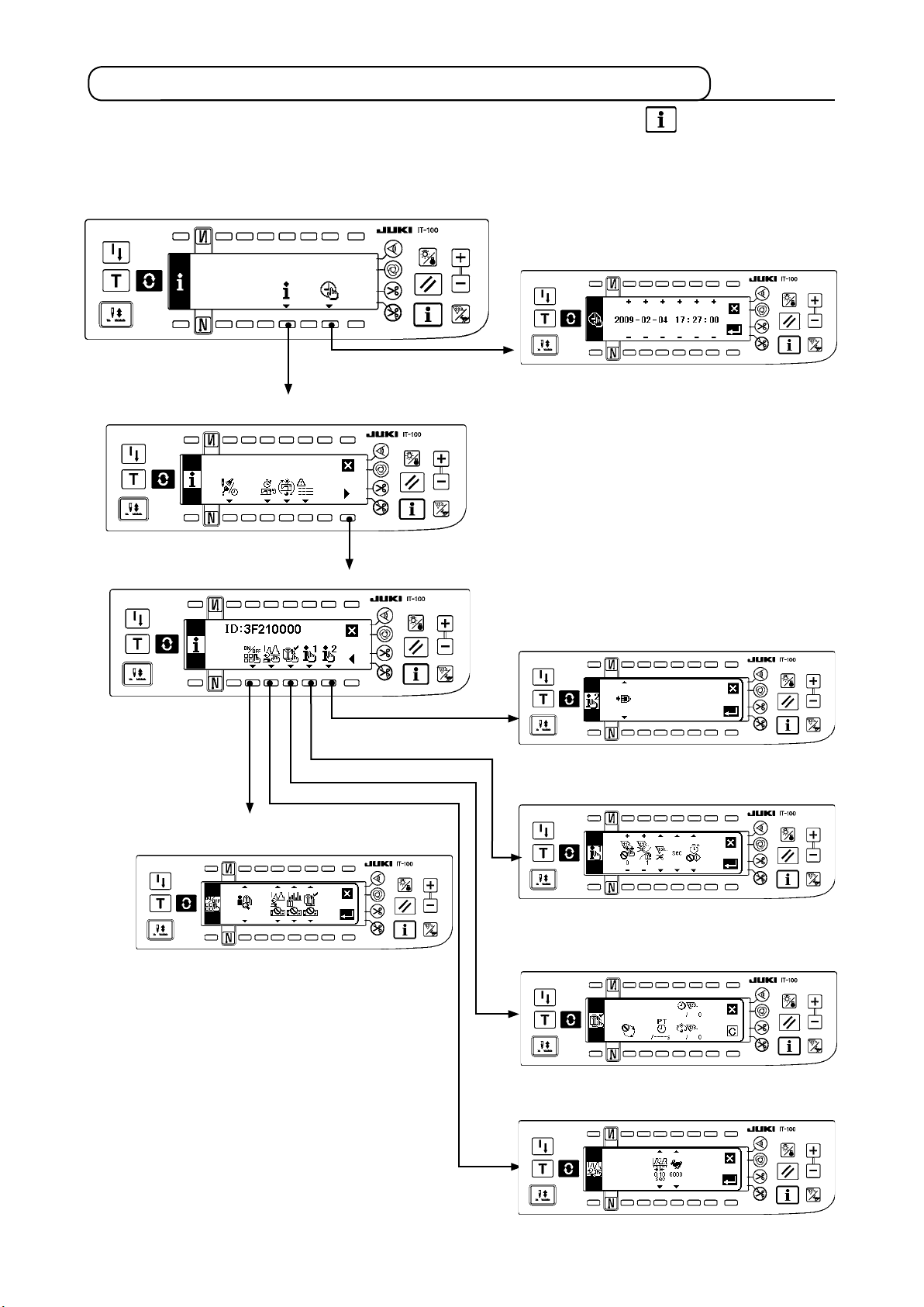
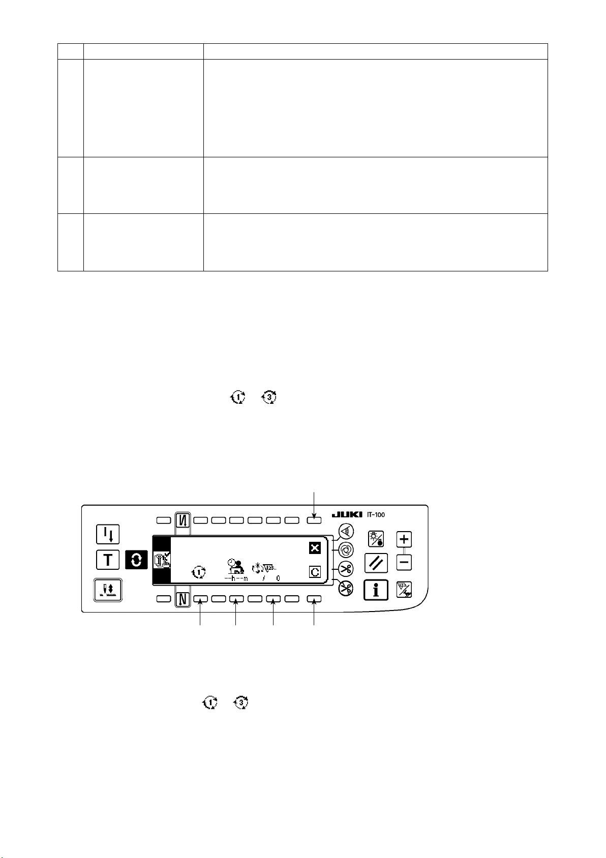
2-2. Displays on the screen for the production support function
The production support function is to be set on the information screen. Press the switch to call the infor-
mation screen. Refer to the item page given under the screen for detailed explanation of the operation setting
procedure for each screen.
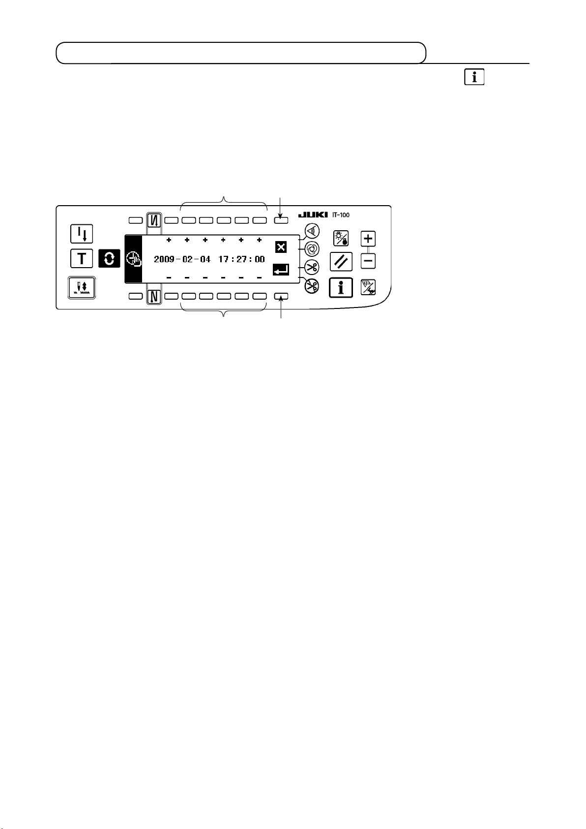
<Information mode screen No.1>
<Date and time setting screen>
Pressed for three seconds
@
. 2-3.(2) Setting the date and time
<Sewing management information screen No.1>
<Sewing management information screen No.2>
<Production support function operation enable/disable setting screen>
@
. 2- 4 . ( 2) Se t ti n g th e en a b l e/ d i s ab l e of th e
operation of the production support function
<ISS setting screen>
@
. 2-4.(5)-2 ISS setting screen
<Production support common setting screen No. 1>
@
. 2-4.(5)-1 Production support common s et ti ng
screen No. 1
<Production management function setting screen>
– 6 –
@
. 2 - 4 .(4) S e t t ing th e prod u c t ion ma n a g ement
function
<Sewing recorder function setting screen>
@
. 2-4.(3) Setting the sewing recorder function
Page 10
2-3.Settingproceduretobetakenbeforerstuse
To use the production support function, the “production support function operation enable setting” and “date
and time setting” have to be carried out without exceptions. Be sure to enter data on the required items fol-
lowing the steps of procedure described below.
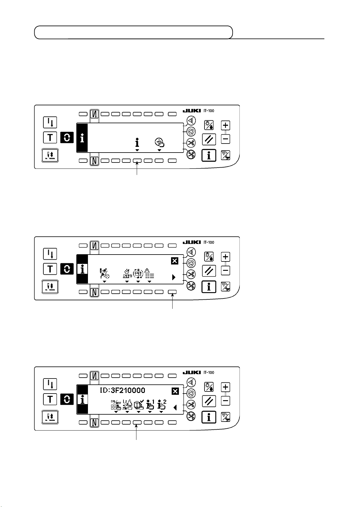
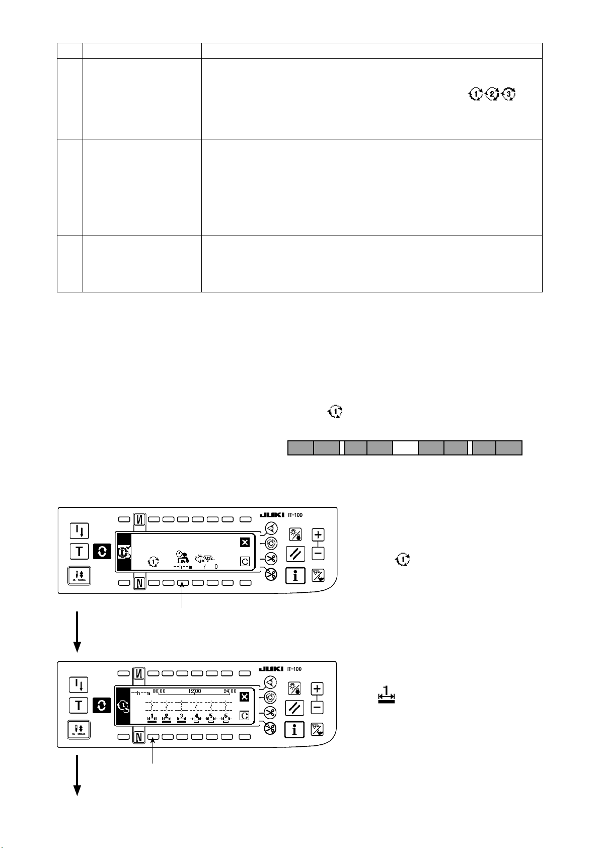
(1) Enabling the operation of the production support function.
<Information mode screen No.1>
1
1) Keep switch 1 on the information mode screen No. 1 held pressed for three seconds to display the sew-
ing management information screen No. 1 (Maintenance personnel level).
<Information mode screen No.2>
2
2) On the sewing management information screen No. 1, press sewing management information screen No.
2 changeover switch 2 to display the sewing management information screen No. 2.
<Sewing management information screen No.2>
3
3) Then press Production support function operation enable/disable changeover switch 3 to display the
production support function operation enable/disable setting screen.
– 7 –
Page 11
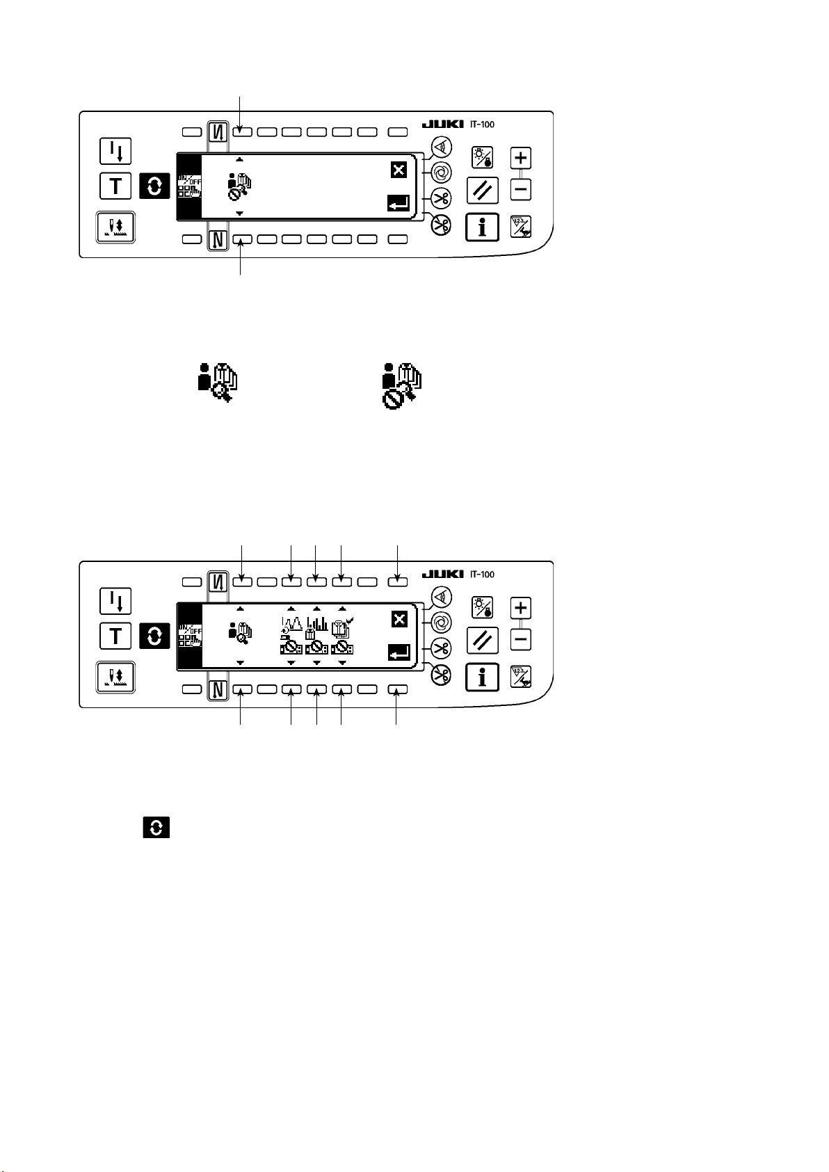
<Production support function operation enable/disable setting screen>
❹
❹
4) Select the enable for the operation of the production support function with Function selector switch
❹
.
Operation of the production
support function is enabled
When the operation of the production support function is enabled, the item for setting display/non-display of
the pitch time monitor function screen, sewing recorder function screen and production management function
screen additionally appears to allow the respective functions to be used under the normal sewing mode.
<Production support function operation enable/disable setting screen>
❷
❷
❸ ❹ ❺
❸ ❹ ❺
Operation of the production
support function is disabled
❼
❻
5) Select the function to be used from among the sewing recorder function, pitch time monitor function and
production management function and set its display status between the display and non-display using
switches ❸, ❹ and ❺. The screen of the function which is set to the display is displayed by pressing the
switch
It should be noted, however, the work management function screen is displayed only by setting the oper-
ation of the production support function to the enable with Function selector switch ❷ because the infor-
mation common to all of the functions need to be managed on this screen.
Switch ❸ : Used to set the sewing recorder function screen to the display/non-display
Switch ❹ : Used to set the pitch time monitor function screen to the display/non-display
Switch ❺ : Used to set the production management function screen to the display/non-display
6) When Enter switch
displayed.
*
If the date and time have already been set, the sewing machine ID setting screen is displayed. If the sewing ma-
chine ID has also been set, the screen is restored to the sewing management information screen No. 2.
When Cancel switch ❼ is pressed, the settings will be cleared and the screen will be restored to the sew-
ing management information screen No. 2.
under the normal sewing mode.
is pressed, the input settings are conrmed and the date and time setting screen is
❻
– 8 –
Page 12
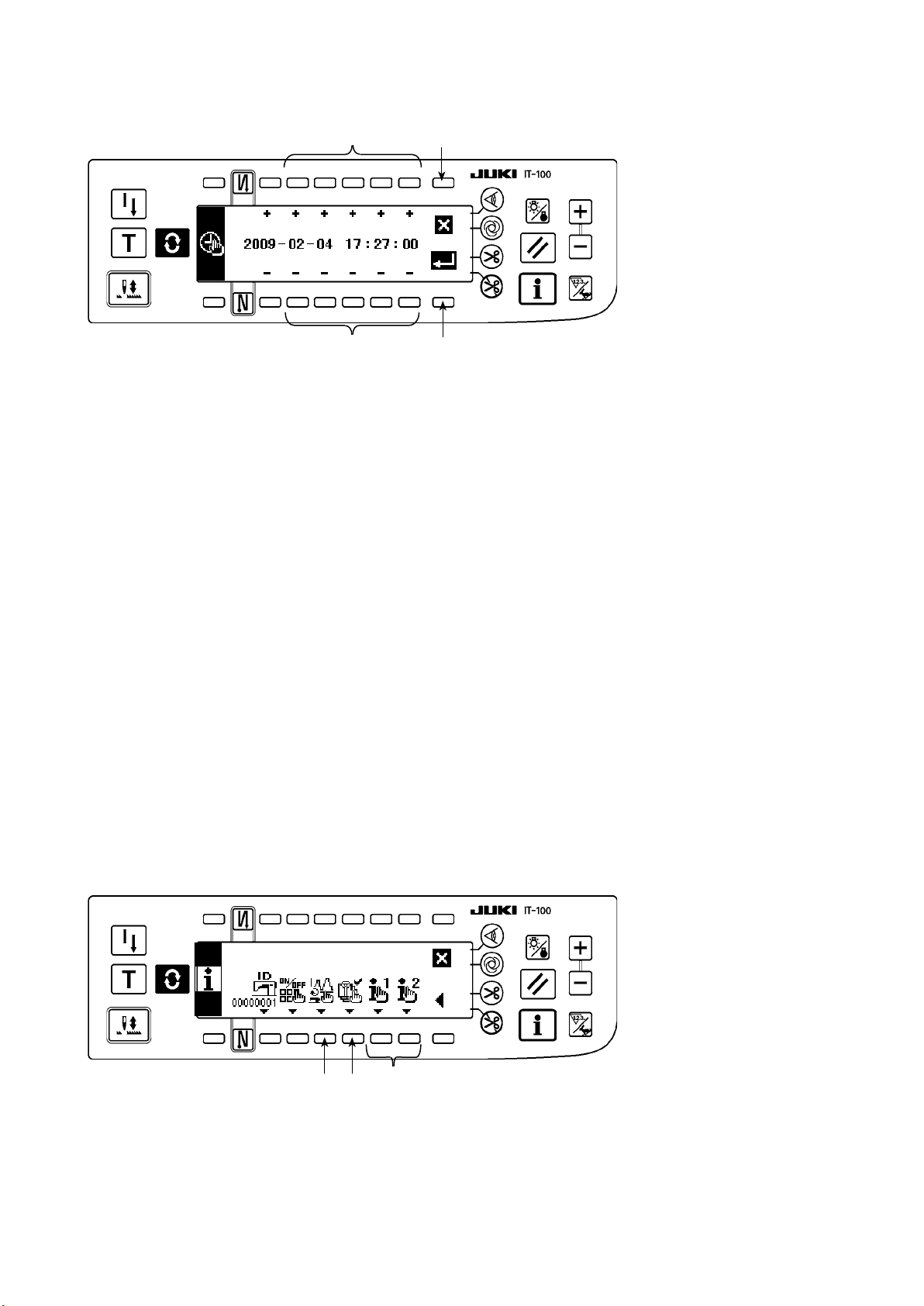
(2) Setting the date and time
<Date and time setting screen>
❽
❽
1)
Set the current date and time with Time setting switch ❽. If any date which does not exist on a calendar
(such as the 31st and a leap year) is set, the relevant date will be shown in black-and-white reverse video.
2) When Enter switch
displayed.
3) If any date which does not exist on a calendar (black-and-white reverse video) is set, a prohibition sound
sounds and cannot be conrmed.
When Cancel switch
sewing management information screen No. 2.
is pressed, the settings are conrmed and the sewing machine ID setting screen is
❾
is pressed, the settings will be cleared and the screen will be restored to the
❾
(3) Setting other setting items
2-3 (1) Enabling the production support function operation" and "
When you complete "
Setting the date and time" according to this Instruction Manual, the screen returns to the sewing manage-
ment information screen No. 2. The following setting items can be set through this screen.
On this screen, the following can be carried out :
Switch
Switch
Switch
Carry out setting according to the usage of the sewing machine.
* Refer to
<Sewing management information screen No.2>
: Setting the details of the sewing recorder function
❶
: Setting the details of the production management function
❷
: Setting the common items for the production support
❸
"Ⅱ. 2-4. Setting procedure to be taken before regular operation" for details of setting procedure.
Ⅱ
.
2-3 (2)
.
Ⅱ
❶
❷
❸
– 9 –
Page 13
2-4. Setting procedure to be taken before regular operation
To set data on the operation of the production support function, press the Information switch under the
normal sewing mode to change over to the information mode.
(1) Setting the date and time
* Refer to
cedure to be taken until this screen is displayed.
<Date and time setting screen>
1) Set the current date and time with Time setting switch
* If any date which does not exist on a calendar (such as the 31st and a leap year) is set, the relevant date
will be shown in black-and-white reverse video and the setting cannot be conrmed.
2) When Enter switch
is cancelled and the screen is restored to the previous one.
"@. 2-2. Displays on the screen for the production support function"
8
8
is pressed, the setting is conrmed. When c
9
!0
9
8
.
ancel switch !0 is pressed, the setting
for the operating pro-
– 10 –
Page 14
(2) Setting the enable/disable of the production support function
* Refer to
"@. 2-2. Displays on the screen for the production support function"
for the operating pro-
cedure to be taken until this screen is displayed.
On the <Production support function operation setting screen> under the information mode, the enable/disable setting for the entire production support function can be carried out, and the display/non-display setting
for the sewing recorder function screen, pitch time monitor function screen and production management
function screen can be carried out on function-by-function basis.
<Production support function operation enable/disable setting screen>
1
1
2
2
3 4
3 4
6
5
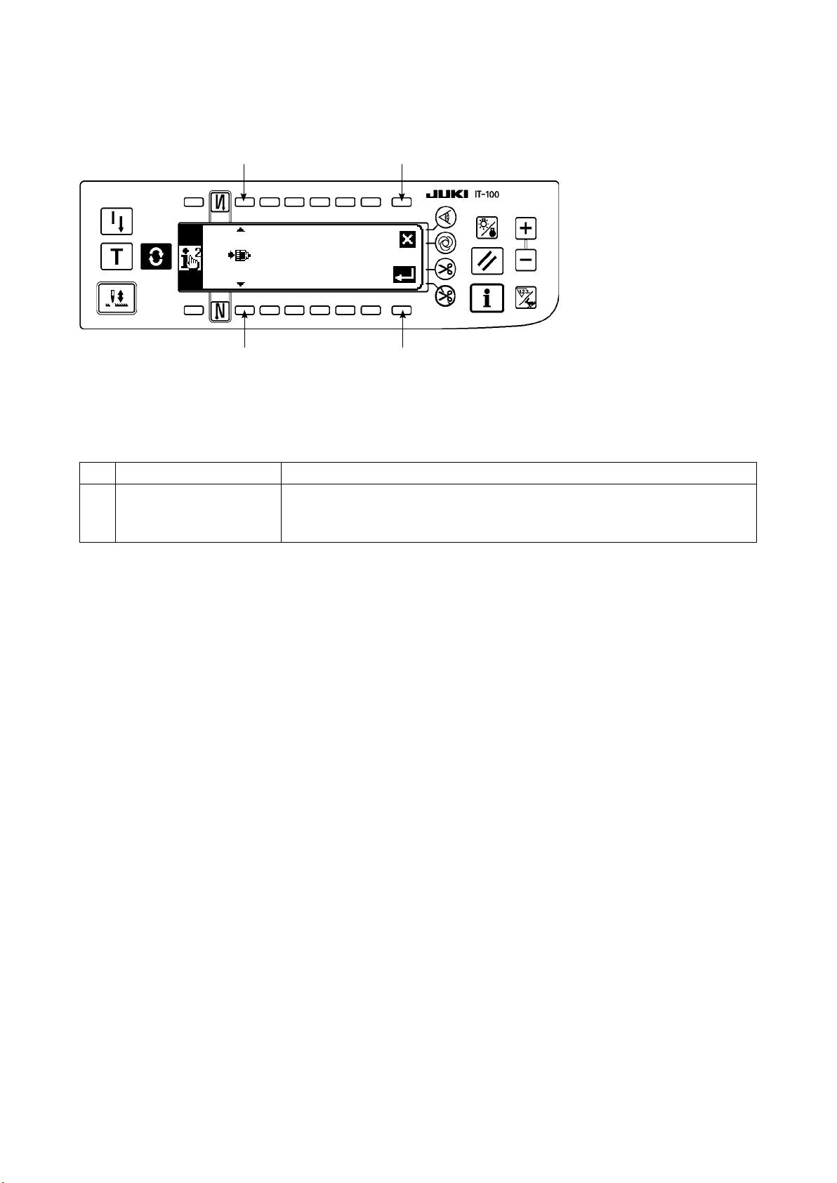
Input the item to be set referring to the table given below.
When
Enter switch
is pressed, the input data is conrmed. When
5
Cancel switch
is pressed, the input
6
data is cancelled and the screen is restored to the previous screen.
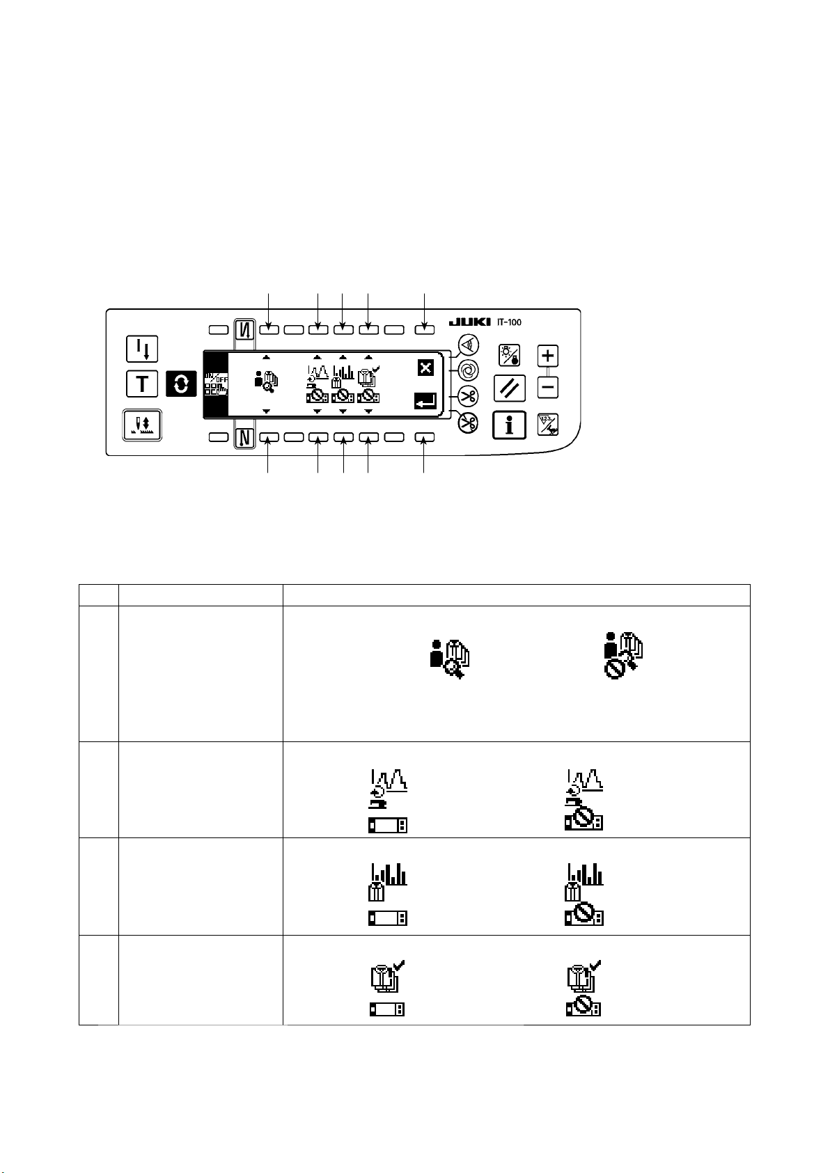
No. Item to be set Description
Enable/disable of the op-
1
eration of the production
support function
Di s p lay/non-d i s play of
2
t h e se w i ng re c o r de r
screen
Di s p lay/non-d i s play of
3
the pitch t i m e monitor
screen
Di s p lay/non-d i s play of
4
the production manage-
ment screen
Enable/disable of the operation of the entire production support function is set.
Operation enabled : Operation disabled :
* When the operation is enabled, items
display of the sewing recorder screen, pitch time monitor screen and production
management screen additionally appear on the screen.
Display/non-display of the sewing recorder screen is set. (*1)
Display : Non-display :
Display/non-display of the pitch time monitor screen is set. (*1)
Display : Non-display :
Display/non-display of the production management screen is set. (*1)
Display : Non-display :
2
to
for setting the display/non-
4
*1. When the screen is set to the display, the screen is added to the normal sewing mode screen and it be-
comes available.
Refer to
"#. 5-1. How to change over the screen under the normal sewing mode"
for the operating
procedure under the normal sewing mode.
– 11 –
Page 15
(3) Setting the sewing recorder function
* Refer to
"@. 2-2. Displays on the screen for the production support function"
for the operating pro-
cedure to be taken until this screen is displayed.
The operation and the display-related basic items of the sewing recorder function can be set on the <Sewing
recorder function setting screen> under the information mode.
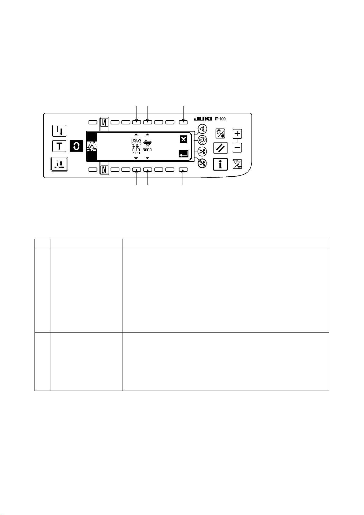
<Sewing recorder function setting screen>
4
3
Cancel switch 4 is pressed, the input
Input data on items
When Enter switch
2
1
2
1
and
1
is pressed, the input data is conrmed. When
3
referring to the table given below.
2
data is cancelled and the screen is restored to the previous screen.
No. Item to be set Description
Data sampling time Sets the time interval for measuring and recording the sewing speed of the sew-
1
ing machine.
Set value : 0.05, 0.10, 0.50, 1.00, 1.50, 2.00 (sec)
Initial value : 0.10 (sec)
* Data over the time interval specied by the set value "0.05: 25 minutes," "0.10:
50 minutes," "0.50: 250 minutes," "1.00: 500 minutes," "1.50: 750 minutes," or
"2.00: 1000 minutes" can be stored in memory of the sewing machine. When
the memory capacity is exceeded, the oldest piece of data is erased to store
the latest piece of data at all times.
* The accuracy of the graph plotted depends on the time interval set vale.
Upper limit value of ver-
2
tic a l a x is of th e c h ar t
(sewing speed)
The upper limit of the graph displayed on the sewing recorder screen No. 2 is
set.
Set value : 6000, 9000 (sti/min)
Initial value : 6000 (sti/min)
* On the sewing recorder screen No. 2, the graph can be used under the auto
range mode or by setting an arbitrary range in increments of 1000 (sti/min) not
more than the upper limit.
– 12 –
Page 16
(4) Setting the production management function
* Refer to
cedure to be taken until this screen is displayed.
The operation and the display-related basic items of the production management function can be set on the
<Production management function setting screen> under the information mode.
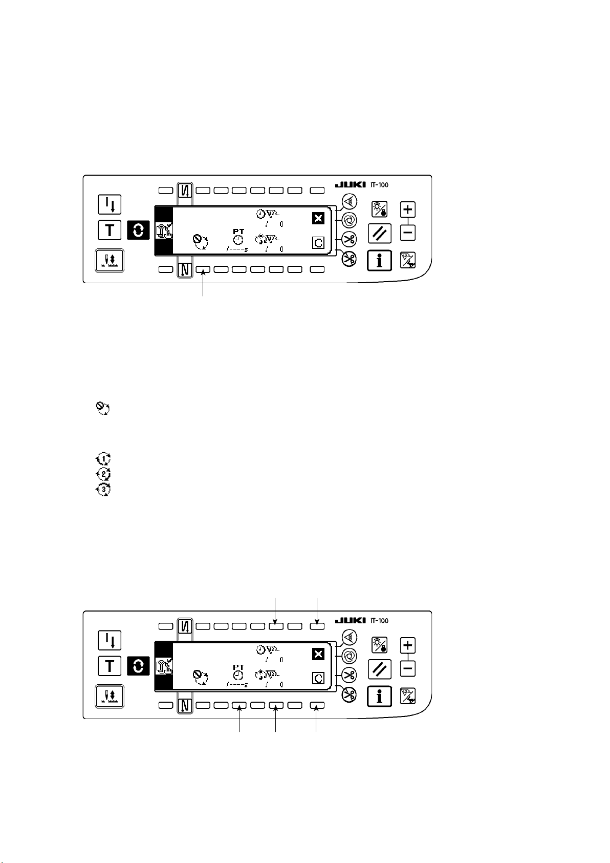
<Production management function setting screen>
The production management function screen displays the target production volume for given working hours
and the actual number of sewn products to notify the operator of a delay or progress of his/her sewing work
in real time.
The target production volume is calculated in two different methods. The method can be changed over using
switch 1 for setting the target production volume count-up method.
1
: Counting up according to the target pitch time
"@. 2-2. Displays on the screen for the production support function"
1
Counting up the target production volume according to the lapse of a specied pitch time
for the operating pro-
Calculating the target production volume as of the current time of day according to the specied
2
starting/nishing times of day of work and total production volume
: Calculating from the working time of day 1
: Calculating from the working time of day 2
: Calculating from the working time of day 3
(4)-1 In the case of counting up the target production volume according to the pitch time
The target production volume is counted up according to the lapse of a specied target pitch time.
<Production management function setting screen (in the case of count-up according to the pitch time>
4
6
2 3 5
Input data on items 2 to 4 referring to the table given in the next item.
When Screen closing switch 6 is pressed, the screen is closed and restored to the previous screen.
When Clear switch 5 is pressed, the target pitch time, target production volume for a day and the current
target production volume can be totally cleared.
– 13 –
Page 17
No. Item to be set Description
Target pitch time setting
❷
switch
Daily target production
❸
volume setting switch
Current target production
❹
volume correction switch
The target pitch time for sewing work is set. Every time the length of time corre-
sponding to the target pitch time is elapsed, the current target production volume
is counted up.
* When the switch is pressed, the numeric input popup screen is displayed. Input
a set value in the popup screen.
* When the target pitch time is changed, the current target production volume
is automatically cleared.
The target production volume to be produced from the starting to the end of
working hours in a day is set.
* When the switch is pressed, the numeric input popup screen is displayed. Input
a set value in the popup screen.
The current target production volume that is counted up every time the length of
time corresponding to the target pitch time is elapsed can be corrected.
* When the switch is pressed, the numeric input popup screen is displayed. Input
a corrected value in the popup screen.
❹
(4)-2Inthecaseofcalculatingthetargetproductionvolumeaccordingtothespeciedstarting/n-
ishing times of day of work and total production volume
The target production volume as of the current time of day is calculated and displayed on the production management screen under the sewing mode by setting data on the time period during which sewing work is carried
out such as the starting/nishing/resting times of day and a daily target production volume.
* Three different working conditions to can be entered. When two or more operators use one sew-
ing machine, the machine should be used after the entry of working hours on an operator-by-operator
basis.
<Production management function setting screen (in the case of calculating the target production
volumebysettingthestarting/nishingtimesofdayandthetotalproductionvolume)>
❼ ❽ ❾
Input data on items ❼ to ❾ referring to the table given in the next item.
When
Screen closing switch
When
Clear switch
is pressed, the operating time and rest time and the daily target production volume of
the selected working conditions
is pressed, the screen is closed and restored to the previous screen.
to can be totally cleared.
– 14 –
Page 18
No. Item to be set Description
Working condition selec-
❼
tor switch
Working/resting times
❽
setting switch
Daily target production
❾
volume setting switch
①
. How to set the working time and resting time
On the assumption that one sewing machine is used by the operators working
the shift or for sewing two or more different sewing items, three different daily
working conditions (working hours and total production volume)
be set. The working conditions set in this step can be invoked on the production
management screen under the normal sewing mode. This eliminates re-setting
of detailed working conditions at the shift time or the sewing item changing.
The starting/nishing times of work and the resting time of day are set. The working time period can be set more nely with working time and resting time each of
which can be set to three different values.
Refer to the next item "① How to set the working time and resting time"
→
for details of setting procedure.
The actual working time, obtained by subtracting the resting time from the
*
length of time elapsed from the starting to the end of daily work, is disp
The target production volume to be produced from the starting to the end of
working hours in a day is set.
*
When the switch is pressed, the numeric input popup screen is displayed. Input
a set value in the popup screen.
can
layed.
Daily working time is set nely by the working time and resting time each of which can be set to three dif-
ferent values.
The following shows an example of the setting procedure. Input data appropriately referring to the exam-
ple.
Example) Set the following time period for working condition
Working hours : 8:00 - 17:00
8:00
10:00
.
12:00 13:00
15:00
17:00
Lunch break : 12:00 - 13:00
Work break s : 10:00 - 10:10, 15:00 - 15:10
<Setting procedure>
1) Start setting the working time and
resting time
Start inputting data on working condi-
Working/resting times setting
tion
❶
.
Input of data on working time 1
2) Set the working time.
Select the input of working time 1
. Input of data on working time 1
❷
– 15 –
Page 19
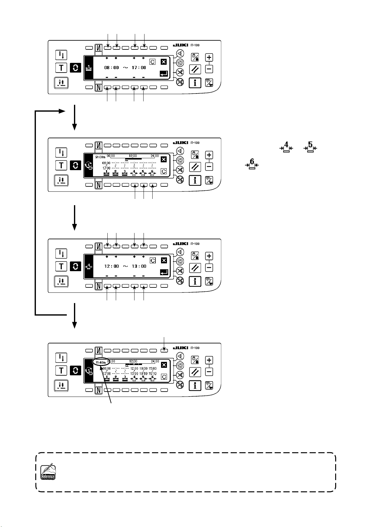
Input of working hours
3
3) Input the working hours 8:00 to
17:00.
Input of working hours
Input of resting times 4, 5 and 6
Input of a work break
3
5
4) Set the resting time
Select the input of data on rest-
ing times 4 , 5 and 6
.
4
5) Input the lunch break 12:00 to
13:00.
Input the work break 10:00 to
10:10.
Input the work break 15:00 to
15:10.
Input of a work break
A
5
Setting is completed
6
6) Setting is completed.
* Section A displays the actual working hours obtained by subtracting the resting time from the length of
time elapsed from the starting to the end of daily work.
It is possible to load the data edited by means of the IA-1 as the working hours setting data.
In the case of using a USB thumb drive, turn the power ON with a medium registered in a given
folder inserted, the data on the medium will be automatically loaded onto the personal computer.
The working hours data cannot be output from the IT-100.
– 16 –
Page 20
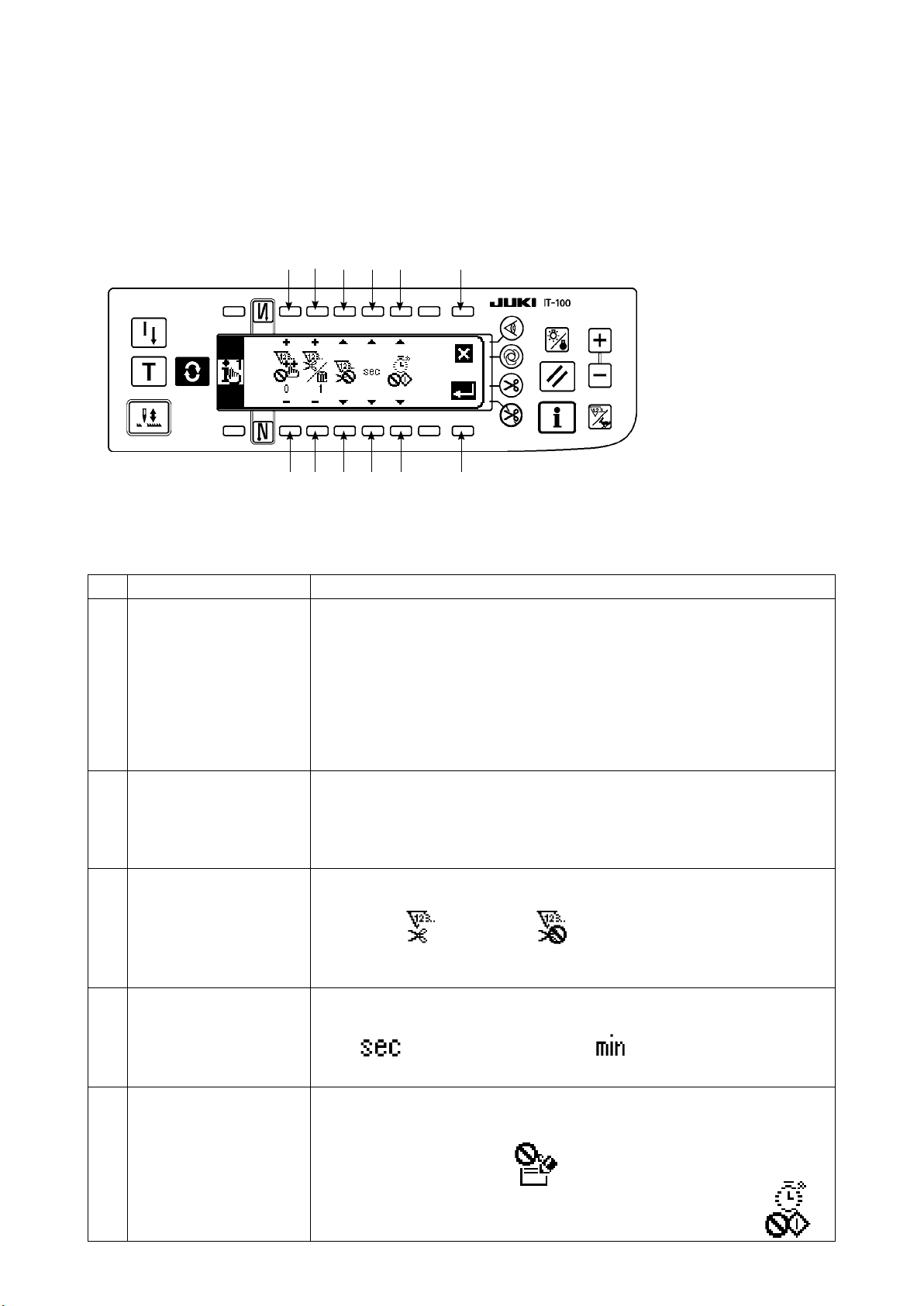
(5) Setting common data for the production support function
* Refer to
"@. 2-2. Displays on the screen for the production support function"
for the operating pro-
cedure to be taken until this screen is displayed.
Items commonly applied to each production support function are set on the production support common set-
ting screens No. 1 and No. 2.
(5)-1 Production support common setting screen No. 1
1
1
2
2
3
3
4
5
4
5 6
7
Input data on items 1 to 5 referring to the table given below.
When Enter switch 6 is pressed, the input data is conrmed. When Cancel switch 7 is pressed, the in-
put data is cancelled and the screen is restored to the previous screen.
No. Item to be set Description
Acceptable num b e r of
1
stitches for count-up
Th e nu m b e r of ti m e s
2
of thr e ad trimmi n g per
count
Enable/disable of count
3
by thread trimming
Display method selector
4
switch
When the sewing machine stops after thread trimming and the number of sewn
stitches exceeds the preset number of stitches, an input of the count-up of production volume is accepted.
Setting range : 0 - 99 Initial value : 0
* Input of the production volume count-up :
Production volume count-up switch and the optional production management
switch input, displayed on each production support screen under the normal sewing mode.
This setting is used for preventing incorrect input or fraudulent input.
The number of times of thread trimming per count on the production volume
counter is set.
Setting range : 1 - 999 Initial value : 1
* This setting is used in the case of automatic count up by the thread trimming
operation without using the production volume counter.
Enable/disable of the automatic count-up of the production volume counter and
the quantity of sewn items counter.
Enable Disable Initial setting : Disable
* When this item is set to the enable, the number of times of thread trimming de-
scribed in 2 is referred.
The unit employed to display the time data on each production support function
screen is set.
: Displayed in second : Displayed in minute
Initial setting : Displayed in second
Resting status On each production support function screen, the measurement of the operational
5
status of the sewing machine and recording of data can be temporarily halted.
This halt status is set.
Measurement is at halt :
Measurement is at halt and starting of the sewing machine is prohibited :
– 17 –
Page 21
(5)-2 ISS setting screen
* Refer to
"@. 2-2. Displays on the screen for the production support function"
cedure to be taken until this screen is displayed.
1
1
6
5
Input the item to be set referring to the table.
When Enter switch
is pressed, the input data is conrmed. When Cancel switch
5
data is cancelled and the screen is restored to the previous screen.
No. Item to be set Description
Setting the function for
1
automatically uploading
ISS data on the network
Changes over the enable/disable of automatic uploading of the ISS data on the
network
for the operating pro-
is pressed, the input
6
– 18 –
Page 22
. OPERATION
Ⅲ
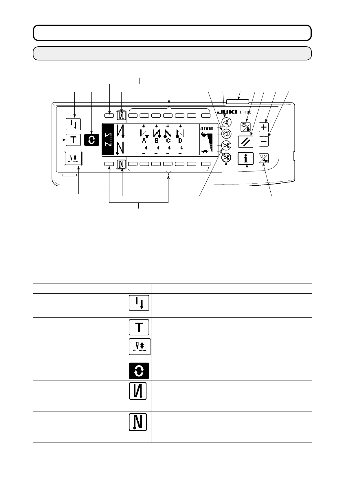
1. CONFIGURATION OF THE OPERATION PANEL
❶ ❹ ❺
❷
❸
Re-sewing switch
❶
Teaching switch
❷
Needle up/down compensating
❸
switch
Screen changeover switch
❹
With/without reverse feed stitch at
❺
sewing start switch
With/without reverse feed stitch at
❻
sewing end switch
❻
Material edge sensor switch
❼
One-shot automatic sewing
❽
switch
With/without automatic thread trim-
❾
mer switch
Thread trimming prohibiting
switch
Backlight switch
❾
❽
❼
Reset switch
Information switch
+ switch
- switch
Counter/speed changeover switch
General-purpose switch
Power display lamp
Switch Description
Re-sewing switch
❶
Teaching switch
❷
Needle up/down compensat-
ing switch
❸
Screen changeover
❹
With/without reverse feed
stitch at sewing start switch
❺
With/without reverse feed
stitch at sewing end switch
❻
switch
This switch is used to continue sewing from the step on the way
after replacing bobbin thread when bobbin thread has run out
during program stitching step.
This is the switch to set the setting of the number of stitches with
the value of number of stitches which has been actually sewn.
This is the switch to perform needle up/down compensating stitching.
(Needle up/down compensating stitching and one stitch compensating
stitching can be changed over with function setting No. 22.)
This is the switch to change over the screen.
This is the switch to turn ON/OFF automatic reverse feed stitch at
sewing start.
* This switch cannot be used with the sewing machine which is
not provided with automatic reverse feed stitching device.
This is the switch to turn ON/OFF automatic reverse feed stitch at
sewing end.
* This switch cannot be used with the sewing machine which is
not provided with automatic reverse feed stitching device.
– 19 –
Page 23
Edge sensor switch
❼
Switch Description
Selects use/disuse of the material edge sensor in the case the
material edge sensor (edge) is installed on the sewing machine
One-shot automatic sewing
switch
❽
With/without automatic thread
trimmer switch
❾
Thread trimming prohibiting
switch
Backlight switch
Reset switch
Information switch
Plus switch
Minus switch
When this switch is pressed, the sewing machine automatically
operates until the material edge sensor detects the material edge
or until the set number of stitches is reached.
This switch is used to automatically trim the thread when the material edge sensor detects the material edge or until the set number of stitches is reached.
* This switch cannot be used with the sewing machine which is not
provided with the automatic thread trimming device.
This switch prohibits all thread trimmings.
* This switch cannot be used with the sewing machine which is not
provided with the automatic thread trimming device.
This switch is used to change over the operation of the backlight
of the LCD between ON and OFF.
This is the switch to make the value of bobbin thread counter or
sewing counter the set value. This switch is enabled after thread
trimming.
This switch is used to change over the screen between the in-
formation function screen (sewing common data mode, function
setting mode, communication mode, version display, etc.) and the
normal sewing screen.
This switch is enabled after thread trimming.
This switch is used to increase the set value of the bobbin thread
counter or the number of pcs. counter at the time of setting. It
should be remembered that this switch is enabled after thread
trimming.
This switch is used to decrease the set value of the bobbin thread
counter or the number of pcs. counter at the time of setting. It
should be remembered that this switch is enabled after thread
trimming.
Counter/speed changeover
switch
General-purpose switch This switch has different functions depending on the screen.
Power display lamp This lamp lights up when the power switch is turned ON.
This switch is used to change over the display between the count-
er display and the maximum sewing speed limitation display.
– 20 –
Page 24
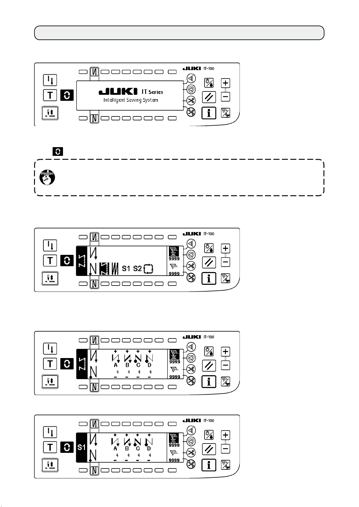
2. SEWING SCREEN
When you turn ON the power to the IT-100 panel, the welcome screen will appear.
The screen which appears immediately after the welcome screen is the one which has been selected imme-
diately before the power is turned OFF. Then, the screen is changed over every time the screen changeover
switch
Typeandscreenconguration of the normal sewingmodevaryaccordingtothemodel of the
Refer to "#-3. HOW TO OPERATE THE SEWING PATTERN" for the operation procedure to be
is pressed.
sewing machine.
taken on each screen.
Pattern list screen
■
Selection of the respective shapes is performed.
Number of stitches of back tuck stitching setting screen
■
Setting of number of stitches of reverse stitching is performed.
When reverse stitching pattern is selected
<
>
When programmed stitching pattern 1 is selected
<
>
– 21 –
Page 25

– 22 –
Numberofstitchesofoverlappedstitchingsettingscreen
■
Setting of number of stitches of overlapped stitching is performed.
Programmed stitching setting screen
■
Setting of the respective conditions of programmed stitching is performed.
When programmed stitching pattern 1 is selected
<
>
Cycle sewing setting screen
■
Setting of the step of cycle sewing is performed.
Cycle sewing pattern setting pop-up
■
Setting of the pattern of cycle sewing is performed.
Page 26
Work management screen
■
On this screen, the contents of display related to the production support function and those called up by
operating the switches can be set or changed.
When the production support function is enabled under the information mode, the respective
production support function screens can be displayed by means of the screen changeover
switch from the work management screen. Refer to "@-2-2. Displays on the screen for the
production support function" for details.
– 23 –
Page 27

– 24 –
3. HOW TO OPERATE A SEWING PATTERN
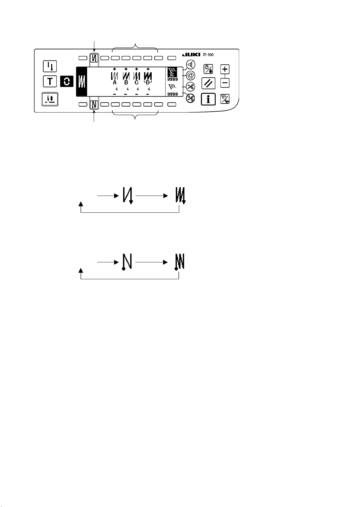
3-1. Reversestitchingpattern
2
OFF ON ON
OFF
Sewing
pattern
3
A
B
OFF OFF
C
D
ON ON
A
B
C
D
Press the screen changeover switch to display the pattern list screen.
1
1) Press switch
to select the reverse stitching pattern, and the screen is automatically changed over to
1
the number of stitches of reverse stitching setting screen to display the number of stitches which has
already been set.
Page 28
2
4
3
2) When changing the number of stitches, change it with switches
5
and 5 for setting the number of stitch-
4
es A through D.
(The range of the number of stitches that can be changed : 0 to 99 stitches)
3) Press switch
No setting Reverse stitching
4) Press switch
No setting Reverse stitching
to set the reverse stitching at the start of sewing.
2
Double reverse stitching
at the start of sewing
to set the reverse stitching at the end of sewing.
3
at the end of sewing
at the start of sewing
Double reverse stitching
at the end of sewing
– 25 –
Page 29

– 26 –
3-2. Overlappedstitchingpattern
A C C
B B
D
Press
1) Press switch 1 to select the overlapped stitching pattern, and the screen is automatically changed over
to display the pattern list screen.
1
to the number of stitches of overlapped stitching setting screen to display the number of stitches which
has already been set.
2
4
3
2) When changing the number of stitches, change it with switches 2 and 3 for setting the number of stitch-
es for processes A through C. To change the number of times of the whole processes, change it with
switches 4 and 5 for setting the number of processes D.
(The range of the number of stitches A, B and C that can be changed : 0 to 19 stitches. The range of the
number of processes D that can be changed : 0 to 9 times)
3) Depress the front part of the pedal once, and the sewing machine will repeat the normal stitching and
reverse stitching as many as the number of specied times. Then the sewing machine will automatically
make the thread trimmer actuate and will stop to complete the overlapped stitching procedure. (The one-
shot automatic stitching cannot be turned OFF.)
4) When thread trimming prohibiting function 6 is selected, the machine will stop with the needle up upon
completion of the overlapped stitching procedure without performing thread trimming.
5
6
Page 30

3-3. Programmed stitching pattern
The constant-dimension stitching process can be programmed as many as 20 operation steps. The sewing
conditions including the number of stitches, needle up/down stop mode, automatic thread trimming, con-
tinuous operation steps, lifting/lowering of presser foot and normal/reverse feed stitching can be separately
specied for the respective operation steps. If the lifting of presser foot is specied, the time during which
the presser foot is raised can be also specied.
Example of programmed stitching pattern
4
Step 4
4
4
4
20 20
10
Step 3Step 1
10
Step 2
Press to display the pattern list screen.
Programming procedure is described below tak-
ing the pattern on the left side as an example.
1
1) Press switch 1 to select the programmed stitching pattern, and the screen is automatically changed over
to the programmed stitching setting screen to display the number of stitches and data on the operation
step 1 which have already been specied.
– 27 –
Page 31

– 28 –
[Step 1]
2 4 6
3 5 7 9
1) Conrmthatstep1isdisplayedonthepanel.Now,setthenumberofstitchesto20usingswitches2and
2) Setthefeedingdirectiontothenormaldirectionusingswitches4and
3) Setthestopstateofthesewingmachinetotheneedle-downstopmodeusingswitches6and
If the number of stitches is set to 0 stitch or the stop-state of the sewing machine is set to the
automatic thread trimming mode , the machine will not proceed to the subsequent operation step.
8
!0
!1
5
3
.
.
7
4) Setthepositionofthepresserfoot,whenthesewingmachinestops,totheupperstoppositionusing
switches8and9.
(Ifyouwanttospecify,Inparticular,thelengthoftimeduringwhichthepresserfootIsraised,setItas
desiredusingswitches!0and!1.IntheInitialstate,thelengthoftimeIs60seconds.Possiblesetting
rangeofthetimeduringwhichthepresserfootIsraised:0.1sec.to99.9sec.)
.
Settings done by switches 8, 9, !0 and !1 are only available under the setting where the auto-
lifter can be used (i.e., FL ON).
[Step 2]
!2
2
3
5) Pressswitch!2oncetodisplaystep2.
6) Setthenumberofstitchesto10usingswitches2and3.
Page 32

[Step 3]
!2
2
3
7) Set the feeding direction to the normal direction, the stop-state of the sewing machine to the needle-
down stop mode and the position of the presser foot to the upper stop position as in the case of step 1.
8) Press switch
9) Set the number of stitches to 20 using switches
10) Set the feeding direction to the normal direction, the stop state of the sewing machine to the needle-
down stop mode and the position of the presser foot to the upper stop position as in the case of steps 1
and 2.
[Step 4]
once to display step 3.
!2
and 3.
2
!2
!3
!4
11) Press switch
12) Set the number of stitches to 10 using switches
13) Set the feeding direction to the normal direction using switches
14) Set the stop state of the sewing machine to the automatic thread trimming mode using switches 6
and 7.
15) Set the position of the presser foot, when the sewing machine stops, to the upper stop position using
switches 8 and 9.
16) Select the reverse stitching using switches
17) It is also possible to specify the double reverse stitching using switches
once to display step 4.
!2
2 4 6 8
3 5 7 9
and 3.
2
and 5.
4
and !4. This completes the data setting procedure.
!3
and !4.
!3
Every time each step is nished, operate the touch-back switch, and the sewing machine runs at a low speed
(stitch compensation operation).
You can program another sewing processes in the programmed stitching pattern 2 following the aforemen-
tioned procedure.
In case of pattern 2, the display on the left end of the screen becomes
When switch is pressed in the programmed stitching setting screen, the screen is changed over to the
number of stitches of reverse stitching screen and the number of stitches of reverse stitching at the time of
programmed stitching can be set. The number of stitches of reverse stitching can be separately set for pat-
terns 1 and 2.
– 29 –
.
Page 33

– 30 –
Teaching mode
<
>
In the teaching mode, it is possible to set the number of stitches of the step in a programmed stitching pat-
tern to the number of stitches that has been actually sewn.
2
1
1) In the programmed stitching setting screen, press teaching switch 1 to select the teaching mode.
2) The indication shown on the number of stitches input section changes to . This shows that the sewing
machine has entered the teaching mode.
3) Depress the front part of the pedal to make the sewing machine perform sewing until the last stitch of the
current operation step is reached.
The number of stitches is not counted for the stitch sewn by manually turning the sewing ma-
chine or using the needle up/down switch.
4) Return the pedal to its neutral position to make the sewing machine stop running. Now, the number of
stitches which has been sewn is displayed.
5) Proceed to the subsequent step using switch 2 or make the sewing machine perform thread trimming.
This completes the input of the number of stitches for operation step 1.
One-shot automatic stitching
<
>
The one-shot automatic stitching function can be separately set by steps.
1
1) In the programmed stitching pattern setting screen, press one-shot automatic stitching switch 1 to select
the one-shot automatic stitching function.
2) A mark is displayed on LCD section of the switch, which shows the one-shot automatic stitching function
has been selected.
3) In the step where the one-shot automatic stitching function has been selected, the sewing machine
will automatically continue sewing, once the sewing machine starts running, until the end of the step is
reached.
Page 34

Continuous stitching mode
<
In this mode, it is possible to make the sewing machine execute the subsequent step after the completion of
the current step.
1) In the programmed stitching pattern setting screen, select the continuous stitching mode using switches
and 2.
1
2) As long as the continuous stitching mode is selected, you can make the sewing machine execute the
subsequent step set in the program after the completion of the current step by depressing the front part
of the pedal.
To operate the operation panel in combination with the material edge sensor
<
• When the operation panel is used in combination with the material edge sensor, the sewing process can
be completed not by the predetermined number of stitches but by the input signal of the material edge
sensor.
• Carefully read the Instruction Manual for the material edge sensor before using the sensor with the
operation panel.
>
1
2
>
3-4. Cycle sewing pattern
Reverse stitching pattern, overlapped stitching pattern, programmed stitching pattern 1 and programmed
stitching pattern 2 can be set and sewn as desired. (As many as eight different patterns can be set.)
1
1) Press switch 1 to display the cycle sewing edit pattern setting pop-up.
– 31 –
Page 35

– 32 –
2
4 6 8
!0 !2
!1
Switches
Switches
Switches
Switches
Switches
2
4
6
8
!0
and
and
and
and
and
5 7 9
3
: These switches set the reverse stitching pattern.
3
: These switches set the overlapped stitching pattern.
5
: These switches set the programmed stitching pattern 1.
7
: These switches set the programmed stitching pattern 2.
9
: These switches delete the editing step.
!1
Switch !2 : The screen returns to the cycle sewing setting screen.
[Example of setting]
2) Every time the thread trimmer actuates, the machine proceeds to the subsequent pattern which has been
selected. (The step which is being executed is shown in reverse video during execution.)
If the thread trimmer actuates before completion of a pattern, the machine will proceed to the
subsequent program.
Page 36

4. HOW TO OPERATE THE COMMON FUNCTIONS
The common functions are operated in the same way regardless of the model of sewing machine. (The
screen display varies depending on the model of sewing machine.)
4-1. Bobbin counter
The number of stitches sewn by the sewing machine is detected. The detected number of stitches is decremented from the
preset counter value (in units of the number of stitches preset using function setting No. 7 "Unit of bobbin thread counting
down." When the counter value changes from the positive value to the negative value (...→ 1 → 0 → -1), the buzzer sounds (3
sets of two consecutive blips) and the notication is shown on the popup window to alert the operator to change the bobbin.
2
3
4
5
1) Press counter/speed changeover switch
change over the screen to the counter screen.
Press switch 2 to select the bobbin counter. Then,
press counter reset switch 3 to return the bobbin
counter display to the initial set value (set value at
the time of delivery is "0").
The bobbin thread counter cannot be reset during sewing. In this case, make the
thread trimmer actuate once.
1
to
1
Initial value on the bobbin thread counter
for reference
3) Once the initial value is specied, start the sewing machine.
4) When a minus value is shown on the counter,
the buzzer peeps three times and the pop-up
display appears, replace the bobbin thread.
2) Set an initial value using counter value setting
switches
and 5.
4
The table below gives the initial setting values for reference when the bobbin is wound with thread to the extent that the pinhole in the outside of the bobbin case is
reached as shown in the gure on the left side.
Thread
used
Polyester spun
thread #50
Cotton thread #50
Length of thread wound
round the bobbin
36 m 1200
31 m 1000
Value on bobbin
thread counter
(stitch length : 3 mm)
(stitch length : 3 mm)
Thread tension rate 100 %
* The aforementioned values actually vary depending on
the material thickness and sewing speed. Adjustment is
necessary according to the conditions of use.
Bobbin thread replacement warning pop-up
5) After the bobbin thread has been properly replaced, press counter reset switch 3 to return the value on
the bobbin thread counter to the initial value. Now, re-start the sewing machine.
6) If the remaining amount of bobbin thread is excessive or the bobbin thread runs out before the bobbin
thread counter indicates a minus value, adjust the initial value appropriately using counter value setting
switches 4 and 5.
If the remaining amount of bobbin thread is excessive ..... Increase the initial value using the “+” switch.
If the remaining amount of bobbin thread is insufcient .... Decrease the initial value using “–” switch.
1. The remaining amount of thread may vary depending on how the thread is wound on the bobbin and the material thickness. It is therefore better to set the remaining amount of thread
with a slight allowance.
2. If the bobbin thread counter is used in combination with the bobbin thread remaining amount
detecting device, the bobbin thread counter indicates the number of detections of the bobbin
thread remaining amount detecting device. So, be sure to use the device after carefully reading the Instruction Manual for the bobbin thread remaining amount detecting device.
– 33 –
Page 37

– 34 –
4-2. Setting the maximum sewing speed
Set the maximum sewing speed.
2
Press counter/speed changeover switch
over the screen to the maximum sewing speed setting
screen. Press switch
4
5
1
3
speed, or switch
of 50 sti/min)
3
1
or
to increase the sewing
4
to decrease it. (In increments
or
2
5
to change
4-3. Setting the backlight
Change over the backlight between ON and OFF.
1
When press backlight switch 1 while the backlight is in
the off state, it will light up. When you press the switch
while the backlight is in the on state, it will go out.
The IT-100 has adopted a semi-transmis-
sion liquid crystal display. It is therefore
necessary to turn on the backlight in the
dark. In the light, the display reduces power
consumption by utilizing the reflection of
outside light.
Page 38

4-4. Re-sewing switch
The re-sewing switch is used when the bobbin thread runs out during the programmed stitching pattern sewing steps or the like.
1) The bobbin thread runs out during the operations
1
D
C
Step 4
B
A
Step 3Step 1
d
a
e
b
c
steps for sewing.
a
2) Bring the pedal to its neutral position to make the
sewing machine stop. Now, depress the back part
of the pedal to make the thread trimmer actuate.
3) Turn ON re-sewing switch
1. c
4) Replace the bobbin. Slightly feed the material on
the machine in the reverse direction to return the
material to the position where the sewing was interrupted to allow the sewing machine to sew over the
nished seam in step 2. d
5) Depress the front part of the pedal until stop position e of step 2 is reached.
6)
Turn ON re-sewing switch e again at position
1
where the sewing has been interrupted, and the next
step will be indicated on the operation panel. Now,
you can re-start sewing of the programmed stitching
pattern.
*
If the needle thread breaks or any other trouble occurs, which is caused by re-sewing switch 1 during the operation steps (d → e) in the free sewing
mode, bring the pedal to its neutral position, Then
depress the back part of the pedal to actuate the
thread trimmer. Thread the machine head and slightly
feed the material in the reverse direction, and press
re-sewing switch 1. This enables the sewing machine
to continue the sewing under the free sewing mode.
Then operate the operation panel as described in the
aforementioned steps 5) and 6).
b
To r et u r n t o t h e f ir s t st ep o f t he p r o -
4-5. Needle up/down compensation switch
Every t i me nee d l e up/d o wn comp e nsatio n switch 1 is
pressed, the needle goes up when it is in its lowest position
or comes down when it is in its highest position. This compensates the stitch by a half of the predetermined stitch length.
1
Note, however, that the machine does not run continuously at
a low speed even if you keep the switch held pressed.
Also, note that the needle up/down compensation switch is inoperative after turning the handwheel by hand.
Thread trimming is operative only at the time of stitch compensation after depressing the front part of the pedal once.
grammed stitching pattern without using
re-sewing switch 1, depress the back part
of the pedal to actuate the thread trimmer.
This makes the operation panel give the
step indication 1. Now, you can start sewing from the first step of the programmed
stitching pattern.
– 35 –
Page 39
– 36 –
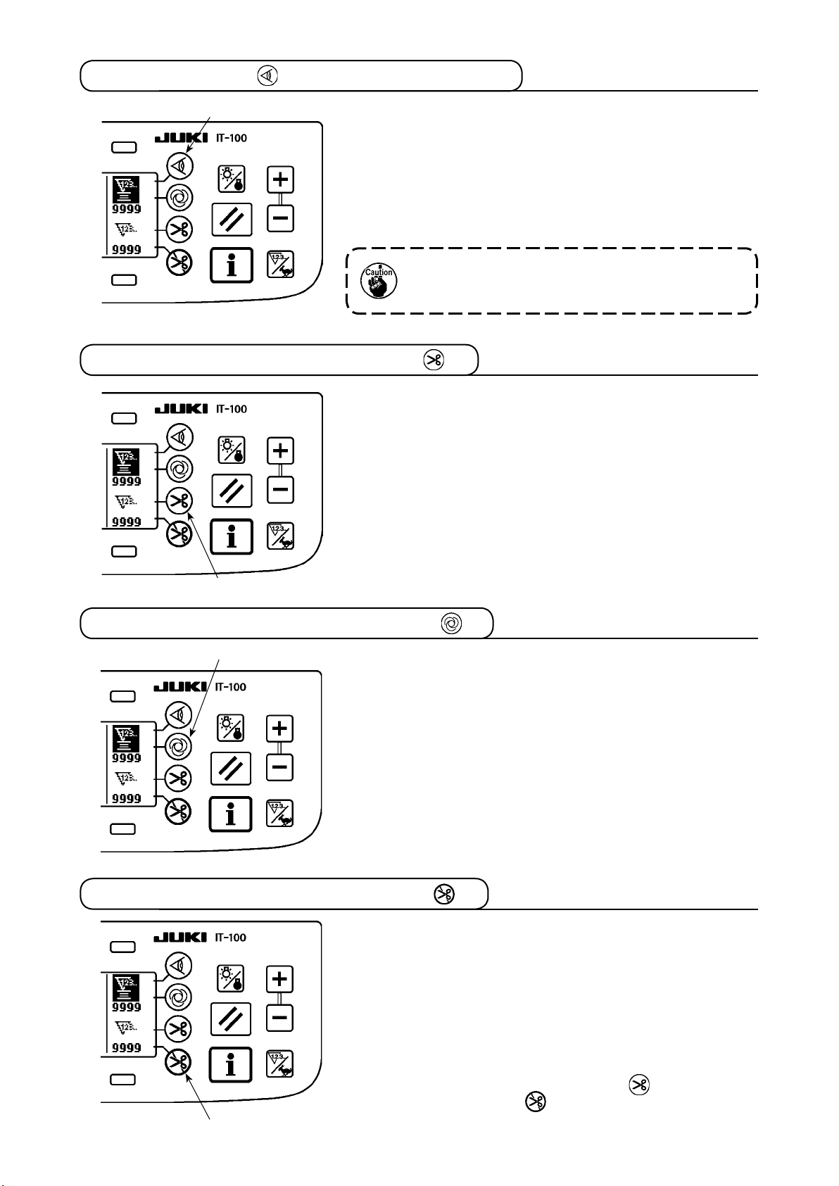
4-6. On/off switch of the material edge sensor
1
• When material edge sensor 1 is pressed, ON/OFF of the
material edge sensor is changed over.
• When the material edge sensor, which is optionally available,
is connected to the operation panel, the ON/OFF switch of the
material edge sensor becomes effective.
• If the material edge sensor is specied, the sewing machine will
automatically stop running or perform thread trimming when the
sensor detects the material edge.
If the material edge sensor is used in combination
with the operation panel, carefully read the Instruc-
tion Manual for the material edge sensor beforehand.
4-7. Automatic thread trimming switch
• When automatic thread trimming switch 1 is pressed, ON/OFF
of the automatic thread trimming is changed over.
• This switch i s re n d ered effective, when t h e ma t erial end
sensor is turned ON for the reverse feed stitching pattern, to
automatically activate the thread trimmer upon detection of the
material end.
(if the automatic reverse stitching (for end) is specified, the
thread trimmer will actuate after the sewing machine completes
the automatic reverse stitching (for end).)
1
4-8. One-shot automatic stitching switch
1
• When one-shot automatic stitching switch 1 is pressed, ON/
OFF of the one-shot automatic stitching is changed over.
• This switch is used, in the constant-dimension stitching mode,
rectan g ular s t itchin g mode, o r in t h e proc e s s whe r e the
material edge sensor is specied, to make the sewing machine
automatic ally perform sewing at th e specifie d speed until
the end of the process is reached only by driving the sewing
machine once.
4-9. Thread trimming prohibition switch
• When thread trimming prohibition switch 1 is pressed, ON/OFF
of the thread trimming prohibition is changed over.
• This switch is used to temporarily make the thread trimming
function inoperative.
The other performance of sewing machine is not affected by this
switch.
(If the automatic reverse stitching (for end) is specied, the sewing
machine will perform the automatic reverse stitching at the end of
sewing.)
• If the automatic th read trimming switch a n d t h e t h r e ad
trimming prohibition switch are both specified, the machine
1
will not perform thread trimming but stop with its needle up.
Page 40

4-10. Simpliedfunctionsetting
WARNING :
If the solenoid is used under the air drive mode, the solenoid can burn out. Be sure to carefully avoid
thewrongsettingofthepresserfootliftingdevicespecication.
Function setting items can be simplied in part.
[Simpliedfunctionsettingscreen]
642
1) Keeping thread trimming prohibiting switch
1
held pressed, turn the power ON. Then, the
screen is changed over to the simplied function setting screen. The details displayed on
the screen represent the current settings.
2) Function items can be changed by pressing
3 1
5 7
Wiper function (WiP): Switches 2 and
■
8
switches
3
and 3, 4 and 5 or 6 and 7.
2
This function activates the wiper.
oFF : The wiper does not operate after thread trimming.: The wiper does not operate after thread trimming.The wiper does not operate after thread trimming.
on : The w: The wThe wiper operates after thread trimming (standard setting at the time of delivery)
Auto-lifter (FL): Switches 4 and
■
5
This function activates the auto-lifter function when the presser foot lifting device (AK) is installed on the
sewing machine.
For the presser foot lifting device specications, solenoid drive mode (+33 V) or air drive mode (+24 V)
can be selected.
The drive source voltage (CN37) is changed over between +33 V and + 24 V according to the drive
mode specication selection.
oFF : Auto-lifter does not operate. (standard setting at the time of delivery): Auto-lifter does not operate. (standard setting at the time of delivery) Auto-lifter does not operate. (standard setting at the time of delivery)
(The presser foot does not automatically go up when the program sewing is completed.)
on S : Auto-lifter operates. (Solenoid drive mode [+33 V]): Auto-lifter operates. (Solenoid drive mode [+33 V]) Auto-lifter operates. (Solenoid drive mode [+33 V])
on A : Auto-lifter operates. (Air drive mode [+24 V]): Auto-lifter operates. (Air drive mode [+24 V]) Auto-lifter operates. (Air drive mode [+24 V])
Needle position changeover function for the time when the sewing machine stops (nP) :
■
Switches 6 and
7
The needle position at the time when the sewing machine stops can be changed over.
Lo : Lower stop position (standard setting at the time of delivery): Lower stop position (standard setting at the time of delivery) Lower stop position (standard setting at the time of delivery)
UP : Upper stop position: Upper stop position Upper stop position
3) Once you have completed the setting, press switch 8. The screen is changed over to the power switch
OFF notication screen.
[PowerswitchOFFnoticationscreen]
4) Turn OFF the power switch to exit from the
simplied function setting.
If "on" (auto-lifter operates) is selected without the auto-lifter installed, the machine startup is
momentarily delayed at the beginning of sewing. In addition, the one-touch type reverse feed
(touch-back) switch may be disabled. To avoid these troubles, be sure to select "oFF" (auto-lifter
does not operate) when the auto-lifter device is not installed.
– 37 –
Page 41

– 38 –
4-11. Key-lock function setting
In order to prevent settings of the number of stitches or detailed settings for processes (A, B, C and D), it is
possible to lock the function setting switches in the current state. (Even under the key-lock mode, the pat-
terns or bobbin counter can be changed.)
[Key-lock function setting screen]
3
4 5
1
2
1) Keeping thread trimming prohibiting switch
and counter value setting switch (+)
2
simultaneously, turn the power ON. Then, the
screen is changed over to the key-lock func-
tion setting screen. Setting displayed on the
screen represents the current setting of the
key-lock function.
2) The key-lock function can be changed over
between "on" (key-lock function is effective)
and "oFF" (key-lock function is ineffective
[standard setting at the time of delivery]) by
pressing switches
and 4.
3
3) Once you have completed the setting, press
switch 5. The screen is changed over to the
power switch OFF notication screen.
1
held
[PowerswitchOFFnoticationscreen]
4) Turn OFF the power switch to exit from the
simplied function setting.
[Number of reverse feed stitches setting screen] (Example of display)
6
5) When the key-lock function is "on" (key-lock
function is effective), key icon 6 is displayed
on the screen.
Page 42

4-12. Function setting
Functions of the sewing machine can be programmed and the number of stitches and the sewing speed can
be changed.
Refer to the Instruction Manual for the SC-920 for how to change the function setting items and for the details
of the functions.
[Function settings list screen]
1) Keeping switch
power ON. Then the screen is changed over
to the function settings list screen.
When you press switch 2, the screen is
changed over to the function setting display
screen.
held pressed, turn the
1
[Function setting display screen]
F u n c t i o n
setting No.
3
4 5
[Function setting popup screen]
6
7
Set value
8
12
The function setting list screen can be
displayed from the information screen
(maintenance personnel level). Refer
to "$-2. MAINTENANCE PERSONNEL
LEVEL".
2) Function setting item number can be incremented or decremented by pressing switches
and 4.
3
3) Once you have determined the target function
setting number, press switch
. The screen
5
is changed over to the function setting popup
screen.
4) Function setting item number can be incremented or decremented by pressing switches
and 7.
6
5) Once you have completed set value changing,
press switch 8. The screen is changed over
to the function setting display screen and the
changed set value is displayed on the screen.
6) Turn OFF the power switch to exit from the
function setting.
* To change two or more different function
setting numbers, repeat the aforementioned
steps of procedure 2) through 5) as required.
Example) [To change the number of stitches 0 to 3 using the soft-start function (function setting No. 1)]
[Function setting display screen]
3
1) Press switches
3
and
to select function
4
setting No. 1.
2) Press switch 5. The screen is changed over
to the function setting popup screen.
4 5
– 39 –
Page 43

– 40 –
[Function setting popup screen]
6
7
[Function setting display screen]
8
3) Press switches
and 7 to change the set
6
value to 3.
4) Press switch 8. The screen is changed over
to the function setting display screen.
5) The changed set value is displayed on the
function setting display screen.
6) Turn OFF the power switch to exit from the
function setting.
Refer to the Instruction Manual for the SC-920 for the function setting list and the details of the
function setting items.
Page 44

Function setting list
No.
1 Soft start function The number of stitches to be sewn at a low speed when the soft-
2 Material end sensor
3
4 Number of stitches
5 Flicker reducing
6 Bobbin thread
7 Unit of bobbin
*
8 Sewing speed
*
9 Thread trimming
Item Description
start function is used at the start of sewing.
0 : The function is not selected.
1 to 9 : The number of stitches to be sewn under the soft-start
mode.
function
Thread trimming
function by material
end sensor
for material end
sensor
function
counting function
thread counting
down
of reverse feed
stitching
prohibiting function
This item is not used on the IT-100.
This item is not used on the IT-100.
This item is not used on the IT-100.
Flicker reducing function
0 : Flicker reducing function is not operative.
1 : Flicker reducing function is effective
Bobbin thread counting function
0 : Bobbin thread counting function is not operative.
1 : Bobbin thread counting function is operative.
Unit of bobbin thread counting down
0 : 1 Count/10 stitches
1 : 1 Count/15 stitches
2 : 1 Count/20 stitches
3 : 1 Count/thread trimming
Sewing speed of reverse feed stitching
This item is not used on the IT-100.
Setting range
0 to 9
(Stitches)
0/1
0/1
0 to 19
(Stitches)
0/1
0/1
0 to 3
150 to 3,000
(sti/min)
0/1
Indication of function setting
N-SOFT
ED
EDTRM
EDN
T-ACC
SCBOB
RATIO
S-BT
TRMINH
10 Setting of needle
bar stop position
when the sewing
machine stops.
11 Operation
conrmation sound
for operation panel
12 Optinal switch
function selection
13 Function of
prohibiting start
of the sewing
*
machine by bobbin
thread counter
14 Sewing counter Counting function of sewing (number of completion of process)
15 Thread wiping
function after
thread trimming
21 Function of
automatic presser
foot lifting at pedal's
neutral position
22 Needle up/down
correction switch
changeover
function
25 Thread trimming
operation after
turning the
handwheel by han
29 Setting of one-
touch type reverse
feed solenoid pullin time
30 Function of reverse
feed stitching on
the way
Position of needle bar is specied when the sewing machine stops.
0: The needle bar stops at its lower position.
1: The needle bar stops at its upper position.
Operation conrmation sound for operation panel
0 : Operation conrmation sound is not generated
1 : Operation conrmation sound is generated.
Switching of function of optional switch.
Function of prohibiting start of the sewing machine by bobbin thread counting
0 : When counting is out (-1 or less) Function of prohibiting start
of the sewing machine is not operative.
1 : When counting is out (-1 or less) Function of prohibiting start
of the sewing machine after thread trimming is operative.
2 : When counting is out (-1 or less), the sewing machine stops
once. Function of prohibiting start of the sewing machine after
thread trimming is operative.
0 : Sewing counter function is not operative.
1 : Sewing counter function is operative. (Every time thread trim-
ming is performed)
2 : With the sewing counting switch input function
Thread wiping operation after thread trimming is specied.
0 : Thread wiping is not carried out after thread trimming
1 : Thread wiping is carried out after thread trimming
Function of lifting presser foot when the pedal is in neutral position.
0 : Function of neutral automatic presser lifting is not operative.
1 : Selection of function of neutral presser lifting.
Function of the needle up/down correction switch is changed over.
0 : Needle up/down compensation
1 : One stitch compensation
Thread trimming operation after moving the needle away from its up-
per or lower position by turning the handwheel by hand is specied.
0 : Thread trimming operation is carried out after turning the
handwheel by hand
1 : Thread trimming operation is not carried out after turning the
handwheel by hand
This function sets the suction time of initial motion of back-tack solenoid.
50 ms to 500 ms
Function of reverse feed stitching on the way
0 : Normal one-touch type reverse feed stitching function
1 : Function of reverse feed stitching on the way is operative.
0/1
0/1
0 to 2
0 to 2
0/1
0/1
0/1
0/1
50 to 500
(ms)
0/1
NPS
SOUND
ASCNT
NTO
N-WIPER
N-NPL
F-CMSP
F-TRMC
T-RSS
OBT
* Do not change the set values with asterisk (
*
) mark as they are functions for maintenance. If the standard set value set at the
time of delivery is changed, it is in danger of causing the machine to be broken or the performance to be deteriorated.
If it is necessary to change the set value, please purchase the Engineer’s Manual and follow the instructions.
– 41 –
Page 45

– 42 –
No.
31
32 Effective condition
33 Thread trimming
35 Sewing speed at a
*
36 Sewing speed of
*
37 Sewing speed of
38 One-shot speed One-shot speed (The max. value depends on the sewing speed of
39 Pedal stroke at the
*
40 Low speed section
*
41 Starting position of
*
42 Starting position of
*
43
*
44
*
45
*
47
48
*
49
50
51
52
53
55
56
Item Description
Number of stitches of
reverse feed stitching
on the way
of reverse feed
stitching on the
way when the
sewing machine is
stopping.
function by reverse
feed stitching on
the way
low speed
thread trimming
soft-start
start of rotation
of pedal
lifting presser foot
by pedal
lowering presser
foot
Pedal stroke 2 for
starting thread
trimming
Pedal stroke
for reaching the
maximum sewing
speed
Compensation of
neutral point of the
pedal
Auto-lifter selecting
function
Pedal stroke 1 for
starting thread
trimming
Lowering time of
presser foot
Pedal specication
Compensation of
solenoid-on timing of
reverse feed stitching
at the start of sewing
Compensation of
solenoid-off timing of
reverse feed stitching
at the start of sewing
Compensation of
solenoid-off timing of
reverse feed stitching
at the end of sewing
Foot lift after thread
trimming
Reverse revolution
to lift the needle after
thread trimming
Number of stitches of reverse feed stitching on the way.
Effective condition of reverse feed stitching on the way
0 : Function is not operative when the sewing machine stops.
1 : Function is operative when the sewing machine stops.
Thread trimming function by reverse feed stitching on the way
0 : Automatic thread trimming function after completion of re-
verse feed stitching on the way is not operative.
1 : Automatic thread trimming after completion of reverse feed
stitching on the way is performed.
Lowest speed by pedal
(The MAX value differs by machine head.)
Thread trimming speed
(The MAX value differs by machine head.)
Sewing speed at the start of sewing (soft-start)
(The MAX value differs by machine head.)
the sewing machine head.)
Position where the sewing machine starts rotating from pedal neutral
position (Pedal stroke)
Position where the sewing machine starts accelerating from pedal
neutral position (Pedal stroke)
Position where the cloth presser starts lifting from pedal neutral position (Pedal stroke)
Starting position of lowering presser foot
Stroke from the neutral position
Position 2 where the thread trimming starts from pedal neutral position (When the function of lifting presser foot by pedal is provided.)
(Pedal stroke)
(Effective only when Item No. 50 is set at 1.)
Position where the sewing machine reache s its highest sewing
speed from pedal neutral position (Pedal stroke) 10 to 150
Compensation value of the pedal sensor
Limitation time of waiting for lifting solenoid type auto-lifter device
Position where thread trimming starts from pedal neutral position
(Standard pedal) (Pedal stroke)
(Effective only when Item No. 50 is set at 0.)
Sets the time required until the lowering of the presser foot is completed after a depress on the pedal
Type of pedal sensor is selected.
0 : KFL
1 : PFL
Compensation of starting the solenoid for reverse feed stitching
when reverse feed stitching at the start of sewing is performed.
Compensation of releasing the solenoid for reverse feed stitching
when reverse feed stitching at the start of sewing is performed.
Compensation of releasing the solenoid for reverse feed stitching
when reverse feed stitching at the end of sewing is performed.
Function of lifting presser foot at the time of (after) thread trimming
0 : Not provided with the function of automatic lifting of work-
clamp after thread trimming
1 : Provided with the function of lifting presser foot
thread trimming
Function of reverse revolution to lift the needle at the time of (after)
thread trimming
0 : Not provided with the function of reverse revolution to lift the
needle after thread trimming
1 : Provided with the function of reverse revolution to lift the
needle after thread trimming
automatically after
Setting range
0 to 19
(Stitches)
0/1
0/1
150 to MAX
(sti/min)
100 to MAX
(sti/min)
100 to MAX
(sti/min)
150 to MAX
(sti/min)
10 to 50
(0.1 mm)
10 to 100
(0.1 mm)
– 60 to –10
(0.1mm)
8 to 50
(0.1 mm)
– 60 to –10
(0.1 mm)
(0.1 mm)
–15 to 15
10 to 600
(second)
– 60
to – 10
(0.1 mm)
0
to 500
(10 ms)
0/1
– 36 to 36
(10°)
– 36 to 36
(10°)
– 36 to 36
(10°)
0/1
0/1
Indication of function setting
N-OBT
OBTS
OBTT
S-POS
S-TRM
S-SOFT
S-ASS
P-SSP
P-LSA
P-FLW
P-FLD
P-TRM2
P-MAX
P-ANP
T-FL
P-TRM1
T-FLWT
PFL
T-SON
T-SOFF
T-EOFF
FLAT
RATRM
* Do not change the set values with asterisk (
*
) mark as they are functions for maintenance. If the standard set value set at the
time of delivery is changed, it is in danger of causing the machine to be broken or the performance to be deteriorated.
If it is necessary to change the set value, please purchase the Engineer’s Manual and follow the instructions.
Page 46

No.
58
59
60
64
70
71
72
73
74
*
76
84
*
87
Item Description
Function of holding
predetermined upper/
lower position of the
needle bar
Function of Auto/
Manual changeover of reverse feed
stitching at the start
of sewing
Function of stop
immediately after
reverse feed stitching
at the start of sewing
Change-over speed
of condensation stitch
or EBT (end back
tack)
Function of soft-down
of presser foot
Double reverse
feed stitching
function
Sewing machine
startup selecting
function
Retry function
With/without thread
trimmer for MF
One-shot function
Initial motion suction
time of presser foot
lifting solenoid
Function of pedal
curve selection
Function of holding predetermined upper/lower position of the needle bar
0 : Not provided with the function of holding predetermined up-
per/lower position of the needle bar
1 : Provided with the function of holding predetermined upper/low-
er position of the needle bar (holding force is weak.)
2 : Provided with the function of holding predetermined upper/low-
er position of the needle bar (holding force is medium.)
3 : Provided with the function of holding predetermined upper/low-
er position of the needle bar (holding force is strong.)
This function can specify the sewing speed of reverse feed stitching
at the start of sewing.
0 : The speed will depend on the manual operation by pedal, etc.
1 :
The speed will depend on the specied reverse feed stitching speed (No. 8).
Function at the time of completion of reverse feed stitching at the
start of sewing
0 : Not provided with the function of temporary stop of the sewing
machine at the time of completion of reverse feed stitching at
the start of sewing
1 : Provided with the function of temporary stop of the sewing
machine at the time of completion of reverse feed stitching at
the start of sewing.
Initial speed when starting condensation stitch or EBT
Presser foot is slowly lowered.
0 : Presser foot is rapidly lowered.
1 : Presser foot is slowly lowered.
This item is not used on the IT-100.
Current limit at the startup of sewing machine is specied.
0 : Normal (Current limit is applied during startup)
1 : Rapid (Current limit is not applied during startup)
This function is used when needle cannot pierce materials .
0 : Normal
1 to 10 : Retry function is provided.
With/without thread trimmer for MF is selected.
0 : Not provided with the tread trimmer
1 : Provided with the thread trimmer
This item is not used on the IT-100.
Suction motion time of presser foot lifting solenoid
Pedal curve is selected. (Improving pedal inching operation)
Sewing speed
2
0
Setting range
Indication of function setting
HPOS
0 to 3
SBTO
0/1
SBTQ
0/1
0 to 250
(sti/min)
0/1
0/1
0/1
0 to 10
0/1
0/1
50 to 500
(ms)
S-WAIT
F-SDFL
F-ACRA
F-ACR
F-RET
DM
T-PUT
F-PCS
1
0/1/2
Pedal stroke
90
Initial motion up stop
function
Function of prohibiting
91
compensation operation
after turning handwheel by
hand
Function of reducing
92
speed of reverse feed
stitching at the start
of sewing
Function added to
93
needle up/down
compensating switch
Continuous + One-
94
shot nonstop function
Head selection
95
function
Max. sewing speed
96
setting
* Do not change the set values with asterisk (
Automatic UP stop function is set immediately after turning ON the power.
0 : off
1 : on
It is effective in combination with the machine head provided with
tension release function.
0 : Tension release function is ineffective.
1 : Tension release function is effective.
Function to reduce speed at the time of completion of reverse feed
stitching at the start of sewing.
0 : Speed is not reduced.
1 : Speed is reduced.
Operation of needle up/down compensating switch is changed after
turning ON the power or thread trimming.
0 : Normal (needle up/down compensating stitching only)
1 : One stitch compensating stitching is performed only when
aforementioned changeover is made. (Upper stop →upper
stop)
The function that does not stop the sewing machine by combining
continuous stitching with one-shot stitching using the program sewing function which is available in the operation panel.
0 : Normal (The sewing machine stops when a step is complet-
ed.)
1 : The sewing machine does not stop when a step is completed
and proceeds to next step.
Machine head to be used is selected.
(When the machine head is changed, each setting item is changed to
the initial value of the machine head.)
Max. sewing speed of the sewing machine head can be set. (The
MAX value differs by machine head.)
*) mark as they are functions for maintenance. If the standard set value set at the
0/1
0/1
0/1
0/1
0/1
150 to MAX
(sti/min)
NUO
F-PMAT
F-DSBT
F-MADF
F-SBTC
S-MAX
time of delivery is changed, it is in danger of causing the machine to be broken or the performance to be deteriorated.
If it is necessary to change the set value, please purchase the Engineer’s Manual and follow the instructions.
– 43 –
Page 47

– 44 –
No.
Number of stitches
100
sewn before thread
clamp works at
the beginning of
sewing
Needle cooler
103
output OFF delay
time
Main shaft
120
reference angle
compensation
Up position
121
starting angle
compensation
DOWN position
122
starting angle
compensation
Setting of energy-
124
saving function
during standby
Item Description
Sets the number of stitches to be sewn at the beginning of sewing
before the thread clamp solenoid (CN36-7) starts operating
0 : Thread clamp solenoid does not operate.
1-9 : The number of stitches to be sewn before the thread clamp
solenoid operates
Delay time from the stop of sewing machine to the output OFF is
specied using the needle cooler output function.
Main shaft reference angle is compensated.
Angle to detect UP position starting is compensated.
Angle to detect DOWN position starting is compensated.
Setting to reduce the power consumption while the sewing machine
is in standby state
0: Energy-saving mode is ineffective
1: Energy-saving mode is effective
Setting range
0-9
(stitches)
100 to to
2000 ms
–60 to 60
–15 to 15
–15 to 15
0/1
Indication of function setting
N-GAST
T-DNCOFF
A-ZDET
A-UDET
A-DDET
F-PSAVE
* Do not change the set values with asterisk (*) mark as they are functions for maintenance. If the standard set value set at the
time of delivery is changed, it is in danger of causing the machine to be broken or the performance to be deteriorated.
If it is necessary to change the set value, please purchase the Engineer’s Manual and follow the instructions.
Page 48

4-13. Optional input/output settings
The optional input/output function is used for outputting signals which are allocated to the connectors and for
controlling a certain simple operation of the sewing machine by allocating various functions to the input/out-
put connectors of the SC-920 (control box).
Refer to the Instruction Manual for the SC-920 for details.
[Function settings list screen]
1) Keeping switch
power ON. Then the screen is changed over
to the function settings list screen.
When you press switch 2, the screen is
changed over to the sewing common data
screen.
12
[Sewing common data screen]
2) When you press switch 3, the screen is
changed over to the option input/output setting
screen.
held pressed, turn the
1
3
4 6 8
!0 !2
!4
• To allocate a function to the input connectorTo allocate a function to the input connector
3) Press switches
and 5 to select the op-
4
tional input number corresponding to the input
connector pin number.
noP noP
901 0 951 0
4)
Press switches
code number and abbreviation of the input func-
6
and
to select the function
7
tion.
5) Press switches 8 and 9 to select the input
5 7 9
!1 !3 !5
!6
status (L: Active when Low is input, or H: Active when High is input) of the selected input
function. If function code No. 0 is selected, the
input status selection is not required.
• To allocate a function to the output connector
6) Press switches
!0
and
to select the optional output number corresponding to the output connector pin
!1
number.
7) Press switches
8) Press switches
!2
!4
and
and
to select the function code number and abbreviation of the output function.
!3
to select the output status (L: Low is output when Low is active, or H: High is
!5
output when High is active) of the selected input function. If function code No. 0 is selected, the output
status selection is not required.
9) Once you have completed the setting, press switch !6. The screen is changed over to the sewing com-
mon data screen.
10) Turn OFF the power switch to exit from the function setting.
Refer to the Instruction Manual for the SC-920 for the input/output connector numbers and pin
numbers and the relation between these numbers and the displayed number.
– 45 –
Page 49

– 46 –
(Example) [To allocate the thread trimming function to the input connector (CN48,1)
[Option input/output setting screen]
6
4
noP noP
901 0 951 0
5
7
8
TSW noP
L
901 4 951 0
9
[Sewing common data screen]
!6
1) Press switches
4
and
to select input dis-
5
play No. 901 which represents the input connector (CN48, 1.)
2) Press switches
and 7 to select the func-
6
tion code No. 4 and abbreviation "TSW" of the
input function.
3) Press switches
8
and
to select the input
9
status of the input function. Set the input status
code "L" if the thread trimmer activates when
the input signal is Low, or "H" if the thread trimmer activates when the signal is High.
4) Press switch !6. The screen is changed over
to the sewing common data screen.
5) Turn OFF the power switch to exit from the
function setting.
Refer to the Instruction Manual for the SC-920 for the input/output connector numbers and pin
numbers and the relation between these numbers and the displayed number.
4-14. Automatic compensation of neutral point of the pedal sensor
Whenever you have replaced the parts such as the pedal sensor and spring, be sure to carry out the follow-
ing procedure.
[Pedal-sensor neutral-point automatic compensation screen]
1) Keep one-shot automatic sewing switch
1
held pressed, turn the power ON. Then, the
screen is changed over to the pedal-sensor
neutral-point automatic compensation screen.
2) When the neutral point of the pedal sensor is
properly corrected, the message "OK" and the
compensation value (the compensation value
"0" shown in the gure on the left is a value
for reference) are displayed and the buzzer
sounds (one short blip).
3) Turn OFF the power switch to exit from the function setting.
1. The pedal is depressed when the power is turned ON, the correct compensating operation
cannot be carried out. Never place your foot or anything on the pedal. The audible warning
sounds (two single tones, i.e., two blips) and neither the message "OK" nor the compensation
value are displayed.
2. If any message or value other than "OK" or the compensation value, refer to the Engineer's
Manual.
1
Page 50
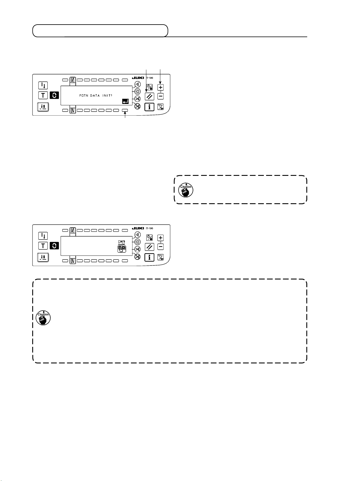
4-15. Initialization of the setting data
Data on the function setting items can be returned to the standard set values.
[Function setting data initialization screen]
3
[PowerswitchOFFnoticationscreen]
1 2
1) Keeping reset switch
and counter value
1
switch (+) 2 held simultaneously pressed, turn
the power ON. Then the screen is changed
over to the function setting data initialization
screen.
2) When you press switch
, the process for
3
totally returning the function setting data to the
standard set values (initialization operation) is
executed.
3) Once the process is completed (approximately
one second later), the buzzer sounds (three
single tones, i.e., blip, blip, blip) and screen is
changed over to the power switch OFF notication screen.
Do not run the power OFF during the ini-
tialization operation. It can damage the
program of the main body.)
4) Turn OFF the power switch to exit from the ini-
tialization.
1. The neutral point compensation value of the pedal sensor is also initialized by carrying out
the initialization operation. It is therefore necessary to carry out the automatic compensation
of the neutral point of the pedal sensor without exceptions before using the sewing machine.
(Refer to "#. 4-14. Automatic compensation of neutral point of the pedal sensor".)
2. The machine head angle adjustment value is also initialized by carrying out the initialization
operation It is therefore necessary to carry out the machine head angle adjustment without
exceptions before using the sewing machine.
(Refer to "@. 1-2. Adjusting the machine head angle".)
3. Sewing data programmed on the operation panel are not initialized by carrying out the initial-
ization operation.
– 47 –
Page 51

5. HOW TO OPERATE THE PRODUCTION SUPPORT FUNCTION
5-1. How to change over the screen under the normal sewing mode
The screens for the pitch time monitor, sewing recorder and production management are displayed by setting
the display on a function-by-function basis after the production support function operation has been enabled
under the information mode.
The following shows how to change over the screen under the normal sewing mode.
<Sewing screen which differs on a model-by-model basis>
T h e s c r e e n i s
changed over wit h
the
(Caution)
Th e scr e e n dis p l a yed
di f f e r s by the se w i n g
machine model.
<Work management screen>
* When the production support func-
tion operation is enabled, the work
management screen is shown with-
out exceptions regardless of the dis-
play setting of other functions.
#
.5-2. Operating the work
management screen
<Pitch time monitor screen No. 1> <Pitch time monitor screen No. 2>
▼
▼
switch.
#
. 5-3. Operating the pitch time monitor screen
<Sewing recorder screen No. 1> <Sewing recorder screen No. 2>
▼
▼
#
. 5-4. Operating the sewing recorder
<Production management screen No. 1> <Production management screen No. 2>
▼
▼
#
. 5-5. Operating the production management function
– 48 –
Page 52

5-2. Operating the work management screen
(1) Work management screen
On the work management screen, work data such as the operator ID, product number and process number,
which are to be embedded in the operation data recorded by each sewing machine are entered and managed. In addition, the recoded operation data can be uploaded. Furthermore, on the work management
screen, operations required for procedures such as count-up of the production volume and stopping of measurement can be carried out. This means that sewing work can be done with this screen displayed.
*
Refer to "#. 5-1. How to change over the screen under the normal sewing mode" for the operating pro-
cedure to be taken until this screen is displayed.
A B C
5
6
1
Switch/display Description
Manual switch A press on this switch increases the number of sewn pieces by one.
1
Product number selection switch This switch is used to display an abbreviated number for the selected prod-
2
Operator ID selection switch This switch is used to display an abbreviated number for the selected op-
3
Optional ID selection switch This switch is used to display an abbreviated number for the selected op-
4
No. of pcs. in lot setting switch In the case of the lot production, the number of pieces in a lot can be
5
Measurement changeover switch This switch is used to stop measurement and recording of the sewing ma-
6
2 3
4
uct number.
When this switch is pressed, the sewing product's product number input
screen is displayed. Refer to
ber input screen"
erator ID.
When this switch is pressed, the operator ID selection popup screen is dis-
played. Refer to
tional ID.
When this switch is pressed, the optional ID selection screen is displayed.
Refer to
counted collectively. The total number of pieces in a lot should be entered.
When this switch is pressed, the No. of pcs. in lot input screen is displayed.
Refer to
chine operation data.
* Measurement is carried out (state):
7
"#-5-2. (2) Sewing product's product num-
.
#
-5-2. (3) Operator ID selection screen"
"
#
-5-2. (4) Optional ID selection screen"
"
#
-5-2. (5) No. of pcs. in lot setting screen”
“
.
.
.
* Measurement is stopped: Sewing machine startup is stopped (state):
Communication selection switch This switch is used to upload measurement data.
7
Display of the current time of day
A
B Display of the latest pitch time The time period between two times of thread trimming is measured and
C
Display of the production volume
When the switch is pressed, the communication selection screen is dis-
played. Refer to
The current time of day is displayed.
displayed.
The production volume under sewing work is displayed.
"#-5-2. (6) Communication selection screen"
.
– 49 –
Page 53

(2) Sewing product's product number selection screen
A B
1
Switch/display Description
Clear switch This switch is used to bring the ID status to the unselected state.
1
No. setting switch This switch is used to select an abbreviated number for the product number.
2
Cancel switch
3
Enter switch
4
Abbreviated number dis-
A
play
Sewing product's prod-
B
uct number display
2 4
This switch is used to cancel the product number selection and to return the screen
to the work management screen.
This switch is used to conrm the selected product number and to return the screen
to the work management screen.
This section displays the two-digit abbreviated number selected with 1.
This section displays the product number which is designated as the one for se-
lected abbreviated number with 16-digit alphanumeric characters at the maximum.
3
(3) Operator ID selection screen
A B
Switch/display Description
Clear switch This switch is used to bring the ID status to the unselected state.
1
No. setting switch This switch is used to select an abbreviated number for the operator ID.
2
Cancel switch
3
Enter switch
4
Abbreviated number dis-
A
play
Operator ID display
B
This switch is used to cancel the operator ID selection and to return the screen to
the work management screen.
This switch is used to conrm the selected operator ID and to return the screen to
the work management screen.
This section displays the two-digit abbreviated number selected with 1.
This section displays the operator ID which is designated as the one for selected
abbreviated number with 8-digit alphanumeric characters at the maximum.
3
2 41
– 50 –
Page 54

(4) Optional ID selection screen
A B
1
Switch/display Description
Clear switch This switch is used to bring the ID status to the unselected state.
1
No. setting switch
2
Cancel switch
3
Enter switch
4
Abbreviated number dis-
A
play
Optional ID display
B
2 4
This switch is used to select an abbreviated number for the optional ID. In the
case an irregular work is selected, the ongoing irregular work screen is displayed.
This switch is used to cancel the optional ID selection and to return the screen to
the work management screen.
This switch is used to conrm the selected optional ID and to return the screen to
the work management screen.
This section displays the two-digit abbreviated number selected with
This section displays the optional ID which is designated as the one for selected
abbreviated number with 8-digit alphanumeric characters at the maximum.
3
1
.
It is possible to load the ID setting data edited by the IA-1 on the operational panel.
In the case you use a USB thumb drive, insert the medium recorded in a given folder into the
sewing machine. In this state, the data are automatically loaded on the operation panel by turn-
ing ON the power to the sewing machine.
(5) No. of pcs. in lot input screen
1
1 3
2
Switch/display Description
No. setting switch This switch is used to enter the number of pieces in a lot.
1
Cancel switch
2
Enter switch
3
This switch is used to cancel the entered number of pieces in a lot and to return the
screen to the work management screen.
This switch is used to conrm the entered number of pieces in a lot and to return
the screen to the work management screen.
– 51 –
Page 55

(6) Communication selection screen
3
1
Switch/display Description
Delivery data selection
1
switch
ISS data communication
2
switch
Cancel switch
3
This switch is used to select the data to be delivered. When it is pressed, the communication data selection screen is displayed.
This switch is used to select the type of ISS communication data. When it is
pressed, the ISS communication type selection screen is displayed.
This switch is used to close the communication selection screen and to return the
screen to the work management screen.
<Delivery data selection screen>
A
1
Switch/display Description
Clear switch This switch is used to bring the ID status to the unselected state.
1
Delivery data setting
2
switch
Cancel switch
3
A
Delivery data display This section displays the two-digit abbreviated number selected with
B
Delivery data display
B
2
This switch is used to select an abbreviated number for the data to be delivered.
This switch is used to cancel the operator ID selection and to return the screen
to the work management screen.
This section displays the delivery data which is designated as the one for selected abbreviated number with 16-digit alphanumeric characters at the maximum.
2
3
1
.
<ISS communication data selection screen>
1 2 4
Switch/display Description
USB selection switch This switch is used to set the destination of the ISS data to the USB thumb drive.
1
PC selection switch
2
Cancel switch
3
Enter switch
4
This switch is used to set the destination of the ISS data to the personal computer.
This switch is used to cancel the selected communication data and to return the
screen to the work management screen.
This switch is used to output the data to the selected destination and to return
the screen to the work management screen.
3
– 52 –
Page 56

5-3. Operating the pitch time monitor screen
The pitch time monitor screen has two different screens, i.e., the screen No. 1 that displays the production
volume and pitch time as a graph, and the screen No. 2 on which the graph-related setting is carried out.
(1) Pitch time monitor screen No. 1
The pitch time monitor screen No. 1 is operated under two different modes, i.e., the production volume graph
mode for displaying the transition of the production volume with time, and the pitch time graph mode for displaying the distribution and variation of pitch time (operation time) per sewing item. The sewing work status can be
checked by changing over the mode between these two on the pitch time monitor screen No. 2.
(1)-1 Production volume graph mode
A graph vertical axis of which represents the production volume and horizontal axis of which represents the
working time of day is displayed. With this graph, the production status over a long period of time can be
checked and the time period where a problem occurs can be found.
In addition, the production volume in the section specied with the cursor
duction volume and average pitch time in the section specied with
monitor screen No. 2. In this way, detailed information on an arbitrary section can be checked.
* Refer to
"Ⅲ. 5-1. How to change over the screen under the normal sewing mode" for the operating pro-
cedure to be taken until this screen is displayed.
can be displayed, and the total pro-
and can be checked on the pitch time
<Pitch time monitor screen No.1 (Production volume graph mode operating switch)>
Production volume count-up switch
Function selector switch
Graph scroll switch
❶
Function shifting switch
❷
❹
❸
Production
volume counter
correction
switch
Display
changeover
switch to display
the pitch time
monitor screen
No.2
❻
❺
<Pitch time monitor screen No.1 (Production volume graph mode displayed information)>
C. Continuous section display
D. Cursor time of day display
A. Production volume graph display
B. Cursor display
– 53 –
F. Latest pitch time display
E. Display of the production
volume in a cursor section
Page 57

Explanation of displayed information and operating switches on the pitch time monitor screen No. 1
(production volume graph mode)
Switch/display Description
A
Production volume graph display A graph vertical axis of which represents the production volume and
horizontal axis of which represents the working time of day is displayed. The ranges of the vertical and horizontal axes can be set on
the pitch time monitor screen No. 2.
B
Cursor display The location of the cursor is displayed.
C
Continuous section display The continuous section set on the graph is displayed.
The total production volume and average pitch time
in a continuous section selected on the pitch time monitor screen
No.2 can be checked.
D
Cursor time of day display The time of day for the section specied with the cursor on the graph
is displayed.
E
Display of the production volume in a
cursor section
F
Latest pitch time display The length of time between two times of thread trimming is mea-
The production volume in the section specied with the cursor on the
graph is displayed.
sured and displayed.
* If the pitch time is equal to or longer than 1800 seconds (30 min-
utes), it will be regard as defective data and ---- will be displayed
instead of the pitch time.
Production volume count-up switch The production volume is counted up with one item added.
1
Function selector switch The cursor or the continuous section selection (beginning and end)
2
is selected.
Function shifting switch Selected function is shifted to the right or left.
3
Graph scroll switch When this switch is pressed shortly, the graph is scroll to the right or
4
left by one section.
When this switch is held pressed for a longer time, the graph is
scrolled to the right or left on a page-by-page basis.
Display changeover switch to display
5
the pitch time monitor screen No. 2
Production volume counter correc-
6
tion switch
The pitch time monitor screen No. 2 is displayed.
The production volume can be corrected by increasing/decreasing
the number shown on the counter in increments of 1.
– 54 –
Page 58

(2) Pitch time graph mode
A graph vertical axis of which represents the production volume and horizontal axis of which represents the
pitch time is displayed. On this graph, variation in the working time is visualized to enable checking whether
there is a problem work.
In addition, the production volume in the section specied with the cursor can be displayed, and the total
production volume and average pitch time in the section specied with and can be checked on the
pitch time monitor screen No. 2. In this way, detailed information on an arbitrary section can be checked.
* Refer to
"#. 5-1. How to change over the screen under the normal sewing mode"
procedure to be taken until this screen is displayed.
<Pitch time monitor screen No. 1 (pitch time graph mode operating switch)>
<Pitch time monitor screen No.1>
for the operating
Production volume count-up switch
Function selector switch
Graph scroll switch
1
Function shifting switch
2
4
3
Production
volume counter
correction switch
6
Display
changeover
switch to display
the pitch time
monitor screen
No.2
<Pitch time monitor screen No.1 (Pitch time graph mode displayed information)>
C. Continuous section display
D. Cursor pitch time display
5
A. Pitch time graph display
B. Cursor display
– 55 –
F. Latest pitch time display
E. Display of the production
volume in a cursor section
Page 59

Explanation of displayed information and operating switches on the pitch time monitor screen No. 1
(pitch time graph mode)
Switch/display Description
A Pitch time graph display A graph vertical axis of which represents the production volume and hori-
zontal axis of which represents the pitch time is displayed.
The ranges of the vertical and horizontal axes can be set on the pitch
time monitor screen No. 2.
B Cursor display The location of the cursor is displayed.
C Continuous section display The continuous section set on the graph is displayed.
The total production volume and average pitch time in a continuous section selected on the pitch time monitor screen No.2 can be checked.
D Cursor pitch time display The pitch time in the section specied by the cursor on the graph is dis-
played.
Display of the production vol-
E
ume in a cursor section
F Latest pitch time display The length of time between two times of thread trimming is measured
Pr o d u c t i o n v o l u m e count-up
1
switch
Function selector switch The cursor or the continuous section selection (beginning and end) is se-
2
Function shifting switch Selected function is shifted to the right or left.
3
Graph scroll switch When this switch is pressed shortly, the graph is scroll to the right or left
4
Display changeover switch to
5
display the pitch time monitor
screen No. 2
Production volume counter cor-
6
rection switch
The production volume in the section specified with the cursor on the
graph is displayed.
and displayed.
* If the pitch time is equal to or longer than 1800 seconds (30 minutes), it
will be regard as defective data and ---- will be displayed instead of the
pitch time.
The production volume is counted up with one item added.
lected.
by one section.
When this switch is held pressed for a longer time, the graph is scrolled
to the right or left on a page-by-page basis.
The pitch time monitor screen No. 2 is displayed.
The production volume can be corrected by increasing/decreasing the
number shown on the counter in increments of 1.
– 56 –
Page 60

(3) Pitch time monitor screen No. 2
<Pitch time monitor screen No. 2>
On the pitch time monitor screen No. 2, the total production volume and the average pitch time in the continuous section selected on the pitch time monitor screen No. 1 are measured and displayed. (Sections
A and B in the gure given below) In addition, the display method employed on the pitch time monitor screen
No. 1 is specied.
B
1
2
3
5 6
4
Switch/display Description
A Total production
volume display
B Av e r a g e pi t c h
time display
G r a p h m o d e
1
c h a n g e o v e r
switch
Graph's horizon-
2
t a l a x i s ra n g e
setting switch
Graph's vertical
3
r a ng e se t t i n g
switch
Pr o d u c t i o n volume
4
count-up switch
A
1
The total production volume in the continuous section selected on the pitch time monitor screen No. 1 is displayed.
(Caution) The production volume is approximately 3200 at the maximum due to the restriction
by the pitch time monitor data capacity.
The average pitch time in the continuous section selected on the pitch time monitor
screen No. 1 is displayed. It should be noted, however, that pitch time data equal to or longer
than 1800 seconds (30 minutes) is judged to be abnormal sewing work and is excluded from
calculation.
The mode of graph displayed on the pitch time monitor screen No. 1 is changed over.
Production volume graph mode :
Vertical axis : Production volume
Horizontal axis : Working time of day
The range of the horizontal axis (time unit in one section) of the graph displayed on the pitch
time monitor screen No. 1 is set.
Under the production volume graph mode :
・
Setting range : 10 m, 15 m, 20 m, 30 m, 1 h, 2 h, 4 h, 8 h, 12 h, 1 d Initial setting : 30 m
* "m" represents minute, "h" represents hour and "d" represents day.
Under the pitch time graph mode:
・
Setting range : 3 s, 5 s, 10 s, 15 s, 20 s, 30 s, 1 m Initial setting : 5 s
* "s" represents second and "m" represents minute.
The range of the vertical axis of the graph displayed on the pitch time monitor screen No. 1 is set.
Setting range: 10, 20, 50, 100, 200, 500, 1000, 2000, 3000, 5000, auto Initial setting : auto
* In the case of "auto," the range is automatically selected to display the production volume on
the vertical axis as large as possible at all times.
The production volume is counted up with one item added.
2
3
7
Pitch time graph mode :
Vertical axis : Production volume
Horizontal axis : Pitch time
Clear switch The pitch time monitor data recorded in the sewing machine memory are cleared.
5
* When this switch is pressed, the clear conrmation popup screen appears. Press switch
to clear the data, or switch to cancel clearing.
M e as u re m en t
6
stop switch
Display changeover
7
switch to display the
pitch t i m e mon i t o r
screen No. 1
Measurement and recording of sewing machine operation data are stopped.
When measurement is being carried out, is displayed.
When measurement is in the stop status, is displayed.
The pitch time monitor screen No. 1 is displayed.
– 57 –
Page 61

5-4. Operating the sewing recorder
The sewing recorder screen consists of two different screens; i.e., the screen No. 1 on which the sewing
speed and the thread trimming timing are continuously measured and displayed as a line graph and the
screen No. 2 on which the sewing machine operation rate/average sewing speed are displayed and setting
of the graph display on the screen No. 1 carried out.
(1) Sewing recorder screen No. 1
On the sewing recorder screen No. 1, the operator's sewing performance is displayed by means of the line
graph showing the sewing speed and the time. Based on the graph, the sewing skill level check and training
of the sewing machine operator can be carried out. Two different data can be indicated on the graph as data
No. 1 and data No. 2. This means that the target operator's data can be shown together with data on a highly
skilled operator's work or the data on his/her work in the past for the purpose of comparison. The comparison
through visualization enables easy analysis of complicated and hard-to-understand sewing machine operation.
<Sewing recorder screen No. 1 (operating switches)>
Active data selector switch
Production volume
count-up switch
Graphs Nos. 1 and 2 display/non-display
changeover switch
1
3
2
Latest work data display switch
Right/left scroll switch
4
<Sewing recorder screen No. 1 (displayed information)>
B. Sewing recorder data No. 1
C. Sewing recorder data No. 2
Production
volume counter
correction switch
7
Display
changeover switch
to display the
6
sewing recorder
screen No.2
5
A. Sewing recorder graph
Point
point in the data No.1.
Point
Point
point in the data No.2.
Point
represents the sewing starting point, thread trimming point or the manual-switch pressing
△
represents the starting and end points of the pitch time of the data No.1.
▲
represents the sewing starting point, thread trimming point or the manual-switch pressing
□
represents the starting and end points of the pitch time of the data No.2.
■
D. Pitch time display of
data in the screen
Upper display : Data No. 1
Lower display : Data No. 2
– 58 –
Page 62

Explanation of displayed information and operating switches on the sewing recorder screen No. 1
Switch/display Description
A Sewing recorder graph
display
Sewing recorder screen No. 1The sewing recorder data No. 1 is shown on the graph in solid lines --------.
B
C
Sewing recorder screen No. 2The sewing recorder data No. 2 is shown on the graph in dotted lines -----.
The graph the vertical axis of which shows the sewing speed and the horizontal
axis of which shows the time is displayed. The ranges of the vertical and hori-
zontal axes can be set on the sewing recorder screen No. 2.
Point △ represents the sewing starting point, thread trimming point or the man-
ual-switch pressing point in the data No.1.
Point ▲ represents the starting and end points of the pitch time of the data
No.1.
Point □ represents the sewing starting point, thread trimming point or the man-
ual-switch pressing point in the data No.2.
Point ■ represents the starting and end points of the pitch time of the data
No.2.
D Pitch time display of data
in the screen
Production volume count-
❶
up switch
Active data selector switch Active data (data to be shifted with switch ❹ or ❺, data to be additionally re-
❷
Graphs Nos. 1 and 2 dis-
❸
play/non-display changeover switch
Right/left scroll switch Data graph that is set to be active is displayed with scrolled to the right or left.
❹
Latest work data display
❺
switch
Display changeover
❻
switch to display the sewing recorder screen No. 2
Production volume count-
❼
er correction switch
The pitch time of the sewing work in which the last thread trimming, on the cur-
rent screen, is performed is displayed.
Upper display : Data No. 1
Lower display : Data No. 2
The production volume is counted up with one item added.
corded when sewing operation is carried out, or data which can be cleared with
Clear switch
Setting only data No. 1
to be active :
Graphs No. 1 and No. 2 are respectively changed over between the display and
non-display.
Display :
The latest work of the data which is set to be active is displayed in a graph from
the beginning of sewing.
The sewing recorder screen No. 2 is displayed.
The production volume can be corrected by increasing/decreasing the number
shown on the counter in increments of 1.
on the screen No. 2) is selected.
Setting only data No. 2 to
be active :
Non-display :
Setting both data to be
active :
– 59 –
Page 63

(2) Sewing recorder screen No. 2
On the sewing recorder screen No. 2, the sewing machine operation rate and the average sewing speed in
the pitch time section displayed on the screen No. 1 is calculated and displayed. (Sections A and B in the gure given below) In addition, the display method employed on the sewing recorder screen No. 1 is specied.
<Sewing recorder screen No.2>
Switch/display
A
Sewing machine
operatio n - r a t e
display
B
Average sewing
speed display
Active data se-
1
lector switch
1
A
2
The rate of the time during which the sewing machine operates in the pitch time shown on the
sewing recorder screen No. 1 is displayed.
Upper display : Data No. 1 Lower display : Data No. 2
The average sewing speed of the sewing machine in the sewing machine operating section within the pitch time shown on the sewing recorder screen No. 1 is displayed.
Upper display : Data No. 1 Lower display : Data No. 2
This switch is used to select the active data (data to be moved by means of switch 4 or 5 on
the screen No. 1, data to be additionally recorded by sewing operation and data that can be
erased by means of the clear switch on the screen No. 2).
B
3
3
4
4
5 6
8
7
Description
Setting only data No. 1
to be active
Production volume
2
count-up switch
Graph's horizontal
3
axis range setting
switch
Graph's verti-
4
cal range setting switch
Clear switch Data which is set to be active is cleared.
5
Measurement
6
stop switch
Data uplo a d /
7
d o w n l o a d
switch
Di s pl a y ch a n g e-
8
o v e r s w i t c h t o
display the sewing
re co r d e r s c r e e n
No. 1
The production volume is counted up with one item added.
The range of the horizontal axis (time unit in one section) of the graph shown on the sewing recorder screen No. 1 is set.
Setting range : 10, 30, 60, 120, 180, 300, 600sec Initial setting : 10 sec
The range of the vertical axis of the graph displayed on the pitch time monitor screen No. 1 is set.
Setting range : auto, 1000, 2000, 3000, 4000, 5000sti/min Initial setting : auto
In the case of “auto,” the range is automatically selected to display the sewing speed on the vertical axis as large as possible at all times.
* It should be noted, however, that the maximum measurable sewing speed can be increased
to 9000 sti/min using
recorder function setting screen.
Measurement and recording of sewing machine operation data are stopped.
When measurement is being carried out, is displayed.
When measurement is in the stop status, is displayed.
The sewing recorder data No. 1 and No. 2 can be uploaded on a medium or downloaded from it,
and can be deleted.
* Refer to the next item
the procedure in detail.
The sewing recorder screen No. 1 is displayed.
"@.2-4.(3) Setting the sewing recorder functions"
"#. 5-4.(3) Uploading/downloading the sewing recorder data"
Setting only data No. 2
to be active
Setting both
data to be active
on the sewing
for
– 60 –
Page 64

(3) Uploading/downloading the sewing recorder data
When the "data upload/download switch" (switch 7 described on the previous page) is pressed, the sewing
recorder communication screen is displayed as shown below.
On this screen, the data can be downloaded from a medium into the sewing machine and can be uploaded
from the sewing machine into a medium.
Data No. 1/No. 2 selector popup screen appears. Select either the
data No. 1 or the data No. 2.
A. Data No. 1/No. 2 selector switch
E. End switch
The popup screen is closed to restore
<Sewing recorder communication screen>
the screen to the previous one.
Production volume
count-up switch
C. File No. selector switch
* File of the selected number stored in a
medium can be deleted.
The le No. selector popup screen appears. Select a le
number of uploaded les on a medium using the Numeric
switches 0 to 9 and + and - switches.
1
D. Upload/download start switch
After having made selections with
switches A, B and C, start uploading or
downloading.
B. Upload/download selector switch
Download from a medium into the sewing machine
Upload from the sewing machine into a medium
The upload/download selector popup screen appears.
Select either uploading from the sewing machine into a
medium or downloading from a medium into the sewing
machine.
– 61 –
Page 65

5-5. Operating the production management function
The production management screen has two different screens, i.e., the screen No. 1 for displaying information on production volume produced by sewing work, and the screen No. 2 for setting the operation for the
screen No. 1.
(1) Production management screen No. 1
On the production management screen No. 1, the target production volume according to the working hours
and the actual production volume are displayed to notify the operator of a delay or progress of sewing work
in real time. With this function, the operator is able to carry out his/her work while checking his/her work pace.
This enhances his/her motivation to achieve his/her goal, thereby leading to a substantial increase in productivity.
<Production management screen No. 1 (Operation switch>
Actual production volume clear switch
Production volume count-up switch
The target production volume setting switch
3
1
2
Measurement stop switch
Display changeover switch to display the production
management screen No.2
<Production management screen No.1 (displayed information)>
D. Delay/progress display
C. Actual production
volume display
B. Target production
volume display
4
Production
volume counter
correction switch
6
5
A. Display of method to calculate
the target production volume
F. Latest pitch time display
H. Daily target production volume display
G. Achievement ratio display
E. Target pitch time display
– 62 –
Page 66

Explanation of displayed information and operating switches on the production management screen
No. 1
Switch/display Description
A Display of method to cal-
culate the target production volume
B
Target production volume display
C
Actual production volume display
D Delay/progress display
E
Target pitch time display The target pitch time for counting up the target production volume according to the
The method to calculate the currently selected target production volume is dis-
played.
: Count-up by the pitch time
to : Count-up by the beginning/nishing times of day of work and
the total production volume
The target production volume as of the current time is displayed.
The actual production volume is displayed.
is displayed when the actual production volume as of the current time is
smaller than the target production volume, or is displayed when the former is
equal to or larger than the latter one.
lapse of time is displayed.
: In the case of count-up by the pitch time, the pitch time that is set on
the production management function setting screen is displayed.
to : In the case of count-up by the beginning/nishing times of day
of work and the total production volume, the pitch time calculated from
the working hours and total production volume are displayed.
F Latest pitch time display Length of time between two times of thread trimming is measured and displayed.
* If the pitch time is equal to or longer than 1800 seconds (30 minutes), it will be
regarded as defective data and ---- will be displayed instead of the pitch time.
G Achievement ratio display The ratio of the actual production volume to the target production volume as of the
current time is displayed.
It allows the operator to know his/her work pace up to the present
H Dail y targ e t pro d u c tion
volume display
Production volume count-
1
up switch
Daily targe t prod u c t i on
2
volume setting switch
Actual production volume
3
clear switch
Measurement stop switch Measurement and recording of sewing machine operation data are stopped.
4
The daily target production volume corresponding to the currently selected target
production volume calculation method is displayed.
The production volume is counted up with one item added.
The daily target production volume is set.
* When the switch is pressed, the numeric input popup screen is displayed. Input
a set value in the popup screen.
The actual production volume is cleared.
On every working day, the existing actual production volume should be cleared
before starting work.
When measurement is being carried out, is displayed.
Display changeover switch
5
to display the production
management screen No. 2
Production volume counter
6
correction switch
When measurement is in the stop status, is displayed.
The production management screen No. 2 is displayed.
The production volume can be corrected by increasing/decreasing the number
shown on the counter in increments of 1.
– 63 –
Page 67

(2) Production management screen No. 2
On the production management screen No. 2, the count-up method for the target production volume and ac-
tual production volume employed on the production management screen No.1 is selected.
Switch/display Description
Display of the target pitch
A
time or the total working
hours
Production volume count-
1
up switch
Target production volume
2
count-up method selector
switch
1
A
2
2
: In the case of count-up by the pitch time, the pitch time set on the produc-
tion management function setting screen is displayed.
to : In the case of count-up by the starting/nishing times of day of
work and the total production volume, the total working hours that are calculated by adding a resting time to the length of time between the starting
time and the nishing time of work is displayed.
The production volume is counted up with one item added.
The count-up method for the target production volume is selected.
: Count-up by the pitch time
The target production volume is counted up by the pitch time A set on the
production management function setting screen.
3
3
4
Actual production volume
3
count-up method selector
switch
Production management
4
s c r e e n No . 1 di s p l a y
switch
to : Count-up by the starting/nishing times of day of work and the
total production volume
The target production volume is counted up by the pitch time that is cal-
culated using the total working hours and the total daily target production
volume. The total working hours are calculated by adding a resting time to
the length of time between the starting time and the nishing time of day
of work.
The actual production volume is displayed and managed on the production management screen No. 1. This switch is used to select whether or not the actual
production volume is managed with associated with the operator ID, product
number or process number.
: The actual production volume is counted up without being associated with
the operator ID, product number and process number which are set on the
work management screen.
: The only actual production volume, which is produced under the condition
where its operator ID, product number and process number totally agree
with those set on the work management screen, is displayed and managed.
The production management screen No. 1 is displayed.
– 64 –
Page 68

$
. INFORMATION
Various data can be set or checked on the information screen.
The information consists of two different levels, i.e., the operator level and the maintenance personnel level.
1. OpERATOR LEvEL
1
1) Turn ON the power.
2) Press switch
Information screen
■
to display the information screen.
1
2
3) When you press switch 2, the sewing management information screen is displayed. When you press
switch 3, the time setting screen is displayed.
3
1-1. Sewing management information
The sewing management information consists of the maintenance management function and working
measurement function.
(1) Maintenance management function
Sewing management function screen
■
1) Press switch
1
to change over the screen to the maintenance management function screen.
1
– 65 –
Page 69

– 66 –
Maintenance function screen
■
The time for needle changing, the time for cleaning and the time for oil changing can be set to continuously
display numeric values or display the notication after the lapse of preset time.
Refer to the Engineer's Manual for details.
2
4
[Explanation of the respective items]
2
3
4
[Explanation of the contents of display]
(Numerator / denominator)
* Number of remaining stitches up to *thousand stitches /
Example) Replacement of needle
Time of replacement of needle ..... Unit : X 1,000 stitches
Time of cleaning ............................ Unit : Hour
Time of replacement of oil ............. Unit : Hour
100 / 1600 k
3
thousand stitches
**
Time of replacement of needle is informed every 1,600 thousand stitches.
Time of replacement of needle is informed after 100 thousand stitches.
When 2, 3 and 4 switches are pressed, the clear checking screen is displayed.
Clear screen
■
1
2
: The screen returns to the maintenance function screen without performing clearing.
1
: The screen returns to the maintenance function screen after executing clearing.
2
Page 70

Warning screen
■
Warning screen is displayed when the warning time is reached.
1
2
: When 1 is pressed, the screen can be cleared. However, the counter itself cannot be cleared. In case
1
of the replacement of needle, the warning screen is displayed at intervals of 10 minutes until clearing
is performed. In case of other warnings, the warning screen is displayed at the time of turning ON the
power until the counter is cleared.
: When 2 is pressed, the screen is cleared and the counter value is cleared as well. From this time,
2
counting starts newly.
[Setting of the warning setting time]
Infomation screen
■
1
1) Press switch 1 for approximately three seconds in the information screen.
Sewing management function screen
■
2
2) Press 2 to display the maintenance function screen.
(For other functions, refer to the Engineer’s Manual.)
– 67 –
Page 71

– 68 –
Maintenance function screen
■
3
4
5
: Input screen of time of replacement of needle (number of stitches : unit : X 1,000 stitches) is displayed.
3
: Input screen of time of cleaning (time : unit : h) is displayed.
4
: Input screen of time of replacement of oil (time : unit : h) is displayed.
5
Various input screen (Time for needle changing, time for cleaning and the time for oil changing)
■
7
Press
In case of stopping the warning function, set the set value to “0”.
It is possible to individually set replacement of needle, cleaning, and replacement of oil respec-
to display the clear checking screen. After inputting the set value, press 8 to determine.
7
tively. In case of stopping all, set “0” to each.
8
Page 72

(2) Working measurement function
Sewing management function screen
■
1
1) Press switch 1 to change over the screen to the working measurement function screen.
Working measurement function screen
■
Working factor, working mean speed, pitch time and machine time can be measured on this screen.
[Explanation of the respective items]
Working factor ..................................Unit : %
Working mean speed ....................... Unit : sti/min
Pitch time .........................................Unit : Second
Machine time ...................................Unit : Second
2) Press 3 to start the working measurement.
3) To stop the measurement, press 3 again.
4) The result of measurement can be cleared with
When “Clear” is not executed, the measurement from the last time can be continued.
2
.
– 69 –
Page 73

– 70 –
1-2. Setting the date and time
Information screen
■
1
1) Press switch 1 to change over the screen to the date and time setting screen.
Date and time setting screen
■
2345678
!0!1!2
!4
9
2) Press switches 2 and 3, 4 and 5, and 6 and 7 to increment/decrement the date.
3) Press switches 8 and 9, !0 and !1, and !2 and !3 to increment/decrement the time.
4) Once you have set the date and time, press switch !4. The screen is changed over to the information
screen.
Information screen
■
5) The set date and time are displayed on the information screen and the clock starts to operate. (When
you have set the date and time to "2009-10-01 10:00:00" and press switch !4, the screen display will be
as shown in the above gure.)
!3
Page 74

2. MAINTENANCE PERSONNEL LEVEL
1
1) Turn the power ON.
2) Keep switch 1 held pressed for approximately three seconds to display the information screen.
Information screen No. 1 (maintenance personnel level)
■
1
No. Setting item Description
Sew i ng com m on da t a
1
screen display switch
Ver. display Refer to the Engineer's Manual for details.
2
Function setting With this setting item, the various functions of the sewing machine can be set
3
Sewing management in-
4
formation
Communication mode Refer to the Engineer's Manual for details.
5
Time setting screen On this screen, the time is set. Refer to
6
Changeover to informa-
7
tion screen No. 2
3 4 5 6 72
This switch is used to set the machine-head type and to set the optional input/
output. Refer to
and the number of stitches and the sewing speed can be changed. Refer to
"#.4-12. Function setting"
With this setting item, the sewing management information screen No. 1 is dis-
played. Refer to
When this key is held pressed for a longer time, the information screen No. 2 is
displayed.
"$.2-1. Sewing common data screen"
.
"$. 1-1. Sewing management information"
"$. 1-2. Setting the date and time"
.
.
.
– 71 –
Page 75

– 72 –
Information screen No. 2 (maintenance personnel level)
■
2 3 41
No. Setting item Description
USB thumb drive format con-
1
rmation screen display switch
Memory switch setting With this setting item, the contents of display related to the work management
2
Network setting screen dis-
3
play switch
In f ormation s c reen No. 1
4
changeover switch
Refer to the Engineer's Manual for details.
function and those called up by operating the switches can be set or changed.
Refer to
This switch is used to set or change the data related to the network function.
Refer to
This switch is used to display the information screen No. 1.
"$. 2-2. Memory switch setting"
"$.2-3. Network setting"
.
.
When you execute formatting of the USB thumb drive, all pieces of data stored on it are erased.
Do not format the USB thumb drive in any case other than initialization of the medium.
2-1. Sewing common data screen
Sewing common data screen No. 1 (maintenance personnel level)
■
7
1 2 3 4 5 6 8
1) Press the respective switches to display the corresponding function screens.
Machine head selection .............With this key, the type of the sewing machine head is set. Refer to
1
"@.1-1. Machine head setting"
Optional input/output setting ......With this key, the optional input/output is set. Refer to
2
tional input/output setting"
Ancillary device 1 setting
3
Ancillary device 2 setting
4
Thread trimmer setting
5
Simplied program editing
6
2) When you press 8, the sewing common data screen No. 2 is displayed. When you press
.
"#.4-13. Op-
.
, the screen
7
is returned to the information screen (maintenance personnel level). When you press , the screen is
returned to the one displayed before the information mode is entered.
Page 76

Sewing common data screen No. 2 (maintenance personnel level)
■
❷
❶ ❸
1) Press the respective switches to display the corresponding function screens.
Alternating vertical movement speed limitation function setting
❶
2) When you press
press ❷, the screen is returned to the information screen (maintenance personnel level). When you
, the screen is changed over to the sewing common data screen No. 1. When you
❸
press
Ancillary device setting screen
■
The ancillary devices 1 and 2 are totally same in terms of their functions and specications. This means the
devices are operated in the same way.
1) Press switch
, the screen is returned to the one displayed before the information mode is entered.
❶
to display the screen on which the type of the ancillary device is selected.
❶
❷
❹
❸ ❺
2) Press switch
3) Press switch
carded and the ancillary device status is brought back to the unselected state.
4) To select AH10MF auto hemmer device as an example, the screen display is changed to the one shown
below.
or ❸ to select the type of the ancillary device.
❷
to conrm the selected device. When you press switch ❹, the selected device is dis-
❺
– 73 –
Page 77

– 74 –
86
!0
7
5) Press switch
played above switch 9) related to the ancillary device "AH10" (MF auto hemmer device). The type of the
parameter function and the parameter set value vary depending on the ancillary device to be selected.
6) To change the parameter set value, press switch
value you want to change. Press switch
7) After the completion of the changing procedure, press switch !1 to return the screen to the previous one.
When you press switch !0, the parameter set value is discarded and is returned to the value before it is
changed.
Thread trimmer setting screen
■
6
or
to check the parameter functions (Nos. 1 to 3) and the parameter set values (dis-
7
9
31
!1
or
6
or 9 to change the parameter set value.
8
5
to display the parameter function and its set
7
2
1) Fine adjustment of the thread trimming action can be carried out.
2) In the case of the thread trimmer of LU-151* series, for example, the following parameters can be adjusted.
1: Instantaneous stop time of thread trimmer
2: Thread trimmer OFF angle 3: Tension release ON angle
3) Select the parameter you want to adjust with switch 1 or 2. Change the set value of the parameter by
means of switch 3 or 4.
4) After the completion of the changing procedure, press switch 6 to return the screen to the previous one.
When you press switch 5, the parameter set value is discarded and the parameter set value status is
returned to the state before it is changed.
4
6
Page 78

Alternating vertical movement speed limitation function setting screen
■
1) The maximum sewing speed needs to be changed depending on the amount of the alternating vertical
movement of the walking foot and presser foot. (Refer to the Engineer's Manual for the SC-922 for details.) The setting screen differs with the machine head type.
Example of setting (for the LU-2200VR type machine head)
73
5
!5
9
!0
or 6.
!7
3
to return the
!0
51
2
2) : Press switch
the dial value of the amount of the alternating vertical movement to be assigned using switch
Specify the speed for the dial value using
3) When you press
changed over between ON and OFF. After the completion of the setting procedure, press
screen to the previous one. When you press 9, the parameter is discarded and the parameter status is
returned to the state before it is changed.
Example of setting (for the machine head other than the LU-2200VR type)
1
or
to select the set value 1 or 2 of the amount of alternating vertical movement. Set
2
or
7
, the status of the alternating vertical movement limitation you have set is
8
64 8
!3!1
or 4.
!2
4) Press switch
to set by means of !3 or !4.
5) When you press
changed over between ON and OFF. After the completion of the setting procedure, press
screen to the previous one. When you press !7, the parameter is discarded and the parameter status is
returned to the state before it is changed.
!1
to specify the speed set value to one from 1 through 4. Specify the speed you want
or
!2
, the status of the alternating vertical movement limitation you have set is
or
!5
!6
!4 !6
!8
– 75 –
to return the
!8
Page 79

– 76 –
2-2. Memory switch setting
Information screen No. 1 (maintenance personnel level)
■
1
1) Turn the power ON.
2) Keep switch 1 held pressed for a longer time until the information screen No. 2 is displayed.
Information screen No. 2 (maintenance personnel level)
■
2
3) Press switch 2 to display the memory switch setting screen.
Page 80

Memory switch setting screen
■
①②③④⑤
⑥
No. Description Initial value
①②
③④
Network ofine setting
Network connection validity/invalidity is selected.
: Network connection is enabled.
: Network connection is prohibited.
Clock correction function
Clock correction validity/invalidity when there is network connection is set up.
: Clock correction is not enabled.
⑦
⑧
⑨
⑩
❸
⑤⑥
⑦⑧
⑨⑩
: The panel clock is corrected in reference to the host PC clock when there is net-
work connection.
Remaining buffer for ISS measurement warning
Warning (E205) is generated when the ISS measurement data capacity stored in the panel
becomes small.
: No warning is generated.
: A warning (E205) is generated when the data capacity to output to the network is
becoming small (if this warning is generated even when the system is connected
to the network, there may be a problem in network connection).
: A warning is generated when the data capacity to output to USB thumb drive is
becoming small. Insert a USB memory in the panel and output data if this warning
is generated.
* It is strongly recommended to select the last one to gather data by means of the
USB thumb drive instead of connecting the operation panel to the network.
Backlight off setting
These keys are used to change over the backlight off setting.
: The backlight is automatically turned off.
:
The backlight status is changed over between on/off by means of the backlight switch.
Backlight off time setting
This item should be set in the case the backlight automatic-off is selected.
10.0
: With this switch, the time to be elapsed until the backlight is automatically turned
off is set. (Unit: Second)
4) After the completion of the aforementioned setting, press switch
the information screen.
– 77 –
. Then, the screen is changed over to
❸
Page 81

– 78 –
2-3. Network setting
Information screen No. 1 (maintenance personnel level)
■
1
1) Turn the power ON.
2) Keep switch 1 held pressed for a longer time until the information screen No. 2 is displayed.
Information screen No. 2 (maintenance personnel level)
■
3
3) Press switch 3 to display the network setting screen.
Network setting screen
■
465
3
4) When you press switch
5) When you press switch
6) When you press switch
7) After the completion of the aforementioned setting, press switch 6. Then, the screen is changed over to
the information screen.
, the MAC address conrmation screen is displayed.
3
, the IP address conrmation screen is displayed.
4
, the serial number conrmation screen is displayed.
5
Page 82

MACaddressconrmationscreen
■
6
A
1) The MAC address is displayed in A. When you press switch 6, the network setting screen is displayed.
IPaddressconrmationscreen
■
51
3
4
2
6
1) When you press switch 1 or 2, the IP address acquisition method is changed over as described below.
DHCP
→
AUTO
Direct input
→
2) In the case the IP address is directly input, the IP address can be set by pressing switch 3 or 4.
3) When you press switch 5, the network setting screen is displayed.
4) When you press switch 6, the input you have made is conrmed. If you have changed the data, the
power OFF screen is displayed.
5) Turn the power off to nish the operation.
Serialnumberconrmationscreen
■
1
A
1) The serial number of the motor is displayed in A. When you press switch 1, the network setting screen
is displayed.
– 79 –
Page 83

. EXTERNAL INTERFACE
Ⅴ
External interface means the section to connect the operation panel and the system which is different from
the operation panel.
For the use and details, refer to the Engineer's Manual.
1) Media slot
Media slot is installed in the face cover located on the left side of operation panel.
2) Ethernet port
An Ethernet connector is provided inside the right side face cover of the operation panel.
3) RS-232C port
RS-232C connector is installed in the rubber cap located on the back side of operation panel.
4) General input port (Production support switch connecting connector)
General input connector, CN105 is installed in the cord outlet cover located on the back side of operation
panel.
. ERROR
Ⅵ
1. ERROR DISPLAY
There are two different kinds of errors, those output from the operation panel and those from
the SC-920 (control box). Both kinds of errors are notied by the error screen and the buzzer.
Three different kinds of screens of the panel display screen appear due to the difference of the procedures.
1) Error screen disappears when the operator removes the cause.
Example) Cover of the slot of media is open. Close the cover.
2) Press the reset switch, and remove the cause of error after erasing the error screen.
3) Remove the cause of error after turning OFF the power.
– 80 –
Page 84

2. ERROR CODE LIST (ERROR DISPLAY IN PANEL)
There are the following error codes in this device. These error codes interlock (or limit function) and inform
the problem so that the problem is not enlarged when any problem is discovered. When you request our
service, please conrm the error codes.
No.
Description of error detected
Media cover open • Cover of the slot of media is open. • Close the cover.
−
Execution of data initializa-
E000
tion (This is not the error.)
E003 Disconnection of synchro-
nizer connector
E004 Synchronizer lower position
sensor failure
E005 Synchronizer upper position
sensor failure
E007 Overload of motor • When the machine head is locked.
E011 Media is not inserted. • Media is not inserted.
E012 Read error • Data of media cannot be read.
E013 Write error • Data of media cannot be written.
E014 Write protect • Media is in the state of writing prohibition.
E015 Format error • Formatting cannot be performed.
E016
External media capacity over
E019 File size over • File is too large.
E032 File interchangeability error • There is no interchangeability of le.
E041 Sewing recorder error • This error number is displayed in the event of a
E044 Date and time error •
E053 Notification of production
support function initialization (This is not an error)
E055 Production management
error
E056 Work management error • This error number is displayed in the event of
E057 Pitch time monitor error • This error number is displayed in the event of
E065 N e t w o r k tr a n s m i s s i o n
failed
E067 ID reading failed • This message is displayed in the case data in
E070 Slip of belt • When the machine head is locked.
E071 Disconnection of motor
output connector
E072 Overload of motor at the
time of thread trimming mo-
tion
E204 USB insertion • This message is displayed in the case the sew-
E205 Warning of ISS buffer re-
maining amount
• When the machine head is changed.
• When the initialization operation is executed
• When position detection signal is not input from
• When the synchronizer has broken.
• Belt is loose.
• Machine head is not proper.
• Motor pulley is not proper.
• When sewing extra-heavy material beyond the
• When the motor does not run.
• Motor or driver is broken.
• Capacity of media is short.
• This error number is displayed after the execu-
• This error number is displayed in the event of
• This message is displayed in the case data
• Belt is loose.
• Disconnection of motor connector • Check the motor output connector for
• Same as E007 • Same as E007
•
If the sewing machine is continuously used with
Cause of occurrence expected Items to be checked
• Check the synchronizer connector (CN33)
the sewing machine head synchronizer.
guarantee of the machine head.
sewing recorder data fault.
This error number is displayed in the event of operation/data fault concerning date or time of day.
tion of initialization of the production support
function or upgrading of the program.
production management work management
data fault.
data fault.
pitch time monitor data fault.
cannot be sent to the personal computer by
way of the network.
the ID le is broken.
ing machine is activated with the USB thumb
drive inserted.
This message is displayed in the case the buffer
storage for storing the ISS data is almost full.
the buffer storage full, the stored pieces of data
will be erased from the earliest one.
for loose connection and disconnection.
• Check whether the synchronizer cord has
broken since the cord is caught in the
machine head.
• Check the belt tension.
• Check the setting of the machine head.
• Check the setting of the motor pulley.
• Check whether the thread has been entangled in the motor pulley.
• Check the motor output connector (4P) for
loose connection and disconnection.
• Check whether there is any holdup when
turning the motor by hand.
• Turn the power OFF and check the media.
• Turn the power OFF and check the media.
• Turn the power OFF and check the media.
• Turn the power OFF and check the media.
• Turn the power OFF and check the media.
• Turn the power OFF and check the media.
• Turn the power OFF and check the media.
• Turn the power OFF and check the media.
• Reset switch
• Reset switch
• Reset switch
• Reset switch
• Reset switch
• Check whether the network has any fault.
• Check whether the data has any fault.
• Check whether there is any holdup when
turning the motor by hand.
• Check the belt tension.
loose connection and disconnection.
• Remove the USB thumb drive.
• Output the data.
– 81 –
Page 85

No.
Description of error detected
E220 Grease-up warning • When the predetermined number of stitches
E221 Grease-up error
E302 Fall detection switch failure
(When the safety switch
works)
E303 Semicircular plate sensor
error
E703 Operation panel is con-
nected to the unexpected
sewing machine. (Error of
sewing machine model)
E704 System version mismatch
E730 Encoder failure
E731 Motor hole sensor failure
E733 Inverse rotation of motor
E808 Solenoid short circuit
E809 Holding motion failure
E810
Solenoid current abnormality
E811 Abnormal voltage • When voltage higher than guaranteed one is
E906 Operation panel transmis-
sion failure
E924 Motor driver failure
E942 Faulty EEP-ROM •
Cause of occurrence expected Items to be checked
has been reached.
• When the predetermined number of stitches
has been reached and the sewing is not possible.
• When fall detection switch is input in the state
that the power is turned ON.
• Semicircular plate sensor signal cannot be
detected.
• The operation panel and the sewing machine
model do not match in the initial communica-
tion.
• The system version is different from the correct
one in the initial communication.
• When the motor signal is not properly inputted. • Check the motor signal connector (CN39)
• This error occurs when the motor is running at
500 sti/min or more in the opposite direction
of that of rotation indication during motor is
running.
• Solenoid power does not become normal voltage.
• Solenoid is not changed over to holding motion.
• Solenoid rare short-circuit. • Solenoid resistance
inputted.
• 200V has been inputted to SC-920 of 100V
specications.
• JA : 220V is applied to 120V box.
• CE : 400V is applied to 230V box.
• When voltage lower than guaranteed one is
inputted.
• 100V has been inputted to SC-920 of 200V
specications.
• JA : 120V is applied to 220V box
• Inner circuit is broken by the applied overvoltage
• Disconnection of operation panel cord
• Operation panel has broken.
• Motor driver has broken.
Data cannot be written on the EEP-ROM.
• Replenish the specied places with grease
and reset.
(For the details, refer to the data of the
machine head.)
• Replenish the specied places with grease
and reset.
(For the details, refer to the data of the
machine head.)
• Check whether the machine head is tilted
without turning OFF the power switch
(sewing machine operation is prohibited
for safety sake).
• Check whether the fall detection switch
cord is caught in the sewing machine or
the like.
• Check whether the fall detection switch
lever is caught in something.
•
Check whether the contact of the tilt detection switch lever with the machine table is
inadequate. (The table has a dent or the
mounting location of the bed strut is too far)
• Check whether the machine head corresponds with the machine type setting.
• Check whether the motor encoder connector is disconnected.
• Connect the operation panel to the correct
model of the sewing machine.
• Re-write the system version to the one
that can be used with the operation panel.
for loose connection and disconnection.
• Check whether the motor signal cord has
broken since the cord is caught in the
machine head.
• Check whether the inserting direction of
the motor encoder connector is wrong.
• Connection of the encoder of main shaft
motor is wrong.
• Connection for the electric power of main
shaft motor is wrong.
• Check whether the machine head cord is
caught in the pulley cover or the like.
• Check whether the solenoid is abnormally
heated. (CTL circuit board asm. Circuit is
broken.
• Check whether the applied power voltage
is higher than the rated voltage + (plus)
10% or more.
• Check whether 100V/200V changeover
connector is improperly set.
In the aforementioned cases, POWER
p.c.b is broken.
• Check whether the voltage is lower than
the rated voltage - (minus) 10% or less.
• Check whether 100V/200V changeover
connector is improperly set.
• Check whether fuse or regenerative resistance is broken.
• Check the operation panel connector
(CN38) for loose connection and disconnection.
• Check whether the operation panel cord
has broken since the cord is caught in the
machine head.
• Turn the power OFF.
– 82 –
 Loading...