

Page 1

IP-420
INPUT INSTRUCTION MANUAL
Page 2

CONTENTS
1. START AND END OF THE BODY INPUT MODE ................................................ 1
1-1. Move to the body input mode ............................................................................................. 1
1-2. Return to the normal sewing mode ................................................................................... 4
2. BASIC OPERATION AND DISPLAY ....................................................................5
2-1. Common button ................................................................................................................... 5
2-2. Body input mode standard screen .................................................................................... 6
2-3. Selection of function ......................................................................................................... 10
2-4. Input the numeric value .................................................................................................... 11
2-5. Specifying the position ..................................................................................................... 12
3. EXAMPLE OF OPERATING PROCEDURE ....................................................... 14
3-1. Pattern input ...................................................................................................................... 14
3-2. Trial sewing ........................................................................................................................ 17
3-3. Modication of the pattern ............................................................................................... 18
3-4. Pattern writing ................................................................................................................... 21
3-5. Pattern reading .................................................................................................................. 22
4. INPUT OF PATTERN ..........................................................................................23
4-1. Ordinary sewing ................................................................................................................ 23
(1) Jump feed (020) ............................................................................................................................... 23
(2) Linear ordinary sewing (023) ...........................................................................................................25
(3) Spline ordinary sewing (024) ...........................................................................................................27
(4) Arc ordinary sewing (025) ................................................................................................................29
(5) Circle ordinary sewing (026) .......................................................................................................... 30
(6) Point sewing (021) ........................................................................................................................... 31
(7) Ordinary sewing (022)......................................................................................................................32
4-2. Zigzag sewing (030 to 033) ............................................................................................... 33
4-3. Offset sewing (034 to 037) ................................................................................................ 35
4-4. Double sewing ................................................................................................................... 37
(1) Double orderly sewing (040 to 043) ................................................................................................. 37
(2) Double reverse sewing (044 to 047) ................................................................................................ 39
(3) Overlapped reverse sewing (050 to 053) ......................................................................................... 40
4-5. Machine control command ............................................................................................... 42
(1) Thread trimming (001) .....................................................................................................................42
(2) The 2nd origin (002) .........................................................................................................................42
(3) Stop (003) ........................................................................................................................................ 43
(4) One revolution of sewing machine (006) .........................................................................................44
(5) Mark 1 and mark 2 (008, 009)..........................................................................................................45
(6) Thread tension controller No. 3 (007) .............................................................................................45
(7) Delay (010) ......................................................................................................................................46
(8) External input (011) .......................................................................................................................... 46
(9) External output (012) .......................................................................................................................47
i
Page 3

(10) Enlargement/reduction reference point (004) ................................................................................48
(11) Inversion point (005) ...................................................................................................................... 49
(12) Thread tension setting (014) .......................................................................................................... 50
(13) Intermediate presser height setting (018) ...................................................................................... 51
(14) Area Classication (016) ................................................................................................................52
(15) Sewing machine stop (019) ...........................................................................................................53
(16) Machine control command deletion (059) ...................................................................................... 54
(17) Sewing speed (092) ....................................................................................................................... 54
4-6. Automatic back-tack (064) ................................................................................................ 55
4-7. Condensation sewing (065) .............................................................................................. 56
4-8. Overlapped sewing (066) .................................................................................................. 57
4-9. Breakpoint (spline and ordinary sewing) ........................................................................ 58
5. MODIFICATION OF THE PATTERN ................................................................... 61
5-1. Point modication ............................................................................................................. 61
(1) Point deletion (070 and 074) ............................................................................................................ 61
(2) Point move (071 and 075)................................................................................................................63
(3) Point adding (076)............................................................................................................................65
5-2. Vertex modication ........................................................................................................... 67
(1) Vertex deletion (072 and 077) ..........................................................................................................67
(2) Vertex move (073 and 078).............................................................................................................. 68
5-3. Element deletion (063) ...................................................................................................... 69
5-4. Jump feed speed change (060) ........................................................................................ 70
5-5. Sewing speed section change (061) ................................................................................ 71
5-6. Sewing pitch change (062) ............................................................................................... 72
5-7. Symmetry ........................................................................................................................... 73
(1) X-axis symmetry (082) ..................................................................................................................... 73
(2) Y-axis symmetry (083) ..................................................................................................................... 73
(3) Point symmetry (084) ....................................................................................................................... 74
(4) Y symmetry pattern inversion orderly sewing (098) ......................................................................... 74
5-8. Shape point modication .................................................................................................. 75
(1) Shape point adding (135).................................................................................................................75
(2) Shape point move (136)...................................................................................................................77
(3) Shape point deletion (137) ............................................................................................................... 78
6. PATTERN OPERATION ...................................................................................... 80
6-1. Pattern copy (086) ............................................................................................................. 80
6-2. Pattern move (085) ............................................................................................................ 81
6-3. Pattern erase (087) ............................................................................................................ 82
6-4. Pattern reading .................................................................................................................. 83
(1) Read the pattern data ...................................................................................................................... 83
(2) Set the enlargement/reduction ratio ................................................................................................. 85
(3) Set the kind of reading data ............................................................................................................. 87
6-5. Pattern writing ................................................................................................................... 89
(1) Write the pattern data ......................................................................................................................89
ii
Page 4

7. FORMATTING MEDIA (090) ............................................................................... 90
8. TRIAL SEWING ..................................................................................................91
8-1. Preparing the trial sewing ................................................................................................. 91
8-2. Performing the trial sewing .............................................................................................. 93
9. SETTING FUNCTION .........................................................................................95
9-1. Comment input .................................................................................................................. 95
9-2. Clamp inversion setting (091) .......................................................................................... 96
9-3. Thread tension reference value setting (113) ................................................................. 96
9-4. Intermediate presser height reference value setting (115) ............................................ 97
10. SELECTING ENDING PROCEDURE (110) ...................................................... 98
11. ALLOCATING FUNCTIONS TO F1 THROUGH F5 BUTTONS (112) .............. 99
12.
DISPLAYING DETAILED INFORMATION ON THE SET VALUE (093) ................ 101
13. DISPLAYING DETAILED INFORMATION ON THE CURRENT NEEDLE
POSITION ....................................................................................................... 103
14. PERFORMING SETTING OF DISPLAY ......................................................... 105
15. ELEMENT FORWARD/BACKWARD (130 and 131) ...................................... 109
16. DIRECT INSTRUCTIONS BY TOUCHING THE SCREEN ............................. 110
16-1. Coordinate direct instructions ..................................................................................... 110
16-2. Needle entry/shape points direct instructions ........................................................... 112
17. PERFORMING SETTING OF THE MEMORY SWITCH DATA ....................... 113
17-1. Setting of the memory switch data is performed ....................................................... 113
17-2. Change over the display language .............................................................................. 114
17-3. Changing the display color of the current point ........................................................ 115
17-4. Setting the zigzag sewing output method ................................................................... 116
18. SELECTING THE FUNCTION CODE TO BE DISPLAYED ............................ 117
19. FUNCTION CODE LIST .................................................................................. 118
20. SETTING RANGE LIST ..................................................................................126
21. BACKUP .........................................................................................................130
22. ERROR CODE LIST .......................................................................................131
23. MESSAGE LIST .............................................................................................. 134
iii
Page 5
1. START AND END OF THE BODY INPUT MODE
1-1. Move to the body input mode
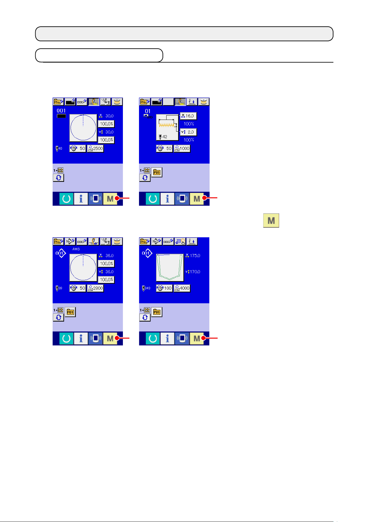
<Data input screen>
①
When the power switch is
②
In order to move from the
A
AMS-E series LK-1900B series
A
Turn ON the power switch.
turned ON, the data input
screen of the normal sewing
mode is displayed after
the welcome screen was
displayed.
Display the mode screen.
normal sewing mode to the
body input mode, press MODE
button A to display
AMS-EN series
A
the mode screen in the state
that the data input screen of
the normal sewing screen is
displayed.
A
AP series
– 1 –
Page 6
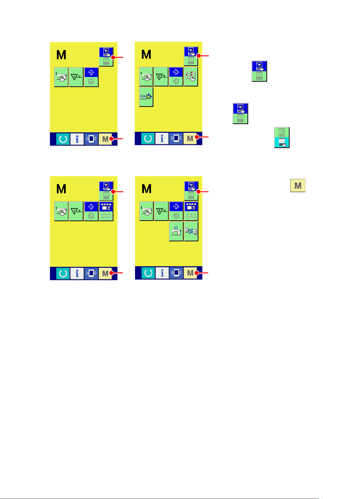
<Mode screen>
B
Select the body input mode.
③
Press MODE SELECTION
B
button B to change over
the display from the normal
sewing mode selection state
to the body input mode
C
AMS-E series
B
C
AMS-EN series AP series
LK-1900B series
C
selection state .
Move to the body input
④
mode.
When MODE button C
B
is pressed in the state that the
body input mode is selected,
the mode moves to the body
input mode, and the backup
data use conrmation screen is
displayed.
* For LK-1900B series, the
standard screen is directly
C
displayed.
– 2 –
Page 7
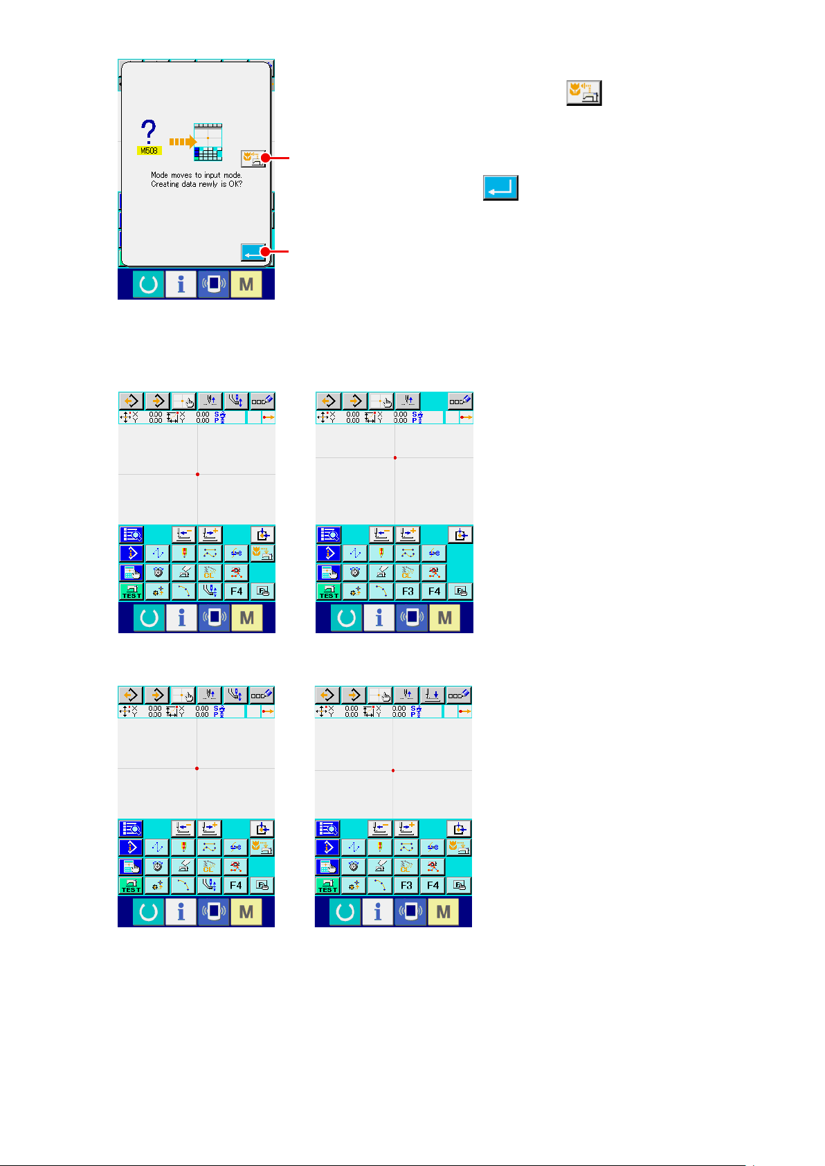
<Standard screen>
Select the sewing data use.
⑤
When SEWING DATA USE button D is pressed, the
body input mode standard screen is displayed in the state that
the backup data is used.
D
When ENTER button E is pressed, new creation can be
performed.
E
AMS-E series LK-1900B series
AMS-EN series AP series
– 3 –
Page 8
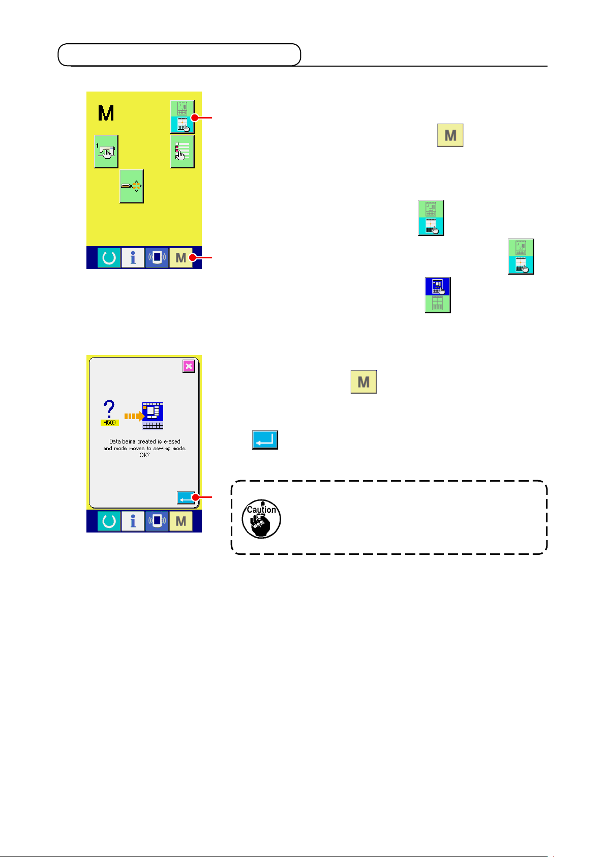
1-2. Return to the normal sewing mode
Display the mode screen.
①
In order to return from the body input mode to the normal
A
sewing mode, press MODE button in the 6tandard
screen to display the mode screen.
Select the normal sewing mode.
②
Press MODE SELECTION button A, and change over
<Mode screen>
B
the display from body input mode selection state to
normal sewing mode selection state .
Change over to the normal sewing mode.
③
When MODE button B is pressed in the state that the
normal sewing mode is selected, the sewing mode move
conrmation screen is displayed. Here, when ENTER button
C is pressed, the data input screen of the normal
sewing mode is displayed.
When the mode moves to the normal sewing
C
mode, the data during creating is erased.
When the data is necessary, perform writing
before moving.
– 4 –
Page 9
2. BASIC OPERATION AND DISPLAY
Explanation is given for the operation and the display which are common to the body input mode.
2-1. Common button
Buttons that perform common operation in the respective screens of the body input mode are as shown
in the list below.
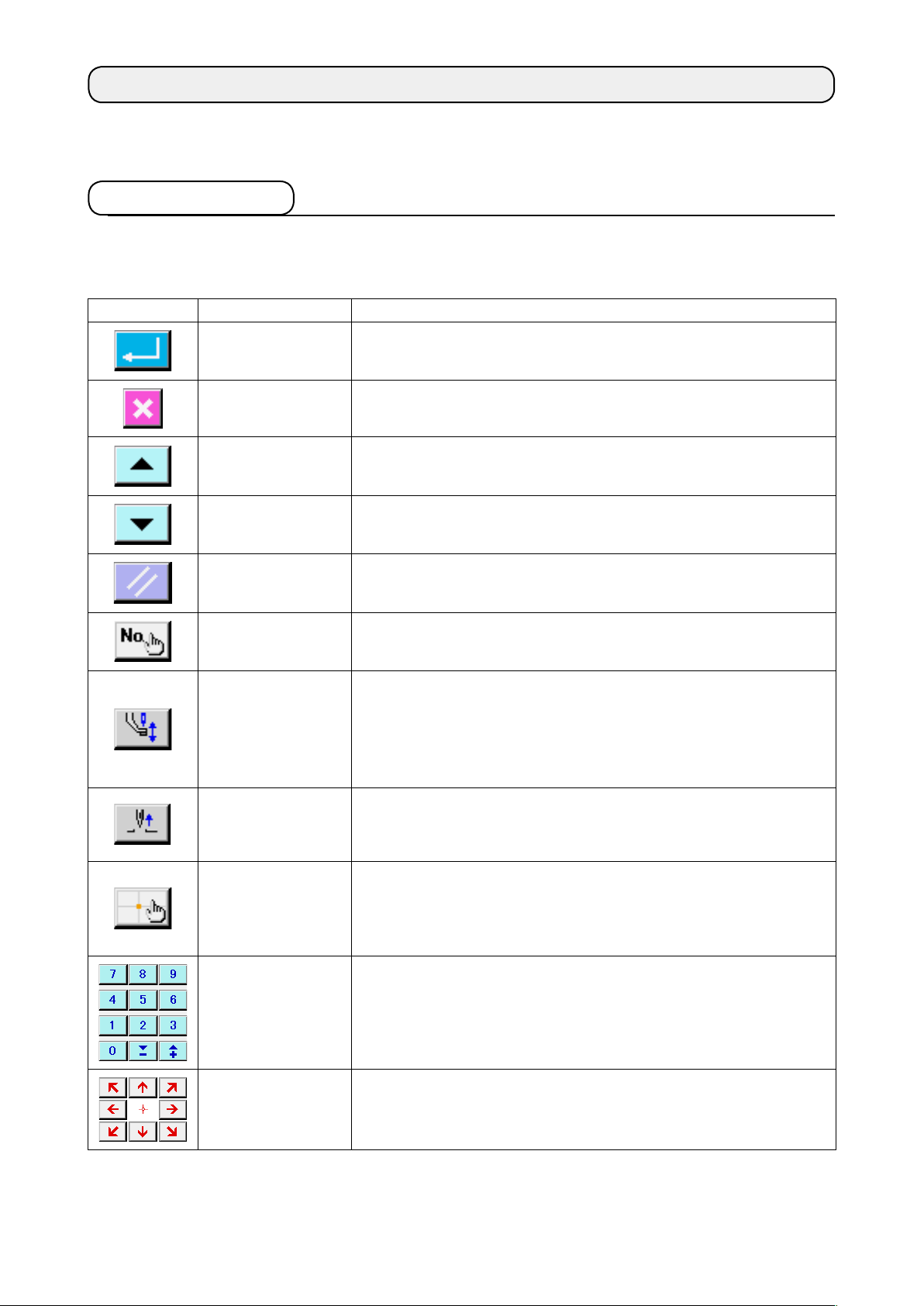
Button Name of button Description
ENTER button Executes the selected function.
In case of the data change screen, the changed data is determined.
CANCEL button Closes pop-up screen.
In case of the data change screen, the data being changed is destroyed.
UP SCROLL button Scrolls the button or display upward.
DOWN SCROLL
button
RESET button Performs the release of error.
NUMERAL INPUT
button
INTERMEDIATE
PRESSER UP/
DOWN button
UP POSITION (UP
DEAD POINT)
RETURN button
COORDINATE
DIRECT
INSTRUCTIONS
button
Scrolls the button or display downward.
Ten-key screen is displayed, and input of numeral can be performed.
Every time this button is pressed, intermediate presser is moved to the
position of up ⇒ medium ⇒ down.
Medium position :
Down position : Input position of intermediate presser command
For LK-1900B series, this screen is not displayed.
*
Returns needle position to UP position (upper dead point).
(Return position depends on the setting of the sewing machine.)
Coordinate direct instructions screen is displayed.
Refer to
→
p.110
"16. DIRECT INSTRUCTIONS BY TOUCHING THE SCREEN"
.
Maximum position of the setting of the sewing machine
TEN key Numeral corresponding to the pressed key is inputted. + and - buttons can
increase or decrease the inputted numeric value.
MOVE key The specied position can be moved to the direction corresponding to the
pressed move key.
– 5 –
Page 10
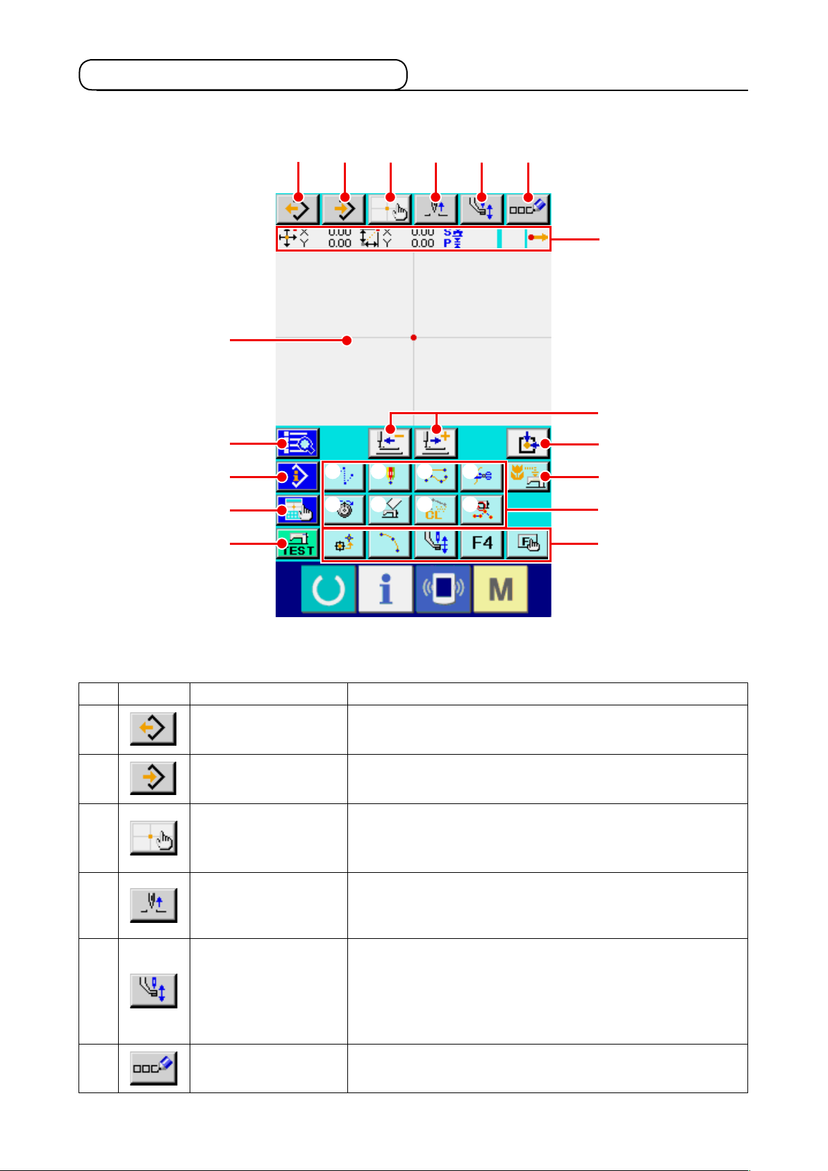
2-2. Body input mode standard screen
The standard screen of the body input mode is as shown below.
P
G
H
I
J
A
B C D E F
① ② ③ ④
⑤ ⑥ ⑦
⑧
Q
K
L
M
N
O
Buttons of the body input mode standard screen are as shown in the list below.
Button Name of button Description
A
B
C
D
E
F
PATTERN READ button Pattern reading screen is displayed.
Refer to
→
PATTERN WRITE button Pattern writing screen is displayed.
Refer to
→
COORDINATE DIRECT
INSTRUCTIONS button
UP POSITION (UP
DEAD POINT) RETURN
button
INTERMEDIATE
PRESSER UP/DOWN
button
COMMENT INPUT
button
Coordinate direct instructions screen is displayed.
Refer to
→
p.112
Returns needle position to UP position (upper dead point).
(Return position depends on the setting of the sewing machine.)
Every time this button is pressed, intermediate presser is moved to
the position of up ⇒ medium ⇒ down.
For LK-1900B series, this screen is not displayed.
*
Comment input screen is displayed.
Refer to
→
"6-4. Pattern reading" p.83
"6-5. Pattern writing" p.89
"16-2. Needle entry/shape points direct instructions"
.
Medium position :
Down position
"9-1. Comment input" p.95
Maximum position of the setting of the sewing machine
:
Input position of intermediate presser command
.
.
.
– 6 –
Page 11
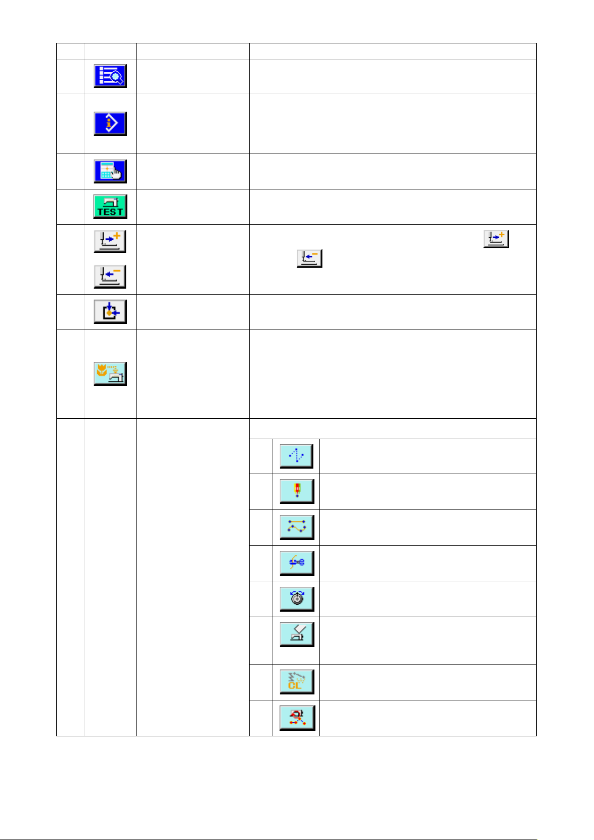
Button Name of button Description
G
H
I
J
K
L
M
CODE LIST button Code list screen is displayed.
Refer to
→
CONTENTS DISPLAY
button
DISPLAY SETTING
button
TRIAL SEWING button Trial sewing screen is displayed.
FEED FORWARD/
BACKWARD button
RETURN TO ORIGIN
button
BACKUP button Performs backup of pattern data to sewing machine.
Contents display screen is displayed, and detailed information on the
present needle position is displayed.
Refer to
→
CURRENT NEEDLE POSITION" p.103
Display setting screen is displayed.
Refer to
→
Refer to
→
Moves the present needle position by one stitch (forward and
backward
when holding pressing a xed number of stitches.
Returns present needle position to the origin.
(Caution : Overwriting is performed on the present pattern data.
When the pattern data is selected from the media in the normal
sewing mode or the users' pattern is being edited, the data will
disappear.)
For LK-1900B series, this screen is not displayed.
*
"2-3. Selection of function" p.10
"13. DISPLAYING DETAILED INFORMATION ON THE
"14. PERFORMING SETTING OF DISPLAY" p.105
"8. TRIAL SEWING" p.91
). The mode becomes the continuous move mode
.
.
.
.
N
FUNCTION button Function allocated to the button can be directly called.
①
②
③
④
⑤
⑥
⑦
⑧
Executes jump feed (
p.23
).
Executes point sewing(
(021)" p.31
Executes normal sewing
(022)" p.32
Executes thread trimming
(001)" p.42
Executes thread tension setting (
tension setting (014)" p.50
Executes machine control command deletion (
(16) Machine control command deletion (059)"
p.54
Executes element deletion (
deletion (063)" p.69
Executes sewing speed section change (
Sewing speed section change (061)" p.71
).
).
).
).
"4-1.(1) Jump feed (020)"
"4-5.(6) Point sewing
"4-1.(7) Ordinary sewing
(
"4-5.(1) Thread trimming
(
"4-5.(12) Thread
).
"5-3. Element
).
"4-5.
"5-5.
).
– 7 –
Page 12
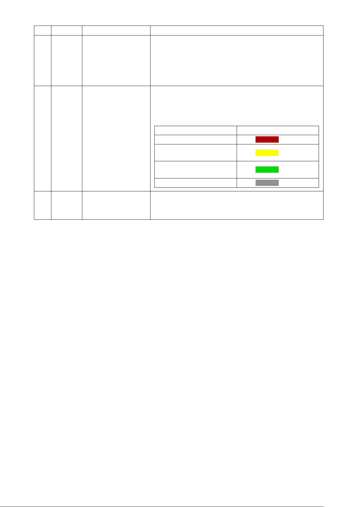
Button Name of button Description
O
P
Q
F button The function you desire can be allocated to each button by means
of function selection and setting (function code 112), and this button
can be used as the function button. When the function is allocated,
pictograph showing the allocated function is displayed.
"11. ALLOCATING FUNCTIONS TO F1 THROUGH F5
.
Kind of point Display color
Current point
sewing start
sewing end
Others
Red
:
Yellow
:
Yellow-green
:
Gray
:
PATTERN DISPLAY
REGION
PRESENT NEEDLE
POSITION
INFORMATION display
Refer to
→
BUTTONS (112)" p.99
Part where pattern is displayed. When pressing down this button,
screen scrolls so that the point becomes the center position of the
display. Screen does not scroll when the outside of sewing area is
pressed.
3 stitches in the direction of
3 stitches in the direction of
Part where information on the present needle position is displayed.
Contents of the display is shown below.
– 8 –
Page 13
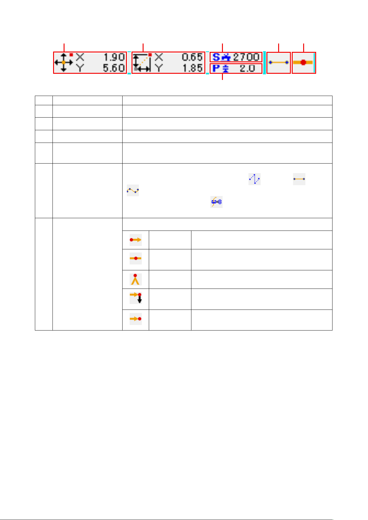
❶
❷
❺ ❻❸
❹
Item Description
Absolute coordinate Absolute coordinate from the origin of the present needle position is displayed.
❶
Relative coordinate Relative coordinate of the present needle position is displayed.
❷
Speed Sewing speed or jump feed speed of the present point is displayed.
❸
Pitch Stitch length of the present element is displayed. (When performing reading after
❹
enlarging/reducing, the value before enlarging/reducing is displayed.)
Kind of element
❺
Kind of needle entry Kind regarding needle entry position is displayed.
❻
The section of present needle position information display can display the comment of pattern by the display setting
"14. PERFORMING SETTING OF DISPLAY" p.105
(
Kind of element of present element is displayed. In case of sewing data, pictograph
in accordance with the kind of element ( jump feed , broken line , spline
, etc. ) is displayed. In case of machine control command, kind of machine
control command (thread trimming , etc. ) is displayed with pictograph.
(For the other pictographs, refer to
Top of pattern Top position (origin) of pattern is displayed.
Midway of
element
Top Top of broken line is displayed.
End of
element
End of
pattern
) as well.
"19. FUNCTION CODE LIST" p.118
Point of midway in element (not the top nor end of
element) is displayed.
End position of element is displayed.
The last position of pattern is displayed.
.)
– 9 –
Page 14
2-3. Selection of function
Procedure of the function selection of the body input mode is given below.
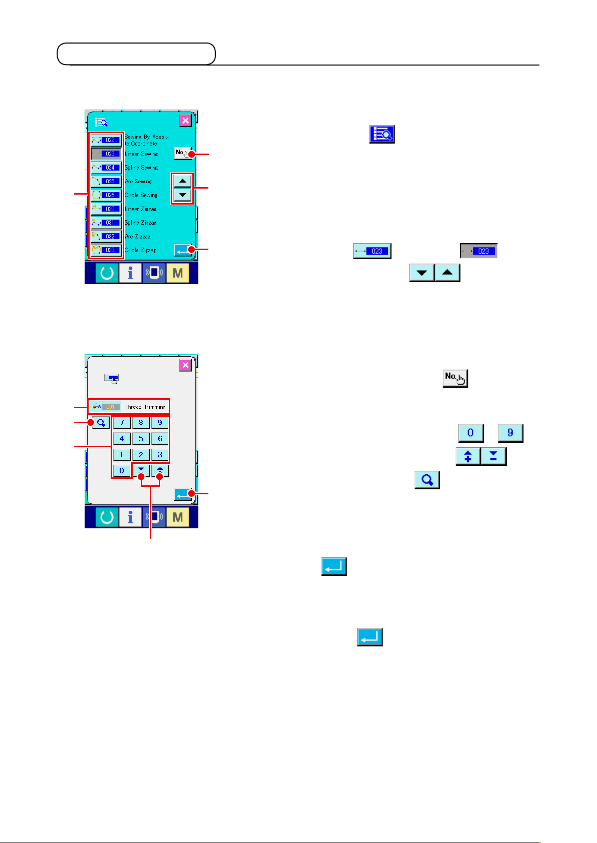
Display the code list screen.
①
When CODE LIST button is pressed in the standard
A
H
G
E
<Code list screen>
C
screen of the body input mode, the code list screen is
displayed.
B
Select the function.
②
Press the calling button of the function you desire to execute
from among the function calling button list A. The selected
D
function calling button is changed to .
When UP/DOWN SCROLL button B is pressed,
the display of function calling button list A is changed over in
order.
Direct input the function code.
③
When FUNCTION CODE INPUT button C is pressed,
the function code input screen is displayed and the function
code can be direct inputted.
Direct input the function code with TEN KEYS to E,
or select the function code with + or - button F.
F
When CONFIRMATION button G is pressed, the
I
information on the function corresponding to the inputted
function code is displayed in the function name display column
.
H
When the function code you desire to execute is inputted and
ENTER button I is pressed, the screen returns to the
function code list screen with inputted function selected.
Execute the function.
④
When ENTER button D is pressed with the function
calling button of the function you desire to execute selected,
setting screen of the function is displayed.
For the respective setting screens, refer to the items of the
respective functions.
– 10 –
Page 15
2-4. Input the numeric value
Common numeric value input procedure at the time of creating the pattern data is given below.
Input the setting item.
①
F
C
D
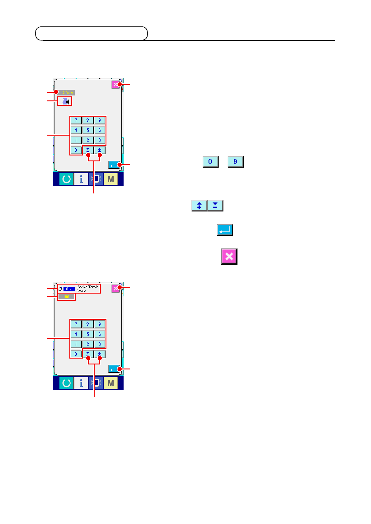
The gure on the right-hand side is the screen which is
displayed when inputting the set value of setting item of the
function.
A
G
C
B
[Example : Change of stitch length]
Kind of setting item to be inputted is displayed at D and the
input value is displayed at C.
When TEN KEY to A is pressed, the numeral of
E
the pressed ten key is inserted to the 1st digit of C, and the
previous input values are moved up by one digit each.
In addition, the input value can be increased or decreased with
+ or - button B. Changeable unit depends on the
kind of setting item.
When ENTER button E is pressed, the input value is
determined and the screen moves.
When CANCEL button F is pressed, the input value is
destroyed and the screen moves.
F
A
B
Input the machine control command parameter.
②
The gure on the left-hand side is the screen which is
displayed when inputting the parameter of machine control
command.
Inputting procedure is the same as that of inputting the set
value of the setting item. At G the function code to perform the
E
input of parameter and the function name are displayed.
– 11 –
Page 16
2-5. Specifying the position
J
K
L
B
A
C
HG
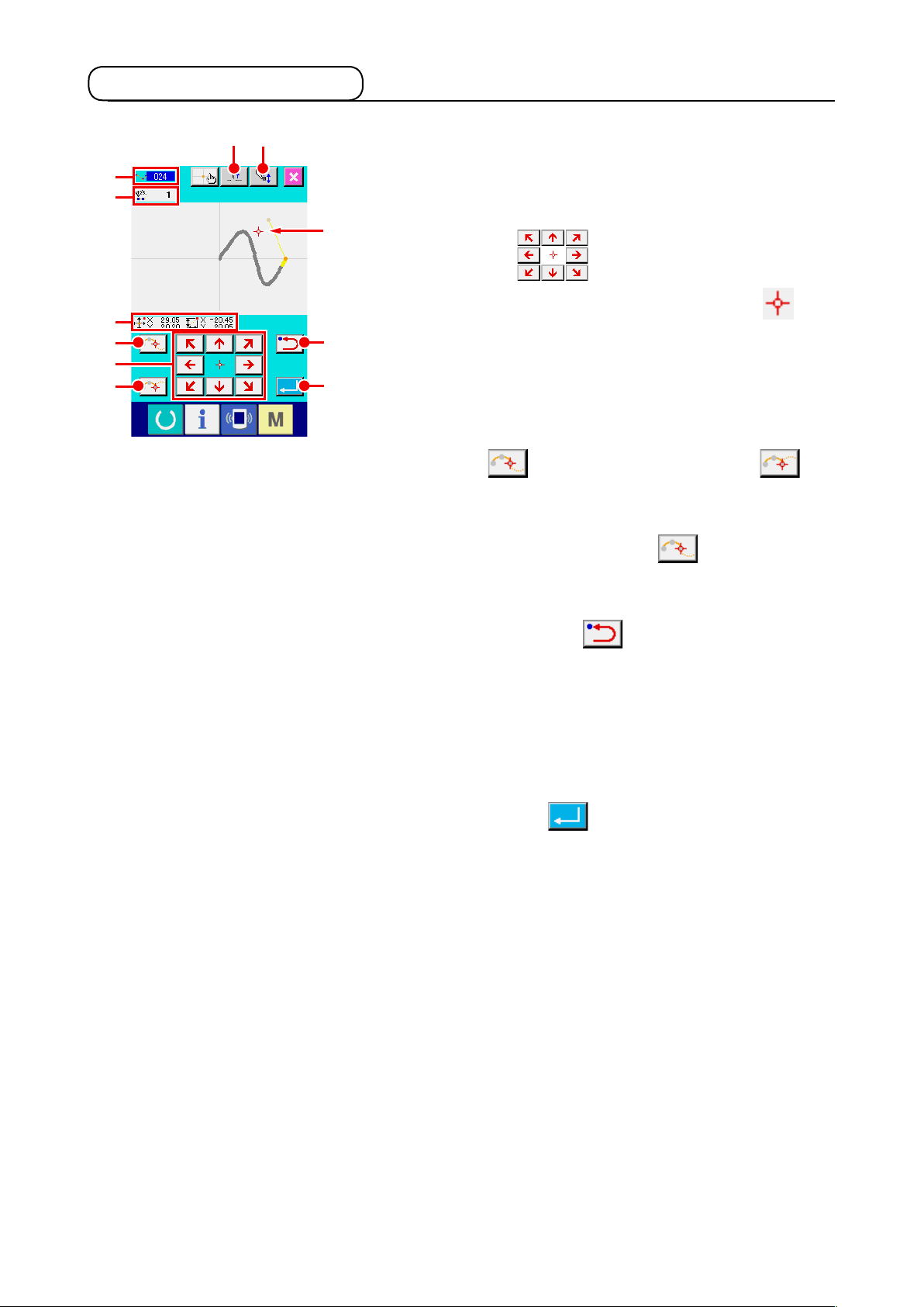
The gure on the right-hand side is the position specifying screen
which is displayed when specifying the position at the setting of
function. The selected function code is displayed at J.
M
Press MOVE key A.
①
The presser and the present needle position display
move in the pressed direction, and the coordinate value
D
M
display L is updated. While MOVE key is held pressed,
E
the presser moves in the pressed direction, and when it is
detached, the move of presser stops.
When the presser moves to the target position and PASSING
POINT button B or DECIDING POINT button
is pressed, the position is inputted as the shape point
C
or the needle entry point. At K the number of input points
is displayed. PASSING POINT button B may not be
displayed according to the selected function.
Press BACKWARD button D after moving with MOVE
②
key.
The position returns to the preceeding determined position.
When it is pressed immediately after the determination of input
position, one point of the determined input points is cancelled
and the position returns to the input point before one point.
Press ENTER button E.
③
The outer presser automatically returns to the position where
input was started, traces the element which was operated and
created at the input point inputted until then, moves to the last
of the element, and the data is inserted.
(With/without trace can be selected. For the details, refer to
"10. SELECTING ENDING PROCEDURE (110)" p.98
.)
– 12 –
Page 17
F
Press CANCEL button I.
④
I
The data during inputting is destroyed, and the screen returns
to the standard screen.
By pressing ENTER button at inputting of the last point,
pressing down of the deciding point button can be omitted.
Press COORDINATE DIRECT INSTRUCTIONS button
⑤
.
F
The coordinate direct instructions screen (
direct instructions" p.110
) is displayed, and the coordinate
"16-1. Coordinate
can be direct specied.
At N warning pictograph is displayed when setting
possible range is exceeded or the like.
N
– 13 –
Page 18
3. EXAMPLE OF OPERATING PROCEDURE
A series of operating procedure up to trial sewing is given below. For the details, refer to the respective
items.
3-1. Pattern input
Create the pattern below using the input function.
Thread
trimming
A
Linear line (pitch 3 mm)
❶
❷
❹
❺ ❸
Origin
Jump feed
Input of jump feed
①
Press JUMP FEED button A in the standard screen to
[Input point]
X(mm) Y(mm)
❶
❷
❸
❹
❺
−5.0 5.0
5.0 5.0
5.0 1.0
0.0 3.0
−5.0 1.0
display the jump feed setting screen.
<Standard screen>
Press ENTER button B in the jump feed setting screen
to display the jump feed position specifying screen.
B
– 14 –
Page 19
❶
C
Move the needle position up to ❶ using MOVE key
in the jump feed position specifying screen, press
C
DECIDING POINT button D, and press ENTER button
E.
D
F
E
At this time, the presser moves. So, be careful.
Input of the linear ordinary sewing
②
Press CODE LIST button F in the standard screen to
display the code list screen.
Select the linear ordinary sewing (function code 023) in the
function code list screen, and press ENTER button .
G
Press STITCH LENGTH SETTING button G in the
linear ordinary sewing setting screen to display the stitch
length setting screen.
Press TEN key in the order of “3” and “0”, and press ENTER
H
button in the stitch length setting screen.
Return to the linear ordinary sewing setting screen, confirm
that the display of stitch length setting button is “3.0 mm”, and
press ENTER button H.
– 15 –
Page 20
❶
❺
I
J
Press MOVE key I in the linear ordinary sewing
❷
❹
❸
position specifying screen, move the needle position from ❶
to ❷, and press DECIDING POINT button J.
Repeat this operation to input up to the position of ❺, and
press ENTER button K.
K
At this time, the presser moves. So, be careful.
Input of thread trimming
③
Press THREAD TRIM button L in the standard screen
to display the thread trimming conrmation screen.
L
Press ENTER button M and input thread trimming to the
position of ❺.
M
The standard screen is displayed, and is displayed at N.
N
With the aforementioned operation, a pattern as shown in the
gure on the left-hand side is created.
– 16 –
Page 21
3-2. Trial sewing
The shape or the like of the pattern created by using the input function or readout data is conrmed with
the trial sewing.
Screen and setting possible item of trial sewing change in accordance with machine models.
Description below is the example regarding AMS-210EN.
Before performing the trial sewing, it is necessary to register the setting of the
height of intermediate presser and that of the thread tension.
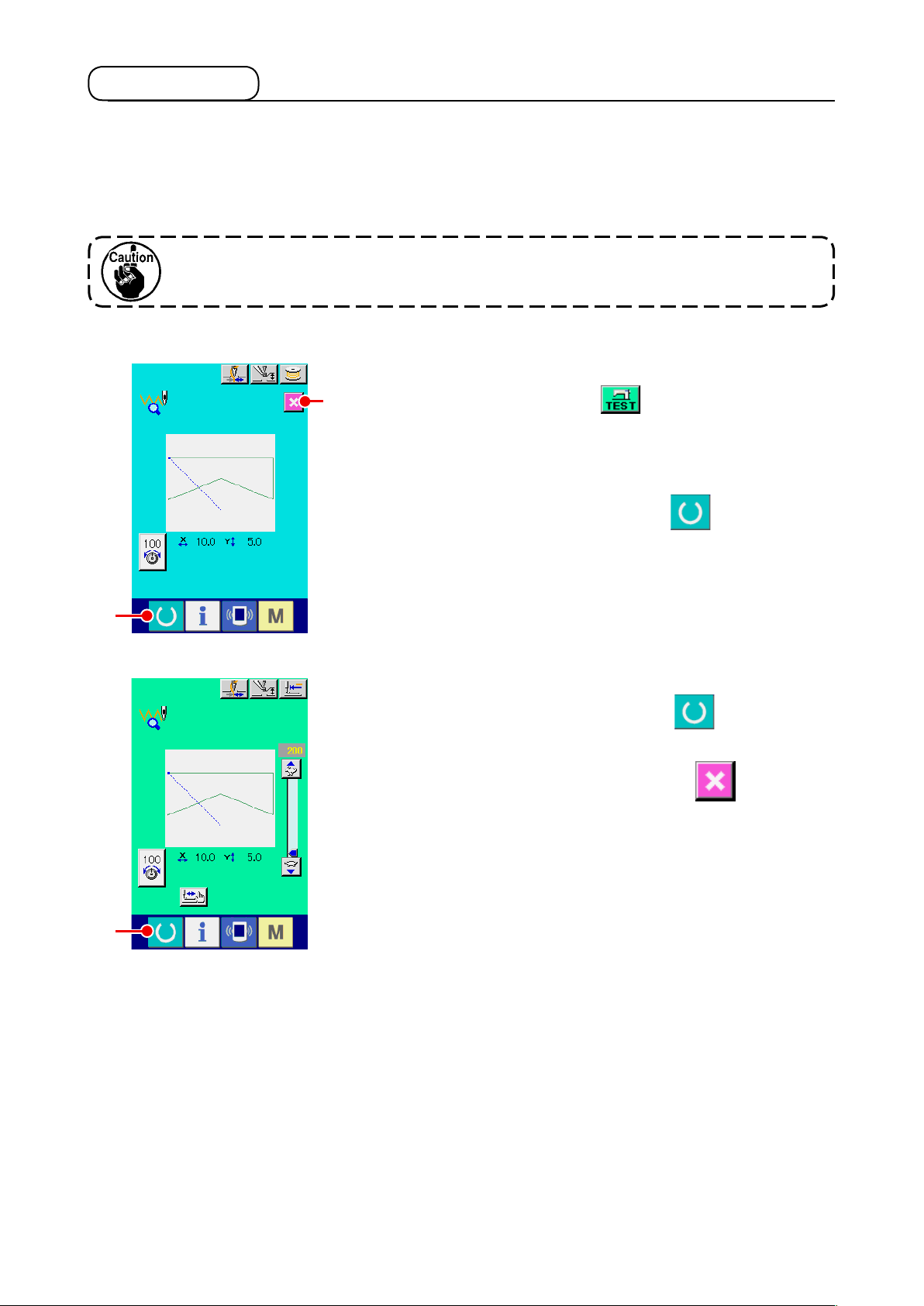
Display the trial sewing preparation screen.
①
Press TRIAL SEWING button in the standard screen to
B
display the trial sewing preparation screen.
Display the trial sewing screen.
②
When SEWING PREPARATION button A is pressed,
A
C
the trial sewing screen is displayed. Perform the normal
sewing machine operation in this screen and the trial sewing
of pattern data can be performed.
Return to creation of pattern.
③
When SEWING PREPARATION button C is pressed in
the trial sewing screen, the screen returns to the trial sewing
preparation screen. When CANCEL button B is pressed
here, the screen returns to the body input mode standard
screen.
– 17 –
Page 22
3-3. Modication of the pattern
Modify the pattern data which has been created in
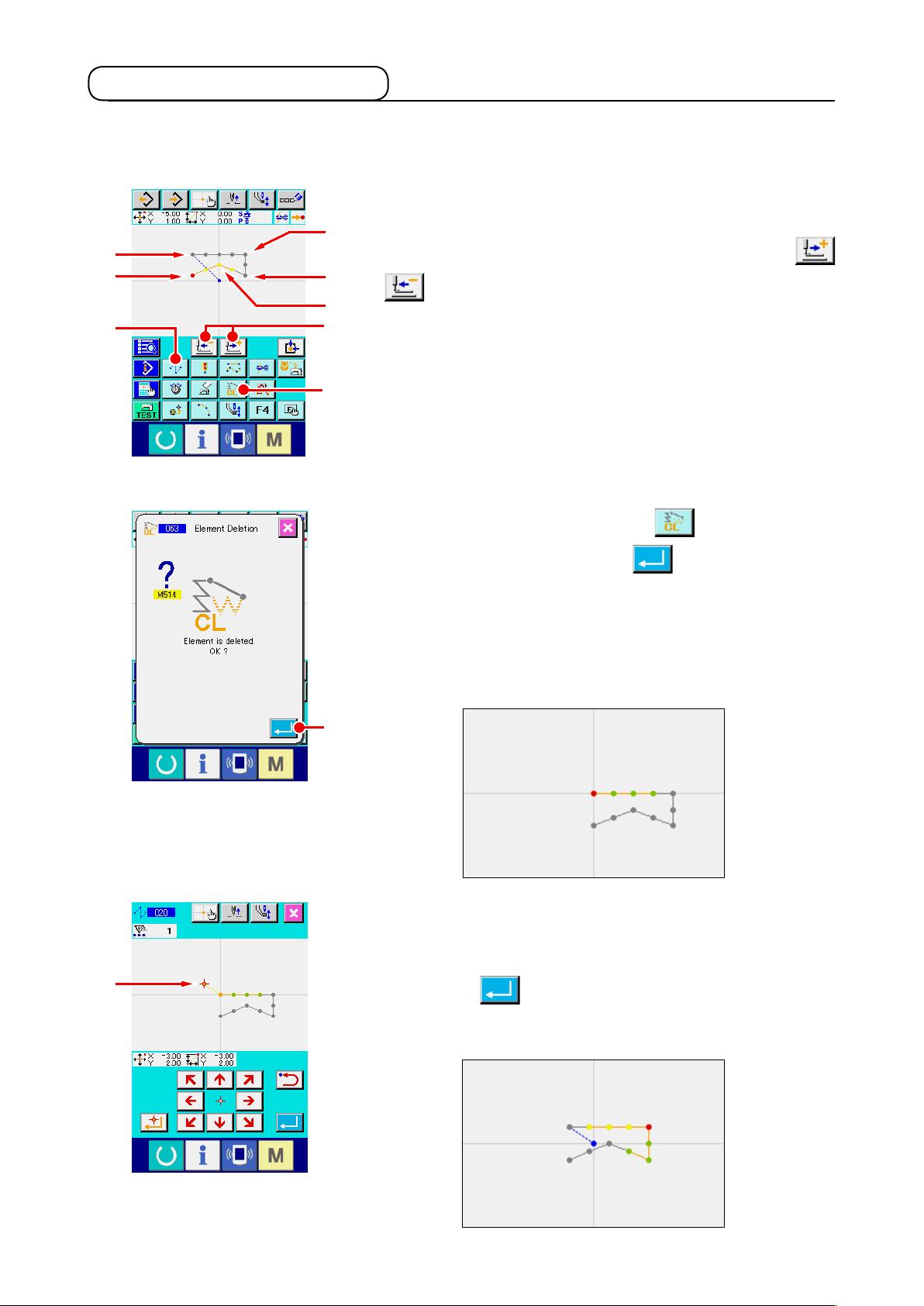
Deletion of element
①
Move the needle position on the way of the jump feed section
❷
❶
❺
E
❸
❹
A
B
<Standard screen>
up to ❶ using FEED FORWARD/BACKWARD buttons
A.
Press ELEMENT DELETION button B in the standard
screen, and press ENTER button C in the conrmation
"3-1. Pattern input" p.14
.
D
screen.
Jump feed up to ❶ is deleted, and the needle position returns
to the origin.
At this time, linear sewing from ❶ through ❺ is in the state of
starting from the origin.
C
Insertion of jump feed
②
Select the jump feed function E on the standard screen. Move
the needle position to D on the position specifying screen.
Press button C.
It can be visually checked that a jump is inserted and the
relative movement of the needle position is caused.
– 18 –
Page 23
Deletion of point
③
Move the needle position up to the position of E in the
E
standard screen using FEED FORWARD/BACKWARD buttons
A.
Select ABSOLUTE POINT DELETION (function code 074)
from the function code list to display the range
specifying screen.
F
In case of deleting plural needle entry points, press FEED
G
FORWARD button F to move the needle position, and
specify the section of the points to be deleted. Here, specify
point E only, and press ENTER button G.
It is conrmed that point E has been deleted as shown in the
gure below.
H
J
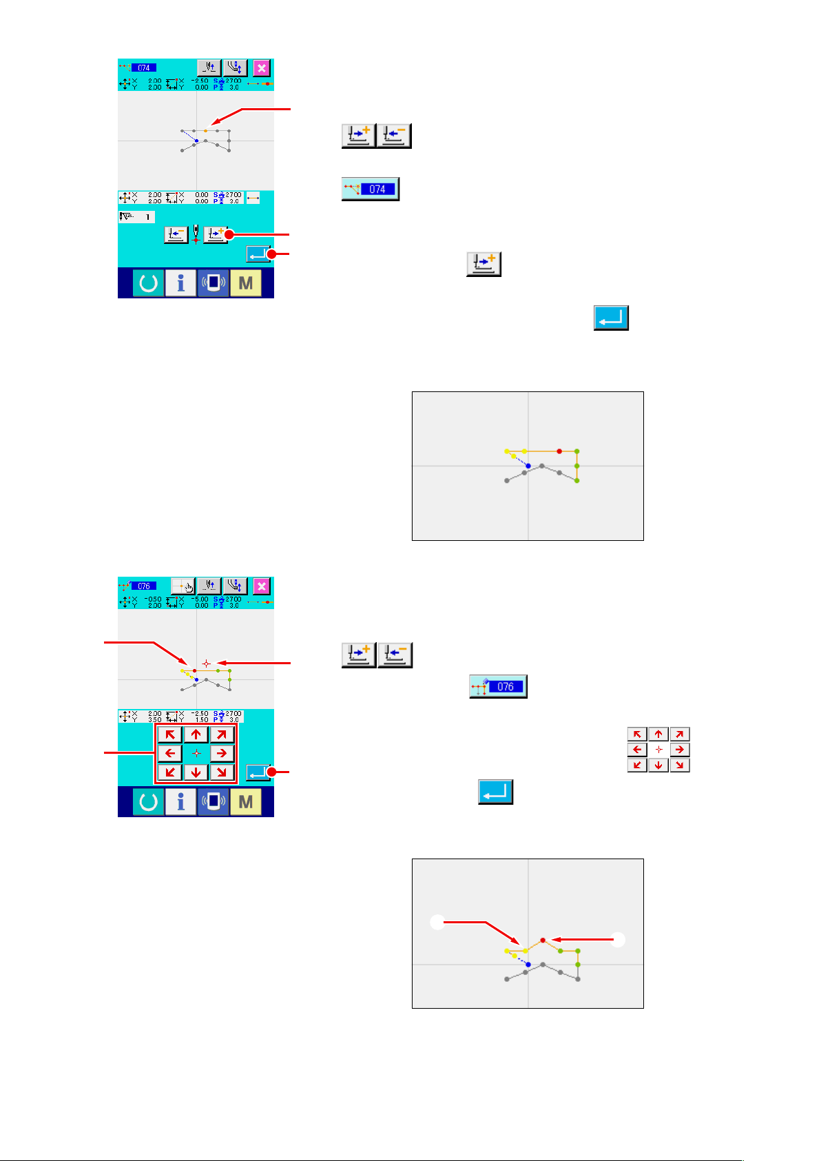
Addition of point
④
Move the needle position up to the position of H in the
standard screen using FEED FORWARD/BACKWARD buttons
I
A, and select ABSOLUTE POINT ADDITION
(function code 076) .
Move the needle position up to the adding point I in the
position specifying screen using MOVE key J, and
K
press ENTER button K.
The needle entry point is added as shown in the gure below.
H
I
– 19 –
Page 24
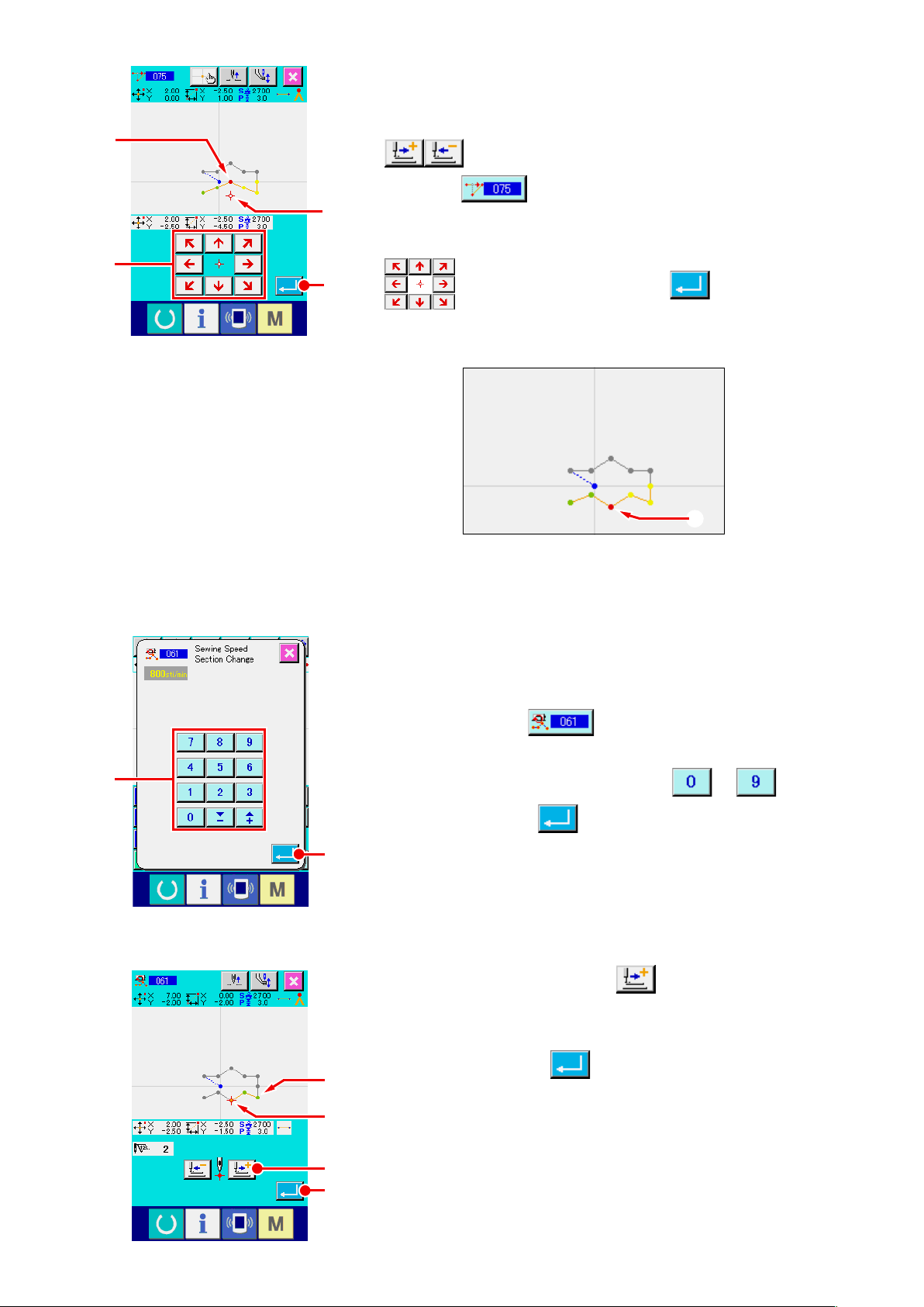
L
N
Move of point
⑤
Move the needle position up to the position of L in the
standard screen using FEE FORWARD/BACKWARD buttons
A, and select ABSOLUTE POINT MOVE (function
code 075) .
M
Move the needle position up to the position M of the moving
point in the position specifying screen using MOVE key
O
N, and press ENTER button O.
The needle entry point moves as shown in the gure below.
M
P
Change of speed
⑥
After moving the needle position up to the position of ❸ in the
standard screen, select SEWING SPEED SECTION CHANGE
(function code 061) .
Input the changing speed (example here is 800 rpm) in the
set value input screen using TEN keys to P, and
press ENTER button Q.
Q
Press FEED FORWARD button R in the position
specifying screen, and move the needle position up to section
you desire to change the speed.
M
When ENTER button S is pressed, the speed of the
❸
specified section is changed, and the screen returns to the
M
standard screen.
R
S
– 20 –
Page 25
3-4. Pattern writing
The created pattern is written to the media.
Use the media which has been formatted with IP-420.
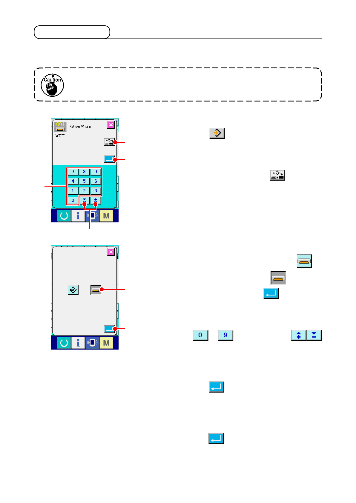
Display the pattern writing screen.
①
Press WRITE button in the standard screen to display
A
the pattern writing screen.
C
D
B
Select the object media selection screen.
②
Press OBJECT MEDIA SELECTION button A to display
the object media selection screen.
Select the object media.
③
Select the media of writing object. Here select MEDIA E.
The selected media is changed in color . When the
E
media is selected, press ENTER button F to return to
the pattern writing screen.
Select pattern No.
④
F
Press TEN key to C, or + or - button
in the pattern writing screen to specify the pattern No. which
D
is open next.
Write pattern.
⑤
When ENTER button B is pressed, writing to the media
is started. When writing is ended, the standard screen is
displayed.
When a pattern exists in the pattern No. of the specied writing
destination, the overwriting conrmation screen is displayed.
When ENTER button is pressed there, writing is started.
– 21 –
Page 26
3-5. Pattern reading
Pattern data written to the media is read in.
Use the media which has been formatted with IP-420.
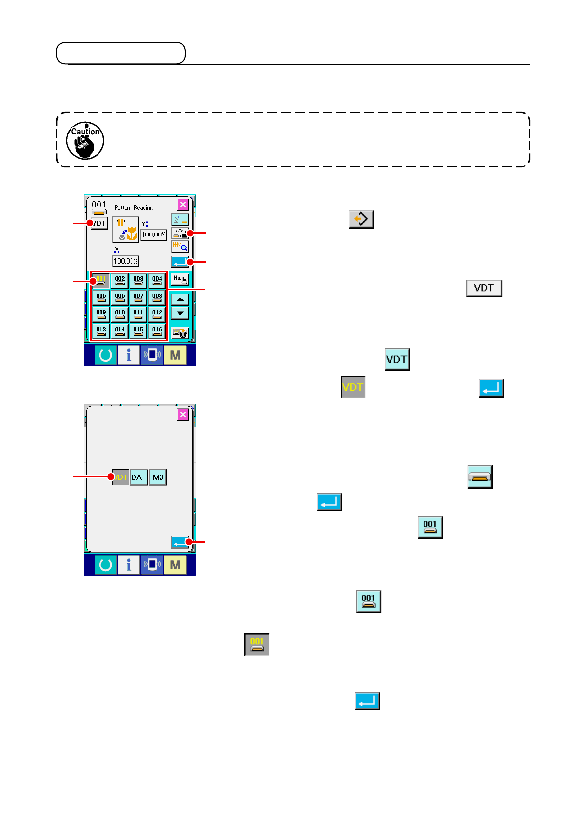
Display the pattern reading screen.
①
C
D
F
Press READ button to display the pattern reading
A
B
E
screen.
Display the pattern kind selection screen.
②
Press PATTERN KIND SELECTION button C to
display the pattern kind selection screen.
Select the pattern kind.
③
Here select VECTOR DATA F. The selected button
is changed in color .When ENTER button G is
pressed, the screen returns to the pattern reading screen.
Select the object media.
④
Press OBJECT MEDIA SELECTION button A to display the
object media selection screen. Select MEDIA , press
ENTER button , and the screen returns to the pattern
reading screen. PATTERN button D of the pattern
G
existing in the part of E is displayed.
Select the pattern.
⑤
Press PATTERN button D of the pattern No. you desire
to read in. The selected pattern button is changed in color
.
Read the pattern.
⑥
When ENTER button B is pressed, reading of the
pattern is started. When the reading of pattern is ended, the
standard screen is displayed.
– 22 –
Page 27
4. INPUT OF PATTERN
4-1. Ordinary sewing
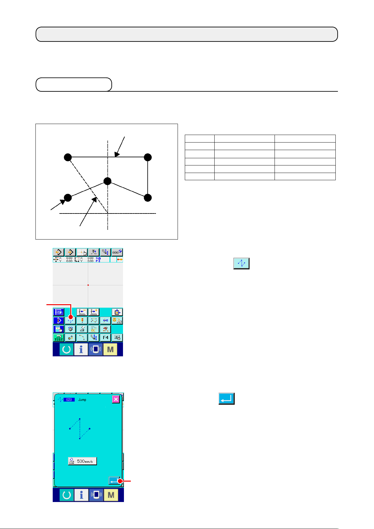
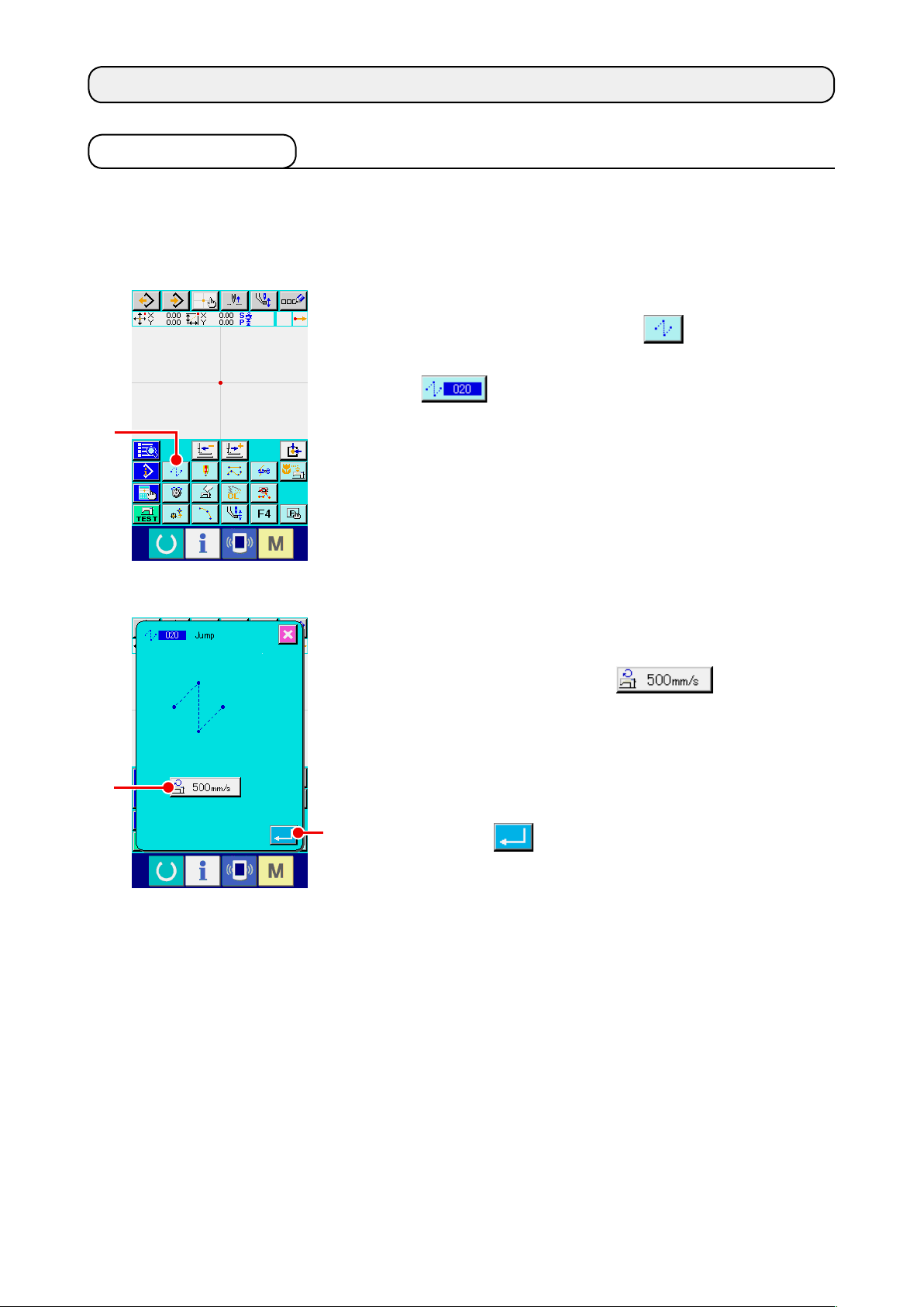
(1) Jump feed (020)
This is used when moving the presser to the specied position without driving the sewing machine.
Display the jump feed setting screen.
①
When pressing JUMP FEED button A in the standard
screen or selecting and executing JUMP FEED (function code
020) in the code list screen, the jump feed setting
A
B
screen is displayed.
Set the jump feed.
②
Present jump feed speed set value is displayed at JUMP
FEED SPEED SETTING button B in the jump
feed setting screen.
When changing the jump feed speed, press the jump feed
speed setting button, and the jump feed speed input screen is
displayed.
After setting or when it is not necessary to change, press
C
ENTER button C, and the coordinate input screen is
displayed.
– 23 –
Page 28
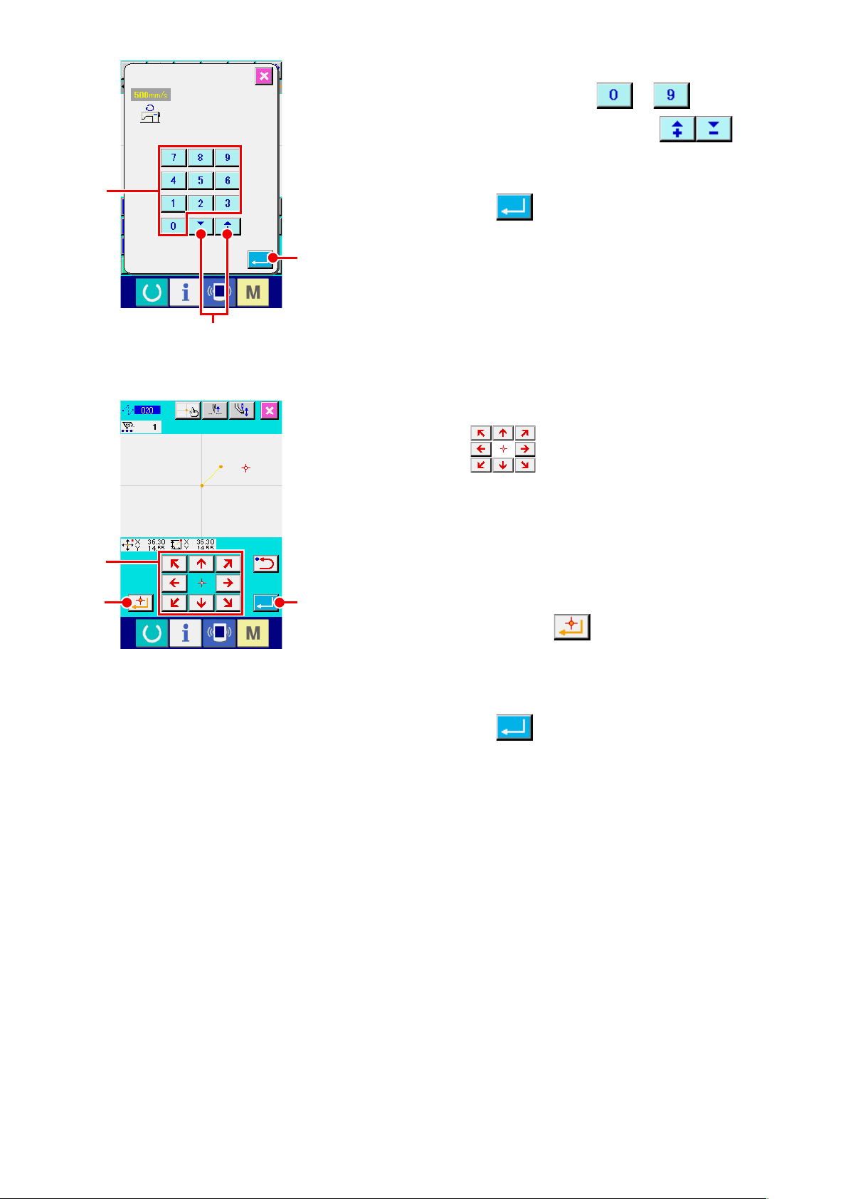
D
E
Set the jump feed speed.
③
Direct input the value with TEN keys to D or
increase/decrease the value with + or - button E
in the jump feed speed input screen, and set the jump feed
speed.
When ENTER button F is pressed, the input value
becomes effective, and the screen returns to the jump feed
F
setting screen.
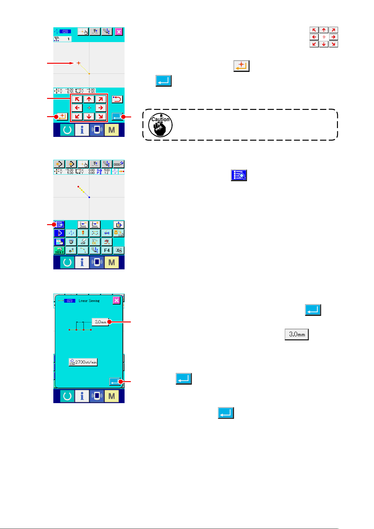
Move the needle position.
④
Press MOVE key G in the coordinate input screen,
G
H
and the needle position moves in the specied direction. While
MOVE key is held pressed, the needle position continuously
moves.
Input the coordinate.
⑤
When the needle position has moved to the specied position
I
and DECIDING POINT button H is pressed, the position
is inputted as the shape point (passing point).
End the setting of jump feed.
⑥
When ENTER button I is pressed, the set data is
inputted, and the screen returns to the standard screen.
It is possible to input by repeating the operation of steps ④
and ⑤ as well.
– 24 –
Page 29
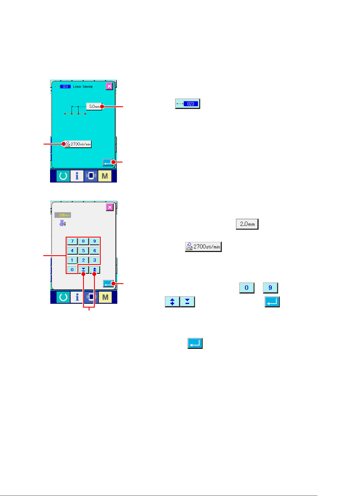
(2) Linear ordinary sewing (023)
When one point is specied, the straight line connecting the point and the needle position is inputted as
the specied stitch length.
Display the linear ordinary sewing setting screen.
①
Select and execute LINEAR ORDINARY SEWING (function
B
D
A
code 023) in the code list screen, and the linear
ordinary sewing setting screen is displayed.
C
Set the linear ordinary sewing.
②
The set value of the present stitch length is displayed at
STITCH LENGTH INPUT button A and the set value
of the present sewing speed is displayed at SEWING SPEED
INPUT button B in the linear ordinary sewing
setting screen.
When the button of the item you desire to change the setting
the input screen of the set value is displayed. Set the value
F
in the input screen with TEN keys to D, or + or -
E
button E, press ENTER button F and the
input value is determined. Then the screen returns to the linear
ordinary sewing setting screen.
After setting, or when it is not necessary to change, press
ENTER button C in the linear ordinary sewing setting
screen, and the coordinate input screen is displayed.
– 25 –
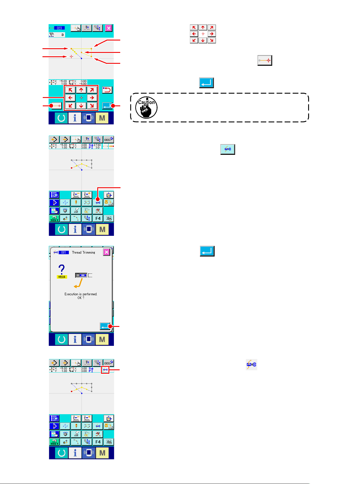
Page 30
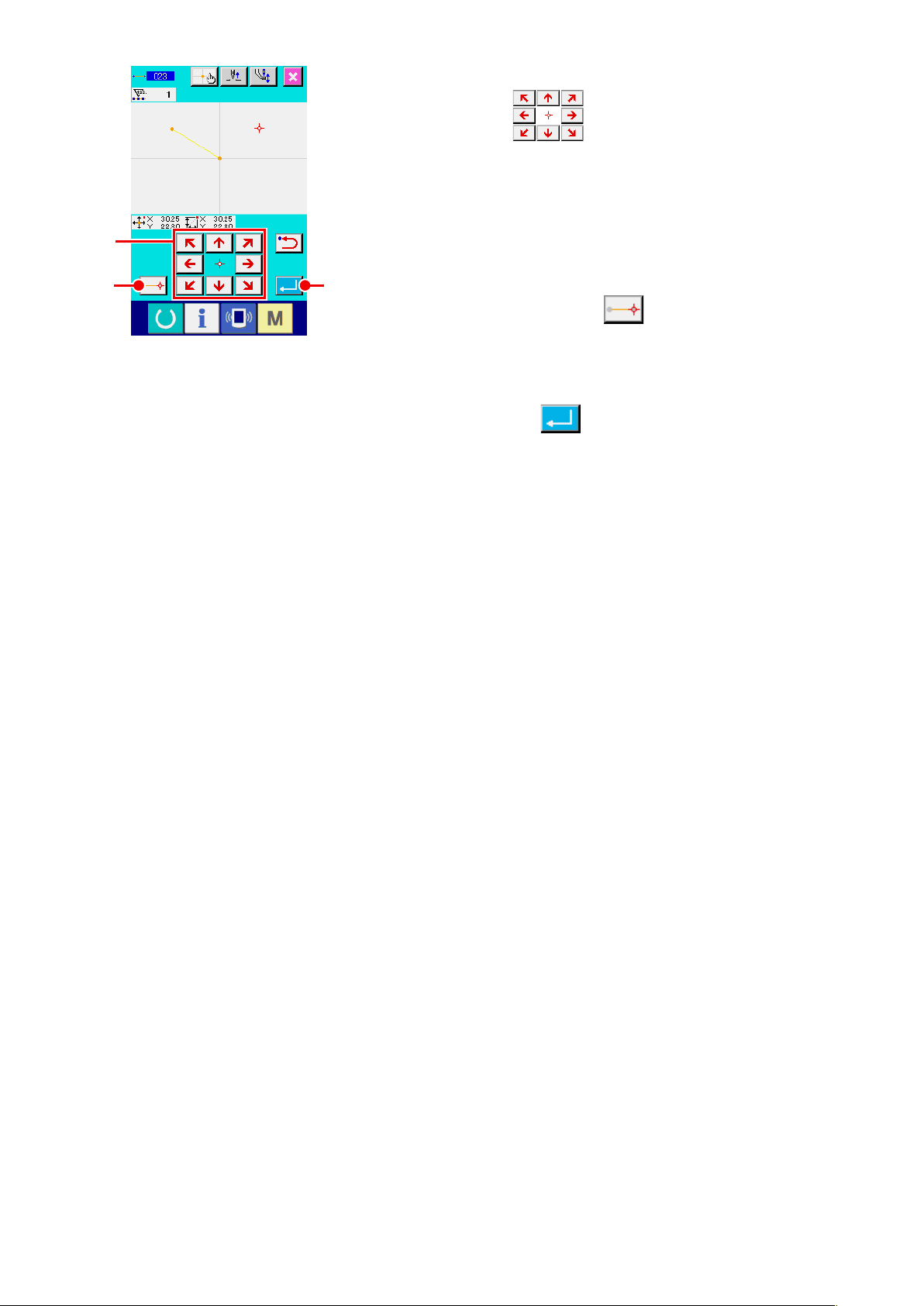
Move the needle position.
③
Press MOVE key G in the coordinate input screen,
and the needle position moves in the specied direction. While
MOVE key is held pressed, the needle position continuously
moves.
G
Input the coordinate.
④
When the needle position has moved to the specied position
IH
and DECIDING POINT button H is pressed, the position
is inputted as the shape point (passing point).
End the setting of linear ordinary sewing.
⑤
When ENTER button I is pressed, the set data is
inputted, and the screen returns to the standard screen.
It is possible to input by repeating the operation of steps ③
and ④ as well.
– 26 –
Page 31

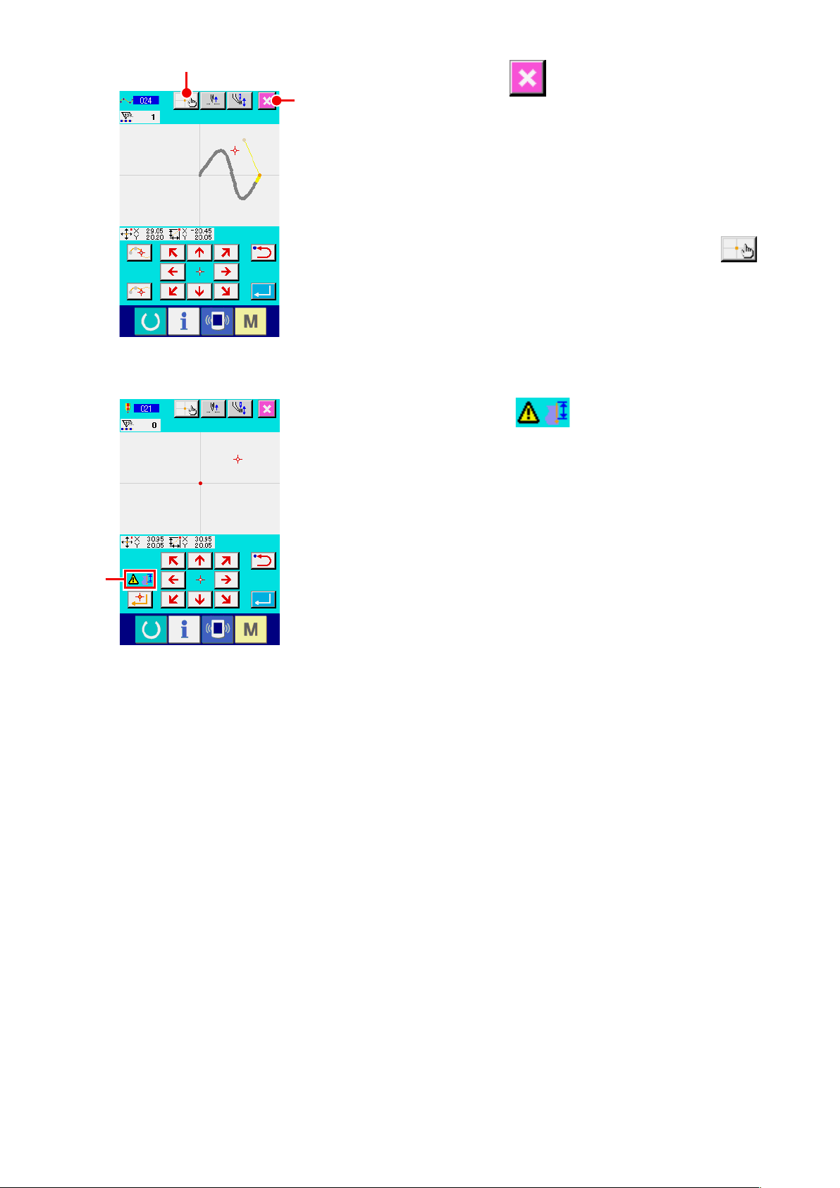
(3) Spline ordinary sewing (024)
It is possible to simply input the smooth curve using the spline ordinary sewing.
Display the spline ordinary sewing setting screen.
①
When selecting and executing SPLINE ORDINARY SEWING
B
A
(function code 024) in the code list screen, the spline
ordinary sewing setting screen is displayed.
Set the spline ordinary sewing.
②
The set value of present stitch length is displayed at STITCH
LENGTH INPUT button A, and the set value of
C
present sewing speed is displayed at SEWING SPEED INPUT
button B in the spline ordinary setting screen.
When the button of the item you desire to change the setting is
pressed, the input screen of the set value is displayed. Setting
procedure of stitch length and sewing speed is the same as
that of the linear ordinary sewing.
After setting or when it is not necessary to change, press
ENTER button C, and the coordinate input screen is
displayed.
Move the needle position.
③
E
D
F
Press MOVE key D in the coordinate input screen,
and the needle position moves in the specied direction.
Input the coordinate.
④
When the needle position has moved to the specied position,
press PASSING POINT button E, and the position is
G
inputted as the shape point (passing point).
Or, press DECIDING POINT button F, and the position
is inputted as the breakpoint.
For the breakpoint, refer to
ordinary sewing)" p.58
End the setting of spline ordinary sewing.
⑤
"4-9. Breakpoint (spline and
.
When ENTER button G is pressed, the set date is
inputted, and the screen returns to the standard screen.
DECIDING POINT button of the last point can be omitted.
It is possible to input by repeating the operation of steps ③
and ④ as well.
– 27 –
Page 32

1. In order to input the smooth shape of spline
ordinary sewing, the neat curve can be
obtained when selecting the input point
following the procedure below.
1) Select the top of input curve as the input
point. (❺ and ❾)
2) Making the points selected in step 1)
the center, select the points which are
separated a little before and after the
points in step 1). (❹, ❻, ❽, and )
3) Further, select the center of the section
having loose bulge as the input points. (❸,
, and )
❼
4)
Select the points near both ends and the
last point as the input points. (❷, , and )
❺
❹
❸
❷
❶
Input the input points selected by the steps above
❼
❽
❻
❾
in order. Also, be careful of the points below.
•
Take rather many input points at the sharp
curve and rather few ones at the gentle curve.
• Take 3 input points per curve at least.
2. Ellipse can be inputted using the spline
ordinary sewing.
1) Take the joint of the curve at the gentle
section of the curve.
2) Take the input points so as to be
symmetrical if possible.
– 28 –
Page 33

(4) Arc ordinary sewing (025)
When two points are specied, the arc connecting the points and the needle position is inputted as
the specied stitch length. Sewing direction is in the order of the specied points, and either clockwise
direction or counterclockwise one can be inputted.
Display the arc ordinary sewing setting screen.
①
When selecting and executing ARC ORDINARY SEWING
B
A
(function code 025) in the code list screen, the arc
ordinary sewing setting screen is displayed.
Perform setting of the arc ordinary sewing.
②
The set value of present stitch length is displayed at STITCH
LENGTH INPUT button A, and the set value of
C
present sewing speed is displayed at SEWING SPEED INPUT
button B in the arc ordinary sewing setting
screen.
When the button of the item you desire to change is pressed,
the input screen of the set value is displayed. Setting
procedure of stitch length and sewing speed is the same as
that of the linear ordinary sewing.
After setting or when it is not necessary to change, press
ENTER button C, and the coordinate input screen is
displayed.
D
E
Move the needle position.
③
Press MOVE key D in the coordinate input screen,
and the needle position moves in the specied direction.
Input the coordinate.
④
When the needle has moved to the specied position, press
DECIDING POINT button E, and the position is inputted
F
as the shape point (passing point).
Repeat the operation of the steps of ③ and ④ to input two
points. Two input points are necessary as the number of input
points. Also, it is not possible to input more than 3 points.
End setting of the arc ordinary sewing.
⑤
When ENTER button F is pressed, the set data is
inputted, and the screen returns to the standard screen.
DECIDING POINT button of the last point can be omitted.
– 29 –
Page 34

(5) Circle ordinary sewing (026)
When two points are specied, the circle connecting the points and the needle position is inputted as
the stitch length. Stitch direction is in the order of the specied points, and either clockwise direction or
counterclockwise one can be inputted.
Display the circle ordinary sewing setting screen.
①
When selecting and executing CIRCLE ORDINARY SEWING
B
A
(function code 026) in the code list screen, the circle
ordinary sewing setting screen is displayed.
Perform setting of the circle ordinary sewing.
②
The set value of present stitch length is displayed at STITCH
LENGTH INPUT button A, and the set value of
C
present sewing speed is displayed at SEWING SPEED INPUT
button B in the circle ordinary sewing setting
screen.
When the button of the item you desire to change is pressed,
the input screen of the set value is displayed. Setting
procedure of stitch length and sewing speed is the same as
that of the linear ordinary sewing.
After setting, or when it is not necessary to change, press
ENTER button C, and the coordinate input screen is
displayed.
D
E
Move the needle position.
③
Press MOVE key D in the coordinate input screen,
and the needle position moves in the specied direction.
Input the position.
④
When the needle position has moved to the specied position,
press DECIDING POINT button E, and the position is
F
inputted as the shape point.
Repeat the operation of the steps of ③ and ④ to input two
points. Two input points are necessary as the number of input
points. Also, it is not possible to input more than 3 points.
End setting of the circle ordinary sewing.
⑤
When ENTER button F is pressed, the set data is
inputted, and the screen returns to the standard screen.
DECIDING POINT button of the last point can be omitted.
– 30 –
Page 35

(6) Point sewing (021)
This function is used when direct inputting the needle entry point one stitch by one stitch.
Display the point sewing setting screen.
①
Press POINT SEWING button in the standard screen,
or select and execute POINT SEWING (function code 021)
in the code list screen, the point sewing setting
screen is displayed.
B
Perform setting of the point sewing.
②
The set value of present sewing speed is displayed at
C
SEWING PEED INPUT button B in the point
sewing setting screen.
When SEWING SPEED INPUT button is pressed, the sewing
speed input screen is displayed. Setting procedure of the
sewing speed is the same as that of the linear ordinary
sewing.
After setting, or when it is not necessary to change, press
ENTER button C, and the coordinate input screen is
displayed.
Move the needle position.
③
Press MOVE key D in the coordinate input screen,
and the needle position moves in the specied direction.
D
E
Input the coordinate.
④
When the needle position has moved to the specied position,
press DECIDING POINT button E, and the position is
F
inputted as the shape point.
It is possible to input by repeating the operation of steps ③
and ④ as well.
End setting of the point sewing.
⑤
When ENTER button F is pressed, the set data is
inputted, and the screen returns to the standard screen.
DECIDING POINT button of the last point can be omitted.
– 31 –
Page 36

(7) Ordinary sewing (022)
This function can input the linear ordinary sewing and the spline ordinary sewing.
Display the ordinary sewing setting screen.
①
Press ORDINARY SEWING button in the standard
B
A
screen, or select and execute ORDINARY SEWING (function
code 022) in the code list screen, and the ordinary
sewing setting screen is displayed.
Perform setting of the ordinary sewing.
②
The stitch length can be set with STITCH LENGTH INPUT
C
button A, and the sewing speed can be set with
SEWING SPEED INPUT button B in the
ordinary sewing setting screen.
When the button of the item you desire to change is pressed,
the input screen of the set value is displayed. Setting
procedure of the stitch length and the sewing speed is the
same as that of the linear ordinary sewing.
When ENTER button C is pressed, the coordinate input
screen is displayed.
Specify the position.
③
❸
❹
E
D
F
Press MOVE key D in the coordinate input screen,
❷
❶
and the needle position moves in the specied direction. When
DECIDING POINT button F is pressed, the shape point
of the linear ordinary sewing is inputted. When PASSING
POINT button E is pressed, the shape point of the
G
spline ordinary sewing is inputted.
(Refer to
p.58
End setting of the ordinary sewing.
④
"4-9. Breakpoint (spline and ordinary sewing)"
.)
When ENTER button G is pressed, the set data is
inputted, and the screen returns to the standard screen.
For example, when ❶, ❸ and ❹ are inputted with DECIDING
POINT button, and ❷ is inputted with PASSING POINT button,
a pattern as shown in the gure below is created.
❷
– 32 –
❸
❶
❹
Page 37

4-2. Zigzag sewing (030 to 033)
This function is the input function to create the needle entry point of zigzag in the lateral direction in
terms of the input reference line. It is convenient to perform inputting of zigzag sewing of wappen or the
like.
There are 4 kinds of zigzag sewings below.
• Linear zigzag sewing (function code 030)
• Spline zigzag sewing (function code 031)
• Arc zigzag sewing (function code 032)
• Circle zigzag sewing (function code 033)
Display the linear zigzag sewing setting screen.
①
When LINEAR ZIGZAG SEWING (function code 030)
E
D
C
A
is selected and executed in the code list screen, the
linear zigzag sewing setting screen is displayed.
B
G
Perform setting of the linear zigzag sewing.
②
F
The set value of present zigzag pitch is displayed at ZIGZAG
PITCH INPUT button A, the set value of present
H
zigzag width is displayed at ZIGZAG WIDTH INPUT button
B, and the set value of present sewing speed is
displayed at SEWING SPEED INPUT button C
in the linear zigzag sewing setting screen.
When the button of the item you desire to change is pressed,
the input screen of the set value is displayed. Setting
procedure in the input screen of each item is the same as that
of the linear ordinary sewing.
When the button for the item setting of which is to be changed
is pressed, the corresponding set value input screen is
displayed. The procedure for inputting a set value on the
corresponding item input screen is similar to that for the linear
ordinary sewing.
The position and direction to start zigzag sewing can be
selected using START DIRECTION button
F
or
. The button which is displayed in reverse
G
D
,
video represents the currently selected position and direction
to start zigzag sewing.
After setting, or when it is not necessary to change, press
ENTER button H, and the coordinate input screen is
displayed.
– 33 –
E
,
Page 38

I
J
Move the needle position.
③
When MOVE key I in the coordinate input screen
is pressed, the needle position moves in the specied
direction.
Input the coordinate.
④
When the needle position has moved to the specied position
K
and DECIDING POINT button J is pressed, the position
is inputted as the shape point (passing point).
It is possible to input by repeating the steps of ③ and ④ as
well.
End setting of the linear zigzag sewing.
⑤
When ENTER button K is pressed, the set data is
inputted, and the screen returns to the standard screen.
DECIDING POINT button of the last point can be omitted.
Setting procedure of the zigzag sewing of other shapes is the
same as that of the linear zigzag sewing.
Coordinate inputting procedure of the respective sewings is
the same as that of the ordinary sewing.
Zigzag sewing starting method list
No. Button
1
2
3
4
Type of direction to
start sewing
Leftward of the
center of stitch base
line
Rightward of the
center of stitch base
line
Leftward of the end
of stitch base line
Rightward of the end
of stitch base line
Description Example
Sewing is started from the left side toward
the direction of travel with the stitch base line
set at the center of zigzag width. Stitches are
produced in the zigzag form.
Sewing is started from the right side toward
the direction of travel with the stitch base line
set at the center of zigzag width. Stitches are
produced in the zigzag form.
Sewing is started from the left side with the
stitch base line set at the right end of zigzag
width toward the direction of travel.
Sewing is started from the right side with the
stitch base line set at the left end of zigzag width
toward the direction of travel.
– 34 –
Page 39

4-3. Offset sewing (034 to 037)
This is an input function to create the needle entry point which is separated an optional xed distance
in terms of the input reference line. It is convenient when inputting the needle entry point taking the
periphery of small thing as the reference when attaching the small things or the like.
There are 4 kinds of the offset sewings below.
• Linear offset sewing (function code 034)
• Spline offset sewing (function code 035)
• Arc offset sewing (function code 036)
• Circle offset sewing (function code 037)
Display the linear offset sewing setting screen.
①
When selecting and executing LINEAR OFFSET SEWING
D
C
A
(function code 034) in the code list screen, the linear
offset sewing setting screen is displayed.
B
E
Perform setting of the linear offset sewing.
②
The set value of present stitch length is displayed at STITCH
LENGTH INPUT button A, the set value of present offset
F
width is displayed at OFFSET WIDTH INPUT button B,
and the set value of present sewing speed is displayed at SEWING
SPEED INPUT button C in the linear offset sewing
screen.
When the button of the item you desire to change is pressed,
the set value is displayed in the input screen. Setting
procedure of the respective items in the input screen is the
same as that of the linear ordinary sewing.
Creation direction of the offset sewing can be specied with
CREATION DIRECTION buttons D and E. Button
or which is changed in color is the creation direction
which is selected now.
When CREATION DIRECTION, LEFT button D is pressed,
the offset sewing is created on the left side in terms of the
progressing direction and when CREATION DIRECTION, RIGHT
button E is pressed, the offset sewing is created on the right
side in terms of the progressing direction.
After setting, or when it is not necessary to change, press ENTER
button F, and the coordinate input screen is displayed.
– 35 –
Page 40

Move the needle position.
③
Press MOVE key G in the coordinate input screen,
and the needle position moves in the specied direction.
Input the coordinate.
④
When the needle position has move to the specied position,
G
H
❶
❹
❶'
press DECIDING POINT button H, and the position is
I
inputted as the shape point (passing point).
It is possible to input by repeating the steps of ③ and ④ as
well.
End setting of the linear offset sewing.
⑤
When ENTER button I is pressed, the set data is
inputted, and the screen returns to the standard screen.
DECIDING POINT button of the last point can be omitted.
Setting procedure of the offset sewing of other shapes is the
same as that of the linear offset sewing.
Inputting procedure of the coordinate of the respective sewings
is the same as that of the ordinary sewing.
1. Start the shape as shown in the left-hand
gure from the position of ❶, and input in
❷
the order of
❷→❸→❹→❶
. Then the pattern
as shown in the broken line is created.
When starting not the corner of polygon as ❶
but starting from the side as ❶’, a neat offset
❸
sewing can be created.
2. Input a shape that one line is formed from the
start point to the end point of input.
3. In case of arc or circle, when the width is
made larger than the radius of circle, the
pattern which is against expectation is
created. So, be careful.
– 36 –
Page 41

4-4. Double sewing
This is an input function to create the needle entry point to the point which is separated an optional xed
distance in terms of the input reference line.
(1) Double orderly sewing (040 to 043)
Create the sewing so that the sewing composed with the input points and that of the offset gure are in
the same direction. There are 4 kinds of double orderly sewings below.
• Linear double orderly sewing (function code 040)
• Spline double orderly sewing (function code 041)
• Arc double orderly sewing (function code 042)
• Circle double orderly sewing (function code 043)
Display the linear double orderly sewing setting screen.
①
When selecting and executing LINEAR DOUBLE ORDERLY
D
C
A
SEWING (function code 040) in the code list screen,
the linear double orderly sewing setting screen is displayed.
B
E
Perform setting of the linear double orderly sewing.
②
The set value of present stitch length is displayed at STITCH
LENGTH INPUT button A, the set value of present
F
double sewing width is displayed at DOUBLE SEWING WIDTH
INPUT button B , and the set value of present
sewing speed is displayed at SEWING SPEED INPUT button
C in the linear double orderly sewing setting screen.
When the button of the item you desire to change is pressed,
the input screen of the set value is displayed. Setting
procedure in the input screen of the respective items is the
same as that of the linear ordinary sewing.
Creating direction of the double sewing can be specied
with CREATING DIRECTION buttons D and
. Button or which is changed in color is the
E
creating direction which is selected now. When CREATION
DIRECTION, LEFT button D is pressed, the double
sewing is created on the left-hand side in terms of the
progressing direction, and CREATING DIRECTION, RIGHT
E is pressed, the double gure is created on the right-
hand side in terms of the progressing direction.
After setting, or when it is not necessary to change, press ENTER
button F, and the coordinate input screen is displayed.
– 37 –
Page 42

Move the needle position.
③
Press MOVE key G in the coordinate screen, and
the needle position moves in the specied direction.
Input the coordinate.
④
When the needle position has moved to the specied position
G
H
and DECIDING POINT button H is pressed, the position
I
is inputted as the shape point (passing point).
It is possible to input by repeating the steps of ③ and ④ as
well.
End setting of the linear double orderly sewing.
⑤
When ENTER button I is pressed, the set data is
inputted, and the screen returns to the standard screen.
DECIDING POINT button of the last point can be omitted.
Setting procedure of the double orderly sewings of other
shapes is the same as that of the linear double orderly sewing.
Coordinate inputting procedure of the respective sewings is
the same as that of the ordinary sewing.
In case of arc or circle, when the width is made
larger than the radius of circle, the pattern which
is against expectation is created. So, be careful.
– 38 –
Page 43

(2) Double reverse sewing (044 to 047)
Create the sewing so that the sewing composed at the input point and that of the offset gure are in the
reverse direction.
There are 4 kinds of the double reverse sewings below.
• Linear double reverse sewing (function code 044)
• Spline double reverse sewing (function code 045)
• Arc double reverse sewing (function code 046)
• Circle double reverse sewing (function code 047)
Display the linear double reverse sewing setting screen.
①
When selecting and executing LINEAR DOUBLE REVERSE
SEWING (function code 044) in the code list screen,
the linear double reverse sewing setting screen is displayed.
Setting procedure of the double reverse sewing is the same as
that of the double orderly sewing.
Difference between orderly sewing and reverse
sewing
❸
❶
Sewing in case of orderly sewing
❸
❶
Sewing in case of reverse sewing
is inputting point, and ❸ is the last point.
❶
❷
❷
In case of arc or circle, when the width is made
larger than the radius of circle, the pattern which
is against expectation is created. So, be careful.
– 39 –
Page 44

(3) Overlapped reverse sewing (050 to 053)
Sewing of the gure composed at the input point and that which returns it reversely are created.
There are four different types of overlapped reverse sewing as described below:
• Linear overlapped reverse sewing (function code 050)
• Spline overlapped reverse sewing (function code 051)
• Arc overlapped reverse sewing (function code 052)
• Circle overlapped reverse sewing (function code 053)
Displaying the linear overlapped reverse sewing setting
①
screen
When selecting and executing LINEAR OVERLAPPED
A
REVERSE SEWING (function code 050) on the
code list screen, the linear overlapped reverse sewing setting
screen is displayed.
B
Performing setting of the linear overlapped reverse
②
C
sewing
On the linear overlapped reverse sewing setting screen,
the current set value of stitch length is indicated on STITCH
LENGTH INPUT button A and the current set value
of speed of stitch is indicated on SPEED OF STITCH INPUT
button B.
When the button of the item you desire to change is pressed,
the input screen of the set value is displayed. Setting
procedure of stitch length and sewing speed is the same as
that of the linear ordinary sewing.
After setting, or when it is not necessary to change, press
ENTER button C, and the coordinate input screen is
displayed.
– 40 –
Page 45

Move the needle position.
③
Press MOVE key D in the coordinate input screen,
and the needle position moves in the specied direction.
Input the coordinate.
④
When the needle position has moved to the specied position,
D
E
and DECIDING POINT button E is pressed, the position
F
is inputted as the shape point (passing point).
It is possible to input by repeating the steps of ③ and ④ as
well.
End setting of the linear reverse sewing.
⑤
When ENTER button F is pressed, the set data is
inputted, and the screen returns to the standard screen.
DECIDING POINT button of the last point can be omitted.
Setting procedure of the reverse sewings of other shapes is
the same as that of the linear reverse sewing.
– 41 –
Page 46

4-5. Machine control command
Machine control command inputs various control commands to the present point.
(1) Thread trimming (001)
Thread trimming can be optionally performed on the way of pattern data.
Select thread trimming.
①
When selecting and executing THREAD TRIMMING (function
code 001) in the code list screen, the left-hand
screen is displayed.
Input thread trimming.
②
When ENTER button A is pressed in the left-hand
screen, thread trimming is inputted, and the screen returns to
A
the standard screen.
(2) The 2nd origin (002)
This function can set the 2nd origin between the origin and the sewing start point, and specify the
needle position before the start of sewing motion. 2nd origin can be set only on the way of jump feed.
Set the present needle position to one point on the pattern
①
of jump feed.
Select the 2nd origin.
②
When selecting and executing 2ND ORIGIN (function code 002)
in the code list screen, the left-hand screen is displayed.
Input the 2nd origin.
③
A
When ENTER button A is pressed in the right-hand
screen, the 2nd origin is inputted, and the screen returns to
the standard screen.
2nd origin
When 2nd origin is set at ❸ of the jump feed section in the
left-hand gure, the feed stops at ❸ after jump feed of ❶ → ❷
❺
, then the sewing machine performs the cycle operation
→ ❸
of ❸ through ❾.
❷
❶
❽
❸
❹
❾
❼
Origin
This function has to set the present needle
❻
position to one point on the pattern of jump feed
beforehand. When enlarging or reducing the
pattern, the route from the origin to the 2nd origin
is not enlarged or reduced.
– 42 –
Page 47

(3) Stop (003)
This function inputs the Stop command.
①
When selecting and executing STOP (function code 003)
Select the Stop.
in the code list screen, the left-hand screen is
B
C
displayed.
Specify the stop state.
②
The presser state at the time of stop is displayed at PRESSER
STATE SETTING button B, and the needle position
A
at the time of stop is displayed at NEEDLE POSITION
SETTING button C.
To specify the state, press the buttons of PRESSERSTATE
SETTING button B and of NEEDLE POSITION
SETTING button C, and display the setting screen.
Input the Stop.
③
When ENTER button A is pressed in the left-hand
D
screen, the stop is inputted with the set contents, and the
screen returns to the standard screen.
When performing stop after thread trimming,
input in the order of thread trimming and stop.
Perform setting of the presser state.
④
When PRESSER STATE SETTING button B is
pressed, the presser state setting screen is displayed.
The presser position at the time of stop can be selected from D.
The selected button is changed in color. When ENTER button
E is pressed, the selected contents are inputted, and
the screen returns to the stop setting screen.
E
Button display Stop position
Presser lifting position
Presser lowering position
– 43 –
Page 48

Perform setting of the needle position.
⑤
When NEEDLE POSITION SETTING button C is
F
C
pressed, the needle position setting screen is displayed.
The needle position at the time of stop can be selected from F.
The selected button is changed in color. When ENTER button
G is pressed, the selected contents are inputted, and
the screen returns to the stop screen.
Button display Stop position
Upper dead point
UP position
DOWN position
UP position error will be produced at the time of
G
sewing when the needle position is set to DOWN
position at the end of sewing or before jump feed.
Needle stop instructions become invalid when
the sewing machine is in the stop state, and the
needle position does not change.
(4) One revolution of sewing machine (006)
This function inputs one revolution of sewing machine command.
Select one revolution of sewing machine.
①
When selecting and executing ONE REVOLUTION OF
SEWING MACHINE (function code 006) in the code
list screen, the left-hand screen is displayed.
Input one revolution of sewing machine.
②
When ENTER button A is pressed in the left-hand
screen, one revolution of sewing machine is inputted, and the
A
screen returns to the standard screen.
This function, combined with jump feed, is used
for basting or the like.
– 44 –
Page 49

(5) Mark 1 and mark 2 (008, 009)
These functions put marks in the pattern.
Select mark 1 and mark 2.
①
When selecting and executing MARK 1 (function code 008)
Input the mark 1.
②
When ENTER button A is pressed in the left-hand
A
For the operation of the sewing machine in terms
and MARK 2 (function code 009) in the
code list screen, the left-hand screen is displayed.
screen, the mark 1 is inputted, and the screen returns to the
standard screen.
of mark 1 and mark 2, refer to the Engineer's
Manual.
(6) Thread tension controller No. 3 (007)
This function inputs the thread tension controller No. 3 command.
Select the thread tension controller No. 3.
①
When selecting and executing THREAD TENSION
CONTROLLER NO. 3 (function code 007) in the
code list screen, the left-hand screen is displayed.
Input the thread tension controller No. 3.
②
When ENTER button A is pressed in the left-hand
screen, the thread tension controller No. 3 is inputted, and the
A
screen returns to the standard screen.
– 45 –
Page 50

(7) Delay (010)
This function can set the external output time or the like.
Select the delay.
①
When selecting and executing DELAY (function code 010)
in the code list screen, the left-hand screen is
displayed.
Input the delay value.
A
②
When the delay value is set with TEN key to A
C
and + or - button B in the left-hand screen, and
ENTER button C is pressed, the delay is inputted with
the set value, and the screen returns to the standard screen.
B
For the operation of the sewing machine in case
of setting, refer to the Engineer's Manual.
(8) External input (011)
This function performs waiting for signal from input terminal of the sewing machine main unit.
Select the external input.
①
When selecting and executing EXTERNAL INPUT (function
code 011) in the code list screen, the left-hand
A
B
screen is displayed.
Perform setting of the input terminal No.
②
Set the terminal No. to which input is performed with TEN key
to A and + or - button B in the left-
C
hand screen, and press ENTER button C. Then external
input is inputted, and the screen returns to the standard
screen.
For the terminal No. and the operation of the
sewing machine, refer to the Engineer's Manual.
– 46 –
Page 51

(9) External output (012)
This function can send signal to the external terminal of the sewing machine main unit.
Select the external output.
①
When selecting and executing EXTERNAL OUTPUT (function
code 012) in the code list screen, the left-hand
screen is displayed.
Perform setting of the output terminal No.
A
B
②
Set the terminal No. to which output is performed with TEN
key to A and + or - button B in the
C
left-hand screen, and press ENTER button C. Then
external output is inputted, and the screen returns to the
standard screen.
For the terminal No. and the operation of the
sewing machine, refer to the Engineer's Manual.
– 47 –
Page 52

(10) Enlargement/reduction reference point (004)
Enlargement/reduction reference point can be inputted at the optional position of the created pattern
data. When the enlargement/reduction reference point is not set, taking the origin as the reference,
enlargement/reduction is performed.
Select the enlargement/reduction reference point.
①
When selecting and executing ENLARGEMENT/REDUCTION
REFERENCE POINT (function code 004) in the
code list screen, the left-hand screen is displayed.
Perform setting of the enlargement/reduction reference
②
point.
When ENTER button A is pressed in the left-hand
A
screen, the enlargement/reduction reference point is inputted,
and the screen returns to the standard screen.
1. When enlargement/reduction reference points
are inputted more than two times, the last
inputting is effective.
2. When executing this function, set the
present needle position to the position of the
reference beforehand.
When enlarging /reducing at the time of the
pattern reading, the enlargement/reduction is
performed taking the enlargement/reduction
reference point as the reference. Also, similarly
at the time of sewing, the enlargement/reduction
is performed taking the enlargement/reduction
reference point as the reference.
Reference point
Enlargement with
reference point setting
– 48 –
Enlargement without
setting
Page 53

(11) Inversion point (005)
Inversion point can be inputted only when the inversion state is set to the optional inversion at clamp
inversion setting (
"9-2. Clamp inversion setting (091)" p.96
Select the inversion point.
①
When selecting and executing INVERSION POINT (function
code 005) in the code list screen, the left-hand
screen is displayed.
Perform setting of the inversion point.
②
When ENTER button A is pressed in the right-hand
screen, the inversion point is inputted to the present needle
A
position, and the screen returns to the standard screen.
When inversion point is inputted to the position of ❺ as shown
in the below gure, the linear sewing operation is performed
in the order of ❸ → ❹ → ❺ (inversion) → ❻ → ❼ → ❸ after
jump feed from the origin to ❸.
).
❼
❻
❸
Origin
❷
❹
Inversion point
❺
❶
1. Inversion clamp is in the state of left-hand
at the start of sewing, and repeats left-hand
state and right-hand state alternately at each
time of inversion command. Accordingly it
is necessary to surely input the inversion
command with odd numbers, In case of even
numbers, the clamp and needle interfere with
each other at the end of sewing, and needle
may break.
2. It is not possible to set the inversion point at
the positions below.
(a) Immediately after the 2nd origin
(b) Immediately after thread trimming
– 49 –
Page 54

(12) Thread tension setting (014)
The value of the thread tension is set. This value is valid up to the place where there is the next thread
tension setting command.
Select the thread tension setting.
①
When selecting and executing THREAD TENSION SETTING
(function code 014) in the code list screen, the left-
hand screen is displayed.
Set the value of thread tension.
A
B
②
Set the value of thread tension with TEN key to
, and + or - button B in the left-hand screen and
C
A
press ENTER button C. Then the value of the set thread
tension is inputted, and the screen returns to the standard
screen.
The value which is really inputted as the command is :
Thread tension setting (No. 014) = Thread tension reference
value (No. 113) + value to be inputted to the data (increase/
decrease value)
When "50" is set with thread tension reference
value (No. 113) and "100" is set with thread tension
setting (No. 014), the value to be inputted to the
data (increase/decrease value) becomes "50".
– 50 –
Page 55

(13) Intermediate presser height setting (018)
The intermediate presser height is set. This value is effective up to the position where the next
intermediate presser height setting command exists.
Select the intermediate presser height setting.
①
When selecting and executing INTERMEDIATE PRESSER
HEIGHT SETTING (function code 018) in the code
list screen, the left-hand screen is displayed.
Perform setting of the intermediate presser height.
A
B
②
Set the value of thread tension with TEN key to
, and + or - button B in the left-hand screen and
C
A
press ENTER button C. Then the value of the set thread
tension is inputted, and the screen returns to the standard
screen.
When + or - button B is pressed with the
intermediate presser lowered, the intermediate presser
interlocks and becomes the inputted height.
The value which is really inputted as the command is :
Intermediate presser height setting (No. 018) = Intermediate
presser height reference value (No. 115) + value to be inputted
to the data (increase/decrease value)
1. When "1.0 mm" is set with intermediate
presser height reference value (No. 115) and
"3.0 mm" is set with intermediate presser
height setting (No. 018), the value to be
inputted to the data (increase/decrease value)
becomes "2.0 mm".
2. Input can be performed up to 7 mm. However,
the actual operation is limited by the setting
of the sewing machine.
– 51 –
Page 56

(14) Area Classication (016)
Area Classication command is inputted.
Select the area Classication.
①
When selecting and executing AREA CLASSIFICATION
Input the area Classication.
②
When ENTER button A is pressed in the right-hand
(function code 016) in the code list screen, the left-
hand screen is displayed.
A
screen, the area Classication command is inputted, and the
screen returns to the standard screen.
For the operation of the sewing machine in case
of setting, refer to the Engineer's Manual.
– 52 –
Page 57

(15) Sewing machine stop (019)
Sewing machine stop command is inputted.
Select the sewing machine stop.
①
When selecting and executing SEWING MACHINE STOP
(function code 019) in the code list screen, the left-
A
hand screen is displayed.
Specify the stop state.
②
Select the needle position at the time of stop from among A.
The color of the selected button is changed .
B
Input the sewing machine stop.
③
When ENTER button B is pressed in the left-hand
screen, stop command is inputted, and the screen returns to
the standard screen.
Button display Stop position
Upper dead point
UP position
DOWN position
UP position error will be produced at the time of
sewing when the needle position is set to DOWN
position at the end of sewing or before jump feed.
Needle stop instructions become invalid when
the sewing machine is in the stop state, and the
needle position does not change.
– 53 –
Page 58

(16) Machine control command deletion (059)
Machine control command of the present position (2nd origin, stop, thread trimming, thread tension set
value, intermediate presser height setting, etc.) is deleted.
Select the machine control command deletion.
①
When selecting and executing MACHINE CONTROL
COMMAND DELETION (function code 059) in the
code list screen, the left-hand screen is displayed.
Execute the machine control command deletion.
②
When ENTER button A is pressed in the left-hand
(17) Sewing speed (092)
Sewing speed is inputted.
A
screen, the machine control command is deleted, and the
screen returns to the standard screen.
Select the sewing speed.
①
When selecting and executing SEWING SPEED (function
code 092) in the code list screen, the left-hand
screen is displayed.
A
B
Set the sewing speed.
②
Set the sewing speed with TEN key to A and +
C
or - button B in the left-hand screen, and press
ENTER button C. Then the sewing speed is inputted
with the set value, and the screen returns to the standard
screen.
– 54 –
Page 59

4-6. Automatic back-tack (064)
Back-tack of Z type or V type of the specied number of stitches is created to the start of sewing, the
end of sewing, or the both of the element including the present point.
Select the automatic back-tack.
①
When selecting and executing AUTOMATIC BACK-TACK
(function code 064) in the code list screen, the
A
B
C
D
automatic back-tack setting screen is displayed.
Perform setting of the automatic back-tack.
②
The set value of present number of stitches at the start of
sewing is displayed at NUMBER OF STITCHES AT THE
F
G
E
START OF SEWING SETTING button A, and the
set value of present number of stitches at the end of sewing
is displayed at NUMBER OF STITCHES AT THE END OF
SEWING SETTING button B in the automatic back-
tack setting screen.
When the button of the item you desire to change is pressed,
the input screen of the set value is displayed. When the
number of stitches is set with TEN key to F, and
+ or - buttons G in the number of stitches setting
screen, press ENTER button H. Then the set number
H
of stitches is inputted, and the screen returns to the automatic
back-tack screen.
The type of back-tack can be specied with BACK-TACK
TYPE SELECTION buttons C and D. The button
which is changed in color is the type which is
selected now. When V TYPE button C is pressed, V
type back-tack is created, and when Z type button D is
pressed, Z type back-tack is created.
After setting, or when it is not necessary to change, press
ENTER button E in the automatic back-tack setting
screen. Then the back-tack is created, and the screen returns
to the standard screen.
– 55 –
Page 60

4-7. Condensation sewing (065)
The specied number of stitches of the start of sewing, the end of sewing, or the both of the element
including the present point is changed to the specied pitch.
Select the condensation sewing.
①
When selecting and executing CONDENSATION SEWING
(function code 065) in the code list screen, the
A
B
E
F
condensation sewing setting screen is displayed.
C
Perform setting of the condensation sewing.
②
The set value of present number of stitches at the start of
sewing is displayed at NUMBER OF STITCHES AT THE
D
START OF SEWING SETTING button A, the set
value of present number of stitches at the end of sewing
is displayed at NUMBER OF STITCHES AT RHE END OF
SEWING SETTING button B, and the set value of
present pitch is displayed at PITCH SETTING button
in the condensation sewing setting screen.
C
When the button of the item you desire to change is pressed,
the input screen of the set value is displayed. Set the value
with TEN key to E and + or - buttons
in the input screen, and press ENTER button G.
F
G
Then the set value is inputted, and the screen returns to the
condensation sewing setting screen.
When “0” is set as the number of stitches, condensation
sewing of the part can be specied without the condensation
sewing.
After setting, or when it is not necessary to change, press
ENTER button D in the condensation sewing setting
screen. Then the condensation sewing is created, and the
screen returns to the standard screen.
– 56 –
Page 61

4-8. Overlapped sewing (066)
Overlapped sewing data of the specied number of stitches is created after the present point.
Select the overlapped sewing.
①
When selecting and executing OVERLAPPED SEWING
(function code 066) in the code list screen, the
overlapped sewing setting screen is displayed.
Perform setting of the overlapped sewing.
②
When FEED BACKWARD button A or FEED
A
C
B
D
FORWARD button B is pressed, the needle entry point
can be traced. The present needle position is displayed in
red. When DECIDING POINT button C is pressed, the
needle position becomes the object of overlapped sewing
which is displayed in pink. When ENTER button D
is pressed, the overlapped sewing element which is set as
the object is created, and the screen returns to the standard
screen.
– 57 –
Page 62

4-9. Breakpoint (spline and ordinary sewing)
The breakpoint is the point where two points of the shape point
D
❷
of spline sewing are overlapped, and shows the termination of
❶
one spline curve. The point where ENTER button C and
❸
❺
DECIDING POINT button B are pressed with the input of
❹
spline sewing becomes the breakpoint.
A
B
Input the breakpoint in the spline ordinary sewing.
①
Select the spline ordinary sewing (function code 024) in
C
the code list screen, and perform the coordinate input of
the spline ordinary sewing. Input points ❶, ❷ and ❹ with
PASSING POINT button A and point ❸ and point ❺
with DECIDING POINT button B, and press ENTER
button C at point ❺. Points ❸ and ❺ become the
breakpoints, and the number of input shape points display D
is added by two.
The result is as shown in the gure below. The spline curve
ends once at point ❸ where the breakpoint is inputted, and a
new spline curve is formed up to the next breakpoint ❺. (As
the element, one spline sewing is performed.)
❶
❸
❷
❺
❹
– 58 –
Page 63

❸
❷
❶
❹
A
Input the breakpoint in the ordinary sewing.
②
For the ordinary sewing, the point to be inputted is determined
❺
according to the kind of element immediately before the point
where DECIDING POINT button B is pressed.
❼
Select ORDINARY SEWING (function 022) , and
❻
input points ❶, ❷, ❺ and ❼ with DECIDING POINT button
B and points ❸, ❹ and ❻ with PASSING POINT
B
❷
❶
R
button A in the cordinate input screen.
In this case, point ❷ becomes the normal deciding point
(number of shape points + 1) since the point that is one before
point ❷ is the linear sewing, and point ❺ and point ❼ become
the breakpoints (number of shape points + 2) since the point
before the points ❺ and ❼ is the spline sewing.
❸
❷
❶
❹
Perform modication of the shape point with the
③
❺
❼
❻
breakpoint.
❸
It is necessary to be careful when performing the modication
❺
❹
of the shape point (
since the breakpoint is the point where the shape point is
"5-8. Shape point modication" p.75
overlapped twice.
)
Select SHAPE POINT MOVE (function code 136)
D
, and select the shape point to be moved. Press FEED
FORWARD button D and advance the shape point to
be selected. Then you will nd that there are two points of the
shape point at the breakpoint (point R).
– 59 –
Page 64

R
When you desire to move point R to point S, the result will be
changed by selecting either shape point of rear ❷ or front ❸.
The result when point of rear ❷ has been moved.
❸
❷
❺
❷
❶
S
❶
❸
❹
The result when point of front ❸ has been moved.
❺
❹
❷
❸
❺
❶
❹
Point R can be moved by moving both point of rear ❷ and
point of front ❸ to the same coordinates.
R
❷
❸
❺
❹
❶
When performing the shape point deletion of either point of
rear ❷ or point of front ❸, the breakpoint becomes the normal
passing point and the continuous spline sewing is formed.
❸
❺
❶
– 60 –
❹
Page 65

5. MODIFICATION OF THE PATTERN
To perform the modication of the pattern, move the needle position to the modifying position using be-
forehand FEED BACKWARD key or FEED FORWARD key in the standard screen.
5-1. Point modication
(1) Point deletion (070 and 074)
The pattern data of the specied section is deleted in needle entry point unit. There are two methods of
RELATIVE POINT DELETION AND ABSOLUTE POINT DELETION depending on
moving of the pattern data after the deleted point.
Point deletion can delete not only the pattern data which is created with point sewing input, but also the
data inputted with any function such as linear sewing or the like.
Select the relative point deletion.
①
Select and execute RELATIVE POINT DELETION (function
B
code 070) in the code list screen.
Specify the relative point deletion range.
②
Move the needle position and specify the section of the deleting
points by pressing FEED BACKWARD key B or FEED
C
D
FORWARD key C, and press ENTER button D.
Conrm the point change.
③
The point change conrmation screen shows that the point
change may be changed to the point sewing. In case of con-
tinuing, press ENTER button A, and the point deletion
conrmation screen is displayed.
A
– 61 –
Page 66

Execute the relative point deletion.
④
When ENTER button E is pressed in the point deletion
conrmation screen, the point deletion is executed, and the
screen returns to the standard screen.
In case of the relative point deletion, the whole pattern data
after the deleted point moves while holding the relation before
deletion.
E
Deletion
❶ ❷ ❸ ❹ ❶ ❸ ❹
Relative point deletion
In case of the absolute point deletion, select and execute AB-
SOLUTE POINT DELETION (function code 074) in the
code list screen. In this case, the pattern data after the deleted
point does not move.
❶ ❷ ❸ ❹ ❶ ❸ ❹
Deletion
Absolute point deletion
1. As the result of deleting the point, be careful
that the distance of change does not exceed
the maximum stitch length of the sewing ma-
chine.
2. As the result of deleting the point, there is a
case where a part of the created pattern ex-
ceeds the sewing area.
In such a case as this, modify the pattern
data so that it is put within the sewing area
using the modication function.
– 62 –
Page 67

(2) Point move (071 and 075)
This function moves the specied needle entry point. There are two methods of RELATIVE POINT
MOVE and ABSOLUTE POINT MOVE depending on moving of the pattern data
after the moved point.
The point move can move not only the pattern data created with the point sewing input, but also the
data inputted with any function such as linear sewing or the like. In case of the linear sewing or the like,
when the point move is executed, it is changed to the point sewing.
Select the relative point move.
①
Select and execute RELATIVE POINT MOVE (function code
071) in the code list screen.
Specify the relative point move position.
②
Specify the move position of the point using MOVE key
B
B, and press ENTER button C.
C
Conrm the point change.
③
The point change conrmation screen shows that the point
change may be changed to the point sewing. In case of continu-
ing, press ENTER button A, and the point move is exe-
cuted. Then the screen returns to the standard screen.
A
Execute the relative point move.
④
When ENTER button D is pressed in the relative point
conrmation screen, the point moce is executed, and the screen
returns to the standard screen.
D
– 63 –
Page 68

In case of the relative point move, the whole pattern data after
the moved point moves while holding the previous relation.
Move
Relative point move
In case of the absolute point move, select and execute ABSO-
LUTE POINT MOVE (function code 075) in the code
list screen.
In this case, the pattern data after the moved point does not
move.
Move
Absolute point move
1. After the result of moving the point, be care-
ful that the distance of change does not ex-
ceed the maximum stitch length of the sew-
ing machine.
2. As the result of moving the point, there is a
case where a part of the created pattern data
exceeds the sewing area.
In such a case as this, modify the pattern
data so that it is put within the sewing area
using the modication function.
– 64 –
Page 69

(3) Point adding (076)
A
The point is added after the specied needle entry point. The pat-
tern data after the added point does not move. Point adding can be
added to not only the pattern data created with the input of point
sewing, but also the data inputted with any function such as linear
sewing or the like.
Select the absolute point adding.
①
Select and execute ABSOLUTE POINT ADDING (function code
B
076) in the code list screen.
Specify the absolute point adding position.
②
Specify the adding position of the point using MOVE key
A, and press ENTER button B.
Adding
Needle position
Absolute point adding
Conrm the absolute point adding.
③
The point change conrmation screen shows that the point
change may be changed to the point sewing. In case of continu-
ing, press ENTER button C, and the point move is exe-
cuted. Then the screen returns to the standard screen.
C
– 65 –
Page 70

Execute the absolute point adding.
④
When ENTER button D is pressed in the absolute point
adding conrmation screen, point adding is executed and the
screen returns to the standard screen.
1. As the result of adding the point, be careful
that the distance of change does not exceed
D
the maximum stitch length of the sewing ma-
chine.
2. As the result of adding the point, there is a
case where a part of the created pattern data
exceeds the sewing area.
In such a case as this, modify the pattern
data so that it is put within the sewing area
using the modication function.
– 66 –
Page 71

5-2. Vertex modication
(1) Vertex deletion (072 and 077)
T
his function deletes one specied vertex of the pattern data. There are two methods of RELATIVE
VERTEX DELETION and ABSOLUTE VERTEX DELETION depending on moving of
the pattern data after the deleted point.
This function cannot be executed when the specied point is the needle entry point other than the ver-
tex of the element.
Select the relative vertex deletion.
①
When selecting and executing RELATIVE VERTEX DELETION
(function code 072) in the code list screen, the relative
vertex deletion conrmation screen is displayed.
Execute the relative vertex deletion.
②
When ENTER button A is pressed in the relative vertex
A
cuted, and the screen returns to the standard screen.
❶
Relative vertex deletion
❷
❸
Deletion
❶
❸
In case of the relative vertex deletion, the whole pattern data after
the deleted point moves while holding the relation before deletion.
deletion conrmation screen, the relative vertex deletion is exe-
❶
❷
Deletion
❶
❸
Absolute vertex deletion
❸
In case of the absolute vertex deletion, select and execute AB-
SOLUTE VERTEX DELETION (function code 077) in
the code list screen.
In this case, the pattern data after the deleted point does not move.
As the result of deleting the point, there is a case
where a part of the created pattern data exceeds
the sewing area. In such a case as this, modify
the pattern data so that it is put within the sewing
area using the modication function.
– 67 –
Page 72

(2) Vertex move (073 and 078)
This function moves the specied needle entry point. There are two methods of RELATIVE VERTEX
MOVE and ABSOLUTE VERTEX MOVE depending on moving of the pattern data
In case of the relative vertex move : This function cannot be executed when the specied point the needle entry
point other than the vertex.
In case of the absolute vertex move : This function cannot be executed when the specied point is the last needle
entry point of the element or the needle entry point other than the vertex.
Select the relative vertex move.
①
Select and execute RELATIVE VERTEX MOVE (function code
073) in the code list screen.
Specify the relative vertex move position.
②
Specify the moving position of the vertex using MOVE key
B in the relative vertex move position specifying
B
screen, and press ENTER button C. Then the machine
C
control command deletion conrmation screen is displayed.
When the is pressed on the machine con-
trol command deletion conrmation screen, the
machine control command information recorded
for needle entry points are deleted.
Information on thread trimming, external output,
thread tension setting, sewing machine stopping,
sewing speed delay, 2nd origin, pause and sewing machine rotation are deleted.
Execute the vertex move.
③
When ENTER button A is pressed in the machine control
command deletion conrmation screen, the vertex move is executed, and the screen returns to the standard screen.
A
Relative vertex move
In case of the relative vertex
move, the whole pattern data
after the moved point moves
while holding the relation before moving.
Move
Absolute vertex move
In case of the absolute vertex
move, select and execute ABSOLUTE VERTEX MOVE (function
code 078) .
In case of the absolute vertex
Move
move, the pattern data after the
moved point does not move.
As the result of moving the point, there is a case where a part of the created pattern
data exceeds the sewing area.
In such a case as this, modify the pattern data so that it is put within the sewing
area using the modication function.
– 68 –
Page 73

5-3. Element deletion (063)
This function deletes sewing element and machine command in terms of element.
All elements after deletion move so as to advance as many as the deleted elements.
Display the element deletion executing screen.
①
When pressing ELEMENT DELETION button A in the
standard screen, or selecting and executing ELEMENT DELE-
TION (function code 063) in the code list screen, the
element deletion executing screen is displayed.
A
Execute the element deletion.
②
When ENTER button B is pressed in the element dele-
tion screen, the element deletion is executed, and the screen
returns to the standard screen.
When the elements to which the present needle position be-
longs are deleted, the whole pattern data after the deleted ele-
ments moves so as to advance, and the needle position moves
to the sewing end point of the element immediately before the
B
deleted elements.
Present needle
position
– 69 –
Element deletion
Needle position
after deletion
Page 74

5-4. Jump feed speed change (060)
Jump feed speed can be changed to the created jump feed element in terms of element.
Display the jump feed speed change setting screen.
①
When selecting and executing JUMP FEED SPEED CHANGE
(function code 060) in the code list screen, the jump
feed speed change setting screen is displayed.
Input the changing jump feed speed.
A
②
Set the jump feed speed after change with TEN key
B
C
to A, and + or - button B in the jump feed
speed change setting screen. When ENTER button C is
pressed, the conrmation screen is displayed.
Execute the jump feed speed change.
③
When ENTER button D is pressed in the jump feed
speed change confirmation screen, the speed of element is
changed, and the screen returns to the standard screen.
D
– 70 –
Page 75

5-5. Sewing speed section change (061)
Sewing speed can be limited to the created element in terms of needle entry point.
Display the sewing speed section change setting screen.
①
Press SEWING SPEED SECTION CHANGE button in
the standard screen or select and execute SEWING SPEED
SECTION CHANGE (function code 061) in the code
list screen, the sewing speed section change setting screen is
A
C
displayed.
Input the changing speed.
②
The speed after change is set with TEN key to
, and + or - button B in the sewing speed sec-
A
D
B
tion change setting screen. When ENTER Button C is
pressed, the sewing speed section change range specifying
screen is displayed.
Specify the range of changing speed.
③
When FEED BACKWARD button D or FEED FORWARD
button E is pressed, the needle entry point can be traced.
When ENTER button F is pressed, the point speed of the
range set as the object is changed, and the screen returns to
the standard screen.
E
F
– 71 –
Page 76

5-6. Sewing pitch change (062)
Sewing pitch between the specied elements can be changed to the created element.
Display the sewing pitch change setting screen.
①
When selecting and executing SEWING PITCH CHANGE (func-
tion code 062) in the code list screen, the sewing pitch
change setting screen is displayed.
Input the changing sewing pitch.
A
B
②
Set the sewing pitch after change with TEN key to
, and + or - button B in the sewing pitch change
C
A
setting screen.
When ENTER button C is pressed, the sewing pitch
change range specifying screen is displayed.
D
Specify the range of changing the sewing pitch.
③
When FEED BACKWARD button D FEED FORWARD
button E is pressed, the needle entry point can be traced.
When ENTER button F is pressed, the sewing pitch of
the element including the range set as the object is changed,
and the screen returns to the standard screen.
E
F
– 72 –
Page 77

5-7. Symmetry
A gure which is symmetrical to the created pattern is created. Taking the present needle position as the
reference, this function is performed to the whole pattern. When executing this function, set the present
needle position to the position of the reference beforehand.
(1) X-axis symmetry (082)
A gure which is symmetrical to X-axis passing the present needle position is created. The present pat-
tern is kept as it is, and the symmetrical pattern is added after it.
Execute X-axis symmetry
①
When selecting and executing X-AXIS SYMMETRY (function
code 082) in the code list screen, the confirmation
screen is displayed. When ENTER button A is pressed in
the conrmation screen, X-axis symmetry is executed.
Present pattern
A
Present pattern
X-axis
Jump feed
Adding pattern
(2) Y-axis symmetry (083)
A gure which is symmetrical to Y-axis passing the present needle position is created. The present pat-
tern is kept as it is, and the symmetrical pattern is added after it.
Execute Y-axis symmetry.
①
Select Y-AXIS SYMMETRY (function code 083) in the code list screen, and press ENTER
button A in the conrmation screen. Then Y-axis symmetry is executed.
Present pattern
Jump feed
Adding pattern
Present needle position
Y-axis
– 73 –
Page 78

(3) Point symmetry (084)
Taking the present needle position as reference, a symmetrical gure is created. The present pattern is
kept as it is, and the symmetrical pattern is added after it.
Execute the point symmetry.
①
When selecting and executing POINT SYMMETRY (function code 084) in the code list
screen, and pressing ENTER button in the conrmation screen, the point symmetry is execut-
ed.
Present pattern
Jump feed
Present needle position
Adding pattern
(4) Y symmetry pattern inversion orderly sewing (098)
A gure which is symmetrical to Y-axis passing the present needle position is created. The present pat-
tern is erased, and jump feed is added up to the top of the symmetrical pattern.
Execute the Y symmetry pattern inversion orderly sewing.
①
Select Y SYMMETRY PATTERN INVERSION ORDERLY SEWING (function code 098) in
the code list screen, press ENTER button in the conrmation screen, and Y symmetry pattern
inversion orderly sewing is executed.
Start of sewing
Present pattern
Present needle position
Y symmetry
pattern inversion
orderly sewing
Y-axis
Jump feed
Creating pattern
Y-axis
– 74 –
Page 79

5-8. Shape point modication
Modication of the shape point of element including the present point is performed.
(1) Shape point adding (135)
Adding of the shape point is performed.
Select the shape point adding.
①
When selecting and executing SHAPE POINT ADDING (function
code 135) in the code list screen, the presser move
conrmation screen is displayed.
When ENTER button A is pressed, the presser moves up
to the 1st shape point, and the shape point specifying screen is
displayed.
A
I
B
Specify the shape point.
②
Specify the shape point of the adding source using FEED BACK-
WARD button B or FEED FORWARD button C.
The new shape point is added after the shape point specied
here. The specifying shape point is displayed in red I.
When the shape point is selected, and ENTER button D
is pressed, the shape point position specifying screen is dis-
C
D
played.
– 75 –
Page 80

Specify the adding position.
③
I
J
E
Using MOVE key E, specify the position of adding
destination of shape point with CURSOR J, and press EN-
TER button F.
F
Delete the machine control command.
④
As the machine control command deletion conrmation screen
is displayed, press ENTER button G if the machine con-
trol command on the way of element may be deleted. Then the
shape point adding is executed, and the screen returns to the
standard screen.
Example that shape point J is added after shape point I is as
G
shown in the gure below.
I
J
– 76 –
Page 81

(2) Shape point move (136)
Move of the shape point is performed.
B
A
Select the shape point move.
①
Select and execute SHAPE POINT MOVE (function code 136)
is the code list screen.
Operating procedure of the shape point move is the same as
that of
“5-8.(1) Shape point adding (135)” p.75
. After con-
rming the move of presser, select the shape point to be moved,
and specify the position of moving destination in the position
specifying screen of the right-hand gure.
After specifying the position and performing conrmation of the
machine control command deletion, the shape point move is
executed.
Example that shape point A is moved to shape point B is as
shown in the gure below.
B
– 77 –
Page 82

(3) Shape point deletion (137)
Deletion of the shape point is performed.
Select the shape point deletion.
①
When selecting and executing SHAPE POINT DELETION (func-
When ENTER button A is pressed, the presser moves,
A
Specify the shape point.
②
Specify the deleting shape point using FEED BACKWARD but-
G
tion code 137) in the code list screen, the presser
move conrmation screen is displayed.
and the shape point specifying screen is displayed.
ton B or FEED FORWARD button C.
B
Select the shape point, and press ENTER button D.
C
D
– 78 –
Page 83

Delete the machine control command.
③
As the machine control command deletion conrmation screen
is displayed, press ENTER button E if the machine con-
trol command on the way of element may be deleted.
E
Execute the shape point deletion.
④
When ENTER button F is pressed in the shape point de-
letion conrmation screen, the shape point deletion is executed,
and the screen returns to the standard screen.
Example that shape point G is deleted is as shown in the gure
below.
F
– 79 –
Page 84

6. PATTERN OPERATION
6-1. Pattern copy (086)
Copy of the created pattern is performed up to the maximum 10 copies.
Select the pattern copy.
①
When selecting and executing PATTERN COPY (function code
086) in the code list screen, the pattern copy position
specifying screen is displayed.
Specify the copy destination of the pattern.
②
Adjust the copy destination to the position you desire using
E
A
B
D
MOVE key A.
C
Determine the copy destination of the pattern.
③
When DECIDING POINT button B is pressed, the point
is set to the copy destination.
Execute the pattern copy.
④
When ENTER button C is pressed, the confirmation
screen is displayed.
When ENTER button F is pressed in the pattern
⑤
copy confirmation screen, the pattern copy is executed
and the screen returns to the standard screen.
F
2. In operation of ④, the copy point already
3. Taking the present needle position as the
1. Operation of ② and ③ can input repeatedly
up to the maximum 10 times. Number of input
points is displayed at E.
inputted can be deleted with BACKWARD
button D before pressing ENTER button.
reference, this function is performed for the
whole pattern. Thread trimming enters at the
sewing end point of the original pattern, and
jump feed enters up to the sewing start point
of the copy destination.
Copy cannot be performed when the present
point is the point of jump feed before the sewing
is produced.
– 80 –
Page 85

6-2. Pattern move (085)
Parallel move of the created pattern is performed.
Positioning can be performed with ease by moving the present position to the position where you desire
to move.
Move to the reference position.
①
Move the pattern up to the reference position where you desire
to move the present point with FEED FORWARD button or
FEED BACKWARD button in the standard screen.
Select the pattern move.
②
When selecting and executing PATTERN MOVE (function
A
code 085) in the code list screen, the pattern move
B
position specifying screen is displayed.
Specify the move destination of the pattern.
③
Adjust the move destination to the position you desire using
MOVE KEY A.
Execute the pattern move.
④
When ENTER button B is pressed, the confirmation
screen is displayed.
When ENTER button C is pressed in the pattern
⑤
C
move conrmation screen, the pattern move is executed
and the screen returns to the standard screen.
1. Taking the present needle position as the
reference, this function is performed for the
whole pattern. Jump feed data of the moved
portion enters the top of the pattern.
2. It is not possible to select the function when
the present position is the origin.
– 81 –
Page 86

6-3. Pattern erase (087)
All created pattern data are erased.
Select the pattern erase.
①
When selecting and executing PATTERN ERASE (function
code 087) in the code list screen, the pattern erase
conrmation screen is displayed.
Execute the pattern erase.
②
When ENTER button A is pressed, the pattern erase
A
is executed, and the screen returns to the standard screen.
All inputted pattern data are erased, the feed moves, and the
needle position returns to the origin.
1. Erased pattern data cannot be restored.
2. When creating a new pattern again after
writing the pattern data to the media once, or
when reading other pattern from the media,
use this function and erase the pattern data
once.
When performing the pattern reading without
erasing the pattern, it is read out additionally
after the present needle position of the
pattern data which has been already created.
– 82 –
Page 87

6-4. Pattern reading
Pattern data is read.
Use the media which has been formatted with IP-420.
(1) Read the pattern data
Select the pattern reading.
①
When PATTERN READ button is pressed in the standard
E
screen, the pattern reading screen is displayed.
F
D
C
Select the pattern to read.
②
The pattern existing in the media is displayed in section A
A
H
B
G
with button . When the button of the pattern you desire
to read is pressed, the color of the button is changed .
When the number of patterns is more than 16, ”↑” key
and ”↓” key are displayed at section B. By pressing
these buttons, the pattern displayed in section A can be
changed over.
Specify direct the pattern No.
③
When PATTERN NO. SPECIFYING BUTTON C is
pressed, the pattern No. specifying screen is displayed.
Pattern No. can be inputted with TEN key to H,
or + or - key I. When + or - key is pressed, the
pattern No. existing next the pattern inputted now is inputted.
When ENTER button J is pressed, the screen returns
J
to the pattern reading screen with the inputted pattern No.
selected.
I
Execute the pattern reading.
④
When ENTER button D is pressed, the selected pattern
data reading is executed, and the screen returns to the
standard screen.
– 83 –
Page 88

K
1. When PATTERN INFORMATION button
is pressed, the pattern information screen
F
is displayed, and the pattern data information
on the pattern No. which is being selected
now can be conrmed.
The screen return to the pattern reading
screen with CANCEL button K.
2. When JUMP FEED READ button E
is pressed, it is possible to select whether
deleting , or not deleting jump
feed up to the sewing at the time of pattern
data reading. The present setting state is
displayed at the jump feed read button, and
the setting is changed over alternately (
and ) every time the button is pressed.
3. When PATTERN ERASE button G
is pressed, the pattern erase screen is
L
displayed.
When ENTER button L is pressed, it
is possible to erase the pattern data of the
pattern No. which is being selected now from
the inside of media.
Taking the present needle position of the pattern
data which has been already created as the
origin, the pattern reading is added after the
position.
It is possible to read at the optional position of
the pattern data by moving the needle position on
the created pattern data using FEED BACKWARD
button or FEED FORWARD button in
the standard screen.
– 84 –
Page 89

(2) Set the enlargement/reduction ratio
It is possible to read the enlarged or reduced pattern by setting enlargement/reduction ratio beforehand.
Enlargement/reduction is possible only when the reading data is VDT format data.
Set X enlargement/reduction ratio.
①
When X ENLARGEMENT/REDUCTION RATIO SETTING
C
B
button A is pressed, the X enlargement/reduction
A
D
ratio setting screen is displayed.
The set value of the present X enlargement/reduction ratio is
displayed at the X enlargement/reduction ratio setting button.
Input X enlargement/reduction ratio.
②
Input enlargement/reduction ratio with TEN key to
, or + or - key E. Press + or - key, and the value
D
increases/decreases in increments of 0.01%.
When ENTER button F is pressed, the ratio is set at the
inputted value, and the screen returns to the pattern reading
screen.
Set Y enlargement/reduction ratio.
③
When Y ENLARGEMENT/REDUCTION RATIO SETTING
button B is pressed, the Y enlargement/reduction
ratio setting screen is displayed. Setting procedure is the same
as that of X enlargement/reduction ratio.
The set value of the present Y enlargement/reduction ratio is
displayed at the Y enlargement/reduction ratio setting button.
E
F
– 85 –
Page 90

Set the enlargement/reduction procedure.
④
For the enlargement/reduction procedure, either stitch length
increase/decrease or number of stitches increase/decrease
can be selected.
When ENLARGEMENT/REDUCTION PROCEDURE
HG
SELECTION button C is pressed, the enlargement/
reduction procedure selection screen is displayed.
Enlargement/reduction procedure which is being selected now
I
is displayed at the enlargement/reduction procedure selection
button.
(Number of stitches increase/decrease , stitch length
increase/decrease )
Select the enlargement/reduction procedure.
⑤
Select NUMBER OF STITCHES INCREASE/DECREASE
G or STITCH LENGTH INCREASE/DECREASE
H in the enlargement/reduction procedure selection
screen. The color of the selected button is changed
.
When ENTER button I is pressed, the setting is
selected, and the screen returns to the pattern reading screen.
1. In case of the point sewing, enlargement/
reduction can be performed by the stitch
length increase/decrease even when the
number of stitches increase/decrease is
set by means of the enlargement/reduction
procedure.
2. When X/Y enlargement/reduction ratio is
individually set or X/Y enlargement/reduction
is repeated in case of circle or arc, the shape
may not be held since the sewing is changed
to the point sewing, and enlargement/
reduction is performed by the number of
stitches enlargement/reduction.
– 86 –
Page 91

(3) Set the kind of reading data
A
Object media to read the pattern data and the kind of pattern data
can be selected.
It is possible to select the media below.
Media which is being selected now is displayed at section A with
pictograph.
Object media
Sewing machine memory
Media
Pictograph
It is possible to select the data below.
Data format which is being selected is displayed at the kind of
pattern selection button.
Kind of data
Button display
Corresponding media
• Folder structure of the media
Media drive
Vector format data
Sewing standard format data
Writing style data
(Data corresponding to AMS-B, C,
and D series)
VD ATA
SD ATA
Vector format data
Example : VD00001. VDT
Sewing standard format data
Example : SD00001. DAT
AMS
Writing style data for AMS
Example : AMS00001. M3
– 87 –
Page 92

Set the object media.
①
When OBJECT MEDIA SELECTION button B is
B
pressed, the object media setting screen is displayed.
Select the kind of media to read in from sewing machine
memory and media of C.
The color of the selected button is changed .
C
E
When ENTER button D is pressed, the setting has been
selected, and the screen returns to the pattern reading screen.
D
Set the kind of pattern.
②
When KIND OF PATTERN SELECTION button E is
pressed, the kind of pattern setting screen is displayed.
F
Select the kind of pattern to read in from vector format ,
standard format , and writing style data of F. The
color of the selected button is changed .
When ENTER button G is pressed, the setting has been
selected, and the screen returns to the pattern reading screen.
It may not be possible to select the kind of
G
pattern depending on the object media.
– 88 –
Page 93

6-5. Pattern writing
Pattern data is written.
Use the media which has been formatted with IP-420.
(1) Write the pattern data
Select the pattern writing.
①
When PATTERN WRITING button is pressed in the
D
standard screen, the pattern writing screen is displayed.
A
B
C
Specify the pattern No.
②
Specify the pattern No. of writing destination with TEN key
to A, or + or - key B. When + or - key
is pressed, the No. which is open next is displayed.
Execute the pattern writing.
③
When ENTER button C is pressed, the created pattern
data is written to the inputted No., and the screen returns to
the standard screen. When the pattern data of the specied
pattern No. already exists, the overwriting conrmation screen
is displayed, and the pattern writing is executed after pressing
ENTER button E.
E
When OBJECT MEDIA SELECTION button D is
pressed, the object media setting screen is displayed, and the
media to be the object of writing can be selected.
Setting procedure is the same as that of the pattern reading.
In the case where the thread trimming command
does not exist in the termination of the pattern
and before jump feed, the automatic thread
trimming insertion conrmation screen is
displayed after pressing ENTER button
, and inserting thread trimming F or not
C
inserting G can be selected.
When either button is pressed, the pattern writing
FG
is executed.
– 89 –
Page 94

7. FORMATTING MEDIA (090)
Media is formatted.
Display the media format screen.
①
When MODE button is pressed in the standard screen,
the mode screen is displayed. Here press FORMAT button
A
A, and the media format screen is displayed.
When FORMAT (function code 090) is selected in
the code list screen, the format screen can be selected as
well.
Start formatting of the media.
②
Set the media you desire to format to the media slot, press
ENTER button B after closing the cover, and formatting
starts.
When formatting ends, the screen returns to the mode screen.
When performing formatting, all data disappear. It
B
is not possible to restore the data.
– 90 –
Page 95

8. TRIAL SEWING
Conrm the shape or the like of the pattern created by using readout data or input function with trial
sewing.
For the trial sewing, the screen and the item that can be set change according to the models.
Explanation below is the example in case of AMS-210EN.
Before performing the trial sewing, it is necessary to register the setting of the
height of intermediate presser and that of the thread tension.
8-1. Preparing the trial sewing
C
A
Display the trial sewing screen.
①
B
Press SEWING PREPARATION button to display the
trial sewing preparation screen.
The sizes in X direction and Y direction are displayed in D
section.
D
Prepare the trial sewing.
②
E
(a) When thread clamp button A is pressed, ON
/ OFF of thread clamp can be changed alternately.
(b) When BOBBIN WINDER button B is pressed, the
bobbin winder pop-up is displayed.
When the pedal is depressed, the sewing machine rotates
and bobbin winding starts.
When STOP button E is pressed, the sewing
machine stops, and the screen returns to the trial sewing
preparation screen.
Bobbin winder cannot be selected unless the
preparation of trial sewing is performed once.
– 91 –
Page 96

(c) When THREAD TENSION SETTING button C is
pressed, the thread tension reference value setting pop-
up is displayed. Input the value with TEN keys to
F
H
G
I
and keys F, determine the value with
ENTER button G, and return to the trial sewing
preparation screen. The current set value is displayed in
the thread tension setting button.
(d) When PRESSER HEIGHT SETTING button D is
pressed, the intermediate presser reference value setting
screen is displayed.
Input the value with TEN keys to and keys
H, determine the value with ENTER button
I, and return to the trial sewing preparation screen.
In the case where the thread trimming command
does not exist in the termination of pattern and
before jump feed, the automatic thread trimming
insertion conrmation screen is displayed after
pressing SEWING PREPARATION button
,
and whether inserting thread trimming K or
not J can be selected.
When either one of the buttons is pressed, the
screen moves to the trial sewing preparation
KJ
screen.
1. When performing the trial sewing, input data
is overwritten to the current pattern data of
the sewing machine.
2. When the pattern was selected from the
media or users' pattern was edited in the
normal sewing mode, the data will disappear.
– 92 –
Page 97

8-2. Performing the trial sewing
①
When SEWING PREPARATION button A is pressed,
②
Trial sewing can be performed with the normal sewing
Sizes in X direction and Y direction are displayed in H section.
Display the sewing screen of trial sewing.
the sewing screen of trial sewing is displayed.
Perform trial sewing.
machine operation.
A
E
G
B
F
C
D
H
Perform setting of trial sewing.
③
(a) Display the intermediate presser height reference value
setting screen with PRESSER HEIGHT SETTING button
B, and the same as the trial sewing preparation
screen, the intermediate presser height reference value
can be set.
(b) Speed is displayed in C section.
Speed can be set with SPEED VARIABLE RESISTOR
. When RABBIT button is pressed, speed is
D
increased, and when TORTOISE button is pressed,
speed is decreased. When the bar section between them
is pressed, speed can be directly specied.
(c) When THREAD TENSION SETTING button E is
pressed, the same as the trial sewing preparation screen,
the thread tension reference value can be set.
(d) When START OF SEWING button F is pressed,
the presser can be returned to the position of the start of
sewing.
(e) ON/OFF of thread clamp can be changed over with
THREAD CLAMP button G.
– 93 –
Page 98

Conrm the shape of pattern data.
④
I
K
J
P
When SHAPE CHECK button
is pressed on the trial
I
sewing preparation screen, the shape checking screen is
displayed.
The current position is represented by (pink circle), the
sewing start position is represented by (blue dot) and the
sewing end position is represented by (pink dot).
Check the sewing shape using ONE STITCH BACKWARD
button
. When two or more commands have been input, the feed
K
and ONE STITCH FORWARD button
J
does not move but command display L is moved forward or
backward.
When the button is held pressed long enough, the speed of
Q
travel increases.
When COMMAND SEARCH FORWARD button
pressed, the feed automatically moves to the sewing end
position. When COMMAND SEARCH BACKWARD button
is pressed, the feed automatically moves to the
N
K
O
sewing start position.
To stop the feed before it reaches the sewing end/start
M
is
N
<Shape checking screen>
position, press
or
O
M
When the INTERMEDIATE PRESSER button
P
button.
J
,
K
,
M
,
N
pressed, the intermediate presser is raised or lowered.
(This button is not displayed when MEMORY switch U103 is
set at 0 (zero).)
Finishing the shape checking.
⑤
When PRESSER INITIAL POSITION button
P
pressed, the work clamp moves to the origin and the screen is
restored to the trial sewing preparation screen. When CANCEL
button
is pressed, the screen is restored to the trial
Q
sewing preparation screen.
O
,
is
is
– 94 –
Page 99

9. SETTING FUNCTION
9-1. Comment input
Comment is set to the pattern data.
A
B
Display the comment input screen.
①
Press COMMENT INPUT button A in the standard
screen. The comment input screen is displayed.
When the setting of pattern information
display section is the comment display ("14.
PERFORMING SETTING OF DISPLAY ④ Perform
the item setting." p.106), the comment set
to pattern information display section B is
displayed.
F
C
Input comment.
②
When each TEN key ( to , to , , ,
H
, , ) C is pressed, the character is inputted.
When “←” button D or “→” button E is
pressed, CURSOR F moves in the direction. When TEN
key is pressed at the position, the character is inserted to
the position of the cursor. When DELETION button G
G
ED
is pressed, the character located on the left-hand side of the
cursor is deleted. As many as 255 characters can be inputted.
When ENTER button H is pressed, the inputted
comment becomes effective, and the screen returns to the
standard screen.
– 95 –
Page 100

9-2. Clamp inversion setting (091)
Setting of clamp inversion is performed.
①
Select and execute INVERSION SETTING (function code
A
B
②
For the clamp inversion motion, select AUTOMATIC
C
Display the inversion setting screen.
091) in the code list screen, and the inversion setting
screen is displayed.
Select the inversion procedure.
INVERSION A or OPTIONAL INVERSION B.
The color of the selected button is changed. When ENTER
button C is pressed, the selected setting becomes
effective, and the screen returns to the standard screen.
Setting of the clamp inversion can be performed
only when the pattern is not inputted.
9-3. Thread tension reference value setting (113)
Thread tension reference value is set.
Display the thread tension reference value setting screen.
①
Select and execute THREAD TENSION REFERENCE VALUE
(function code 113) in the code list screen, and the
thread tension reference value setting screen is displayed.
Set the thread tension reference value.
A
②
Directly input the value with TEN keys to A, or
C
increase/decrease the value one by one with buttons or
B in the thread tension reference value setting screen,
B
and set the thread tension reference value.
When ENTER button C is pressed, the set value is
determined, and the screen returns to the standard screen.
When the thread tension reference value is
changed, the tension of the whole pattern will
change.
– 96 –
 Loading...