

Page 1

ENGLISH
IP-310 SET-UP MANUAL
Page 2

CONTENTS
!
. OUTLINE ........................................................................................................................1
@
. CONTENTS OF THE ARTICLES PACKED TOGETHER ..............................................1
1. For those who have purchased the machine provided with IP-310 operation panel .......................1
2. For those who have purchased the single unit of IP-310 operation panel ........................................1
#
. INSTALLING IP-310 ON TABLE/STAN AND CONTROL BOX ..................................... 2
1. Installing procedure of the operation panel and the installing base .................................................2
2. Connecting the cord and turning ON the power ..................................................................................2
$
. EXPLANATION OF THE OPERATION PANEL .............................................................3
%
.
CONNECTING PROCEDURE OF OPERATION PANEL WITH EXTERNAL VEHICLE
1. Media .......................................................................................................................................................4
2. RS-232C ...................................................................................................................................................6
3. Input of signal by means of the connector for external input ............................................................7
^
. RE-SETUP OF THE PROGRAM OF THE OPERATION PANEL ...................................8
&
. RE-SETUP OF MAIN PROGRAM ................................................................................11
1. When panel program matches with main program ........................................................................... 11
2. When panel program does not match with main program and an error occurs ............................14
....4
*
. RE-SETUP OF SERVO PROGRAM ............................................................................17
1. When main program matches with servo program ...........................................................................17
2. When panel program does not match with main program and an error occurs ............................20
(
. WHEN USING THE MEDIA OTHER THAN
THAT PACKED TOGETHER WITH THE MACHINE ...................................................23
Operating power voltage of this product is DC+24V.
Page 3
!
. OUTLINE
Operation panel of IP-310 can realize various functions in combination with the control box.
@
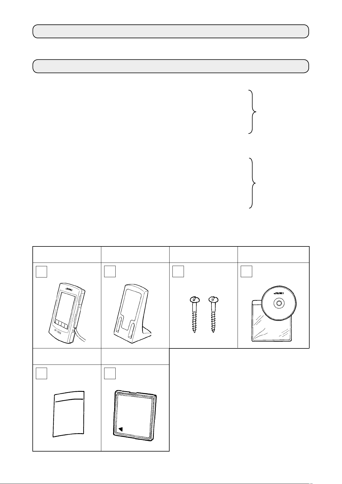
. CONTENTS OF THE ARTICLES PACKED TOGETHER
1. For those who have purchased the machine provided with IP-310 operation panel
IP-310 operation panel main unit ...........................................................1 set
1
Operation panel installing base ..............................................................1 set
2
Operation panel installing base setscrew .............................................2 pcs.
3
Set-up manual and CD-ROM (this CD-ROM) for instruction manual ....1 pc.
4
When using IP-310/IP-410 .................................................................... 1 pc.
5
5 articles above and components related to control box are packed together.
* 1
2. For those who have purchased the single unit of IP-310 operation panel
IP-310 operation panel main unit ...........................................................1 set
1
Operation panel installing base ..............................................................1 set
2
Operation panel installing base setscrew .............................................2 pcs.
3
Set-up manual and CD-ROM (this CD-ROM) for instruction manual .....1 pc.
4
When using IP-310/IP-410 ..................................................................... 1 pc.
5
Media ..................................................................................................... 1 pc.
6
* 2
6 articles above are packed together.
IP-310 operation panel
main unit
* 1, * 2
When using IP-310/IP-410 Media
* 1, * 2
Operation panel installing
base
* 1, * 2 * 1, * 2
* 2
Operation panel installing
base setscrew
Set-up manual and CD-ROM
(this CD-ROM) for instruction manual
* 1, * 2
– 1 –
Page 4
– 2 –
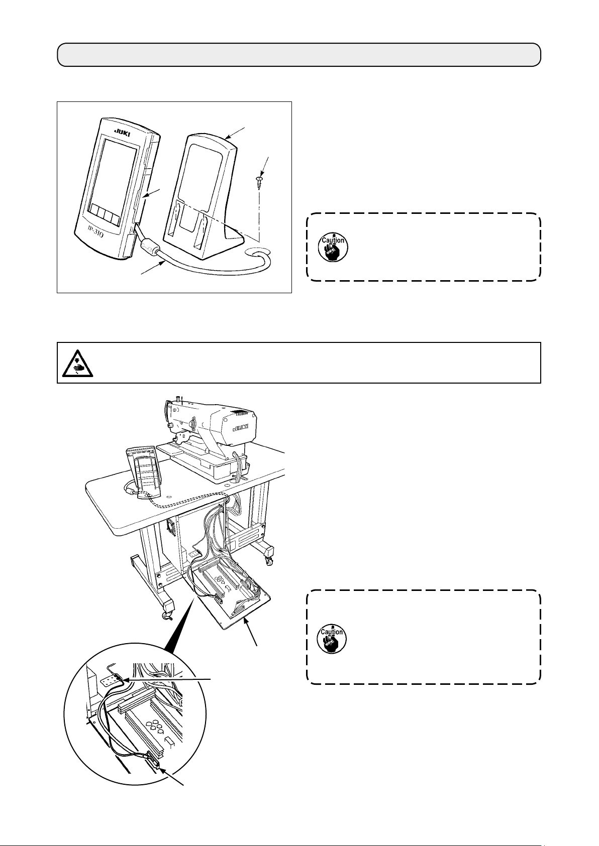
#
. INSTALLING IP-310 ON TABLE/STAN AND CONTROL BOX
1. Installing procedure of the operation panel and the installing base
1) Open cover 1 and remove cable 2 once.
3
Then connect it again to the panel on the top
surface of the table after passing it through the
4
hole in the table.
2) Fix operation panel installing plate 3 to an op-
1
2
tional place on the table with two wood screws
.
4
Install the panel at the position whe-
re X-move cover or head grip does
not interfere with it since breakage
of the panel will be caused.
2. Connecting the cord and turning ON the power
WARNING :
Turn OFF the power before starting the connecting work so as to prevent accidents caused by abrupt
start of the sewing machine.
1) Pass the cord of the operation panel through the
hole for wiring in the table and connect it with the
control box under the table. For the table without
the hole for wiring, wire the cord at the position
where there is no trouble when the machine head
is tilted or sewing is performed, and connect it
with the control box. For the connection of the
connector, connect it to CN34 of MAIN circuit
board in the control box or built in the machine
head. For the details, refer to the Instruction
Manual for the sewing machine main unit.
When the work above has been completed, turn
ON the power.
When connecting the cord, make
sure that the power of the main unit
is turned OFF. When connecting the
MAIN circuit board
Ground wire
cord in the state that the power is
turned ON, trouble or breakage of
the circuit will be caused.
CN34
Page 5
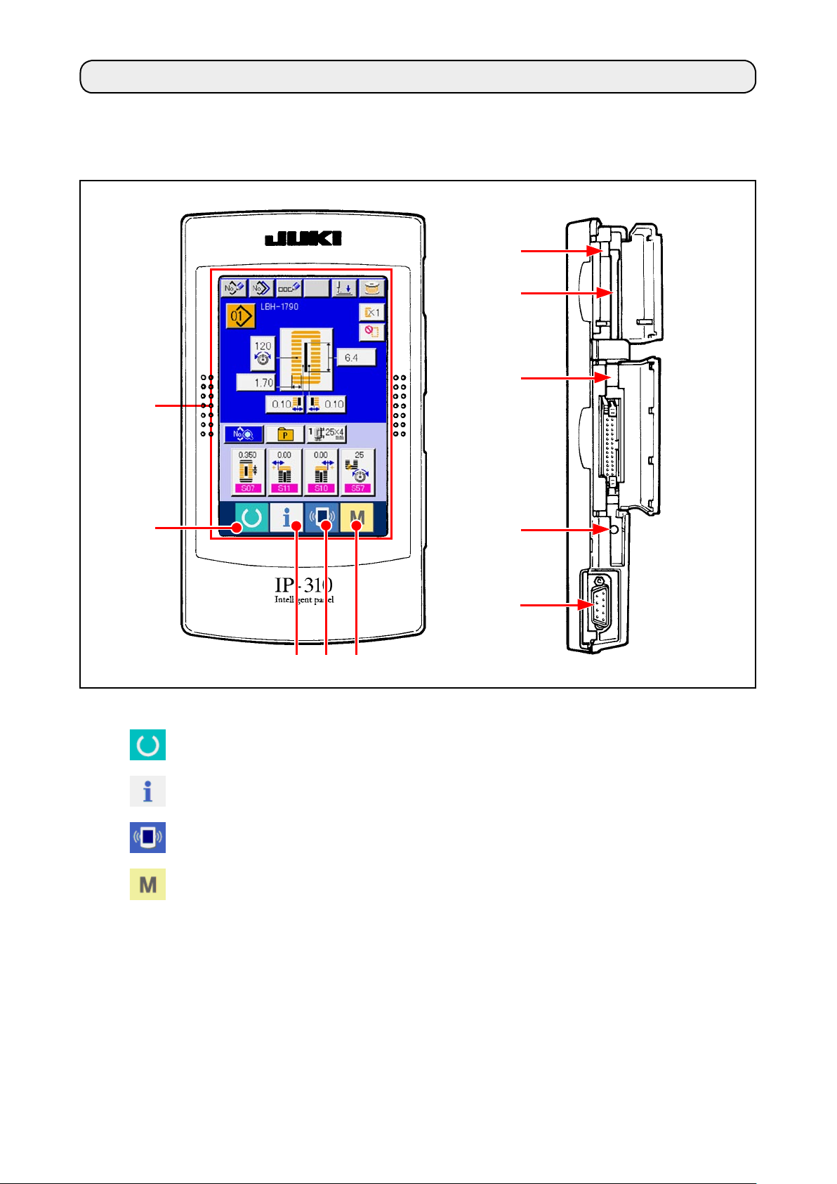
$
. EXPLANATION OF THE OPERATION PANEL
Explanation of the respective parts of the operation panel is given below.
For the details of the respective parts, refer to "1. NAME OF EACH SECTION OF THE OPERATION
PANEL" of the Instruction Manual.
1
2
(Front)
(Right side)
!0
6
9
8
4 5
3
Touch panel • LCD display section
1
2
3
4
5
MEDIA slot
6
CONNECTOR for RS-232C communication
7
VARIABLE RESISTOR for adjusting contrast
8
READY key
INFORMATION key
COMMUNICATION key
MODE key
of colored LCD screen
7
Changeover of the data input screen and the
→
sewing screen can be performed.
Changeover of the data input screen and the
→
information screen can be performed.
Changeover of the data input screen and the
→
communication screen can be performed.
Changeover of the data input screen and the
→
mode changeover screen which performs
various detail settings can be performed.
MEDIA slot (use it with lid closed.)
→
Contrast of the screen can be adjusted. Ad-
→
just it as you like.
CONNECTOR for external input
9
MEDIA take-out lever
!0
– 3 –
Page 6

– 4 –
%
.
CONNECTING PROCEDURE OF OPERATION PANEL WITH EXTERNAL VEHICLE
It is possible for this operation panel to perform communication or input of signal with the vehicles below
other than the control box.
1. Media
2. RS-232C
3. Input of signal by means of the connector for external input
Connecting procedure is given below.
1. Media
(1) Inserting direction of the media
Turn the label side of the CompactFlash (TM)
1
to this side (place the notch of the edge to
the rear. ) and insert the part that has a small
hole into the panel.
After completion of setting of the media, close
2
the cover. By closing the cover, it is possible
to access. If the media and the cover come in
contact with each other and the cover is not
closed, check the following matters.
Check that the media is securely pressed
•
Media
until it goes no further.
Check that the inserting direction of the media
•
is proper.
1. When the inserting direction is wrong, panel or media may be damaged.
2. Do not insert anything other than CompactFlash (TM).
3. IP-310 is adaptable to CompactFlash (TM) of 2GB or less.
4. IP-310 is adaptable to the format FAT16 of CompactFlash (TM). It is not adaptable to
FAT32.
5. Be sure to use the CompactFlash (TM) formatted with IP-310. For formatting procedure of CompactFlash (TM), see "%-1-(3) Performing formatting of the media", p.5.
(2) Removing procedure of the media
Hold the panel by hand, open the cover, and press the
1
media removing lever. The media is eject.
When the lever is strongly pressed, the media
may be broken by protruding and falling.
When the media is drawn out as it is, removing is com-
2
pleted.
Page 7
Cautions when using the CompactFlash (TM) :
• Do not wet it or touch it with wet hands. Fire or electric shock may be caused.
• Do not bend it or apply strong force or shock to it.
• Never perform disassembling or remodeling of it.
• Do not make the contact part of it come in contact with the metal. Data may disappear.
• Avoid storing or using it at the places below.
Place of high temperature and humidity / Place of dew condensation /
Place of much waste and dust / Place where static electricity or electrical noise is apt to occur
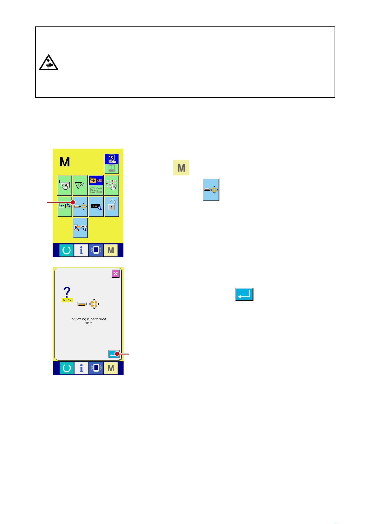
(3) Performing formatting of the media
When re-formatting the media, be sure to perform it with IP-310. The media that is formatted with the
personal computer cannot be read with IP-310.
Display the media format screen.
1
When switch is held pressed for three seconds, MEDIA
FORMAT button A is displayed on the screen. When
A
this button is pressed, the media format screen is displayed.
Start formatting of the media.
2
Set the media you desire to format to the media slot, close the
cover, press ENTER button B and formatting starts.
Save necessary data in the media to the other media before
formatting. When formating is performed, the inside data are
deleted.
B
– 5 –
Page 8
– 6 –
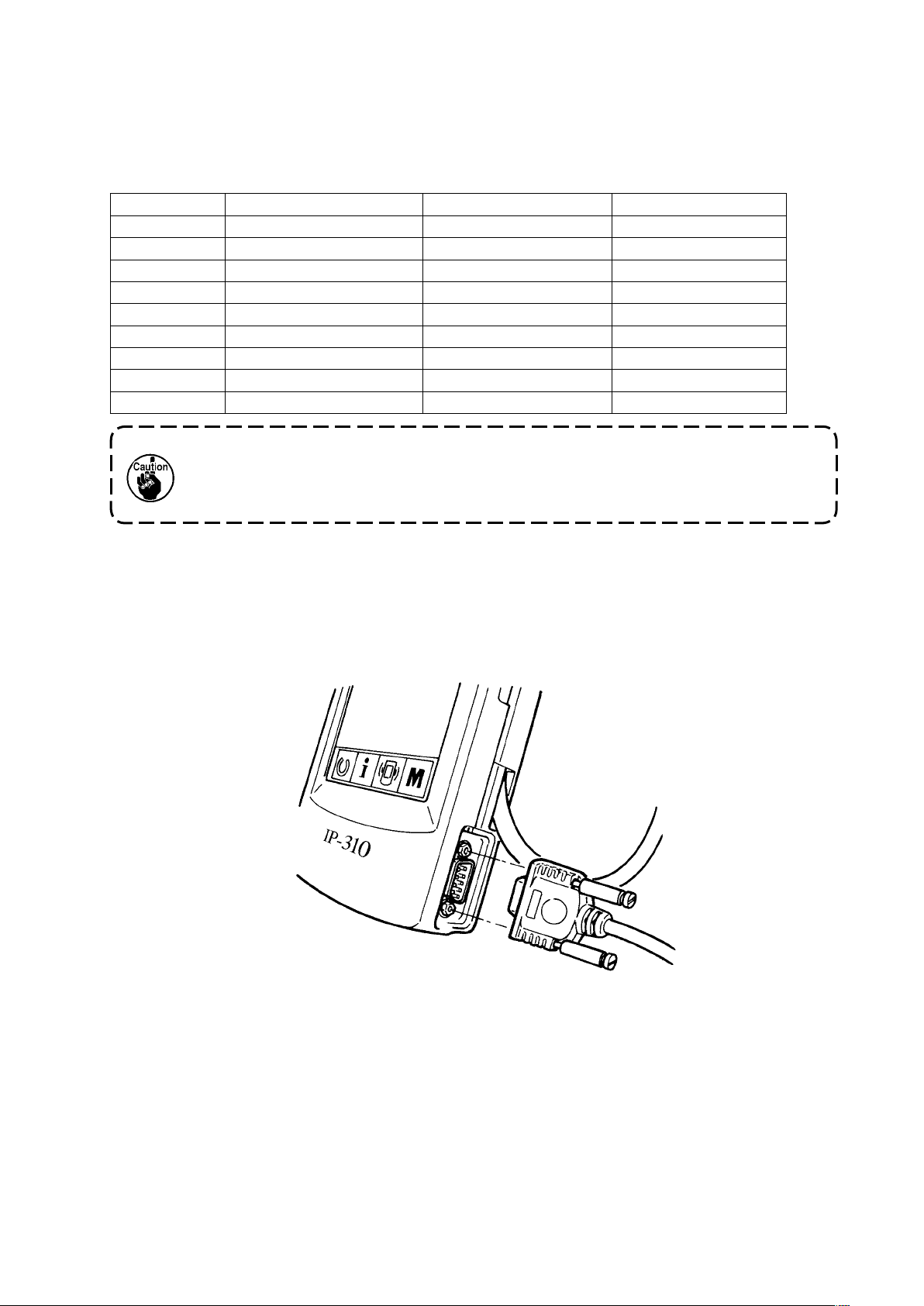
2. RS-232C
Operation panel can give and take the data with the personal computer by using communication by
means of RS-232C.
For the cable to be connected, connect the reverse type 9-pin (female) to the operation panel side. Signal
names of the operation panel are as follows.
Pin No. Signal name Function Signal direction
1 N.C. Not connected
2 RXD Receive data To panel
3 TXD Transmit data From panel
4 DTR Data terminal ready From panel
5 GND Earth
6 DSR Data set ready To panel
7 RTS Request to send From panel
8 CTS Possible to send To panel
9 N.C. Not connected
When the contact part becomes dirty, contact failure will be caused. Control so that
the contact part is not touched by hand, or that dust, oil or other foreign material does
not adhere to the contact part. Besides, be careful of handling the contact part since
the internal element is broken by the static electricity or the like.
(1) Setting procedure
1) When the lower side cover located on the side of operation panel is opened, there is a 9-pin connector
for RS-232C. Insert the cable there. When the screw for lock is attached to the connector, tighten the
screw to prevent the screw from falling.
Page 9

3. Input of signal by means of the connector for external input
It is possible to input the signal from the outside.
When the switch is connected, it is possible to use as the input of the production control information.
For the details, refer to "Observing the production control information" of the Instruction Manual.
Cable (separately-sold) as shown in the gure below
can be connected.
Relay cable A (asm.) (40008168)
1
1
3 2 1
CN105
+5V
1
SW
2
3
GND
Connector housing : KYOCERA ELCO CO. 60-8263-3038-15-000
Pin contact : KYOCERA ELCO CO. 60-8263-0513-00-808
2m
Note) The switch main unit is not installed to the
relay cable A (asm.).
When the contact part becomes dirty, contact failure will be caused. Control so that
the contact part is not touched by hand, or that dust, oil or other foreign material does
not adhere to the contact part. Besides, be careful of handling the contact part since
the internal element is broken by the static electricity or the like.
– 7 –
Page 10

– 8 –
^
. RE-SETUP OF THE PROGRAM OF THE OPERATION PANEL
When the case is as below, it is necessary to perform re-setup of the program of the operation panel.
When the operation panel is used as that for other model.
™
When version-up of the program is performed.
™
The way of performing setup of the program from the media is shown below. Besides, it is regarded that
the program to perform setup has already entered the Media.
1) First, turn ON the power. Normally, the sewing ready screen is displayed.
2) Insert the Media into the operation panel.
3) Perform operation by the procedure below.
Data edit screen
1) Press key
1
d
Communication screen 1
2) Press key
2
.
1
for three seconds.
2
3
d
Data selection screen
3) Press key
4) Press key
4
d
3
4
.
.
Page 11

5
d
Communication screen 2
5) Press key
File selection screen
6) Press key
download program at display 7 .
7) Press key
6
8
and select the
.
d
5
.
7
6
8
d
9
Communication screen 3
8) Press key
9
.
d
<-<- Start of communication ->->
d
– 9 –
Page 12

d
Screen during data deletion Screen 1 during data writing
d
Screen 2 during data writing
d
d
End screen
If the screen below is displayed, quickly
turn OFF the power and perform the
set-up again after checking [Checking
items] below.
Data writing abnormal screen
The procedure above
completes the replacing work
of application software.
Checking items
Media cover is opened during the data communication from the media.
1
Data of the media is not correct. Or, there is no data le.
2
Contact of the media is dirty. Contact is defective.
3
Do not turn OFF the power and close/open the media cover during the work.
The main unit may be broken.
– 10 –
Page 13

&
. RE-SETUP OF MAIN PROGRAM
When you have purchased the single unit of IP-310 operation panel, the media card is packed together.
You can perform re-setup of the main program of MAIN circuit board on the control box side by using this
media card.
It is necessary that the main program and panel program have to match with each other.
If not, there is a possibility that trouble such as Error "E703 or E704" occurs. Be sure to perform setup by
using the media card which is packed together.
1. When panel program matches with main program
Perform the work by the procedure below when performing version-up of the main program by using the
media card.
1) First, turn ON the power.
2) Insert the media card into the operation panel.
3) Perform operation by the procedure displayed in the screen below.
Data edit screen
1) Press key 1 for three seconds.
1
d
Communication screen 1
2) Press key 2 .
d
Data selection screen
2
3
3) Press key 3 .
4) Press key 4 .
4
d
– 11 –
Page 14

– 12 –
5
d
Communication screen 2
5) Press key 5 .
d
File selection screen
6) Press key 6 and select download
program at display 7 .
7) Press key 8 .
d
9
Communication screen 3
8) Press key 9 .
7
6
8
d
<-<- Start of communication ->->
d
Page 15

d
Screen during data writing
Screen of end of data writing
d
The procedure above completes
the replacing work of application
software.
If the screen below is displayed, quickly
turn OFF the power and perform the
set-up again after checking [Checking
items] below.
Data writing abnormal screen
Checking items
Media cover is opened during the data communication from the media.
1
Data of the media is not correct. Or, there is no data le.
2
Contact of the media is dirty. Contact is defective.
3
Do not turn OFF the power and close/open the media cover during the work.
The main unit may be broken.
– 13 –
Page 16

– 14 –
2. When panel program does not match with main program and an error occurs
Perform the work by the procedure below when replacing the main program in case trouble such as Error
"E703", "E704", etc. occurs.
1) First, turn ON the power. Error screen (E703 or E704) is displayed after turning ON the power.
2) Insert the media card into the operation panel.
3) Perform operation by the procedure displayed in the screen below.
Error screen
1) Press key 1 .
1
d
Communication screen 1
2) Press key 2 .
d
2
3
Data selection screen
3) Press key 3 .
4) Press key 4 .
4
d
Page 17

5
d
Communication screen 2
5) Press key 5 .
d
File selection screen
6) Prees key 6 and select the
download program at display 7 .
7) Press key 8 .
d
9
Communication screen 3
8) Press key 9 .
7
6
8
d
<-<- Start of communication ->->
d
– 15 –
Page 18

– 16 –
d
Screen during data writing
Screen of end of data writing
d
The procedure above
completes the replacing work
of application software.
If the screen below is displayed,
quickly turn OFF the power and
per form t he set -up aga in aft er
checking [Checking items] below.
Data writing abnormal
screen
Checking items
Media cover is opened during the data communication from the media.
1
Data of the media is not correct. Or, there is no data le.
2
Contact of the media is dirty. Contact is defective.
3
Do not turn OFF the power and close/open the media cover during the work.
The main unit may be broken.
Page 19

*
. RE-SETUP OF SERVO PROGRAM
Perform the work by the procedure below when rewriting the servo program in the same way of
SETUP OF MAIN PROGRAM"
1. When main program matches with servo program
Perform the work by the procedure below when making the servo program version-up by using the media
card.
1) First, turn ON the power. Normally, the sewing ready screen is displayed.
2) Insert the media card into the operation panel.
3) Perform operation by the procedure displayed in the screen below.
.
Data edit screen
1) Press key 1 for three seconds.
"&. RE-
3
1
d
Communication screen 1
2) Press key 2 .
d
Data selection screen
3) Press key 3 .
4) Press key 4 .
4
2
d
– 17 –
Page 20

– 18 –
5
d
Communication screen 2
5) Press key 5 .
d
File selection screen
6) Press key 6 and select the
download program at display 7 .
7) Press key 8 .
d
9
Communication screen 3
8) Press key 9 .
7
6
8
d
<-<- Start of communication ->->
d
Page 21

d
Screen during data writing
Screen of end of data writing
d
The procedure above completes
the replacing work of application
software.
If the screen below is displayed,
quickly turn OFF the power and
perform the set-up again after
checking [Checking items] below.
Data writing abnormal
screen
Checking items
Media cover is opened during the data communication from the media.
1
Data of the media is not correct. Or, there is no data le.
2
Contact of the media is dirty. Contact is defective.
3
Do not turn OFF the power and close/open the media cover during the work.
The main unit may be broken.
– 19 –
Page 22

– 20 –
2. When panel program does not match with main program and an error occurs
Perform the work by the procedure below when replacing the main program in case trouble such as Error
"E703", "E704", etc. occurs.
1) First, turn ON the power. Error screen (E703 or E704) is displayed after turning ON the power.
2) Insert the media card into the operation panel.
3) Perform operation by the procedure displayed in the screen below.
Error screen
1) Press key
1
d
Communication screen 1
2) Press key 2 .
1
.
2
3
d
Data selection screen
3) Press key 3 .
4) Press key 4 .
4
d
Page 23

5
d
Communication screen 2
5) Press key 5 .
d
File selection screen
6) Press key 6 and select the
download program at display 7 .
7) Press key 8 .
d
9
Communication screen 3
8) Press key 9 .
7
6
8
d
<-<- Start of communication ->->
d
– 21 –
Page 24

– 22 –
d
Screen during data writing
Screen of end of data writing
d
The procedure above
completes the replacing work
of application software.
If t he screen below is d isplayed ,
quickly turn O F F the pow e r a nd
pe r f o r m t h e set -u p a ga in a f te r
checking [Checking items] below.
Data writing abnormal
screen
Checking items
Media cover is opened during the data communication from the media.
1
Data of the media is not correct. Or, there is no data le.
2
Contact of the media is dirty. Contact is defective.
3
Do not turn OFF the power and close/open the media cover during the work.
The main unit may be broken.
Page 25

(
WHEN USING THE MEDIA OTHER THAN THAT PACKED TOGETHER WITH THE MACHINE
.
When copying the contents of the media card that is packed together with the machine, create the
directory structure below with the PC (personal computer) after formatting the media card to be the copy
destination with IP-310.
For the formatting procedure of the media card, see
Route
directory
Make the folder name as the model
name. However, do not put "-"
(hyphen) of the model name.
[PROG]
[LBH1790]
"%-1-(3) Performing formatting of the media", p.5
Store the program file corresponding to
the model of the aforementioned folder
name.
[APxxxxxx] (IP-310 program)
APxxxxxx.hed
APxxxxxx.p01
AMxxxxxx.i01
AMxxxxxx.i10
AMxxxxxx.i11
AMxxxxxx.i12
AMxxxxxx.i13
AMxxxxxx.i21
AMxxxxxx.i22
AMxxxxxx.i23
.
[ ] = Folder
xxxxxx = RVL code (6 digits)
MAxxxxxx.prg (Main program)
MTxxxxxx.prg (Servo program)
"CompactFlash(TM)" is the registered trademark of SanDisk Corporation, U.S.A.
– 23 –
 Loading...