

JUKI IP-200/LK-1900A Instruction Manual

ENGLISH
IP-200 / LK-1900A

CONTENTS
1. NAME OF EACH SECTION OF THE OPERATION PANEL ...............................................................4
1-1 Body.........................................................................................................................................................4
1-2 Buttons to be used in common.............................................................................................................6
2. BASIC OPERATION OF THE SEWING MACHINE.............................................................................7
3. LCD DISPLAY SECTION AT THE TIME OF SEWING SHAPE SELECTION.....................................8
3-1 Sewing shape data input screen...........................................................................................................8
3-2 Sewing screen.......................................................................................................................................11
4. PERFORMING SEWING SHAPE SELECTION.................................................................................14
5. SEWING SHAPE LIST.......................................................................................................................17
6. PERFORMING ITEM DATA CHANGE..............................................................................................19
7. CHECKING PATTERN SHAPE.........................................................................................................21
8. USING TEMPORARY STOP .............................................................................................................23
8-1 To continue performing sewing from some point in sewing...........................................................24
8-2 To perform re-sewing from the start...................................................................................................25
9. WINDING BOBBIN THREAD ............................................................................................................26
9-1 When performing winding bobbin thread while performing sewing...............................................26
9-2 When performing winding bobbin thread only..................................................................................26
10. USING COUNTER ...........................................................................................................................27
10-1 Setting procedure of the counter......................................................................................................27
10-2 Count-up releasing procedure..........................................................................................................30
10-3 How to change the counter value during sewing............................................................................31
11. PERFORMING NEW REGISTER OF USERS' PATTERN...............................................................32
12. PERFORMING NEW REGISTER OF PATTERN BUTTON.............................................................33
13. LCD DISPLAY SECTION AT THE TIME OF PATTERN BUTTON SELECTION............................35
13-1 Pattern button data input screen......................................................................................................35
13-2 Sewing screen.....................................................................................................................................38
14. PERFORMING PATTERN BUTTON NO. SELECTION...................................................................41
14-1 Selection from the data input screen ...............................................................................................41
14-2 Selection by means of the shortcut button .....................................................................................42
15. CHANGING CONTENTS OF PATTERN BUTTON..........................................................................43
16. NAMING PATTERN BUTTON.........................................................................................................45
17. COPYING PATTERN BUTTON.......................................................................................................46
18. CHANGING SEWING MODE...........................................................................................................48
19. LCD DISPLAY SECTION AT THE TIME OF COMBINATION SEWING.........................................49
1

19-1 Pattern input screen...........................................................................................................................49
19-2 Sewing screen.....................................................................................................................................51
20. PERFORMING COMBINATION SEWING.......................................................................................54
20-1 Selection of combination data ..........................................................................................................54
20-2 How to edit combination data ...........................................................................................................55
21. CHANGING MEMORY SWITCH DATA...........................................................................................57
21-1 How to change memory switch data ................................................................................................57
21-2 Memory switch data list.....................................................................................................................59
22. ERROR CODE LIST ........................................................................................................................66
23. USING COMMUNICATION FUNCTION ..........................................................................................73
23-1 Handling possible data ......................................................................................................................73
23-2 Performing communication by using the smart media..................................................................75
23-3 Performing communication by using RS-232C...............................................................................78
23-4 Take-in of the data..............................................................................................................................79
24. INFORMATION FUNCTION.............................................................................................................81
24-1 Observing the maintenance inspection information ......................................................................82
24-2 Inputting the inspection time ............................................................................................................85
24-3 Releasing procedure of the warning ................................................................................................87
24-4 Observing the production control information ...............................................................................88
24-4-1 When displaying from the information screen..........................................................................................88
24-4-2 When displaying from the sewing screen................................................................................................. 90
24-5 Performing setting of the production control information.............................................................91
24-6 Observing the working measurement information.........................................................................95
25. TRIAL SEWING FUNCTION............................................................................................................99
25-1 Performing trial sewing......................................................................................................................99
25-2 Thread tension value display color list..........................................................................................102
26. PERFORMING ADJUSTMENT OF ORIGIN OF PRESSER..........................................................103
27. PERFORMING KEY LOCK............................................................................................................104
28. DISPLAYING VERSION INFORMATION......................................................................................106
29. USING CHECK PROGRAM...........................................................................................................107
29-1 To display the check program screen............................................................................................107
29-2 Performing compensation of touch panel.....................................................................................109
29-3 Performing LCD check.....................................................................................................................112
29-4 Performing sensor check ................................................................................................................113
29-5 Number of rotations of main motor check.....................................................................................115
29-6 Performing output check.................................................................................................................116
29-7 Performing X/Y motors/origin sensors check...............................................................................117
29-8 Performing presser/thread trimmer motor/origin sensor check .................................................118
2

29-9 Performing thread clamp motor/origin sensor check...................................................................119
30. CHANGING THREAD TENSION COMMAND AT EVERY NEEDLE ENTRY POINT....................120
30-1 Adding or changing thread tension command at every needle entry point...............................120
30-2 Deleting thread tension command at every needle entry point...................................................122
31. PERFORMING RELEASE OF GREASE-UP ERROR...................................................................124
32. COMMUNICATION SCREEN OF MAINTENANCE PERSONNEL LEVEL...................................125
32-1 Data which are possible to be handled..........................................................................................125
32-2 Displaying maintenance personnel level.......................................................................................126
33. INFORMATION SCREEN OF THE MAINTENANCE PERSONNEL LEVEL.................................127
33-1 Display of error record.....................................................................................................................127
33-2 Display of the cumulative working information ............................................................................129
3
② ③ ④ ⑤
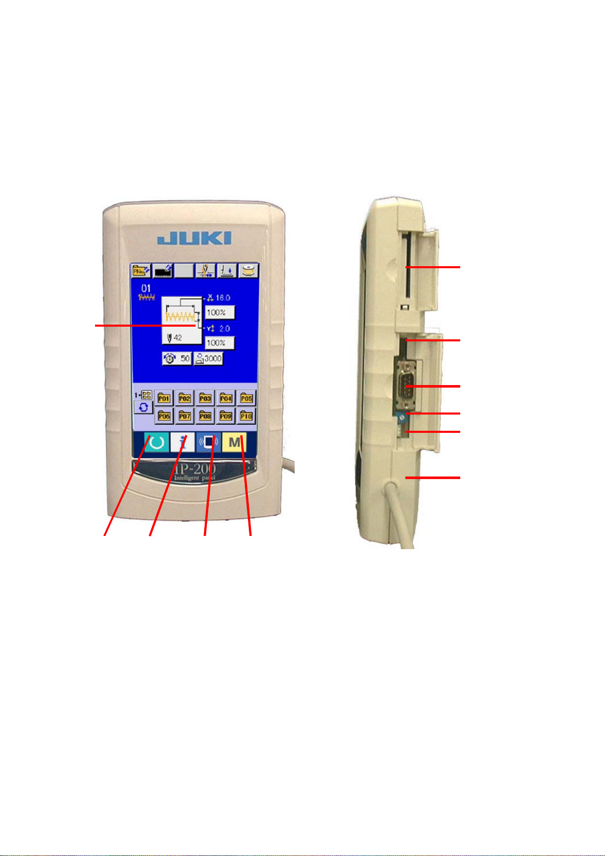
1. NAME OF EACH SECTION OF THE OPERATION PANEL
1-1 Body
(Front) (Right side)
①
⑥
⑦
⑧
⑨
⑩
⑪
4

① Touch panel・LCD display section
②
③
④
⑤
READY key →
INFORMATION key →
COMMUNICATION key →
MODE →
Changeover of the data input screen and the sewing
screen can be performed
Changeover of the data input screen and the
information screen can be performed
Changeover of the data input screen and the
communication screen can be performed.
Changeover of the data input screen and the mode
changeover screen which performs various detail
settings can be performed.
.
⑥ Smart media card slot (Close the cover for use. )
⑦ Slide switch (Not used. OFF)
⑧ Connector for RS-232C communication
⑨ Variable resistor for color LCD screen contrast adjustment
⑩ Connector for external input
⑪ Cable
5
1-2 Buttons to be used in common
The buttons which perform common operations in each screen of IP200 are as follows :
CANCEL button →
In case of the data change screen, the data being
ENTER button →
UP SCROLL button →
DOWN SCROLL button →
RESET button →
NUMERAL INPUT button →
This button closes the pop-up screen.
changed can be cancelled.
This button determines the changed data.
This button scrolls the button or the display in the upward
direction.
This button scrolls the button or the display in the
downward direction
This button performs the release of error.
This button displays ten keys and input of numerals can
be performed.
.
CHARACTER INPUT button →
→ Refer to
PRESSER DOWN button →
To raise the presser, press PRESSER UP button
BOBBIN WINDER button →
6
This button displays the character input screen.
16. NAMING PATTERN BUTTON. p.45.
This button lowers the presser and displays the presse
down screen.
displayed in the presser down screen.
This button performs bobbin thread winding.
Refer to
→
thread while performing sewing , p26.
9-1 When performing winding bobbin
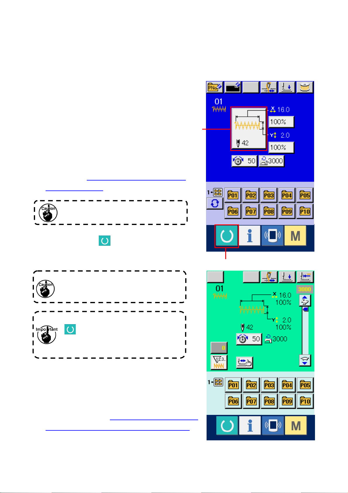
2. BASIC OPERATION OF THE SEWING MACHINE
① Turn ON the power switch
② Select the pattern No. you desire to sew.
When the power is turned ON, the data input
screen is displayed. Pattern No. button (B) which is
selected at present is displayed in the center of the
screen. Press the button to select the sewing
shape. For selecting procedure of the sewing
shape, refer to
4. PERFORMING SEWING SHAPE
SELECTION, p. 214.
Refer the pattern No. to the separate table.
When READY key
(C) is pressed, the back
color of LCD display is changed to green, and the
sewing machine is set to the sewing possible state.
When the presser is raised, be careful that
fingers are not caught in the presser since the
presser moves after having lowered.
B
C
When turning OFF the power without pressing
key, the set values of pattern No. , X/Y
scale, number of max. ro tatio n, and thread
tension are not memorized.
③ Start sewing.
Set the sewing product to the presser portion, and
operate the pedal to start the sewing machine, and
sewing starts.
* For the screen, refer to
3. LCD DISPLAY SECTION AT
THE TIME OF SEWING SHAPE SELECTION, p. 28.
7
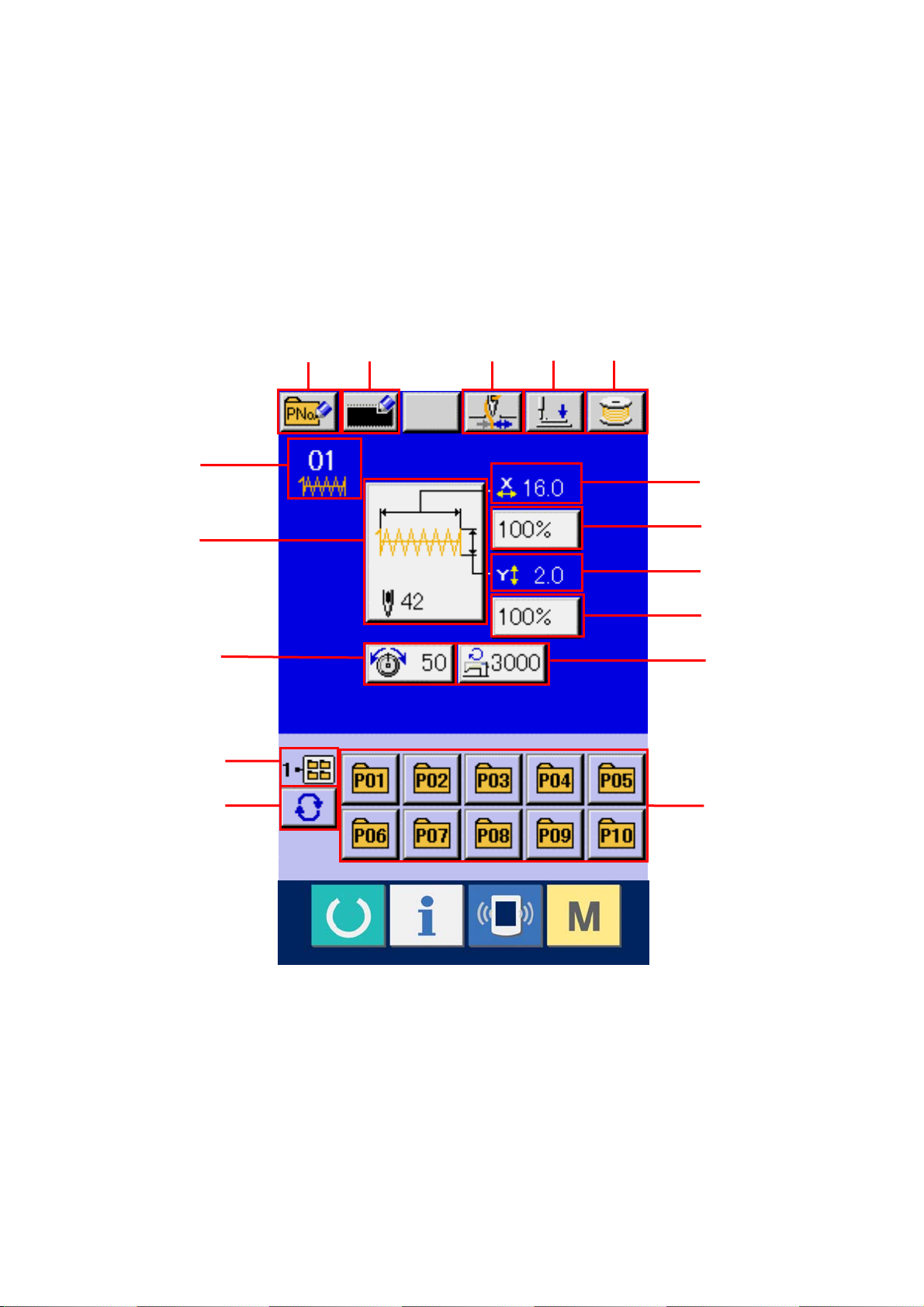
3. LCD DISPLAY SECTION AT THE TIME OF SEWING SHAPE SELECTION
3-1 Sewing shape data input screen
F
A
B
C E
D
I
J
G
K
L
H
M
N
O
P
8
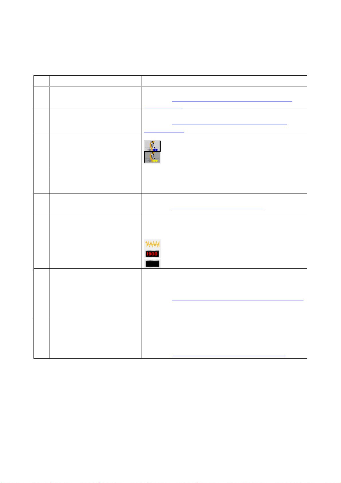
Button and display Description
PATTERN BUTTON NEW
A
REGISTER button
USERS' PATTERN NEW REGISTER
B
button
THREAD CLAMP button Effective/ineffective of thread clamp is selected.
C
PRESSER DOWN button Presser can be lowered and the presser down screen is displayed.
D
BOBBIN WINDER button Bobbin thread can be wound.
E
SEWING SHAPE NO. display
F
Pattern button new register screen is displayed.
→ Refer to 12. PERFORMING NEW REGISTER OF PATTERN
BUTTON. p. 33.
Users' pattern new register screen is displayed.
→ Refer to
PATTERN. p. 32.
To raise the presser, press the presser up button which is displayed in
the presser down screen.
→ Refer to 9. WINDING BOBBIN THREAD. p. 26.
Kind and No. of the sewing shape being selected at present are
displayed.
There are three kinds of sewing shapes below.
11. PERFORMING NEW REGISTER OF USERS'
: Thread clamp ineffective
: Thread clamp effective
: Standard pattern
: LK-1900 pattern
SEWING SHAPE SELECTION
G
button
H NEEDLE THREAD TENSION
SETTING button
: Users' pattern
Sewing shape being selected at present is displayed on this button
and when the button is pressed, the sewing shape selection screen is
displayed.
→ Refer to
Needle thread tension value which is set to the pattern data being
selected at present is displayed on this button and when the button is
pressed, the item data change screen is displayed.
→ Refer to.
4. PERFORMING SEWING SHAPE SELECTION, p. 214.
6. PERFORMING ITEM DATA CHANGE, p. 219.
9
Button and display Description
I X ACTUAL SIZE VALUE display Actual size value in X direction of sewing shape being selected at
present is displayed.
When the actual size value input is selected by setting memory switch
, X actual size value setting button is displayed.
→ Refer to
J X SCALE RATE SETTING button Scale rate in X direction of sewing shape being selected at present is
displayed on this button.
When the scale input is set to non-selection by setting memory switch
→ Refer to
K Y ACTUAL SIZE VALUE display Actual size value in Y direction of sewing shape being selected at
present is displayed.
When the actual size value input is selected by setting memory switch
→ Refer to
L Y SCALE RATE SETTING button
M MAX. SPEED LIMITATION Maximum speed limitation which is set at present is displayed on this
N FOLDER NO. display Pattern register button which is displayed indicates the folder No.
Scale rate in Y direction of sewing shape being selected at present is
displayed on this button. When the scale input is set to non-selection
by setting memory switch
scale is displayed.
→ Refer to
button and when the button is pressed, the item data change screen is
displayed.→ Refer to
which has been stored
6. PERFORMING ITEM DATA CHANGE, p. 219.
, the button goes out and the X scale is displayed.
6. PERFORMING ITEM DATA CHANGE, p. 219.
, Y actual size value setting button is displayed.
6. PERFORMING ITEM DATA CHANGE, p. 219.
, the button goes out and the Y
6. PERFORMING ITEM DATA CHANGE, p. 219.
6. PERFORMING ITEM DATA CHANGE, p. 219.
O FOLDER SELECTION button Folders to display the patterns are displayed in order.
P PATTERN REGISTER button PATTERN REGISTER buttons stored in N FOLDER NO. display are
displayed.
→ Refer to
BUTTON. p. 33
12. PERFORMING NEW REGISTER OF PATTERN
10
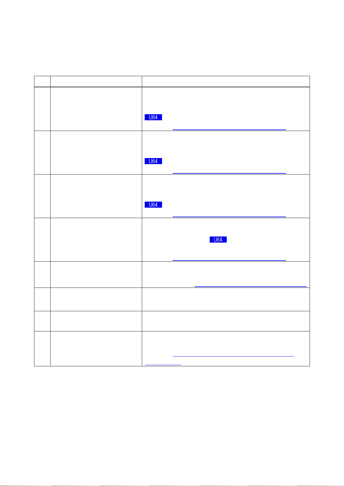
3-2 Sewing screen
E
D
A
B C
F
G
H
N
I
J
K
L
M
O
P
Q
R
11
Button and display Description
A THREAD CLAMP button Effective/ineffective of the thread clamp is selected.
: Thread clamp ineffective
: Thread clamp effective
B PRESSER DOWN button Presser can be lowered and the presser down screen is displayed.
To raise the presser, press the presser up button which is displayed in
the presser down screen.
C RETURN TO ORIGIN button This button returns the presser to the start of sewing and raises the
presser at the time of temporary stop.
D X SCALE RATE display Scale rate in X direction of sewing shape being selected is displayed.
E X ACTUAL SIZE VALUE display Actual size value in X direction of sewing shape being selected is
displayed.
F SEWING SHAPE NO. display Kind and No. of sewing shape being selected at present are
displayed.
There are three kinds of sewing shapes below.
: Standard pattern
: LK-1900 pattern
: Users' pattern
G SEWING SHAPE display Sewing shape being selected at present is displayed.
H SEWING SHAPE Total number of
stitches display
I NEEDLE THREAD TENSION
SETTING button
J COUNTER VALUE CHANGE button Existing counter value is displayed on this button. When the button is
Total number of stitches of the sewing shape being selected at
present is displayed.
* It is displayed only when the sewing shape being selected is the
standard pattern.
Needle thread tension value which is set to the pattern data being
selected at present is displayed on this button and when the button is
pressed, the item data change screen is displayed.
→ Refer to.
pressed, the counter value change screen is displayed.
→ Refer to
6. PERFORMING ITEM DATA CHANGE, p. 219.
10. USING COUNTER, p. 27.
12
Button and display Description
K COUNTER
CHANGE OVER button
L STEP SEWING botton
M FOLDER NO. display Pattern register button which is displayed indicates the folder No.
N SPEED variable resistor Number of rotations of the sewing machine can be changed.
O Y ACTUAL SIZE VALUE display Actual size value in Y direction of sewing shape being selected is
P Y SCALE RATE display Scale rate in Y direction of sewing shape being selected is displayed.
Q MAX. SPEED LIMITATION display Maximum speed limitation which is set at present is displayed.
R PATTERN REGISTER button Pattern register buttons stored in M FOLDER NO. display are
Display of sewing counter/No. of pcs. counter can be changed over.
→ Refer to 10. USING COUNTER, p. 27.
Step sewing screen is displayed. Checking of the pattern shape can
be performed.
→ Refer
which has been stored.
displayed.
displayed.
→ Refer to
BUTTON. p.33.
7. CHECKING PATTERN SHAPE, p.21.
12. PERFORMING NEW REGISTER OF PATTERN
13
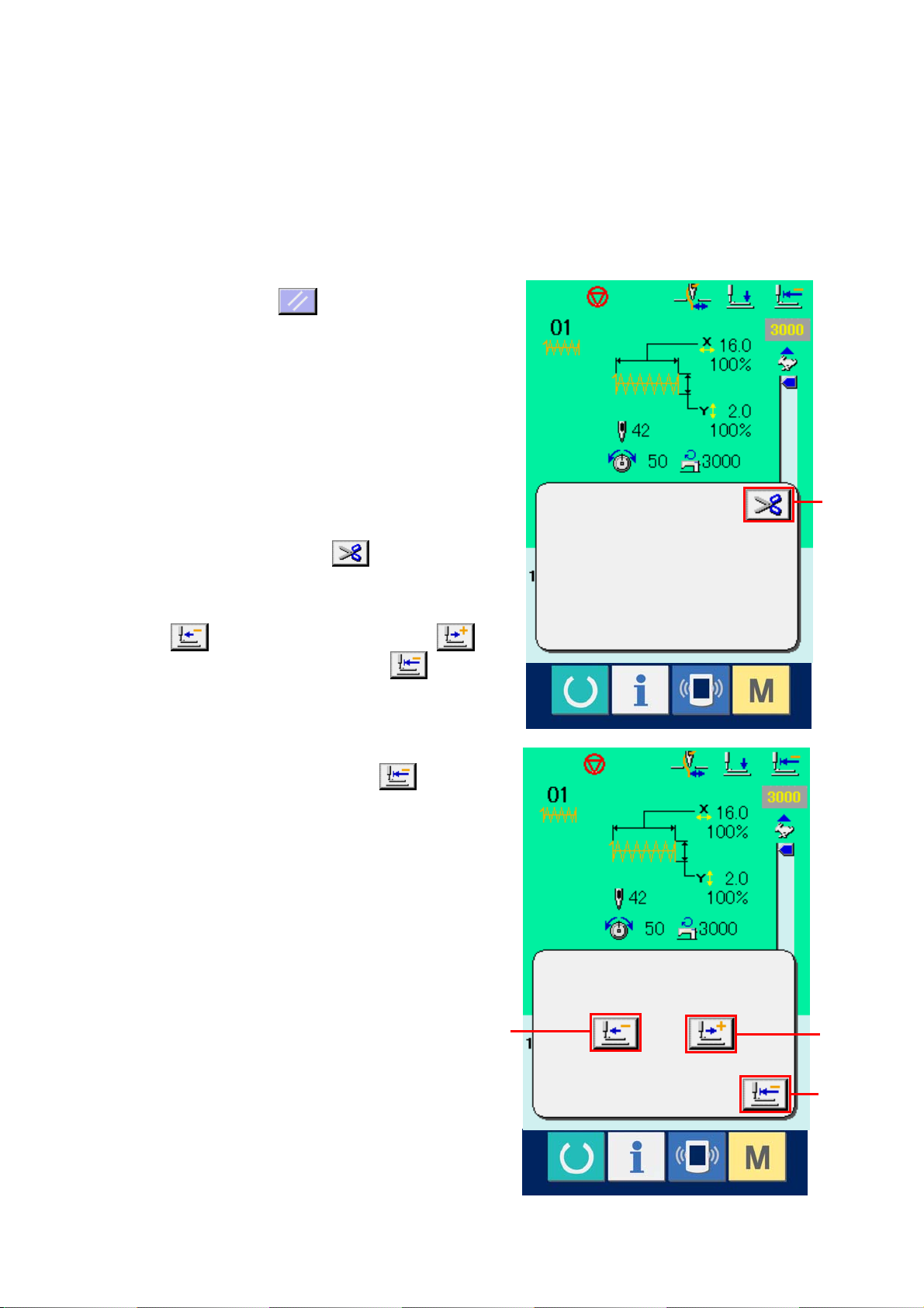
4. PERFORMING SEWING SHAPE SELECTION
① Display the data input screen.
Only in case of the data input screen (blue), the
selection of sewing shape is possible. In case of
the sewing screen (green), press READY switch
and display the data input screen (blue).
② Call the sewing shape selection screen.
Press SEWING SHAPE button
sewing shape selection screen is displayed.
③ Select the kind of sewing shape.
There are three kinds of sewing shapes in large.
Press SEWING SHAPE SELECTION button
(B).
(A) and the
A
B
14
E
④ Determine the kind of sewing shape.
There are three kinds of sewing shapes below.
Select the kind you desire from among them.
Pictograph Name
Standard pattern 64
LK-1900 pattern 99
Users' pattern 200
Maximum number
of patterns
Select the sewing shape you desire from
SEWING SHAPE SELECTION buttons (C)
and press ENTER
(D) button.
The sewing shape list screen corresponding
to the kind of sewing shape you selected is
displayed.
* For LK-1900 pattern, the SELECT button
is not displayed when ROM is not set to
C
D
MAIN p. c. b.
⑤ Select the sewing shape.
When UP or DOWN SCROLL button (E) is
pressed, the SEWING SHAPE buttons (F) are
changed over in order. Here, press the
SEWING SHAPE button you desire to select.
The details of the selected shape is displayed
at the upper part of the screen.
⑥ Determine the sewing shape.
When ENTER button
(G) is pressed,
the sewing shape is determined and the data
input screen is displayed.
G
F
15
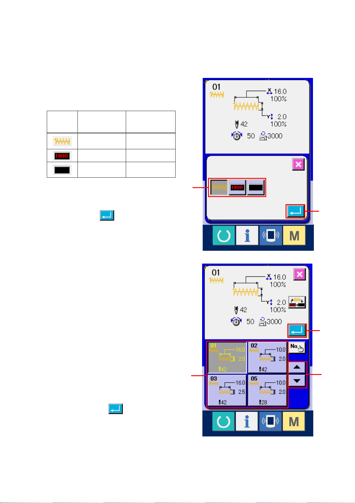
When the sewing shape is LK-1900 pattern or users'
pattern, the screen as shown on the right side is
displayed.
PATTERN NO. SELECTION buttons (H) which have
been registered to LK-1900 pattern or users' pattern
are displayed. Press the button of the pattern No. you
desire to select.
In addition, when you desire to confirm the shape you
selected, press VIEWER button
viewer screen is displayed and the selected shape is
displayed.
(I). Then the
I
H
16
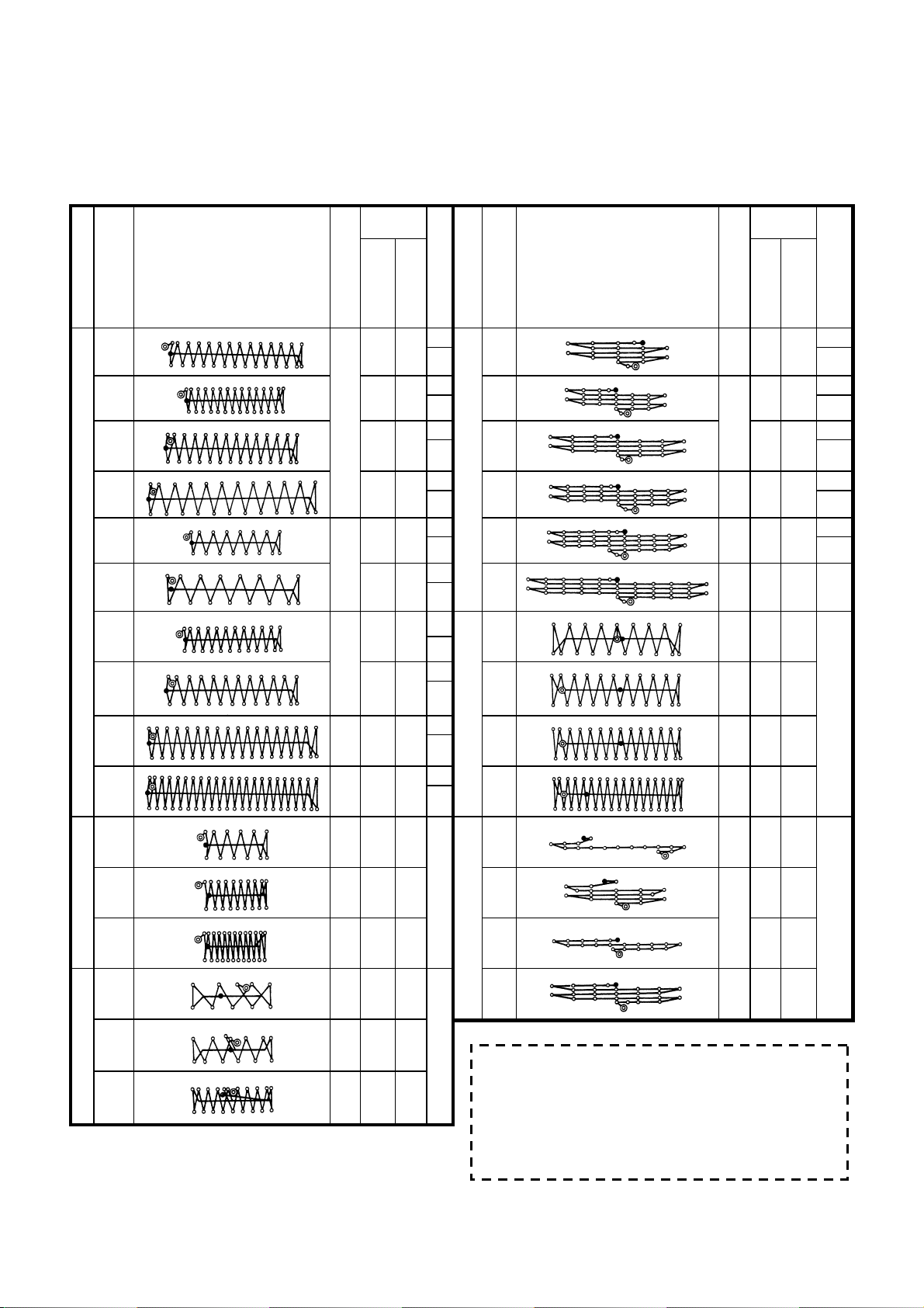
5. SEWING SHAPE LIST
Sewing
size (mm)
Sewing
size (mm)
No Stitch diagram
(51)
3
4
6
Large bar-tacking
8
9
*
10
11
12
13
Small bar-tacking
14
15
Lengthwise
Number of stitches
2.0 16
42
2.0 10
2.5 16
3.0 24
28
2.0 10
2.5 16
2.0 10
36
2.5 16
56 3.0 24
64 3.0 24
21 2.5 6 27
28 2.5 6 28
36 2.5 6
14 2.0 8
21 2.0 8
Crosswise
(Note 2) No. of presser
1 1 1
2
1 1 2
2
1 6 *
4
6 6 *
7
Linear bar-tacking
1 6 5
2
1*
4
17
2
1*
4
6*
7
Lengthwise bar-tacking
6
7
8
5
Lengthwise linear bar-tacking
No Stitch diagram
17
18
19
20
21
22
23
(Other side)
24
(Other side)
25
(Other side)
26
(Other side)
(Other side)
(Other side)
29
(Other side)
30
(Other side)
Number of stitches
(Note 2) No. of presser
Crosswise
Lengthwise
21 0 10
0 10
28
2
2
0 25
7
36 0 25
7
41 0 25
44 0 35
7
(Not
e 3)
28 20 4.0
9
(This side)
36 20 4.0
(This side)
42 20 4.0
(This side)
56 20 4.0
(This side)
18 20 0
11
(This side)
21
10 0
(This side)
20 0
(This side)
28 20 0
(This side)
(Note)
1. Sewing size shows the dimensions when the scale rate is 100%.
2. Refer the No. of presser to the separate table of presser.
3. For No. 22, process the presser blank for use.
4. Use the patterns with * marks for sewing denim.
16
Knit goods bar-tacking
28 2 0 8
5. No51 is for the machine whthout tread clamp.
17
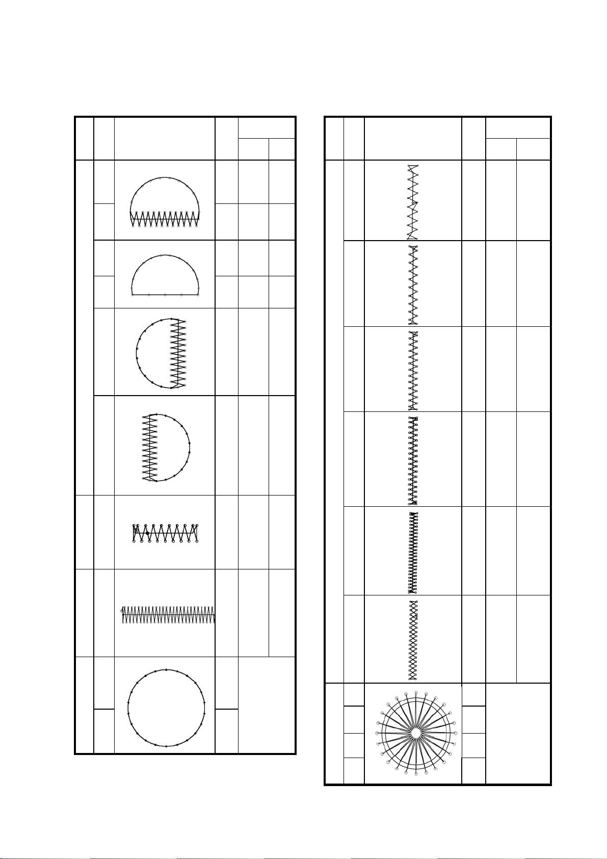
Sewing size
stitches
Lengt
(mm)
hwise
wise
Cross
No
41
No
31 52 7 10
Stitch diagram
Number of
Stitch diagram
Sewing size
(mm)
stitches
Number of
Lengt
hwise
29 20 2. 5
wise
Cross
32
33 24 6 10
34
35
Semilunar bar-tacking
36
37
63 7 12
42
31 6 12
48 10 7
43
48 10 7
44
Lengthwise bar-tacking
90 3 24
45
39 25 2. 5
45 25 2. 5
58 30 2. 5
75 30 2. 5
Large bar-tacking
38 28 2 8
Knit goods bar-tacking
39 28
40
Round bar-tacking
48
18
Φ12
46
47 91
48 99
49 148
Radial tacking
50 164
42 30 2. 5
Φ8
6. PERFORMING ITEM DATA CHANGE
① Display the data input screen.
In case of the data input screen, the change
of item data can be changed. In case of the
sewing screen (green), press READY switch
to display the data input screen (blue).
* Thread tension value can be changed even in
the sewing screen.
② Display the item data input screen.
When the button of the item data you desire to
change is pressed, the item data input screen
is displayed.
There are four items of the item data below.
Item Input range Initial value
A Scale rate in X direction 20 to 200 (%) 100(%)
A
B
C D
B Scale rate in Y direction 20 to 200 (%) 100(%)
C Thread tension 0 to 200 50
D Max. speed limitation 400 to 3,000 (rpm) 3,000 (rpm)
* A Scale rate in X direction and B Scale rate in Y direction can be changed to actual size value input
by selection of the memory switch
.
The setting exceeding 100% is dangerous since needle and the cloth presser interferes
with each other and needle breakage or the like will occur.
19
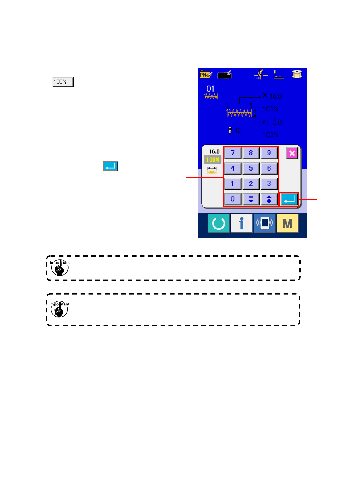
For example, input X scale rate.
Press
(A) to display the item data input
screen.
③ Input the data.
Input the value you desire with ten keys and
+/- keys (E).
④ Determine the data.
When ENTER button
the data is determined.
(F) is pressed,
E
* For the other item data, the data can be
changed by the same operation.
F
When turning OFF the power without pressing RE ADY key, the set values of pattern
No. , X/Y scale, number of max. rotation, and thread tension are not memorized.
In case thread tension is changed in the read state, the set value w hen the power is
turned OFF without pressing READY key or without performing sewing is not stored in
memory.
20
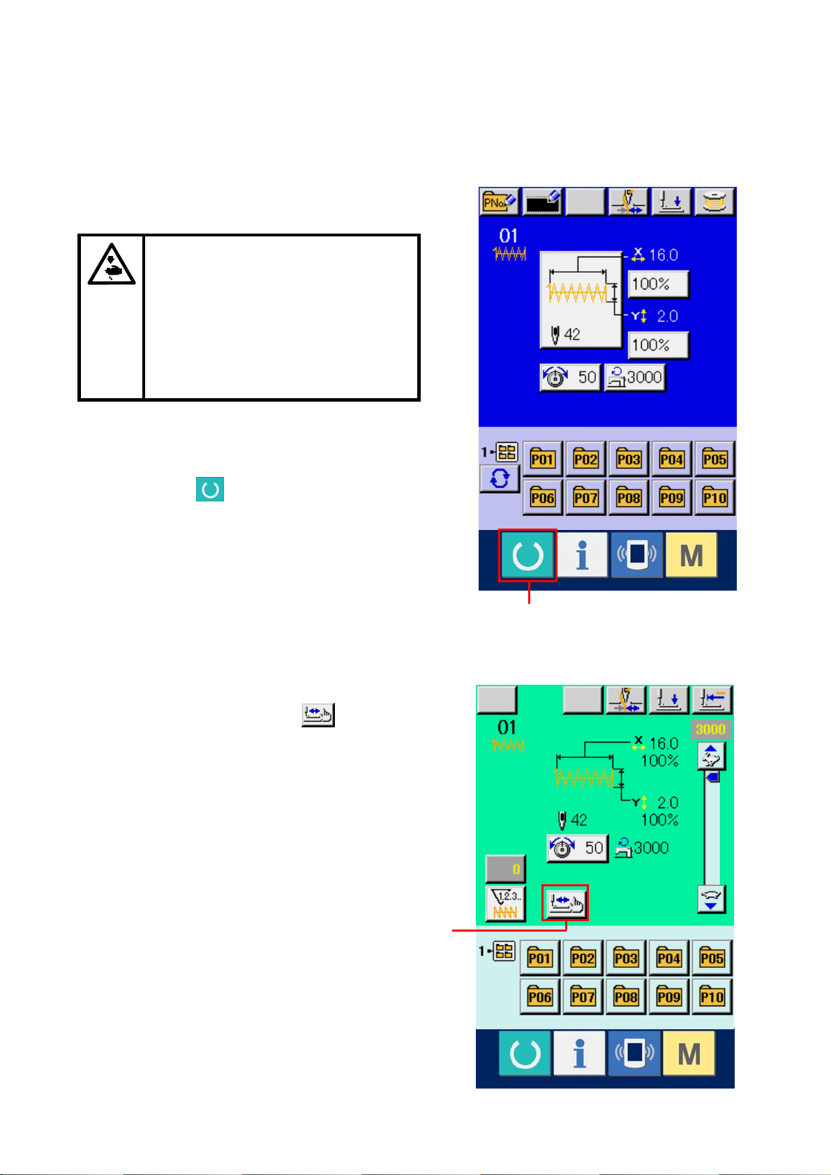
7. CHECKING PATTERN SHAPE
Make sure without fail of the contour
of the sewing pattern after selection
of the sewing pattern. If the sewing
pattern extends outside the work
clamp feet, the needle will interfere
with the work clamp feet during
sewing, causing dangerous troubles
including needle breakage.
① Display the sewing screen.
Display the data input screen (blue) and press
READY key
LCD changes to green and sewing is possible.
② Display the step sewing screen.
When STEP SEWING button
pressed, the step sewing screen is displayed.
(C). Then the back-light of
(B) is
A
21
B
③ Lower the presser with the foot switch.
The work clamp feet do not go up even
when the foot sw itch is detached.
④ Proceed stitching wi th the presser lowered.
Check the shape with PRESSER BACK button
(C) and PRESSER FORWARD button
(D).
⑤ Finish checking the shape.
When CANCEL button
(E) is pressed, the
screen returns to the sewing screen. When the
checking of the shape is not in the position of
the start of sewing or that of the end of sewing,
press the foot switch. Then it is possible to
C
E
D
sew from the midway of checking.
The presser does not come down
immediately after turning ON the power.
22
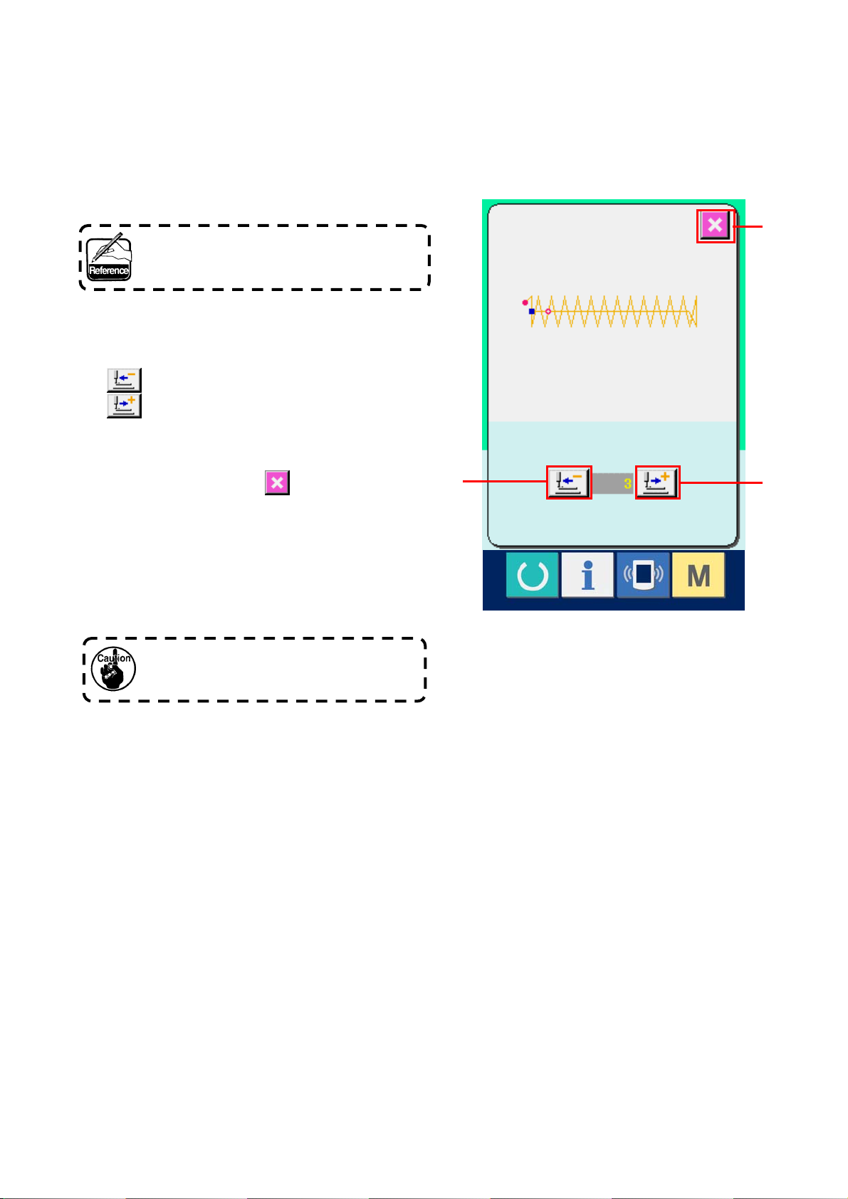
8. USING TEMPORARY STOP
When the panel temporary stop button is selected with
memory switch
(A) is displayed on the sewing screen. When the
temporary stop switch is pressed during sewing, the
sewing machine can be stopped. At this time, the error
screen is displayed to inform that the stop switch is
pressed.
Perform the same operation when the external
switch is used for the temporary stop.
, TEMPORARY STOP button
A
B
23
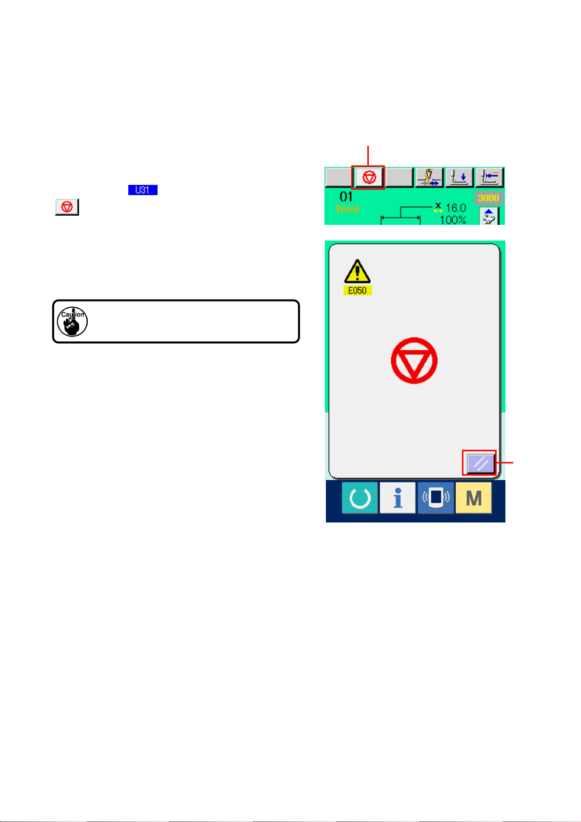
8-1 To continue performing sewing from some point in sewing
① Release the error.
Press RESET button
(B) to release the
error and the sewing screen is displayed.
② Perform thread trimming.
Press THREAD TRIM button
perform When thread trimming has been
performed, FEED BACK button
(D) ,FEED FORWARD button
RETERN TO ORIGIN button
displayed on the screen.
(C) to
C
(E) and
(F) are
③ Adjust the presser to the re-sewing pssition.
When FEED BACK button
(D) is pressed,
the peresser returnds stich and by stitch and
when FEED FORWARD button
(E) is
pressed, it advances stich by sitich. Move the
presser to the re-sewing position.
④ Re-start the sewing
When the pedal is depressed, sewing starts
again.
D
E
F
24
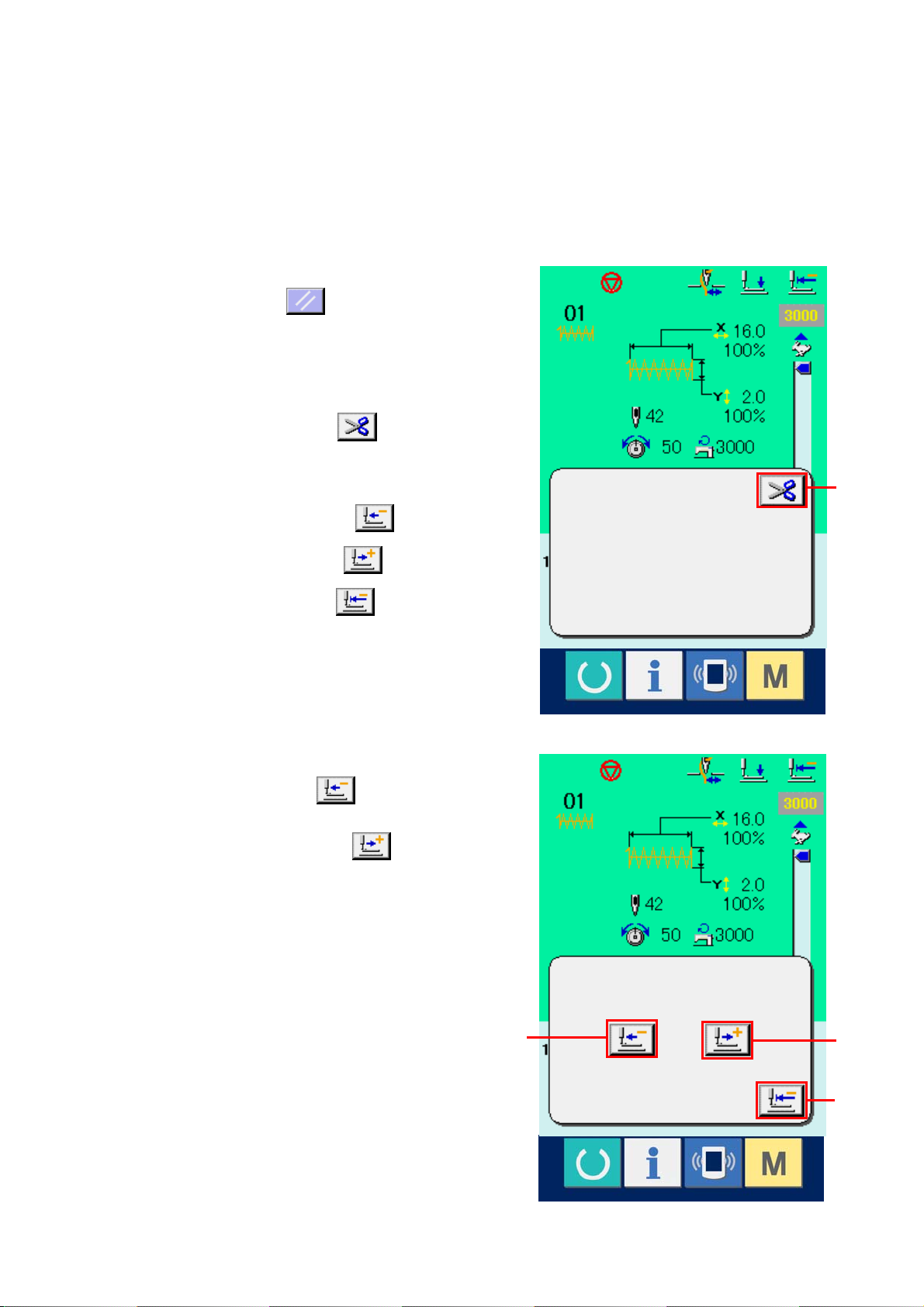
8-2 To perform re-sewing from the start
① Release the error.
Press RESET button
error and the sewing screen is displayed.
② Perform thread trimming.
Press THREAD TRIM button
thread trimming.
When thread trimming is performed, FEED BACK
button
(E) and RETURN TO ORIGIN button
are displayed on the screen.
③ Return to the origin.
(D), FEED FORWARD button
(B) to release the
(C) to perform
C
(F)
When RETURN TO ORIGIN button
pressed, the pop-up is closed, the sewing
screen is displayed and the machine returns to
the position of the start of sewing.
④ Perform again the sewing work from the
start
When the pedal is depressed, sewing starts
again.
25
(F) is
D
E
F
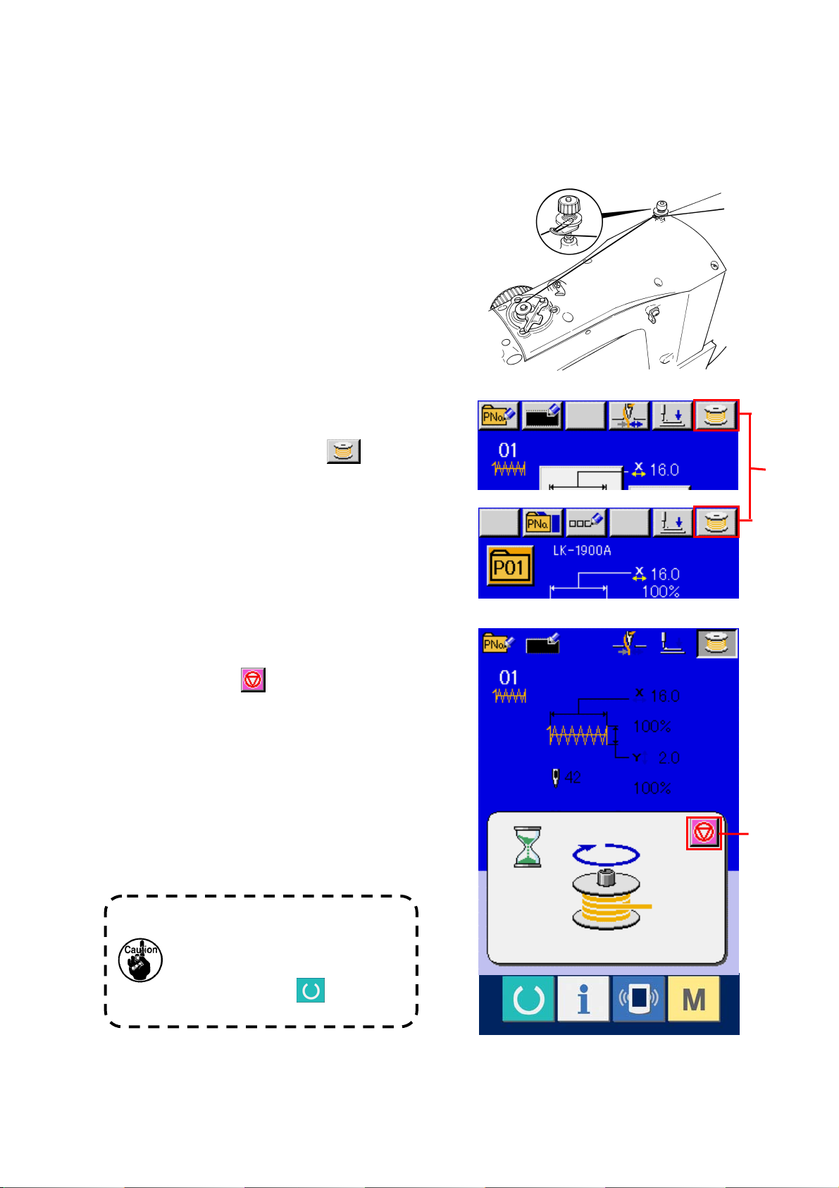
9. WINDING BOBBIN THREAD
9-1 When performing winding bobbin thread
while performing sewing
Pass the thread to wind bobbin thread as shown in
the figure on the right side.
9-2 When performing winding bobbin thread only
① Display the bobbin winding screen.
Press BOBBIN WINDER button
(A) in the
data input screen (blue) and the bobbin winding
screen is displayed.
② Start bobbin wi nding.
Depress the start pedal, and the sewing machine
rotates and starts winding bobbin thread.
③ Stop the sewing machine.
Press STOP button
(B) and the sewing
machine stops and returns to the normal mode.
Or, depress the start pedal again during winding
bobbin and the sewing machine stops while the
bobbin thread winding mode stays as it is.
Depress the start pedal again and the bobbin
winding starts again. Use this way when winding
bobbin thread around plural bobbins.
A
B
Bobbin winder does not work
immediately after turning ON the
power. Perform the bobbin winding
after setting pattern No. or the like
once, pressing the
making the sewing LED light up.
key, and
26
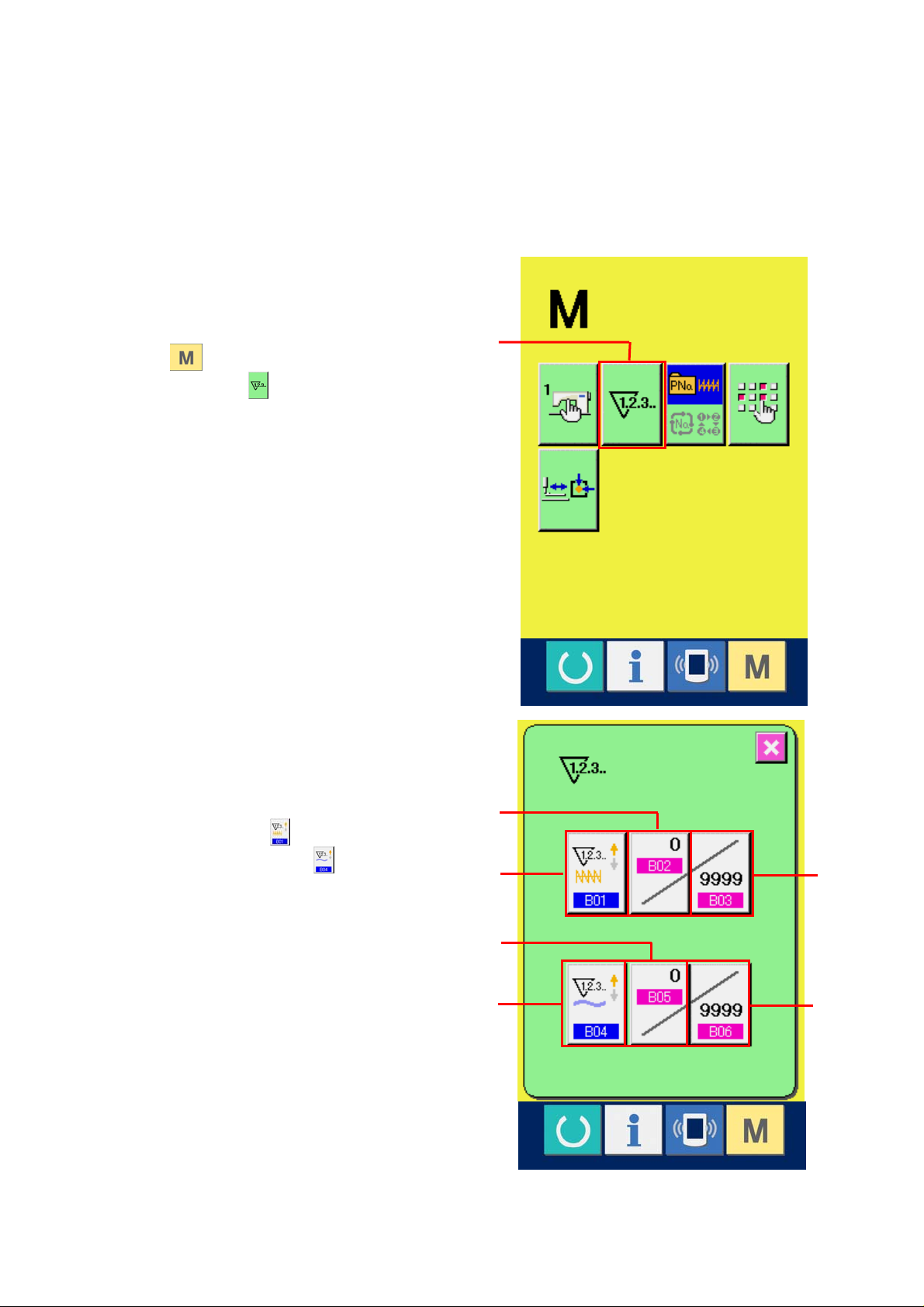
10. USING COUNTER
10-1 Setting procedure of the counter
① Display the counter setting screen.
Press
SETTING button
screen. When this button is pressed, the
counter setting screen is displayed.
② Selection of kinds of counters
This sewing machine has two kinds of
counters, i. e. , sewing counter and No. of pcs.
switch and the COUNTER
(A) is displayed on the
A
counter. Press SEWING COUNTER KIND
SELECTION button
KIND SELECTION button
the counter kind selection screen. The kinds
of the respective counters can be set
separately.
27
(B) or NO. OF PCS.
(C) to display
E
C
D
B
F
G
[ Sewing counter ]
UP counter
:
Every time the sewing of one shape is performed,
the existing value is counted up. When the existing
value is equal to the set value, the count-up screen
is displayed.
DOWN counter
:
Every time the sewing of one shape is performed,
the existing value is counted down.
When the existing value is reached to "0", the
count-up screen is displayed.
Counter not used
[ No. of pcs. Counter ]
UP counter
:
Every time one combination sewing is performed,
the existing value is counted up. When the existing
value is equal to the set value, the count-up screen
is displayed.
DOWN counter
:
Every time one combination sewing is performed,
the existing value is counted down. When the
existing value is reached to "0", the count-up
screen is displayed.
Counter not used
28
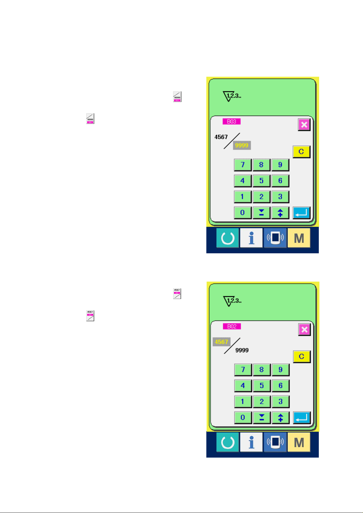
③ Change of counter set value
In case of the sewing counter, press button
(F) and in case of the No. of pcs. counter,
press button
screen is displayed.
Here, input the set value.
When "0" is inputted in the set value, the
display of count-up screen is not performed.
(G) and the set value input
④ Change of counter existing value
In case of the sewing counter, press button
(D) and in case of the No. of pcs. counter,
press button
input screen is displayed.
Here, input the existing value.
(E) and the existing value
29
 Loading...