

Page 1

ENGLISH
IP-110 TYPE F
INSTRUCTION MANUAL
* "CompactFlash(TM)" is the registered trademark of SanDisk Corporation, U.S.A.
i
No.00
40
Page 2
CONTENTS
1. INSTALLING THE OPERATION PANEL .......................................................................1
2. CONNECTING THE CORD ...........................................................................................1
3. MACHINE HEAD SETTINGS ........................................................................................2
4. ADJUSTING THE MACHINE HEAD ANGLE
(DIRECT-DRIVE MOTOR TYPE SEWING MACHINE ONLY) .......................................3
5. EXPLANATION OF THE OPERATION PANEL.............................................................4
5-1. Names and functions of each components .................................................................................4
5-2. Adjusting the contrast of the operation panel screen ................................................................6
5-3. Connection of the production support switch ............................................................................6
5-4. Basic screen ...................................................................................................................................7
5-5. How to operate the operation panel for sewing stitching patterns ...........................................9
(1) Reverse stitching pattern ...................................................................................................................9
(2) Overlapped stitching pattern ...........................................................................................................11
(3) Programmed stitching pattern
(4) Cycle sewing pattern ........................................................................................................................16
.........................................................................................................12
6. BOBBIN COUNTER ....................................................................................................18
7. NO. OF PCS. COUNTER .............................................................................................19
8. RE-SEWING SWITCH .................................................................................................19
9. NEEDLE UP/DOWN COMPENSATION SWITCH .......................................................20
10. ON/OFF SWITCH OF THE MATERIAL EDGE SENSOR ......................................20
11. AUTOMATIC THREAD TRIMMING SWITCH ........................................................20
12. ONE-SHOT AUTOMATIC STITCHING SWITCH ...................................................20
13. THREAD TRIMMING PROHIBITION SWITCH ......................................................21
14. SIMPLIFIED FUNCTION SETTING .............................................................................22
15. KEY-LOCK FUNCTION SETTING ..............................................................................23
16. FUNCTION SETTING ..................................................................................................24
17. OPTIONAL INPUT/OUTPUT SETTINGS ....................................................................29
18. AUTOMATIC COMPENSATION OF NEUTRAL POINT OF THE PEDAL SENSOR ....30
19. INITIALIZATION OF THE SETTING DATA .................................................................31
20. INFORMATION ............................................................................................................32
(1) Maintenance management function ................................................................................................32
(2) Working measurement function ......................................................................................................36
21. EXTERNAL INTERFACE ............................................................................................38
22. ERROR DISPLAY ........................................................................................................38
22-1. Error code list (Error display in panel).....................................................................................39
i
Page 3

WARNING :
This Instruction Manual describes the operation panel IP-110F.
Be sure to use this operation panel after having read to fully understand the "Safety precautions" in
the Instruction Manual for the SC-920 (control box).
In addition, be careful not to splash water or oil on it, or shock such as dropping and the like since
this product is a precision instrument.
1. INSTALLING THE OPERATION PANEL
WARNING :
To prevent personal injury caused by abrupt start of the sewing machine, carry out the work after
turning OFF the power switch and ascertaining that the motor has completely stopped.
2
4
1
6
3
5
1) Remove side plate setscrews 1 from the side plate.
2) Install operation panelInstall operation panel 2 on the machine head using screws 5, plain washer 3, toothed washer 6 and
rubber seat 4 supplied with the panel.
1. DDL-9000B (Not provided with AK) is given as an example of installing procedure.
2. Screw to install the panel changes according to the machine head used. Refer to Table 1 and con-
rm the kind of screw.
< The relation between the respective machine heads and the positions of installing hole of the bracket are as described in the table. >
Table 1
1
2 3
4
5 6
DDL-9000A
DDL-9000B
DLN-9010
LH-3500A
Installing hole
-
1
5
-
1
5
-
2
5
-
2
5
M5 X 12
M5 X 16
3/16-28 L=14
M5 X 14 Side plate setscrew
Screw
Screw supplied with panel
as accessories
Screw supplied with panel
as accessories
Screw supplied with panel
as accessories
2. CONNECTING THE CORD
1
A
1) Route cord 1 of the operation panel through
hole A in the table toward the underside of the
table.
2) Refer to the Instruction Manual for the SC-920
for how to connect the connector.
- 1 -
Page 4
3. MACHINE HEAD SETTINGS
[Function settings list screen]
2 1
[Sewing common data screen]
3
[Machine head type display screen]
1) Keeping switch 1 held pressed, turn the power
ON. Then the screen is changed over to the
function settings list screen.
When you press switch 2, the screen is
changed over to the sewing common data
screen.
2) When you press switch 3, the screen is
changed over to the machine head type display
screen.
3) The displayed machine head type is the machine
head you have selected. When you press switch
, the screen is changed over to the machine
4
head type setting popup screen.
4
[Machine head type setting popup screen]
5
6 7
4) You may selected the machine head as desired
by pressing switches 5 and
* Refer to the separate sheet of "Sewing machine
setup precaution" or the "Machine head list"
given on the separate sheet for the machine
head types.
5) Once you have determined the machine head
type, press switch 7. The screen is changed
over to the “machine head type display screen"
to display the machine head type you have
selected. Turn the power switch OFF to exit from
the machine head setting.
6
.
- 2 -
Page 5
4. ADJUSTING THE MACHINE HEAD ANGLEADJUSTING THE MACHINE HEAD ANGLE (DIRECT-DRIVE MOTOR TYPE SEWING MACHINE ONLY)
WARNING :
Be sure to perform the angle adjustment of the machine head by the operation below before using
the machine head.
[Machine head angle adjusting screen]
3
1
1) Keeping switch 1 held pressed, turn the power
ON. Then the screen is changed over to the
machine head angle adjusting screen.
2) Turn the machine head pulley by hand until the
main shaft reference signal is detected. Then,
the angle transmitted by the main shaft reference
signal is displayed in reverse video. (The value
shown in the gure is a value for reference.)
3) In this state, align the white dot 2 of the hand-
wheel with the concave 3 of the handwheel
cover as shown in the gure.
2
4
4) Once the angle is determined, press switch 4.
The angle displayed in reverse video is now dis-
played in normal video and the angle is replaced
by the adjusted one. Turn the power switch OFF
to exit from the angle adjustment.
- 3 -
Page 6
5. EXPLANATION OF THE OPERATION PANEL
5-1. Names and functions of each components
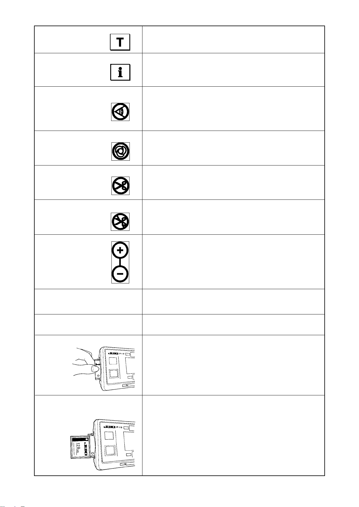
9
!8
!7
!6
1
3 4
!0
!5
6
!3
7
2
Re-sewing switch
1
Needle up/down compensating switch
2
Screen changeover switch
3
With/without reverse feed stitch at sewing start switch
4
With/without reverse feed stitch at sewing end switch
5
Reset switch
6
Teaching switch
7
Re-sewing switch
1
Needle up/down
2
5
compensating switch
Screen changeover
3
switch
!4
Information switch
8
Material edge sensor switch
9
One-shot automatic sewing switch
!0
With/without automatic thread trimmer switch
!1
Thread trimming prohibiting switch
!2
Counter value setting switch
!3
Max.speed limitation variable resistor
!4
!1
!2
8
Power display lamp
!5
Media cover
!6
Media slot
!7
(Media inserting opening)
CompactFlash(TM)
!8
(Optional : Part No.40091100)
This switch is used to continue sewing from the step on the way
after replacing bobbin thread when bobbin thread has run out
during program stitching step.
This is the switch to perform needle up/down compensating stitching.
(Needle up/down compensating stitching and one stitch compensating
stitching can be changed over with function setting No. 22.)
This is the switch to change over the screen.
With/without reverse feed stitch
4
at sewing start switch
With/without reverse feed stitch
5
at sewing end switch
Reset switch
6
This is the switch to turn ON/OFF automatic reverse feed stitch
at sewing start.
* This switch cannot be used with the sewing machine which is
not provided with automatic reverse feed stitching device.
This is the switch to turn ON/OFF automatic reverse feed stitch
at sewing end.
* This switch cannot be used with the sewing machine which is
not provided with automatic reverse feed stitching device.
This is the switch to make the value of bobbin thread counter or
sewing counter the set value.
- 4 -
Page 7
Teaching switch
7
This is the switch to set the setting of the number of stitches with
the value of number of stitches which has been actually sewn.
Information switch
8
Material edge sensor switch
9
One-shot automatic
!0
sewing switch
With/without automatic
!1
thread trimmer switch
Thread trimming
!2
prohibiting switch
This is the switch to perform various function settings.
Rendered effective when the material edge sensor is installed on
the machine.
Used for selecting whether or not the material edge sensor is
used during sewing.
When this switch is set to effective at the time of program
stitching, the sewing machine automatically operates up to the
specied number of stitches.
When this switch is set to effective at the time of using the
material end sensor for the reverse feed stitching pattern, the
thread trimmer automatically trims the thread upon completion of
sewing the specied number of stitches.
This switch prohibits all thread trimmings.
* This switch cannot be used with the sewing machine which is
not provided with the automatic thread trimming device.
Counter value setting
!3
switch
Max. speed limitation variable
!4
resistor
Power display lamp
!5
Media slot cover
!6
Media slot
!7
(Media inserting opening)
This is the switch to set the value of bobbin thread counter or No.
of pcs. counter.
When moving the resistor in the left direction, max. speed is limited.
This lamp lights up when the power switch is turned ON.
This is the cover for media inserting opening.
To open the cover, place your nger on the notch located on the
side of the cover as shown in the gure and push the cover in the
direction of left slanting rear.
* There are some functions that are not able to be operated
with the cover opened. Do not close the cover unless the
CompactFlash(TM) is completely inserted.
To set CompactFlash(TM), place the label face of the
CompactFlash(TM) to the front and insert the part that has a
small hole (place the notch of the edge to the rear) to the panel.
To remove the CompactFlash(TM), hold it between your ngers
and draw it out.
* When the inserting direction of the CompactFlash(TM) is wrong,
the panel and the CompactFlash(TM) may be damaged. Do not
insert anything other than the CompactFlash(TM).
- 5 -
Page 8
5-2. Adjusting the contrast of the operation panel screen
1) Press in the direction of arrow mark the click of
of cord outlet cover
A
breakage, do not touch the circuit board
pattern and the connector terminal.
el to prevent it from breakage.
2
A
Light
Shade
3
section
the rear of operation panel 1 and remove the
cover.
2) Turn LCD screen display brightness adjustment
variable resistor 3 to adjust the brightness (con-
trast) of LCD screen.
1. To prevent the operation panel from
1
2. Do not disassemble the operation pan-
assembled in
2
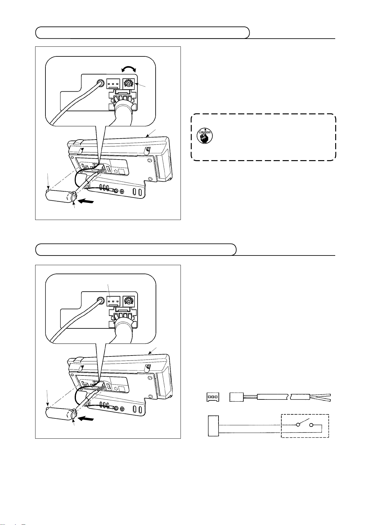
5-3. Connection of the production support switch
1) Press in the direction of arrow mark the click of
3
1
2
A
section
the rear of operation panel 1 and remove the
cover.
2) Connect the optional junction cable connector to
connector CN105 3 of the production support
switch.
Note) Pr e pare the switch ma i n u n i t by t h e
Optional relay cable A (asm.)
JUKI Part No. 40008168
3 2 1
CN105
+ 5V
SW
GND
of cord outlet cover
A
assembled in
2
customers or ask JUKI business office
about it.
1
2
3
- 6 -
Page 9
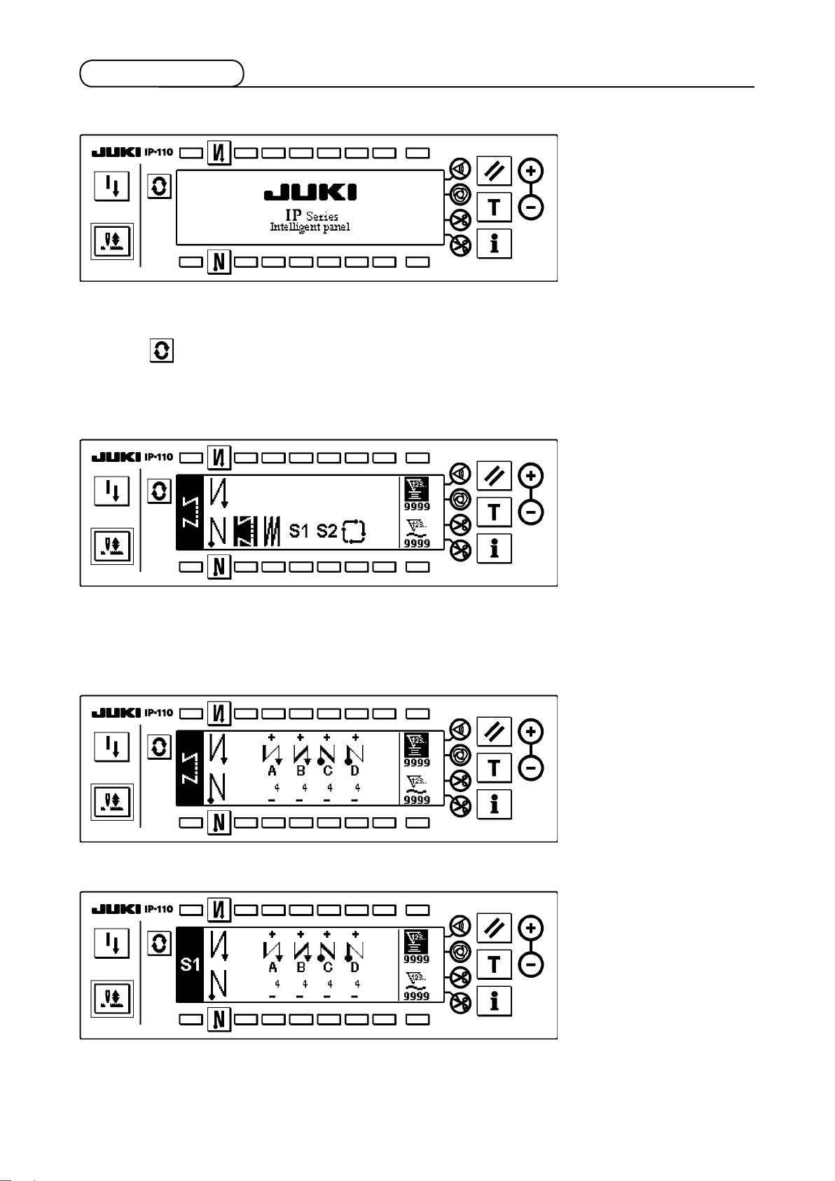
5-4. Basic screen
WELCOME screen is displayed immediately after turning ON the power.
The screen immediately after WELCOME screen becomes the screen that performs the sewing pattern
setting that was selected when turning OFF the power previously.
Every time switch is pressed, the screen changes.
Pattern list screen
■
Selection of the respective shapes is performed.
Number of stitches of back tuck stitching setting screen
■
Setting of number of stitches of reverse stitching is performed.
When reverse stitching pattern is selected
<
When programmed stitching pattern 1 is selected
<
>
>
- 7 -
Page 10
Number of stitches of overlapped stitching setting screen
■
Setting of number of stitches of overlapped stitching is performed.
Programmed stitching setting screen
■
Setting of the respective conditions of programmed stitching is performed.
When programmed stitching pattern 1 is selected
<
>
Cycle sewing setting screen
■
Setting of the step of cycle sewing is performed.
Cycle sewing pattern setting pop-up
■
Setting of the pattern of cycle sewing is performed.
- 8 -
Page 11
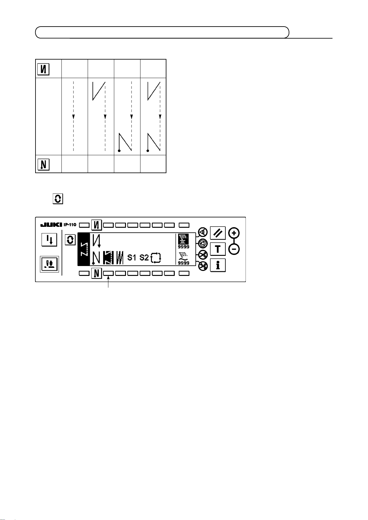
5-5. How to operate the operation panel for sewing stitching patterns
(1) Reverse stitching pattern
2
OFF ON ON
OFF
A
B
Sewing
pattern
C
D
OFF OFF
3
ON ON
Press to display the pattern list screen.
A
B
C
D
1
1) Press switch 1 to select the reverse stitching pattern, and the screen is automatically changed over to
the number of stitches of reverse stitching setting screen to display the number of stitches which has
already been set.
- 9 -
Page 12

2
4
3
5
2) When changing the number of stitches, change it with switches 4 and 5 for setting the number of stitch-
es A through D.
(The range of the number of stitches that can be changed : 0 to 99 stitches)
3) Press switch 2 to set the reverse stitching at the start of sewing.
No setting Reverse stitching
at the start of sewing
Double reverse stitching
at the start of sewing
4) Press switch 3 to set the reverse stitching at the end of sewing.
No setting Reverse stitching
at the end of sewing
Double reverse stitching
at the end of sewing
- 10 -
Page 13
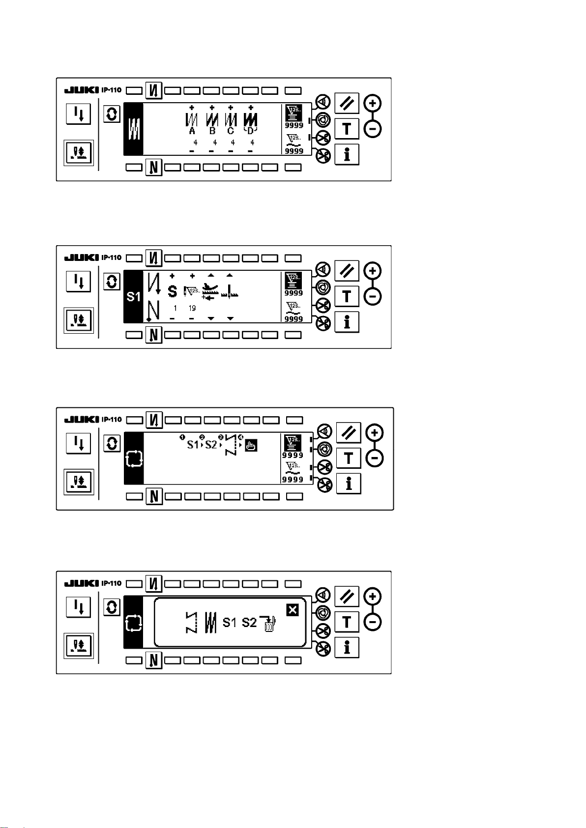
(2) Overlapped stitching pattern
A C C
B B
D
Press to display the pattern list screen.
1
1) Press switch 1 to select the overlapped stitching pattern, and the screen is automatically changed over
to the number of stitches of overlapped stitching setting screen to display the number of stitches which
has already been set.
2
3
2) When changing the number of stitches, change it with switches 2 and 3 for setting the number of stitch-
es for processes A through C. To change the number of times of the whole processes, change it with
switches 4 and 5 for setting the number of processes D.
(The range of the number of stitches A, B and C that can be changed : 0 to 19 stitches. The range of the
number of processes D that can be changed : 0 to 9 times)
3) Depress the front part of the pedal once, and the sewing machine will repeat the normal stitching and
reverse stitching as many as the number of specied times. Then the sewing machine will automatically
make the thread trimmer actuate and will stop to complete the overlapped stitching procedure. (The one-
shot automatic stitching cannot be turned OFF.)
4) When thread trimming prohibiting function 6 is selected, the machine will stop with the needle up upon
completion of the overlapped stitching procedure without performing thread trimming.
4
5
6
- 11 -
Page 14

(3) Programmed stitching pattern
The constant-dimension stitching process can be programmed as many as 20 operation steps. The sewing
conditions including the number of stitches, needle up/down stop mode, automatic thread trimming,
continuous operation steps, lifting/lowering of presser foot and normal/reverse feed stitching can be
separately specified for the respective operation steps. If the lifting of presser foot is specified, the time
during which the presser foot is raised can be also specied.
Example of programmed stitching pattern
4
Step 4
4
4
4
20 20
10
Step 3Step 1
10
Step 2
Press to display the pattern list screen.
Programming procedure is des cribed below
taking the pattern on the left side as an example.
1
1) Press switch 1 to select the programmed stitching pattern, and the screen is automatically changed over
to the programmed stitching setting screen to display the number of stitches and data on the operation
step 1 which have already been specied.
[Step 1]
2 4 6
3 5 7 9
8
!0
!1
- 12 -
Page 15

1) Conrm that step 1 is displayed on the panel. Now, set the number of stitches to 20 using switches 2 and 3.
2) Set the feeding direction to the normal direction using switches 4 and 5.
3) Set the stop state of the sewing machine to the needle-down stop mode using switches 8 and 9.
If the number of stitches is set to 0 stitch or the stop-state of the sewing machine is set to the auto-
matic thread trimming mode , the machine will not proceed to the subsequent operation step.
4) Set the position of the presser foot, when the sewing machine stops, to the upper stop position using
switches 8 and 9.
(If you want to specify, In particular, the length of time during which the presser foot Is raised, set It as
desired using switches !0 and !1. In the Initial state, the length of time Is 60 seconds. Possible setting
range of the time during which the presser foot Is raised : 0.1 sec. to 99.9 sec.)
Settings done by switches 8, 9, !0 and !1 are only available under the setting where the auto-lifter
can be used (i.e., FL ON).
[Step 2]
!2
2
3
5) Press switch !2 once to display step 2.
6) Set the number of stitches to 10 using switches 2 and 3.
[Step 3]
!2
2
3
7) Set the feeding direction to the normal direction, the stop-state of the sewing machine to the needle-
down stop mode and the position of the presser foot to the upper stop position as in the case of step 1.
8) Press switch !2 once to display step 3.
9) Set the number of stitches to 20 using switches 2 and 3.
10) Set the feeding direction to the normal direction, the stop state of the sewing machine to the needle-
down stop mode and the position of the presser foot to the upper stop position as in the case of steps 1
and 2.
- 13 -
Page 16

[Step 4]
!3
!2
2 4 6 8
!4
3 5 7 9
11) Press switch !2 once to display step 4.
12) Set the number of stitches to 10 using switches 2 and
13) Set the feeding direction to the normal direction using switches 4 and
3
.
.
5
14) Set the stop state of the sewing machine to the automatic thread trimming mode using switches 6
.
and
7
15) Set the position of the presser foot, when the sewing machine stops, to the upper stop position using
switches 8 and 9.
16) Select the reverse stitching using switches !3 and !4. This completes the data setting procedure.
17) It is also possible to specify the double reverse stitching using switches !3 and
!4
.
Every time each step is nished, operate the touch-back switch, and the sewing machine runs at a low speed
(stitch compensation operation).
You can p rog ram an oth er sewing processes in th e programmed stitching pattern 2 following the
aforementioned procedure.
In case of pattern 2, the display on the left end of the screen becomes .
When switch is pressed in the programmed stitching setting screen, the screen is changed over to the
number of stitches of reverse stitching screen and the number of stitches of reverse stitching at the time
of programmed stitching can be set. The number of stitches of reverse stitching can be separately set for
patterns 1 and 2.
- 14 -
Page 17

Teaching mode
<
>
In the teaching mode, it is possible to set the number of stitches of the step in a programmed stitching pattern
to the number of stitches that has been actually sewn.
2
1
1) In the programmed stitching setting screen, press teaching switch 1 to select the teaching mode.
2) The indication shown on the number of stitches input section changes to . This shows that the sewing
machine has entered the teaching mode.
3) Depress the front part of the pedal to make the sewing machine perform sewing until the last stitch of the
current operation step is reached.
The number of stitches cannot be inputted by turning the hand wheel by hand or operating the nee-
dle up/down switch.
4) Return the pedal to its neutral position to make the sewing machine stop running. Now, the number of
stitches which has been sewn is displayed.
5) Proceed to the subsequent step using switch 2 or make the sewing machine perform thread trimming.
This completes the input of the number of stitches for operation step 1.
One-shot automatic stitching
<
>
The one-shot automatic stitching function can be separately set by steps.
1
1) In the programmed stitching pattern setting screen, press one-shot automatic stitching switch 1 to select
the one-shot automatic stitching function.
2) A mark is displayed on LCD section of the switch, which shows the one-shot automatic stitching function
has been selected.
3) In the step where the one-shot automatic stitching function has been selected, the sewing machine
will automatically continue sewing, once the sewing machine starts running, until the end of the step is
reached.
- 15 -
Page 18

Continuous stitching mode
<
In this mode, it is possible to make the sewing machine execute the subsequent step after the completion of
the current step.
1) In the programmed stitching pattern setting screen, select the continuous stitching mode using switches
2
.
and
1
2) As long as the continuous stitching mode is selected, you can make the sewing machine execute the
subsequent step set in the program after the completion of the current step by depressing the front part
of the pedal.
>
1
2
To operate the operation panel in combination with the material edge sensor
<
• When the operation panel is used in combination with the material edge sensor, the sewing process can
be completed not by the predetermined number of stitches but by the input signal of the material edge
sensor.
• Carefully read the Instruction Manual for the material edge sensor before using the sensor with the
operation panel.
>
(4) Cycle sewing pattern
Reverse stitching pattern, overlapped stitching pattern, programmed stitching pattern 1 and programmed
stitching pattern 2 can be set and sewn as desired. (As many as eight different patterns can be set.)
1
1) Press switch 1 to display the cycle sewing edit pattern setting pop-up.
- 16 -
Page 19

4 6 8
2
!0 !2
5 7 9
3
!1
Switches 2 and 3 : These switches set the reverse stitching pattern.
Switches 4 and 5 : These switches set the overlapped stitching pattern.
Switches 6 and 7 : These switches set the programmed stitching pattern 1.
Switches 8 and 9 : These switches set the programmed stitching pattern 2.
Switches !0 and !1 : These switches delete the editing step.
Switch !2 : The screen returns to the cycle sewing setting screen.
[Example of setting]
2) Every time the thread trimmer actuates, the machine proceeds to the subsequent pattern which has been
selected. (The step which is being executed is shown in reverse video during execution.)
If the thread trimmer actuates before completion of a pattern, the machine will proceed to the subse-
quent program.
- 17 -
Page 20

6. BOBBIN COUNTER
The number of stitches sewn by the sewing machine is detected. The detected number of stitches is decremented from the
preset counter value (in units of the number of stitches preset using function setting No. 7 "Unit of bobbin thread counting
down." When the counter value changes from the positive value to the negative value (...→ 1
sets of two consecutive blips) and the notication is shown on the popup window to alert the operator to change the bobbin.
-1), the buzzer sounds (3
0
→
→
1
2
Initial value on the bobbin thread counter
for reference
3
1) Press switch 1 to select the bobbin thread counter.
Then press counter reset switch 2 to return the
value indicated on the bobbin thread counter to the
initial value (it has been factory-set to “0” at the time
of delivery).
The bobbin thread counter cannot be reset
during sewing. In this case, make the thread
4
trimmer actuate once.
2) Set an initial value using counter value setting
switches 3 and
4
.
The table below gives the initial se tting valu es for
reference when the bobbin is wound with thread to the
extent that the pinhole in the outside of the bobbin case
is reached as shown in the gure on the left side.
Thread
used
Polyester spun
thread #50
Cotton thread #50
Length of thread
wound round the
bobbin
36 m 1200
31 m 1000
Value on bobbin
thread counter
(stitch length : 3 mm)
(stitch length : 3 mm)
Thread tension rate 100 %
* Actually, the bobbin thread counter is affected by the material thickness and the sewing speed. So, adjust
the initial value of the bobbin thread counter in accordance with the operating conditions.
3) Once the initial value is specied, start the sewing machine.
4) When a minus value is shown on the counter, the buzzer peeps three times and the pop-up display appears, replace the bobbin thread.
Bobbin thread replacement warning pop-up
5) After the bobbin thread has been properly replaced, press counter reset switch 2 to return the value on
the bobbin thread counter to the initial value. Now, re-start the sewing machine.
6) If the remaining amount of bobbin thread is excessive or the bobbin thread runs out before the bobbin
thread counter indicates a minus value, adjust the initial value appropriately using counter value setting
switches 3 and
4
.
If the remaining amount of bobbin thread is excessive ..... Increase the initial value using the “+” switch.
If the remaining amount of bobbin thread is insufcient .... Decrease the initial value using “–” switch.
1. Uneven performance may occur in accordance with the winding way of thread or the thickness of
materials and it is necessary to set the thread trimming amount with some surplus.
2. If the bobbin thread counter is used in combination with the bobbin thread remaining amount de-
tecting device, the bobbin thread counter indicates the number of detections of the bobbin thread
remaining amount detecting device. So, be sure to use the device after carefully reading the Instruction Manual for the bobbin thread remaining amount detecting device.
- 18 -
Page 21

7. NO. OF PCS. COUNTERNO. OF PCS. COUNTER
The No. of pcs. counter counts up the number of nished products every time the machine performs thread
2
...........
→ 9999)
3
The value on the No. of pcs. counter can be modied
using counter value setting switches 3 and 4. The
value on the No. of pcs. cou nter is reset to "0" by
pressing counter reset switch 2.
4
trimming. (0 → 1 → 2
8. RE-SEWING SWITCHRE-SEWING SWITCH
The re-sewing switch is used when the bobbin thread runs out during the programmed stitching pattern
sewing steps or the like.
1) The bobbin thread runs out during the operations
steps for sewing.
1
D
C
Step 4
B
A
Step 3Step 1
d
Step 2
a
e
b c
2) Bring the pedal to its neutral position to make the
sewing machine stop. Now, depress the back part
of the pedal to make the thread trimmer actuate.
3) Turn ON re-sewing switch 1.
4) Replace the bobbin. Slightly feed the material on
the machine in the reverse direction to return the
material to the position where the sewing was interrupted to allow the sewing machine to sew over the
nished seam in step 2. d
5) Depress the front part of the pedal until stop position e of step 2 is reached.
6)
Turn ON re-sewing switch e again at position 1
where the sewing has been interrupted, and the next
step will be indicated on the operation panel. Now,
you can re-start sewing of the programmed stitching
pattern.
*
If the needle thread breaks or any other trouble occurs, which is caused by re-sewing switch 1 during the operation steps (d → e) in the free sewing
mode, bring the pedal to its neutral position, Then
depress the back part of the pedal to actuate the
thread trimmer. Thread the machine head and slightly
feed the material in the reverse direction, and press
re-sewing switch 1. This enables the sewing machine
to continue the sewing under the free sewing mode.
Then operate the operation panel as described in the
aforementioned steps 5) and 6).
a
b
c
To return to the rst step of the programmed
st it ching p attern without using re-sewi ng
switch 1, depress the back part of the pedal
to actuate the thread trimmer. This makes the
operation panel give the step indication 1.
Now, you can start sewing from the rst step
of the programmed stitching pattern.
- 19 -
Page 22

9. NEEDLE UP/DOWN COMPENSATION SWITCHNEEDLE UP/DOWN COMPENSATION SWITCH
Every time needle up/ down co mpen sation swit ch
is pressed, the needle goes up when it is in its lowest
position or comes down when it is in its highest position.
This compensates the stitch by a half of the predetermined
stitch length.
1
Note, however, that the machine does not run continuously
at a low speed even if you keep the switch held pressed.
Also, note that the needle up/down compensation switch is
inoperative after turning the handwheel by hand.
Thread trimmi ng i s opera tive on ly a t the t ime of stitch
compensation after depressing the front part of the pedal once.
10. ON/OFF SWITCHON/OFF SWITCH OF THE MATERIAL EDGE SENSOR
1
• When material edge sensor 1 is pressed, ON/OFF of the material edge
sensor is changed over.
• Wh en the mate rial ed ge s ensor, wh ich is opti onally avai lable, is
connected to the operation panel, the ON/OFF switch of the material
edge sensor becomes effective.
• If th e material ed ge sensor is specified, th e s ewing machine will
automatically stop running or perform thread trimming when the sensor
detects the material edge.
If the material edge sensor is used in combination with the opera-
tion panel, carefully read the Instruction Manual for the material
edge sensor beforehand.
1
11. AUTOMATIC THREAD TRIMMING SWITCHAUTOMATIC THREAD TRIMMING SWITCH
• When automatic thread trimming switch 1 is pressed, ON/OFF of the
automatic thread trimming is changed over.
• This switch is rendered effective, when the material end sensor is turned
ON for the reverse feed stitching pattern, to automatically activate the
thread trimmer upon detection of the material end.
(if the automatic reverse stitching (for end) is specified, the thread
trimmer will actuate after the sewing machine completes the automatic
reverse stitching (for end).)
1
12. ONE-SHOT AUTOMATIC STITCHING SWITCHONE-SHOT AUTOMATIC STITCHING SWITCH
1
• When one-shot automatic stitching switch 1 is pressed, ON/OFF of the
one-shot automatic stitching is changed over.
• This switch is used, in the constant-dimension stitching mode, rectangular
stitching mode, or in the process where the material edge sensor is
specied, to make the sewing machine automatically perform sewing at
the specied speed until the end of the process is reached only by driving
the sewing machine once.
- 20 -
Page 23

13. THREAD TRIMMING PROHIBITION SWITCH
• When thread trimming prohibition switch 1 is pressed, ON/OFF of the
thread trimming prohibition is changed over.
• This switch is used to temporarily make the thread trimming function
inoperative.
The other performance of sewing machine is not affected by this switch.
(If the automatic reverse stitching (for end) is specified, the sewing
machine will perform the automatic reverse stitching at the end of sewing.)
• If the automatic thread trimming switch and the thread trimming
prohibition switch are both specied, the machine will not perform
thread trimming but stop with its needle up.
1
- 21 -
Page 24

14. SIMPLIFIED FUNCTION SETTING
WARNING :
If the solenoid is used under the air drive mode, the solenoid can burn out. Be sure to carefully avoid
the wrong setting of the presser foot lifting device specication.
Function setting items can be simplied in part.
[Simplied function setting screen]
642
3 1
5 7 8
1) Keeping thread trimming prohibiting switch
2) Function items can be changed by pressing
1
held pressed, turn the power ON. Then, the
screen is changed over to the simplied function setting screen. The details displayed on the
screen represent the current settings.
switches 2 and
3, 4
and
5
or
6
and
7
.
* Wiper function (WiP): Switches 2 and
3
This function activates the wiper.
oFF : The wiper does not operate after thread trimming.: The wiper does not operate after thread trimming. The wiper does not operate after thread trimming.
on : The wiper operates after thread trimming (standard setting at the time of delivery): The wiper operates after thread trimming (standard setting at the time of delivery) The wiper operates after thread trimming (standard setting at the time of delivery)
* Auto-lifter (FL): Switches 4 and
5
This function activates the auto-lifter function when the presser foot lifting device (AK) is installed on the
sewing machine.
For the presser foot lifting device specications, solenoid drive mode (+33 V) or air drive mode (+24 V)
can be selected.
The drive source voltage (CN37) is changed over between +33 V and + 24 V according to the drive
mode specication selection.
oFF :: Auto-lifter does not operate. (standard setting at the time of delivery)
(The presser foot does not automatically go up when the program sewing is completed.)
on S :: Auto-lifter operates. (Solenoid drive mode [+33 V])
on A :: Auto-lifter operates. (Air drive mode [+24 V])
* Needle position changeover function for the time when the sewing machine stops (nP): Switches 6 and
7
The needle position at the time when the sewing machine stops can be changed over.
Lo : Lower stop position (standard setting at the time of delivery): Lower stop position (standard setting at the time of delivery) Lower stop position (standard setting at the time of delivery)
UP : Upper stop position: Upper stop position Upper stop position
3) Once you have completed the setting, press switch 8. The screen is changed over to the power switch
OFF notication screen.
[Power switch OFF notication screen]
4) Turn OFF the power switch to exit from the sim-
plied function setting.
If "on" (auto-lifter operates) is selected without the auto-lifter installed, the machine startup is mo-
mentarily delayed at the beginning of sewing. In addition, the one-touch type reverse feed (touch-back)
switch may be disabled. To avoid these troubles, be sure to select "oFF" (auto-lifter does not oper-
ate) when the auto-lifter device is not installed.
- 22 -
Page 25

15. KEY-LOCK FUNCTION SETTING
In order to prevent settings of the number of stitches or detailed settings for processes (A, B, C and D), it
is possible to lock the function setting switches in the current state. (Even under the key-lock mode, the
patterns or bobbin counter can be changed.)
[Key-lock function setting screen]
3
4 5
2
1
1) Keeping thread trimming prohibiting switch 1
and counter value setting switch (+) 2 held
simultaneously, turn the power ON. Then, the
screen is changed over to the key-lock function
setting screen. Setting displayed on the screen
represents the current setting of the key-lock
function.
2) The key-lock function can be changed over
between "on" (key-lock function is effective) and
"oFF" (key-lock function is ineffective [standard
setting at the time of delivery]) by pressing
switches 3 and 4.
3) Once you have completed the setting, press
switch 8. The screen is changed over to the
power switch OFF notication screen.
[Power switch OFF notication screen]
4) Turn OFF the power switch to exit from the sim-
plied function setting.
[Number of reverse feed stitches setting screen] (Example of display)
6
5) When the key-lock function is "on" (key-lock
function is effective), key icon 6 is displayed on
the screen.
- 23 -
Page 26

16. FUNCTION SETTING
Functions of the sewing machine can be programmed and the number of stitches and the number of
revolutions can be changed.
Refer to the Instruction Manual for the SC-920 for how to change the function setting items and for the details
of the functions.
[Function settings list screen]
1) Keeping switch 1 held pressed, turn the power
ON. Then the screen is changed over to the
function settings list screen.
When you press switch 2, the screen is
changed over to the function setting display
screen.
12
[Function setting display screen]
3
Function
setting No.
Set value
2) Function setting item number can be incremented
or decremented by pressing switches 3 and
4
.
3) Once you have determined the target function
setting number, press switch 5. The screen
is changed over to the function setting popup
screen.
4 5
[Function setting popup screen]
6
4) Function setting item number can be incremented
or decremented by pressing switches 6 and 7.
5) Once you have completed set value changing,
press switch 8. The screen is changed over
to the function setting display screen and the
changed set value is displayed on the screen.
6) Turn OFF the power switch to exit from the func-
7 8
tion setting.
* To change two or more different function setting
numbers, repeat the aforementioned steps of
procedure 2) through 5) as required.
Example) [To change the number of stitches 0 to 3 using the soft-start function (function setting No. 1)]
[Function setting display screen]
3
1) Press switches 3 and 4 to select function setting No. 1.
4 5
2) Press switch 5. The screen is changed over to
the function setting popup screen.
- 24 -
Page 27

[Function setting popup screen]
6
7
[Function setting display screen]
3) Press switches 6 and 7 to change the set
value to 3.
4) Press switch 8. The screen is changed over to
the function setting display screen.
8
5) The changed set value is displayed on the func-
tion setting display screen.
6) Turn OFF the power switch to exit from the func-
tion setting.
Refer to the Instruction Manual for the function setting list and the details of the function setting
items.
Function setting list
No
1 Soft start
2 Material end
3
4 Number of
5
6 Bobbin thread
7 Unit of bobbin
*
Item Description
function
sensor function
Thread trimming
function by
material end
sensor
stitches for
material end
sensor
Flicker reducing
function
counting
function
thread counting
down
The number of stitches to be sewn at a low speed when the softstart function is used at the start of sewing.
0 : The function is not selected.
1 to 9 : The number of stitches to be sewn under the soft-
start mode.
This item is not used on the IP-110F.
This item is not used on the IP-110F.
This item is not used on the IP-110F.
Flicker reducing function
0 : Flicker reducing function is not operative.
1 : Flicker reducing function is effective
Bobbin thread counting function
0 : Bobbin thread counting function is not operative.
1 : Bobbin thread counting function is operative.
Unit of bobbin thread counting down
0 : 1 Count/10 stitches
1 : 1 Count/15 stitches
2 : 1 Count/20 stitches
3 : 1 Count/thread trimming
Setting range
0 to 9
(Stitches)
0/1
0/1
0 to 19
(Stitches)
0/1
0/1
0 to 3
Indication of function setting
1 0
2 0
3 0
4 5
5 0
6 1
7 0
Do not change the set values with asterisk (*) mark as they are functions for maintenance. If the standard set value set at the
*
time of delivery is changed, it is in danger of causing the machine to be broken or the performance to be deteriorated.
If it is necessary to change the set value, please purchase the Engineer’s Manual and follow the instructions.
- 25 -
Page 28

No
8 Number of
*
9 Thread
10 Setting of
11 Operation
13 Function of
*
14 Sewing counter Counting function of sewing (number of completion of process)
15 Thread wiping
21 Function of
22 Needle up/down
25 Thread trimming
29 Initial motion
30 Function of
31
32 Effective
33 Thread trimming
35 Number of
*
36 Number of
*
37 Number of
Item Description
rotation of
reverse feed
stitching
trimming
prohibiting
function
needle bar stop
position when
the sewing
machine stops.
conrmation
sound for
operation panel
prohibiting start
of the sewing
machine by
bobbin thread
counter
function after
thread trimming
neutral presser
lifting
correction
switch
changeover
function
operation after
turning the
handwheel by
han
time of backtack
reverse feed
stitching on the
way
Number of
stitches of reverse
feed stitching on
the way
condition of
reverse feed
stitching on the
way when the
sewing machine
is stopping.
function by
reverse feed
stitching on the
way
rotation at a low
speed
rotation of
thread trimming
rotation of softstart
Sewing speed of reverse feed stitching
This item is not used on the IP-110F.
Position of needle bar is specified when the sewing machine
stops.
0 : Predetermined lowest position
1 : Predetermined highest position
Operation conrmation sound for operation panel
0 : Operation conrmation sound is not generated
1 : Operation conrmation sound is generated.
Function of prohibiting start of the sewing machine by bobbin thread counting
0 : When counting is out (-1 or less) Function of prohibiting
start of the sewing machine is not operative.
1 : When counting is out (-1 or less) Function of prohibiting
start of the sewing machine after thread trimming is operative.
2 : When counting is out (-1 or less), the sewing machine
stops once. Function of prohibiting start of the sewing
machine after thread trimming is operative.
0 : Sewing counter function is not operative.
1 : Sewing counter function is operative. (Every time thread
trimming is performed)
2 : With the sewing counting switch input function
Thread wiping operation after thread trimming is specied.
0 : Thread wiping is not carried out after thread trimming
1 : Thread wiping is carried out after thread trimming
Function of lifting presser foot whe n the pedal is in neutr al
position.
0 : Function of neutral automatic presser lifting is not opera-
tive.
1 : Selection of function of neutral presser lifting.
Function of the needle up/down correction switch is changed
over.
0 : Needle up/down compensation
1 : One stitch compensation
Thread trimming operation after moving the needle away from
its upper or lower position by turning the handwheel by hand is
specied.
0 : Thread trimming operation is carried out after turning the
handwheel by hand
1 : Thread trimming operation is not carried out after turning
the handwheel by hand
This function sets the suction time of initial motion of back-tack
solenoid.
50 ms to 500 ms
Function of reverse feed stitching on the way
0 : Function of reverse stitching on the way is not operative.
1 : Function of reverse feed stitching on the way is operative.
Number of stitches of reverse feed stitching on the way.
Effective condition of reverse feed stitching on the way
0 : Function is not operative when the sewing machine stops.
1 : Function is operative when the sewing machine stops.
Thread trimming function by reverse feed stitching on the way
0 : Automatic thread trimming function after completion of
reverse feed stitching on the way is not operative.
1 : Automatic thread trimming after completion of reverse
feed stitching on the way is performed.
Lowest speed by pedal
(The MAX value differs by machine head.)
Thread trimming speed
(The MAX value differs by machine head.)
Sewing speed at the start of sewing (soft-start)
(The MAX value differs by machine head.)
Setting range
150 to 3,000
(sti/min)
0/1
0/1
0/1
0 to 2
0 to 2
0/1
0/1
0/1
0/1
50 to 500
(ms)
0/1
0 to 19
(Stitches)
0/1
0/1
150 to MAX
(sti/min)
100 to MAX
(sti/min)
100 to MAX
(sti/min)
Indication of function setting
8 1900
9 0
10 0
11 1
13 0
14 1
15 1
21 0
22 0
25 1
29 70
30 0
31 4
32 0
33 0
35 200
36 420
37 800
Do not change the set values with asterisk (*) mark as they are functions for maintenance. If the standard set value set at the
*
time of delivery is changed, it is in danger of causing the machine to be broken or the performance to be deteriorated.
If it is necessary to change the set value, please purchase the Engineer’s Manual and follow the instructions.
- 26 -
Page 29

No
38 One-shot speed One-shot speed (The max. value depends on the number of
39 Pedal stroke
*
40 Low speed
*
41 Starting position
*
42 Starting position
*
43
*
44
*
45
*
47
48
*
49
50
Item Description
rotation of the sewing machine head.)
at the start of
rotation
section of pedal
of lifting presser
foot by pedal
of lowering
presser foot
Pedal stroke 2 for
starting thread
trimming
Pedal stroke
for reaching the
maximum number
of rotation
Compensation of
neutral point of
the pedal
Auto-lifter
selecting function
Pedal stroke 1 for
starting thread
trimming
Lowering time of
presser foot
Selection of
the pedal
specication
Position where the sewing machine starts rotating from pedal
neutral position (Pedal stroke)
Position where the sewing machine starts accelerating from
pedal neutral position (Pedal stroke)
Position where the cloth presser starts lifting from pedal neutral
position (Pedal stroke)
Starting position of lowering presser foot
Stroke from the neutral position
Position 2 where the thread trimming starts from pedal neutral
position (When the function of lifting presser foot by pedal is
provided.) (Pedal stroke)
Position where the sewing machine reaches its highest sewing
speed from pedal neutral position (Pedal stroke) 10 to 150
Compensation value of the pedal sensor
Limitation time of waiting for lifting solenoid type auto-li fter
device
Position where thread trimming starts from pedal neutral position
(Standard pedal) (Pedal stroke)
Lo w er i ng ti me of pre sse r foo t afte r t he ped al has been
depressed.
(Start of rotation of the sewing machine is delayed during this
time.)
Change the setting according to the pedal specication.
0 : KFL
1 : PFL
Setting range
150 to MAX
(sti/min)
10 to 50
(0.1 mm)
10 to 100
(0.1 mm)
– 60 to –10
(0.1mm)
8 to 50
(0.1 mm)
– 60 to –10
(0.1 mm)
(0.1 mm)
–15 to 15
10 to 600
(second)
– 60
to – 10
(0.1 mm)
0
to 250
(10 ms)
0/1
Indication of function setting
38 2500
39 30
40 60
41 -21
42 10
43 -51
44 150
45 0
47 60
48 -35
49 140
50 1
51 Compensation of
solenoid-on timing
of reverse feed
stitching at the
start of sewing
52 Compensation of
solenoid-off timing
of reverse feed
stitching at the
start of sewing
53 Compensation
of solenoid-off
timing of reverse
feed stitching at
the end of sewing
Foot lift after
55
thread trimming
Reverse
56
revolution to lift
the needle after
thread trimming
Function
58
of holding
predetermined
upper/lower
position of the
needle bar
Function of Auto/
59
Manual changeover of reverse
feed stitching at
the start of sewing
Function of stop
60
immediately after
reverse feed
stitching at the
start of sewing
Compensation of starting the solenoid for reverse feed stitching
when reverse feed stitching at the start of sewing is performed.
Co mp en sa ti on of relea si ng the sol en oi d fo r reverse fee d
stitching when reverse feed stitching at the start of sewing is
performed.
Co mp en sa ti on of relea si ng the sol en oi d fo r reverse fee d
stitching when reverse feed stitching at the end of sewing is
performed.
Function of lifting presser foot at the time of (after) thread trimming
0 : Not provided with the function of lifting presser foot after
thread trimming
1 :
Provided with the function of lifting presser foot
after thread trimming
Function of reverse revolution to lift the needle at the time of
(after) thread trimming
0 : Not provided with the function of reverse revolution to lift
the needle after thread trimming
1 : Provided with the function of reverse revolution to lift the
needle after thread trimming
Function of holding predetermined upper/lower position of the needle bar
0 : Not provided with the function of holding predetermined
upper/lower position of the needle bar
1 : Provided with the function of holding predetermined upper/
lower position of the needle bar (holding force is weak.)
2 : Provided with the function of holding predetermined upper/
lower position of the needle bar (holding force is medium.)
3 : Provided with the function of holding predetermined upper/
lower position of the needle bar (holding force is strong.)
This function can specify the sewing speed of reve rse feed
stitching at the start of sewing.
0 : The speed will depend on the manual operation by pedal, etc.
1 :
The speed will depend on the specied reverse feed stitching speed (No. 8).
Function at the time of completion of reverse feed stitching at
the start of sewing
0 : Not provided with the function of temporary stop of the
sewing machine at the time of completion of reverse feed
stitching at the start of sewing
1 : Provided with the function of temporary stop of the sew-
ing machine at the time of completion of reverse feed
stitching at the start of sewing.
automatically
– 36 to 36
(10°)
– 36 to 36
(10°)
– 36 to 36
(10°)
0/1
0/1
0 to 3
0/1
0/1
51 -8
52 10
53 15
55 1
56 0
58 0
59 1
60 0
Do not change the set values with asterisk (*) mark as they are functions for maintenance. If the standard set value set at the
*
time of delivery is changed, it is in danger of causing the machine to be broken or the performance to be deteriorated.
If it is necessary to change the set value, please purchase the Engineer’s Manual and follow the instructions.
- 27 -
Page 30

No
Change-
64
over speed of
condensation
stitch or EBT (end
back tack)
Function of soft-
70
down of presser
foot
Double reverse
71
feed stitching
function
Item Description
Initial speed when starting condensation stitch or EBT
Presser foot is slowly lowered.
0 : Presser foot is rapidly lowered.
1 : Presser foot is slowly lowered.
This item is not used on the IP-110F.
Setting range
0 to 250
(sti/min)
0/1
0/1
Indication of function setting
64 180
70 0
71 1
Sewing
72
machine startup
selecting
function
Retry function
73
One-shot function
76
84
Initial motion
*
Do not change the set values with asterisk (*) mark as they are functions for maintenance. If the standard set value set at the
*
suction time of
presser foot lifting
solenoid
87
Function of pedal
curve selection
90
Initial motion up
stop function
Function of prohibiting
91
compensation
operation after turning
handwheel by hand
Function of
92
reducing speed
of reverse feed
stitching at the
start of sewing
Function added to
93
needle up/down
compensating
switch
Continuous +
94
One-shot nonstop
function
Max. number of
96
rotation setting
Needle cooler
103
output OFF
delay time
Main shaft
120
reference angle
compensation
Up position
121
starting angle
compensation
DOWN position
122
starting angle
compensation
Setting of
124
energy-saving
function during
standby
Current limit at the startup of sewing machine is specied.
0 : Normal (Current limit is applied during startup)
1 : Rapid (Current limit is not applied during startup)
This function is used when needle cannot pierce materials .
0 : Normal
1 : Retry function is provided.
This item is not used on the IP-110F.
Suction motion time of presser foot lifting solenoid
Pedal curve is selected. (Improving pedal inching operation)
Number of rotations
Automatic UP stop function is set immediately after turning ON the
power.
0 : off
1 : on
It is effective in combination with the machine head provided
with tension release function.
0 : Tension release function is ineffective.
1 : Tension release function is effective.
Function to reduce speed at the time of completion of reverse
feed stitching at the start of sewing.
0 : Speed is not reduced.
1 : Speed is reduced.
Operation of needle up/down compensating switch is changed
after turning ON the power or thread trimming.
0 : Normal (needle up/down compensating stitching only)
1 : One stitch compensating stitching is performed only when
aforementioned changeover is made. (Upper stop / upper
stop)
Th e func ti on tha t d oe s not st o p the se wi ng mac hi n e by
combining continuous stitching with one-shot stitching using the
program sewing function which is available in the IP operation
panel.
0 : Normal (The sewing machine stops when a step is com-
pleted.)
1 : The sewing machine does not stop when a step is com-
pleted and proceeds to next step.
Max. number of rotation of the sewing machine head can be set.
(The MAX value differs by machine head.)
Delay time from the stop of sewing machine to the output OFF is
specied using the needle cooler output function.
Main shaft reference angle is compensated.
Angle to detect UP position starting is compensated.
Angle to detect DOWN position starting is compensated.
Set ting to re duc e the power consumption while the sewing
machine is in standby state
0 : Energy-saving mode is ineffective
1 : Energy-saving mode is effective
2
0
1
Pedal stroke
0/1
0/1
0/1
50 to 500
(ms)
0/1/2
0/1
0/1
0/1
0/1
0/1
150 to MAX
(sti/min)
100 to
2000 ms
–50 to 50
–15 to 15
–15 to 15
0/1
72 0
73 1
76 0
84 140
87 0
90 1
91 1
92 0
93 0
94 0
96 4000
103 500
120 -23
121 5
122 0
124 0
time of delivery is changed, it is in danger of causing the machine to be broken or the performance to be deteriorated.
If it is necessary to change the set value, please purchase the Engineer’s Manual and follow the instructions.
- 28 -
Page 31

17. OPTIONAL INPUT/OUTPUT SETTINGS
The optional input/output function is used for outputting signals which are allocated to the connectors and
for controlling a certain simple operation of the sewing machine by allocating various functions to the input/
output connectors of the SC-920 (control box).
Refer to the Instruction Manual for the SC-920 for details.
[Function settings list screen]
1) Keeping switch 1 held pressed, turn the power
ON. Then the screen is changed over to the
function settings list screen.
When you press switch 2, the screen is
changed over to the sewing common data
12
[Sewing common data screen]
screen.
2) When you press switch 3, the screen is
changed over to the option input/output setting
screen.
3
[Option input/output setting screen]
• To allocate a function to the input connectorTo allocate a function to the input connector
4 6 8
!0 !2 !4
3) Press switches 4 and 5 to select the optional
input number corresponding to the input connector pin number.
noP noP
901 0 951 0
4)
Press switches 6 and 7 to select the function
code number and abbreviation of the input function.
5) Press switches 8 and 9 to select the input
status (L: Active when Low is input, or H: Active
5 7 9
!1 !3 !5 !6
when High is input) of the selected input function. If function code No. 0 is selected, the input
status selection is not required.
• To allocate a function to the output connector
6) Press switches !0 and !1 to select the optional output number corresponding to the output connector pin
number.
7) Press switches !2 and !3 to select the function code number and abbreviation of the output function.
8) Press switches !4 and !5 to select the output status (L: Low is output when Low is active, or H: High is
output when High is active) of the selected input function. If function code No. 0 is selected, the output
status selection is not required.
9) Once you have completed the setting, press switch !6. The screen is changed over to the sewing com-
mon data screen.
10) Turn OFF the power switch to exit from the function setting.
Refer to the Instruction Manual for the SC-920 for the input/output connector numbers and pin num-
bers and the relation between these numbers and the displayed number.
- 29 -
Page 32

(Example) [To allocate the thread trimming function to the input connector (CN48,1)
[Option input/output setting screen]
4 6
noP noP
901 0 951 0
5 7
8
TSW noP
L
901 4 951 0
9
[Sewing common data screen]
!6
1) Press switches 4 and 5 to select input display
No. 901 which represents the input connector
(CN48, 1.)
2) Press switches 6 and 7 to select the function
code No. 4 and abbreviation "TSW" of the input
function.
3) Press switches 8 and 9 to select the input
status of the input function. Set the input status
code "L" if the thread trimmer activates when the
input signal is Low, or "H" if the thread trimmer
activates when the signal is High.
4) Press switch !6. The screen is changed over to
the sewing common data screen.
5) Turn OFF the power switch to exit from the function setting.
Refer to the Instruction Manual for the SC-920 for the input/output connector numbers and pin num-
bers and the relation between these numbers and the displayed number.
18. AUTOMATIC COMPENSATION OF NEUTRAL POINT OF THE PEDAL SENSOR
Whenever you have replaced the parts such as the pedal sensor and spring, be sure to carry out the
following procedure.
[Pedal-sensor neutral-point automatic compensation screen]
1
1) Keep one-shot automatic sewing switch
pressed, turn the power ON. Then, the screen is
changed over to the pedal-sensor neutral-point
automatic compensation screen.
2) When the neutral point of the pedal sensor is
properly corrected, the message "OK" and the
compensation value (the compensation value
"0" shown in the gure on the left is a value for
reference) are displayed and the buzzer sounds
(one short blip).
3) Turn OFF the power switch to exit from the func-
tion setting.
1
held
1. The pedal is depressed when the power is turned ON, the correct compensating operation cannot
be carried out. Never place your foot or anything on the pedal. The audible warning sounds (two sin-
gle tones, i.e., two blips) and neither the message "OK" nor the compensation value are displayed.
2. If any message or value other than "OK" or the compensation value, refer to the Engineer's Manual.
- 30 -
Page 33

19. INITIALIZATION OF THE SETTING DATA
Data on the function setting items can be returned to the standard set values.
[Function setting data initialization screen]
1) Keeping reset switch 1 and counter value
1 2
3
switch (+) 2 held simultaneously pressed, turn
the power ON. Then the screen is changed over
to the function setting data initialization screen.
2) When you press switch 3, the process for
totally returning the function setting data to the
standard set values (initialization operation) is
executed.
3) Once the process is completed (approximately
one second later), the buzzer sounds (three
single tones, i.e., blip, blip, blip) and screen is
changed over to the power switch OFF notication screen.
Do not run the power OFF during the ini-
tialization operation. It can damage the
program of the main body.)
[Power switch OFF notication screen]
4) Turn OFF the power switch to exit from the ini-
tialization.
1. The neutral point compensation value of the pedal sensor is also initialized by carrying out the
initialization operation. It is therefore necessary to carry out the automatic compensation of the
neutral point of the pedal sensor without exceptions before using the sewing machine.
(Refer to "18. Automatic compensation of neutral point of the pedal sensor" p. 30.)
2. The machine head angle adjustment value is also initialized by carrying out the initialization oper-
ation It is therefore necessary to carry out the machine head angle adjustment without exceptions
before using the sewing machine.
(Refer to "4. Sewing machine angle adjustment" p.3.)
3. Sewing data programmed on the operation panel are not initialized by carrying out the initializa-
tion operation.
- 31 -
Page 34

20. INFORMATION
Various data can be set or checked on the information screen.
Operator level
1) Turn ON the power.
2) Press switch 1 to display the information screen.
Information screen
■
1
: Sewing management
1
information
: Date and time setting
2
1
Sewing management information
●
The sewing management information consists of the maintenance management function and working
measurement function.
2
(1) Maintenance management function
Sewing management function screen
■
1
1) Press switch 1 to change over the screen to the maintenance management function screen.
- 32 -
Page 35

Maintenance function screen
■
The time for needle changing, the time for cleaning and the time for oil changing can be set to continuously
display numeric values or display the notication after the lapse of preset time.
Refer to the Engineer's Manual for details.
2
3
4
[Explanation of the respective items]
Time of replacement of needle ..... Unit : X 1,000 stitches
2
Time of cleaning ............................ Unit : Hour
3
Time of replacement of oil ............. Unit : Hour
4
[Explanation of the contents of display]
(Numerator / denominator)
* Number of remaining stitches up to *thousand stitches /
**
Example) Replacement of needle
100 / 1600 k
thousand stitches
Time of replacement of needle is informed every 1,600 thousand stitches.
Time of replacement of needle is informed after 100 thousand stitches.
When 2, 3 and 4 switches are pressed, the clear checking screen is displayed.
Clear screen
■
1
2
: The screen returns to the maintenance function screen without performing clearing.
1
: The screen returns to the maintenance function screen after executing clearing.
2
- 33 -
Page 36

Warning screen
■
Warning screen is displayed when the warning time is reached.
1
2
: When 1 is pressed, the screen can be cleared. However, the counter itself cannot be cleared. In case
1
of the replacement of needle, the warning screen is displayed at intervals of 10 minutes until clearing
is performed. In case of other warnings, the warning screen is displayed at the time of turning ON the
power until the counter is cleared.
: When 2 is pressed, the screen is cleared and the counter value is cleared as well. From this time,
2
counting starts newly.
[Setting of the warning setting time]
Infomation screen
■
1
1) Press switch 1 for approximately three seconds in the information screen.
Sewing management function screen
■
2
2) Press 2 to display the maintenance function screen.
(For other functions, refer to the Engineer’s Manual.)
- 34 -
Page 37

Maintenance function screen
■
3
5
: Input screen of time of replacement of needle (number of stitches : unit : X 1,000 stitches) is displayed.
3
: Input screen of time of cleaning (time : unit : h) is displayed.
4
: Input screen of time of replacement of oil (time : unit : h) is displayed.
5
Various input screen (Time for needle changing, time for cleaning and the time for oil changing)
■
4
7 8
Press 7 to display the clear checking screen. After inputting the set value, press 8 to determine.
In case of stopping the warning function, set the set value to “0”.
It is possible to individually set replacement of needle, cleaning, and replacement of oil respectively.
In case of stopping all, set “0” to each.
- 35 -
Page 38

(2) Working measurement function
Sewing management function screen
■
1
1) Press switch 1 to change over the screen to the working measurement function screen.
Working measurement function screen
■
Working factor, working mean speed, pitch time and machine time can be measured on this screen.
2
3
[Explanation of the respective items]
Working factor .................................. Unit : %
Working mean speed .......................Unit : sti/min
Pitch time .........................................Unit : Second
Machine time ...................................Unit : Second
2) Press 3 to start the working measurement.
3) To stop the measurement, press 3 again.
4) The result of measurement can be cleared with 2.
When “Clear” is not executed, the measurement from the last time can be continued.
- 36 -
Page 39

Date and time setting
●
The current date and time can be set to display on the screen.
Information screen
■
1
1) Press switch 1 to change over the screen to the date and time setting screen.
Date and time setting screen
■
2345678
!0!1!2
9
2) Press switches 2 and 3, 4 and 5, and 6 and 7 to increment/decrement the date.
3) Press switches 8 and 9, !0 and !1, and !2 and !3 to increment/decrement the time.
4) Once you have set the date and time, press switch !4. The screen is changed over to the information
screen.
Information screen
■
5) The set date and time are displayed on the information screen and the clock starts to operate. (When
you have set the date and time to "2009-10-01 10:00:00" and press switch !4, the screen display will be
as shown in the above gure.)
!3 !4
- 37 -
Page 40

21. EXTERNAL INTERFACE
External interface means the section to connect the operation panel and the system which is different from
the operation panel.
For the use and details, refer to the Engineer's Manual.
1) Media slot
Media slot is installed in the face cover located on the left side of operation panel.
2) RS-232C port
RS-232C connector is installed in the rubber cap located on the back side of operation panel.
3) General input port (Production support switch connecting connector)
General input connector, CN105 is installed in the cord outlet cover located on the back side of operation
panel.
22. ERROR DISPLAY
There are two different kinds of errors, those output from the operation panel and those from the
SC-920 (control box). Both kinds of errors are notied by the error screen and the buzzer.
Three different kinds of screens of the panel display screen appear due to the difference of the procedures.
1) Error screen disappears when the operator removes the cause.
Example) Cover of the slot of media is open. Close the cover.
2) Press the reset switch, and remove the cause of error after erasing the error screen.
3) Remove the cause of error after turning OFF the power.
- 38 -
Page 41

22-1. Error code list (Error display in panel)
There are the following error codes in this device. These error codes interlock (or limit function) and inform
the problem so that the problem is not enlarged when any problem is discovered. When you request our
service, please conrm the error codes.
No. Description of error detected Cause of occurrence expected Items to be checked
− Media cover open • Cover of the slot of media is open. • Close the cover.
E000 Execution of data initialization
(This is not the error.)
E003 Disconnection of
synchronizer connector
E004 Synchronizer lower position
sensor failure
E005 Synchronizer upper position
sensor failure
E007 Overload of motor • When the machine head is locked.
E011 Media is not inserted. • Media is not inserted. • Turn the power OFF and check the media.
E012 Read error • Data of media cannot be read. • Turn the power OFF and check the media.
E013 Write error • Data of media cannot be written. • Turn the power OFF and check the media.
E014 Write protect • Media is in the state of writing prohibition. • Turn the power OFF and check the media.
E015 Format error • Formatting cannot be performed. • Turn the power OFF and check the media.
E016 External media capacity over • Capacity of media is short. • Turn the power OFF and check the media.
E019 File size over • File is too large. • Turn the power OFF and check the media.
E032 File interchangeability error • There is no interchangeability of le. • Turn the power OFF and check the media.
E070 Slip of belt • When the machine head is locked.
E071 Disconnection of motor
output connector
E072 Overload of motor at the time
of thread trimming motion
E220 Grease-up warning • When the predetermined number of stitches
E221 Grease-up error • When the predetermined number of stitches
E302 Fall detection switch failure
(When the safety switch
works)
• When the machine head is changed.
• When the initialization operation is executed
• When position detection signal is not input
from the sewing machine head synchronizer.
• When the synchronizer has broken.
• Belt is loose.
• Machine head is not proper.
• Motor pulley is not proper.
• When sewing extra-heavy material beyond
the guarantee of the machine head.
• When the motor does not run.
• Motor or driver is broken.
• Belt is loose.
• Disconnection of motor connector • Check the motor output connector for loose
• Same as E007 • Same as E007
has been reached.
has been reached and the sewing is not
possible.
• When fall detection switch is input in the
state that the power is turned ON.
• Check the synchronizer connector (CN33)
for loose connection and disconnection.
• Check whether the synchronizer cord has
broken since the cord is caught in the
machine head.
• Check the belt tension.
• Check the setting of the machine head.
• Check the setting of the motor pulley.
• Check whether the thread has been
entangled in the motor pulley.
• Check the motor output connector (4P) for
loose connection and disconnection.
• Check whether there is any holdup when
turning the motor by hand.
• Check whether there is any holdup when
turning the motor by hand.
• Check the belt tension.
connection and disconnection.
• Replenish the specied places with grease
and reset.
(For the details, refer to the data of the
machine head.)
• Replenish the specied places with grease
and reset.
(For the details, refer to the data of the
machine head.)
• Check whether the machine head is tilted
without turning OFF the power switch (sewing
machine operation is prohibited for safety
sake).
• Check whether the fall detection switch cord
is caught in the sewing machine or the like.
• Check whether the fall detection switch lever
is caught in something.
• Check whether the contact of the tilt
detection switch lever with the machine table
is inadequate. (The table has a dent or the
mounting location of the bed strut is too far)
- 39 -
Page 42

No. Description of error detected Cause of occurrence expected Items to be checked
E303 Semicircular plate sensor
error
E730 Encoder failure • When the motor signal is not properly
E731 Motor hole sensor failure
E733 Inverse rotation of motor • This error occurs when the motor is running
E808 Solenoid short circuit • Solenoid power does not become normal
E809 Holding motion failure • Solenoid is not changed over to holding
E810 Solenoid current abnormality • Solenoid rare short-circuit. • Solenoid resistance
E811 Abnormal voltage • When voltage higher than guaranteed one is
E906 Operation panel transmission
failure
E924 Motor driver failure • Motor driver has broken.
E942 Faulty EEPROM • Data cannot be written on the EEPROM. • Turn the power OFF.
• Semicircular plate sensor signal cannot be
detected.
inputted.
at 500 sti/min or more in the opposite
direction of that of rotation indication during
motor is running.
voltage.
motion.
inputted.
• 200V has been inputted to SC-920 of 100V
specications.
• JUS : 220V is applied to 120V box.
• CE : 400V is applied to 230V box.
• When voltage lower than guaranteed one is
inputted.
• 100V has been inputted to SC-920 of 200V
specications.
• JUS : 120V is applied to 220V box
• Inner circuit is broken by the applied
overvoltage
• Disconnection of operation panel cord
• Operation panel has broken.
• Check whether the machine head
corresponds with the machine type setting.
• Check whether the motor encoder connector
is disconnected.
• Check the motor signal connector (CN39) for
loose connection and disconnection.
• Check whether the motor signal cord has
broken since the cord is caught in the
machine head.
• Check whether the inserting direction of the
motor encoder connector is wrong.
• Connection of the encoder of main shaft
motor is wrong.
• Connection for the electric power of main
shaft motor is wrong.
• Check whether the machine head cord is
caught in the pulley cover or the like.
• Check whether the solenoid is abnormally
heated. (CTL circuit board asm. Circuit is
broken.
• Check whether the applied power voltage is
higher than the rated voltage + (plus) 10% or
more.
• Check whether 100V/200V changeover
connector is improperly set.
In the aforementioned cases, POWER p.c.b
is broken.
• Check whether the voltage is lower than the
rated voltage - (minus) 10% or less.
• Check whether 100V/200V changeover
connector is improperly set.
• Check whether fuse or regenerative
resistance is broken.
• Check the operation panel connector
(CN34, CN35) for loose connection and
disconnection.
• Check whether the operation panel cord
has broken since the cord is caught in the
machine head.
- 40 -
 Loading...